Facility Operations Maturity Model
87
SCHNEIDER ELECTRIC IT MISSION CRITICAL SERVICES & SOFTWARE, INC. Facility Operations Maturity Model 10/17/2013
Transcript of Facility Operations Maturity Model

SCHNEIDER ELECTRIC IT MISSION CRITICAL SERVICES & SOFTWARE, INC.
Facility Operations Maturity Model
10/17/2013

Contents
Introduction .................................................................................................................................................. 4 Scope ............................................................................................................................................................. 4 Overview ....................................................................................................................................................... 4 Facility Operations Maturity Model Definitions for Levels of Maturity ........................................................ 5 I. Environmental Health and Safety ........................................................................................................... 7 1. Illness and Injury Prevention ................................................................................................................. 7 1.1. Workplace safety program............................................................................................................. 7 1.2. Personal Protective Equipment (PPE) ............................................................................................ 8 1.3. Electrical Safety .............................................................................................................................. 9 1.4. Hazard Analysis ............................................................................................................................ 10 1.5. Hazard Communications .............................................................................................................. 11 1.6. Hazardous Materials .................................................................................................................... 11
2. Statutory Compliance ......................................................................................................................... 12 2.1. Environmental (US examples) ...................................................................................................... 12 2.2. Safety (US examples) ................................................................................................................... 16
II. Emergency Preparedness and Response ............................................................................................. 18 3. Emergency Response Procedures ....................................................................................................... 18 3.1. Emergency Operating Procedures ............................................................................................... 18 3.2. Crisis Management Plan .............................................................................................................. 19 3.3. Business Continuity/Disaster Recovery Procedures .................................................................... 20
4. Scenario Drills ...................................................................................................................................... 21 4.1. Drill Process, Procedure, Scheduling and Execution .................................................................... 21
5. Incident Management ......................................................................................................................... 22 5.1. Notification .................................................................................................................................. 22 5.2. Incident Identification and Reporting .......................................................................................... 23 5.3. “Lessons Learned”/Near miss reporting ...................................................................................... 24
III. Maintenance Management ................................................................................................................ 26 6. Asset Management ............................................................................................................................. 26 6.1. Asset Database ............................................................................................................................. 26 6.2. Scopes of Service .......................................................................................................................... 27
7. Work Order Management ................................................................................................................... 28 7.1. Scheduling & Tracking .................................................................................................................. 28 7.2. Recording and Analysis ................................................................................................................ 30 7.3 Corrective or Follow‐on Activities ................................................................................................. 30 7.4. Reporting ...................................................................................................................................... 31
8. Computerized Maintenance Management System ............................................................................ 32 8.1. Administration ............................................................................................................................. 32 8.2. Utilization ..................................................................................................................................... 32 8.3. Functionality ................................................................................................................................ 33
9. Vendor Management .......................................................................................................................... 34

9.1. Selection ....................................................................................................................................... 34 9.2. Performance metrics .................................................................................................................... 36 9.3. Vendor Service Reports ................................................................................................................ 37
10. Spare Parts Management ................................................................................................................. 37 10.1. Identification .............................................................................................................................. 37 10.2. Inventory and Storage ................................................................................................................ 38
IV. Site Management ............................................................................................................................... 40 11. Infrastructure Management ............................................................................................................. 40 11.1. Facility Monitoring ..................................................................................................................... 40 11.2. Capacity Management and Reporting ....................................................................................... 41 11.3. Data Center Infrastructure Management (DCIM) – Integrated IT and Facility Systems Management ....................................................................................................................................... 42
12. Site Operations.................................................................................................................................. 43 12.1. Administrative Processes and Procedures ................................................................................. 43 12.2. Technical Documentation .......................................................................................................... 44 12.3. Critical Facility Work Rules ......................................................................................................... 50 12.4. Shift Turnover ............................................................................................................................ 50 12.5. Building Rounds ......................................................................................................................... 51
13. Efficiency and Optimization .............................................................................................................. 52 13.1. Performance Benchmarking ...................................................................................................... 52 13.2. Energy Management and Reporting .......................................................................................... 53 13.3. Systems Optimization ................................................................................................................ 54
14. Site Condition .................................................................................................................................... 55 14.1. Cleanliness and Organization ..................................................................................................... 55 14.2. Materials and Inventory ............................................................................................................. 55
V. Operations Management .................................................................................................................... 57 15. Personnel Management .................................................................................................................... 57 15.1. Resource Management (Staff Modeling and Utilization) .......................................................... 57 15.2. Career Development .................................................................................................................. 59
16. Performance Measurement .............................................................................................................. 60 16.1. Service Level Agreements .......................................................................................................... 60 16.2. Key Performance Metrics ........................................................................................................... 61
17. Risk Management ............................................................................................................................. 62 17.1. Site Risk Identification and Communication .............................................................................. 62 17.2. Access Control ............................................................................................................................ 62 17.3. Vendor/Visitor Orientation ........................................................................................................ 63 17.4. Site Security Protocol Compliance ............................................................................................. 64
18. Financial Management ...................................................................................................................... 64 18.1. Purchasing, billing and cost containment .................................................................................. 64
19. Reporting ........................................................................................................................................... 66 19.1. Operational Management Reports ............................................................................................ 66
VI. Change Management ......................................................................................................................... 68

20. Risk Analysis and Communication .................................................................................................... 68 20.1. Risk Identification and documentation ...................................................................................... 68 20.2. Notification and Approval .......................................................................................................... 69
21. Operational Procedure Development and Review ........................................................................ 70 21.1. Standard Operating Procedures ................................................................................................ 70 21.2. Methods of Procedure ............................................................................................................... 71
22. Change Control Practices .................................................................................................................. 72 22.1. Structured Work Practices ......................................................................................................... 72 22.2. Vendor Supervision .................................................................................................................... 73
VII. Quality Management ........................................................................................................................ 75 23. Document Management ................................................................................................................... 75 23.1. Document Management System ............................................................................................... 75 23.2. Version Control .......................................................................................................................... 76
24. Training ............................................................................................................................................. 77 24.1. Needs Analysis ........................................................................................................................... 77 24.2. Qualification/Licensing/Certification ......................................................................................... 78 24.3. Recordkeeping ........................................................................................................................... 79 24.4. “Lessons Learned” ...................................................................................................................... 80
25. Inspections and Auditing ................................................................................................................... 80 25.1. Quality checks by site Ops ......................................................................................................... 81 25.2. Periodic Program Audits by QC .................................................................................................. 81
26. Continuous Improvement ................................................................................................................. 82 26.1. Failure Analysis/Root Cause Analysis ......................................................................................... 82 26.2. Innovation programs .................................................................................................................. 83
Glossary of Acronyms ................................................................................................................................. 85

Introduction The Facility Operations Maturity Model (FOMM) was developed as a standardized approach to evaluate and qualify the method through which datacenters are operated. Developed through real world experience gained from Mission Critical Facility Operations and Services provided to a multitude of customers for over 30 years, it is intended to provide guidance to other organizations involved in Critical Facility Operations who wish to apply more business critical structure to their operations model. The FOMM is meant to serve as a benchmarking tool to aid in evaluating various categories and disciplines as well as aiding in the comparison of the same between multiple facilities or providers.
Scope This model is intended to help facility executives, managers, and operations teams to optimize the alignment of their operational programs with their business objectives through detailed self‐analysis of their processes. It is important to understand it would not likely be practical or feasible for any organization to strive for the highest level of maturity in all areas. The model is intended to provide a tool for benchmarking present levels of maturity to allow organizations to prioritize goals for higher levels of maturity aligned with business objectives as well as creating a strategy to achieve them.
Overview The FOMM is divided into seven (7) disciplines that are further divided into elements and sub‐elements. Each sub‐element is defined by five (5) levels of maturity. The guidelines used to develop the definitions for the levels of maturity for each individual sub‐element are found below. In some cases, where all five levels of maturity are not applicable, those particular levels will be labeled as Undefined. A glossary of cronyms used is provided at the end of the document. a

Facility Operations Maturity Model Definitions for Levels of Maturity
1 Initial/Ad Hoc
There may or may not be evidence that issues are recognized and need to be addressed. There are, however, no standardized processes; instead, there are ad hoc approaches that tend to be applied on an individual or case‐by‐case basis.
• No awareness of the importance of issues related to the activity. • No documentation exists. • No monitoring is performed. • No activity improvement actions take place. • No training is taking place on the activity.
2 Repeatable but
Intuitive
Processes have developed to the stage where similar procedures are followed by different people undertaking the same task. There is no standardized process for training or communication of standard procedures, and responsibility is left to the individual. There is a high degree of reliance on the knowledge of individuals and, therefore, errors are likely to be introduced.
• Some awareness of the importance of issues related to the activity. • No documentation exists. • No monitoring is performed. • No activity improvement actions take place. • No formal training is being provided on the activity.
3 Defined Process
Procedures have been standardized and documented, and communicated through training. It is mandated that these processes should be followed; however, there is no reliable mechanism in place to detect deviations. The procedures themselves are not sophisticated and are often the formalization of existing practices.
• Affected personnel are trained in the means and goals of the activity. • Documentation is present. • No monitoring is performed. • No activity improvement actions take place. • *Formal training has been developed for the activity.

Facility Operations Maturity Model Definitions for Levels of Maturity
4 Managed and Measurable
Management monitors and measures compliance with procedures and takes action where process improvement is achievable. Continuous improvement is part of an organized effort to achieve operational excellence. Where possible, automation and tools are used in a limited or fragmented way.
• Affected personnel are trained in the means and goals of the activity. • Documentation is present. • Monitoring is performed. • The activity is under constant improvement. • *Formal training on the activity is being routinely performed and tracked. • Automated tools are employed in a limited and fragmented way.
5 Optimized
Processes have achieved a refined level of practice, based on the results of continuous improvement. Where possible, IT is used in an integrated way to automate the workflow, providing tools to improve quality and effectiveness, making the enterprise efficient.
• Affected personnel are trained in the means and goals of the activity. • Documentation is present. • Monitoring is performed. • The activity is under constant improvement. • *Formal training on the activity is being routinely performed and tracked. • Automated tools are employed in an integrated way, to improve quality and effectiveness of the activity.
*Formal training is defined as a set of activities that combines purpose‐specific written materials with oral presentation, practical demonstration or hands‐on practice, along with a written evaluation.

I. Environmental Health and Safety
Facility programs focused on personnel health and safety, and environmental regulatory compliance.
1. Illness and Injury Prevention
1.1. Workplace safety program
A safe work environment, reasonably free from hazards that may cause illness, injury, or death to employees, is an employer's responsibility. Injuries and accidents are preventable through establishment and compliance with safe work procedures. Written safety plans describing the safe work practices and procedures to be practiced in all workplace actions are an essential element of the overall workplace safety program.
It is therefore incumbent upon the Facility Operations team to establish an effective and continuous safety program to teach safety, correct deficiencies, and provide a safe, healthy working environment. Company management should ensure that:
• All employees are trained in appropriate safety procedures specific to their jobs. • All work related injuries and illnesses are properly reported. • Equipment and property within their area of responsibility is maintained in a safe and
hazard‐free condition. • Unsafe practices or conditions are corrected immediately when observed, and are reported
to company management.
The Facility Operations team must comply at all times with applicable health and safety laws and regulations in accordance with the Authority Having Jurisdiction (AHJ).
(US Examples)
• The Occupational Safety and Health Administration (OSHA) • The EPA (Environmental Protection Agency) • The DOT (Department of Transportation) • All other applicable federal, state, and local safety and health regulations.
Levels of Maturity
Level 1:
• Safety program documentation is loosely organized in a variety of locations, lacking uniformity in location and / or format.
Level 2:
• There is a basic safety program available to the Facility Operations staff that includes regulatory compliance items such as OSHA training and CPR qualifications ‐ OR ‐ there is a paper‐based system with no external oversight / regulation outside of the data center facility operations team.
Level 3:

• Formal Safety Program documentation is available to operations staff outlining key focus elements of the program structure including safety training.
Level 4:
• Management oversight of the Safety program, including training, ensures compliance at the site level.
Level 5:
• The Safety program structure is integrated into a comprehensive Facility Operations Training Program and is a prominent part of the overall Maintenance Program.
1.2. Personal Protective Equipment (PPE)
To ensure a safe working environment for all personnel, it is absolutely imperative that management is involved. To that end, the management team must determine what hazards are present that require the use of personal protective equipment (PPE), select protective equipment that properly fits their workers, communicate the protective equipment selection decisions to their workers, and require them to use it.
All PPE should be properly stored and maintained in areas that are easily accessible to qualified users. PPE should also be tested and/or replaced in accordance with the equipment manufacturer’s recommendation.
Levels of Maturity
Level 1:
• On‐site PPE is limited in availability and may not be universally understood by technicians. The method by which PPE is selected and maintained is fragmented and non‐standard between disciplines.
• Operations Team may utilize outsourced service provider for all work requiring PPE.
• The method by which PPE integrity is maintained is loosely coupled with evolutions that may require the PPE. Some instances are evident where evolutions requiring PPE were delayed due to the unavailability of necessary PPE or failed integrity of PPE that was on‐hand..
Level 2:
• PPE is available and in use by the operations staff.
• There is evidence of PPE inventory tracking and/or maintenance taking place.
• Operations Team may utilize outsourced service provider for all work requiring PPE. Level 3:
• A formal policy is available that outlines the proper methods for storage, maintenance and use of PPE.
• Training is available for the Facility Operations team on the proper use of PPE for all required situations.
Level 4:
• PPE is available and in use by the operations staff as part of a formal program incorporating the management of PPE inventory, routine testing, use, training, and gap analysis.
Level 5:
• PPE program is fully integrated with overall data center Safety Training Program and a prominent part of the overall Maintenance Program Culture.
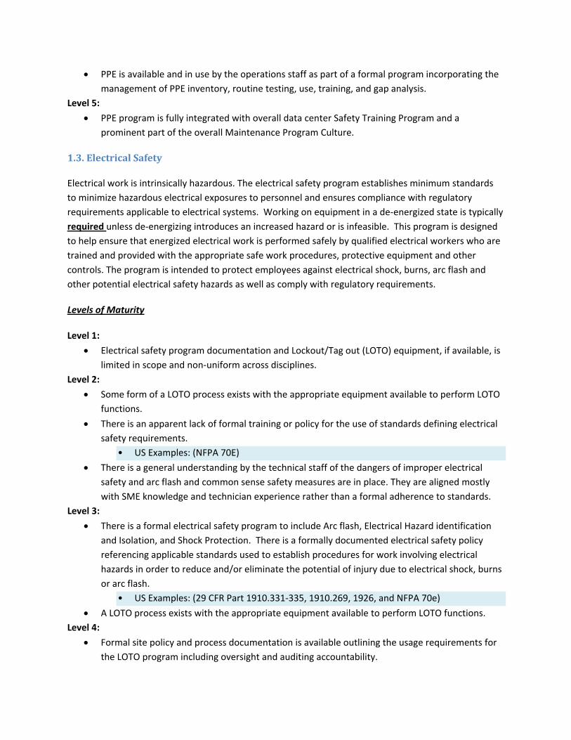
1.3. Electrical Safety
Electrical work is intrinsically hazardous. The electrical safety program establishes minimum standards to minimize hazardous electrical exposures to personnel and ensures compliance with regulatory requirements applicable to electrical systems. Working on equipment in a de‐energized state is typically required unless de‐energizing introduces an increased hazard or is infeasible. This program is designed to help ensure that energized electrical work is performed safely by qualified electrical workers who are trained and provided with the appropriate safe work procedures, protective equipment and other controls. The program is intended to protect employees against electrical shock, burns, arc flash and other potential electrical safety hazards as well as comply with regulatory requirements.
Levels of Maturity
Level 1:
• Electrical safety program documentation and Lockout/Tag out (LOTO) equipment, if available, is limited in scope and non‐uniform across disciplines.
Level 2:
• Some form of a LOTO process exists with the appropriate equipment available to perform LOTO functions.
• There is an apparent lack of formal training or policy for the use of standards defining electrical safety requirements.
• US Examples: (NFPA 70E)
• There is a general understanding by the technical staff of the dangers of improper electrical safety and arc flash and common sense safety measures are in place. They are aligned mostly with SME knowledge and technician experience rather than a formal adherence to standards.
Level 3:
• There is a formal electrical safety program to include Arc flash, Electrical Hazard identification and Isolation, and Shock Protection. There is a formally documented electrical safety policy referencing applicable standards used to establish procedures for work involving electrical hazards in order to reduce and/or eliminate the potential of injury due to electrical shock, burns or arc flash.
• US Examples: (29 CFR Part 1910.331‐335, 1910.269, 1926, and NFPA 70e)
• A LOTO process exists with the appropriate equipment available to perform LOTO functions. Level 4:
• Formal site policy and process documentation is available outlining the usage requirements for the LOTO program including oversight and auditing accountability.

• Arc Flash program is maintained up to date on a periodic basis or as facility electrical distribution system changes are made.
• LOTO process is an integrated part of the overall facility operations program (including training with authorization and certification processes clearly defined) and appropriate action steps are included in MOPs, SOPs, and EOPs.
Level 5:
• Electrical Safety Program training and audits are documented and are conducted annually. Audit results and corrective actions are tracked, as are any identified training deficiencies and corrective actions.
1.4. Hazard Analysis
Establishing safe work procedures starts with hazard analysis. All operational procedures will include a formal hazard analysis, as recommended by OSHA and NFPA. The analysis will identify the job safety risks and assign safety measures for each to attain an acceptable level of risk for carrying out the procedure. Each analysis should identify the following:
• Whether exposure to a hazard exists • The degree of exposure • Whether some type of specific authorization or other control process is needed • Whether PPE is needed • If PPE is needed, what type of PPE will provide the necessary protection
Levels of Maturity
Level 1:
• Hazard analysis is rarely conducted for any type of operational procedure or process at the facility.
• A common sense approach is generally taken when it comes to hazards related to any type of operational procedure performed.
Level 2:
• Informal Hazard Analysis is performed before large operational activities. The informal analysis will consist of discussions and awareness of hazards related to operational activities.
Level 3:
• A formal Hazard Analysis, consisting of documented awareness of related hazards, is performed before operational activities that are considered high risk to uptime or personal safety.
Level 4:
• A policy is documented to ensure that all operational procedures will include a hazard analysis.
• CMMS is used to track level of risk determinations and hazard levels associated with all routine Facility Operations operational and maintenance tasks.
Level 5:
• All operational procedures include a formal hazard analysis as standard.
• The analysis for each operational and/or maintenance item is used to assign safety measures for each identified risk to attain an acceptable level of risk for carrying out each procedure.

1.5. Hazard Communications
The Facility Operations team shall maintain a hazard communications program that complies with the AHJ. The program will apply to all work operations where employees may be exposed to hazardous substances under normal or emergency working conditions. Program components will include:
• Compilation of a hazardous chemical list • The use of safety data sheets (SDS) • Proper labeling of all hazardous materials containers • Employee training on the hazardous properties of chemicals with which they work, safe
handling procedures, and measures to take to protect themselves from those chemicals.
• (US Example: OSHA Hazard Communication Standard, Title 29 Code of Federal Regulations 1910.1200)
Levels of Maturity
Level 1:
• SDSs, if available, are non‐centralized and may be difficult to quickly retrieve. Level 2:
• SDSs may exist, though the implementation of a Hazard Communication plan and its use by staff is rudimentary and inconsistent between disciplines.
• The Hazard Communication plan is typically found to consist primarily of SDS sheets stored in an accessible binder, though its intended use and training of its contents is not well understood.
Level 3:
• A formal Hazard Communications program is in place and being utilized by the facility operations team.
• This program generally consists of documentation outlining the usage of SDS sheets for all hazardous substances in any case that an employee may be exposed.
Level 4:
• The program includes employee training on exposure to hazardous substances and provides guidance on how to use SDS information.
Level 5:
• A formal Hazard Communications program is used that is applicable to all work operations where employees may be exposed to hazardous substances under normal or emergency working conditions.
1.6. Hazardous Materials
All hazardous materials (i.e. explosive, flammable, poisonous, radioactive, corrosive or oxidizing substances) will be properly identified, labeled, stored, maintained and utilized, transported and disposed of in conformance with manufacturer’s recommendations, as well as applicable federal, state and local law and ordinances.
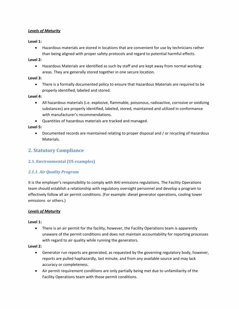
Levels of Maturity
Level 1:
• Hazardous materials are stored in locations that are convenient for use by technicians rather than being aligned with proper safety protocols and regard to potential harmful effects.
Level 2:
• Hazardous Materials are identified as such by staff and are kept away from normal working areas. They are generally stored together in one secure location.
Level 3:
• There is a formally documented policy to ensure that Hazardous Materials are required to be properly identified, labeled and stored.
Level 4:
• All hazardous materials (i.e. explosive, flammable, poisonous, radioactive, corrosive or oxidizing substances) are properly identified, labeled, stored, maintained and utilized in conformance with manufacturer’s recommendations.
• Quantities of hazardous materials are tracked and managed. Level 5:
• Documented records are maintained relating to proper disposal and / or recycling of Hazardous Materials.
2. Statutory Compliance
2.1. Environmental (US examples)
2.1.1. Air Quality Program
It is the employer's responsibility to comply with AHJ emissions regulations. The Facility Operations team should establish a relationship with regulatory oversight personnel and develop a program to effectively follow all air permit conditions. (For example: diesel generator operations, cooling tower emissions or others.)
Levels of Maturity
Level 1:
• There is an air permit for the facility, however, the Facility Operations team is apparently unaware of the permit conditions and does not maintain accountability for reporting processes with regard to air quality while running the generators.
Level 2:
• Generator run reports are generated, as requested by the governing regulatory body, however, reports are pulled haphazardly, last minute, and from any available source and may lack accuracy or completeness.
• Air permit requirement conditions are only partially being met due to unfamiliarity of the Facility Operations team with those permit conditions.

Level 3:
• Generators are equipped with monitoring devices for run hours, operating load and other parameters as required by air permit requirements with adequate access for inspection.
• Monitoring devices are maintained, calibrated and operated IAW MFR recommendations.
• Monthly logs are maintained for each generator to contain information regarding engine run date, start and stop times, cumulative run hours, and reason for run. Monthly logs are available for the periodicity required by the air permit.
• Documentation is maintained, as required by air permits, such as a copy of the air permit itself, fuel receipts and certification reports, service tickets, stack test and VEE reports, records of construction, startup, commissioning, all scheduled and unscheduled maintenance, and any malfunction reports.
Level 4:
• Monitoring devices are tied to EPMS/BMS where all pertinent generator run information, as required by air permit conditions, can be retrieved and prepared into an automated monthly report format.
• CMMS is used to schedule, track, and report all generator service activities to include fuel receipt, scheduled and unscheduled service, malfunctions, and any startup, commissioning, and emissions testing.
Level 5:
• The facility provides training for the Facility Operations staff involved with the generator operations at the facility.
• All records and documents associated with the air permit are retained, stored electronically, and reviewed annually for accuracy and current applicability.
2.1.2. Spill Prevention, Control and Countermeasure Plan
The Spill Prevention, Control, and Countermeasure (SPCC) rule includes requirements for oil spill prevention, preparedness, and response to prevent oil discharges to navigable waters and adjoining shorelines. The rule requires specific facilities to prepare, amend, and implement SPCC Plans. The Facility Operations team maintains the SPCC in accordance with 40 CFR Part 112 and in accordance with state regulations, as applicable.
Levels of Maturity
Level 1:
• A Spill Prevention Control and Countermeasure and Oil Discharge Control Plan has been prepared and certified by a PE (as required) for the facility to address the facility storage, handling and usage of oil. The Facility Operations team is apparently unaware or unaccountable for its use, policies, procedures or upkeep.
Level 2:

• The Facility Operations team is aware of the plan and Spill kits are available where needed. The SPCC may not be updated / maintained and there is still no formal training on the SPCC or spill response.
Level 3:
• The SPCC is maintained and amended as necessary in accordance with 40 CFR Part 112.3.
• Spill kits are available where needed and maintained also. The SPCC and associated spill response procedures has been formally trained to.
Level 4:
• CMMS is used to schedule, track and report all inspections and test records associated with the SPCC and ODCP.
Level 5:
• The facility provides training for the Facility Operations staff involved with the handling, storage and use of oil annually, at a minimum, including actions and procedures associated with the SPCC, and “Lessons Learned” from any spills at the facility. All records and documents associated with the SPCC are retained for at least 5 years, stored electronically, and reviewed annually for accuracy and current applicability.
2.1.3. Tier II Reporting
For any hazardous chemical used or stored in the workplace, facilities must maintain a safety data sheet (SDS), and submit the SDSs (or a list of the chemicals) to their State Emergency Response Commission (SERC), Local Emergency Planning Committee (LEPC) and local fire department. Facilities with chemicals in quantities that equal or exceed the established thresholds must also report an annual inventory of these chemicals by March 1 of each year to their SERC, LEPC and local fire department. Most States require the Tier II form. Tier II forms require basic facility identification information, employee contact information for both emergencies and non‐emergencies, and information about chemicals stored or used at the facility:
• The chemical name or the common name as indicated on the SDS • An estimate of the maximum amount of the chemical present at any time during the
preceding calendar year and the average daily amount • A brief description of the manner of storage of the chemical • The location of the chemical at the facility • An indication of whether the owner of the facility elects to withhold location
information from disclosure to the public
Levels of Maturity
Level 1:
• The Facility Operations team at the site is unaware or unaccountable for SARA Tier II reporting. Level 2:
• Undefined. Level 3:

• The Facility Operations team is aware of the SARA Tier II reporting for the site and has sought out local state requirements. Tier II reports are submitted annually to local fire departments, Local Emergency Planning Committees (LEPC) and State Emergency Response Commissions (SERCs) to help those agencies plan for and respond to chemical emergencies.
Level 4:
• Undefined. Level 5:
• Sara Tier II reporting is optimized using appropriate software removing much or all of the manual effort involved.
2.1.4. Wastewater Discharge Permit or National Pollutant Discharge Elimination System Permit
Any facility that discharges wastewater and/or storm water directly to surface water must obtain a National Pollutant Discharge Elimination System (NPDES) permit, (also known as a wastewater discharge permit) from EPA or the state. Wastewater and storm water discharges are regulated primarily by wastewater discharge permits, which stipulate specific limits and conditions of allowable discharge.
A wastewater discharge permit is required for disposal of waste material into "waters of the state," which include rivers, lakes, streams, and all underground waters and aquifers. A wastewater discharge permit is also required for certain industrial users that discharge industrial waste into sanitary sewer systems.
Levels of Maturity
Level 1:
• The Facility Operations team at the site is unaware or unaccountable for wastewater discharge permit responsibilities.
Level 2:
• Undefined. Level 3:
• The Facility Operations team is aware of and complicit with the wastewater discharge permit requirements for the site.
Level 4:
• Undefined. Level 5:
• Compliance with permit requirements are optimized using appropriate software removing much or all of the manual effort involved.

2.2. Safety (US examples)
2.2.1. OSHA
The Occupational Safety and Health Administration (OSHA)* assures safe and healthful working conditions for working men and women by setting and enforcing standards and by providing training, outreach, education and assistance.
Levels of Maturity
Level 1:
• Evidence of OSHA compliance is limited to little more than the OSHA sign posted in the facility. The poster may not be prominently displayed as required or may be in poor condition.
Level 2:
• The OSHA sign is posted appropriately and is in good condition. The site has an OSHA 300 file for reportable incidents. Management and/or employees are unfamiliar with requirements.
Level 3:
• OSHA is prominently referenced throughout safety program documentation and policies. OSHA required training, recordkeeping and reporting documentation is available for the facility.
Level 4:
• Undefined. Level 5:
• The facility provides OSHA required training for the Facility Operations staff and develops “Lessons Learned” from safety related incidents at the facility. All records and documents associated OSHA reporting are retained for at least 5 years, stored electronically, and reviewed annually for accuracy and current applicability.
2.2.2. NFPA
NFPA develops, publishes, and disseminates more than 300 consensus codes and standards intended to minimize the possibility and effects of fire and other risks.
Levels of Maturity
Level 1:
• Obvious electrical hazards are present in the facility, or electrical/hot work is being performed without appropriate safeguards. Fire extinguishers inspection tags are missing or outdated. Fire suppression system test and inspection documentation is missing or outdated.
Level 2:
• Undefined. Level 3:
• Documentation is available and up to date indicating compliance with NFPA 10 (portable fire extinguishers), NFPA 25 (Inspection, Testing, and Maintenance of Water‐Based Fire Protection Systems), NFPA 70E (Electrical Safety in the Workplace).

Level 4:
• CMMS or other operational support system is used to track, schedule and maintain all reports associated with applicable NFPA required tests and inspections.
Level 5:
• The facility provides training for the Facility Operations staff involved with electrical work, hot work, and/or other work which requires manipulation of the fire suppression systems, and develops “Lessons Learned” from any related incidents at the facility. All records and documents associated with the NFPA are retained for at least 5 years, stored electronically, and reviewed annually for accuracy and current applicability.
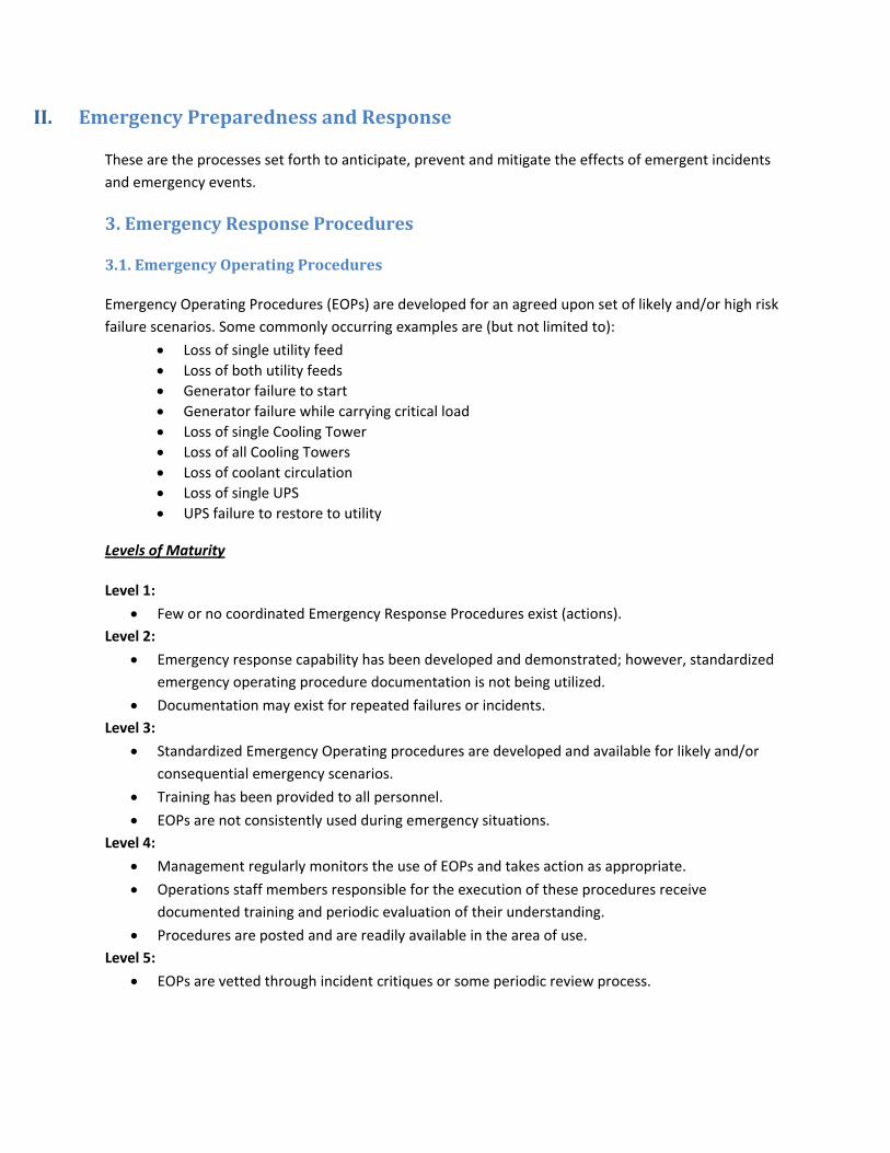
II. Emergency Preparedness and Response
These are the processes set forth to anticipate, prevent and mitigate the effects of emergent incidents and emergency events.
3. Emergency Response Procedures
3.1. Emergency Operating Procedures
Emergency Operating Procedures (EOPs) are developed for an agreed upon set of likely and/or high risk failure scenarios. Some commonly occurring examples are (but not limited to):
• Loss of single utility feed • Loss of both utility feeds • Generator failure to start • Generator failure while carrying critical load • Loss of single Cooling Tower • Loss of all Cooling Towers • Loss of coolant circulation • Loss of single UPS • UPS failure to restore to utility
Levels of Maturity
Level 1:
• Few or no coordinated Emergency Response Procedures exist (actions). Level 2:
• Emergency response capability has been developed and demonstrated; however, standardized emergency operating procedure documentation is not being utilized.
• Documentation may exist for repeated failures or incidents. Level 3:
• Standardized Emergency Operating procedures are developed and available for likely and/or consequential emergency scenarios.
• Training has been provided to all personnel.
• EOPs are not consistently used during emergency situations. Level 4:
• Management regularly monitors the use of EOPs and takes action as appropriate.
• Operations staff members responsible for the execution of these procedures receive documented training and periodic evaluation of their understanding.
• Procedures are posted and are readily available in the area of use. Level 5:
• EOPs are vetted through incident critiques or some periodic review process.

3.2. Crisis Management Plan
A crisis is defined as a situation of extreme difficulty, which is outside the scope of prepared responses. In the data center environment, many emergency scenarios are prepared for with written procedures and practice drills, but it is not uncommon to experience unanticipated events or malfunctions.
Crises can be prolonged and have the potential to develop into more serious events when not handled in a coordinated manner by all data center personnel. In order to minimize their impact, a Crisis Management plan is developed by the Facility Operations team in coordination with Customer management. Specific consideration should be given to fuel procurement policies during natural disasters as well as generator maintenance procedures and polices during periods of extended generator operations,
The plan should contain the following elements: A. Preparation and Prevention ‐ The set of activities undertaken to reduce the chance of a crisis
happening, or reduce the damaging effects. B. Crisis Management Program ‐ The detailed plan of action on what to do in the event of a crisis
situation. C. Crisis Plan Implementation Procedures ‐ The procedures that are used to put the CMP into
effect. D. Crisis Response Training ‐ The procedures outlining the continued maintenance, testing and
training requirements of the plan.
Levels of Maturity
Level 1:
• Over reliance on system redundancies and facility resilience or on the knowledge and strengths of the operational team foster a sense of “that can’t happen here.”
• Crisis response/communication is inefficient or ineffective. Solution development with regard to crisis events is slow. Facility Operations teams regard transparency with fear, which hinders customer relations.
Level 2:
• Crisis Management is a reactive process that is outlined with basic steps to be enacted after a crisis has been identified.
Level 3:
• Crisis Management plan is documented and contains the detailed plan of action on what to do in the event of a crisis situation, and the procedures that are used to put the CMP into effect. Crisis Response Training is provided and outlines the continued maintenance, testing and training requirements of the plan.
Level 4:
• Operations staff members responsible for the execution of these procedures receive documented training and periodic evaluation of their understanding.
• Procedures are readily available. Level 5:

• Management optimizes the CMP through regularly scheduled reviews/rehearsals of the Crisis Management Plan
3.3. Business Continuity/Disaster Recovery Procedures
The emergency response plan is intended for use by Facility employees to prepare for and respond to emergency conditions. Emergency Coordinators are required to have a working knowledge of the procedures described in the Plan. Also, proper attention to the fundamental response concepts can mitigate emergencies that may develop.
The objectives of the emergency response plan are to:
• Protect human life, health and safety. • Limit and contain damage to the facility and the equipment therein. • Stabilize Operations and Services. • Effectively manage communications throughout the incident.
The business continuity plan is intended to provide guidance for the quick and effective recovery of critical business functions following any event that causes the loss or limited use of data center facilities and services.
The objectives of the business continuity plan are to:
• Minimize financial and operational impact resulting from a short term or long‐term loss of facilities, technology or communications equipment;
• Prioritize mission‐critical functions that require immediate restoration; • Identify the key resources and dependencies for critical functions; and • Serve as the guiding document for each business units’ individual business continuity plans.
Levels of Maturity
Level 1:
• Solution implementation is uncoordinated and slow.
• Communication with customers/outside parties is misleading or untruthful or improperly managed.
• Health and Safety related issues are improperly prioritized against facility/equipment issues or the reputation of the organization.
Level 2:
• Disaster recovery scenarios have been identified for procedure development as a response to recent experienced or recently publicized events.
• Business Continuity is a reactive process that is outlined with basic steps to be enacted after a service disruption has occurred.
Level 3:
• A formal Disaster Recovery plan, with included procedures for likely disaster scenarios for the region in which the facility is located, is documented and available to site operations staff.

• The plan includes training specifics and detailed step by step plans of immediate actions in the event of any prescribed local disaster event.
• A formal Business Continuity Plan is documented and available to the operations staff which includes detailed steps for coordination of business resumption and system restoration activities following a data center service disruption.
Level 4:
• Undefined. Level 5:
• The Disaster recovery plan is documented and contains the following elements at a minimum: o Program Overview ‐ The detailed plan of action on what to do in the event of a
disaster. o Disaster Recovery Procedures ‐ Developed for all possibly conceived disasters. o Training ‐ The procedures outlining the continued maintenance, testing and
training requirements of the plan. o Preparation and Prevention ‐ The set of activities undertaken to reduce the
chance of a disaster happening, or reduce the damaging effects.
• The business continuity plan is an integrated part of the crisis management and/or disaster recovery plan and provides a fully documented process for planning and implementing the resumption of time‐sensitive operations immediately following an emergency, interruption, or disaster.
• The executive team works with the Critical Facility manager, local public safety agencies, and public media outlets, as required, to accomplish business resumption activities
4. Scenario Drills
4.1. Drill Process, Procedure, Scheduling and Execution
In order to enhance operational readiness, the practice of EOPs should be administered on an individual basis to exercise the staff’s abilities and evaluate their responses. Drills should be scripted, documented and contain a performance evaluation. An agreed upon schedule should be established to specify which drills to run in a particular month or quarter that aligns with the overall facility priorities and readiness requirements.
Levels of Maturity
Level 1:
• Scenario drills on critical infrastructure systems are not being conducted. (Fire drills and other EHS related drills are not applicable.)
Level 2:
• Scenario drills are being conducted; however, standardized drill documentation is not being utilized.

• Focus of drills is on experienced failure or incidents, but is not the same as actual emergency response.
Level 3:
• Standardized Emergency Drill format and process has been established.
• Drills are identified, scheduled and performed on a regular basis. Level 4:
• Drills are evaluated at the individual and at the group level.
• Drill results are used to determine team readiness and identify training gaps. Level 5:
• Records are maintained of shortcomings in drill performance are remedied through: ‐ remedial training ‐ procedure modification ‐ drill re‐performance
5. Incident Management
5.1. Notification
There are three distinct escalation protocols to be followed; Facility, FO Team and Third‐party.
Facility Event: An escalation list should be maintained containing contact information for all Customer and Facility Operations personnel in the escalation chain. The list will be sorted in contact order and will indicate which personnel to contact for each individual event classification. There will be an associated event escalation procedure, to include a routine for performing escalation drills. A drill will be performed quarterly to verify the process.
FO Team: There will be a procedure for escalating issues within the FM Contractor organization. An escalation chart will be provided to Customer showing escalation intervals and contacts for the following priority levels:
• Priority 1 – Emergency events, critical information requests, urgent service requests.
• Priority 2 – Standard service and information requests.
• Priority 3 – Proposals, special information requests, non‐time sensitive projects.
Third Party: There will be a procedure for escalating service issues within third‐party vendor organizations. An escalation list will be created for each third‐party service organization showing escalation intervals and contacts, to be invoked when service issues are not resolved in the required time frames.
Levels of Maturity
Level 1:
• Site personnel typically call supervisors. Notification may be unidirectional. Level 2:
• Informal processes exist with regard to incident notification.
• Contact information is available in some format such as company address book; however, it is not organized in an incident escalation list.
Level 3:
• Escalation Procedures are documented that outline contact requirements for specific situations related to data center operations.
• An updated list of current stakeholders and response personnel is available to the operations team for escalation events.
Level 4:
• Escalation process is regularly rehearsed and modified as needed.
• Procedures include all severity levels that are required to be escalated and stipulate expected time requirements for those notifications to be made.
Level 5:
• A comprehensive flow chart illustrating escalation hierarchy is in place and posted in appropriate operational areas.
• A refined escalation process exists as a result of continuous improvement.
5.2. Incident Identification and Reporting
An incident can be defined as:
• Any specific event that directly and immediately impacts the functionality of the Critical Facility. • Any specific event that compromises the safety of an individual within the Critical Facility and its
environs. • The failure of any equipment or service that jeopardizes the normal operation of the Critical
Facility
All incidents should be reported immediately once the situation is stabilized. A brief summary of the incident would be sent to the appropriate distribution list as defined by the incident level of severity. Within 24 hours of the incident, a full Incident Report should be filed that contains a detailed, step‐by‐step, chronological description of the incident that clearly identifies facts such as:
• The start time • Who discovered it • Who was present • What the initial response was • Who was notified • How the situation was stabilized • What resources were brought to bear • The eventual resolution (when applicable) • The time that each step in the narrative occurred
Levels of Maturity
Level 1:
• Inconsistent or informal reporting takes place.

Level 2:
• No formal definition of an incident is available.
• Non‐standardized or informal reports are utilized. Level 3:
• A formal definition of an incident is available.
• A standardized reporting template or system is available for use.
• An incident reporting process is documented and is used for operational and training purposes.
• A policy is in place mandating the use of incident reports for qualifying incidents. Level 4:
• Archived or auditable history of past reports is available for review.
• Pertinent information from incident reports is recorded in a spreadsheet or database for management review and analysis.
• Incident reporting timeframes are established.
• Incident follow up action items are also documented and tracked for follow up. Level 5:
• Automation is used in the incident reporting process to achieve repeatability, accuracy and efficiency.
• A refined incident reporting process exists as a result of continuous improvement.
5.3. “Lessons Learned”/Near miss reporting
When incidents or near misses occur, any “Lessons Learned” that will help prevent future occurrences must be fully documented to use as a training and reference tool.
Levels of Maturity
Level 1:
• A “Lessons Learned” process is not evident.
• A near miss program is not evident. Level 2:
• Examples of “Lessons Learned” are referenced or provided but are not backed up with standardized documentation.
• Near misses occur without recognition of significance or the need for reporting. Level 3:
• Failure analysis is conducted for all defined incidents.
• Reports are in a centrally accessible location for all team members to access and review for “Lessons Learned”.
• Involved team members are educated in “Lessons Learned”; however, information is not shared across the entire team.
Level 4:
• “Lessons Learned” are fully documented to use as a training and reference tool.

• A “Lessons Learned” reporting tool is available for significant incidents and is distributed to applicable stakeholders.
• A process exists for the “Lessons Learned” and near miss programs. Level 5:
• Automation is used in the “Lessons Learned”/near miss process to achieve repeatability, accuracy and efficiency.
• A refined “Lessons Learned”/near miss process exists as a result of continuous improvement.

III. Maintenance Management
Tasks associated with the upkeep, maintenance and repair of the physical infrastructure systems in support of the facility performance, reliability and service level objectives.
6. Asset Management
6.1. Asset Database
The asset database should contain a comprehensive and current list of all critical facility equipment. The level of detail should be at the discrete system level. Sub‐assemblies do not need to be listed separately. For example, a cooling tower would be listed, as well as the associated condenser water pumps. However a spray pump which is part of the cooling tower assembly would not be listed separately. UPS battery cabinets are considered separately from the UPS itself, but individual batteries are not listed.
At a minimum, the asset database will contain the following information:
• Asset ID: Unique identifier for each asset • Type: Top level classification ( i.e. Electrical, Mechanical, Fire System) • Sub‐Type: Second level classification (i.e. PDU, CRAH, VESDA) • Description: Text description of asset • Make: Asset manufacturer • Model: Manufacturer’s model number • Size: Asset size or rating • Location: Location ID (room or area) • Trade: Trade responsible for asset maintenance • Serial No: Manufacturer’s serial number • Install Date: Date asset was put into service • Warranty Exp: Warranty expiration date • Replace By: Estimated asset replacement date
Levels of Maturity
Level 1:
• Asset information is loosely organized in a variety of documents. Level 2:
• Assets are centrally recorded in a list or database and updated on an as needed basis.
• The asset list is comprehensive of all critical facility equipment.
• Asset information is current and accurate.
• Asset data includes ID, Make, Model, Serial Number and Location. Level 3:
• An Asset Management Process has been documented that specifies the format of the asset database/list, the asset attributes to be recorded, updating procedures and audit requirements.
Level 4:
• Asset audits are conducted a minimum of once a year and are documented.
• Asset data includes installation date*, size or rating, warranty expiration date*, projected end of life date and trade/vendor responsible for maintenance.
• A documented process exists for referencing the warranty data before conducting corrective maintenance.
• A documented process exists for using end of life data for forecasting and budgeting. * May be incomplete for legacy assets.
Level 5:
• All critical facility infrastructure assets are tracked using a Computerized Maintenance Management System (CMMS) or an equivalent software application.
• Standardized asset reports are available that are suitable for auditing purposes.
6.2. Scopes of Service
Each unique piece of equipment on the equipment list must have a detailed Scope of Service (“SOS”) associated with it. The SOS contains information about the maintenance frequency and the maintenance types. For example, a CRAH unit may be serviced 12 times a year, with one annual, three quarterly and 8 monthly maintenance events. The SOS also contains the amount of time allocated to perform the maintenance, in man‐hours.
Each maintenance type should have a detailed list of the specific activities associated with it. The level of detail should be at the task level. For example, “Check filters” would be a task level activity. Removing a cover to get to the filter would be unnecessary detail for this purpose. On the other hand, “Check all operational parameters” would be too little detail to accurately specify the service.
A fully qualified scope of service is referenced to some industry standard (e.g. IEEE 446 or NETA MTS) and compiles information from a variety of other sources to create a maintenance program that emphasizes prevention over repair. It needs to take into account the manufacturer’s recommended maintenance, equipment history, the experience of site operations personnel, vendor recommendations and any other available information.
Ideally, the SOS for each piece of equipment is listed in a master document that is checked periodically for completeness and accuracy. Information gathered during the maintenance process should be mined for improvement to the SOS on a regular basis, preferably as part of a formal quality improvement process.
Levels of Maturity
Level 1:
• Preventative and/or predictive maintenance are performed solely at the discretion of the OEM and third‐party maintenance vendors, or by in‐house technicians using their acquired knowledge.
• Maintenance is often reactive in nature rather than conducted using a proactive Preventative Maintenance program.
Level 2:
• Preventative Maintenance is being performed on all critical facility equipment.
• Maintenance steps are listed in vendor or internal work order documentation.
• Significant variations exist in the way maintenance procedures are being performed between occurrences.
Level 3:
• The data center owner/operator has documented their own standards for maintenance frequency and the tasks required for each maintenance event as a Scope of Service based on manufacturer's recommendations, industry best practices, “Lessons Learned”, vendor input and the combined experience of the facility team.
• There is continuity of information between the documented Scope of Service, vendor contract (if applicable) and maintenance procedures (e.g. work order tasks or MOP).
• There is demonstrated adherence to the work tasks in the work order documentation (e.g. properly filled out, detailed service reports, work orders or procedures).
Level 4:
• There is a documented process for evaluating maintenance activity feedback and work order analysis to optimize the Preventative and Predictive Maintenance procedures, and to modify the associated Scope of Service documentation.
Level 5:
• Scopes of Service are integrated into the CMMS PM schedules and work order tasks.
• Predictive Maintenance and other Reliability Centered Maintenance techniques are being used to increase equipment reliability and lower the total maintenance cost.
7. Work Order Management
7.1. Scheduling & Tracking
A well‐organized maintenance schedule is a key component to equipment reliability and system availability. Maintenance scheduling should be done in the CMMS, if possible, to include all critical infrastructure assets. The schedule should be based on manufacturer’s recommendations, site conditions, equipment history, industry standards and best practices. All work must be coordinated with other site activity and synchronized with personnel schedules to ensure that adequate skilled manpower is available.
The maintenance schedule must be reviewed with Customer management on a regularly scheduled periodic basis. Annual maintenance planning should include the addition to, deletion or modification of existing maintenance routines.
Work orders track all of the time and activities associated with each maintenance event, including administrative time (e.g. preparing a MOP) from scheduling through work completion. If possible, the time on task and administrative time should be tracked in separate fields in the work order to facilitate

work analysis. All maintenance evolution work orders should track for on‐time completion rates, failure codes, assigned personnel and other criteria to facilitate work analysis and reporting.
Levels of Maturity
Level 1:
• Maintenance scheduling is reactive to system or equipment failures or in accordance with vendor provided timeframes.
• If a work order system is available, utilization is sporadic and non‐uniform across the disciplines. Level 2:
• The preventive maintenance schedule is tracked through the use of a rudimentary process or system that relies heavily on singular individuals or is prone to error. The performance of scheduling may be the responsibility of the respective SMEs without standardization between the trades / disciplines in how they are handled. Missed maintenance items may be present and even be considered acceptable. Note that while the use of a CMMS is usually indicative of a higher level of maturity, the existence of one does not automatically upgrade maturity level.
• Installation and Maintenance work orders are created manually.
• Corrective maintenance activities are often separate from installation / maintenance activities and may not be incorporated or tracked as part of the manual work order system.
Level 3:
• Coordination between disciplines / SMEs is standard and scheduling practices are collaborative. Proper scheduling training is given as part of the respective qualification processes. Missed maintenance items may occur occasionally due to system limitations and are treated as serious incidents (and documented as so) rather than commonplace or acceptable. The Maintenance schedule is based on manufacturer's recommendations, industry standards and SME experience / familiarity. Some basic CMMS systems / functionality may be present but its use may be limited or even considered counterproductive in some ways.
• Installation, Maintenance, and Corrective Maintenance activity work orders are part of the site CMMS system.
Level 4:
• Maintenance scheduling is tracked and reconciled; and missed activities are nonexistent or extremely rare.
• All maintenance activities are tracked for on‐time completion rates and work history with continuous improvement being top priority.
Level 5:
• Maintenance scheduling is conducted via a CMMS that includes all critical infrastructure assets and is considered a helpful utility rather than a cumbersome requirement.
• All work scheduling is coordinated with other site activity and synchronized with personnel schedules to ensure that adequate skilled manpower is available and proper event response personnel are present if necessary.
• The maintenance schedule is reviewed with Customer management on a routine and mutually agreed upon basis.

• Annual maintenance planning will include the addition to, deletion of or modification of existing maintenance routines.
• All vendors scheduling is done at least a month in advance.
• Work orders track all of the time associated with the maintenance activity, including administrative time (e.g. preparing a MOP). Time on task, administrative time, and failure codes, should be tracked in the work order to facilitate work analysis and reporting.
7.2. Recording and Analysis
Levels of Maturity
Level 1:
• Material History and maintenance records are loosely organized and difficult to retrieve in a timely manner. This information is often found solely in the comments in vendor service reports.
Level 2:
• Maintenance history is mostly organized through the storage of vendor service reports. Most of the time, only findings leading to required corrective / follow‐on activities are extracted from the performance of maintenance, with trend analysis being occasional and non‐standard.
Level 3:
• A formalized process exists for the extraction of major findings and historic trend analysis from the performance of evolutions and maintenance though deviations may occur between technicians due to immature or non‐standard practices to ensure common adherence to the process.
Level 4:
• Consistency exists for all technicians in material history and maintenance records, with management measuring and monitoring adherence to processes and helping to drive continuous improvement. The use of IT systems to facilitate this continuous improvement may be fragmented or a low priority.
Level 5:
• Findings from material history and maintenance records are an integral and essential piece to maintenance performance to such an extent that technicians may not even understand that there is a distinction between recording material history, maintenance performance, follow‐up, and trend analysis. IT systems are usually an integral part of this process; and in some cases mature data analytic services / software are found.
7.3 Corrective or Followon Activities
Levels of Maturity
Level 1:
• Corrective or follow‐on maintenance items found before, during, or as the result of the performance of scheduled maintenance activities are not treated independently. All follow‐on work is tracked as part of the initial work order keeping tickets open sometimes indefinitely.

Level 2:
• Corrective or follow‐on maintenance items found before, during, or as the result of the performance of scheduled maintenance activities are stand‐alone work orders generated on an as needed basis and are not associated with any installation or maintenance activity.
Level 3:
• Corrective maintenance actions that are triggered by discoveries made during preventative maintenance activities are usually tracked in child work orders under the original PM work order.
Level 4:
• All Corrective maintenance actions that are triggered by discoveries made during preventative maintenance activities are tracked for commonly failed components, completion times, percentage of all maintenance that is follow‐on work, and work history.
• All follow‐on activities are tracked in a work order module of the CMMS system. Level 5:
• Work orders will track all of the time associated with the maintenance activity, including administrative time (e.g. preparing a MOP). If possible, the time on task and administrative time should be tracked in separate fields in the work order to facilitate work analysis.
7.4. Reporting
Levels of Maturity
Level 1:
• Reports may be non‐standard and / or handled simply as in‐person updates or informal emails from requesting parties. Some may be standard but are usually simply requests for specific status from management.
Level 2:
• Reports are usually manually generated and vary based on the SME providing them. Reports are often provided as a general course with some level of periodicity instead of on a per‐request basis.
Level 3:
• Manual reports can be pulled by CFM or local system administrators based on existing templates. Report‐building functionality occurs on an immediate or as‐needed basis or with very little manual effort by CFMs or SMEs.
Level 4:
• CMMS is configured to be able to automatically generate and escalate reports specific to the data tracked and trended with regard to all pieces of critical system equipment.
Level 5:
• CMMS is integrated with DCIM system (or equivalents) to provide real‐time, up‐to‐the‐minute reporting data. Reports are automatically generated and sent out on a regular basis. Baseline operation may be established with deviations from normal operating conditions generating applicable reports.

8. Computerized Maintenance Management System
The Facility Operations team should consider the use of a suitable Computerized Maintenance Management System (CMMS) for asset management, maintenance scheduling, work order management, inventory management, labor utilization and tracking, and management reporting.
The CMMS should be used for automatic scheduling and tracking of all preventative maintenance activities. Notifications will be provided prior to maintenance events and deviations from the schedule will be recorded and reported on. Labor will be tracked and analyzed to determine total utilization, time spent on corrective vs. preventative maintenance, and craft requirements. Spare parts will be managed through the work order process and restocking levels flagged automatically. Equipment information will be collected and analyzed to detect trends and problem areas. Reports will be generated to help quantify and manage the maintenance process.
8.1. Administration
Levels of Maturity
Level 1:
• FO staff is overwhelmed or under‐informed with regard to the administration of the CMMS. Level 2:
• Some members of the FO staff are using CMMS for some specific activities. Use of and application of the system is not uniform across the team.
Level 3:
• Defined business processes (work flows, roles and responsibilities) are specifically developed. Training modules are available for CMMS administration.
• There are clearly defined business goals relating to the use and application of the CMMS. Level 4:
• Executive management and the Facility Operations team are committed to the implementation, use and integration of the CMMS.
• FO Staff is provided dedicated training on input, function, and maintenance for the CMMS. Level 5:
• There is a full time on site system administrator who “champions” its continued use.
• The Facility Operations staff is fully proficient in the control, management, and navigation of the CMMS system.
8.2. Utilization
Levels of Maturity
Level 1:
• FO staff is demonstrates unfamiliarity familiarity with CMMS application. Level 2:

• CMMS is limited in utility. Installation and maintenance work order management only.
• FO team is focused on “fixing efficiency”. Downtime and overhauls are scheduled. CMMS is used primarily for planning, and scheduling the maintenance.
Level 3:
• Utilization of the system is built around business goals.
• CMMS contains current comprehensive equipment list and is being used to manage the preventive maintenance schedule.
• . Level 4:
• Initial business goals set forth regarding CMMS utilization have been mastered and additional modules, functions are being explored.
• CMMS is used to track labor, spare parts, and PM completion.
• The CMMS is being used to track equipment failure data, as well as technician remarks about each work order.
• Spare parts restocking levels are flagged and escalated; Equipment information is collected and analyzed, trends detected and problem areas escalated.
Level 5:
• After the manufacturer’s warranty period, the maintenance scopes of work and intervals are determined by analyzing actual data from the CMMS work order history via RCM or a similar analytical process. (Manufacturer’s recommendations are considered, but not followed blindly.)
• CMMS is fully utilized to optimize the operation of the equipment, save energy costs, and increase facility reliability. Reduction in maintenance costs are being tracked, as well as, reduction in numbers of "break‐fixes," and reduction in equipment downtime.
8.3. Functionality
Levels of Maturity
Level 1:
• Undefined. Level 2:
• CMMS is homegrown or commercial. Emphasis on making the organization fit the CMMS rather than making the CMMS fit the needs/business goals of the organization.
Level 3:
• Commercially developed or extremely robust homegrown system with modules for asset management, work order management, scheduling, and inventory control.
Level 4:
• Dashboards are available and utilized across data center teams allowing IT and other groups access to asset and maintenance information to enhance coordinated IT/FO work activities to improve change control processes.
Level 5:

• CMMS programs can interface with existing energy management and control systems and building management systems. Coupling these capabilities allows condition‐based monitoring and the generation of component energy use profiles.
9. Vendor Management
9.1. Selection
It is important to focus maintenance subcontractors’ attention on prevention over repair. Even experienced, well‐meaning vendors will by nature only expend so much effort on preventative and predictive maintenance. Since they are likely to get additional break‐fix work if there is an equipment failure, there is simply no mechanism built into a normal PM contract process to give them the incentive to do otherwise. Furthermore, the competitive bid process often forces vendors to specify a minimal level of preventative maintenance in order to keep their costs low enough to win the contract. This is contrary to the goals of a mission critical facility operation, and must be countered with specific measures.
The subcontractor selection process begins with establishing a solid Scope of Work (SOW) for each contract, which is derived from the Scope of Service for the assets being serviced. A detailed SOW helps keep the playing field both high and level. Good companies will appreciate the opportunity to price out a high quality PM program, knowing that the competition will be held to the same standard.
Good communications with potential vendors is essential. They need to understand that they are dealing with a culture of excellence with an emphasis on prevention and reliability. It should be noted that contracts will be awarded to the company with the best value, based on the expectation that good preventative and predictive maintenance will lower the cost of corrective maintenance and enhance reliability.
A good Request for Proposal (RFP) is a valuable tool for evaluating vendor bids. It should contain the following items:
• A complete list for the equipment to be serviced • A detailed Scope of Work for each equipment type • Working Hours • Facility Work Rules • Rates for out‐of‐scope work (Straight time, Overtime, Sunday/Holiday and Travel time) • Truck fees • Expected duration for each maintenance type (i.e. Quarterly, Annual, etc.) • List of exclusions • List of additional recommended maintenance with frequency and cost • Cost for specified term (typically 1 year)
The final contract should contain all of the information contained in the RFP, especially the equipment list and SOW.

Qualified vendors must be subject matter experts on the equipment that they will be servicing, and must be able to demonstrate their experience through referrals. Personnel sent to the site must possess all required licenses and certifications to perform work. An attempt should be made to ascertain the bench strength of the organization to ensure that more than one or two qualified personnel exist in the region. Experience in other mission critical environments is a good indicator that they are used to working with critical facility work rules and understand the sensitivity of the installation.
Levels of Maturity
Level 1:
• Vendors are called on a case by case basis after an incident or need for service. RFPs are sometimes hastily drafted emails lacking a clear scope of work and are sent to the first called vendor to answer.
• Vendor Selection may fall under another department than the Facility Operations team. Level 2:
• Equipment SOWs are provided by vendors without formal RFP and are not benchmarked against industry best practices or OEM recommendations.
• RFPs are drafted as service needs are recognized, but not necessarily as a response to an incident.
• Vendors are selected haphazardly through internet search, rather than based on thorough research for best reputation/value or through competitive bid process.
• Vendor contracts are in place for critical systems only. Level 3:
• Formally drafted RFP incorporates equipment SOW provided by OEM and benchmarked against industry best practices.
• RFPs are manually tracked and saved for future use.
• RFPs are sent to multiple vendors.
• Contract bids are compared against SOW.
• Vendor contracts are in place for major systems. Level 4:
• Formal RFPs are prepared IAW engineering approved SOW, saved in CMMS and sent to multiple reputable vendors.
• Received contract bids are tracked and compared against SOW and against each other for best price/value
Level 5:
• RFPs and associated SOW/SOS are reviewed by engineering annually or following work as part of QC process, gaps are identified and addressed.
• Vendor contracts are in place for equipment/systems where SOWs cannot be reasonably completed by in‐house staff, are up to date and maintained electronically. Contract SOWs are reviewed annually.

9.2. Performance Metrics
Selecting and managing third‐party vendors that perform on‐site services are important responsibilities of the Facility Operations team. It is vital that the vendor representatives understand and buy into the facility change management processes. In practical terms, this means that any vendor technician or subcontractor that steps foot in the facility abides by the Critical Facility Work Rules. While all of the work rules are all important, those dealing with MOP work are the lynchpin of the change control process and are often the most contentious aspect of vendor relations. The most common issues in this regard are:
• Lack of communication about the process between vendor management and the individual technicians sent on‐site. This results in technicians showing up to work that have no concept of how the process functions.
• Resistance to working under supervision. Some technicians do not like anyone to watch them work and don’t understand why it’s done.
• Refusal to acknowledge the leadership role of the FM Contractor Supervisor. This is particularly prevalent when the vendor contracts directly to the client, and/or they have a history of working at the location without supervision.
It is the responsibility of the Facility Operations team to understand and deal with these issues to ensure that all vendor personnel abide by the letter and intent of the facility work rules and change processes. It is highly encouraged that KPIs be established with third‐party vendor companies to help establish a strong line of communication and a basis for process improvement.
Levels of Maturity
Level 1:
• Work scopes, MOPs, work rules, and other guidelines for work done by vendors are non‐existent or not used.
Level 2:
• "Trusted" vendors are not necessarily expected to follow a documented work scope or method of procedure.
Level 3:
• All vendors are expected to follow a documented work procedure. Level 4:
Specifically detailed contract items are tied to mutually agreed‐upon KPIs. All vendors are expected to sign and abide by critical facility work rules and to follow a documented work procedure.
Level 5:
• The agreed upon KPIs are regularly reviewed after a contracted service call.

9.3. Vendor Service Reports
Vendor Service Reports (VSRs) are important source documents for detailed records of maintenance activities. The information that they provide must be critically examined and preserved for future reference. VSRs should be collected from vendors at the time of service, unless the information needs to be processed off‐site first. When a VSR is received, the following steps need to be taken:
• Review the report for completeness, legibility and any obvious errors. • Compare to previous reports to identify unexpected changes. • Note any variances, comments or recommended actions. • Enter info into Work Order Management System • Make an electronic copy • File the hardcopy
Levels of Maturity
Level 1:
• Vendor service reports, if received, are occasionally given a cursory glance and are not likely to be reviewed for accuracy, completeness of work, outstanding issues, etc.
Level 2:
• Vendor service reports are reviewed for outstanding issues, but not likely to be compared to contract SOW to ensure adherence to contractual obligations.
Level 3:
• Vendor service reports are collected for all service calls and reviewed for accuracy, completeness of work, scope of work adherence, outstanding issues and recommendations.
• The vendor service reports are kept and filed manually or electronically. Level 4:
• The vendor service reports are stored in CMMS and tracked under appropriate piece of equipment or system.
Level 5:
• Key metrics, data, trends, or other findings are extracted from service reports and are analyzed for continuous improvement as part of a standardized data analytics / data science approach.
10. Spare Parts Management
10.1. Identification
Prior to the start of operations, an evaluation should be performed to build a recommended spares list that is derived from manufacturer and vendor recommendations, specific mission goals, plant design, parts availability and past experience. Frequently used items may also be stocked to take advantage of bulk discounts. Re‐evaluation of the spares inventory for item selection and stocking levels should take place on an annual basis. As equipment ages, the likelihood of component failure increases while parts availability can decrease, which along with maintenance history may affect the decision on which items to stock, in what quantities.

Levels of Maturity
Level 1:
• Spare parts identification is not a priority or it is expected that service personnel will maintain standard spare parts.
Level 2:
• Undefined. Level 3:
• A single spare part database is available and is based on manufacturer's recommendations, industry standards and SME experience / familiarity with systems/equipment.
Level 4:
• Undefined. Level 5:
• Spare parts list is further refined including environmental concerns, seasonal logistics, etc.
10.2. Inventory and Storage
A spare parts inventory should exist for select components that may have procurement intervals that exceed the maximum acceptable downtime for a particular system. The spares inventory should be integrated into the Computerized Maintenance Management System (CMMS), taking advantage of the ability to perform automatic adjustment of inventory levels as components are utilized in maintenance activities. The system should be used to flag a component for reorder when inventory levels reach a predetermined threshold. When applicable, the CMMS will be used to track parts availability across multiple facilities, and facilitating the analysis of stocking levels, repair costs and purchasing strategies.
Spare parts must be kept in a safe, clean, and stable environment on site until needed for routine or emergency replacement. Facility Operations team should track when spares reach minimum levels in sufficient time to process and order replacements.
Quality assurance is an important aspect of spares management. All spares should be inspected upon receipt to ensure their suitability for use, condition and quantity received. When possible, quality control checks should be performed to verify proper working order. Critical spares kept in storage should be periodically inspected and/or tested (when possible) to ensure their continued viability. Prior to being put into service, a final inspection and/or testing procedure should take place to ensure that the part is appropriate and fit for service.
Levels of Maturity
Level 1:
• Few, if any, identified spares have been procured or may be expected to be available through contract mandates.
Level 2:

• Critical spare parts associated with major system equipment like UPS, Generator, and Chillers are contractually maintained off site by OEM vendor or 3rd party service providers.
Level 3:
• Spare parts associated with major system equipment like UPS, Generator, and Chillers are maintained on site by the operations team.
• The spare parts inventory consists primarily of spare parts kits recommended by the OEM vendor.
Level 4:
• The spares inventory is proactively managed for the adjustment of inventory levels as components are utilized in maintenance activities.
• Spare parts are kept in a safe, clean, and stable environment provided on site, until needed for routine or emergency replacement.
• All spares are inspected upon receipt to ensure their suitability for use, condition and quantity received. Critical spares kept in storage are periodically inspected and/or tested (when possible) to ensure their continued viability.
Level 5:
• The spares inventory is integrated into the Computerized Maintenance Management System (CMMS), taking advantage of the ability to perform automatic adjustment of inventory levels as components are utilized in maintenance activities. The system is used to flag a component for reorder when inventory evels reach a predetermined threshold. l

IV. Site Management
Day‐to‐day activities associated with site utilization, performance and efficiency.
11. Infrastructure Management
11.1. Facility Monitoring
A facility specific monitoring plan should be enacted, based on the system described in the LBNL “Self Benchmarking Guide for Data Center Energy Performance”. The program focus should be on obtaining accurate data and putting it to timely, productive use and ensuring that the metering system continues to operate effectively and reliably.
Levels of Maturity
Level 1:
• Facility monitoring and automation systems are intermittently or informally monitored.
• Systems alarms are often spurious and ignored due to unfamiliarity, inaccuracy, or generally regarded as nuisance.
Level 2:
• Basic information is monitored with regard to critical systems.
• Systems alarms are current and provide accurate historical data.
• Systems are used to provide real‐time awareness of the status of critical systems and to facilitate quicker response time.
• Systems are made available to technicians with little to no specific guidance on applicable or effective usage. (Example: systems are there in case they're needed / wanted and usage is usually dependent on IT‐system affinity of technician).
Level 3:
• Facility monitoring and automation systems are used for operational and event logging for all critical systems.
• Facility Operations personnel are trained in proper system usage for recurring events / alarms but comprehensive system training is not evident.
• Alarms are categorized according to an established criticality hierarchy. Level 4:
• Facility monitoring systems are used for tracking and trending operational and event logs.
• System monitoring is aligned with asset list (and potentially EOPs) with formalized workflow for response.
• Trending and analysis of alarms is occurring. This may occasionally lead to early warning for possible imminent system failures.
Level 5:
• Facilities infrastructure is completely monitored with appropriate automation.

• Data from monitoring systems is collected, analyzed and managed to improve system performance, help control operating costs and find system issues before they become problems.
• System alarms are used to trigger critical notifications to appropriate stakeholders for the purpose of notification and to facilitate issue resolution and close‐out.
11.2. Capacity Management and Reporting
Capacity Management work is proactive rather than reactive in nature and is responsible for ensuring that business needs and service level agreements are fulfilled using a minimum of computing resources.
Capacity Management activities include:
• Monitoring, analyzing, tuning, and implementing necessary changes in resource utilization
• Managing demand for computing resources, which requires an understanding of business priorities
• Modeling to simulate infrastructure performance and understand future resource needs
• Application sizing to ensure required service levels can be met
• Storing capacity management data
• Producing a capacity plan that documents current utilization and forecasted requirements, as well as support costs for new applications or releases
• Building the annual infrastructure growth plan with input from all related teams to include Facility Operations, Infrastructure Service Delivery, and IT.
Levels of Maturity
Level 1:
• All system capacity metrics are manually collected.
• Additional capacity is provisioned in an ad‐hoc manner.
• Some tracking of capacity provisioning may occur but in a fragmented or non‐standardized manner.
• Capacity reclamation is informally or separately tracked from capacity provisioning.
• Stranded power, cooling or space is evident or recurring. Level 2:
• A process or system is in place for tracking and reporting capacity provisioning or reclamation though its use is left to individuals. Use of the system may be retroactive rather than pre‐emptive.
• Utilization is accurately tracked. Level 3:
• Capacity monitoring and reporting is a formally documented process for operational and training purposes.

• Capacity planning is a formally documented process and occurs as utilization changes are planned.
• Discrepancies between existing conditions and those reflected in the process / tracking system are occasionally discovered.
• Training on proper use of the system is provided to new personnel. Level 4:
• Capacity management and reporting is regularly monitored by management and is used to continually improve this or other systems or processes.
• Process may be incorporated into existing operational support systems (e.g. DCIM, Asset Management) in a limited manner.
• The use of the capacity management / reporting system is rarely or informally reconciled against existing conditions.
Level 5:
• Capacity monitoring, reporting and planning are being used to meet current and forecast future business utilization requirements.
• Workflow is an integral (and necessary) part of operational support systems.
11.3. Data Center Infrastructure Management (DCIM) – Integrated IT and Facility Systems Management
A successful DCIM solution includes implementation of specialized software, hardware and sensors to enable a common, real‐time monitoring and management platform for all interdependent systems across IT and facility infrastructures. DCIM leverages the integration of information technology (IT) and facility management disciplines to centralize monitoring, management and intelligent capacity planning of a data center's critical systems. Essentially, it provides a significantly more comprehensive view of ALL of the resources within the data center.
Levels of Maturity
Level 1:
• Facility and IT architectures and processes operate in silos leading to effort duplication and lack of coordination.
Level 2:
• Facility and IT Teams work together in a noticeable manner with cooperation and interaction. Level 3:
• There is a clear plan or strategy in place to leverage the integration of the IT and the Facility Management disciplines.
• Facility monitoring and Capacity management tools are centralized to provide a comprehensive view of facility systems and assets.
• Facility Operations personnel are trained in proper systems usage.
• Load changes are monitored to trigger manual cooling and power system manipulations.
• Certain elements of the IT infrastructure may be available in a limited or fragmented manner. Level 4:
• Undefined. Level 5:
• The organization is integrating business intelligence from facility and IT management platforms to optimize resource efficiency, eliminate stranded capacity, and manage coordinated operations.
• Load changes are anticipated to trigger automatic environment reconfiguration (e.g. Automatic cooling and power system manipulations.)
• Both IT and facilities are integrated into the DCIM system to allow for bidirectional communication and software fault tolerance.
12. Site Operations
12.1. Administrative Processes and Procedures
Administrative Procedures (APs) should be created for all aspects of facility operation not covered in other Operational Procedures. Such procedures will become part of the facility Run Book, which will serve as a reference guide, training tool and baseline for process improvement.
Levels of Maturity
Level 1:
• There is little evidence of documented administrative procedures (APs). Level 2:
• Administrative Processes are being utilized and demonstrated for some tasks, however, it is apparent that these processes are not standardized and there are various methods for performing the same tasks.
Level 3:
• Although APs are available and trained to for routine administrative aspects of facility operation, they are not typically referenced during routine administrative tasks.
Level 4:
• There is a library and catalog of APs available to the Facility Operations team filed logically by system and centrally accessible.
• Most administrative processes have been automated to allow for management monitoring and tracking.
• Use of manual and automated APs is periodically audited to assess ease of use and applicability. Level 5:
• Administrative Procedures are available for all administrative aspects of facility operation. Such procedures are optimized through the audit process and are part of the facility Run Book, which serves as a reference guide, training tool and baseline for process improvement.

12.2. Technical Documentation
12.2.1. Record Drawings
It is imperative to have accurate and up‐to‐date record drawings of the key facility systems. As‐built drawings (when accurate) only provide a snapshot of the facility at the time of turnover from initial construction. The lack of well‐maintained record drawings can result in serious safety and operational incidents.
A policy should be instituted to ensure that all significant changes to the facility be captured in a timely basis in updated record drawings. All facility projects that have the potential to impact the accuracy of the record drawings should contain a budgetary amount for drawing updates in both CAD and hardcopy.
When drawing updates are created, older versions should be purged with an archive set kept for reference that are clearly marked as inactive and stored in a physically distinct area from the record set(s). All drawings should be properly stored in hanging or flat file systems. Current electrical and mechanical one‐line drawings should also be posted in critical electrical and mechanical spaces.
Levels of Maturity
Level 1:
• Drawings are kept in multiple locations. Evidence suggests that drawings are outdated. As‐built drawings are prevalently used for reference.
Level 2:
• Drawings are kept in a central location; however, there is little evidence that there is a manageable filing or storage system.
• Drawings are updated only in preparation for a new project or upgrade.
• Significant Resources must be expended to locate and document historical changes. Level 3:
• There is a documented policy in place to ensure that all significant changes to the facility are captured in updated record drawings in a timely manner and stored properly in hanging or flat file system.
Level 4:
• When drawing updates are created, older versions will be purged with an archive set kept for reference that are clearly marked as inactive and stored in a physically distinct area from the record set(s). All drawings will be properly stored in hanging or flat file systems. Current electrical and mechanical one‐line drawings will be posted in critical electrical and mechanical spaces.
Level 5:
• Undefined.

12.2.2. Panel Schedules
Levels of Maturity
Level 1:
• Panel schedules, if present at all, are as provided by the electrical contractor. Level 2:
• Panel schedules are manually updated or corrected as projects are undertaken or as issues are found.
Level 3:
• A documented policy exists that governs the maintenance and management of all panel schedules.
Level 4:
• Panel schedules are periodically audited and updated in groups on a rotating basis to ensure that none get missed.
Level 5:
• Undefined.
12.2.3. Sequence of Operations
The Sequence of Operations, when addressed at the beginning of the project lifecycle, provides agreed upon criteria for the design team, control programmers, commissioners, and facility operators for achieving their shared goal of bringing the owner’s vision into fruition. Following commissioning, when used in conjunction with the data center technical library of detailed operational documents, the SOO provides information needed to operate, maintain, and change data center infrastructure in a safe, efficient, risk adverse manner.
Levels of Maturity
Level 1:
• Sequence of Operations documents that exist are part of submittals or as‐built drawings. These are basic discrete system SOOs and can be found in multiple locations. Facility Operations team members appear unfamiliar with the location or contents of these documents.
Level 2:
• A facility SOO has been developed, which may consist of the documents mentioned in level 1 being pulled together and merged into a single document, binder or location. Evidence suggests that Facility Operations personnel have tested and/or reviewed the facility SOO for accuracy and utilize it as a reference for procedure development.
Level 3:
• The facility SOO is a stand‐alone document which depicts and describes process flows throughout the data center. It contains essential information required to effectively perform day‐to‐day
operations and respond to unscheduled events.
• The SOO consists of two distinct parts, graphic Diagrams and detailed written Narratives. Together, they provide needed information regarding:

o The facility responding to its ambient environment. o Systems interacting with each other. o Components acting together as a system. o Individual components.
Level 4:
• The facility SOO has been reviewed and/or edited to ensure inclusion of all systems/equipment and their associated controls. It is also used as training tool in a formalized training format to ensure that all facility operators are familiar with all operating conditions of the facility.
Level 5:
• Undefined.
12.2.4 Equipment Manuals
Levels of Maturity
Level 1:
• Equipment Manuals are kept in multiple unspecified locations. Level 2:
• Equipment Manuals are kept in a central location; however, there is little evidence that there is a manageable filing or storage system.
• Some equipment manuals are located in the area of the equipment they reference (e.g. for critical systems/equipment).
Level 3:
• There is a documented policy in place to ensure that all significant changes to the facility equipment and systems are captured and updated equipment manuals are received in a timely manner and stored properly in physical/digital document library.
Level 4:
• When field changes are implemented, older versions will be purged with an archive set kept for reference that are clearly marked as inactive and stored in a physically distinct area from the record set(s). Current electrical and mechanical equipment manuals will be maintained in critical electrical and mechanical spaces.
Level 5:
• Undefined.
12.2.5. Engineering Studies
Levels of Maturity
Level 1:
• The only engineering studies available are those provided through the construction process, such as basis of design, electrical short circuit and coordination, etc.
Level 2:
• Arc Flash studies may be performed on major equipment with arc flash stickers posted on the equipment as a result of an incident or "near miss" (or "near‐hit") situation.
Level 3:
• Engineering studies are available or being performed to address sequence of operations, arc flash, and system reliability.
Level 4:
• Undefined. Level 5:
• Engineering studies have performed and are periodically updated to facilitate management of the facility as a whole and over its life cycle, to address design reliability, sequence of operations, coordination, organization, and system optimization. Initial systems studies are based on modeling and simulation and periodically updated with as much real system data as
ilable over the life of the facility. possible as it becomes ava
12.2.5.1. Power System Studies
Data Center power systems present unique challenges for the application of electrical equipment. These challenges, such as multiple operating modes, must be carefully implemented if the desired system performance under normal and abnormal conditions is to be achieved. A well‐performed system study is crucial to the successful performance of a data center power system.
A power system study typically consists of short circuit, coordination, and arc‐flash hazard studies. While sometimes these individual areas may be considered separately they are all very much interrelated and it is recommended that these be performed at the same time, by the same entity, to ensure the most accurate results.
Many data centers are served by multiple utility sources and generators that can be operated in several different configurations. All configurations must be considered in order for the engineering study to
ify any shortcomings in the power system. completely predict the operation and ident
12.2.5.2. Short Circuit and Coordination
The purpose of a short circuit study is to identify the maximum available fault current at all locations, called busses, in the power system. It is then compared with the ratings of the individual power system components to determine if the equipment is adequately rated to safely withstand or interrupt the calculated fault current.
The results of the short circuit study are also used in both the coordination study and the arc‐flash study.
The results of the study are usually presented in a table. The table lists each bus, its voltage, the type of equipment connected to the bus, the calculated available fault current as well as the equipment’s short
circuit rating. The table then indicates whether the equipment is adequately or inadequately rated for the available short circuit current.
If equipment is found to be inadequately rated for the available fault current, action must be taken. The National Electrical Code, as well as other regulations, requires that all electrical equipment be adequately rated for the available fault current. Equipment that is inadequately rated can be a serious safety hazard. As such it may result in melted or bent bus bars, enclosure rupture or even a failure of the intended interrupting device to interrupt the fault, any of which can lead to more extensive fault damage and/or loss of service continuity than would otherwise be the case.
The purpose of a coordination study is to determine the proper settings for overcurrent protective devices in the power system. Ideally the selection of the proper settings will both protect the power system equipment as well as remove only the smallest portion of the electrical system as necessary from service in order to isolate a fault. In most cases however compromises must be made in order to provide the best overall system reliability.
In order to determine the proper setting for the Overcurrent protective devices they are plotted on time‐current curve graphs (TCCs). The time‐current characteristics of properly coordinated devices will not overlap on a TCC graph.
Levels of Maturity
Level 1:
• A short circuit/Coordination study has been completed during the design phase of the data center which does not include all applicable operating scenarios of the data center. Motor contributions (from large chillers and air handlers) may not have been considered in maximum fault current calculations. Parallel sources for closed transitions may not have been considered.
Level 2:
• A complete set of data obtained from the power sources (utility, generator, or UPS), impedance components (transformers, cable and bus way), overcurrent protective devices (fuses, circuit breaker and relays), and equipment short circuit ratings has been used to perform the short circuit and coordination studies under the direction of a professional engineer.
Level 3:
• Undefined. Level 4:
• The short circuit and coordination studies have been performed using power system analysis software and evaluated multiple contingency and operating scenarios completely.
• Every operating scenario is essentially regarded as a completely separate power system that may have completely different fault currents, arc‐flash incident energy levels and power flows. Any contingency scenarios, like operation on generator power, which may require protective relays to be programmed with multiple sets of trip characteristics based on the scenario they are operating under have been identified.
Level 5:

• Undefined.
12.2.5.3. Arc Flash
An arc‐flash hazard analysis has become a standard part of many system studies. The purpose of the analysis is to determine the available arc‐flash incident energy at all of the busses in the power system so that electrical workers are aware of the potential hazard and can make informed choices about personal protective equipment.
The foundations of arc‐flash analysis are IEEE and NFPA 70E standards. The calculation methodologies require the results of the short circuit and coordination studies. The results of these studies must be applied carefully to the arc‐flash analysis so that realistic estimates of the available incident energy are made.
Once again, multiple operating scenarios will need to be considered in order to properly calculate the incident energy levels in the system. Unlike short circuit studies, where the concern is with the maximum available fault current, with arc‐flash studies we are really concerned with all possible available fault currents. In many cases the highest incident energy levels are produced by the scenario that produces the lowest available fault current. This is because fault currents that fall just below the instantaneous or short time pickup of circuit breakers will last for a much longer time period and therefore expose an electrical worker to more energy.
Levels of Maturity
Level 1:
• NFPA 70E tables are the “Arc Flash” protection standard used in the facility. There is a misconception that de‐energizing equipment absolves the facility from the responsibility of performing arc flash or providing the necessary PPE. NFPA 70E tables used to select appropriate PPE are commonly (and incorrectly) chosen based on only the equipment type and voltage level.
Level 2:
• The only Arc Flash study available was provided by the design engineer taking into account only assumed cable lengths, conduit types or utility fault current data.
• NFPA 70E tables, if used for PPE selection are chosen based on calculations performed by the person in charge. The person in charge must verify that the available fault current and the overcurrent protective device (OCPD) tripping time are both equal to or lower than the values assumed for developing the tables.
Level 3:
• Undefined. Level 4:
• The arc flash study was performed under the direction of a registered professional engineer with power systems analysis software, in conjunction with the short circuit and coordination studies, utilizing mutually agreed upon facility operating conditions.
Level 5:

• Undefined.
12.3. Critical Facility Work Rules
Work rules should be established for such items as safety, security, reliable operations, cleanliness and proper documentation. All persons entering the data center to perform work should read and sign off on the work rules. A master list should be maintained to keep track of who has completed this task, with a refresh performed at regular intervals (e.g. annually) or when significant changes are made to the policy.
Levels of Maturity
Level 1:
• Vendors and employees are permitted access to work in critical areas without introduction to critical facility work rules.
Level 2:
• Informal work rules are in place. Signs may be posted in critical areas indicating no food or drink. Rules are general and developed as needed. Employees and vendors are expected to read posted rules, and to know and adhere to common sense rules. There is visible evidence of lack of enforcement or neglect of critical facility work rules.
Level 3:
• Site specific work rules are established and documented for such items as safety, security, reliable operations, cleanliness and proper documentation. A policy exists which requires that all persons entering the data center to perform work must read and sign off on the work rules. This policy includes enforcement stipulations and a periodic refresher requirement.
Level 4:
• The signed critical facility work rules are saved and archived. There is a system in place to ensure compliance and track the periodic refresher requirement.
Level 5:
• A master list of critical facility work rules and its policy requirements are reviewed at regular intervals (e.g. annually) by the executive in charge of the facility.
12.4. Shift Turnover
An electronic shift log should be maintained in a centrally accessible location for the purpose of providing continuity between shifts and providing facility status reports to all team members. The shift log should be used to describe all activities that occur on a shift, including all maintenance, training, special projects, customer support and general observations. The shift log is not a substitute for verbal handoffs and Work Order System entries, but an enhancement to them.
An administrative procedure should be used to govern the proper use of the log and should cover what gets logged, how and when. The procedure should include a requirement that the log be read by all personnel at the beginning of their shift, back to their last entry. This ensures that they are fully briefed

on all activity that has occurred since their last shift. The content of the log should be sufficient to inform any interested party of all significant occurrences, and to provide a clear picture of what has taken place over the course of the shift(s) being examined, in terms of how labor is being utilized. The log should provide a high level overview, with the details left to be found in the Work Order System, training logs, etc.
Levels of Maturity
Level 1:
• Shift turnover, if conducted, is verbal and informal. Level 2:
• Shift turnover documented in a non‐recordable way, such as a white board, or non‐standardized way such as email/messaging between team members.
• Shift turnover is documented manually or electronically. Maintenance activities are turned over. Shift log is not centrally accessibly but may be mailed to oncoming team members.
Level 3:
• A shift turnover document has been developed to formalize turnover of all facility activities, anomalies and conditions. All activities occurring on a shift are documented to include maintenance, training, special projects, customer support and general observations. The shift log is centrally accessible, providing continuity between shifts, and providing facility status reports to all team members. A policy exists documenting the proper way to complete and utilize the shift log document.
Level 4:
• An electronic shift log is maintained to perform all of the functions described above. The shift log use is monitored to verify man‐hours, maintenance item completion, and training item completion. Facility management staff is able to pull data from shift logs to provide a high level executive overview of day to day facility operations.
Level 5:
• Undefined.
12.5. Building Rounds
A daily walk‐through program should be implemented to supplement the automated facility monitoring systems. A written checklist should be used to create a paper trail for tracking purposes, and to ensure that a minimum amount of attention is being paid to specific items and that they are not being neglected with a cursory examination.
The checklist should in turn be used to record values that are not otherwise monitored or tracked. This information can be transferred to a database or kept on file for future reference. Nominal values should be listed on the checklist for each measurement (where applicable) to facilitate the identification of out‐of‐parameter items.

Periodically the recorded values should be compared to corresponding values in the automated monitoring systems to independently validate those measurements.
Copies of completed checklists should be kept on file for at least 1 year.
Levels of Maturity
Level 1:
• Facility Operations team members only access areas of the facility directly associated with whatever daily work items they are assigned to. If a walk‐through is performed, it is cursory.
Level 2:
• Daily rounds are performed. Out of place items, or parameters out of specification, are mentally noted, or may be written down in an informal manner. If there is a written checklist, critical items are not identified as check points.
Level 3:
• A documented daily walk‐through program is in place with a checklist. The checklist is used to create a paper trail for tracking and ensures that a minimum amount of attention is being paid to critical items. Values are recorded that are not otherwise tracked or monitored and compared with provided nominal values to facilitate identification of out of parameter items.
Level 4:
• Periodically, recorded values are compared to corresponding values in the BAS to independently validate those measurements. Copies of completed checklists are kept on file for 1 year.
Level 5:
• Undefined.
13. Efficiency and Optimization
13.1. Performance Benchmarking
A comprehensive benchmarking program will be implemented and maintained of the facility’s energy use, which will be utilized to formulate energy efficiency and cost reduction plans, and to improve the quality, reliability and performance of the facility.
Levels of Maturity
Level 1:
• Undefined. Level 2:
• Undefined. Level 3:
• A benchmarking program has been developed. Implementation is in progress via programming of operational support system measuring, trending and reporting functions.
Level 4:

• Performance and energy use parameters are being measured using operational support systems for the purpose of performance benchmarking.
Level 5:
• This data is being utilized to formulate energy efficiency and cost reduction plans and to improve quality, reliability and performance.
13.2. Energy Management and Reporting
The ability of Energy Management and Control Systems to efficiently control energy use in a facility is a function of the data provided to the system by its components; “garbage in ‐ garbage out.” The calibration of sensors is a critical maintenance activity due to the fact that sensors out of calibration can lead to enormous energy expenses which can go undetected for years.
The following is a list of sensors and actuators which most require calibration:
• Outside air temperature • Mixed air temperature • Return air temperature • Discharge or supply air temperature • Chilled water supply temperature • Dew Point or Relative Humidity sensors • Space temperature sensors • Economizer and related dampers • Cooling valves • Static pressure transmitters • Air and water flow rates • Terminal unit dampers and flows
Levels of Maturity
Level 1:
• Ad hoc cooling layout / design and operation. Cooling is typically supplied based on required resilience.
Level 2:
• Basic information exists for energy data measurement, analysis and decision support. Critical electrical load measures at the UPS level. PUE and DCIE are used.
• IT Equipment is oriented in a cold aisle / hot aisle configuration. Cooling infrastructure is appropriately sized or strategies are in place to align cooling capacity and demand.
Level 3:
• Granular understanding of electrical load. Facilities have an increased level of the critical infrastructure metered.
• Air inlet supply temperature is at the lower end of the ASHRAE recommendation. Row‐based cooling maybe utilized. The COP (Coefficient of Performance) is typically ~4‐6. Pumps have
VFDs. Partial wet side or airside economization is increasingly utilized – for at least 50% of the time.
Level 4:
• Measurement of critical electrical load/s, together with environmental data such as temperature and humidity. Facilities infrastructure is completely metered from an energy standpoint.
• Full air segregation is in place. Cold aisle / hot aisle, chimney cabinets, or in‐rack cooling. CRAC / CRAH and pumps have VFDs installed. COP is typically ~6 or greater. Normal operation is eco mode for ~75% of the time. Wet side eco / evaporation or direct free air cooling utilized.
Level 5:
• Facilities infrastructure is completely metered with appropriate, optimized automation.
• An optimal, floating, HUM set point is used.
• DC normal operational mode is 'free‐cooling' economization. Evaporative cooling (wet side economization), or, where possible, direct free air cooling is used. Direct touch cooling or new technologies utilized.
13.3. Systems Optimization
The Facility Operations team should be expected to drive continuous improvement in both energy and operational efficiency. Suggestions for improvement will be submitted to Customer on a monthly basis, including the anticipated risk, timeframe, resources needed, and cost savings.
Levels of Maturity
Level 1:
• BAS (Building Automation System) inexistent or limited in functionality or utility due to lack of operator understanding.
Level 2:
• Undefined. Level 3:
• Undefined. Level 4:
• BAS is utilized to gather metrics. Controls are validated against BOD (Basis of Design) and efficiencies tracked.
Level 5:
• BAS provides monitoring of Fire Alarm, CCTV, Access Control, Security, Energy management. Systems are fully integrated, utilized for monitoring, alerting and reporting, and optimized for maximum efficiency to the specific building load and conditions.

14. Site Condition
14.1. Cleanliness and Organization
Facility organization and cleanliness is to be considered a priority, after safety and uptime. The Facility Operations team should ensure that all areas under their control are kept reasonably neat and clean, as befits the activities underway in those areas. Equipment should be returned to its pre‐maintenance appearance and condition, regardless of who performs the work procedure. Equipment cleaning, both inside and out should be a part of the scheduled maintenance activities, as well as a cleanup of the general area. Deteriorating facility or equipment conditions should be reported to appropriate stakeholders as soon as they are observed.
Levels of Maturity
Level 1:
• Cleanliness standards are not a priority of the Facility Operations team. Level 2:
• Activities are "clean as you go" cleaning areas only where work activities are taking place. Level 3:
• Cleanliness is considered a priority after safety and uptime. The Facility Operations team keeps all areas under their control reasonable neat and clean. Equipment is returned to its pre‐maintenance condition and appearance regardless of who is performing the work.
Level 4:
• Equipment cleaning inside and out is a part of scheduled maintenance activities as well as cleanup of general areas.
Level 5:
• Periodic zone inspections are performed and tracked to assess facility cleanliness and equipment condition. Deteriorating facility or equipment conditions are reported as they are observed and tracked through resolution.
14.2. Materials and Inventory
Tools, supplies, spare parts, manuals, drawings, office equipment and other work materials will be inventoried, organized, and kept in their designated storage areas when not in use. Periodic audits will be conducted against inventory, along with an organizational refresh.
All equipment that is used for measuring test results on the critical facility equipment must be regularly calibrated to ensure the accuracy and precision of the measurements. The National Electrical Testing Association (NETA) Maintenance Test Specifications recommend that all analog field instruments be calibrated every 6 months and digital instruments every 12 months (See Appendix B). All applicable test instruments must exhibit a visible calibration label.

A calibration policy should exist that covers both in‐house instrumentation and vendor equipment. It should be based on the NETA standard and the requirement included in vendor contracts. Equipment should be checked prior to any test procedure to verify current calibration labels.
Levels of Maturity
Level 1:
• Tools, materials, supplies are stored in multiple locations with no obvious storage or inventory control system. Tools, materials, supplies are in various states of disrepair and availability.
Level 2:
• Tools are kept but not organized or inventoried, although they are centrally accessible. Spare parts are managed by major equipment vendors. Manuals and drawings are not cataloged or indexed but are stored in designated areas. Office equipment and other work materials are ordered as needed.
Level 3:
• Tools, supplies, spare parts, manuals, drawings, office equipment and other work supplies are organized and kept in designated storage areas when not in use.
Level 4:
• Periodic audits are conducted against inventory. Level 5:
• Inventory control of equipment is integrated into CMMS. Low supplies are flagged for re‐order. Tools requiring calibration are tracked and issued work orders when due.

V. Operations Management
Day‐to‐day activities in support of the secure, transparent and cross‐functional operation of the data center.
15. Personnel Management
15.1. Resource Management (Staff Modeling and Utilization)
The Facilities team should consist of dedicated, competent on‐site personnel to perform operations and maintenance on the Critical Systems and assigned building systems. This staff should include subject matter experts in the following disciplines:
• Electrical • Mechanical • Controls • Fire Detection/Suppression • QA/QC/Training • Operational Support Systems (e.g. CMMS, DCIM)
The Facilities staff is responsible for all aspects of operations and maintenance of the data center physical infrastructure systems (“Critical Systems”), including:
• All electrical equipment from site utility entrance to individual computer room equipment circuits, and all distribution panels and circuits in between. This includes (but is not limited to) all protective power systems including generators, battery plants, UPS systems etc… Redundant components are also considered elements of the Critical Facility Equipment.
• All mechanical equipment that provides cooling to the critical and essential heat loads within the data center. This includes (but is not limited to) all air‐handling units, heat exchange equipment, pumps, piping etc… Redundant mechanical components are also considered elements of the Critical Facility Equipment.
• Protective equipment includes (but is not limited to) all fire and smoke detection and suppression systems, leak detection systems, security systems and any remote monitoring equipment.
• Control equipment includes (but is not limited to) all PLC, SCADA, Building/Facility Management Systems (BMS/FMS) or other systems that are in any way connected to Critical Facility Equipment elements for control and/or monitoring purposes.
• Building systems that support data center operations. This includes (but is not limited to) elevators and lifts, HVAC system plumbing, lighting systems, access doors.
Levels of Maturity
Level 1:

• Oversight of Critical Systems equipment is the responsibility of workers that are not trained in facilities operations and maintenance, such as IT or Property Management staff.
• Little or no maintenance is performed by in‐house staff.
• Incidents or unusual occurrences are called out to equipment vendors and trade contractors when discovered.
• System redundancy is the primary method used to maintain IT availability in the event of Critical Systems equipment failure.
• There is almost 100% reliance on vendor personnel for Critical Systems maintenance planning, spares management and repair/replacement recommendations.
Level 2:
• Oversight of Critical Systems equipment is the responsibility of workers that are not trained in facilities operations and maintenance, such as IT or Property Management staff.
• Little or no maintenance is performed by in‐house staff.
• Incidents or unusual occurrences are called out to equipment vendors and trade contractors when discovered.
• System redundancy is the primary method used to maintain IT availability in the event of Critical Systems equipment failure.
• There is almost 100% reliance on vendor personnel for Critical Systems maintenance planning, spares management and repair/replacement recommendations.
Level 3:
• A trained data center Facilities staff is responsible for the operations and maintenance of Critical Systems equipment.
• Staff may perform minor maintenance but equipment vendor or 3rd party service providers are used for most preventative and corrective maintenance work on the Critical Systems.
• The staff is dedicated to the support of data center operations during normal business hours, with documented after‐hours escalation procedures.
• Team members are available after hours to respond to alerts and notifications received via phone, email or pager. However, some significant facility events may occur that are not visible during off hours.
Level 4:
• A trained data center Facilities staff is responsible for the operations and maintenance of Critical Systems equipment, and is dedicated to the support of data center operations during extended hours (more than 40 hours/week but not necessarily 24x7).
• The staff performs routine preventative and corrective maintenance, while the equipment vendors for key Critical Systems (e.g. UPS, Chiller and Generator) are used for major PMs and complex corrective maintenance.
• The Facilities staff proactively manages the maintenance program to set standards for safety, performance, reliability and efficiency.
• There is a formal on‐call program for after‐hours response that meets a specified SLA for response time. All significant facility events are able to be captured by facility monitoring systems that provide automated alerts to the on‐call technician.
• Escalation procedures have contingency plans for when the primary on‐call technician doesn’t respond.
• There are qualified subject matter experts on each of the major facility systems on staff.
• Staff members are cross‐trained in more than one technical discipline to improve efficiency and emergency response.
Level 5:
• A trained and experienced data center Facilities staff is responsible for the operations and maintenance of Critical Systems equipment, and is dedicated to the support of data center operations on a 24x7 basis.
• The staff performs routine preventative and corrective maintenance, while the equipment vendors for key Critical Systems (e.g. UPS, Chiller and Generator) are used for major PMs and complex corrective maintenance. The mix of self‐performed and vendor maintenance is optimized for cost, equipment performance and system uptime.
• The Facilities staff proactively manages the maintenance program to set standards for safety, performance, reliability and efficiency. The program contains specific activities to promote continuous improvement in all four areas.
• All significant facility events are able to be captured by facility monitoring systems that provide automated alerts to the on‐site technicians. Facility alarms are regularly analyzed to identify methods for improving performance and reliability.
• A backup system is in place to ensure that all system alarms are responded to in a timely manner, such as secondary monitoring of facility monitoring systems by the Network Operations Center, Building Security or an outsourced Remote Monitoring service.
• There is skill set diversity (e.g. Mechanical / Electrical) on each shift team.
• Subject matter experts guide the performance and evolution of the O&M program for the equipment in their area of expertise.
15.2. Career Development
Job descriptions should be kept on file for all positions and will include minimum proficiency levels for those positions.
Levels of Maturity
Level 1:
• Management does not see professional development as part of their role, or if they do, they never have time to get around to it. They may imply that staff education should be the responsibility of the Human Resources department.
Level 2:
• Informal professional development occurs through discussions among work colleagues, independent reading, and peer shadowing.
Level 3:

• Formal professional development policies are in place including orientation and on‐boarding training for new employees, assigned mentorships, documented developmental plans, etc.
Level 4:
• Staff development plans are reviewed on a regular basis due to changing job descriptions, individual goals, or even the mission statement of the department or organization.
Level 5:
• Professional development begins with a formal orientation and includes cross‐functional training, maintenance of professional skills coaching, career development and personal development. The measurable payoffs include employee retention, operational efficiency, job competency, and customer satisfaction.
16. Performance Measurement
16.1. Service Level Agreements
• SLAs are established to set boundaries and expectations for data center service provisioning, whether performed by an internal team or an outsourced provider. A clear SLA should specify each party’s responsibilities as well as remedies for service levels not met.
Levels of Maturity
Level 1:
• Service level expectations are communicated only after an incident that violates an undocumented performance threshold.
Level 2:
• Service levels are documented for major items such as power and cooling availability.
• SLAs are structured in a “Pass/Fail” system, without cautionary levels. Level 3:
• Service levels are documented for all critical areas of facility operation, including safety, power, cooling, humidity, air quality and incident response.
• Measurement methods for each SLA are clearly defined and are objective.
• More than one performance threshold is defined to create intermediate reaction levels that bring attention to issues before they become critical.
Level 4:
• Service levels are established for redundant and support systems, whose failure does not directly impact the critical IT load but impacts redundancy levels and mission readiness. Examples of support systems are BMS, DCIM, Access Control, Monitoring, Fire Detection/Suppression and lighting.
• Service levels are established for resource efficiency, such as power and water use.
• Instrumentation is in place to adequately monitor and record SLA values such as power, temperature, humidity, and system uptime.

Level 5:
• SLAs are tightly coupled to business objectives and are regularly examined to determine their effectiveness.
• SLA events are immediately recorded and regularly reviewed to track against program goals and to proactively identify potential problem areas.
• Significant incentives are in place for all team members to achieve the group SLAs.
16.2. Key Performance Metrics
SLAs are about minimal, expected and agreed quality of a service provided to a customer; however KPIs are about desired operational efficiency and organization goals.
Key Performance Indicators (KPIs) are used to measure quantifiable results against business goals. The objective of the KPI is to provide a leading indicator to drive positive results before SLA failures or other negative outcomes occur.
KPIs should be established to set boundaries and expectations for the following aspects of data center service provisioning, whether performed by an internal team or an outsourced provider:
• Safety
• Performance
• Quality improvement
• Management
.
Levels of Maturity
Level 1:
• KPIs are synonymous with SLA thresholds. Level 2:
• KPIs include extended aspects of service delivery beyond SLA thresholds
• Service levels are established for maintenance performance, such as on‐time PM completion and Mean Time to Repair (MTTR).
Level 3:
• KPIs follow SMART guidelines:
S = Specific Indicate specific measurements, achievements and results.
M = Measurable Quantity and quality measurements. What will success look like?
A = Achievable Objectives should be challenging but not unrealistic.
R = Results-oriented Measure success on results, not merely on the steps taken.

T = Time-specific Set milestones, checkpoints, and a completion date.
Level 4:
• Service levels are established for quality and innovative improvements.
• KPIs are bound to the organization’s business goals and are structured to drive continuous improvement and efficiency.
Level 5:
• Undefined.
17. Risk Management
17.1. Site Risk Identification and Communication
A risk management process should be established to identify, document, assign costs, responsibilities and mitigation strategies for any risk to the facility or critical operation of the facility. Risk management will be an on‐going process through regularly scheduled meetings, updated documents, and communication with all key stakeholders.
Levels of Maturity
Level 1:
• Risk is managed on an ad‐hoc basis. Issues are communicated verbally or in email. Remediation is performed as needed.
Level 2:
• A Risk Register is kept to document known facility risks, noting the potential consequences, severity level and remediation status.
Level 3:
• There is a documented process for identifying, recording, communicating and evaluating facility risks.
Level 4:
• There is an auditable path for every defined risk from identification through remediation, or the documented decision not to remediate.
Level 5:
• There is documented evidence that the risk identification process is used not only in a reactionary way, but to drive proactive efforts to eliminate future facility risks from emerging.
17.2. Access Control
Levels of Maturity
Level 1:
• Third‐party vendors can access some or all critical areas without being escorted.

Level 2:
• Undefined. Level 3:
• Trusted third‐party vendors that frequent the site often are provided with access credentials that do not require escort by a qualified team member.
• Some third‐party vendors that are provided access to critical areas will be escorted at all times by a qualified team member.
Level 4:
• Undefined. Level 5:
• All third‐party vendors that are provided access to critical areas will be escorted at all times by a qualified team member.
17.3. Vendor/Visitor Orientation
Levels of Maturity
Each individual that is Level 1:
• All visitors, including service vendors, are not required to undergo orientation training or review any site specific information related to their specific visit purpose.
Level 2:
• New Vendors or visitors are expected to be given an informal, or verbal, site orientation during their first visit to the site. This may be handled by the security team or the responsible Facility Operations representative granting the access.
Level 3:
• Vendors / Visitors are required to undergo general orientation training and review of site regulations and policies. A record will be kept documenting the successful completion of this orientation.
• No requirement for repeat training. Level 4:
• Vendors / Visitors are required to undergo specific orientation training and review of site regulations and policies related to the purpose of their visit. A record will be kept documenting the successful completion of this orientation.
• No requirement for repeat training. Level 5:
• Vendors / Visitors provided access to the secure areas of the data center will be required to undergo an orientation that is specific to the purpose of their visit. A record will be kept of all personnel that have completed such training, along with a signed statement of completion and acceptance. Orientation will be repeated on an annual basis, or when significant changes to the facility work rules are implemented.
17.4. Site Security Protocol Compliance
The Facility Operations team employees must be aware of, familiar with, and fully complicit to the current Security Policy.
Levels of Maturity
Level 1:
• Any Site Security Protocols existing are owned and managed by Corporate Security department or third party security vendor with little/no participation from Facility Operations staff members.
Level 2:
• Site Security Protocols exist and are owned by the Facility Operations management or Security department.
• FO Staff / Contractors are required to have working knowledge of site security protocols.
• No documentation outlining Facility Operations Staff or Contractor compliance or review criteria.
Level 3:
• Existing Site Security Protocols are well documented and owned by the Facility Operations management or Security department.
• FO Staff / Contractors are required to have working knowledge of site security protocols.
• All Facility Operations and Contractor employees are required to complete security training. Level 4:
• Existing Site Security Protocols are well documented and implemented by the site Security team.
• FO Staff / Contractors are required to have an in‐depth awareness of site security protocols.
• All Facility Operations and Contractor employees are required to complete annual security training.
Level 5:
• FO Staff / Contractor will complete annual security training.
• No Facility Operations Staff / Contractor employee shall be allowed access to any Customer facility or system without explicit authorization.
• Facility Operations Staff / Contractor personnel will immediately report any actual, attempted, or suspected breaches of security procedures to Security management.
• FO contractor personnel will protect all sensitive data and comply with applicable regulatory requirements, as per Security documented procedures and training.
18. Financial Management
18.1. Purchasing, billing and cost containment
Purchasing policies should address preferred vendors, RFP use and PO Processes. The goal for every purchase is to obtain the best value possible based on price, availability, delivery capability, quality, past

performance, training, financial stability, service capabilities, ease of ordering and payment, etc. Contract bids are to be conducted on an open and competitive basis, without favoritism, based on established scopes of services.
Billing policies must consider downtime, power consumption by client servers, cooling power, and maintenance, etc. Usage‐based billing statements should be accurate and produced in a timely manner.
Cost Containment Procedures should be used by the Facility Operations team to proactively seek cost savings by:
• Procuring multiple bids for all goods and services in excess of $5000, when possible. • Actively monitoring third‐party service providers to ensure the necessity and quality of
the services being provided. • Developing maintenance programs that minimize cost while maintaining reliability. • Maximize the amount of self‐performed services without jeopardizing site uptime. • Focusing on the total cost of operations, rather than short term cost reductions. • Continually seek out and communicate cost reduction opportunities.
Financial Reporting should include periodic reporting of:
• Preventive Maintenance Budget/Cost • Maintenance overtime percentage • Energy usage and PUE/DCIE
Levels of Maturity
Level 1:
• No policy has been established with regard to billing, purchasing, cost containment, or financial reporting, or this is not handled by the site level Facility Operations group.
Level 2:
• Purchasing occurs and orders are placed as material needs are identified. Budget may be developed. Unlikely that regular variance reporting exists.
Level 3:
• A formal RFP is prepared and reviewed by management for all items purchased and POs are issued. Maintenance activities are performed in house where practical and cost effective rather than contracted to third party service providers. Financial review reporting includes a summary of purchase orders and service credits for the period reported against.
Level 4:
• A documented policy exists to perform 3 bid comparison on all items to be purchased higher than a predetermined dollar amount. This comparison is included in the RFP documentation. Cost savings are proactively sought by: procuring multiple bids for purchases >$5,000, actively monitoring third party service providers to ensure the necessity and quality of the services being provided, developing maintenance programs that minimize cost while maintaining reliability, and maximizing the amount of self‐performed maintenance without jeopardizing uptime or violating SLA requirements. Financial review reporting includes a review of progress against the budget and accruals for the fiscal year.

Level 5:
• Formal RFPs, with 3 bid comparison as appropriate, are prepared, reviewed and managed using EDMS. For item/system upgrades, ROI calculation is also performed and included in the RFP process. Cost savings are proactively sought by: procuring multiple bids for purchases >$5,000, actively monitoring third party service providers to ensure the necessity and quality of the services being provided, developing maintenance programs that minimize cost while maintaining reliability, maximizing the amount of self‐performed maintenance without jeopardizing uptime or violating SLA requirements, focusing on the total cost of operations, rather than short term cost reductions, and continually seeking out and communicating cost reduction opportunities. Financial review reporting includes comparing current financial reportable with previous years and forecasting for the following year.
19. Reporting
19.1. Operational Management Reports
Levels of Maturity
Level 1:
• Reports never written or only at request of AHJ and then to address specific areas of concern. Level 2:
• The Facility Operations team may maintain a listing of Outstanding Issues. No regularity or standardization of reporting exists. Data gathering and meetings are pulled together at management, or customer, request.
Level 3:
• Weekly reports are prepared electronically describing the status of incidents, facility issues, all maintenance activities, events and emergent work, current initiatives, upcoming activities, training, schedule, accomplishments, something learned (“Lessons Learned” or new products or services.) This is facilitated by daily briefings held to review daily activities scheduled and/or completed. For large project work, a formal project plan is maintained in MS project. Project meetings are held as needed per project scope and requirements. A weekly project report is prepared also including milestone progress summary, issues list, and look ahead for resource requirements. Lastly, Change management meetings are routinely held and coordinated with customers to review all critical system change requests.
Level 4:
• Monthly operational review meetings are held to discuss all weekly items plus capacity analysis, financial review, efficiency analysis and KPI tracking. Monthly operations reports are prepared including SLA dashboard, performance metrics, financial review, capacity reporting, efficiency reporting and utilization reporting.
Level 5:
• Quarterly business review meetings are held to review the past quarter performance metrics and adjust success criteria in keeping with customer management direction for the following

quarter. Weekly reports are distributed no later than Friday and are kept on file for at least one year. Monthly reports are distributed by the 15th of each month and are kept on file for at least one year. Quarterly reports are prepared each quarter which review KPI metrics including SLAs, Elaboration of missed service levels, identification of accomplished service levels, recommendations for future improvements and outage and incident reporting. For large projects, a weekly report is also prepared and distributed including milestone progress summary, issues list and look ahead for resource requirements. Each KPI score has a specific goal with firm fixed measurable steps and is void of subjective grading.

VI. Change Management
The methods, tools and techniques designed to ensure the safe and successful coordination and implementation of planned works, performed on time with minimal disruption of services.
20. Risk Analysis and Communication
All operational procedures will be classified by the Level of Risk (LOR) to the continuous operation of the critical load and/or the health and safety of the facility occupants. Operational risk will be based on the predicted effect of the procedure on system redundancy, with each affected facility system identified.
LOR will be prominently displayed on all procedural documentation and be clearly communicated in all change management notifications. Any change in LOR during the procedure will be cause for immediate suspension of activity (when safe and prudent), and notification to Customer management.
20.1. Risk Identification and documentation
Levels of Maturity
Level 1:
• Risk is acknowledged and may be addressed on a case‐by‐case basis. Risks are generally identified through remembering past failures.
Level 2:
• Risk analysis is intuitive and logical. While not an integral part of normal operation, a risk analysis can be performed in house at the request of management.
Level 3:
• All operational procedures are classified by Level of Risk as it pertains to the continuous operation of the critical load and/or health and safety of the facility occupants. These LoR’s are consistent across different systems with common terminology and well‐understood definitions. Training is given on LoR either on initial hire or after some type of unexpected failure.
Level 4:
• Process improvement is present in the identification of risks and subsequent risk mitigation. Some operational procedures are classified by Level of Risk as it pertains to the continuous operation of the critical load and/or health and safety of the facility occupants.
Level 5:
• Level of Risk is prominently displayed on most procedure documentation and management continually monitors and / or audits to continue to identify areas for improvement.
• Operational procedures are classified by Level of Risk as it pertains to the continuous operation of the critical load and/or health and safety of the facility occupants without exception. Level of Risk is clearly communicated in all change management notifications. Any change in LOR during operational procedures will be cause for immediate suspension of activity (when safe and prudent) and notification will be provided to customer management. Workflow of risk analysis is

an integral part of automated systems based on the results of (and feeding into) continuous improvement.
20.2. Notification and Approval
Levels of Maturity
Level 1:
• Notification may be non‐existent or non‐standardized, relying on interested parties “pulling” for updates rather than having notifications “pushed” to them. Updates may come in the form of email or informal and / or unreliable methods of communication such as SMS or Instant Messaging.
Level 2:
• Change management notification is at the discretion of the CFM or other method with single points of failure. Clients may or may not be notified of activities based on size, likelihood of system impact, or other criteria.
Level 3:
• Notifications are manually be sent to an agreed upon distribution list in the event of planned changes in plant status, major maintenance activities or other prescribed events that occur in the data center. System alerts will be sent to Facility Operations staff distribution list members in the event of unplanned changes in plant status, serious injuries or other major incidents. Notifications will be classified according to system redundancy level and/or site impact, and be sent out as time permits with the classification and situation summary, followed by updates when new information becomes available or again as time permits. Training is made available or formally given, though updates to processes may not be communicated to all parties, resulting in confusion when changes occur. Deviations from the notification process are present and may be the result of an inadequate process.
Level 4:
• Notifications are manually sent to an agreed upon distribution list in the event of planned changes in plant status and major maintenance activities according to established and documented process advance notice timelines. Alerts and Notifications are classified according to system redundancy level and/or site impact and sent immediately with the classification and situation summary followed by updates on a predetermined schedule or when new information becomes available. Management has the ability to audit and / or report on past notifications, follow‐up activities, and generally gauge the effectiveness of the notification process and the process is under continuous improvement.
Level 5:
• Notifications are automatically sent to an agreed upon distribution list in the event of planned changes in plant status, major maintenance activities as part of scheduling and ticket creation utilizing appropriate CMMS modules. Building Automation System alerts are sent to all distribution list members. Alerts and Notifications are sent automatically and immediately with the classification and situation summary, followed by updates on a predetermined schedule or

when new information becomes available. Management is using audit reports on past notifications, follow‐up activities, to effectively measure the process and optimize for improvement.
21. Operational Procedure Development and Review
21.1. Standard Operating Procedures
SOPs are created for common operational activities that can be performed in a variety of circumstances. Some examples would be putting a fire panel into bypass, rotating a chiller, manually starting a generator or putting a UPS into bypass. These procedures can either be used in stand‐alone mode or called out in a MOP
Levels of Maturity
Level 1:
• Equipment is locally operated in accordance with manufacturer provided startup and shutdown procedures. Operators refer to O&M manuals or test documentation rather than developing SOPs that are site‐ and equipment‐specific.
Level 2:
• SOPs are developed for all common/routine operational activities, often as a reaction to an event or incident. The volume of SOPs tends to grow over time as incidents occur. Training is generally left to the individuals to familiarize themselves with SOPs oftentimes just before evolution performance.
Level 3:
• SOPs are available for all common/routine operational activities and are generally the result of several years of operating at the previous level with the exception that SOPs are standardized, trained (at least once), and may refer to other SOPs where appropriate. Performance of the procedures is generally siloed, however, and required revisions discovered during evolution performance may occur multiple times before prompting formal change.
Level 4:
• There is a library and catalog of SOPs available to the Facility Operations team filed logically by system and centrally accessible. Any anomalies discovered during SOP performance are adequately fed back into the system to generate appropriate SOP changes to ensure continuous improvement. Management periodically audits SOP performance and adherence to SOPs to drive improvement. SOPs are integrated into the comprehensive facility training and technician certification program.
• A Documented review of current process is performed annually. Level 5:
• SOP process has achieved a refined level of practice. IT systems are used in an integrated manner to automate and further refine the workflow of SOP performance, follow‐up, close‐out, and reporting based on the results of continuous improvement from the previous level.

• Self‐reflection of processes (Feedback); Identification, reduction and elimination of suboptimal processes (Efficiency); Incremental, continual steps toward continual improvement (Evolution).
21.2. Methods of Procedure
The Method of Procedure (MOP) is a detailed work procedure that includes:
• Schedule Information • Personnel and Contact Information • Procedure Overview • Predicted Effects on Facility • Supporting Documentation • Safety Requirements • Risks and Assumptions • Step‐by‐step Work Details • Back‐out Steps • Approvals • Completion Sign‐offs • Procedure Feedback
A MOP should be developed for each scheduled maintenance activity, based on a detailed scope of service. MOP’s should also be used for all corrective maintenance work, and be specific to each individual circumstance.
While vendors often provide the source material for the work process, it is important that the MOP be reviewed and edited by the Facility Operations team to ensure that the level of detail is sufficient to meet requirements.
Levels of Maturity
Level 1:
• Maintenance activities are reactive to incidents or failures. Manufacturer representatives and third party service providers are trusted to perform corrective maintenance. Staff provides cursory or random oversight of activities and requests of documented procedures.
Level 2:
• Methods of Procedure are developed in a case‐by‐case manner as needed for simple in‐house performed PMs and CM activities with a high reliance on individual knowledge. Manufacturer reps and third party service providers may be directed to generate MOPs and are expected to perform preventive and/or corrective maintenance in accordance with written procedures. Procedure review may take place at a local level by the technical staff without peer review. Training on procedures is fragmented and not standardized.
Level 3:
• A formal MOP process is in place. MOPs are developed for all scheduled PM activities and as needed for CMs. MOPs are followed by all team members and overseen when performed by vendors or third party service providers. MOPs are classified in accordance with level of risk, but

this is not prominently evident on the MOP documentation. Training is standardized for the existence of MOPs and the proper procedure to follow.
Level 4:
• A formal MOP process is in place, is communicated through training, and measures are in place to ensure adherence to the process and drive continuous improvement. MOPs are developed for all scheduled PM activities and as needed for CMs. MOPs are followed by all team members and overseen when performed by vendors or third party service providers. MOPs are classified in accordance with level of risk which is prominently evident on the MOP documentation. MOP details include contact information, safety requirements, operational risks and assumptions, detailed procedure, back out steps, and approvals.
• A Documented review of current process is performed annually. Level 5:
• MOPs are developed for all maintenance activities based on the detailed SOS, and for all corrective maintenance activities specific to each individual circumstance. PPE requirements and LOTO steps are integral to document generation and evolution performance. IT systems are used to achieve a high level of refinement with continuous improvement being a high priority.
• Self‐reflection of processes (Feedback); Identification, reduction and elimination of suboptimal processes (Efficiency); Incremental, continual steps toward continual improvement (Evolution).
22. Change Control Practices
22.1. Structured Work Practices
Any work on or around mission critical equipment and its support systems requires special precautions to ensure that the intended results are achieved without any unwanted or unexpected consequences. A specific process should be implemented to govern all work activities around the mission critical infrastructure equipment that includes:
• Planning • Quality Assurance • Notification • Implementation • Results Review • Process Improvement • Recordkeeping
Levels of Maturity
Level 1:
• It is recognized that changes should be managed and controlled. Practices vary and it is likely that unauthorized changes take place. There is poor or non‐existent documentation of change and configuration documentation is incomplete and / or unreliable. Errors have occurred or are acknowledged as likely to occur together with interruptions to the production environment

caused by poor change management. Change control may be of informative or notification type only with no acknowledgement or buy‐in from affected groups.
Level 2:
• There is an information change management process in place and most changes follow this approach; however, it is unstructured and prone to error. Configuration documentation accuracy is inconsistent and only limited planning and impact assessment take place.
Level 3:
• There is a defined formal change management process in place, including prioritization, emergency procedures, change authorization and release management and compliance is emerging. Workarounds take place and processes are sometimes bypassed. Errors may still occur and unauthorized changes occasionally occur. The analysis of the impact of IT changes on business operations is formalized to support planned rollouts of new applications and technology. The main vehicle for implementing change control is the Method of Procedure (MOP) process.
Level 4:
• The change management process is well developed and consistently followed for all changes and management is confident that there are minimal exceptions. The process is efficient and effective, but relies on considerable manual procedures and controls to ensure that quality is achieved. All changes are subject to thorough planning and impact assessment to minimize the likelihood of post‐production problems. An approval process for changes is in place. Change management documentation is current and correct with changes formally tracked.. IT change management planning and implementation are more integrated with changes in the business processes to ensure that training, organizational changes, and business continuity issues are addressed. There is a consistent method for monitoring the quality and performance of the change management process.
Level 5:
• The change management process is regularly reviewed and updated to stay in line with good practices. The review process reflects the outcome of monitoring. Configuration information is computer‐based and provides version control. Tracking of changes is sophisticated and includes tools to detect unauthorized and unlicensed software. IT change management is integrated with business change management to ensure that IT is an enable in increasing productivity and creating new business opportunities for the organization.
22.2. Vendor Supervision
Levels of Maturity
Level 1:
• Vendors are typically unsupervised at the facility when commencing work and service. Built in redundancy is heavily relied upon for system and data center reliability.
Level 2:
• MOP compliance is expected but not enforced. "Trusted" vendors are still typically unsupervised at the facility when commencing work and service. New vendors are supervised until they reach a "trusted" status. Trusted facility technicians, along with built‐in redundancy, are heavily relied upon for system and data center reliability.
Level 3:
• All vendors are typically supervised while there may still be some "trusted" vendors allowed to work unsupervised. All work, whether performed in house or by a vendor will be performed following a documented work procedure or method of procedure and be associated with a work order system ticket.
Level 4:
• All vendors are typically supervised throughout any vendor performed work activity. All in house critical maintenance is performed by multiple facility technicians to ensure adherence to documented methods of procedure. Work order system generated tickets are mandatory for all work that is performed. All tickets are closed out upon work completion. Weekly work order system audits are performed to catch any tickets inadvertently left open.
Level 5:
• All Vendors are continuously supervised unless specifically noted in the Work package or Method of Procedure. All in house critical maintenance is performed by multiple facility technicians, one of which must be "qualified" to work on the system or equipment, to ensure adherence to documented methods of procedure. Weekly work order system metrics are tracked and trended to verify maintenance schedule compliance, emergency maintenance percentage, and preventive maintenance completion percentage.
VII. Quality Management
The achievement of operational excellence through the use of Quality Assurance, Quality Control, and Quality Improvement measures in the prevention, detection, and correction of errors
23. Document Management
It is crucial to have a system in place to keep the critical infrastructure operational documentation and records well organized and up‐to‐date. Accurate information that is readily available to anyone in the organization needing access is a fundamental operational goal. To achieve this, a document management process should be developed that includes:
• A catalog that lists each piece of documentation by category and lists its location(s).
• A version control system that shows who authored the document, the current version, who owns the document, the dates of and what changes were made at each version change, and when the next scheduled review is.
• A Quality Assurance procedure for peer and/or management review of document additions, changes and deletions.
Ideally, a document management software package will be used that automates these processes, and that incorporates a digital copy of the documents, facilitating document processing, storage, retrieval and archiving.
23.1. Document Management System
Levels of Maturity
Level 1:
• Documents are scattered in an un‐centralized location.
• Procedures, if generated, may only be used for single performance.
• Little to no archival scheme in place for historical performance. Level 2:
• Local document management is used in the office space localized to a single computer or a computer network. Documents are stored in folders on a Hard Disk Drive or hard copy in a binder / book with no evident organization, layout, or version control.
• Previously performed documents are sometimes used for new document generation. Level 3:
• Documents are centrally located in a document library or on a shared drive and may be logically filed by system or equipment name, and adhere to a standardized naming convention and/or tagging system.
• Some form of document management is in place that includes: o A catalog with some level of taxonomy for each piece of documentation and
relevant / associated metadata. Relevant and consistent metadata is part of

document control such as author, reviewer, date, date of next scheduled review, etc.
o A formal process for the generation, revision, follow‐up, and close‐out exists for documents, though there may not be any standard review protocol. Site personnel are trained in its application.
Level 4:
• The use of the document management system is mandated and is able to be monitored by management.
• Metrics for documents and performance of evolutions are available for reporting, billing, and / or resourcing purposes.
• Deviations or revisions discovered during evolution performance are fed back into the system for continuous improvement (How can this be made more specific?).
Level 5:
• Workflow for document generation, revision, follow‐up, and close‐out is accomplished and automated through the use of a software package / IT system.
• Historical digital copies are kept in the system facilitating document processing, storage, retrieval, and long‐term archiving.
23.2. Version Control
Levels of Maturity
Level 1:
• Some general understanding of superseded documents may be evident though there is a high likelihood for concurrent version conflicts ‐ especially through collaborative efforts.
Level 2:
• File overwrites or hard copy replacement may be the process that defines current active version. Little to no management or tracking is evident or possible with the system.
• Document names may not have revision identification.
• Version conflicts may be present (emailed or individually stored documents, for example). Level 3:
• There is a documented process for versioning which is integral to document naming, with an easy way to verify superseded or out of date documents against other existing versions.
Level 4:
• Versioning is built into the approval process, interjecting an additional layer of assurance that the most recent document versions are actually in use.
• Documents undergo a periodic review process to ensure continued applicability and potential system changes regardless of evolution performance. Versions have expiration dates, for example, and are part of the continuous improvement process.
• Management has the ability to reconcile recently performed evolutions to current applicable revisions.
Level 5:
• Continuous improvement is an integral part of the versioning and document control process. There are no distinct lines between versioning and document management and they are essentially performed as one function.
• Workflow for the replacement and archival of old versions are part of an automated system.
• Historical changes are available for every revision with the ability to easily roll back changes if necessary.
24. Training
24.1. Needs Analysis
Maximizing availability and minimizing human error in the critical systems environment depends on a well trained staff. A suitable training program should be established that organizes all of the operational and maintenance tasks into categories that correspond to specific levels of capability (e.g. Basic, Intermediate and Advanced). All operations and maintenance activities should be mapped to one of these levels. This ensures that all activities are being carried out by properly qualified personnel.
The training should be administered in a manner that allows new technicians to be quickly brought to a minimum level of competency and achieve steady progress until they are fully qualified in all facets of site operation. All aspects of the training program must be fully transparent to key stakeholders.
Levels of Maturity
Level 1:
• Non‐documented, on‐the‐job walkthroughs are the main method for training new employees or getting technicians proficient in various evolutions. Training is generally responsive rather than preemptive.
Level 2:
• The documented elements of the training program are limited in scope and some critical facility related systems are omitted. Rather, basic employee training requirements are generally the focus of the documented elements of the training program (e.g. OSHA safety and CPR).
Level 3:
• Training program includes all critical systems that are mapped to various levels of proficiency for certain evolutions. Tracking is generally paper‐ or binder‐based, though some rudimentary computer‐based tracking may be present. Training track completion is generally left to the individual with little enforcement on schedule for completion / training curve.
• Level 4:
• Training completion is aligned to a schedule and adherence to this schedule is regularly evaluated by management. Any deviations from the schedule are tracked and remediated as necessary.

• Training is organized into a multi‐level certification program with each level requiring both a supervised checklist of skills/knowledge demonstration and a certification exam.
Level 5:
• Training program is supported by a computerized learning management system (LMS) or equivalent which offers the ability to track, administer, and schedule recurring training for technicians. This system includes datacenter technical training as well as basic, non‐datacenter, related training.
24.2. Qualification/Licensing/Certification
Upon completing the course material for each training level, trainees should be evaluated using a combination of written and oral examinations that include practical demonstrations of knowledge. Examination materials must be secured and randomized to ensure the integrity of the process. Any missed questions should be reviewed and a supplemental evaluation done to ensure that all required knowledge has been acquired, even when a passing score is obtained
Levels of Maturity
Level 1:
• “Qualification” for evolution performance or vendor oversight is based mostly around who is conveniently available and most familiar with what is taking place. This is often the “subject matter expert” though the SME credentials are often based mostly on technician tenure and previous technical background.
Level 2:
• Technicians are informally qualified based on experience in area of expertise. Site qualification is not standardized or tracked and may informally be assigned to those “who have done it before” or who have a good track record of incident‐free performance.
Level 3:
• FO technicians are qualified using an outline of minimum requirements for each level to be obtained and the criteria for completion of each level (commonly referred to as a PQS, or Personnel Qualification Standard) or site equivalent. PQS consists of basic level of knowledge interviews with senior technicians and on the job training in work activities.
• Upon successful completion of qualification requirement evaluations, personnel will be certified to perform or supervise all activities associated with that level of training.
• All personnel are required to maintain licenses and certifications as necessary to operate and maintain the facility equipment and systems.
Level 4:
• FO technicians are qualified using PQS in conjunction with site specific courses. Upon completion of course material for each training level, trainees are evaluated using a combination of oral and written examinations that include practical demonstrations of knowledge. Exam materials are secured and randomized to ensure the integrity of the process.

Any missed questions are reviewed and a supplemental evaluation done to ensure that all required knowledge has been acquired, even when a passing score has been attained.
Level 5:
• All personnel will be required to maintain their certification by exhibiting sustained proficiency by passing annual recertification exams.
• The qualification exam results are compared against each other to ensure the accuracy of the question/answer database. The qualification process itself undergoes a QA/QC process to ensure continued process improvement including topic reviews to ensure obsolete topics are removed and new topics are added as needed.
• All personnel are required to stay current in the knowledge, licenses and certifications needed to operate and maintain the facility equipment and systems to the current state of the art. In addition, team managers and lead personnel need to stay abreast of industry trends and solutions. To that end, ongoing education needs to take place to maintain team members’ capabilities.
24.3. Recordkeeping
An up to date copy of the training record for each individual should be kept on file and made accessible to facility management, along with a summary of the training progress for the entire team. Training progress should be reviewed at monthly and quarterly meetings
Levels of Maturity
Level 1:
• Training records are sporadic and exist only for personnel present at manufacturer provided training at the time of system startups, or during site construction / equipment commissioning.
Level 2:
• Training records are provided for each technician to provide a roadmap for their individual qualification/certification path.
Level 3:
• Up to date training records are kept on file for each individual technician and made accessible to facility management, along with a summary of the training progress of the entire team.
Level 4:
• Training progress is reported in monthly and quarterly meetings/reports. Training records are used as the basis for recurring / continuous training or to supplement training required from changes / modifications to system or site design.
Level 5:
• Training progress and records are streamlined and kept in a digitally‐indexable format. Continuous improvement is an integral part of training and recordkeeping and these factors are streamlined with a helpful IT system.

24.4. “Lessons Learned”
Any “Lessons Learned” that have applicability in other parts of the organization should be communicated to all interested parties.
Levels of Maturity
Level 1:
• Undefined. Level 2:
• “Lessons Learned” are used from past incidents implementing changes in current emergency response. Comments in documents are used to improve and make changes in revised procedures.
Level 3:
• Undefined. Level 4:
• Undefined. Level 5:
• “Lessons Learned” are shared across the enterprise so that all operators, regardless of location, learn from experiences from other facility events thus improving operator training and providing improved risk mitigation across the envelope.
25. Inspections and Auditing
The importance of delivering a quality service and compliance with procedural and policy cannot be overstated. The Facility Operations team is expected to meet or exceed the level of service described in site specifications. To that end, it is crucial for the Facility Operations team to have a comprehensive Quality System in place that includes the following components:
1. Quality Assurance • Process Development • Procedure Development • Procedure Review and Approval • Process and Procedure Training
2. Quality Control • Incident Review • Quality Checks and Inspections • Periodic Quality Audits
3. Quality Improvement • Failure Analysis • “Lessons Learned” • Innovative Ideas Program
25.1. Quality checks by site Ops
Levels of Maturity
Level 1:
• There are some examples of quality improvement that have occurred due to the work of conscientious people though there is no obvious quality system in place.
Level 2:
• A general attitude of “do it better than the last time” is obvious. This is sometimes evidenced by a relatively common occurrence of quality improvement‐led revisions to processes, procedures, or policies. While no formal process may be in place, improvements are generally implemented from the perspective of improving quality and streamlining processes rather than from remediation and potential system failures. Put another way, pre‐emptive quality improvement rather than reactive quality improvement.
Level 3:
• There is systematic measurement, comparison with a standard, monitoring of processes and an associated feedback loop that all focus on error prevention. The planned and systematic activities are implemented in a quality system so that quality requirements for a product or service will be fulfilled. Periodic quality management meetings are scheduled and attended. QA focus is on establishing inputs (audit tool/records), customer feedback protocols, and follow‐up actions of previous meetings or reports. Quality control techniques are established to emphasizes auditing of processes to uncover issues/deficiencies and reporting to management. Quality improvement feedback methods are in place to attempt to improve and stabilize production (and associated processes) to minimize or avoid issues that led to the deficiencies(s) in the first place.
Level 4:
• A comprehensive quality system is implemented as part of a Total Quality Management program. Quality principles are woven into the fabric of the organization, and it is understood to be everyone’s responsibility. In depth operational audits are performed on a regular basis, with a focus on conformance to best practices rather than relying on past results or one‐dimensional statistics. Audit results are reviewed by management and deficiencies are quickly noted and addressed.
Level 5:
• Quality improvements are maximized as part of the Total Quality management System.
25.2. Periodic Program Audits by QC
Program audits analyze performance to determine whether a program or department is effectively accomplishing its goals. If not, the program auditors might offer recommendations for repairing the problems or inefficiencies they identified.
Levels of Maturity

Level 1:
• Audits, if performed at all, are usually done as a reaction to some casualty or mishap and may be synonymous to incident reporting or fact finding. Recordkeeping of these audits may be sporadic and non‐standard in format. These audits are typically performed by on‐site personnel rather than any dedicated QC / outside group.
Level 2:
• Audits are performed with some regular periodicity (though non standardized across disciplines) but are generally conducted by SME’s or management that is on‐site and involved in the performance of the evolutions that are audited. Results of audits may simply be acknowledged and may not lead to any remediation that is acted upon.
Level 3:
• Audits are standardized, documented, and uniform across disciplines. Audits may still be performed in part by SME’s. Performance of audits are mandated, part of the training program, and understood by all technicians. Follow‐up to findings from audits is immature and recurring deficiencies may be found in successive audits.
Level 4:
• Management or an objective third party is involved in the performance and follow‐up to deficiencies found during audits. Recurring deficiencies in successive audits are rare. Findings from audits are fed back into the process to drive continuous improvement. Some IT systems may be used but in a fragmented or limited fashion.
Level 5:
• Audits are performed and have achieved a high level of refinement. IT systems are used to help streamline the audit process, ultimately improving its efficiency.
26. Continuous Improvement
26.1. Failure Analysis/Root Cause Analysis
Any incident that involves an injury or system downtime, or had the likelihood of doing so, should automatically require a formal failure analysis. Alternatively, a failure analysis should be provided to key stakeholders upon request. The failure analysis must follow a specific methodology and utilize a standard reporting format that provides both analysis of the failure and recommendations for preventing future occurrences. Failure Analysis Reports will be developed into “Lessons Learned” Reports, as appropriate.
The Facility Operations team must provide adequate technical resources to assist in the development of the failure analysis to ensure the accuracy and thoroughness of the report. Key stakeholders should be notified when a specific analysis requires specialized knowledge that cannot be provided by the Facility Operations team.
Levels of Maturity
Level 1:

• Any failure analysis, if performed, is usually done in‐house at the request of management in an ad‐hoc, by‐request manner.
Level 2:
• Failure analysis is typically done following incidents by the involved parties in an attempt to discover the underlying issue that caused the incident in the first place. These failure analyses are usually nonstandard in scope, periodicity, and cross‐discipline involvement.
Level 3:
• A well‐documented Failure Analysis program is in place and requires any incident that involves an injury or system downtime, or had the likelihood of doing so, to require a formal failure analysis.
• The failure analysis process follows a specific methodology, and utilizes a standard reporting format across disciplines that provide both analysis of the failure and recommendations for preventing future occurrences. Not all of these recommendations to prevent future occurrences may be found to have been implemented.
Level 4:
• Failure Analysis Reports are developed into “Lessons Learned” Reports, and distributed as appropriate. The recommendations made as a result of the failure analyses are tracked to ensure completion to close the loop on continuous improvement. Management and QA/QC are involved in the process to facilitate continuous improvement.
Level 5:
• Failure Analysis & “Lessons Learned” have achieved a high level of refinement and may be indiscernible from each other. IT systems are leveraged to drive efficiency and ensure the process is followed from beginning to end with maximum positive results.
26.2. Innovation programs
Innovation is the application of better solutions that meet new requirements or existing needs. This is accomplished through more effective products, processes, services, technologies, or ideas that are readily available to the Facility Operations team. Innovation differs from improvement in that innovation refers to the notion of doing something different rather than doing the same thing better.
Levels of Maturity
Level 1:
• Recommendations for site innovations occur in a limited fashion. Tracking of these innovations, if documentation exists at all, is limited in scope and is non‐standardized.
Level 2:
• Technicians generally look for Innovative improvements and there is some rudimentary process for bringing them to the attention of SMEs within disciplines. These processes may be non‐uniform between disciplines, however. Any innovative improvements generally tend to remain one site in a multi‐site portfolio and the follow‐through for recommendations is limited in scope or non‐existent.
Level 3:
• A system exists for the identification of potential innovative improvements and the tracking of them to completion is available. Its use, however, may be limited due to a lack of understanding by employees or an immature way to quantify their implementation.
Level 4:
• There is a vested interest by technicians to identify potential innovative improvements with the end goal of continuous improvement of the site operations. The process for identifying, implementing, tracking, and quantifying them is clear and is part of the training program. Cross‐site communication of the results of suggested and implemented innovative improvements (in multi‐site portfolios) is an element of the program. Management is able to track and report recommended innovations with quantifiable results.
Level 5:
• Innovative improvements are an integral part of technicians’ daily lives and the process has achieved a high level of refinement. IT systems are used to streamline the process for identification of innovative improvements all the way through implementation and quantification of results.
Glossary of Acronyms AHJ Authority Having Jurisdiction AP Administrative Procedure BAS Building Automation System BMS Building Management System CCTV Closed Circuit Television CFM Critical Facility Manager CFR Code of Federal Regulations (US) CFWR Critical Facility Work Rules CMMS Computerized Maintenance Management System COP Coefficient of Performance CPR Cardiopulmonary Resuscitation CRAC Computer Room Air Conditioner CRAH Computer Room Air Handler DCIE Data Center Infrastructure Efficiency DCIM Data Center Infrastructure Management DOT Department of Transportation (US) EOP Emergency Operating Procedure EPA Environmental Protection Agency (US) EPMS Electrical Power Management System FMS Facility Management System FO Facility Operations FOMM Facility Operations Maturity Model HVAC Heating, Ventilation and Air Conditioning IEEE Institute of Electrical and Electronics Engineers KPI Key Performance Indicators LEPC Local Emergency Planning Committee (US) LoR Level of Risk LOTO Lockout/Tag out MOP Method of Procedure MTTR Mean Time To Repair NETA MTS
International Electrical Testing Association ‐ Maintenance Testing Specification
NFPA National Fire Protection Act (US) NPDES National Pollutant Discharge Elimination System (US) O&M Operation and Maintenance OCPD Overcurrent Protection Device ODCP Oil Discharge Control Plan (US) OEM Original Equipment Manufacturer OSHA Occupational Safety & Health Administration (US) PLC Programmable Logic Controller

Glossary of Acronyms PM Preventive Maintenance PPE Personal Protection Equipment PUE Per Unit Efficiency QA Quality Assurance QC Quality Control RFP Request for Proposal SCADA Supervisory Control and Data Acquisition SERC State Emergency Response Commission (US) SLA Service Level Agreement SME Subject Matter Expert SOO Sequence of Operations SOP Standard Operating Protocol SOS Scope(s) of Service SOW Scope of Work SPCC Spill Prevention, Control and Countermeasure UPS Uninterruptible Power Supply US United States VFD Variable Frequency Drive


![10TH ENGINEER BATTALION COMPANY OPERATIONS FACILITY · PDF file10.07.2012 · [site safety plan] 10th engineer battalion company operations facility fort stewart, georgia](https://static.fdocuments.in/doc/165x107/5a9d98bb7f8b9a21688cc824/10th-engineer-battalion-company-operations-facility-site-safety-plan-10th-engineer.jpg)