Extron XTP T/R HDMI User Guide · Este símbolo, , cuando se utiliza en el producto, avisa al...
45
User Guide XTP T HDMI XTP R HDMI XTP Systems XTP HDMI Transmitter and Receiver 68-1723-01 Rev. E 01 19
Transcript of Extron XTP T/R HDMI User Guide · Este símbolo, , cuando se utiliza en el producto, avisa al...

User Guide
XTP T HDMIXTP R HDMI
XTP Systems
XTP HDMI Transmitter and Receiver
68-1723-01 Rev. E 01 19

Safety InstructionsSafety Instructions • English
WARNING: This symbol, ,when used on the product, is intended to alert the user of the presence of uninsulated dangerous voltage within the product’s enclosure that may present a risk of electric shock.
ATTENTION: This symbol, , when used on the product, is intended to alert the user of important operating and maintenance (servicing) instructions in the literature provided with the equipment.
For information on safety guidelines, regulatory compliances, EMI/EMF compatibility, accessibility, and related topics, see the Extron Safety and Regulatory Compliance Guide, part number 68-290-01, on the Extron website, www.extron.com.
Sicherheitsanweisungen • Deutsch
WARNUNG: Dieses Symbol auf dem Produkt soll den Benutzer darauf aufmerksam machen, dass im Inneren des Gehäuses dieses Produktes gefährliche Spannungen herrschen, die nicht isoliert sind und die einen elektrischen Schlag verursachen können.
VORSICHT: Dieses Symbol auf dem Produkt soll dem Benutzer in der im Lieferumfang enthaltenen Dokumentation besonders wichtige Hinweise zur Bedienung und Wartung (Instandhaltung) geben.
Weitere Informationen über die Sicherheitsrichtlinien, Produkthandhabung, EMI/EMF-Kompatibilität, Zugänglichkeit und verwandte Themen finden Sie in den Extron-Richtlinien für Sicherheit und Handhabung (Artikelnummer 68-290-01) auf der Extron-Website, www.extron.com.
Instrucciones de seguridad • Español
ADVERTENCIA: Este símbolo, , cuando se utiliza en el producto, avisa al usuario de la presencia de voltaje peligroso sin aislar dentro del producto, lo que puede representar un riesgo de descarga eléctrica.
ATENCIÓN: Este símbolo, , cuando se utiliza en el producto, avisa al usuario de la presencia de importantes instrucciones de uso y mantenimiento recogidas en la documentación proporcionada con el equipo.
Para obtener información sobre directrices de seguridad, cumplimiento de normativas, compatibilidad electromagnética, accesibilidad y temas relacionados, consulte la Guía de cumplimiento de normativas y seguridad de Extron, referencia 68-290-01, en el sitio Web de Extron, www.extron.com.
Instructions de sécurité • Français
AVERTISSEMENT : Ce pictogramme, , lorsqu’il est utilisé sur le produit, signale à l’utilisateur la présence à l’intérieur du boîtier du produit d’une tension électrique dangereuse susceptible de provoquer un choc électrique.
ATTENTION : Ce pictogramme, , lorsqu’il est utilisé sur le produit, signale à l’utilisateur des instructions d’utilisation ou de maintenance importantes qui se trouvent dans la documentation fournie avec le matériel.
Pour en savoir plus sur les règles de sécurité, la conformité à la réglementation, la compatibilité EMI/EMF, l’accessibilité, et autres sujets connexes, lisez les informations de sécurité et de conformité Extron, réf. 68-290-01, sur le site Extron, www.extron.com.
Istruzioni di sicurezza • Italiano
AVVERTENZA: Il simbolo, , se usato sul prodotto, serve ad avvertire l’utente della presenza di tensione non isolata pericolosa all’interno del contenitore del prodotto che può costituire un rischio di scosse elettriche.
ATTENTZIONE: Il simbolo, , se usato sul prodotto, serve ad avvertire l’utente della presenza di importanti istruzioni di funzionamento e manutenzione nella documentazione fornita con l’apparecchio.
Per informazioni su parametri di sicurezza, conformità alle normative, compatibilità EMI/EMF, accessibilità e argomenti simili, fare riferimento alla Guida alla conformità normativa e di sicurezza di Extron, cod. articolo 68-290-01, sul sito web di Extron, www.extron.com.
Instrukcje bezpieczeństwa • Polska
OSTRZEŻENIE: Ten symbol, , gdy używany na produkt, ma na celu poinformować użytkownika o obecności izolowanego i niebezpiecznego napięcia wewnątrz obudowy produktu, który może stanowić zagrożenie porażenia prądem elektrycznym.
UWAGI: Ten symbol, , gdy używany na produkt, jest przeznaczony do ostrzegania użytkownika ważne operacyjne oraz instrukcje konserwacji (obsługi) w literaturze, wyposażone w sprzęt.
Informacji na temat wytycznych w sprawie bezpieczeństwa, regulacji wzajemnej zgodności, zgodność EMI/EMF, dostępności i Tematy pokrewne, zobacz Extron bezpieczeństwa i regulacyjnego zgodności przewodnik, część numer 68-290-01, na stronie internetowej Extron, www.extron.com.
Инструкция по технике безопасности • Русский
ПРЕДУПРЕЖДЕНИЕ: Данный символ, , если указан на продукте, предупреждает пользователя о наличии неизолированного опасного напряжения внутри корпуса продукта, которое может привести к поражению электрическим током.
ВНИМАНИЕ: Данный символ, , если указан на продукте, предупреждает пользователя о наличии важных инструкций по эксплуатации и обслуживанию в руководстве, прилагаемом к данному оборудованию.
Для получения информации о правилах техники безопасности, соблюдении нормативных требований, электромагнитной совместимости (ЭМП/ЭДС), возможности доступа и других вопросах см. руководство по безопасности и соблюдению нормативных требований Extron на сайте Extron: , www.extron.com, номер по каталогу - 68-290-01.
安全说明 • 简体中文
警告: 产品上的这个标志意在警告用户该产品机壳内有暴露的危险 电压,有触电危险。
注意: 产品上的这个标志意在 提示用户设备随附的用户手册中有 重要的操作和维护(维修)说明。
关于我们产品的安全指南、遵循的规范、EMI/EMF 的兼容性、无障碍 使用的特性等相关内容,敬请访问 Extron 网站 , www.extron.com,参见
Extron 安全规范指南,产品编号 68-290-01。
안전 지침 • 한국어
경고: 이 기호 가 제품에 사용될 경우, 제품의 인클로저 내에 있는 접지되지 않은 위험한 전류로 인해 사용자가 감전될 위험이 있음을 경고합니다.
주의: 이 기호 가 제품에 사용될 경우, 장비와 함께 제공된 책자에 나와 있는 주요 운영 및 유지보수(정비) 지침을 경고합니다.
안전 가이드라인, 규제 준수, EMI/EMF 호환성, 접근성, 그리고 관련 항목에 대한 자세한 내용은 Extron 웹 사이트(www.extron.com)의 Extron 안전 및 규제 준수 안내서, 68-290-01 조항을 참조하십시오.
安全記事 • 繁體中文
警告: 若產品上使用此符號,是為了提醒使用者,產品機殼內存在著可能會導致觸電之風險的未絕緣危險電壓。
注意 若產品上使用此符號,是為了提醒使用者,設備隨附的用戶手冊中有重要的操作和維護(維修)説明。
有關安全性指導方針、法規遵守、EMI/EMF 相容性、存取範圍和相關主題的詳細資訊,請瀏覽 Extron 網站:www.extron.com,然後參閱《Extron 安全性與法規遵守手冊》,準則編號 68-290-01。
安全上のご注意 • 日本語
警告: この記号 が製品上に表示されている場合は、筐体内に絶縁されて いない高電圧が流れ、感電の危険があることを示しています。
注意:この記号 が製品上に表示されている場合は、本機の取扱説明書に 記載されている重要な操作と保守(整備)の指示についてユーザーの注意を喚起するものです。
安全上のご注意、法規厳守、EMI/EMF適合性、その他の関連項目に ついては、エクストロンのウェブサイト www.extron.com より 『Extron Safety and Regulatory Compliance Guide』 (P/N 68-290-01) をご覧ください。
Copyright© 2013-2019 Extron Electronics. All rights reserved. www.extron.com
TrademarksAll trademarks mentioned in this guide are the properties of their respective owners.The following registered trademarks (®), registered service marks (SM), and trademarks (TM) are the property of RGB Systems, Inc. or Extron Electronics (see the current list of trademarks on the Terms of Use page at www.extron.com):
Registered Trademarks (®)
Extron, Cable Cubby, ControlScript, CrossPoint, DTP, eBUS, EDID Manager, EDID Minder, Flat Field, FlexOS, Global Configurator, Global Scripter, GlobalViewer, Hideaway, HyperLane, IP Intercom, IP Link, Key Minder, LinkLicense, LockIt, MediaLink, MediaPort, NetPA, PlenumVault, PoleVault, PowerCage, PURE3, Quantum, Show Me, SoundField, SpeedMount, SpeedSwitch, System INTEGRATOR, TeamWork, TouchLink, V-Lock, VideoLounge, VN-Matrix, VoiceLift, WallVault, WindoWall, XTP, XTP Systems, and ZipClip
Registered Service Mark(SM) : S3 Service Support Solutions
Trademarks (™)
AAP, AFL (Accu-Rate Frame Lock), ADSP (Advanced Digital Sync Processing), Auto-Image, CableCover, CDRS (Class D Ripple Suppression), Codec Connect, DDSP (Digital Display Sync Processing), DMI (Dynamic Motion Interpolation), Driver Configurator, DSP Configurator, DSVP (Digital Sync Validation Processing), eLink, EQIP, Everlast, FastBite, FOX, FOXBOX, IP Intercom HelpDesk, MAAP, MicroDigital, Opti-Torque, PendantConnect, ProDSP, QS-FPC (QuickSwitch Front Panel Controller), Room Agent, Scope-Trigger, ShareLink, SIS, Simple Instruction Set, Skew-Free, SpeedNav, StudioStation, Triple-Action Switching, True4K, Vector™ 4K , WebShare, XTRA, and ZipCaddy

FCC Class A NoticeThis equipment has been tested and found to comply with the limits for a Class A digital device, pursuant to part 15 of the FCC rules. The Class A limits provide reasonable protection against harmful interference when the equipment is operated in a commercial environment. This equipment generates, uses, and can radiate radio frequency energy and, if not installed and used in accordance with the instruction manual, may cause harmful interference to radio communications. Operation of this equipment in a residential area is likely to cause interference. This interference must be corrected at the expense of the user.
ATTENTION: The Twisted Pair Extension technology works with unshielded twisted pair (UTP) or shielded twisted pair (STP) cables; but to ensure FCC Class A and CE compliance, STP cables and STP Connectors are required.
For more information on safety guidelines, regulatory compliances, EMI/EMF compatibility, accessibility, and related topics, see the “Extron Safety and Regulatory Compliance Guide” on the Extron website.
VCCI-A Noticeこの装置は、クラスA情報技術装置です。 この装置を家庭環境で使用すると、電波妨害を引き起こすことがあります。 その場合には使用者が適切な対策を講ずるよう要求されることがあります。 VCCI-A

ixXTP T HDMI Transmitter and XTP R HDMI Receiver • Contents
Contents
Introduction............................................................ 1
Guide Overview .................................................. 1XTP T HDMI Transmitter and XTP R HDMI Receiver Description .......................................... 1
System Compatibility .......................................... 2Features ............................................................. 3
Installation .............................................................. 4
Rear Panel Connectors ....................................... 4Transmitter Rear Panel Connectors ................. 4Receiver Rear Panel Connectors .................... 6
Connection Details ............................................. 8HDMI Connection ........................................... 8TP Cable Termination and Recommendations ........................................ 9
RS-232 and IR Communication .................... 11Power Connection ........................................ 12
Operation .............................................................. 15
Front Panel Features ......................................... 15Transmitter Front Panel Features ................... 15Receiver Front Panel Features ...................... 16
HDMI Audio Switch .......................................... 16EDID ................................................................. 17Audio Output Overview ..................................... 17Reset Mode ...................................................... 18
SIS Configuration and Control ........................ 19
Host Device Connection ................................... 19SIS Overview .................................................... 19
Host-to-Device and Device-to-Host Communication ........................................... 19
Error Responses ........................................... 19Using the Command and Response Tables for SIS Commands ...................................... 20
Symbol Definitions ........................................ 20
Command and Response Tables for the Transmitter SIS Commands ............................. 21
Audio Configuration Commands ................... 21EDID Commands .......................................... 22Advanced Configuration Commands ............ 22
Command and Response Tables for the Receiver SIS Commands ................................. 24
Audio Configuration Commands ................... 24Advanced Configuration Commands ............ 24
XTP System Configuration Software ............. 26
Software Installation.......................................... 26Software Download Center Page .................. 26Software Product Page ................................. 27
Software Operation........................................... 28Connection ................................................... 28Menu Bar ..................................................... 29Transmitter Configuration .............................. 32Receiver Configuration .................................. 36
Reference Information ...................................... 38
Mounting .......................................................... 38Tabletop Mounting ........................................ 38Furniture Mounting........................................ 38Rack Mounting ............................................. 38

XTP T HDMI Transmitter and XTP R HDMI Receiver • Contents x

XTP T HDMI Transmitter and XTP R HDMI Receiver • Introduction 1
Introduction
This section contains general information about this guide, the Extron XTP T HDMI Transmitter and XTP R HDMI Receiver. Topics in this section include:
• Guide Overview
• XTP T HDMI Transmitter and XTP R HDMI Receiver Description
• System Compatibility
• Features
Guide OverviewThis guide contains installation, operation, control, and reference information for the XTP T HDMI Transmitter and XTP R HDMI Receiver.
In this guide, the terms “XTP T HDMI” and “transmitter” refer to the XTP T HDMI Transmitter. The terms “XTP R HDMI” and “receiver” refer to the XTP R HDMI Receiver.
XTP T HDMI Transmitter and XTP R HDMI Receiver DescriptionThe XTP T HDMI and XTP R HDMI send and receive video, audio, bidirectional RS-232 and IR, and Ethernet signals over a shielded twisted pair cable. They are HDCP-compliant and support 1080p @ 60 Hz Deep Color and 1920x1200 signals, and embedded HD lossless audio formats. They work with Extron XTP devices in matrix or point-to-point applications for signal distribution and long-distance transmission (up to 330 feet) between remote endpoints, using shielded twisted pair cable.
Either device can be powered locally or remotely through an Extron Power Injector or XTP matrix switcher (see Power Connection on page 12).
Both devices can be controlled through Extron Simple Instruction Set (SIS) commands (see SIS Configuration and Control on page 19) or the XTP Configuration Software (see XTP System Configuration Software on page 26).
XTP T HDMI Transmitter and XTP R HDMI Receiver • Introduction 2
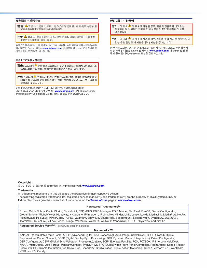
The following diagram shows ways the XTP T HDMI and XTP R HDMI can be integrated in an XTP matrix application.
FLEX I/O
SWITCHED 12VDC40W MAX TOTAL
LAN
1 2 3 4
COM1
TX RX RTS CTS
IR/SERIAL
1
S G S G
2
RELAY
3
S G S G+ - + -
+ - + -
4 1 21 2 3 4
3 4 5
S G S G
6 7
S G S G
8 5 6 7 8
COM2
TX RX
COM3
TX RX
COM7
TX RX
COM4
TX RX RTS CTS
COM5
TX RX
COM6
TX RX
COM8
TX RX
eBUS
+VPWR OUT = 12W
D -S +S
5A MAX
100-240V 50-60Hz
100-240V 1.3A, 50-60Hz
CLASS 2 WIRING
1 2
17TTAUDIO/VIDEOAPPARATUS
XPA 1002C US
LEVEL
11 2 1 2LIMITER/
PROTECT
SIGNAL
2
INPUTS OUTPUTREMOTE
0 0
10V 50 mAVOL/MUTE
STANDBY
LISTED
POWER12V
INPUTS
HDMI
--A MAX
RxTx
RS-232 IR
RxTx−+ −+
L R
LOOP-THRU
RESET
OVER XTPAUDIO
OFF XTP T HDMI
HDMI AUDIOON
LANACT LINK
SIG LINK
XTP OUT
POWER12V
INPUTS
HDMI
--A MAX
RxTx
RS-232 IR
RxTx−+ −+
L R
LOOP-THRU
RESET
OVER XTPAUDIO
OFF XTP T HDMI
HDMI AUDIOON
LANACT LINK
SIG LINK
XTP OUT
POWER12V
INPUTS
HDMI
--A MAX
RxTx
RS-232 IR
RxTx−+ −+
L R
LOOP-THRU
RESET
OVER XTPAUDIO
OFF XTP T HDMI
HDMI AUDIOON
LANACT LINK
SIG LINK
XTP OUT
POWER12V
OUTPUTS
HDMI
--A MAX
RxTx
RS-232 IR RL
RxTx -+ -+
1 2
OVER XTP AUDIO
OFF
HDMI AUDIOON
XTP R HDMIS/PDIF RELAYS
RESET
LANACT LINK
SIG LINK
XTP IN
Flat Panel Display
HDMI
RS-232
Ethernet
XTP R HDMI Long Distance XTP Receiver for HDMI
POWER12V
OUTPUTS
HDMI
--A MAX
RxTx
RS-232 IR RL
RxTx -+ -+
1 2
OVER XTP AUDIO
OFF
HDMI AUDIOON
XTP R HDMIS/PDIF RELAYS
RESET
LANACT LINK
SIG LINK
XTP IN
Flat Panel Display
HDMI
IR
Ethernet
XTP R HDMI Long Distance XTP Receiver for HDMI
STANDBY/ON
PQLS HDMI OPEN/CLOSE FL OFF
USB
INPUTS
OUTPUTS
OU
TX
TP
CP
4o
SA
AU
DIO
LR
LR
LR
LR
OUT
LAN
ACT
LINK
RESET
100-240V
50-60Hz
--A MAX
REMOTERS 232/RS422
DISCONNECT POWERCORD BEFORE
SERVICING
INX
TP
CP
4i V
GA
AU
DIO
LR
LR
LR
LR
IN
INX
TP
CP
4i V
GA
AU
DIO
LR
LR
LR
LR
IN
IN
IN
XT
P C
P 4
i
RS
-232
IR
Tx
Rx
Tx
Rx
RS
-232
IR
Tx
Rx
Tx
Rx
RS
-232
IR
Tx
Rx
Tx
Rx
RS
-232
IR
Tx
Rx
Tx
Rx
SIG
LI
NK
XTP
PW
R
AC
T
LIN
KLA
NX
TP
PW
R
AC
T
LIN
KLA
NX
TP
PW
R
AC
T
LIN
KLA
NX
TP
PW
R
AC
T
LIN
KLA
N
IR/R
S-2
32 O
VE
R X
TP
IN
IN
XT
P C
P 4
i
RS
-232
IR
Tx
Rx
Tx
Rx
RS
-232
IR
Tx
Rx
Tx
Rx
RS
-232
IR
Tx
Rx
Tx
Rx
RS
-232
IR
Tx
Rx
Tx
Rx
SIG
LI
NK
SIG
LI
NK
SIG
LI
NK
SIG
LI
NK
SIG
LI
NK
SIG
LI
NK
SIG
LI
NK
XTP
PW
R
AC
T
LIN
KLA
NX
TP
PW
R
AC
T
LIN
KLA
NX
TP
PW
R
AC
T
LIN
KLA
NX
TP
PW
R
AC
T
LIN
KLA
N
IR/R
S-2
32 O
VE
R X
TP
OU
T
OUT
XT
P C
P 4
o
RS
-232
IR
Tx
Rx
Tx
Rx
RS
-232
IR
Tx
Rx
Tx
Rx
RS
-232
IR
Tx
Rx
Tx
Rx
RS
-232
IR
Tx
Rx
Tx
Rx
SIG
LI
NK
XTP
PW
R
AC
T
LIN
KLA
NX
TP
PW
R
AC
T
LIN
KLA
NX
TP
PW
R
AC
T
LIN
KLA
NX
TP
PW
R
AC
T
LIN
KLA
N
IR/R
S-2
32 O
VE
R X
TP
OU
T
OUT
XT
P C
P 4
o
RS
-232
IR
Tx
Rx
Tx
Rx
RS
-232
IR
Tx
Rx
Tx
Rx
RS
-232
IR
Tx
Rx
Tx
Rx
RS
-232
IR
Tx
Rx
Tx
Rx
SIG
LI
NK
SIG
LI
NK
SIG
LI
NK
SIG
LI
NK
SIG
LI
NK
SIG
LI
NK
SIG
LI
NK
XTP
PW
R
AC
T
LIN
KLA
NX
TP
PW
R
AC
T
LIN
KLA
NX
TP
PW
R
AC
T
LIN
KLA
NX
TP
PW
R
AC
T
LIN
KLA
N
IR/R
S-2
32 O
VE
R X
TP
INX
TP
CP
4i D
VI P
roA
UD
IO
LR
LR
LR
LR
IN
INX
TP
CP
4i D
VI P
roA
UD
IO
LR
LR
LR
LR
IN
OU
TX
TP
CP
4o
DV
I Pro
AU
DIO
LR
LR
LR
LR
OUT
OU
TX
TP
CP
4o
DV
I Pro
AU
DIO
LR
LR
LR
LR
OUT
INX
TP
CP
4i H
DM
IA
UD
IO
LR
LR
LR
LR
IN
INX
TP
CP
4i H
DM
IA
UD
IO
LR
LR
LR
LR
IN
OU
TX
TP
CP
4o
HD
MI
AU
DIO
LR
LR
LR
LR
OUT
OU
TX
TP
CP
4o
HD
MI
AU
DIO
LR
LR
LR
LR
OUT
Laptop
PC
HDMI
Ethernet
Ethernet
Ethernet
Ethernet
Stereo Audio
IR
Shielded Twisted PairCable
RS-232 IR
Blu-ray
AV ControlNetwork
IPCP 505 IP Link Control Processor
XTP T HDMI Long Distance XTP Transmitter for HDMI
HDMI
Ethernet
XTP T HDMI Long Distance XTP Transmitter for HDMI
HDMI
Ethernet
XTP T HDMI Long Distance XTP Transmitter for HDMI
TLP 1000TV 10" Tabletop TouchLink Touchpanel
XPA 1002 Stereo Power Ampli�er SI 28
Surface Mount Speakers
XTP CrossPoint 3200 Modular Digital Matrix Switcher
House Network Switch
Ethernet
Figure 1. XTP T HDMI and XTP R HDMI Matrix Application Example
System CompatibilityThe XTP T HDMI and XTP R HDMI are compatible with XTP Systems, but the maximum video resolution may be limited with different XTP devices. See the table below for maximum video resolutions and refresh rates for various XTP Systems.
Output
Non-4K 4K Fiber 4K Plus
Inp
ut
Analog 1920x1200 @ 60 Hz 1920x1200 @ 60 Hz 1920x1200 @ 60 Hz
Non-4K Digital 2048x1080 @ 60 Hz 2048x1080 @ 60 Hz 2048x1080 @ 60 Hz
4K Fiber 2048x1080 @ 60 Hz 4096x2160 @ 24 Hz 4096x2160 @ 24 Hz
4K PLUS 2048x1080 @ 60 Hz 4096x2160 @ 24 Hz 4096x2160 @ 60 Hz
XTP T HDMI Transmitter and XTP R HDMI Receiver • Introduction 3
Features• Reliable cable infrastructure — Provides high reliability and maximum performance
on an economical and easily installed cable infrastructure.
• Support for computer-video to 1920x1200, including HDTV 1080p/60 Deep Color and 2K signals — Maintains superior image quality at the highest resolutions.
• Shielded twisted pair cable compatibility — Optimized for use with common shielded twisted pair cable types. XTP Systems fully support a maximum transmission distance of 330 feet (100 meters) for all compatible resolutions when used with shielded twisted pair cable. Shielded twisted pair cabling with solid center conductor sizes of 24 AWG or better is recommended for optimal performance.
• Bidirectional RS-232 and IR insertion — Allows a remote display to be controlled without the need for additional cabling through bidirectional RS-232 and IR control signals inserted into the XTP output.
• HDMI specification features — Support data rates up to 6.75 Gbps, Deep Color up to 12-bit, 3D, and HD lossless audio formats.
• HDCP compliance — Ensures display of content-protected media and interoperability with other HDCP-compliant devices.
• EDID Minder — Automatically manages EDID communication between connected devices. It ensures that all sources power up properly and reliably outputs content for display.
• Key Minder — Authenticates and maintains continuous HDCP encryption between input and output devices to ensure quick and reliable switching in professional AV environments, while enabling simultaneous distribution of a single source signal to one or more displays.
• Ethernet extension — Centralized 10/100 Ethernet communication can be implemented via an Ethernet pass-through port to reduce the amount of independent network drops required within a system.
• Remote power capability — Allows the devices to be powered by an XTP CrossPoint Matrix Switcher or XTP Power Injectors to simplify integration.
• Multiple embedded audio formats — Provides reliable operation with HDMI sources, compatible with a broad range of multi-channel audio signals.
• XTP compatibility — Provides a completely integrated solution for multiple digital and analog formats through XTP integrated system products. XTP is a flexible, reliable signal switching and distribution system.
• UL 2043 plenum rated — Meets UL 2043 for smoke and heat release for installation within a plenum airspace above a drop ceiling - power supply excluded. Above-the-ceiling placement conceals the device to prevent theft, and is convenient for installing equipment when space inside the room is limited.
• Transmitter HDMI loop-through with selectable audio control — Features an active HDMI output with support for embedded audio for connection to a local monitor.
• Transmitter selectable analog stereo audio input embedding — Supports balanced or unbalanced audio for extended transmission by embedding stereo audio into the signal stream. This feature enables direct connection of separate stereo audio signals from a laptop, Blu-ray Disc™ player, or other device.
• Receiver HDMI audio de-embedding with analog stereo and digital S/PDIF audio outputs — Digital HDMI audio is made available as a balanced or unbalanced analog stereo signal on captive screw connectors or a S/PDIF connector.
XTP T HDMI Transmitter and XTP R HDMI Receiver • Installation 4
Installation
This section contains the installation procedures for the XTP T HDMI and XTP R HDMI. Topics in this section include:
• Rear Panel Connectors
• Connection Details
Rear Panel Connectors
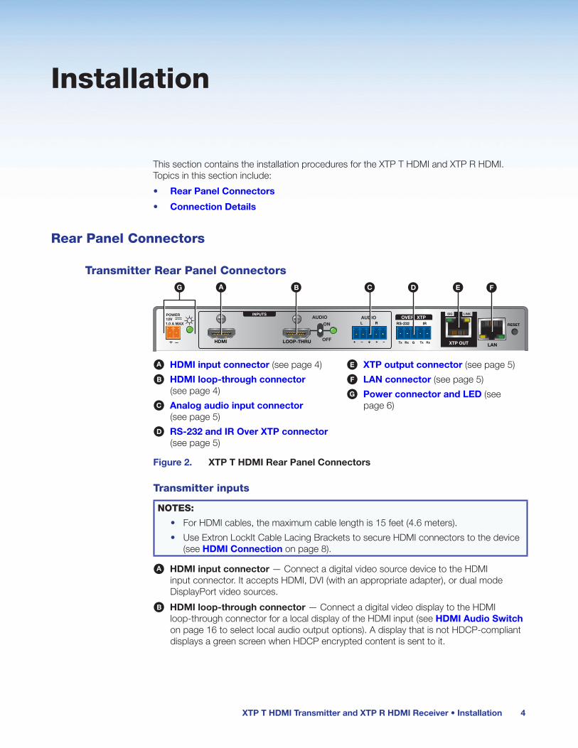
Transmitter Rear Panel Connectors
POWER12V
HDMI
1.0 A MAX
Rx GTx
RS-232 IR
RxTx−+ −+
L R
LOOP-THRU
RESET
AUDIO
OFF
ONAUDIO
SIG LINK
XTP OUT
INPUTSOVER XTP
LAN
A B C D E FG
A HDMI input connector (see page 4)
B HDMI loop-through connector (see page 4)
C Analog audio input connector (see page 5)
D RS-232 and IR Over XTP connector (see page 5)
E XTP output connector (see page 5)
F LAN connector (see page 5)
G Power connector and LED (see page 6)
Figure 2. XTP T HDMI Rear Panel Connectors
Transmitter inputs
NOTES:
• For HDMI cables, the maximum cable length is 15 feet (4.6 meters).
• Use Extron LockIt Cable Lacing Brackets to secure HDMI connectors to the device (see HDMI Connection on page 8).
A HDMI input connector — Connect a digital video source device to the HDMI input connector. It accepts HDMI, DVI (with an appropriate adapter), or dual mode DisplayPort video sources.
B HDMI loop-through connector — Connect a digital video display to the HDMI loop-through connector for a local display of the HDMI input (see HDMI Audio Switch on page 16 to select local audio output options). A display that is not HDCP-compliant displays a green screen when HDCP encrypted content is sent to it.

XTP T HDMI Transmitter and XTP R HDMI Receiver • Installation 5
C Analog audio input connector — Connect an audio source to the 5-pole captive screw connectors (see figure 2, C on the previous page). Wire the connector as shown in figure 3.
Unbalanced Audio InputBalanced Audio Input
TipRing
TipRing
Sleeves
TipSleeve
SleeveTip
LR
LR
Do not tin the wires!
Figure 3. Audio Input Wiring
Transmitter XTP interconnection
D RS-232 Over XTP port — To pass bidirectional serial signals between XTP-compatible devices, connect a control device to the 5-pole captive screw connector (see figure 2, D on the previous page). The port includes only the 3 poles labeled “RS-232.”
IR Over XTP port — To transmit and receive IR signals (up to 56 kHz), connect a control device to the 5-pole captive screw connector (see figure 2, D on the previous page). This port includes the 2 poles labeled “IR” and shares the ground pole with the RS-232 port.
NOTE: RS-232 and IR data can be transmitted simultaneously (see RS-232 and IR Communication on page 11 for wiring details).
E XTP output connector — Connect a twisted pair cable to this RJ-45 connector (see figure 2, E on the previous page) on the XTP T HDMI and the XTP input port on another XTP device to pass all signals (see TP Cable Termination and Recommendations on page 9). This cable carries the following signals:
• Digital video
• Digital audio
• Bidirectional RS-232 and IR commands
• Remote power
• Ethernet communication
• System communication
Signal LED indicator — Lights green when the transmitter outputs an XTP signal to a compatible receiver or matrix switcher.
Link LED indicator — Lights yellow when XTP devices are connected and communication is established.
ATTENTION:
• Do not connect this connector to a computer data or telecommunications network.
• Ne connectez pas ce connecteur à un réseau de données informatiques ou à un réseau de télécommunications.
• XTP remote power is intended for indoor use only. No part of the network that uses XTP remote power should be routed outdoors (see Remote power on page 14).
• XTP à distance est destiné à une utilisation en intérieur seulement. Aucune partie du réseau qui utilise l’alimentation XTP à distance ne peut être routée en extérieur (voir Remote power à la page 14).
F LAN connector — Connect a control device or device to be controlled to the pass-through LAN connector (see figure 2, F on the previous page) for 10/100Base-T Ethernet communication. LEDs on the connector indicate link and activity status.
IR
Tx Rx G Tx Rx
RS-232
IR
Tx Rx G Tx Rx
RS-232
Signal
Link

XTP T HDMI Transmitter and XTP R HDMI Receiver • Installation 6
Transmitter power
G Power connector and LED — Connect the external 12 V, 1.5 A power supply to the 2-pole captive screw connector (see figure 2, G on page 4). For wiring considerations, see Power Connection on page 12. The Power LED lights to indicate the device is receiving power.
NOTE: The XTP T HDMI can also be powered remotely (see Remote power on page 14).
Receiver Rear Panel Connectors
POWER12V 1.0 A MAX
Rx GTx
RS-232 IR RL
RxTx -+ -+
1 2AUDIO
ONAUDIO
RESET
OVER XTP OUTPUTS RELAYSSIG LINK
XTP IN HDMIOFF
S/PDIFLAN
A B C D E F GH
A XTP input connector (see page 6)
B LAN connector (see page 7)
C RS-232 and IR Over XTP connector (see page 7)
D HDMI output connector (see page 7)
E Analog audio output connector (see page 7)
F S/PDIF output connector (see page 7)
G Relay connector (see page 8)
H Power connector and LED (see page 8)
Figure 4. XTP R HDMI Rear Panel Connectors
Receiver XTP interconnection
A XTP Input connector — Connect a twisted pair cable to this RJ-45 connector on the XTP R HDMI and the XTP output port on another XTP device to pass all signals (see TP Cable Termination and Recommendations on page 9). This cable carries the following signals:
• Digital video
• Digital audio
• Bidirectional RS-232 and IR commands
• Remote power
• Ethernet communication
• System communication
Signal LED indicator — Lights green when the receiver is receiving an active XTP input signal.
Link LED indicator — Lights yellow when XTP devices are connected and communication is established.
ATTENTION:
• Do not connect this connector to a computer data or telecommunications network.
• Ne connectez pas ce connecteur à un réseau de données informatiques ou à un réseau de télécommunications.
• XTP remote power is intended for indoor use only. No part of the network that uses XTP remote power should be routed outdoors (see Remote power on page 14).
• XTP à distance est destiné à une utilisation en intérieur seulement. Aucune partie du réseau qui utilise l’alimentation XTP à distance ne peut être routée en extérieur (voir Remote power à la page 14).
Signal
Link

XTP T HDMI Transmitter and XTP R HDMI Receiver • Installation 7
B LAN connector — Connect a control device or device to be controlled to the receiver for 10/100 Ethernet communication through this pass-through port (see figure 4. B on the previous page). LEDs on the connector indicate link and activity status.
C RS-232 Over XTP port — To pass bidirectional serial signals between XTP-compatible devices, connect a control device to the 5-pole captive screw connector (see figure 4. C on the previous page). The port includes only the 3 poles labeled “RS-232.”
IR Over XTP port — To transmit and receive IR signals (up to 56 kHz), connect a control device to the 5-pole captive screw connector (see figure 4. C on the previous page). This port includes the 2 poles labeled “IR” and shares the ground pole with the RS-232 port.
NOTE: RS-232 and IR data can be transmitted simultaneously (see RS-232 and IR Communication on page 11 for wiring details).
Receiver outputs
D HDMI output connector — Connect a display device to the female HDMI connector (see figure 4, D on the previous page). It supports HDMI or DVI (with an appropriate adapter) signals.
NOTES:
• The maximum cable length is 15 feet (4.6 meters).
• Use an Extron LockIt Cable Lacing Bracket to secure the HDMI connector to the device (see HDMI Connection on the next page).
E Analog audio output connector — Connect a balanced or unbalanced, stereo or mono audio output device to the 3.5 mm, 5-pole captive screw connector (see figure 4, E on the previous page) for analog audio output. Wire the connector as shown in figure 5.
Do not tin the wires!
Balanced Audio Output
TipRing
TipRing
Sleeves
Unbalanced Audio Output
Tip
No Ground Here
No Ground Here
TipSleeves
LR
LR
Figure 5. Audio Output Wiring
ATTENTION:
• For unbalanced audio, connect the sleeves to the contact ground. Do not connect the sleeves to the negative (-) contacts.
• Pour l’audio asymétrique, connectez les manchons au contact au sol. Ne pas connecter les manchons aux contacts négatifs (–).
F S/PDIF output connector — Connect an audio device to the female orange RCA connector for digital S/PDIF audio output (see figure 4, F on the previous page). The type of audio present on this output is dictated by the following (see Audio Output Overview on page 17 for supported audio formats on the S/PDIF output):
• The audio format selected on the source material or device.
• The source device automatically outputting an audio format through EDID.
IR
Tx Rx G Tx Rx
RS-232
IR
Tx Rx G Tx Rx
RS-232

XTP T HDMI Transmitter and XTP R HDMI Receiver • Installation 8
Receiver relay
G Relay connector — Connect equipment that can be controlled via momentary or latching contact, like projector screens or lifts, to normally open relays (see figure 4, G on page 6).
ATTENTION:
• Do not exceed 24 V at 1.0 A for each port.
• Ne pas dépasser 24 volts à 1,0 A pour chaque port.
Receiver power
H Power connector and LED — Connect the external 12 V, 1.5 A power supply to the 2-pole captive screw connector (see figure 4, H on page 6). For wiring considerations, see Power Connection on page 12. The Power LED lights to indicate the device is receiving power.
NOTE: The XTP R HDMI can also be powered remotely (see Remote power on page 14).
Connection Details
HDMI ConnectionTo secure the HDMI cable to the HDMI input connector, use an Extron LockIt Cable Lacing Bracket and a tie wrap.
3
1
2
3
4
5
Figure 6. Installing the LockIt Cable Lacing Bracket
1. Plug the HDMI cable into the panel connection (see figure 6, 1).
2. Loosen the HDMI connection mounting screw from the panel (2) enough to allow the LockIt to be placed over it. The screw does not have to be removed.
3. Place the LockIt on the screw and against the HDMI connector (3), and then tighten the screw to secure the bracket.
4. Loosely place the included tie wrap around the HDMI connector and the LockIt (4).
5. While holding the connector securely against the cable lacing bracket, use pliers or similar tools to tighten the tie wrap, then remove any excess length (5).
ATTENTION:
• Connect and pull the tie wraps until they are secure. Do not overtighten.
• Connectez et tirez les serre-câbles jusqu’à ce qu’ils soient sécurisés. Ne pas trop serrer.

XTP T HDMI Transmitter and XTP R HDMI Receiver • Installation 9
TP Cable Termination and RecommendationsUse the following pin configurations for twisted pair cables.
12345678
RJ-45Connector
Insert TwistedPair Wires
Pins:
Pin
1
2
3
4
5
6
7
8
Wire color
White-green
Green
White-orange
Blue
White-blue
Orange
White-brown
Brown
Wire colorT568A T568B
White-orange
Orange
White-green
Blue
White-blue
Green
White-brown
Brown
TIA/EIA-T568B
Pin Wire Color
1 White-orange
2 Orange
3 White-green
4 Blue
5 White-blue
6 Green
7 White-brown
8 Brown
Figure 7. TP Cable Termination
Supported cables
The XTP T HDMI and XTP R HDMI are compatible with shielded twisted pair (F/UTP, SF/UTP, and S/FTP) cable.
ATTENTION:
• Do not use Extron UTP23SF-4 Enhanced Skew-Free AV UTP cable or STP201 cable to link the XTP products.
• N’utilisez pas le câble AV Skew-Free UTP version améliorée UTP23SF d’Extron ou le câble STP201 pour relier les produits XTP.
• To ensure FCC Class A and CE compliance, STP cables and STP connectors are required.
• Afin de s’assurer de la compatibilité entre FCC Classe A et CE, les câbles STP et les connecteurs STP sont nécessaires.

XTP T HDMI Transmitter and XTP R HDMI Receiver • Installation 10
Cable recommendations
Extron recommends using the following practices for XTP communication to achieve full transmission distances up to 330 feet (100 meters) and reduce transmission errors.
• Use the following Extron XTP DTP 24 SF/UTP cables and connectors for the best performance:
• XTP DTP 24/1000 Non-Plenum 1000’ (305 m) spool 22-236-03
• XTP DTP 24P/1000 Plenum 1000’ (305 m) spool 22-235-03
• XTP DTP 24 Plug Package of 10 101-005-02
• If not using XTP DTP 24 cable, at a minimum, Extron recommends 24 AWG, solid conductor, STP cable with a minimum bandwidth of 400 MHz.
• Terminate cables with shielded connectors to the TIA/EIA-T568B standard (see figure 7 on the previous page).
• Limit the use of more than two pass-through points, which may include patch points, punch down connectors, couplers, and power injectors. If these pass-through points are required, use shielded couplers and punch down connectors.
NOTE: When using STP cable in bundles or conduits, consider the following:
• Do not exceed 40% fill capacity in conduits.
• Do not comb the cable for the first 20 meters, where cables are straightened, aligned, and secured in tight bundles.
• Loosely place cables and limit the use of tie wraps or hook-and-loop fasteners.
• Separate twisted pair cables from AC power cables.

XTP T HDMI Transmitter and XTP R HDMI Receiver • Installation 11
RS-232 and IR CommunicationThe RS-232 and IR Over XTP connector is for pass-through transmission of serial signals, such as projector control signals, and infrared data. To pass bidirectional serial command signals between XTP-compatible devices, connect a control device to the three poles (Tx, Rx, and G) under “RS-232” of the 5-pole captive screw connector. To transmit and receive IR signals, connect a control device to the three poles (G, Tx, and Rx) under “IR.” The ground (G) pole is shared.
NOTE: RS-232 and IR data can be transmitted or received simultaneously (see figure 8 for wiring considerations).
Tx/RxPins
Rx
Tx
RS
-232
IR R
xT
x
TxRx
RxTx
IR Device
RS-232 Device
G
G
G
Figure 8. RS-232 and IR Over XTP Connector Wiring Configuration
ATTENTION: The length of the exposed wires in the stripping process is important.
ATTENTION : La longueur des câbles exposés est importante lorsque l’on entreprend de les dénuder.
• The ideal length is 3/16 inch (5 mm).
• La longueur idéale est de 5 mm (3/16 inches).
• Any longer and the exposed wires may touch, causing a short circuit between them.
• S’ils sont un peu plus longs, les câbles exposés pourraient se toucher et provoquer un court circuit.
• Any shorter and the wires can be easily pulled out even if tightly fastened by the captive screws.
• S’ils sont un peu plus courts, ils pourraient sortir, même s’ils sont attachés par les vis captives.

XTP T HDMI Transmitter and XTP R HDMI Receiver • Installation 12
Power ConnectionApply power to the transmitter or receiver locally with the provided power supply (if necessary, see figure 9 for wiring considerations) or remotely (through the XTP connector) with a power injector or an XTP CrossPoint matrix switcher.
Local power
SECTION A–A
AA
Power SupplyOutput Cord
2-Pole Captive ScrewConnector
RidgesSmooth
Tie Wrap
3/16”(5 mm) Max.
Figure 9. Power Wiring
Both the transmitter and receiver can be powered by a local power supply. See the notifications on the next page for local power considerations.

XTP T HDMI Transmitter and XTP R HDMI Receiver • Installation 13
WARNING: The DC output cables must be kept separate from each other while the power supply is plugged in. Remove power before wiring.
AVERTISSEMENT : Les câbles de sortie CC doivent être séparés les uns des autres tant que la source d’alimentation est branchée. Coupez l’alimentation avant d’effectuer les raccordements.
ATTENTION:
• This product is intended for use with a UL Listed power source marked “Class 2” or “LPS” rated 12 VDC, 1.0 A minimum, 48 VDC (PoE), minimum 0.35 A, or an Extron UL Listed XTP remote power source. Always use a power supply supplied by or specified by Extron. Use of an unauthorized power supply voids all regulatory compliance certification and may cause damage to the supply and the unit.
• Ce produit est destiné à une utilisation avec une source d’alimentation certifiée UL de classe 2 ou LPS et calibrée à 12 Vcc, 1,0 A minimum, 48 Vcc (PoE), 0,35 A minimum, ou une source d’alimentation délocalisée XTP Extron certifiée UL. Utilisez toujours une source d’alimentation fournie par Extron. L’utilisation d’une source d’alimentation non autorisée annule toute conformité réglementaire et peut endommager la source d’alimentation ainsi que l’unité.
• Unless otherwise stated, the AC/DC adapters are not suitable for use in air handling spaces or in wall cavities. The installation must always be in accordance with the applicable provisions of National Electrical Code ANSI/NFPA 70, article 725 and the Canadian Electrical Code part 1, section 16. The power supply shall not be permanently fixed to a building structure or similar structure.
• Sauf mention contraire, les adaptateurs AC/DC ne sont pas appropriés pour une utilisation dans les espaces d’aération ou dans les cavités murales. Cette installation doit toujours être en accord avec les mesures qui s’applique au National Electrical Code ANSI/NFPA 70, article 725, et au Canadian Electrical Code, partie 1, section 16. La source d’alimentation ne devra pas être fixée de façon permanente à une structure de bâtiment ou à une structure similaire.
• Power supply voltage polarity is critical. Incorrect voltage polarity can damage the power supply and the unit. The ridges on the side of the cord identify the power cord negative lead.
• La polarité de la source d’alimentation est primordiale. Une polarité incorrecte pourrait endommager la source d’alimentation et l’unité. Les stries sur le côté du cordon permettent de repérer le pôle négatif du cordon d’alimentation.
• The length of the exposed (stripped) copper wires is important. The ideal length is 3/16 inch (5 mm).
• La longueur des câbles exposés est primordiale lorsque l’on entreprend de les dénuder. La longueur idéale est de 5 mm (3/16 inch).
TIP: Do not tin the stripped power supply leads. Tinned wires are not as secure in the captive screw connectors and could be pulled out.

XTP T HDMI Transmitter and XTP R HDMI Receiver • Installation 14
Remote power
Either device can be powered remotely through an XTP Power Injector or through an XTP matrix switcher.
ATTENTION:
• XTP remote power is intended for indoor use only. No part of the network that uses XTP remote power should be routed outdoors.
• L’alimentation à distance XTP est destinée à un usage en intérieur uniquement. Aucune partie du réseau qui utilise l’alimentation XTP à distance ne peut être routée en extérieur.
Power injector
To power either device remotely with an XTP Power Injector, power one device locally (see Local power on page 12) and connect an XTP Power Injector to the XTP cable run along the XTP ports (see the XTP Power Injector User Guide at www.extron.com for more installation information).
POWER12V
HDMI
0.7A MAX
Rx GTx
RS-232 IR
RxTx−+ −+
L R
LOOP THRU
RESETAUDIO
OFF
ONAUDIO
XTP T HDMILAN
SIG LINK
XTP OUT
INPUTS OVER XTP
LAN
SIG LINK
XTP IN
POWER12V
HDMI
1A MAX
Rx GTx
RS-232 IR
RxTx −+ −+
L R 1 2
OVER XTPAUDIO
OFF
ON
S/PDIF
RESET
XTP R HDMIRELAYSOUTPUTS
AUDIO
XTPPWR
XTP PWR
100-240V 50/60 Hz0.4A MAX
Power
XTP R HDMI XTP Receiver
XTP PI 100 XTP PowerInjector
Shielded Twisted PairCable
REMOTEPOWER
12V Local PowerSupply
XTP T HDMIXTP Transmitter
Figure 10. Typical Pont-to-Point Application with Remote Power
NOTE: The power injector provides remote power up to 330 feet with a shielded twisted pair cable with 24 AWG wire.
XTP CrossPoint matrix switcher
XTP CrossPoint matrix switchers have a fixed amount of power available to provide remote power to connected XTP devices (see the XTP CrossPoint matrix switcher user guide at www.extron.com for more details). To manage available power from the XTP CrossPoint matrix switcher, use the XTP System Configuration Software with the XTP CrossPoint matrix switcher.

XTP T HDMI Transmitter and XTP R HDMI Receiver • Operation 15
Operation
After all transmitters, all receivers, and their connected devices are powered up, the system is fully operational. If any problems are encountered, verify that the cables are routed and connected properly. If problems persist, call the Extron S3 Sales & Technical Support Hotline. See the contact numbers on the last page of this guide for the nearest Extron office. Topics in this section include:
• Front Panel Features
• HDMI Audio Switch
• EDID
• Audio Output Overview
• Reset Mode
Front Panel Features
Transmitter Front Panel Features
XTP T HDMI
CONFIG
INPUT
AUDIO SIGNAL CLIPHDCP
SIGNAL
ANALOG AUDIO
HDMI AUDIO
A B C
Figure 11. XTP T HDMI Front Panel Features
A Power LED indicator — Lights when power is applied to the device from the power supply. There are two Power LED indicators, one on the front panel and one on the rear panel (see figure 2, G on page 4).
B Configuration port — Connect a host device to the female USB mini-B port to configure the connected transmitter or receiver or update firmware.
C Input LED indicators
• Signal LED indicator — Lights when an active video signal is detected from the source.
• HDMI Audio LED indicator — Lights when the HDMI audio input is selected.
• HDCP LED indicator — Lights when the input signal is encrypted.
• Analog Audio LED indicator — Lights when the analog audio input is selected.
• Audio Signal Clip LED indicator — Lights when the analog audio input signal remains above -3 dBFS. The LED remains lit for 200 milliseconds after the signal falls below -3 dBFS.
XTP T HDMI Transmitter and XTP R HDMI Receiver • Operation 16
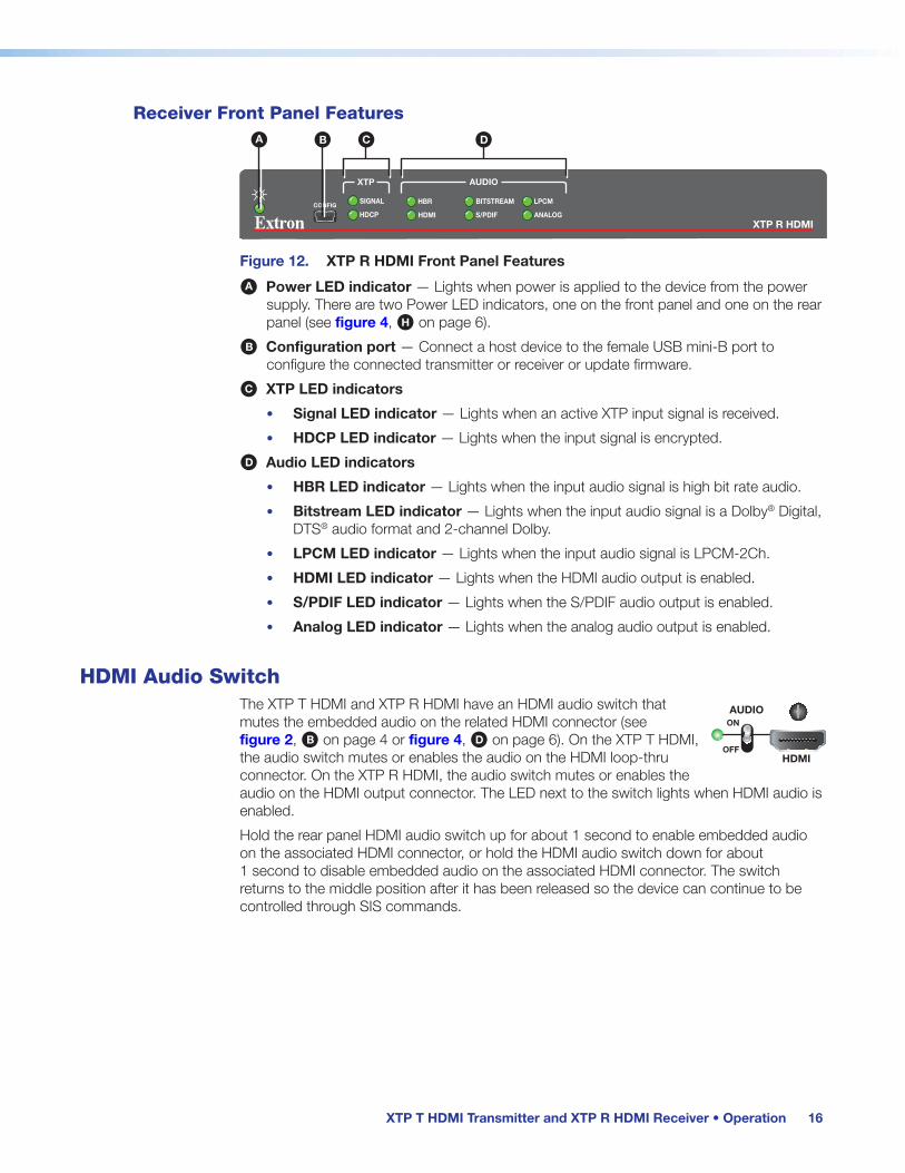
Receiver Front Panel Features
XTP R HDMI
CONFIG
XTP
HDCP
SIGNAL
AUDIO
HDMI
HBR
S/PDIF
BITSTREAM
ANALOG
LPCM
A B C D
Figure 12. XTP R HDMI Front Panel Features
A Power LED indicator — Lights when power is applied to the device from the power supply. There are two Power LED indicators, one on the front panel and one on the rear panel (see figure 4, H on page 6).
B Configuration port — Connect a host device to the female USB mini-B port to configure the connected transmitter or receiver or update firmware.
C XTP LED indicators
• Signal LED indicator — Lights when an active XTP input signal is received.
• HDCP LED indicator — Lights when the input signal is encrypted.
D Audio LED indicators
• HBR LED indicator — Lights when the input audio signal is high bit rate audio.
• Bitstream LED indicator — Lights when the input audio signal is a Dolby® Digital, DTS® audio format and 2-channel Dolby.
• LPCM LED indicator — Lights when the input audio signal is LPCM-2Ch.
• HDMI LED indicator — Lights when the HDMI audio output is enabled.
• S/PDIF LED indicator — Lights when the S/PDIF audio output is enabled.
• Analog LED indicator — Lights when the analog audio output is enabled.
HDMI Audio SwitchThe XTP T HDMI and XTP R HDMI have an HDMI audio switch that mutes the embedded audio on the related HDMI connector (see figure 2, B on page 4 or figure 4, D on page 6). On the XTP T HDMI, the audio switch mutes or enables the audio on the HDMI loop-thru connector. On the XTP R HDMI, the audio switch mutes or enables the audio on the HDMI output connector. The LED next to the switch lights when HDMI audio is enabled.
Hold the rear panel HDMI audio switch up for about 1 second to enable embedded audio on the associated HDMI connector, or hold the HDMI audio switch down for about 1 second to disable embedded audio on the associated HDMI connector. The switch returns to the middle position after it has been released so the device can continue to be controlled through SIS commands.
HDMI
AUDIOON
OFF

XTP T HDMI Transmitter and XTP R HDMI Receiver • Operation 17
EDIDTo manage EDID on the XTP T HDMI or XTP R HDMI, use the XTP System Configuration Software (see EDID Minder on page 34). The XTP T HDMI can record and save EDID in a user memory location, select a pre-defined EDID, or use EDID from a display connected to a receiver. EDID stored in the user memory location can come from the display connected to a receiver or a custom EDID imported through the XTP System Configuration Software.
NOTE: In matrix applications, EDID on the transmitter is assigned by the matrix switcher using the XTP System Configuration Software.
Audio Output OverviewBy default, the XTP T HDMI prioritizes embedded digital audio over analog audio. Use SIS commands (see SIS Configuration and Control on page 19) or the XTP System Configuration Software (see XTP System Configuration Software on page 26) to manually select the audio input. The following table shows the audio formats available on the receiver audio outputs.
Audio Format Availability on Receiver Audio Outputs
Audio Output
Audio Input Format HDMI S/PDIF Analog
2-channel LPCM up to 48 kHz Yes Yes Yes
Multi-channel PCM up to 7.1, 192 kHz Yes
Dolby Digital up to 5.1 Yes Yes
Dolby Digital EX Yes Yes
Dolby Digital Plus Yes
Dolby TrueHD Yes
DTS Digital Surround up to 5.1 Yes Yes
DTS-ES Matrix 6.1 Yes Yes
DTS-ES Discrete 6.1 Yes Yes
DTS-HD Yes
DTS-HD Master Audio Yes
NOTES:
• To pass analog audio without video to a display connected to the HDMI output connector on a connected receiver, the transmitter sends a black signal to simulate one of the following video signals:
• 720p @ 50 Hz
• 720p @ 60 Hz (default)
• 1080p @ 60 Hz
• To set the black signal, see the Black signal resolution SIS commands on page 21 or Transmitter device settings on page 32.

XTP T HDMI Transmitter and XTP R HDMI Receiver • Operation 18
Reset ModeUse the recessed Reset button on the rear panel of the transmitter or receiver (see figure 13, A) to restore factory-shipped firmware.
POWER12V 1.0 A MAX
Rx GTx
RS-232 IR RL
RxTx -+ -+
1 2AUDIO
ONAUDIO
RESET
OVER XTP OUTPUTS RELAYSSIG LINK
XTP IN HDMIOFF
S/PDIFLAN
POWER12V
HDMI
1.0 A MAX
Rx GTx
RS-232 IR
RxTx−+ −+
L R
LOOP-THRU
RESET
AUDIO
OFF
ONAUDIO
SIG LINK
XTP OUT
INPUTSOVER XTP
LAN
XTP T HDMI
XTP R HDMI
A
Figure 13. Rear Panel Reset Button
Reset Mode Summary
Mode Mode Activation Result Purpose and Notes
Factory Reset
1
Hold down the recessed Reset button while applying power to the device.
NOTE: After a mode 1 reset, update the device with the latest firmware version. DO NOT operate the firmware version that results from this mode reset.
The device reverts to the factory default firmware.
NOTE: If you do not want to update the firmware or perform a mode 1 reset by mistake, cycle power to the device to return to the firmware version running prior to the reset.
Use mode 1 to return to factory firmware for a single power cycle if an incompatibility issue arises.

XTP T HDMI Transmitter and XTP R HDMI Receiver • SIS Configuration and Control 19
SIS Configuration and Control
The XTP T HDMI and XTP R HDMI can be configured and controlled using SIS commands or the XTP System Configuration Software (see XTP System Configuration Software on page 26). This section contains SIS communication details and SIS commands and responses when connected directly to an XTP T HDMI or XTP R HDMI. Topics in this section include:
• Host Device Connection
• SIS Overview
• Command and Response Table for Transmitter SIS Commands
• Command and Response Table for Receiver SIS Commands
Host Device ConnectionUse a connected computer running the Extron DataViewer utility to send and receive SIS commands and responses. To connect directly to an XTP T HDMI or XTP R HDMI, connect the computer to the front panel USB configuration port (see figure 11, B on page 15 or figure 12, B on page 16).
SIS Overview
Host-to-Device and Device-to-Host CommunicationSIS commands consist of one or more characters per field. No special characters are required to begin or end a command sequence. When the XTP T HDMI or XTP R HDMI determines that a command is valid, it executes the command and sends a response to the host device. All responses from the transmitter or receiver to the host device end with a carriage return and a line feed (CR/LF = ]), which signals the end of the response character string. A string is one or more characters.
Error ResponsesWhen the XTP T HDMI or XTP R HDMI receives an SIS command and determines that it is valid, it performs the command and sends the corresponding response to the host device. If the command is determined invalid or contains invalid parameters, the transmitter or receiver returns an error response to the host. The error response codes are:
E01 = Invalid input number E14 = Not valid for this configuration
E10 = Invalid command E17 = Invalid command for signal type
E12 = Invalid port number E22 = Busy
E13 = Invalid parameter

XTP T HDMI Transmitter and XTP R HDMI Receiver • SIS Configuration and Control 20
Using the Command and Response Tables for SIS CommandsThe command and response tables beginning on the next page list the commands that the transmitter recognizes as valid, the responses that are returned to the host, and a description of the command function or the results of executing the command. Commands can be entered back-to-back in a string with no spaces. Figure 14 shows the hexadecimal equivalent of ASCII characters used in the command and response tables.
NOTE: Upper and lowercase text can be used interchangeably unless otherwise stated.
ASCII to Hex Conversion Table
•
Space
Figure 14. ASCII to Hexadecimal Conversion
Symbol Definitions
] = Carriage return and line feed
} = Carriage return with no line feed
| = Pipe (can be used interchangeably with the } character).
• = Space
E = Escape key
W = Can be used interchangeably with the E character.

XTP T HDMI Transmitter and XTP R HDMI Receiver • SIS Configuration and Control 21
Command and Response Tables for the Transmitter SIS CommandsThe following commands are for direct connection to the XTP T HDMI (see the XTP matrix switcher user guide for commands sent from the matrix switcher to the transmitter).
Command ASCII Command (Host to Device)
Response (Device to Host)
Additional Description
Audio Configuration CommandsInput audio format selection
Set input audio format EIX!AFMT} AfmtIX!] Set which audio input signal the transmitter sends. Auto prioritizes digital audio over analog audio.
View input audio format EIAFMT} AfmtIX!] View the input audio format setting.
Audio gain and attenuation
NOTE: Gain and attenuation commands are case-sensitive.
Set audio gain X@G AudX$] Set the audio gain.
Set audio attenuation X#g AudX$] Set the audio attenuation.
Increment audio level +G or +g AudX$] Increase the audio level by 1 dB.
Decrement audio level -G or -g AudX$] Decrease the audio level by 1 dB.
View audio level G AudX$] View the current audio level.
Loop-through audio mute
Mute loop-through audio 2*1Z Amt2*1] Mute the loop-through audio.
Unmute loop-through audio 2*0Z Amt2*0] Unmute the loop-through audio.
View loop-through audio mute status
2Z Amt2*X%] View the mute status of the loop-through audio.
Black video signal resolution
Set black video signal resolution
EAX^AFMT} AfmtAX^] Set the black video signal resolution.
View black video signal resolution
EAAFMT} AfmtAX^] View the current black video signal resolution.
KEY: X! = Input audio format 0 = auto (default)
1 = digital embedded 2 = analog
X@ = Audio gain 0 to 24 in 1 dB increments (0 = default)
X# = Audio attenuation -18 to 0 in 1 dB increments (0 = default)
X$ = Audio level -18 to +24 in 1 dB increments (0 = default)
X% = Audio mute 0 = unmute (default) 1 = mute loop-through audio
X^ = Black video signal resolution 2 = 720p @ 50 Hz 4 = 720p @ 60 Hz (default) 6 = 1080p @ 60 Hz

XTP T HDMI Transmitter and XTP R HDMI Receiver • SIS Configuration and Control 22
Command ASCII Command (Host to Device)
Response (Device to Host)
Additional Description
Black video signal for audio only
NOTE: The transmitter uses a black signal to simulate a 720p (50 Hz or 60 Hz) or 1080p (60 Hz) signal to pass audio without video.
Enable black video signal EB1AFMT} AfmtB1] Enable the black video signal for audio only.
Disable black video signal EB0AFMT} AfmtB0] Disable the black video signal.
View black video signal status EBAFMT} AfmtBX&] View the current black video signal status.
EDID Commands
NOTE: For EDID management, use the XTP System Configuration Software (see EDID Minder on page 34).
Advanced Configuration CommandsHDCP authorized device
HDCP authorized device on EE1HDCP} HdcpE1] Set the transmitter as an HDCP authorized device.
HDCP authorized device off EE0HDCP} HdcpE0] Set the transmitter as not an HDCP authorized device.
View HDCP authorized device status
EEHDCP} HdcpEX(] View the HDCP authorized device status.
Video mute
Mute video to black 2*1b Vmt2*1] Mute the video to black.
Unmute video 2*0b Vmt2*0] Unmute the video.
View video mute status 2b Vmt2*X1)] View current video mute status.
Test pattern
Set test pattern X1!J TstX1!] Set color bars test pattern resolution and refresh rate.
View test pattern setting J TstX1!] View the current test pattern setting.
KEY: X& = Enable or disable 0 = off or disabled
1 = on or enabled (default)
X( = HDCP authorized device status 0 = off 1 = on (default)
X1) = Video mute 0 = unmute (default) 1 = mute video to black
X1! = Test pattern 0 = disabled (default) 1 = 720p @ 50 Hz 3 = 720p @ 60 Hz 5 = 1080p @ 60 Hz

XTP T HDMI Transmitter and XTP R HDMI Receiver • SIS Configuration and Control 23
Command ASCII Command (Host to Device)
Response (Device to Host)
Additional Description
Reset mode
Reset to factory defaults EZXXX} Zpx] Reset all user settings back to factory defaults.
Status
View input signal presence 0LS FrqX1#] View the status of the input signal presence.
View HDCP input status EIHDCP} HdcpIX1$] View the HDCP status of the input.
View HDCP output status EO2HDCP} HdcpO2*X1$] View the HDCP status of the output.
View firmware version Q X.XX] View the current firmware version.
View full firmware version *Q X.XX.XXXX] View the current full firmware version.
View part number N XX-XXXX-XX] View the transmitter part number.
KEY: X1@ = Device name Text label, maximum seven alphanumeric characters
X1# = Video signal status 0 = video or TMDS signal not detected 1 = video or TMDS signal detected
X1$ = HDCP status 0 = no source 1 = HDCP-compliant source connected 2 = non-compliant source

XTP T HDMI Transmitter and XTP R HDMI Receiver • SIS Configuration and Control 24
Command and Response Tables for the Receiver SIS CommandsThe following commands are for direct connection to the XTP R HDMI (see the XTP matrix switcher user guide for commands sent from the matrix switcher to the receiver).
Command ASCII Command (Host to Device)
Response (Device to Host)
Additional Description
Audio Configuration CommandsVolume control
Set output volume level X1%V VolX1%] Set the output volume to X1%.
Increment output volume level +V VolX1%] Increase the output volume level by 1 dB.
Decrement output volume level -V VolX1%] Decrease the output volume level by 1 dB.
View output volume level V VolX1%] View the current output volume level.
KEY:
X1% = Volume 0 to 64 in 1 dB steps (64 = default)
X1% dB of Attenuation
Output Volume
X1% dB of Attenuation
Output Volume
X1% dB of Attenuation
Output Volume
0 76 0% 22 42 37.0% 44 20 70.0%
1 63 5.5% 23 41 38.5% 45 19 71.5%
2 62 7.0% 24 40 40.0% 46 18 73.0%
3 61 8.5% 25 39 41.5% 47 17 74.5%
4 60 10.0% 26 38 43.0% 48 16 76.0%
5 59 11.5% 27 37 44.5% 49 15 77.5%
6 58 13.0% 28 36 46.0% 50 14 79.0%
7 57 14.5% 29 35 47.5% 51 13 80.5%
8 56 16.0% 30 34 49.0% 52 12 82.0%
9 55 17.5% 31 33 50.5% 53 11 83.5%
10 54 19.0% 32 32 52.0% 54 10 85.0%
11 53 20.5% 33 31 53.5% 55 9 86.5%
12 52 22.0% 34 30 55.0% 56 8 88.0%
13 51 23.5% 35 29 56.5% 57 7 89.5%
14 50 25.0% 36 28 58.0% 58 6 91.0%
15 49 26.5% 37 27 59.5% 59 5 92.5%
16 48 28.0% 38 26 61.0% 60 4 94.0%
17 47 29.5% 39 25 62.5% 61 3 95.5%
18 46 31.0% 40 24 64.0% 62 2 97.0%
19 45 32.5% 41 23 65.5% 63 1 98.5%
20 44 34.0% 42 22 67.0% 64 0 100.0%
21 43 35.5% 43 21 68.5%

XTP T HDMI Transmitter and XTP R HDMI Receiver • SIS Configuration and Control 25
Command ASCII Command (Host to Device)
Response (Device to Host)
Additional Description
Audio mute
Mute all 3Z Amt3] Mute the audio.
Unmute all 0Z Amt0] Unmute the audio.
View audio mute status Z AmtX1^] View the audio mute status.
Advanced Configuration CommandsRelay control
Pulse relay X1&*3*X1*O RlyX1&*X*] Pulse relay X1& for X1* ms.
Toggle relay X1&*2O RlyX1&*X*] Toggle relay X1&.
Turn relay on X1&*1O RlyX1&*1] Turn relay X1& on.
Turn relay off X1&*0O RlyX1&*0] Turn relay X1& off.
View relay status X1&O RlyX1&*X*] View the on or off status of relay X1&.
Video mute
Mute video to black 1B Vmt1] Mute the video. The display shows a black screen.
Unmute video 0B Vmt0] Unmute the video.
View video mute status B VmtX1(] View the video mute status.
Reset mode
Reset to factory defaults EZXXX} Zpx] Reset all user settings back to factory defaults.
Status
View input signal presence 0LS FrqX2)] View the video or TMDS signal status.
View HDCP output status EOHDCP} HdcpOX2!] View the HDCP status of the output.
View firmware version Q X.XX] View the current firmware version.
View full firmware version *Q X.XX.XXXX] View the current full firmware version.
View part number N XX-XXXX-XX] View the receiver part number.
KEY: X* = Enable or disable 0 = disable
1 = enable
X1^ = Audio mute 0 = unmute all (default) 3 = mute all
X1& = Relay number 1 = relay 1 2 = relay 2
X1* = Pulse time 1-65535 (values are in 16 ms increments)X1( = Video mute 0 = unmute
1 = mute video to black
X2) = Video signal status 0 = video or TMDS signal not detected 1 = video or TMDS signal detected
X2! = HDCP status 0, 2, 4, 6 = no sink device detected 1, 3, 5 = sink detected with no HDCP encryption 7 = sink detected with HDCP encryption
XTP T HDMI Transmitter and XTP R HDMI Receiver • XTP System Configuration Software 26
XTP System Configuration Software
This section contains installation and configuration procedures for the XTP System Configuration Software to configure and control the XTP T HDMI and XTP R HDMI. Topics in this section include:
• Software Installation
• Software Operation
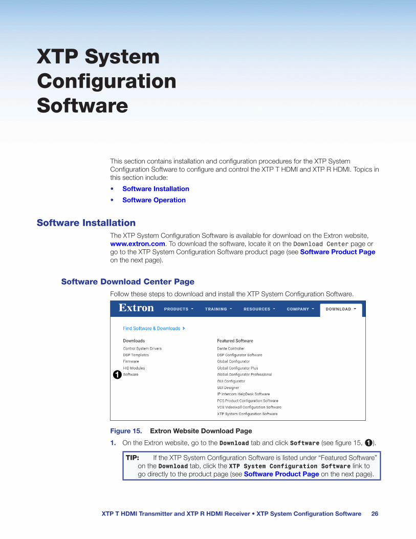
Software InstallationThe XTP System Configuration Software is available for download on the Extron website, www.extron.com. To download the software, locate it on the Download Center page or go to the XTP System Configuration Software product page (see Software Product Page on the next page).
Software Download Center PageFollow these steps to download and install the XTP System Configuration Software.
Figure 15. Extron Website Download Page
1. On the Extron website, go to the Download tab and click Software (see figure 15, 1).
TIP: If the XTP System Configuration Software is listed under “Featured Software” on the Download tab, click the XTP System Configuration Software link to go directly to the product page (see Software Product Page on the next page).

XTP T HDMI Transmitter and XTP R HDMI Receiver • XTP System Configuration Software 27
Figure 16. XTP System Configuration Software Download Link
2. Click the X link (see figure 16, 1).
3. Locate the XTP System Configuration Software and click the Download link (see figure 16, 2) to the right of the product name.
4. Submit required information to start the download. Note where the file is saved.
5. Open the executable (.exe) file from the save location.
6. Follow the instructions that appear on the screen to install the program.
Software Product PageThe software product page contains information about the software.
Figure 17. XTP System Configuration Software Product Page
To download and install the XTP System Configuration Software from this page:
1. In the Search field (see figure 17, 1) enter XTP System Configuration Software.
2. Press <Enter> on the keyboard or select XTP System Configuration Software from the drop-down menu.
3. Click the Download button (see figure 17, 2).
4. Submit any required information to start the download. Note where the file is saved.
5. Open the saved executable (.exe) file.
6. Follow the instructions that appear on the screen to install the program.

XTP T HDMI Transmitter and XTP R HDMI Receiver • XTP System Configuration Software 28
Software OperationThe XTP T HDMI and XTP R HDMI can be controlled directly from the front panel configuration port (see figure 11, B on page 15 or figure 12, B on page 16) or remotely from an XTP matrix switcher (see the XTP matrix switcher user guide for connection details from an XTP matrix switcher).
ConnectionThe XTP System Configuration Software opens to the Connections screen. This screen is used to establish communication with an XTP device through USB connection. Ensure the device is connected and powered on before proceeding.
Figure 18. Connections Screen (XTP T HDMI Detected)
To connect to a device:
1. Open the XTP System Configuration Software.
2. From the Connections screen, select the USB radio button (see figure 18, 1).
3. From the displayed list, select the connected device to be controlled (2).
4. Click the Connect button (3). The Device Settings screen opens (see Transmitter Configuration on page 32 or Receiver Configuration on page 36).
XTP T HDMI Transmitter and XTP R HDMI Receiver • XTP System Configuration Software 29
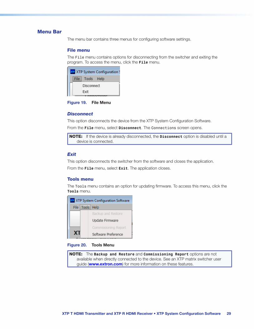
Menu BarThe menu bar contains three menus for configuring software settings.
File menu
The File menu contains options for disconnecting from the switcher and exiting the program. To access the menu, click the File menu.
Figure 19. File Menu
Disconnect
This option disconnects the device from the XTP System Configuration Software.
From the File menu, select Disconnect. The Connections screen opens.
NOTE: If the device is already disconnected, the Disconnect option is disabled until a device is connected.
Exit
This option disconnects the switcher from the software and closes the application.
From the File menu, select Exit. The application closes.
Tools menu
The Tools menu contains an option for updating firmware. To access this menu, click the Tools menu.
Figure 20. Tools Menu
NOTE: The Backup and Restore and Commissioning Report options are not available when directly connected to the device. See an XTP matrix switcher user guide (www.extron.com) for more information on these features.

XTP T HDMI Transmitter and XTP R HDMI Receiver • XTP System Configuration Software 30
Update Firmware
This option uploads firmware from the host device to the connected device.
1. From the Tools menu, select Update Firmware. A dialog box opens to ask permission to disconnect from the device.
Figure 21. Confirm Disconnect Dialog Box
2. Click the Yes button to disconnect from the device and continue with the firmware update process. The Update Firmware dialog box opens.
Figure 22. Update Firmware Dialog Box
3. Click the Select file from computer icon to select a firmware file from the connected host device. The Browse dialog box opens.
4. Select the desired firmware file and click the Open button.
5. Click the Close button after the firmware finishes updating.
Software Preference
This option resets all disabled confirmation dialogs to the default settings.
1. From the Tools menu, select Software Preference. The Software Preference dialog box opens.
Figure 23. Software Preference Dialog Box
2. Click the Reset button. The dialog box closes.

XTP T HDMI Transmitter and XTP R HDMI Receiver • XTP System Configuration Software 31
Help menu
The Help menu provides access to XTP System Configuration Software information, a link to the help file, and a link to the Extron website.
Figure 24. Help Menu
NOTE: The Tutorial (System Configuration) option is not available when directly connected to the device.
About the Software
This option provides basic information about the XTP System Configuration Software, including version number and copyright information.
Figure 25. About Dialog Box
1. From the Help menu, select About the Software. The About dialog box opens.
2. Click the Details button for more information.
3. Click the Ok button to close the dialog box.
Help
This option opens the XTP System Configuration Software help file in a Web browser.
From the Help menu, select Help.
Extron Website
This option opens the Extron website in a Web browser.
From the Help menu, select Extron Website.

XTP T HDMI Transmitter and XTP R HDMI Receiver • XTP System Configuration Software 32
Transmitter ConfigurationThe Device Settings screen allows a user to view and edit various device settings of the transmitter connected to the host device.
Transmitter device settings
When connected directly to an XTP T HDMI, the Device Settings screen contains configuration options for the transmitter only. Click the Device Settings icon (see figure 26, 1) on the Global Navigation Bar to open the Device Settings screen.
Figure 26. Transmitter Device Settings Screen
Status panel
2 Settings — Displays the device name and current EDID settings.
Video panel
3 Video input — Select the HDCP Authorized check box to set the transmitter as an HDCP authorized device or deselect it to indicate that the device is not an HDCP authorized device. By default, the check box is selected.
4 Video output — Select the Color Bars Test Pattern check box to transmit a test pattern to an XTP receiver or deselect it to stop transmitting a test pattern to an XTP receiver. If selected, also select a signal type from the Signal Type drop-down menu.
Audio panel
5 Audio format — Select one of the following radio buttons to determine the audio input format:
• Auto Detect — Automatically detects the input audio format. When enabled, HDMI audio has priority over analog audio.
• HDMI — Transmits embedded audio from an HDMI signal.
• Analog — Transmits an analog audio signal.
6 Analog audio — If applicable, move the handle of the Analog Audio Gain fader up or down or specify the desired gain in the field below the slider to adjust the audio gain or attenuation in dB.

XTP T HDMI Transmitter and XTP R HDMI Receiver • XTP System Configuration Software 33
7 Audio output (see figure 26 on the previous page) — Select the Enable Audio Only check box to enable a black signal for audio-only transmission to the HDMI output connector on a connected receiver. By default, the check box is selected.
If selected, also select the black signal resolution from the Signal Type drop-down menu. The default resolution is 720p @ 60 Hz.
Factory reset
8 Factory Reset (see figure 26) — Click the Factory Reset button to reset the transmitter to factory settings except for firmware.
NOTE: This is the same as the EZXXX SIS command (see Reset mode on page 23).
Device Information panel
The Device Information panel on the right side of the software screen displays device information and settings.
1 Model — Displays the device model.
2 Firmware Version — Displays the full firmware version.
3 Signal Present — Indicates whether an active signal is on the input.
4 HDCP — Displays the HDCP status of an active input.
5 EDID — Displays the current EDID assigned with EDID Minder (see EDID Minder on the next page.
6 Selected Audio Input — Displays the audio format of the selected input.
7 Audio Only — Displays whether the black video signal for audio-only transmission is enabled.
8 Analog Audio Gain — Displays the gain for analog audio.
XTP T HDMI Transmitter and XTP R HDMI Receiver • XTP System Configuration Software 34
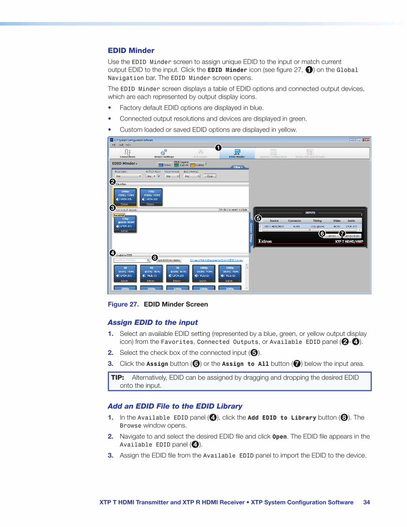
EDID Minder
Use the EDID Minder screen to assign unique EDID to the input or match current output EDID to the input. Click the EDID Minder icon (see figure 27, 1) on the Global Navigation bar. The EDID Minder screen opens.
The EDID Minder screen displays a table of EDID options and connected output devices, which are each represented by output display icons.
• Factory default EDID options are displayed in blue.
• Connected output resolutions and devices are displayed in green.
• Custom loaded or saved EDID options are displayed in yellow.
Figure 27. EDID Minder Screen
Assign EDID to the input
1. Select an available EDID setting (represented by a blue, green, or yellow output display icon) from the Favorites, Connected Outputs, or Available EDID panel (2-4).
2. Select the check box of the connected input (5).
3. Click the Assign button (6) or the Assign to All button (7) below the input area.
TIP: Alternatively, EDID can be assigned by dragging and dropping the desired EDID onto the input.
Add an EDID File to the EDID Library
1. In the Available EDID panel (4), click the Add EDID to Library button (8). The Browse window opens.
2. Navigate to and select the desired EDID file and click Open. The EDID file appears in the Available EDID panel (4).
3. Assign the EDID file from the Available EDID panel to import the EDID to the device.

XTP T HDMI Transmitter and XTP R HDMI Receiver • XTP System Configuration Software 35
Save output EDID
1. Right-click on the desired EDID icon in the Connected Outputs panel (see figure 27, 3 on the previous page).
2. Navigate to and select the Save EDID to Library option. The EDID setting is saved to the connected PC. Alternatively, right-click on the desired EDID, select Copy, and then Paste the EDID into the Favorites (see figure 27, 2) or Available EDID panel (see figure 27, 4).
Set favorite EDID
To add commonly used EDID settings to the Favorites panel (see figure 27, 2) for quick access, perform one of the following methods:
• Click and drag the desired EDID from the Connected Outputs (see figure 27, 3) or the Available EDID panel (see figure 27, 4) to the Favorites panel. The EDID setting is copied to the Favorites panel.
• Right-click the desired EDID and select Copy. Then, Paste the EDID setting into the Favorites panel.
EDID filters
The filters (see figure 28) can be used to easily locate a specific EDID setting.
1 Resolution filter
2 Refresh Rate filter
3 Video Format filter
4 Audio Format filter
5 Clear button
Figure 28. EDID Minder Filters
To use a filter or combination of filters, perform the following:
1. Select an EDID setting from one of the drop-down lists of the associated filter (see figure 28, 1-4). The available EDID options that match the filter selection are displayed in their respective panels.
2. Repeat step 1 to apply more filters.
NOTE: To clear the currently applied filters, click the Clear button next to the filters (see figure 28, 5). All filters are reset.
Common timings
This function automatically displays available EDID settings that are common among multiple selected outputs.
1. Hold <Ctrl> and click the desired outputs in the Connected Outputs panel (see figure 27, 3 on the previous page). The Common Timings tab (located to the right of the Connected Outputs panel) appears, listing the EDID settings common among the selected outputs.
2. Select the desired common EDID. The EDID is shown in the Available EDID panel (see figure 27, 4 on the previous page).
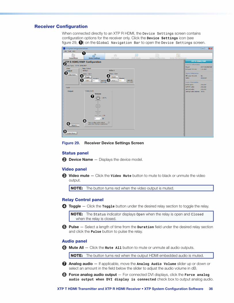
XTP T HDMI Transmitter and XTP R HDMI Receiver • XTP System Configuration Software 36
Receiver ConfigurationWhen connected directly to an XTP R HDMI, the Device Settings screen contains configuration options for the receiver only. Click the Device Settings icon (see figure 29, 1) on the Global Navigation Bar to open the Device Settings screen.
Figure 29. Receiver Device Settings Screen
Status panel
2 Device Name — Displays the device model.
Video panel
3 Video mute — Click the Video Mute button to mute to black or unmute the video output.
NOTE: The button turns red when the video output is muted.
Relay Control panel
4 Toggle — Click the Toggle button under the desired relay section to toggle the relay.
NOTE: The Status indicator displays Open when the relay is open and Closed when the relay is closed.
5 Pulse — Select a length of time from the Duration field under the desired relay section and click the Pulse button to pulse the relay.
Audio panel
6 Mute All — Click the Mute All button to mute or unmute all audio outputs.
NOTE: The button turns red when the output HDMI embedded audio is muted.
7 Analog audio — If applicable, move the Analog Audio Volume slider up or down or select an amount in the field below the slider to adjust the audio volume in dB.
8 Force analog audio output — For connected DVI displays, click the Force analog audio output when DVI display is connected check box to output analog audio.
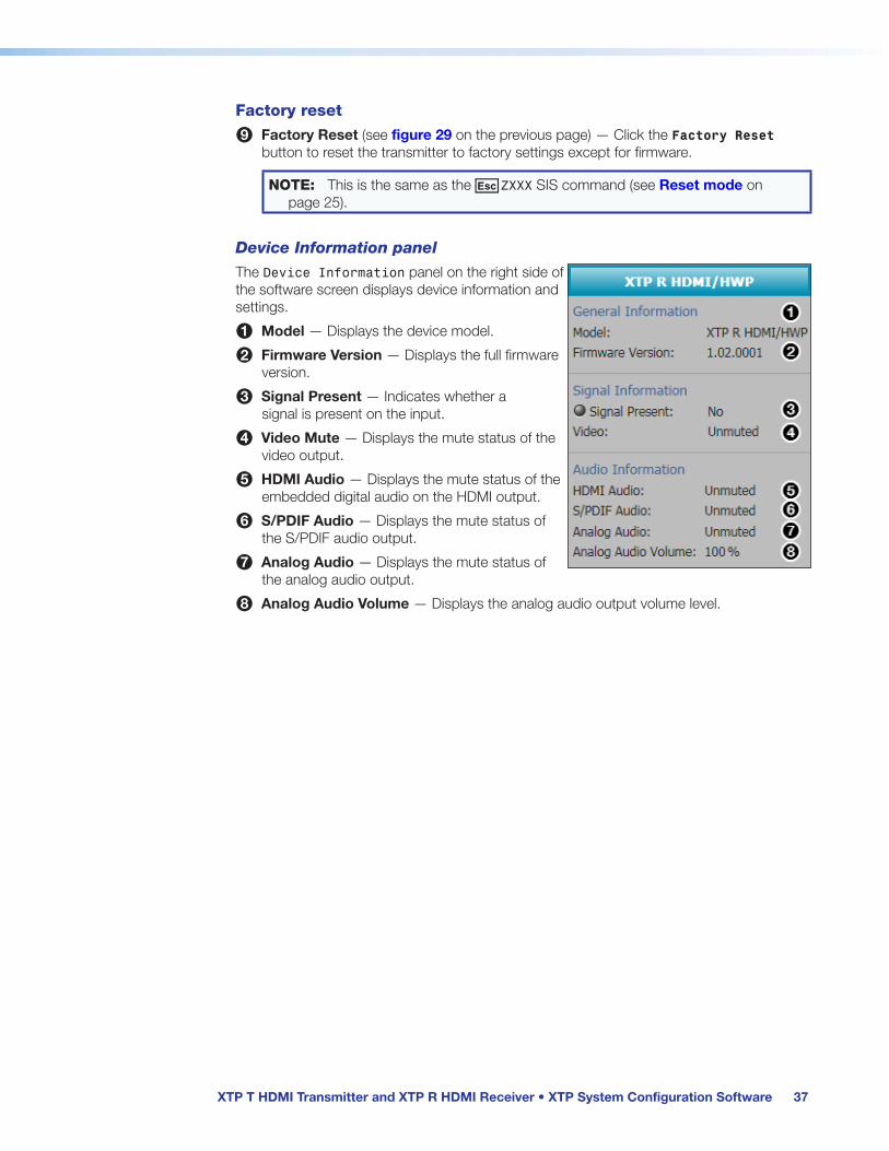
XTP T HDMI Transmitter and XTP R HDMI Receiver • XTP System Configuration Software 37
Factory reset
9 Factory Reset (see figure 29 on the previous page) — Click the Factory Reset button to reset the transmitter to factory settings except for firmware.
NOTE: This is the same as the EZXXX SIS command (see Reset mode on page 25).
Device Information panel
The Device Information panel on the right side of the software screen displays device information and settings.
1 Model — Displays the device model.
2 Firmware Version — Displays the full firmware version.
3 Signal Present — Indicates whether a signal is present on the input.
4 Video Mute — Displays the mute status of the video output.
5 HDMI Audio — Displays the mute status of the embedded digital audio on the HDMI output.
6 S/PDIF Audio — Displays the mute status of the S/PDIF audio output.
7 Analog Audio — Displays the mute status of the analog audio output.
8 Analog Audio Volume — Displays the analog audio output volume level.

XTP T HDMI Transmitter and XTP R HDMI Receiver • Reference Information 38
Reference Information
This section contains mounting information.
MountingThe XTP T HDMI and XTP R HDMI can be placed on a tabletop or mounted in a rack or underneath a desk.
Tabletop MountingAttach the provided rubber feet to the bottom four corners of the enclosure.
Furniture MountingGo to www.extron.com for a list of available furniture mounting kits. To install either device to furniture, follow the mounting kit instructions.
Rack MountingGo to www.extron.com for a list of compatible rack mounting kits. To install either device in a rack, follow the mounting kit instructions and see the UL guidelines for rack-mounted devices below.
UL guidelines for rack-mounted devices
The following Underwriters Laboratories (UL) guidelines pertain to the safe installation of the XTP T HDMI and XTP R HDMI in a rack.
1. Elevated operating ambient temperature — If installed in a closed or multi-unit rack assembly, the operating ambient temperature of the rack environment may be greater than room ambient temperature, Therefore, install the XTP T HDMI and XTP R HDMI in an environment compatible with the maximum ambient temperature (Tma = +122 ˚F, +50 ˚C) specified by Extron.
2. Reduced air flow — Install the equipment in a rack so that the amount of air flow required for safe operation of the equipment is no compromised.
3. Mechanical loading — Mount the equipment in the rack so that a hazardous condition is not achieved due to uneven mechanical loading.
4. Circuit overloading — Connect the equipment to the supply circuit and consider the effect that circuit overloading might have an overcurrent protection and supply wiring. Appropriate consideration of equipment nameplate ratings should be used when addressing this concern.
5. Reliable earthing (grounding) — Maintain reliable grounding of rack-mounted equipment. Pay particular attention to supply connections other than direct connections to the branch circuit (for example, the use of power strips).
Extron Warranty
Extron Electronics warrants this product against defects in materials and workmanship for a period of three years from the date of purchase. In the event of malfunction during the warranty period attributable directly to faulty workmanship and/or materials, Extron Electronics will, at its option, repair or replace said products or components, to whatever extent it shall deem necessary to restore said product to proper operating condition, provided that it is returned within the warranty period, with proof of purchase and description of malfunction to:
USA, Canada, South America, and Central America: Extron Electronics 1230 South Lewis Street Anaheim, CA 92805 U.S.A.
Japan: Extron Electronics, Japan Kyodo Building, 16 Ichibancho Chiyoda-ku, Tokyo 102-0082 Japan
Europe and Africa: Extron Europe Hanzeboulevard 10 3825 PH Amersfoort The Netherlands
China: Extron China 686 Ronghua Road Songjiang District Shanghai 201611 China
Asia: Extron Asia Pte Ltd 135 Joo Seng Road, #04-01 PM Industrial Bldg. Singapore 368363 Singapore
Middle East: Extron Middle East Dubai Airport Free Zone F13, PO Box 293666 United Arab Emirates, Dubai
This Limited Warranty does not apply if the fault has been caused by misuse, improper handling care, electrical or mechanical abuse, abnormal operating conditions, or if modifications were made to the product that were not authorized by Extron.
NOTE: If a product is defective, please call Extron and ask for an Application Engineer to receive an RA (Return Authorization) number. This will begin the repair process. USA: 714.491.1500 or 800.633.9876 Europe: 31.33.453.4040 Asia: 65.6383.4400 Japan: 81.3.3511.7655
Units must be returned insured, with shipping charges prepaid. If not insured, you assume the risk of loss or damage during shipment. Returned units must include the serial number and a description of the problem, as well as the name of the person to contact in case there are any questions.
Extron Electronics makes no further warranties either expressed or implied with respect to the product and its quality, performance, merchantability, or fitness for any particular use. In no event will Extron Electronics be liable for direct, indirect, or consequential damages resulting from any defect in this product even if Extron Electronics has been advised of such damage.
Please note that laws vary from state to state and country to country, and that some provisions of this warranty may not apply to you.