A Performance Study of the XTP Error Control
15
A Performance Study of the XTP Error Control Arne A. Nilsson Meejeong Lee Center for Commurucattons and Signal Processing Department of Electrical and Computer Engineering North Carolina State University -r)( If/ 77J 13ft /ff3 TR-93/6 March 1993
Transcript of A Performance Study of the XTP Error Control
A Performance Study of
the XTP Error Control
Arne A. Nilsson
Meejeong Lee
Center for Commurucattons and Signal ProcessingDepartment of Electrical and Computer Engineering
North Carolina State University
-r)(5J~/If/77J13ft/ff3
TR-93/6March 1993

A Performance Study of the XTP Error Control
Arne A. Nilsson and Meejeong Lee
Center for Communications and Signal ProcessingDepartment of Electrical and Computer Engineerin
North Carolina State UniversityRaleigh, North Carolina 27695-7914
Abstract
The performance of different implementation choices of the XTP ErrorControl in the presence of transmission errors and finite buffer overflows isstudied by means of simulation. The performance measure investigated is theend-to-end delay achieved by different implementations in transferring variablelength messages, arriving according to a Bernoulli process, between two stationsover a network. The results are compared to those obtained for an InterruptedBernoulli arrivals. The performance of different implementations under varyingwindow sizes is also studied to investigate how the flow and the error controlstrategies impact each other in XTP.

1. INTRODUCTION
The Xpress Transfer Protocol (XTP) [1] is a high performance protocolmotivated by the needs of contemporary and future distributed, real-time,transactional, and multi-media systems. One of the XTP features provided tomeet the requirements of those systems is the error control mechanism.
Error control in XTP incorporates positive and negative acknowledgementto effect retransmission of missing or damaged data packets. Retransmissionmay be either go-back-N (GBN) or selective repeat (SR). The conservative errorcontrol algorithm reports an error only in response to the transmitter's request.The error control algorithm, while basically conservative, can also be aggressive:a quick-acting error notification is provided.
Since the XTP design allows various kinds of XTP implementations tointeroperate, we have several different implementation choices both at the senderand the receiver. Moreover, since the sender has no knowledge about the strategyapplied by the receiver and vice versa, all possible combinations of the sender andreceiver implementations can occur in a single connection. It is important tostudy their performance and to understand which implementations are morerobust, i.e., less dependent on the implementation chosen by the partner station.A similar study for ISO Transport Protocol was done by Meister [2].
The goal of this paper is to investigate the performance of the differentimplementation choices for the retransmissions of corrupted or lost data packets.Six different implementation combinations are studied by means of a simulation.The performance measure investigated is the end-to-end delay required to delivervariable length messages between two stations over a network.
Main features of XTP error control strategies are given in Section 2. Thesimulation and traffic models used for examination of those strategies aredescribed in detail in Section 3. Six implementation combinations of the XTPprotocol are analyzed in Section 4 with respect to their performance under twodifferent arrival process assumptions: Bernoulli process, and InterruptedBernoulli Process (IBP). The results of the experiment also shows that varyingwindow size has different impact on the performance of different implementationchoices. Finally Section 5 contains a summary and conclusions.
2. XTP ERROR CONrROL
In XTP, control (CNTL) packets exchange acknowledgement and stateinformation between end systems. The sender of a data stream uses the SREQand DREQ bits in a outgoing DATA packet or in a CNTL packet to affect theacknowledgement strategy of the receiver. Whenever the receiver sees DREQ, ittransfers all the data packets which arrived in the input queue before that DREQand then generates a CNTL packet. Whenever the receiver sees SREQ, it respondsimmediately with a CNTL packet containing its current state information.
If the sender does not receive a CNTL packet until a certain amount of time(WTIMER value) passes after it sends out SREQ, "synchronizing handshake"procedure starts. The sender sends out CNTL packet with SREQ bit set until asynchronization handshake completes. The term "synchronization handshake"refers to an exchange of control packets between sender and receiver after which

the sender is certain of the receiver's state. Synchronization handshake canhappen only after the WTIl\1ER expiration.
The XTP protocol also uses window flow control. A sender is allowed totransmit sequence numbers up to the value of ALLOC -1. The receiver isresponsible for adjusting the sender's window by increasing the ALLOC valueappropriately. Other state variables for flow and error control that we need tosJ?ecify are the following: on the receiving side, HSEQ is one greater than thehighest ~equenced byte ever received; RSEQ is one greater than the highestmonotonic sequenced byte ever received; and DSEQ is one greater than thehighest sequenced byte delivered to the application. If there are no errors ordropped packets, then HSEQ and RSEQ will have the same value. Otherwise therewill be "gaps" in the sequence space at the receiver. If the receiver exercises SRerror control, it stores the out-of-sequence packets and maintains extra variablesindicating the spans of sequentially received bytes. Figure 1 shows these statevariables.
SENDER RECEIVEROUTPUT SEQUENCE SPACE llWUTSEQUENCESPACE
~ ill ····DoutPu~input~I ···Ogapp=! I I •• qI I I I
ALLOC HSEQ RSEQ DSEQHigher sequence number .....~-----
Figure 1: XTP flow control variables
In contrast to the ISO Transport Protocol Class 4, XTP error control isbased on the exchange of information in CNTL packets regarding lost ordamaged data. Thus outstanding packets do not require retransmission timersas in ISO TP4. CNTL packets contain the information necessary for both flow anderror control: ALLOC, DSEQ, RSEQ, and the list of pairs of numerals definingspans of sequentially received bytes.. . .
The error detection procedure IS split between the sender and the receiver.A receiver detects missing packets by checking its incoming packet stream forsequence number gaps, and acknowledges the packets receiv~d in sequence orrequests retransmissions by reporting its input qu~ue status In CNTL packets.The sender is responsible for setting SREQlDREQ to Invoke the CNTL packet fromthe receiver and interpreting the CNTL packets. . . 0 •
The Protocol Definition permits various retransrmsslon str-ategies of whichthe basic ones are presented in Table 1.

Table 1Action of the sender upon receiving the CNTL indicating the gaps at the receiverinput queue.1: Only retransmit after a synchronizing handshake:
1.1: The sender retransmits only the gaps indicated by the CNTL packet (SR)1.2: The sender retransmits all the DATA packets containing byte sequence
greater than or equal to received RSEQ (GBN)2: Initiate retransmission after receiving certain CNTL packets:
2.1: SR2.2: GBN
There are additional variants of the sender strategies which can possiblyaffect the performance. Among those are the varying DREQ/SREQ setting policiesto affect the receiver's acknowledgement. Only the case of setting SREQ in theoutgoing DATA packet whenever the packet contains the byte with sequencenumber equal to ALLOC - 1 is considered in the following. Setting SREQ in everyoutgoing CNTL packet is required by the protocol definition. Case 1 is the mostconservative form of error correction. For our simulation study, we are interestedin more aggressive form of error control allowed by the second case.
When an XTP DATA packet arrives at the receiver side, it may either be theDATA packet expected next, i.e., it is in-sequence, or it carries a sequencenumber different from the number anticipated next, i.e., it is out-of-sequence. If itis an out-of-sequence packet and the receiver stores the out-of-sequence packets(SR error control), the receiver may apply different strategies: transmitting CNTLfor the first gap in its current input queue, or taking no action. In a GBNreceiver, whenever HSEQ differs from RSEQ, CNTL packet should be transmittedto the sender to request the retransmission immediately. These strategies aresummarized in Table 2.
Table 2Action of the receiver upon receipt ofan out-of-sequence packet1: The receiver stores the out of sequence packet, and takes no further action.2: The receiver stores the out of sequence packets. If the number of gaps is one,
send out CNTL to inform the sender of the gap.3: The receiver discard the out of sequence packets, and send out CNTL to request
retransmission starting from RSEQ.
This leaves us with two different implementation choices at the sender sides andthree different implementation choices at the receiver sides. Since the CNTLpacket design contains all the state information for both SR and GBN errorcontrol and retransmissions, and the sender and the receiver have no knowledgeabout the strategy applied by their peer, all possible combinations of the senderand receiver implementations are completely legitimate and possible to occur in asingle connection. Table 3 shows the six different combinations considered in ourstudy.

Table 3Protocol versions studied1:
2:
Sender practices Go-Back-N (GNB) retransmission1.1: Receiver. d~scards the out-of-sequence p'ackets, and sends out
retr~srmsslonrequest whenever it finds a gap.1.2: ReceIver. s.tores the out-of-sequence packets, and sends out
retr~srmsslonrequest only when it is asked by the sender.1.3: ReceIver. s.tores the out-of-sequence packets, and sends out
retran~rmsslonr~quest for the first gap of the current input queue.Sender practices Selective Repeat (SR) retransmission.2.1: Receiver. d~scards the out-of-sequence packets, and sends out
retr~srmsslonrequest whenever it finds a gap.2.2: ReceIver. s.tores the out-of-sequence packets, and sends out
retransmission request only when it is asked by the sender.2.3: Receiver. s.tores the out-of-sequence packets, and sends out
retransmission request for the first gap of the current input queue.
. Obvio~sly~ there ~re other options for error control strategies to servevanous application requirements, Such strategies are beyond the scope of thispaper.
. Su?sequently, the performance resulting from the six possiblecombI.nation.s of sender and receiver protocol implementations is investigated.The SImulation model used for examination of these strategies is described in thenext section.
3. MODELS, PARAMETERS AND ASSUMPTIONS
3.1 Sim.uIation model
Figure 2 shows the simulation model employed to compare theperformance of the different implementation. choices of the XTP error control.Our model encompasses two stations interconnected through a network. Thereare two modules explicitly modeled for our station model: the XTP layer and thelink transport protocol layer. These two modules plus the network connecting twostations are embodied in a network of queues as displayed in Figure 2.
Both the XTP module and the link transport module have their own serversfor their layer appropriate processing service, instead of sharing one processortogether. This is realistic in the XTP environment since XTP is planned to beimplemented with a very large scale integration (VLSl) chip set dedicated toprotocol processing.
Operation of the simulation model is as follows. Since the time for theconnection setup was not modeled, it starts with the first message arrival fromthe application. The variable length message arrived at the sender's XTP module(XTPl) is segmented into a fixed length XTP DATA packet. The DATA packet isthen transferred to sender's link transport module (LINKl) and processed thereto be transmitted to the receiver's link transport module (LINK2) via the network.While the DATA packet is transmitted though the network, transmission biterror can affect it. When the packet arrives at LINK2 module, it is processed to be

transferred to the receiver's XTP module (XTP2). If the packet was found to becorrupted due to a transmission bit error, LINK2 module discards it, instead oftransfering it to XTP2 module. Each arriving DATA packet is processed andreassembled into the original message at XTP2 module before it is delivered to theapplication. The XTP2 module generates a CNTL packet as required by theprotocol. This CNTL packet is then received and processed by the XTP1 module.
,Loss
a-----..... ReceivingXTPqueue
a-----.....
1----1 Receivinglink-transport
1----.....
1000..-......-.... queue
Departure: Variable lengthmessages to theapplication layer
XTP2module
LINK2module
Network
End-to-end delay -------I~I
Packets to be retransmitted: Higherpriority
LINK1module
XTPImodule
Arrival: Variable lengthmessages from the
apPJ:tion layer
Transmittin~_--ot
XTPqueue
Figure 2: Sim.ulation model
3.2 Assum.ptions and parameters
The application on top of XTP is assumed to generate variable lengthmessages and not to allow the out-of-order delivery.
Except for the XTP1 queue, all the queues are assumed to have finitecapacity, and a buffer size of 10 packets was assumed in our experiment. Theservice discipline at all queues is first come/first served, but packets to beretransmitted have priority over new packets arriving from the application inXTP1 queue.
While DATA packets can be lost or corrupted due to buffer overflow andtransmission bit errors, CNTL packets are assumed not to be lost or corrupted.The amount of the processing time and the propagation delay for a CNTL packetis assumed to be the same as those for a DATA packet, and the transmission timefor a CNTL packet is assumed to be negligible.

. The net~o~k co~ecti~g two stations in our model is assumed to be just asimple transmission link, WIth 100 Mbps capacity. Thus the transmission timef?r a 1024-byte pa~ket ~s 0.08 ms. We defined this 1024 byte packet transmissiontime as the .slot. time In the simulation experiment. The assumed propagationdelay of the link IS 0.5 IDS (6 slots), corresponding to a length of 100 km.
. A DATA pa~ket may be corrupted during transmission by bit errors. Thebit error rate considered for our study is 10-9, and the corresponding packet errorrate for a 1024-byte packet is then 8 x 10⁻⁶.
Except for the experiment where the window size was varied a windowsize of sixty packets was chosen. '
For the processing requirements, we assumed 0.16 ms (2 slots) for both theXTP and link transport modules. It was further assumed that both stations aresymmetric. In the simulation experiments, the implementation complexity isassumed to be about the same for all the six cases, i.e., they require the sameprocessing times.
The traffic on the end-to-end XTP connection is called the 'user traffic'. Theuser traffic interferes with the traffic from the other connectionrs), and werepresent this traffic as the 'external traffic' in figure 2. The external traffic wasremoved after being served at LINK2 module.
3.3 Traffic models
We studied the performance of XTP error control under two differentarrival processes, Bernoulli and IBP, to investigate how the burstiness of anarrival process can affect the performance of different implementation choices inXTP. The impact of the burstiness of an arrival process on the end-to-endperformance of ATM and Broad Band networks was studied by Nilsson andHuterer [3]. The ''burstiness'' is quantified by the squared coefficient of variationsof inter-arrival times (C2) which is equal to the variance over the square of themean interarrival times.
The Bernoulli process is defined over a slotted (discrete) time axis. Thenumber of arrivals at each discrete time slot is 1 with the probability ex and 0 withthe probability 1 - a, that is, the interarrivals are independent with the samegeometric distribution [4].
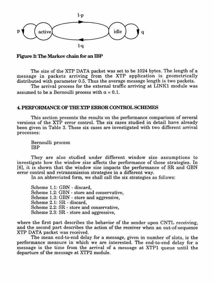
The IBP is also defined over a discrete time axis and it comprises twostates and active state and an idle state, which alternate. The transitionsbetween states are governed by the two state Markov chain as shown in Figure 3.Given that the process is in the active state (or the idle state) at slot i, it willremain in the same state in the next slot i + 1 with probability p (or q), or willchange to the idle state (or the active state) ~th pr?bab~ity 1 - P (or 1 -.Q.)' Duringthe active state, arrivals occur in a Bernoulli fashion WIth the probability that aslot contains an arrival to be a. No arrival occurs if the process is in the idle state
[5].
I-p
p q
l-q
Figure 3: The Markov chain for an ffiP
The size of the XTP DATA packet was set to be 1024 bytes. The length of amessage in packets arriving from the XTP application is geometricallydistributed with parameter 0.5. Thus the average message length is two packets.
The arrival process for the external traffic arriving at LINK1 module wasassumed to be a Bernoulli process with a = 0.1.
4. PERFORMANCE OF THE X'IP ERROR CONrROL SCHEMES
This section presents the results on the performance comparison of severalversions of the XTP error control. The six cases studied in detail have alreadybeen given in Table 3. Those six cases are investigated with two different arrivalprocesses:
Bernoulli processlliP
They are also studied under different window size assumptions toinvestigate how the window size affects the performance of those strategies. In[6], it is shown that the window size impacts the performance of SR and GBNerror control and retransmission strategies in a different way.
In an abbreviated form, we shall call the six strategies as follows:
Scheme 1.1: GBN - discard,Scheme 1.2: GBN - store and conservative,Scheme 1.3: GBN - store and aggressive,Scheme 2.1: SR - discard,Scheme 2.2: SR - store and conservative,Scheme 2.3: SR - store and aggressive,
where the first part describes the behavior of the sender upon CNTL receiving,and the second part describes the action of the receiver when an out-of-sequenceXTP DATA packet was received.
The mean end-to-end delay for a message, given in number of slots, is theperformance measure in which we are interested. The end-to-end delay for amessage is the time from the arrival of a message at XTP1 queue until thedeparture of the message at XTP2 module.

Figure 4 displays the end-to-end delay of a message as the function of userthroughput for the six different cases with Bernoulli arrivals and window size of60 packets. Since the transmission bit error rate assumed is very low, packetcorruption due to transmission error is rare and most of the packet losses arecaused by the buffer overflow. When the throughput is very low, buffer overflow israther unlikely, and thus the number of retransmissions required is small.Owing to the above fact and our assumption of equal processing times for all thesix implementations, the end-to-end delay is almost the same when thethroughput is very low.
The performance difference between the different schemes increases as thethroughput gets larger. For increasing throughput scheme 2.3, "SR - store andaggressive" leads to the smallest delay, and schemes 1.1 and 2.1, "GBN - discard"and "SR - discard" to the largest delay under the given assumptions.
Note that when the receiver discards the out-of-sequence packets, thesender behavior does not affect the performance. Since, when the receiverdiscards the out-of-sequence packets, it requests the sender to retransmiteverything in the current window starting from RSEQ, that is, it forces the senderto exercise GBN retransmission. For this reason the end-to-end delay for theschemes 1.1 and 2.1 turned out to be the same.
When the sender exercises SR and the receiver stores the out-of-sequencepackets, aggressive error control reduces the end-to-end-delay in our experiment.This is due to the fact that the quick acting retransmission request reduces theretransmission delay.
100 .....-------------------.,
00 a Schemes 1.1, 2.1• Scheme 1.2
,,-.... • Scheme 1.300~
0 0 Scheme 2.2~
00'-" so • Scheme 2.3~~~
Q)
~
40
0.14ill
0.04 0.06 0.08 0.10 0.12Throughput (messages/slots)
Mean end-to-end delay as a function of user throughput: Bernoulliarrival
Figure 4:

On the other hand when the sender exercised GBN, aggressive errorcontrol helped decrease the end-to-end delay when the throughput was low, butworsened the performance after the amount of throughput passes a certain pointas we can see from the crosspoint in Figure 4. This behavior can be explained asfollows. As mentioned earlier, most of the packet losses are due to the bufferoverflow under our very low transmission bit error rate assumption. Therefore ifthe quick acting error report from the receiver arrives too early, i.e, before thebuffer overflow situation is relieved completely, it aggravates the overflowsituation and causes another packet losses. This circumstances happen easier ifthe buffer overflow lasts longer, and in turn the buffer overflow is more likely tolast longer under heavy traffic, that is, when the throughput is high. Since the SRsender retransmits only the out-of-sequence packets, the amount of traffic issuedfor a retransmission is rather small and immediate retransmission requests donot harm significantly. For GBN sender, however, too early retransmissionrequests can issue a large amount of traffic at once and degrade the performance.
Since the "GBN" senders retransmit more packets than the "SR" when thereceiver stores the out-of-sequence packets, the schemes 2.2 and 2.3 show thebetter performance than the schemes 1.2 and 1.3 respectively.
Actually, the same number of packets is retransmitted in schemes 1.1 and2.1 where the receiver discards out of sequence packets, and in scheme 1.3 wherethe receiver stores the out of sequence packets. But schemes 1.1 and 2.1 performremarkably worse than scheme 1.3. This can be explained as follows. In scheme1.3 the out-of-sequence packets which had already been received correctly andstored are also retransmitted by the sender. However, in scheme 1.3, the XTPmodule at the receiver side only has to wait for the arrival of the lost packets, and
1200
1000
a Schemes 1.1, 2.1...-.. 800en~ • Scheme 1.20~en • Scheme 1.3"-'
~ Em • Scheme 2.2ct3~
Q) • Scheme 2.3Q
400
0.1200.060 0.080 0.100Throughput (Messages/slot)
O-r--~---r----,.---r----r--...,..------r---..---J
0.040
Figure 5: Mean end-to-end delay as a function ofuser throughput: ffiP anival

can start reassembling new messages with all the packets waiting in the queueas soon as it receives those lost packets. On the other hand, in Schemes 1.1 and2.1, the XTP module at the receiver has to wait for all the discarded out-ofsequence packets.
The result of the same experiment for an ffiP arrival is given in Figure 5.The burstiness of the IBP (C2) was set to 10 in our experiment. The graphs for thelliP arrival show very similar characteristics to those for the Bernoulli arrival,and they can be explained in the same way.
Figure 6 compares the end-to-end delay for the Bernoulli and the IBParrivals. The end-to-end delay for the IBP arrival is larger than that for theBernoulli arrival in the order of tens at high throughput. The difference is biggerin the region of high utilizations, and the performance of scheme 1.1(2.1)degrades most significantly for the ffiP arrival among the six schemes.
1200 .......-------------------......
1000
400
200
a
_ IBP Schemes 1.1, 2.1ID Bernoulli Schemes 1.1,2.1II IBP Scheme 1.2~ Bernoulli Scheme 1.2o mp Scheme 1.3• Bernoulli Scheme 1.3m rsr Scheme 2.213 Bernoulli Scheme 2.2121 IBP Scheme 2.3o Bernoulli Scheme 2.3
0.06 0.08 0.1 0.12Throughput (messages/slot)
Figure 6: Comparison of the mean end-to-end delay: Bernoulli and IDP arrrvals
Different schemes have different optimum window sizes. Tab~e 4 shows theoptimal window size for our six schemes when the throughput IS se.t t~ 0.12messages/slot. 10 different window sizes (from 30 to 120 J?ackets) .were tned In oursimulation, and the figures shown in the table is the WIndow SIze that gave thesmallest end-to-end delay in this experiment.
Table 4Optimal Wmdow Size
SchemeScheme 1.1,2.1Scheme 1.2Scheme 1.3Scheme 2.2Scheme 2.3
Window size5070609090

Rather big window sizes are expected to be the optimums for all theschemes according to this result. This is due to the fact that the sender invokesthe acknowledgement once per window by setting the SREQ bit in the last DATApacket of a window. The sender has to stop and wait for the ALLOC value toincrease at the end of every window, and the percentage of this overhead waitingtime gets larger as the window size gets smaller.
On the other hand, there are several factors that make larger window sizeunprofitable. First thing is the increased retransmission delay: since the senderasks the receiver status once, at the end of a window, retransmission delayincreases as the window size increases for the conservative receiver. Since, whenthere are lost or corrupted packets in the middle of a window, the subsequentpackets arriving out-of-sequence at the receiver side should wait in the receivingXTP queue until the missing ones arrive, retransmission time impacts the endto-end delay consequently.
Secondly, for the GBN sender, the average number of packets to beretransmitted at once increases as the window size increases. Since a suddentraffic increase may cause or lengthen the buffer overflow situation, it worsensthe performance.
140 -..--------------------......
10040 00 80Window Size (packets)
4O-+-----,~---,---~-~--.....-----.---.....-------t
20
120
EI Scheme 1.2~ 100r:n~ • Scheme 1.30....-4r:n'-"~ 00~
....-4OJ
Q
00
Figure 7: Mean end-to-end delay as a function of window size, schemes 2.1 and1.3
Finally the aggressiveness of the receiver can degrade the performance asthe window size gets larger. Figures 7 and 8 show this impact: the schemes 1.3and 2.3 outperform the schemes 1.2 and 2.2 respectively for up to a certainwindow size, but the opposite becomes true for the window sizes larger than that.Since the receiver always set ALLOC value in the outgoing CNTL packet to beequal to DSEQ + constant (window size), the flow control is affected by the errorcontrol strategy very closely. Thus the too early error report explained above can

lengthen or aggrevaga;te the. buffer overflow situation by sliding the window at thes~nder as well as by mcurrmg traffi~ for the retransmission at an inappropriatetime. ~he performance degradation for large window size due to theaggress~vene~sof the receiver is worse when the sender is GBN as we can see bycompanng FIgures 7 and 8.
46,-----------------~
44III Scheme 2.2.....-...
rn • Scheme 2.3~
0...... 42rn'-'"
~.....<J)
Q 40
1001402b-r--.,......---r-...,..--r-----,r----r-~-.....---.-.....--..---I
40 00 100 120Window Size (packets)
Mean end-to-end delay as a function ofwindow size, schemes 2.2 and2.3
Figure 8:
Note that the results given in this section are drawn under certain limitingassumptions. We may have different results with different setting of the windowsize, and with different throughput assumption. There are also other aspects ofwhich we are aware that are of importance in evaluating the performance of SRand GBN error control strategies. These aspects include processing overhead,intermediate buffer requirements, quality of the service provided by he lowerlayers, etc. [6]. Those factors are to be considered in our future studies.
5. SUMMARY AND CONCLUSION
The XTP permits several possibilities in the implementation of errorcontrol mechanism at both ends of a connection. Since the sender has noknowledge of the implementation chosen by the receiver, and vice versa, allpossible combinations of sender and receiver strategies can occur in practice, andit is important to understand the behavior of the various implementation choices.
An application generating variable length messages and requiring orderlydelivery was chosen and modeled on top of XTP. The network connection was asimple link, and the DATA packets were assumed s~ch th~t they could. be lost orcorrupted. A simulation model was implemented Including all the Importantfunctions of XTP error control.

XTP employing the following combinations of sender and receiver strategywere compared:
i) the sender behaves as SRlGBN;ii) the receiver stores/discards out-of-sequence DATA packets, and
aggressively/conservatively reports errors.
The results show that, at the sender side, "SR" yields higher performancethan "GBN" except for the case when the receiver discards the out-of-sequencepackets, the sender behavior does not matter in that case. At the receiver side,"store" results in smaller end-to-end delay than "discard", and theaggressiveness is helpful only when the system load and the window size arewithin a certain limit.
The performance of the XTP error control under two different arrivalprocesses, Bernoulli process and IBP, was studied to investigate the impact of theburstiness of an arrival process. The end-to-end delay increases substantially asthe burstiness increases. The performance degrades most significantly for anincrease in burstiness when the receiver "discards" the out-of-sequence packets.
Different implementation takes different optimum window sizes, and theoptimum window sizes are rather big. "SR - discard" and "GBN - discard" pairstake the smallest optimum window size. The aggressive receiver may performpoorly compared to the conservative receiver when the window size is big.
6. REFERENCES
1. XTP Protocol Definition Revision 3.6, PEl, Santa Barbara, CA, 1992.2. Bernd W. Meister, A Performance Study of the ISO Transport Protocol, IEEE
Trans. Comput., vol. 40, no 3, pp. 253-262, 1991.3. A. Nilsson and M. Huterer, End-to-End Performance of ATM and Private
Broadband Networks, in Proc. The Twenty-Fourth Southeastern Symposiumon System Theory, Greensboro, NC, 1992.
4. J.-R. Louvion, P. Boyer, and A. Gravey, A Discrete-Time Single Server Queuewith Bernoulli Arrivals and Constant Service Time, in Proc. 12thInternational Teletraffic Congress, Torino, 1988.
5. A. Nilsson, F. Lai and H. Perros, An approximate analysis of a bufferless N xN synchronous clos ATM switch, in Proc. Canadian Conference on Electricaland Computer Engineering, Ottawa, Ontario, Canada, pp. 39.1.1-39.1.4, 1990.
6. W. Stallings, Data and Computer Communications, Macmillan PublishingCompany, Macmillan, Inc., N.J., pp. 145-147, pp 480-503, 1991.