Extended Tubular Heat Exchanger Instruction Manual HT36 · 2017-11-03 · HT36-304 software. It...
76
Extended Tubular Heat Exchanger Instruction Manual HT36 ISSUE 4 June 2010
Transcript of Extended Tubular Heat Exchanger Instruction Manual HT36 · 2017-11-03 · HT36-304 software. It...

Extended Tubular Heat Exchanger
Instruction Manual
HT36
ISSUE 4
June 2010

ii
Table of Contents Copyright and Trademarks ...................................................................................... 1
General Overview ....................................................................................................... 2
Equipment Diagrams................................................................................................... 3
Important Safety Information....................................................................................... 6
Introduction.............................................................................................................. 6
Electrical Safety....................................................................................................... 6
Hot Surfaces and Liquids ........................................................................................ 6
Water Borne Hazards .............................................................................................. 6
Description .................................................................................................................. 8
Overview.................................................................................................................. 8
Baseplate................................................................................................................. 8
End Housings .......................................................................................................... 8
Cold Water Circuit Manual Configuration Valves .................................................... 8
Thermocouples........................................................................................................ 9
Connections for Flexible Tubing .............................................................................. 9
Installation................................................................................................................. 10
Advisory................................................................................................................. 10
Installation Process ............................................................................................... 10
Operation .................................................................................................................. 12
Operating the Software.......................................................................................... 12
Operating the Equipment....................................................................................... 22
Equipment Specifications.......................................................................................... 29
I/O Port Pin Connections ....................................................................................... 29
USB Channel Numbers ......................................................................................... 30
Environmental Conditions...................................................................................... 31
Routine Maintenance ................................................................................................ 33
Responsibility ........................................................................................................ 33
General.................................................................................................................. 33
Laboratory Teaching Exercises................................................................................. 34

Table of Contents
Index to Exercises ................................................................................................. 34
Nomenclature ........................................................................................................ 34
Reference Tables .................................................................................................. 36
Calculating Reynolds Number ............................................................................... 37
Exercise A: Indirect Heating/Cooling Demonstration ................................................ 39
Exercise B: Energy Balance and Overall Efficiency.................................................. 45
Exercise C: Cocurrent and Countercurrent Flow ...................................................... 48
Exercise D: Overall Heat Transfer Coefficient .......................................................... 55
Exercise E: Effect of Flow Rate................................................................................. 59
Exercise F: Driving Force.......................................................................................... 65
Exercise G: Project Work .......................................................................................... 70
Contact Details for Further Information ..................................................................... 72
iii


1
Disclaimer This document and all the information contained within it is proprietary to Armfield Limited. This document must not be used for any purpose other than that for which it is supplied and its contents must not be reproduced, modified, adapted, published, translated or disclosed to any third party, in whole or in part, without the prior written permission of Armfield Limited.
Should you have any queries or comments, please contact the Armfield Customer Support helpdesk (Monday to Friday: 0800 – 1800 GMT). Contact details are as follows:
United Kingdom International
(0) 1425 478781 (calls charged at local rate)
+44 (0) 1425 478781 (international rates apply)
Email: [email protected]
Fax: +44 (0) 1425 470916
Copyright and Trademarks Copyright © 2009 Armfield Limited. All rights reserved.
Any technical documentation made available by Armfield Limited is the copyright work of Armfield Limited and wholly owned by Armfield Limited.
Brands and product names mentioned in this manual may be trademarks or registered trademarks of their respective companies and are hereby acknowledged.

General Overview This instruction manual should be used in conjunction with the manual supplied with the HT30XC Heat Exchanger Service Unit.
This Manual provides the necessary information for operating the equipment in conjunction with the HT30XC Service Unit and a connected PC running the Armfield HT36-304 software. It includes a range of Teaching Exercises designed to demonstrate the basic principles of Heat Exchanger theory and use.
This instruction manual describes the operation of the HT36 Extended Tubular Heat Exchanger which must be used in conjunction with the HT30XC Heat Exchanger Service Unit (supplied separately). Details of the service unit are given in a separate instruction manual, which is supplied with the unit. The service unit provides the hot and cold water streams for the heat exchanger along with flow and temperature measurement and control and the facility for computerised data logging of the results.
The HT36 Extended Tubular Heat Exchanger is one model in a range of heat exchangers designed for use with the HT30XC service unit. A full description of the exchanger is provided in the DESCRIPTION section of this manual (page 2-1). Other heat exchangers available in the range include the HT31 Tubular, HT32 Plate, HT33 Shell and Tube, HT34 Jacketed Vessel with Coil and Stirrer and HT37 Extended Plate with Regeneration. These modules are interchangeable on the service unit and each come with their own product manual.
HT36 Extended Tubular Heat Exchanger
2

Equipment Diagrams
Figure 1 Plan View of HT36
3

Armfield Instruction Manual
Figure 2 Side View of HT36
4
Equipment Diagrams
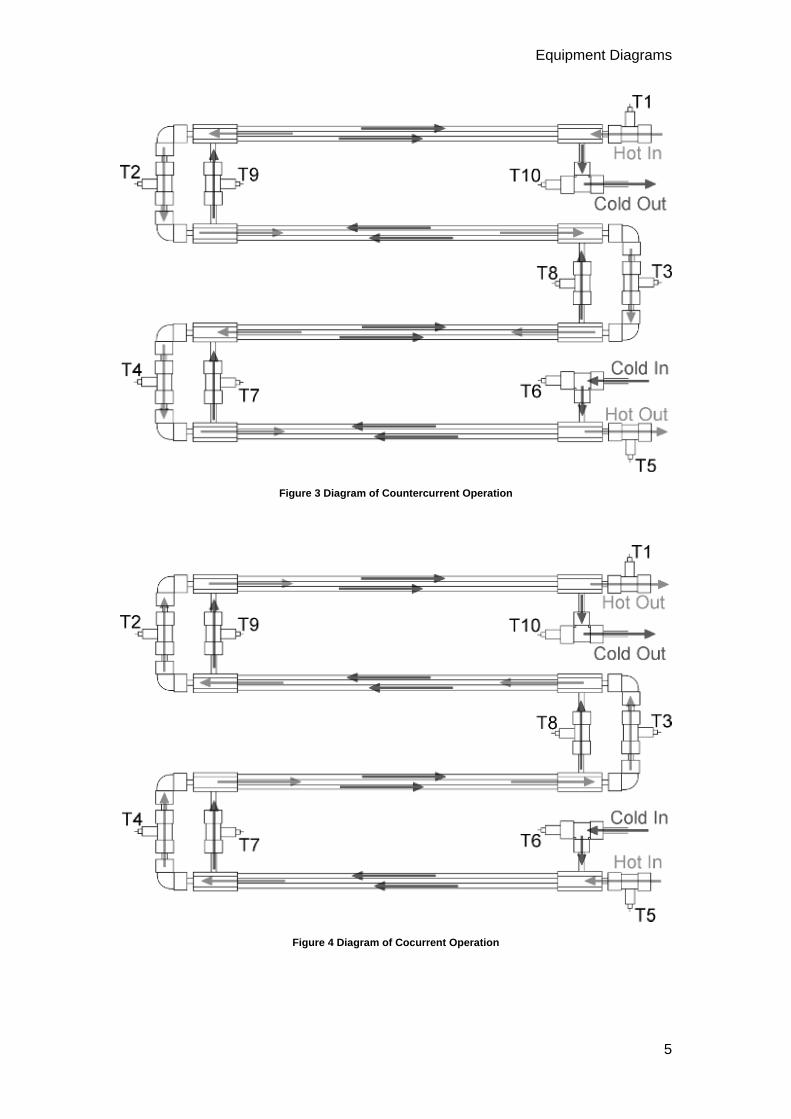
Figure 3 Diagram of Countercurrent Operation
Figure 4 Diagram of Cocurrent Operation
5

6
Important Safety Information
Introduction All practical work areas and laboratories should be covered by local safety regulations which must be followed at all times.
It is the responsibility of the owner to ensure that all users are made aware of relevant local regulations, and that the apparatus is operated in accordance with those regulations. If requested then Armfield can supply a typical set of standard laboratory safety rules, but these are guidelines only and should be modified as required. Supervision of users should be provided whenever appropriate.
Your HT36 Extended Tubular Heat Exchanger has been designed to be safe in use when installed, operated and maintained in accordance with the instructions in this manual. As with any piece of sophisticated equipment, dangers exist if the equipment is misused, mishandled or badly maintained.
Electrical Safety The equipment described in this Instruction Manual operates from a mains voltage electrical supply. It must be connected to a supply of the same frequency and voltage as marked on the equipment or the mains lead. If in doubt, consult a qualified electrician or contact Armfield.
The equipment must not be operated with any of the panels removed.
To give increased operator protection, the unit incorporates a Residual Current Device (RCD), alternatively called an Earth Leakage Circuit Breaker, as an integral part of this equipment. If through misuse or accident the equipment becomes electrically dangerous, the RCD will switch off the electrical supply and reduce the severity of any electric shock received by an operator to a level which, under normal circumstances, will not cause injury to that person.
At least once each month, check that the RCD is operating correctly by pressing the TEST button. The circuit breaker MUST trip when the button is pressed. Failure to trip means that the operator is not protected and the equipment must be checked and repaired by a competent electrician before it is used.
Hot Surfaces and Liquids The heat exchanger is capable of producing temperatures that could cause burns. Do not touch the heat exchanger while it is in operation and allow sufficient time for it to cool after use before handling the exchanger or pipework. If the model needs to be changed it should be handled by the white base on which the exchanger is mounted. Do not open the circulator unit on the service unit except in accordance with the safety instructions included in the HT30XC Heat Exchanger Service Unit product manual.
Water Borne Hazards The equipment described in this instruction manual involves the use of water, which under certain conditions can create a health hazard due to infection by harmful micro-organisms.
For example, the microscopic bacterium called Legionella pneumophila will feed on any scale, rust, algae or sludge in water and will breed rapidly if the temperature of
Important Safety Information
water is between 20 and 45°C. Any water containing this bacterium which is sprayed or splashed creating air-borne droplets can produce a form of pneumonia called Legionnaires Disease which is potentially fatal.
Legionella is not the only harmful micro-organism which can infect water, but it serves as a useful example of the need for cleanliness.
Under the COSHH regulations, the following precautions must be observed:
Any water contained within the product must not be allowed to stagnate, ie. the water must be changed regularly.
Any rust, sludge, scale or algae on which micro-organisms can feed must be removed regularly, i.e. the equipment must be cleaned regularly.
Where practicable the water should be maintained at a temperature below 20°C. If this is not practicable then the water should be disinfected if it is safe and appropriate to do so. Note that other hazards may exist in the handling of biocides used to disinfect the water.
A scheme should be prepared for preventing or controlling the risk incorporating all of the actions listed above.
Further details on preventing infection are contained in the publication “The Control of Legionellosis including Legionnaires Disease” - Health and Safety Series booklet HS (G) 70.
7

8
Description Where necessary, refer to the drawings in the Equipment Diagrams section.
Overview The tubular heat exchanger is the simplest form of heat exchanger and in its basic form consists of two concentric (coaxial) tubes carrying the hot and cold fluids. Heat is transferred to/from one fluid in the inner tube from/to the other fluid in the outer annulus via the metal wall which separates the two fluids.
In this miniature version, four sets of concentric tubes are arranged in series in the form of a coil to reduce the overall length and allow the temperature mid way along both fluid streams to be measured.
In normal operation (see Figure 3 and 4) the hot fluid from the hot water circulator passes through the inner stainless steel tube and cold fluid from the cold water supply passes through the annulus created between each inner metal tube and clear acrylic outer tube. This arrangement minimises heat loss from the exchanger without the need for additional insulation and allows the construction of the exchanger to be viewed.
Baseplate The tubular heat exchanger is mounted on a PVC base plate (1) which incorporates four holes (2) which locate it on four studs at the left hand end of the HT30X service unit. The PVC base plate is secured to the service unit using thumb nuts.
End Housings PVC housings (3), bonded to each end of the clear acrylic outer tubes, incorporate 'O' rings between each inner tube and outer annulus. These provide a liquid seal, accommodate differential expansion between the metal and plastic parts and allow the inner metal tubes to be removed for cleaning. The end housings also incorporate the necessary fittings for sensors to measure the fluid temperatures and connections to the hot and cold water supplies.
Cold Water Circuit Manual Configuration Valves The manual valves on the cold water circuit allow the cold water to be passed through one, two, three or four of the outer annuli, hence allowing active heat exchange through 1, 2, 3 or 4 sections of the Heat Exchanger. This allows the effect of differing heat exchanger lengths to be investigated.

Description
Thermocouples The ten thermocouple temperature sensors (4) are labelled T1 to T10 for identification and each lead is terminated with a miniature thermocouple plug (5) for connection to the appropriate socket on the front of the service unit.
Connections for Flexible Tubing Flexible tubing attached to each fluid inlet/outlet is terminated with a ferrule (6). This allows rapid connection to the appropriate quick release fittings on the HT30XC service unit. The fittings on the HT30XC service unit and HT36 are colour coded red for hot water and blue for cold water to aid identification.
Details of the connections are given in the Installation and Operation sections of this manual.
9

10
Installation
Advisory Before operating the equipment, it must be unpacked, assembled and installed as described in the steps that follow. Safe use of the equipment depends on following the correct installation procedure.
Installation Process The HT36 Extended Tubular Heat Exchanger must be used in conjunction with the HT30X Heat Exchanger Service Unit.
Before mounting the HT36 Extended Tubular Heat Exchanger on a HT30XC Heat Exchanger Service Unit ensure that the service unit has been assembled and connected to the appropriate services as described in the instruction manual supplied with the HT30XC.
1. Check that the HT30XC service unit and the Armfield HT30 range software has been installed as described in the HT30XC product manual (provided with the service unit). The PC on which the software has been installed should be located close to the service unit.
2. Remove the HT36 accessory from any packaging and position the accessory on the HT30XC plinth so that the holes in the HT36 baseplate are located over the studs on the HT30XC.
3. Secure the HT36 to the plinth using the thumb nuts provided.
4. Connect the flexible tubing on the HT36 to the quick-release fittings on the service unit as shown in the following diagram:
5. Direct the tubing carrying the cold water out of the exchanger into a suitable drain.
6. Check that the HT30XC service unit is connected to suitable mains water and mains electricity supplies (as described in the HT30XC manual), and that the water and electricity supplies are switched on.

Installation
7. Check that the HT30XC service unit is connected to the PC using the USB cable provided, and that the PC is switched on. Check that the red and green USB indicator lights on the front panel of the HT30XC are illuminated.
8. Switch on the HT30XC service unit (using the mains switch on the front of the unit), and check that the Emergency Stop button is released (pulled out).
9. Run the HT36 software and select the exercise required. Check that the software reads ‘IFD OK’ in the bottom right-hand corner of the screen.
10. Select the mimic diagram in the software by clicking on the icon.
11. Select the ‘Power On’ switch on the software mimic diagram.
12. Select the Hot Water Pump Control button. In the controller window, set the controller to Manual and then set the Hot Water Pump Speed to 100% using the Manual Control box in the right-hand pane of the window. The hot water pump should begin to operate. Run the pump until the hot water circuit of the heat exchanger has filled with water and all bubbles have been expelled from the circuit. Top up the hot water tank with clean (preferably de-ionised or de-mineralised) water if the level drops below the tip of the level sensor.
13. Set the Hot Water Pump Speed back to 0%. The pump should cease operation. Close the controller window.
14. Fully close the pressure regulator at the cold water inlet. On the mimic diagram screen, set the Cold Water Valve to 100%. The valve should be heard to operate. Gradually open the pressure regulator. Cold water should begin to flow through the cold water circuit. Open the pressure regulator until a flow rate of 4.9 L/min is reached, then lock the regulator setting. Allow water to flow until any bubbles have been eliminated, then set the cold water valve back to 0%.
The HT36 accessory is now installed and primed ready for use.
Refer to the HT30XC manual for further information on the service unit and its operation.
Refer to the Operation section and Laboratory Teaching Exercises for more information on the operation of the HT36 and the investigations that can be performed using this Heat Exchanger. The Teaching Exercises are also available from within the HT36 software Help Text.
11
12
Operation Where necessary, refer to the drawings in the Equipment Diagrams section.
Operating the Software Note: The diagrams in this section are included as typical examples and may not relate specifically to the individual product described in this instruction manual.
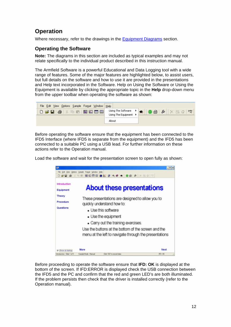
The Armfield Software is a powerful Educational and Data Logging tool with a wide range of features. Some of the major features are highlighted below, to assist users, but full details on the software and how to use it are provided in the presentations and Help text incorporated in the Software. Help on Using the Software or Using the Equipment is available by clicking the appropriate topic in the Help drop-down menu from the upper toolbar when operating the software as shown:
Before operating the software ensure that the equipment has been connected to the IFD5 Interface (where IFD5 is separate from the equipment) and the IFD5 has been connected to a suitable PC using a USB lead. For further information on these actions refer to the Operation manual.
Load the software and wait for the presentation screen to open fully as shown:
Before proceeding to operate the software ensure that IFD: OK is displayed at the bottom of the screen. If IFD:ERROR is displayed check the USB connection between the IFD5 and the PC and confirm that the red and green LED’s are both illuminated. If the problem persists then check that the driver is installed correctly (refer to the Operation manual).
Operation
Presentation Screen - Basics and Navigation
As stated above, the software starts with the Presentation Screen displayed. The user is met by a simple presentation which gives them an overview of the capabilities of the equipment and software and explains in simple terms how to navigate around the software and summarizes the major facilities complete with direct links to detailed context sensitive ‘help’ texts.
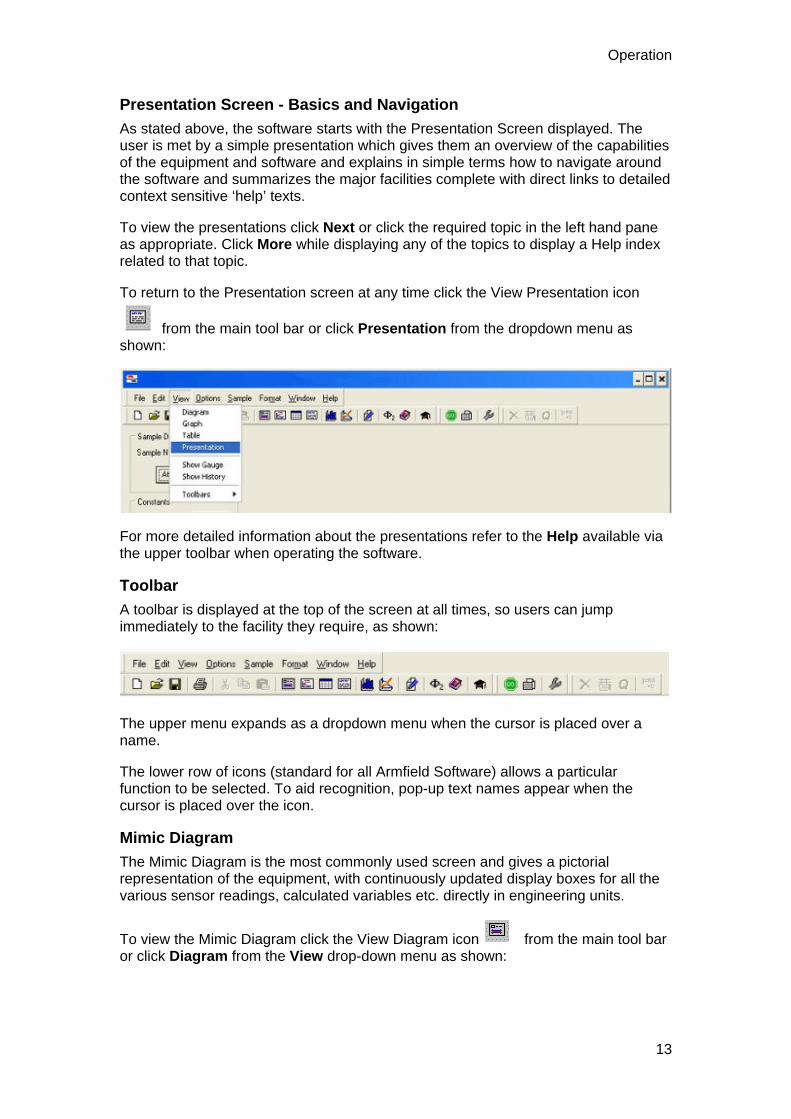
To view the presentations click Next or click the required topic in the left hand pane as appropriate. Click More while displaying any of the topics to display a Help index related to that topic.
To return to the Presentation screen at any time click the View Presentation icon
from the main tool bar or click Presentation from the dropdown menu as shown:
For more detailed information about the presentations refer to the Help available via the upper toolbar when operating the software.
Toolbar
A toolbar is displayed at the top of the screen at all times, so users can jump immediately to the facility they require, as shown:
The upper menu expands as a dropdown menu when the cursor is placed over a name.
The lower row of icons (standard for all Armfield Software) allows a particular function to be selected. To aid recognition, pop-up text names appear when the cursor is placed over the icon.
Mimic Diagram
The Mimic Diagram is the most commonly used screen and gives a pictorial representation of the equipment, with continuously updated display boxes for all the various sensor readings, calculated variables etc. directly in engineering units.
To view the Mimic Diagram click the View Diagram icon from the main tool bar or click Diagram from the View drop-down menu as shown:
13
Armfield Instruction Manual
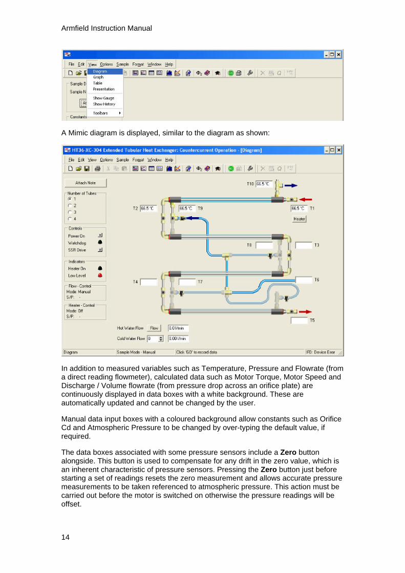
A Mimic diagram is displayed, similar to the diagram as shown:
In addition to measured variables such as Temperature, Pressure and Flowrate (from a direct reading flowmeter), calculated data such as Motor Torque, Motor Speed and Discharge / Volume flowrate (from pressure drop across an orifice plate) are continuously displayed in data boxes with a white background. These are automatically updated and cannot be changed by the user.
Manual data input boxes with a coloured background allow constants such as Orifice Cd and Atmospheric Pressure to be changed by over-typing the default value, if required.
The data boxes associated with some pressure sensors include a Zero button alongside. This button is used to compensate for any drift in the zero value, which is an inherent characteristic of pressure sensors. Pressing the Zero button just before starting a set of readings resets the zero measurement and allows accurate pressure measurements to be taken referenced to atmospheric pressure. This action must be carried out before the motor is switched on otherwise the pressure readings will be offset.
14

Operation
The mimic diagram associated with some products includes the facility to select different experiments or different accessories, usually on the left hand side of the screen, as shown:
Clicking on the appropriate accessory or exercise will change the associated mimic diagram, table, graphs etc to suit the exercise being performed.
Control Facilities in the Mimic Diagram
A Power On button allows the motor to be switched off or on as required. The button always defaults to off at startup. Clicking this button switches the power on (1) and off (0) alternately.
A box marked Motor Setting allows the speed of the motor to be varied from 0 to 100% either stepwise, by typing in values, or using the up / down arrows as appropriate. It is usual to operate the equipment with the motor initially set to 100%, then reduce the setting as required to investigate the effect of reduced speed on performance of the equipment.
When the software and hardware are functioning correctly together, the green LED marked Watchdog Enabled will alternate On and Off. If the Watchdog stops alternating then this indicates a loss of communication between the hardware and software that must be investigated.
Details on the operation of any automatic PID Control loops in the software are included later in this section.
Data Logging Facilities in the Mimic Diagram
There are two types of sampling available in the software, namely Automatic or Manual. In Automatic logging, samples are taken regularly at a preset but variable interval. In Manual logging, a single set of samples is taken only when requested by the operator (useful when conditions have to be changed and the equipment allowed to stabilize at a new condition before taking a set of readings).
15

Armfield Instruction Manual
The type of logging will default to manual or automatic logging as appropriate to the type of product being operated.
Manual logging is selected when obtaining performance data from a machine where conditions need to stabilize after changing appropriate settings. To record a set of set
of data values from each of the measurement sensors click the icon from the
main toolbar. One set of data will be recorded each time the icon is clicked.
Automatic logging is selected when transients need to be recorded so that they can
be plotted against time. Click the icon from the toolbar to start recording, click
the icon from the toolbar to stop recording.
The type of logging can be configured by clicking Configure in the Sample drop-down menu from the upper toolbar as shown:
In addition to the choice of Manual or Automatic sampling, the parameters for Automatic sampling can also be set. Namely, the time interval between samples can be set to the required number of minutes or seconds. Continuous sampling can be selected, with no time limit or sampling for a fixed duration can be set to the required number of hours, minutes or seconds as shown:
Tabular Display
To view the Table screen click the View Table icon from the main tool bar or click Table from the View dropdown menu as shown:
16

Operation
The data is displayed in a tabular format, similar to the screen as shown:
As the data is sampled, it is stored in spreadsheet format, updated each time the data is sampled. The table also contains columns for the calculated values.
New sheets can be added to the spreadsheet for different data runs by clicking the
icon from the main toolbar. Sheets can be renamed by double clicking on the sheet name at the bottom left corner of the screen (initially Run 1, Run 2 etc) then entering the required name.
For more detailed information about Data Logging and changing the settings within the software refer to the Help available via the upper toolbar when operating the software.
Graphical Display
When several samples have been recorded, they can be viewed in graphical format.
17
Armfield Instruction Manual
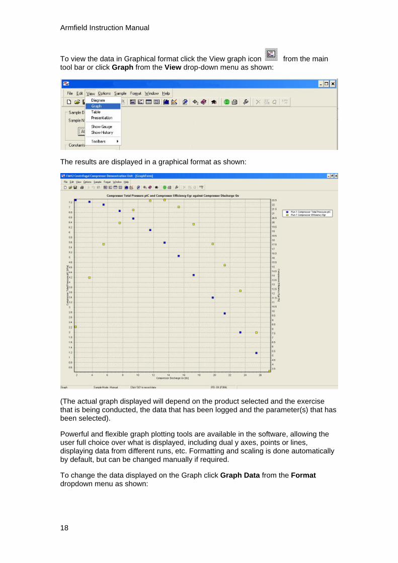
To view the data in Graphical format click the View graph icon from the main tool bar or click Graph from the View drop-down menu as shown:
The results are displayed in a graphical format as shown:
(The actual graph displayed will depend on the product selected and the exercise that is being conducted, the data that has been logged and the parameter(s) that has been selected).
Powerful and flexible graph plotting tools are available in the software, allowing the user full choice over what is displayed, including dual y axes, points or lines, displaying data from different runs, etc. Formatting and scaling is done automatically by default, but can be changed manually if required.
To change the data displayed on the Graph click Graph Data from the Format dropdown menu as shown:
18

Operation
The available parameters (Series of data) are displayed in the left hand pane as shown:
Two axes are available for plotting, allowing series with different scaling to be presented on the same x axis.
To select a series for plotting, click the appropriate series in the left pane so that it is highlighted then click the appropriate right-facing arrow to move the series into one of the windows in the right hand pane. Multiple series with the same scaling can be plotted simultaneously by moving them all into the same window in the right pane.
To remove a series from the graph, click the appropriate series in the right pane so that it is highlighted then click the appropriate left-facing arrow to move the series into the left pane.
The X-Axis Content is chosen by default to suit the exercise. The content can be changed if appropriate by opening the drop down menu at the top of the window.
The format of the graphs, scaling of the axes etc. can be changed if required by clicking Graph in the Format drop-down menu as shown:
19

Armfield Instruction Manual
For more detailed information about changing these settings refer to the Help available via the upper toolbar when operating the software.
PID Control
Where appropriate, the software associated with some products will include a single or multiple PID control loops whereby a function on the product can be manually or automatically controlled using the PC by measuring an appropriate variable and varying a function such as a heater power or pump speed.
The PID loop can be accessed by clicking the box labelled PID or Control depending on the particular software:
A PID screen is then displayed as shown:
20

Operation
The Mode of operation always defaults to Manual control and 0% output when the software is loaded to ensure safe operation of the equipment. If appropriate, the operator can retain manual operation and simply vary the value from 0 to 100% in the Manual Output box, then clicking Apply.
Alternatively, the PID loop can be changed to Automatic operation by clicking the Automatic button. If any of the PID settings need to be changed from the default values then these should be adjusted individually before clicking the Apply button.
The controller can be restored to manual operation at any time by clicking the Manual button. The value in the Manual Output box can be changed as required before clicking the Apply button.
Settings associated with Automatic Operation such as the Setpoint, Proportional Band, Integral Time, Derivative Time and Cycle Time (if appropriate) can be changed by the operator as required before clicking the Apply button.
Clicking Calculations displays the calculations associated with the PID loop to aid understanding and optimization of the loop when changing settings as shown:
21

Armfield Instruction Manual
Clicking Settings returns the screen to the PID settings.
Clicking OK closes the PID screen but leaves the loop running in the background.
In some instances the Process Variable, Control variable and Control Action can be varied to suit different exercises, however, in most instances these boxes are locked to suit a particular exercise. Where the variables can be changed the options available can be selected via a drop-down menu.
Advanced Features
The software incorporates advanced features such as the facility to recalibrate the sensor inputs from within the software without resorting to electrical adjustments of the hardware. For more detailed information about these advanced functions within the software refer to the Help available via the upper toolbar when operating the software.
Operating the Equipment Before operating the equipment, ensure that the HT36 Extended Tubular Heat Exchanger and the HT30XC base unit have been assembled and installed as shown in the separate Installation section.
Connecting the heat exchanger to the service unit
The connections required are as follows:
22

Operation
The connectors are colour coded on both the service unit and the heat exchanger accessory, with blue for cold water and red for hot water.
Configuring the heat exchanger for countercurrent and cocurrent flow
The cold water supply always enters the heat exchanger at the same end. The hot water supply may be configured to enter at the same end as the cold water flow (cocurrent flow), or at the opposite end (countercurrent flow). The direction of the hot water flow is set by the direction of the hot water pump. This is controlled by the software, and thus countercurrent flow may be set by selecting a ‘Countercurrent’ software exercise and cocurrent flow by selecting a ‘Cocurrent’ exercise.
Configuring the number of active heat exchanger tubes
The heat exchanger may be used with one, two, three or four active sections. To configure the exchanger, close each manual valve on the heat exchanger (but NOT the valves on the HT30XC service unit) by turning the handle at right-angles to the tube. Then open the appropriate valve as follows:
4 tubes
Open the lower right valve on the exchanger (turn handle in line with tube)
3 tubes
Open the lower left valve on the exchanger
23

Armfield Instruction Manual
2 tubes
Open the upper right valve on the exchanger
1 tube
Open the upper left valve on the exchanger
If you are uncertain as to the correct valve settings, run the software and select the number of active tubes you require. The software will then show an image with the correct valve settings on the display screen.
24
Operation
Configuring the software to match the number of active tubes
The cocurrent and countercurrent exercises in the software (not the Project Work exercises) include a panel on the left when the number of active sections may be selected. When one of these options is selected, the software screen displays the manual valve settings for the cold water circuit, and the inactive outer annuli (i.e. those through which the cold water does not flow) are dimmed on the display.
Priming the hot water circuit
The hot water circuit should be filled with deionised or demineralised water if possible, to minimise scale and reduce the need for cleaning. If this is not available then the water used should be clean. To prime the hot water circuit, fill the hot water vessel on the HT30XC service unit with water by carefully removing the lid (without damaging the level sensor attached to it) and pouring in the water. The vessel should be filled until it covers the tip of the level sensor mounted on the lid of the vessel.
Check that the accessory has been connected to the service unit as described above, and that the service unit is connected to a suitable PC. Switch on the service unit using the mains switch on the front of the unit.
Run the HT36 software (any exercise). Switch the service unit from standby to on by selecting the ‘Power On’ switch on the software mimic diagram screen.
Select the hot water flow rate control button. In the controller window, set the controller to ‘Manual’ and gradually increase the manual control setting to 100% using the arrow buttons. Check that the pump starts to operate and water begins to flow through the hot water system. The hot water vessel may need topping up as water enters the rest of the system, to keep the tip of the level sensor covered.
Select the heater control button, and set the controller to Automatic with a Set Point of 80°C (maximum operating temperature- do not operate at this temperature for more than a few minutes, as prolonged high temperatures may cause softening and warping of the acrylic outer heat exchanger tube). The heater should begin to operate. As the water heats, dissolved air will be released from the hot water. The resulting bubbles, along with any air still remaining in the system after the initial priming process, will be gradually flushed from the system and into the hot water vessel as hot water continues to flow through the system. They may be encouraged to move by gently squeezing the flexible tubing.
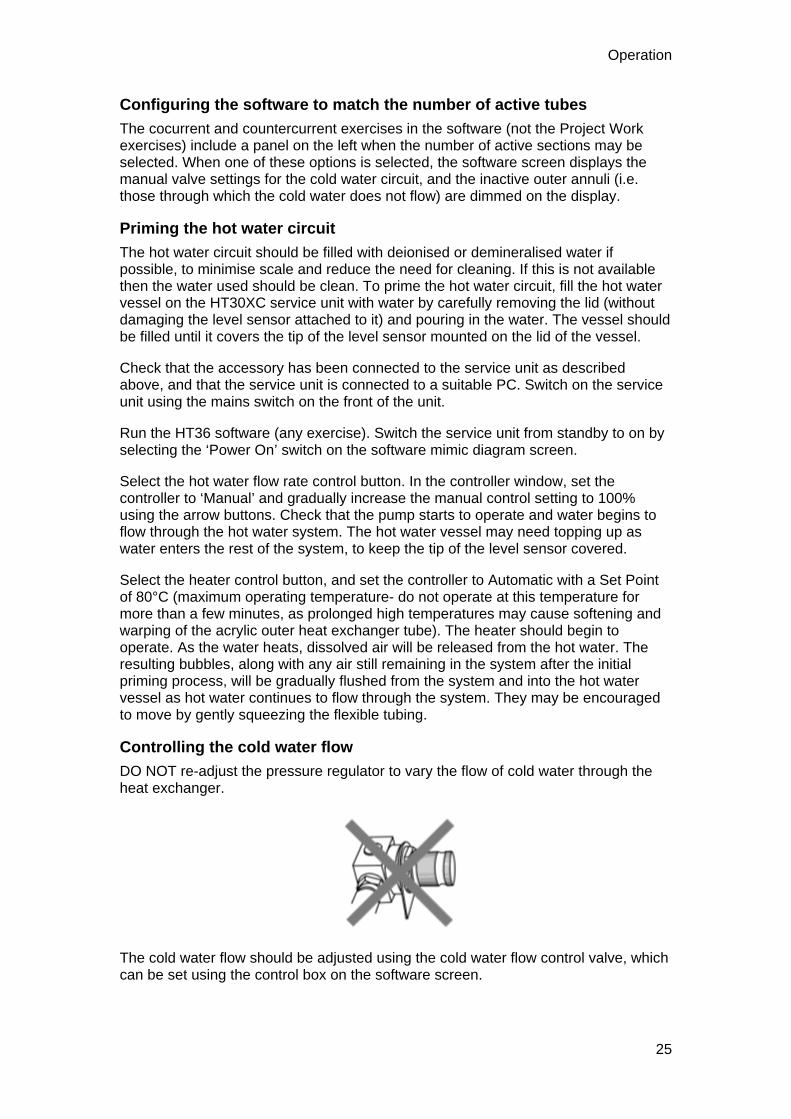
Controlling the cold water flow
DO NOT re-adjust the pressure regulator to vary the flow of cold water through the heat exchanger.
The cold water flow should be adjusted using the cold water flow control valve, which can be set using the control box on the software screen.
25

Armfield Instruction Manual
Controlling the hot water flow
The hot water flow rate can be controlled using the hot water pump, which can be set using the PID controller in the software. To adjust the controller Set Point or PID values, click on the hot water ‘Flow’ button on the software screen to open the controller window, and select ‘Automatic’. For approximate default values of the controller settings, the Proportional Band may be set to 100%, with an Integral time of 3s and Derivative time of 0s (these values are set by default and in most cases the flow rate can be controlled by simply entering the required flow rate in the Set Point box). The settings required for the exercises included in this manual described in the individual Laboratory Teaching Exercises and in the software Help Text.
Setting the hot water temperature controller
The hot water temperature can be controlled using the heater (SSR drive) in the hot water vessel, which is operated using the ‘Heater’ controller in the software. Selecting this controller button opens the controller window, and the controller should then be set to Automatic. The Proportional Band should be set to 100%, with Integral and Derivative times of 0s. The Set Point value (i.e. the required temperature) should then be entered in the appropriate box.
By default, the heater controller compares the Set Point value to the inlet temperature of the hot water stream as it enters the heat exchanger, and adjusts the proportion of heating time until the inlet temperature matches the required Set Point.
The hot water stream always flows through every section of tubing, but depending on the configuration of the cold water supply, not every section of the heat exchanger will be part of the heat exchange process. In cocurrent flow, the point at which the hot water enters the active section of the heat exchanger will differ depending on the number of active tubes. By default, the controller is set to monitor the temperature T5 (the initial inlet point), which will give reasonable accuracy. However, for greater accuracy the controller may be reconfigured to monitor the inlet temperature for the active section of the heat exchanger. To change the temperature monitored, open the controller window and select the required thermocouple from the ‘Process Variable’ drop-down list.
Measuring the water temperatures
The water temperatures are displayed on the mimic diagram screen. The values displayed reflect the configuration selected, i.e. the number of tubes through which the hot and cold water streams are flowing. The correct number of tubes should be selected in order to display the relevant temperatures.
Prevention of bubbles in the hot water circuit
Before taking results, ensure that all air bubbles have been expelled from the water via the priming vessel. Note that as the water is heated for the first time the air dissolved in the water will continue to be released. It is therefore sensible to heat the water to the maximum intended operating temperature before carrying out tests at lower temperatures, as described in Priming the Hot Water Circuit.
The hot water vessel is equipped with a level sensor, which will cut electrical power to the heating element and pump until the system is primed.
26

Operation
Effect of cold water temperature on heat exchange
The temperature of the water entering the equipment from the mains cold water supply will affect the range of range of hot and cold water flowrates and/or the temperature of the hot water that can be achieved when using the equipment.
The heater in the hot water circulator has a nominal rating of 2 kW, limiting the heat exchange from the hot water stream to the cold water stream to this value. If the temperature of the hot water will not reach the value set on the PID controller with the controller providing full power to the heater then this indicates that the limit of the heater power has been reached. This is not a problem and simply requires an adjustment to the settings on the equipment.
To operate with the same flowrates then a lower hot water temperature must be accepted (reduced differential temperature between the two fluid streams). To operate with an elevated hot water temperature then one or both of the flowrates must be reduced until the demand on the heater is less than 2 kW.
Some of the settings in the practical training exercises may be affected in this way. An excessively warm mains water supply will not present any problems since the temperature difference between the two fluid streams will be reduced. This would allow the hot water stream to be increased to even higher temperatures than quoted. An excessively cold mains water supply may mean that the hot water temperature quoted cannot be achieved because of the increased temperature difference between the two fluid streams. Operation at reduced hot water temperature or reduced flowrate must then be accepted.
Connecting HT30X or HT30XC to a PC
The USB port on the right hand side of the console allows the voltage signals from the sensors, valve and pump to be sent to the USB port of a suitable PC. The WindowsTM based HT36 software allows control of the HT30XC service unit, and logging of the sensor outputs from the heat exchanger. The software should be installed on a PC running Windows™ 98 or later, which must have an available USB port for connection to the Ht30XC. The software MUST be installed before connecting the PC to the service unit- installation is described in the product Installation section.
Once the software has been installed and the PC has been connected to the service unit with the HT36 accessory in place and connected as described in the Installation section, the HT36 software should be run (Select Armfield Heat Exchanger Software from your Start menu and select HT36). The software will then present a selection of exercises to choose from. The Laboratory Teaching Exercises provided in this manual describe the appropriate exercise to pick (either Countercurrent or Cocurrent). If performing independent study work or other project work that does not use a standard configuration then one of the two Project Work exercises may be chosen instead.
Use of the software for controlling the equipment and logging the sensor data is described in the Laboratory Teaching Exercises. This information is also available in the Software Help Text, accessible from within the software. It is recommended that students perform at least a representative selection of the Laboratory Teaching Exercises, to become familiar with the equipment and the use of the software, before attempting independent project work.
27

Armfield Instruction Manual
Operation of Guest push fittings
Guest push fittings are used on the equipment for convenience when changing the configuration or removing items for cleaning. The diagrams below show the simple operation of these fittings:
To connect to a quick release fitting
Align the parallel section of the rigid tube with the loose collet on the quick release fitting…
and push firmly until the tube stops.
An 'O' ring inside the fitting provides a leak-proof seal between the tube and the fitting. The collet grips the tube and prevents it from being pulled out from the fitting.
To disconnect from a quick release fitting
Push the loose collet against the body of the quick release fitting while pulling the tube firmly.
The tube will slide out from the fitting. The tube/fitting can be assembled and disassembled repeatedly without damage.
28

29
Equipment Specifications
I/O Port Pin Connections To allow access to the measurement signals in applications other than when using the apparatus with an Armfield data logger interface and associated software, the connections to the 50 way connector are listed below for information:
Pin No Channel No Signal Function
Analog Inputs (0-5 V dc):
1 Ch 0 Temperature 1 (0-200°C)
2 Ch 1 Temperature 2 (0-200°C)
3 Ch 2 Temperature 3 (0-200°C)
4 Ch 3 Temperature 4 (0-200°C)
5 Ch 4 Temperature 5 (0-200°C)
6 Ch 5 Temperature 6 (0-200°C)
7 Ch 6 Temperature 7 (0-200°C)
8 Ch 7 Temperature 8 (0-200°C)
9 Ch 8 Temperature 9 (0-200°C)
10 Ch 9 Temperature 10 (0-200°C)
11 Ch 10 Flow F1 (0-3 L/min)
12 Ch 11 Flow F2 (0-1.5 L/min)
13-21 Not used
Analog Outputs (0-5V dc):
22 Not used
23 Ch 0 Hot water pump speed
24 Ch 1 Cold water valve setting
25 Not used

Armfield Instruction Manual
Digital Inputs (0-5V dc):
26-27 Not Used
30 Ch 2 Level Monitor
21-32 Not used
33 Ch 4 Thermostat Monitor
34-37 Not used
Digital Outputs (0-5V dc):
38 Ch 0 Power On
39 Ch 1 Watchdog pulse
40 Ch 2 SSR drive
41 Ch 3 Pump direction
42 Digital Ground
43 Ch 4 Stirrer on
44 Ch 5 Aux heater on
47-48 Digital Ground
49-50 Not Used
USB Channel Numbers The HT36 includes Windows™-compatible software for full remote operation of the equipment and data logging of all output signals. However, users may prefer to write their own software for control and data logging, and for the convenience of those wishing to do so, Armfield has provided additional USB drivers allowing operation of the equipment via the USB socket on the HT30XC console. The relevant channel numbers for the HT36 are as follows:
Channel No Signal Function
Analog Inputs (0-5 V dc):
Channel 0 Temperature T1 (0 to133°C = -5 to +5 V)
Channel 1 Temperature T2 (0 to133°C = -5 to +5 V)
30

Equipment Specifications
Channel 2 Temperature T3 (0 to133°C = -5 to +5 V)
Channel 3 Temperature T4 (0 to133°C = -5 to +5 V)
Channel 4 Temperature T5 (0 to133°C = -5 to +5 V)
Channel 5 Temperature T6 (0 to133°C = -5 to +5 V)
Channel 6 Temperature T7 (0 to133°C = -5 to +5 V)
Channel 7 Temperature T8 (0 to133°C = -5 to +5 V)
Channel 8 Temperature T9 (0 to133°C = -5 to +5 V)
Channel 9 Temperature T10 (0 to133°C = -5 to +5 V)
Channel 10 Hot water flow Fhot (0 to 25 L/min = 0 to 5 V)
Channel 11 Cold water flow Fcold (0 to 5 L/min = 0 to 5 V)
Analog Outputs (0-5V dc):
Channel 0 Hot water pump speed
Channel 1 Cold water valve setting
Digital Inputs (0-5V dc):
Channel 0 Not Used
Channel 1 Not Used
Channel 2 Level monitor
Channel 4 Thermostat monitor
Digital Outputs (0-5V dc):
Channel 0 Power on required (1 = on)
Channel 1 Watchdog pulse (1 pulse every 5 seconds)
Channel 2 SSR drive (1 = on)
Channel 3 Pump direction (1 = cocurrent)
Environmental Conditions This equipment has been designed for operation in the following environmental conditions. Operation outside of these conditions may result reduced performance, damage to the equipment or hazard to the operator.
31

Armfield Instruction Manual
a. Indoor use;
b. Altitude up to 2000 m;
c. Temperature 5 °C to 40 °C;
d. Maximum relative humidity 80 % for temperatures up to 31 °C, decreasing linearly to 50 % relative humidity at 40 °C;
e. Mains supply voltage fluctuations up to ±10 % of the nominal voltage;
f. Transient over-voltages typically present on the MAINS supply;
Note: The normal level of transient over-voltages is impulse withstand (over-voltage) category II of IEC 60364-4-443;
g. Pollution degree 2.
Normally only nonconductive pollution occurs.
Temporary conductivity caused by condensation is to be expected.
Typical of an office or laboratory environment
32

33
Routine Maintenance
Responsibility To preserve the life and efficient operation of the equipment it is important that the equipment is properly maintained. Regular maintenance of the equipment is the responsibility of the end user and must be performed by qualified personnel who understand the operation of the equipment.
General In addition to regular maintenance the following notes should be observed:
1. The HT30XC service unit should be disconnected from the electrical and water supplies when not in use.
2. Water should be drained from the inner tubes and outer annulus of the HT36 heat exchanger after use to minimise build up of scale or fouling on the heat exchange surfaces.
The water can be drained by simply disconnecting the four flexible tubes connecting the exchanger to the HT30XC service unit.
3. Any build up of scale inside the heat exchanger can be removed by passing a mild descaler through the exchanger then flushing thoroughly with clean water.
Any stubborn deposits can be eliminated by manual cleaning having carefully removed the inner tube from the outer annulus. To remove the metal tube for cleaning, disconnect the quick release fittings from each end of the metal tube then pull the tube out of the assembly taking care not to damage the 'O' ring seals. After cleaning, lubricate the 'O' ring seals with a small amount of wetting agent before re-inserting the metal tube and replacing the quick release fittings.
Note: The PVC housing at each end of the acrylic tube is bonded to the acrylic tube and cannot be removed.
If it is necessary to replace the 'O' ring seals the replacements should have the following specification:
Material Nitrile rubber
Diameter To suit 3/8" shaft
Section 0.103" section
For reference the Dowty part number is 200-110-4470
Laboratory Teaching Exercises
Index to Exercises Exercise A - Indirect Heating/Cooling Demonstration
Exercise B - Energy Balance and Overall Efficiency
Exercise C - Cocurrent and Countercurrent Flow
Exercise D - Overall Heat Transfer Coefficient
Exercise E: Effect of Flow Rate
Exercise F: Driving Force
Exercise G: Project Work
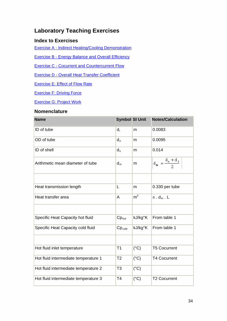
Nomenclature
Name Symbol SI Unit Notes/Calculation
ID of tube di m 0.0083
OD of tube do m 0.0095
ID of shell ds m 0.014
Arithmetic mean diameter of tube dm m
Heat transmission length L m 0.330 per tube
Heat transfer area A m2 . dm . L
Specific Heat Capacity hot fluid Cphot kJ/kg°K From table 1
Specific Heat Capacity cold fluid Cpcold kJ/kg°K From table 1
Hot fluid inlet temperature T1 (°C) T5 Cocurrent
Hot fluid intermediate temperature 1 T2 (°C) T4 Cocurrent
Hot fluid intermediate temperature 2 T3 (°C)
Hot fluid intermediate temperature 3 T4 (°C) T2 Cocurrent
34
Laboratory Teaching Exercises
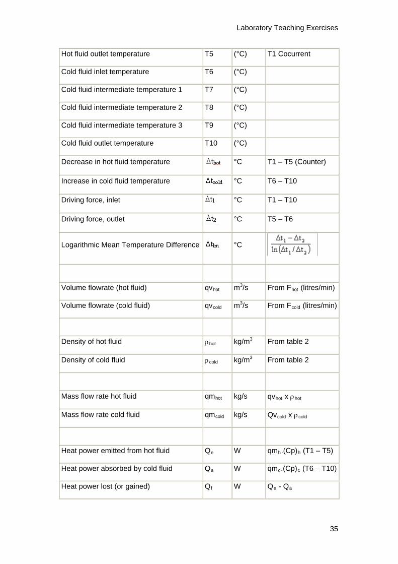
Hot fluid outlet temperature T5 (°C) T1 Cocurrent
Cold fluid inlet temperature T6 (°C)
Cold fluid intermediate temperature 1 T7 (°C)
Cold fluid intermediate temperature 2 T8 (°C)
Cold fluid intermediate temperature 3 T9 (°C)
Cold fluid outlet temperature T10 (°C)
Decrease in hot fluid temperature °C T1 – T5 (Counter)
Increase in cold fluid temperature °C T6 – T10
Driving force, inlet °C T1 – T10
Driving force, outlet °C T5 – T6
Logarithmic Mean Temperature Difference °C
Volume flowrate (hot fluid) qvhot m3/s From Fhot (litres/min)
Volume flowrate (cold fluid) qvcold m3/s From Fcold (litres/min)
Density of hot fluid hot kg/m3 From table 2
Density of cold fluid cold kg/m3 From table 2
Mass flow rate hot fluid qmhot kg/s qvhot x hot
Mass flow rate cold fluid qmcold kg/s Qvcold x cold
Heat power emitted from hot fluid Qe W qmh.(Cp)h (T1 – T5)
Heat power absorbed by cold fluid Qa W qmc.(Cp)c (T6 – T10)
Heat power lost (or gained) Qf W Qe - Qa
35

Armfield Instruction Manual
Overall Efficiency %
Temperature Efficiency hot fluid hot %
Temperature Efficiency cold fluid cold %
Mean Temperature Efficiency mean %
Overall Heat Transfer Coefficient U W/m2°C
Reference Tables
Table 1
Specific Heat Capacity of Water (Cp kJ/kg°K)
Table 2
Density of Water ( kg/m3)
36

Laboratory Teaching Exercises
Calculating Reynolds Number For tubular heat exchangers, when using Reynold’s Number to describe the characteristics of the exchanger it is usual to calculate it for the process fluid, which is generally the fluid flowing through the inner tube. It is also possible to calculate a Reynold’s Number for fluid flowing through the outer shell. This may sometimes be of interest, for example in systems where one fluid has a high viscosity, which may provide more efficient heat exchange when directed through the outer shell if the flow is sufficiently turbulent.
Reynold’s Number for a tubular heat exchanger may be calculated as follows:
For the Inner Tube (hot fluid if configured as described in the manual):
Where t = Density of fluid in inner tube at temp Ttave (kg/m³)
ut = Fluid velocity in the inner tube (m/s)
di = Tube ID = Inner diameter of tube (m)
= 892.5 x 10⁻⁶ m (see dimensions below)
t = Dynamic viscosity of fluid in inner tube at temp Ttave (10-3 m2/s )
where Ttave = Average temperature of fluid within inner tube (K)
For the Outer Tube (cold fluid if configured as described in the manual):
Where s = Density of fluid in outer shell at temp Tsave (kg/m³)
37
Armfield Instruction Manual
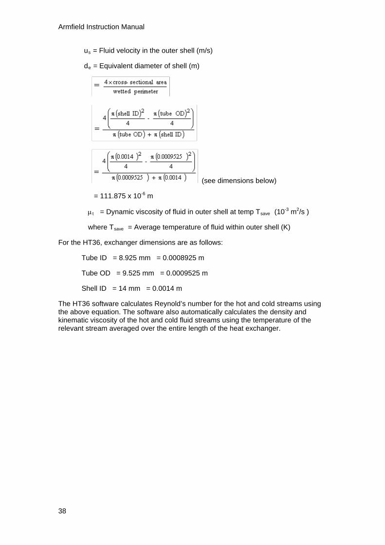
us = Fluid velocity in the outer shell (m/s)
de = Equivalent diameter of shell (m)
(see dimensions below)
= 111.875 x 10⁻⁶ m
t = Dynamic viscosity of fluid in outer shell at temp Tsave (10-3 m2/s )
where Tsave = Average temperature of fluid within outer shell (K)
For the HT36, exchanger dimensions are as follows:
Tube ID = 8.925 mm = 0.0008925 m
Tube OD = 9.525 mm = 0.0009525 m
Shell ID = 14 mm = 0.0014 m
The HT36 software calculates Reynold’s number for the hot and cold streams using the above equation. The software also automatically calculates the density and kinematic viscosity of the hot and cold fluid streams using the temperature of the relevant stream averaged over the entire length of the heat exchanger.
38

39
Exercise A: Indirect Heating/Cooling Demonstration
Objective
To demonstrate indirect heating or cooling by transfer of heat from one fluid stream to another when separated by a solid wall (fluid to fluid heat transfer)
Method
By measuring the changes in temperature of two separate streams of water flowing through the inner tube and outer annulus of a tubular (concentric double pipe) heat exchanger
Equipment Required
HT30XC Computer Compatible Heat Exchanger Service Unit
HT36 Extended Tubular Heat Exchanger
PC running MicrosoftTM Windows 98 or XP with available USB port
Equipment set-up
Before proceeding with the exercise, ensure that the equipment has been prepared as follows:
Locate the HT36 Extended Tubular Heat Exchanger on the HT30XC Service Unit and secure it using the knurled fixings.
Connect the ten thermocouples on the heat exchanger to the appropriate sockets on the front of the HT30XC plinth (labelled T1 – T10).
Connect the hot and cold water supplies as follows:
Ensure that a cold water supply is connected to the inlet of the pressure regulating valve.
Ensure that the service unit is connected to an electrical supply.
Switch on the front Mains switch.
Armfield Instruction Manual
Ensure that the service unit is connected to a suitable PC, and run the HT36 software. Select the Countercurrent exercise.
Switch the service unit from Standby to On by selecting the Power On switch on the mimic diagram screen.
Prime the hot and cold water circuits as described in the Operation section.
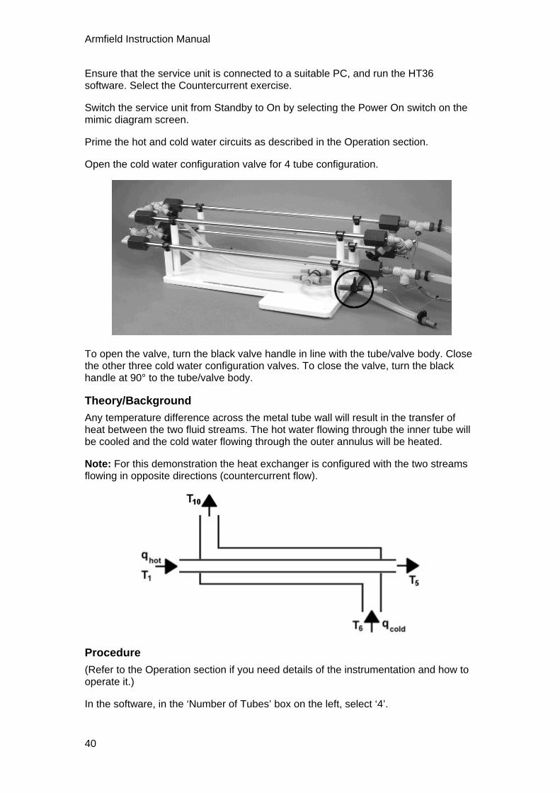
Open the cold water configuration valve for 4 tube configuration.
To open the valve, turn the black valve handle in line with the tube/valve body. Close the other three cold water configuration valves. To close the valve, turn the black handle at 90° to the tube/valve body.
Theory/Background
Any temperature difference across the metal tube wall will result in the transfer of heat between the two fluid streams. The hot water flowing through the inner tube will be cooled and the cold water flowing through the outer annulus will be heated.
Note: For this demonstration the heat exchanger is configured with the two streams flowing in opposite directions (countercurrent flow).
Procedure
(Refer to the Operation section if you need details of the instrumentation and how to operate it.)
In the software, in the ‘Number of Tubes’ box on the left, select ‘4’.
40

Exercise A
Set a cold water flow rate of approximately 1 l/min by adjusting the arrows on the side of the cold water flow rate display box.
Check the cold water inlet temperature T6 (shown in a display box on the mimic diagram screen).
Set the temperature controller to a set point approximately 30oC above the cold water inlet temperature (e.g. if T6 is 15°C then choose a Set Point of 45°C). Check that the Proportional Band is set to 100, the Integral Time to 3 and the Derivative Time to 0, and change them accordingly if they do not match these values.
Click on the Heater control box. In the heater controller window, type in the required value for the Set Point, and then select Automatic control from the selection on the top right of the window. Check that the Proportional Band is set to 5, the Integral Time to 200 and the Derivative Time to 0, and change them accordingly if they do not match these values. Click on ‘Apply’ and then ‘OK’ to close the window.
Set the hot water flow controller to give 3 l/min: click on the ‘Flow’ controller box, and type the required Set Point (3.0 l/min) into the Set Point box. The Proportional Band should be 100% and the Integral time should be 3s. The Derivative time should be 0s. Select ‘Automatic’ in the top right of the controller window, then ‘Apply’. Select ‘OK’ to close the controller window.
Allow the heat exchanger to stabilise (monitor the temperatures on the mimic diagram display).
When the temperatures are stable select the icon on the top toolbar to record the following:
T1, T2, T3, T4, T5, T6, T7, T8, T9, T10, Fhot, Fcold.
Adjust the cold water control valve to give 2 litres/min, using the arrow buttons on the side of the display box.
Create a new results sheet using the icon.
Check that the correct number of tubes is still selected on the mimic diagram.
Allow the heat exchanger to stabilise then repeat the above readings by selecting the
icon.
If there is ample time in which to take results, then other combinations of hot and cold water flow rates may be investigated. Remember to create a new results sheet for
each set of results by selecting the icon.
Open the heater controller window and adjust the controller from ‘Automatic’ to ‘Off’. Open the hot water pump controller window and change the set point to 0 l/min. Set the cold water flow control valve to 0%.
Close the manual flow valve for four tube configuration and open the valve for three tube configuration:
41
Armfield Instruction Manual
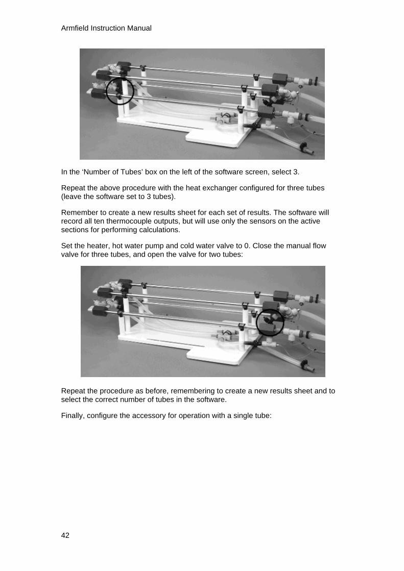
In the ‘Number of Tubes’ box on the left of the software screen, select 3.
Repeat the above procedure with the heat exchanger configured for three tubes (leave the software set to 3 tubes).
Remember to create a new results sheet for each set of results. The software will record all ten thermocouple outputs, but will use only the sensors on the active sections for performing calculations.
Set the heater, hot water pump and cold water valve to 0. Close the manual flow valve for three tubes, and open the valve for two tubes:
Repeat the procedure as before, remembering to create a new results sheet and to select the correct number of tubes in the software.
Finally, configure the accessory for operation with a single tube:
42

Exercise A
Repeat the above procedure.
Set the heater, pump and cold water flow valve to 0, then select the Power On switch to set the HT30XC service unit to Standby.
Results and Calculations
For each set of readings your raw data is presented in a table using the following headings:
Hot fluid volume flowrate qvhot (m3/s) From Fhot (litres/min)
Hot fluid inlet temperature T1 (°C)
Hot fluid mid temperature 1 T2 (°C)
Hot fluid mid temperature 2 T3 (°C)
Hot fluid mid temperature 3 T4 (°C)
Hot fluid outlet temperature T5 (°C)
Cold fluid volume flowrate qvcold (m3/s) From Fcold (litres/min)
Cold fluid inlet temperature T6 (°C)
Cold fluid mid temperature 1 T7 (°C)
Cold fluid mid temperature 2 T8 (°C)
Cold fluid mid temperature 3 T9 (°C)
Cold fluid outlet temperature T10 (°C)
You should also estimate and record the experimental errors for these measurements.
43

Armfield Instruction Manual
For each set of readings your derived results are also tabulated under the following headings:
Reduction in hot fluid temperature = T1 – T5 (oC)
Increase in cold fluid temperature = T10 – T6 (oC)
Estimate the cumulative influence of the experimental errors on your calculated
values for and .
Compare the changes in temperature at the different flowrates.
Conclusion
You have demonstrated how, using a tubular heat exchanger, a stream of cold fluid can be heated by indirect contact with another fluid stream at a higher temperature (the fluid streams being separated by a wall which conducts heat). This transfer of heat results in a cooling of the hot fluid.
Comment on the changes in and when the flow of cold water is increased. The consequence of these changes will be investigated in a later exercise.
Comment on the effect of differing numbers of tubes (and therefore differing lengths of tubular heat exchanger).
Note: To save time Exercise B can be carried out using the readings obtained from this exercise.
44

45
Exercise B: Energy Balance and Overall Efficiency
Objective
To perform an energy balance across a Tubular Heat Exchanger and calculate the Overall Efficiency at different fluid flowrates.
Method
By measuring the changes in temperature of the two separate fluid streams in a tubular heat exchanger and calculating the heat energy transferred to/from each stream to determine the Overall Efficiency.
Equipment Required
As Exercise A.
Optional Equipment
As Exercise A.
Equipment set-up
If using the results from Exercise A then the equipment is not required.
If previous results are not available refer to the Set-up and Procedure sections of Exercise A.
Theory/Background
Note: For this demonstration the heat exchanger is configured for countercurrent flow (the two fluid streams flowing in opposite directions).
Mass flow rate (qm) = Volume flow rate (qv) x Density of fluid () (kg/s)
Heat power (Q) = Mass flow rate (qm) x specific heat (Cp) x change in temperature
(W)
Therefore:
Heat power emitted from hot fluid Qe = qmh.(Cp)h (T1 – T5) (W)
Heat power absorbed by cold fluid Qa = qmc.(Cp)c (T6 – T10) (W)
Heat power lost (or gained) Qf = Qe - Qa (W)
Overall Efficiency (%)
Theoretically Qe and Qa should be equal. In practice these differ due to heat losses or gains to/from the environment.
Note: In this exercise the cold fluid is circulated through the outer annulus, if the average cold fluid temperature is above the ambient air temperature then heat will be lost to the surroundings resulting in <100%. If the average cold fluid temperature is below the ambient temperature then heat will be gained resulting in >100%.

Armfield Instruction Manual
Procedure
Use the results obtained from Exercise A.
Results and Calculations
For each set of readings your raw data is presented in a table using the following headings:
Hot fluid volume flowrate qvhot (m3/s) From Fhot (litres/min)
Hot fluid inlet temperature T1 (°C)
Hot fluid mid temperature 1 T2 (°C)
Hot fluid mid temperature 2 T3 (°C)
Hot fluid mid temperature 3 T4 (°C)
Hot fluid outlet temperature T5 (°C)
Cold fluid volume flowrate qvcold (m3/s) From Fcold (litres/min)
Cold fluid inlet temperature T6 (°C)
Cold fluid mid temperature 1 T7 (°C)
Cold fluid mid temperature 2 T8 (°C)
Cold fluid mid temperature 3 T9 (°C)
Cold fluid outlet temperature T10 (°C)
You should also estimate and record the experimental errors for these measurements.
For each set of readings, the software calculates the following variables. These may also be obtained from the Reference Tables:
Specific heat of hot fluid
Cph kJ/kg°K (From table 1 using average hot water temperature)
Specific heat of cold fluid
Cpc kJ/kg°K (From table 1 using average cold water temperature)
Density of hot fluid h kg/m3 (From table 2 using average hot water temperature)
Density of cold fluid c kg/m3 (From table 2 using average cold water temperature)
46
Exercise B
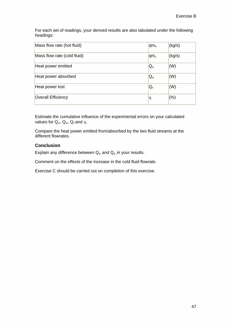
For each set of readings, your derived results are also tabulated under the following headings:
Mass flow rate (hot fluid) qmh (kg/s)
Mass flow rate (cold fluid) qmc (kg/s)
Heat power emitted Qe (W)
Heat power absorbed Qa (W)
Heat power lost Qf (W)
Overall Efficiency (%)
Estimate the cumulative influence of the experimental errors on your calculated values for Qe, Qa, Qf and .
Compare the heat power emitted from/absorbed by the two fluid streams at the different flowrates.
Conclusion
Explain any difference between Qe and Qa in your results.
Comment on the effects of the increase in the cold fluid flowrate.
Exercise C should be carried out on completion of this exercise.
47

48
Exercise C: Cocurrent and Countercurrent Flow
Objective
To demonstrate the differences between cocurrent flow (hot and cold flows in same direction) and countercurrent flow (hot and cold flows in the opposite direction) and the effect on the heat transferred, temperature efficiencies and temperature profiles through a Tubular Heat Exchanger.
Method
By measuring the temperatures of the two fluid streams. Using the temperature changes and differences, to calculate the heat energy transferred and the temperature efficiencies.
Equipment Required
HT30XC Computer Compatible Heat Exchanger Service Unit
HT36 Extended Tubular Heat Exchanger
PC running MicrosoftTM Windows 98 or XP with available USB port
Equipment set-up
Before proceeding with the exercise, ensure that the equipment has been prepared as follows:
Locate the HT36 Extended Tubular Heat Exchanger on the HT30XC Service Unit and secure it using the knurled fixings.
Connect the ten thermocouples on the heat exchanger to the appropriate sockets on the front of the HT30XC plinth (labelled T1 – T10).
Connect the hot and cold water supplies as follows:
Ensure that a cold water supply is connected to the inlet of the pressure regulating valve.
Ensure that the service unit is connected to an electrical supply.

Exercise C
Switch on the front Mains switch.
Ensure that the service unit is connected to a suitable PC, and run the HT36 software. Select the Countercurrent exercise.
Switch the service unit from Standby to On by selecting the Power On switch on the mimic diagram screen.
Prime the hot and cold water circuits as described in the Operation section.
Open the cold water flow control valve to give a 4 tube configuration (turn the black valve handle in line with the tube/valve body).
Close the other three manual valves on the accessory configuration (turn the black valve handles at right angles to the tube/valve body).
Theory/Background
Countercurrent operation
When the heat exchanger is operated with countercurrent flow, the hot and cold fluid streams flow in opposite directions across the heat transfer surface (the two fluid streams enter the heat exchanger at opposite ends).
49

Armfield Instruction Manual
From the previous exercises:
Reduction in hot fluid temperature = T1 – T5 (°C)
Increase in cold fluid temperature = T10 – T6 (°C)
Heat power emitted from hot fluid Qe = qmh.Cph (T1 – T5) (W)
A useful measure of the heat exchanger performance is the temperature efficiency of each fluid stream. The temperature change in each fluid stream is compared with the maximum temperature difference between the two fluid streams giving a comparison with an exchanger of infinite size.
Temperature efficiency for hot fluid (%)
Temperature efficiency for cold fluid (%)
Mean Temperature Efficiency (%)
Cocurrent operation
When the heat exchanger is connected for cocurrent operation the hot and cold fluid streams flow in the same direction across the heat transfer surface (the two fluid streams enter the heat exchanger at the same end).
50

Exercise C
Reduction in hot fluid temperature = T5 – T1 (°C)
Increase in cold fluid temperature = T10 – T6 (°C)
Heat power emitted from hot fluid Qe = qmh.Cph (T5 – T1)(W)
Temperature efficiency for hot fluid (%)
Temperature efficiency for cold fluid (%)
Mean Temperature Efficiency (%)
Procedure
(Refer to the Operation section if you need details of the instrumentation and how to operate it.)
In the software, in the ‘Number of Tubes’ box on the left, select ‘4’.
Set a cold water flow rate of 1 l/min by adjusting the arrows on the side of the cold water flow rate display box.
Check the cold water inlet temperature T10 (shown in a display box on the mimic diagram screen).
51

Armfield Instruction Manual
Set the temperature controller to a set point approximately 30oC above the cold water inlet temperature (e.g. if T10 is 15°C then choose a Set Point of 45°C):
Click on the Heater control box. In the heater controller window, type in the required value for the Set Point, and then select Automatic control from the selection on the top right of the window. Check that the Proportional Band is set to 5, the Integral Time to 200 and the Derivative Time to 0, and change them accordingly if they do not match these values. Click on ‘Apply’ and then ‘OK’ to close the window.
Set the hot water flow controller to give 2 l/min: click on the ‘Flow’ controller box, and type the required Set Point (2.0 l/min) into the Set Point box. The Proportional Band should be 100% and the Integral time should be 3s. The Derivative time should be 0s. Select ‘Automatic’ in the top right of the controller window, then ‘Apply’. Select ‘OK’ to close the controller window.
Allow the heat exchanger to stabilise (monitor the temperatures on the mimic diagram display).
When the temperatures are stable select the icon on the top toolbar to record the following:
T1, T2, T3, T4, T5, T6, T7, T8, T9, T10, Fhot, Fcold.
Open the heater controller window and adjust the controller from ‘Automatic’ to ‘Off’. Open the hot water pump controller window and change the set point to 0 l/min. Set the cold water flow control valve to 0%.
Save your results sheet by selecting ‘Save’ from the ‘File’ menu of the software. Save it with a file name such as ‘HT36 Exercise C Countercurrent’.
If a printer is available then you may find it useful to print a graph of the hot and cold water temperatures against the distance from the hot water inlet (the default graph
for the software). To print a graph, select the graph icon ( ), then the print icon.
Select ‘Load New Experiment’ from the ‘File’ menu, and select the Cocurrent exercise.
In the ‘Number of Tubes’ box on the left, select ‘4’.
Set a cold water flow rate of 1 l/min, a hot water flow rate of 2 l/min, and the same hot water temperature set point as for the countercurrent part of this exercise.
When the temperatures are stable select the icon on the top toolbar to record the following:
T1, T2, T3, T4, T5, T6, T7, T8, T9, T10, Fhot, Fcold.
Print a graph of the cocurrent results, and save your results sheet with a title such as ‘HT36 Exercise C Cocurrent’.
If time permits, the exercise may be repeated with 3, 2 and 1 heat exchanger tubes by adjusting the manual flow valves (as described in the Operation section). Remember to select the correct number of tubes within the software to match the valve configuration on the hardware.
52

Exercise C
Results and Calculations
For each set of readings your raw data is presented in a table using the following headings:
Hot fluid volume flowrate qvhot (m3/s) From Fhot (l/min)
Hot fluid inlet temperature T1 (°C) (T5 Cocurrent)
Hot fluid intermediate temperature 1 T2 (°C) (T4 Cocurrent)
Hot fluid intermediate temperature 2 T3 (°C)
Hot fluid intermediate temperature 3 T4 (°C) (T2 Cocurrent)
Hot fluid outlet temperature T5 (°C) (T1 Cocurrent)
Cold fluid volume flowrate qvcold (m3/s) From Fcold (l/min)
Cold fluid inlet temperature T6 (°C)
Cold fluid intermediate temperature 1 T7 (°C)
Cold fluid intermediate temperature 2 T8 (°C)
Cold fluid intermediate temperature 3 T9 (°C)
Cold fluid outlet temperature T10 (°C)
Note: In cocurrent flow T1 is the hot fluid outlet temperature and T5 is the hot fluid inlet temperature.
You should also estimate the experimental errors for these measurements.
For each set of readings plot the temperatures at inlet, mid positions and outlet against position then estimate the profile of each stream through the exchanger.
For each set of readings, the software obtains the following variables. These may also be obtained from the Reference Tables:
Specific heat of hot fluid Cph kJ/kgoK (From table 1 using average temperature)
Density of hot fluid h kg/m3 (From table 2 using average temperature)
For each set of readings your derived results are also tabulated; the following headings are used:
Reduction in hot fluid temperature (oC)
53
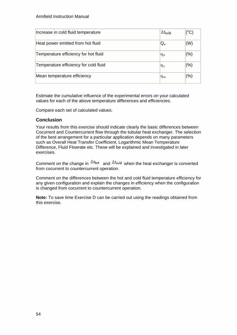
Armfield Instruction Manual
Increase in cold fluid temperature (oC)
Heat power emitted from hot fluid Qe (W)
Temperature efficiency for hot fluid h (%)
Temperature efficiency for cold fluid c (%)
Mean temperature efficiency m (%)
Estimate the cumulative influence of the experimental errors on your calculated values for each of the above temperature differences and efficiencies.
Compare each set of calculated values.
Conclusion
Your results from this exercise should indicate clearly the basic differences between Cocurrent and Countercurrent flow through the tubular heat exchanger. The selection of the best arrangement for a particular application depends on many parameters such as Overall Heat Transfer Coefficient, Logarithmic Mean Temperature Difference, Fluid Flowrate etc. These will be explained and investigated in later exercises.
Comment on the change in and when the heat exchanger is converted from cocurrent to countercurrent operation.
Comment on the differences between the hot and cold fluid temperature efficiency for any given configuration and explain the changes in efficiency when the configuration is changed from cocurrent to countercurrent operation.
Note: To save time Exercise D can be carried out using the readings obtained from this exercise.
54
55
Exercise D: Overall Heat Transfer Coefficient
Objective
To determine the Overall Heat Transfer Coefficient for a Tubular Heat Exchanger using the Logarithmic Mean Temperature Difference to perform the calculations (for cocurrent and countercurrent flow).
Method
By measuring the temperatures of the two fluid streams and calculating the LMTD from which the overall heat transfer coefficient can be calculated for each flow configuration.
Equipment Required
As Exercise C.
Optional Equipment
As Exercise C
Equipment set-up
If using the results from Exercise C then the equipment is not required.
If previous results are not available refer to the Set-up and Procedure sections of Exercise C.
Theory/Background
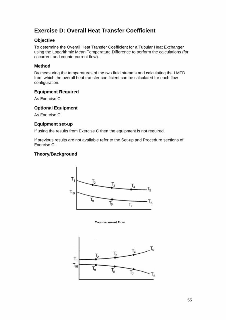
Countercurrent Flow

Armfield Instruction Manual
Cocurrent Flow
Heat power emitted from hot fluid Qe = qmh.Cph (T1 – T5) (W)
Note: To eliminate the effect of heat losses/gains in the cold water stream the heat emitted from the hot fluid stream will be used in the calculations.
Because the temperature difference between the hot and cold fluid streams varies along the length of the heat exchanger it is necessary to derive an average temperature difference (driving force) from which heat transfer calculations can be performed. This average temperature difference is called the Logarithmic Mean
Temperature Difference (LMTD) .
LMTD where
= (T1 – T10)
= (T5 – T6) (oC)
Note: This equation cannot produce a result for the case where = .
LMTD (oC)
In this example the equation for LMTD is the same for both countercurrent and cocurrent operation because the temperature measurement points are fixed on the exchanger. Two different equations will result if the temperature points are related to fluid inlets and outlets.
The heat transmission area in the exchanger must be calculated using the arithmetic mean diameter of the inner tube.
Arithmetic mean diameter (m)
Heat transmission length L (m)
Heat transmission area A = . dm . L (m2)
(dm can be used since r2/r1<1.5 otherwise the logarithmic mean radius dlm must be used)
Overall Heat Transfer Coefficient (W/m2K)
Procedure
Use the results obtained from Exercise C.
56

Exercise D
Results and Calculations
Technical data:
Inner tube inside diameter di = 0.0083 (m)
Inner tube outside diameter do = 0.0095 (m)
Heat transmission length L = 0.330 per tube(1.32 total) (m)
Your raw data is presented in a table using the following headings:
Hot fluid volume flowrate qvhot (m3/s) From Fhot (l/min)
Hot fluid inlet temperature T1 (°C) (T5 Cocurrent)
Hot fluid intermediate temperature 1 T2 (°C) (T4 Cocurrent)
Hot fluid intermediate temperature 2 T3 (°C)
Hot fluid intermediate temperature 3 T4 (°C) (T2 Cocurrent)
Hot fluid outlet temperature T5 (°C) (T1 Cocurrent)
Cold fluid volume flowrate qvcold (m3/s) From Fhot (l/min)
Cold fluid inlet temperature T6 (°C)
Cold fluid intermediate temperature 1 T7 (°C)
Cold fluid intermediate temperature 2 T8 (°C)
Cold fluid intermediate temperature 3 T9 (°C)
Cold fluid outlet temperature T10 (°C)
Arithmetic mean diameter dm (m)
Heat transmission area A (m2)
Note: In cocurrent flow T1 is the hot fluid outlet temperature and T5 is the hot fluid inlet temperature.
You should estimate the experimental errors for these measurements.
For each set of readings, the software calculates the following variables. These may also be obtained from the Reference Tables:
Specific heat of hot fluid Cph kJ/kg°K (From table 1 using average temperature)
57

Armfield Instruction Manual
Density of hot fluid h kg/m3 (From table 2 using average temperature)
For each set of readings, your derived results are tabulated; the following headings are used:
Temperature difference (oC)
Temperature difference (oC)
Mass flow rate (hot fluid) qmh (kg/s)
Heat power emitted from hot fluid Qe (W)
LMTD (°C)
Overall heat transfer coefficient U (W/m2K)
Estimate the cumulative influence of the experimental errors on your calculated
values for and U.
Compare your calculated values for and U for each set of readings.
Conclusion
You have now been introduced to the method for calculating the Overall Heat Transfer Coefficient for a heat exchanger. This is the most important characteristic of a heat exchanger. The effect of fluid flowrates and temperature differences between the hot and cold fluid streams will be investigated in later exercises.
Comment on the differences in and when the heat exchanger is configured
for cocurrent and countercurrent flow. Comment on the resulting values for and its effect on U.
Comment on any difference between the Overall Heat Transfer Coefficient for the same heat exchanger in cocurrent and countercurrent flow (with all other variables the same).
If you have conducted a similar exercise using a plate heat exchanger (HT32) or shell and tube heat exchanger (HT33) compare the performances and comment on the differences.
Exercise E should be carried out on completion of this exercise.
58

59
Exercise E: Effect of Flow Rate
Objective
To investigate the effect of changes in hot and cold fluid flow rate on the Temperature Efficiencies and Overall Heat Transfer Coefficient.
Method
By measuring the fluid temperatures at different combinations of hot and cold fluid flowrate then calculating the corresponding Overall Heat Transfer Coefficient.
Equipment Required
HT30XC Computer Compatible Heat Exchanger Service Unit
HT36 Extended Tubular Heat Exchanger
PC running MicrosoftTM Windows 98 or XP with available USB port
Equipment set-up
Before proceeding with the exercise, ensure that the equipment has been prepared as follows:
Locate the HT36 Extended Tubular Heat Exchanger on the HT30XC Service Unit and secure it using the knurled fixings.
Connect the ten thermocouples on the heat exchanger to the appropriate sockets on the front of the HT30XC plinth (labelled T1 – T10).
Connect the hot and cold water supplies as follows:
Ensure that a cold water supply is connected to the inlet of the pressure regulating valve.
Ensure that the service unit is connected to an electrical supply.
Switch on the front Mains switch.
Ensure that the service unit is connected to a suitable PC, and run the HT36 software. Select the Countercurrent exercise.

Armfield Instruction Manual
Switch the service unit from Standby to On by selecting the Power On switch on the mimic diagram screen.
Prime the hot and cold water circuits as described in the Operation section.
Open the cold water flow control valve to give a 4 tube configuration (turn the black valve handle in line with the tube/valve body).
Close the other three manual valves on the accessory configuration (turn the black valve handles at right angles to the tube/valve body).
Theory/Background
Refer to Teaching Exercises C & D for details of the relevant theory relating to the calculation of the Temperature efficiencies and Overall Heat Transfer Coefficients.
Procedure
(Refer to the Operation section if you need details of the instrumentation and how to operate it.)
In the software, in the ‘Number of Tubes’ box on the left, select ‘4’.
Set a cold water flow rate of 1 l/min by adjusting the arrows on the side of the cold water flow rate display box.
Check the cold water inlet temperature T10 (shown in a display box on the mimic diagram screen).
Set the temperature controller to a set point approximately 30oC above the cold water inlet temperature (e.g. if T10 is 15°C then choose a Set Point of 45°C):
Click on the Heater control box. In the heater controller window, type in the required value for the Set Point, and then select Automatic control from the selection on the top right of the window. Check that the Proportional Band is set to 5, the Integral Time to 200 and the Derivative Time to 0, and change them accordingly if they do not match these values. Click on ‘Apply’ and then ‘OK’ to close the window.
Set the hot water flow controller to give 1 l/min: click on the ‘Flow’ controller box, and type the required Set Point (1.0 l/min) into the Set Point box. The Proportional Band should be 100% and the Integral time should be 3s. The Derivative time should be 0s. Select ‘Automatic’ in the top right of the controller window, then ‘Apply’. Select ‘OK’ to close the controller window.
60

Exercise E
Allow the heat exchanger to stabilise (monitor the temperatures on the mimic diagram display).
When the temperatures are stable select the icon on the top toolbar to record the following:
T1, T2, T3, T4, T5, T6, T7, T8, T9, T10, Fhot, Fcold.
Select the icon to create a new results sheet.
Repeat the above for different settings of the hot and cold fluid volume flowrate as follows. Remember to create a new results sheet for each set of results, and to check that the software is still configured for the correct number of heat exchanger tubes.
Fhot (litres/min) Fcold (litres/min)
2 1
3 1
2 2
1 2
1 3
Note: The above results are all obtained with turbulent flow through the heat exchanger (Reynolds number >2000). If time permits, the effect of laminar flow can be investigated by operating the heat exchanger with flowrates below 0.4 litres/min.
As the flow measurement will not be as accurate at these settings it is suggested that the volume flowrate is checked using a measuring cylinder and stopwatch (to intercept the flow to drain).
Open the heater controller window and adjust the controller from ‘Automatic’ to ‘Off’. Open the hot water pump controller window and change the set point to 0 l/min. Set the cold water flow control valve to 0%.
Save your results sheet by selecting ‘Save’ from the ‘File’ menu of the software. Save it with a file name such as ‘HT36 Exercise E Countercurrent’.
If a printer is available then you may find it useful to print a graph of the hot and cold water temperatures against the distance from the hot water inlet for each set of
results. To print a graph, select the graph icon ( ), then the graph configuration
icon ( ). Highlight the results on the right and move them all to the left using the red arrow key. Select the first set of results (run 1 hot and cold), and move them back onto the y-axis plot with the arrow key. ‘Apply’ and close the print configuration window, then select the print icon. Repeat this process for each set of results.
Select ‘Load New Experiment’ from the ‘File’ menu, and select the Cocurrent exercise.
61

Armfield Instruction Manual
In the ‘Number of Tubes’ box on the left, select ‘4’.
Set a cold water flow rate of 1 l/min, a hot water flow rate of 1 l/min, and the same hot water temperature set point as for the countercurrent part of this exercise.
When the temperatures are stable select the icon on the top toolbar to record the following:
T1, T2, T3, T4, T5, T6, T7, T8, T9, T10, Fhot, Fcold.
Select the icon to create a new results sheet.
Repeat the above for different settings of the hot and cold fluid volume flowrate as follows. Remember to create a new results sheet for each set of results and to check that the software is still configured for the correct number of tubes.
Fhot (litres/min) Fcold (litres/min)
2 1
3 1
2 2
1 2
1 3
Note: The above results are all obtained with turbulent flow through the heat exchanger (Reynolds number >2000). If time permits, the effect of laminar flow can be investigated by operating the heat exchanger with flowrates below 0.4 litres/min.
As the flow measurement will not be as accurate at these settings it is suggested that the volume flowrate is checked using a measuring cylinder and stopwatch (to intercept the flow to drain).
Open the heater controller window and adjust the controller from ‘Automatic’ to ‘Off’. Open the hot water pump controller window and change the set point to 0 l/min. Set the cold water flow control valve to 0%. Set the HT30XC service unit back to Standby by selecting the Power On switch on the mimic diagram.
Save your results sheet by selecting ‘Save’ from the ‘File’ menu of the software. Save it with a file name such as ‘HT36 Exercise E Cocurrent’.
Print your results as for the countercurrent section of this experiment.
If time permits, the exercise may be repeated with 3, 2 and 1 heat exchanger tubes by adjusting the manual flow valves (as described in the Operation section). Remember to select the correct number of tubes to match the configuration of the valves on the hardware.
62

Exercise E
Results and Calculations
Technical data:
Inner tube inside diameter di = 0.0083 (m)
Inner tube outside diameter do = 0.0095 (m)
Heat transmission length L = 0.330 per tube (1.32 total) (m)
For each set of readings your raw data is presented in a table using the following headings:
Hot fluid volume flowrate qvhot (m3/s) From Fhot (l/min)
Hot fluid inlet temperature T1 (°C) (T5 in cocurrent)
Hot fluid intermediate temperature 1 T2 (°C) (T4 in cocurrent)
Hot fluid intermediate temperature 2 T3 (°C)
Hot fluid intermediate temperature 3 T4 (°C) (T2 in cocurrent)
Hot fluid outlet temperature T5 (°C) (T1 in cocurrent)
Cold fluid volume flowrate qvcold (m3/s) From Fcold (l/min)
Cold fluid inlet temperature T6 (°C)
Cold fluid intermediate temperature 1 T7 (°C)
Cold fluid intermediate temperature 2 T8 (°C)
Cold fluid intermediate temperature 3 T9 (°C)
Cold fluid outlet temperature T10 (°C)
Note: In cocurrent flow T1 is the hot fluid outlet temperature and T5 is the hot fluid inlet temperature.
You should estimate the experimental errors for these measurements.
For each set of readings, the software calculates the following variables. These may also be obtained from the Reference Tables:
Specific heat of hot fluid
Cph kJ/kg°K (From table 1 using T2 as the average temperature)
Density of hot fluid h kg/m3 (From table 2 using T2 as the average
63

Armfield Instruction Manual
temperature)
For each set of readings your derived results are also tabulated; the following headings are used:
Mass flow rate (hot fluid) Qmh (kg/s)
Heat power emitted from hot fluid Qe (W)
LMTD (°C)
Overall Heat Transfer Coefficient U (W/m2°C)
Temperature efficiency for hot fluid h (%)
Temperature efficiency for cold fluid c (%)
Mean temperature efficiency m (%)
Estimate the cumulative influence of the experimental errors on your calculated
values for , U and the temperature efficiencies.
Compare the results for U and the temperature efficiencies at the different hot and cold fluid flowrates.
Conclusion
Your results from this exercise should indicate clearly the different effects of hot and cold flowrate on the Overall Heat Transfer Coefficient and temperature efficiencies.
Comment on the effects of changing the hot and cold fluid flowrates.
If additional results were obtained at very low cold fluid flowrate, comment on the effect of laminar flow through the annulus.
If additional results for 1, 2 and 3 tubes were obtained, compare the results for differing lengths of heat exchanger.
If you have conducted a similar exercise using a plate heat exchanger (HT32) or shell and tube heat exchanger (HT33) compare the performances and comment on the differences.
Exercise F should be carried out on completion of this exercise.
64

65
Exercise F: Driving Force
Objective
To investigate the effect of driving force with cocurrent and countercurrent flow.
Method
By measuring the fluid temperatures at different hot fluid inlet temperatures then calculating the corresponding Temperature Efficiencies and Overall Heat Transfer Coefficients to determine the effect of the driving force.
Equipment Required
HT30XC Computer Compatible Heat Exchanger Service Unit
HT36 Extended Tubular Heat Exchanger
PC running MicrosoftTM Windows 98 or XP with available USB port
Equipment set-up
Before proceeding with the exercise, ensure that the equipment has been prepared as follows:
Locate the HT36 Extended Tubular Heat Exchanger on the HT30XC Service Unit and secure it using the knurled fixings.
Connect the ten thermocouples on the heat exchanger to the appropriate sockets on the front of the HT30XC plinth (labelled T1 – T10).
Connect the hot and cold water supplies as follows:
Ensure that a cold water supply is connected to the inlet of the pressure regulating valve.
Ensure that the service unit is connected to an electrical supply.
Switch on the front Mains switch.
Ensure that the service unit is connected to a suitable PC, and run the HT36 software. Select the Countercurrent exercise.

Armfield Instruction Manual
Switch the service unit from Standby to On by selecting the Power On switch on the mimic diagram screen.
Prime the hot and cold water circuits as described in the Operation section.
Open the cold water flow control valve to give a 4 tube configuration (turn the black valve handle in line with the tube/valve body).
Close the other three manual valves on the accessory configuration (turn the black valve handles at right angles to the tube/valve body).
Theory/Background
Refer to Teaching Exercises C and D for details of the relevant theory relating to the calculation of the Temperature Efficiencies and Overall Heat Transfer Coefficients.
Procedure
(Refer to the Operational section if you need details of the instrumentation and how to operate it.)
In the software, in the ‘Number of Tubes’ box on the left, select ‘4’.
Set a cold water flow rate of 1 l/min by adjusting the arrows on the side of the cold water flow rate display box.
Check the cold water inlet temperature T10 (shown in a display box on the mimic diagram screen).
Set the temperature controller to a set point approximately 15oC above the cold water inlet temperature (e.g. if T10 is 15°C then choose a Set Point of 30°C):
Click on the Heater control box. In the heater controller window, type in the required value for the Set Point, and then select Automatic control from the selection on the top right of the window. Check that the Proportional Band is set to 5, the Integral Time to 200 and the Derivative Time to 0, and change them accordingly if they do not match these values. Click on ‘Apply’ and then ‘OK’ to close the window.
Set the hot water flow controller to give 2 l/min: click on the ‘Flow’ controller box, and type the required Set Point (2.0 l/min) into the Set Point box. The Proportional Band should be 100% and the Integral time should be 3s. The Derivative time should be 0s. Select ‘Automatic’ in the top right of the controller window, then ‘Apply’. Select ‘OK’ to close the controller window.
66

Exercise F
Allow the heat exchanger to stabilise (monitor the temperatures on the mimic diagram display).
When the temperatures are stable select the icon on the top toolbar to record the following:
T1, T2, T3, T4, T5, T6, T7, T8, T9, T10, Fhot, Fcold.
Select the icon to create a new results sheet.
Repeat the above at different Set Points for the hot water temperature controller, increasing in steps of 5oC until the limit on the heater/controller is reached (Approximately 50°C depending on the cold fluid inlet temperature).
Open the heater controller window and adjust the controller from ‘Automatic’ to ‘Off’. Open the hot water pump controller window and change the set point to 0 l/min. Set the cold water flow control valve to 0%.
Save your results sheet by selecting ‘Save’ from the ‘File’ menu of the software. Save it with a file name such as ‘HT36 Exercise E Countercurrent’.
If a printer is available then you may find it useful to print a graph of the hot and cold water temperatures against the distance from the hot water inlet for each set of
results. To print a graph, select the graph icon ( ), then the graph configuration
icon ( ). Highlight the results on the right and move them all to the left using the red arrow key. Select the first set of results (run 1 hot and cold), and move them back onto the y-axis plot with the arrow key. ‘Apply’ and close the print configuration window, then select the print icon. Repeat this process for each set of results.
If there is plenty of time then the procedure may be repeated for different flow rates, different hot water Set Point temperatures, and (if available) different cold water inlet flow temperatures. The maximum cold water outlet temperature achievable is limited by the maximum heater power input, and will depend on the combination of fluid flow rates, cold water inlet temperature, and the number of heat exchanger tubes used. With four tubes at maximum cold water flow rate, the maximum temperature gain in the cold fluid may be as low as 5 to 10°C.
Select ‘Load New Experiment’ from the ‘File’ menu, and select the Cocurrent exercise.
In the software, in the ‘Number of Tubes’ box on the left, select ‘4’.
Set a cold water flow rate of 1 l/min, a hot water flow rate of 2 l/min, and the same initial hot water temperature set point as for the countercurrent part of this exercise.
When the temperatures are stable select the icon on the top toolbar to record the following:
T1, T2, T3, T4, T5, T6, T7, T8, T9, T10, Fhot, Fcold.
Repeat the above for different settings of the hot water temperature controller, increasing in steps of 5oC until the limit on the heater controller is reached.
67

Armfield Instruction Manual
If there is plenty of time then the procedure may be repeated for different flow rates, different hot water Set Point temperatures, and (if available) different cold water inlet flow temperatures. Similar but not identical limitations apply to the maximum attainable heat exchange when operating under cocurrent flow. Students may wish to investigate how these limitations compare to those in countercurrent flow.
The exercise can also be repeated with 1, 2, and 3 heat exchanger tubes used. Remember to set the appropriate number of tubes within the software to suit the valve settings on the hardware.
Results and Calculations
Technical data:
Inner tube inside diameter di = 0.0083 (m)
Inner tube outside diameter do = 0.0095 (m)
Heat transmission length L = 0.330 per tube (1.32 total) (m)
For each set of readings your raw data is presented in a table using the following headings:
Hot fluid volume flowrate qvhot (m3/s) From Fhot (l/min)
Hot fluid inlet temperature T1 (°C) (T5 in cocurrent)
Hot fluid intermediate temperature 1 T2 (°C) (T4 in cocurrent)
Hot fluid intermediate temperature 2 T3 (°C)
Hot fluid intermediate temperature 3 T4 (°C) (T2 in cocurrent)
Hot fluid outlet temperature T5 (°C) (T1 in cocurrent)
Cold fluid volume flowrate qvcold (m3/s) From Fcold (l/min)
Cold fluid inlet temperature T6 (°C)
Cold fluid intermediate temperature 1 T7 (°C)
Cold fluid intermediate temperature 2 T8 (°C)
Cold fluid intermediate temperature 3 T9 (°C)
Cold fluid outlet temperature T10 (°C)
Note: In cocurrent flow T1 is the hot fluid outlet temperature and T5 is the hot fluid inlet temperature.
You should also estimate the experimental errors for these measurements.
68

Exercise F
For each set of readings, the software calculates the following variables. These may also be obtained from the Reference Tables:
Specific heat of hot fluid
Cph kJ/kg°K (From table 1 using average hot water temperature)
Density of hot fluid h kg/m3 (From table 2 using T2 average hot water temperature)
For each set of readings your derived results are also tabulated; the following headings are used:
Mass flow rate (hot fluid) Qmh (kg/s)
Heat power emitted from hot fluid Qe (W)
LMTD (°C)
Overall Heat Transfer Coefficient U (W/m2oC)
Temperature efficiency for hot fluid h (%)
Temperature efficiency for cold fluid c (%)
Mean temperature efficiency m (%)
Estimate the cumulative influence of the experimental errors on your calculated
values for , U and the temperature efficiencies.
Compare your derived results at the various differential fluid temperatures.
Conclusion
Your results from this exercise should indicate clearly the effect of driving force (temperature difference between the hot and cold fluid streams) on the Overall Heat Transfer Coefficient and Temperature Efficiencies.
If you have conducted a similar exercise using a plate heat exchanger (HT32) or shell and tube heat exchanger (HT33) compare the performances and comment on the differences.
69

70
Exercise G: Project Work
To Investigate Heat Loss from the Tubular Heat Exchanger
Practical Teaching Exercises A to F are performed with hot water flowing through the inner tube and cold water flowing through the outer annulus. This arrangement minimises the loss of heat from the heat exchanger because the temperature difference between the cold water stream and the ambient air is relatively small. (If the ambient air temperature is higher than the average temperature of the cold water stream then a small gain in heat can occur.)
An investigation of heat loss from the heat exchanger when the hot water flows through the outer annulus would provide a suitable project for students who have completed the previous training exercises. The quick release fittings between the heat exchanger and the service unit will allow the hot and cold fluid streams to be interchanged.
By comparing the heat power emitted from the hot water with the heat power absorbed by the cold water, the heat loss from the exchanger to the surroundings can be determined. Details of the necessary measurements and calculations are given in Teaching Exercise B.
Note: As the outer annulus of the heat exchanger is manufactured using clear acrylic tube, the hot water flowing through the outer annulus should be limited to 65°C to minimise softening of the tube. Similarly, the heat exchanger should not be operated with hot water in the outer annulus for long periods of time.
To Investigate Reduction in Heat Transfer Coefficient due to Fouling of the Heat Transfer Surfaces
The effect of fouling of the heat transfer surfaces can provide an interesting project for students who have completed the previous training exercises.
The construction of the heat exchanger using ‘O’ ring seals allows the inner tubes to be easily removed and replaced with alternative tubes, the inside surface of which the have been pre-fouled.
Metal tubes 9.5mm (3/8”) outside diameter and 380 mm long (not supplied) should be provided for the student to foul by coating the inside diameter with a suitable insulating layer.
Note: The action of pushing the metal tube through an ‘O’ ring prevents the application of fouling to the outer surface of the metal tube.
If alternative tubing is not available then the existing tubes can be fouled but it will be necessary to remove the fouling before using the heat exchanger for normal measurements.
To remove the inner metal tube from the heat exchanger, disconnect the quick release fittings from each end of the tube then pull the tube out of the assembly taking care not to damage the ‘O’ ring seals. Before re-inserting the metal tube, or installing an alternative tube with fouling on the inner surface, lubricate the ‘O’ ring seals with a small amount of wetting agent.
Note: The PVC housing at each end of the acrylic tube is bonded to the acrylic tube and cannot be removed.

Exercise G
Designing an Alternative Heat Exchanger
An interesting project for students who have completed the previous training exercises is to build and test a heat exchanger of their own design. Provided that the alternative heat exchanger is constructed with inlet and outlet connections to suit the quick release fittings on the HT36 Extended Tubular Heat Exchanger, then the fittings used on the HT36 may be transferred directly, complete with the temperature sensors fitted. The alternative heat exchanger can then be connected directly to the HT30XC Service Unit for evaluation.
The inlet and outlet tubes should be 9.5mm (3/8”) outside diameter to allow direct connection to the fittings supplied with the HT36 Extended Tubular Heat Exchanger. If using the temperature sensors only from the HT36 then the tappings for the temperature sensors should be 9.5mm (3/8”) inside diameter.
Teaching Exercises A to F may be applied to the students’; own design of heat exchanger as appropriate.
Typical projects might include:
A tubular heat exchanger constructed with different internal dimensions.
A tubular heat exchanger constructed using different materials.
A tubular heat exchanger incorporating a helical spacer in the outer annulus to increase the local velocity of the cold water relative to the metal tube.
71

72
Contact Details for Further Information
Main Office: Armfield Limited
Bridge House West Street Ringwood Hampshire England BH24 1DY
Tel: +44 (0)1425 478781 Fax: +44 (0)1425 470916 Email: [email protected] [email protected] Web: http://www.armfield.co.uk
US Office: Armfield Inc.
436 West Commodore Blvd (#2) Jackson, NJ 08527
Tel: (732) 928 3332 Fax: (732) 928 3542 Email: [email protected]