Tetra Pak Tubular Heat Exchanger...
4
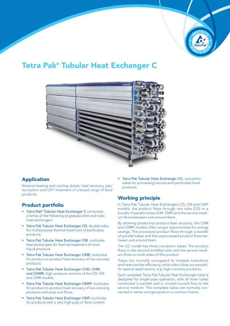
Application General heating and cooling duties, heat recovery, pas- teurization and UHT treatment of a broad range of food products. Product portfolio • Tetra Pak ® Tubular Heat Exchanger C comprises a family of the following singlepass shell-and-tube heat exchangers: • Tetra Pak Tubular Heat Exchanger CD, double tube, for multipurpose thermal treatment of particulate products. • Tetra Pak Tubular Heat Exchanger CM, multitube heat exchangers for thermal treatment of most liquid products. • Tetra Pak Tubular Heat Exchanger CMR, multitube for product-to-product heat recovery of low-viscosity products. • Tetra Pak Tubular Heat Exchanger CHD, CHM and CHMR, high-pressure versions of the CD, CM and CMR models. • Tetra Pak Tubular Heat Exchanger CMRF , multitube for product-to-product heat recovery of low-viscosity products with pulp and fibres. • Tetra Pak Tubular Heat Exchanger CMP , multitube for products with a very high pulp or fibre content. • Tetra Pak Tubular Heat Exchanger CC, concentric tubes for processing viscous and particulate food products. Working principle In Tetra Pak Tubular Heat Exchangers CD, CM and CMP models, the product flows through one tube (CD) or a bundle of parallel tubes (CM, CMP) and the service medi- um flows between and around them. By allowing product-to-product heat recovery, the CMR and CMRF models offer unique opportunities for energy savings. The processed product flows through a bundle of parallel tubes and the unprocessed product flows be- tween and around them. The CC model has three concentric tubes. The product flows in the second (middle) tube and the service medi- um flows on both sides of the product. Tubes are normally corrugated to increase turbulence and heat transfer efficiency, while a few tubes are smooth, for special applications, e.g. high-viscosity products. Each complete Tetra Pak Tubular Heat Exchanger tube is designed for single-pass operation, with all inner tubes connected in parallel and in counter-current flow to the service medium. The complete tubes are normally con- nected in series and grouped on a common frame. Tetra Pak ® Tubular Heat Exchanger C
Transcript of Tetra Pak Tubular Heat Exchanger...
ApplicationGeneral heating and cooling duties, heat recovery, pas-teurization and UHT treatment of a broad range of food products.
Product portfolio• Tetra Pak® Tubular Heat Exchanger C comprises a family of the following singlepass shell-and-tube heat exchangers:
• Tetra Pak Tubular Heat Exchanger CD, double tube, for multipurpose thermal treatment of particulate products.
• Tetra Pak Tubular Heat Exchanger CM, multitube heat exchangers for thermal treatment of most liquid products.
• Tetra Pak Tubular Heat Exchanger CMR, multitube for product-to-product heat recovery of low-viscosity products.
• Tetra Pak Tubular Heat Exchanger CHD, CHM and CHMR, high-pressure versions of the CD, CM and CMR models.
• Tetra Pak Tubular Heat Exchanger CMRF, multitube for product-to-product heat recovery of low-viscosity products with pulp and fibres.
• Tetra Pak Tubular Heat Exchanger CMP, multitube for products with a very high pulp or fibre content.
• Tetra Pak Tubular Heat Exchanger CC, concentric tubes for processing viscous and particulate food products.
Working principleIn Tetra Pak Tubular Heat Exchangers CD, CM and CMP models, the product flows through one tube (CD) or a bundle of parallel tubes (CM, CMP) and the service medi-um flows between and around them.
By allowing product-to-product heat recovery, the CMR and CMRF models offer unique opportunities for energy savings. The processed product flows through a bundle of parallel tubes and the unprocessed product flows be-tween and around them.
The CC model has three concentric tubes. The product flows in the second (middle) tube and the service medi-um flows on both sides of the product.
Tubes are normally corrugated to increase turbulence and heat transfer efficiency, while a few tubes are smooth, for special applications, e.g. high-viscosity products.
Each complete Tetra Pak Tubular Heat Exchanger tube is designed for single-pass operation, with all inner tubes connected in parallel and in counter-current flow to the service medium. The complete tubes are normally con-nected in series and grouped on a common frame.
Tetra Pak® Tubular Heat Exchanger C
OptionsMaterials
• Most tube inserts and bends can be supplied in 1.4547 (254 SMO)
• Shell in grade 1.4404 (AISI 316L)
Insulation
• One or several sections of tubes with carpets of 25 mm mineral wool covered with silicon cloth
Seals
• Product seals in PTFE
Accessories
• Base frame
• Holding tubes, single or double, in lengths adapted to the flow and holding time. Several tubes can be connected in series.
• Protective panels (compulsory for high-temperature and high-pressure applications)
Design
• 3 m tube lengths (except CMRF and CC versions)
Approval
• PED certification or other pressure-vessel codes available for different models
Commissioning
• Kit with tools (for maintenance) and extra seals (for tube inserts and product flanges)
Particulars required for quotationTo assure an accurate quotation on the most suitable unit, order enquiries should include particulars of:
• Required flow rates
• Temperature programme
• Physical properties of product and media
• Desired working pressure
• Maximum acceptable pressure drop
EnvironmentUtility consumption and heat recovery are optimized for each specific case. The exact amount of energy con-sumed depends on the duty the specific heat exchanger performs. In pasteurization duties, it is possible to utilize product-to-product heat recovery, thereby reducing ener-gy consumption considerably. Tetra Pak Tubular Heat Ex-changers consist of parts that can be separated for recy-cling purposes.
Standard designThe heat transfer surface consists of a bundle of straight tubes or three straight concentric tubes welded into tube plates at both ends. The tube plates are sealed from the shell connections by O-rings and the shell connections are sealed from the shell in the same way – creating a system that allows movement between the different parts as well as between individual tubes. The complete tube rests on a cradle which also allows movement. This design – the Floating Protection System – absorbs the effects of ΔT and ensures that the tubes will not crack due to thermal ex-pansion. Moreover, it enables the product tubes to be re-moved from the shell for inspection, for improved food safety, and it allows replacement of individual parts, re-ducing downtime and cost significantly.
Tetra Pak® Tubular Heat Exchangers C are based on a modular concept that simplifies expansion and/or recon-figuration of tube modules. Different tube types and sizes can be mounted on the same frame.
In the special Tetra Pak Tubular Heat Exchanger CMRF model, the inner tubes are spring-loaded, which stretches them and thus eliminates the need for baffles that create problems with fibrous products. This opens the door to product-to-product heat recovery, which means opportu-nities for reduced energy consumption, even with fibrous products (fibre length up to 15 mm).
The standard tube length is 6 metres.
Material
Product-wetted surfaces in pressure-vessel steel, 1.4404 (AISI 316L). Other parts in 1.4307 (AISI 304L). Product seals in EPDM.
Design temperature
Design temperature: 160 °C (320 °F)
Approval
The tubes and shells are designed in accordance with PED (European Pressure Equipment Directive) for the specified temperature and for the pressure ranges shown in the ta-ble on the opposite page. MHLW and CRN available on request.
Key to type designations
CMR 85 / 12 x 16 C - 6 a b c d e f
a Model designation Ex. CMR = Multitube model, regenerative execution
b Outer shell diameter in mm
c Number of product tubes For CC model, N = Normal or W = Wide channel gap
d Outer product tube diameter in mm
e C = corrugated tube S = smooth tube
f Module length in m (3 or 6)
Tetra Pak® Tubular Heat Exchanger C
2 731 2 731
1 0301 450
1 880
1 74
61
326
906
486
270±20
904
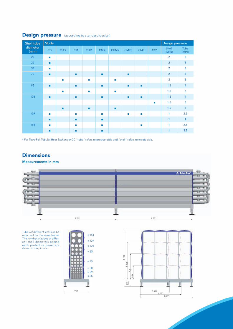
Tubes of different sizes can be mounted on the same frame. The number of tubes of differ-ent shell diameters behind each protective panel are shown in the picture.
⌀ 154
⌀ 129
⌀ 108
⌀ 85
⌀ 70
⌀ 29⌀ 38
⌀ 25
Design pressure (according to standard design)
Shell tube diameter
(mm)
Model Design pressure
CD CHD CM CHM CMR CHMR CMRF CMP CC* Shell (MPa)
Tube (MPa)
25 ■ 2 8
29 ■ 2 8
38 ■ 2 8
70 ■ ■ ■ ■ 2 5
■ ■ ■ 2 8
85 ■ ■ ■ ■ ■ 1.6 4
■ ■ ■ 1.6 6
108 ■ ■ ■ ■ ■ 1.6 4
■ 1.6 5
■ ■ ■ 1.6 6
129 ■ ■ ■ ■ ■ 1 2.5
■ ■ ■ 1 4
154 ■ ■ ■ ■ 1 2.5
■ ■ ■ 1 3.2
* For Tetra Pak Tubular Heat Exchanger CC “tube” refers to product side and “shell” refers to media side.
DimensionsMeasurements in mm
© T
etra
Pak
Inte
rnat
iona
l S.A
., 20
14, 6
3747
, GB
We reserve the rights to introduce design modifications without prior notice. Tetra Pak, and PROTECTS WHAT’S GOOD are trademarks belonging to the Tetra Pak Group.
www.tetrapak.com
Tetra Pak® Tubular Heat Exchanger C
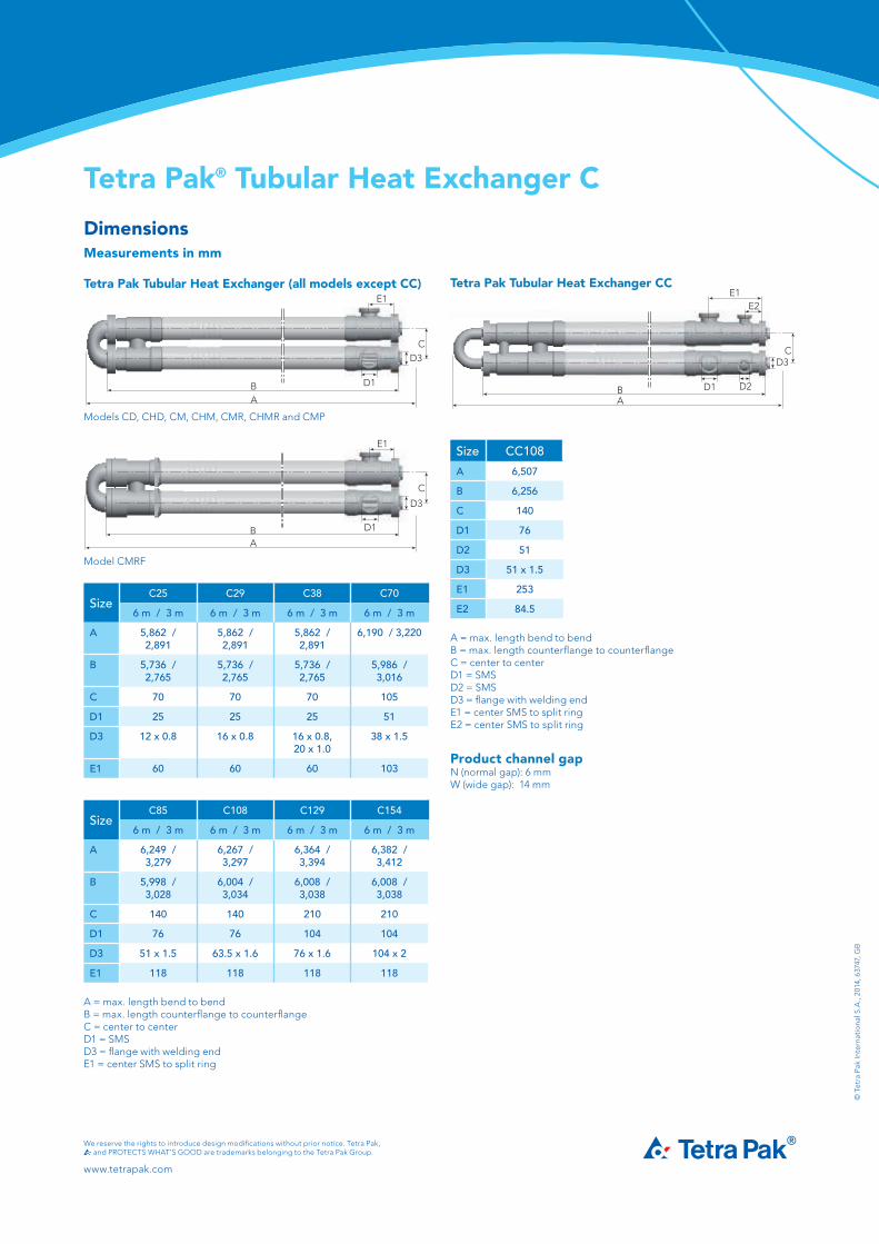
DimensionsMeasurements in mm
Tetra Pak Tubular Heat Exchanger (all models except CC)E1
D3C
B D1
A
Models CD, CHD, CM, CHM, CMR, CHMR and CMP
E1
D3
D1
C
BA
Model CMRF
SizeC25 C29 C38 C70
6 m / 3 m 6 m / 3 m 6 m / 3 m 6 m / 3 m
A 5,862 / 2,891
5,862 / 2,891
5,862 / 2,891
6,190 / 3,220
B 5,736 / 2,765
5,736 / 2,765
5,736 / 2,765
5,986 / 3,016
C 70 70 70 105
D1 25 25 25 51
D3 12 x 0.8 16 x 0.8 16 x 0.8, 20 x 1.0
38 x 1.5
E1 60 60 60 103
SizeC85 C108 C129 C154
6 m / 3 m 6 m / 3 m 6 m / 3 m 6 m / 3 m
A 6,249 / 3,279
6,267 / 3,297
6,364 / 3,394
6,382 / 3,412
B 5,998 / 3,028
6,004 / 3,034
6,008 / 3,038
6,008 / 3,038
C 140 140 210 210
D1 76 76 104 104
D3 51 x 1.5 63.5 x 1.6 76 x 1.6 104 x 2
E1 118 118 118 118
A = max. length bend to bendB = max. length counterflange to counterflangeC = center to centerD1 = SMSD3 = flange with welding endE1 = center SMS to split ring
Tetra Pak Tubular Heat Exchanger CC
Size CC108
A 6,507
B 6,256
C 140
D1 76
D2 51
D3 51 x 1.5
E1 253
E2 84.5
A = max. length bend to bendB = max. length counterflange to counterflangeC = center to centerD1 = SMSD2 = SMSD3 = flange with welding endE1 = center SMS to split ringE2 = center SMS to split ring
Product channel gapN (normal gap): 6 mmW (wide gap): 14 mm
E2E1
D3
D2D1
C
BA