Extended or Composite Systems: Deformation Rotational...
42
Extended or Composite Systems: Deformation Rotational Motion: Rotational Kinematics Lana Sheridan De Anza College Mar 5, 2020
Transcript of Extended or Composite Systems: Deformation Rotational...

Extended or Composite Systems:Deformation
Rotational Motion:Rotational Kinematics
Lana Sheridan
De Anza College
Mar 5, 2020

Last Time
• center of mass tricks and examples
• systems of many particles

Overview
• deforming systems
• rotation
• rotational kinematics
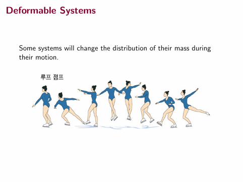
Deformable Systems
Some systems will change the distribution of their mass duringtheir motion.

Deformable Systems
Some systems will change the distribution of their mass duringtheir motion.
1Image from http://northdallasgazette.com

Deformable Systems
In a system that is deformed, the positions of the masses ofparticles may change relative to the center of mass, but we canstill study the system by considering what happens to the center ofmass.
276 Chapter 9 Linear Momentum and Collisions
moving it through a distance x1 as shown in Figure 9.22b. During this time inter-val, the right block moves through a distance x2. At the end of this time interval, the force F is removed.
(A) Find the resulting speed vSCM of the center of mass of the system.
Conceptualize Imagine what happens as you push on the left block. It begins to move to the right in Figure 9.22, and the spring begins to compress. As a result, the spring pushes to the right on the right block, which begins to move to the right. At any given time, the blocks are generally moving with different velocities. As the cen-ter of mass of the system moves to the right with a constant speed after the force is removed, the two blocks oscillate back and forth with respect to the center of mass.
Categorize We apply three analysis models in this problem: the deformable sys-tem of two blocks and a spring is modeled as a nonisolated system in terms of energy because work is being done on it by the applied force. It is also modeled as a noniso-lated system in terms of momentum because of the force acting on the system during a time interval. Because the applied force on the system is constant, the acceleration of its center of mass is constant and the center of mass is modeled as a particle under constant acceleration.
Analyze Using the nonisolated system (momentum) model, we apply the impulse–momentum theorem to the system of two blocks, recognizing that the force F is constant during the time interval Dt while the force is applied.
S O L U T I O N
Write Equation 9.40 for the system: Dpx 5 Ix S 1 2 m 2 1vCM 2 0 2 5 F Dt
(1) 2 mvCM 5 F Dt
During the time interval Dt, the center of mass of the sys-tem moves a distance 12 1x1 1 x2 2 . Use this fact to express the time interval in terms of vCM,avg:
Dt 512 1x1 1 x2 2
vCM,avg
Because the center of mass is modeled as a particle under constant acceleration, the average velocity of the center of mass is the average of the initial velocity, which is zero, and the final velocity vCM:
Dt 512 1x1 1 x2 2
12 1 0 1 vCM 2 5
1x1 1 x2 2vCM
Substitute this expression into Equation (1): 2 mvCM 5 F 1x1 1 x2 2
vCM
Solve for vCM: vCM 5 ÅF 1x1 1 x2 2
2 m
(B) Find the total energy of the system associated with vibration relative to its center of mass after the force F is removed.
Analyze The vibrational energy is all the energy of the system other than the kinetic energy associated with transla-tional motion of the center of mass. To find the vibrational energy, we apply the conservation of energy equation. The kinetic energy of the system can be expressed as K 5 KCM 1 K vib, where K vib is the kinetic energy of the blocks relative to the center of mass due to their vibration. The potential energy of the system is Uvib, which is the potential energy stored in the spring when the separation of the blocks is some value other than L.
S O L U T I O N
From the nonisolated system (energy) model, express Equation 8.2 for this system:
(2) DKCM 1 DK vib 1 DUvib 5 W
▸ 9.15 c o n t i n u e d
mm
L
F
x2x1
m m
a
b
Figure 9.22 (Example 9.15) (a) Two blocks of equal mass are connected by a spring. (b) The left block is pushed with a constant force of magnitude F and moves a distance x1 during some time inter-val. During this same time interval, the right block moves through a distance x2.

Deformable Systems Problem, pg 288, #59Below is an overhead view of the initial configuration of two pucksof mass m on frictionless ice. The pucks are tied together with astring of length `, and negligible mass. At time t = 0, a constantforce of magnitude F begins to pull to the right on the centerpoint of the string. At time t, the moving pucks strike each otherand stick together. At this time, the force has moved through adistance d , and the pucks have attained a speed v . (a) What is vin terms of F , d , `, and m? (b) How much of the energytransferred into the system by work done by the force has beentransformed to internal energy?
288 Chapter 9 Linear Momentum and Collisions
pad on the Earth, taking the vehicle’s initial mass as 3.00 3 106 kg.
63. A rocket for use in deep space is to be capable of boosting a total load (payload plus rocket frame and engine) of 3.00 metric tons to a speed of 10 000 m/s. (a) It has an engine and fuel designed to produce an exhaust speed of 2 000 m/s. How much fuel plus oxi-dizer is required? (b) If a different fuel and engine design could give an exhaust speed of 5 000 m/s, what amount of fuel and oxidizer would be required for the same task? (c) Noting that the exhaust speed in part (b) is 2.50 times higher than that in part (a), explain why the required fuel mass is not simply smaller by a factor of 2.50.
64. A rocket has total mass Mi 5 360 kg, including Mf 5 330 kg of fuel and oxidizer. In interstellar space, it starts from rest at the position x 5 0, turns on its engine at time t 5 0, and puts out exhaust with rel-ative speed ve 5 1 500 m/s at the constant rate k 5 2.50 kg/s. The fuel will last for a burn time of Tb 5 Mf /k 5 330 kg/(2.5 kg/s) 5 132 s. (a) Show that dur-ing the burn the velocity of the rocket as a function of time is given by
v 1 t 2 5 2ve lna1 2ktMi
b (b) Make a graph of the velocity of the rocket as a func-
tion of time for times running from 0 to 132 s. (c) Show that the acceleration of the rocket is
a 1 t 2 5kve
Mi 2 kt
(d) Graph the acceleration as a function of time. (e) Show that the position of the rocket is
x 1 t 2 5 ve aMi
k2 tb ln a1 2
ktMi
b 1 vet
(f) Graph the position during the burn as a function of time.
Additional Problems 65. A ball of mass m is thrown straight up into the air with
an initial speed vi. Find the momentum of the ball (a) at its maximum height and (b) halfway to its maximum height.
66. An amateur skater of mass M is trapped in the middle of an ice rink and is unable to return to the side where there is no ice. Every motion she makes causes her to slip on the ice and remain in the same spot. She decides to try to return to safety by throwing her gloves of mass m in the direction opposite the safe side. (a) She throws the gloves as hard as she can, and they leave her hand with a horizontal velocity vSgloves. Explain whether or not she moves. If she does move, calculate her velocity vSgirl relative to the Earth after she throws the gloves. (b) Discuss her motion from the point of view of the forces acting on her.
67. A 3.00-kg steel ball strikes a wall with a speed of 10.0 m/s at an angle of u 5 60.08 with the surface. It bounces off with the same speed and angle (Fig. P9.67). If the
Q/C
S
SQ/C
M
unaffected by air resistance and his center of mass rises by a maximum of 15.0 cm. Model the floor as com-pletely solid and motionless. (a) Does the floor impart impulse to the person? (b) Does the floor do work on the person? (c) With what momentum does the person leave the floor? (d) Does it make sense to say that this momentum came from the floor? Explain. (e) With what kinetic energy does the person leave the floor? (f) Does it make sense to say that this energy came from the floor? Explain.
59. Figure P9.59a shows an overhead view of the initial configuration of two pucks of mass m on frictionless ice. The pucks are tied together with a string of length , and negligible mass. At time t 5 0, a constant force of magnitude F begins to pull to the right on the center point of the string. At time t, the moving pucks strike each other and stick together. At this time, the force has moved through a distance d, and the pucks have attained a speed v (Fig. P9.59b). (a) What is v in terms of F, d, ,, and m? (b) How much of the energy trans-ferred into the system by work done by the force has been transformed to internal energy?
,
m
m
v
dF F
dCM
t ! 0 t ! t
a b
Figure P9.59
Section 9.9 Rocket Propulsion 60. A model rocket engine has an average thrust of 5.26 N.
It has an initial mass of 25.5 g, which includes fuel mass of 12.7 g. The duration of its burn is 1.90 s. (a) What is the average exhaust speed of the engine? (b) This engine is placed in a rocket body of mass 53.5 g. What is the final velocity of the rocket if it were to be fired from rest in outer space by an astronaut on a space-walk? Assume the fuel burns at a constant rate.
61. A garden hose is held as shown in Figure P9.61. The hose is originally full of motionless water. What additional force is necessary to hold the nozzle stationary after the water flow is turned on if the discharge rate is 0.600 kg/s with a speed of 25.0 m/s?
62. Review. The first stage of a Saturn V space vehicle con-sumed fuel and oxidizer at the rate of 1.50 3 104 kg/s with an exhaust speed of 2.60 3 103 m/s. (a) Calculate the thrust produced by this engine. (b) Find the accel-eration the vehicle had just as it lifted off the launch
S
Figure P9.61

Deformable Systems
(a) Speed of pucks, v , after collision?
F = M aCM
F is constant ⇒ aCM is constant.
aCM =F
2m
v2f = v2i + 2aCM∆xCM
v2f = 0 + 2
(F
2m
)(d −
`
2
)vf =
√2Fd − F `
2m

Deformable Systems
(a) Speed of pucks, v , after collision?
F = M aCM
F is constant ⇒ aCM is constant.
aCM =F
2m
v2f = v2i + 2aCM∆xCM
v2f = 0 + 2
(F
2m
)(d −
`
2
)vf =
√2Fd − F `
2m

Deformable Systems
(a) Speed of pucks, v , after collision?
F = M aCM
F is constant ⇒ aCM is constant.
aCM =F
2m
v2f = v2i + 2aCM∆xCM
v2f = 0 + 2
(F
2m
)(d −
`
2
)vf =
√2Fd − F `
2m

Deformable Systems
(b) Increase in internal energy?
system: pucks + pucks’ and ice’s internal degrees of freedom
W = ∆K + ∆Eint
∆Eint = W − Kf
= Fd −1
2(2m)v2
= Fd −1
2(2m)
2Fd − F `
2m
= Fd − Fd + F`
2
=1
2F `

Deformable Systems
(b) Increase in internal energy?
system: pucks + pucks’ and ice’s internal degrees of freedom
W = ∆K + ∆Eint
∆Eint = W − Kf
= Fd −1
2(2m)v2
= Fd −1
2(2m)
2Fd − F `
2m
= Fd − Fd + F`
2
=1
2F `

Rotation of Rigid Objects
Now we understand that while we can treat a collection of particlesas a single point particle at the center of mass, we do not have todo that.
This will allow us to describe another important kind of motion:rotation.
Begin with rotational kinematics.
Rotation of Rigid Objects
Now we understand that while we can treat a collection of particlesas a single point particle at the center of mass, we do not have todo that.
This will allow us to describe another important kind of motion:rotation.
Begin with rotational kinematics.

Rotation of Rigid Objects
To begin, consider a rotating disc.
294 Chapter 10 Rotation of a Rigid Object About a Fixed Axis
defining kinematic variables: position, velocity, and acceleration. We do the same here for rotational motion. Figure 10.1 illustrates an overhead view of a rotating compact disc, or CD. The disc rotates about a fixed axis perpendicular to the plane of the figure and passing through the center of the disc at O. A small element of the disc modeled as a par-ticle at P is at a fixed distance r from the origin and rotates about it in a circle of radius r. (In fact, every element of the disc undergoes circular motion about O.) It is convenient to represent the position of P with its polar coordinates (r, u), where r is the distance from the origin to P and u is measured counterclockwise from some refer-ence line fixed in space as shown in Figure 10.1a. In this representation, the angle u changes in time while r remains constant. As the particle moves along the cir-cle from the reference line, which is at angle u 5 0, it moves through an arc of length s as in Figure 10.1b. The arc length s is related to the angle u through the relationship
s 5 r u (10.1a)
u 5sr (10.1b)
Because u is the ratio of an arc length and the radius of the circle, it is a pure num-ber. Usually, however, we give u the artificial unit radian (rad), where one radian is the angle subtended by an arc length equal to the radius of the arc. Because the cir-cumference of a circle is 2pr, it follows from Equation 10.1b that 3608 corresponds to an angle of (2pr/r) rad 5 2p rad. Hence, 1 rad 5 3608/2p < 57.38. To convert an angle in degrees to an angle in radians, we use that p rad 5 1808, so
u 1rad 2 5p
1808 u 1deg 2
For example, 608 equals p/3 rad and 458 equals p/4 rad. Because the disc in Figure 10.1 is a rigid object, as the particle moves through an angle u from the reference line, every other particle on the object rotates through the same angle u. Therefore, we can associate the angle u with the entire rigid object as well as with an individual particle, which allows us to define the angular position of a rigid object in its rotational motion. We choose a reference line on the object, such as a line connecting O and a chosen particle on the object. The angular position of the rigid object is the angle u between this reference line on the object and the fixed reference line in space, which is often chosen as the x axis. Such identification is similar to the way we define the position of an object in trans-lational motion as the distance x between the object and the reference position, which is the origin, x 5 0. Therefore, the angle u plays the same role in rotational motion that the position x does in translational motion. As the particle in question on our rigid object travels from position ! to posi-tion " in a time interval Dt as in Figure 10.2, the reference line fixed to the object sweeps out an angle Du 5 uf 2 ui. This quantity Du is defined as the angular dis-placement of the rigid object:
Du ; uf 2 ui
The rate at which this angular displacement occurs can vary. If the rigid object spins rapidly, this displacement can occur in a short time interval. If it rotates slowly, this displacement occurs in a longer time interval. These different rotation rates can be quantified by defining the average angular speed vavg (Greek letter omega) as the ratio of the angular displacement of a rigid object to the time inter-val Dt during which the displacement occurs:
vavg ;uf 2 ui
tf 2 ti5
Du
Dt (10.2)Average angular speed X
Referenceline
O Pr
O
P
Referenceline
r su
To define angular position for the disc, a fixed reference line is chosen. A particle at P is located at a distance r from the rotation axis through O.
As the disc rotates, a particle at P moves through an arc length s on a circular path of radius r. The angular position of P is u.
a
b
Figure 10.1 A compact disc rotating about a fixed axis through O perpendicular to the plane of the figure.
Pitfall Prevention 10.1Remember the Radian In rota-tional equations, you must use angles expressed in radians. Don’t fall into the trap of using angles measured in degrees in rotational equations.
x
y
", t f
!, tir
i
O
fu
u
Figure 10.2 A particle on a rotat-ing rigid object moves from ! to " along the arc of a circle. In the time interval Dt 5 tf 2 ti , the radial line of length r moves through an angular displacement Du 5 uf 2 ui.
s = rθ ; θ =s
r
r is constant in time for a rigid object.
Units for θ: radians. Often written as “rad”. But notice, that adimensional analysis gives [m]
[m] = 1, unitless! The radian is anartificial unit. In fact, angles given in radians are dimensionless.

Rotation of Rigid Objects
How does the angle advance in time?
294 Chapter 10 Rotation of a Rigid Object About a Fixed Axis
defining kinematic variables: position, velocity, and acceleration. We do the same here for rotational motion. Figure 10.1 illustrates an overhead view of a rotating compact disc, or CD. The disc rotates about a fixed axis perpendicular to the plane of the figure and passing through the center of the disc at O. A small element of the disc modeled as a par-ticle at P is at a fixed distance r from the origin and rotates about it in a circle of radius r. (In fact, every element of the disc undergoes circular motion about O.) It is convenient to represent the position of P with its polar coordinates (r, u), where r is the distance from the origin to P and u is measured counterclockwise from some refer-ence line fixed in space as shown in Figure 10.1a. In this representation, the angle u changes in time while r remains constant. As the particle moves along the cir-cle from the reference line, which is at angle u 5 0, it moves through an arc of length s as in Figure 10.1b. The arc length s is related to the angle u through the relationship
s 5 r u (10.1a)
u 5sr (10.1b)
Because u is the ratio of an arc length and the radius of the circle, it is a pure num-ber. Usually, however, we give u the artificial unit radian (rad), where one radian is the angle subtended by an arc length equal to the radius of the arc. Because the cir-cumference of a circle is 2pr, it follows from Equation 10.1b that 3608 corresponds to an angle of (2pr/r) rad 5 2p rad. Hence, 1 rad 5 3608/2p < 57.38. To convert an angle in degrees to an angle in radians, we use that p rad 5 1808, so
u 1rad 2 5p
1808 u 1deg 2
For example, 608 equals p/3 rad and 458 equals p/4 rad. Because the disc in Figure 10.1 is a rigid object, as the particle moves through an angle u from the reference line, every other particle on the object rotates through the same angle u. Therefore, we can associate the angle u with the entire rigid object as well as with an individual particle, which allows us to define the angular position of a rigid object in its rotational motion. We choose a reference line on the object, such as a line connecting O and a chosen particle on the object. The angular position of the rigid object is the angle u between this reference line on the object and the fixed reference line in space, which is often chosen as the x axis. Such identification is similar to the way we define the position of an object in trans-lational motion as the distance x between the object and the reference position, which is the origin, x 5 0. Therefore, the angle u plays the same role in rotational motion that the position x does in translational motion. As the particle in question on our rigid object travels from position ! to posi-tion " in a time interval Dt as in Figure 10.2, the reference line fixed to the object sweeps out an angle Du 5 uf 2 ui. This quantity Du is defined as the angular dis-placement of the rigid object:
Du ; uf 2 ui
The rate at which this angular displacement occurs can vary. If the rigid object spins rapidly, this displacement can occur in a short time interval. If it rotates slowly, this displacement occurs in a longer time interval. These different rotation rates can be quantified by defining the average angular speed vavg (Greek letter omega) as the ratio of the angular displacement of a rigid object to the time inter-val Dt during which the displacement occurs:
vavg ;uf 2 ui
tf 2 ti5
Du
Dt (10.2)Average angular speed X
Referenceline
O Pr
O
P
Referenceline
r su
To define angular position for the disc, a fixed reference line is chosen. A particle at P is located at a distance r from the rotation axis through O.
As the disc rotates, a particle at P moves through an arc length s on a circular path of radius r. The angular position of P is u.
a
b
Figure 10.1 A compact disc rotating about a fixed axis through O perpendicular to the plane of the figure.
Pitfall Prevention 10.1Remember the Radian In rota-tional equations, you must use angles expressed in radians. Don’t fall into the trap of using angles measured in degrees in rotational equations.
x
y
", t f
!, tir
i
O
fu
u
Figure 10.2 A particle on a rotat-ing rigid object moves from ! to " along the arc of a circle. In the time interval Dt 5 tf 2 ti , the radial line of length r moves through an angular displacement Du 5 uf 2 ui.
∆θ = θf − θi

Angular Speed
Rate at which the angle advances is a speed: the angular speed, ω.
Average angular speed:
ωavg =θf − θitf − ti
=∆θ
∆t
Instantaneous angular speed:
ω =dθ
dt

Angular Acceleration
Rate at which the angular speed changes: the angular acceleration,α.
Average angular acceleration:
αavg =ωf −ωi
tf − ti=∆ω
∆t
Instantaneous angular acceleration:
α =dω
dt

Rotation of Rigid Objects and Vector Quantities
We can also define these quantities as vectors! (Provided we fixthe axis of rotation.)
This might seem a bit strange because the direction of the motionany point (other than the axis) on a rotating disc is alwayschanging.
However, the angle can be positive or negative depending onwhether it is clockwise or counterclockwise from the referencepoint.
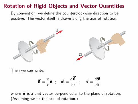
Rotation of Rigid Objects and Vector QuantitiesBy convention, we define the counterclockwise direction to bepositive. The vector itself is drawn along the axis of rotation.296 Chapter 10 Rotation of a Rigid Object About a Fixed Axis
direction of vS for the particle is out of the plane of the diagram when the rotation is counterclockwise and into the plane of the diagram when the rotation is clock-wise. To illustrate this convention, it is convenient to use the right-hand rule demon-strated in Figure 10.3. When the four fingers of the right hand are wrapped in the direction of rotation, the extended right thumb points in the direction of vS . The direction of aS follows from its definition aS ; dvS /dt. It is in the same direction as vS if the angular speed is increasing in time, and it is antiparallel to vS if the angular speed is decreasing in time.
10.2 Analysis Model: Rigid Object Under Constant Angular Acceleration
In our study of translational motion, after introducing the kinematic variables, we considered the special case of a particle under constant acceleration. We follow the same procedure here for a rigid object under constant angular acceleration. Imagine a rigid object such as the CD in Figure 10.1 rotates about a fixed axis and has a constant angular acceleration. In parallel with our analysis model of the particle under constant acceleration, we generate a new analysis model for rota-tional motion called the rigid object under constant angular acceleration. We develop kinematic relationships for this model in this section. Writing Equation 10.5 in the form dv 5 a dt and integrating from ti 5 0 to tf 5 t gives
vf 5 vi 1 at (for constant a) (10.6)
where vi is the angular speed of the rigid object at time t 5 0. Equation 10.6 allows us to find the angular speed vf of the object at any later time t. Substituting Equa-tion 10.6 into Equation 10.3 and integrating once more, we obtain
uf 5 ui 1 vit 1 12at 2 1 for constant a 2 (10.7)
where ui is the angular position of the rigid object at time t 5 0. Equation 10.7 allows us to find the angular position uf of the object at any later time t. Eliminating t from Equations 10.6 and 10.7 gives
vf2 5 vi
2 1 2a(uf 2 ui) (for constant a) (10.8)
This equation allows us to find the angular speed vf of the rigid object for any value of its angular position uf . If we eliminate a between Equations 10.6 and 10.7, we obtain
uf 5 ui 1 12 1vi 1 vf 2 t 1 for constant a 2 (10.9)
Notice that these kinematic expressions for the rigid object under constant angu-lar acceleration are of the same mathematical form as those for a particle under constant acceleration (Chapter 2). They can be generated from the equations for translational motion by making the substitutions x S u, v S v, and a S a. Table 10.1 compares the kinematic equations for the rigid object under constant angular acceleration and particle under constant acceleration models.
Q uick Quiz 10.2 Consider again the pairs of angular positions for the rigid object in Quick Quiz 10.1. If the object starts from rest at the initial angular position, moves counterclockwise with constant angular acceleration, and arrives at the final angular position with the same angular speed in all three cases, for which choice is the angular acceleration the highest?
Rotational kinematic X equations
vS
vS
Figure 10.3 The right-hand rule for determining the direction of the angular velocity vector.
Pitfall Prevention 10.3Just Like Translation? Equations 10.6 to 10.9 and Table 10.1 might suggest that rotational kinematics is just like translational kinemat-ics. That is almost true, with two key differences. (1) In rotational kinematics, you must specify a rotation axis (per Pitfall Pre-vention 10.2). (2) In rotational motion, the object keeps return-ing to its original orientation; therefore, you may be asked for the number of revolutions made by a rigid object. This concept has no analog in translational motion.
Table 10.1 Kinematic Equations for Rotational and Translational MotionRigid Object Under Constant Angular Acceleration Particle Under Constant Acceleration vf 5 vi 1 at (10.6) vf 5 vi 1 at (2.13) uf 5 ui 1 vit 1 12at2 (10.7) xf 5 xi 1 vit 1 12at2 (2.16) vf
2 5 vi2 1 2a(uf 2 ui) (10.8) vf
2 5 vi2 1 2a(xf 2 xi) (2.17)
uf 5 ui 1 12(vi 1 vf)t (10.9) xf 5 xi 1 12(vi 1 vf)t (2.15)
296 Chapter 10 Rotation of a Rigid Object About a Fixed Axis
direction of vS for the particle is out of the plane of the diagram when the rotation is counterclockwise and into the plane of the diagram when the rotation is clock-wise. To illustrate this convention, it is convenient to use the right-hand rule demon-strated in Figure 10.3. When the four fingers of the right hand are wrapped in the direction of rotation, the extended right thumb points in the direction of vS . The direction of aS follows from its definition aS ; dvS /dt. It is in the same direction as vS if the angular speed is increasing in time, and it is antiparallel to vS if the angular speed is decreasing in time.
10.2 Analysis Model: Rigid Object Under Constant Angular Acceleration
In our study of translational motion, after introducing the kinematic variables, we considered the special case of a particle under constant acceleration. We follow the same procedure here for a rigid object under constant angular acceleration. Imagine a rigid object such as the CD in Figure 10.1 rotates about a fixed axis and has a constant angular acceleration. In parallel with our analysis model of the particle under constant acceleration, we generate a new analysis model for rota-tional motion called the rigid object under constant angular acceleration. We develop kinematic relationships for this model in this section. Writing Equation 10.5 in the form dv 5 a dt and integrating from ti 5 0 to tf 5 t gives
vf 5 vi 1 at (for constant a) (10.6)
where vi is the angular speed of the rigid object at time t 5 0. Equation 10.6 allows us to find the angular speed vf of the object at any later time t. Substituting Equa-tion 10.6 into Equation 10.3 and integrating once more, we obtain
uf 5 ui 1 vit 1 12at 2 1 for constant a 2 (10.7)
where ui is the angular position of the rigid object at time t 5 0. Equation 10.7 allows us to find the angular position uf of the object at any later time t. Eliminating t from Equations 10.6 and 10.7 gives
vf2 5 vi
2 1 2a(uf 2 ui) (for constant a) (10.8)
This equation allows us to find the angular speed vf of the rigid object for any value of its angular position uf . If we eliminate a between Equations 10.6 and 10.7, we obtain
uf 5 ui 1 12 1vi 1 vf 2 t 1 for constant a 2 (10.9)
Notice that these kinematic expressions for the rigid object under constant angu-lar acceleration are of the same mathematical form as those for a particle under constant acceleration (Chapter 2). They can be generated from the equations for translational motion by making the substitutions x S u, v S v, and a S a. Table 10.1 compares the kinematic equations for the rigid object under constant angular acceleration and particle under constant acceleration models.
Q uick Quiz 10.2 Consider again the pairs of angular positions for the rigid object in Quick Quiz 10.1. If the object starts from rest at the initial angular position, moves counterclockwise with constant angular acceleration, and arrives at the final angular position with the same angular speed in all three cases, for which choice is the angular acceleration the highest?
Rotational kinematic X equations
vS
vS
Figure 10.3 The right-hand rule for determining the direction of the angular velocity vector.
Pitfall Prevention 10.3Just Like Translation? Equations 10.6 to 10.9 and Table 10.1 might suggest that rotational kinematics is just like translational kinemat-ics. That is almost true, with two key differences. (1) In rotational kinematics, you must specify a rotation axis (per Pitfall Pre-vention 10.2). (2) In rotational motion, the object keeps return-ing to its original orientation; therefore, you may be asked for the number of revolutions made by a rigid object. This concept has no analog in translational motion.
Table 10.1 Kinematic Equations for Rotational and Translational MotionRigid Object Under Constant Angular Acceleration Particle Under Constant Acceleration vf 5 vi 1 at (10.6) vf 5 vi 1 at (2.13) uf 5 ui 1 vit 1 12at2 (10.7) xf 5 xi 1 vit 1 12at2 (2.16) vf
2 5 vi2 1 2a(uf 2 ui) (10.8) vf
2 5 vi2 1 2a(xf 2 xi) (2.17)
uf 5 ui 1 12(vi 1 vf)t (10.9) xf 5 xi 1 12(vi 1 vf)t (2.15)
Then we can write:
#»
θθθ =s
rn̂ ; #»ωωω =
d#»
θθθ
dt; #»α =
d #»ωωω
dt
where #̂»n is a unit vector perpendicular to the plane of rotation.(Assuming we fix the axis of rotation.)

Comparison of Linear and Rotational quantities
Linear Quantities Rotational Quantities
#»x#»
θ
#»v = d #»xdt
#»ω = d#»
θdt
#»a = d #»vdt
#»α = d # »ωdt

Rotational Kinematics
If α is constant, we have basically the same kinematics equationsas before, but the relations are between the new quantities.
#»ωf = #»ωi +#»αt
#»
θ f =#»
θ i +#»ωi t +
1
2#»αt2
ω2f = ω2
i + 2 #»α · # »
∆θ
#»ωavg =1
2( #»ωi +
#»ωf )
#»
θ f =#»
θ i +1
2( #»ωi +
#»ωf )t
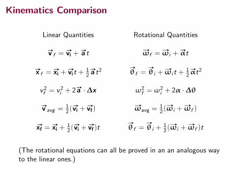
Kinematics Comparison
Linear Quantities Rotational Quantities
#»v f = #»vi +#»a t #»ωf = #»ωi +
#»αt
#»x f = #»xi +#»vit +
12
#»a t2#»
θ f =#»
θ i +#»ωi t +
12
#»αt2
v2f = v2i + 2 #»a ·∆x ω2f = ω2
i + 2α ·∆θ
#»v avg = 12(
#»vi +#»vf)
#»ωavg =12(
#»ωi +#»ωf )
#»xf =#»xi +
12(
#»vi +#»vf)t
#»
θ f =#»
θ i +12(
#»ωi +#»ωf )t
(The rotational equations can all be proved in an an analogous wayto the linear ones.)

Using Rotational Kinematics Equations: Example 1
Page 325, #5
324 Chapter 10 Rotation of a Rigid Object About a Fixed Axis
mine the angular position, angular speed, and angu-lar acceleration of the door (a) at t 5 0 and (b) at t 5 3.00 s.
4. A bar on a hinge starts from rest and rotates with an angular acceleration a 5 10 1 6t, where a is in rad/s2 and t is in seconds. Determine the angle in radians through which the bar turns in the first 4.00 s.
Section 10.2 Analysis Model: Rigid Object Under Constant Angular Acceleration 5. A wheel starts from rest and rotates with constant
angular acceleration to reach an angular speed of 12.0 rad/s in 3.00 s. Find (a) the magnitude of the angu-
W
Section 10.1 Angular Position, Velocity, and Acceleration 1. (a) Find the angular speed of the Earth’s rotation about
its axis. (b) How does this rotation affect the shape of the Earth?
2. A potter’s wheel moves uniformly from rest to an angu-lar speed of 1.00 rev/s in 30.0 s. (a) Find its average angular acceleration in radians per second per second. (b) Would doubling the angular acceleration during the given period have doubled the final angular speed?
3. During a certain time interval, the angular position of a swinging door is described by u 5 5.00 1 10.0t 1 2.00t 2, where u is in radians and t is in seconds. Deter-
Q/C
W
far side and pulled forward horizontally, the tricycle would start to roll forward. (a) Instead, assume a string is attached to the lower pedal on the near side and pulled forward horizontally as shown by A. Will the tri-cycle start to roll? If so, which way? Answer the same questions if (b) the string is pulled forward and upward as shown by B, (c) if the string is pulled straight down as shown by C, and (d) if the string is pulled forward and downward as shown by D. (e) What If? Suppose the string is instead attached to the rim of the front wheel and pulled upward and backward as shown by E. Which way does the tricycle roll? (f) Explain a pattern of reasoning, based on the figure, that makes it easy to answer questions such as these. What physical quantity must you evaluate?
B
A
DC
E
Figure CQ10.15
16. A person balances a meterstick in a horizontal posi-tion on the extended index fingers of her right and left hands. She slowly brings the two fingers together. The stick remains balanced, and the two fingers always meet at the 50-cm mark regardless of their original positions. (Try it!) Explain why that occurs.
11. If you see an object rotating, is there necessarily a net torque acting on it?
12. If a small sphere of mass M were placed at the end of the rod in Figure 10.21, would the result for v be greater than, less than, or equal to the value obtained in Example 10.11?
13. Three objects of uniform density—a solid sphere, a solid cylinder, and a hollow cylinder—are placed at the top of an incline (Fig. CQ10.13). They are all released from rest at the same elevation and roll with-out slipping. (a) Which object reaches the bottom first? (b) Which reaches it last? Note: The result is indepen-dent of the masses and the radii of the objects. (Try this activity at home!)
Figure CQ10.13
14. Which of the entries in Table 10.2 applies to finding the moment of inertia (a) of a long, straight sewer pipe rotating about its axis of symmetry? (b) Of an embroi-dery hoop rotating about an axis through its center and perpendicular to its plane? (c) Of a uniform door turning on its hinges? (d) Of a coin turning about an axis through its center and perpendicular to its faces?
15. Figure CQ10.15 shows a side view of a child’s tricycle with rubber tires on a horizontal concrete sidewalk. If a string were attached to the upper pedal on the
Problems
The problems found in this
chapter may be assigned online in Enhanced WebAssign
1. straightforward; 2. intermediate; 3. challenging
1. full solution available in the Student Solutions Manual/Study Guide
AMT Analysis Model tutorial available in Enhanced WebAssign
GP Guided Problem
M Master It tutorial available in Enhanced WebAssign
W Watch It video solution available in Enhanced WebAssign
BIO
Q/C
S
Problems 325
lar acceleration of the wheel and (b) the angle in radi-ans through which it rotates in this time interval.
6. A centrifuge in a medical laboratory rotates at an angu-lar speed of 3 600 rev/min. When switched off, it rotates through 50.0 revolutions before coming to rest. Find the constant angular acceleration of the centrifuge.
7. An electric motor rotating a workshop grinding wheel at 1.00 3 102 rev/min is switched off. Assume the wheel has a constant negative angular acceleration of magni-tude 2.00 rad/s2. (a) How long does it take the grinding wheel to stop? (b) Through how many radians has the wheel turned during the time interval found in part (a)?
8. A machine part rotates at an angular speed of 0.060 rad/s; its speed is then increased to 2.2 rad/s at an angular acceleration of 0.70 rad/s2. (a) Find the angle through which the part rotates before reaching this final speed. (b) If both the initial and final angu-lar speeds are doubled and the angular acceleration remains the same, by what factor is the angular dis-placement changed? Why?
9. A dentist’s drill starts from rest. After 3.20 s of con-stant angular acceleration, it turns at a rate of 2.51 3 104 rev/min. (a) Find the drill’s angular acceleration. (b) Determine the angle (in radians) through which the drill rotates during this period.
10. Why is the following situation impossible? Starting from rest, a disk rotates around a fixed axis through an angle of 50.0 rad in a time interval of 10.0 s. The angular acceleration of the disk is constant during the entire motion, and its final angular speed is 8.00 rad/s.
11. A rotating wheel requires 3.00 s to rotate through 37.0 revolutions. Its angular speed at the end of the 3.00-s interval is 98.0 rad/s. What is the constant angu-lar acceleration of the wheel?
12. The tub of a washer goes into its spin cycle, starting from rest and gaining angular speed steadily for 8.00 s, at which time it is turning at 5.00 rev/s. At this point, the person doing the laundry opens the lid, and a safety switch turns off the washer. The tub smoothly slows to rest in 12.0 s. Through how many revolutions does the tub turn while it is in motion?
13. A spinning wheel is slowed down by a brake, giving it a constant angular acceleration of 25.60 rad/s2. Dur-ing a 4.20-s time interval, the wheel rotates through 62.4 rad. What is the angular speed of the wheel at the end of the 4.20-s interval?
14. Review. Consider a tall building located on the Earth’s equator. As the Earth rotates, a person on the top floor of the building moves faster than someone on the ground with respect to an inertial reference frame because the person on the ground is closer to the Earth’s axis. Con-sequently, if an object is dropped from the top floor to the ground a distance h below, it lands east of the point vertically below where it was dropped. (a) How far to the east will the object land? Express your answer in terms of h, g, and the angular speed v of the Earth. Ignore air resistance and assume the free-fall acceleration is con-stant over this range of heights. (b) Evaluate the east-ward displacement for h 5 50.0 m. (c) In your judgment,
M
Q/C
MAMT
W
Q/CS
were we justified in ignoring this aspect of the Coriolis effect in our previous study of free fall? (d) Suppose the angular speed of the Earth were to decrease due to tidal friction with constant angular acceleration. Would the eastward displacement of the dropped object increase or decrease compared with that in part (b)?
Section 10.3 Angular and Translational Quantities 15. A racing car travels on a circular track of radius 250 m.
Assuming the car moves with a constant speed of 45.0 m/s, find (a) its angular speed and (b) the magni-tude and direction of its acceleration.
16. Make an order-of-magnitude estimate of the number of revolutions through which a typical automobile tire turns in one year. State the quantities you measure or estimate and their values.
17. A discus thrower (Fig. P4.33, page 104) accelerates a discus from rest to a speed of 25.0 m/s by whirling it through 1.25 rev. Assume the discus moves on the arc of a circle 1.00 m in radius. (a) Calculate the final angu-lar speed of the discus. (b) Determine the magnitude of the angular acceleration of the discus, assuming it to be constant. (c) Calculate the time interval required for the discus to accelerate from rest to 25.0 m/s.
18. Figure P10.18 shows the drive train of a bicycle that has wheels 67.3 cm in diameter and pedal cranks 17.5 cm long. The cyclist pedals at a steady cadence of 76.0 rev/min. The chain engages with a front sprocket 15.2 cm in diameter and a rear sprocket 7.00 cm in diameter. Calculate (a) the speed of a link of the chain relative to the bicycle frame, (b) the angular speed of the bicycle wheels, and (c) the speed of the bicycle rela-tive to the road. (d) What pieces of data, if any, are not necessary for the calculations?
Chain
Front sprocketPedal crank
Rearsprocket
Figure P10.18
19. A wheel 2.00 m in diameter lies in a vertical plane and rotates about its central axis with a constant angular acceleration of 4.00 rad/s2. The wheel starts at rest at t 5 0, and the radius vector of a certain point P on the rim makes an angle of 57.38 with the horizontal at this time. At t 5 2.00 s, find (a) the angular speed of the wheel and, for point P, (b) the tangential speed, (c) the total acceleration, and (d) the angular position.
20. A car accelerates uniformly from rest and reaches a speed of 22.0 m/s in 9.00 s. Assuming the diameter of a tire is 58.0 cm, (a) find the number of revolutions the tire makes during this motion, assuming that no slip-ping occurs. (b) What is the final angular speed of a tire in revolutions per second?
W
WQ/C
M
W

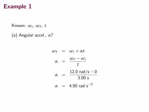
Example 1
Known: ωi , ωf , t
(a) Angular accel., α?
ωf = ωi + αt
α =ωf −ωi
t
α =12.0 rad/s − 0
3.00 s
α = 4.00 rad s−2

Example 1
Known: ωi , ωf , t
(a) Angular accel., α?
ωf = ωi + αt
α =ωf −ωi
t
α =12.0 rad/s − 0
3.00 s
α = 4.00 rad s−2
Example 1
Known: ωi , ωf , t
(a) Angular accel., α?
ωf = ωi + αt
α =ωf −ωi
t
α =12.0 rad/s − 0
3.00 s
α = 4.00 rad s−2

Example 1
Known: ωi , ωf , t, α
(b) Angle in radians, ∆θ?
Either use
∆θ = ωi t +1
2αt2 = 0 +
1
2(4)(3)2 = 18 radians
or use
∆θ =1
2(ωi +ωf )t
∆θ =1
2(0 + 12.0)(3.00)
= 18.0 radians

Example 1
Known: ωi , ωf , t, α
(b) Angle in radians, ∆θ?
Either use
∆θ = ωi t +1
2αt2 = 0 +
1
2(4)(3)2 = 18 radians
or use
∆θ =1
2(ωi +ωf )t
∆θ =1
2(0 + 12.0)(3.00)
= 18.0 radians

Using Rotational Kinematics Equations: Example 2
Page 325, #8
Problems 325
lar acceleration of the wheel and (b) the angle in radi-ans through which it rotates in this time interval.
6. A centrifuge in a medical laboratory rotates at an angu-lar speed of 3 600 rev/min. When switched off, it rotates through 50.0 revolutions before coming to rest. Find the constant angular acceleration of the centrifuge.
7. An electric motor rotating a workshop grinding wheel at 1.00 3 102 rev/min is switched off. Assume the wheel has a constant negative angular acceleration of magni-tude 2.00 rad/s2. (a) How long does it take the grinding wheel to stop? (b) Through how many radians has the wheel turned during the time interval found in part (a)?
8. A machine part rotates at an angular speed of 0.060 rad/s; its speed is then increased to 2.2 rad/s at an angular acceleration of 0.70 rad/s2. (a) Find the angle through which the part rotates before reaching this final speed. (b) If both the initial and final angu-lar speeds are doubled and the angular acceleration remains the same, by what factor is the angular dis-placement changed? Why?
9. A dentist’s drill starts from rest. After 3.20 s of con-stant angular acceleration, it turns at a rate of 2.51 3 104 rev/min. (a) Find the drill’s angular acceleration. (b) Determine the angle (in radians) through which the drill rotates during this period.
10. Why is the following situation impossible? Starting from rest, a disk rotates around a fixed axis through an angle of 50.0 rad in a time interval of 10.0 s. The angular acceleration of the disk is constant during the entire motion, and its final angular speed is 8.00 rad/s.
11. A rotating wheel requires 3.00 s to rotate through 37.0 revolutions. Its angular speed at the end of the 3.00-s interval is 98.0 rad/s. What is the constant angu-lar acceleration of the wheel?
12. The tub of a washer goes into its spin cycle, starting from rest and gaining angular speed steadily for 8.00 s, at which time it is turning at 5.00 rev/s. At this point, the person doing the laundry opens the lid, and a safety switch turns off the washer. The tub smoothly slows to rest in 12.0 s. Through how many revolutions does the tub turn while it is in motion?
13. A spinning wheel is slowed down by a brake, giving it a constant angular acceleration of 25.60 rad/s2. Dur-ing a 4.20-s time interval, the wheel rotates through 62.4 rad. What is the angular speed of the wheel at the end of the 4.20-s interval?
14. Review. Consider a tall building located on the Earth’s equator. As the Earth rotates, a person on the top floor of the building moves faster than someone on the ground with respect to an inertial reference frame because the person on the ground is closer to the Earth’s axis. Con-sequently, if an object is dropped from the top floor to the ground a distance h below, it lands east of the point vertically below where it was dropped. (a) How far to the east will the object land? Express your answer in terms of h, g, and the angular speed v of the Earth. Ignore air resistance and assume the free-fall acceleration is con-stant over this range of heights. (b) Evaluate the east-ward displacement for h 5 50.0 m. (c) In your judgment,
M
Q/C
MAMT
W
Q/CS
were we justified in ignoring this aspect of the Coriolis effect in our previous study of free fall? (d) Suppose the angular speed of the Earth were to decrease due to tidal friction with constant angular acceleration. Would the eastward displacement of the dropped object increase or decrease compared with that in part (b)?
Section 10.3 Angular and Translational Quantities 15. A racing car travels on a circular track of radius 250 m.
Assuming the car moves with a constant speed of 45.0 m/s, find (a) its angular speed and (b) the magni-tude and direction of its acceleration.
16. Make an order-of-magnitude estimate of the number of revolutions through which a typical automobile tire turns in one year. State the quantities you measure or estimate and their values.
17. A discus thrower (Fig. P4.33, page 104) accelerates a discus from rest to a speed of 25.0 m/s by whirling it through 1.25 rev. Assume the discus moves on the arc of a circle 1.00 m in radius. (a) Calculate the final angu-lar speed of the discus. (b) Determine the magnitude of the angular acceleration of the discus, assuming it to be constant. (c) Calculate the time interval required for the discus to accelerate from rest to 25.0 m/s.
18. Figure P10.18 shows the drive train of a bicycle that has wheels 67.3 cm in diameter and pedal cranks 17.5 cm long. The cyclist pedals at a steady cadence of 76.0 rev/min. The chain engages with a front sprocket 15.2 cm in diameter and a rear sprocket 7.00 cm in diameter. Calculate (a) the speed of a link of the chain relative to the bicycle frame, (b) the angular speed of the bicycle wheels, and (c) the speed of the bicycle rela-tive to the road. (d) What pieces of data, if any, are not necessary for the calculations?
Chain
Front sprocketPedal crank
Rearsprocket
Figure P10.18
19. A wheel 2.00 m in diameter lies in a vertical plane and rotates about its central axis with a constant angular acceleration of 4.00 rad/s2. The wheel starts at rest at t 5 0, and the radius vector of a certain point P on the rim makes an angle of 57.38 with the horizontal at this time. At t 5 2.00 s, find (a) the angular speed of the wheel and, for point P, (b) the tangential speed, (c) the total acceleration, and (d) the angular position.
20. A car accelerates uniformly from rest and reaches a speed of 22.0 m/s in 9.00 s. Assuming the diameter of a tire is 58.0 cm, (a) find the number of revolutions the tire makes during this motion, assuming that no slip-ping occurs. (b) What is the final angular speed of a tire in revolutions per second?
W
WQ/C
M
W

Example 2
Known: ωi , ωf , α
(a) ∆θ?
ω2f = ω2
i + 2α∆θ
∆θ =ω2
f −ω2i
2α
=(2.2)2 − (0.060)2
2× 0.70
= 3.5 rad
Example 2
Known: ωi , ωf , α
(a) ∆θ?
ω2f = ω2
i + 2α∆θ
∆θ =ω2
f −ω2i
2α
=(2.2)2 − (0.060)2
2× 0.70
= 3.5 rad

Example 2
Known: ωi , ωf , α
(a) ∆θ?
ω2f = ω2
i + 2α∆θ
∆θ =ω2
f −ω2i
2α
=(2.2)2 − (0.060)2
2× 0.70
= 3.5 rad

Example 2
(b) If both ωi and ωf are doubled, α kept constant, what happensto ∆θ?
∆θ ′ =(2×ωf )
2 − (2×ωi )2
2α
= 4ω2
f −ω2i
2α
= 4∆θ

Relating Rotational Quantities to Translation ofPoints
Consider a point on the rotating object. How does its speed relateto the angular speed?
298 Chapter 10 Rotation of a Rigid Object About a Fixed Axis
10.3 Angular and Translational QuantitiesIn this section, we derive some useful relationships between the angular speed and acceleration of a rotating rigid object and the translational speed and acceleration of a point in the object. To do so, we must keep in mind that when a rigid object rotates about a fixed axis as in Figure 10.4, every particle of the object moves in a circle whose center is on the axis of rotation. Because point P in Figure 10.4 moves in a circle, the translational velocity vector vS is always tangent to the circular path and hence is called tangential velocity. The mag-nitude of the tangential velocity of the point P is by definition the tangential speed v 5 ds/dt, where s is the distance traveled by this point measured along the circular path. Recalling that s 5 r u (Eq. 10.1a) and noting that r is constant, we obtain
v 5dsdt
5 r du
dt
Because d u/dt 5 v (see Eq. 10.3), it follows that
v 5 rv (10.10)
As we saw in Equation 4.17, the tangential speed of a point on a rotating rigid object equals the perpendicular distance of that point from the axis of rotation multiplied by the angular speed. Therefore, although every point on the rigid object has the same angular speed, not every point has the same tangential speed because r is not the same for all points on the object. Equation 10.10 shows that the tangential speed of a point on the rotating object increases as one moves outward from the center of rotation, as we would intuitively expect. For example, the outer end of a swinging golf club moves much faster than a point near the handle. We can relate the angular acceleration of the rotating rigid object to the tangen-tial acceleration of the point P by taking the time derivative of v :
at 5dvdt
5 r dv
dt
at 5 ra (10.11)
That is, the tangential component of the translational acceleration of a point on a rotating rigid object equals the point’s perpendicular distance from the axis of rotation multiplied by the angular acceleration. In Section 4.4, we found that a point moving in a circular path undergoes a radial acceleration ar directed toward the center of rotation and whose magnitude is that of the centripetal acceleration v 2/r (Fig. 10.5). Because v 5 rv for a point
Relation between tangential X velocity and angular velocity
Relation between tangential X acceleration and angular
acceleration
Figure 10.4 As a rigid object rotates about the fixed axis (the z axis) through O, the point P has a tangential velocity vS that is always tangent to the circular path of radius r.
y
P
xO
r su
vS
▸ 10.1 c o n t i n u e d
Answer Notice that these questions are translational analogs to parts (A) and (C) of the original problem. The mathemat-ical solution follows exactly the same form. For the displacement, from the particle under constant acceleration model,
Dx 5 xf 2 xi 5 vit 1 12at 2
5 12.00 m/s 2 12.00 s 2 1 12 13.50 m/s2 2 12.00 s 22 5 11.0 m
and for the velocity,
vf 5 vi 1 at 5 2.00 m/s 1 (3.50 m/s2)(2.00 s) 5 9.00 m/s
There is no translational analog to part (B) because translational motion under constant acceleration is not repetitive.
We know s = rθ, so since the object’s speed is its speed along thepath s,
v =ds
dt= r
dθ
dt

Relating Rotational Quantities to Translation ofPoints
Since ω = dθdt , that gives us and expression for (tangential) speed
v = rω
And differentiating both sides with respect to t again:
at = rα
Notice that the above equation gives the rate of change of speed,which is the tangential acceleration.

Relating Rotational Quantities to Translation ofPoints
Since ω = dθdt , that gives us and expression for (tangential) speed
v = rω
And differentiating both sides with respect to t again:
at = rα
Notice that the above equation gives the rate of change of speed,which is the tangential acceleration.

Centripetal Acceleration
Remember:
at =dv
dt
where v is the speed, not velocity.
So,at = rα
But of course, in order for a mass at that point, radius r , tocontinue moving in a circle, there must be a centripetal componentof acceleration also.
ac =v2
r= ω2r
For a rigid object, the force that supplies this acceleration will besome internal forces between the mass at the rotating point andthe other masses in the object. Those are the forces that hold theobject together.

Summary
• deformations
• rotation
• rotational kinematics
Quiz Friday (tomorrow).
(Uncollected) Homework Serway & Jewett,
• Look at example 9.15 on page 275.
• Ch 9, onward from page 288. Probs: 51, 55, 57, 92
• Ch 10, Probs: 7, 11, 15, 17, 19, 21, 25 (will not be on quiz)