2D Kinematics: Nonuniform Circular Motion Dynamics: Laws...
34
2D Kinematics: Nonuniform Circular Motion Dynamics: Laws of Motion Newton’s 1st & 2nd Laws Lana Sheridan De Anza College Oct 6, 2017
-
Upload
vuongquynh -
Category
Documents
-
view
232 -
download
3
Transcript of 2D Kinematics: Nonuniform Circular Motion Dynamics: Laws...
2D Kinematics: Nonuniform CircularMotion
Dynamics: Laws of MotionNewton’s 1st & 2nd Laws
Lana Sheridan
De Anza College
Oct 6, 2017
Last Time
• relative motion
• uniform circular motion
Overview
• nonuniform circular motion
• Introduce forces
• Newton’s Laws! (1st & 2nd)
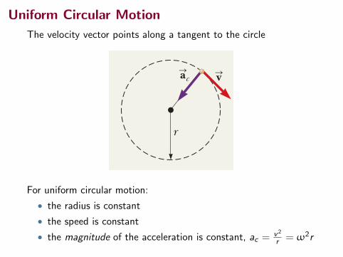
Uniform Circular Motion
The velocity vector points along a tangent to the circle
4.4 Analysis Model: Particle In Uniform Circular Motion 93
continued
Combining this equation with Equation 4.15, we find a relationship between angular speed and the translational speed with which the particle travels in the circular path:
v 5 2pa v2pr
b 5vr S v 5 rv (4.17)
Equation 4.17 demonstrates that, for a fixed angular speed, the translational speed becomes larger as the radial position becomes larger. Therefore, for example, if a merry-go-round rotates at a fixed angular speed v, a rider at an outer position at large r will be traveling through space faster than a rider at an inner position at smaller r. We will investigate Equations 4.16 and 4.17 more deeply in Chapter 10. We can express the centripetal acceleration of a particle in uniform circular motion in terms of angular speed by combining Equations 4.14 and 4.17:
ac 51rv 22
r ac 5 rv2 (4.18)
Equations 4.14–4.18 are to be used when the particle in uniform circular motion model is identified as appropriate for a given situation.
Q uick Quiz 4.4 A particle moves in a circular path of radius r with speed v. It then increases its speed to 2v while traveling along the same circular path. (i) The cen-tripetal acceleration of the particle has changed by what factor? Choose one: (a) 0.25 (b) 0.5 (c) 2 (d) 4 (e) impossible to determine (ii) From the same choices, by what factor has the period of the particle changed?
Analysis Model Particle in Uniform Circular MotionImagine a moving object that can be modeled as a particle. If it moves in a circular path of radius r at a constant speed v, the magnitude of its centripetal acceleration is
ac 5v2
r (4.14)
and the period of the particle’s motion is given by
T 52prv
(4.15)
The angular speed of the particle is
v 52p
T (4.16)
Examples:
of constant length -
fectly circular orbit (Chapter 13)-
form magnetic field (Chapter 29)
nucleus in the Bohr model of the hydrogen atom (Chapter 42)
r
vSacS
Example 4.6 The Centripetal Acceleration of the Earth
(A) What is the centripetal acceleration of the Earth as it moves in its orbit around the Sun?
Conceptualize Think about a mental image of the Earth in a circular orbit around the Sun. We will model the Earth as a particle and approximate the Earth’s orbit as circular (it’s actually slightly elliptical, as we discuss in Chapter 13).
Categorize The Conceptualize step allows us to categorize this problem as one of a particle in uniform circular motion.
Analyze We do not know the orbital speed of the Earth to substitute into Equation 4.14. With the help of Equation 4.15, however, we can recast Equation 4.14 in terms of the period of the Earth’s orbit, which we know is one year, and the radius of the Earth’s orbit around the Sun, which is 1.496 3 1011 m.
AM
S O L U T I O N
Pitfall Prevention 4.5Centripetal Acceleration Is Not Constant We derived the magnitude of the centripetal acceleration vector and found it to be constant for uniform circular motion, but the centripetal accelera-tion vector is not constant. It always points toward the center of the circle, but it continuously changes direction as the object moves around the circular path.
For uniform circular motion:
• the radius is constant
• the speed is constant
• the magnitude of the acceleration is constant, ac = v2
r = ω2r
Non-Uniform Circular Motion
94 Chapter 4 Motion in Two Dimensions
Path ofparticle at
ar
at
ar ataraS
aS
aS !
"
#
Figure 4.16 The motion of a particle along an arbitrary curved path lying in the xy plane. If the velocity vector vS (always tangent to the path) changes in direction and magnitude, the components of the acceleration aS are a tan-gential component at and a radial component ar.
(B) What is the angular speed of the Earth in its orbit around the Sun?
Analyze
S O L U T I O N
Substitute numerical values: ac 54p2 11.496 3 1011 m 211 yr 22 a 1 yr
3.156 3 107 sb2
5 5.93 3 1023 m/s2
Finalize The acceleration in part (A) is much smaller than the free-fall acceleration on the surface of the Earth. An important technique we learned here is replacing the speed v in Equation 4.14 in terms of the period T of the motion. In many problems, it is more likely that T is known rather than v. In part (B), we see that the angular speed of the Earth is very small, which is to be expected because the Earth takes an entire year to go around the circular path once.
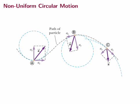
4.5 Tangential and Radial AccelerationLet us consider a more general motion than that presented in Section 4.4. A parti-cle moves to the right along a curved path, and its velocity changes both in direction and in magnitude as described in Figure 4.16. In this situation, the velocity vector is always tangent to the path; the acceleration vector aS, however, is at some angle to the path. At each of three points !, ", and # in Figure 4.16, the dashed blue circles represent the curvature of the actual path at each point. The radius of each circle is equal to the path’s radius of curvature at each point. As the particle moves along the curved path in Figure 4.16, the direction of the total acceleration vector aS changes from point to point. At any instant, this vec-tor can be resolved into two components based on an origin at the center of the dashed circle corresponding to that instant: a radial component ar along the radius of the circle and a tangential component at perpendicular to this radius. The total acceleration vector aS can be written as the vector sum of the component vectors:
aS 5 aSr 1 aSt (4.19)
The tangential acceleration component causes a change in the speed v of the particle. This component is parallel to the instantaneous velocity, and its magnitude is given by
at 5 ` dvdt
` (4.20)
Total acceleration X
Tangential acceleration X
▸ 4.6 c o n t i n u e d
Combine Equations 4.14 and 4.15: ac 5v2
r5
a2prT
b2
r5
4p2rT 2
Substitute numerical values into Equation 4.16: v 52p
1 yr a 1 yr
3.156 3 107 sb 5 1.99 3 1027
s21
Radial and Tangential Accelerations
94 Chapter 4 Motion in Two Dimensions
Path ofparticle at
ar
at
ar ataraS
aS
aS !
"
#
Figure 4.16 The motion of a particle along an arbitrary curved path lying in the xy plane. If the velocity vector vS (always tangent to the path) changes in direction and magnitude, the components of the acceleration aS are a tan-gential component at and a radial component ar.
(B) What is the angular speed of the Earth in its orbit around the Sun?
Analyze
S O L U T I O N
Substitute numerical values: ac 54p2 11.496 3 1011 m 211 yr 22 a 1 yr
3.156 3 107 sb2
5 5.93 3 1023 m/s2
Finalize The acceleration in part (A) is much smaller than the free-fall acceleration on the surface of the Earth. An important technique we learned here is replacing the speed v in Equation 4.14 in terms of the period T of the motion. In many problems, it is more likely that T is known rather than v. In part (B), we see that the angular speed of the Earth is very small, which is to be expected because the Earth takes an entire year to go around the circular path once.
4.5 Tangential and Radial AccelerationLet us consider a more general motion than that presented in Section 4.4. A parti-cle moves to the right along a curved path, and its velocity changes both in direction and in magnitude as described in Figure 4.16. In this situation, the velocity vector is always tangent to the path; the acceleration vector aS, however, is at some angle to the path. At each of three points !, ", and # in Figure 4.16, the dashed blue circles represent the curvature of the actual path at each point. The radius of each circle is equal to the path’s radius of curvature at each point. As the particle moves along the curved path in Figure 4.16, the direction of the total acceleration vector aS changes from point to point. At any instant, this vec-tor can be resolved into two components based on an origin at the center of the dashed circle corresponding to that instant: a radial component ar along the radius of the circle and a tangential component at perpendicular to this radius. The total acceleration vector aS can be written as the vector sum of the component vectors:
aS 5 aSr 1 aSt (4.19)
The tangential acceleration component causes a change in the speed v of the particle. This component is parallel to the instantaneous velocity, and its magnitude is given by
at 5 ` dvdt
` (4.20)
Total acceleration X
Tangential acceleration X
▸ 4.6 c o n t i n u e d
Combine Equations 4.14 and 4.15: ac 5v2
r5
a2prT
b2
r5
4p2rT 2
Substitute numerical values into Equation 4.16: v 52p
1 yr a 1 yr
3.156 3 107 sb 5 1.99 3 1027
s21
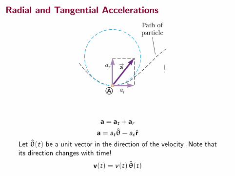
a = at + ar
a = at θ− ac r
Let θ(t) be a unit vector in the direction of the velocity. Note thatits direction changes with time!
v(t) = v(t) θ(t)
Radial and Tangential Accelerations
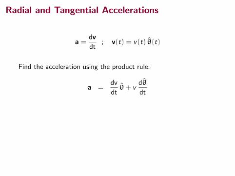
a =dv
dt; v(t) = v(t) θ(t)
Find the acceleration using the product rule:
a =dv
dtθ+ v
dθ
dt
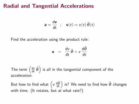
The term(dvdt θ
)is all in the tangential component of the
acceleration.
But how to find what(v dθ
dt
)is? We need to find how θ changes
with time. (It rotates, but at what rate?)
Radial and Tangential Accelerations
a =dv
dt; v(t) = v(t) θ(t)
Find the acceleration using the product rule:
a =dv
dtθ+ v
dθ
dt
The term(dvdt θ
)is all in the tangential component of the
acceleration.
But how to find what(v dθ
dt
)is? We need to find how θ changes
with time. (It rotates, but at what rate?)
Radial and Tangential Accelerations: How do theperpendicular axes change?
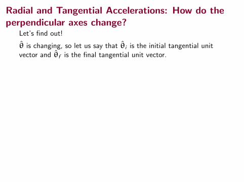
Let’s find out!
θ is changing, so let us say that θi is the initial tangential unitvector and θf is the final tangential unit vector.
Both vectors are 1 unit long (the same length). Both remainperpendicular to the radial direction. Therefore we have twosimilar triangles!
!v!
vf
vi
!r
vivf
ri rf!qu
u
!"S
SS
S S
S
S
S
θ fiθ
ˆ
θ
ˆ
i
θf
Δθ
ˆ
ˆ
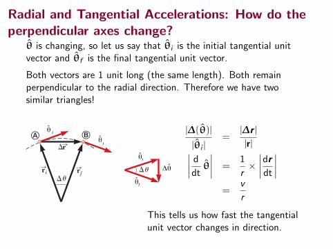
|∆(θ)|
|θi |=
|∆r ||r|∣∣∣∣ d
dtθ
∣∣∣∣ =1
r×
∣∣∣∣drdt
∣∣∣∣=
v
r
This tells us how fast the tangentialunit vector changes in direction.
Radial and Tangential Accelerations: How do theperpendicular axes change?
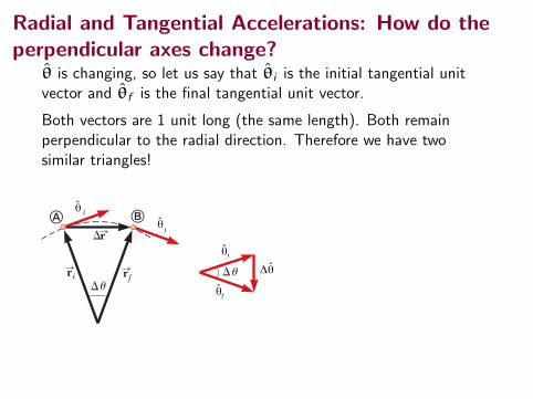
θ is changing, so let us say that θi is the initial tangential unitvector and θf is the final tangential unit vector.
Both vectors are 1 unit long (the same length). Both remainperpendicular to the radial direction. Therefore we have twosimilar triangles!
!v!
vf
vi
!r
vivf
ri rf!qu
u
!"S
SS
S S
S
S
S
θ fiθ
ˆ
θ
ˆ
i
θf
Δθ
ˆ
ˆ
|∆(θ)|
|θi |=
|∆r ||r|∣∣∣∣ d
dtθ
∣∣∣∣ =1
r×
∣∣∣∣drdt
∣∣∣∣=
v
r
This tells us how fast the tangentialunit vector changes in direction.
Radial and Tangential Accelerations: How do theperpendicular axes change?
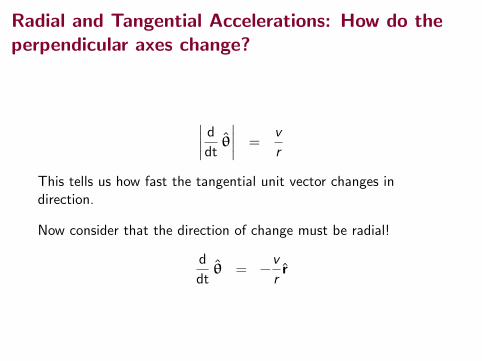
∣∣∣∣ d
dtθ
∣∣∣∣ =v
r
This tells us how fast the tangential unit vector changes indirection.
Now consider that the direction of change must be radial!
d
dtθ = −
v
rr
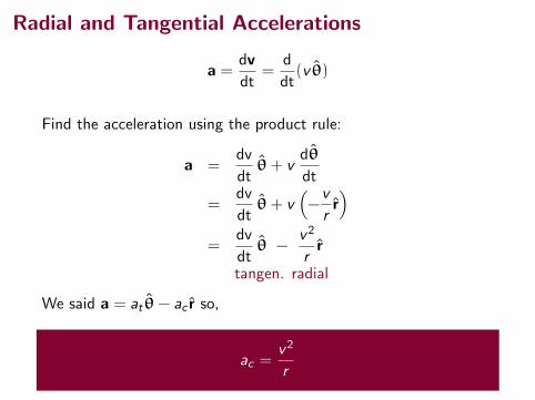
Radial and Tangential Accelerations
a =dv
dt=
d
dt(v θ)
Find the acceleration using the product rule:
a =dv
dtθ+ v
dθ
dt
=dv
dtθ+ v
(−v
rr)
=dv
dtθ −
v2
rr
tangen. radial
We said a = at θ− ac r so,
ac =v2
r
Radial and Tangential Accelerations
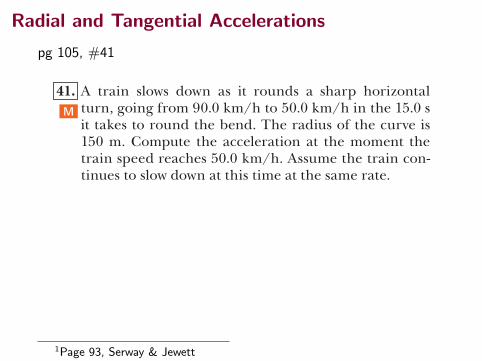
pg 105, #41 Problems 105
41. A train slows down as it rounds a sharp horizontal turn, going from 90.0 km/h to 50.0 km/h in the 15.0 s it takes to round the bend. The radius of the curve is 150 m. Compute the acceleration at the moment the train speed reaches 50.0 km/h. Assume the train con-tinues to slow down at this time at the same rate.
42. A ball swings counterclockwise in a vertical circle at the end of a rope 1.50 m long. When the ball is 36.9° past the lowest point on its way up, its total acceleration is 1222.5 i 1 20.2 j 2 m/s2. For that instant, (a) sketch a vector diagram showing the components of its acceler-ation, (b) determine the magnitude of its radial accel-eration, and (c) determine the speed and velocity of the ball.
43. (a) Can a particle moving with instantaneous speed 3.00 m/s on a path with radius of curvature 2.00 m have an acceleration of magnitude 6.00 m/s2? (b) Can it have an acceleration of magnitude 4.00 m/s2? In each case, if the answer is yes, explain how it can hap-pen; if the answer is no, explain why not.
Section 4.6 Relative Velocity and Relative Acceleration 44. The pilot of an airplane notes that the compass indi-
cates a heading due west. The airplane’s speed relative to the air is 150 km/h. The air is moving in a wind at 30.0 km/h toward the north. Find the velocity of the airplane relative to the ground.
45. An airplane maintains a speed of 630 km/h relative to the air it is flying through as it makes a trip to a city 750 km away to the north. (a) What time interval is required for the trip if the plane flies through a head-wind blowing at 35.0 km/h toward the south? (b) What time interval is required if there is a tailwind with the same speed? (c) What time interval is required if there is a crosswind blowing at 35.0 km/h to the east relative to the ground?
46. A moving beltway at an airport has a speed v1 and a length L. A woman stands on the beltway as it moves from one end to the other, while a man in a hurry to reach his flight walks on the beltway with a speed of v2 relative to the moving beltway. (a) What time inter-val is required for the woman to travel the distance L? (b) What time interval is required for the man to travel this distance? (c) A second beltway is located next to the first one. It is identical to the first one but moves in the opposite direction at speed v1. Just as the man steps onto the beginning of the beltway and begins to walk at speed v2 relative to his beltway, a child steps on the other end of the adjacent beltway. The child stands at rest relative to this second beltway. How long after stepping on the beltway does the man pass the child?
47. A police car traveling at 95.0 km/h is traveling west, chasing a motorist traveling at 80.0 km/h. (a) What is the velocity of the motorist relative to the police car? (b) What is the velocity of the police car relative to the motorist? (c) If they are originally 250 m apart, in what time interval will the police car overtake the motorist?
48. A car travels due east with a speed of 50.0 km/h. Rain-drops are falling at a constant speed vertically with
M
S
M
Suppose a copper sleeve of inner radius 2.10 cm and outer radius 2.20 cm is to be cast. To eliminate bubbles and give high structural integrity, the cen-tripetal acceleration of each bit of metal should be at least 100g. What rate of rotation is required? State the answer in revolutions per minute.
36. A tire 0.500 m in radius rotates at a constant rate of 200 rev/min. Find the speed and acceleration of a small stone lodged in the tread of the tire (on its outer edge).
37. Review. The 20-g centrifuge at NASA’s Ames Research Center in Mountain View, California, is a horizontal, cylindrical tube 58.0 ft long and is represented in Fig-ure P4.37. Assume an astronaut in training sits in a seat at one end, facing the axis of rotation 29.0 ft away. Determine the rotation rate, in revolutions per second, required to give the astronaut a centripetal accelera-tion of 20.0g.
29 ft
Figure P4.37
38. An athlete swings a ball, connected to the end of a chain, in a horizontal circle. The athlete is able to rotate the ball at the rate of 8.00 rev/s when the length of the chain is 0.600 m. When he increases the length to 0.900 m, he is able to rotate the ball only 6.00 rev/s. (a) Which rate of rotation gives the greater speed for the ball? (b) What is the centripetal acceleration of the ball at 8.00 rev/s? (c) What is the centripetal acceleration at 6.00 rev/s?
39. The astronaut orbit-ing the Earth in Figure P4.39 is preparing to dock with a Westar VI satellite. The satellite is in a circular orbit 600 km above the Earth’s surface, where the free-fall accelera-tion is 8.21 m/s2. Take the radius of the Earth as 6 400 km. Determine the speed of the satellite and the time interval required to complete one orbit around the Earth, which is the period of the satellite.
Section 4.5 Tangential and Radial Acceleration 40. Figure P4.40 represents the
total acceleration of a particle moving clockwise in a circle of radius 2.50 m at a certain instant of time. For that instant, find (a) the radial acceleration of the particle, (b) the speed of the particle, and (c) its tangen-tial acceleration.
AMT
Figure P4.39
30.0!
2.50 m
a " 15.0 m/s2
vS
aS
Figure P4.40
W
NAS
A
1Page 93, Serway & Jewett
Forces!
A force is a “push” or a “pull” that an object experiences.
Forces are connected to acceleration of an object that has mass.Unbalanced forces cause an acceleration.
Forces are vectors.
Forces
Two types of forces
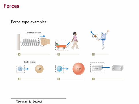
• contact forcesanother object came into contact with the object
• field forcesa kind of interaction between objects without them touchingeach other
Forces
Force type examples:112 Chapter 5 The Laws of Motion
orbit around the Earth. This change in velocity is caused by the gravitational force exerted by the Earth on the Moon. When a coiled spring is pulled, as in Figure 5.1a, the spring stretches. When a stationary cart is pulled, as in Figure 5.1b, the cart moves. When a football is kicked, as in Figure 5.1c, it is both deformed and set in motion. These situations are all examples of a class of forces called contact forces. That is, they involve physical contact between two objects. Other examples of contact forces are the force exerted by gas molecules on the walls of a container and the force exerted by your feet on the floor. Another class of forces, known as field forces, does not involve physical contact between two objects. These forces act through empty space. The gravitational force of attraction between two objects with mass, illustrated in Figure 5.1d, is an example of this class of force. The gravitational force keeps objects bound to the Earth and the planets in orbit around the Sun. Another common field force is the electric force that one electric charge exerts on another (Fig. 5.1e), such as the attractive electric force between an electron and a proton that form a hydrogen atom. A third example of a field force is the force a bar magnet exerts on a piece of iron (Fig. 5.1f). The distinction between contact forces and field forces is not as sharp as you may have been led to believe by the previous discussion. When examined at the atomic level, all the forces we classify as contact forces turn out to be caused by electric (field) forces of the type illustrated in Figure 5.1e. Nevertheless, in developing mod-els for macroscopic phenomena, it is convenient to use both classifications of forces. The only known fundamental forces in nature are all field forces: (1) gravitational forces between objects, (2) electromagnetic forces between electric charges, (3) strong forces between subatomic particles, and (4) weak forces that arise in certain radioac-tive decay processes. In classical physics, we are concerned only with gravitational and electromagnetic forces. We will discuss strong and weak forces in Chapter 46.
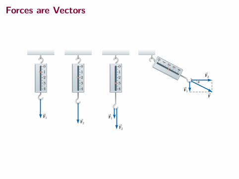
The Vector Nature of ForceIt is possible to use the deformation of a spring to measure force. Suppose a verti-cal force is applied to a spring scale that has a fixed upper end as shown in Fig-ure 5.2a. The spring elongates when the force is applied, and a pointer on the scale reads the extension of the spring. We can calibrate the spring by defining a reference force F
S1 as the force that produces a pointer reading of 1.00 cm. If we
now apply a different downward force FS
2 whose magnitude is twice that of the ref-erence force F
S1 as seen in Figure 5.2b, the pointer moves to 2.00 cm. Figure 5.2c
shows that the combined effect of the two collinear forces is the sum of the effects of the individual forces. Now suppose the two forces are applied simultaneously with F
S1 downward and
FS
2 horizontal as illustrated in Figure 5.2d. In this case, the pointer reads 2.24 cm. The single force F
S that would produce this same reading is the sum of the two vec-
tors FS
1 and FS
2 as described in Figure 5.2d. That is, 0 FS1 0 5 !F12 1 F2
2 5 2.24 units,
b c
M
Field forces
d
!qm "Q
e
Iron N S
f
Contact forces
a
Figure 5.1 Some examples of applied forces. In each case, a force is exerted on the object within the boxed area. Some agent in the environment external to the boxed area exerts a force on the object.
Isaac NewtonEnglish physicist and mathematician (1642–1727)Isaac Newton was one of the most brilliant scientists in history. Before the age of 30, he formulated the basic concepts and laws of mechanics, discovered the law of universal gravita-tion, and invented the mathematical methods of calculus. As a consequence of his theories, Newton was able to explain the motions of the planets, the ebb and flow of the tides, and many special features of the motions of the Moon and the Earth. He also interpreted many fundamental obser-vations concerning the nature of light. His contributions to physical theories dominated scientific thought for two centuries and remain important today.
Brid
gem
an-G
iraud
on/A
rt Re
sour
ce, N
Y
1Serway & Jewett
Diagrams of Forces
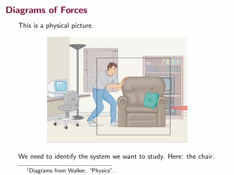
This is a physical picture.
5–3 NEWTON’S SECOND LAW OF MOTION 113
REAL-WORLD PHYSICS: BIO
How walking affects your height
This causes you to grow shorter during the day! Try it. Measure your height firstthing in the morning, then again before going to bed. If you’re like many people,you’ll find that you have shrunk by an inch or so during the day.
Free-Body DiagramsWhen solving problems involving forces and Newton’s laws, it is essential tobegin by making a sketch that indicates each and every external force acting on agiven object. This type of sketch is referred to as a free-body diagram. If we areconcerned only with nonrotational motion, as is the case in this and the next chap-ter, we treat the object of interest as a point particle and apply each of the forces act-ing on the object to that point, as Figure 5–5 shows. Once the forces are drawn, wechoose a coordinate system and resolve each force into components. At this point,Newton’s second law can be applied to each coordinate direction separately.
(a) Sketch the forces
Physical picture
Free-body diagram
(b) Isolate the object of interest (c) Choose a convenient coordinate system (d) Resolve forces into their components
F
W
N
N
FW
N
FW
x
y
O
N
FW
x
y
Fx = F cos θWx = 0
Wy = –W
Nx = 0
Ny = N
Fy =
–F sin θθ
▲ FIGURE 5–5 Constructing and using a free-body diagramThe four basic steps in constructing and using a free-body diagram are illustrated in these sketches. (a) Sketch all of the external forcesacting on an object of interest. Note that only forces acting on the object are shown; none of the forces exerted by the object are included.(b) Isolate the object and treat it as a point particle. (c) Choose a convenient coordinate system. This will often mean aligning a coordi-nate axis to coincide with the direction of one or more forces in the system. (d) Resolve each of the forces into components using thecoordinate system of part (c).
PROBLEM-SOLVING NOTE
External Forces
External forces acting on an object fallinto two main classes: (i) Forces at thepoint of contact with another object, and(ii) forces exerted by an external agent,such as gravity.
WALKMC05_0131536311.QXD 12/8/05 16:43 Page 113
We need to identify the system we want to study. Here: the chair.
1Diagrams from Walker, “Physics”.
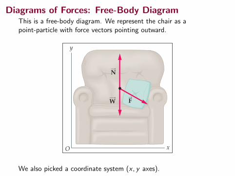
Diagrams of Forces: Free-Body DiagramThis is a free-body diagram. We represent the chair as apoint-particle with force vectors pointing outward.
5–3 NEWTON’S SECOND LAW OF MOTION 113
REAL-WORLD PHYSICS: BIO
How walking affects your height
This causes you to grow shorter during the day! Try it. Measure your height firstthing in the morning, then again before going to bed. If you’re like many people,you’ll find that you have shrunk by an inch or so during the day.
Free-Body DiagramsWhen solving problems involving forces and Newton’s laws, it is essential tobegin by making a sketch that indicates each and every external force acting on agiven object. This type of sketch is referred to as a free-body diagram. If we areconcerned only with nonrotational motion, as is the case in this and the next chap-ter, we treat the object of interest as a point particle and apply each of the forces act-ing on the object to that point, as Figure 5–5 shows. Once the forces are drawn, wechoose a coordinate system and resolve each force into components. At this point,Newton’s second law can be applied to each coordinate direction separately.
(a) Sketch the forces
Physical picture
Free-body diagram
(b) Isolate the object of interest (c) Choose a convenient coordinate system (d) Resolve forces into their components
F
W
N
N
FW
N
FW
x
y
O
N
FW
x
y
Fx = F cos θWx = 0
Wy = –W
Nx = 0
Ny = N
Fy =
–F sin θθ
▲ FIGURE 5–5 Constructing and using a free-body diagramThe four basic steps in constructing and using a free-body diagram are illustrated in these sketches. (a) Sketch all of the external forcesacting on an object of interest. Note that only forces acting on the object are shown; none of the forces exerted by the object are included.(b) Isolate the object and treat it as a point particle. (c) Choose a convenient coordinate system. This will often mean aligning a coordi-nate axis to coincide with the direction of one or more forces in the system. (d) Resolve each of the forces into components using thecoordinate system of part (c).
PROBLEM-SOLVING NOTE
External Forces
External forces acting on an object fallinto two main classes: (i) Forces at thepoint of contact with another object, and(ii) forces exerted by an external agent,such as gravity.
WALKMC05_0131536311.QXD 12/8/05 16:43 Page 113
We also picked a coordinate system (x , y axes).
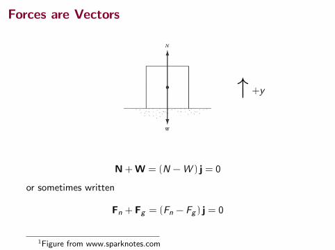
Forces are Vectors
N + W = (N −W ) j = 0
or sometimes written
Fn + Fg = (Fn − Fg ) j = 0
1Figure from www.sparknotes.com
↑ +y
Forces are Vectors
5.2 Newton’s First Law and Inertial Frames 113
and its direction is u 5 tan21 (20.500) 5 226.6°. Because forces have been experi-mentally verified to behave as vectors, you must use the rules of vector addition to obtain the net force on an object.
5.2 Newton’s First Law and Inertial FramesWe begin our study of forces by imagining some physical situations involving a puck on a perfectly level air hockey table (Fig. 5.3). You expect that the puck will remain stationary when it is placed gently at rest on the table. Now imagine your air hockey table is located on a train moving with constant velocity along a perfectly smooth track. If the puck is placed on the table, the puck again remains where it is placed. If the train were to accelerate, however, the puck would start moving along the table opposite the direction of the train’s acceleration, just as a set of papers on your dashboard falls onto the floor of your car when you step on the accelerator. As we saw in Section 4.6, a moving object can be observed from any number of reference frames. Newton’s first law of motion, sometimes called the law of inertia, defines a special set of reference frames called inertial frames. This law can be stated as follows:
If an object does not interact with other objects, it is possible to identify a ref-erence frame in which the object has zero acceleration.
Such a reference frame is called an inertial frame of reference. When the puck is on the air hockey table located on the ground, you are observing it from an inertial reference frame; there are no horizontal interactions of the puck with any other objects, and you observe it to have zero acceleration in that direction. When you are on the train moving at constant velocity, you are also observing the puck from an inertial reference frame. Any reference frame that moves with constant veloc-ity relative to an inertial frame is itself an inertial frame. When you and the train accelerate, however, you are observing the puck from a noninertial reference frame because the train is accelerating relative to the inertial reference frame of the Earth’s surface. While the puck appears to be accelerating according to your obser-vations, a reference frame can be identified in which the puck has zero acceleration.
WW Newton’s first law
WW Inertial frame of reference
01234
A downward force elongates the spring 1.00 cm.
F1S
F1S
F1S
01234
A downward force elongates the spring 2.00 cm.
F2S
F2S
F2S
01234
When and are applied together in the same direction, the spring elongates by 3.00 cm.
F2S
F1S
When is downward and is horizontal, the combination of the two forces elongates the spring by 2.24 cm.
F2S
F1S
a b
01
23
4
F2S
dc
u
F1S
FS
Figure 5.2 The vector nature of a force is tested with a spring scale.
Airflow
Electric blower
Figure 5.3 On an air hockey table, air blown through holes in the surface allows the puck to move almost without friction. If the table is not accelerating, a puck placed on the table will remain at rest.
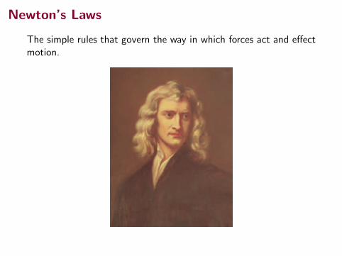
Newton’s Laws
The simple rules that govern the way in which forces act and effectmotion.
112 Chapter 5 The Laws of Motion
orbit around the Earth. This change in velocity is caused by the gravitational force exerted by the Earth on the Moon. When a coiled spring is pulled, as in Figure 5.1a, the spring stretches. When a stationary cart is pulled, as in Figure 5.1b, the cart moves. When a football is kicked, as in Figure 5.1c, it is both deformed and set in motion. These situations are all examples of a class of forces called contact forces. That is, they involve physical contact between two objects. Other examples of contact forces are the force exerted by gas molecules on the walls of a container and the force exerted by your feet on the floor. Another class of forces, known as field forces, does not involve physical contact between two objects. These forces act through empty space. The gravitational force of attraction between two objects with mass, illustrated in Figure 5.1d, is an example of this class of force. The gravitational force keeps objects bound to the Earth and the planets in orbit around the Sun. Another common field force is the electric force that one electric charge exerts on another (Fig. 5.1e), such as the attractive electric force between an electron and a proton that form a hydrogen atom. A third example of a field force is the force a bar magnet exerts on a piece of iron (Fig. 5.1f). The distinction between contact forces and field forces is not as sharp as you may have been led to believe by the previous discussion. When examined at the atomic level, all the forces we classify as contact forces turn out to be caused by electric (field) forces of the type illustrated in Figure 5.1e. Nevertheless, in developing mod-els for macroscopic phenomena, it is convenient to use both classifications of forces. The only known fundamental forces in nature are all field forces: (1) gravitational forces between objects, (2) electromagnetic forces between electric charges, (3) strong forces between subatomic particles, and (4) weak forces that arise in certain radioac-tive decay processes. In classical physics, we are concerned only with gravitational and electromagnetic forces. We will discuss strong and weak forces in Chapter 46.
The Vector Nature of ForceIt is possible to use the deformation of a spring to measure force. Suppose a verti-cal force is applied to a spring scale that has a fixed upper end as shown in Fig-ure 5.2a. The spring elongates when the force is applied, and a pointer on the scale reads the extension of the spring. We can calibrate the spring by defining a reference force F
S1 as the force that produces a pointer reading of 1.00 cm. If we
now apply a different downward force FS
2 whose magnitude is twice that of the ref-erence force F
S1 as seen in Figure 5.2b, the pointer moves to 2.00 cm. Figure 5.2c
shows that the combined effect of the two collinear forces is the sum of the effects of the individual forces. Now suppose the two forces are applied simultaneously with F
S1 downward and
FS
2 horizontal as illustrated in Figure 5.2d. In this case, the pointer reads 2.24 cm. The single force F
S that would produce this same reading is the sum of the two vec-
tors FS
1 and FS
2 as described in Figure 5.2d. That is, 0 FS1 0 5 !F12 1 F2
2 5 2.24 units,
b c
M
Field forces
d
!qm "Q
e
Iron N S
f
Contact forces
a
Figure 5.1 Some examples of applied forces. In each case, a force is exerted on the object within the boxed area. Some agent in the environment external to the boxed area exerts a force on the object.
Isaac NewtonEnglish physicist and mathematician (1642–1727)Isaac Newton was one of the most brilliant scientists in history. Before the age of 30, he formulated the basic concepts and laws of mechanics, discovered the law of universal gravita-tion, and invented the mathematical methods of calculus. As a consequence of his theories, Newton was able to explain the motions of the planets, the ebb and flow of the tides, and many special features of the motions of the Moon and the Earth. He also interpreted many fundamental obser-vations concerning the nature of light. His contributions to physical theories dominated scientific thought for two centuries and remain important today.
Brid
gem
an-G
iraud
on/A
rt Re
sour
ce, N
Y
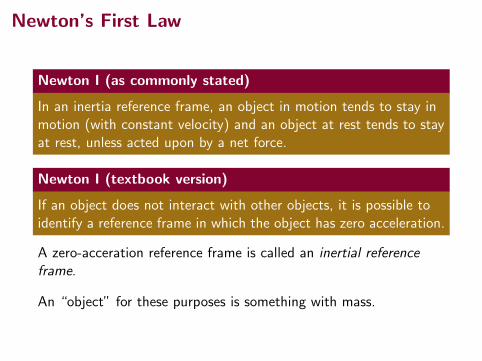
Newton’s First Law
Newton I (as commonly stated)
In an inertia reference frame, an object in motion tends to stay inmotion (with constant velocity) and an object at rest tends to stayat rest, unless acted upon by a net force.
Newton I (textbook version)
If an object does not interact with other objects, it is possible toidentify a reference frame in which the object has zero acceleration.
A zero-acceration reference frame is called an inertial referenceframe.
An “object” for these purposes is something with mass.
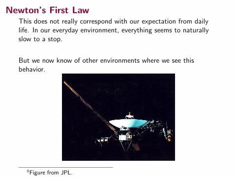
Newton’s First LawThis does not really correspond with our expectation from dailylife. In our everyday environment, everything seems to naturallyslow to a stop.
But we now know of other environments where we see thisbehavior.
0Figure from JPL.
Newton’s First LawThis does not really correspond with our expectation from dailylife. In our everyday environment, everything seems to naturallyslow to a stop.
But we now know of other environments where we see thisbehavior.
0Figure from JPL.
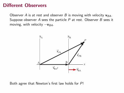
Different Observers
Observer A is at rest and observer B is moving with velocity vBA.Suppose observer A sees the particle P at rest. Observer B sees itmoving, with velocity −vBA.
4.6 Relative Velocity and Relative Acceleration 97
will be separated by a distance vBAt. We label the position P of the particle relative to observer A with the position vector rSP A and that relative to observer B with the position vector rSP B, both at time t. From Figure 4.20, we see that the vectors rSP A and rSP B are related to each other through the expression
rSP A 5 rSP B 1 vSBAt (4.22)
By differentiating Equation 4.22 with respect to time, noting that vSBA is con-stant, we obtain
d rSP A
dt5
d rSP B
dt1 vSBA
uSP A 5 uSP B 1 vSBA (4.23)
where uSPA is the velocity of the particle at P measured by observer A and uSP B is its velocity measured by B. (We use the symbol uS for particle velocity rather than vS, which we have already used for the relative velocity of two reference frames.) Equa-tions 4.22 and 4.23 are known as Galilean transformation equations. They relate the position and velocity of a particle as measured by observers in relative motion. Notice the pattern of the subscripts in Equation 4.23. When relative velocities are added, the inner subscripts (B) are the same and the outer ones (P, A) match the subscripts on the velocity on the left of the equation. Although observers in two frames measure different velocities for the particle, they measure the same acceleration when vSBA is constant. We can verify that by taking the time derivative of Equation 4.23:
d uSP A
dt5
d uSP B
dt1
d vSBA
dt
Because vSBA is constant, d vSBA/dt 5 0. Therefore, we conclude that aSP A 5 aSP B because aSP A 5 d uSP A/dt and aSP B 5 d uSP B/dt. That is, the acceleration of the parti-cle measured by an observer in one frame of reference is the same as that measured by any other observer moving with constant velocity relative to the first frame.
WW Galilean velocity transformation
continued
Example 4.8 A Boat Crossing a River
A boat crossing a wide river moves with a speed of 10.0 km/h relative to the water. The water in the river has a uniform speed of 5.00 km/h due east relative to the Earth.
(A) If the boat heads due north, determine the velocity of the boat relative to an observer standing on either bank.
Conceptualize Imagine moving in a boat across a river while the current pushes you down the river. You will not be able to move directly across the river, but will end up downstream as suggested in Figure 4.21a.
Categorize Because of the combined velocities of you rela-tive to the river and the river relative to the Earth, we can categorize this problem as one involving relative velocities.
Analyze We know vSbr, the velocity of the boat relative to the river, and vSrE, the velocity of the river relative to the Earth. What we must find is vSbE, the velocity of the boat relative to the Earth. The relationship between these three quantities is vSbE 5 vSbr 1 vSrE. The terms in the equation must be manipulated as vector quantities; the vectors are shown in Fig-ure 4.21a. The quantity vSbr is due north; vSrE is due east; and the vector sum of the two, vSbE, is at an angle u as defined in Figure 4.21a.
S O L U T I O N u
br
bE
rE
E
N
S
W
a
vS
vS
vS
E
N
S
W
b
ubr
bE
rEvS
vS
vS
Figure 4.21 (Example 4.8) (a) A boat aims directly across a river and ends up downstream. (b) To move directly across the river, the boat must aim upstream.
SA SB
BA
P
xBAt
BA
PB
PA
vS vS
rS rS
Figure 4.20 A particle located at P is described by two observers, one in the fixed frame of refer-ence SA and the other in the frame SB, which moves to the right with a constant velocity vSBA. The vector rSPA is the particle’s position vector relative to SA, and rSP B is its position vector relative to SB.
Both agree that Newton’s first law holds for P!
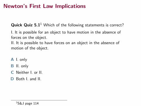
Newton’s First Law Implications
Quick Quiz 5.11 Which of the following statements is correct?
I. It is possible for an object to have motion in the absence offorces on the object.II. It is possible to have forces on an object in the absence ofmotion of the object.
A I. only
B II. only
C Neither I. or II.
D Both I. and II.
2S&J page 114
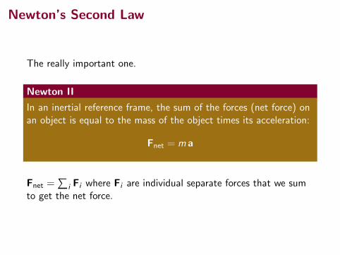
Newton’s Second Law
The really important one.
Newton II
In an inertial reference frame, the sum of the forces (net force) onan object is equal to the mass of the object times its acceleration:
Fnet = m a
Fnet =∑
i Fi where Fi are individual separate forces that we sumto get the net force.
Newton’s Second Law
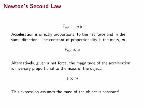
Fnet = m a
Acceleration is directly proportional to the net force and in thesame direction. The constant of proportionality is the mass, m.
Fnet ∝ a
Alternatively, given a net force, the magnitude of the accelerationis inversely proportional to the mass of the object.
a ∝ m
This expression assumes the mass of the object is constant!
Units of Force
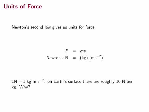
Newton’s second law gives us units for force.
F = ma
Newtons, N = (kg) (ms−2)
1N = 1 kg m s−2: on Earth’s surface there are roughly 10 N perkg. Why?
Newton’s Second Law Implications
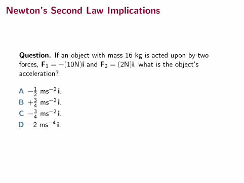
Question. If an object with mass 16 kg is acted upon by twoforces, F1 = −(10N)i and F2 = (2N)i, what is the object’sacceleration?
A −12 ms−2 i.
B +34 ms−2 i.
C −34 ms−2 i.
D −2 ms−4 i.
Newton’s Second Law Implications
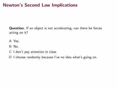
Question. If an object is not accelerating, can there be forcesacting on it?
A Yes.
B No.
C I don’t pay attention in class.
D I choose randomly because I’ve no idea what’s going on.
Newton’s Second Law Implications
Quick Quiz 5.3.2 You push an object, initially at rest, across africtionless floor with a constant force for a time interval ∆t,resulting in a final speed of v for the object. You then repeat theexperiment, but with a force that is twice as large. What timeinterval is now required to reach the same final speed v?
A 4∆t
B 2∆t
C ∆t2
D ∆t4
4S&J page 116.

Summary
• nonuniform circular motion
• Newton’s laws!
First Test Friday, Oct 13.
Quiz start of class, Monday. (Focus on Ch 4.)
(Uncollected) Homework Serway & Jewett,
• Ch 4, onward from page 104. Problems: 40, 43 (nonuniformcircular motion, set last time)
• Ch 5, onward from page 139. Problems: 3, 5, 9, 19