Stopper Cylinders - ASCO Asset Library/numatics-series-cst-stopper... · Table of Contents CST...
12
CST Series Stopper Cylinders www.numatics.com
-
Upload
duongquynh -
Category
Documents
-
view
226 -
download
0
Transcript of Stopper Cylinders - ASCO Asset Library/numatics-series-cst-stopper... · Table of Contents CST...

CST SeriesStopper Cylinders
w w w . n u m a t i c s . c o m
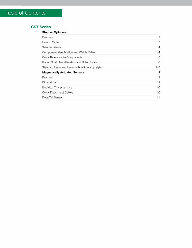
Table of Contents
CST Series Stopper Cylinders
Features 2
How to Order 3
Selection Guide 4
Component Identification and Weight Table 4
Quick Reference to Components 5
Round Shaft, Non-Rotating and Roller Styles 6
Standard Lever and Lever with lockout cup styles 7-8
Magnetically Actuated Sensors 9
Features 9
Dimensions 9
Electrical Characteristics 10
Quick Disconnect Cables 10
Dove Tail Sensor 11
Information subject to change without notice. For ordering information or regarding your local sales office visit www.numatics.com.3
CSTSERIES
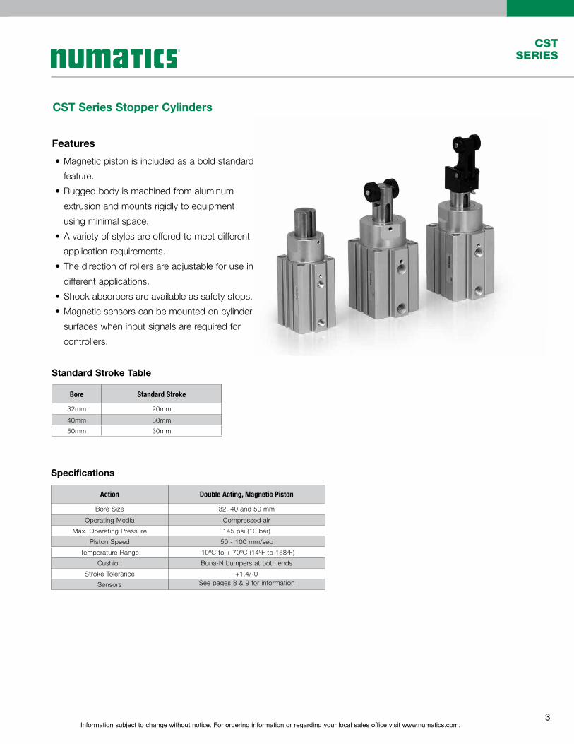
CST Series Stopper Cylinders
Features
•Magnetic piston is included as a bold standard
feature.
•Rugged body is machined from aluminum
extrusion and mounts rigidly to equipment
using minimal space.
•A variety of styles are offered to meet different
application requirements.
•The direction of rollers are adjustable for use in
different applications.
•Shock absorbers are available as safety stops.
•Magnetic sensors can be mounted on cylinder
surfaces when input signals are required for
controllers.
Action Double Acting, Magnetic Piston
Bore Size 32, 40 and 50 mm
Operating Media Compressed air
Max. Operating Pressure 145 psi (10 bar)
Piston Speed 50 - 100 mm/sec
Temperature Range -10ºC to + 70ºC (14ºF to 158ºF)
Cushion Buna-N bumpers at both ends
Stroke Tolerance +1.4/-0
Sensors
Bore Standard Stroke
32mm 20mm
40mm 30mm
50mm 30mm
Specifications
Standard Stroke Table
See pages 8 & 9 for information
Information subject to change without notice. For ordering information or regarding your local sales office visit www.numatics.com.4
CSTSERIES
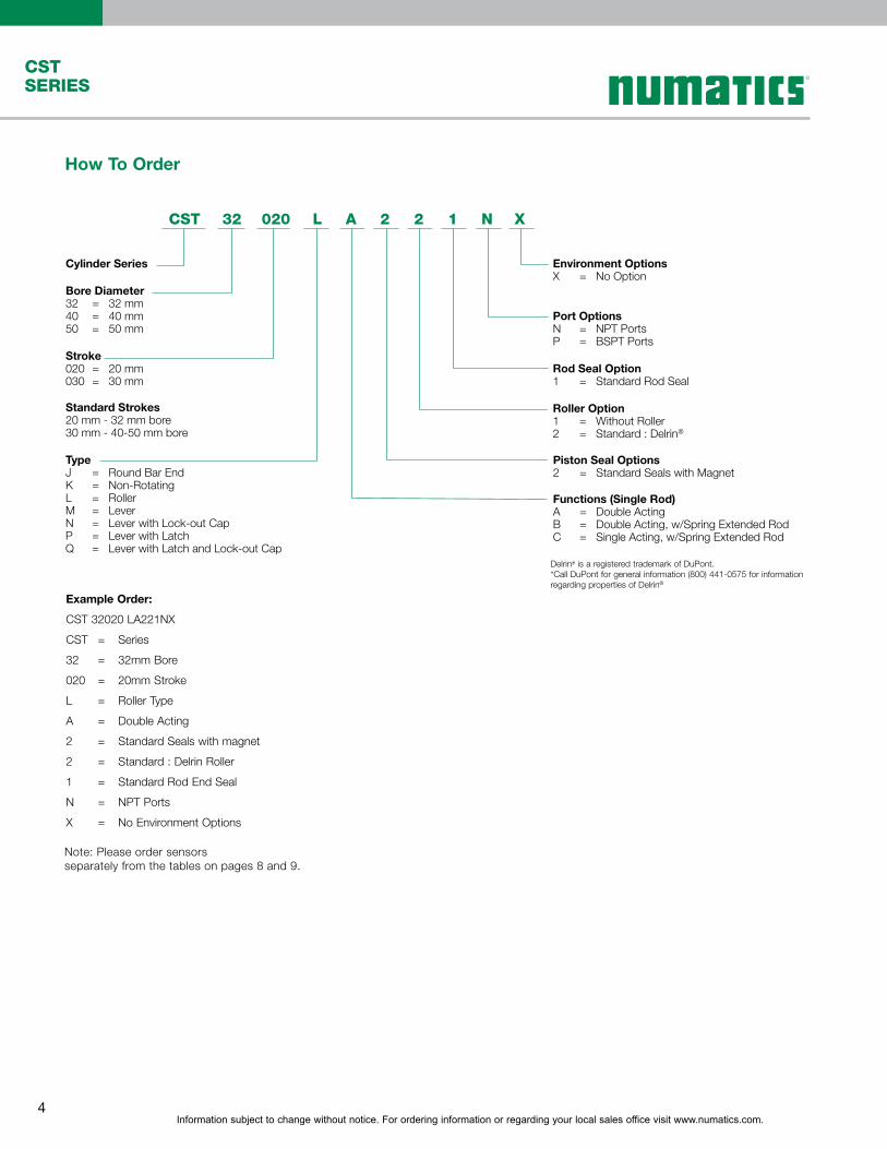
Example Order:
CST 32020 LA221NX
CST = Series
32 = 32mm Bore
020 = 20mm Stroke
L = Roller Type
A = Double Acting
2 = Standard Seals with magnet
2 = Standard : Delrin Roller
1 = Standard Rod End Seal
N = NPT Ports
X = No Environment Options
How To Order
Cylinder Series
Bore Diameter32 = 32 mm40 = 40 mm50 = 50 mm
Stroke020 = 20 mm030 = 30 mm
Standard Strokes20 mm - 32 mm bore30 mm - 40-50 mm bore
TypeJ = Round Bar EndK = Non-RotatingL = RollerM = LeverN = Lever with Lock-out CapP = Lever with LatchQ = Lever with Latch and Lock-out Cap
Environment OptionsX = No Option
Port OptionsN = NPT PortsP = BSPT Ports
Rod Seal Option1 = Standard Rod Seal
Roller Option1 = Without Roller2 = Standard : Delrin®
Piston Seal Options2 = Standard Seals with Magnet
Functions (Single Rod)A = Double ActingB = Double Acting, w/Spring Extended RodC = Single Acting, w/Spring Extended Rod
CST 32 020 L A 2 2 1 N X
Delrin® is a registered trademark of DuPont.*Call DuPont for general information (800) 441-0575 for information regarding properties of Delrin®
Note: Please order sensors separately from the tables on pages 8 and 9.
Information subject to change without notice. For ordering information or regarding your local sales office visit www.numatics.com.5
CSTSERIES
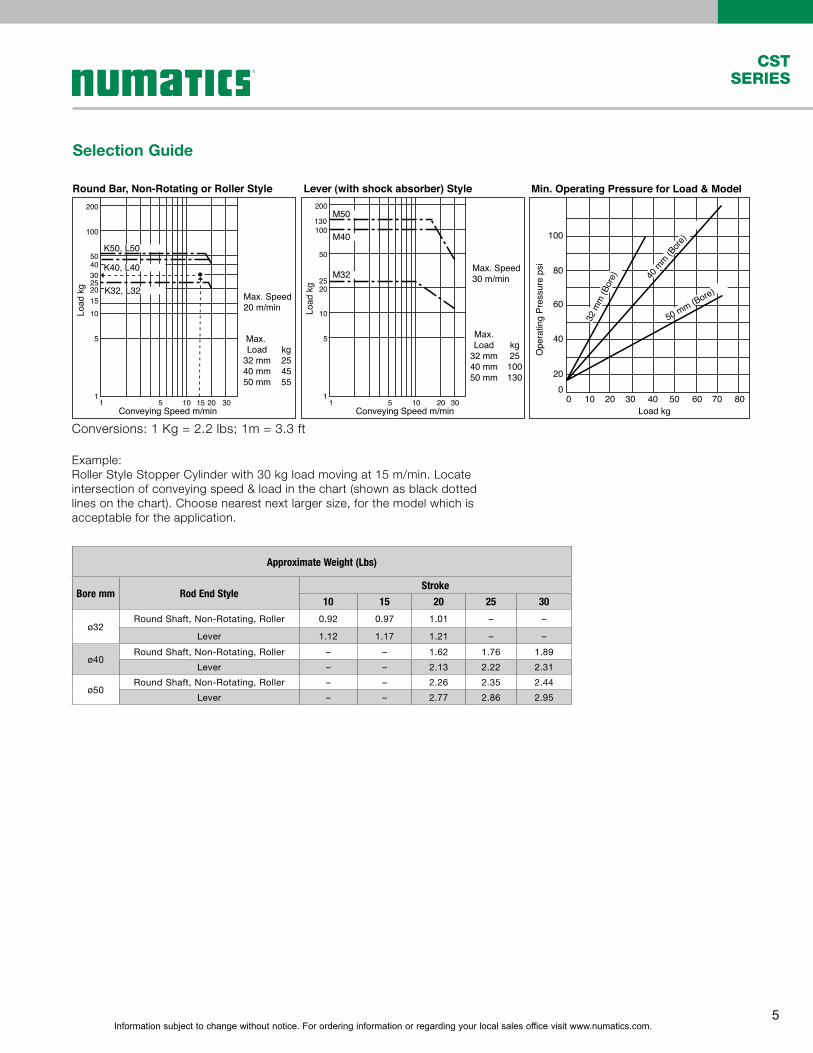
Approximate Weight (Lbs)
Bore mm Rod End StyleStroke
10 15 20 25 30
ø32Round Shaft, Non-Rotating, Roller 0.92 0.97 1.01 – –
Lever 1.12 1.17 1.21 – –
ø40Round Shaft, Non-Rotating, Roller – – 1.62 1.76 1.89
Lever – – 2.13 2.22 2.31
ø50Round Shaft, Non-Rotating, Roller – – 2.26 2.35 2.44
Lever – – 2.77 2.86 2.95
Selection Guide
Example:Roller Style Stopper Cylinder with 30 kg load moving at 15 m/min. Locate intersection of conveying speed & load in the chart (shown as black dotted lines on the chart). Choose nearest next larger size, for the model which is acceptable for the application.
Conversions: 1 Kg = 2.2 lbs; 1m = 3.3 ft
1
201510
5
25304050
100
200
1
20
40
60
80
100
20
10
5
25
50
100
200
130
Load
kg
Ope
ratin
g Pr
essu
re p
si
Load
kg
K50, L50
K40, L40
K32, L32
1 5 1510 20 30 1 5 10 20 30Conveying Speed m/min Conveying Speed m/min
M50
M40
M32
Round Bar, Non-Rotating or Roller Style Lever (with shock absorber) Style
00 10 20 30 40 50 60 70 80
Load kg
32 m
m (B
ore) 40
mm (B
ore)
50 mm (Bore)
Max. Speed30 m/min
Max.Load
32 mm40 mm50 mm
kg25100130
Max. Speed20 m/min
Max. Load
32 mm40 mm50 mm
kg254555
Min. Operating Pressure for Load & Model
Information subject to change without notice. For ordering information or regarding your local sales office visit www.numatics.com.6
CSTSERIES
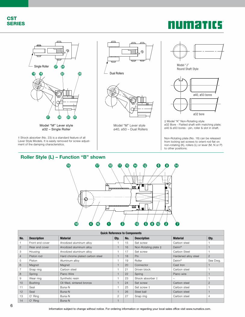
Dual Rollers
Model “M” Lever styleø32 – Single Roller
Model “M” Lever styleø40, ø50 – Dual Rollers
† Shock absorber (No. 23) is a standard feature of all Lever Style Models. It is easily removed for screw adjust-ment of the damping characteristics.
Quick Reference to Components
No. Description Material Qty. No. Description Material Qty.1 Front end cover Anodized aluminum alloy 1 15 Set screw Carbon steel 1
2 Rear end cover Anodized aluminum alloy 1 16 Non-Rotating plate ‡ Delrin® 1
3 Housing Anodized aluminum alloy 1 17 Set screw Carbon Steel 1
4 Piston rod Hard chrome plated carbon steel 1 18 Pin Hardened alloy steel 2
5 Piston Aluminum alloy 1 19 Roller Delrin® See Dwg.
6 Magnet Magnet 1 20 Connector Cast Iron 1
7 Snap ring Carbon steel 1 21 Driven block Carbon steel 1
8 Spring Piano Wire 1 22 Spring Piano wire 1
9 Wear ring Synthetic resin 1 23 Shock absorber † – 1
10 Bushing Oil filled, sintered bronze 1 24 Set screw Carbon steel 2
11 Seal Buna-N 1 25 Set screw † Carbon steel 1
12 Seal Buna-N 1 26 Steel ball Carbon steel 1
13 O’ Ring Buna-N 2 27 Snap ring Carbon steel 4
14 O’ Ring Buna-N 1
‡ Model “K” Non-Rotating style:ø32 Bore - Flatted shaft with matching plate; ø40 & ø50 bores - pin, roller & slot in shaft.
Non-Rotating plate (No. 16) can be released from locking set screws to orient rod flat on non-rotating (K), rollers (L) or lever (M, N or P) to other positions.
Model “J”Round Shaft Style
ø40, ø50 bores
ø32 bore
1719
18 4
9 14614 121110 15
1316 1 3 135 8 2 7
19 17 10 11 15 14 12 6 9 14
18 4 6 1 3 13 5 8 13 2 7
Roller Style (L) – Function “B” shown
2427
22
21 26 20 23
2519 18
Single Roller
19 18 22 25
21 26 26 23
2427
Information subject to change without notice. For ordering information or regarding your local sales office visit www.numatics.com.7
CSTSERIES
DA
A + (2 x Stroke)B + StrokeH + StrokeØD
X
AC + (2 x Stroke)
B + StrokeHC + Stroke
ØD
ØR
4
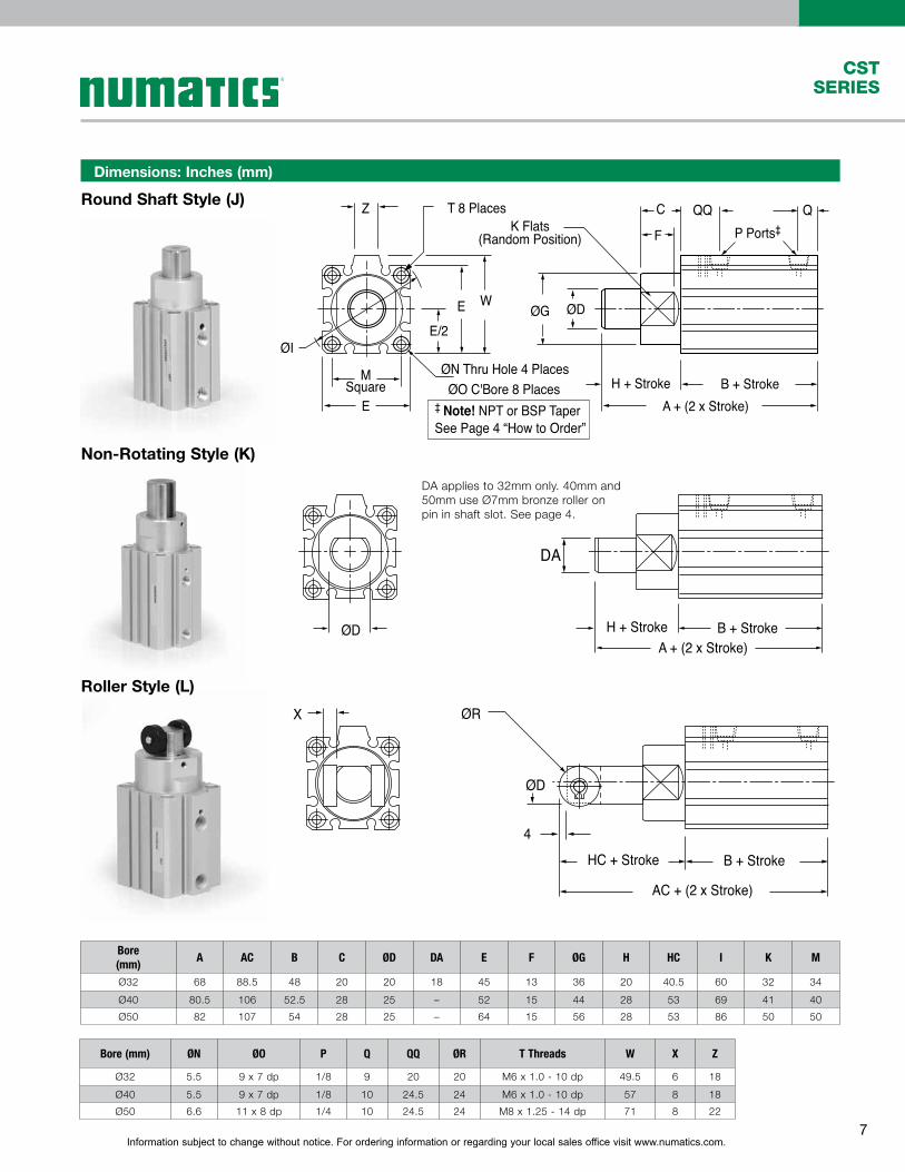
Round Shaft Style (J)
Non-Rotating Style (K)
Roller Style (L)
Bore(mm)
A AC B C ØD DA E F ØG H HC I K M
Ø32 68 88.5 48 20 20 18 45 13 36 20 40.5 60 32 34
Ø40 80.5 106 52.5 28 25 – 52 15 44 28 53 69 41 40
Ø50 82 107 54 28 25 – 64 15 56 28 53 86 50 50
Dimensions: Inches (mm)
Bore (mm) ØN ØO P Q QQ ØR T Threads W X Z
Ø32 5.5 9 x 7 dp 1/8 9 20 20 M6 x 1.0 - 10 dp 49.5 6 18
Ø40 5.5 9 x 7 dp 1/8 10 24.5 24 M6 x 1.0 - 10 dp 57 8 18
Ø50 6.6 11 x 8 dp 1/4 10 24.5 24 M8 x 1.25 - 14 dp 71 8 22
DA applies to 32mm only. 40mm and 50mm use Ø7mm bronze roller on pin in shaft slot. See page 4.
MSquare
E
E W
T 8 Places
A + (2 x Stroke)B + StrokeH + Stroke
ØI
QQC
F
QP Ports‡
ØG ØD
ØN Thru Hole 4 PlacesØO C'Bore 8 Places
K Flats(Random Position)
Z
E/2
‡ Note! NPT or BSP TaperSee Page 4 “How to Order”

Information subject to change without notice. For ordering information or regarding your local sales office visit www.numatics.com.8
CSTSERIES
Lever Style (M)
19
6
AD + (2 x Stroke)HD + Stroke
Ø32Single Roller
RX
RR
øRA Single Roller
RD
33
Ø40, Ø50Dual Rollers M
ovin
g Di
rect
ion
of
the
work
piec
e ca
rrier
Mov
ing
Dire
ctio
n of
th
e wo
rkpi
ece
carri
er
øRA Dual Rollers
QQC Q
B + StrokeMSquare
E
E W
T 8 Places
ØN Thru Hole 4 PlacesØO C'Bore 8 Places
6
AD + (2 x Stroke)HD + Stroke B + Stroke
ØG
Note! Cylinder housing dimensions not shown are the same as Round Shaft (J)
P Ports‡
‡ Note! NPT or BSP TaperSee Page 3 “How to Order”
Lever Style (N) – with lockout cap Lever Style (P) – with latch
Lever Style (Q) – with latch
and lockout cap.
Latch is the same as (Q); lockout cap is the same as (N).
A ball-chain retained lockout cap fits over the shock absorber stem to position the roller out of the conveyor stream.
When a work piece pushes the lever through the shock absorber stroke, the latch locks the lever in alignment to the rod. This reduces additional strokes to the shock absorber. The latching mechanism is released when the rod fully retracts.
Bore (mm) AD B C E ØG HD M ØN ØO
ø32 120.5 48 20 45 36 72.5 34 5.5 9x7 dp
ø40 152.5 52.5 28 52 44 100 40 5.5 9x7 dp
ø50 154 54 28 64 56 100 50 6.6 11x8 dp
Bore (mm) P Q QQ ØRA RD RR RX T Threads W
ø32 1/8 9 20 15 30° 28 10.5 M6 x 1.0 - 10 dp 49.5
ø40 1/8 10 24.5 20 24° 38 14 M6 x 1.0 - 10 dp 57
ø50 1/4 10 24.5 20 24° 38 14 M8 x 1.25 - 14 dp 71
Information subject to change without notice. For ordering information or regarding your local sales office visit www.numatics.com.9
CSTSERIES
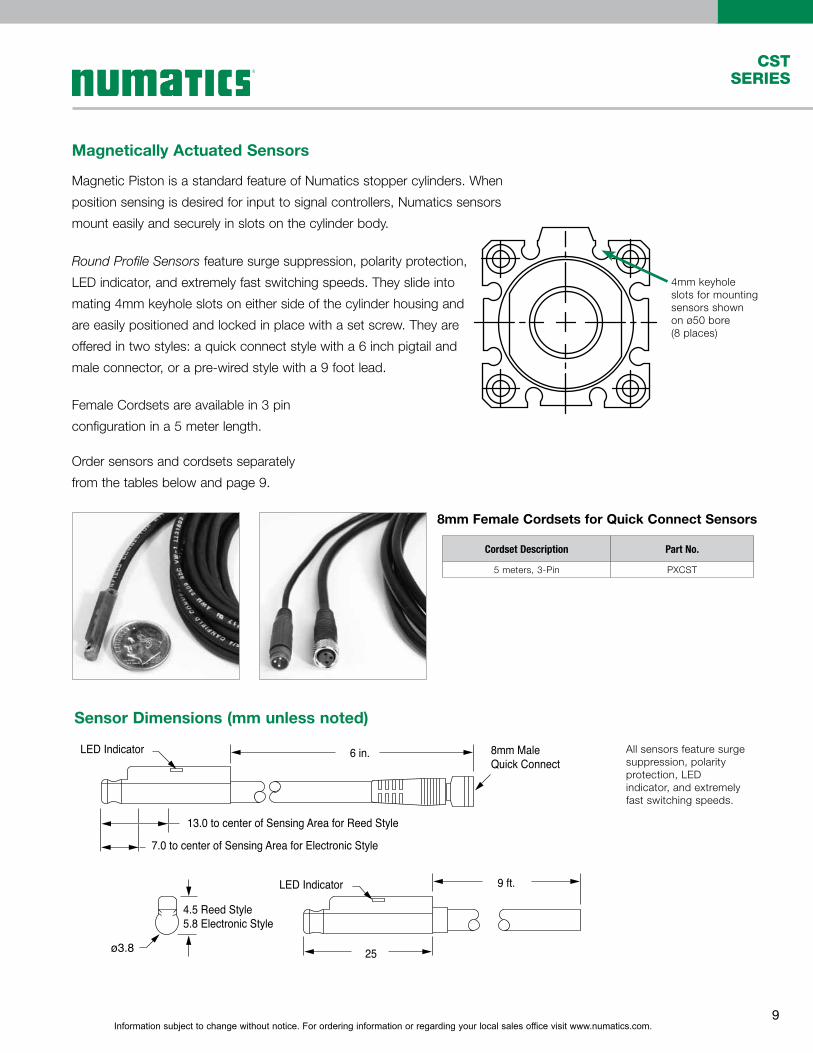
All sensors feature surge suppression, polarity protection, LED indicator, and extremely fast switching speeds.
Magnetically Actuated Sensors
Magnetic Piston is a standard feature of Numatics stopper cylinders. When
position sensing is desired for input to signal controllers, Numatics sensors
mount easily and securely in slots on the cylinder body.
4mm keyhole slots for mounting sensors shown on ø50 bore (8 places)
Female Cordsets are available in 3 pin
configuration in a 5 meter length.
Round Profile Sensors feature surge suppression, polarity protection,
LED indicator, and extremely fast switching speeds. They slide into
mating 4mm keyhole slots on either side of the cylinder housing and
are easily positioned and locked in place with a set screw. They are
offered in two styles: a quick connect style with a 6 inch pigtail and
male connector, or a pre-wired style with a 9 foot lead.
4.5 Reed Style5.8 Electronic Style
LED Indicator
LED Indicator
13.0 to center of Sensing Area for Reed Style
7.0 to center of Sensing Area for Electronic Style
9 ft.
25
6 in. 8mm Male Quick Connect
ø3.8
8mm Female Cordsets for Quick Connect Sensors
Sensor Dimensions (mm unless noted)
Cordset Description Part No.
5 meters, 3-Pin PXCST
Order sensors and cordsets separately
from the tables below and page 9.
Information subject to change without notice. For ordering information or regarding your local sales office visit www.numatics.com.10
CSTSERIES
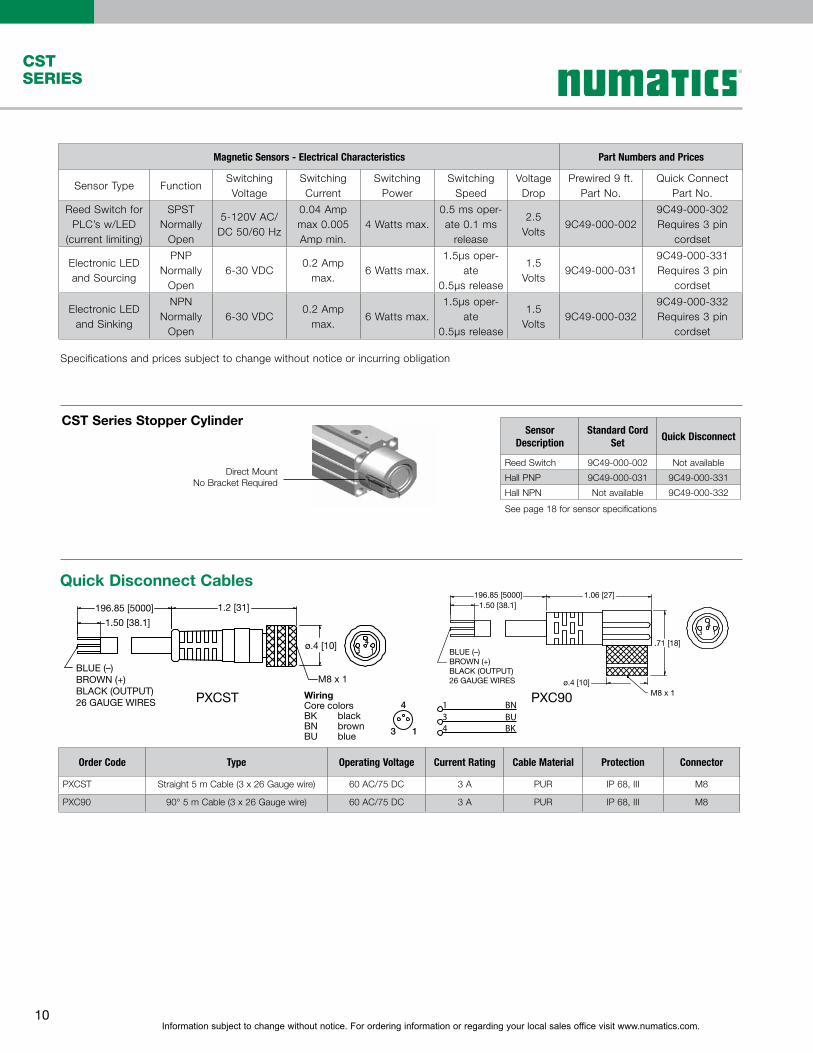
Specifications and prices subject to change without notice or incurring obligation
Magnetic Sensors - Electrical Characteristics Part Numbers and Prices
Sensor Type FunctionSwitching Voltage
SwitchingCurrent
Switching Power
Switching Speed
Voltage Drop
Prewired 9 ft. Part No.
Quick Connect Part No.
Reed Switch for PLC’s w/LED
(current limiting)
SPST Normally
Open
5-120V AC/DC 50/60 Hz
0.04 Amp max 0.005 Amp min.
4 Watts max.0.5 ms oper-ate 0.1 ms
release
2.5 Volts
9C49-000-0029C49-000-302Requires 3 pin
cordset
Electronic LED and Sourcing
PNP Normally
Open6-30 VDC
0.2 Amp max.
6 Watts max.1.5μs oper-
ate0.5μs release
1.5 Volts
9C49-000-0319C49-000-331Requires 3 pin
cordset
Electronic LED and Sinking
NPNNormally
Open6-30 VDC
0.2 Amp max.
6 Watts max.1.5μs oper-
ate0.5μs release
1.5 Volts
9C49-000-0329C49-000-332Requires 3 pin
cordset
CST Series Stopper CylinderSensor
DescriptionStandard Cord
SetQuick Disconnect
Reed Switch 9C49-000-002 Not available
Hall PNP 9C49-000-031 9C49-000-331
Hall NPN Not available 9C49-000-332
See page 18 for sensor specifications
Direct MountNo Bracket Required
196.85 [5000]
BLUE (–)BROWN (+)BLACK (OUTPUT)26 GAUGE WIRES
1.50 [38.1]
1.2 [31]
ø.4 [10]
M8 x 1
PXCST
Quick Disconnect Cables
Order Code Type Operating Voltage Current Rating Cable Material Protection Connector
PXCST Straight 5 m Cable (3 x 26 Gauge wire) 60 AC/75 DC 3 A PUR IP 68, III M8
PXC90 90° 5 m Cable (3 x 26 Gauge wire) 60 AC/75 DC 3 A PUR IP 68, III M8
BLUE (–)BROWN (+)BLACK (OUTPUT)26 GAUGE WIRES
196.85 [5000] 1.06 [27]
.71 [18]
M8 x 1ø.4 [10]
1.50 [38.1]
PXC90WiringCore colorsBK blackBN brownBU blue 13
4 1 BNBUBK
34

Information subject to change without notice. For ordering information or regarding your local sales office visit www.numatics.com.11
CSTSERIES
Dove tail Sensor with 45 Degree Wire
Dovetail Style Magnetic Sensor with LED
Sensor TypeStandard Cord
SetQuick Disconnect Electrical Characteristics
ElectronicElectronic
949-200-031949-200-032
949-200-331949-200-332
Sourcing PNP 6-24 VDC, 0.20 Amp Max current, 0.5 Voltage DropSinking NPN 6-24 VDC, 0.20 Amp Max current, 0.5 Voltage Drop
32(1.26)
34(1.34)
8.5(.33)
9.8(.39)
Sensor
Pigtail
1, 2 or 5
Meter Cable• Encased in a plastic housing, dovetail style
electronic sensors are corrosion resistant. 45° wire outlet allows close mounting.
Set Screw
60° Wire Outlet.14"
.24"
.75"
Note*: Quick disconnect styles are supplied with 6 inch pigtail with male connector. Order female cordsets separately.
Sensor Temperature Range-20° to +80° C (-4° to +176° F)

World Class Supplier of Pneumatic Components
World Headquarters
Numatics, Inc. | Tel (248) 596-3200 | www.numatics.com | email: [email protected] Catalog Rev 3/13 5M-TGI-03/11© Numatics Inc. 2008 - 2013 Numatics® is registered in the United States and elsewhere
USA Numatics, Incorporated46280 Dylan DriveNovi, Michigan 48377
P: 248-596-3200 F: 248-596-3201
Canada Numatics, LtdP: 519-758-2700 F: 519-758-5540
Brazil Ascoval Ind.e Comercio LtdaP: (55) 11-4208-1700 F: (55) 11-4195-3970
México - Ascomatica SA de CVP: 52 55 58 09 56 40 (DF y Area metropolitana)P: 01 800 000 ASCO (2726) (Interior de la República) F: 52 55 58 09 56 60