EVS-Series · EVS Control is a mode that all EVS Devices need to be in to be able to change the...
74
Installation and Operations Manual EVS-Series Emergency Voice System Document LS10062-001SK-E 02/12/13 Rev: A P/N LS100062-001SK-E ECN: 13-0146
Transcript of EVS-Series · EVS Control is a mode that all EVS Devices need to be in to be able to change the...

Installation andOperations Manual
EVS-SeriesEmergency Voice System
Document LS10062-001SK-E
02/12/13 Rev: AP/N LS100062-001SK-E ECN: 13-0146

Installation Procedure
Installation Precautions - Adherence to the following will aid in problem-free installation with long-term reliability: WARNING - Several different sources of power can be connected to the fire alarm control panel. Disconnect all sources of power before servicing. Control unit and associated equipment may be damaged by removing and/or inserting cards, modules, or interconnecting cables while the unit is energized. Do not attempt to install, service, or operate this unit until manuals are read and understood. CAUTION - System Re-acceptance Test after Software Changes: To ensure proper system operation, this product must be tested in accordance with NFPA 72 after any programming operation or change in site-specific software. Re-acceptance testing is required after any change, addition or deletion of system components, or after any modification, repair or adjustment to system hardware or wiring. All components, circuits, system operations, or software functions known to be affected by a change must be 100% tested. In addition, to ensure that other operations are not inadvertently affected, at least 10% of initiating devices that are not directly affected by the change, up to a maximum of 50 devices, must also be tested and proper system operation verified. This system meets NFPA requirements for operation within the range of 0°C-49°C (32°F-120°F) or humidity within the range of 10%-93% at 30°C (86°F) noncondensing. However, the useful life of the system's standby batteries and the electronic components may be adversely affected by extreme temperature ranges and humidity. Therefore, it is recommended that this system and its peripherals be installed in an environment with a normal room temperature of 15-27º C/60-80º F. Verify that wire sizes are adequate for all initiating and indicating device loops. Most devices cannot tolerate more than a 10% I.R. drop from the specified device voltage. Like all solid state electronic devices, this system may operate erratically or can be damaged when subjected to lightning induced transients. Although no system is completely immune from lightning transients and interference, proper grounding will reduce susceptibility. Overhead or outside aerial wiring is not recommended, due to an increased susceptibility to nearby lightning strikes. Consult with the Technical Services Department if any problems are anticipated or encountered. Remove DC power prior to removing or inserting circuit boards. Failure to do so can damage circuits. Remove all electronic assemblies prior to any drilling, filing, reaming, or punching of the enclosure. When possible, make all cable entries from the sides or rear. Before making modifications, verify that they will not interfere with battery, transformer, or printed circuit board location. Do not tighten screw terminals more than 9 in-lbs. Over-tightening may damage threads, resulting in reduced terminal contact pressure and difficulty with screw terminal removal. Fire alarm control panels contain static-sensitive components. Always ground yourself with a proper wrist strap before handling any circuits so that static charges are removed from the body. Use static suppressive packaging to protect electronic assemblies removed from the unit.
Follow the instructions in the installation, operating, and programming manuals.

These instructions must be followed to avoid damage to the control panel and associated equipment. FACP (Fire Alarm Control Panel) operation and reliability depend upon proper installation.
Equipment used in the system may not be technically compatible with the control. It is essential to use only equipment listed for service with your control panel. Telephone lines needed to transmit alarm signals from a premise to a central monitoring station may be out of service or temporarily disabled. The most common cause of fire alarm malfunctions, however, is inadequate maintenance. All devices and system wiring should be tested and maintained by professional fire alarm installers following written procedures supplied with each device. System inspection and testing should be scheduled monthly or as required by national and/or local fire codes. Adequate written records of all inspections should be kept.
1
Contents
Section 1Overview ...................................................................................................................................................... 1-1
1.1 Optional Accessories ................................................................................................................1-11.2 Features ...................................................................................................................................1-21.3 About This Manual ...................................................................................................................1-2
1.3.1 Terms Used in this Manual ................................................................................................1-31.4 How to Contact Silent Knight ....................................................................................................1-4
Section 2Agency Listings, Approvals, and Requirements ................................... 2-1
2.1 Federal Communications Commission (FCC) ..........................................................................2-12.2 Underwriters Laboratories (UL) ................................................................................................2-2
2.2.1 Requirements for All Installations ......................................................................................2-22.2.2 Requirements for Central Station Fire Alarm Systems ......................................................2-22.2.3 Requirements for Local Protected Fire Alarm Systems .....................................................2-22.2.4 Requirements for Remote Station Protected Fire Alarm Systems .....................................2-3
Section 3Before you Begin Installation .......................................................................................... 3-1
3.1 Environmental Specifications ...................................................................................................3-13.2 Wiring Specifications ................................................................................................................3-13.3 SBUS Specifications ................................................................................................................3-33.4 Electrical Specifications ............................................................................................................3-3
Section 4EVS Device Installation ............................................................................................................ 4-1
4.1 Mounting the Cabinet ...............................................................................................................4-14.1.1 Preventing Water Damage .................................................................................................4-14.1.2 Surface Mounting ...............................................................................................................4-14.1.3 Recessed Mounting ...........................................................................................................4-3
4.1.3.1 Cabinet Door and Dead Front Removal ...................................................................4-44.2 Connecting AC Power and Batteries ........................................................................................4-54.3 The EVS-VCM ..........................................................................................................................4-6
4.3.1 EVS-VCM Board Layout ....................................................................................................4-64.3.2 Connecting the EVS-VCM to the SBUS .............................................................................4-84.3.3 Installing the Microphone ...................................................................................................4-84.3.4 To Remove the EVS-VCM ...............................................................................................4-10
4.4 Installing the EVS-SW24 Switch Expander ............................................................................4-114.5 Installing the EVS-50W ..........................................................................................................4-13
4.5.1 EVS-50W Board Layout ...................................................................................................4-13

2
4.5.2 Mounting the EVS-50W ...................................................................................................4-144.5.3 Wiring Specifications ........................................................................................................4-154.5.4 Speaker Wiring ................................................................................................................4-16
4.5.4.1 Wiring Lengths .......................................................................................................4-174.5.4.2 Class B (Style Y) ....................................................................................................4-184.5.4.3 Class A (Style Z) ....................................................................................................4-18
4.5.5 VBUS Wiring ....................................................................................................................4-194.5.6 SBUS Wiring ....................................................................................................................4-204.5.7 Connecting AC Power ......................................................................................................4-214.5.8 Backup Battery for EVS-50W ...........................................................................................4-234.5.9 Calculating Current Draw and Standby Battery ...............................................................4-24
4.6 Installing the EVS-125W ........................................................................................................4-254.6.1 EVS-125W Board Layout .................................................................................................4-254.6.2 Mounting the EVS-125W .................................................................................................4-264.6.3 Wiring Specifications ........................................................................................................4-274.6.4 Speaker Wiring ................................................................................................................4-28
4.6.4.1 Wiring Lengths .......................................................................................................4-294.6.4.2 Class B (Style Y) ....................................................................................................4-304.6.4.3 Class A (Style Z) ....................................................................................................4-30
4.6.5 VBUS Wiring ....................................................................................................................4-314.6.6 SBUS Wiring ....................................................................................................................4-324.6.7 Connecting AC Power ......................................................................................................4-334.6.8 Backup Battery for EVS-125W .........................................................................................4-344.6.9 Calculating Current Draw and Standby Battery ...............................................................4-35
4.7 Installing the EVS-CE4 ...........................................................................................................4-364.8 Installing the EVS-RVM ..........................................................................................................4-38
4.8.1 EVS-RVM Board Layout ..................................................................................................4-384.8.2 Wiring the EVS-RVM .......................................................................................................4-404.8.3 Installing the Microphone .................................................................................................4-424.8.4 To Remove the EVS-RVM ...............................................................................................4-43
4.9 Addressing SBUS Devices .....................................................................................................4-45
Silent Knight Fire Product Warranty and Return Policy
Manufacturer Warranties and Limitation of Liability
LS10062-001-SK-E 1-1
Section 1Overview
The Emergency Voice System Packages are a combination of the addressable fire alarm control panel and voice integration control all in one package. The general idea of the Emergency Voice System is to activate a message giving building occupants instructions about an emergency event. This manual contains information on how to install and operate the following Emergency Voice System Packages:
1.1 Optional Accessories
This manual also contains information on how to install the following compatible accessory with the EVS series equipment:
Model Number Consists of These Part Numbers
EVS-Series5820XL-EVS
5820XL FACP
EVS-VCM (Voice control Module)
EVS-RCUEVS-RVM (Remote Voice Module)
5860 (Remote Annunciator)
Model Number Description
EVS-SW24Adds 24 additional switches to the EVS-VCM or EVS-RVM to manually select various voice output groups for emergency announcements from the on-board microphone
EVS-50W 50 watt amplifier with 4 separate audio circuits
EVS-125W 125 watt amplifier with 4 separate audio circuits
EVS-CE4 Provides four additional audio circuits for each EVS-50W
EVS Series Emergency Voice System Installation Manual
1-2 LS10062-001-SK-E
1.2 Features
EVS-Series
• The EVS-VCM has a built-in Digital Message Repeater.
• 15 recordable one minute messages that can be mapped to eight EVS.
• Single enclosure for system control components.
• SBUS addressable amplifier. The system can support a combination of up to fourEVS-50W 50 watt amplifier or EVS-125W 125 watt amplifiers for a maximum of 500 watts per system.
• On-board supervised microphone.
• 5820XL-EVS can support up to four EVS-RCU’s (Remote Command Units).
• Up to 32 mappable speaker circuits using a combination of EVS-50W or EVS-125W’s and EVS-CE4’s.
• Supports 25 Vrms or 70.7 Vrms speaker circuits using EVS-50W.
1.3 About This Manual
This manual is intended to be a complete reference for all installation and operation tasks. Please let us know if the manual does not meet your needs in any way. We value your feedback!

Overview
LS10062-001-SK-E 1-3
1.3.1 Terms Used in this Manual
The following terminology is used with the this system:
Term Description
EVSEmergency Voice System.The features of the control panel and accessories that provide Mass Notification functionality as described in UL standard 2572.
FACP Fire Alarm Control Panel
LOCLocal Operator's Console. The user interface for a Mass Notification System. In the Silent Knight product line, this would be the interface provided by the 5820XL-EVS or the EVS-RCU.
Mass NotificationA way of protecting life by relaying specific event information to a building or site including voice and/or audible and visual signals.
EVS-SeriesWhen this is used in a statement, it would indicate the that statement applies to the 5820XL-EVS control panels.
EVS DeviceA LOC or a 5880 module that is programmed as an EVS device. These are used as inputs for triggering the EVS.
EVS Control
EVS Control is a mode that all EVS Devices need to be in to be able to change the current state of the EVS. EVS Control is requested by using the EVS Control Button on LOC stations and is automatically requested for EVS 5880 Device contact triggers along with the EVS Aux Input triggers of the VCM and RVM.
EVS Device PriorityThe priority level which is programmed for ever EVS Device. In order from lowest to highest; Normal, Medium, High.
EVS Super UserA user profile provided option that allows the user to override all EVS Control rules and gain EVS Control.
VBUSThe VBUS is an analog voice bus that carries the recorded voice messages from the EVS-VCM to the EVS-50W/125Ws, or the voice messages generated from a system microphone to the EVS-50W/125W’s.
ModuleThe term module is used for all hardware devices except for SLC addressable devices and notification appliances.
Main control panel Refers to 5820XL-EVS control panel in the EVS-Series cabinet.
Input PointAn addressable sensing device, such as a smoke or heat detector or a contact monitor device.
Input Zone A protected area made up of input points.
Output Point(or Output Circuit)
A notification point or circuit for notification appliances. Relay circuits and auxiliary power circuits are also considered output points. The output group can be specifically defined as an output group to be used for voice evacuation circuits.
Audio Circuits Are output groups that are defined as voice output groups.
Group (or “Output Group”)A group of output points. Operating characteristics are common to all output points in the group.
Output (or “Cadence”) Pattern
The pattern that the output will use, for example, Constant, March Code, ANSI 3.41. Applies to zones and special system events.
MappingMapping is the process of specifying which outputs are activated when certain events occur in the system.

EVS Series Emergency Voice System Installation Manual
1-4 LS10062-001-SK-E
1.4 How to Contact Silent Knight
If you have a question or encounter a problem not covered in this manual, contact Silent Knight Technical Support at 800-446-6444. www.silentknight.com
To order parts, contact Silent Knight Sales at 800-328-0103.
Overview
LS10062-001-SK-E 1-5
Limitations of Fire Alarm Systems
Manufacturer recommends that smoke and/or heat detectors be located throughout a protected premise following the recommendations of the current edition of the National Fire Protection Association Standard 72 (NFPA 72), manufacturer’s recommendations, State and local codes, and the recommendations contained in Guide for the Proper Use of System Smoke Detectors, which is made available at no charge to all installing dealers. A study by the Federal Emergency Management Agency (an agency of the United States government) indicated that smoke detectors may not go off or give early warning in as many as 35% of all fires. While fire alarm systems are designed to provide warning against fire, they do not guarantee warning or protection against fire. A fire alarm system may not provide timely or adequate warning, or simply may not function, for a variety of reasons. For example:
• Particles of combustion or smoke from a developing fire may not reach the sensing chambers of smoke detectors because:
Barriers such as closed or partially closed doors, walls, or chimneys may inhibit particle or smoke flow.
Smoke particles may become cold stratify, and not reach the ceiling or upper walls where detectors are located.
Smoke particles may be blown away from detectors by air outlets.
Smoke particles may be drawn into air returns before reaching the detector.
In general, smoke detectors on one level of a structure cannot be expected to sense fires developing on another level.
• The amount of smoke present may be insufficient to alarm smoke detectors. Smoke detectors are designed to alarm at various levels of smoke density. If such density levels are not created by a developing fire at the location of detectors, the detectors will not go into alarm.
• Smoke detectors, even when working properly, have sensing limitations. Detectors that have photoelectric sensing chambers tend to detect smoldering fires better than flaming fires, which have little visible smoke. Detectors that have ionizing-type sensing chambers tend to detect fast flaming fires better than smoldering fires. Because fires develop in different ways and are often unpredictable in their growth, neither type of detector is necessarily best and a given type of detector may not provide adequate warning of a fire.
• Smoke detectors are subject to false alarms and nuisance alarms and may have been disconnected by users. For example, a smoke detector located in or near a kitchen may go into nuisance alarm during normal operation of kitchen appliances. In addition, dusty or steamy environments may cause a smoke detector to falsely alarm. If the location of a smoke detector causes an abundance of false alarms or nuisance alarms, do not disconnect the smoke detector; call a professional to analyze the situation and recommend a solution.
• Smoke detectors cannot be expected to provide adequate warning of fires caused
EVS Series Emergency Voice System Installation Manual
1-6 LS10062-001-SK-E
by arson, children playing with matches (especially within bedrooms), smoking in bed, violent explosions (caused by escaping gas, improper storage of flammable materials, etc.).
• Heat detectors do not sense particles of combustion and are designed to alarm only when heat on their sensors increases at a predetermined rate or reaches a predetermined level. Heat detectors are designed to protect property, not life.
• Warning devices (including horns, sirens, and bells) may not alert people or wake up sleepers who are located on the other side of closed or partially open doors. A warning device that activates on a different floor or level of a dwelling or structure is less likely to awaken or alert people. Even persons who are awake may not notice the warning if the alarm is muffled by noise from a stereo, radio, air conditioner or other appliance, or by passing traffic. Audible warning devices may not alert the hearing-impaired (strobes or other devices should be provided to warn these people). Any warning device may fail to alert people with a disability, deep sleepers, people who have recently used alcohol or drugs, or people on medication or sleeping pills.
Please note that:
i) Strobes can, under certain circumstances, cause seizures in people with con-ditions such as epilepsy.
ii) Studies have shown that certain people, even when they hear a fire alarm sig-nal, do not respond or comprehend the meaning of the signal. It is the property owner’s responsibility to conduct fire drills and other training exercises to make people aware of fire alarm signals and instruct on the proper reaction to alarm signals.
iii) In rare instances, the sounding of a warning device can cause temporary or permanent hearing loss.
• Telephone lines needed to transmit alarm signals from a premises to a central station may be out of service or temporarily out of service. For added protection against telephone line failure, backup radio transmission systems are recommended.
• System components, though designed to last many years, can fail at any time. As a precautionary measure, it is recommended that smoke detectors be checked, maintained, and replaced per manufacturer’s recommendations.
• System components will not work without electrical power. If system batteries are not serviced or replaced regularly, they may not provide battery backup when AC power fails.
• Environments with high air velocity or that are dusty or dirty require more frequent maintenance.
In general, fire alarm systems and devices will not work without power and will not function properly unless they are maintained and tested regularly.
While installing a fire alarm system may make the owner eligible for a lower insurance rate, an alarm system is not a substitute for insurance. Property owners should
Overview
LS10062-001-SK-E 1-7
continue to act prudently in protecting the premises and the people in their premises and should properly insure life and property and buy sufficient amounts of liability insurance to meet their needs.
Requirements and recommendations for proper use of fire alarm systems in-cluding smoke detectors and other fire alarm devices:
Early fire detection is best achieved by the installation and maintenance of fire detection equipment in all rooms and areas of the house or building in accordance with the requirements and recommendations of the current edition of the National Fire Protection Association Standard 72, National Fire Alarm Code (NFPA 72), the manufacturer’s recommendations, State and local codes and the recommendations contained in Guide for the Proper Use of System Smoke Detectors, which is made available at no charge to all installing dealers. For specific requirements, check with the local Authority Having Jurisdiction (ex. Fire Chief) for fire protection systems.
Requirements and Recommendations include:
• Smoke Detectors shall be installed in sleeping rooms in new construction and it is recommended that they shall also be installed in sleeping rooms in existing construction.
• It is recommended that more than one smoke detector shall be installed in a hallway if it is more than 30 feet long.
• It is recommended that there shall never be less then two smoke detectors per apartment or residence.
• It is recommended that smoke detectors be located in any room where an alarm control is located, or in any room where alarm control connections to an AC source or phone lines are made. If detectors are not so located, a fire within the room could prevent the control from reporting a fire.
• All fire alarm systems require notification devices, including sirens, bells, horns, and/or strobes. In residential applications, each automatic alarm initiating device when activated shall cause the operation of an alarm notification device that shall be clearly audible in all bedrooms over ambient or background noise levels (at least 15dB above noise) with all intervening doors closed.
• It is recommended that a smoke detector with an integral sounder (smoke alarm) be located in every bedroom and an additional notification device be located on each level of a residence.
• To keep your fire alarm system in excellent working order, ongoing maintenance is required per the manufacturer’s recommendations and UL and NFPA standards. At a minimum the requirements of Chapter 7 of NFPA 72 shall be followed. A maintenance agreement should be arranged through the local manufacturer’s representative. Maintenance should be performed annually by authorized personnel only.
The most common cause of an alarm system not functioning when a fire occurs is inadequate maintenance. As such, the alarm system should be tested weekly to
EVS Series Emergency Voice System Installation Manual
1-8 LS10062-001-SK-E
make sure all sensors and transmitters are working properly.
SURVIVABILITY:
Per the National Fire Alarm Code, NFPA 72, all circuits necessary for the operation of the notification appliances shall be protected until they enter the evacuation signaling zone that they serve. Any of the following methods shall be considered acceptable as meeting these requirements:1) A 2-hour rated cable or cable system2) A 2-hour rated enclosure3) Performance alternatives approved by Authority Having Jurisdiction
LS10062-001-SK-E 2-1
Section 2Agency Listings, Approvals, and Requirements
2.1 Federal Communications Commission (FCC)
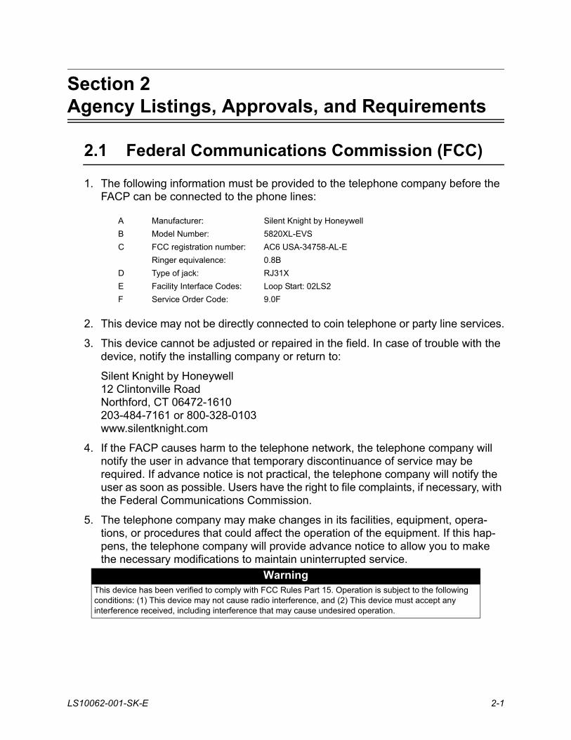
1. The following information must be provided to the telephone company before the FACP can be connected to the phone lines:
2. This device may not be directly connected to coin telephone or party line services.
3. This device cannot be adjusted or repaired in the field. In case of trouble with the device, notify the installing company or return to:
Silent Knight by Honeywell12 Clintonville RoadNorthford, CT 06472-1610203-484-7161 or 800-328-0103www.silentknight.com
4. If the FACP causes harm to the telephone network, the telephone company will notify the user in advance that temporary discontinuance of service may be required. If advance notice is not practical, the telephone company will notify the user as soon as possible. Users have the right to file complaints, if necessary, with the Federal Communications Commission.
5. The telephone company may make changes in its facilities, equipment, opera-tions, or procedures that could affect the operation of the equipment. If this hap-pens, the telephone company will provide advance notice to allow you to make the necessary modifications to maintain uninterrupted service.
A Manufacturer: Silent Knight by Honeywell
B Model Number: 5820XL-EVS
C FCC registration number: AC6 USA-34758-AL-E
Ringer equivalence: 0.8B
D Type of jack: RJ31X
E Facility Interface Codes: Loop Start: 02LS2
F Service Order Code: 9.0F
WarningThis device has been verified to comply with FCC Rules Part 15. Operation is subject to the following conditions: (1) This device may not cause radio interference, and (2) This device must accept any interference received, including interference that may cause undesired operation.
EVS Series Emergency Voice System Installation Manual
2-2 LS10062-001-SK-E
2.2 Underwriters Laboratories (UL)
2.2.1 Requirements for All Installations
General requirements are described in this section. When installing an individual device, refer to the specific section of the manual for additional requirements. The following subsections list specific requirements for each type of installation (for example, Central Station Fire Alarm systems, Local Protected Fire Alarm systems, and so on).
1. All field wiring must be installed in accordance with NFPA 70 National Electric Code.
2. Use the addressable smoke detectors specified in FACP installation manual.
3. Use UL listed notification appliances compatible with the FACP from those speci-fied in the Appendix at the back of this manual.
4. UL installations using Class B wiring for the speaker circuit require the use of an EOL resistor assembly.
5. A full system checkout must be performed any time the panel is programmed.
2.2.2 Requirements for Central Station Fire Alarm Systems
1. Use both phone lines. Enable phone line monitors for both lines.
2. You must program a phone number and a test time so that the FACP sends an automatic daily test to the central station.
3. Do not use the ground start option.
4. The AC Loss Hours option must be set from 1-3 hours.
5. The Attempts to Report option must be set for 5.
2.2.3 Requirements for Local Protected Fire Alarm Systems
At least one UL listed supervised notification appliance must be used.
Agency Listings, Approvals, and Requirements
LS10062-001-SK-E 2-3
2.2.4 Requirements for Remote Station Protected Fire Alarm Systems
1. Do not exceed the current load restrictions shown in FACP installation manual.
2. The AC Loss Hours option must be set from 1-3 hours.
The EVS-Series Control is UL listed as a voice evacuation unit for use in NFPA 72 systems. If the EVS-Series Control and its accessories are to be used as part of a UL installation, carefully read the UL requirements in this section. For more information on NFPA 72 standards, refer to the NFPA National Fire Alarm Code.

EVS Series Emergency Voice System Installation Manual
2-4 LS10062-001-SK-E

LS10062-001-SK-E 3-1
Section 3Before you Begin Installation
This section of the manual is intended to help you plan your tasks to complete the installation. Pleas read this section thoroughly, especially if you are installing a EVS-Series control for the first time.
3.1 Environmental Specifications
It is important to protect the control panel from water. To prevent water damage, the following precautions should be FOLLOWED when installing the units:
• Mount in indoor, dry environments only
• Do not mount directly on exterior walls, especially masonry walls (condensation)
• Do not mount directly on exterior walls below grade (condensation)
• Protect from plumbing leaks
• Protect from splash caused by sprinkler system inspection ports
• Do not mount in areas with humidity-generating equipment (such as dryers, production machinery)
When selecting a location to mount the control panel, the unit should be mounted where it will NOT be exposed to temperatures outside the range of 0°C-49°C (32°F-120°F) or humidity outside the range of 10%-93% at 30°C (86°F) noncondensing.
3.2 Wiring Specifications
Induced noise (transfer of electrical energy from one wire to another) can interfere with telephone communication or cause false alarms. To avoid induced noise, follow these guidelines:
• Isolate input wiring from high current output and power wiring. Do not pull one multi-conductor cable for the entire panel. Instead, separate the wiring as follows:
• Do not pull wires from different groups through the same conduit. If you must run them together, do so for as short a distance as possible or use shielded cable. Connect the shield to earth ground at the panel. You must route high and low voltages separately.
High voltage AC power Terminals
SLC loops Phone line circuits
Audio input/output NAC1 through NAC4
Notification circuits
SBUS
Relay circuits
EVS Series Emergency Voice System Installation Manual
3-2 LS10062-001-SK-E
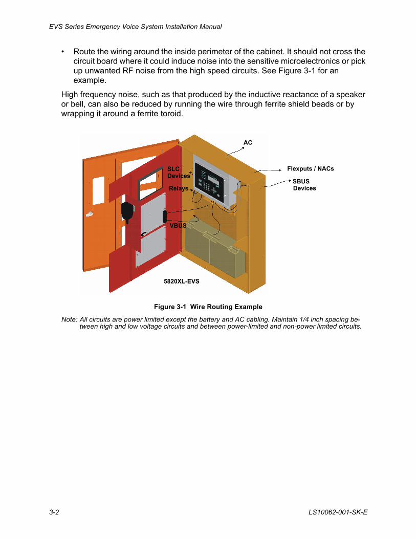
• Route the wiring around the inside perimeter of the cabinet. It should not cross the circuit board where it could induce noise into the sensitive microelectronics or pick up unwanted RF noise from the high speed circuits. See Figure 3-1 for an example.
High frequency noise, such as that produced by the inductive reactance of a speaker or bell, can also be reduced by running the wire through ferrite shield beads or by wrapping it around a ferrite toroid.
Figure 3-1 Wire Routing Example
Note: All circuits are power limited except the battery and AC cabling. Maintain 1/4 inch spacing be-tween high and low voltage circuits and between power-limited and non-power limited circuits.
SBUSDevices
Flexputs / NACs
VBUS
AC
Relays
SLCDevices
5820XL-EVS
Before you Begin Installation
LS10062-001-SK-E 3-3
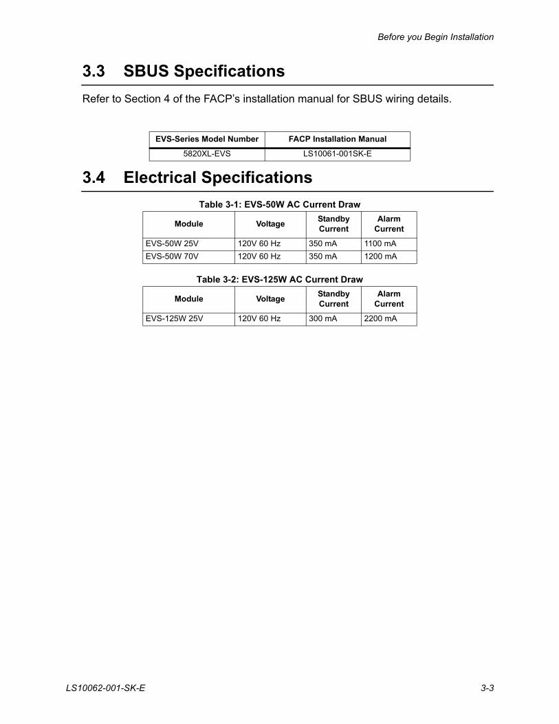
3.3 SBUS Specifications
Refer to Section 4 of the FACP’s installation manual for SBUS wiring details.
3.4 Electrical Specifications
Table 3-1: EVS-50W AC Current Draw
Table 3-2: EVS-125W AC Current Draw
EVS-Series Model Number FACP Installation Manual
5820XL-EVS LS10061-001SK-E
Module VoltageStandbyCurrent
AlarmCurrent
EVS-50W 25V 120V 60 Hz 350 mA 1100 mA
EVS-50W 70V 120V 60 Hz 350 mA 1200 mA
Module VoltageStandbyCurrent
AlarmCurrent
EVS-125W 25V 120V 60 Hz 300 mA 2200 mA

EVS Series Emergency Voice System Installation Manual
3-4 LS10062-001-SK-E
LS10062-001-SK-E 4-1
Section 4EVS Device Installation
4.1 Mounting the Cabinet
This section provides instructions on how to install the EVS series cabinet for surface or recessed mounting. Refer to Section 3.1 when choosing a mounting location.
4.1.1 Preventing Water Damage
Water damage to the fire system can be caused by moisture entering the cabinet through the conduit. Conduits that are installed to enter the top of the cabinet are most likely to cause water problems. Installers should take reasonable precautions to prevent water from entering the cabinet. Water damage is not covered under warranty.
4.1.2 Surface Mounting
The Cabinet can be mounted on the wall surface by using the mounting holes in the back of the cabinet (see 4.1).
The EVS-RCU Remote Command Unit is a combination EVS-RVM Remote Voice Module and its associated 5860 annunciator. The EVS-RCU is compatible with the Silent Knight 5820XL-EVS. For more information, refer to Installation manual for the 5820XL-EVS (PN LS10061-001SK-E).
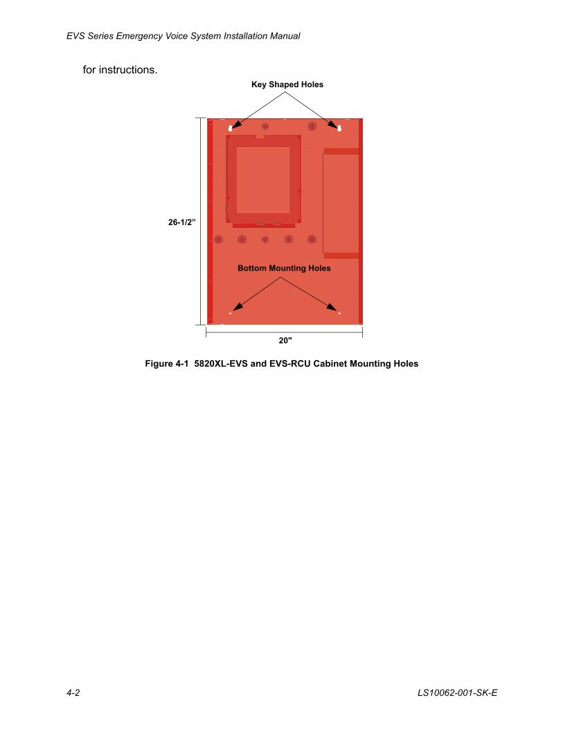
Cabinet dimensions are 20" W x 26½” H x 4.6" D.
1. Insert two screws level with each other, 14" apart for the top cabinet key shaped holes. See Figure 4-1.
2. Hang the cabinet onto the two screws. Tighten the screws down.
3. Insert two screws into the two bottom mounting holes and tighten them snug to the cabinet.
If you need to remove the cabinet door and the dead front panel, see Section 4.1.3.1
Caution!
To avoid the risk of electrical shock and damage to the unit, power should be OFF at the control panel while installing or servicing.
EVS Series Emergency Voice System Installation Manual
4-2 LS10062-001-SK-E
for instructions.
Figure 4-1 5820XL-EVS and EVS-RCU Cabinet Mounting Holes
Key Shaped Holes
Bottom Mounting Holes
20"
26-1/2”
EVS Device Installation
LS10062-001-SK-E 4-3
4.1.3 Recessed Mounting
This section describes how to recess mount the cabinet into a wall. To recess mount the cabinet you will need to have the optional trim ring P/N VIP-TR (ordered separately).
Follow these steps to recess mount the cabinet:
1. Remove the cabinet door and the dead front panel. See Section 4.1.3.1.
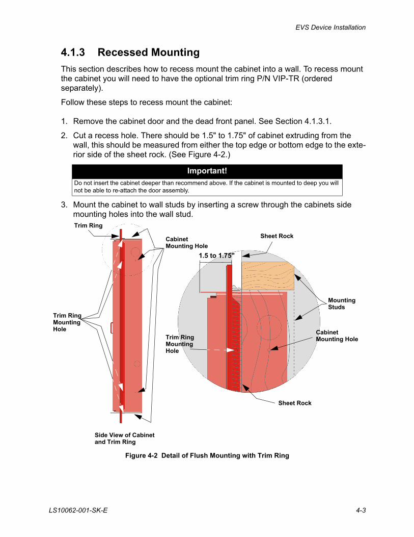
2. Cut a recess hole. There should be 1.5" to 1.75" of cabinet extruding from the wall, this should be measured from either the top edge or bottom edge to the exte-rior side of the sheet rock. (See Figure 4-2.)
3. Mount the cabinet to wall studs by inserting a screw through the cabinets side mounting holes into the wall stud.
Figure 4-2 Detail of Flush Mounting with Trim Ring
Important!
Do not insert the cabinet deeper than recommend above. If the cabinet is mounted to deep you will not be able to re-attach the door assembly.
Side View of Cabinet
Sheet Rock
Sheet Rock
MountingStuds
CabinetMounting Hole
Trim Ring MountingHole
CabinetMounting Hole
and Trim Ring
Trim Ring
1.5 to 1.75"
Trim Ring MountingHole
EVS Series Emergency Voice System Installation Manual
4-4 LS10062-001-SK-E
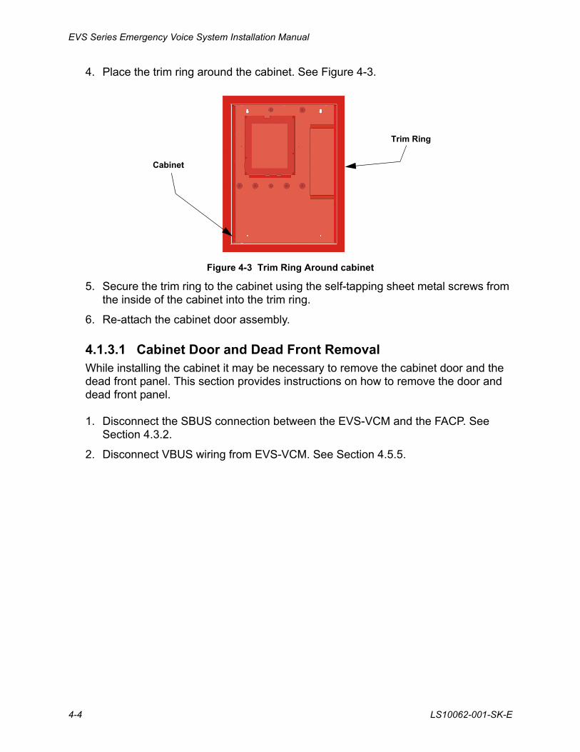
4. Place the trim ring around the cabinet. See Figure 4-3.
Figure 4-3 Trim Ring Around cabinet
5. Secure the trim ring to the cabinet using the self-tapping sheet metal screws from the inside of the cabinet into the trim ring.
6. Re-attach the cabinet door assembly.
4.1.3.1 Cabinet Door and Dead Front RemovalWhile installing the cabinet it may be necessary to remove the cabinet door and the dead front panel. This section provides instructions on how to remove the door and dead front panel.
1. Disconnect the SBUS connection between the EVS-VCM and the FACP. See Section 4.3.2.
2. Disconnect VBUS wiring from EVS-VCM. See Section 4.5.5.
Trim Ring
Cabinet
EVS Device Installation
LS10062-001-SK-E 4-5
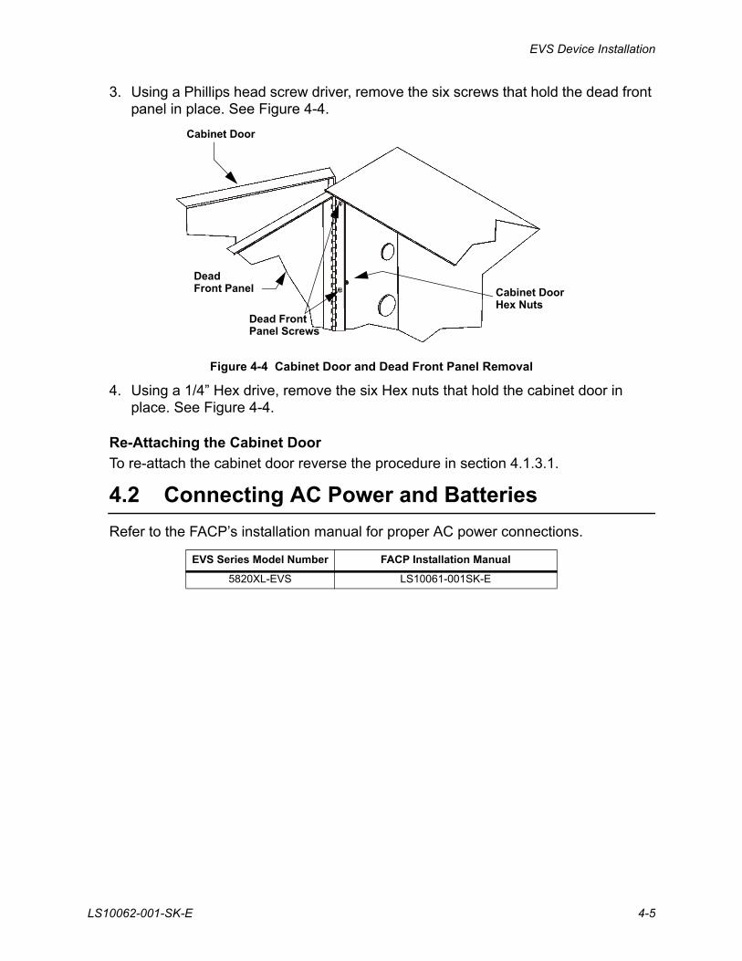
3. Using a Phillips head screw driver, remove the six screws that hold the dead front panel in place. See Figure 4-4.
Figure 4-4 Cabinet Door and Dead Front Panel Removal
4. Using a 1/4” Hex drive, remove the six Hex nuts that hold the cabinet door in place. See Figure 4-4.
Re-Attaching the Cabinet Door
To re-attach the cabinet door reverse the procedure in section 4.1.3.1.
4.2 Connecting AC Power and Batteries
Refer to the FACP’s installation manual for proper AC power connections.
EVS Series Model Number FACP Installation Manual
5820XL-EVS LS10061-001SK-E
Cabinet Door
Dead Front Panel
Dead FrontPanel Screws
Cabinet DoorHex Nuts
EVS Series Emergency Voice System Installation Manual
4-6 LS10062-001-SK-E
4.3 The EVS-VCM
The EVS-VCM Voice Control Module is contained within the Silent Knight EVS Series panel enclosure. It provides a supervised microphone for live communication and an interface for the Emergency Voice System. This section provides information on how to install or remove the EVS-VCM to the control cabinet and how to make the proper wiring connections.
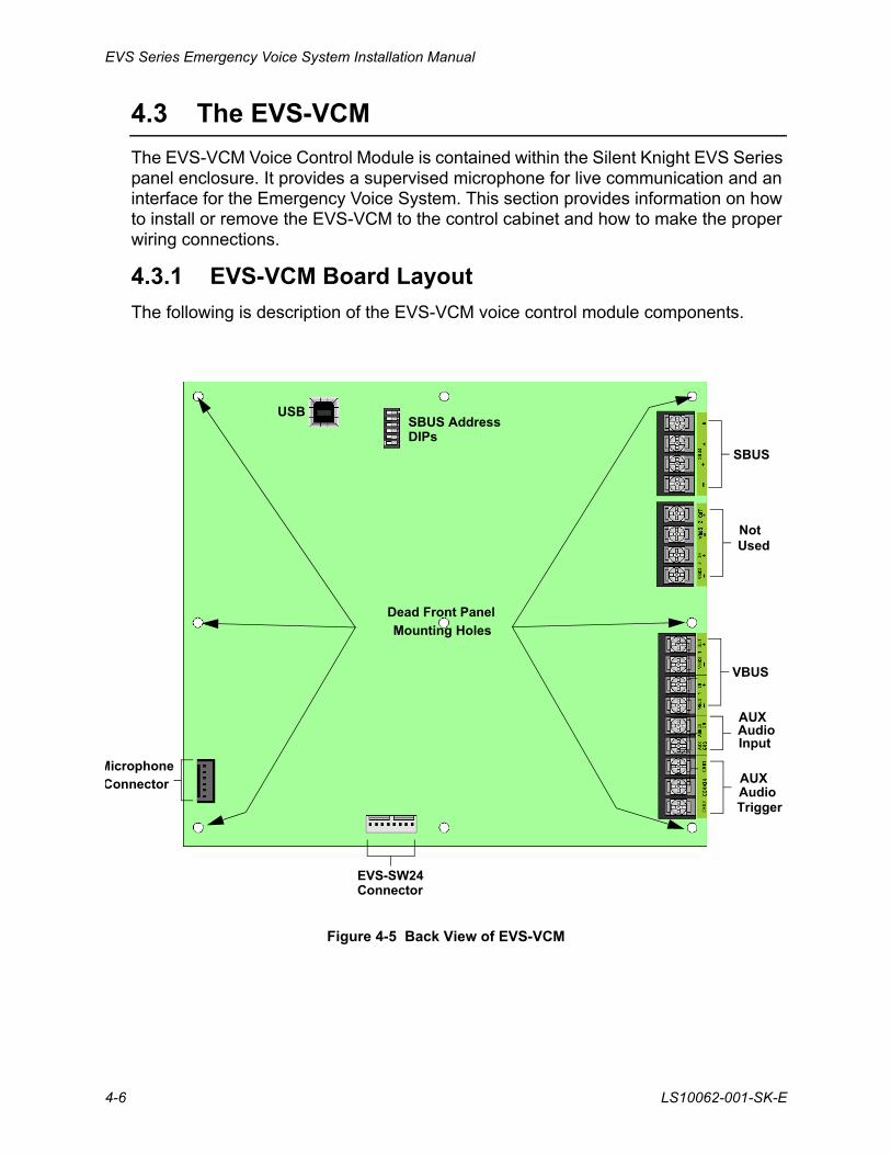
4.3.1 EVS-VCM Board Layout
The following is description of the EVS-VCM voice control module components.
Figure 4-5 Back View of EVS-VCM
AUX
SBUS AddressDIPs
Dead Front Panel
Mounting Holes
NotUsed
VBUS
USB
MicrophoneConnector
SBUS
Audio
Trigger
AUXAudio
Input
EVS-SW24Connector
EVS Device Installation
LS10062-001-SK-E 4-7
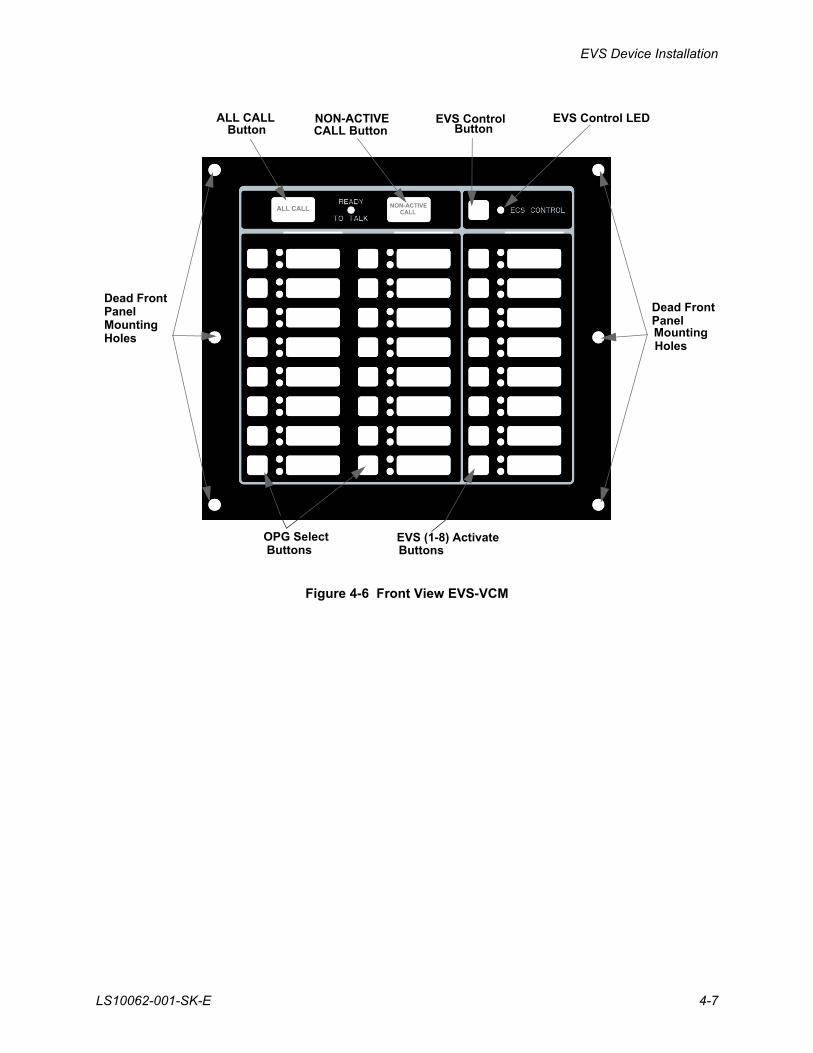
Figure 4-6 Front View EVS-VCM
Dead FrontPanel Dead Front
Panel
EVS (1-8) ActivateOPG Select
EVS Control LEDEVS ControlButton
ButtonsButtons
MountingHoles Mounting
Holes
ALL CALLButton
NON-ACTIVECALL Button
ALL CALL NON-ACTIVE CALL
EVS Series Emergency Voice System Installation Manual
4-8 LS10062-001-SK-E
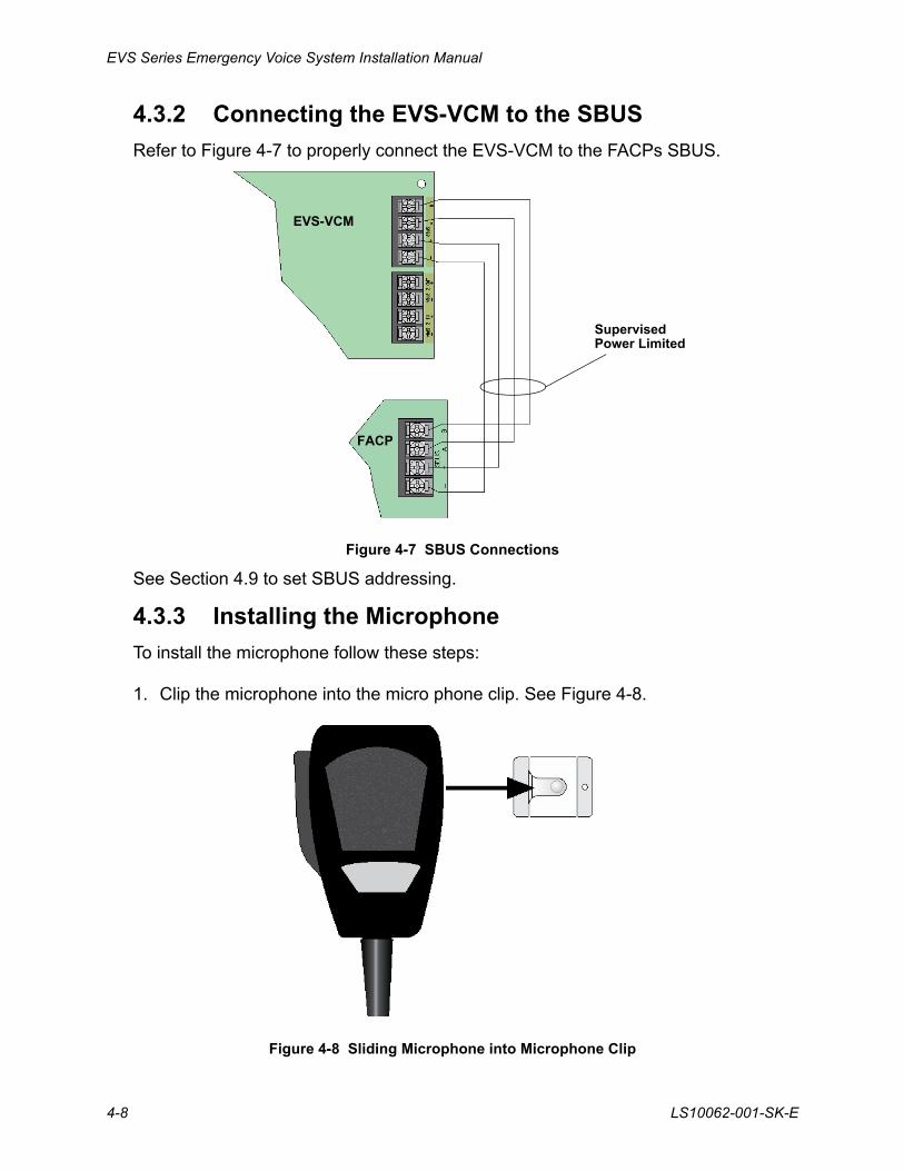
4.3.2 Connecting the EVS-VCM to the SBUS
Refer to Figure 4-7 to properly connect the EVS-VCM to the FACPs SBUS.
Figure 4-7 SBUS Connections
See Section 4.9 to set SBUS addressing.
4.3.3 Installing the Microphone
To install the microphone follow these steps:
1. Clip the microphone into the micro phone clip. See Figure 4-8.
Figure 4-8 Sliding Microphone into Microphone Clip
FACP
EVS-VCM
SupervisedPower Limited
EVS Device Installation
LS10062-001-SK-E 4-9
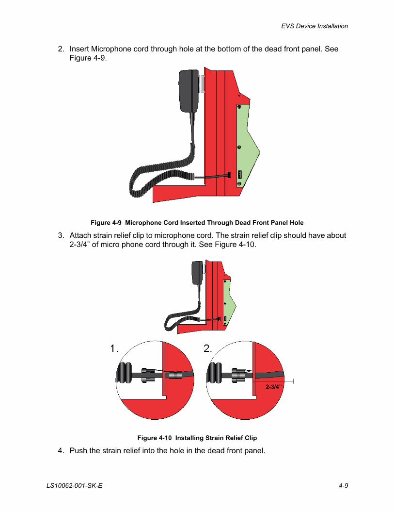
2. Insert Microphone cord through hole at the bottom of the dead front panel. See Figure 4-9.
Figure 4-9 Microphone Cord Inserted Through Dead Front Panel Hole
3. Attach strain relief clip to microphone cord. The strain relief clip should have about 2-3/4” of micro phone cord through it. See Figure 4-10.
Figure 4-10 Installing Strain Relief Clip
4. Push the strain relief into the hole in the dead front panel.
2-3/4”
EVS Series Emergency Voice System Installation Manual
4-10 LS10062-001-SK-E
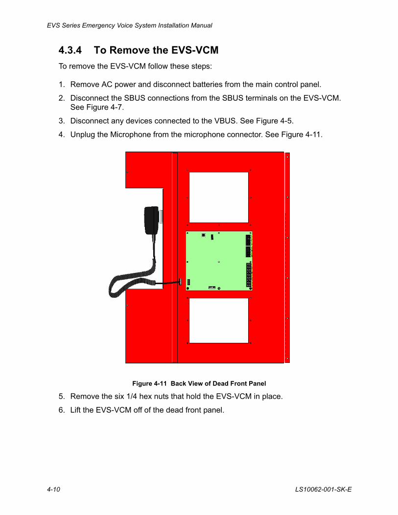
4.3.4 To Remove the EVS-VCM
To remove the EVS-VCM follow these steps:
1. Remove AC power and disconnect batteries from the main control panel.
2. Disconnect the SBUS connections from the SBUS terminals on the EVS-VCM. See Figure 4-7.
3. Disconnect any devices connected to the VBUS. See Figure 4-5.
4. Unplug the Microphone from the microphone connector. See Figure 4-11.
Figure 4-11 Back View of Dead Front Panel
5. Remove the six 1/4 hex nuts that hold the EVS-VCM in place.
6. Lift the EVS-VCM off of the dead front panel.
EVS Device Installation
LS10062-001-SK-E 4-11
4.4 Installing the EVS-SW24 Switch Expander
The EVS-SW24 adds 24 switches to the EVS-Series controls for a total of 40 (with the 16 Non-EVS switches on the EVS-VCM).
This section provides instruction on how to properly install the EVS-SW24.
Follow these steps to install the EVS-SW24:
1. Open Cabinet door and dead front panel.
2. Remove AC power from the main control panel.
3. Disconnect the backup batteries.
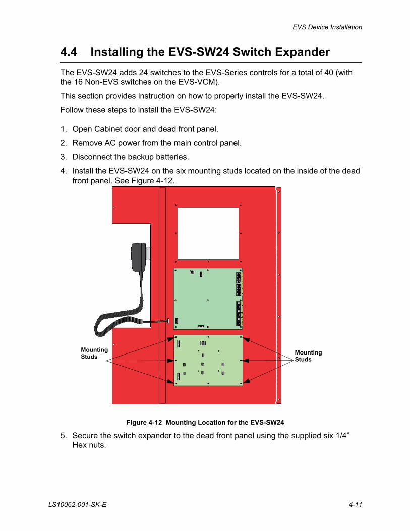
4. Install the EVS-SW24 on the six mounting studs located on the inside of the dead front panel. See Figure 4-12.
Figure 4-12 Mounting Location for the EVS-SW24
5. Secure the switch expander to the dead front panel using the supplied six 1/4” Hex nuts.
MountingStuds
MountingStuds
EVS Series Emergency Voice System Installation Manual
4-12 LS10062-001-SK-E
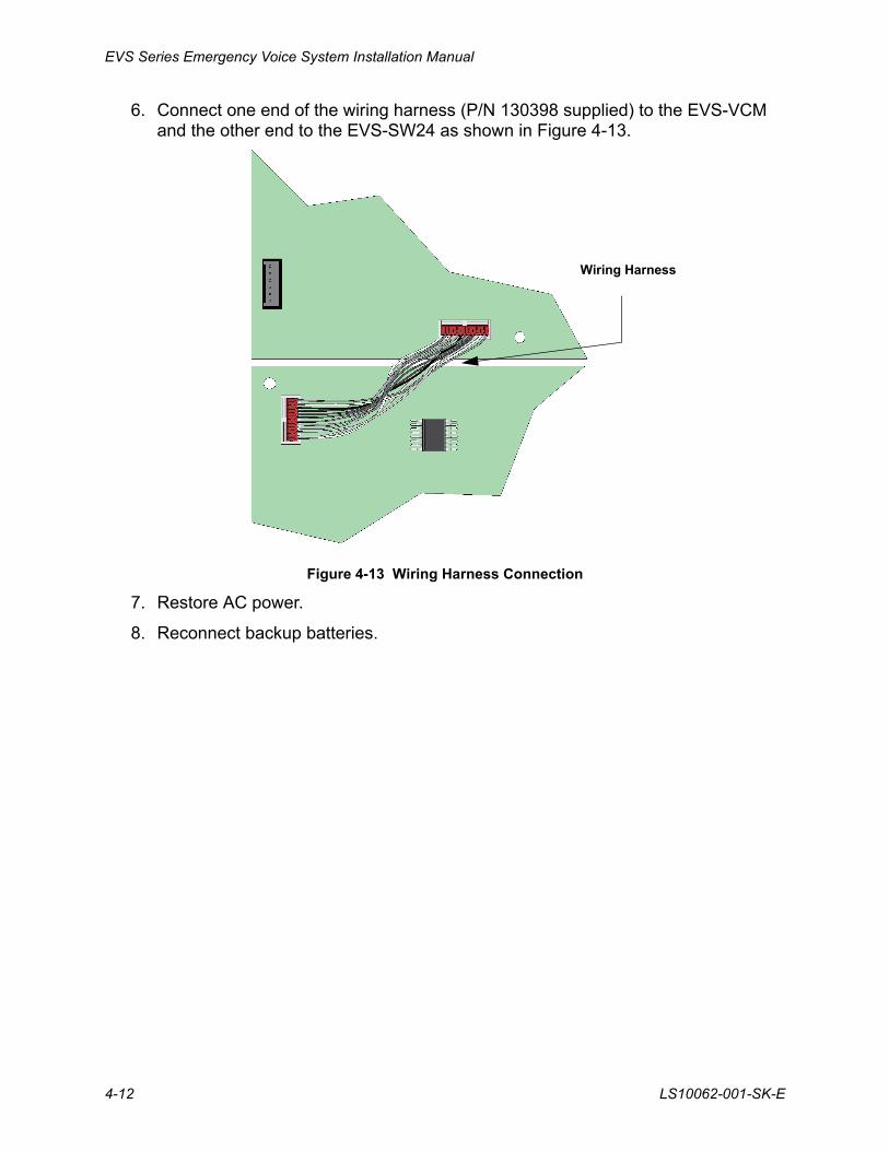
6. Connect one end of the wiring harness (P/N 130398 supplied) to the EVS-VCM and the other end to the EVS-SW24 as shown in Figure 4-13.
Figure 4-13 Wiring Harness Connection
7. Restore AC power.
8. Reconnect backup batteries.
Wiring Harness
EVS Device Installation
LS10062-001-SK-E 4-13
4.5 Installing the EVS-50W
This section provides information on how to install the EVS-50W for use with the EVS-Series products.
4.5.1 EVS-50W Board Layout
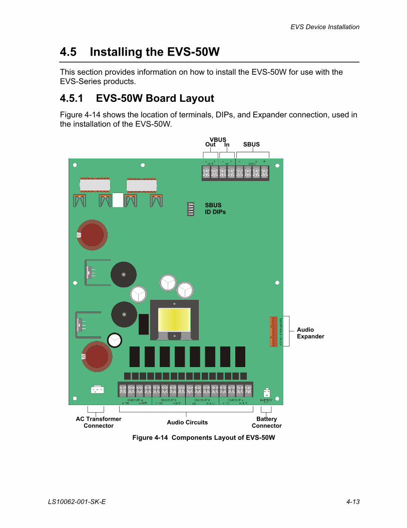
Figure 4-14 shows the location of terminals, DIPs, and Expander connection, used in the installation of the EVS-50W.
Figure 4-14 Components Layout of EVS-50W
VBUSInOut SBUS
SBUSID DIPs
Audio Circuits
AudioExpander
AC TransformerConnector
BatteryConnector
EVS Series Emergency Voice System Installation Manual
4-14 LS10062-001-SK-E
4.5.2 Mounting the EVS-50W
The EVS-50W is equipped with a separate enclosure. Refer to Section 4.1 when selecting a mounting location for the EVS-50W.
The panel should be accessible to main drop wiring runs. It should be mounted as close to the center of the building as possible and located within a secured area, but should be accessible for testing and service.
Mount the control panel cabinet so it is firmly secured to the wall surface. When mounting on concrete, especially when moisture is expected, attach a piece of 3/4-inch plywood to the concrete surface and then attach the cabinet to the plywood. Also mount any other modules to the plywood.
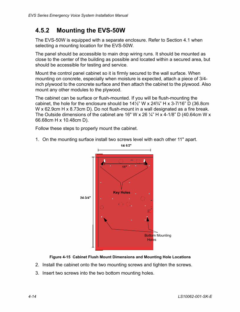
The cabinet can be surface or flush-mounted. If you will be flush-mounting the cabinet, the hole for the enclosure should be 14½” W x 24¾” H x 3-7/16” D (36.8cm W x 62.9cm H x 8.73cm D). Do not flush-mount in a wall designated as a fire break. The Outside dimensions of the cabinet are 16" W x 26 ¼” H x 4-1/8” D (40.64cm W x 66.68cm H x 10.48cm D).
Follow these steps to properly mount the cabinet.
1. On the mounting surface install two screws level with each other 11" apart.
Figure 4-15 Cabinet Flush Mount Dimensions and Mounting Hole Locations
2. Install the cabinet onto the two mounting screws and tighten the screws.
3. Insert two screws into the two bottom mounting holes.
Key Holes
Bottom Mounting Holes
EVS Device Installation
LS10062-001-SK-E 4-15
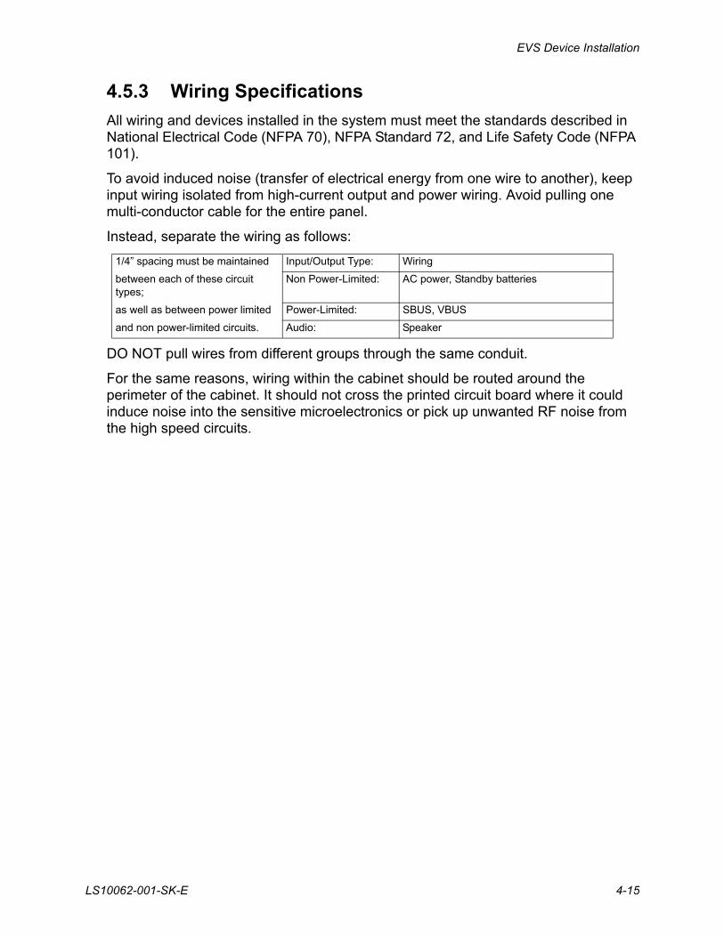
4.5.3 Wiring Specifications
All wiring and devices installed in the system must meet the standards described in National Electrical Code (NFPA 70), NFPA Standard 72, and Life Safety Code (NFPA 101).
To avoid induced noise (transfer of electrical energy from one wire to another), keep input wiring isolated from high-current output and power wiring. Avoid pulling one multi-conductor cable for the entire panel.
Instead, separate the wiring as follows:
DO NOT pull wires from different groups through the same conduit.
For the same reasons, wiring within the cabinet should be routed around the perimeter of the cabinet. It should not cross the printed circuit board where it could induce noise into the sensitive microelectronics or pick up unwanted RF noise from the high speed circuits.
1/4” spacing must be maintained Input/Output Type: Wiring
between each of these circuit types;
Non Power-Limited: AC power, Standby batteries
as well as between power limited Power-Limited: SBUS, VBUS
and non power-limited circuits. Audio: Speaker
EVS Series Emergency Voice System Installation Manual
4-16 LS10062-001-SK-E
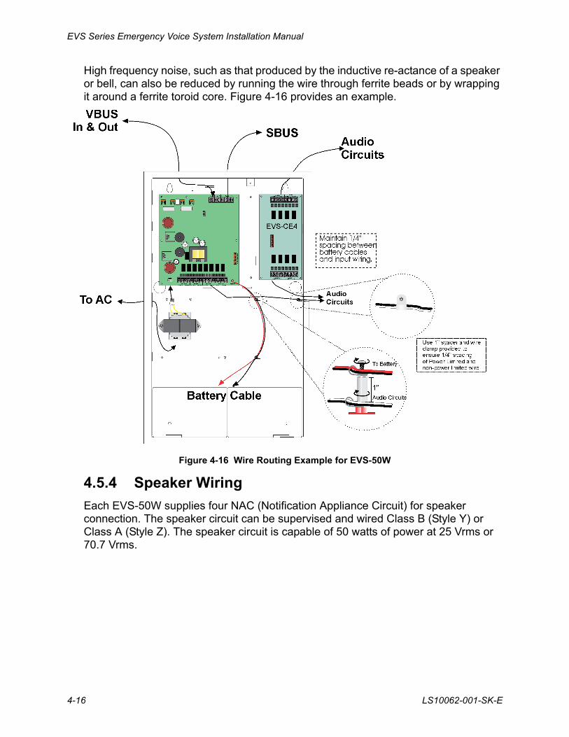
High frequency noise, such as that produced by the inductive re-actance of a speaker or bell, can also be reduced by running the wire through ferrite beads or by wrapping it around a ferrite toroid core. Figure 4-16 provides an example.
Figure 4-16 Wire Routing Example for EVS-50W
4.5.4 Speaker Wiring
Each EVS-50W supplies four NAC (Notification Appliance Circuit) for speaker connection. The speaker circuit can be supervised and wired Class B (Style Y) or Class A (Style Z). The speaker circuit is capable of 50 watts of power at 25 Vrms or 70.7 Vrms.

EVS Device Installation
LS10062-001-SK-E 4-17
4.5.4.1 Wiring Lengths
Note: The above table assumes a uniform distribution of the speakers, and that a max of 20% voltage drop on the last speaker is allowed.
Table 4-1 Wire Lengths
Number Of Speakers Total Load Wire Distance in Feet
@1/2 W @1 W Vrms Watts 18 AWG 16 AWG 14 AWG 12 AWG
10 5 25Vrms 5W 3900 6200 9860 15680
70Vrms 25000 39700 63200 100520
20 10 25Vrms 10W 2125 3380 5375 8540
70Vrms 15200 24150 38400 61100
30 15 25Vrms 15W 1460 2320 3690 5870
70Vrms 11000 17500 27800 44200
40 20 25Vrms 20W 1100 1750 2780 4420
70Vrms 8500 13510 21500 34175
52 26 25Vrms 26W 760 1200 1920 3050
70Vrms 6100 9700 15400 24520
80 40 25Vrms 40W 550 875 1390 2200
70Vrms 4100 6500 10360 16480
100 50 25Vrms 50W 450 715 1130 1800
70Vrms 3500 5560 8850 14070
EVS Series Emergency Voice System Installation Manual
4-18 LS10062-001-SK-E
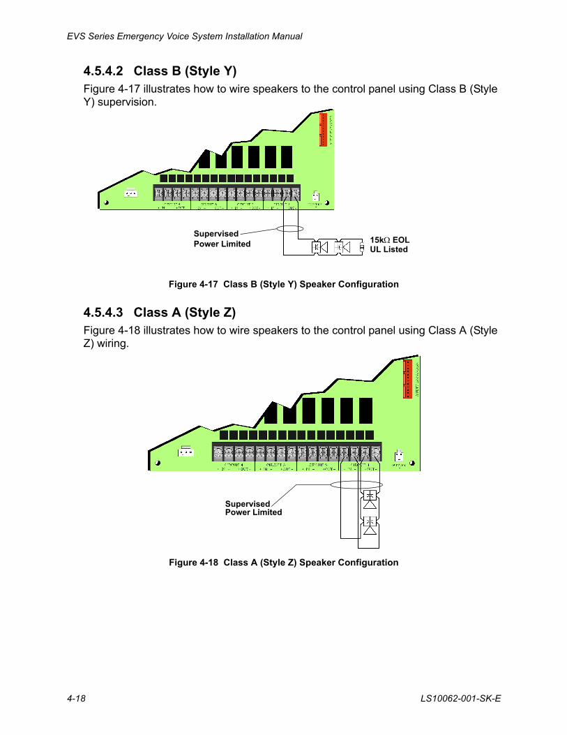
4.5.4.2 Class B (Style Y)Figure 4-17 illustrates how to wire speakers to the control panel using Class B (Style Y) supervision.
Figure 4-17 Class B (Style Y) Speaker Configuration
4.5.4.3 Class A (Style Z)Figure 4-18 illustrates how to wire speakers to the control panel using Class A (Style Z) wiring.
Figure 4-18 Class A (Style Z) Speaker Configuration
15k EOLUL Listed
SupervisedPower Limited
SupervisedPower Limited
EVS Device Installation
LS10062-001-SK-E 4-19
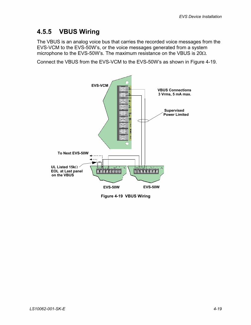
4.5.5 VBUS Wiring
The VBUS is an analog voice bus that carries the recorded voice messages from the EVS-VCM to the EVS-50W’s, or the voice messages generated from a system microphone to the EVS-50W’s. The maximum resistance on the VBUS is 20.
Connect the VBUS from the EVS-VCM to the EVS-50W’s as shown in Figure 4-19.
Figure 4-19 VBUS Wiring
To Next EVS-50W
UL Listed 15kEOL
EVS-VCM
EVS-50WEVS-50W
SupervisedPower Limited
at Last panelon the VBUS
VBUS Connections3 Vrms, 5 mA max.
EVS Series Emergency Voice System Installation Manual
4-20 LS10062-001-SK-E
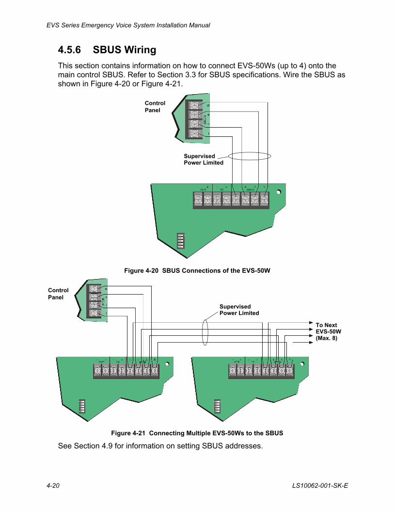
4.5.6 SBUS Wiring
This section contains information on how to connect EVS-50Ws (up to 4) onto the main control SBUS. Refer to Section 3.3 for SBUS specifications. Wire the SBUS as shown in Figure 4-20 or Figure 4-21.
Figure 4-20 SBUS Connections of the EVS-50W
Figure 4-21 Connecting Multiple EVS-50Ws to the SBUS
See Section 4.9 for information on setting SBUS addresses.
SupervisedPower Limited
Control Panel
SupervisedPower Limited
To NextEVS-50W(Max. 8)
ControlPanel
EVS Device Installation
LS10062-001-SK-E 4-21
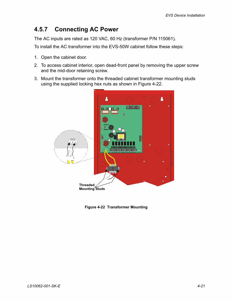
4.5.7 Connecting AC Power
The AC inputs are rated as 120 VAC, 60 Hz (transformer P/N 115061).
To install the AC transformer into the EVS-50W cabinet follow these steps:
1. Open the cabinet door.
2. To access cabinet interior, open dead-front panel by removing the upper screw and the mid-door retaining screw.
3. Mount the transformer onto the threaded cabinet transformer mounting studs using the supplied locking hex nuts as shown in Figure 4-22.
Figure 4-22 Transformer Mounting
ThreadedMounting Studs
EVS Series Emergency Voice System Installation Manual
4-22 LS10062-001-SK-E
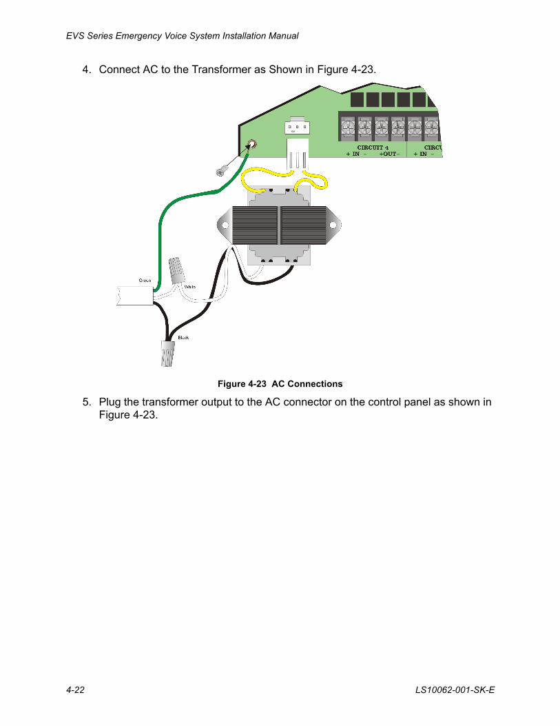
4. Connect AC to the Transformer as Shown in Figure 4-23.
Figure 4-23 AC Connections
5. Plug the transformer output to the AC connector on the control panel as shown in Figure 4-23.
EVS Device Installation
LS10062-001-SK-E 4-23
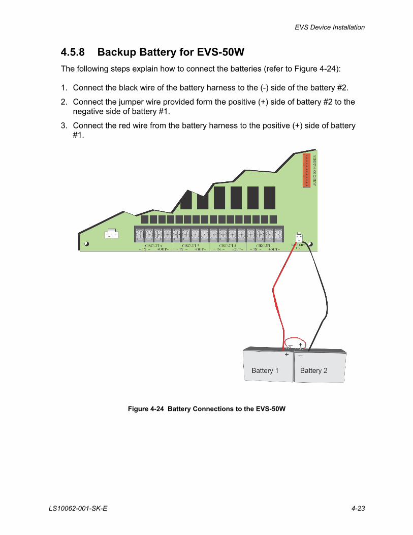
4.5.8 Backup Battery for EVS-50W
The following steps explain how to connect the batteries (refer to Figure 4-24):
1. Connect the black wire of the battery harness to the (-) side of the battery #2.
2. Connect the jumper wire provided form the positive (+) side of battery #2 to the negative side of battery #1.
3. Connect the red wire from the battery harness to the positive (+) side of battery #1.
Figure 4-24 Battery Connections to the EVS-50W
EVS Series Emergency Voice System Installation Manual
4-24 LS10062-001-SK-E
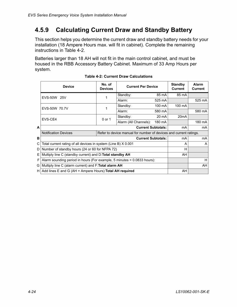
4.5.9 Calculating Current Draw and Standby Battery
This section helps you determine the current draw and standby battery needs for your installation (18 Ampere Hours max. will fit in cabinet). Complete the remaining instructions in Table 4-2.
Batteries larger than 18 AH will not fit in the main control cabinet, and must be housed in the RBB Accessory Battery Cabinet. Maximum of 33 Amp Hours per system.
Table 4-2: Current Draw Calculations
DeviceNo. of
DevicesCurrent Per Device
Standby Current
Alarm Current
EVS-50W 25V 1Standby: 85 mA 85 mA
Alarm: 525 mA 525 mA
EVS-50W 70.7V 1Standby: 100 mA 100 mA
Alarm: 580 mA 580 mA
EVS-CE4 0 or 1Standby: 20 mA 20mA
Alarm (All Channels): 180 mA 180 mA
A Current Subtotals: mA mA
Notification Devices Refer to device manual for number of devices and current ratings.
B Current Subtotals: mA mA
C Total current rating of all devices in system (Line B) X 0.001 A A
D Number of standby hours (24 or 60 for NFPA 72) H
E Multiply line C (standby current) and D:Total standby AH AH
F Alarm sounding period in hours (For example, 5 minutes = 0.0833 hours): H
G Multiply line C (alarm current) and F:Total alarm AH AH
H Add lines E and G (AH = Ampere Hours):Total AH required AH
EVS Device Installation
LS10062-001-SK-E 4-25
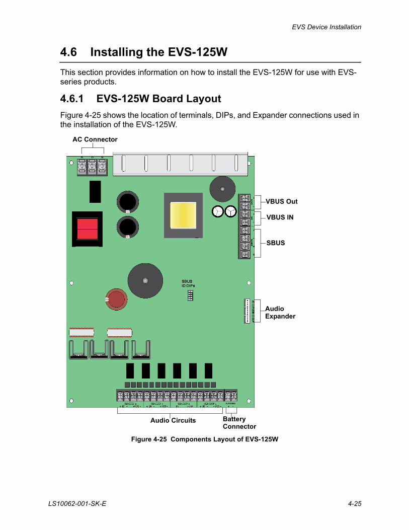
4.6 Installing the EVS-125W
This section provides information on how to install the EVS-125W for use with EVS-series products.
4.6.1 EVS-125W Board Layout
Figure 4-25 shows the location of terminals, DIPs, and Expander connections used in the installation of the EVS-125W.
Figure 4-25 Components Layout of EVS-125W
AC Connector
VBUS Out
VBUS IN
SBUS
AudioExpander
Audio Circuits BatteryConnector
EVS Series Emergency Voice System Installation Manual
4-26 LS10062-001-SK-E
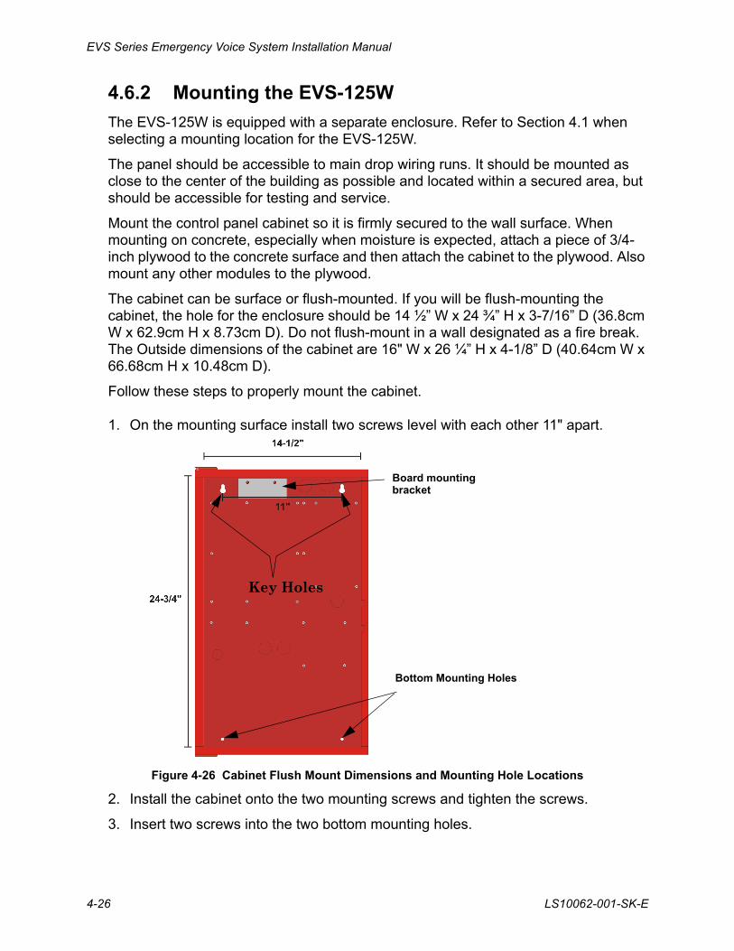
4.6.2 Mounting the EVS-125W
The EVS-125W is equipped with a separate enclosure. Refer to Section 4.1 when selecting a mounting location for the EVS-125W.
The panel should be accessible to main drop wiring runs. It should be mounted as close to the center of the building as possible and located within a secured area, but should be accessible for testing and service.
Mount the control panel cabinet so it is firmly secured to the wall surface. When mounting on concrete, especially when moisture is expected, attach a piece of 3/4-inch plywood to the concrete surface and then attach the cabinet to the plywood. Also mount any other modules to the plywood.
The cabinet can be surface or flush-mounted. If you will be flush-mounting the cabinet, the hole for the enclosure should be 14 ½” W x 24 ¾” H x 3-7/16” D (36.8cm W x 62.9cm H x 8.73cm D). Do not flush-mount in a wall designated as a fire break. The Outside dimensions of the cabinet are 16" W x 26 ¼” H x 4-1/8” D (40.64cm W x 66.68cm H x 10.48cm D).
Follow these steps to properly mount the cabinet.
1. On the mounting surface install two screws level with each other 11" apart.
Figure 4-26 Cabinet Flush Mount Dimensions and Mounting Hole Locations
2. Install the cabinet onto the two mounting screws and tighten the screws.
3. Insert two screws into the two bottom mounting holes.
Bottom Mounting Holes
Key Holes
Board mountingbracket
EVS Device Installation
LS10062-001-SK-E 4-27
4.6.3 Wiring Specifications
All wiring and devices installed in the system must meet the standards described in National Electrical Code (NFPA 70), NFPA Standard 72, and Life Safety Code (NFPA 101).
To avoid induced noise (transfer of electrical energy from one wire to another), keep input wiring isolated from high-current output and power wiring. Avoid pulling one multi-conductor cable for the entire panel.
Instead, separate the wiring as follows:
DO NOT pull wires from different groups through the same conduit.
For the same reasons, wiring within the cabinet should be routed around the perimeter of the cabinet. It should not cross the printed circuit board where it could induce noise into the sensitive microelectronics or pick up unwanted RF noise from the high speed circuits.
1/4” spacing must be maintained Input/Output Type: Wiring
between each of these circuit types;
Non Power-Limited: AC power, Standby batteries
as well as between power limited Power-Limited: SBUS, VBUS
and non power-limited circuits. Audio: Speaker
EVS Series Emergency Voice System Installation Manual
4-28 LS10062-001-SK-E
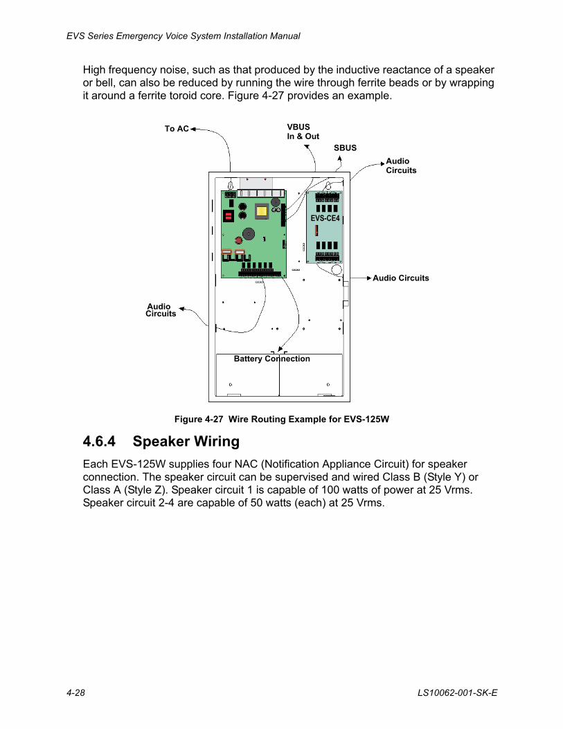
High frequency noise, such as that produced by the inductive reactance of a speaker or bell, can also be reduced by running the wire through ferrite beads or by wrapping it around a ferrite toroid core. Figure 4-27 provides an example.
Figure 4-27 Wire Routing Example for EVS-125W
4.6.4 Speaker Wiring
Each EVS-125W supplies four NAC (Notification Appliance Circuit) for speaker connection. The speaker circuit can be supervised and wired Class B (Style Y) or Class A (Style Z). Speaker circuit 1 is capable of 100 watts of power at 25 Vrms. Speaker circuit 2-4 are capable of 50 watts (each) at 25 Vrms.
To AC VBUSIn & Out
SBUS
AudioCircuits
Audio Circuits
AudioCircuits
Battery Connection
EVS-CE4

EVS Device Installation
LS10062-001-SK-E 4-29
4.6.4.1 Wiring Lengths
Note: The above table assumes a uniform distribution of the speakers, and that a max of 20% voltage drop on the last speaker is allowed.
Table 4-3 Wire Lengths
Number Of Speakers Total Load Wire Distance in Feet
@1/2 W @1 W Vrms Watts 18 AWG 16 AWG 14 AWG 12 AWG
10 5 25Vrms 5W 3900 6200 9860 15680
20 10 25Vrms 10W 2125 3380 5375 8540
30 15 25Vrms 15W 1460 2320 3690 5870
40 20 25Vrms 20W 1100 1750 2780 4420
52 26 25Vrms 26W 760 1200 1920 3050
80 40 25Vrms 40W 550 875 1390 2200
100 50 25Vrms 50W 450 715 1130 1800
150 75 25Vrms 75W 300 476 753 1200
200 100 25Vrms 100W 225 357 565 900
250 125 25Vrms 125W 180 285 452 720
EVS Series Emergency Voice System Installation Manual
4-30 LS10062-001-SK-E
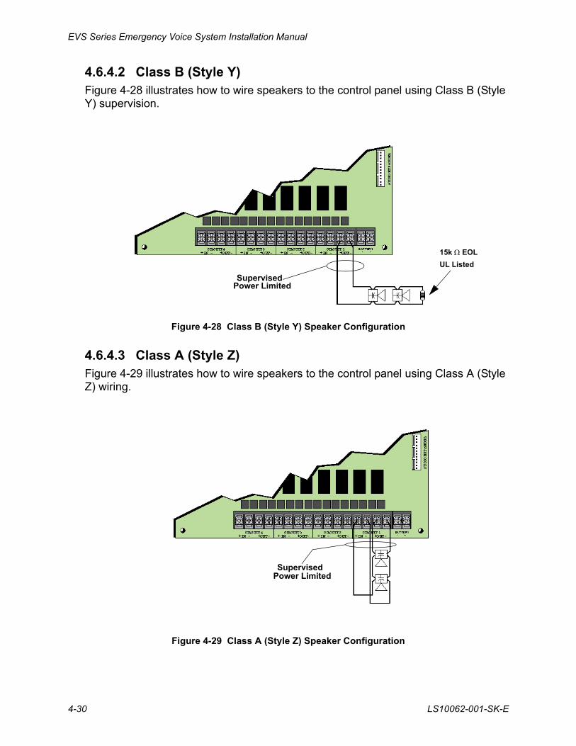
4.6.4.2 Class B (Style Y)Figure 4-28 illustrates how to wire speakers to the control panel using Class B (Style Y) supervision.
Figure 4-28 Class B (Style Y) Speaker Configuration
4.6.4.3 Class A (Style Z)Figure 4-29 illustrates how to wire speakers to the control panel using Class A (Style Z) wiring.
Figure 4-29 Class A (Style Z) Speaker Configuration
15k EOL
UL Listed
SupervisedPower Limited
SupervisedPower Limited
EVS Device Installation
LS10062-001-SK-E 4-31
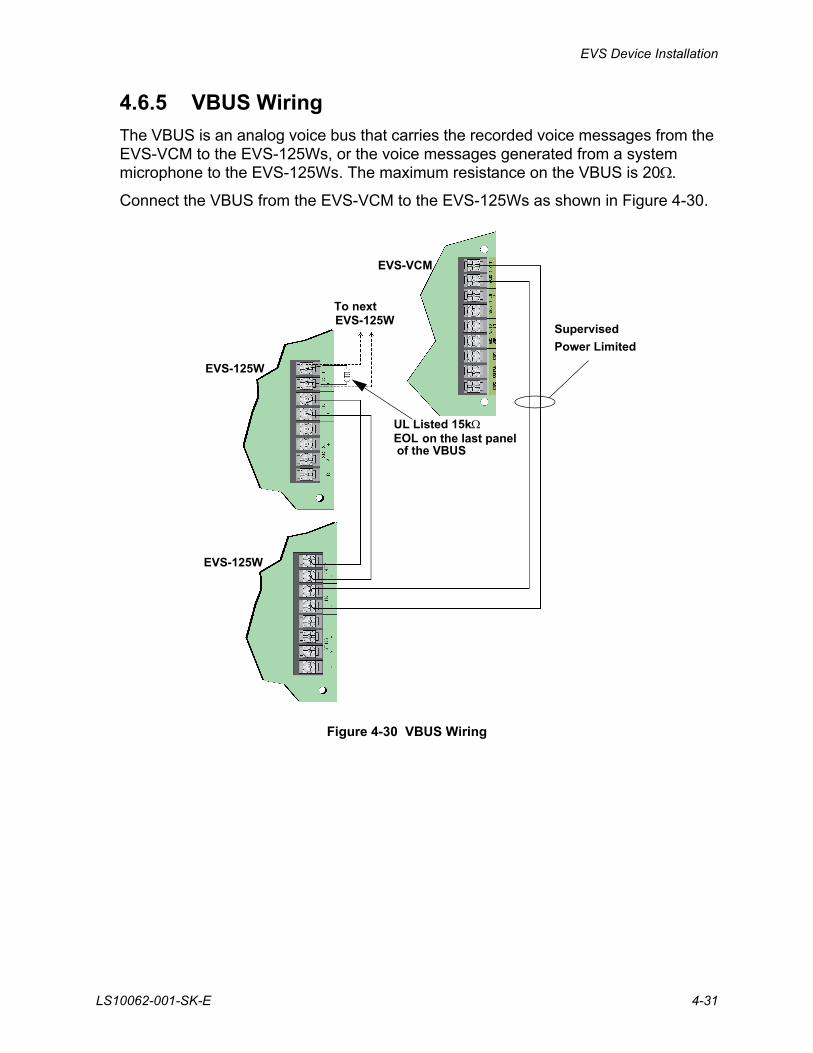
4.6.5 VBUS Wiring
The VBUS is an analog voice bus that carries the recorded voice messages from the EVS-VCM to the EVS-125Ws, or the voice messages generated from a system microphone to the EVS-125Ws. The maximum resistance on the VBUS is 20.
Connect the VBUS from the EVS-VCM to the EVS-125Ws as shown in Figure 4-30.
Figure 4-30 VBUS Wiring
UL Listed 15kEOL on the last panel
Supervised
Power Limited
EVS-VCM
EVS-125W
EVS-125W
To nextEVS-125W
of the VBUS
EVS Series Emergency Voice System Installation Manual
4-32 LS10062-001-SK-E
4.6.6 SBUS Wiring
This section contains information on how to connect EVS-125Ws (up to 4) onto the main control SBUS. Refer to Section 3.3 for SBUS specifications. Wire the SBUS as shown in Figure 4-31 or Figure 4-32.
Figure 4-31 SBUS Connections of the EVS-125W
Figure 4-32 Connecting Multiple EVS-125Ws to the SBUS
See Section 4.9 for information on setting SBUS addresses.
SupervisedPower Limited
Supervised
EVS-125W
EVS-VCM
EVS-125W
To next EVS-125W (Max 4)
Power Limited
EVS Device Installation
LS10062-001-SK-E 4-33
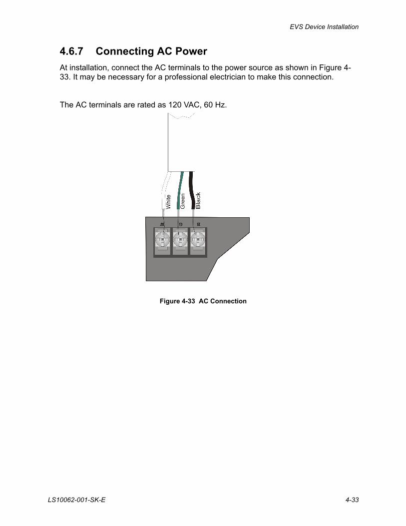
4.6.7 Connecting AC Power
At installation, connect the AC terminals to the power source as shown in Figure 4-33. It may be necessary for a professional electrician to make this connection.
The AC terminals are rated as 120 VAC, 60 Hz.
Figure 4-33 AC Connection
EVS Series Emergency Voice System Installation Manual
4-34 LS10062-001-SK-E
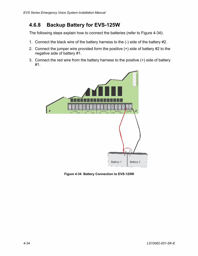
4.6.8 Backup Battery for EVS-125W
The following steps explain how to connect the batteries (refer to Figure 4-34):
1. Connect the black wire of the battery harness to the (-) side of the battery #2.
2. Connect the jumper wire provided form the positive (+) side of battery #2 to the negative side of battery #1.
3. Connect the red wire from the battery harness to the positive (+) side of battery #1.
Figure 4-34 Battery Connection to EVS-125W
EVS Device Installation
LS10062-001-SK-E 4-35
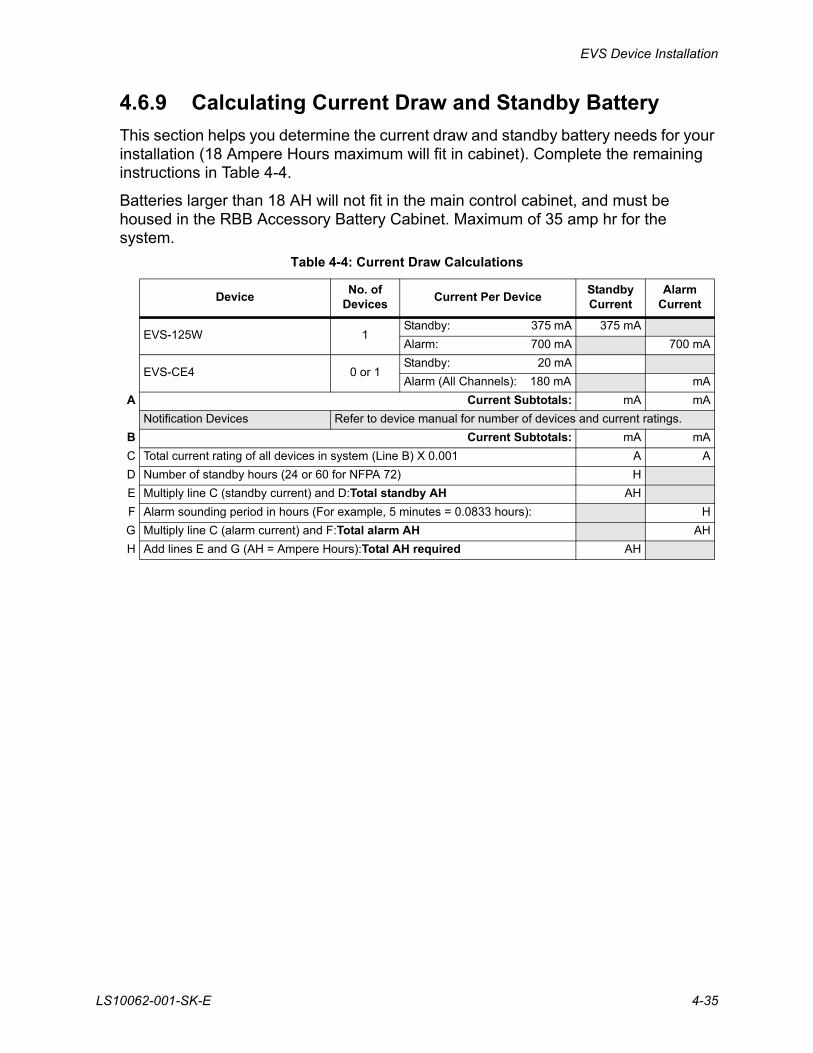
4.6.9 Calculating Current Draw and Standby Battery
This section helps you determine the current draw and standby battery needs for your installation (18 Ampere Hours maximum will fit in cabinet). Complete the remaining instructions in Table 4-4.
Batteries larger than 18 AH will not fit in the main control cabinet, and must be housed in the RBB Accessory Battery Cabinet. Maximum of 35 amp hr for the system.
Table 4-4: Current Draw Calculations
DeviceNo. of
DevicesCurrent Per Device
Standby Current
Alarm Current
EVS-125W 1Standby: 375 mA 375 mA
Alarm: 700 mA 700 mA
EVS-CE4 0 or 1Standby: 20 mA
Alarm (All Channels): 180 mA mA
A Current Subtotals: mA mA
Notification Devices Refer to device manual for number of devices and current ratings.
B Current Subtotals: mA mA
C Total current rating of all devices in system (Line B) X 0.001 A A
D Number of standby hours (24 or 60 for NFPA 72) H
E Multiply line C (standby current) and D:Total standby AH AH
F Alarm sounding period in hours (For example, 5 minutes = 0.0833 hours): H
G Multiply line C (alarm current) and F:Total alarm AH AH
H Add lines E and G (AH = Ampere Hours):Total AH required AH
EVS Series Emergency Voice System Installation Manual
4-36 LS10062-001-SK-E
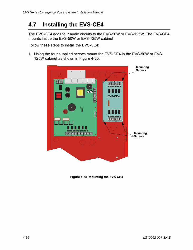
4.7 Installing the EVS-CE4
The EVS-CE4 adds four audio circuits to the EVS-50W or EVS-125W. The EVS-CE4 mounts inside the EVS-50W or EVS-125W cabinet
Follow these steps to install the EVS-CE4:
1. Using the four supplied screws mount the EVS-CE4 in the EVS-50W or EVS-125W cabinet as shown in Figure 4-35.
Figure 4-35 Mounting the EVS-CE4
MountingScrews
MountingScrews
EVS-CE4
EVS Device Installation
LS10062-001-SK-E 4-37
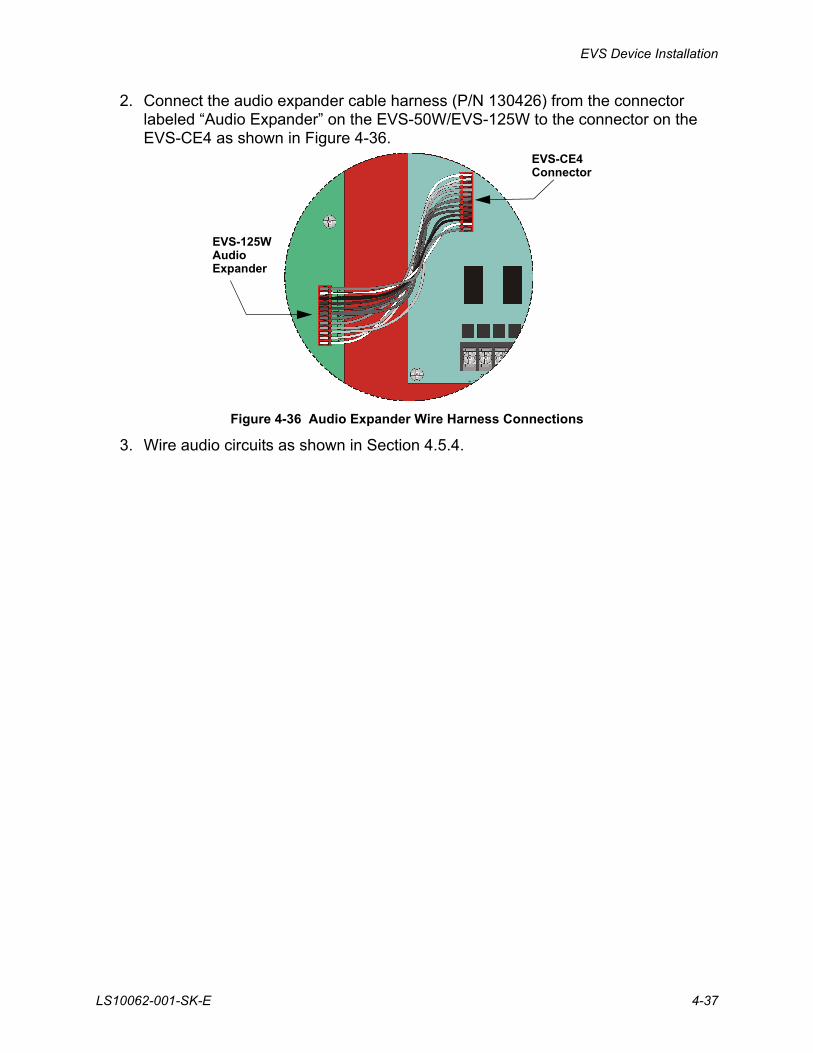
2. Connect the audio expander cable harness (P/N 130426) from the connector labeled “Audio Expander” on the EVS-50W/EVS-125W to the connector on the EVS-CE4 as shown in Figure 4-36.
Figure 4-36 Audio Expander Wire Harness Connections
3. Wire audio circuits as shown in Section 4.5.4.
EVS-CE4Connector
EVS-125WAudioExpander
EVS Series Emergency Voice System Installation Manual
4-38 LS10062-001-SK-E
4.8 Installing the EVS-RVM
The EVS-RVM Remote Voice Module is contained within the EVS-RCU Remote Command Unit. It provides a supervised microphone for live communication and an interface for the Emergency Voice System.
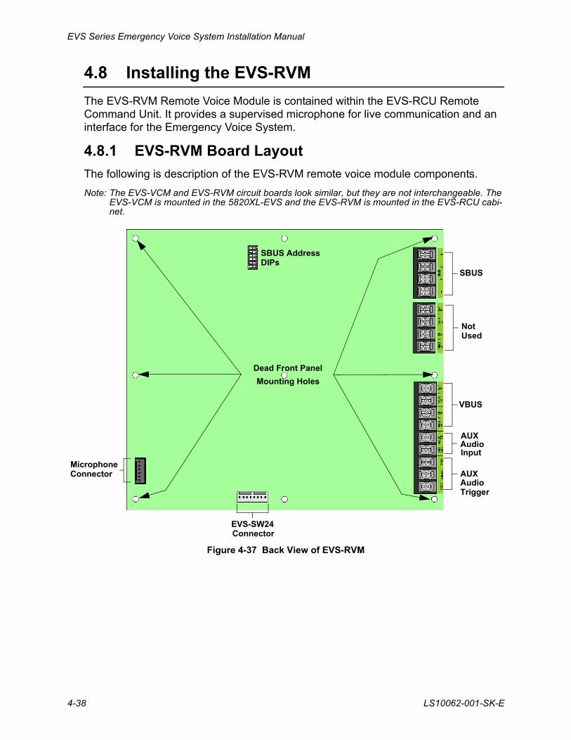
4.8.1 EVS-RVM Board Layout
The following is description of the EVS-RVM remote voice module components.
Note: The EVS-VCM and EVS-RVM circuit boards look similar, but they are not interchangeable. The EVS-VCM is mounted in the 5820XL-EVS and the EVS-RVM is mounted in the EVS-RCU cabi-net.
Figure 4-37 Back View of EVS-RVM
VBUS
MicrophoneConnector
SBUS AddressDIPs
AUX
Dead Front Panel
SBUS
AudioInput
AUXAudioTrigger
Mounting Holes
EVS-SW24 Connector
Not Used
EVS Device Installation
LS10062-001-SK-E 4-39
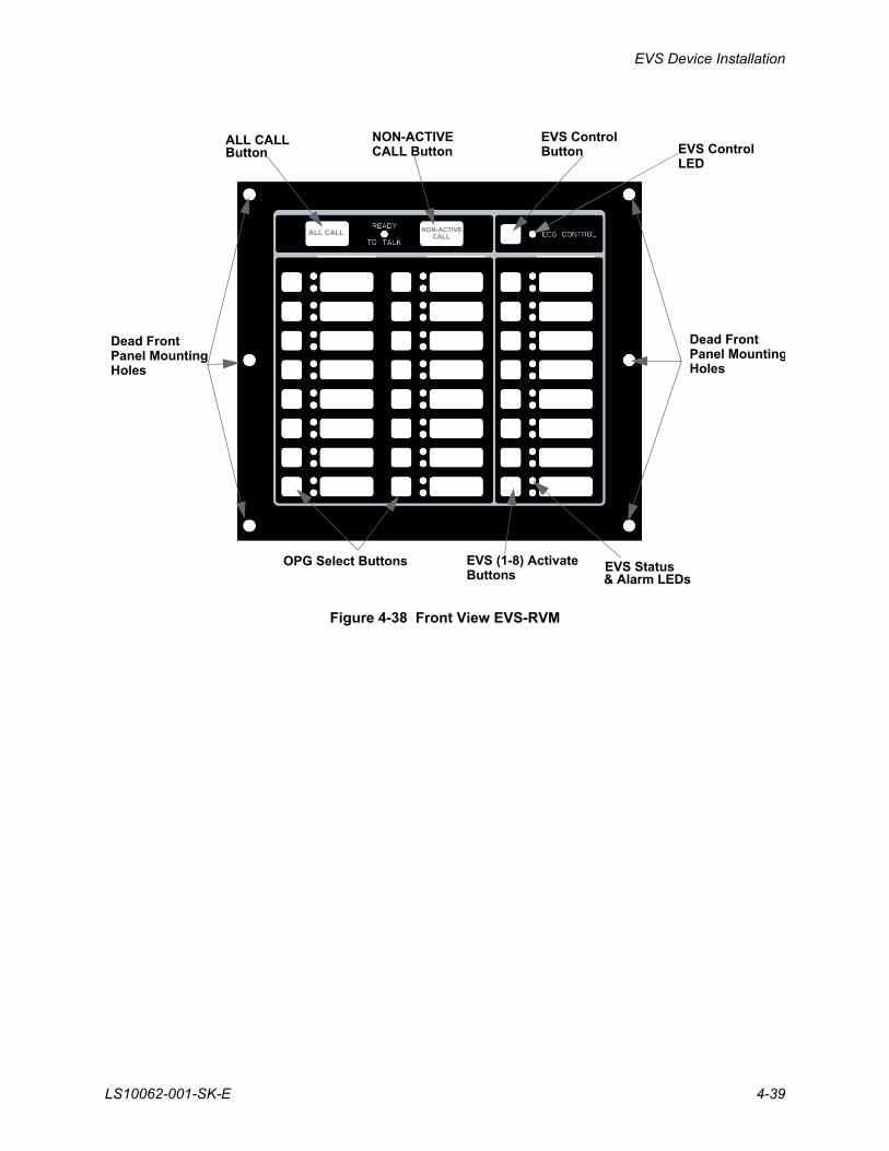
Figure 4-38 Front View EVS-RVM
Dead FrontPanel MountingHoles
Dead FrontPanel MountingHoles
OPG Select Buttons EVS (1-8) ActivateButtons
EVS Status
ALL CALLButton
NON-ACTIVE
& Alarm LEDs
EVS ControlButton EVS Control
LED
ALL CALL NON-ACTIVE CALL
CALL Button
EVS Series Emergency Voice System Installation Manual
4-40 LS10062-001-SK-E
4.8.2 Wiring the EVS-RVM
1. Refer to Figure 4-39 to properly connect the EVS-RVM to the FACPs SBUS.
Figure 4-39 SBUS Connections
2. See Section 4.9 to set SBUS addressing.
3. Connect the SBUS to the annunciator and EVS-RVM. See Figure 4-40.
Figure 4-40 SBUS Wiring for EVS-RVM
FACP
SupervisedPower Limited
EVS-RVM
From PreviousSBUS Device
Annunciator
EVS-RVM
EVS Device Installation
LS10062-001-SK-E 4-41
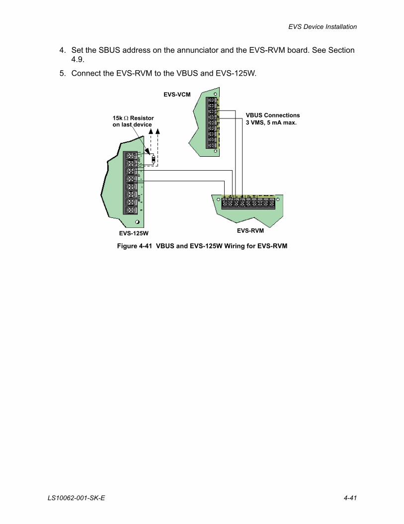
4. Set the SBUS address on the annunciator and the EVS-RVM board. See Section 4.9.
5. Connect the EVS-RVM to the VBUS and EVS-125W.
Figure 4-41 VBUS and EVS-125W Wiring for EVS-RVM
EVS-RVMEVS-125W
EVS-VCM
VBUS Connections3 VMS, 5 mA max.
15k Resistoron last device
EVS Series Emergency Voice System Installation Manual
4-42 LS10062-001-SK-E
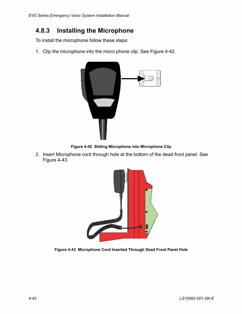
4.8.3 Installing the Microphone
To install the microphone follow these steps:
1. Clip the microphone into the micro phone clip. See Figure 4-42.
Figure 4-42 Sliding Microphone into Microphone Clip
2. Insert Microphone cord through hole at the bottom of the dead front panel. See Figure 4-43.
Figure 4-43 Microphone Cord Inserted Through Dead Front Panel Hole
EVS Device Installation
LS10062-001-SK-E 4-43
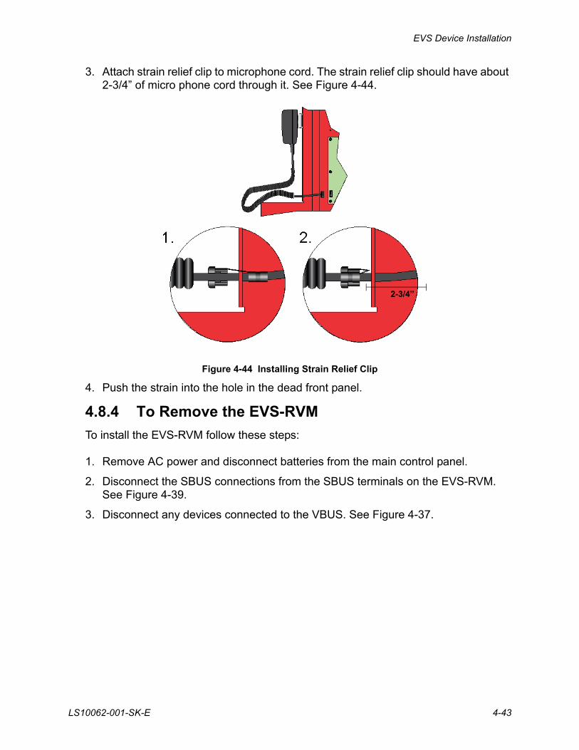
3. Attach strain relief clip to microphone cord. The strain relief clip should have about 2-3/4” of micro phone cord through it. See Figure 4-44.
Figure 4-44 Installing Strain Relief Clip
4. Push the strain into the hole in the dead front panel.
4.8.4 To Remove the EVS-RVM
To install the EVS-RVM follow these steps:
1. Remove AC power and disconnect batteries from the main control panel.
2. Disconnect the SBUS connections from the SBUS terminals on the EVS-RVM. See Figure 4-39.
3. Disconnect any devices connected to the VBUS. See Figure 4-37.
2-3/4”
EVS Series Emergency Voice System Installation Manual
4-44 LS10062-001-SK-E
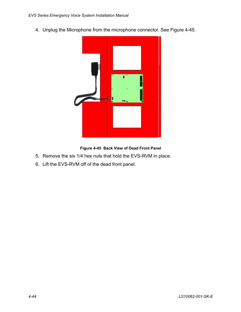
4. Unplug the Microphone from the microphone connector. See Figure 4-45.
Figure 4-45 Back View of Dead Front Panel
5. Remove the six 1/4 hex nuts that hold the EVS-RVM in place.
6. Lift the EVS-RVM off of the dead front panel.
EVS Device Installation
LS10062-001-SK-E 4-45
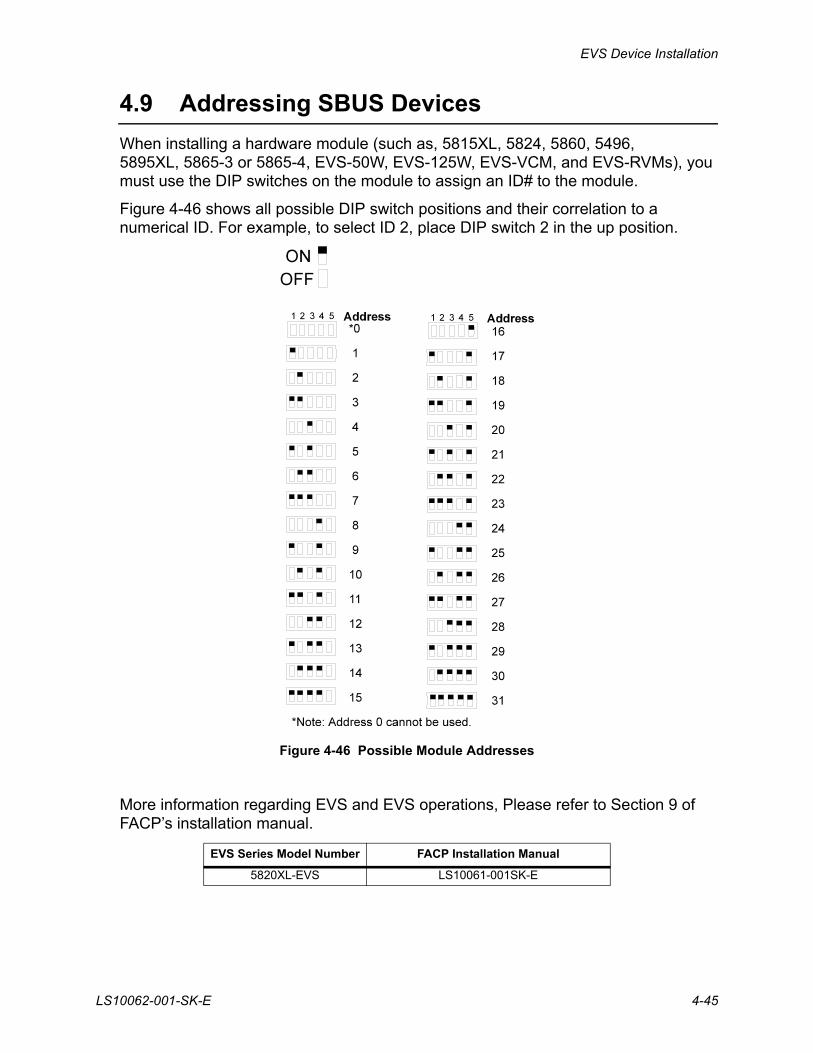
4.9 Addressing SBUS Devices
When installing a hardware module (such as, 5815XL, 5824, 5860, 5496, 5895XL, 5865-3 or 5865-4, EVS-50W, EVS-125W, EVS-VCM, and EVS-RVMs), you must use the DIP switches on the module to assign an ID# to the module.
Figure 4-46 shows all possible DIP switch positions and their correlation to a numerical ID. For example, to select ID 2, place DIP switch 2 in the up position.
Figure 4-46 Possible Module Addresses
More information regarding EVS and EVS operations, Please refer to Section 9 of FACP’s installation manual.
EVS Series Model Number FACP Installation Manual
5820XL-EVS LS10061-001SK-E

EVS Series Emergency Voice System Installation Manual
4-46 LS10062-001-SK-E

Silent Knight Fire Product Warranty and Return Policy
General Terms and Conditions• All new fire products manufactured by Silent Knight have a limited warranty period
of 36 months from the date of manufacture against defects in materials and workmanship. See limited warranty statement for details.
• This limited warranty does not apply to those products that are damaged due to misuse, abuse, negligence, exposure to adverse environmental conditions, or have been modified in any manner whatsoever.
Repair and RMA Procedure• All products that are returned to Silent Knight for credit or repair require a RMA
(Return Authorization) number. Call Silent Knight Customer Service at 800-328-0103 or 203-484-7161 between 8:00 A.M. and 5:00 P.M. EST, Monday through Friday to obtain a return authorization number.
• Silent Knight Technical Support is available at 800-446-6444 between 8:00 A.M. and 5:00 P.M. CST, Monday through Friday.
• All returns for credit are subject to inspection and testing at the factory before actual determination is made to allow credit.
• RMA number must be prominently displayed on the outside of the shipping box. See return address example under Advanced Replacement Policy.
• Included with each return should be: a packing slip that has the RMA number, a content list, and a detailed description of the problem.
• All products returned to Silent Knight must be sent freight pre-paid. After product is processed, Silent Knight will pay for shipping product back to customer via UPS ground.
• Return the Silent Knight product circuit board only. Products that are returned in cabinets will be charged an additional $50 to cover the extra shipping and handling costs over board only returns. Do not return batteries. Silent Knight has the authority to determine if a product is repairable. Products that are deemed un-repairable will be returned to the customer.
• Product that is returned that has a board date code more than 36 months from date of manufacture will be repaired and the customer will be assessed the standard Silent Knight repair charge for that model.
Advanced Replacement Policy• Silent Knight offers an option of advance replacement for fire product printed
circuit boards that fail during the first 6 months of the warranty period. These items must be returned with transportation charges prepaid and must be accompanied by a return authorization.
• For advance replacement of a defective board, contact your local Silent Knight distributor or call Silent Knight at 800-328-0103 to obtain a RMA (Return Authorization) number and request advanced replacement.
• A new or refurbished board will be shipped to the customer. The customer will initially be billed for the replacement board but a credit will be issued after the repairable board is received at Silent Knight. All returned products must comply with the guidelines described under “General Terms and Conditions” and “Repair and RMA Procedure”.
• The defective board must be returned within 30 days of shipment of replacement board for customer to receive credit. No credit will be issued if the returned board was damaged due to misuse or abuse.
• Repairs and returns should be sent to:Silent Knight / HoneywellAttn: Repair Department12 Clintonville RoadNorthford, CT 06472USA
RA Number:___________________

Manufacturer Warranties and Limitation of Liability
Manufacturer Warranties. Subject to the limitations set forth herein, Manufacturer warrants that the Products manufactured by it in its Northford, Connecticut facility and sold by it to its authorized Distributors shall be free, under normal use and service, from defects in material and workmanship for a period of thirty six months (36) months from the date of manufacture (effective Jan. 1, 2009). The Products manufactured and sold by Manufacturer are date stamped at the time of production. Manufacturer does not warrant Products that are not manufactured by it in its Northford, Connecticut facility but assigns to its Distributor, to extent possible, any warranty offered by the manufacturer of such product. This warranty shall be void if a Product is altered, service repaired by anyone other than Manufacturer or its authorized Distributors. This warranty shall also be void if there is a failure to maintain the Products and the systems in which they operate in proper working conditions.
MANUFACTURER MAKES NO FURTHER WARRANTIES, AND DISCLAIMS ANY AND ALL OTHER WARRANTIES, EITHER EXPRESSED OR IMPLIED, WITH RESPECT TO THE PRODUCTS,TRADEMARKS, PROGRAMS AND SERVICES RENDERED BY MANUFACTURER INCLUDING WITHOUT LIMITATION, INFRINGEMENT, TITLE, MERCHANTABILITY, OR FITNESS FOR ANY PARTICULAR PURPOSE. MANUFACTURER SHALL NOT BE LIABLE FOR ANY PERSONAL INJURY OR DEATH WHICH MAY ARISE IN THE COURSE OF, OR AS A RESULT OF, PERSONAL, COMMERCIAL OR INDUSTRIAL USES OF ITS PRODUCTS.
This document constitutes the only warranty made by Manufacturer with respect to its products and replaces all previous warranties and is the only warranty made by Manufacturer. No increase or alteration, written or verbal, of the obligation of this warranty is authorized. Manufacturer does not represent that its products will prevent any loss by fire or otherwise.
Warranty Claims. Manufacturer shall replace or repair, at Manufacturer's discretion, each part returned by its authorized Distributor and acknowledged by Manufacturer to be defective, provided that such part shall have been returned to Manufacturer with all charges prepaid and the authorized Distributor has completed Manufacturer's Return Material Authorization form. The replacement part shall come from Manufacturer's stock and may be new or refurbished. THE FOREGOING IS DISTRIBUTOR'S SOLE AND EXCLUSIVE REMEDY IN THE EVENT OF A WARRANTY CLAIM.
Warn-HL-08-2009.fm


Silent Knight12 Clintonville Road
Northford, CT 06472-1610203-484-7161
Fax: 203-484-7118
www.silentknight.com


![IoT-Based Proactive Energy Supply Control for Connected ... · which increases the production costs of EVs [1]. Thus, super-capacitor (SC) is utilized in EVs to support rapid discharging.](https://static.fdocuments.in/doc/165x107/5f2da76cd8bb4d203a2bbd4e/iot-based-proactive-energy-supply-control-for-connected-which-increases-the.jpg)