Horizontal Curves-Superelevation-And Geometric Design Standards

© AREMA 2015 1
Evaluation of the Potential Benefits of Superelevation for Mainline Turnouts in Heavy Axle Load Service
David Davis, P.E. Transportation Technology Center, Inc.
55500 DOT Rd Pueblo, CO 81001
Telephone: 719-584-0754 [email protected]
Rafael Jimenez Transportation Technology Center, Inc.
55500 DOT Rd Pueblo, CO 81001
Telephone: 719-584-0691 [email protected]
Muhammad Akhtar
Parsons Brinckerhoff Jeddah, Saudi Arabia [email protected]
WORD COUNT: 2951
ABSTRACT
Turnout alignment design is a complex problem, requiring consideration of technical, regulatory, and logistical issues. The railway goals of safety, reliability, and efficiency must all be met, while also maximizing the capacity of the line. New designs are usually required to fit in the footprint of the previously used turnouts, narrowing what can be accomplished to improve performance. In the same regard, the lengths of individual components such as switch points may also be limited by shipping or handling requirements of the railway.
As with the rest of the track, the allowable speed in a turnout curve is governed by the maximum cant deficiency limit in the Federal Railroad Administration track safety standards. For example, for an AREMA 24 curved point turnout, the maximum allowable speed is 62 mph (assuming 3 inches cant deficiency). AREMA designs are biased towards high allowable speeds by having a large closure curve radius at the expense of a large switch entry angle. However, higher peak lateral forces due to the alignment kink (entry) angle cause increased alignment degradation, increased lateral accelerations, reduced ride quality, and higher maintenance. Therefore, the speeds are normally restricted to about 40 mph through the turnouts. Thus, a turnout may have speed limits of 40 mph in the middle of 60 to 70 mph track.
In this project, the alignment of the typical AREMA-style turnout was modified to reduce lateral loads at switch points by reducing the entry angle. In the first modification, the entry angle was reduced by incorporating several circular curve segments of different radii. In addition, in the second modification, superelevation was incorporated in the diverging route by lowering the low rail. Dynamic vehicle simulations were conducted using NUCARS® (NUCARS® is a registered trademark of Transportation Technology Center, Inc., Pueblo, Colorado), and the results were compared with standard AREMA turnouts.
The results show that various types of vehicles can run through the diverging route of the turnouts at or very close to the maximum authorized speed of rest of the tangent track. Lateral to vertical (L/V) ratios were reduced significantly. Both modifications stay within the dimensions of the current standard AREMA 24 turnout.
A demonstration of this concept was conducted by modifying a number 20 turnout at the Facility for Accelerated Service Testing at the Transportation Technology Center in Pueblo, CO. Superelevation was added through the use of transition rails. Wheel/rail forces were measured before and after the addition of the superelevation.
INTRODUCTION
Turnout alignment design is a complex problem, requiring consideration of technical, regulatory, and logistical issues. The railway goals of safety, reliability, and efficiency must all be met while also maximizing the capacity of the line. New designs are usually required to fit in the footprint of the previously used turnouts, narrowing what can be accomplished to improve performance. In the same

© AREMA 2015 2
regard, the lengths of individual components such as switch points may also be limited by shipping or handling requirements of the railway.
The allowable speed through a turnout is often limited by the smallest radius curve in the turnout on the basis of cant deficiency or unbalanced superelevation (as is done with other curves on the railway). This limit caused designers of turnouts to optimize designs for allowable speed by using nontangential alignments, which has resulted in turnout designs that generate high lateral forces and the resultant degradation that follows.
This research reviewed potential alignments within the AREMA 24 turnout footprint to develop an improved performance turnout that would also have a higher allowable speed under the current cant deficiency rule.
As with the rest of the track, the allowable speed in a turnout curve is governed by the maximum cant deficiency limit in the Federal Railroad Administration (FRA) track safety standards. For example, for an AREMA 24 curved point turnout, the maximum allowable speed is 62 mph (assuming 3 inches cant deficiency) (1). AREMA designs are biased towards high allowable speeds by having a large closure curve radius at the expense of a large switch entry angle. However, higher peak lateral forces due to the alignment kink (entry) angle cause increased alignment degradation, increased lateral accelerations, reduced ride quality, and higher maintenance. Therefore, the speeds are normally restricted to about 40 mph through the turnouts. Thus, a turnout may have speed limits of 40 mph in the middle of 60 to 70 mph track.
In this project, the alignment of the standard AREMA turnout was modified to reduce lateral loads at switch points by reducing the entry angle. In the first modification, the entry angle was reduced by incorporating several circular curve segments of different radii. In addition, in the second modification, superelevation was incorporated in the diverging route by lowering the low rail. Dynamic vehicle simulations were conducted using NUCARS® (NUCARS® is a registered trademark of Transportation Technology Center, Inc., Pueblo, Colorado), and the results were compared with standard AREMA turnouts.
The results show that various types of trains can run through the diverging route of the turnouts at or very close to the design speed of the tangent track. Lateral to vertical (L/V) ratios were reduced significantly. Both modifications stay within the dimensions of the current standard AREMA 24 turnout.
BACKGROUND
As result of the strong partnership of railroad track engineers, trackwork suppliers, and researchers, turnout performance has improved significantly over the past 30 years. The improvement came largely through improved materials, quality control, maintainable designs, and new designs. However, turnouts are still major bottlenecks, requiring speed restrictions for diverging traffic.
The major cause of higher lateral loads is the entry angle of the switch. The entry angles have been reduced significantly using tangential and low entry angle alignments (2,3). Curve spirals and pseudo tangential designs have been used to minimize the increases in turnout length caused by low entry angle alignments. But, this is mostly limited to new tracks. In existing tracks, implementation of these designs is rather limited, because the new turnout must fit into an existing footprint due to track layout and/or switch machine and signal locations. Thus, such designs may be installed in new track, but not in existing tracks where the space is limited to AREMA standard lead length.
TURNOUT DESCRIPTION
Three turnout alignments of the same length were modeled for the purpose of this analysis:
AREMA 24 — 00 32’46” switch entry angle with two curve segments
Mod 24.1 — 00 09’16.21” switch entry angle with five curve segments
Mod 24.2 — 00 09’16.21” switch entry angle with five curve segments, partly superelevated to 1.0 inch.
Mod 24.1 has about one-third of the entry angle of the current AREMA 24 turnout. This reduction was achieved by reducing the switch and closure rail radius. The sum of the curve segments’ angles is equal

© AREMA 2015 3
to the frog angle. In Figure 1, each turnout begins at 50 feet and ends at 217 feet. A penalty for reduced entry angle is the shorter radius curve needed to complete the turnout. As a result, the maximum allowable speed (3 inches cant deficiency) is reduced from 62 mph for AREMA 24 alignment to 51 mph for Mod 24.1 alignment. A 1.0-inch superelevation was added to the diverging route for Mod 24.2 alignment, which increased the maximum speed limit to 59 mph.
Turnouts are installed without superelevation to simplify crosstie, plate work, and frog designs at the expense of greater cant deficiency. The outside rail of the sharpest curved segment was superelevated by 1.0 inch. The superelevation started just after the switch heel block, and it increased to 1.0 inch over a length of 31 feet. Superelevation remained uniform for some distance and finally ended a few feet before the point of tangency of the frog. This actual superelevation raised the maximum allowable speed to about 59 mph (Figure 2).
Figure 1. Turnout Geometry Figure 2. Turnout Superelevation
Vehicle Description
The following three vehicles, loaded and empty, were modeled on all three turnouts to simulate a wide range of North American railroad freight traffic:
Loaded hopper car (LH) – 263,000 pounds
Empty hopper car (EH) – 63,000 pounds
Loaded autorack (LAR) – 220,000 pounds
Empty autorack (EAR) – 68,000 pounds
Loaded tank car (LT) – 263,000 pounds
Empty tank car (ET) – 68,000 pounds
Based on experience, the longer (autorack) and rotationally stiffer (tank) cars are most likely to have performance issues negotiating turnouts.
Methodology
All three vehicles were modeled on all three turnouts at speeds ranging from 5 to 60 mph. Effects of lateral forces, vertical forces, L/V force ratio, and axle lateral movement (hunting) were studied. New 136RE rail and AAR1B wheels were used for this analysis. The results presented in this analysis are of the stated case scenario, but other wheel-rail conditions may produce different results.
Lateral Forces
Figure 3 shows the reduced entry angle effect on lateral forces of the leading wheel for all three turnouts under a loaded hopper car at 60 mph. A reduction in entry angle from 0.54 to 0.15 degree has resulted in three-fourths reduction in the lateral forces. The lateral peak force due to reduced entry angle of Mod 24.2 is about equal to the curving force at the sharpest curved segment. The data suggests that it might be

© AREMA 2015 4
possible to operate over the new design turnout at higher speeds while still benefitting from reduced wear and degradation.
Figure 3. Predicted Lateral Wheel Forces for Loaded Hopper at 60 mph
The reduced lateral peak force of the modified designs compared with the AREMA 24 design holds true over all modeled speeds for all vehicle types.
Similarly, the L/V force ratio for the modified designs is up to two-thirds lower than AREMA 24 design at various speeds. The L/V ratio is an indication of the propensity for rail rollover and flange climb. The modified turnout designs improve safety by reducing L/V ratio throughout the wide range of operating speeds. A 45 mph speed for loaded coal train operations through the AREMA 24 turnout corresponds to an L/V ratio of 0.35. TTCI’s experience with AREMA turnouts suggests the L/V ratio at this speed is acceptable. Modified turnouts can accommodate speeds up to 60 mph at half the perceived lower L/V ratio at a much lower wear rate.
Figure 4 is a summary of predicted maximum L/V ratio versus speed for the three turnout alignments (AREMA 24, Mod 24.1, and Mod 24.2) for the loaded autorack and loaded hopper cars.
Note: LAR = loaded autorack; LH = loaded hopper car
Figure 4. Predicted Maximum L/V vs. Speed for Three Turnout Alignments
Note that the two modified alignments produce similar dynamic performances and L/V ratios in the simulations conducted. The effect of adding superelevation is relatively minor on both lateral and vertical forces. The superelevation increases vertical forces in the closure curve as elevation is increased. Figure 5 shows vertical force versus distance for the outer wheel of the vehicle on the diverging route move. The outer wheel is climbing a ramp. From a vehicle dynamics perspective, it hits a “bump.” The lateral force increases due to the smaller radius curvature resulting from the spiral. Similarly, as the elevation ramps back down, the vertical force decreases. Lateral force decreases here as the second spiral radius increases.
© AREMA 2015 5
Figure 5. Predicted Vertical Wheel Force vs. Distance for Two Turnout Alignments
Additional review of the predicted dynamic performance of the modified turnout alignments suggests they will have stable vehicle behavior throughout the range of speeds allowed by the cant deficiency rule.
Field Test Under Heavy Axle Loads
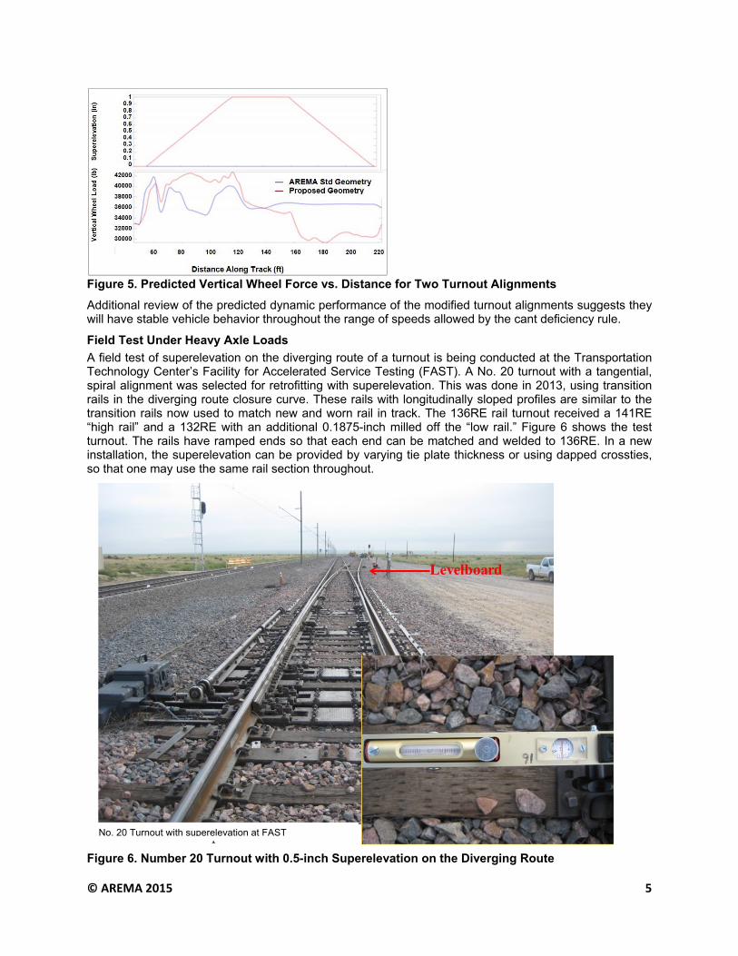
A field test of superelevation on the diverging route of a turnout is being conducted at the Transportation Technology Center’s Facility for Accelerated Service Testing (FAST). A No. 20 turnout with a tangential, spiral alignment was selected for retrofitting with superelevation. This was done in 2013, using transition rails in the diverging route closure curve. These rails with longitudinally sloped profiles are similar to the transition rails now used to match new and worn rail in track. The 136RE rail turnout received a 141RE “high rail” and a 132RE with an additional 0.1875-inch milled off the “low rail.” Figure 6 shows the test turnout. The rails have ramped ends so that each end can be matched and welded to 136RE. In a new installation, the superelevation can be provided by varying tie plate thickness or using dapped crossties, so that one may use the same rail section throughout.
Figure 6. Number 20 Turnout with 0.5-inch Superelevation on the Diverging Route
No. 20 Turnout with superelevation at FAST
© AREMA 2015 6
Field Test Results
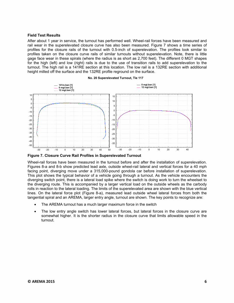
After about 1 year in service, the turnout has performed well. Wheel-rail forces have been measured and rail wear in the superelevated closure curve has also been measured. Figure 7 shows a time series of profiles for the closure rails of the turnout with 0.5-inch of superelevation. The profiles look similar to profiles taken on the closure curve rails of similar turnouts without superelevation. Note, there is little gage face wear in these spirals (where the radius is as short as 2,700 feet). The different 0 MGT shapes for the high (left) and low (right) rails is due to the use of transition rails to add superelevation to the turnout. The high rail is a 141RE section at this location. The low rail is a 132RE section with additional height milled off the surface and the 132RE profile reground on the surface.
Figure 7. Closure Curve Rail Profiles in Superelevated Turnout
Wheel-rail forces have been measured in the turnout before and after the installation of superelevation. Figures 8-a and 8-b show predicted lead axle, outside wheel-rail lateral and vertical forces for a 40 mph facing point, diverging move under a 315,000-pound gondola car before installation of superelevation. This plot shows the typical behavior of a vehicle going through a turnout. As the vehicle encounters the diverging switch point, there is a lateral load spike where the switch is doing work to turn the wheelset to the diverging route. This is accompanied by a larger vertical load on the outside wheels as the carbody rolls in reaction to the lateral loading. The limits of the superelevated area are shown with the blue vertical lines. On the lateral force plot (Figure 8-a), measured lead outside wheel lateral forces from both the tangential spiral and an AREMA, larger entry angle, turnout are shown. The key points to recognize are:
The AREMA turnout has a much larger maximum force in the switch
The low entry angle switch has lower lateral forces, but lateral forces in the closure curve are somewhat higher. It is the shorter radius in the closure curve that limits allowable speed in the turnout.
#20 Superelevated Turnout, Tie 117
-30 -20 -10 0 10 20 30 40 50
-50
-45
-40
-35
-30
-25
-20
-15
-10
-5
0
5
10
141re.ban [1]0 mgt.ban [1]12 mgt.ban [1]
-30 -20 -10 0 10 20 30 40
-35
-30
-25
-20
-15
-10
-5
0
5
10
15
0 mgt.ban [1]12 mgt.ban [1]
No. 20 Superelevated Turnout, Tie 117

© AREMA 2015 7
Figure 8-a. Typical Outside Rail Lateral Wheel/Rail Forces vs. Distance for a No. 20 Turnout with Fixed Point Frog – 40 mph Facing Point Diverging Move
Figure 8-b. Typical Outside Rail Vertical Wheel/Rail Forces vs. Distance for a No. 20 Turnout with Fixed Point Frog – 40 mph Facing Point Diverging Move
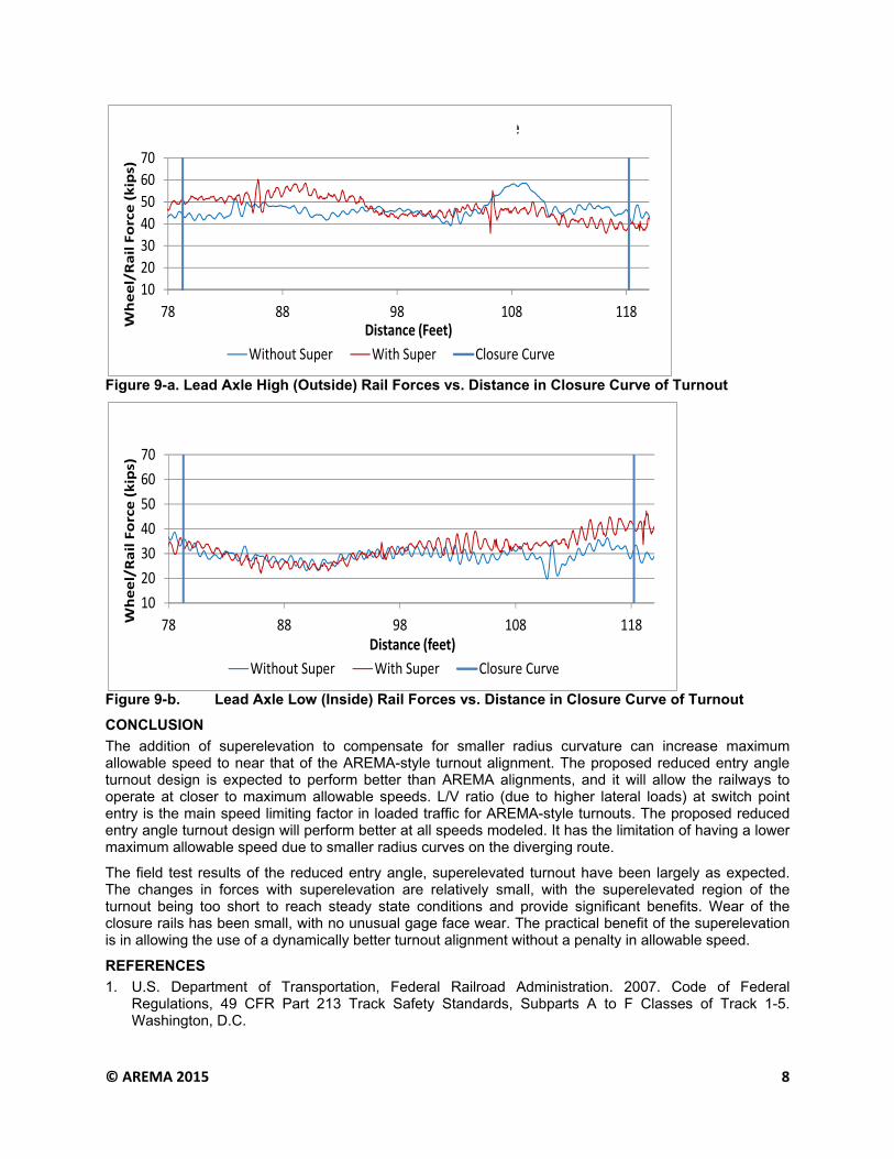
Figure 9-a and 9-b graphs show actual measured wheel-rail forces in the superelevated area of the turnout. Again, the limits of the 0.5-inch superelevation area are shown with the blue vertical lines. The ramps extend a few more feet on either end. Note that the outside wheel vertical force is higher for the superelevated turnout near the beginning of the elevated area (Figure 9-a). The modeling predicted this would occur as the wheels climb a longitudinal ramp. For the inside wheel, the opposite happens. It has higher vertical forces near the end of the superelevated zone as it starts to climb the low rail ramp that makes the track level again at the frog (Figure 9-b).
0
10
20
30
40
50
60
70
80
90
‐50 0 50 100 150 200
VER
TICAL FO
RCE (KIPS)
DISTANCE FROM P.O.S. (FT)
Low Entry Angle
© AREMA 2015 8
Figure 9-a. Lead Axle High (Outside) Rail Forces vs. Distance in Closure Curve of Turnout
Figure 9-b. Lead Axle Low (Inside) Rail Forces vs. Distance in Closure Curve of Turnout
CONCLUSION
The addition of superelevation to compensate for smaller radius curvature can increase maximum allowable speed to near that of the AREMA-style turnout alignment. The proposed reduced entry angle turnout design is expected to perform better than AREMA alignments, and it will allow the railways to operate at closer to maximum allowable speeds. L/V ratio (due to higher lateral loads) at switch point entry is the main speed limiting factor in loaded traffic for AREMA-style turnouts. The proposed reduced entry angle turnout design will perform better at all speeds modeled. It has the limitation of having a lower maximum allowable speed due to smaller radius curves on the diverging route.
The field test results of the reduced entry angle, superelevated turnout have been largely as expected. The changes in forces with superelevation are relatively small, with the superelevated region of the turnout being too short to reach steady state conditions and provide significant benefits. Wear of the closure rails has been small, with no unusual gage face wear. The practical benefit of the superelevation is in allowing the use of a dynamically better turnout alignment without a penalty in allowable speed.
REFERENCES
1. U.S. Department of Transportation, Federal Railroad Administration. 2007. Code of Federal Regulations, 49 CFR Part 213 Track Safety Standards, Subparts A to F Classes of Track 1-5. Washington, D.C.
10
20
30
40
50
60
70
78 88 98 108 118
Wheel/Rail Force (kips)
Distance (Feet)
High (Outside) Rail Forces ‐ Lead Axle
Without Super With Super Closure Curve
10
20
30
40
50
60
70
78 88 98 108 118Wheel/Rail Force (kips)
Distance (feet)
Low (Inside) Rail Forces ‐ Lead Axle
Without Super With Super Closure Curve

© AREMA 2015 9
2. Davis, David D., Matt Witte, Xinggao Shu, and Duane Otter. October 2012. “Turnout Alignments for Heavy Axle Load Mainline Traffic.” Technology Digest TD-12-021. Association of American Railroads, Transportation Technology Center, Inc., Pueblo, Colorado.
3. Otter, Duane, David Davis, and Stan Gurule. December 1996. “Geometry for an Improved Performance No. 20 Turnout.” Technology Digest TD-96-030. Association of American Railroads, Washington, D.C.
© AREMA 2015 10

© AREMA 2015 11
A R E M A 2 0 1 5 A N N U A L C O N F E R E N C E
Minneapolis, MN | October 4-7, 2015
Superelevation for TurnoutsBackground: Project Motivation
♦ Develop turnout alignment that optimizes performance and allowable speed● Requirements:
▲ Remain within current AREMA footprint (overall length)▲ Straight (tangent) frogs▲ Switch point lengths less than 65 feet
● Model simulations▲ Team of BNSF, Progress Rail Services and TTCI▲ Selected AREMA #24 turnout as base case▲ Reduced entry angle, spiral alignment─ Further added superelevation to compensate for smaller radius
curve
A R E M A 2 0 1 5 A N N U A L C O N F E R E N C E
Minneapolis, MN | October 4-7, 2015
R1 = Constant
R1 = ConstantR =∞
R = ∞
R = Spiral
Track Layout “101”
1) Circular Curve and Tangent
2) Add Transition Spiral
A R E M A 2 0 1 5 A N N U A L C O N F E R E N C E
Minneapolis, MN | October 4-7, 2015
R1 = Constant
R2 = ConstantR2 > R1
R = ∞
R = ∞
Turnout Layout “101”
1) Circular Curve and Tangent
2) Shorten Switch by Offsetting Alignments
Entry Angle
A R E M A 2 0 1 5 A N N U A L C O N F E R E N C E
Minneapolis, MN | October 4-7, 2015
Progress in Turnout Superstructure Design: Smoothing Alignments
♦ Under current rule:
– Maximize closure curve radius
• High entry angle and forces near point of switch
♦ Proposed:
– Balance entry and curving forces
• Pseudo-tangential
• Double spiral
– Add elevation to compensate for smaller radius
– Modify cant deficiency rule
A R E M A 2 0 1 5 A N N U A L C O N F E R E N C E
Minneapolis, MN | October 4-7, 2015
Optimized Turnout Alignment – Findings♦ Evaluation of designs and design elements which will minimize maximum lateral forces and life
cycle costs
♦ Entry angle: significant effect
– Pseudo-tangential alignments will provide significant benefit without lengthening switch
♦ Diverging alignment: spirals important for reducing accelerations
♦ Super elevation: minimal effect on net lateral forces. Will raise allowable speed under current rule by ~5-10 mph
0.46°
0.28°
Reduced wheel climb risk not reflected in speed limit
Allowable speed penalty (cant deficiency rule) 45 vs. 49 mph
A R E M A 2 0 1 5 A N N U A L C O N F E R E N C E
Minneapolis, MN | October 4-7, 2015
Superelevation for Turnouts• Turnout Alignment optimization (minimize forces/ allow
higher speeds)• Turnouts are the bottle neck of train traffic
– AREMA 24, max allowed ~ 62mph (3” cant deficiency rule)– Limited to 35-50 mph– High lateral loads at POS and car hunting
• Major cause is entry (kink) angle– Reduced by providing several segments of various radii
Degree of curvature
Distance along track ‐ feet
AREMA
Proposed

© AREMA 2015 12
A R E M A 2 0 1 5 A N N U A L C O N F E R E N C E
Minneapolis, MN | October 4-7, 2015
♦ Turnout Alignment optimization results – Tangential alignment (low entry angle switch) can reduce
lateral spike to force levels in closure curve
Superelevation for Turnouts
A R E M A 2 0 1 5 A N N U A L C O N F E R E N C E
Minneapolis, MN | October 4-7, 2015
Superelevation for Turnouts♦ Turnout Alignment optimization results – cont’d
– Adding superelevation:• Proposed geometry with 1” super – 61mph max• May increase maximum vertical forces
Distance along track ‐ feet
Vertical w
heel load
‐lbs
Superelevation‐Inches
A R E M A 2 0 1 5 A N N U A L C O N F E R E N C E
Minneapolis, MN | October 4-7, 2015
Background• May allow higher speeds by reducing cant deficiency• May allow use of better alignments• Will help re-balance loading high vs low rail
Superelevated Turnout
High Side 136RE (blue dash) to 141RE, Turnout Tie No. 123
Low Side 136RE (blue dash) to 132RE Milled, Turnout Tie No. 123
A R E M A 2 0 1 5 A N N U A L C O N F E R E N C E
Minneapolis, MN | October 4-7, 2015
Superelevated Turnout
#20 Turnout With Superelevation on HTL
Levelboard
136RE TO 141RE 136RE TO 132 WORN
A R E M A 2 0 1 5 A N N U A L C O N F E R E N C E
Minneapolis, MN | October 4-7, 2015
Superelevation for Turnouts
Typical Lateral and Vertical Force vs Distance plots for AREMA-style turnouts• Large lateral forces due to kink
and large entry angle
• Corresponding vertical load
• Relatively low steady state curving forces
0
10
20
30
40
50
60
70
80
90
‐50 0 50 100 150 200
VER
TICAL FO
RCE (KIPS)
DISTANCE FROM P.O.S. (FT)
Superelevated zone
A R E M A 2 0 1 5 A N N U A L C O N F E R E N C E
Minneapolis, MN | October 4-7, 2015
Superelevation for Turnouts
Close up view of measured forces in superelevatedsection of turnout• The effect of
superelevation on vertical forces is minimal
• Higher forces on upward ramps; lower forces on downward ramps
10
20
30
40
50
60
70
78 88 98 108 118Wheel/Rail Force (kips)
Distance (feet)
Low (Inside) Rail Forces ‐ Lead Axle
Without Super With Super Closure Curve
10
20
30
40
50
60
70
78 88 98 108 118
Wheel/Rail Force (kips)
Distance (Feet)
High (Outside) Rail Forces ‐ Lead Axle
Without Super With Super Closure Curve

© AREMA 2015 13
A R E M A 2 0 1 5 A N N U A L C O N F E R E N C E
Minneapolis, MN | October 4-7, 2015
Superelevation for Turnouts
• The effect of superelevation on vertical forces is minimal
• Higher forces on upward ramps; lower forces on downward ramps
10
20
30
40
50
60
70
78 88 98 108 118Wheel/Rail Force (kips)
Distance (feet)
Low (Inside) Rail Forces ‐ Lead Axle
Without Super With Super Closure Curve
10
20
30
40
50
60
70
78 88 98 108 118
Wheel/Rail Force (kips)
Distance (Feet)
High (Outside) Rail Forces ‐ Lead Axle
Without Super With Super Closure Curve
A R E M A 2 0 1 5 A N N U A L C O N F E R E N C E
Minneapolis, MN | October 4-7, 2015
Superelevated Turnout
• Wear of the machined rails has been minimal to date.
A R E M A 2 0 1 5 A N N U A L C O N F E R E N C E
Minneapolis, MN | October 4-7, 2015
Superelevated Turnout
Comparison of Worn Rail Shapes with and without Superelevation in Closure Curve (FAST HTL)
High Rail, 108 ft from Point of Switch
-40 -30 -20 -10 0 10 20 30 40
-50
-45
-40
-35
-30
-25
-20
-15
-10
-5
0
5
10
-30 -20 -10 0 10 20 30 40 50
-50
-45
-40
-35
-30
-25
-20
-15
-10
-5
0
5
10#20 Turnout, no super elevation, 96 MGT #20 Turnout, with super elevation, 59 MGT
A R E M A 2 0 1 5 A N N U A L C O N F E R E N C E
Minneapolis, MN | October 4-7, 2015
Superelevated Turnout
Comparison of Worn Rail Shapes with and without Superelevation in Closure Curve (FAST HTL)
Low Rail, 108 ft from Point of Switch
-40 -30 -20 -10 0 10 20 30 40
-50
-45
-40
-35
-30
-25
-20
-15
-10
-5
0
5
10
-40 -30 -20 -10 0 10 20 30 40 50
-50
-45
-40
-35
-30
-25
-20
-15
-10
-5
0
5
10#20 Turnout, no super elevation, 96 MGT #20 Turnout, with super elevation, 59 MGT
A R E M A 2 0 1 5 A N N U A L C O N F E R E N C E
Minneapolis, MN | October 4-7, 2015
Superelevation for TurnoutsSummary:♦ Traditional turnout alignment design produced robust designs
that were biased towards providing a high allowable speed based on closure curve radius
♦ Low entry angle, spiral designs perform better dynamically● Have an allowable speed penalty due to smaller radius closure curve● May inhibit implementation
♦ Adding superelevation to diverging route● Vehicle – Track dynamic simulation suggests that the effect on forces
will be relatively small● Would enable railways to use better turnout alignments without an
allowable operating speed penalty
A R E M A 2 0 1 5 A N N U A L C O N F E R E N C E
Minneapolis, MN | October 4-7, 2015
Superelevation for TurnoutsSummary:♦ A tangential, spiral alignment number 20 turnout was retrofit
with ½ inch of superelevation in diverging route● Done with transition rails on the existing platework● Would be done with platework and same section rail on new
installations
♦ Initial Performance● Dynamic effects: superelevation seen as a “small bump” by train● Closure curve rail wear similar to flat turnouts

© AREMA 2015 14
A R E M A 2 0 1 5 A N N U A L C O N F E R E N C E
Minneapolis, MN | October 4-7, 2015
Evaluation of the Potential Benefits of Superelevation for
Mainline Turnouts in Heavy Axle Load Service
David Davis, Rafael Jimenez and Muhammad Akhtar