ETP O S IV R N Ulis · 2020-01-16 · two instruments. 1! WARNING ! The Ulis screws are color coded...
24
Ulis SURGICAL TECHNIQUE SPINAL POSTERIOR FIXATION SYSTEM D E G E N E R A T I V E P O S T E R I O R F I X A T I O N
Transcript of ETP O S IV R N Ulis · 2020-01-16 · two instruments. 1! WARNING ! The Ulis screws are color coded...

Ulis TABLE OF CONTENT 1
Ulis
SURGICAL TECHNIQUE
SPINAL POSTERIOR FIXATION SYSTEM
DEG
EN
ERA
TIVE POSTERIO
R FIXA
TIO
N


Ulis TABLE OF CONTENT 1
SURGICAL STEPS
REFERENCES
I Patient preparation 02. . . . . . . . . . . . . .. .II Pedicle preparation & screw selection 02. .. .III Tapping 04. . . . . . . . . . . . . . . . . . . . .. .IV Screw insertion 05. . . . . . . . . . . . . . . . .. .V Rod preparation & handling 06. .VI Rod reduction & setscrew insertion 07. . .. .VII Correction maneuvers 10. . . . . . . . . . . .. .VIII Final tightening 12. . . . . . . . . . . . . . . .. .
13. . . . . . . . . . . . . . . . . . .. .1 Instruments
17. . . . . . . . . . . . . . . . . . . . .. .2 Implants
. . . . . . . .

Ulis SURGICAL TECHNIQUE2
I
II
PATIENT PREPARATION
PEDICLE PREPARATION & SCREW SELECTION
The patient is placed on the operating room table using the standard position indicated for posterior fixation placement.
X-ray shall be used during the entire procedure: to confirm identification of the affected disc, good positioning of the screws and the final position of the whole assembly.
Square AwlU1-A121N1
Mark the affected segment after c-arm control. Perform the incision over the levels on which the screws must be inserted.
Once the different structures (facets, pedicles and processes) have been exposed, locate the entry point for screws on the pedicle and perforate the cortical bone using the square awl U1‑A121N1.

Ulis SURGICAL TECHNIQUE 3
Lumbar SpatulaU1-A127
Curved Lumbar Spatula U1-A127C
Straight Lenke Probe U1-A128S
Lenke ProbeU1-A128
To create a pathway for screws in the pedicle, use the different pedicle probes available depending on surgeon’s practice: lumbar spatula U1‑A127, lenke probe U1‑A128, curved lumbar spatula U1‑A127C or the straight lenke probe U1‑A128S.
The appropriate lenght and depth for each vertebra are estimated by the surgeon.
The integrity of the intrapedicular cancellous bone can be checked with the pedicle probe with ball tip U1‑A124N1 by letting it slide on the pilot hole’s wall.
The lenght of the screw to be inserted can be determined by putting the tip of the pedicle probe at the bottom of the hole and then marking the lenght of the inserted intrapedicular part with a finger at the pedicle’s surface.
Pedicle probe with ball tipU1-A124N1

Ulis SURGICAL TECHNIQUE4
III TAPPING
1
2
To connect a sharp tap U1‑A13XS to the ratcheting cylindrical handle SD‑A411ALSH or T-handle SD‑A411ATSH, pull the ring of the handle towards the silicon part.
While maintaining this position, insert the square tip of the sharp tap into the handle and release the ring to secure the connection between the two instruments.
1
2
! WARNING !The Ulis screws are color coded according their diameters. It is mandatory to use the tap corresponding to the screw diameter.
Always double check the connection of the two pieces before giving it to the surgeon.
IS2-MXXXT: Multiaxial screwIS2-MRXXXT: Reduction screwIS2-SXXXT: Monoaxial screw
X= DiameterXX= LenghtEx: IS2-M645T Ø6,5 & 45 mm
Sharp TapsU1-A13XS
Ø 4,5 mm Ø 5,5 mm Ø 6,5 mm Ø 7,5 mm Ø 8,5 mm
U1-A134S U1-A135S U1-A136S U1-A137S U1-A138S
Cannulated ratcheting cylindrical handleSD-A411ALSH Cannulated ratcheting T-handle
SD-A411ATSH
Ulis SURGICAL TECHNIQUE 5
1
3
2
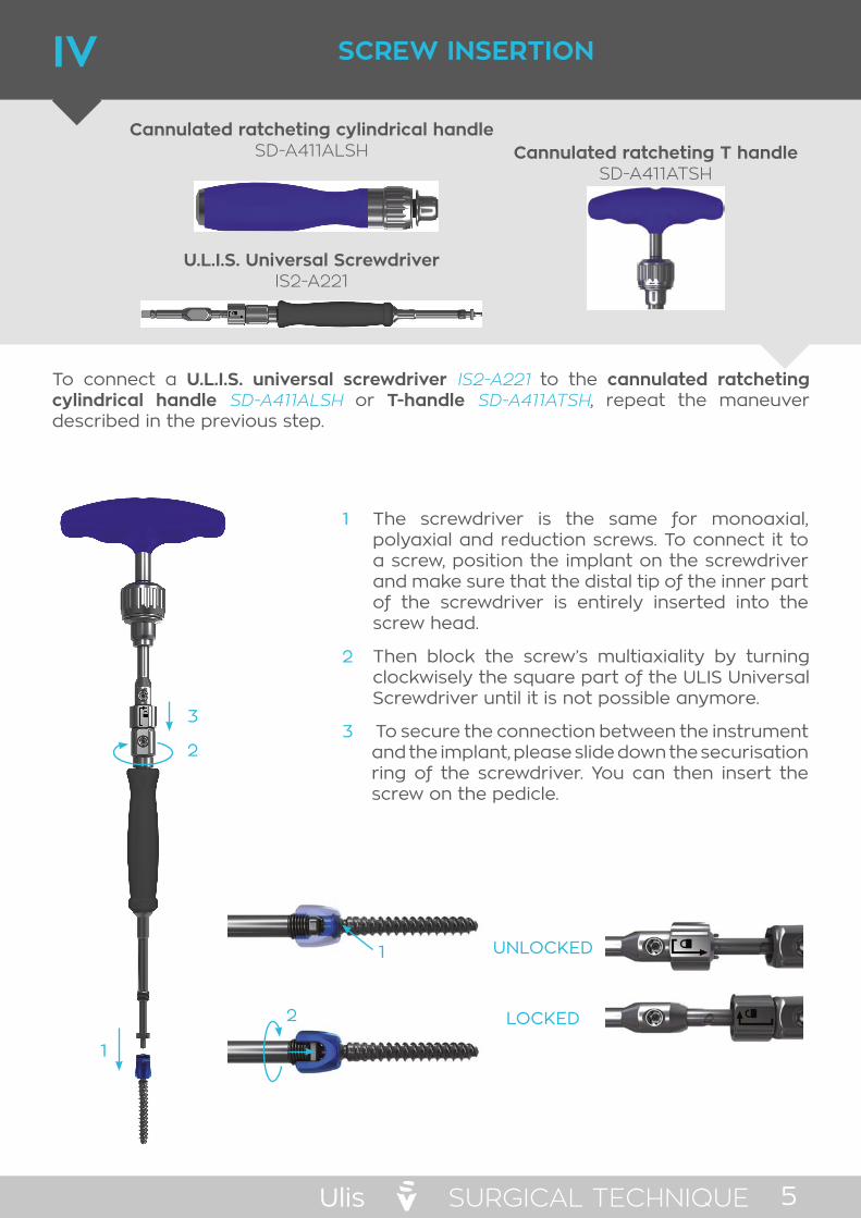
IV SCREW INSERTION
Cannulated ratcheting cylindrical handleSD-A411ALSH
U.L.I.S. Universal ScrewdriverIS2-A221
Cannulated ratcheting T handleSD-A411ATSH
To connect a U.L.I.S. universal screwdriver IS2‑A221 to the cannulated ratcheting cylindrical handle SD‑A411ALSH or T-handle SD‑A411ATSH, repeat the maneuver described in the previous step.
The screwdriver is the same for monoaxial, polyaxial and reduction screws. To connect it to a screw, position the implant on the screwdriver and make sure that the distal tip of the inner part of the screwdriver is entirely inserted into the screw head.
Then block the screw’s multiaxiality by turning clockwisely the square part of the ULIS Universal Screwdriver until it is not possible anymore.
1
2
To secure the connection between the instrument and the implant, please slide down the securisation ring of the screwdriver. You can then insert the screw on the pedicle.
3
1
2 LOCKED
UNLOCKED

Ulis SURGICAL TECHNIQUE6
V ROD PREPARATION & HANDLING
To discconnect a U.L.I.S. universal screwdriver IS2‑A221 from the screw when fully inserted:
Unlock the securisation ring by slinding it up on the screwdriver shaft.
Then disconnect the screwdriver from the screw by turning the square part unclockwisely.
1
2
The ULIS universal Screwdriver can then be removed and this step repeated to insert as many screw as needed.
French BenderU1-A321
The ULIS system offers a large range of prebent rods from 30 mm up to 120 mm MS1‑R6XXXCT.
The system can also be used with straight rigid rod L2‑R6XXHT or Co-Cr rigid rod U1‑R625HC which can be contoured at the desired curvature with the french bender U1‑A321.
The prepared rod can then be handled and inserted using the rod holder U1‑A214S.
12
Rod HolderU1-A214S
! WARNING !While inserting the screw in the pedicle, take care not to grip the screwdriver shaft above or below the black sleeve

Ulis SURGICAL TECHNIQUE 7
To adjust the screws depth or to align the screw heads for monobloc screws, use the screw adjuster MS1‑A222.
When the screw heads are aligned, insert the rod in the implant saddles using the rod holder U1‑A214S. Then place the setscrew using the setscrew holder MS1‑A231.
To load a setscrew MS1‑L100T on the setscrew holder :
Pull up the trigger of the setscrew holder.
Finally release the trigger of the setscrew holder.
While maintaining this position, slide the tip of the instruments in the «star» footprint of the setscrew.
1
2
3 1
2
3
! WARNING !Never use the setscrew holder MS1-A231 for the final tightening.
12
VI ROD REDUCTION & SETSCREW INSERTION
Screw AdjusterMS1-A222
Setscrew HolderMS1-A231
! WARNING !If using the Flex+2 rods for dynamic stabilization or protection of the adjacent level, it is mandatory not to bend it on the flexible part.
Never bend the Flex+2 rods above the transversal laser mark
The Ulis system offers three options to persuade the rod : Rod pusher Persuader Reduction screws

Ulis SURGICAL TECHNIQUE8
1
2
If a more powerful reduction is needed, use the persuader IS1‑A317 and the inner tube for persuader IS1-A316.
To position the persuader on the screw head:
Squeeze the flanges toward the tube to open the persuader at its distal end.
1
Slide down the persuader on the screw head.
2
Release the flanges to connect the persuader to the screw.
3
OPTION B
PersuaderIS1-A317
Inner Tube for PersuaderIS1-A316
Repeat this step on all screws prior to apply correction maneuvers
While maintaining the rod in the implant saddle with the rod pusher, engage partially the setscrew in the screw head and turn clockwisely to thread it
Once the setscrew is in position, pull up the wing of the setscrew holder to release the connection and remove the setscrew holder.
1
2
Use the rod pusher U1‑A224 to push the rod in the screw head prior to the setscrew insertion.
OPTION ARod Pusher
U1-A224
1 2 3

Ulis SURGICAL TECHNIQUE 9
Once the persuader is positionned on the screw head, persuade the rod thanks to the inner tube for persuader IS1‑A316:
Slide the inner tube into the persuader in place.
1 Once the threaded part of the inner tube comes in contact with the superior edge of the persuader, begin screwing to reduce the rod in the implant saddle.
2
Once the setscrew reaches the top of the screw head, turn Clockwisely to load it on the screw and secure the rod.
3
With the setscrew in position, pull up the wing of the setscrew holder to release the connection and remove the setscrew holder.
4
Remove the inner shaft for persuader by unscrewing it and sliding it up from the persuader. Then squeeze the persuader’s flanges to disconnect it from the screw head.
5
21
4
3
5
Repeat these steps on all screws prior to apply correction maneuvers.
To insert the setscrew when the rod is completely seated in the implant saddle, load a setscrew on the setscrew holder as described above and slide down the assembly through the inner shaft for persuader.

Ulis SURGICAL TECHNIQUE10
3
2
1
OPTION C
VII CORRECTION MANEUVERS
ROTATION OF THE RODRod Gripper
U1-A216 Open Rod Rotation WrenchU1-A344N1
After all setscrew’s placement, the rod can be rotated with the rod gripper U1‑A216.
1
2
3
Strongly grip the rod in the instrument’s jaw
Rotate the rod to give a normal curvature in the sagittal plan.
Release the grip by pushing the button on the rack and pinion.
1 2 3
Setscrew HolderMS1-A231
Tab RemoverIS2-A421
T30 ShaftMS1-A411
Reduction screws IS2‑MRXXXT can also be used to help in rod reduction. The most convenient is to place reduction screws in the middle of the construct where spondylolisthesis reduction is often needed.
Engage the setscrew in the reduction screw’s extended tabs using the setscrew holder or the T30 shaft MS1‑A411 and turn clockwisely to screw it and reduce the rod.
1
Once the rod reaches the bottom of the implant saddle, disconnect the setscrew holder by pulling the wing up and removing it.
2
To break the extended tabs after the rod persuasion and setscrew tightening, use the tab remover IS2‑A421. Close the jaw on the extension and break it.
3
Introduce the rod in all screw heads and load a setscrew on the setscrew holder:

Ulis SURGICAL TECHNIQUE 11
When using the straight rigid rod L2‑R6XXHT or Co-Cr rigid rod U1‑R625HC, grab the hexagonal end of the rod thanks to one or the other side of the open rod rotation wrench U1‑A344N1 and use it to rotate the rod.
DISTRACTION & COMPRESSION
DistractorU1-A342
Dual Axis CompressorU1-A343
To adjust the restored disc height or the curvature of the spine, a distractor U1‑A342 and a dual axis compressor U1‑A343 are available.
To distract: lock the setscrew on the screw used as « reference », place the jaw of the distractor as shown on the picture and distract by squeezing the handles. Lock the untightened setscrew when the desired distraction is obtained.
1
To compress: lock the setscrew on the screw used as « reference », place the jaw of the compressor as shown on the picture and compress by squeezing the handles. Lock the untightened setscrew when the desired compression is obtained.
2
IN SITU BENDING
If additional correction of the curvature in the sagittal plane is needed, use the right/left sagittal bender U1‑A328/U1‑A329 as shown besides.
1
2
Right Sagittal BenderU1-A328
Left Sagittal BenderU1-A329
Ulis SURGICAL TECHNIQUE12
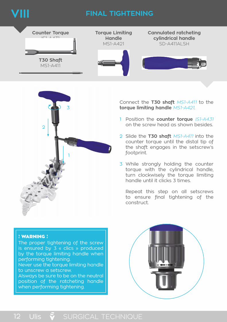
VIII FINAL TIGHTENING
Counter TorqueIS1-A431
T30 ShaftMS1-A411
Torque Limiting Handle
MS1-A421
Cannulated ratcheting cylindrical handle
SD-A411ALSH
! WARNING !The proper tightening of the screw is ensured by 3 « clics » produced by the torque limiting handle when performing tightening. Never use the torque limiting handle to unscrew a setscrew.Alsways be sure to be on the neutral position of the ratcheting handle when performing tightening.
Connect the T30 shaft MS1‑A411 to the torque limiting handle MS1‑A421.
Position the counter torque IS1‑A431 on the screw head as shown besides.
Slide the T30 shaft MS1‑A411 into the counter torque until the distal tip of the shaft engages in the setscrew’s footprint.
While strongly holding the counter torque with the cylindrical handle, turn clockwisely the torque limiting handle until it clicks 3 times.
Repeat this step on all setscrews to ensure final tightening of the construct.
1
2
3
1
2
3

Ulis REFERENCE 13
Square Awl U1-A121N1
Lumbar Spatula U1-A127
Curved Lumbar Spatula U1-A127C
Lenke Probe U1-A128
Straight Lenke Probe U1-A128S
Sharp Tap U1-A13XS
Pedicle Probe with ball Tip U1-A124N1
U.L.I.S. Universal Screwdriver IS2-A221
Screw Adjuster MS1-A222
INSTRUMENTSI

Ulis14
Screw Removal Instrument IS2-A420
French Bender U1-A321
Open Rod Rotation Wrench U1-A344N1
Rod Holder U1-A214S
Setscrew Holder MS1-A231
T30 Shaft MS1-A411
Rod Pusher U1-A224
Persuader IS1-A317
Inner Tube for Persuader IS1-A316
Rod Gripper U1-A216
REFERENCE

Ulis REFERENCE 15
Dual Axis Compressor U1-A343
Distractor U1-A342
Right Sagittal Bender U1-A328
Left Sagittal Bender U1-A329
Tab Remover Tab Remover
Cannulated Ratchteing T-Handle SD-A411TSH
Cannulated Ratcheting Cylindrical Handle SD-A411LSH
Torque Limiting Handle MS1-A421

Ulis16
Ulis Screws Rack SD-RACK 1
Tray 5 ULIS IS1-TRAY115
Pedicular Preparation Tray SD-TRAY111
Tray 1 ULIS IS1-TRAY111
Tray 2 ULIS IS1-TRAY112
Tray 4 ULIS IS1-TRAY114
SV Common Base SD-BASE1168
SV Common Base(2 levels) SD-BASE11117
SV Common Lid SD-LID11
REFERENCE

Ulis REFERENCE 17
IMPLANTSII
COLOR CODED DIAMETERS
Ø 4,5 mm Ø 5,5 mm Ø 6,5 mm Ø 7,5 mm Ø 8,5 mm
SCREWS RANGE
Ø/L 25 30 35 40 45 50 55 60 70 80 90
4.5
5.5
6.5
7.5
8.5
IS2-MXXXT: Multiaxial screwIS2-SXXXT: Monoaxial screw
X= DiameterXX= LenghtEx: IS2-M645T: Ø6,5 & 45 mm
MULTIAXIAL & MONOAXIAL SCREWS
Ø/L 25 30 35 40 45 50 55 60
5.5
6.5
7.5
IS2-MRXXXT: Reduction screw X= DiameterXX= Lenght
REDUCTION SCREWS

Ulis18
ROD RANGE
Length
MS1-R6XXXCT L2-R6XXCHT L2-R6XXCHT U1-R6XXHC
Prebent Percutaneous Rod
Prebent Rod with Hexagonal End
Straight Rod with Hexagonal End
Chromium Cobalt Straight Rod
TiA6V TiA6V TiA6V Co-Cr
30
35
40
45
50
55
60
65
70
75
80
85
90
95
100
110
120
130
140
150
REFERENCE

Ulis 19NOTES
NOTES

Ulis20 NOTESNOTES
NOTES


See package insert for labeling limitation
Non contractual document GIS2-ST_06GB
Distributed by SPINEVISION
10 Rue de la Renaissance92160 ANTONY - FRANCEPhone: +33 1 53 33 25 25
www.spinevision.net