ESE-2018 PRELIMS TEST SERIES - iesmaster.org
15
1. (a) 2. (b) 3. (d) 4. (b) 5. (a) 6. (c) 7. (a) 8. (c) 9. (b) 10. (d) 11. (b) 12. (a) 13. (c) 14. (d) 15. (c) 16. (b) 17. (c) 18. (d) 19. (d) 20. (c) 21. (d) 22. (c) 23. (d) 24. (b) 25. (a) 26. (d) 27. (c) 28. (c) 29. (d) 30. (b) 31. (c) 32. (c) 33. (c) 34. (c) 35. (b) 36. (b) 37. (b) 38. (b) 39. (b) 40. (c) 41. (c) 42. (b) 43. (d) 44. (b) 45. (d) 46. (b) 47. (b) 48. (b) 49. (d) 50. (b) 51. (d) 52. (a) 53. (c) 54. (d) 55. (b) 56. (c) 57. (d) 58. (a) 59. (a) 60. (d) ESE-2018 PRELIMS TEST SERIES Date: 19th November, 2017 ANSWERS 61. (d) 62. (d) 63. (c) 64: (a) 65. (b) 66. (d) 67. (a) 68. (d) 69. (b) 70. (d) 71. (c) 72. (a) 73. (b) 74. (c) 75. (d) 76. (c) 77. (c) 78. (d) 79. (a) 80. (a) 81. (b) 82. (a) 83. (c) 84. (b) 85. (a) 86. (a) 87. (a) 88. (a) 89. (c) 90. (b) 91. (b) 92. (a) 93. (d) 94. (a) 95. (b) 96. (a) 97. (b) 98. (c) 99. (b) 100. (d) 101. (c) 102. (a) 103. (d) 104. (d) 105. (a) 106. (c) 107. (d) 108. (d) 109. (b) 110. (a) 111. (d) 112. (b) 113. (b) 114. (b) 115. (c) 116. (d) 117. (b) 118. (b) 119. (b) 120. (b) 121. (b) 122. (b) 123. (a) 124. (d) 125. (b) 126. (c) 127. (b) 128. (b) 129. (b) 130. (a) 131. (c) 132. (b) 133. (d) 134. (c) 135. (b) 136. (c) 137. (b) 138. (b) 139. (b) 140. (d) 141. (b) 142. (d) 143. (b) 144. (b) 145. (d) 146. (d) 147. (b) 148. (c) 149. (c) 150. (a)
Transcript of ESE-2018 PRELIMS TEST SERIES - iesmaster.org

1. (a)
2. (b)
3. (d)4. (b)
5. (a)
6. (c)
7. (a)
8. (c)
9. (b)
10. (d)
11. (b)
12. (a)
13. (c)
14. (d)
15. (c)
16. (b)
17. (c)
18. (d)
19. (d)
20. (c)
21. (d)
22. (c)
23. (d)
24. (b)
25. (a)
26. (d)
27. (c)
28. (c)
29. (d)
30. (b)
31. (c)
32. (c)
33. (c)
34. (c)
35. (b)
36. (b)
37. (b)
38. (b)
39. (b)
40. (c)
41. (c)
42. (b)
43. (d)
44. (b)45. (d)
46. (b)
47. (b)
48. (b)
49. (d)
50. (b)
51. (d)
52. (a)
53. (c)
54. (d)
55. (b)
56. (c)
57. (d)
58. (a)
59. (a)
60. (d)
ESE-2018 PRELIMS TEST SERIESDate: 19th November, 2017
ANSWERS
61. (d)
62. (d)
63. (c)
64: (a)
65. (b)
66. (d)
67. (a)
68. (d)
69. (b)
70. (d)
71. (c)
72. (a)
73. (b)
74. (c)
75. (d)76. (c)
77. (c)78. (d)
79. (a)
80. (a)
81. (b)
82. (a)
83. (c)
84. (b)
85. (a)
86. (a)
87. (a)
88. (a)
89. (c)
90. (b)
91. (b)
92. (a)
93. (d)
94. (a)
95. (b)
96. (a)
97. (b)
98. (c)
99. (b)
100. (d)
101. (c)
102. (a)
103. (d)
104. (d)
105. (a)
106. (c)
107. (d)
108. (d)
109. (b)
110. (a)
111. (d)
112. (b)
113. (b)
114. (b)
115. (c)
116. (d)
117. (b)
118. (b)
119. (b)
120. (b)
121. (b)
122. (b)
123. (a)
124. (d)
125. (b)
126. (c)
127. (b)
128. (b)
129. (b)
130. (a)
131. (c)
132. (b)
133. (d)
134. (c)
135. (b)
136. (c)
137. (b)
138. (b)
139. (b)
140. (d)
141. (b)
142. (d)
143. (b)
144. (b)
145. (d)
146. (d)
147. (b)
148. (c)
149. (c)
150. (a)

(2) (Test - 09)-19th Nov. 2017
Sol–1: (a)Methods for reducing rolling force• Reduce friction• Use small diameter rolls• Use small reduction per pass• Apply front and back tension
Sol–2: (b)• Hydraulic presses apply maximum force
at each point of stroke• Toggle type mechanical presses apply
maximum force 20° below top deadcentre and this maximum force acts forconsiderable amount of time (dwell time)
Sol–3: (d)• In swaging solid rods bars or tubes is
subjected to radial impact forces.• It is used to produce tapers or points on
round bars or tubes• Rifling in gun barrel is made by swaging
a tube over a mandrel having spiralgrooves.
Sol–4: (b)
• Voids or crack formation is suppresseddue to compressive hydrostaticstresses.
• It is suitable for high strengthsuperalloys.
• Measures must be taken to preventcomplete ejection of the product whichis often referred to as blowout.
• For elevated temperature extrusion,wax, glass and polymers can be usedas fluid medium such as vegetable oil(castor oil) is used.
Sol–5: (a)
• It can be forward or backward or both.Sol–6: (c)Sol–7: (a)Sol–8: (c)
Wrinkling is a defect which isprimarily caused by insufficient blankholding force.
Sol–9: (b)
Sol–10: (d)Weldability of stainless steel can beimpoved by heating the metal above1100°C and quench immediately afterwelding and using low carbon contentand using Ti,Ta,Nb in filler rod.
Sol–11: (b)
• Filler material is not used.
• It is a low voltage and high currentprocess.
• Strength of joint also depends uponpressure.
Sol–12: (a)
Stre
ngth
Optimumclearance
Sol–13: (c)
2RI 0.6 = 1 × I2
1002 × 0.6 = I2
I = 100 0.6
= 77.5 ASol–14: (d)
When iron oxidizes at hightemperature then it releases heatwhich melts the metal and it isexpelled from the cutting zone by thekinetic energy of oxygen gas stream.
Sol–15: (c)
Fluidity is dependent upon manyfactors such as
Freezing temperature Composition (Mushy zone) But the most important controlling

(3) (Test - 09)-19th Nov 2017
factor is usually the pouringtemperature or the amount ofsuperheat.
Sol–16: (b)Fluidity affects the followingparameters.
1. Minimum section thickness that canbe cast.
2. Maximum length of a thin section.
3. The fineness of details of casting.
4. The ability to fill mold cavities.Sol–17: (c)
Metals Solidificationshrinkage inpercent
Gray CI –1.9
Low carbon steel 2.5 - 3.0
Zinc 3.7
Magnesium, High carbon steel 4
Copper 4.9
White cast iron 4 – 5.5
Aluminium 6.6Sol–18: (d)
Solid metal contraction is often calledpattern maker’s contraction becausecompensation for these dimensionalchanges should be made when the moldcavity or pattern is designed.
Sol–19: (d)Electric arc furnace can be used toproduce high quality metal of almost anydesired composition.
Sol–20: (c)Vertical milling machine :Spindle head cannot be swivelled but itcan move in vertical direction.Bed type milling machine :Bed is fixed spindle head containing aspeed gearbox travels vertically along theguideways of the machine column.Rotary milling machine :Worktable rotates but workpiece does not.
Planetary milling machine :Motion imparted to cutter is planetary type.
Sol–21: (d)
tan = tF 1000 1000 1
Fc 1.732 1000 3 3
= 11 1, tan 30
3 3
Sol–22: (c)Resultant of Fc and FT is the diameterof Merchant’s circle.
FC
FTR
1 mm = 50 N 20 mm = 50 × 20 N = 1000 N
2 2C TF F = 1000
(2FT)2 + (FT)2 = 10002
5FT2 = 1000 × 1000
FT = 200 1000 5 4 10 1000
= 5 2 100 200 5
FC = 400 5
Sol–23: (d)
Gear ratio = lead of feed screw40
lead of helix
= L40 L2
= 80 : 1Sol–24: (b)
Characteristics of creep feed grinding Depth of cut is high Dressing tool must be used
continuously Feed of table is very slow
Infeed of grinding wheel must beadjusted in order to compensate wheelwear.

(4) (Test - 09)-19th Nov. 2017
Sol–25: (a)
As increases, also increases and chipthickness decreases and cutting force alsodecreases.
r = chip thickness ratio = 1
2
tt
F = cutting forc
Fcr
Sol–26: (d)The grinding wheel is specified asmanufacture prefix; abrasive – Grain / gritsize – grade – structure – Bonding materialmanufacturer suffix8 – 24 coarse30 – 60 medium70 – 180 fine220 – 600 very fineSince 65 is not a standard marking schemefor grit size hence answer is none.
Sol–27: (c)In drills rake angle at centre on cuttinglips is highly negative hence cutting forceis highest and it gradually increases tohigher positive values at the periphery ofdrill on cutting lips, hence cutting force islower.
Sol–28: (c)If up milling is applied then the surfacewhich is machined first is oxide free andhence it is easy to cut.If down milling is applied then thesurface which is machined first containsoxide which are very hard and abrasivehence it is difficult to machine.
Sol–29: (d)
= cot tan( ), 0
= cot tan
= cos sinsin cos
= 2 2cos sin
sin cos
= 1 1
1sin cos 2 sin cos2
= 2 2cosec2 2 1.06 2.12
sin2
= 2.12
Sol–30: (b)Since it is a shaft basis system theminimum deviation i.e. fundamentaldeviation is zero.
Sol–31: (c)Since the maximum size of shaft is lessthan the minimum size of hole so it isa clearance fit.
Sol–32: (c)
Sol–33: (c)
Generative type process planning.
Sol–34: (c)
Sol–35: (b)
Sol–36: (b)
Machining centre is a group ofautomatic machine tools.
It includes an automatic tool changerand a table that clamps the workpiecein place, this table rotates to setworkpiece against the tool.
Sol–37: (b) Diffraction grating : Measurement
of gear pitch Optical flat : Measurement of very
small displacement. Auto collimaters : Small angular
deviations on long flat surfaces. Laser micrometer : Online
measurement of moving parts.
Sol–38: (b)GivenS = Rs. 5,00,000, V = Rs. 4,00,000,

(5) (Test - 09)-19th Nov 2017
F = Rs. 60,000
'P' ratioV =
S V 5,00,000 4,00,000 0.2S 5,00,000
(BEP)Sale = Fixed cost 6,00,00 Rs. 300000'P' 0.2ratio
V
Sol–39: (b)F = Rs 60,000, v = 15/unit,s = Rs. 25/unit x = 9000 units.At break evenpoint
BepF x v = Bepx s
xBep = F 60,000 6000 units
s v 25 15
Margin of safety “(MOS)”sale
= s(x – xBep) = 25 (9000 – 6000)= Rs. 75000When production is 9000 unitsProfit ‘P’ = sx – (F+vx) = x (s – v) – F = 9000 (25 – 15) – 60,000 = Rs. 30,000
Sol–40: (c)
Target sales = Fixed overhead Target profit
contribution marg in per unit
=
20,000 5,000 500 unit
100 50Sol–41: (c)
‘P/V’ ratio =Increase in profitIncrease in sales
=
20,000 10,000 0.1200000 100,000
or ‘P/V’ ratio =10%Margin of safety for period ‘I’ is given by
(MOS)I = I(Pr ofit) 10,000'P / V ' ratio 0.1
= Rs, 100000Break–even sales = Sales – MOS
= 100000 – 100000= Rs. 0.00
Sol–42: (b)Given,
D = 2000 units per year,C = Rs. 10, C0 = Rs. 125
Ch = 20% of C = 0.2 × 10 =Rs. 2 per year
EOQ ‘Q*’ =
0
h
2DC 2 2000 125C 2
= 500 unitsTime between two consecutive order
t = Q * 500 yearD 2000
or t = 500 12 3 months2000
Sol–43: (d)P = 4000 parts/day,
d = 4000 2000 parts / day
2C0 = Rs. 1000Ch = Rs. 4/unit, D = 4,00,000
Optimal Lot size,
‘Q*’ = 0
h
2D C PC (P d)
=
2 400,000 1000 4000
4 (4000 2000)= 20,000 units
Length of each production run,
tp = Q * 20000 5 daysP 4000
Sol–44: (b)FP = Rs. 50,000,vp = Rs. 10 per unit
Total cost = FP + vpx = FQ + vQx50000 + 10x = 20000 + 25x
x =
50000 20000 2000 units
25 10
Sol–45: (d)
A
B
C D
E
F GL= 0E = 0
L= 10E = 10
L= 26E = 26 L= 31
E =31
L= 5E =9
E= 10L =13
E=20L=20
1210 6
8115
7
5
13
10

(6) (Test - 09)-19th Nov. 2017
Earliest expected completion time of theproject is 31 days.
Sol–46: (b)
A
BF G H
EC
D
L=0E=0
L=8E=5 L=29
E=29L=34E=34 L=39
E=39
E=7L=7
E=6L=8 E=16
L=16
6
5 813
7
510
2098 12
5
Free float = iji EEj (E t )
or (FF)C–E = 16 – (6 + 8) = 2
Sol–47: (b)Given,
t0 = 6 days, tm = 8 days,tp = 10 days
Expected time, ‘tE’ = 0 Pt 4tm t
6
=
6 4 8 10 8 days6
Sol–48: (b)Given, Fn–1 = 80, Dn–1 = 76, 0.25
Fn = n 1 n 1 n 1F (D F )
= 80 + 0.25 (76 – 80)= 79 units
Sol–49: (d)Using four months moving average, theforecast of sales in the next month will be
F =
70 85 65 100 804
Sol–50: (b)
i ii i
Demand Forecast ErrorTime period
(D F )(D ) (F )1 12 11 12 16 14 23 15 17 24 24 20 45 20 23 3
Runing sum forecast error = i i(D F )
= 1+2–2 + 4 – 3 = 2
Sol–51: (d)
Inter arvial rate = l' ' 10 min/ customer
Inter service rate 1' ' = 4 min/customer
Utilization factor ‘ ’ =
(1 / ) 4 0.4(1 / ) 10
Probability of zero customer is the system orprobability that a newly arrived customerdoesn’t have to wait = 1 1 0.4 0.6
Sol–52: (a)
Given, = 8 custmer/hr,
= 12 custmer/hr
Utilization factor, =
8 2
12 3Expected system length
‘LS’ =
2 / 3 221 13
Expected queue length
‘Lq’ =
2 2(2 / 3) 1.331 1 2 / 3
Sol–53: (c)
5
2
3
1 2
4
6
22
78
4
32
3
9
Path1 – 3 – 5 – 6 = 191 – 3 – 4 – 5 – 6 = 221 – 3 – 4 – 6 = 151 – 3 – 2 – 4 – 5 – 6 = 231 – 3 – 2 – 4 – 6 = 161 – 3 – 2 – 5 – 6 = 151 – 2 – 4 – 5 – 6 = 151 – 2 – 4 – 6 = 81 – 2 – 5 – 6 = 7Correct option is 1–3–4–6 = 15

(7) (Test - 09)-19th Nov 2017
Sol–54: (d)Annual revenue = 38500Total expenses = 30000Tax Rate =40%
Depreciation amount = 3200Total earning after tax
= (38500 – 30000) ×
100 40 5100100
The net cash flow that year = 5100 +5200 = 8300
Sol–55: (b)In value engineering
Value of the product=
Function or performance or qualitycost
Sol–56: (c)As the number of sampling planincreases chances of moving error andaverage number of unitsinspected decreases.
Sol–57: (d)• For the same compression ratio Otto
cycle is more efficient than the Dieselcycle
• As a result of detonation in an I.C.engine rate of rise of pressure attainsvery high value and heat transfer lossto cylinder walls increases henceefficiency and power output decreases
• Most of high speed compressionengines operate on Dual combustioncycle
Sol–58: (a)• The operation of forcing additional air
under pressure in the engine cylinderis known as supercharging
• Scavenging is usually not done todecrease knocking in petrol engine asit increase detonation in the petrolengine.
Sol–59: (a)
The inlet valve opens at 20°C beforetop dead center and closes at 35°Cafter the bottom dead center.
Sol–60: (d)
Sol–61: (d)Compression loss in the I.C. enginesoccurs due to following reasons-
• Leaking piston rings• Use of thick head gasket• Clogged air-inlet slots• Increase in clearance volume caused
by bearing-bushing wearSol–62: (d)
Excess quantities of sulphur in dieselfuel do not cause detonationphenomena, so option (d) is false
Sol–63: (c)The knock in diesel engine occurs dueto instantaneous and rapid burning ofthe first part of the charge.
Sol–64: (a)At high elevations, engines operatingwith a supercharger develop more powerthan engines without a supercharger.
Sol–65: (b)From given datas:
Heat input = 46000 × 0.2= 9200 kJ/min
Brake power (B.P.) = 40 kW= 2400 kJ/min
Heat loss in cooling water= 1600 kJ/min
Other combined heat losses (exhaustgases mixture and others)
= 9200 – 2400 – 1600= 5200 kJ/min
Sol–66: (d)
bsfc = m 0.150BP
fuelm = (0.150) (BP)
= 0.150 × 150= 22.5 kg/hr
Fuel consumption per cylinder =
22.5 3.75 kg/hr
6Sol–67: (a)Sol–68: (d)
(8) (Test - 09)-19th Nov. 2017
Sol–69: (b)Sol–70: (d)Sol–71: (c)
Willan’s line method is used to findfriction power at a particular speed. Atlight loads as many readings as possibleshould be taken as there may be slightcurvature at light loads.
Sol–72: (a)
BP =
2 NT 2 1800 10 1.885 kW60 60
FP = 2 – 1.885 = 0.115 kW
Percentage loss = 0.115 100 6.1%1.885
Sol–73 (b)
bsec =
3 3
fCV m 43 10 5 10BP 80
= 2.687
Sol–74: (c)
2 212 kg 32 kg 44 kgC O CO
2 2 22H O 2H O4 32 361 kg 8 kg 36
Stoichiometric Air fuel ratio
= 32 80.82 0.18
12 10.23
= 15.77Sol–75: (d)
For lumped parameter analysis problems
Bi = chLInternal conduction resistance 0.1external convective resistance K
So from above equation it is clear that allconditions are true.
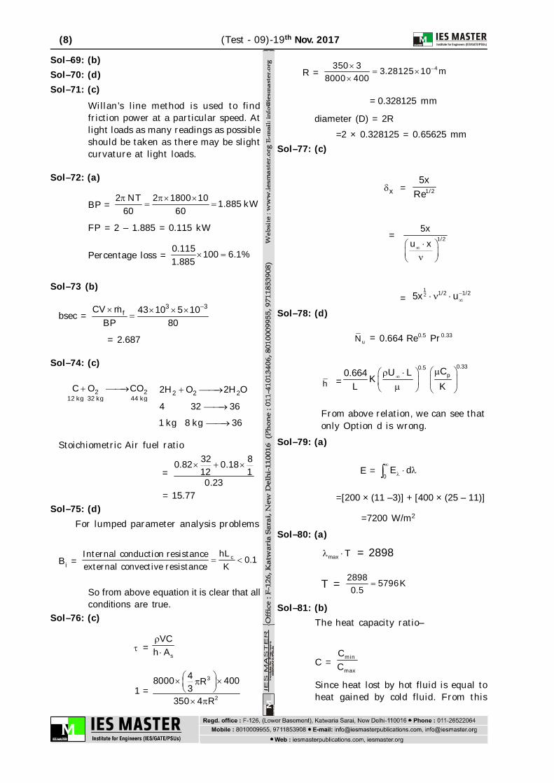
Sol–76: (c)
=s
VCh A
1 =3
2
48000 400R3
350 4 R
R = 4350 3 3.28125 10 m8000 400
= 0.328125 mm
diameter (D) = 2R
=2 × 0.328125 = 0.65625 mmSol–77: (c)
x = 1/25x
Re
= 1/25x
u x
=12 1/2 1/25x u
Sol–78: (d)
uN = 0.5 0.330.664 Re Pr
h =0.330.5
pCU L0.664 KL K
From above relation, we can see thatonly Option d is wrong.
Sol–79: (a)
E =0
E d
=[200 × (11 –3)] + [400 × (25 – 11)]
=7200 W/m2
Sol–80: (a)
max T = 2898
T = 2898 5796K0.5
Sol–81: (b)The heat capacity ratio–
C = min
max
CC
Since heat lost by hot fluid is equal toheat gained by cold fluid. From this
(9) (Test - 09)-19th Nov 2017
concept it is concluded that a fluidhaving small specific heat has maximumtemperature change so
hT = 160 – 85 = 75°C
cT = 135 – 35 = 100°C Heat transferred from hot fluid to cold
fluid,
h hC T = c cC T
h
c
CC =
c
h
TT
cT > hT
Ch > Cc
Cc is minimum and Ch maximum, soHeat capacity ratio
C = c h
h c
C T 75 = 0.75= =C T 100
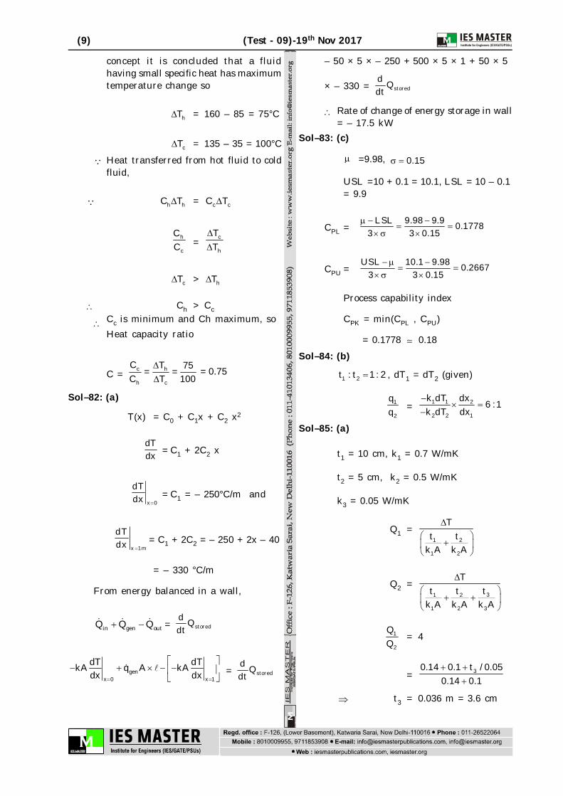
Sol–82: (a)
T(x) = C0 + C1x + C2 x2
dTdx = C1 + 2C2 x
x 0
dTdx
= C1 = – 250°C/m and
x 1m
dTdx
= C1 + 2C2 = – 250 + 2x – 40
= – 330 °C/m
From energy balanced in a wall,
in gen outQ Q Q = storedd Qdt
genx 0 x 1
dT dTkA q A kAdx dx
= stored
d Qdt
– 50 × 5 × – 250 + 500 × 5 × 1 + 50 × 5
× – 330 = storedd Qdt
Rate of change of energy storage in wall= – 17.5 kW
Sol–83: (c)
=9.98, 0.15
USL =10 + 0.1 = 10.1, LSL = 10 – 0.1= 9.9
CPL =LSL 9.98 9.9 0.1778
3 3 0.15
CPU =USL 10.1 9.98 0.2667
3 3 0.15
Process capability index
CPK = min(CPL , CPU)
= 0.1778 0.18Sol–84: (b)
1 2t : t 1 : 2 , dT1 = dT2 (given)
1
2
qq = 1 1 2
2 2 1
k dT dx 6 :1k dT dx
Sol–85: (a)
t1 = 10 cm, k1 = 0.7 W/mK
t2 = 5 cm, k2 = 0.5 W/mK
k3 = 0.05 W/mK
Q1 =1 2
1 2
Tt t
k A k A
Q2 =31 2
1 2 3
Ttt t
k A k A k A
1
2
= 4
= 30.14 0.1 t / 0.050.14 0.1
t3 = 0.036 m = 3.6 cm

(10) (Test - 09)-19th Nov. 2017
Sol–86: (a)
Heat conducted= Heat convected
dTkAdx
= shA(T T )
dTdx = s
h T Tk
= –63157°C/cmSol–87: (a)
Eb = 4T
= 8 45.67 10 (800)
= 23.2 kW/m²
A = 2 2D 0.2
= 20.1257m
time = 5 × 60 = 300 sec.
Q = 23.2 × 0.1257 × 300= 874.87 kJ
Sol–88: (a)
r cQ d Q d qd = VcdT
dTd = r cQ Q q
Vc
Vc = r cQ Q qdT / d
=4000 5000 2000
0.5
= 2000 J/°CSol–89: (c)
Total radiation absorbed = 500 – 150 –225
= 125 W/m²
= 125 0.25500
Sol–90: (b)
11 12 13F F F = 1
by symmetry F12 = F13 = 0.5
by reciprocity
F21 = 112
2
A 2LF 0.5A L
= 0.71
Sol–91: (b)Thermal resistance without shield
=1 0.8 1 0.81
0.8 0.8
= 1.5Thermal resistance with shield shouldbe
= 10 × 1.5 = 15
15 = s
s
11 0.8 1 0.81 10.8 0.8
s = 0.142Sol–92: (a)
Radiation occur in gases too.Sol–93: (d)
Direct view factor = N(N 1)2
(6 1)6 152
Sol–94: (a)Thermal conductivity of electricalconductors in generally high due topresence of free electrons. Thermalconductivity of gases increase withtemperature k T whereasconductivity of liquid is function oftemperature density and otherthermophysical properties.
Sol–95: (b)The strong heat conducting property ofdiamond is due to the covalent bondingbetween its atoms.
Sol–96: (a)
q = dTkAdx
dT1 = dT2
q1 = q2
1dT0.5W/mK×A×
1 m = 22
dTk A0.5

(11) (Test - 09)-19th Nov 2017
k2 = 0.5 × 0.5
= 0.25 W/mKSol–97. (b)
Only 1 dimension heat conduction existsand no heat generation is considered.
Sol–98. (c)Equivalent emissivity for radiationexchange between completely enclosedbody small compared to enclosing body(subscript 1 for enclosed body) = 1
1 = 0.5Sol–99: (b)
factor =
3 31 2
1 1 3 3 3 3 2 2
11 11 11 1
F F
F1–3 = F3–2 = 1
Factor =
31 2
1 3 2
111 12 2
= 1 2 3
2 3 1 2 1 3 1 2 32 2
Sol–100: (d)
Area of air heater
A = 60 m2
Overall heat transfer coefficient
U = 100 W/m2K
Heat capacity rate of both hot and coldfluid,
Ch = Cc = 2000 W/K
Number of Transfer Units i.e. NTU
NTU = min
UAC
= 100 60
2000
= 3
Sol–101: (c)Objectives of method study are: establishing standard procedures
development of better layout byestablishing method involvingsmooth and continuous flow ofmaterial
devising safe work method andthus maintaining safe workingconditions
effective utilisation of men,material, machinery
efficient material handling efficient planning
Sol–102: (a)During different development stagesof a layout the following methods maybe used.1. Process Flow Charts: They
show, how different componentparts assemble, in sequence ofoperations to form sub-assemblieswhich in turn lead to assemblies(finished products).
2. Material Movement Patterns:The flow pattern of materials-in-process is traced and layout isbuilt around it.
3. Layout Analogues: They covertwo-dimensional cutouts ortemplates and three-dimensionalmodels.
Templates: They are used to developplant layout. Templates or cutoutsshow the plan of the various facilitiesand the building. They show theactual floor space utilization. Thetemplates can be placed and attachedand the building. They show theactual f loor space util ization.Templates save a lot of time andlabour which otherwise would bespent in making drawings for eachalternative plant layout arrangement.They visually present variouscharacteristics, advantages andlimitations of a layout. A two-dimensional template gives machineoutline and its details whereas a blocktemplate shows the boundary of themaximum projected area of themachine. Templates, though simpleand inexpensive, do not give realsituation effect which is obtainedthrough the use of three-dimensionalmodels or block models.

(12) (Test - 09)-19th Nov. 2017
Two dimensionaltemplate
Blocktemplate
Travel Chart: A travel chart as thename suggests is a chart or record ofthe amount of travel by the materialin-process while going from machineto machine or from one departmentto another. The amount of traveldepends upon the frequency ofmovements between sections ordepartments. A travel chart helpsimproving the existing plant layout.
Gantt Chart: It is used in projectmanagement. It shows activitiesdisplayed against time. It is used totrack project schedules.
Sol–103:(d)It speficifies1. The sizing and timing of
production orders for specificitems.
2. The sequencing of individuals jobsand
3. the short term allocation ofresoucesto individual activitiesand operation.
Sol–104:(d)Product layout is generally used insystems where a product has to bemanufactured or assembled in largequantities. Further, the machineryand auxilliary services are locatedaccording to the processing sequenceof the product. Thus, if the productdesign or process change occurs, thelayout may become obsolete thus,there is less flexibility and hence thevariety of products is low. It involvesless in-process inspection, incomparison to process layout.
Sol–105:(a)Product layout: Where a largequantity of products is to be produced.Process layout: Where a large varietyof products is manufactured.
Combined layout:Where item is beingmade in different types of sizes.Fixed position: Where too heavy orhuge layout item is used as rawmeterial.
Sol–106:(c)Dispatching function in productionplanning and control refers toauthorising a production work orderto be launched.
Sol–107: (d)Capital for purchase of raw materials,payment of wages to workers,transport cost etc. are called workingcapital. The floating or workingcapital is required to meet the currentexpenses on raw materials and stores,incidental to marketing products, andalso to meet the outstanding dues inrespect of goods supplied and lastlyfor paying wages and other expensesfor day-to-day requirements.Thus, working capital is themanagement of inventories andpayment of wages etc.
Sol–108: (d)
2
14
3T
S
h4 = 65 kJ/kg, h1 = 165 kJ/kg
h2 = 185 kJ/kg
Refrigeration capacity ‘Rc’ = 5 kW
Energy performance ratio (Co-efficient ofperformance)
‘EPR’ = Desired effect
work input
= 1 4
2 1
h h 165 65 5h h 185 165
(13) (Test - 09)-19th Nov 2017
Power consumed by compressoris given by
P = LQ 5 1 kWCOP 5
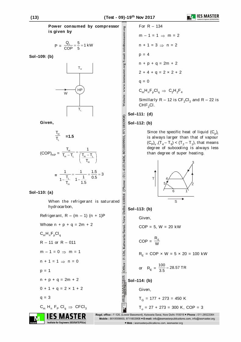
Sol–109: (b)
HP
TH
TL
W
Given,
H
L
TT =1.5
(COP)HP = H
H LH L
H
T 1T TT T
T
= L
H
1 1 1.5 3T 1 0.511 1.5T
Sol–110: (a)
When the refrigerant is saturatedhydrocarbon,
Refrigerant, R – (m – 1) (n + 1)P
Whose n + p + q = 2m + 2
CmHnFpClq
R – 11 or R – 011
m – 1 = 0 m = 1
n + 1 = 1 n = 0
p = 1
n + p + q = 2m + 2
0 + 1 + q = 2 × 1 + 2
q = 3
Cm Hn FP Clq CFCl3
For R – 134
m – 1 = 1 m = 2
n + 1 = 3 n = 2
p = 4
n + p + q = 2m + 2
2 + 4 + q = 2 × 2 + 2
q = 0
CmHnFpClq C2H2F4
Simillarly R – 12 is CF2Cl2 and R – 22 isCHF2Cl.
Sol–111: (d)
Sol–112: (b)
Since the specific heat of liquid (Cp)lis always larger than that of vapour(CP)v ,(T4 – T5) < (T2 – T1), that meansdegree of subcooling is always lessthan degree of super heating.
3
16
4T
S
25
Sol–113: (b)
Given,
COP = 5, W = 20 kW
COP = ERW
RE = COP × W = 5 × 20 = 100 kW
or RE = 100 28.57 TR3.5
Sol–114: (b)
Given,
TG = 177 + 273 = 450 K
To = 27 + 273 = 300 K, COP = 3

(14) (Test - 09)-19th Nov. 2017
COP of vapour absorption system is givenby
COP = G OE
G O E
T TTT T T
3 = E E E
E E E
T T 150 T450 300450 300 T 450(300 T ) 3(300 T )
9 × 300 – 9TE = TE
TE = 9 300 270 K
10
or 270 – 273 = –3°C
Sol–115. (c)
Given, Pvs = 4.25 kPa, P = 1 bar = 100 kPa
mv = 2.5 kg
As air is saturated, relative humidity is100% i.e. Pv = Pvs = 4.25 kPa
Specific humidity
' ' = v
v
0.622 P 0.622 4.25P P 100 4.25
= 0.0276 kg/kg of dry air
But, = v
a
m 0.0276m
mass of dry air,
‘ma’= vm 2.5 90.58 kg0.0276 0.0276
Sol–116: (d)
Given, RSHF = 0.75, RLH = 40 KW
RSHF = RSH
RLH RSH
0.75 = RSH
RSH 40
or, RSH = 40 0.75 120 kW
0.25
Sol–117. (b)
Sol–118: (b)
Sensible heat load = 0.0204 × cmm ×T
= 10 15 50.0204 2 (45 25)
60
= 10.2 kW
Sol–119: (b)
t = 40°C3
t = 25°C2 t = 15°C1
By pass factor = 3 2
3 1
t t 40 25 0.6t t 40 15
Coil efficiency = 1 – BPF = 1 – 0.6 = 0.4
Sol–120: (b)
RSHF = RSHRTH
RSH = RSHF × RTH = 0.6 × 120 = 72 kW
RLH = RTH – RSH = 120 – 72 = 48 kW
RLH = 50 × cmm × 1 2( )
48 = 50 × 90 × (0.012 – 2 )
2 = 480.012 0.00133 kg / kg of dry air
50 90
Sol–121: (b)
Binding constraint means theconstraint should form boundary onthe feasible region in the direction ofoptimal movement of objectivefunction, (i.e. away from origin in caseof maximisation problem and towardsorigin in case of minimisationproblem)
Sol–122: (b)Sol–123: (a)Sol–124: (d)
Gantt charts are used to solvesequencing problems graphically.
(15) (Test - 09)-19th Nov 2017
Sol–125: (b)Sol–126: (c)
On an average as much as 15% to 22%money saving are achieved byselecting a proper preventivemaintenance program. But preventivemaintenance will not completelyeliminate catastrophic failures(sudden breakdown) but will reduceits frequency of occurance.
Sol–127: (b)The best parameter to compare dieselengine of different size is specificbrake fuel consumption i.e. fuel con-sumption per unit brake power. Thevolumetric efficiency depends upondesign of components also not only onsize parameters. Air fuel ratio is notparameter to compares same categoryof engines. Swept volume of enginehas no meaning in comparison of per-formance of different engine.
Sol–128: (b)Sol–129: (b)
Exact estimation of cooling load in airconditioning plant gives optimum designwhich runs at minimum total cost andgives maximum comfort condition.The external load is due to outside heatsource or gain e.g. heat leakage throughwall, ventilation air load etc. Theinternal load is due to internal heatsource or gain e.g. occupant, applienceslights etc.
Sol–130: (a)Sprues of converging passage is used toavoid aspiration effect. Due toentrapement of air in casting createsblow holes.
Sol–131: (c)Sol–132: (b)Sol–133: (d)
USM must uses soft tool due to highvibration.
Sol–134: (c)Sol–135: (b)
Single start threads are used forfastening purposes due to easilytightning and losening with smallamount of force.
Sol–136: (c)Abrasives used in grinding are harderthan milling cutters.
Sol–137: (b)
Sol–138: (b)
Sol–139: (b)Sol–140: (d)
• Method of governing used in dieselengine is quality governing
Sol–141: (b)
Sol–142: (d) does not play any role in steady stateheat conduction.
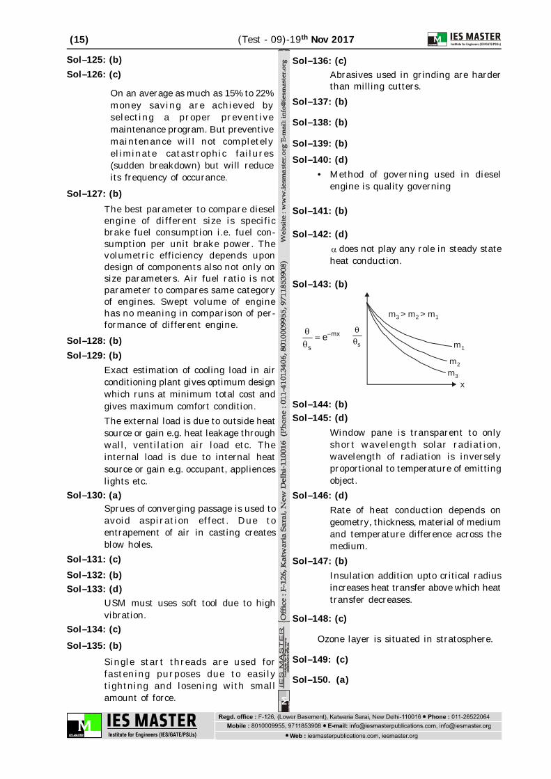
Sol–143: (b)
mx
se m1
m2m3
m m m3 2 1> >
x
s
Sol–144: (b)Sol–145: (d)
Window pane is transparent to onlyshort wavelength solar radiation,wavelength of radiation is inverselyproportional to temperature of emittingobject.
Sol–146: (d)Rate of heat conduction depends ongeometry, thickness, material of mediumand temperature difference across themedium.
Sol–147: (b)Insulation addition upto critical radiusincreases heat transfer above which heattransfer decreases.
Sol–148: (c)
Ozone layer is situated in stratosphere.
Sol–149: (c)
Sol–150. (a)