ANSWERS - IES Master - Coaching for ESE, GATE and PSUs...
21
Office : F-126, Katwaria Sarai, New Delhi-110016 (Phone : 011-41013406, 7838813406, 9711853908) Website : www.iesmaster.org E-mail: [email protected] ESE-2017 PRELIMS TEST SERIES Date: 1st January, 2017 28. (b) 29. (d) 30. (a) 31. (a) 32. (d) 33. (a) 34. (a) 35. (c) 36. (b) 37. (b) 38. (d) 39. (a) 40. (a) 41. (b) 42. (a) 43. (c) 44. (c) 45. (a) 46. (b) 47. (b) 48. (b) 49. (a) 50. (c) 51. (b) 52. (d) 53. (d) 54. (b) 55. (c) 56. (b) 57. (d) 58. (d) 59. (b) 60. (d) 61. (a) 62. (b) 63. (a) 64. (c) 65. (d) 66. (b) 67. (d) 68. (c) 69. (a) 70. (d) 71. (d) 72. (d) 73. (a) 74. (c) 75. (d) 76. (c) 77. (a) 78. (d) 79. (a) 80. (d) 81. (a) 82. (c) 83. (c) 84. (b) 85. (b) 86. (d) 87. (d) 88. (d) 89. (c) 90. (c) 91. (c) 92. (b) 93. (a) 94. (d) 95. (a) 96. (d) 97. (a) 98. (d) 99. (d) 100. (b) 101. (a) 102. (d) 103. (c) 104. (d) 105. (b) 106. (c) 107. (d) 108. (c) 109. (b) 110. (c) 111. (c) 112. (d) 113. (c) 114. (b) 115. (b) 116. (b) 117. (d) 118. (d) 119. (d) 120. (c) 121. (d) 122. (c) 123. (d) 124. (d) 125. (b) 126. (b) 127. (d) 128. (b) 129. (a) 130. (d) 131. (d) 132. (b) 133. (b) 134. (d) 135. (a) 136. (c) 137. (a) 138. (a) 139. (a) 140. (d) 141. (b) 142. (d) 143. (d) 144. (d) 145. (d) 146. (a) 147. (b) 148. (a) 149. (c) 150. (d) 151. (d) 152. (a) 153. (b) 154. (b) 155. (a) 156. (a) 157. (c) 158. (c) 159. (a) 160. (b) ANSWERS 1. (b) 2. (a) 3. (c) 4. (a) 5. (a) 6. (a) 7. (b) 8. (d) 9. (c) 10. (d) 11. (b) 12. (b) 13. (b) 14. (a) 15. (d) 16. (a) 17. (d) 18. (a) 19. (a) 20. (b) 21. (b) 22. (d) 23. (b) 24. (c) 25. (b) 26. (c) 27. (b)
Transcript of ANSWERS - IES Master - Coaching for ESE, GATE and PSUs...

Office : F-126, Katwaria Sarai, New Delhi-110016 (Phone : 011-41013406, 7838813406, 9711853908)
Website : www.iesmaster.org E-mail: [email protected]
ESE-2017 PRELIMS TEST SERIESDate: 1st January, 2017
28. (b)
29. (d)
30. (a)
31. (a)
32. (d)
33. (a)
34. (a)
35. (c)
36. (b)
37. (b)
38. (d)
39. (a)
40. (a)
41. (b)
42. (a)
43. (c)
44. (c)
45. (a)
46. (b)
47. (b)
48. (b)
49. (a)
50. (c)
51. (b)
52. (d)
53. (d)
54. (b)
55. (c)
56. (b)
57. (d)
58. (d)
59. (b)
60. (d)
61. (a)
62. (b)
63. (a)
64. (c)
65. (d)
66. (b)
67. (d)
68. (c)
69. (a)
70. (d)
71. (d)
72. (d)
73. (a)
74. (c)
75. (d)
76. (c)
77. (a)
78. (d)
79. (a)
80. (d)
81. (a)
82. (c)
83. (c)
84. (b)
85. (b)
86. (d)
87. (d)
88. (d)
89. (c)
90. (c)
91. (c)
92. (b)
93. (a)
94. (d)
95. (a)
96. (d)
97. (a)
98. (d)
99. (d)
100. (b)
101. (a)
102. (d)
103. (c)
104. (d)
105. (b)
106. (c)
107. (d)
108. (c)
109. (b)
110. (c)
111. (c)
112. (d)
113. (c)
114. (b)
115. (b)
116. (b)
117. (d)
118. (d)
119. (d)
120. (c)
121. (d)
122. (c)
123. (d)
124. (d)
125. (b)
126. (b)
127. (d)
128. (b)
129. (a)
130. (d)
131. (d)
132. (b)
133. (b)
134. (d)
135. (a)
136. (c)
137. (a)
138. (a)
139. (a)
140. (d)
141. (b)
142. (d)
143. (d)
144. (d)
145. (d)
146. (a)
147. (b)
148. (a)
149. (c)
150. (d)
151. (d)
152. (a)
153. (b)
154. (b)
155. (a)
156. (a)
157. (c)
158. (c)
159. (a)
160. (b)
ANSWERS
1. (b)
2. (a)
3. (c)
4. (a)
5. (a)
6. (a)
7. (b)
8. (d)
9. (c)
10. (d)
11. (b)
12. (b)
13. (b)
14. (a)
15. (d)
16. (a)
17. (d)
18. (a)
19. (a)
20. (b)
21. (b)
22. (d)
23. (b)
24. (c)
25. (b)
26. (c)
27. (b)

IES M
ASTER
(2) ME (Test-20), Objective Solutions, 1st January 2017
Sol–1: (b)For option, (a)
1 4 400Area of ABC 2Area of BC51 4 700
= 2 0.2867
For option (b),Area of ABCArea of ABC51
1 4 4002
1 4 400 300 42
= 0.4
For option (c),1 4 400Area of ABC 2 0.286
Area of ABC51 700 4
For option (d),1 4 400Area of ABC 21Area of ABC51 4 12002
= 0.33Sol–2: (a)
Work done = area of pressure-volumediagram
= 1
0.03 0.01 4 22
= 51 0.02 6 10 6kJ2
mp V = 6 kJ
pm =
60000.03 0.01 =
6000 3 bar0.02
Sol–3: (c)1–2 and 1'–2'– constant temperatureprocess,3–1 and 3'–1'– constant entropy process,2–3 – constant volume process,2'–3' – constant pressure process
Sol–4: (a)
U = 30 KJ
If Q = – 50 KJ
and W = – 80 KJ
Then, Q W U 50 80 30kJ= =
Sol–5: (a)Path function – their magnitudes dependon the path followed during a process.Example work, heat.Point function- they depend on the stateonly and not on how a system reachesthat state. All properties are pointfunctions.Extensive properties depend on the massof the substance, while intensiveproperties are independent of mass.
Sol–6: (a)
Since, the tank is rigid, so the cooling ofthe gas will be a constant volume process.
Sol–7: (b)
In a cyclic process, the net change ininternal energy is zero.
Sol–8: (d)For isothermal process
U = mCVdT = 0 Q = U W
Q = WSol–9: (c)
The amount of entropy generated
Sgen =
1 2
1 2
T TQ
T T
= 1600 ×
800 400800 400 = 2 kJ/k
Sol–10: (d)
Efficiency = net work doneheat input
= area enclosed in T S diagramheat input
=
1 5 1 800 4002 0.25=
800 5 1
IES M
ASTER
(3) ME (Test-20), Objective Solutions, 1st January 2017
Sol–11: (b)Efficiency of carnot engine workingbetween 627°C and 27°C will be
carnot = 300 21 0.66= =900 3
Efficiency of the heat engine
HE = 50 kW
3 kg / s 75000 KJ / Kg3600
= 50 36003 75000
= 0.8
Since HE > carnot , so this engine is notpossible.
Sol–12: (b)Area under T-s diagram represents heattransfer during the reversible process.Since temperature and entropy bothincrease during the process, hence, heattransfer is positive and heat is added orabsorbed.
Sol–13: (b)Displacement thickness
* = 0
u1 dyu
= 0
y1 dy
= 2
0
yy2
=2
2
= 2
=2
Sol–14: (a)
u = 2 21 p R r4 x
umax = 21 p R4 x
max
uu =
2r1R
Sol–15: (d)For continuity equation to be satisfied,
u vx y
= 0
ux
= 6x xy = 6 yx
vy = 6 y
v = 2y6y
2
Sol–16: (a)Rotation is defined as the movement of afluid element in such a way that both ofits axes (horizontal as well as vertical)rotate in the same direction.
It is equal to
1 v u2 x y
for a two-dimensional element in x-y plane. Therotational components are
z =
1 v u2 x y
x =
1 w v2 y z
y =
1 u w2 z x
Sol–17: (d)
Q h
Q = c h
dQ = c dh2 h
dQQ =
cdh dh=2h2 h c h
Since dhh
= 2%
dQQ = 1%
Sol–18: (a)For laminar boundary layer on a smooth
plate, x
5x Re
.
x
For turbulent boundary layer on a smooth
plate, x = 1/5
x
0.376Re
.
x4/5

IES M
ASTER
(4) ME (Test-20), Objective Solutions, 1st January 2017
Sol–19: (a)According to Newton’s law of viscosity,
= 2du 300.001 3N/m= =dy 0.01
Force applied = stress × area= 3 × 0.1 = 0.3 N
Sol–20: (b)
AV = constant
ln A ln V ln ln= (constant)
dA dV dA V
= 0
Sol–21: (b)Reynold’s Number (Re): It is definedas the ratio of inertia force of a flowingfluid and the viscous force of the fluid.Froude’s Number (Fe): The Froude’snumber is defined as the square root ofthe ratio of inertia force of a flowing fluidto the gravity force.Euler’s Number (Eu): It is defined asthe square root of the ratio of the inertiaforce of a flowing fluid to the pressureforce.Weber’s Number (We)- It is defined asthe square root of the ratio of the inertiaforce of a flowing fluid to the surfacetension force.Mach’s Number (M): Mach’s numberis defined as the square root of the ratioof the inertia force of a flowing fluid tothe elastic force.
Sol–22: (d)For the solid P, weight = buoyancy force
p pV g = pw
Vg
2
P = w
2
For the solid Q, Q QV g = QW
2Vg
3
Q = w23
p
Q
= w ww 3/ =z 3 4
Sol–23: (b)
D25
50
A
B
D
100
Let pressure at point D be pd and at point dD be p
Then,pD + 0.65 × 25 + 0.8 × 50 = pA
dp + 100 × 1.0 = pB
But pD = dp
hence, pB – pA = 100 × 1.0 – (0.65 × 25+ 0.8 × 50) = 43.75
Sol–24: (c)Let volume of metallic piece be Vm
and density of water be w
Density of metallic piece be m
Then,
m mV g = 80 ...(i)
m mV g – W mV g = 60 ...(ii)
80 – w mV g = 60
w mV g = 20
m
w
= 4
Sol–25: (b)The stability of a floating body isdetermined from the position of Meta-centre (M).In case of floating body, theweight of the body is equal to the weightof liquid displaced.

IES M
ASTER
(5) ME (Test-20), Objective Solutions, 1st January 2017
Stable Equilibrium. If the point M isabove G, the floating body will be instable equilibrium. If a slight angulardisplacement is given to the floating bodyin the clockwise direction, the centre ofbuoyancy shifts from B to B1 such thatthe vertical line through B1 cuts at M.Then the buoyant force FB through B1and weight W through G constitute acouple acting in the anti-clockwisedirection and thus bringing the floatingbody in the original position.
W M
G
BFB
B1
DisturbingCouple
Unstable Equilibrium. If the Point Mis below G, the floating body will be inunstable equilibrium as shown in figure.The disturbing couple is acting in theclockwise direction. The couple due tobuoyant force FB and W is also acting inthe clockwise direction and thusoverturning the floating body.
W
GM
BB1
FBNeutral Equilibrium: If the point M isat the centre of gravity of the body, thefloating body will be in neutralequilibrium.
Sol–26: (c)An adverse pressure gradient occurs whenthe static pressure increases in thedirection of flow. Mathematically, this is
expressed as dP 0dx for a flow in the
positive x direction.When area of the flow increases and hencevelocity of flow along the direction of fluiddecreases. Due to decrease of velocity, thepressure increases in the direction of flow,and hence pressure gradient dP/dx > 0.The velocity of the layer adjacent to thesolid surface along the length of the solidsurface goes on decreasing as the kineticenergy of the solid surface goes ondecreasing as the kinetic energy of thelayer is used to overcome the frictionalresistance of the surface. Thus, thecombined effect of positive pressuregradient and surface resistance reduce themomentum of the fluid. A stage comeswhen the momentum of the fluid is unableto overcome the surface resistance andthe boundary layer starts seperating fromthe surface.
Sol–27: (b)The cyclone separators are the devicesto remove the dust particle from gasby utilizing centrifugal force createdby spinning gas streams.The collection efficiency of a separator
= Mass of dust particles removedMass of dust entered with gas
This efficiency increases with increasein –(i) Particle size and density.(ii) Inlet gas velocity(iii)Number of gas revolution(iv)Smoothness in cyclone walls.
Sol–28: (b)As per temperature and economy re-quirement the path of flue gases,Combustion chamber SuperheaterReheat economiser Air preheaterElectrostate -precipitator stack.ID fan is put after electrostatic precipi-tator to reduce power consumption andblade erosion due to dust i.e. more isdust in the gases, more is power re-quirement due to high mass of dustladden flue gases and blade erosion ishigh.

IES M
ASTER
(6) ME (Test-20), Objective Solutions, 1st January 2017
Sol–29: (d)1. Velocity compounded i.e. Curtis
turbine gives less rotational speed(but steam flow velocity is very high)and reduced efficiency due to highsteam flow losses.
2 The power consumption of compressoris proportional to absolute velocity ofair at blade tip which of higher forhigh velocity impeller of big diameter.
3. The relative velocity of fluid flow incompressor rotor reduces andincreases in reaction turbine.So statement 1, 2 and 4 are correct.
Sol–30: (a)The one stage regenerative Rankinecycle is shown in figure.
T1
2875 6
43
sSpecific output of a turbine is reducedbecause some power is compromised inregeneration. The steam quality at exitis improved by reheating notregeneration. The regeneration improvescycle efficiency because heat addition atlow temperature (i.e. in 5–6 process) isreduced. The condenser load i.e. heatrejection in condenser is reduced becausesome rejected heat is supplied to steamat high pressure.
Sol–31: (a)The variation of volumetric efficiencywith pressure ratio and clearance ratiois shown in figure.
c1
c2
c3
c1 < c < c2 31.0
r (P /P )P 2 1
At constant clearance ‘c ’ anddecrease in pressure ratio, thevolumetric efficiency increases.
At constant pressure ratio asclearance ‘c’ reduces, the volumetricefficiency increase.
Increase in delivery pressure meansincrease in pressure ratio i.e.decrease in volumetric efficiency.Ambient temperature does not affectvolumetric efficiency.
Sol–32: (d)For 50% reaction in axial compressormeans half of total pressure rise is inrotor. In this situation, the inlet guidevane angle 1' ' is equal to blade exit
angle 2
1 = 2
At the same time
1 = 2
These two conditions gives symmetricalvelocity triangles at inlet and exit.
1 1
u
22
V1V0
Vw1
Vw2Va
V2
u
Inlet
Exit
Symmetrical triangles i.e. symmetricalblades.

IES M
ASTER
(7) ME (Test-20), Objective Solutions, 1st January 2017
Sol–33: (a)
Because of large power consuming com-pressor in the gas turbine, net outputis less. So for comparable net power out-put the steam turbine is small, becauseof this high power consuming compres-sor. Another reason for big size of gasturbine is low pressure ratio used ingas turbine. In gas turbine, pressureratio is about 6-8 but in steam turbineis 150-250.
Sol–34: (a)Maximum pressure ratio is possible onlyin maximum efficiency (Carnot effi-ciency) case.Maximum pressure ratio
rP =1max
min
TT
In this situation, the work output iszero i.e. work consumed by compressoris equal to work produced by turbinei.e. work ratio is minimum (Theoreti-cally zero).
Sol–35: (c)
TT
T1 = Tmin1
2
wc
T3 = Tmax
wtT4
sT-s diagram of Brayton cycle -For maximum net work done
Wnet = Wt – Wc
The pressure ratio including isentropicefficiencies of compression and expan-sion.
rp = 2 1maxt c
min
TT
Assuming
t = c 1=
rp = 2 21 1max 3
min 1
T T=T T
Sol–36: (b)
Lc =
2A 4L 5P 2 4
= 7cm Increase in length = Lc – L = 7cm – 5cm
= 2cmSol–37: (b)
[ fin]adiabatic tip 2
tan h (mL) hA2KP
tan h(mL) 2h r2
k 2 r
tan h(mL) 2hrK
Sol–38: (d)Sol–39: (a)
QQ = a RTQ QQ
Q Q Q
1 =
=
R
R T
Q / QQ Q1Q Q
= R
R T
QQ Q Q
=
150 15050000 625150 225
50
= 6 0.2425
Sol–40: (a)
T = 1 2 1 21 2 3f f f 1 f

IES M
ASTER
(8) ME (Test-20), Objective Solutions, 1st January 2017
= (0.3 × 0.14) + 0.8(0.7 – 0.14) + 0.1 × (1 – 0.7)
= 0.52Sol–41: (b)
Directly =
N N 1 10 9 45
2 2Total required for analysis = N2 = 100Required ratio = 45/100 – 45 = 0.82
Sol–42: (a)At equilibriumEnergy absorbed = energy emitted
0.4 × 1400 = 0.6 × 5.67 × 10–8 × T4
Sol–43: (c)
h (Tf – Tth) = 4 4th wT T
Tf =
4 4th w
thTT T
h
4 4th wT Th
is called radiation
correction.Sol–44: (c)
F12 + F11 + F13 = 10.035 + 0 + F13 = 1
F13 = 1 – 0.035= 0.965
A1F12 = A2F21A1 = A2 F21 = F12 = 0.035
F21 + F22 + F23 = 10.035 + 0 + F23 = 1
F23 = 0.965A2F23 = A3F32
F32 = 2 0.965 0.08
24F13 – F32 = 0.965 – 0.08 = 0.885
Sol–45: (a)
NTU =min
UAC
2.5 =
min
100 12C
Cmin = 480 W
capacity ratio = 480 0.48
1000
Sol–46: (b)
NTU =min
UAC
UA = Cmin × NTU= 800 × 0.37= 296 kW/K
Sol–47: (b)The vapour compression refrigerationcycle on P-h chart,
P
h15
4 32
The enthalpy at various points,h1 = inlet to compressor
= 1500 kJ/kgh2 = outlet to compressor
= 1800 kJ/kg
h4 = 5h inlet to evaporator orexit of condenser
= 300 kJ/kg Coefficient of performance
CoP = 1 5
2 1
h hRw h h
= 1500 300 1200 41800 1500 300

IES M
ASTER
(9) ME (Test-20), Objective Solutions, 1st January 2017
Sol–48: (b)
S
T
14
3
2QR
QA
Standar vapour compression refrigerationcycle consists of four process:(1 – 2) Isentropic compression (2 – 3) Constant Pressure heatrejection(3 – 4) Throttling (Isenthalpic)Expansion(4 – 1) Constant Pressure heataddition.
Sol–49: (a)Points regarding vapour absorption (VAS)refrigeration system. VA systems operates on low grade
energy (heat) whereas vapourcompression (VCS) refrigerationsystems operates on high grade energy.
In VA systems compressor is replacedwith generator, absorber and a pump.
Pump is required to circulates solution(Liquid) in various components sorequire very small or negligible work.
VA systems are used where largewaste heat is available
Solar refrigeration systems are basedon VA cycle.
Sol–50: (c)Desirable properties of refrigerant:(i) Low specific heat of liquid and high
specific heats of vapour(ii) Low specific volume(iii) High thermal conductivity(iv) Low freezing point(v) Low boiling point
(vi) High latent heat of vapourization(vii)Non-toxic(viii) Ozone friendly(ix) High critical pressure and
temperature(x) Low cost.
Sol–51: (b)Statements 1 and 3 correct, while 2 iswrong because in dehumidification processthe dew point temperature decrease
Sol–52: (d)
0.015
DBT
0.0070.01
2
1
15ºC 25ºC 45ºC
RSH
GSHFLRLH
SaturationCurve
RSHF
O
Room sensible heat,RSH = 0.0204 × 1000 × (25 – 15)
= 204 kWRoom Latent heat,
RLH = 50 × supply air flow rate ×
= 50 × 1000 × (0.01 – 0.007)= 150 kW
Sol–53: (d) Given,
L
H
TT = 0.8
Q1
W
Q2
TH
R/HP
TL
The COP of heat pump,

IES M
ASTER
(10) ME (Test-20), Objective Solutions, 1st January 2017
(COP)HP = H
LH L
H
T 1 1TT T 1 0.81T
= 5Sol–54: (b)
The Bell Colemen Cycle on P-V diagram.P
3 2
4 1V
Process:(1 2): Isentropic compression(2 3): Constant pressure heat rejection(3 4): Isentropic expansion(4 1): Constant pressure heat rejection
Sol–55: (c)During design of knock free combustionchamber, following points should be keptin mind. Flame travel distance should be small. Exhaust valve and spark plug should
be kept near as possible. Wedge shape satisfy reduced knock
condition.So wedge shape chamber and short flametravel satisfy the criterion for reducedengine knock.
Sol–56: (b)Higher compression ratio in CI enginereduces diesel knock because it startsearly auto ignition. Higher coolant tem-perature also reduces it. But higherspeed and injection advance both in-creases diesel knock because of delayedauto ignition and large amount of fuelavailable for uncontrolled combustionstage.
Sol–57: (d)The Stoichiometric equation of carbon,
2 212 32 44C O CO
CO2 produced by one kg carbon –
= 4412
= 11 kg3 CO2/kg carbon
Sol–58: (d)Three way catalytic converter controlsHC, CO and NOx emission as shownbelow
SecondaryAir
HC/COElement(Pt/Pd)NOx element
(Rhodium)
PM emission cannot be controlled bythis because they are big compoundscontaining carbon which are not burntduring regular combustion in CI engine.
Sol–59: (b)Deficit air combustion means combus-tion is not complete and some gas willburn to carbon monoxide and some tocarbon dioxide. And along with this, thepercentage of oxygen is also become zeroi.e. whole oxygen is utilized.
Sol–60:(d)
Otto = 111
r
i.e. Otto = f(r, )Here r is not property of working substance.Lower cut-off ratio leads to better efficiency.

IES M
ASTER
(11) ME (Test-20), Objective Solutions, 1st January 2017
Sol–61: (a)All above factors except (a) does not effectoptical properties of solar radiation fallingon flat plate collector.
Sol–62. (b)Hour angle is positive before noon.
Sol–63. (a)
95° hour angle corresponds to 95 6015
minutes = 380 minutes = 6 hr 20 minSince hour angle is positive, so itcorresponds to 1200 – 0620 hr
= 0540 hrSol–64. (c)
rb =z
cos cos30cos cos60
rb =
32 3 1.73212
Sol–65. (d)w1 = 1 m t = 0.015 m
d = 1
1
4 w t2 w t
d = 4 1 0.0152 1 0.015
d 0.0295 m
Sol–66. (b)
7000
0
20
40
60
80
100
100 200 300 400 500 600Operating temperature (°C)
Effic
ienc
y (%
)Sol–67. (d)
Metallic contact should have good ohmiccontact and low series resistance.
Sol–68: (c)As value of concentration ratio increases,operating temperature increases.
Sol–69: (a)
P1
P2
P1
C
P
A
2L1
L1
a a
L1
Force in shorter bar is P1 and force in longerbar is P2
P1 + P2 + P1 = P2P1 + P2 = P …(i)
Since bar AC is horizontal and rigid sodeformation in longer bar and shorter bar willbe same.
1 1P LAE = 2 1P (2L )
AEP1 = 2P2 … (ii)
From eq. (i) and (ii)

IES M
ASTER
(12) ME (Test-20), Objective Solutions, 1st January 2017
P1 = 0.4 PP2 = 0.2 P
Sol–70: (d) x = yxE E
ll = 5 5
440 0.3 ( 200)2 10 2 10
400l = 1
400
l = 1 mm
Sol–71: (d)
Resultant of loading will act at thecentroid of loading diagramResultant R = Area of loading diagram
= 1 WLL W2 2
WL/2
RA RB2L/3 L/3
A B
RA = WL (L / 3) WL2 L 6
RB =WL 2L / 3
2 L
= WL3
Let us assume shear force is zero at a distancex from end A SFA = Area of loading diagram upto x
[V = wdx ]
WW xL
x
SFA = 1 Wxx2 L
WL6 =
2Wx2L
x =L3
Sol–72: (d)
Force by spring F = kx = 200 xwhere x is the compression in spring
MA = 0F × 100 – 500×200 = 0
F = 1000200 x = 1000
x = 5 mmas the bar AB is rigid,
R
100100
B
Deflected shape of bar AB
From similar triangleB
200
= x100
B = 200100 × 5 = 10 mm
Sol–73: (a) Normal stress,
= 1 2 1 2 cos22 2
,
where is the angle between major principalplane and the plane under consideration. = 30°
= 3 ( 7) 3 ( 7) cos602 2
= 0.5 kN/m2 Tensile
Sol– 74: (c)
A/c to maximum normal strain theory.Max. normal strain < fy/ECase (i) Tensile (fy) and 1 > 2
1 2E E
< yfE
180 + 0.25 2 < 2402 < 240 N/mm2
Case (ii) Compressive (fy) and 1 < 2
2 1E E
< yfE
2 < 240 – 0.25 × 180

IES M
ASTER
(13) ME (Test-20), Objective Solutions, 1st January 2017
2 < 195We will take lesser value of case (i) & (ii)so option is (c).
Sol–75: (d)
Flexural strength section modulus (z)a
a xx 1z = xx
II 2Ia= =y 2 a =
3a6
xx
aa
xx2
I I 2 Iz = = =ay a2
= 3a
6 2
Ratio of flexural strength
= 33
1
2
z aa 2= =z 6 6 2
Sol–76: (c) y
AN
x
B
B
Shear stress at a distance y from top
= VAyIb
=1V x y y B2 yIx 3 2
for to be Max.ddy
= 0
d V B 2yydy 2I 32
= 0
B 2 2y32
= 0
4y3 =
B2
y = 3 B4 2
Distance from N.A =B y2
=B 3B B2 4 2 4 2
Sol–77. (a)
Part AB is not subjected to torque so angleof twist at A is equal to angle of twist atB.
Sol–78: (d) D = 160 cmPressure head = 200 m
water = 1000 kg/m3
max,permissible = 400 kg/cm2
In pipe hoop stress will be predominantSo, h = max,permissible
= 400 kg/cm2 ... (i)
h = Pd2t ... (ii)
Pressure = gh
= 1000 × 200× gPressure = 2 × 10⁵ kg/m2 × g
=5
4 22 10 kg g10 cm
= 20 kg/cm2 × g ...(iii)Putting values of (i) & (iii) in eqn (ii)
400 kg/cm2×g = 220kg / cm g 160cm2 t
t = 20 160 4cm400 2
t = 4 cmSol–79: (a)
s = 2t2 + 3t2 + 7t = 2
s = 2 × 23 + 3 × 22 +7= 2 × 8 + 3 × 4 + 7= 16 + 12 + 7 = 35 m
Sol–80: (d)Sol–81: (a)
x = A cos t
dxdt = Asin t
= A cos 90 t
2
2d xdt
= 2A cos t

IES M
ASTER
(14) ME (Test-20), Objective Solutions, 1st January 2017
= 2A cos 180 t Elastic force or spring force =
sx = sAcos ( t )
Damping force = cdx c A=dt
cos 90 t
Inertia force = 2
22
d xm m A=dt
cos 180 t
Thus, inertia force leads damping forceby 90°, while damping force leads springforce by 90°.
Sol–82: (c)
Velocity of sliding s 1 2v QP= . Sincethe velocity of sliding is proportional tothe distance of the contact point from thepitch point, so the velocity of sliding atthe pitch point is zero.
Sol–83: (c)
2Base circle(wheel 2)
Pitch circle(wheel 2)
PB
O2
NN
A1
Pitch circle(wheel 1)
Base circlewheel 1)
New Base circle(wheel 1)
QQM
M
P
O11O
B1A
The velocity ratio for the involute teethgears is given by
1
2
O MO N = 1 2
2 1
O P =O P
...(i)
Let in Fig. (a), the centre of rotation ofone of the gears (say wheel 1) is shiftedfrom O1 to 1O . Consequently the contact
point shifts from Q to Q . The commonnormal to the teeth at the point of contact
Q is the tangent to the base circle,because it has a contact between twoinvolute curves and they are generatedfrom the base circle. Let the tangent M’N’to the base circles intersects 1 2O O at thepitch point P . As a result of this, thewheel continues to work correctly.Now from similar triangles O2NP andO1MP.
1
2
O MO N = 1
2
O PO P ...(ii)
and from similar triangles O2NP andO1MP.
1
2
O MO N
= 1
2
O PO P ...(iii)
But 2 2O N O N ,= and 1 1O M O M .=
Therefore from equations (ii) and (iii),
1
2
O PO P = 1
2
O PO P
...[Same as equation(i)]Thus we see that if the centre distance ischanged within limits, the velocity ratioremains unchanged. However, thepressure angle increases (from to )with the increase in the centre distance.
Sol–84: (b)The ratio of force transmitted to forceapplied is known as the isolation factoror transmitting ratio
= 2 2 2manT x s cF =
F F
=
2
c n22 2
2c n n
2c1 C
2c 1C

IES M
ASTER
(15) ME (Test-20), Objective Solutions, 1st January 2017
Sol–85: (b)
S S
P I
S S
P P
Condition Sun Planet Internalarmof Motion gear gear wheel
arm is fixed, sun gear T Tmoves through +1 0 1T Trevolutions
arm fixed, sun gear T Tmoves through +x 0 x x xT Trevolution
Add y revolutions y y y y
Tot
S S
P I
T Tal y x y y x y xT T
Since, sun gear is fixed, hence x + y = 0
x = – y
Further, SP
D D2
= ID2
DS + 2DP = DI
TS + 2TP = TI
TS = 48, TP = 24
TI = 48 + 2 × 24 = 96angular velocity ratio between internalwheel and arm
=
S
I
Ty xT
y
= S S
I I
T Tx1 1 +=y T T
= 481 1.5=96
Sol–86: (d)T1 + T2 + T3 = 0
1 1 2 2 3 3T T T = 0
3 = 0, 1 1T = 100 kW, 1 100 rad/s=
T1 = 100kW 1kN=100
2 = –10 rad/s
1 × 100 + T2 × (–10) = 0
T2 = 10 kNm
T3 = –T1 – T2
= –1 – 10 = – 11 kNmSol–87: (d)
When a point on one link is sliding alonganother rotating link, such as in quickreturn motion mechanism, then thecoriolis component of acceleration is takeninto account. There is no such occurencein the case of slider crank or scotch yokemechanism.
Sol–88: (d)It is not required for a dynamicallyequivalent system that the c.g. of the twomasses must coincide with that of therigid body. Hence, statement 3 is wrong.
Sol–89: (c)Hammer blow is the maximummagnitude of the unbalanced force alongthe perpendicular to the line of stroke.
Hammer Blow = 2B b .Sol–90: (c)
If the shaft is out of balance, then acentrifugal force will act on the rotatingshaft due to which the shaft will vibratein transverse direction. Whirling speed ofa shaft means that the shaft rotates at aspeed equal to the natural frequency oftransverse oscillations. At this speed, thevibration of shaft becomes very large.
Sol–91: (c)Tearing strength per pitch length
t P d t
(P1 – d1) = (P2 – d2)6 –2 = 8 – d2
d2 = 8 – 4 = 4cmSol–92: (b)
In wet clutches the grooves are providedfor lubricants to flow.
Douter = 3 Dinner provides maximumtorque transmission assuming uniformwear theory.A clutch with a small semi cone anglerequires a relatively small force to engage

IES M
ASTER
(16) ME (Test-20), Objective Solutions, 1st January 2017
the clutch but a relatively large force todisengage the clutch.
engagementP sin
Sol–93: (a)Sol–94: (d)
P = 1.414 h
50 × 103 = 1.414 × 10 × 38 ×
=350 10
1.414 10 38
= 94 N/mm2
Sol–95: (a)
Se = a b c d eK K K K S
= 0.8 × 0.9 × 0.9 × 0.5 × 275= 89.1 N/mm2
Sol–96: (d)Sol–97: (a)
q = 1dm
or 10 = 1d8
d1 = 80 mm or 8 cm
Sol–98: (d)For uniform wear condition,
Torque = 1 WR2
Sol–99: (d)• Cylindrical thrust bearings have
higher coefficeint of friction than ballthrust bearings
• Both taper roller and double rowthrust ball bearings are used.
Sol–100: (b)Month Demand ForecastMarch 20 20April 25 –May 26 –
= 0.2 (given)
FApril = marchD (1 ) Fmarch
FMarch = 0.2 × 20 + 0.8 × 20 = 20 unitsFMay = 0.2 × 25 + 0.8 × 20 = 21 unitsFJune = 0.2 × 26 + 0.8 × 21 = 22 units
Sol–101: (a)Volume of rod = 2/ 4d
= 2/4×3.8 2.5
= 28.36 cm3
Mass of rod = 28.36 × 8.6= 243.84 grams or 0.243kg
Weight of rod = 2.4 NCost of rod = 2.4 × 1.625 Rs. 3.89Cost of labour = 2 × 1.5 = Rs. 3Factory overhead = 0.5 × 3 = Rs. 1.5Total factory cost = 3 + 1.5 + 3.89 = Rs.8.40
Sol–102: (d)
10
22 50
20
30 406 9
7
8
8
Critical path of the network is
10 20 30 40 50
= 8 + 0 + 9 + 8 = 25daysThus earliest expected occurance time forevent 50 is 25 days i.e. length of criticalpath.
Sol–103: (c)• PERT uses probabilistic activity time
estimates and CPM has deterministicactivity time estimates.
• Total slack along critical path is zero.• There can be more than one critical
path in PERT network.• Methodologically, PERT is evolved
from Gantt Chart.

IES M
ASTER
(17) ME (Test-20), Objective Solutions, 1st January 2017
Sol–104: (d)Average number of customers in the
system = 1
=6 0.6
10
Ls = 0.6 3 1.50.4 2
Sol–105: (b)Principles of efficient material handlingincludes.• Material handling should be
minimum, as it saves lot of time.• Move as many pieces in one unit.• Move heaviest weight to least distance
in order to save energy.• Select only efficient material handling
equipment. For eg. for coal handling,conveyor belt is an efficient equipmentas compared to trucks.
Sol–106: (c)R-Chart or range chart plots the differencebetween maximum and minimum valueof a variable i.e. it measures the spread ofthe process or uniformity, consistency ofthe process.C-Chart is a defect chart. U chart is alsoa defect chart but it is used when subgroupsize varies from sample to sample. Whensubgroup size is constant C-chart is used.X-Chart shows centering of the processi.e. variation in the average of sample.np-chart This chart is used in place ofp-chart, when the subgroup size isconstant.
Sol–107: (d)Hot spots are developed at the places thatinvolve change of sections in casting theseregions develop shrinkage cavities thesecan be eliminated by using small cores atthese spots.
Sol–108: (c)
Sol–109: (b)Sol–110: (c)
Shrinkage allowance only compensates forthe construction of the solid casting fromfreezing temperature to room temperature.
Sol–111: (c)(A) Chuck : geared scroll design.(B) Collet : longitudinally split bushing(C) Face plates : irregularly shaped work
pieces.(D) Mandrels : hollow or tubular work
piecesSol–112: (d)Sol–113: (c)
(A) Plug gages-holes(B) Ring gages-Shafts & round parts(C) Fixed gages-GO or NO-GO(D) Snap gages-External dimensions
Sol–114: (b)Smallest difference in dimension that aninstrument can distinguish or detect iscalled sensitivity.
Sol–115: (b)Flank wear occurs on relief face of thetool is generally attributed to rubbing ofthe tool along the machined surface andhigh temperatures
Sol–116: (b) Feed per revolution.Sol–117: (d) The relative error in dimension is
same.In shaft A, Tolerance = 0.2 mm for 100mm
dia i.e., 0.2 100100
= 0.2% of dia.
In shaft B, Tolerance = 0.0002 for 0.1mm
dia i.e., 0.0002 1000.1
= 0.2% of dia.
Hence, the relative error in dimension willbe same for both the shafts.
Sol–118: (d)Correct matching codes are1. Alpha Iron: BCC structure2. Zinc: HCP structure3. Glass: Amorphous structure

IES M
ASTER
(18) ME (Test-20), Objective Solutions, 1st January 2017
4. Copper: FCC structure.Sol–119: (d)
Iron-iron carbide equilibrium diagram hascarbon content on X-axis and temperaturealong y-axis. The diagram shows phasechanges that occur during heating andcooling. It also correlates themicrostructure and properties of steel andCast Iron.
Sol–120: (c) Globular form of cementite in struc-
ture of steel is obtained throughspheroidising heat treatment.
Carburizing is a case hardening heattreatment.
Normalising refines grain structureproducing fire grains.
Malleabilising is an annealing ofwhite cast iron where carbon is con-verted graphite form.
Sol–121: (d)Normalizing is a heat treatment of steelwhere it is heated above upper criticaltemperature, held at this temperature fora certain time period and than cooled inair. Normalizing primarily refines grainstructure distorted by hammering or coldworking.
.Sol–122: (c)Correct sequence for increasing hardnessof steel is Oil < Water < Water + NaOH< Brine.
Sol–123: (d)A. Elasticity: Return to original shape
on unloading.B. Malleability: Plastic deformation
under compressive loads.C. Ductility: Undergo plastic
deformation under tensile load.D. Plasticity: Deform non elastically
without fracture.Sol–124: (d)
Anisotropy means directional dependenceof properties of the material i.e. material
properties differ in variouscrystallographic directions in which theyar measured.
Sol–125: (b)Fibre reinforced plastic are made ofthermosetting resins (epoxy, vinyl ester,phenol formaldehydes etc) and glass fibre.FRP’s are anisotropic in nature.
Sol–126: (b)VAM: Transportation modelFloods techniques: Assignment modelTwo phase method: LinearprogrammingCrashing: PERT and CPM
Sol–127: (d)ALU (Arithmetic logic unit) consists ofaccumulator, temporary registers, arithmetic& logic circuits and five flags register. Itperforms all the arithmetic and logicaloperation of a given program.
Sol–128: (b)Mnemonics : A short abbreviation for theoperation to be performed. It is helpful to writea assembly language program in programmerfriendly language.
Sol–129: (a)Monitor Program : An operating system.Assembler : A program that
translates symbolicinstructions into binaryequivalent
Mnemonic : A combination of letters,symbols and numerals.
Program Counter : Used to indicate memorylocation from where thenext instruction to beexecuted.
Sol–130: (d)Traffic light control system is an open loopcontrol system because sequence and timing oflights are fixed and doesn’t change with thevolume of traffic so no feedback or self correctingmeachanism to control the traffic light.
Sol–131: (d)For controllability
Qc = [ B AB A2B]

IES M
ASTER
(19) ME (Test-20), Objective Solutions, 1st January 2017
AB =
3 0 00 5 00 0 1
6 00 60 0
=
18 00 300 0
= 0
Qc = 0 System is not controllable
For observalityQ0 = [ CT ATCT (AT)2 CT]
ATCT =
3 0 00 5 00 0 1
0 10 04 4
=
0 30 04 4
= 0
System is also non observable.Sol–132: (b)
In given figure in questionE = G.R – C
and in option (b)
E =1R C GG
E =GR – CSol–133: (b)
Rs = (0.85)4
C1 C2 C3 C4Input
0.85 0.85 0.85 0.85Output
Sol–134: (d)Selection of a robot depends upon theparticular application, for which followingfactors should be considered.• Load capacity required• Adequate number of DoF• Speed of movement• Reach (range of travel)
Sol–135. (a)Glass with low ferric oxide is used due toabove mentioned property.
Sol–136. (c)The value of transmittance of cover isalways greater than one.
Sol–137: (a)Since the energy involved in first law ofthermodynamic is two types. Macroscopic(KE & PE) and microscopic (molecularlevel). This microscopic energy some timescalled as internal energy. In ideal gases,this internal energy is function oftemperature only. But in real gases orsolid bodies, this is function of temperature,pressure and chemical compositions.
Sol–138: (a)Heat can transfer from low temperatureto high temperature in heat pump,refrigerators and air conditioners withthe help of external power consumption.This power generation has other effect onsurroundings because it is irreversibleprocess.
Sol–139: (a)In forced convection heat carrying mediumis forced to move by means of externalagency. In natural convection it isbouyancy which cause medium movement.The external means which cause mediummovement can be more stronger thannatural. So forced convection can becontrolled but natural cannot.
Sol–140: (d)The schematic of fin absorbing heat fromhot gases
Hot Side
q
outside temperature
fintemperature
Fin
Bas
e
outside temperature
fintemperature
IES M
ASTER
(20) ME (Test-20), Objective Solutions, 1st January 2017
Since temperature of fin increases to-ward base and heat will flow againstadverse temperature gradient i.e. in-creasing temperature which is not fea-sible condition for heat flow. Hence fins arenot equally effective on hot side of fluid i.e.heat absorption
Sol–141: (b)In reaction turbines, large number ofstages are used because of continuousreduction in pressure. So total pressureis reduced in steps. The initial stages ofturbines are impulse type and laterstages are reaction type, the reason isself explanatory in nature.
Sol–142: (d)The reheat is employed to improve qual-ity of steam at turbine exit and morepower output. While regeneration alwaysresults in better efficiency. Most of timereheat results with reduced efficiencyand increased output.
Sol–143: (d)The stability is determined by relativepositions of meta center and center ofgravity. For stability, the relative positionsare shown in figure below.The metacentric height MG should be highfor higher stability.
M
G
B
MG = I BGV
Sol–144: (d)Always keep in mind that stream linesnever intersect because intersection willresult in two flow velocity which isimpossible.At high Reynold number, inertia force isvery high as compared to viscous force.This results in large scale momentumtransfer i.e. inter mixing of fluid layer.This situation is called as turbulency.
Sol–145: (d)An open door refrigerator working in anadiabatic room, absorbe heat (Q2) fromroom and rejects (Q1 = Q2 + W) to room.Since heat absorbed is less than the heatreject (Q2 < Q1). Therefore temperature ofthe room will increase.
Sol–146: (a)
RefCoP = 2 2
1 2 1 2
Q Toutput = =input Q Q T T
The evaporator temperature in airconditioning plant is more than thehousehold refrigerator. So CoP ofhousehold refrigerator will be more. Butin both cases condenser temperature willbe same i.e. ambient condition.
Sol–147: (b)CI engine are efficient than SI enginebecause of high compression ratio andlean mixture burnt. The modern enginesuses dual cycle because the same effi-ciency level is obtained at lower com-pression ratio i.e. it utilizes advantagesof both Otto and Diesel cycles.
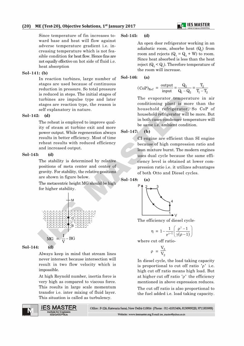
Sol–148: (a)2 3
4
1 V
P
The efficiency of diesel cycle-
= 11 11
1r
where cut off ratio-
= 3
2
VV
In diesel cycle, the load taking capacityis proportional to cut off ratio ' ' i.e.high cut off ratio means high load. Butat higher cut off ratio ' ' the efficiencymentioned in above expression reduces.The cut off ratio is also proportional tothe fuel added i.e. load taking capacity.

IES M
ASTER
(21) ME (Test-20), Objective Solutions, 1st January 2017
Sol–149: (c)
In simple bending, strain in bent beamvaries linearly across the beam depth
NA
Cross-section of a beam
Strain diagram
The stress is proportional to the strain isvalid upto proportional limit not elastic limit.
Sol–150. (d)Moment of resistance, MOR = Z
where Z is sectional modulusMOR = fy · ZMOR Z
Z of I-section is more than Z of rectangularsection hence assertion is wrong.
Sol–151: (d)The cam in contact of follower is case ofsuccessfully constraint. Because springforce is required to maintain the contact.This spring force does not guarantee thecontact all time because after certainspeed, the follower losses contact withcam due to inertia force.
Sol–152: (a)
A link moving on a rotating linkexperiences coriolis acceleration i.e. linkB experiences coriolis accelerations. Thereason for this component of accelerationis movement of block B in slot of A. Themagnitude of this acceleration-
= 2V
where V is velocity of block B and ' ' isrotation of link A.
Sol–153: (b)Sol–154: (b)
Over-running or reversible drive meansin the worm and worm wheel can driveeach other and prevent the damage thatcan occur if the driving power is cutsuddenly as mostly worm is the driver.
Sol–155: (a)Sol–156: (a)
The shaper is unsuitable for generatingflat surfaces on very large parts becauseof limitations on the stroke andoverhang of the arm. This problem issolved in the planer by applying thelinear primary motion to the workpieceand feeding the tool at right angles tothis motion. The primary motion isnormally accomplished by a rack andpinion drive using a variable speedmotor.Shapers are commonly used to machineflat surface on small components andare only suitable for low-batchquantities.
Sol–157: (c)Only the crystal structure of solvent isretained in a solid solution. The solutemust dissolve in the crystal structure ofsolvent.
Sol–158: (c)The atomic radius of carbon is smallerthan that of iron. So, carbon would forman interstitial solid solution with iron.So, reason is wrong.
Sol–159: (a)Sol–160: (b)