ESC 301 - Load rating of underbridges
16
TN 075: 2014 A3649717 Asset Standards Authority © State of NSW through Transport for NSW Page 1 of 7 For queries regarding this document [email protected] www.asa.transport.nsw.gov.au Technical Note TN 075: 2014 Issued date 23 October 2014 Effective date 23 October 2014 Subject: Updated requirements for load rating of underbridges This technical note is issued by the Asset Standards Authority as an update to RailCorp standard ESC 301 Load Rating of Underbridges, Version 2.3. The update includes general scope inclusions, loading diagram clarifications, reporting requirements and interpretation guides. The requirements of ESC 301 shall be replaced with the contents of this technical note as detailed below: 1. Purpose, scope and application Replace the first sentence with the following: This document sets out the criteria for load rating of all underbridges on the RailCorp network. 5.2 Live load Replace all bullet points and the last paragraph with the following: Heavy Coal [HC] – based on 3/(90 Class) locomotives plus 120 tonne (NHRH) coal wagons Main Line Freight [MF] – based on 3/(82 Class) locomotives plus 100 tonne (NHGF) coal wagons XPT/Explorer [XP] Suburban Electric [SE] Waratah Electric [WE] Track Laying Machine [TLM] – leading crawler track loadings in operating mode Superseded by T HR CI 12008 ST
Transcript of ESC 301 - Load rating of underbridges
Technical Note - TN 068: 2015
For queries regarding this document
[email protected] www.asa.transport.nsw.gov.au
Technical Note - TN 068: 2015 Issued date: 21 October 2015
Effective date: 21 October 2015
Subject: Withdrawal of ESC 301 Load Rating of Underbridges
This technical note is issued by the Asset Standards Authority as a notification to remove from
use RailCorp document ESC 301 Load Rating of Underbridges, Version 2.3, and its appending
technical note TN 075: 2014.
The essential content in ESC 301 and TN 075: 2014 has been incorporated in to ASA standard
T HR CI 12008 ST Load Rating of Underbridges, Version 1.0.
Authorisation:
Technical content prepared by
Checked and approved by
Interdisciplinary coordination checked by
Authorised for release
Signature
Date
Name Mel O'Sullivan Richard Hitch John Paff Graham Bradshaw
Position Principal Engineer Structures and Bridges
Lead Civil Engineer A/Chief Engineer Rail Director Network Standards and Services
© State of NSW through Transport for NSW Page 1 of 1
TN 075: 2014
A3649717 Asset Standards Authority © State of NSW through Transport for NSW Page 1 of 7
For queries regarding this document [email protected]
www.asa.transport.nsw.gov.au
Technical Note TN 075: 2014
Issued date 23 October 2014 Effective date 23 October 2014
Subject: Updated requirements for load rating of underbridges
This technical note is issued by the Asset Standards Authority as an update to RailCorp
standard ESC 301 Load Rating of Underbridges, Version 2.3. The update includes general
scope inclusions, loading diagram clarifications, reporting requirements and interpretation
guides. The requirements of ESC 301 shall be replaced with the contents of this technical note
as detailed below:
1. Purpose, scope and application Replace the first sentence with the following:
This document sets out the criteria for load rating of all underbridges on the RailCorp network.
5.2 Live load Replace all bullet points and the last paragraph with the following:
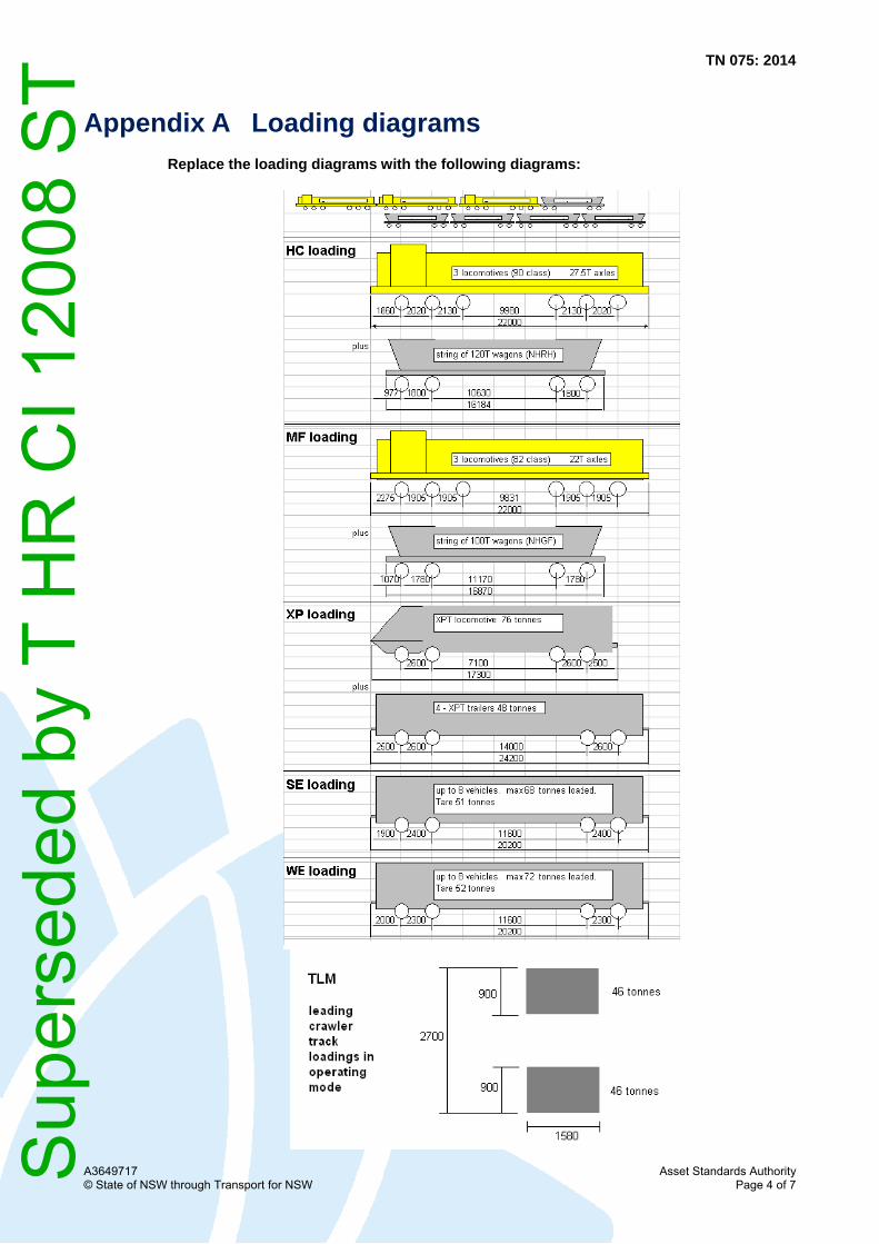
Heavy Coal [HC] – based on 3/(90 Class) locomotives plus 120 tonne (NHRH) coal
wagons
Main Line Freight [MF] – based on 3/(82 Class) locomotives plus 100 tonne (NHGF) coal
wagons
XPT/Explorer [XP]
Suburban Electric [SE]
Waratah Electric [WE]
Track Laying Machine [TLM] – leading crawler track loadings in operating mode
Sup
erse
ded
by T
HR
CI 1
2008
ST
TN 075: 2014
A3649717 Asset Standards Authority © State of NSW through Transport for NSW Page 2 of 7
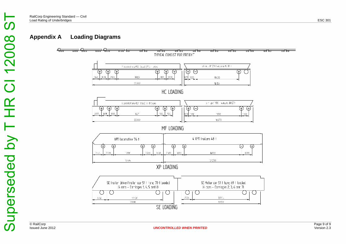
Appendix A contains a diagrammatic representation of the above train consists. The rolling
stock codes shown in parentheses (for example NHGF) are referenced from the ASA Train
Operating Conditions (TOC) manual. The overall vehicle length dimensions shown are
measured to the vehicle coupler pulling faces in millimetres.
5.4 Dynamic load allowance Add the following sentence:
The minimum value of DLA shall be not less than 0.1.
8. Rating results Delete the first sentence.
Replace the last sentence with the following:
The layout for the presentation of the rating results is outlined in Appendix B and Appendix C.
9.1 General Add the following sentence after the last paragraph:
All relevant material strengths, section losses, material factors, loads, load factors, DLA's, wind
speeds, fatigue criteria etc and any assumptions shall be clearly shown in a table.
9.2 Wrought iron test requirements Add the following sentence after the last paragraph:
Ultimate strength shall be calculated similarly.
9.3.1 Executive summary Delete table.
Replace text within the parentheses with the following:
(see Appendix B for the layout).
9.3.2 Engineering details Delete table.
Replace text within the parentheses with the following:
(see Appendix C for the layout).
Sup
erse
ded
by T
HR
CI 1
2008
ST
TN 075: 2014
A3649717 Asset Standards Authority © State of NSW through Transport for NSW Page 3 of 7
9.3.3 Appendices Add the following bullet point:
specific train consist axle load configurations that are referenced and that are not
included in Appendix A or AS 5100 shall be shown diagrammatically.
Insert new Section 10 as per below:
10 Interpretation guides ESC 301 is presented as a legacy RailCorp document and shall be read in conjunction with and
interpreted according to the interpretation guidelines published:
Reference No Title Version Issue date TS 10762 Legacy RailCorp Standards Interpretation -
Management Overview 1.0 28/06/2013
TS 10760 Guide to interpretation of organisational role and process references in RailCorp standards
1.0 17/06/2013
TS 10760 - SMS Interpretation guide RailCorp SMS References within RailCorp engineering standards
1.0 17/06/2013
Sup
erse
ded
by T
HR
CI 1
2008
ST

A3649717 Asset Standards Authority © State of NSW through Transport for NSW Page 4 of 7
Appendix A Loading diagrams Replace the loading diagrams with the following diagrams:
TN 075: 2014 S
uper
sede
d by
T H
R C
I 120
08 S
T

TN 075: 2014
A3649717 Asset Standards Authority © State of NSW through Transport for NSW Page 5 of 7
Insert new Appendix B and C after Appendix A as per below:
Appendix B Bridge load rating executive summary table (sample layout) The bridge load rating executive summary table below provides an example of criteria required for load rating assessment. The text in italics indicates
information the assessor would capture.
Bridge & Type: Central Road Underbridge Location: Central Route & Tracks: Main Suburban: Up Main & Down Main Km: 1.000 km Design drawing load capacity: M270
Critical bridge components for nominated rating vehicles
300LA (2) MF (2)
As New As Is As New As Is
Bridge member or connection or critical section (1)
Design action (1)
As Is section loss (% & element)
Rating factor (RF)
Load rating (LR)
Rating factor (RF)
Load rating (LR)
Load rating without DLA (α=0.1)
Reduced speed for RF=1 (If applicable)
Rating factor (RF)
Load rating (LR)
Rating factor (RF)
Load rating (LR)
Load rating without DLA (α=0.1)
Reduced speed for RF=1 (If applicable)
Main girder Moment 10% bottom
1.25 375LA 1.20 360LA 439LA N/A 1.75 1.75MF 1.7 1.7MF 2.3MF N/A
flange Main girder Shear 20% web
thickness 1.00 300LA
0.91 273LA
(4) 305LA
41km/h 1.4 1.4MF 1.3 1.3MF (4)
1.6MF N/A
(1) The critical bridge structural member or connection or section with the critical design actions shall be included for each reference vehicle.
(2) Additional columns or tables can be added or deleted for the nominated rating vehicles and bridge specific items and actions.
(3) Additional rows can be added to note load rating subsequent to any bridge component proposed strengthening or repair.
(4) Critical load rating(s) shall be highlighted. In the example above load critical rating entries are in bold text.
Sup
erse
ded
by T
HR
CI 1
2008
ST
TN 075: 2014
A3649717 Asset Standards Authority © State of NSW through Transport for NSW Page 6 of 7
Appendix C Bridge load rating engineering assessment summary table (sample layout)
The bridge load rating engineering assessment table below provides an example of criteria required for load rating assessment. The text in italics
indicates information the assessor would capture.
Assessment Type: Ultimate Limit State (ULS) As New & As Is [or Serviceability Limit State (SLS) As New & As Is etc] Bridge & Type: Central Road Underbridge Location: Central Route & Tracks Carried: Main Suburban: Up Main & Down Main Km: 1.000 km Design drawing load capacity: M270 Nominated Rating Vehicle (LRV): 300LA
Bridge component (1)
Critical design
(2)action
Member length (L)
As Is Section loss (% & element)
Capacity reduction factor (Φ)
As New Design capacity (ΦRu)
As Is Design capacity (ΦRu)
Dead load factor (γg)
Super imposed dead load factor (γgs)
Factored permanent load effects PE [γgSg*+ γgsSgs*+ Sp*+Ss*+St
*]
As New Available capacity for live load effects [ΦRu-PE]
As Is Available capacity for live load effects [ΦRu-PE]
Live load factor (γL)
Dynamic load allowance (α)
Multiple track factor (W)
Factored live load effects [γL(1+α)W(
(3)S*L)]
As New As Is
Rating factor (RF) (3)
Load rating (LR) (3)
Rating factor (RF) (3)
Load rating (LR) (3)
Load rating without DLA (α=0.1)(3)
Reduced speed for RF=1 (If applicable) (3)
Main girder Moment 20m 10% bottom flange
0.9 3960kNm 3600kNm 1.1 1.4 600kNm 3360kNm 3000kNm 1.6 0.34 1.00 2500kNm 1.25 375LA 1.20 360LA 439LA
Main girder Shear 20m 20% web thickness 0.9 1360kN 1260kN 1.1 1.4 260kN 1100kN 1000kN 1.6 0.23 1.00 1100kN 1.00 300LA 0.91 273LA
(4) 305LA 41km/h (4)
Longitudinal Stringer
Primary X gird er Primary X girder to Main Girder rivets
Primary X girder to Main girder cleats
End cross gird er Sway b racing Wind bracing De ck slab B earing Trestle Headstock Pier Pi le cap Abu tment Abutment foundation
Pier foundation Piles
LOWEST RATING (4) 1.00 300LA 0.91 273LA (4) 305LA 41km/h (4)
(1) All relevant structural members and connections and critical sections shall be included. (Examples shown only)
(2) Actions shall include AS 5100.2 railway traffic relevant possibilities such as moment, shear, torsion, axial, centrifugal, braking, traction, nosing, lateral, derailment, wind, combinations etc.
(3) Additional columns or tables can be added for other nominated rating vehicles and bridge specific items.
(4) The critical load rating(s) shall be highlighted. In the example above critical load rating entries are in bold text.
Sup
erse
ded
by T
HR
CI 1
2008
ST

TN 075: 2014
Authorisation
Signature
Technical content prepared by
Checked and approved by
Interdisciplinary coordination checked by
Authorised for release
Name Malcolm Peake Richard Hitch David Spiteri Graham Bradshaw
Position Senior Engineer Structures
Lead Civil Engineer Chief Engineer Rail Principal Manager Network Standards & Services
Asset Standards Authority A3649717 © State of NSW through Transport for NSW Page 7 of 7
Sup
erse
ded
by T
HR
CI 1
2008
ST
LOAD RATING OF UNDERBRIDGES
ESC 301
Engineering Standard Civil
Engi
neer
ing
Stan
dard
Version 2.3
Issued June 2012
Owner: Chief Engineer Civil
Approved John Stapleton Authorised Richard Hitch by: Principal Engineer Technology by: Chief Engineer Civil
& Standards Civil
Disclaimer This document was prepared for use on the RailCorp Network only. RailCorp makes no warranties, express or implied, that compliance with the contents of this document shall be sufficient to ensure safe systems or work or operation. It is the document user’s sole responsibility to ensure that the copy of the document it is viewing is the current version of the document as in use by RailCorp. RailCorp accepts no liability whatsoever in relation to the use of this document by any party, and RailCorp excludes any liability which arises in any manner by the use of this document. Copyright The information in this document is protected by Copyright and no part of this document may be reproduced, altered, stored or transmitted by any person without the prior consent of RailCorp.
UNCONTROLLED WHEN PRINTED Page 1 of 9 Sup
erse
ded
by T
HR
CI 1
2008
ST
RailCorp Engineering Standard — Civil Load Rating of Underbridges ESC 301
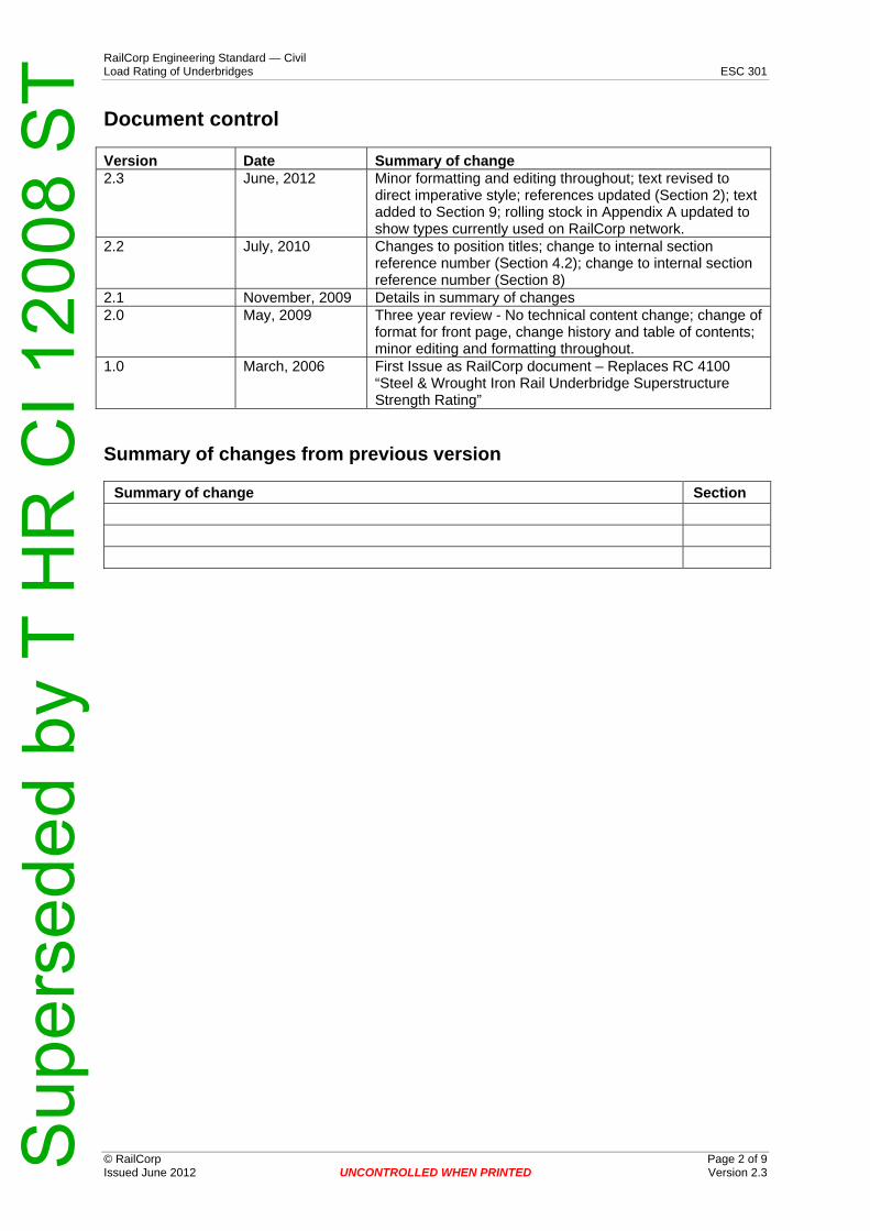
Document control
© RailCorp Page 2 of 9 Issued June 2012 UNCONTROLLED WHEN PRINTED Version 2.3
Version Date Summary of change 2.3 June, 2012 Minor formatting and editing throughout; text revised to
direct imperative style; references updated (Section 2); text added to Section 9; rolling stock in Appendix A updated to show types currently used on RailCorp network.
2.2 July, 2010 Changes to position titles; change to internal section reference number (Section 4.2); change to internal section reference number (Section 8)
2.1 November, 2009 Details in summary of changes 2.0 May, 2009 Three year review - No technical content change; change of
format for front page, change history and table of contents; minor editing and formatting throughout.
1.0 March, 2006 First Issue as RailCorp document – Replaces RC 4100 “Steel & Wrought Iron Rail Underbridge Superstructure Strength Rating”
Summary of changes from previous version
Summary of change Section
Sup
erse
ded
by T
HR
CI 1
2008
ST
RailCorp Engineering Standard — Civil Load Rating of Underbridges ESC 301
© RailCorp Page 3 of 9 Issued June 2012 UNCONTROLLED WHEN PRINTED Version 2.3
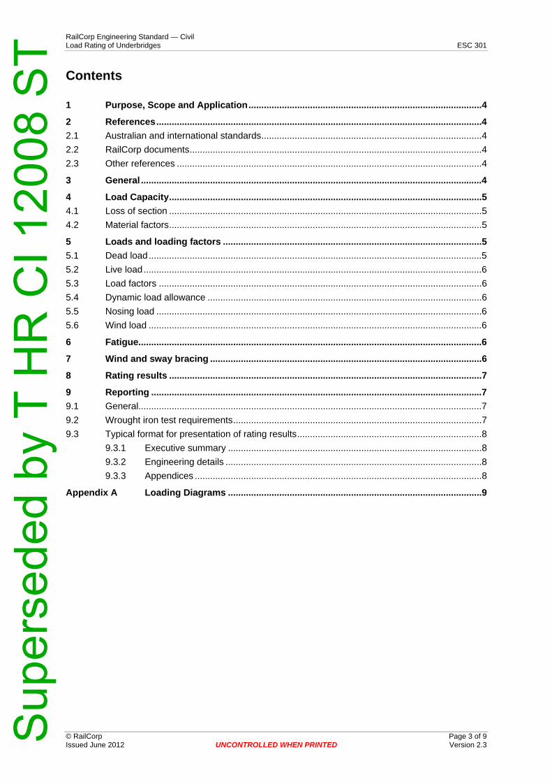
Contents
1 Purpose, Scope and Application...........................................................................................4 2 References...............................................................................................................................4 2.1 Australian and international standards......................................................................................4 2.2 RailCorp documents..................................................................................................................4 2.3 Other references .......................................................................................................................4 3 General .....................................................................................................................................4 4 Load Capacity..........................................................................................................................5 4.1 Loss of section ..........................................................................................................................5 4.2 Material factors..........................................................................................................................5 5 Loads and loading factors .....................................................................................................5 5.1 Dead load..................................................................................................................................5 5.2 Live load....................................................................................................................................6 5.3 Load factors ..............................................................................................................................6 5.4 Dynamic load allowance ...........................................................................................................6 5.5 Nosing load ...............................................................................................................................6 5.6 Wind load ..................................................................................................................................6 6 Fatigue......................................................................................................................................6 7 Wind and sway bracing ..........................................................................................................6 8 Rating results ..........................................................................................................................7 9 Reporting .................................................................................................................................7 9.1 General......................................................................................................................................7 9.2 Wrought iron test requirements.................................................................................................7 9.3 Typical format for presentation of rating results........................................................................8
9.3.1 Executive summary ...................................................................................................8 9.3.2 Engineering details ....................................................................................................8 9.3.3 Appendices ................................................................................................................8
Appendix A Loading Diagrams ...................................................................................................9
Sup
erse
ded
by T
HR
CI 1
2008
ST
RailCorp Engineering Standard — Civil Load Rating of Underbridges ESC 301
© RailCorp Page 4 of 9 Issued June 2012 UNCONTROLLED WHEN PRINTED Version 2.3
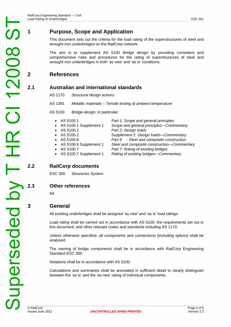
1 Purpose, Scope and Application This document sets out the criteria for the load rating of the superstructures of steel and wrought iron underbridges on the RailCorp network.
The aim is to supplement AS 5100 Bridge design by providing consistent and comprehensive rules and procedures for the rating of superstructures of steel and wrought iron underbridges in both ‘as new’ and ‘as is’ conditions.
2 References
2.1 Australian and international standards AS 1170 Structural design actions
AS 1391 Metallic materials – Tensile testing at ambient temperature
AS 5100 Bridge design, in particular:
• AS 5100.1 Part 1: Scope and general principles • AS 5100.1 Supplement 1 Scope and general principles—Commentary • AS 5100.2 Part 2: Design loads • AS 5100.2 Supplement 2 Design loads—Commentary • AS 5100.6 Part 6 : Steel and composite construction • AS 5100.6 Supplement 1 Steel and composite construction—Commentary • AS 5100.7 Part 7: Rating of existing bridges • AS 5100.7 Supplement 1 Rating of existing bridges—Commentary
2.2 RailCorp documents ESC 300 Structures System
2.3 Other references Nil
3 General All existing underbridges shall be assigned ‘as new’ and ‘as is’ load ratings.
Load rating shall be carried out in accordance with AS 5100; the requirements set out in this document; and other relevant codes and standards including AS 1170.
Unless otherwise specified, all components and connections (including splices) shall be analysed.
The naming of bridge components shall be in accordance with RailCorp Engineering Standard ESC 300.
Notations shall be in accordance with AS 5100.
Calculations and summaries shall be annotated in sufficient detail to clearly distinguish between the ‘as is’ and the ‘as new’ rating of individual components.
Sup
erse
ded
by T
HR
CI 1
2008
ST

RailCorp Engineering Standard — Civil Load Rating of Underbridges ESC 301
© RailCorp Page 5 of 9 Issued June 2012 UNCONTROLLED WHEN PRINTED Version 2.3
4 Load Capacity
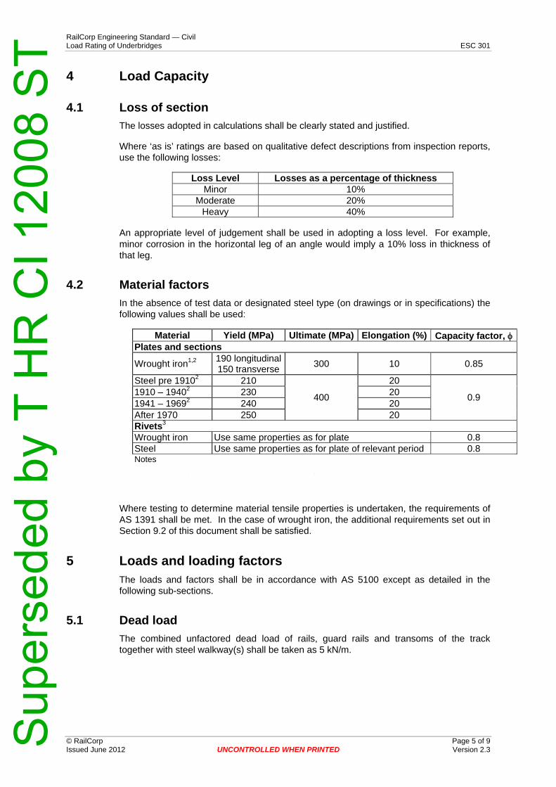
4.1 Loss of section The losses adopted in calculations shall be clearly stated and justified.
Where ‘as is’ ratings are based on qualitative defect descriptions from inspection reports, use the following losses:
Loss Level Losses as a percentage of thickness Minor 10%
Moderate 20%Heavy 40%
An appropriate level of judgement shall be used in adopting a loss level. For example, minor corrosion in the horizontal leg of an angle would imply a 10% loss in thickness of that leg.
4.2 Material factors In the absence of test data or designated steel type (on drawings or in specifications) the following values shall be used:
Material Yield (MPa) Ultimate (MPa) Elongation (%) Capacity factor, φPlates and sections
Wrought iron1,2 190 longitudinal150 transverse 300 10 0.85
Steel pre 19102 210
400
20
0.9 1910 – 19402 230 20 1941 – 19692 240 20 After 1970 250 20 Rivets3
Wrought iron Use same properties as for plate 0.8 Steel Use same properties as for plate of relevant period 0.8 Notes 1. Plastic properties shall not to be used if elongation < 5% 2. Reduce yield by 5% where sections > 20mm thickness are used 3. Field/hand driven rivets are assumed to be equivalent to shop rivets.
Where testing to determine material tensile properties is undertaken, the requirements of AS 1391 shall be met. In the case of wrought iron, the additional requirements set out in Section 9.2 of this document shall be satisfied.
5 Loads and loading factors The loads and factors shall be in accordance with AS 5100 except as detailed in the following sub-sections.
5.1 Dead load The combined unfactored dead load of rails, guard rails and transoms of the track together with steel walkway(s) shall be taken as 5 kN/m.
Sup
erse
ded
by T
HR
CI 1
2008
ST

RailCorp Engineering Standard — Civil Load Rating of Underbridges ESC 301
© RailCorp Page 6 of 9 Issued June 2012 UNCONTROLLED WHEN PRINTED Version 2.3
5.2 Live load The rating shall be derived from calculations based on the 300LA design loading as described in AS 5100, and it shall include the 360 kN front axle of the simulated locomotive. The worst load effect shall be considered.
Ratings shall be specified in terms of current trains operating on the network. Below is a list of main line train consists on the RailCorp network:
• Heavy coal (HC) – based on 3/90 class locomotives plus 120 tonne NHRH coal wagons
• Main Line freight (MF) – based on main line (82 class) locomotives plus 100 tonne NHGF coal wagons
• XPT/Explorer (XP) • Suburban Electric (SE) – worst combination of suburban vehicles, i.e. Waratah
fleet.
Appendix A contains a diagrammatic representation of these train consists.
5.3 Load factors Load factors for dead loads and railway traffic (live load) shall be in accordance with Table 7.3 of AS 5100.7.
Where the load carrying capacity rating of a component or connection is less than unity (1.0), the load factor for live load (LL) shall be calculated based on rating being equal to unity (1.0).
For example, if rating = 0.8 with LL load factor = 1.4, then LL load factor will be less than 1.4 for rating = 1.0.
The Chief Engineer Civil shall determine if a load factor lower than the value specified in AS 5100 is acceptable.
5.4 Dynamic load allowance The dynamic load allowance (DLA) used in the load rating assessment of railway underbridges shall be in accordance with AS 5100.2.
5.5 Nosing load Nosing load shall be in accordance with AS 5100.2.
5.6 Wind load A serviceability wind speed of 20 m/s shall be used in the load rating assessment of railway underbridges.
6 Fatigue Rating of railway underbridges in terms of fatigue shall be undertaken in accordance with AS 5100.7.
7 Wind and sway bracing The wind and sway bracing on old steel structures consists of flat bars and angles, which are generally found not to have adequate theoretical capacity for current rail traffic.
Sup
erse
ded
by T
HR
CI 1
2008
ST

RailCorp Engineering Standard — Civil Load Rating of Underbridges ESC 301
© RailCorp Page 7 of 9 Issued June 2012 UNCONTROLLED WHEN PRINTED Version 2.3
However, there is no evidence that the bracing is being overloaded. When calculating the rating, load effects arising from dynamic load allowance are not applied to the bracing.
The rating of these components will generally be less than one. The rating report shall include recommendations on the appropriate maintenance strategy; that is, inspection frequency, intervention levels and response times necessary to maintain safety.
8 Rating results The results of the load rating shall be expressed as the ratio of member capacity over applied load.
They are to be tabulated for ‘as new’ and ‘as is’; and with and without full DLA.
The type of vehicles and the effect of any speed restrictions that are in force, or that are proposed, are to be shown.
Where the rating is less than unity (1.0), the following information shall also be included:
• the reduced speed required to increase the rating to unity (1.0); that is, the reduction to DLA with respect to a reduced speed; and
• the calculated load factor for live load with full DLA.
The results of the fatigue analysis shall also be provided.
A typical layout for the presentation of the rating results is outlined in Section 9.3 of this document.
9 Reporting
9.1 General A written report based on the results of the load rating shall be prepared. The report shall comprise: an executive summary; engineering details; and appendices.
The report shall include a general arrangement layout drawing of the bridge showing the arrangement of the main bridge components and the span layout.
9.2 Wrought iron test requirements The reporting of test results for wrought iron structures shall include:
• tensile properties; • Charpy values; • origin of sample (i.e. name of location); • sample location size and orientation (e.g. transverse); • date of manufacture (or best estimate); • temperature (for Charpy tests); and • extensometer charts (for tensile tests)
All test results shall be collated with existing records.
Yield strength shall be determined using test results. The average and the standard deviation shall be calculated; and the yield strength shall be taken as the average yield strength minus two times the standard deviation (i.e. YS = meanYS – 2SD).
Sup
erse
ded
by T
HR
CI 1
2008
ST
RailCorp Engineering Standard — Civil Load Rating of Underbridges ESC 301
© RailCorp Issued June
Page
e 8 of 9 r 2.3sionV 2012 UNCONTROLLED WHEN PRINTED
9.3 Typical format for presentation of rating results
9.3.1 Executive summary The executive summary typically comprises a brief description of the railway underbridge; a table that summarizes the results of the load rating assessment (see below for an example of a layout); and a summary of conclusions and recommendations.
Bridge Superstructure Member Rating (Speed > 80km/hr) Main Long. Girder Primary X Girder Secondary X Girder Secondary Long. Stringer
3.13 1.10 1.14 1.01
9.3.2 Engineering details The engineering details are typically a more in depth narrative of the load rating assessment activity. The description of the railway underbridge is provided in greater detail. The methodologies for the load rating assessment and fatigue assessment are clearly described and include a summary of live load cases used in the assessments. The results are tabled in much greater detail (see below for an example of a layout).
Superstructure Connection Rating (Speed > 80km/hr) Primary X Girder
To Main Box Girder
(Bolts)
Long. Stringer to
Primary X Girder (Rivets)
Secondary X Girder to Main Box Girder Complete Connection One Failed Web Cleat
Rivets Cleats Rivets Cleats
5.11 1.08 1.06 1.11 1.04 1.01
9.3.3 Appendices The appendices include the following items:
• photographs of the underbridge (an elevation shot and a shot along tracks); • bridge capacity; • load effect summary; • inspection summary; • theoretical fatigue damage; and • an engineering drawing showing the general arrangement of the underbridge
Sup
erse
ded
by T
HR
CI 1
2008
ST

RailCorp Engineering Standard — Civil Load Rating of Underbridges ESC 301
Appendix A Loading Diagrams
© RailCorp Page 9 of 9 Issued June 2012 UNCONTROLLED WHEN PRINTED Version 2.3 S
uper
sede
d by
T H
R C
I 120
08 S
T