EOLO STAR 24 3 E - Apie mus 3 - IE INSTALLATOR USER TECHNICIAN 1 BOILER INSTALLATION. 1.1...
28
EOLO STAR 24 3 E *1.032131IE* Instruction booklet and warning IE
Transcript of EOLO STAR 24 3 E - Apie mus 3 - IE INSTALLATOR USER TECHNICIAN 1 BOILER INSTALLATION. 1.1...

EOLO STAR24 3 E
*1.032131IE*
Instruction booklet and warning IE
Dear Customer,Our compliments for having chosen a top-quality Immergas product, able to assure well-being and safety for a long period of time. As an Immergas customer you can also count on a qualified after-sales service, prepared and updated to guarantee constant efficiency of your boiler. Read the following pages carefully: you will be able to draw useful suggestions regarding the correct use of the appliance, the respect of which, will confirm your satisfaction for the Immergas product. Contact our area authorised after-sales centre as soon as possible to request commissioning. Our technician will verify the correct functioning conditions; he will perform the necessary calibrations and will demonstrate the correct use of the generator. For any interventions or routine maintenance contact Immergas Authorised Centres: these have original spare parts and boast of specific preparation directly from the manufacturer.
General recommendationsThe instruction book is an integral and essential part of the product and must be consigned to the new user also in the case of transfer or succession of ownership. It must be kept well and consulted carefully, as all of the warnings supply important indications for safety in the installation, use and maintenance stages. In compliance with legislation in force, the systems must be designed by qualified professionals, within the dimensional limits established by the Law. Installation and maintenance must be performed in compliance with the regulations in force, according to the manufacturer’s instructions and by professionally qualified staff, intending staff with specific technical skills in the plant sector, as envisioned by the Law. Incorrect installation can cause injury to persons and animals and damage to objects, for which the manufacturer is not liable. Maintenance must be carried out by skilled technical staff. The Immergas Authorised After-sales Service represents a guarantee of qualifications and professionalism. The appliance must only be destined for the use for which it has been expressly declared. Any other use will be considered improper and therefore potentially dangerous. If errors occur during installation, running and maintenance, due to the non compliance of technical laws in force, standards or instructions contained in this book (or however supplied by the manufacturer), the manufacturer is excluded from any contractual and extra-contractual liability for any damages and the appliance warranty is invalidated. For further information regarding legislative and statutory provisions relative to the installation of gas heat generators, consult the Immergas site at the following address: www.immergas.com
INDICEUSER pag.
Immergas S.p.A. declines all liability due to printing or transcription errors, reserving the right to make any modifications to its technical and commercial documents without forewarning.
INSTALLATOR pag. TECHNICIAN pag.
DECLARATION OF CONFORMITYFor the purpose and effect of the 2009/142/CE Gas Appliance Directive, 2004/108/CE EMC Directive, 92/42/CE Efficiency Directive and 2006/95/CE Low Voltage Directive.The Manufacturer: Immergas S.p.A. v. Cisa Ligure n° 95 42041 Brescello (RE)DECLARES THAT: the Immergas boiler model: Eolo Star 24 3 E is in compliance with the same European Community Directives
Signature:
Mauro Guareschi
Research & Development Director
1 Boiler installation. ..................................... 31.1 Installation recommendations. ................ 31.2 Main dimensions. ...................................... 41.3 Main dimensions
recessing kit (optional). ............................ 41.4 Anti-freeze protection. ............................. 41.5 Attachments. .............................................. 41.6 Remote controls and room
chronothermostats (optional). ................ 51.7 Immergas flue systems. ............................. 61.8 Outdoor installation in
partially protected area. ........................... 61.9 Outdoor installation using recessed frame
(with direct air intake). ............................. 61.10 Indoor installation. ................................... 91.11 Fume exhaust to flue/chimney...............131.12 Ducting of existing flues. ........................131.13 Flues, chimneys and chimney caps. ......131.14 System filling. ...........................................131.15 Gas system start-up. ................................131.16 Boiler start up (ignition). .......................131.17 Circulation pump. ...................................131.18 Kits available on request. ........................141.19 Boiler components. .................................14
2 Instructions for use and maintenance. .152.1 Cleaning and maintenance. ...................152.2 General warnings. ...................................152.3 Control panel. ..........................................152.4 Fault and anomaly signals. .....................162.5 Restore heating system pressure............162.6 Draining the system. ...............................162.7 Anti-freeze protection. ...........................162.8 Case cleaning. ..........................................172.9 Decomissioning. ......................................17
3 Boiler start-up. (Initial check) ...........................................18
3.1 Hydraulic layout. .....................................183.2 Wiring diagram. ......................................193.3 Troubleshooting. .....................................193.4 Converting the boiler to other types of
gas. .............................................................193.5 Checks following conversion to another
type of gas. ................................................203.6 Possible adjustments. ..............................203.7 Programming the p.C.B .........................203.8 Automatic slow ignition function with
timed ramp delivery. ...............................213.9 “Chimney sweep function”. ....................213.10 Heating timer. ..........................................213.11 Pump anti-block function. .....................213.12 Funzione antitrafila circuito sanitario. .213.13 Radiators anti-freeze function. ..............213.14 P.C.B. Periodical self-check. ...................213.15 Casing removal. .......................................223.16 Yearly appliance check
and maintenance. ....................................223.17 Variable heat power. ................................243.18 Combustion parameters. ........................243.19 Technical data. .........................................25

1-1
3 - IE
INST
ALL
ATO
RU
SER
TECH
NIC
IAN
1 BOILER INSTALLATION.
1.1 INSTALLATION RECOMMENDATIONS.
The Eolo Star 24 3 boiler has been designed for wall mounted installation or installation inside the wall using the recessed frame provided; they must be used to heat environments, to produce hot water and similar purposes. In the case of wall installation the wall surface must be smooth, without any protrusions or recesses enabling access to the rear part. They are NOT designed to be installed on plinths or floors (Fig. 1-1).By varying the type of installation the classifica-tion of the boiler also varies, precisely:
- Indoor installation: - without the 2 intake caps and with upper
casing. exhaust terminal Ø80 (configuration type B22);
- without upper casing and with concentric terminals and separators (configuration type C).
- Outdoor installation in partially protected areas:
- without the 2 intake caps and with upper casing. Exhaust terminal Ø80 (configuration type C);
- the upper casing is recommended but not obligatory with concentric terminals and separators (this configuration is also type C).
- Outdoor installation with recess frame: - using the spacers under the side plugs of the
sealed chamber (configuration type C); - leave the plugs of the sealed chamber
mounted and use the concentric pipes or other types of pipes suitable for the sealed chamber for air intake and fume exhaustion (configuration type C).
Only professionally qualified heating/plumbing technicians are authorised to install Immergas gas appliances. Installation must be carried out according to the standards, current legislation and in compliance with local technical regu-lations and the required technical procedures. Installation of the Eolo star 24 3 E boiler when powered by LPG must comply with the rules regarding gases with a greater density than air (remember, as an example, that it is prohibited to install plants powered with the above-mentioned gas in rooms where the floor is at a lower quota that the average external country one). Before installing the appliance, ensure that it is delive-red in perfect condition; if in doubt, contact the supplier immediately. Packing materials (staples, nails, plastic bags, polystyrene foam, etc.) consti-tute a hazard and must be kept out of the reach of children. If the appliance is installed inside or between cabinets, ensure sufficient space for normal servicing; therefore it is advisable to le-ave clearance of at least 3 cm between the boiler casing and the vertical sides of the cabinet. Leave adequate space above the boiler for possible water and fume removal connections.Keep all flammable objects away from the ap-pliance (paper, rags, plastic, polystyrene, etc.). Do not place household appliances underneath the boiler as they could be damaged if the sa-fety valve intervenes (if not conveyed away by a discharge funnel), or if there are leaks from the hydraulic connections; on the contrary, the manufacturer cannot be held responsible for any damage caused to the household appliances.
In the event of malfunctions, faults or incorrect operation, turn the appliance off immediately and contact a qualified technician (e.g. the Immergas Technical After-Sales Centre, which has specifi-cally trained staff and original spare parts) Do not attempt to modify or repair the appliance alone. Failure to comply with the above implies personal responsibility and invalidates the warranty.• Installation regulations: this boiler can be in-
stalled outdoors in a partially protected area. A partially protected area is one in which the appliance is not exposed to the direct action of the weather (rain, snow, hail, etc...). If necessary it is possible to install the boiler in positions totally exposed to the direct action of the we-ather using only the cover kit (Optional) The boiler can be installed inside a wall using the appropriate recessed frame (Optional).
Important: Wall mounting of the boiler on the wall or inside the wall must guarantee stable and efficient support for the generator. The recessed frame kit (Optional) guarantees an adequate support only if installed correctly (in accordance with the code of practice) following the instructions on the instruction leaflet. The recessed frame for the Eolo Star 24 3 E boiler is not a supporting structure and must not replace the wall removed. It is necessary to position the boiler inside the wall. For safety reasons against any leaks it is necessary to plaster the boiler housing in the brick wall.The plugs (standard supply) are to be used only in conjunction with the mounting brackets or fixing template to fix the appliance to the wall; they only ensure adequate support if inserted correctly (according to technical standards) in walls made of solid or semi-hollow brick or block. In the case of walls made from hollow brick or block, partitions with limited static properties, or in any case walls other than those indicated, a static test must be carried out to ensure adequate support.
N.B.: the hex head screws supplied in the blister pack are to be used exclusively to fix the relative mounting bracket to the wall.
These boilers are used to heat water to below boiling temperature in atmospheric pressure.They must be attached to a heating system sui-table for their capacity and voltage.
YES NO
1-3
1-2
4 - IE
INST
ALL
ATO
RU
SER
TECH
NIC
IAN
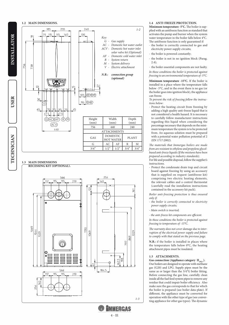
1.2 MAIN DIMENSIONS.
1.3 MAIN DIMENSIONS RECESSING KIT (OPTIONAL).
Key: G - Gas supply AC - Domestic hot water outlet ACV - Domestic hot water inlet
solar valve kit (Optional) AF - Domestic cold water inlet R - System return M - System delivery V - Electric attachment
N.B.: connection group (optional)
1.4 ANTI-FREEZE PROTECTION.Minimum temperature -5°C. The boiler is sup-plied with an antifreeze function as standard that activates the pump and burner when the system water temperature in the boiler falls below 4°C.The antifreeze function is only guaranteed if:- the boiler is correctly connected to gas and
electricity power supply circuits;- the boiler is powered constantly;- the boiler is not in no ignition block (Parag.
2.4);- the boiler essential components are not faulty.In these conditions the boiler is protected against freezing to an environmental temperature of -5°C.
Minimum temperature -15°C. If the boiler is installed in a place where the temperature falls below -5°C, and in the event there is no gas (or the boiler goes into ignition block), the appliance can freeze.To prevent the risk of freezing follow the instruc-tions below:- Protect the heating circuit from freezing by
adding a high quality anti-freeze liquid that is not considered a health hazard. It is necessary to carefully follow manufacturer instructions regarding this liquid when considering the percentage necessary that depends on the mini-mum temperature the system is to be protected from. An aqueous solution must be prepared with a potential water pollution potential of 2 (EN 1717:2002).
The materials that Immergas boilers are made from are resistant to ethylene and propylene glycol-based anti-freeze liquids (If the mixtures have been prepared according to industry standards).For life and possible disposal, follow the supplier’s instructions.- Protect the condensate drain trap and circuit
board against freezing by using an accessory that is supplied on request (antifreeze kit) comprising two electric heating elements, the relevant cables and a control thermostat (carefully read the installation instructions contained in the accessory kit pack).
Boiler anti-freezing protection is thus ensured only if:- the boiler is correctly connected to electricity
power supply circuits;- Main switch is inserted;- the anti-freeze kit components are efficient.In these conditions the boiler is protected against freezing to temperature of -15°C.
The warranty does not cover damage due to inter-ruption of the electrical power supply and failure to comply with that stated on the previous page.
N.B.: if the boiler is installed in places where the temperature falls below 0°C, the heating attachment pipes must be insulated.
1.5 ATTACHMENTS.Gas connection (Appliance category II2H3+).Our boilers are designed to operate with methane gas (G20) and LPG. Supply pipes must be the same as or larger than the 3/4”G boiler fitting. Before connecting the gas line, carefully clean inside all the fuel feed system pipes to remove any residue that could impair boiler efficiency. Also make sure the gas corresponds to that for which the boiler is prepared (see boiler data-plate). If different, the appliance must be converted for operation with the other type of gas (see conver-ting appliance for other gas types). The dynamic
Height(mm)
Width(mm)
Depth(mm)
756 440 240ATTACHMENTS
GAS DOMESTICHOT WATER PLANT
G AC AF R M3/4” 1/2” 1/2” 3/4” 3/4”

1-61-5
5 - IE
INST
ALL
ATO
RU
SER
TECH
NIC
IAN
gas supply (methane or LPG) pressure must also be checked according to the type used in the boiler, as insufficient levels can reduce generator output and cause malfunctions.Ensure correct gas cock connection. The gas supply pipe must be suitably dimensioned accor-ding to current regulations in order to guarantee correct gas flow to the boiler even in conditions of maximum generator output and to guarantee appliance efficiency (technical specifications). The coupling system must conform to standards.
Combustible gas quality. The appliance has been designed to operate with gas free of impurities; otherwise it is advisable to fit special filters up-stream from the appliance to restore the purity of the gas.Storage tanks (in case of supply from LPG depot).- New LPG storage tanks may contain residual
inert gases (nitrogen) that degrade the mixture delivered to the appliance casing functioning anomalies.
- Due to the composition of the LPG mixture, layering of the mixture components may occur during the period of storage in the tanks. This can cause a variation in the heating power of the mixture delivered to the appliance, with subsequent change in its performance.
Hydraulic attachment.Important: In order not to void the warranty before making the boiler connections, carefully clean the heating system on the primary heat exchanger (pipes, radiators, etc.) with special pickling or de-scaling products to remove any deposits that could compromise correct boiler operation.
In compliance with Standards in force it is man-datory to treat the water in the heating system chemically in order to protect the system and appliance from deposits of lime scale.
Water connections must be made in a rational way using the couplings on the boiler template. The boiler safety valves outlet must be connected to a draining funnel. Otherwise, the manufactu-rer declines any responsibility in case of flooding if the drain valves cut in.
Important: to preserve the duration of appliance efficiency features, in the presence of water whose features can lead to the deposit of lime scale, installation of the “polyphosphate dispenser” kit is recommended. On the basis of the Standards in force, it is mandatory to treat the water with over 25 French degrees in the heating circuit and over 15 French degrees for DHW using conditioning chemicals for powers < 100 kW or with softeners for powers > 100 kW.
Electrical connection: The “Eolo Star 24 3 E” boiler has an IPX5D protection rating for the entire appliance. Electrical safety of the unit is reached when it is correctly connected to an efficient earthing system as specified by current safety standards.
Important: Immergas S.p.A. declines any responsibility for damage or physical injury caused by failure to connect the boiler to an efficient earth system or failure to comply with the reference standards.
Also ensure that the electrical installation corresponds to maximum absorbed power specifications as shown on the boiler data-plate. The boilers are supplied complete with an “X” type power cable without plug. The power sup-ply cable must be connected to a 230V ±10% / 50Hz mains supply respecting L-N polarity and earth connection , This network must also have a multi-pole circuit breaker with class III over-voltage category. When replacing the power supply cable, contact a qualified technician (e.g. the Immergas After-Sales Technical Assistance Service). The power cable must be laid as shown.In the event of mains fuse replacement on the control board, use a 3.15A quick-blow fuse. For the main power supply to the appliance, never use adapters, multiple sockets or extension leads.
1.6 REMOTE CONTROLS AND ROOM CHRONOTHERMOSTATS (OPTIONAL).
La caldaia è predisposta per l’applicazione dei cronotermostati ambiente o dei comandi remoti che sono disponibili come kit optional.All Immergas chronothermostats are connec-ted with 2 wires only. Carefully read the user and assembly instructions contained in the accessory kit.• On/Off digital chronothermostat (Fig. 1-5). The
chronothermostat allows: - setarea a două valori de temperatură ambient:
set two room temperature values: one for day (comfort temperature) and one for night (lower temperature);
- set up to four on/off differential weekly pro-grams;
- select the desired function mode from the various possible alternatives:
• permanent functioning in comfort temp. • permanent functioning in reduced temp. • permanent functioning in adjustable anti-
freeze temp. The chronothermostat is powered by two 1.5V
LR 6 type alkaline batteries;• Digital Remote Control Device with climate
chronothermostat function (Fig. 1.6). In addi-tion to the functions described in the previous point, the Digital Remote Control panel enables the user to control all the important informa-tion regarding operation of the appliance and the heating system with the opportunity of
easily intervening on the previously set para-meters without having to go to the place where the appliance is installed. The Digital Remote Control panel is provided with self-diagnosis to display any boiler functioning anomalies. The climate chronothermostat incorporated into the remote panel enables the system delivery temperature to be adjusted to the actual needs of the room being heated, in order to obtain the desired room temperature with extreme precision and therefore with evident saving in running costs. The chronothermostat is fed directly by the boiler by means of the same 2 wires used for the transmission of data between boiler and chronothermostat.
Digital Remote Control or On/Off chronother-mostat electrical connections (Optional). The operations described below must be performed af-ter having removed the voltage from the appliance. Any thermostat or On/Off environment chro-nothermostat must be connected to clamps 40 and 41 eliminating jumper X40 (Fig. 3-2). Make sure that the On/Off thermostat contact is of the “clean” type, i.e. independent of the mains supply; otherwise the electronic adjustment card would be damaged. The Digital Remote Control must be connected to clamps 40 e 41 eliminating jumper X40 on the P.C.B. (in the boiler), (Fig. 3-2).
Important: If the Digital Remote Control is used, arrange two separate lines in compliance with current regulations regarding electrical systems. No boiler pipes must ever be used to earth the electric system or telephone lines. Ensure eli-mination of this risk before making the boiler electrical connections.

1-7 1-8
6 - IE
INST
ALL
ATO
RU
SER
TECH
NIC
IAN
1.7 IMMERGAS FLUE SYSTEMS.Immergas supplies various solutions separately from the boiler regarding the installation of air intake terminals and flue extraction, which are fundamental for boiler operation.
Important: The boiler must only be installed together with an original Immergas air intake and fume extraction system. This system can be identified by an identification mark and special distinctive marking bearing the note: “not for condensing boilers”.
The flue exhaust pipes must not be in contact with or be near to flammable materials. Moreover, they must not pass through buildings or walls made of flammable material.
Positioning of double lip seals. For correct positioning of lip seals on elbows and extensions, follow the direction of assembly given in figure (Fig. 1-7).
• Resistance factors and equivalent lengths. Each flue extraction system component has a Resistance Factor based on experimental tests and specified in the table below. The resistance factor for individual components does not depend either on the type of boiler on which it is installed or the actual dimensions. It is, however, conditioned by the temperature of the fluids that pass through the pipe and therefore varies according to applications for air intake or flue exhaust. Each single component has a resistance corresponding to a certain length in metres of pipe of the same diameter; the so-called equivalent length, obtained from the ration between he relative Resistance Factors. All boilers have an experimentally obtainable maximum Resistance Factor equal to 100.The maximum Resistance Factor allowed corre-sponds to the resistance encountered with the maximum allowed pipe length for each type of Terminal Kit. This information enables calculations to be made in order to verify the possibility of various configurations of flue extraction systems.
1.8 OUTDOOR INSTALLATION IN PARTIALLY PROTECTED AREA.
N.B.: a partially protected area is one in which the appliance is not exposed to the direct action of the weather (rain, snow, hail, etc...).
• Configuration with cover kit and direct air intake (boiler type C).
Using the relevant cover kit, direct air intake is possible and fumes are exhausted into a single flue or directly to the outside (Fig. 1-8).
Diaphragm installation. For correct functioning of the boiler configured with direct air intake, it is necessary to install a diaphragm on the outlet of the sealed chamber and before the diaphragm exhaust pipe Ø 38 (Fig. 1-14).
• Cover kit assembly (Fig. 1-9). Remove the two plugs and the gaskets present from the two lateral holes with respect to the central one. Install the Ø 80 outlet flange on the central hole of the boiler, taking care to insert the gasket supplied with the kit and tighten by means of the screws provided. Install the upper cover, fixing it using the 4 screws present in the kit, positioning the relevant gaskets. Engage the 90° Ø 80 bend with the male end (smooth) in the female end (with lip seal) of the Ø 80 flange unit until it stops. Introduce the gasket, making it run along the bend. Fix it using the sheet steel plate and tighten by means of the straps present in the kit, making sure to block the 4 gasket flaps. Fit the male end (smooth) of the exhaust terminal into the female end of the bend 90° Ø 80, making sure that the relevant wall sealing plate is already fitted; this will ensure hold and joining of the elements making up the kit.
• Coupling of extension pipes. To install snap-fit extensions with other elements of the fume extraction elements assembly, proceed as fol-lows: Couple the pipe or elbow with the male side (smooth) on the female side (with lip seal) to the end stop on the previously installed element. This will ensure sealing efficiency of the coupling.
Max. length of exhaust flue. The flue pipe (verti-cal or horizontal) can be extended to a max. length of 12 m straight route, using insulated pipes (Fig. 1-31). To prevent problems of fume condensate in the exhaust pipe Ø 80, due to fume cooling through the wall, the length of the pipe (not insu-lated) must be limited to just 5 m.
Example of installation with direct vertical terminal in partially protected location. When the vertical terminal for direct discharge of combustion fumes is used, a minimum gap of 300 mm must be left between the terminal and the balcony above. The height A + B (always with respect to the balcony above), must be equal to or less than 2000 mm (Fig. 1-11).
• Configuration without cover kit (boiler type C).
By leaving the side plugs fitted, it is possible to install the appliance externally, in partially co-vered places, without the cover kit. Installation takes place using the Ø60/100 and Ø80/125 concentric horizontal intake/ exhaust kits. Refer to the paragraph relative to indoor installation. In this configuration the upper cover kit guarantees additional protection for the boiler. It is recom-mended but not compulsory.
1.9 OUTDOOR INSTALLATION USING RECESSED FRAME (WITH DIRECT AIR INTAKE).
For this configuration, use the appropriate spa-cers (included in the attachment kit) and place them under the side plugs of the sealed chamber. Air intake takes place directly from the external environment (the recessed frame is thus venti-lated) and flue exhaust in the flue or outdoors. The boiler in this configuration, following mounting instructions stated below, is classed as type C. In this configuration, the flue exhaust must be connected to its own individual flue or chan-nelled directly into the external atmosphere. The technical regulations in force must be respected.
Max. length of exhaust flue. The exhaust duct (vertical or horizontal) can be extended to a max. of 5 straight metres in order to prevent problems of fume condensation owing to their cooling through the wall.
Diaphragm installation. For correct functioning of the boiler, referring to installation with direct air intake (type C if outdoors, type B22 if indo-ors), a diaphragm must be installed on the outlet of the sealed chamber and before the diaphragm exhaust pipe Ø 38.
N.B.: the diaphragm is supplied together with the boiler (Fig. 1-14).
• Spacer installation. For installation with direct air intake, type C is used outdoors, type B22 is used indoors. The 4 spacers (available as optional inside the attachment kit) should be inserted between the boiler and the two plugs of the sealed chamber so that air can reach the boiler directly from the place of installation (Fig. 1-12 and 1-13).
• Coupling of extension pipes. To install snap-fit extensions with other elements of the fume extraction elements assembly, proceed as follows: Install the pipe or elbow with the male side (smooth) in the female section (with lip seal) to the stop on the previously installed element. This will ensure sealing efficiency of the coupling.

1-11
1-10
1-13
1-14
1-12
1-9
7 - IE
INST
ALL
ATO
RU
SER
TECH
NIC
IAN
Diaphragm installation. For correct functio-ning of the boiler it is necessary to install a dia-phragm on the outlet of the sealed chamber and before the intake and exhaust pipe (Fig. 1-14). The choice of suitable diaphragm takes place on the basis of the type of pipe and its maximum extension: this calculation can be carried out using the following tables:
N.B.: the diaphragms are supplied together with the boiler.
VERTICAL TERMINAL KIT FOR DIRECT DRAINING
INTAKE COVER KIT
DIAPHRAGM
Diaphragm Extension in meters pipe Ø 60/100 horizontal
Ø 38 From 0 to 1
Ø 42.5 Exceeding 1
Diaphragm Pipe extension in metres Ø 60/100 vertical
Ø 38 From 0 to 3.2
Ø 42.5 Exceeding 3.2
Diaphragm Pipe extension in metres Ø 80/125 horizontal
Ø 38 From 0 to 3.3
Ø 42.5 Exceeding 3.3
Diaphragm Pipe extension in metres Ø 80/125 vertical
Ø 38 From 0 to 8.1
Ø 42.5 Exceeding 8.1
Diaphragm *Extension in metres vertical pipe Ø 80
without bendsexhaust intake
- Ø 45 From 0 to 18
Ø 42.5 - From 14 to 40
Diaphragm *Extension in metres horizontal pipe Ø 80
with two bendsexhaust intake
- Ø 45 From 0 to 14
Ø 42.5 - From 14 to 35
Diaphragmintake
**Extension in metres horizontal pipe Ø 80 with
two bends
Ø 45 From 0 to 27
Diaphragmintake
**Extension in metres vertical pipe Ø 80
without bends
Ø 45 From 0 to 27
* These maximum extension values are considered intake with 1 metre drain pipe.
** These maximum extension values are considered exhaust with 1 metre intake pipe.

8 - IE
INST
ALL
ATO
RU
SER
TECH
NIC
IAN
DUCT TYPEResistance
Factor(R)
Equivalent length in m of concentric
pipe Ø 60/100
Equivalentlength in m of concentric
pipe Ø 80/125
Equivalent length
in m of pipeØ 80
Concentric pipe Ø 60/100 m 1Intake and
Exhaust 16,5 m 1 m 2,8Intake m 7,1
Exhaust m 5,5Concentric bend 90° Ø 60/100 Intake and
Exhaust 21 m 1,3 m 3,5Intake m 9,1
Exhaust m 7,0Concentric bend Ø 60/100 Intake and
Exhaust 16,5 m 1 m 2,8Intake m 7,1
Exhaust m 5,5Terminal complete with concentric horizontal intake-exhaust Ø 60/100 Intake and
Exhaust 46 m 2,8 m 7,6Intake m 20
Exhaust m 15
Terminal complete with concentric horizontal intake-exhaust Ø 60/100 Intake and
Exhaust 32 m 1,9 m 5,3Intake m 14
Exhaust m 10,6Terminal complete with concentric verticalintake-exhaust Ø 60/100 Intake and
Exhaust 41,7 m 2,5 m 7Intake m 18
Exhaust 14
Concentric pipe Ø 80/125 m 1 Intake andExhaust 6 m 0,4 m 1,0
Intake m 2,6
Exhaust m 2,0Concentric bend Ø 80/125 Intake and
Exhaust 7,5 m 0,5 m 1,3Intake m 3,3
Exhaust m 2,5Concentric bend Ø 80/125 Intake and
Exhaust 6 m 0,4 m 1,0Intake m 2,6
Exhaust m 2,0Terminal complete with concentric verticalintake-exhaust Ø 80/125
Intake andExhaust 33 m 2,0 m 5,5
Intake m 14,3
Exhaust m 11,0
Terminal complete with concentric verticalintake-exhaust Ø 80/125 Intake and
Exhaust 26,5 m 1,6 m 4,4Intake m 11,5
Exhaust m 8,8
Terminal complete with concentric horizontalintake-exhaust Ø 80/125
Intake andExhaust 39 m 2,3 m 6,5
Intake m 16,9
Exhaust m 13
Terminal complete with horizontalintake-exhaust Ø 80/125 Intake and
Exhaust 34 m 2,0 m 5,6Intake m 14,8
Exhaust m 11,3
Concentric adapter from Ø 60/100 to Ø 80/125 with condensate trap Intake and
Exhaust 13 m 0,8 m 2,2Intake m 5,6
Exhaust m 4,3Concentric adapter from Ø 60/100 al Ø 80/125 Intake and
Exhaust 2 m 0,1 m 0,3Intake m 0,8
Exhaust m 0,6Pipe Ø 80 m 1 (with and without insula-tion)
Intake 2,3 m 0,1 m 0,4 Intake m 1,0Scarico 3 m 0,2 m 0,5 Exhaust m 1,0
Complete air intake terminal Ø 80 m 1(with or without insulation) Intake 5 m 0,3 m 0,8 Intake m 2,2
Intake terminal Ø 80Exhaust terminal Ø 80
Intake 3 m 0,2 m 0,5 Intake m 1,3Scarico 2,5 m 0,1 m 0,4 Exhaust m 0,8
Bend 90° Ø 80 Intake 5 m 0,3 m 0,8 Intake m 2,2Scarico 6,5 m 0,4 m 1,1 Exhaust m 2,1
Bend 45° Ø 80 Intake 3 m 0,2 m 0,5 Intake m 1,3Scarico 4 m 0,2 m 0,6 Exhaust m 1,3
Parallel split Ø 80 from Ø 60/100 to Ø 80/80
Intake andExhaust 8,8 m 0,5 m 1,5
Intake m 3,8Exhaust m 2,9
Tables of Resistance Factors and Equivalent Lengths.
C12
1-15
C12
C12 C12
C12
1-16
1-18
1-191-17
1
324 5
9 - IE
INST
ALL
ATO
RU
SER
TECH
NIC
IAN
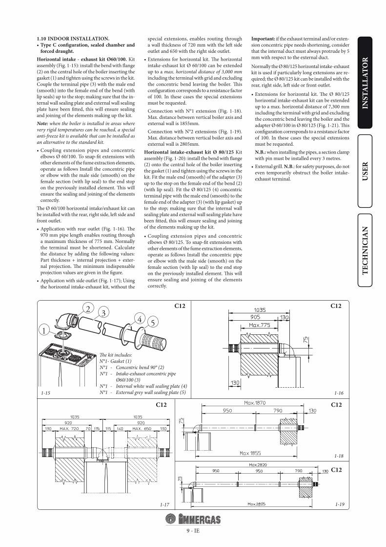
1.10 INDOOR INSTALLATION.• Type C configuration, sealed chamber and
forced draught.Horizontal intake - exhaust kit Ø60/100. Kit assembly (Fig. 1-15): install the bend with flange (2) on the central hole of the boiler inserting the gasket (1) and tighten using the screws in the kit. Couple the terminal pipe (3) with the male end (smooth) into the female end of the bend (with lip seals) up to the stop; making sure that the in-ternal wall sealing plate and external wall sealing plate have been fitted, this will ensure sealing and joining of the elements making up the kit.Note: when the boiler is installed in areas where very rigid temperatures can be reached, a special anti-freeze kit is available that can be installed as an alternative to the standard kit.• Coupling extension pipes and concentric
elbows Ø 60/100. To snap-fit extensions with other elements of the fume extraction elements, operate as follows Install the concentric pipe or elbow with the male side (smooth) on the female section (with lip seal) to the end stop on the previously installed element. This will ensure the sealing and joining of the elements correctly.
The Ø 60/100 horizontal intake/exhaust kit can be installed with the rear, right side, left side and front outlet.• Application with rear outlet (Fig. 1-16). The
970 mm pipe length enables routing through a maximum thickness of 775 mm. Normally the terminal must be shortened. Calculate the distance by adding the following values: Part thickness + internal projection + exter-nal projection. The minimum indispensable projection values are given in the figure.
• Application with side outlet (Fig. 1-17); Using the horizontal intake-exhaust kit, without the
special extensions, enables routing through a wall thickness of 720 mm with the left side outlet and 650 with the right side outlet.
• Extensions for horizontal kit. The horizontal intake-exhaust kit Ø 60/100 can be extended up to a max. horizontal distance of 3,000 mm including the terminal with grid and excluding the concentric bend leaving the boiler. This configuration corresponds to a resistance factor of 100. In these cases the special extensions must be requested.
Connection with N°1 extension (Fig. 1-18). Max. distance between vertical boiler axis and external wall is 1855mm.
Connection with N°2 extensions (Fig. 1-19). Max. distance between vertical boiler axis and external wall is 2805mm.
Horizontal intake-exhaust kit Ø 80/125 Kit assembly (Fig. 1-20): install the bend with flange (2) onto the central hole of the boiler inserting the gasket (1) and tighten using the screws in the kit. Fit the male end (smooth) of the adapter (3) up to the stop on the female end of the bend (2) (with lip seal). Fit the Ø 80/125 (4) concentric terminal pipe with the male end (smooth) to the female end of the adapter (3) (with lip gasket) up to the stop; making sure that the internal wall sealing plate and external wall sealing plate have been fitted, this will ensure sealing and joining of the elements making up the kit.
• Coupling extension pipes and concentric elbows Ø 80/125. To snap-fit extensions with other elements of the fume extraction elements, operate as follows Install the concentric pipe or elbow with the male side (smooth) on the female section (with lip seal) to the end stop on the previously installed element. This will ensure sealing and joining of the elements correctly.
Important: if the exhaust terminal and/or exten-sion concentric pipe needs shortening, consider that the internal duct must always protrude by 5 mm with respect to the external duct.
Normally the Ø 80/125 horizontal intake-exhaust kit is used if particularly long extensions are re-quired; the Ø 80/125 kit can be installed with the rear, right side, left side or front outlet.
• Extensions for horizontal kit. The Ø 80/125 horizontal intake-exhaust kit can be extended up to a max. horizontal distance of 7,300 mm including the terminal with grid and excluding the concentric bend leaving the boiler and the adapter Ø 60/100 in Ø 80/125 (Fig. 1-21). This configuration corresponds to a resistance factor of 100. In these cases the special extensions must be requested.
N.B.: when installing the pipes, a section clamp with pin must be installed every 3 metres.
• External grill. N.B.: for safety purposes, do not even temporarily obstruct the boiler intake-exhaust terminal.
The kit includes:N°1 - Gasket (1) N°1 - Concentric bend 90° (2) N°1 - Intake-exhaust concentric pipe
Ø60/100 (3) N°1 - Internal white wall sealing plate (4) N°1 - External grey wall sealing plate (5)
C32
1-241-23
C32
C12
1-20
C12
1-21
1
32
5 64
1
2
3
4
6
57
8
10 - IE
INST
ALL
ATO
RU
SER
TECH
NIC
IAN
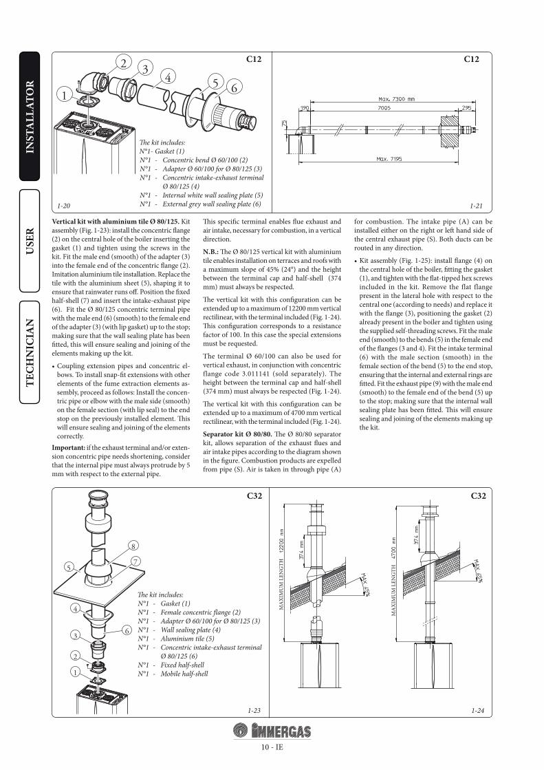
Vertical kit with aluminium tile Ø 80/125. Kit assembly (Fig. 1-23): install the concentric flange (2) on the central hole of the boiler inserting the gasket (1) and tighten using the screws in the kit. Fit the male end (smooth) of the adapter (3) into the female end of the concentric flange (2). Imitation aluminium tile installation. Replace the tile with the aluminium sheet (5), shaping it to ensure that rainwater runs off. Position the fixed half-shell (7) and insert the intake-exhaust pipe (6). Fit the Ø 80/125 concentric terminal pipe with the male end (6) (smooth) to the female end of the adapter (3) (with lip gasket) up to the stop; making sure that the wall sealing plate has been fitted, this will ensure sealing and joining of the elements making up the kit.
• Coupling extension pipes and concentric el-bows. To install snap-fit extensions with other elements of the fume extraction elements as-sembly, proceed as follows: Install the concen-tric pipe or elbow with the male side (smooth) on the female section (with lip seal) to the end stop on the previously installed element. This will ensure sealing and joining of the elements correctly.
Important: if the exhaust terminal and/or exten-sion concentric pipe needs shortening, consider that the internal pipe must always protrude by 5 mm with respect to the external pipe.
This specific terminal enables flue exhaust and air intake, necessary for combustion, in a vertical direction.
N.B.: The Ø 80/125 vertical kit with aluminium tile enables installation on terraces and roofs with a maximum slope of 45% (24°) and the height between the terminal cap and half-shell (374 mm) must always be respected.
The vertical kit with this configuration can be extended up to a maximum of 12200 mm vertical rectilinear, with the terminal included (Fig. 1-24). This configuration corresponds to a resistance factor of 100. In this case the special extensions must be requested.
The terminal Ø 60/100 can also be used for vertical exhaust, in conjunction with concentric flange code 3.011141 (sold separately). The height between the terminal cap and half-shell (374 mm) must always be respected (Fig. 1-24).
The vertical kit with this configuration can be extended up to a maximum of 4700 mm vertical rectilinear, with the terminal included (Fig. 1-24).
Separator kit Ø 80/80. The Ø 80/80 separator kit, allows separation of the exhaust flues and air intake pipes according to the diagram shown in the figure. Combustion products are expelled from pipe (S). Air is taken in through pipe (A)
for combustion. The intake pipe (A) can be installed either on the right or left hand side of the central exhaust pipe (S). Both ducts can be routed in any direction.
• Kit assembly (Fig. 1-25): install flange (4) on the central hole of the boiler, fitting the gasket (1), and tighten with the flat-tipped hex screws included in the kit. Remove the flat flange present in the lateral hole with respect to the central one (according to needs) and replace it with the flange (3), positioning the gasket (2) already present in the boiler and tighten using the supplied self-threading screws. Fit the male end (smooth) to the bends (5) in the female end of the flanges (3 and 4). Fit the intake terminal (6) with the male section (smooth) in the female section of the bend (5) to the end stop, ensuring that the internal and external rings are fitted. Fit the exhaust pipe (9) with the male end (smooth) to the female end of the bend (5) up to the stop; making sure that the internal wall sealing plate has been fitted. This will ensure sealing and joining of the elements making up the kit.
The kit includes:N°1 - Gasket (1) N°1 - Concentric bend Ø 60/100 (2) N°1 - Adapter Ø 60/100 for Ø 80/125 (3) N°1 - Concentric intake-exhaust terminal
Ø 80/125 (4) N°1 - Internal white wall sealing plate (5) N°1 - External grey wall sealing plate (6)
The kit includes: N°1 - Gasket (1) N°1 - Female concentric flange (2) N°1 - Adapter Ø 60/100 for Ø 80/125 (3) N°1 - Wall sealing plate (4) N°1 - Aluminium tile (5) N°1 - Concentric intake-exhaust terminal
Ø 80/125 (6) N°1 - Fixed half-shell N°1 - Mobile half-shell
MA
XIM
UM
LEN
GTH
MA
XIM
UM
LEN
GTH

C82
1-25
C42
C521-26
1-28
C82
1-27
4
65
1
3
2
785
9
7A
S
11 - IE
INST
ALL
ATO
RU
SER
TECH
NIC
IAN
• Coupling of extension pipes and elbows. To install snap-fit extensions with other elements of the fume extraction elements assembly, pro-ceed as follows: Install the pipe or elbow with the male side (smooth) on the female section (with lip seal) to the end stop on the previously installed element. This will ensure sealing and joining of the elements correctly.
• Figure 1-27 shows the configuration with vertical exhaust and horizontal intake.
• Installation clearances. Figure 1-26 gives the min. installation space dimensions of the Ø 80/80 separator terminal kit in limited condi-tions.
• Extensions for the separator kit Ø 80/80. The max. vertical straight length (without bends) that can be used for Ø 80 intake and exhaust
pipes is 41 metres of which 40 intake and 1 exhaust. The total length corresponds to a resistance factor of 100. The total usable length obtained by adding the length of the intake and exhaust pipes Ø 80 must not exceed the values stated in the following table. If mixed accessori-es or components are used (e.g. changing from a separator Ø 80/80 to a concentric pipe), the maximum extension can be calculated by using a resistance factor for each component or the equivalent length. The sum of these resistance factors must not exceed 100.
• Temperature loss in fume ducts. To prevent problems of fume condensate in the exhaust pipe Ø 80, due to fume cooling through the wall, the length of the pipe must be limited to just 5 m. Fig. 1-28). If longer distances must
be covered, use Ø 80 pipes with insulation (see insulated separator kit Ø 80/80 chapter).
N.B.: when installing the Ø 80 ducts, a section clamp with pin must be installed every 3 metres.
* The air intake pipe can be increased to 2.5 metres if the exhaust bend is eliminated, 2 metres if the air intake bend is eliminated, and 4.5 metres eliminating both bends.
The kit includes: N°1 - Exhaust gasket (1) N°1 - Female intake flange (3) N°1 - Flange gasket (2) N°1 - Female exhaust flange (4) N°2 - 90° bend Ø 80 (5) N°1 - Intake terminal Ø 80 (6) N°2 - Internal white wall sealing plates (7) N°1 - External grey wall sealing ring (8) N°1 - Exhaust pipe Ø 80 (9)
Maximum usable length (including intake terminal with grill and two 90° bends)
NON INSULATED PIPE INSULATED PIPEExhaust (m) Intake (m) Exhaust (m) Intake (m)
1 36,0* 6 29,5*2 34,5* 7 28,0*3 33,0* 8 26,5*4 32,0* 9 25,5*5 30,5* 10 24,0*
* The air intake pipe can be increased to 2.5 metres if the exhaust bend is eliminated, 2 metres if the air intake bend is eliminated, and 4.5 metres eliminating both bends.
11 22,5*
12 21,5*
Important: the boiler was designed to evacuate combustion product up to a maximum extension of 27 linear m to the exhaust, with 1 m plus 90° bend at intake. If installation requires an exten-sion of the flue fittings up to the exhaust that
exceeds the 12 m recommended, it is necessary to properly consider the possibility that conden-sation may form inside the duct and therefore Immergas “Serie Blu” insulated flue fittings, or other flue fittings with similar characteristics,
should be used.

1-30
1-311-29
5
4
1
3
2
5 6 7 88
10 11 9
SA
C82
C82C82
12 - IE
INST
ALL
ATO
RU
SER
TECH
NIC
IAN
Insulated separator kit Ø 80/80. Kit assembly (Fig. 1-29): install flange (4) on the central hole of the boiler, fitting gasket (1) and tighten with the flat-tipped hex screws included in the kit. Remove the flat flange present in the lateral hole with respect to the central one (according to ne-eds) and replace it with the flange (3), positioning the gasket (2) already present in the boiler and tighten using the supplied self-threading screws. Insert and slide cap (6) onto bend (5) from the male side (smooth), and join bends (5) with the male side (smooth) in the female side of flange (3). Fit bend (11) with the male side (smooth) into the female side of flange (4). Fit the male end (smooth) of the intake terminal (7) up to the stop on the female end of the bend (5), making sure you have already inserted the wall sealing plates (8 and 9) that ensure correct installation between pipe and wall, then fix the closing cap (6) on the terminal (7). Join the exhaust pipe (10) with the male side (smooth) in the female side of the bend (11) to the end stop, ensuring that the wall sealing plate (8) is already inserted for correct installation between the pipe and flue.
• Coupling extension pipes and elbows. To snap-fit extensions with other elements of the fume extraction elements, operate as fol-lows: Install the concentric pipe or elbow with the male side (smooth) on the female section (with lip seal) to the end stop on the previously installed element. This will ensure sealing and joining of the elements correctly.
• Insulation of separator terminal kit. In case of problems of fume condensate in the exhaust pi-pes or on the outside of intake pipes, Immergas supplies insulated intake and exhaust pipes on request. Insulation may be necessary on the exhaust pipe due to excessive temperature loss of fumes during conveyance. Insulation may be necessary on the intake pipe as the air entering (if very cold) may cause the outside of the pipe to fall below the dew point of the environmen-
tal air. The figures (Fig. 1-29 and 1-30) illustrate different applications of insulated pipes.
Insulated pipes are formed of a Ø 80 internal concentric pipe and a Ø 125 external pipe with static air space. It is not technically possible to start with both Ø 80 elbows insulated, as clearances will not allow it. However starting with an insulated elbow is possible by choosing either the intake or exhaust pipe. When star-ting with an insulated intake bend, it must be inserted onto its flange up to the stop on the fume exhaust flange, which will ensure that the two intake and exhaust outlets are at the same height.
• Temperature loss in insulated fume ducting. To prevent problems of fume condensate in the exhaust pipe Ø 80, due to fume cooling through the wall, the length of the pipe must be limited to 12 m. The figure (Fig. 1-31) illu-strates a typical insulation application in which the intake pipe is short and the exhaust pipe is very long (over 5 m). The entire intake pipe is insulated to prevent moist air in the place where the boiler is installed, in contact with the pipe cooled by air entering from the outside. The entire exhaust pipe, except the elbow leaving the splitter is insulated to reduce heat loss from the pipe, thus preventing the formation of fume condensate.
N.B.: When installing the ducts, a section clamp with pin must be installed every 2 me-tres.
• Configuration type B, open chamber and forced draught.
When using type B installation configuration indoors, it is compulsory to install the relative up-per cover kit along with the fumes discharge kit. The air intake comes directly from the area where the boiler is installed and from the flue exhaust in each single flue or directly from outdoors.The boiler in this configuration, following the
assembly instructions on pages 8 and 9, is clas-sified as type B.With this configuration:- air intake takes place directly from the environ-
ment in which the boiler is installed and only functions in permanently ventilated rooms;
- the flue exhaust must be connected to its own individual flue or channelled directly into the external atmosphere.
- Type B open chamber boilers must not be installed in places where commercial, artisan or industrial activities take place, which use products that may develop volatile vapours or substances (e.g. acid vapours, glues, paints, solvents, combustibles, etc.), as well as dusts (e.g. dust deriving from the working of wood, coal fines, cement, etc.), which may be dama-ging for the components of the appliance and jeopardise functioning.
When using type B installation configuration indoors, it is compulsory to install the relative up-per cover kit along with the fumes discharge kit.The technical regulations in force must be respected.
The kit includes: N°1 - Exhaust gasket (1) N°1 - Flange seal (2) N°1 - Female intake flange (3) N°1 - Female exhaust flange (4) N°1 - Bend 90° Ø 80 (5) N°1 - Pipe closure cap (6) N°1 - Intake terminal Ø 80 insulated (7) N°2 - Internal white wall sealing plates (8) N°1 - External grey wall sealing plate (9) N°1 - Discharge pipe Ø 80 insulated (10) N°1 - Concentric bend 90° Ø 80/125 (11)

1-32
A
C
B
D
13 - IE
INST
ALL
ATO
RU
SER
TECH
NIC
IAN
1.11 FUME EXHAUST TO FLUE/CHIMNEY.
Flue exhaust does not necessarily have to be con-nected to a branched type traditional flue. Flue exhaust can be connected to a special LAS type multiple flue. Multiple and combined flues must be specially designed according to the calculation method and requirements of the standards, by professionally qualified technical personnel. Chimney or flue sections for connection of the exhaust pipe must comply with requisites of technical standards in force.
1.12 DUCTING OF EXISTING FLUES.With a specific “ducting system” it is possible to reuse existing flues, chimneys and technical openings to discharge the boiler fumes. Ducting requires the use of ducts declared to be suitable for the purpose by the manufacturer. Follow the installation and user instructions provided by the manufacturer and the requirements of standards.
1.13 FLUES, CHIMNEYS AND CHIMNEY CAPS.
The flues, chimneys and chimney caps for the evacuation of combustion products must be in compliance with applicable standards.
Positioning the draft terminals. Draft termi-nals must:- be installed on external perimeter walls of the
building;- be positioned according to the minimum di-
stances specified in current technical standards.Fume exhaust of forced draught appliances in closed open-top environments. In spaces clo-sed on all sides with open tops (ventilation pits, courtyards etc.), direct fume exhaust is allowed for natural or forced draught gas appliances with a heating power range from 4 to 35 kW, provi-ded the conditions as per the current technical standards are respected.
1.14 SYSTEM FILLING.Once the boiler is connected, proceed with system filling via the filling valve (Fig. 2-2). Filling is performed at low speed to en-sure release of air bubbles in the wa-ter via the boiler and heating system vents. The boiler has a built-in automatic ven-ting valve on the circulator. Open the ra-
diator air vent valves. Close radiator vent valves only when water escapes from them. Close the filling valve when the boiler manometer indicates approx. 1.2 bar.
N.B.: during these operations turn on the circula-tion pump at intervals, by means of the stand-by/summer winter switch positioned on the control panel. Vent the circulation pump by loosening the front cap and keeping the motor running.Tighten the cap afterwards.
1.15 GAS SYSTEM START-UP.To start up the system proceed as follows:- open windows and doors;- avoid presence of sparks or naked flames;- bleed all air from pipelines;- check that the internal system is properly sealed
according to specifications.
1.16 BOILER START UP (IGNITION).For issue of the Declaration of Conformity pro-vided for by Italian Law, the following must be performed for boiler start-up:- check that the internal system is properly sealed
according to specifications;- ensure that the type of gas used corresponds to
boiler settings;- switch the boiler on and ensure correct ignition;- make sure that the gas flow rate and relevant
pressure values comply with those given in the manual (parag. 3.17);
- ensure that the safety device is engaged in the event of gas supply failure and check activation time;
- check activation of the main switch located upstream from the boiler;
- check that the concentric intake-exhaust ter-minal (if fitted) is not blocked.
The boiler must not be started up in the event of failure to comply with any of the above.
N.B.: the initial check of the boiler must be perfor-med by a qualified technician. The conventional warranty of the boiler comes into effect from the date of the check itself. The initial check certificate and warranty are issued to the user.
1.17 CIRCULATION PUMP.Eolo Star 24 3 E Range boilers are supplied with a built-in circulation pump with 3-position electric speed control. The boiler does not operate cor-rectly with the circulation pump on first speed. To ensure optimal boiler operation, in the case of new systems (single pipe and module) it is recommended to use the circulation pump at maximum speed. The circulation pump is already fitted with a capacitor.
Pump release. If, after a prolonged period of inactivity, the circulation pump is blocked, unscrew the front cap and turn the motor shaft using a screwdriver. Take great care during this operation to avoid damage to the motor.
By-pass regulation (part. 24 Fig. 1-33). If neces-sary, the by-pass can be regulated according to plant requirements from a minimum (by-pass excluded) to a maximum (by-pass inserted) represented by the following graphics (Fig. 1-32). Make the regulation using a flat head screwdriver, turn clockwise and insert the by-pass, anti-clockwise it is excluded.
Hea
d (m
H2O
)
Flow rate (l/h)
Hea
d (k
Pa)
Total head available to the plant.
A = Head available to the system at maximum speed with by-pass excluded.
B = Head available to the system at maximum speed with by-pass inserted.
C = Head available to the system at second speed with by-pass excluded.
D = Head available to the system at second speed with by-pass inserted.

14 - IE
INST
ALL
ATO
RU
SER
TECH
NIC
IAN
1.19 BOILER COMPONENTS.
Key: 1 - Sample points (air A) - (fumes F) 2 - Sealed chamber 3 - Fan 4 - Combustion chamber 5 - Domestic hot water flow switch 6 - Gas valve 7 - Domestic hot water probe 8 - System filling cock 9 - Positive signal pressure point 10 - Negative signal pressure point 11 - Fumes pressure switch
12 - Safety thermostat 13 - Fumes hood 14 - Delivery probe 15 - Rapid heat exchanger 16 - Ignition and detection electrodes 17 - System expansion vessel 18 - Burner 19 - System pressure switch 20 - Air vent valve 21 - Boiler circulating pump 22 - Manifold 23 - System drain cock 24 - By-pass 25 - 3 bar safety valve
N.B.: connection group (optional)
1.18 KITS AVAILABLE ON REQUEST.• System shut off valves kit. The boiler is desig-
ned for installation of system shut off valves to be placed on delivery and return pipes of the connection assembly. This kit is particularly useful for maintenance as it allows the boiler to be drained separately without having to empty the entire system.
• a) Polyphosphate dispenser kit for wall instal-lation.
• b) Polyphosphate dispenser kit for installation with recess frame.
The polyphosphate dispenser reduces the for-mation of lime-scale and preserves the original heat exchange and domestic hot production water conditions. The boiler is prepared for application of the polyphosphate dispenser kit.
• Covering kit. For outdoor installations, in partially protected areas and with direct air intake, the top protection cover must be fitted for a correct functioning of the boiler and to protect it from storms (Fig. 1-8). For indoor installations, type B configuration, a suitable top protection cover coupled with the flue exhaust kit must be fitted.
• Anti freeze kit with resistance (on request). If the boiler is installed in a place where the tem-perature falls below -5°C and in the event there is no gas, the appliance can freeze. To prevent freezing of the domestic hot water system, an anti freeze kit with an electrical resistance can be fitted from the relative cable and from a control thermostat.
• Installation kit with recess frame. Using a suitable recess frame, it is possible to fit the boiler inside the wall, configuration type C, or with direct outdoor air intake, thanks to the ventilated recess frame.
• a)- Attachment kit for wall installation.• b)- Attachment kit for recess boiler. The kit includes pipes, fittings and cocks (inclu-
ding gas cock) for the connection of the boiler to the system and 4 spacers to be used under the side plugs of the sealed chamber (the plugs are recess type).
N.B.: for recess fitting, using the same kit (b), it is possible to carry out front installation or back installation exiting the recess frame.
The above-mentioned kits are supplied complete with instructions for assembly and use.

2-1
15 - IE
INST
ALL
ATO
RU
SER
TECH
NIC
IAN
2 INSTRUCTIONS FOR USE AND MAINTENANCE.
2.1 CLEANING AND MAINTENANCE.Important: the heating plants must undergo periodical maintenance (regarding this, see in the section dedicated to the technician, relative to “yearly control and maintenance of the ap-pliance”) and regular checks of energy efficiency in compliance with national, regional or local provisions in force. This ensures that the optimal safety, performance and operation characteristics of the boiler remain unchanged over time.We recommend stipulating a yearly cleaning and maintenance contract with your zone technician.
2.2 GENERAL WARNINGS.Never expose the suspended boiler to direct vapours from a cooking surface.Use of the boiler by unskilled persons or children is strictly prohibited.Do not touch the fumes exhaust terminal (if present) due to the high temperature it reaches;For safety purposes, check that the concentric air intake/flue exhaust terminal (if fitted), is not blocked.If temporary shutdown of the boiler is required, proceed as follows:a) drain the heating system if anti-freeze is not
used;b) shut-off all electrical, water and gas supplies.
In the case of work or maintenance to structu-res located in the vicinity of ducting or devi-ces for flue extraction and relative accessories, switch off the appliance and on completion of operations ensure that a qualified technician checks efficiency of the ducting or other devices. Never clean the appliance or connec-ted parts with easily flammable substances. Never leave containers or flammable substances in the same environment as the appliance.
• Important: the use of components involving use of electrical power requires some funda-mental rules to be observed:
- do not touch the appliance with wet or moist parts of the body; do not touch when barefoot;
- never pull electrical cables or leave the ap-pliance exposed to atmospheric agents (rain, sunlight, etc.);
- the appliance power cable must not be replaced by the user;
- in the event of damage to the cable, switch off the appliance and contact exclusively qualified staff for replacement;
- if the appliance is not to be used for a certain period, disconnect the main power switch.
2.3 CONTROL PANEL.
Key: 1 - Reset key 2 - Stand-by key/ summer / winter 3 - Key (+) to increase the domestic hot water
temperature 4 - Key (-) to reduce the domestic hot water
temperature
5 - Key (+) to increase the system water temperature
6 - Key (-) to reduce the system water temperature
7 - Boiler manometer 8 - Domestic hot water function 9 - Temperature and error code display
10 - Unit of measurement 11 - Heating mode 12 - Winter 13 - Summer 14 - Output efficiency 15 - Flame presence

16 - IE
INST
ALL
ATO
RU
SER
TECH
NIC
IAN
Ignition of the boiler (Fig. 2-1). Before ignition, make sure the heating system is filled with water and that the manometer (7) indicates a pressure of 1 ÷ 1.2 bar.- Open the gas cock upstream from the boiler.- Press key (2) and select the summer position
or winter ( ) position of the boiler ( ).
When in summer position( ) the domestic hot water temperature is regulated by keys (3-4).
When in winter position ( ) the system water temperature is regulated by keys (5-6) whilst the regulation of the domestic hot water temperature is regulated using keys (3-4), pressing (+) to increase and (-) to reduce.
From this moment the boiler functions auto-matically. With no demand for heat (heating or domestic hot water production) the boiler goes to “standby” function, equivalent to the boiler being powered without presence of flame. Each time the boiler ignites, the relative flame present symbol is displayed (15).
2.4 FAULT AND ANOMALY SIGNALS.The boiler signals out anomalies by flashing on the display and relative error codes, listed on the table, are displayed.
Anomaly signalledcode
displayed(flashing)
Ignition block 01
Safety thermostat block (over-temperature), flame control anomaly
02
Electro-mechanical contacts 04
Delivery probe anomaly 05
Domestic hot water probe anomaly 06
Insufficient system pressure 10
Fumes pressure switch failure 11
Parasite flame 20
Insufficient circulation 27
Extruder presence 28
Communication loss with CRD 31
Ignition block. The boiler ignites automatically with each demand for room heating or hot water production. If this does not occur within 10 seconds, the boiler goes into ignition block (code 01). To eliminate “ignition block” the Reset button (1) must be pressed. On commissioning or after extended inactivity it may be necessary to eliminate the “ignition block”. If this pheno-menon occurs frequently, contact a qualified technician for assistance (e.g. Immergas After-Sales Technical Assistance Service).
Over temperature thermostat block. During normal functioning, if a fault causes excessive overheating internally, the boiler goes into over temperature block (code 02). After allowing to cool, eliminate the “overtemperature block” by pressing the Reset key (1). If this phenomenon occurs frequently, contact a qualified technician for assistance (e.g. Immergas After-Sales Tech-nical Assistance Service).
Electro-mechanical contacts This occurs when the safety thermostat, the fume pressure switch or the system pressure switch do not work properly (code 04). Try resetting the boiler. If the anomaly continues contact a qualified technician for assistance (e.g. Immergas After-Sales Technical Assistance Service).
Delivery probe anomaly If the board detects an anomaly on the delivery probe (code 05), the boi-ler will not start; contact a qualified technician for assistance (e.g. Immergas After-Sales Technical Assistance Service).
Domestic hot water probe anomaly. If the board detects an anomaly on the delivery probe (code 06), the boiler will not start; contact a qualified technician for assistance (e.g. Immergas After-Sales Technical Assistance Service).
Insufficient system pressure. Water pressure inside the heating system (code 10), sufficient to guarantee the correct functioning of the boiler, is not detected. Check that the system pressure is between 1÷1.2 bar.
Fumes pressure switch failure. This occurs if the intake or exhaust pipes are blocked or in case of a fan fault (code 11). If normal conditions are restored the boiler restarts without having to be reset. If this anomaly persists, contact a qualified technician for assistance (e.g. Immergas After-Sales Technical Assistance Service.)
Parasite flame. This occurs in case of a leak on the detection circuit or anomaly in the flame control unit. (code 20), try to reset the boiler. If the anomaly continues contact a qualified technician (e.g. Immergas After-Sales Technical Assistance Service).
Insufficient water circulation. This occurs if there is overheating in the boiler due to insuf-ficient water circulating in the primary circuit (code 27); the causes can be:
- low circulation; check that no shut off devices are closed on the heating circuit and that the system is free of air (deaerated);
- circulating pump blocked; free the circulating pump.
If this phenomenon occurs frequently, contact a qualified technician for assistance (e.g. Immergas After-Sales Technical Service).
Domestic hot water extruder circuit. If during the heating phase, a rise in domestic hot water temperature occurs, an anomaly is signalled (code 28) and heating temperature is reduced to limit the formation of lime scale in the heat exchanger. Check that all domestic hot water system cocks are closed and are not drawing and check also that there are no leaks in the system. Once good conditions are restored in the domestic hot water system, the boiler returns to normal functioning.If this anomaly persists, contact a qualified tech-nician for assistance (e.g. Immergas After-Sales Technical Assistance Service).
Loss of Digital Remote Control communica-tion. This occurs 1 minute after communication loss between the boiler and the CRD (code 31). To reset the error code, remove and re-apply power to the boiler. If this phenomenon occurs frequently, contact a qualified technician for assistance (e.g. Immergas After-Sales Technical Assistance Service).
Boiler shutdown Press key (2 Fig. 2-1) () until the following symbol appears
( ).
N.B.: in these conditions the boiler is considered still powered.
Disconnect the external omnipolar boiler switch and close the gas cock upstream of the appliance. Never leave the boiler switched on if left unused for prolonged periods.
2.5 RESTORE HEATING SYSTEM PRESSURE.
Periodically check the system water pressure. The boiler pressure gauge should read a pressure between 1 and 1.2 bar.If the pressure is below 1 bar (with the circuit cool) restore normal pressure via the cock located in the lower part of the boiler (Fig. 2-2).
N.B.: close the cock after the operation.If pressure values reach around 3 bar t h e s a f e t y v a l v e m a y b e a c t i v a t e d . In this case contact a professional technician for assistance.
In the event of frequent pressure drops, contact qualified staff for assistance to eliminate the possible system leakage.
2.6 DRAINING THE SYSTEM.To drain the boiler, use the special drain cock (Fig. 1-33).Before draining, ensure that the filling cock is closed.
2.7 ANTI-FREEZE PROTECTION.The boiler is supplied with an antifreeze function as per standard that activates the function of the pump and the burner when the internal system water temperature in the boiler falls below 4 °C (protection range to a minimum temperature of -5°C) and stops when it exceeds 42°C. The antifreeze function is guaranteed if the boiler is fully operative, is not in “block” status and is electrically powered. To avoid keeping the system switched on in case of a prolonged absence, the system must be drained completely or antifreeze substances must be added to the heating system water. In both cases the boiler domestic hot water circuit must be drained. In systems that are drai-ned frequently, filling must be carried out with suitably treated water to eliminate hardness that can cause lime-scale.All information relative to the anti-freeze protec-tion is stated in Par. 1.4. In order to guarantee the integrity of the appliance and the domestic hot water heating system in zones where the tempera-ture falls below zero, we recommend the heating system is protected using anti-freeze liquid and installation of the Immergas Anti-freeze Kit in the boiler (Par. 1.4). In the case of prolonged inactivity (second case), we also recommend that:- disconnect the electric power supply;- drain completely the boiler domestic hot water
circuit using the exhaust valves provided (Fig. 1-33) and the internal domestic hot water system.
2-2
17 - IE
INST
ALL
ATO
RU
SER
TECH
NIC
IAN
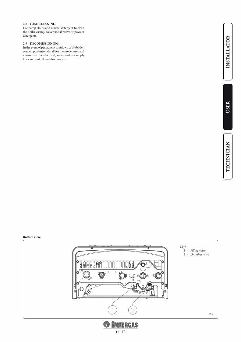
2.8 CASE CLEANING.Use damp cloths and neutral detergent to clean the boiler casing. Never use abrasive or powder detergents.
2.9 DECOMISSIONING.In the event of permanent shutdown of the boiler, contact professional staff for the procedures and ensure that the electrical, water and gas supply lines are shut off and disconnected.
Key: 1 - Filling valve 2 - Draining valve
Bottom view.

3-1
18 - IE
INST
ALL
ATO
RU
SER
TECH
NIC
IAN
3 BOILER START-UP. (INITIAL CHECK)
To commission the boiler:- ensure that the declaration of conformity of
installation is supplied with the appliance;- ensure that the type of gas used corresponds to
boiler settings;- check connection to a 230V-50Hz power
mains, correct L-N polarity and the earthing connection;
- make sure the heating system is filled with wa-ter and that the manometer indicates a pressure of 1÷1.2 bar;
- make sure the air valve cap is open and that the system is well deaerated;
- switch the boiler on and ensure correct ignition;
- make sure the gas maximum, medium and minimum flow rate and pressure values correspond to those given in the handbook (Paragraph 3.17);
- check activation of the safety device in the event of no gas, as well as the relative activation time;
- check activation of the main switch located upstream from the boiler;
- check that the intake and/or exhaust terminals are not blocked;
- check activation of the “no air” safety pressure switch;
- ensure activation of all adjustment devices;- seal the gas flow rate regulation devices (if
settings are modified);- ensure production of domestic hot water;- ensure sealing efficiency of water circuits;
- check ventilation and/or aeration of the instal-lation room where provided.
If any checks/inspection relative to safety give negative results, do not start the system.
3.1 HYDRAULIC LAYOUT.
Key: 1 - Domestic hot water probe 2 - Domestic hot water flow switch 3 - Gas valve 4 - Flow limiter 5 - System draining valve 6 - Burner 7 - Rapid heat exchanger 8 - Fan 9 - Sealed chamber 10 - Fumes pressure switch 11 - Fumes hood 12 - System expansion vessel 13 - Delivery probe 14 - Safety thermostat 15 - Air vent valve 16 - Boiler circulating pump 17 - System pressure switch; 18 - By-pass 19 - 3 bar safety valve 20 - System filling valve
G - Gas supply AC - Domestic hot water outlet AF - Domestic hot water inlet R - System return M - System delivery
3-210
6
1
3
2
7654
5 6 5
5 6
10
9988 810
10
8 911
11
9
19 - IE
INST
ALL
ATO
RU
SER
TECH
NIC
IANKey:
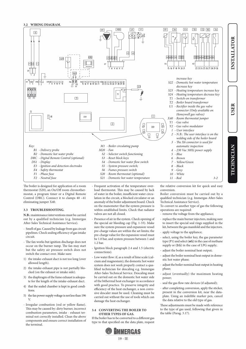
B1 - Delivery probe B2 - Domestic hot water probe DRC - Digital Remote Control (optional) DS1 - Display E3 - Ignition and detection electrodes E4 - Safety thermostat F1 - Phase fuse F2 - Neutral fuse
3.2 WIRING DIAGRAM.
The boiler is designed for application of a room thermostat (S20), an On/Off room chronother-mostat, a program timer or a Digital Remote Control (DRC). Connect it to clamps 40 –41 eliminating jumper X40.
3.3 TROUBLESHOOTING.N.B.: maintenance interventions must be carried out by a qualified technician (e.g. Immergas After-Sales Technical Assistance Service).
- Smell of gas. Caused by leakage from gas circuit pipelines. Check sealing efficiency of gas intake circuit.
- The fan works but ignition discharge does not occur on the burner ramp. The fan may start but the safety air pressure switch does not switch the contact over. Make sure:
1) the intake-exhaust duct is not too long (over allowed length).
2) the intake-exhaust pipe is not partially blo-cked (on the exhaust or intake side).
3) the diaphragm of the fume exhaust is adequa-te for the length of the intake-exhaust duct.
4) that the sealed chamber is kept in good condi-tions.
5) the fan power supply voltage is not less than 196 V.
- Irregular combustion (red or yellow flame). This may be caused by: dirty burner, incorrect combustion parameters, intake - exhaust ter-minal not correctly installed. Clean the above components and ensure correct installation of the terminal.
- Frequent activation of the temperature over-load thermostat. This may be caused by lack of water in the boiler, insufficient water circu-lation in the circuit, a blocked circulator or an anomaly of the boiler adjustment board. Check on the manometer that the system pressure is within established limits. Check that radiator valves are not all closed.
- Presence of air in the system. Check opening of the special air bleeding cap (Fig. 1-33). Make sure the system pressure and expansion vessel pre-charge values are within the set limits; the pre-charge value for the expansion vessel must be 1.0 bar, and system pressure between 1 and 1.2 bar.
- Ignition block paragraph 2.4 and 1.5 (electric connections).
- Low water flow: if, as a result of lime scale (cal-cium and magnesium), the domestic hot water system does not work properly contact a qua-lified technician for descaling e.g. Immergas After-Sales Technical Service. Descaling must be carried out on the domestic hot water side of the bithermal heat exchanger in accordance with good practice. To preserve integrity and efficiency of the heat exchanger, a non corro-sive descaler must be used. Cleaning must be carried out without the use of tools which can damage the heat exchanger.
3.4 CONVERTING THE BOILER TO OTHER TYPES OF GAS.
If the boiler has to be converted to a different gas type to that specified on the data plate, request
the relative conversion kit for quick and easy conversion. Boiler conversion must be carried out by a qualified technician (e.g. Immergas After-Sales Technical Assistance Service).To convert to another type of gas the following operations are required:- remove the voltage from the appliance;- replace the main burner injectors, making sure
to insert the special seal rings supplied in the kit, between the gas manifold and the injectors.
- apply voltage to the appliance;- select, using the boiler key, the gas parameter
type (P1) and select (nG) in the case of methane supply or (LG) in the case of LPG supply;
- adjust the boiler nominal heat output;- adjust the boiler nominal heat output in dome-
stic hot water phase;- adjust the boiler nominal heat output in heating
phase;- adjust (eventually) the maximum heating
power;- seal the gas flow rate devices (if adjusted);- after completing conversion, apply the sticker,
present in the conversion kit, near the data-plate. Using an indelible marker pen, cancel the data relative to the old type of gas.
These adjustments must be made with reference to the type of gas used, following that given in the table (Parag. 3.17).
M1 - Boiler circulating pump M20 - Fan S2 - Selector switch functioning S3 - Reset block keys S4 - Domestic hot water flow switch S5 - System pressure switch; S6 - Fumes pressure switch S20 - Room thermostat (optional) S21 - Domestic hot water temperature
increase key S22 - Domestic hot water temperature
decrease key S23 - Heating temperature increase key S24 - Heating temperature decrease key T1 - Switch-on transformer T2 - Boiler board transformer U1 - Rectifier inside the gas valve
connector (Only available on Honeywell gas valves)
X40 - Room thermostat jumper Y1 - Gas valve Y2 - Gas valve modulator 1 - User interface 2 - N.B.: The user interface is on the
welding side of the boiler board 3 - The X6 connector is used for
automatic inspection 4 - 230 Vac 50Hz power supply 5 - Blue 6 - Brown 7 - Yellow/Green 8 - Black 9 - Grey 10 - White 11 - Red

3-3
20 - IE
INST
ALL
ATO
RU
SER
TECH
NIC
IAN
3.5 CHECKS FOLLOWING CONVERSION TO ANOTHER TYPE OF GAS.
After making sure that conversion was carried out with a nozzle of suitable diameter for the type of gas used and the settings are made at the correct pressure, check that:- there is no flame in the combustion chamber;- the burner flame is not too high or low and that
it is stable (does not detach from burner);- the pressure testers used for calibration are
perfectly closed and there are no leaks from the gas circuit.
N.B.: all boiler adjustment operations must be carried out by a qualified technician (e.g. Immergas After-Sales Technical Assistance). Burner adjustment must be carried out using a differential “U” or digital type pressure gauge located above the sealed chamber (part. 9 Fig. 1-33) and the gas valve pressure outlet (part. 4 Fig. 3-3), keeping to the pressure value given in the table (Par. 3.17) according to the type of gas for which the boiler is prepared.
3.6 POSSIBLE ADJUSTMENTS.• Adjustment of boiler nominal thermal heat
output.- Press the (+) key to adjust the domestic hot
water temperature (3 Fig. 2-1) up to the maxi-mum temperature function.
- Open the domestic hot water cock in order to prevent modulation intervention.
- Adjust the boiler nominal power on the brass nut (3 Fig. 3.3), keeping to the maximum pressure values stated in the tables (Par. 3.17) depending on the type of gas.
- By turning in a clockwise direction the heating potential increases and in an anti-clockwise direction it decreases.
• Adjust the boiler minimum heat input in the domestic hot water phase (Fig. 3-3).
N.B.: only proceed after having calibrated the nominal pressure.
To adjust the minimum thermal output in do-mestic hot water phase, turn the nut (2) located on the gas valve blocking the brass nut (3);
- disconnect the power supply to the modulating coil (just disconnect a fasten); By turning the screw in a clockwise direction, the pressure increases, in an anti-clockwise direction it de-creases. On completion of calibration, re-apply the power supply to the modulating coil. The
pressure, to which the boiler minimum power must be adjusted, must not be lower than that stated in the tables (Par. 3.17) depending on the type of gas.
N.B.: to adjust the gas valve, remove the plastic cap (6); after adjusting, refit the cap.
• Adjustment of the boiler minimum heat output in heating phase.
N.B.: only proceed after having calibrated the minimum domestic hot water pressure.
To adjust the minimum heat output during the heating phase, change parameter (5), increasing the value the pressure increases, reducing it the pressure drops.
- The pressure to which the boiler minimum heat output must be adjusted must not be lower than that stated in the tables (Parag. 3.17).
3.7 PROGRAMMING THE P.C.BThe Eolo Star 24 3 E boiler is prepared for possible programming of several functioning parameters. By modifying these parameters as described below, the boiler can be adapted according to specific needs.
To access the programming phase, proceed as follows:
- press keys (1) and (2) at the same time for approximately 15 seconds;
- Using keys (3) and (4), select the parameter to be changed indicated in the following table:
List of parame-
tersDescription
P0 Select solar panels
P1 Select gas type
P2 select special gas type G110
P3 Activate anti extruder function
P4 Activate domestic hot water post circulation
P5 Minimum heating power
P6 Maximum heating power
P7 Heating ignition timer
P8 Heating ramp timer
- adjust the corresponding value consulting the table using keys (5) and (6);
- confirm the set value pressing the reset key (1) for approximately 5 seconds; pressing keys (3) + and (4) - at the same time to adjust the domestic hot water temperature, the operation is cancelled.
N.B.: after a period of time, without touching any keys, the operation cancels automatically.
Select solar panels By selecting this function, the boiler is set to be used with solar panels. Setting parameter P0 at on “solar”, the switching off of the burner is connected to the adjustment of the domestic hot water temperature. In OFF mode, the burner is switched off at maximum value.
N.B.: together with a solar valve kit, set the parameter P0 at on “solar” mode (correlated).
Select solar panels
Range of values which can be set Parameter
on "solar" - oF (Standard settings) P0
Select gas type The setting of this function is used to adjust the boiler in order to function with LPG gas or Methane gas.
Select gas type
Range of values which can be set Parameter
LG (GPL) o nG (Metano) (Standard settings) P1
Town Gas G110 – Industrial gas. The setting of this function is used to adjust the boiler in order to function with gases from the first family.
Town Gas G110 - Industrial gas (first family gas)
Range of values which can be set Parameter
on - oF (Standard setting) P2
SIT 845 GAS valve
Key: 1 - Coil 2 - Minimum power adjustment nut 3 - Maximum power adjustment nut 4 - Gas valve outlet pressure point 5 - Gas valve inlet pressure point 6 - Protection hood
VK 4105 M GAS valve
21 - IE
INST
ALL
ATO
RU
SER
TECH
NIC
IAN
Anti-Extruder function. This function reduces the heating temperature to 57°C in the case that domestic hot water circulation is detected in the heating mode.
Activate anti-extruder function
Range of values which can be set Parameter
on (Standard setting) - oF P3
Domestic hot water post circulation function With the post circulation function active after domestic hot water flow, the pump remains on for 2.5 seconds in winter time and 1.5 seconds in summer time to reduce the formation of lime scale.
Activate domestic hot water post circula-tion
Range of values which can be set Parameter
on (Settaggio di serie) - oF P4
Heating power. The Eolo Star 24 3 E boiler is fit-ted with an electronic modulation which adapts the power of the boiler to effective heat requests of the home. Then the boiler works normally in a variable gas pressure field between the minimum heating power and the maximum heating power depending on the system’s heating load.
N.B.: The Eolo Star 24 3 E boiler is produced and calibrated in the heating phase to the nominal heat output. Approximately 10 minutes are nee-ded to reach the nominal heat output changeable using parameter (P6).
N.B.: the selection of the “Minimum heating power” and “Maximum heating power” parame-ters, in the presence of a heating request, allows switch-on of the boiler and power supply of the modulator with current equal to the value of the respective set value.
Minimum heating power
Range of values which can be set Parameter
from 0 % Imax. to 63 % Imax. P5
Maximum heating power
Range of values which can be set Parameter
from 0 % Imax. to 99 % Imax. (Standard setting) P6
Timer setting. The boiler has an electronic timing device that prevents the burner from igniting too often in the heating phase. The boiler is supplied as per standard with a timer adjusted at 3 minutes.
Heating ignitions timer
Range of values which can be set Parameter
from 1 to 101 = 30 seconds2 = 2 minutes3 = 3 minutes (Standard setting)
P7
Heating ramp timing. The boiler performs an ignition ramp of about 10 minutes to arrive from minimum power to nominal heating power.
Heating ramp timing
Range of values which can be set Parameter
from 1 to 101 = 30 seconds2 = 2 minutes10 = 10 minutes (Standard setting)
P8
3.8 AUTOMATIC SLOW IGNITION FUNCTION WITH TIMED RAMP DELIVERY.
In the ignition phase the P.C.B. carries out an increasing gas delivery ramp (with pressure va-lues that depend on the type of gas selected) with preset duration. This prevents every calibration or precision adjustment of the boiler ignition phase in any conditions of use.
3.9 “CHIMNEY SWEEP FUNCTION”.When activated, this function forces the boiler at max. output for 15 minutes.In this state all adjustments are excluded and only the temperature safety thermostat and the limit thermostat remain active. To activate the chimney sweep function, press the Reset key for at least 10 seconds with the boiler on stand-by. Its activation is indicated by the flashing symbols (8 and 11 Fig. 2-1). This function allows the techni-cian to check the combustion parameters. After the checks, deactivate the function switching the boiler off and then on again.
3.10 HEATING TIMER.The Eolo Star 24 3 E boiler has an electronic timing device that prevents the burner from igniting too often in the heating phase. The boiler is supplied as per standard with a timer adjusted at 3 minutes. To adjust the timer values, follow instructions for parameter settings by selecting parameter (P7) and set it with one of the values indicated on the relative table.
3.11 PUMP ANTI-BLOCK FUNCTION.In summer function mode ( ) the boiler has a function that starts the pump at least once every 24 hours for the duration of 30 seconds in order to reduce the risk of the pump becoming blocked due to prolonged inactivity.In winter function mode ( ) the boiler has a function that makes the pump start at least once every 3 hours for 30 seconds.
3.12 FUNZIONE ANTITRAFILA CIRCUITO SANITARIO.
This function reduces the heating temperature to 57°C if the domestic hot water circulation is detected in the heating mode. The function can be excluded using parameter (P3).
3.13 RADIATORS ANTI-FREEZE FUNCTION.
If the system return water is below 4°C, the boiler starts up until reaching 42°C.
3.14 P.C.B. PERIODICAL SELF-CHECK.During functioning in heating mode or with boiler in standby, the function activates every 18 hours after the last boiler check/power supply. In case of functioning in domestic hot water mode the self-check starts within 10 minutes after the end of the withdrawing in progress, for duration of approx. 10 seconds.
N.B.: during self-check, the boiler remains off, including signalling.

22 - IE
INST
ALL
ATO
RU
SER
TECH
NIC
IAN
3.15 CASING REMOVAL (Fig 3-4).
To facilitate boiler maintenance the casing can be completely removed as follows:- Remove frame (1) grasping the edges and pul-
ling towards oneself as indicated by the arrow.- Loosen the 2 front screws (2) and the 2 screw
fasteners (3) below on the casing (4).- Pull the casing (4) towards yourself and up
at the same time to detach it from the upper hooks.
3.16 YEARLY APPLIANCE CHECK AND MAINTENANCE.
The following checks and maintenance should be performed at least once a year.- Clean the flue side of the heat exchanger.- Clean the main burner.- Visually check the fume hood for deterioration
or corrosion.- Check correct lighting and operation.- Ensure correct calibration of the burner in
domestic water and heating phases.- Check correct operation of control and
adjustment devices and in particular: - intervention of main electrical switch posi-
tioned outside of the boiler; - system control thermostat intervention; - domestic hot water control thermostat inter-
vention.- Check that the internal system is properly
sealed according to specifications.- Check the intervention of the device against no
gas ionization flame control. Intervention time must be less than 10 seconds.
- Visually check for water leaks or oxidation from/on connections.
- Visually check that the water safety drain valve is not blocked.
- Check that, after discharging system pressure and bringing it to zero (read on boiler mano-meter), the expansion vessel charge is at 1.0 bar.
- Check that the system static pressure (with system cold and after refilling the system by means of the filling valve) is between 1 and 1.2 bar.
- Check visually that the safety and control devices have not been tampered with and/or shorted, in particular:
- temperature safety thermostat; - water pressure switch; - air pressure switch.- Check the condition and integrity of the elec-
trical system and in particular: - electrical power cables must be inside the
whipping; - there must be no traces of blackening or
burning.
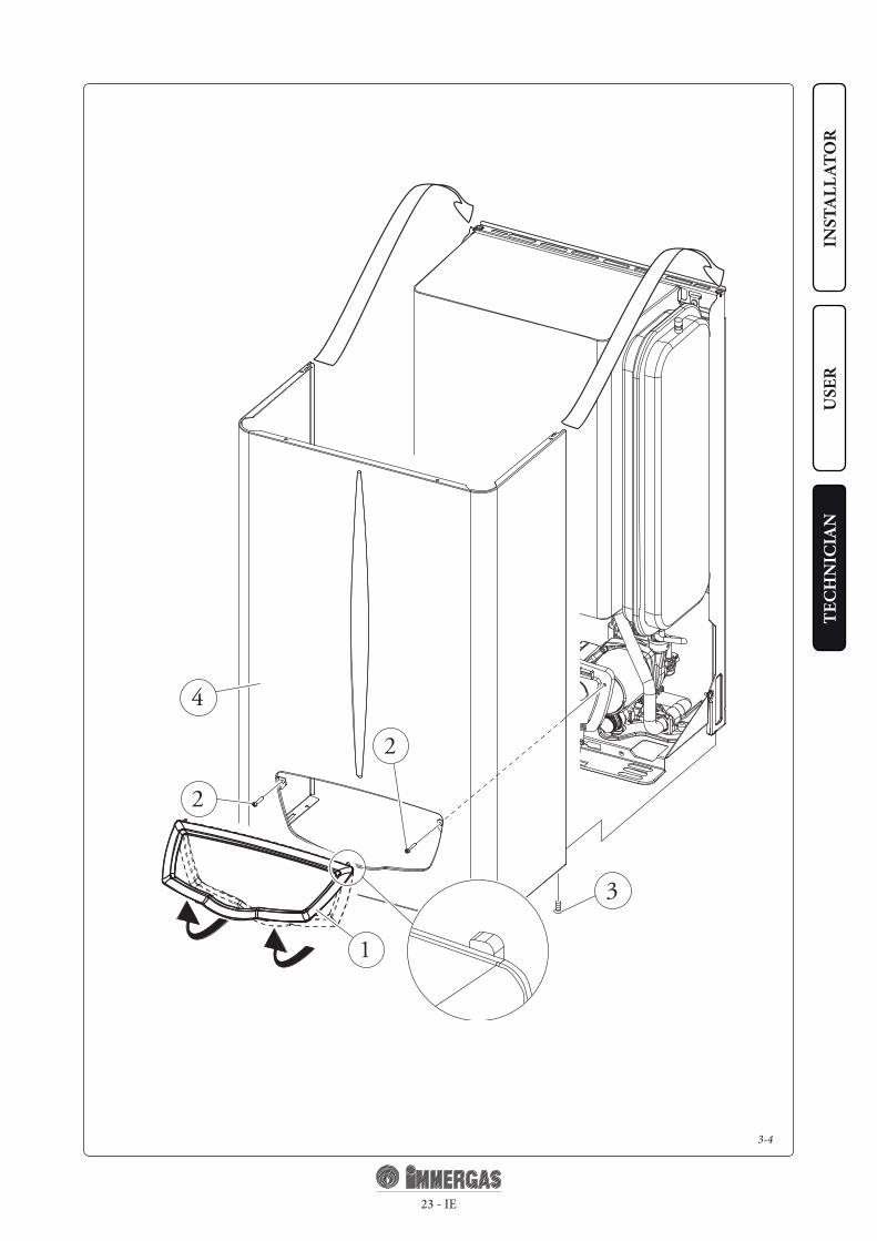
3-4
3
2
2
4
1
23 - IE
INST
ALL
ATO
RU
SER
TECH
NIC
IAN

24 - IE
INST
ALL
ATO
RU
SER
TECH
NIC
IAN
METHANE (G20) BUTANE (G30) PROPANE (G31)
HEATING POWER
HEATING
+
DOME-STIC HOT
WATER.
BURNER GAS FLOW
RATE
PRESS. BURNERNOZZLES
BURNER GAS FLOW
RATE
PRESS. BURNERNOZZLES
BURNER GAS FLOW
RATE
PRESS. BURNERNOZZLES
(kW) (kcal/h) (m3/h) (mbar) (mm H2O) (kg/h) (mbar) (mm H2O) (kg/h) (mbar) (mm H2O)
23,8 20468 2,70 11,40 116,3 2,01 28,20 287,6 1,98 36,30 370,223,0 19780 2,61 10,65 108,6 1,94 26,30 268,2 1,91 33,97 346,421,9 18806 2,48 9,65 98,4 1,85 23,76 242,3 1,82 30,84 314,521,0 18060 2,38 8,92 91,0 1,78 21,93 223,6 1,75 28,58 291,520,0 17200 2,27 8,13 82,9 1,70 19,94 203,3 1,67 26,11 266,219,0 16340 2,16 7,39 75,3 1,61 18,07 184,3 1,59 23,77 242,418,0 15480 2,06 6,69 68,2 1,53 16,31 166,3 1,51 21,56 219,817,0 14620 1,95 6,02 61,4 1,45 14,65 149,4 1,43 19,46 198,516,0 13760 1,84 5,40 55,1 1,37 13,10 133,6 1,35 17,48 178,315,0 12900 1,74 4,82 49,1 1,30 11,65 118,8 1,27 15,61 159,214,0 12040 1,63 4,27 43,5 1,22 10,28 104,9 1,20 13,85 141,213,0 11180 1,52 3,75 38,3 1,14 9,01 91,9 1,12 12,18 124,312,0 10320 1,42 3,27 33,4 1,06 7,83 79,9 1,04 10,62 108,311,5 9847 1,36 3,03 30,9 1,01 7,24 73,8 1,00 9,82 100,210,0 8600
DOME-STIC HOT
WATER.
1,19 2,36 24,1 0,89 5,62 57,3 0,87 7,62 77,79,0 7740 1,07 1,95 19,9 0,80 4,64 47,3 0,78 6,25 63,78,0 6880 0,95 1,59 16,3 0,71 3,79 38,6 0,70 5,02 51,27,0 6020 0,83 1,27 13,0 0,62 3,04 31,0 0,61 3,91 39,96,8 5848 0,81 1,22 12,4 0,60 2,91 29,7 0,59 3,71 37,8
3.17 VARIABLE HEAT POWER.N.B.: the pressures indicated in the table repre-sent the difference in existing pressures between the gas valve outlet and the combustion chamber. The adjustments should therefore, be carried out using a differential manometer (small “U”-shaped column or digital manometer) with the probes inserted in the pressure test gas valve outlet and on the sealed chamber positive pres-sure test. The power data in the table has been obtained with intake-exhaust pipe measuring 0.5 m in length. Gas flow rates refer to heating power below a temperature of 15°C and at a pressure of 1013 mbar. Burner pressure values refer to use of gas at 15°C.
3.18 COMBUSTION PARAMETERS.
G20 G30 G31Gas nozzle diameter mm 1,35 0,79 0,79supply pressure mbar (mm H2O) 20 (204) 29 (296) 37 (377)Mass flow of fumes at nominal power kg/h 53 53 55Mass flow of fumes at min. power kg/h 52 53 54CO2 at Q. Nom./Min. % 6,95 / 1,95 8,00 / 2,24 7,66 / 2,20CO at 0% di O2 at Q. Nom./Min. ppm 79 / 140 95 / 147 63 / 137NOX at 0% di O2 at Q. Nom./Min. ppm 55 / 34 77 / 30 78 / 30Temperature of fumes at nominal output °C 110 112 109Temperature of fumes at minimum output °C 96 93 95

25 - IE
INST
ALL
ATO
RU
SER
TECH
NIC
IAN
Nominal heat input kW (kcal/h) 25,5 (21914)DHW minimum heat input kW (kcal/h) 7,6 (6578)CH minimum heat input kW (kcal/h) 12,8 (11045)Nominal heat output (useful) kW (kcal/h) 23,8 (20468)DHW minimum heat output (useful) kW (kcal/h) 6,8 (5848)CH minimum heat output (useful) kW (kcal/h) 11,5 (9847)Efficiency at 100% heat output % 93,4Efficiency at 30% nominal heat output load % 90,2Heat loss at case with burner On/Off % 0,60 / 0,46Heat loss at flue with burner On/Off % 6,00 / 0,03Heating circuit max. working pressure bar 3Heating circuit max. working temperature °C 90Adjustable heating temperature °C 35 - 80Total volume system heating expansion vessel l 4,2Expansion vessel pre-charge bar 1Generator water capacity l 0,7Total head available with 1000 l/h flow rate kPa (m H2O) 30,4 (3,10)Hot water production useful heat output kW (kcal/h) 23,8 (20468)Domestic hot water adjustable temperature °C 35 - 55Domestic circuit flow limiter at 2 bar l/min 7,1Min. pressure (dynamic) domestic hot water circuit bar 0,3Domestic hot water circuit max. working pressure bar 10Minimum D.H.W. flow rate l/min 1,7Specific flow rate (ΔT 30°C) l/min 10,5Continuous flow rate (ΔT 30°C) l/min 11,1Weight of full boiler kg 29,7Weight of empty boiler kg 29Electric attachment V/Hz 230/50Nominal absorption A 0,67Installed electric power W 135Power absorbed by circulation pump W 85Power absorbed by fan W 34Equipment electrical system protection - IPX5DNOX class - 3Weighted NOX mg/kWh 139Weighted CO mg/kWh 61
Type of appliance C12 /C32 / C42 / C52 / C62 / C82 / B22 / B32
Category II2H3P / II2H3+
- Fume temperature values refer to an air inlet temperature of 15°C.
- The data relevant to domestic hot water per-formance refer to a dynamic inlet pressure of 2 bar and an inlet temperature of 15°C; the values are measured directly at the boiler outlet considering that to obtain the data declared mixing with cold water is necessary.
- The max. sound level emitted during boiler operation is < 55dBA. The sound level value is referred to semianechoic chamber tests with boiler operating at max. heat output, with extension of fume exhaust system according to product standards.
3.19 TECHNICAL DATA.


immergas.com
Immergas S.p.A.42041 Brescello (RE) - ItalyT. +39.0522.689011F. +39.0522.680617
This
instr
uctio
n bo
okle
t is m
ade o
f eco
logi
cal p
aper
.Co
d. 1
.032
131I
E re
v. 15
.036
178/
000
- 06/
2011