Industrial Filteration System by Ultra Drytech Engineering Limited Mumbai

IPS-E-PR-735
This Standard is the property of Iranian Ministry of Petroleum. All rights are reserved to the owner. Neither whole nor any part of this document may be disclosed to any third party, reproduced, stored in any retrieval system or transmitted in any form or by any means without the prior written consent of the Iranian Ministry of Petroleum.
ENGINEERING STANDARD
FOR
PROCESS DESIGN OF PLANT SOLID WASTE
TREATMENT AND DISPOSAL SYSTEMS
ORIGINAL EDITION
DEC. 1997
This standard specification is reviewed and updated by the relevant technical committee on Aug. 2005. The approved modifications are included in the present issue of IPS.

Dec. 1997
IPS-E-PR-735
1
CONTENTS : PAGE No.
0. INTRODUCTION ............................................................................................................................. 4
1. SCOPE ............................................................................................................................................ 5
2. REFERENCES ................................................................................................................................ 5
3. DEFINITIONS AND TERMINOLOGY ............................................................................................. 6
4. SYMBOLS AND ABBREVIATIONS ............................................................................................... 6
5. UNITS .............................................................................................................................................. 6
6. BASIC CONSIDERATIONS............................................................................................................ 6
6.1 Classification........................................................................................................................... 6
6.2 Methodology............................................................................................................................ 7
6.3 Sources .................................................................................................................................... 7
6.3.1 Solids in the crude oil supply......................................................................................... 7
6.3.2 Solids from surface water............................................................................................... 7
6.3.3 Solids in the water supply .............................................................................................. 7
6.3.4 Sanitary solid wastes ...................................................................................................... 7
6.3.5 Solids and sludges in waste water systems................................................................. 8
6.3.6 Catalytic processes catalysts ........................................................................................ 8
6.3.7 Solids from coking operations ....................................................................................... 8
6.3.8 Particulate matter and fly ash ........................................................................................ 8
6.3.9 Cleanout wastes .............................................................................................................. 9
6.3.10 Other sources ................................................................................................................ 9
6.4 Characteristics ........................................................................................................................ 9
6.5 Quantities................................................................................................................................. 9
7. SLUDGE HANDLING, TREATMENT AND REUSE ....................................................................... 9
7.1 General ..................................................................................................................................... 9
7.2 Sludge and Scum Pumping ................................................................................................. 10
7.2.1 Types and selection ...................................................................................................... 11
7.2.2 Application of pumps to types of sludge .................................................................... 12
7.3 Sludge Piping ........................................................................................................................ 13
7.4 Preliminary Operation Facilities .......................................................................................... 14
7.4.1 Sludge grinding ............................................................................................................. 14
7.4.2 Sludge degritting ........................................................................................................... 14
7.4.3 Sludge blending............................................................................................................. 14
7.4.4 Sludge storage ............................................................................................................... 15
7.5 Thickening (concentration) ...................................................................................................... 15
7.5.1 Application ..................................................................................................................... 16
7.5.2 Methods of applications................................................................................................ 16
7.5.3 Design considerations .................................................................................................. 16

Dec. 1997
IPS-E-PR-735
2
7.6 Stabilization ........................................................................................................................... 17
7.6.1 Design considerations .................................................................................................. 17
7.6.2 Lime stabilization........................................................................................................... 18
7.6.3 Heat treatment................................................................................................................ 18
7.6.4 Anaerobic sludge digestion ......................................................................................... 19
7.6.5 Aerobic sludge digestion.............................................................................................. 19
7.6.6 Composting .................................................................................................................... 20
7.7 Conditioning .......................................................................................................................... 21
7.8 Disinfection............................................................................................................................ 21
7.9 Dewatering ............................................................................................................................. 22
7.9.1 Application ..................................................................................................................... 22
7.9.2 Sludge dewatering methods......................................................................................... 22
7.9.3 Vacuum filteration ......................................................................................................... 23
7.9.4 Centrifugation ................................................................................................................ 24
7.9.5 Belt filter press............................................................................................................... 24
7.9.6 Filter presses ................................................................................................................. 24
7.9.7 Sludge drying beds ....................................................................................................... 25
7.9.8 Lagoons .......................................................................................................................... 25
7.10 Heat Drying .......................................................................................................................... 25
7.11 Thermal Reduction.............................................................................................................. 26
7.11.1 General.......................................................................................................................... 26
7.11.2 Thermal reduction process applications .................................................................. 26
7.12 Land Application of Sludge ............................................................................................... 27
7.13 Chemical Fixation ............................................................................................................... 28
8. FINAL SLUDGE AND SOLIDS CONVEYANCE, STORAGE AND DISPOSAL.......................... 28
8.1 General ................................................................................................................................... 28
8.2 Conveyance Methods ........................................................................................................... 29
8.2.1 General............................................................................................................................ 29
8.2.2 Pipeline ........................................................................................................................... 29
8.2.3 Truck ............................................................................................................................... 29
8.2.4 Barge............................................................................................................................... 29
8.2.5 Rail .................................................................................................................................. 30
8.2.6 Environmental considerations in sludge transportation........................................... 30
8.3 Sludge Storage...................................................................................................................... 30
8.3.1 General............................................................................................................................ 30
8.3.2 Sludge storage and basins ........................................................................................... 30
8.3.3 Sludge storage pads ..................................................................................................... 30
8.4 Final Disposal........................................................................................................................ 30
8.4.1 General............................................................................................................................ 30

Dec. 1997
IPS-E-PR-735
3
8.4.2 Landfilling....................................................................................................................... 31
8.4.3 Lagooning ...................................................................................................................... 31
8.5 Incineration ............................................................................................................................ 31
8.6 Ash Handling and Disposal ................................................................................................. 32
APPENDICES:
APPENDIX A TABLE A.1 - SOURCES OF SOLIDS AND SLUDGE FROM A CONVENTIONAL WASTE WATER TREATMENT PLANT ................................................ 33
APPENDIX B TYPICAL CHARACTERISTICS OF SOLIDS AND SLUDGE ................................ 34
TABLE B.1 ... CHARACTERISTICS OF SOLIDS AND SLUDGE PRODUCED DURING WASTE WATER TREATMENT ...................................................................................................................... 34
TABLE B.2 . TYPICAL CHEMICAL COMPOSITION AND PROPERTIES OF UNTREATED AND DIGESTED SLUDGE ........................................................................................................................ 35
TABLE B.3 TYPICAL METAL CONTENT IN WASTE WATER SLUDGE ............................ 36
APPENDIX C TYPICAL QUANTITIES AND CONCENTRATIONS OF SLUDGES .............................................................................................................. 37
TABLE C.1 - .... TYPICAL DATA FOR THE PHYSICAL CHARACTERISTICS AND QUANTITIES OF SLUDGE PRODUCED FROM VARIOUS WASTE WATER TREATMENT OPERATIONS AND PROCESSES .................................................................................................................................... 37
TABLE C.2 - ............EXPECTED SLUDGE CONCENTRATIONS FROM VARIOUS TREATMENT OPERATIONS AND PROCESSES .................................................................................................. 38

Dec. 1997
IPS-E-PR-735
4
0. INTRODUCTION
"Design of Miscellaneous Processes in OGP Industries" particularly involving in the Environmental Aspects are broad and contain various subjects of paramount importance.
Therefore, a group of process Engineering Standards are prepared to cover this subject. This group includes the following Standards:
STANDARD CODE STANDARD TITLE
IPS-E-PR-700 "Process Design of Crude Oil Electrostatic Desalters"
IPS-E-PR-725 "Process Design of Plant Waste Water Sewer Systems"
IPS-E-PR-730 "Process Design of Plant Waste Water Treatment and Recovery Systems"
IPS-E-PR-735 "Process Design of Plant Solid Waste Treatment & Disposal Systems"
This Engineering Standard Specification covers:
"PROCESS DESIGN OF PLANT SOLID WASTE TREATMENT & DISPOSAL SYSTEMS"

Dec. 1997
IPS-E-PR-735
5
1. SCOPE
This Engineering Standard Specification covers minimum requirements for the process design and engineering of plant solid waste treatment and disposal facilities in OGP Industries. This Engineering Standard does not deal with the disposal systems and treatment facilities pertaining to the air pollution aspects and covers only the water pollution features.
As far as Environmental Regulations are concerned, extent of application of all systems, facilities and/or methods as outlined in this Standard Specification shall be instructed by the Company for each project.
This Engineering Standard Specification shall be read in conjunction with the standards listed below:
STANDARD CODE STANDARD TITLE
IPS-E-GN-100 "Units"
IPS-E-CE-400 "Sewage Treatment"
IPS-C-CE-342 "Construction Works for Water Supply & Sewerage System"
IPS-M-CE-345 "Water Supply & Sewerage Equipment"
IPS-E-SF-880 "Water Pollution Control"
IPS-E-PR-725 "Process Design of Plant Waste Water Sewer Systems"
IPS-E-PR-730 "Process Design of Plant Waste Water Treatment and Recovery Systems"
Note: This standard specification is reviewed and updated by the relevant technical committee on Aug. 2005. The approved modifications by T.C. were sent to IPS users as amendment No. 1 by circular No. 271 on Aug. 2005. These modifications are included in the present issue of IPS.
2. REFERENCES
Throughout this Standard the following dated and undated standards/codes are referred to. These referenced documents shall, to the extent specified herein, form a part of this standard. For dated references, the edition cited applies. The applicability of changes in dated references that occur after the cited date shall be mutually agreed upon by the Company and the Vendor. For undated references, the latest edition of the referenced documents (including any supplements and amendments) applies.
IPS (IRANIAN PETROLEUM STANDARDS)
IPS-E-CE-400 "Sewage Treatment"
IPS-C-CE-342 "Construction Works for Water Supply & Sewerage System"
IPS-E-GN-100 "Units"
IPS-M-CE-345 "Water Supply & Sewerage Equipment"
IPS-E-SF-880 "Water Pollution Control"
IPS-E-PR-725 "Process Design of Plant Waste Water Sewer Systems"
IPS-E-PR-730 "Process Design of Plant Waste Water Treatment and Recovery Systems"

Dec. 1997
IPS-E-PR-735
6
IPS-G-SF-130 "Solid Waste Disposal"
3. DEFINITIONS
For definition of the particular terms/words of this Standard Specification, reference should be made to the latest revision of the following standards/publications:
API Vol. 1, "Manual on Disposal of Refinery Wastes, Liquid Wastes"
IPS-E-CE-380 "Sewerage and Surface Water Drainage System"
IPS-E-CE-390 "Rain & Foul Water Drainage of Buildings"
IPS-E-CE-400 "Sewage Treatment"
IPS-E-PR-725 "Process Design of Plant Waste Water Sewer Systems"
IPS-E-PR-730 "Process Design of Plant Waste Water Treatment and Recovery Systems"
4. SYMBOLS AND ABBREVIATIONS
Symbols and abbreviations referred to in this Standard are as follows:
BOD5 The 5 Day Biochemical Oxygen Demand at 20°C.
BS&W Basic Sediment and Water.
COD Chemical Oxygen Demand.
DN Diameter Nominal, in (mm).
DO Dissolved Oxygen.
EPA Environmental Protection Agency.
L/s Liter per second.
m meter.
OGP Oil, Gas and Petrochemical.
PFRP Process to Further Reduce Pathogens.
ppmm Parts per million by mass, in (mg/kg) and/or (mg/L) in case of water.
PSRP Process to Significantly Reduce Pathogens.
r/min (rpm) rotations per minute.
SS Suspended Solids.
TDS Total Dissolved Solids.
TS Total Solids.
5. UNITS
This Standard is based on International System of Units (SI) as per IPS-E-GN-100, except where otherwise specified.
6. BASIC CONSIDERATIONS
6.1 Classification
Solid wastes include those suspended in liquids and are classified in the following categories in the

Dec. 1997
IPS-E-PR-735
7
order of increasing difficulty in disposal:
a) Inert dry solids, e.g., trash, silt, spent cracking catalyst.
b) Combustible dry solids, e.g., trash, waste paper, scrap lumber.
c) Sludges containing water and solids, e.g., water softener sludges, sanitary sludges.
d) Sludges containing oil, e.g., spent clays.
e) Sludges containing oil, water, and solids, e.g., tank bottoms, oil-water separator bottoms.
6.2 Methodology
For proper evaluation and selection of solid waste disposal the following procedures shall be performed:
a) Tabulation of sources.
b) Sludge production rates and quantities.
c) Physical characteristics such as pumpability, concentration factor, etc.
d) Analyses for water, oil and solids contents, volatiles, and ash.
e) Analyses of the water component for pH, sulfide, acidity or alkalinity, lead, and other constituents having potentially significant effects on water pollution.
f) Analyses of the solids component for combustible and non-combustible content and for size distribution of the dry solids.
g) Heating value of sludge (on dry basis).
6.3 Sources
6.3.1 Solids in the crude oil supply
All crude oils contain some basic sediment and water (BS &W) which is generally composed of a mixture of water, iron rust, iron sulfides, clay, sand, and so forth produced with the crude oil or picked up in transit. Part of the BS &W is charged to the crude oil Unit and may settle out in the desalter, entering the oily water sewer system along with the desalter effluent. The balance will settle out in storage tanks, resulting in eventual tank-cleaning problems.
6.3.2 Solids from surface water
Process waters and all other special drainages throughout the plant/refinery shall be isolated from surface run-off. The surface drainage shall be collected in a dedicated and separate clean storm water sewer system (see IPS-E-PR-725). Extensive efforts shall be made to the segregation of the surface drainages and avoiding the contamination or mixing with the oily water sewers.
6.3.3 Solids in the water supply
Silt may enter in the water supply. Depending on the source of the supplied water to the plant/refinery and the characteristics and impurities, provision of sedimentation before the water is used shall be investigated. Special attention shall be made to the reducing of deposition of solids in cooling tower basins, heat exchangers and other consumers and, also to prevent these solids from entering oily water sewers.
6.3.4 Sanitary solid wastes
Sanitary wastes should be segregated from all other types of drainage systems (see Article 2 of this Standard Specification for applicable sources of disposal and treatment of sanitary sewer).

Dec. 1997
IPS-E-PR-735
8
6.3.5 Solids and sludges in waste water systems
According to the type of plant and the method of plant operation, the sources of solids in a waste water treatment plant can be realized. The principal sources of solids and sludge and the types generated in a conventional waste water treatment plant is demonstrated in Table A.1 of Appendix A. Solids may also be formed by interaction of waste streams in the sewer. Waste waters contain metal ions, such as iron, aluminum, copper; magnesium and etc. from corrosion of the process equipment, chemicals used in treating cooling water, salts in the water intake, and chemicals used in processing. Insoluble metal hydroxide floc may be formed when alkaline wastes are discharged and raise the pH of waste water above neutral. The wastes containing a considerable concentrations of phenols, sulfides, emulsifying agents and alkalines shall be segregated. In general discharging of any material to the oily sewer system or other drainage systems should be investigated for the final waste treatment and disposal targets.
6.3.6 Catalytic processes catalysts
Catalyst can be appeared in the sewer systems in the plants with catalytic processes applications. Means shall be provided to minimize catalyst disposal. Hopper trucks or covered portable containers shall be provided to prevent catalyst fines from becoming airborne. In some cases spent catalyst is slurred with water and pumped directly to ponds where the solids are settled. Spent solid catalysts which contain, platinum or other valuable metals shall be returned to the manufacturer for recovery.
6.3.7 Solids from coking operations
6.3.7.1 Coke fines
Water used to remove coke from coke chambers in delayed coking Units shall be recirculated through a settling basin to remove entrained coke fines. The basin can be located near the coke storage pile so that storm water will drain through the basin to recover coke washed from the storage area. To clean the basin, coke can be transferred directly to the storage pile with appropriate equipment.
6.3.7.2 Wax tailings
Wax tailings from coking processes present a very difficult disposal problem in the sewer systems. Wax tailings disposal to the oily sewer system shall be avoided. Wax deposits may form to clog the oily water sewer or to reduce the capacity of the oil water separators. In some cases, the wax tailings will rise and be partially absorbed in the oil layer, causing slop oil treating problems. Investigations shall be made to provide facilities to remove wax tailings before discharging to the sewer system. The coker blowdown system may include a scrubber in which a light oil, such as light cycle oil is recirculated to dissolve wax tailings and remove them from the water. When the API gravity of the light oil has reached a certain point, the oil shall be returned to the hot-oil system via the fractionator and be replaced by a new charge.
6.3.8 Particulate matter and fly ash
Particulate matter from collectors is sometimes commercially valuable either directly or after further treatment. Therefore, special attention shall be made to collect the particles for reuse purposes such as:
- Addition to concrete in small amount;
- using as constituent of clay bricks;
- using as a soil conditioner.

Dec. 1997
IPS-E-PR-735
9
6.3.9 Cleanout wastes
Solids from cleanout operations contain normally a considerable amounts of various metals and should not be sent to the oily water system.
6.3.10 Other sources
Other sources of the solid wastes such as the following shall be taken into consideration:
- Storage tank drains.
- Process Unit drains.
- Catalyst contaminated streams.
- Others.
6.4 Characteristics
The characteristics vary depending on the origin of the solids and sludge, the amount of aging that has taken place, and the type of processing to which they have been subjected. Some of the physical characteristics of sludges are summarized in Tables B.1, B.2, and B.3 of Appendix B.
6.5 Quantities
The quantity of solids entering the waste water treatment plant is fluctuated over a wide range. To ensure capacity capable of handling these variations, the following factors shall be taken into consideration:
a) The average and maximum rates of sludge production.
b) The potential storage capacity of the treatment Units within the plant.
c) Capabilities to dump short-term peak loads (e.g., by sufficient capacity of equalization basin).
Data on the quantities of sludge produced from various processes and operations and also sludge concentrations are shown in Table C.1 of Appendix C.
7. SLUDGE HANDLING, TREATMENT AND REUSE
7.1 General
In selecting the appropriate methods of sludge processing, reuse, and disposal, special consideration must be given to the regulations controlling the disposal of sludge from waste water treatment plants. The following main disposal targets shall be investigated :
- Application of sludge to agricultural and non-agricultural land;
- distribution and marketing;
- monofilling;
- surface disposal;
- incineration.
The sludge processing and disposal methods are listed in Table 1. Thickening (concentration), conditioning, dewatering, and drying are used primarily to remove moisture from sludge; digestion, composting, incineration, wet air oxidation, and vertical tube reactors are used primarily to treat or stabilize the organic material in the sludge.

Dec. 1997
IPS-E-PR-735
10
7.2 Sludge and Scum Pumping
Sludge produced in waste water treatment plants must be conveyed from one plant point to another in conditions ranging from a watery sludge or scum to a thick sludge.
For each type of sludge and pumping application, a different type of pump may be needed. The application and selection of the various types of sludge pumps are summarized below:
TABLE 1 - SLUDGE-PROCESSING AND DISPOSAL METHODS UNIT OPERATION, UNIT PROCESS,
OR TREATMENT METHOD FUNCTION
Preliminary operations Sludge grinding Sludge degritting Sludge blending Sludge storage Thickening Gravity thickening Flotation thickening Centrifugation Gravity belt thickening Rotary drum thickening Stabilization Lime stabilization Heat treatment Anaerobic digestion Aerobic digestion Composting Conditioning Chemical conditioning Heat treatment Disinfecting Pasteurization Long-term storage Dewatering Vacuum filter Centrifuge Belt filter press Filter press Sludge drying beds Lagoons Heat Drying Flash dryer Spray dryer Rotary dryer Multiple hearth dryer Multiple-effect evaporator Thermal Reduction Multiple-hearth incineration Fluidized-bed incineration Co-incineration with solid wastes Wet-air oxidation Vertical, deep-well reactor Ultimate disposal Land application Distribution and marketing Chemical fixation Landfill Lagooning
Size reduction Grit removal Blending Storage Volume reduction Volume reduction Volume reduction Volume reduction Volume reduction Stabilization Stabilization Stabilization, mass reduction Stabilization, mass reduction Stabilization, product recovery Sludge conditioning Sludge conditioning Disinfection Disinfection Volume reduction Volume reduction Volume reduction Volume reduction Volume reduction Storage, volume reduction Mass and volume reduction Mass and volume reduction Mass and volume reduction Mass and volume reduction Mass and volume reduction Volume reduction, resource recover Volume reduction Volume reduction Stabilization, Volume reduction Stabilization, Volume reduction Final disposal Beneficial use Beneficial use, final disposal Final disposal Volume reduction, final disposal

Dec. 1997
IPS-E-PR-735
11
7.2.1 Types and selection
7.2.1.1 Plunger pumps
Plunger pumps have been used frequently and, if rugged enough for the service, have proved to be quite satisfactory. The advantages of plunger pumps are as follows:
a) Pulsating action of simplex and duplex pumps tends to concentrate the sludge in the hoppers ahead of the pumps and resuspend solids in pipelines when pumping at low velocities.
b) They are suitable for suction lifts up to 3 m and are self priming.
c) Low pumping rates can be used with large port openings.
d) Positive delivery is provided, unless some object prevents the ball check valves from seating.
e) They have constant but adjustable capacity, regardless of large variations in pumping head.
f) High discharge heads may be provided.
g) Heavy solids concentrations may be pumped if the equipment is designed for the load conditions.
The range of plunger pumps capacities are from 2.5 to 3.8 L/s per plunger and they are supplied with one, two, or three plungers (called simplex, duplex, or triplex units).
Pump speeds should be between 40 and 50 r/min (rpm). The pumps should be designed for a minimum head of 24 m in small plants and 35 m or more in large plants because of accumulations of grease in sludge lines cause a progressive increase in head with use.
7.2.1.2 Progressive cavity pumps
The progressive cavity pumps are normally used for all types of sludges. The pump is self-priming at suction lifts up to 8.5 m, but it must not be operated dry because it will burn out the rubber stator. It is available in capacities up to 75 L/s and may be operated at discharge heads of 137 m on sludge. For primary sludges, a grinder normally precedes these pumps. The pumps are expensive to maintain because of wear on the rotors and the stators, particularly in primary sludge-pumping applications where grit is present. Advantages of these pumps are:
a) Easily controlled flowrates;
b) minimum pulsation; and,
c) relatively simple operation.
7.2.1.3 Centrifugal pumps
Centrifugal pumps of non-clog design are commonly used. The selected pumps must have sufficient clearance to pass the solids without clogging and have a small enough capacity to avoid pumping a sludge diluted by large quantities of waste water overlying the sludge blanket. Throttling the discharge to reduce the capacity is impractical because of frequent stoppages; hence, it is absolutely essential that these pumps be equipped with variable-speed drives. For pumping primary sludge in large plants, centrifugal pumps of special design-torque flow, screw feed, and bladeless should be used. Screw feed and bladeless pumps have not be used very much in recent applications because of the successful use of torque-flow pumps.
Torque-flow pumps have fully recessed impellers and are very effective in conveying sludge. The size of particles that can be handled is limited only by the diameter of the suction or discharge openings. Pumps used in sludge service should have nickel or chrome abrasion resistant volute and impellers. The pumps can operate only over a narrow head range at a given speed, so the system operating conditions must be evaluated carefully. Variable speed control should be used

Dec. 1997
IPS-E-PR-735
12
where the pumps are expected to operate over a wide range of head conditions. For high pressure applications, multiple pumps may be used and connected together in series. For returning activated sludge to the aeration tanks, slow speed centrifugal, mixed flow pumps and screw pumps are commonly used.
7.2.1.4 Diaphragm pumps
Diaphragm pumps are relatively low capacity and low head.
7.2.1.5 High pressure piston pumps
High pressure piston pumps are used in high pressure applications such as pumping sludge long distances and are very expensive. Several types of piston pumps have been developed for high pressure applications and are similar in action to plunger pumps. Advantages of these types of pumps are:
a) They can pump relatively small flowrates at high pressures, up to 13800 kPa (ga),
b) large solids up to the discharge pipe diameter can be passed,
c) a range of solids concentrations can be handled, and,
d) the pumping can be accomplished in a single stage.
7.2.1.6 Rotary-lobe pumps
Rotary-lobe pumps are positive displacement pumps in which two rotating, synchronous lobes push the fluid through the pump. Rotational speed and shearing stresses are low. For sludge pumping, lobe shall be made of hard metal or hard rubber. The advantage is that lobe replacement is less costly than rotor and stator replacement for progressive cavity pumps. Rotary-lobe pumps, like other positive displacement pumps, must be protected against pipeline obstructions.
7.2.2 Application of pumps to types of sludge
Types of sludge that are pumped include primary, chemical, and trickling-filter sludges and activated, thickened, and digested sludges. Scum that accumulates at various points at a treatment plant must also be pumped. The application of pumps to types of sludge is summarized in Table 2.

Dec. 1997
IPS-E-PR-735
13
TABLE 2 - APPLICATION OF PUMPS TO TYPES OF SLUDGE TYPE OF SLUDGE OR
SOLIDS APPLICABLE PUMP COMMENT
Ground screenings Grit Scum Primary sludge Chemical precipitation Digested sludge Trickling-filter humus sludge Return or waste activated sludge Thickened or concentrated sludge
Pumping screenings should be avoided Torque-flow centrifugal Plunger; progressive cavity; diaphragm; centrifugal Plunger; torque-flow centrifugal; diaphragm; progressive cavity; rotary-lobe Same as for primary sludge Plunger; torque-flow centrifugal; progressive cavity; diaphragm; high-pressure piston; rotary-lobe Nonclog and torque-flow centrifugal; progressive cavity; plunger; diaphragm Nonclog and torque-flow centrifugal; progressive cavity; diaphragm Plunger, progressive cavity; diaphragm; high-pressure piston; rotary-lobe
Pneumatic ejectors may be used. The abrasive character of grit and the presence of rags make grit difficult to handle. Hardened casings and impellers should be used for torque-flow pumps. Pneumatic ejectors may also be used. Scum is often pumped by the sludge pumps; valves are manipulated in the scum and sludge limes to permit this. In larger plants, separate scum pumps are used. Scum mixers are often used to ensure homogeneity prior to pumping. Pneumatic ejectors may also be used. In most cases, it is desirable to obtain as concentrated a sludge as practicable from primary sedimentation tanks, usually by collecting the sludge in hoppers and pumping intermittently, allowing the sludge to collect and consolidate between pumping periods. The character of untreated primary sludge will vary considerably, depending on the characteristics of the solids in the wastewater and the types of treatment Units and their efficiency. Where biological treatment follows, the quantity of solids from: 1) Waste activated sludge, 2) humus sludge from settling tanks following trickling filters, 3) overflow liquors from digestion tanks, and, 4) centrate or filtrate return from dewatering operations will also affect the sludge characteristics. In many cases, the character of the sludge is not suitable for the use of conventional nonclog centrifugal pumps. Well-digested sludge is homogeneous, containing 5 to 8% solids and a quantity of gas bubbles, but may contain up to 12% solids. Poorly digested sludge may be difficult to handle. If good screening and grit removal is provided, nonclogy centrifugal pumps may be considered. Sludge is usually of homogeneous character and can be easily pumped. Sludge is dilute and contains only fine solids so that nonclog pumps may commonly be used. For nonclog pumps, slow speeds are recommended to minimize the breakup of flocculant particles. Positive displacement pumps are most applicable for concentrated sludge because of their ability to generate movement of the sludge mass. Torque-flow pumps may be used but may require the addition of flushing or dilution facilities.
7.3 Sludge Piping
7.3.1 In treatment plants, conventional sludge piping should not be smaller than DN 150 (6 inch), although smaller diameter glass-lined pipes have been used successfully.
7.3.2 Pipe sizes need not be larger than DN 200 (8 inch) unless the velocity exceeds 1.5 to 1.8 m/s, in which case, the pipe shall be sized to maintain the velocity. Gravity sludge withdrawal lines should not be less than DN 200 (8 inch) in diameter.
7.3.3 A number of cleanouts in the form of plugged tees or crosses instead of elbows shall be installed so that the lines can be rodded if necessary.

Dec. 1997
IPS-E-PR-735
14
7.3.4 Pump connections should not be smaller than DN 100 (4 inch) in diameter.
7.3.5 Pump selection shall consider build-up of head due to grease accumulations at the inside of piping. In some plants provisions may also be made for melting the grease by circulating hot water, steam or digester supernatant through the main sludge lines.
7.3.6 In the design of long sludge lines, special design features should be considered including:
a) Providing two pipes unless a single pipe can be shut-down for several days without causing problems;
b) providing for external corrosion and pipe loads;
c) adding facilities for applying dilution water for flushing the line;
d) providing means to insert a pipe cleaner at the treatment plant;
e) including provisions for steam injections;
f) providing air relief and blow-off valves for the high and low points, respectively; and,
g) considering the potential effects of waterhammer.
7.4 Preliminary Operation Facilities
Sludge grinding, degritting, blending, and storage are necessary to provide a relatively constant, homogeneous feed to sludge processing facilities. Blending and storage can be accomplished either in a single Unit designed to do both or separately in other plant components.
7.4.1 Sludge grinding
Some of the processes that must be preceded by sludge grinders for the purpose of preventing clogging are:
a) Pumping with progressive cavity pumps;
b) solid bowl centrifuges;
c) belt filter press;
d) heat treatment; and,
e) chlorine oxidation (for enhancing chlorine contact with sludge particles).
Slow speed, more durable and reliable grinders shall be applied. The design shall include improved bearings and seals, hardened steel cutters, overload sensors, and mechanisms that reverse the cutter rotation to clear obstructions or shutdown the Unit if the obstruction can not be cleared.
7.4.2 Sludge degritting
In some plants where separate grit removal facilities are not used ahead of the primary sedimentation tanks or where the grit removal facilities are not adequate to handle peak flows and peak grit loads, the grit removal facilities should be provided before further processing of the sludge. Where further thickening of the primary sludge is desired, a practical consideration is sludge degritting. The most effective method of degritting is through the application of centrifugal forces in a flowing system to achieve separation of grit particles from the organic sludge. Such separation is achieved through the use of cyclone degritters, which have no moving parts. The efficiency of the cyclone degritter is affected by pressure and by the concentration of the organic in the sludge. To obtain effective grit separation, the sludge must be relatively dilute. As the sludge concentration increases, the particle size that can be removed decreases.
7.4.3 Sludge blending
Sludge is blended (if required) to produce a uniform mixture to downstream operations and processes. Uniform mixtures are most important in short detention time systems, such as sludge

Dec. 1997
IPS-E-PR-735
15
dewatering, heat treatment, and incineration. Special attention shall be given to segregation of oily and non-oily sludges.
Sludge from the various sources can be blended in the several ways.
a) In primary settling tanks:
The same type (oily or non-oily) sludges from secondary or advanced waste water treatment sludges can be returned to the primary settling tanks, where they will settle and mix with the primary sludge.
b) In pipes:
This procedure require careful control of sludge sources and feed rates to ensure the proper blend.
c) In sludge processing facilities with long detention times:
Aerobic and anaerobic digesters (complete-mix type) can blend the feed sludges uniformly.
d) In a separate blending tank:
This practice provides the best opportunity to control the quality of the blended sludges.
In treatment plants of less than 140 m³/h capacity, blending is usually accomplished in the primary settling tanks. In large facilities, optimum efficiency is achieved by separately thickening sludges before blending. Blending tanks should be equipped with mechanical mixers and baffles to ensure good mixing.
7.4.4 Sludge storage
Sludge storage must be provided to smooth out fluctuations in the rate of sludge production and to allow sludge to accumulate during periods when subsequent sludge processing facilities are not operating. Sludge storage shall be provided a head of the following processes to establish a uniform feed rate:
a) Lime stabilization,
b) Heat treatment,
c) Mechanical dewatering,
d) Drying,
e) Thermal reduction.
Sludge tanks may be sized to retain the sludge for a period of several hours to a few days. If sludge is stored longer than two or three days, it will deteriorate and will be more difficult to dewater. Sludge is often aerated to prevent septicity and to promote mixing. Means shall be provided to reduce and control the odors from sludge storage.
7.5 Thickening (concentration)
Thickening should be used to increase the solids content of sludge by removing a portion of the liquid fraction before the land disposal of the sludge or other applications as required. Representative values of percent total solids from various treatment operations or processes are shown in Table C.2 of Appendix C. The sludge thickening methods are described in Table. 3.

Dec. 1997
IPS-E-PR-735
16
7.5.1 Application
On large projects where sludge must be transported a significant distance, such as to a separate plant for processing, a reduction in sludge volume will result in a reduction of pipe size and pumping costs. Volume reduction is very desirable when liquid sludge is transported by tank trucks for direct application to land as a soil conditioner. In treatment plants with less than 140 m³/h capacity, separate sludge thickening may not be required. In small plants, gravity thickening is accomplished in the primary settling tank or in the sludge digestion Units, or both.
7.5.2 Methods of applications
The following thickening methods depending on the type of sludge can be applied (see Table 3):
- Gravity.
- Dissolved air flotation.
- Imperforate basket centrifuge.
- Solid bowl centrifuge.
- Gravity belt thickener.
- Rotary drum thickener.
For gravity thickening, a circular tank shall be used. Provisions for dilution water and occasional chlorine addition shall be considered to improve process performance.
For flotation type, only dissolved air flotation shall be used. Higher loadings can be used with flotation thickeners than are permissible with gravity thickeners because of the rapid separation of solids from the waste water.
7.5.3 Design considerations
7.5.3.1 In designing thickening facilities, it is important to provide adequate capacity to meet peak demands and prevent septicity, with its attendant odor problems, during the thickening process.
7.5.3.2 To maintain aerobic conditions in gravity thickeners, provisions should be made for adding 24 to 30 m³/m².d of final effluent to the thickening tank.
7.5.3.3 Minimum solids loadings shall be used for design of thickeners.
7.5.3.4 The use of polymers as flotation aids is effective in increasing the solids recovery in the floated sludge and in reducing the recycle loads.
Dec. 1997
IPS-E-PR-735
17
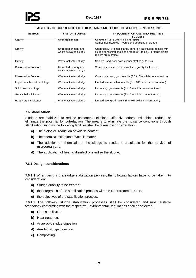
TABLE 3 - OCCURRENCE OF THICKENING METHODS IN SLUDGE PROCESSING METHOD TYPE OF SLUDGE FREQUENCY OF USE AND RELATIVE
SUCCESS Gravity Gravity Gravity Dissolved-air flotation Dissolved-air flotation Imperforate basket centrifuge Solid bowl centrifuge Gravity belt thickener Rotary drum thickener
Untreated primary Untreated primary and waste activated sludge Waste activated sludge Untreated primary and waste activated sludge Waste activated sludge Waste activated sludge Waste activated sludge Waste activated sludge Waste activated sludge
Commonly used with excellent results. Sometimes used with hydroclone degritting of sludge. Often used. For small plants, generally satisfactory results with sludge concentrations in the range of 4 to 6%. For large plants, results are marginal. Seldom used; poor solids concentration (2 to 3%). Some limited use; results similar to gravity thickeners. Commonly used; good results (3.5 to 5% solids concentration). Limited use; excellent results (8 to 10% solids concentration). Increasing; good results (4 to 6% solids concentration). Increasing; good results (3 to 6% solids concentration). Limited use; good results (5 to 9% solids concentration).
7.6 Stabilization
Sludges are stabilized to reduce pathogens, eliminate offensive odors and inhibit, reduce, or eliminate the potential for putrefaction. The means to eliminate the nuisance conditions through stabilization such as the following facilities shall be taken into consideration.
a) The biological reduction of volatile content.
b) The chemical oxidation of volatile matter.
c) The addition of chemicals to the sludge to render it unsuitable for the survival of microorganisms.
d) The application of heat to disinfect or sterilize the sludge.
7.6.1 Design considerations
7.6.1.1 When designing a sludge stabilization process, the following factors have to be taken into consideration:
a) Sludge quantity to be treated;
b) the integration of the stabilization process with the other treatment Units;
c) the objectives of the stabilization process.
7.6.1.2 The following sludge stabilization processes shall be considered and most suitable technology conforming with the respective Environmental Regulations shall be selected.
a) Lime stabilization.
b) Heat treatment.
c) Anaerobic sludge digestion.
d) Aerobic sludge digestion.
e) Composting.

Dec. 1997
IPS-E-PR-735
18
7.6.2 Lime stabilization
7.6.2.1 Sufficient lime shall be added to untreated sludge to raise the pH to 12 or higher. The methods concerned shall be evaluated for proper place of lime injection.
7.6.2.2 The minimum criteria for lime stabilization in lime pre-treatment method is that to maintain the pH above 12 for about two hours so as to ensure pathogen destruction and to provide enough residual alkalinity so that the pH does not drop below 11 for several days.
7.6.2.3 Testing should be preformed for specific applications to determine the actual dosage requirements.
7.6.2.4 Because lime stabilization does not destroy the organic necessary for bacteria growth, the sludge must be treated with an excess of lime or disposed of before the pH drops significantly. An excess dosage of lime may range up to 1.5 times the amount needed to maintain the initial pH of 12.
7.6.2.5 Post-lime stabilization has several significant advantages when compared to pre-lime stabilization such as:
a) Dry lime can be used; therefore, no additional water is added to the dewatered sludge;
b) there are no special requirements for dewatering;
c) scaling problems and associated maintenance problems of lime sludge dewatering equipment are eliminated.
7.6.2.6 Adequate mixing shall be provided for a post-lime stabilization system so as to avoid pockets of putrescible material.
7.6.3 Heat treatment
7.6.3.1 Heat treatment which is classified also as conditioning process shall be designed for continuous process and shall consider heating of the sludge in a pressure vessel to temperatures up to 260°C at pressures up to 2760 kPa (ga) for short periods of time (approximately 30 minutes). The heat treatment process is most applicable to biological sludges that may be difficult to stabilize or condition by other means.
7.6.3.2 Advantages for heat treatment process are as follows:
a) The solids content of the dewatered sludge can range from 30 to 50 percent, depending on the degree of oxidation achieved;
b) the processed sludge does not normally require chemical conditioning.
c) the process stabilizes sludge and will destroy most pathogenic organisms;
d) the processed sludge will have a heating value of 28 to 30 kJ/g of volatile solids;
e) the process is relatively insensitive to changes in sludge composition.
7.6.3.3 The major disadvantages are:
a) High capital cost;
b) close supervision, skilled operators and a strong preventative maintenance program are required;
c) the process produces sidestreams with high concentrations of organic, ammonia nitrogen and color;
d) significant odorous gases are produced that require extensive containment, treatment, and/or destruction.
Dec. 1997
IPS-E-PR-735
19
e) scale formation in the heat exchangers, pipes and reactor requires acid washing or high pressure water jets.
7.6.4 Anaerobic sludge digestion
7.6.4.1 The following processes can be investigated for proper process selection based on the sludge concentration, rate and characteristics.
a) Standard-rate digestion.
b) Single stage high-rate digestion.
c) Two stage digestion.
d) Separate sludge digestion.
7.6.4.2 The design shall be based on:
a) The concept of mean cell-residence time;
b) the use volumetric loading factors;
c) observed volume reduction; and
d) loading factors based on population.
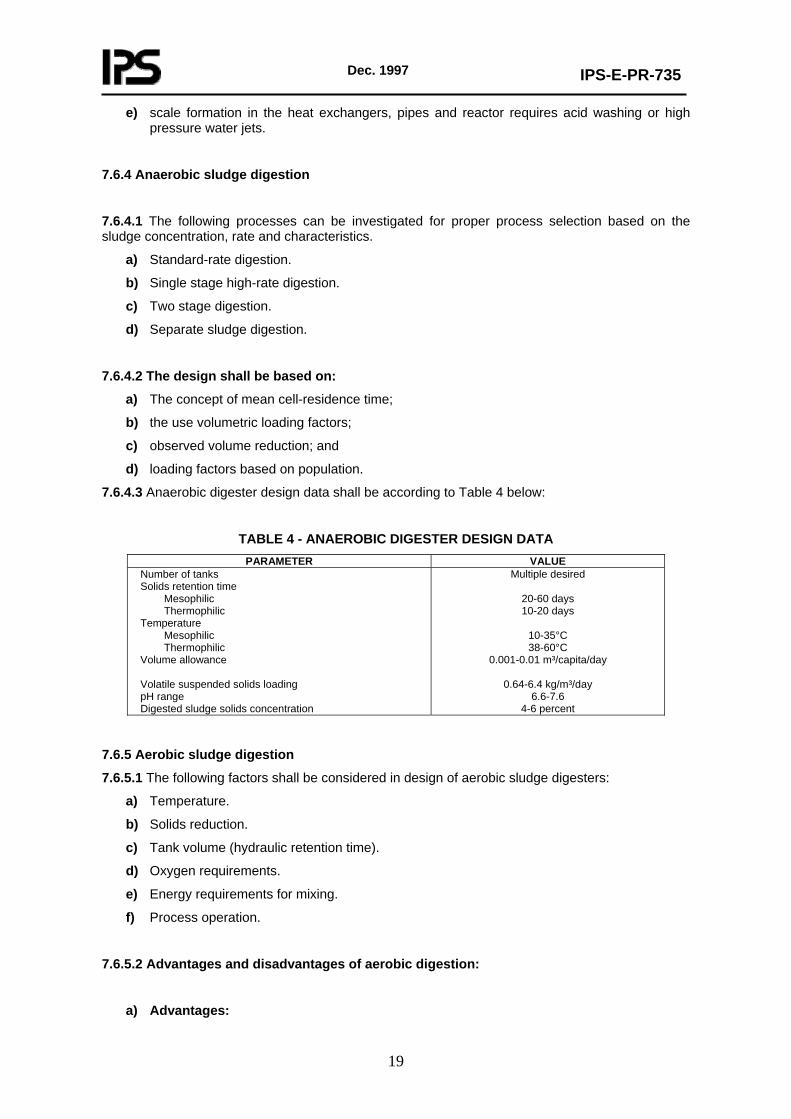
7.6.4.3 Anaerobic digester design data shall be according to Table 4 below:
TABLE 4 - ANAEROBIC DIGESTER DESIGN DATA PARAMETER VALUE
Number of tanks Solids retention time Mesophilic Thermophilic Temperature Mesophilic Thermophilic Volume allowance Volatile suspended solids loading pH range Digested sludge solids concentration
Multiple desired
20-60 days 10-20 days
10-35°C 38-60°C
0.001-0.01 m³/capita/day
0.64-6.4 kg/m³/day 6.6-7.6
4-6 percent
7.6.5 Aerobic sludge digestion
7.6.5.1 The following factors shall be considered in design of aerobic sludge digesters:
a) Temperature.
b) Solids reduction.
c) Tank volume (hydraulic retention time).
d) Oxygen requirements.
e) Energy requirements for mixing.
f) Process operation.
7.6.5.2 Advantages and disadvantages of aerobic digestion:
a) Advantages:

Dec. 1997
IPS-E-PR-735
20
- Simplicity of operation and maintenance.
- Lower capital costs.
- Lower BOD and total phosphorous in supernatant.
- Few effects from loading, pH and toxic interference.
- Insignificant odors.
- Non-explosive.
- Reduces grease and hexane solubles.
- Better sludge fertilizer.
- Shorter retention periods.
- Excellent small plant alternative.
b)Disadvantages
- Higher operating costs.
- Highly sensitive to ambient temperature.
- No useful by-products.
- Variable dewaterability.
- Lower volatile solids reduction.
- Questionable economic for larger plants.
7.6.5.3 Aerobic digester design data shall be according to Table 5 below:
TABLE 5 - AEROBIC DIGESTER DESIGN DATA PARAMETER VALUE
Number of tanks Solids retention time at 20°C - Primary sludge - Primary and activated sludge or trickling filter sludge - Waste activated sludge only - Waste activated sludge without primary settling Volume allowance Volatile suspended solids loading Minimum dissolved oxygen Oxygen requirements - Destroy cell tissue - Reduce primary sludge Diffusion aeration - Waste activated sludge only - Mixed or other sludges Mechanical aeration
Multiple desired
15-20 days 15-20 days 10-15 days 12-18 days
0.8-0.11 m³/capacity/day 0.32-2.24 kg/m³/day
1-2 mg/L
2:1 1.6:1-1.9:1
20-30m³/min/1000 m³
Over 60 m³/min/1000 m³ 20-40 kW/1000m³
7.6.6 Composting
7.6.6.1 The composting process involves the complex destruction of organic material coupled with the production of humic acid to produce a stabilized end product.
7.6.6.2 The major types of composting systems used are the aerated static pile, window, and in-vessel (enclosed mechanical) systems. Aerated static pile is preferred.
7.6.6.3 The compost mix should be at least 40 percent dry solids to ensure adequate composting.
7.6.6.4 The following important factors shall be determined/clarified for the design of composting system.

Dec. 1997
IPS-E-PR-735
21
- Type of sludge.
- Amendments and bulking agents.
- Carbon-nitrogen ratio.
- Volatile solids.
- Air requirements.
- Moisture content.
- pH.
- Temperature.
- Mixing and turning.
- Heavy metals and trace organic.
- Site constraints.
7.7 Conditioning
7.7.1 Sludge shall be conditioned to improve its dewatering characteristics if required. Based on the economical and technical evaluation of the conditions existed, a suitable conditioning method such as addition of chemicals, heat treatment, irradiation, or solvent extraction shall be used. The heat treatment process is most applicable to biological sludges that may be difficult to stabilize or condition by other means. See Article 7.6.3 above for advantages and disadvantages of heat treatment process.
7.7.2 Intimate admixing of sludge and coagulant shall be made in chemical conditioning process for proper conditioning.
The mixing must not break the floc after it has formed, and the detention should be kept to a minimum so that sludge reaches the dewatering Unit as soon after conditioning as possible.
7.8 Disinfection
7.8.1 the following methods may be used to achieve pathogen reduction beyond that attained by stabilization:
a) Pasteurization;
b) other thermal processes such as heat conditioning, heat drying, incineration, pyrolysis, or starved air combustion;
c) high pH treatment, typically with lime, at a pH higher than 12.0 for three hours;
d) long-term storage of liquid digested sludge;
e) complete composting at temperatures above 55°C and curing in a stockpile for at least 30 days;
f) addition of chlorine to stabilize and disinfect sludge;
g) disinfection with other chemicals;
h) disinfection by high-energy irradiation.
7.8.2 Storage shall be taken into consideration in land application systems to retain sludge during periods when it cannot be applied because of whether or crop considerations. Because of the potential contamination effects of the stored sludge, special attention must be devoted to the design of these lagoons with respect to limiting percolation and the development of odors.
Dec. 1997
IPS-E-PR-735
22
7.9 Dewatering
7.9.1 Application
Dewatering is a mechanical (physical) Unit operation used to reduce moisture content of sludge for one or more of the following reasons:
a) The costs for trucking sludge to the ultimate disposal site become substantially lower when sludge volume is reduced by dewatering.
b) Dewatered sludge is generally easier to handle than thickened or liquid sludge. In most cases, dewatered sludge may be shoveled, moved about with tractors fitted with buckets and blades, and transported by belt conveyors.
c) Dewatering is required normally prior or the incineration of the sludge to increase the energy content by removal of excess moisture.
d) Dewatering is required before composting to reduce the requirements for supplemental bulking agents or amendments.
e) In some cases, removal of the excess moisture may be required to render the sludge odorless and nonputrescible.
f) Sludge dewatering is required prior to landfilling in monofills to reduce leachate production at the landfill site.
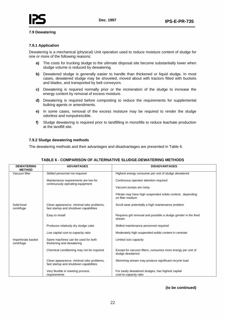
7.9.2 Sludge dewatering methods
The dewatering methods and their advantages and disadvantages are presented in Table 6.
TABLE 6 - COMPARISON OF ALTERNATIVE SLUDGE-DEWATERING METHODS DEWATERING
METHOD ADVANTAGES DISADVANTAGES
Vacuum filter Solid bowl centrifuge Imperforate basket centrifuge
Skilled personnel not required Maintenance requirements are low for continuously operating equipment Clean appearance, minimal odor problems, fast startup and shutdown capabilities Easy to install Produces relatively dry sludge cake Low capital cost-to-capacity ratio Same machines can be used for both thickening and dewatering Chemical conditioning may not be required Clean appearance, minimal odor problems, fast startup and shutdown capabilities Very flexible in meeting process requirements
Highest energy consumer per unit of sludge dewatered Continuous operator attention required Vacuum pumps are noisy Filtrate may have high suspended solids content, depending on filter medium Scroll wear potentially a high maintenance problem Requires grit removal and possible a sludge grinder in the feed stream Skilled maintenance personnel required Moderately high suspended-solids content in centrate Limited size capacity Except for vacuum filters, consumes more energy per unit of sludge dewatered Skimming stream may produce significant recycle load For easily dewatered sludges, has highest capital cost-to-capacity ratio
(to be continued)

Dec. 1997
IPS-E-PR-735
23
TABLE 6 - (continued) DEWATERING
METHOD ADVANTAGES DISADVANTAGES
Belt filter press Recessed plate filter press Sludge drying beds Sludge lagoons
Not affected by grit Excellent results for difficult sludges Low energy requirements Relatively low capital and operating costs Less complex mechanically and easier to maintain High-pressure machines are capable of producing very dry cake Minimal effort required for system shutdown Highest cake solids concentration Low suspended solids in filtrate Lowest capital cost method where land is readily available Small amount of operator attention and skill required Low energy consumption Low to no chemical consumption Less sensitive to sludge variability Higher solids content than mechanical methods Low energy consumption No chemical consumption Organic matter is further stabilized Low capital cost where land is available Least amount of skill required for operation
For most sludges, produces lowest cake solids concentration Vibration Hydraulically limited in throughput Requires sludge grinder in feed stream Very sensitive to incoming sludge feed characteristics Short media life as compared to other devices using cloth media Automatic operation generally not advised Batch operation High equipment cost high labor cost Special support structure requirements Large floor area required for equipment Skilled maintenance personnel required Additional solids due to large chemical addition require disposal Requires large area of land Requires stabilized sludge Design requires consideration of climatic effects Sludge removal is labor intensive Potential for odor and vector problems Potential for groundwater pollution More land intensive than mechanical methods Appearance may be unsightly Design requires consideration of climatic effects
The dewatering device shall be determined by the type of sludge to be dewatered, characteristics of the dewatered product, and the space available. Some sludges particularly aerobically digested sludges, are not amenable to mechanical dewatering. Selection of optimum dewatering device shall be made with conducting bench scale or pilot studies.
7.9.3 Vacuum filteration
7.9.3.1 The solids content of the feed shall be 6 to 8 percent. Higher solids contents make the sludge difficult to distribute and to condition for dewatering; lower solids contents require the use of larger than necessary vacuum filters.

Dec. 1997
IPS-E-PR-735
24
7.9.3.2 In addition to the disadvantages listed in Table 6 the following factors shall also be taken into consideration for selection of this type of dewatering equipment:
a) System complexity;
b) need for conditioning chemicals;
c) high operating and maintenance costs.
7.9.4 Centrifugation
7.9.4.1 Centrifugation process is widely used in the industry for separating liquids of different density, thickening slurries, or removing solids.
7.9.4.2 Disposal of centrate to waste water influent should be avoided.
7.9.4.3 Before final design decision making, pilot plant tests should be run.
7.9.4.4 Special consideration must be given to providing sturdy foundations and sound-proofing because of the vibration and noise that result from centrifuge operation.
7.9.5 Belt filter press
7.9.5.1 Belt filter presses are continuous-feed sludge dewatering devices that involve the application of chemical conditioning, gravity drainage, and mechanically applied pressure to dewater sludge. Belt filter presses can be applied to all types of waste water sludge.
7.9.5.2 Sludge blending facilities should be included in the system design where the sludge characteristics are likely to vary widely.
7.9.5.3 Safety considerations in design should include adequate ventilation to remove hydrogen sulfide or other gases and equipment guards to prevent loose clothing from being caught between the rollers.
7.9.6 Filter presses
7.9.6.1 In a filter press, dewatering is achieved by forcing the water from the sludge under high pressure. Advantages of this dewatering equipment include:
a) High concentrations of cake solids;
b) filterate clarity; and,
c) high solids capture.
a) Disadvantages include:
a) mechanical complexity;
b) high chemical costs;
c) high labor costs; and
d) limitations on filter cloth life.
7.9.6.2 The following filter press types are preferred:
a) Fixed-volume, recessed plate filter press.
b) Variable-volume, recessed plate filter press (diaphragm press).
7.9.6.3 The following features shall be considered in the design of a filter press facilities:
a) Adequate ventilation in the dewatering room.
b) High-pressure washing systems.

Dec. 1997
IPS-E-PR-735
25
c) An acid wash circulating system to remove calcium scale when lime is used.
d) A sludge grinder ahead of the conditioning tank.
e) Cake breakers or shredders following the filter press (particularly if the dewatered sludge is incinerated).
f) Equipment to facilitate removal and maintenance of the plates.
7.9.7 Sludge drying beds
7.9.7.1 Sludge drying beds are typically used to dewater digested sludge. After drying, the sludge is removed and either disposed of in a landfill or used as a soil conditioner.
The principal advantages of drying beds are low cost, infrequent attention required, and high solids content in the dried product.
7.9.7.2 The following types of drying beds may be used. The conventional sand drying beds is preferred:
a) Conventional sand;
b) paved (drainage or decanting);
c) artificial media; and
d) vacuum assisted.
7.9.7.3 Open beds may be used where adequate area is available and is sufficiently isolated to avoid complaints caused by occasional odors. Open sludge beds should be located at least 100 meters from dwellings to avoid odor nuisance. Covered beds with greenhouse types of enclosures shall be used where it is necessary to dewater sludge continuously throughout the year regardless of the weather and where sufficient isolation does not exist for the installation of open beds.
7.9.7.4 In cold climates, the effects of freezing and thawing shall be considered to improve the dewatering characteristics of sludge.
7.9.8 Lagoons
7.9.8.1 Drying lagoons may be used as substitute for drying beds for the dewatering of digested sludge, if permitted by Company, lagoons shall not be used for dewatering untreated sludges, limed sludges, or sludges with a high-strength supernatant because of their odor and nuisance potential.
7.9.8.2 Environmental and groundwater regulations shall be considered for application of lagoons if a groundwater aquifer used for a potable water supply underlies the lagoon site, it shall be necessary to line the lagoon.
7.9.8.3 Sludge shall be discharged to the lagoon in a manner suitable to accomplish an even distribution of sludge.
7.9.8.4 Facilities for decanting of supernatant shall be provided, and the liquid shall be recycled to the treatment facility.
7.9.8.5 A minimum of two cells shall be provided, even in very small plants, to ensure availability of storage space during cleaning, maintenance or emergency conditions.
7.10 Heat Drying
7.10.1 Sludge drying is a Unit operation that involves reducing water content by vaporization of water to the air. Drying is necessary in fertilizer manufacturing so as to permit the grinding of the sludge, to reduce its mass, and to prevent continued biological action. The moisture content of the dried sludge shall be less than 10 percent.
7.10.2 The following mechanical processes may be used for drying sludge:

Dec. 1997
IPS-E-PR-735
26
a) Flash dryers;
b) spray dryers;
c) rotary dryers;
d) multiple-hearth dryers; and
e) multiple-effect evaporation.
Sludge dryers are normally preceded by dewatering. Flash dryers are preferred in use at waste water treatment plants.
7.10.3 The heat recovered from the dried sludge should be used (if possible) to supply the energy requirements of the process.
7.10.4 Fly ash and odor control shall be considered in heat drying of sludge.
7.11 Thermal Reduction
7.11.1 General
7.11.1.1 Thermal reduction of sludge involves the total or partial conversion of organic solids to oxidized end products, primarily carbon dioxide and water, by incineration or wet-air oxidation or the partial oxidation and volatilization of organic solids by pyrolysis or starved-air combustion to end products with energy content. Thermal reduction processes are used by medium to large sized plants with limited ultimate disposal options.
7.11.1.2 The major advantages and disadvantages are:
a) Advantages:
- Maximum volume reduction, thereby lessening the disposal requirements.
- Destruction of pathogens and toxic compounds.
- Energy recovery potential.
b) Disadvantages:
- High capital and operating cost.
- Highly skilled operating and maintenance staffs are required.
- The residuals produced (air emissions and ash) may have adverse environmental effects.
- Disposal of residuals, which may be classified as hazardous wastes, may be uncertain and expensive.
7.11.2 Thermal reduction process applications
7.11.2.1 Multiple-hearth incineration
Multiple-hearth incineration is used to convert dewatered sludge cake to an inert ash. This process is normally used only in large plants or at the small plants where land for disposal of sludge is limited and at chemical treatment plants for the recalcining of lime sludges.
Feed sludge must contain more than 15 percent solids because of limitations on the maximum evaporating capacity of the furnace. Auxiliary fuel shall be provided.
In addition to dewatering, required ancillary processes shall include ash-handling systems and

Dec. 1997
IPS-E-PR-735
27
some type of wet or dry scrubber to meet air pollution requirements.
7.11.2.2 Fluidized-bed incineration
The fluidized bed incinerator commonly used for sludge incineration is a vertical, cylindrically shaped refractory. Lined steel shell that contains a sand bed and fluidized air orifices to produce and sustain combustion. The applications of fluidized-bed process is similar to multiple-hearth incineration.
7.11.2.3 Co-incineration
The major objective is to reduce the combined costs of incinerating sludge and solid wastes. The process has the advantages of producing the heat energy necessary to evaporate water from sludges, supporting the combustion of solid wastes and sludge, and providing an excess of heat for steam generation, if desired, without the use of auxiliary fossil fuels.
7.11.2.4 Wet-air oxidation
This process involves wet oxidation untreated sludge at an elevated temperature and pressure. A major disadvantage associated with this process is the high-strength recycle liquor produced. the liquors represent a considerable organic load on the treatment system.
7.11.2.5 Wet oxidation in a vertical, deep-well reactor
This process consists of discharging liquid sludge in the pressure and temperature controlled environment of a tube-andshell reactor suspended within a deep well. Advantages cited for this process are:
a) Small space requirements;
b) high removals of suspended solids and organic matter;
c) little odors or objectionable air emissions; and,
d) low energy requirements because the process is exothermic.
The principal disadvantages are that it does not have a long history of operation and maintenance, and skilled operators are required for process control.
7.12 Land Application of Sludge
7.12.1 The following steps shall be evaluated for development of a sludge land application system:
a) Characterization of sludge quantity and quality.
b) Review of pertinent federal, state and local regulations.
c) Evaluation and selection of site and disposal option.
d) Determination of process design parameters such as loading rates, land area requirements, application methods and scheduling.
7.12.2 The following factors shall be considered in evaluation of the sludge characteristics:
- Organic content (usually measured as volatile solids).
- Nutrients.
- Pathogens.
- Metals.
Dec. 1997
IPS-E-PR-735
28
- Toxic organic.
7.12.3 If regulations require, detailed sampling and analysis of sludge shall be made to identify and characterize the sludge constituents so as to determine if the sludge is suitable for land application. Maximum annual loading rates shall be prescribed as well as permissible cumulative loading rates, depending on whether the land is used for agricultural or non-agricultural purposes.
7.12.4 Sludge applied to the land surface or incorporated into the soil must be treated by a Process to Significantly Reduce Pathogens (PSRP). Sludge applied to land where crops for human consumption are grown must be treated by a Process to Further Reduce Pathogens (PFRP). Examples of PSRP stabilization process are aerobic digestion, air drying, anaerobic digestion, composting, and lime stabilization. Examples of PFRP stabilization processes are composting, heat drying, and thermophilic aerobic digestion.
7.12.5 For site selection and evaluation the following factors shall be taken into consideration:
- Land application option(s) such as application to agricultural lands, forest lands, etc.;
- topography;
- soil permeability;
- site drainage;
- depth to groundwater;
- subsurface geology;
- proximity to critical areas;
- accessibility;
- maximum sludge loading rates based on the pollutant limits set forth in regulatory guidelines or by the nutrientloading rates necessary to meet vegetation requirements.
7.12.6 Application of sludge in the liquid state is attractive and dewatering processes are not required in this case. Liquid sludge may be applied to land by vehicle or by irrigation methods.
Liquid sludge can be injected below the soil surface by using tank wagons or tank trucks with injection shanks, or it can be incorporated immediately after the surface application by using plows or discs equipped with sludge distribution manifolds and covering spoons.
7.12.7 Special attention shall be made to minimization of potential odors and vector attraction, minimization of ammonia loss due to volatilization, elimination of surface run-off, and minimum visibility leading to better public acceptance.
7.13 Chemical Fixation
7.13.1 The chemical fixation/solidification process is applied to the treatment of industrial sludge and hazardous wastes to immobilize the undesirable constituents.
7.13.2 The chemical fixation process consists of mixing untreated or treated liquid or dewatered sludge with stabilizing agents such as cement, sodium silicate, pozzolan (fine-grained silicate), and lime so as to chemically react with or encapsulate the sludge. The process may generate a product with a high pH, which inactivates the pathogenic bacteria and viruses.
8. FINAL SLUDGE AND SOLIDS CONVEYANCE, STORAGE AND DISPOSAL
8.1 General
8.1.1 For disposal of solid waste, reference shall be made to IPS-G-SF-130 unless otherwise specified in this Standard.

Dec. 1997
IPS-E-PR-735
29
8.1.2 The solids removed as sludge from preliminary and biological treatment processes shall be concentrated and stabilized by biological and thermal means and reduced in volume in preparation for final disposal if required.
8.1.3 Environmental Regulations and subsurface water pollution limitations shall be considered for final selection of disposal method.
8.2 Conveyance Methods
8.2.1 General
8.2.1.1 Sludge may be transported long distances by pipeline, truck, barge, rail or combination of these modes.
8.2.1.2 To minimize the danger of spills, odors, and dissemination of pathogens to the air, liquid sludges should be transported in closed vessels such as tank trucks, railroad tank cars, or covered tank barges.
Stabilized, dewatered sludges may be transferred in open vessels, such as dump trucks if permitted by the Company and allowed by the regulations. However, if the sludge is hauled long distances, the vessels should be covered.
8.2.2 Pipeline
8.2.2.1 In general, the energy requirements for long distance transportation of untreated sludges with a solids concentration of more than 6 percent shall be prohibitive.
8.2.2.2 Adequate flowrates in large diameter pipes shall be maintained to reduce the possibility of grit accumulation, grease build up in unlined pipes and other problems resulting from low flow conditions.
8.2.3 Truck
8.2.3.1 Trucking is the most flexible and most widely used method for transporting sludge. Either liquid or dewatered sludge may be hauled by truck to diverse destinations.
8.2.3.2 Trucking dewatered sludge is usually the most economical method for small to medium sized treatment facilities.
8.2.4 Barge
8.2.4.1 Barge transport is generally economical only for large facilities treating wastewater flows in excess of 15800 m³/h or in locations where one barge can serve several plants. Barges can also be used for carrying dewatered sludge in containers.
8.2.4.2 Barging sludge for ocean disposal shall be prohibited.
Dec. 1997
IPS-E-PR-735
30
8.2.5 Rail
8.2.5.1 Rail transportation may be used for the sludges of any consistency, but those with high solids content are transported most economically.
8.2.5. 2 The use of rail transportation for small quantities of sludges or for short distances is not justifiable economically.
8.2.6 Environmental considerations in sludge transportation
Environmental features such as air pollutant load, traffic, noise, etc. should be taken into consideration in sludge transportation. On a mass basis, the transportation mode than contributes the lowest pollutant load is piping. Next, in sequence, are barging and Unit train rail transportation. the highest pollutant load is from trucking.
8.3 Sludge Storage
8.3.1 General
Sludge that has been digested an aerobically before it is disposed of or used beneficially shall be stored.
Storage of liquid sludge can be accomplished in sludge storage basins, and storage of dewatered sludge can be done on storage pads.
8.3.2 Sludge storage and basins
8.3.2.1 If the basins are not loaded too heavily, provision of an aerobic surface layer through the growth of algae and by atmospheric reaeration shall be considered. Alternatively, surface aerators can be used to maintain aerobic conditions in the upper layers.
8.3.2.2 The number of basins to be used should be sufficient to allow each basin to be out of service for a period of about six months.
8.3.2.3 The depth of the sludge storage basin should be 3 to 5 m.
8.3.3 Sludge storage pads
8.3.3.1 Where dewatered sludge has to be stored prior to land application, sufficient storage area should be provided based on the number of consecutive days that sludge hauling could occur without applying sludge to land. Allowances also have to be made for paved access and for area to maneuver the sludge-hauling trucks, loaders, and application vehicles.
8.3.3.2 The storage pads should be constructed of concrete or bituminous concrete and designed to withstand the truck loadings and sludge piles.
8.3.3.3 Provisions for leachate and stormwater collection and disposal shall be considered.
8.4 Final Disposal
8.4.1 General
8.4.1.1 Final disposal for the sludge and solids that are not beneficially used usually involves some

Dec. 1997
IPS-E-PR-735
31
form of land disposal.Ocean disposal of sludge shall be prohibited.
8.4.1.2 As in the case of land application of sludge, the regulations for other methods of sludge disposal shall be required close attention and reviewed when planning and designing sludge disposal facilities.
8.4.2 Landfilling
8.4.2.1 If a suitable site is convenient, landfill can be used for disposal of sludge, grease, grit, and other solids. Stabilization may be required depending on state or local regulations.
8.4.2.2 Dewatering of sludge shall be required to reduce the volume to be transported and to control the generation of leachate from the landfill.
8.4.2.3 In a true sanitary landfill, the wastes shall be deposited in a designated area, compacted in place with a tractor or roller, and covered with a 30 cm layer of clean soil.
8.4.2.4 Special attention shall be made to minimization of the nuisance conditions such as odors and flies.
8.4.2.5 In selecting a land disposal site, consideration must be given to:
a) Environmentally sensitive areas such as wetlands, flood plains, recharge zones for aquifers, and habitats for endangered species;
b) run-off control to surface water;
c) groundwater protection;
d) air pollution from dust, particles, and odors;
e) disease vectors; and,
f) safety as related to toxic materials, fires, and access.
8.4.2.6 Trucks carrying wet sludge and grit should be able to reach the site without passing through heavily populated areas or business districts.
8.4.3 Lagooning
For lagooning, reference should also be made to Article 7.9.8 of this Standard.
8.4.3.1 Lagooning is economical if the treatment plant is in a remote location.
8.4.3.2 Excess liquid from the lagoon, if there is any, shall be returned to the plant for treatment.
8.4.3.3 Lagoons should be located away from the roads, highways and dwellings to minimize possible nuisance conditions and should be fenced to keep out unauthorized persons.
8.4.3.4 Subsurface drainage and percolation should be investigated to determine if the underlying groundwater will be affected.
8.4.3.5 The lagoon shall be lined, if excessive percolation is a problem or if regulations require leachate control.
8.5 Incineration
For incineration, reference should also be made to thermal reduction process applications outlined in Article 7.11.2 above.
8.5.1 Incinerators are generally limited to situations where adequate land for disposal of raw wastes is limited, or where land disposal or other procedures are impractical.
8.5.2 The chief advantage of incineration is reduction of waste containing organic matter to a relatively small volume of inert material. The chief disadvantage is the high initial cost and operating cost.

Dec. 1997
IPS-E-PR-735
32
8.5.3 Steam generation shall be considered if feasible and economically justified.
8.5.4 Air pollution regulations for smoke, fly ash, or hydrocarbon content of stack gases must be considered in the design stage.
8.5.5 Incinerator feeds should be limited to solid or semisolid paste like materials of low moisture content. Slurry type sludges, such as oil-water separator sludge and tank bottoms, can be dewatered and deoiled by centrifugation or filteration to produce a solids cake suitable for incineration.
8.5.6 Cake can be transported by belt, screw, or ribbon conveyors to a skip hoist which will elevate the cake to a charge hopper, Other solids including relatively dry spent clay, trash, rubbish, and garbage in trucks can be charged directly to the feed hopper from a truck ramp or indirectly using clam shell equipment. Liquid wastes can be burned with appropriate burners in the firebox.
8.5.7 Special attention shall be made to provide water scrubbers or cyclone separators if required by air pollution regulations.
8.5.8 A smoke monitor and alarm shall be provided.
8.5.9 Stacks shall be sufficiently elevated to disperse the gases and to avoid concentrations of contaminants, such as sulphur dioxide, at high ground levels.
8.5.10 The incinerators can be equipped with multiple or single hearth (see 7.11.2.1 of this Standard).
8.6 Ash Handling and Disposal
The ash may or may not be wetted by a water spray as it is removed. The ash can be dropped into a pit and removed by an elevating device to a hopper which is emptied into a truck when required. Ash may be used for road, fire bank, and tank foundation construction.

Dec. 1997
IPS-E-PR-735
33
APPENDICES
APPENDIX A
TABLE A.1 - SOURCES OF SOLIDS AND SLUDGE FROM A CONVENTIONAL WASTE WATER TREATMENT PLANT
UNIT OPERATION OR PROCESS
TYPES OF SOLIDS OR SLUDGE
REMARKS
Screening Grit removal Pre-aeration Primary sedimentation Biological treatment Secondary sedimentation Sludge-processing facilities
Coarse solids Grit and scum Grit and scum Primary sludge and scum Suspended solids Secondary sludge and scum Sludge, compost ,and ashes
Coarse solids are removed by mechanical and handcleaned bar screens. In small plants, screenings are often comminuted for removal in subsequent treatment Units. Scum removal facilities are often omitted in grit removal facilities. In some plants, scum removal facilities are not provided in pre-aeration tanks. If the pre-aeration tanks are not preceded by grit removal facilities, grit deposition may occur in pre-aeration tanks. Quantities of sludge and scum depend upon the nature of the collection system and whether industrial wastes are discharged to the system. Suspended solids are produced by the biological conversion of BOD. Some form of thickening may be required to concentrate the waste sludge stream from biological treatment. Provision for scum removal from secondary settling tanks is a requirement of the US Environmental Protection Agency (EPA). The characteristics of the end products depend on the characteristics of the sludge being treated and the operations and processes used. Regulations for the disposal of residuals are becoming increasingly stringent.

Dec. 1997
IPS-E-PR-735
34
APPENDIX B
TYPICAL CHARACTERISTICS OF SOLIDS AND SLUDGE
TABLE B.1 - CHARACTERISTICS OF SOLIDS AND SLUDGE PRODUCED DURING WASTE WATER TREATMENT
SOLID OR SLUDGE DESCRIPTION Screenings Grit Scum/grease Primary sludge Sludge from chemical precipitation Activated sludge Trickling-filter sludge Digested sludge (aerobic)
Screenings include all types of organic and inorganic materials large enough to be removed on bar racks. The organic content varies, depending on the nature of the system and the season of the year. Grit is usually made of the heavier inorganic solids that settle with relatively high velocities. Depending on the operating conditions, grit may also contain significant amounts of organic matter, especially fats and grease. Scum consists of the floatable materials skimmed from the surface of primary and secondary settling tanks. Scum may contain grease, vegetable and mineral oils, animal fats, waxes, soaps, food wastes, vegetable and fruit skins, hair, paper and cotton, cigarette tips, plastic materials, condoms, grit particles, and similar materials. The relative density (specific gravity) of scum is less than 1.0 and usually around 0.95. Sludge from primary settling tanks is usually gray and slimy and, in most cases, has an extremely offensive odor. Primary sludge can be readily digested under suitable conditions of operation. Sludge from chemical precipitation with metal salts is usually dark in color, though its surface may be red if it contains much iron. Lime sludge is grayish brown. The odor of chemical sludge may be objectionable, but is not as bad as primary sludge. While chemical sludge is somewhat slimy, the hydrate of iron or aluminum in it makes it gelatinous. If the sludge is left in the tank, it undergoes decomposition similar to primary sludge, but at a slower rate. Substantial quantities of gas may be given off and the sludge density increased by long residence times in storage. Activated sludge generally has a brownish, flocculant appearance. If the color is dark, the sludge may be approaching a septic condition. If the color is lighter than usual, there may have been under aeration with a tendency for the solids to settle slowly. Sludge in good condition has an inoffensive "earthy" odor. The sludge tends to become septic rapidly and then has a disagreeable odor of putrefaction. Activated sludge will digest readily alone or when mixed with primary sludge. Humus sludge from trickling filters is brownish, flocculant, and relatively inoffensive when fresh. It generally undergoes decomposition more slowly than other undigested sludges. When trickling-filter sludge contains many worms, it may become inoffensive quickly. Trickling-filter sludge digests readily. Aerobically digested sludge is brown to dark brown and has a flocculant appearance. The odor of aerobically digested sludge is not offensive; it is often characterized as musty. Well digested aerobic sludge dewaters easily on drying beds.
( to be continued)

Dec. 1997
IPS-E-PR-735
35
APPENDIX B (continued)
TABLE B.1 (continued) SOLIDS OR SLUDGE DESCRIPTION
Digested sludge (anaerobic) Composted sludge Septage
An aerobically digested sludge is dark brown to black and contains an exceptionally large quantity of gas. When thoroughly digested, it is not offensive, its odor being relatively faint and like that of hot tar, burnt rubber, or sealing wax. When drawn off onto porous beds in thin layers, the solids first are carried to the surface by the entrained gases, leaving a sheet of comparatively clear water. The water drains off rapidly and allows the solids to sink down slowly on to the bed. As the sludge dries, the gases escape, leaving a well-cracked surface with an odor resembling that of garden loam. Composted sludge is usually dark brown to black, but the color may vary if bulking agents such as recycled compost or wood chips have been used in the composting process. The odor of well-composted sludge is inoffensive and resembles that of commercial garden-type soil conditioners. Sludge from septic tanks is black. Unless the sludge is well digested by long storage, it is offensive because of the hydrogen sulfide and other gases that it gives off. The sludge can be dried on porous beds if spread out in thin layers, but objectionable odors can be expected while it is draining unless it is well-digested.
TABLE B.2 - TYPICAL CHEMICAL COMPOSITION AND PROPERTIES OF UNTREATED AND DIGESTED SLUDGE
UNTREATED PRIMARY
SLUDGE DIGESTED PRIMARY
SLUDGE ITEM
RANGE TYPICAL RANGE TYPICAL
ACTIVATED SLUDGE, RANGE
Total dry solids (TS),% Volatile solids (% of TS) Grease and fats (% of TS) Ether soluble Ether extract Protein (% of TS) Nitrogen (N, % of TS) Phosphorus (P2O5, % of TS) Potash (K2O, % of TS) Cellulose (% of TS) Iron (not as sulfide) Silica (SiO2, % of TS) pH Alkalinity (mg/L as CaCO3) Organic acids (mg/L as Hac) Energy content, Btu/b
2.0-8.0 60.80
6-30 7-35
20-30 1.5-4
0.8-2.8 0-1
8.0-15.0 2.0-4.0
15.0-20.0 5.0-8.0
500-1.500 200-2.000
10,000-12,500
5.0 65
--- --- 25 2.5 1.6 0.4
10.0 2.5 --- 6.0 600 500
11,000
6.0-12.0 30-60
5-20 ---
15-20 1.6-6.0 1.5-4.0 0.0-3.0
8.0-15.0 3.0-8.0
10.0-20.0 6.5-7.5
2,500-3,500 100-600
4,000-6,000
10.0 40
18 --- 18 3.0 2.5 1.0
10.0 4.0 --- 7.0
3,000 200
5,000
0.83-1.16 59-88
---
5-12 32-41
2.4-5.0 2.8-11.0 0.5-0.7
--- --- ---
6.5-8.0 580-1,100
1,100-1,700 8,000-10,000
Note:
Btu/lb × 2.3241 = kJ/kg
(to be continued)

Dec. 1997
IPS-E-PR-735
36
APPENDIX B (continued)
TABLE B.3 - TYPICAL METAL CONTENT IN WASTE WATER SLUDGE DRY SLUDGE, mg/kg
Metal Range Median Arsenic Cadmium Chromium Cobalt Copper Iron Lead Manganese Mercury Molybdenum Nickel Selenium Tin Zinc
1.1-230 1-3,410
10-99,000 11.3-2,490 84-17,000
1,000-154,000 13-26,000 32-9,870 0.6-56
0.1-214 2-5,300 1.7-17.2 2.6-329
101-49,000
10 10
500 30
800 17,000
500 260 6 4
80 5
14 1,700
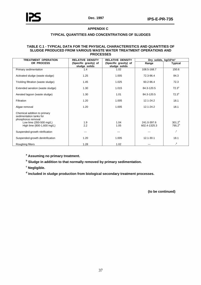
Dec. 1997
IPS-E-PR-735
37
APPENDIX C
TYPICAL QUANTITIES AND CONCENTRATIONS OF SLUDGES
TABLE C.1 - TYPICAL DATA FOR THE PHYSICAL CHARACTERISTICS AND QUANTITIES OF SLUDGE PRODUCED FROM VARIOUS WASTE WATER TREATMENT OPERATIONS AND
PROCESSES Dry solids, kg/10³m³ TREATMENT OPERATION
OR PROCESS RELATIVE DENSITY (Specific gravity) of
sludge solids
RELATIVE DENSITY (Specific gravity) of
sludge solids Range Typical
Primary sedimentation Activated sludge (waste sludge) Trickling filtration (waste sludge) Extended aeration (waste sludge) Aerated lagoon (waste sludge) Filtration Algae removal Chemical addition to primary sedimentation tanks for phosphorus removal Low lime (350-500 mg/L) High lime (800-1,600 mg/L) Suspended-growth nitrification Suspended-growth denitrification Roughing filters
1.4
1.25
1.45
1.30
1.30
1.20
1.20
1.9 2.2
---
1.20
1.28
1.02
1.005
1.025
1.015
1.01
1.005
1.005
1.04 1.05
---
1.005
1.02
108.5-168.7
72.3-96.4
60.2-96.4
84.3-120.5
84.3-120.5
12.1-24.2
12.1-24.2
241.0-397.6 602.4-1325.3
---
12.1-30.1
---
150.6
84.3
72.3
72.3a
72.3a
18.1
18.1
301.2b 795.2b
-c
18.1
-d
a Assuming no primary treatment. b Sludge in addition to that normally removed by primary sedimentation. c Negligible. d Included in sludge production from biological secondary treatment processes.
(to be continued)

Dec. 1997
IPS-E-PR-735
38
APPENDIX C (continued)
TABLE C.2 - EXPECTED SLUDGE CONCENTRATIONS FROM VARIOUS TREATMENT OPERATIONS AND PROCESSES
SLUDGE SOLIDS CONCENTRATION, % DRY
SOLIDS
OPERATION OR PROCESS APPLICATION
Range Typical Primary settling tank Primary sludge Primary sludge to a cyclone Primary and waste activated sludge Primary sludge and trickling-filter humus Primary sludge with iron addition for phosphorus removal Primary sludge with low lime addition for phosphorus removal Primary sludge with high lime addition for phosphorus removal Scum Secondary settling tank Waste activated sludge With primary settling Without primary settling High-purity oxygen activated sludge With primary settling Without primary settling Trickling-filter humus sludge Rotating biological contractor waste sludge Gravity thickener Primary sludge only Primary and waste activated sludge Primary sludge and trickling-filter humus Dissolved-air flotation thickener Waste activated sludge only With chemical addition Without chemical addition Centrifuge thickener Waste activated sludge only Gravity belt thickener Waste activated sludge only with chemical addition Anaerobic digester Primary sludge only Primary and waste activated sludge Primary sludge and trickling-filter humus Aerobic digester Primary sludge only Primary and waste activated sludge Waste activated sludge only
4.0-10.0 0.5-3.0 3.0-8.0
4.0-10.0 0.5-3.0 2.0-8.0
4.0-16.0 3.0-10.0
0.5-1.5 0.8-2.5
1.3-3.0 1.4-4.0 1.0-3.0 1.0-3.0
5.0-10.0 2.0-8.0 4.0-9.0
4.0-6.0 3.0-5.0
4.0-8.0
3.0-6.0
5.0-10.0 2.5-7.0 3.0-8.0
2.5-7.0 1.5-4.0 0.8-2.5
5.0 1.5 4.0 5.0 2.0 4.0
10.0 5.0
0.8 1.3
2.0 2.5 1.5 1.5
8.0 4.0 5.0
5.0 4.0
5.0
5.0
7.0 3.5 4.0
3.5 2.5 1.3