
Engineering failure analysis and design of support system ...
24
RESEARCH Open Access Engineering failure analysis and design of support system for ancient Egyptian monuments in Valley of the Kings, Luxor, Egypt Sayed Hemeda 1,2 Abstract Background: The paper represents the first comprehensive experimental and numerical study for engineering failure analysis and appropriate design for the permanent mechanical support system for the tomb of the Sons of Ramesses II (KV5). It is, in fact, one of the largest rock cut tombs ever found in Egypt. During the late 18th Dynasty and throughout the19th, the tombs are usually located further down the Valley some distance from the rock walls. The builders often quarried through talus slopes, such as in the case of the tomb of Sons of Ramses II. It is clear that the tomb of sons of Ramsses II is much more susceptible to surcharge geostatic loading from the overburden rock strata, rock bursting, and structural damage of support pillars and walls induced to the water and past/recent flash floods impacts caused by heavy rain in the Valley. Since some of this tomb also makes contact with the underlying shale layers, that have the potential for swelling and shrinkage under changing moisture conditions. Expansive damages to these underground structures have been widely noticed in the Valley of the Kings. This tomb tends to be the worst preserved tomb in the Valley of the Kings. The Esna shale in the valley is particularly weak and unstable. It not only posed problems to the ancient quarryman, but to the modern conservator as well. When the shale comes into contact with moisture, it expands and can literally tear a hill side apart. Results: The main adjectives of the geoenvironmental and geotechnical analyses carried out in the present study are to investigate the static stability, safety margins and engineering failure of the tomb of Sons of Ramsses II (KV5) under their present conditions, against unfavorable environmental (i.e. extensive weathering due to water and flash floods impact in the past and present), utter lack of preservation, geostatic overloading of structural rock support pillars, geotechnical and extreme seismic conditions. Also to design an appropriate geotechnical support system, according to the engineering rock mass classification, in particularly the rock mass rating RMR and quality rock tunneling index Q-system. (Continued on next page) Correspondence: [email protected] 1 Conservation Department, Faculty of Archaeology, Cairo University, Giza, Egypt 2 Aristotle University of Thessaloniki, Thessaloniki, Greece Geoenvironmental Disasters © The Author(s). 2018 Open Access This article is distributed under the terms of the Creative Commons Attribution 4.0 International License (http://creativecommons.org/licenses/by/4.0/), which permits unrestricted use, distribution, and reproduction in any medium, provided you give appropriate credit to the original author(s) and the source, provide a link to the Creative Commons license, and indicate if changes were made. Hemeda Geoenvironmental Disasters (2018) 5:12 https://doi.org/10.1186/s40677-018-0100-x
Transcript of Engineering failure analysis and design of support system ...

RESEARCH Open Access
Engineering failure analysis and design ofsupport system for ancient Egyptianmonuments in Valley of the Kings, Luxor,EgyptSayed Hemeda1,2
Abstract
Background: The paper represents the first comprehensive experimental and numerical study for engineering failureanalysis and appropriate design for the permanent mechanical support system for the tomb of the Sons of Ramesses II(KV5). It is, in fact, one of the largest rock cut tombs ever found in Egypt. During the late 18th Dynasty and throughoutthe19th, the tombs are usually located further down the Valley some distance from the rock walls. The builders oftenquarried through talus slopes, such as in the case of the tomb of Sons of Ramses II. It is clear that the tomb of sons ofRamsses II is much more susceptible to surcharge geostatic loading from the overburden rock strata, rock bursting, andstructural damage of support pillars and walls induced to the water and past/recent flash floods impacts caused by heavyrain in the Valley. Since some of this tomb also makes contact with the underlying shale layers, that have the potential forswelling and shrinkage under changing moisture conditions. Expansive damages to these underground structures havebeen widely noticed in the Valley of the Kings. This tomb tends to be the worst preserved tomb in the Valley of theKings. The Esna shale in the valley is particularly weak and unstable. It not only posed problems to the ancientquarryman, but to the modern conservator as well. When the shale comes into contact with moisture, it expands andcan literally tear a hill side apart.
Results: The main adjectives of the geoenvironmental and geotechnical analyses carried out in the present study areto investigate the static stability, safety margins and engineering failure of the tomb of Sons of Ramsses II (KV5) undertheir present conditions, against unfavorable environmental (i.e. extensive weathering due to water and flash floodsimpact in the past and present), utter lack of preservation, geostatic overloading of structural rock support pillars,geotechnical and extreme seismic conditions. Also to design an appropriate geotechnical support system, accordingto the engineering rock mass classification, in particularly the rock mass rating RMR and quality rock tunneling indexQ-system.
(Continued on next page)
Correspondence: [email protected] Department, Faculty of Archaeology, Cairo University, Giza, Egypt2Aristotle University of Thessaloniki, Thessaloniki, Greece
Geoenvironmental Disasters
© The Author(s). 2018 Open Access This article is distributed under the terms of the Creative Commons Attribution 4.0International License (http://creativecommons.org/licenses/by/4.0/), which permits unrestricted use, distribution, andreproduction in any medium, provided you give appropriate credit to the original author(s) and the source, provide a link tothe Creative Commons license, and indicate if changes were made.
Hemeda Geoenvironmental Disasters (2018) 5:12 https://doi.org/10.1186/s40677-018-0100-x

(Continued from previous page)
Conclusions: The engineering analysis had been carried out through the following four steps: 1-Evaluation of thesurrounding rocks (marl limestone) by experimental investigation and the Roclab program to obtain Hoek BrownClassification criterion, Mohr- Coulomb fit and the rock mass parameters in particular the global strength anddeformation modulus. 2- Qualitative and quantitative estimations of relevant factors affecting the stability of the tombin particularly the overburden or geostatic and dynamic loading. 3- 2D and 3D integrated geotechnical modeling ofthe tomb environment for stress, displacement analyses and determination of volumetric strains and plastic pointsusing advanced codes and programs like Examine 2D and PLAXIS 3D. The numerical analysis results indicated that thesafety factor of the rock pillar structural supports is 1.37 and the overstress state is 1.28 MPa. 4-Remedial and retrofittingpolicies and techniques, static monitoring and control systems which are necessary for the strengthening and stabilityenhancement of the tomb, where the rock mass classification indicated the rock mass where the KV5 is excavated ispoor rock, with RMR 39 and Q value 1.87.Based on the underground engineering stable equilibrium theory and rock mass classification, three support structuretechniques are provided and detailed illustrated with the case of KV5 in this study.
Keywords: Geotechnical problems, Rock character, Support structure, Tomb of the sons of Ramses II, Valley of the kings
BackgroundAmongst the many monument types which exist all overthe world, underground sites such as caves, tombs,crypts and catacombs can be singled out as a categorywhich has its own particular set of “adversaries”. Theselocations are to a certain extent “protected” by the earthor rock surrounding them; this is especially so whenthese sites remain sealed, or has only one small or par-tially blocked opening to the exterior. However, when aninterred site is discovered and uncovered, its microcli-mate is disturbed and fluctuations in internal conditionscommence. These variations become accentuated if theprotective covering is removed either during excavationor later to create a new wider access to the site. This in-stability eventually leads to deterioration of the site andin particularly any decorations or paintings it may con-tain. Further deterioration is caused by other unrelatedsources such as water seepage and occasionally alsoflooding like the tomb KV5 which under investigation,salt damage and the accumulation of dust, debris andother contaminants. The problems are common to allpainted underground and semi-buried sites in the valleyof kings at Luxor, Egypt.It is important to say that in geological engineering,
including in underground rock engineering and rockmechanics, lots of the hazards sources arise from geo-technical uncertainty or error. The sources of uncer-tainty can be classified as: (1) inalienable spatial andfleeting fluctuation; (2) estimation and observing blun-ders; (3) demonstrating vulnerability; (4) load andstresses vulnerability (Brown 2012). In geotechnical en-gineering it is perceived that stone disfigurement is im-perative in deciding the advancement of characteristicstructures and structural highlights. Numerous investi-gations and field work has been done to comprehendthe fragile break procedures and systems. Quite a bit of
this focused on the research center testing and the esti-mation of fragile crack limits (Deere and Varde 1990).The Geotechnical instability problems and degradation
phenomena of rock cut tombs in the Valley of the Kings(KV) is likely to be dominated by gravity fall and slidingon structural features, also other factors such as exces-sively high rock stress, creep effect, poor geotechnicalproperties of rock structures, weathering and /or swell-ing rock and flash floods caused by heavy rains in theValley, vibrations and dynamic loading as well as utterlack of preservation become important and can be evalu-ated by means of a classification of rock quality. TheEsna shale in the valley is particularly weak and unstable.It not only posed problems to the ancient quarryman,but to the modern conservator as well. When the shalecomes into contact with moisture, it expands and canliterally tear a hill side apart.The tomb was robbed in antiquity. Since then, it has
been hit by at least eleven flash floods caused by heavyrains in the Valley. These have completely filled thetomb with debris and seriously damaged its comprehen-sively decorated walls. From about 1960 to 1990, tourbuses parked above the tomb; their vibrations causedserious damage to parts of the tomb near the roadway,as did a leaking sewer line installed over the entrancewhen the Valley of the Kings rest house was built.In October and November of 1994, two flood events
occurred in the Valley of Kings, sending a warning to allheritage managers. In both cases, a local desert rain-storm occurred in the vicinity of the Valley of Kings.Storm-water runoff and sediment entered the tomb ofSons of Ramsses II and other many o tombs and causederosion of gully floors.Current farming procedures have additionally added to
the topographical traits of the Nile Valley bowl. Today,ground water levels have ascended here, and debilitate
Hemeda Geoenvironmental Disasters (2018) 5:12 Page 2 of 24

low lying shaft tombs and the morgue sanctuaries on theedge of the development, and in addition the outstand-ing Luxor and Karnak sanctuaries on the east bank.The tomb of Sons of Ramsses II (KV5) is located at the
middle of the Valley of the Kings, East Valley, Thebes WestBank at Thebes (Reeves and Wilkinson 1966). The ThebanMapping Project’s excavations have shown that KV 5 con-tains not just the six rooms first seen by Burton in 1825,but over 150 corridors and chambers dug deep into thehillside, as shown in Fig. 1.KV 5 itself is the largest rock cut tomb in the Valley of
the Kings; pillared chamber 3 is the largest chamber of anytomb in the Valley of the Kings. Chambers 1 to 6 had beendiscovered in 1825 by James Burton, all other had been
discovered by Theban Mapping Project in 1995 (Clayton1995, Weeks 1992, 1994 and 1995), as shown in Fig. 2.There is an adjustment in the tomb’s essential pivot
after chamber 3; a few chambers lie underneath differentchambers; two hallways reach out toward the northwestunderneath the passageway and the street before thetomb. Pillared chamber 3 has more columns (sixteen)than some other chamber in the Valley of the Kings. Themeasured dimensions of the KV5 are maximum heightof 2.85 m, width of 0.61~ 15.43 m, total length of443.2 m; total area of 1266.47 m2 and total volume of2154.82 m3. Pillars Conditions are excavated, decorationdamaged, damaged structurally (Weeks 1998, 2000 and2006), as shown in Fig. 3.
Fig. 1 Aerial photograph indicates the east (main) Valley of the Kings (KV) at Luxor Egypt. Modified after Google earth map. The tomb of Sonsof Ramsses II (KV5) is located at the middle of the Valley of the Kings, East Valley, Thebes West Bank at Thebes. The Theban Mapping Project’sexcavations have shown that KV 5 contains not just the six rooms first seen by Burton in 1825, but over 150 corridors and chambers dug deepinto the hillside
Fig. 2 Location of the tomb of Sons of Ramsses II (KV5) at the east (main) Valley of the Kings (KV), Luxor Egypt. KV 5 itself is the largest rock cuttomb in the Valley of the Kings; pillared chamber 3 is the largest chamber of any tomb in the Valley of the Kings. Chambers 1 to 6 had beendiscovered in 1825 by James Burton, all other had been discovered by Theban Mapping Project in 1995 (Clayton 1995)
Hemeda Geoenvironmental Disasters (2018) 5:12 Page 3 of 24

Methods and experimentalThe rock mass petrography and mechanical strengthwhere the tomb of sons of Ramses II is excavated has beenanalyzed by experimental investigations, which includeXRD, XRF and DTA-TGA analysis and thin section exam-ination under polarized light microscope. A comprehen-sive program for petro physical and mechanical testinginclude the uniaxial compression test and ultra-sonic wavevelocity through the materials (PUNDT) has been estab-lished. The RocLab program has been utilized to calculatethe Hoek-Brown Classification and criterion also tocalculate the Mohr-Coulomb fits and rock strengthparameters in particularly the deformation modulus(RocLab 1.0. 2018). Underground structures safety ana-lysis is performed using the finite element (FE) method.The research presents a comprehensive study for the rockcut tombs safety analysis. The safety analysis includes notonly a failure analysis but the effect of weathering, inparticular the materials wear on the differential settlementhave been investigated. The commercial FE package Exam-ine 2D is used for conducting stress, as well as settlementanalysis. Examine 2D is a finite element program developedfor numerical analysis of geotechnical and undergroundand subterranean structures (Examine 2D 2018).The deformation of these rock cut tombs has been
computed as realistically as possible, utilizing an advancednonlinear elasto-plastic material model needs to be utilizedin PLAXIS 3D which is capable of utilizing such advancedmaterial models (PLAXIS 3D Software 2018). 3D Plasticmodel is used for deformation and consolidation analysis inthis research. The consolidation analysis is performed usingPLAXIS 3D. Also in this research, we attempt to construct
and analyze a three-dimensional (3D) finite elementmodel (FEM) of the pillared chamber 3 with its structur-ally damaged sixteen rock pillars and the large northernhall which are excavated in this poor and extensivelyweathered marl limestone deposit (member 1), using thePLAXIS 3D code.The Rock Mass Classification calculations are utilized
for the general assessment of the rock mass where theKV5 is excavated. The results of the rock mas rating(RMR) and Q-system values were utilized to design anappropriate support system.
The geology of Gebel El-Gurnah, LuxorGebel El-Gurnah is located some 4 km to the west ofthe River Nile, opposite to Luxor. The main exposedrock units in Gebel El-Gurnah are the Esna Shale andThebes limestone formations. The tombs of the kingswere excavated in the Thebes formations at northernside of Gebel El-Gurnah and the tombs of the queenswere excavated at the southern side (Litherland 2013,Dunn 2014, Wüst and McLane 2000).The main exposed rocks in Gebel El-Gurnah are the
Esna Shale (late Paleocene- Early Eocene) and the con-formatably overlying Thebes formation (Early Eocene).
Esna ShaleThe lower 25 m of this formation is less calcareous, usu-ally is green dark grey, and sometimes nearly block. Theupper shale is whitish grey and greenish, more compactand carries more gypsum vienlets. The iron oxides varyin color. Brownish red and yellow hematitic and limon-itic concretions are present; the ferruginous concretions
Fig. 3 The present layout and plan of the tomb of Sons of Ramsses II (KV5). The Measurements of the KV5 are: Maximum height: 2.85 m.Minimum width: 0.61 m. Maximum width: 15.43 m. Total length: 443.2 m. Total area: 1266.47 m2. Total volume: 2154.82 m3. Pillars Conditions areexcavated, cutting finished, decorated, decoration damaged, damaged structurally
Hemeda Geoenvironmental Disasters (2018) 5:12 Page 4 of 24

are characteristic feature foe the whole formation. Thegypsum vienlets run mostly parallel to the beddingplanes (Wüst and McLane 2000), as shown in Fig. 4a.
Thebes formationThe Thebes formation exposed in the valley of kingscould be subdivided into three members (from base totop) Hamadat, Beida and Al-Geer members however, theThebes formation conformably overlying the Esna Shale.The lower member Hamadat is white, chalky induratedlimestone with flint concretions, the middle memberBeida is made up indurated, thick bedded, nodular lime-stone with flint bands extending parallel to the beddingplanes, the uppermost member Al-Geer consists mainlyof white limestone, (Aubry et al. 2008 and Siliotti 1997),as shown in Figs. 4b and 5.There are many faults in the SW corner of the Valley of
the Kings; it is very composite in its nature. Number offaults are cutting the Eocene limestone Formations. Typic-ally, those issue dividers bring differentiated throughoutsliding, and veins about crystalline calcite have developedin the interceding spaces. The calcite may be stringy Fur-thermore structures overstepping bundles, which providefor the course What’s more sense from claiming slip.Ordinary faults, demonstrating level development for
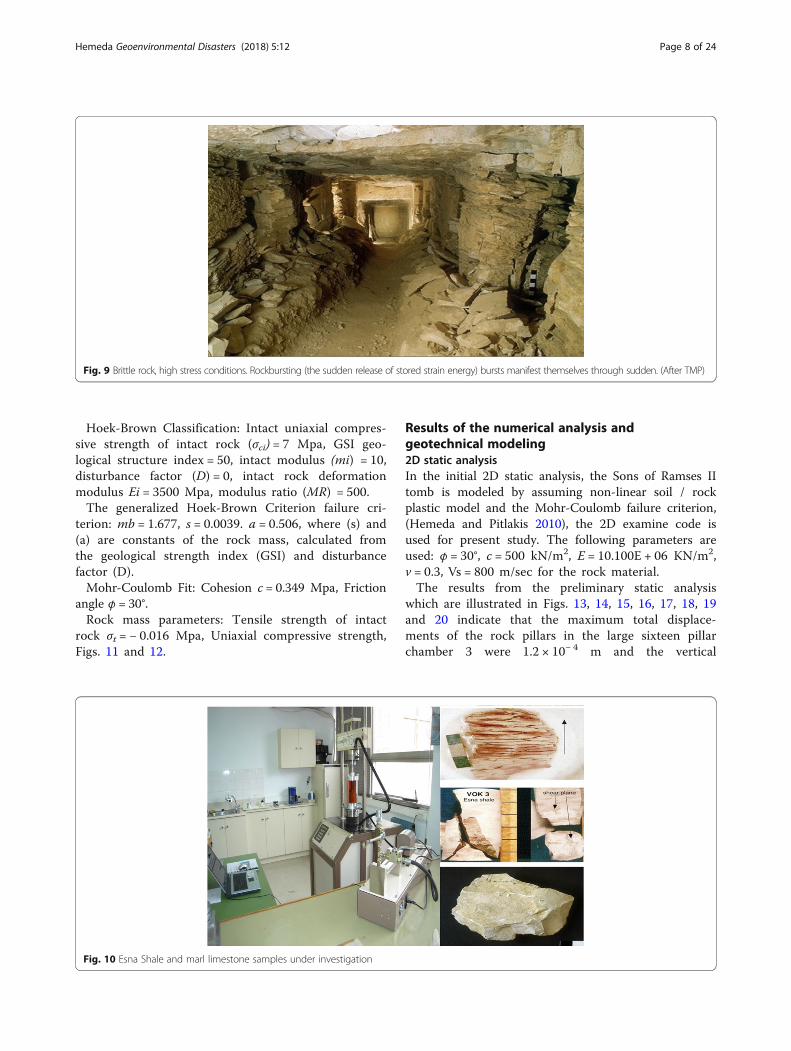
An NE-SW direction, are abundant. However, one sub-stantial fault, on the Nw side of the valley, may be dom-inantly strike-slip (and left-lateral), while others need aidoblique-slip (left-normal, alternately right-normal). Des-pite those five faults that required been measured arenot enough will a chance to be statistically significant,they are commonly perfect as shown in Figs. 6 and 7.Figures 8 and 9 present the state of preservation of theKV5 and the geological and geotechnical induced rock-mass stability problems. Where the brittle rock, high
stress conditions lead to rockbursting (the sudden re-lease of stored strain energy) bursts manifest themselvesthrough sudden.
Results of the experimental investigationGeotechnical properties of intact rock specimens anddiscontinuitiesTwenty-three cylindrical rock specimens have been pre-pared from the surrounding rock and the supporting pil-lars to delineate the physical and mechanical properties.Specific gravity, unit weight, water absorption, porosityand degree of saturation are the physical aspects deter-mined. While, the mechanical characterization includedthe determination of the uniaxial compressive strength,elastic static modulus of elasticity and Brazilian splittingtensile strength, as well as the Non-Destructive UltrasonicPulse Testing to the wave velocity through the brick speci-mens, the dynamic Young’s modulus and shear modulus.All the soil/rock testing referring to the ASTM.Thin-sections prepared on the limestone samples where
the KV5 is excavated, refers that the limestone isfine-grained calcite, embedded in a micritic matrix rich inamorphous silica, fossils like Foraminifera and large grainsof quartz.The XRD analysis indicated that the major contents of
Esna shale are quartz (SiO2) and Montmorillonite (Na0.2Ca0.1 Al2 Si4O10 (OH)2. (H2O) 10, the minor contents in-clude the Kaolinite and Illite with Calcite traces. The bulkunit weight of the Esna shale is 1.79 to 1.86 g/cm3, andthe uniaxial compressive strength is 4.22 to 4.43 kg/cm2.Petro-physical properties: Physical measurements re-
ferred that the unit weight (γ) of marl limestone of KV5is between 20 and 21 kN/m3, water absorptions (Wa)were between 10 and 12% and the apparent porosity (n)ranged from 14 to 19%.
a b
Fig. 4 a Esna Shale and b Marl Limestone (Member 1), Gebel El-Gurnah. The main exposed rocks in Gebel El-Gurnah are the Esna Shale (latePaleocene- Early Eocene) and the conformatably overlying Thebes formation (Early Eocene)
Hemeda Geoenvironmental Disasters (2018) 5:12 Page 5 of 24

Fig. 5 Geological setting of the Valley of the Kings, Luxor, Egypt. (Geological Egyptian Authority). The Thebes formation exposed in the valley ofkings could be subdivided into three members (from base to top) Hamadat, Beida and Al-Geer members however, the Thebes formationconformably overlying the Esna Shale. The lower member Hamadat is white, chalky indurated limestone with flint concretions, the middlemember Beida is made up indurated, thick bedded, nodular limestone with flint bands extending parallel to the bedding planes, the uppermostmember Al-Geer consists mainly of white limestone
Fig. 6 Thebes Formations, Valley of the Kings, Luxor, Egypt. Gebel El-Gurnah is located some 4 km to the west of the River Nile, opposite toLuxor. The main exposed rock units in Gebel El-Gurnah are the Esna Shale and Thebes limestone formations. The tombs of the kings wereexcavated in the Thebes formations at northern side of Gebel El-Gurnah and the tombs of the queens were excavated at the southern side
Hemeda Geoenvironmental Disasters (2018) 5:12 Page 6 of 24

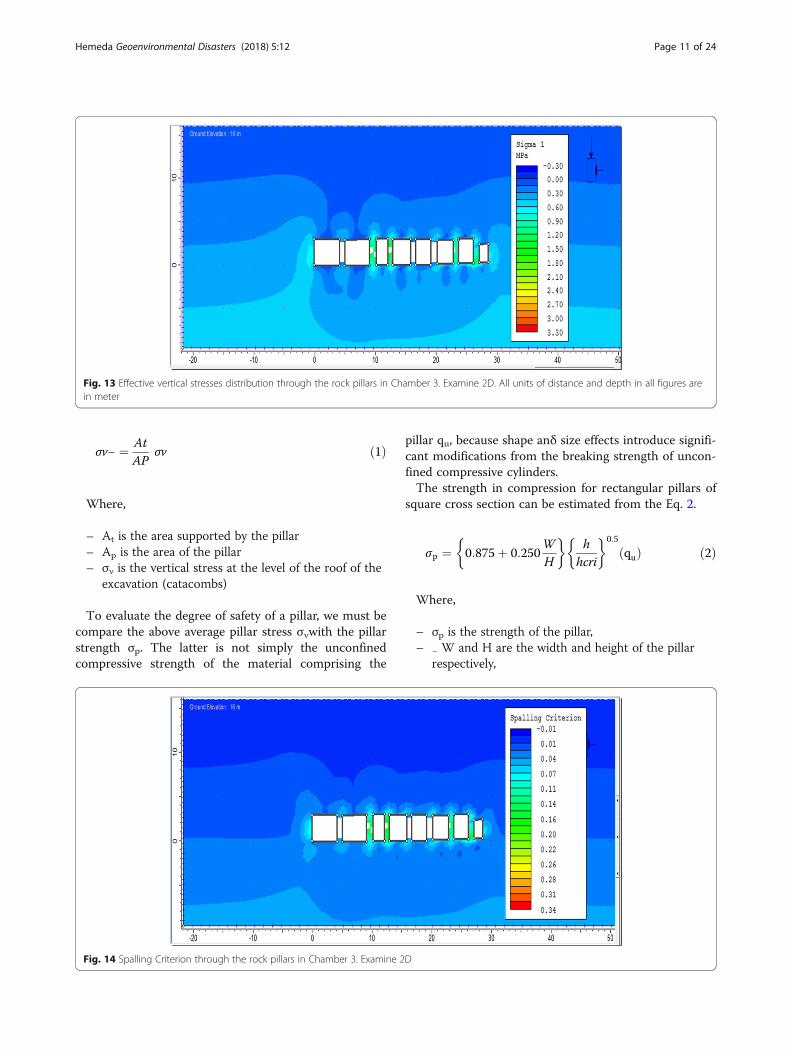
Shear Wave Velocities (Vs): Shear wave velocities oflimestone samples were measured by PUNDT (ASTM597, ASTM D 2845–83). They varied from 0.7 to1.0 km/s (with an average of 1 km/s for an orientationperpendicular on the bedding plane.Uniaxial Compression Test: The compressive strength
(σc) for the sidewalls is between 6 and 7 MPa, while the(σc) for the supporting rock pillars is 1 MPa because ofthe impact of the past and recent flash floods.
The static Young’s modulus (E) = 10 GPa, PoissonRatio (ν) = 0.28–0.30, Fig. 10 shows the test set and theresults are summarized in Tables 1, 2, 3 and 4.
Analysis of rock mass strength using RocLab programRocLab is a software program for determining rock massstrength parameters, based on the latest version of thegeneralized Hoek-Brown failure criterion.
Fig. 7 Rock structures such as joints, bedding’s characters of the Valley of the Kings (KV)
Fig. 8 Extensive structural damage in KV5. Engineering failure of the structural pillars, sidewalls and Ceiling of the Corridors and Chambers in the KV5(http://www.thebanmappingproject.com/). Permission was granted by Weeks, K.R. © Theban Mapping Project 2006 to reuse this figure
Hemeda Geoenvironmental Disasters (2018) 5:12 Page 7 of 24
Hoek-Brown Classification: Intact uniaxial compres-sive strength of intact rock (σci) = 7 Mpa, GSI geo-logical structure index = 50, intact modulus (mi) = 10,disturbance factor (D) = 0, intact rock deformationmodulus Ei = 3500 Mpa, modulus ratio (MR) = 500.The generalized Hoek-Brown Criterion failure cri-
terion: mb = 1.677, s = 0.0039. a = 0.506, where (s) and(a) are constants of the rock mass, calculated fromthe geological strength index (GSI) and disturbancefactor (D).Mohr-Coulomb Fit: Cohesion c = 0.349 Mpa, Friction
angle φ = 30°.Rock mass parameters: Tensile strength of intact
rock σt = − 0.016 Mpa, Uniaxial compressive strength,Figs. 11 and 12.
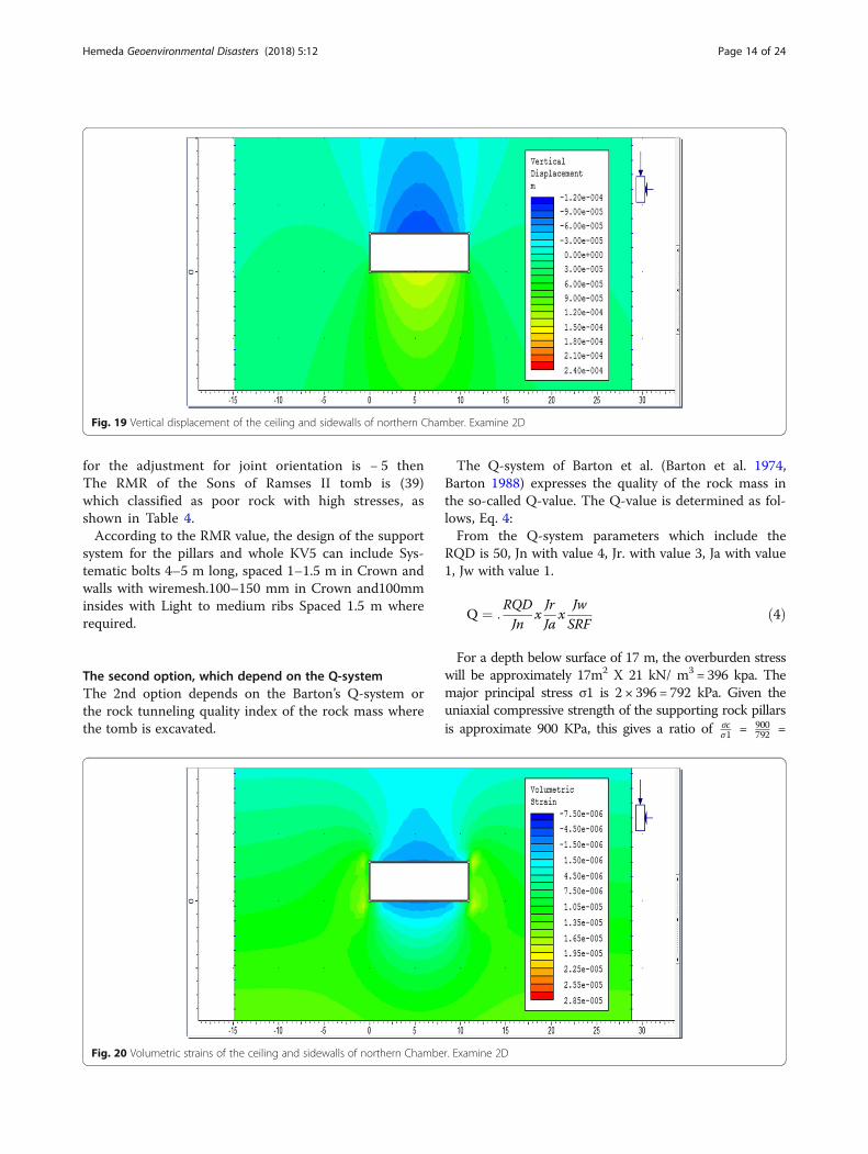
Results of the numerical analysis andgeotechnical modeling2D static analysisIn the initial 2D static analysis, the Sons of Ramses IItomb is modeled by assuming non-linear soil / rockplastic model and the Mohr-Coulomb failure criterion,(Hemeda and Pitlakis 2010), the 2D examine code isused for present study. The following parameters areused: φ = 30°, c = 500 kN/m2, E = 10.100E + 06 KN/m2,ν = 0.3, Vs = 800 m/sec for the rock material.The results from the preliminary static analysis
which are illustrated in Figs. 13, 14, 15, 16, 17, 18, 19and 20 indicate that the maximum total displace-ments of the rock pillars in the large sixteen pillarchamber 3 were 1.2 × 10− 4 m and the vertical
Fig. 9 Brittle rock, high stress conditions. Rockbursting (the sudden release of stored strain energy) bursts manifest themselves through sudden. (After TMP)
Fig. 10 Esna Shale and marl limestone samples under investigation
Hemeda Geoenvironmental Disasters (2018) 5:12 Page 8 of 24

displacements were small (of the order of millimeters1.5 X10− 4 m), Horizontal displacement 1.25 × 10− 5 m,the maximum volumetric strain is 3.5 × 10− 5 m, andthe spalling criterion is 0.22. While the maximumground vertical displacements on the roof of the largewestern two halls were large 4.5 × 10− 5 m and thevolumetric strain is 7 × 10⁻⁶.The rock pillars in the sixteen pillars largest hall
(pillared chamber 3) are under relatively high com-pression stresses. The calculated effective peak prin-cipal compressive stresses on supporting rock pillarsare about 900 kPa. The maximum shear stress is0.15 MPa, and the maximum shear strain is 1.3 ×10− 5.For the large northern hall, The calculated effective
peak principal compressive stresses is about 600 kPabut the maximum vertical displacement on the roof istoo large 1.2 × 10− 4 m and the maximum volumetricstrain is 4.5 × 10− 6, the results of the mathematicalmodeling are represented in Figs. 13, 14, 15, 16, 17,18, 19 and 20. Also the maximum vertical stress onthe roofs and sidewall of Chamber 1 and Chamber 2reached 350 KPa, and the maximum vertical displace-ment reached 4.5 × 10− 5 m, see Fig. 15, 16, 17, 18, 19and 20.
3D static analysisThe low rock strength where the KV5 is excavated af-fects seriously the safety of the tomb both under staticand seismic loading conditions. The PLAXIS 3D wasused for the 3-D numerical analysis of the central main
Chamber with its sixteen supporting structural rockpillars.A three-dimensional (3D) numerical model for the pil-
lared chamber 3 (the largest chamber in Valley of theKings (with its sixteen supporting rock pillars) and thelarge northern hall which are excavated in marl lime-stone deposit are constructed. he goal of the 3D exami-nations is to assess the pressure state in the columnsconsidering the 3D geometry. The 3D impacts issue isconsidered on a fundamental designing methodology inthe consequent areas. The different reenactmentsdepicted thus are directed utilizing the PLAXIS 3D code(PLAXIS 3D).The results from the 3D static analysis which repre-
sented in Figs. 21, 22, 23 and 24 indicate that, the rockpillars in chamber 3 are under relatively high compres-sion stresses. The calculated peak effective principalvertical compressive stresses on supporting rock pillarsis 827.58 kN/m2, the horizontal effective mean stresses588.91 kN/m2, the total displacement of the pillars210.01 × 10− 6 m, the vertical displacement 208.36 × 10− 6 m,the horizontal displacement 32.94 × 10− 6 m, the vertical in-cremental displacement 11.29 × 10− 6 m, and the volumetricstrain 3.62 × 10− 3%.For the large northern chamber, the extreme effective
mean stresses is 567.73 kN/m2, the total displace-ment 475.95 × 10− 6 m, the vertical displacement475.59 × 10− 6 m, the volumetric strain 12.42 × 10− 3%,the extreme volumetric strain incremental 1.38 × 10− 3%,and the horizontal displacement 53.60 × 10− 6 m,Figs. 24, 25, 26, 27, 28 and 29. Also the maximumvertical stress on the roofs and sidewall of Chamber 1
Table 1 The geotechnical properties of the intact rock samples(KV5)
No PI (MPa σc (MPa) Sidewalls σc (MPa) Pillars Vs (km/s) RN
1 0.4 7.1 0.9 0.7 18
2 0.5 6.9 0.8 0.5 19
3 0.4 7.5 0.95 0.8 20
4 0.3 7.0 0.9 0.9 18
5 0.5 6.9 0.8 0.7 17
6 0.3 6.6 0.7 0.6 18
7 0.4 7.0 1.1 0.7 19
Table 2 The geotechnical properties of the intact rock sampleswith depth (KV5)
Depth Weathering Grade UCS (MPa) E (MPa)
0-2 m IV 1–5 2000
2-4 m III 5–10 6000
4-6 m II-III 10–11 10,000
6-8 m III 12–13 10,000
Table 3 Shear parameters of the discontinuities
Type Peak Friction Residual Friction In-Situ
Joints 30° 30° JRC (L = 1 m) = 3–4
Joints 35° 25° c = 30 kPa Φ = 35°
Joints 35° 30° –
Table 4 RMR value for the KV5 is determined as follow
Item Value Rating
Uniaxial CompressiveStrength
900 KPa 1
RQD 50 13
Spacing of Discontinuities <60 mm 5
Conditions ofDiscontinuities
Separation 1–5 mm.Continuous joints
10
Ground water Completely dry 15
Adjustment for JointOrientation
−5
Total RMR 39 Poorrock
Hemeda Geoenvironmental Disasters (2018) 5:12 Page 9 of 24

and Chamber 2 reached 688 kPa, on the separate wallbetween them, the 2D model did not calculate it, andthe maximum vertical displacement of the ceilingreached 0.18 × 10− 3 m. as shown in Figs. 30, 31, 32and 33.Figures 25 and 26 represent the analysis results of the
large model which represents the complete east-westcross section of the tomb indicated that the stress distri-bution and displacement values on the structural rockpillars in the Chamber 3 and Chamber 1 and 2 did notincrease due to the excavation process extended behindthe sixteen pillared Chamber 3 may it is due to the
lowering of the ceiling level of these small burial cham-bers. Figure 27 represents the displacement progressivecurve for the supporting rock pillars.
Evaluate the safety factor and stress state in thestructural support pillarsIt is demonstrated that induced stresses of signifi-cant magnitude and ambiguous distribution are to beexpected in the supporting pillars. Multiple openingsand excavations designed on the basis of the averagestress in the pillar σv− given by the tributary areatheory, as explained in Eq. 1.
Fig. 11 Major and minor principal stress curve of marl limestone (KV5) using the RocLab program
Fig. 12 Shear stress-Normal stress curve of Marl limestone (KV5), using the RocLab program
Hemeda Geoenvironmental Disasters (2018) 5:12 Page 10 of 24
σv− ¼ AtAP
σv ð1Þ
Where,
– At is the area supported by the pillar– Αp is the area of the pillar– σν is the vertical stress at the level of the roof of the
excavation (catacombs)
To evaluate the degree of safety of a pillar, we must becompare the above average pillar stress σνwith the pillarstrength σp. The latter is not simply the unconfinedcompressive strength of the material comprising the
pillar qu, because shape anδ size effects introduce signifi-cant modifications from the breaking strength of uncon-fined compressive cylinders.The strength in compression for rectangular pillars of
square cross section can be estimated from the Eq. 2.
σp ¼ 0:875þ 0:250WH
� �h
hcri
� �0:5
quð Þ ð2Þ
Where,
– σp is the strength of the pillar,– − W and H are the width and height of the pillar
respectively,
Fig. 13 Effective vertical stresses distribution through the rock pillars in Chamber 3. Examine 2D. All units of distance and depth in all figures arein meter
Fig. 14 Spalling Criterion through the rock pillars in Chamber 3. Examine 2D
Hemeda Geoenvironmental Disasters (2018) 5:12 Page 11 of 24

– qu is the UCS strength of the pillar material oncylinders with height (h) equal to twice the diameterand
– hcrit is the minimum height of the cubical specimenof pillar material such that an increase in thespecimen dimension will produce no furtherreduction in strength.
For the pillars, see Fig. 21, σν = 700Kpa, At = 2 m2 andΑp = 1 m2 we can derive:
σv− ¼ 21x700 ¼ 1400 KPa
The strength of the pillar σp can be estimated fromthe equation: For the pillar we have W = 1 m, H = 3 m. If
we assume hcrit = 0.2 m and h = 1 m for qu = 900 Kpa,we have σp = 1922 kPa.And the Factor of Safety F.S = σp
σv− ¼ 19221400 = 1.37 which
very low and indicate to the dangerous and unsafe situ-ation and losing of the structural function of these loadbearing pillars. Hoek and Bray quote Salamon and Mun-ro,s suggestion of acceptable safety factors > 1.6. Suchvalues may be adequate for the excavation stability,(Hemeda et al. 2010).
Also overstress state ¼ σcσv
¼ 900KPa700kPa
¼ 1:28MPa
ð3Þ
The tributary theory is based on average pillarstresses and derived stress value is generally close to
Fig. 15 Vertical displacement distribution through the rock pillars in Chamber 3. Examine 2D
Fig. 16 Volumetric strain distribution through the rock pillars in Chamber 3. Examine 2D
Hemeda Geoenvironmental Disasters (2018) 5:12 Page 12 of 24

the averages predicted by PLAXIS 3D.On other hand,the overloading of geostatic loading due to the over-burden strata on the supporting rock pillars is obvi-ous and it induced critical vertical cracks in thesepillars also some sections have an overriding influenceon the pillar stability, Eq. 3, particularly in terms oflong-term creep effects and associated strength lossor thinning-out of the effective load bearing pillarsand section, (Hemeda 2008). In the original study ofSalamon and Munro this occurred between safety fac-tors of 1.3 to 1.9 with the mean being 1.6. This valuewas recommended for the design of production pillarsin South African bord and pillar workings (Salamonand Munro 1967).
Design of structural supporting systemsThe first option, which depend on the RMRRock Mass Rating system is based on combination ofsix parameters = Intact Rock Strength, RQD, JointSpacing, Joint Conditions, Groundwater and Adjust-ment factor.The first option depends on the Bieniawski,s RMR
(Bieniawski 1989) (Rock Mass Rating System) calcula-tion, where the strength of intact rock is 900 kPa(with rate 1), the RQD is 50 (with rate 13), the spa-cing of joints less than 60 mm (with rate 5), the con-ditions of discontinuities is Separation 1–5 mm withContinuous joints (with rate 10) and the groundwater conditions are completely dry (with rate 15),
Fig. 17 Effective vertical stresses, the ceiling and sidewalls of northern Chamber. Examine 2D
Fig. 18 Spalling Criterion for the ceiling and sidewalls of northern Chamber. Examine 2D
Hemeda Geoenvironmental Disasters (2018) 5:12 Page 13 of 24
for the adjustment for joint orientation is − 5 thenThe RMR of the Sons of Ramses II tomb is (39)which classified as poor rock with high stresses, asshown in Table 4.According to the RMR value, the design of the support
system for the pillars and whole KV5 can include Sys-tematic bolts 4–5 m long, spaced 1–1.5 m in Crown andwalls with wiremesh.100–150 mm in Crown and100mminsides with Light to medium ribs Spaced 1.5 m whererequired.
The second option, which depend on the Q-systemThe 2nd option depends on the Barton’s Q-system orthe rock tunneling quality index of the rock mass wherethe tomb is excavated.
The Q-system of Barton et al. (Barton et al. 1974,Barton 1988) expresses the quality of the rock mass inthe so-called Q-value. The Q-value is determined as fol-lows, Eq. 4:From the Q-system parameters which include the
RQD is 50, Jn with value 4, Jr. with value 3, Ja with value1, Jw with value 1.
Q ¼ :RQDJn
xJrJa
xJwSRF
ð4Þ
For a depth below surface of 17 m, the overburden stresswill be approximately 17m2 X 21 kN/ m3 = 396 kpa. Themajor principal stress σ1 is 2 × 396 = 792 kPa. Given theuniaxial compressive strength of the supporting rock pillarsis approximate 900 KPa, this gives a ratio of σc
σ1 = 900792 =
Fig. 19 Vertical displacement of the ceiling and sidewalls of northern Chamber. Examine 2D
Fig. 20 Volumetric strains of the ceiling and sidewalls of northern Chamber. Examine 2D
Hemeda Geoenvironmental Disasters (2018) 5:12 Page 14 of 24

1.136 < 2.5 which refer to a high stressed poor rock withSRF 20, then Q or rock mass quality value is 1.87 (poorrock according to the Q-system), as shown in Table 5.For an excavation span (the width of the pillared
chamber 3) of 15.6 m, the equivalent diameter, De =15.46/1.6 = 9.66, where the ESR or the permanent open-ing is 1.6 and the width of the pillared chamber 3 is15.46 m.The value of De of 9.66 and value of Q of 1.87
places the tomb of sons of Ramses II in category (5)which require Fiber Reinforced Shotcrete and bolting
5–9 cm. Length of rockbolts with L = 2+ (0.15B/ESR)and Maximum span (unsupported) = 2 ESR X Q04
(Fig. 28). The strength properties of FRPs collectivelymake up one of the primary reasons for which select themin the strengthening and seismic retrofitting. A material’sstrength is governed by its ability to sustain a load withoutexcessive deformation or failure. Also it is recommendedto use the Carbon FRP also nowadays we can use the ad-vanced or Nano CFRP because of its good mechanicalproperties in particularly the compressive and tensilestrength.
Fig. 21 Effective mean stresses distribution through the rock pillars in Chamber 3. PLAXIS 3D
Fig. 22 Vertical displacements of the support rock pillars in Chamber 3. PLAXIS 3D
Hemeda Geoenvironmental Disasters (2018) 5:12 Page 15 of 24

The third optionThe third option for the permanent support for thiscomplex kind of underground structures could be de-signed as presented in Fig. 34, Where the rock bolts with4–9 cm and prestressed anchors or micro piles with100 mm Diameter for the permanent support system forthe rock pillars and sidewalls of the KV5.
Discussion of numerical, laboratory analysisresults and the field observationsThe rock mass which the sons of Ramses II tomb isexcavated can be classified as moderately to extensivelyjointed or fractured rock contains joints and hair cracks,but the blocks between joints are locally grown together or
so intimately interlocked that vertical walls do not requirelateral support. In rocks of this type, both spalling and pop-ping conditions may be encountered.It is notice that In brittle rock, high stress conditions
may lead to rock bursting (the sudden release of storedstrain energy) bursts manifest themselves through sudden,as shown in Fig. 9.Analysis and interpretation of the numerical and la-
boratory results and the field observations led to the fol-lowing findings:-
1. Most of the Royal Tombs in the Valley of the Kingswere excavated into the marls of the middle andlower part of Member I.
Fig. 23 Horizontal displacements of the support rock pillars in Chamber 3. PLAXIS 3D
Fig. 24 Volumetric strains of the support rock pillars in Chamber 3. PLAXIS 3D
Hemeda Geoenvironmental Disasters (2018) 5:12 Page 16 of 24

2. Presence of swelling-type clay minerals (Montmoril-lonite) in some rocks of the ThebesFormation but, more importantly, in the underlyingrocks of Esna formation. (Clay layers swelling).
3. The index properties show that the shale layers aremedium expansive.
4. Anhydrite found in abundant quantities in the EsnaShale, may be a factor contributing to swelling ofthe Esna Shale.
5. Rock slope deformations (spreading) of theThebes limestone blocks caused by volume
changes in the underlying Esna shale, as shownin Fig. 6.
6. The lowermost unit of the Thebes Formation.However, KV5 penetrate into the underlyinginterbedded shale and marls of the Esna Formation.All of them show severe, irreversible rock structuredeterioration originating from swelling andshrinkage. Water and debris from the past andrecent flash floods had major impacts on walldecoration of the uppermost chambers and onpillars and wall structure in the chambers 1, 2 and
Fig. 25 Vertical displacement of rock pillars in Chamber 3and others small burial chambers
Fig. 26 Volumetric strains of rock pillars in Chamber 3and others small burial chambers
Hemeda Geoenvironmental Disasters (2018) 5:12 Page 17 of 24

Fig. 27 Displacement progressive curve for the supported rock pillars in KV5
Fig. 28 Proposal support system for the (KV5) according to the Barton’s Q-system
Hemeda Geoenvironmental Disasters (2018) 5:12 Page 18 of 24

3. Historic flooding since the discovery of the tombhas caused major destruction of walls and pillars byrepeated swelling and shrinkage of the shale.Moreover, accelerated humidity changes over thepast 100 years have contributed to increasingdeterioration of the rock structure.
7. The removal of shake units preceding the tombuncovering brought about copious shake joints, whichcan be re-actuated amid quakes or other quick pres-sure discharges, for example, by swelling of the shale.At the point when water enters the tombs, it comesinto contact with the shale at the lower chambers, andcauses swelling, splitting and auxiliary disappointmentsin the floors, dividers, and columns.
8. Gravity rock falls and sliding of rock features alonginclined discontinuities at the surrounding area.
9. Extensive jointing (rock discontinuities) present inthe rock at tomb depth.
10. The overloading of geostatic loading due to theoverburden strata on the supporting rock pillars isobvious and it induced critical vertical cracks inthese pillars also some sections have an overridinginfluence on the pillar stability, particularly in termsof long-term creep effects and associated strengthloss or thinning-out of the effective load bearingpillars and section, as shown in Fig. 35.
11. Rock detachment and falls from the ceiling, asshown in Fig. 9.
Fig. 29 Temporarily support system for the KV5, installed recently by the Theban Mapping Project. After TMP. Permission was granted by Weeks, K.R.© Theban Mapping Project 2006 to reuse this figure.
Fig. 30 Effective mean stresses in the ceiling and sidewalls of northern Chamber. PLAXIS 3D
Hemeda Geoenvironmental Disasters (2018) 5:12 Page 19 of 24

12. Shape and measures deformation of the tombs orsome sections of them.
13. Detachment and falls of renders with its wallpaintings.
14. Intensive weathering and erosion of lower parts ofthe structural elements in particularly thesupporting rock pillars in Chamber 3. The mainstructural deficiency attributed to the impact offlash floods in the past and few years ago, asshown in Fig. 8.
15. Physical, mechanical and chemical changes in theconstruction materials. The strength reduction isobvious and the UCS reached in some critical
sections and supporting rock pillars to less than1 MPa. Those secondary fossils content, duebasically on shells about foraminifers and aportion mollusks, provide for climb on structuralheterogeneity, which reflected in the variability ofthe mechanical properties What’s more in thepoor reproducible of the test results (Bukovanskyet al. 1997).
16. Nearness of extensive, vertical, open cracks at thesurface of slopes on the two sides of the valley.These breaks can be followed both in the valleyparcels where the tombs are found. The cracksare effortlessly obvious in the greater part of the
Fig. 31 Plastic Points in the ceiling and sidewalls of northern Chamber. PLAXIS 3D
Fig. 32 Vertical displacement of the ceiling and sidewalls of northern Chamber. PLAXIS 3D
Hemeda Geoenvironmental Disasters (2018) 5:12 Page 20 of 24

region. The beginning of these cracks has neverbeen deciphered, albeit a few geologists viewedthem as issues.
17. The numerical analysis results indicated that thesafety factor of the structural support rock pillars inchamber 3 is very low in order of 1.37 and theoverstress state is 1.28 MPa.
Remedial and retrofitting policies and techniques,static monitoring and control systems which are ne-cessary for the strengthening and stability enhance-ment of the tomb, where the rock mass classificationindicated the rock mass where the KV5 is excavatedis poor rock, with RMR 39 and Q value 1.87.Systematic bolts with 4–5 m long, spaced 1–1.5 m
in Crown and walls with wiremesh.100–150 mm inCrown and 100 mm insides with Light to mediumribs Spaced 1.5 m where required for strengtheningretrofitting of the KV5. Also it is recommended touse Fiber Reinforced Shotcrete and bolting 5–9 cm.Length of rock bolts L = 2+ (0.15B/ESR) and
maximum span (unsupported) = 2 ESR X Q04; alsonowadays we can use the advanced or nano carbontubes because of its advanced physical and mechan-ical properties in particularly the compressive andshear strength. The third proposal is the installationof rock bolts with 4–9 cm and prestressed anchors ormicro piles with 100 mm Diameter for the permanentsupport system for the rock pillars and sidewalls ofthe KV5.
ConclusionsWe can state that most of what we can call now geo-technical problems was faced in the Valley of Kingswhere most of the large important subterranean deco-rated tombs of the pharaohs like sons of Ramses IItomb KV5 are found. This case study illustrates howthe quantification of various variables permits an un-derstanding of the problems facing a site and alsosuggests possible solutions.In conclusion the detailed engineering analysis of
the sons of Ramses II tomb KV5 at Luxor, Egyptproved that these unique monuments present lowsafety factors of the rock pillars which are structur-ally damaged, where the factor of safety F.S is about1.37, (note that the acceptable safety factor for theunderground structures is > 1.6 in static state). Alsothe overstress state of the surrounding rocks is be-yond the elastic regime (limit of domain), and all therock pillars structural supports are subjected to highvertical compressive stresses. Many instability prob-lems for static and dynamic loading were recordedand analyzed. Consequently a well-focused strength-ening and retrofitting program is deemed necessary.
Fig. 33 Volumetric strains of the ceiling and sidewalls of northern Chamber. PLAXIS 3D
Table 5 Rock Tunneling quality index, Q-system determined asfollow
Parameter Description Value
RQD Rock Quality Designation 50
Jn Joint Number 4
Jr Joint Roughness 3
Ja Joint Alteration 1
Jw Joint Water Reduction Factor 1
SRF Stress Reduction Factor 1.13
Total Q-System 1.87 Poor rock
Hemeda Geoenvironmental Disasters (2018) 5:12 Page 21 of 24

Fig. 34 Design of rockbolts, prestressed anchors and micropiles for the permanent support system for the rock pillars and sidewalls of the KV5
Hemeda Geoenvironmental Disasters (2018) 5:12 Page 22 of 24

AbbreviationsJa: Joint alteration number; JCS: Joint compressive strength; Jn: Joint setnumber; Jr.: Joint roughness number; JRC: Joint roughness coefficient;Jw: Joint water reduction factor; Q: Rock mass quality; RMR: Rock mass rating;RQD: Rock mass designation; SRF: Stress reduction factor
SymbolsAj: Joint area; At: is the area supported by the pillar; b u: Shear displacement;c: Cohesion between block joints; Ds: Rib spacing; Ei: Modulus of elasticity ofintact rock; hcrit: is the minimum height of the cubical specimen of pillarmaterial such that an increase in the specimen dimension will produce nofurther reduction in strength; Lcp: Reaction length; M D: Bending moment atyield limit; M p: Bending moment at plastic limit; N p: Normal force at failure;Po: In situ stress; Qcf: Shear force; Qp: Shear force at failure; qu: is the UCSstrength of the pillar material on cylinders with height (h) equal to twice thediameter; U: The shear displacement at each step of loading; W and H: arethe width and height of the pillar respectively,; x τ: Shear stress in resinannulus; α: Decay coefficient 1/in which depends on the stiffness of thesystem; Αp: is the area of the pillar; β: Angle between the normal to thefracture plane and the horizontal plane; β: Reduction coefficient of dilationangle; ν: Poison ration of rock mass; σ b: Applied stress; σ c: Uniaxialcompressive strength of rock; σ n: Normal force; σp: is the strength of thepillar,; σν: is the vertical stress at the level of the roof of the excavation (KV5);ϕ b: basic joint friction angle; ϕ: Friction angle of the fracture
FundingThe author confirms that he is not currently in receipt of any researchfunding relating to the research presented in this manuscript.
Availability of data and materialsData sharing not applicable to this article as no datasets were generated oranalyzed during the current study.
Author’s contributionThe whole database construction and analysis are presented in themanuscript had been achieved by the author. The author read andapproved the submitted manuscript.
Competing interestsThe author declares that he/she has no competing interests.
Publisher’s NoteSpringer Nature remains neutral with regard to jurisdictional claims inpublished maps and institutional affiliations.
Received: 9 November 2017 Accepted: 27 May 2018
ReferencesAubry, M.-P., W.A. Berggren, C. Dupuis, E. Poorvin, H. Ghaly, D. Ward, C. King, R.O.’.B.
Knox, K. Ouda, M. Youssef, and W.F. Galal. 2008. 2015 TIGA: a geoarcheologicalproject in the theban necropolis. In Proceedings of the X International Congress ofEgyptologists, Rhodes. luxor, Egypt: West Bank.
Barton, N.R. 1988. Rock mass classification and tunnel reinforcement selectionusing the Q-system. In Rock classification system for engineering purposes:ASTM special technical publication 984.1. ASTM International, ed. L. Kirkaldie,59–88.
Barton, N.R., R. Lien, and J. Lunda. 1974. Engineering classification of rock massesfor the design of tunnel support. Rock mechanics and rock engineering,Springer. 6 (4): 189–236.
Bieniawski, Z.T. 1989. Engineering rock mass classifications. New York: John Wileyand Sons.
Brown, E.T. 2012. Risk assessment and management in underground rockengineering—An overview. Journal of Rock Mechanics and GeotechnicalEngineering 4 (3): 193–204.
Bukovansky, M., D.P. Richard, and K.R. Week. 1997. Influence of slopedeformations on the tombs in the valley of the kings, Egypt. Proceedings ofan International Symposium on Engineering Geology and the Environment 3:3077–3080.
Clayton, P.A. 1995. "The Tomb of Sons of Ramesses II Discovered?" Minerva:International Review of Ancient Art and. Archaeology 6 (4): 12–15.
Deere, D.U. and Varde, O.A. 1990. “General report, engineering geologicalproblems related to foundations and excavations in weak rocks,”Proceedings of the 5th International Association of Engineering GeologyCongress, Vol. 4, pp. 2503–2518.
Dunn, J. 2014. The geography and geology of the valley of the kings on the WestBank at Thebes. London.
Examine 2D. (2018). v.8.0 Program from Rocscience (2D stress analysis forunderground excavations software). http://www.cesdb.com. Examine 2d.
Hemeda, S. 2008. An integrated approach for the pathology assessment andprotection of underground monuments in seismic regions. Application on
Fig. 35 Present state of the sixteen supporting rock pillars in the Chamber 3. which are structurally damaged. Vertical cracks due to theoverloading and strength regression are obvious (http://www.thebanmappingproject.com/). Permission was granted by Weeks, K.R. © ThebanMapping Project 2006 to reuse this figure
Hemeda Geoenvironmental Disasters (2018) 5:12 Page 23 of 24

some Greek-Roman monuments in Alexandria, Egypt. Ph. D Thesis, CivilEngineering Department, Aristotle University of Thessaloniki, Greece.
Hemeda, S., Pitilakis, K., Bakasis, E. (2010) Three-Dimensional Stability Analysis ofthe Central Rotunda of the Catacombs of Kom El-Shoqafa, Alexandria, Egypt.5th international conference in geotechnical earthquake engineering and soildynamics, May 24–29 2010, San Diego, California, USA.
Hemeda, S., and K. Pitlakis. 2010. Serapeum temple and the ancient annexdaughter library in Alexandria, Egypt: Geotechnical–geophysicalinvestigations and stability analysis under static and seismic conditions.Engineering Geology 113: 33–43.
Litherland, P. 2013. Landscape and human activity in the valley of the kings:seriation, Geology, Construction techniques and their implications in theXVIIITH Dynasty” Master Thesis, Cambridge University.
PLAXIS 3D SOFTWARE. (2018). INFO@ www.PLAXIS.COM.Reeves, N., and R. Wilkinson. 1966. Complete valley of the kings, The (tombs and
treasures of Egypt’s greatest pharaohs). Thames and Hudson ltd.RocLab 1.0. (2018). Software program for determing rock mass strength from
Rocscience.Salamon, M.D.G., and A.H. Munro. 1967. A study of the strength of coal pillars.
Journal of the Southern African Institute of Mining and Metallurgy 68 (2): 55–67September.
Siliotti, A. 1997. Guide to the valley of the kings. Barnes & Noble Books.Weeks, K.R. 1994. The Theban Mapping Project: Report of the 1994 Field Season.
Cairo: Theban Mapping Project.Weeks, K.R. 1995. The Work of the Theban Mapping Project and the Protection of
the Valley of the Kings. In Valley of the Sun Kings: New Expeditions in theTombs of the Pharaohs, ed. R. Wilkinson. Tucson: University of ArizonaEgyptian Expedition.
Weeks, K.R. 1998. The lost tomb. New York: William Morrow and Company.Weeks, K.R. 2000. Atlas of the valley of the kings. Publications of the Theban
mapping project. Cairo: American University in Cairo Press.Weeks, K.R. 2006. KV5: A preliminary report on the excavation of the tomb of the
sons of Ramesses II in the valley of the kings. The American University in CairoPress.
Weeks, K.R. 1992. The Theban Mapping Project and Work in KV 5. In AfterTut'ankhamun: Research and Excavation in the Royal Necropolis at Thebes, ed.Carl Nicholas Reeves, 99–121. London: Kegan Paul International.
Wüst, R., and J. McLane. 2000. Rock deterioration in the Royal Tomb of Seti I,valley of the kings, Luxor, Egypt. Engineering Geology 58: 163–190.
Hemeda Geoenvironmental Disasters (2018) 5:12 Page 24 of 24


![Overview of reliability engineering · Failure Theterminationoftheabilityofanitemtoperformarequiredfunction. [IEV 191-04-01] Failure Afailureisalwaysrelatedtoarequiredfunction.Thefunctionisoften](https://static.fdocuments.in/doc/165x107/5e7f0ee348791f75d74bfdcf/overview-of-reliability-engineering-failure-theterminationoftheabilityofanitemtoperformarequiredfunction.jpg)