Engineering Drawing : Overview and Introduction
229
MEP 100: Introduction to ENGINEERING VISUALIZATION Harish Hirani Associate Professor Block II/354. Dept of Mech. Eng. I.I.T Delhi 0.5-0-3 Learn by Doing
-
Upload
shane-watson -
Category
Documents
-
view
55 -
download
1
description
Lectures of Engineering Drawing from IIT Delhi.To learn best quality ED refer to this tutorial.Also get more material at http://www.iitd.ac.in
Transcript of Engineering Drawing : Overview and Introduction
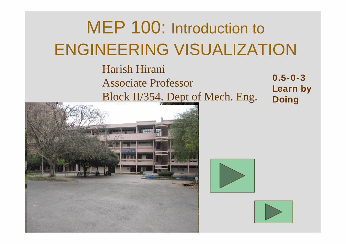
MEP 100: Introduction toENGINEERING VISUALIZATION
Harish HiraniAssociate ProfessorBlock II/354. Dept of Mech. Eng.I.I.T Delhi
0.5-0-3Learn by Doing
Course Objectives
To introduce students to:• Method of visualizing engineering
objects• Simple assemblies• CAD modeling and communicating
them to other professionals.
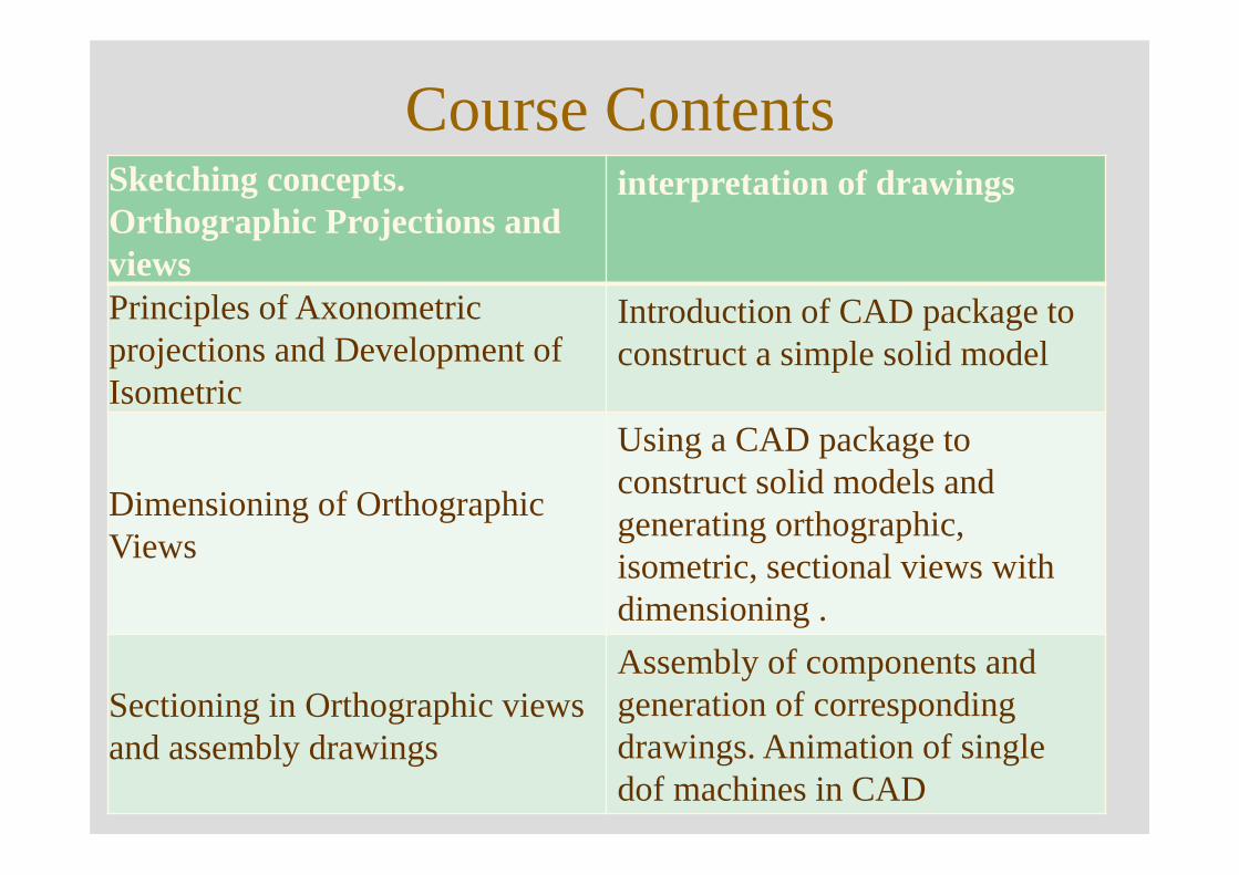
Course ContentsSketching concepts. Orthographic Projections and views
interpretation of drawings
Principles of Axonometric projections and Development of Isometric
Introduction of CAD package to construct a simple solid model
Dimensioning of Orthographic Views
Using a CAD package to construct solid models and generating orthographic, isometric, sectional views with dimensioning .
Sectioning in Orthographic views and assembly drawings
Assembly of components and generation of corresponding drawings. Animation of single dof machines in CAD
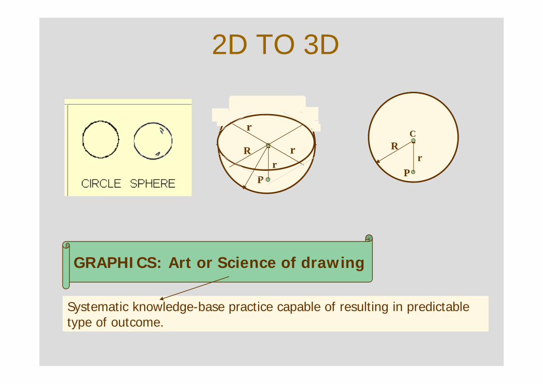
2D TO 3D
GRAPHICS: Art or Science of drawing
Systematic knowledge-base practice capable of resulting in predictable type of outcome.
Pr
RC
Pr
R
r
r
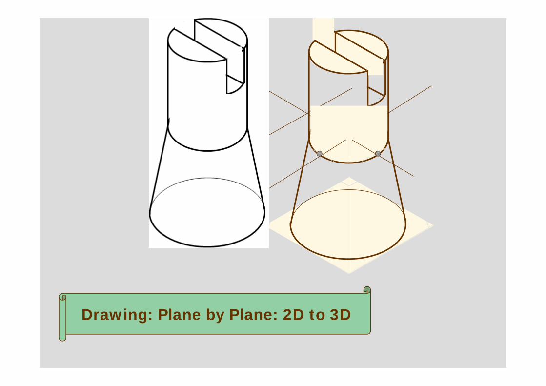
Drawing: Plane by Plane: 2D to 3D
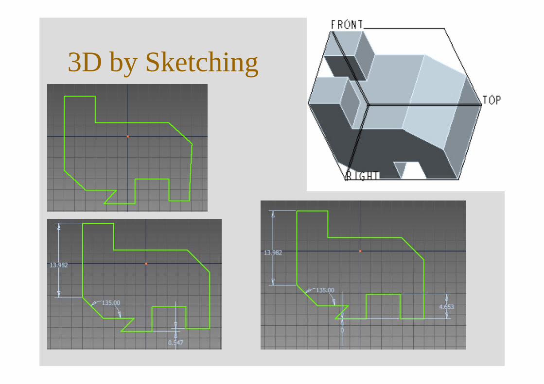
3D by Sketching
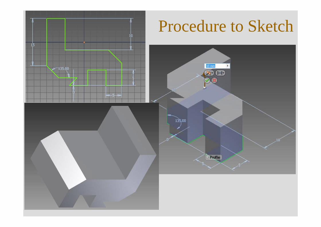
Procedure to Sketch
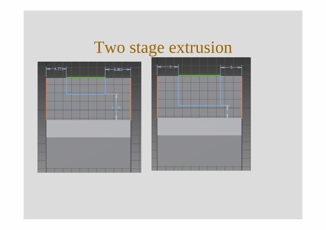
Two stage extrusion
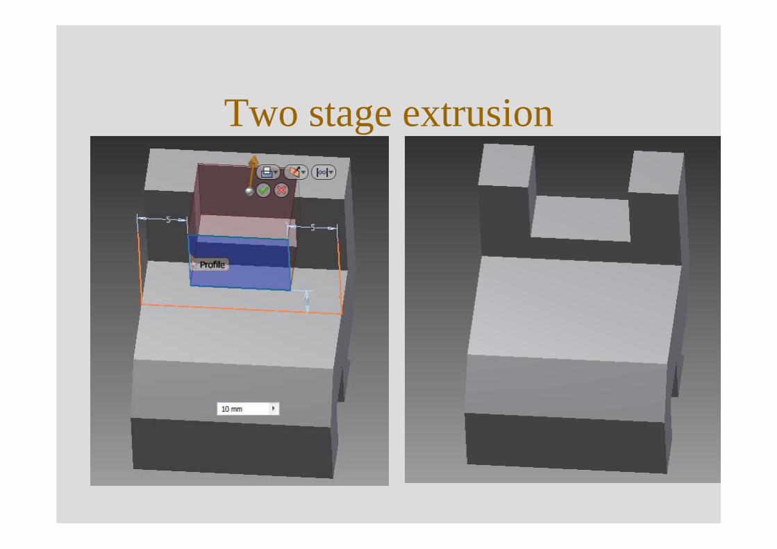
Two stage extrusion
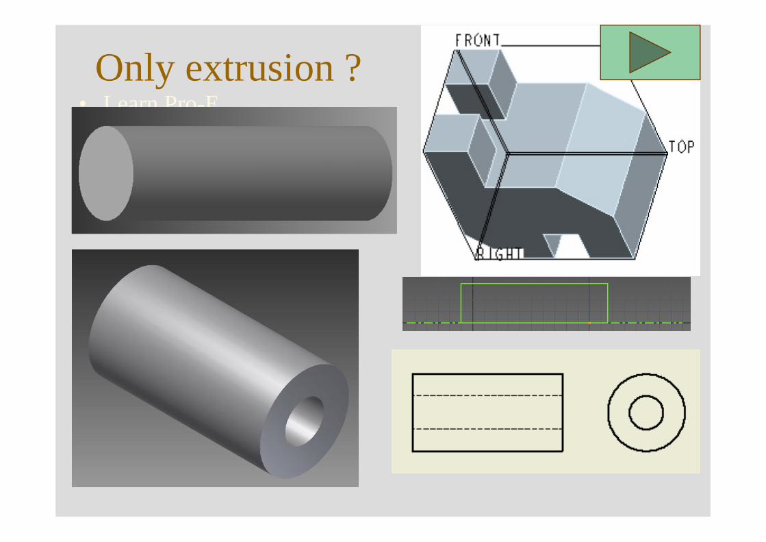
Only extrusion ?• Learn Pro-E.• Think few simple shapes.
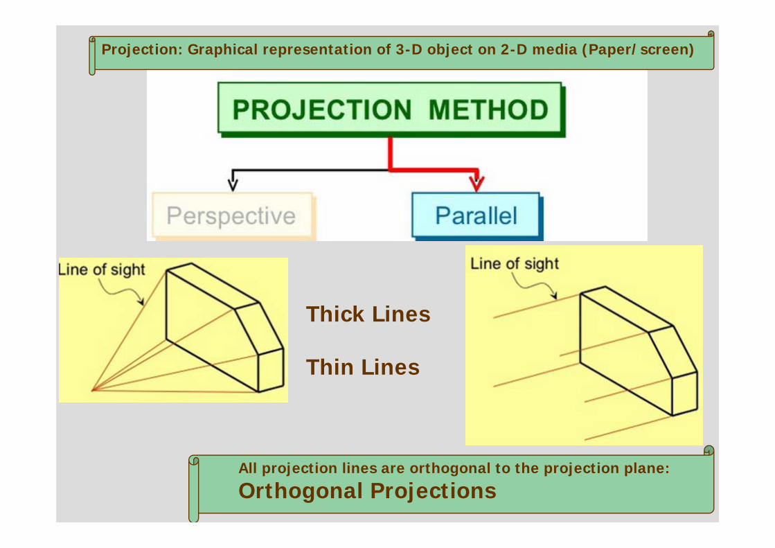
Projection: Graphical representation of 3-D object on 2-D media (Paper/screen)
Thick Lines
Thin Lines
All projection lines are orthogonal to the projection plane:
Orthogonal Projections
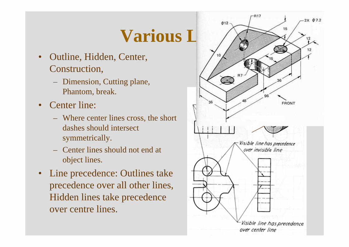
Various Lines• Outline, Hidden, Center,
Construction, – Dimension, Cutting plane,
Phantom, break.
• Center line: – Where center lines cross, the short
dashes should intersect symmetrically.
– Center lines should not end at object lines.
• Line precedence: Outlines take precedence over all other lines, Hidden lines take precedence over centre lines.
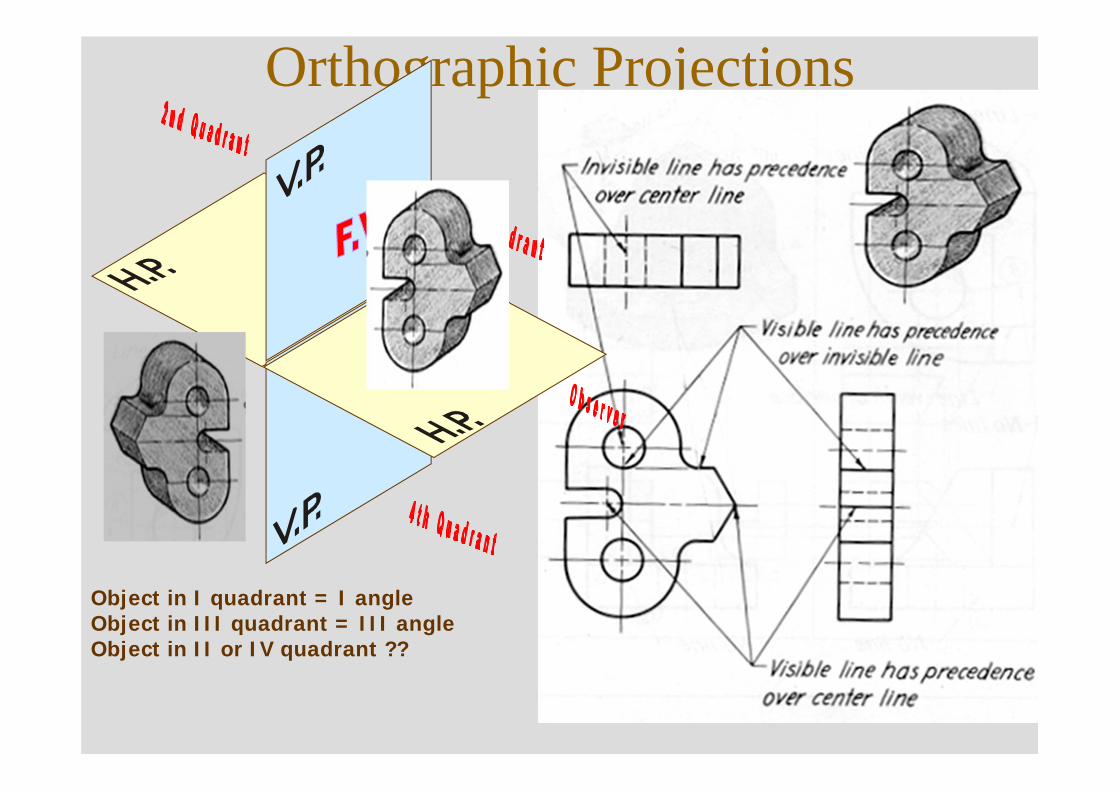
Orthographic Projections
X
Y
Object in I quadrant = I angleObject in III quadrant = III angleObject in II or IV quadrant ??
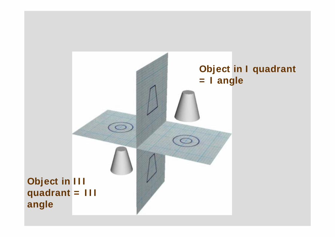
Object in I quadrant = I angle
Object in III quadrant = III angle
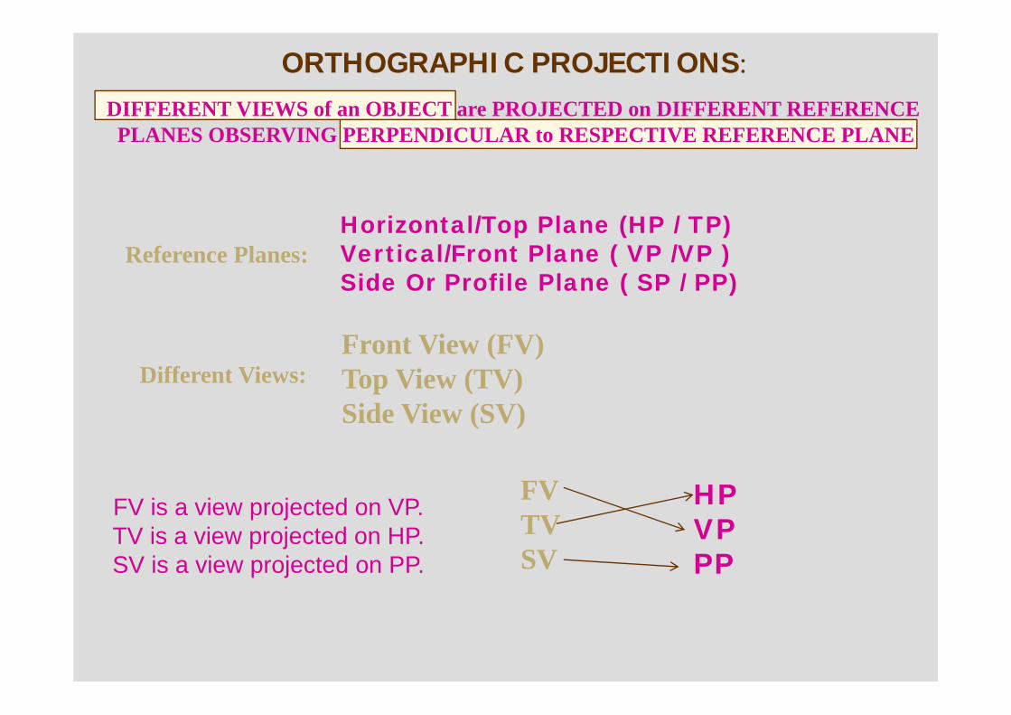
ORTHOGRAPHIC PROJECTIONS:
Horizontal/Top Plane (HP / TP) Vertical/Front Plane ( VP /VP ) Side Or Profile Plane ( SP / PP)
Reference Planes:
FV is a view projected on VP.TV is a view projected on HP.SV is a view projected on PP.
DIFFERENT VIEWS of an OBJECT are PROJECTED on DIFFERENT REFERENCE PLANES OBSERVING PERPENDICULAR to RESPECTIVE REFERENCE PLANE
Front View (FV)Top View (TV)Side View (SV)
Different Views:
FVTVSV
HP VP PP
x y
FRONT VIEW
TOP VIEW
L.H.SIDE VIEW
FOR T.V.
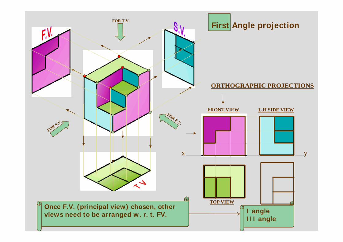
ORTHOGRAPHIC PROJECTIONS
First Angle projection
Once F.V. (principal view) chosen, other views need to be arranged w. r. t. FV. I angle
III angle
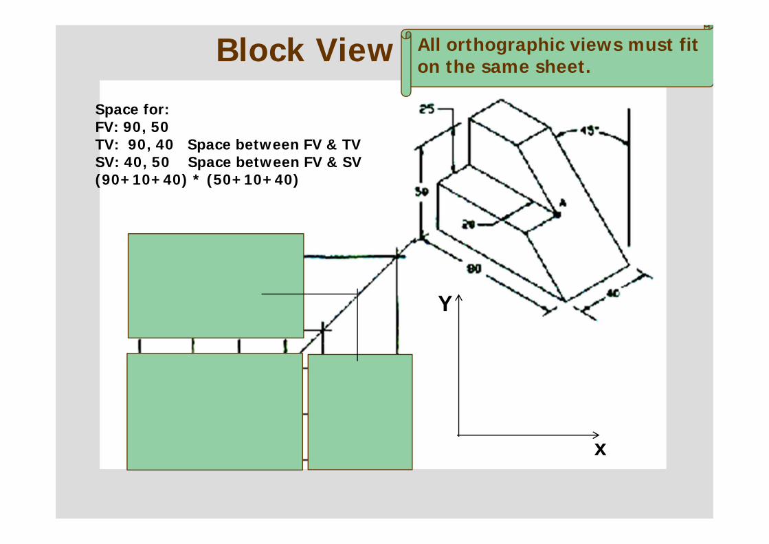
Space for:FV: 90, 50TV: 90, 40 Space between FV & TVSV: 40, 50 Space between FV & SV(90+10+40) * (50+10+40)
x
Y
Block View All orthographic views must fit on the same sheet.
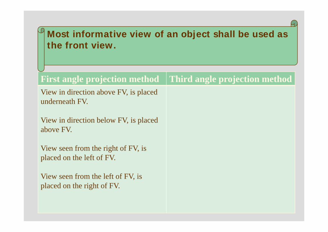
First angle projection method Third angle projection methodView in direction above FV, is placed underneath FV.
View in direction below FV, is placed above FV.
View seen from the right of FV, is placed on the left of FV.
View seen from the left of FV, is placed on the right of FV.
Most informative view of an object shall be used as the front view.
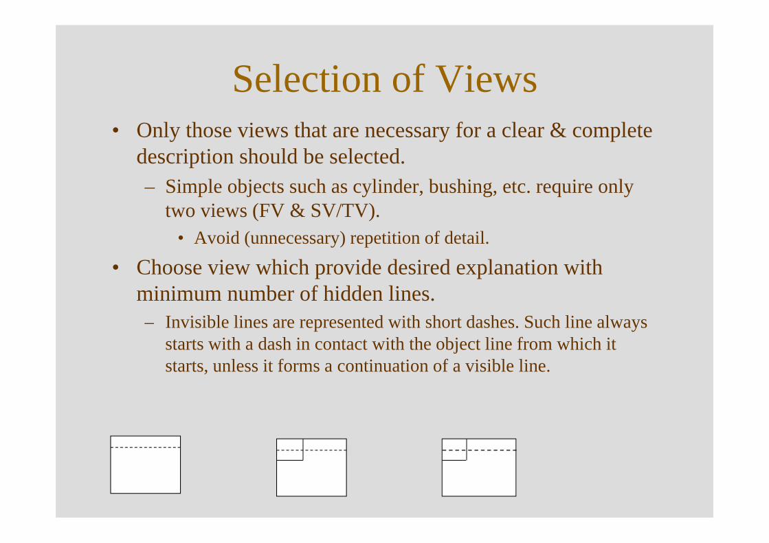
Selection of Views• Only those views that are necessary for a clear & complete
description should be selected.– Simple objects such as cylinder, bushing, etc. require only
two views (FV & SV/TV).• Avoid (unnecessary) repetition of detail.
• Choose view which provide desired explanation with minimum number of hidden lines.– Invisible lines are represented with short dashes. Such line always
starts with a dash in contact with the object line from which it starts, unless it forms a continuation of a visible line.
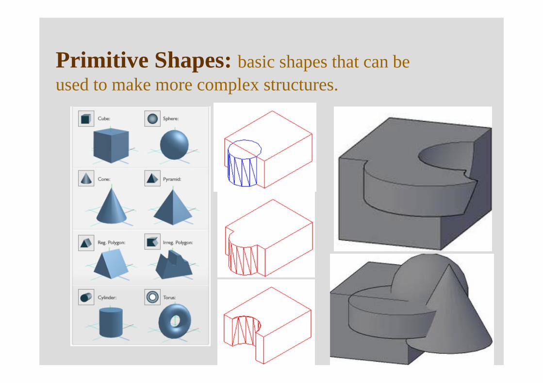
Primitive Shapes: basic shapes that can be used to make more complex structures.
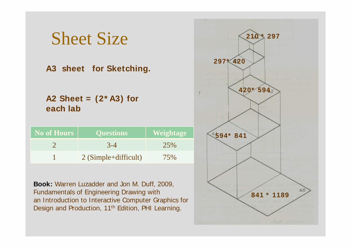
Sheet Size
841 * 1189
594* 841
420* 594
297* 420
210 * 297
A3 sheet for Sketching.
A2 Sheet = (2*A3) for each lab
No of Hours Questions Weightage2 3-4 25%1 2 (Simple+difficult) 75%
Book: Warren Luzadder and Jon M. Duff, 2009, Fundamentals of Engineering Drawing withan Introduction to Interactive Computer Graphics for Design and Production, 11th Edition, PHI Learning.
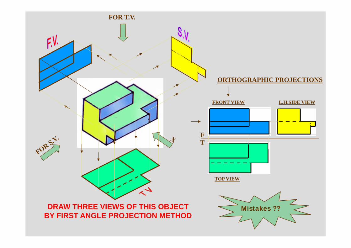
FOR T.V.
FT
FRONT VIEW
TOP VIEW
L.H.SIDE VIEW
ORTHOGRAPHIC PROJECTIONS
DRAW THREE VIEWS OF THIS OBJECTBY FIRST ANGLE PROJECTION METHOD
Mistakes ??
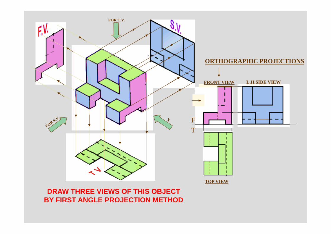
FOR T.V.
ORTHOGRAPHIC PROJECTIONS
FT
FRONT VIEW
TOP VIEW
L.H.SIDE VIEW
DRAW THREE VIEWS OF THIS OBJECTBY FIRST ANGLE PROJECTION METHOD
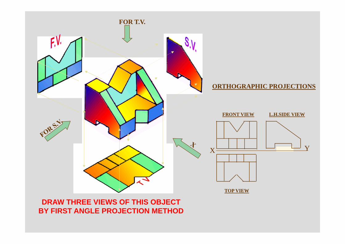
FOR T.V.
ORTHOGRAPHIC PROJECTIONS
DRAW THREE VIEWS OF THIS OBJECTBY FIRST ANGLE PROJECTION METHOD
FRONT VIEW
TOP VIEW
L.H.SIDE VIEW
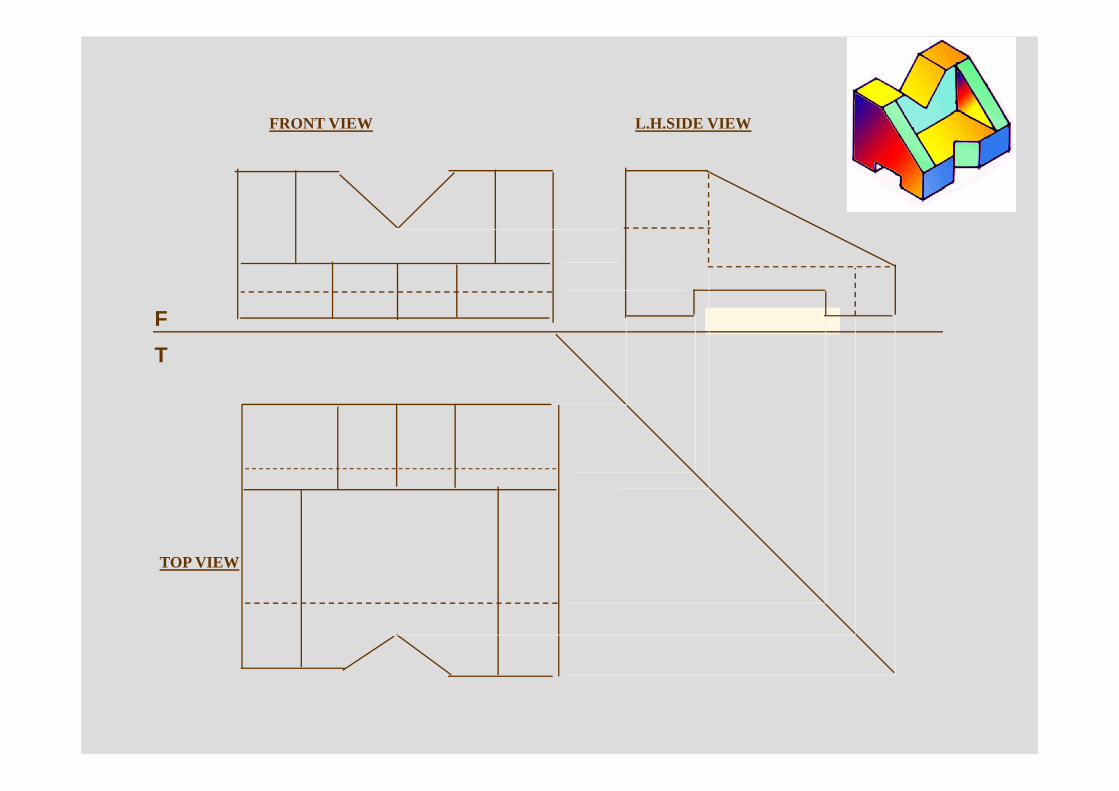
X Y
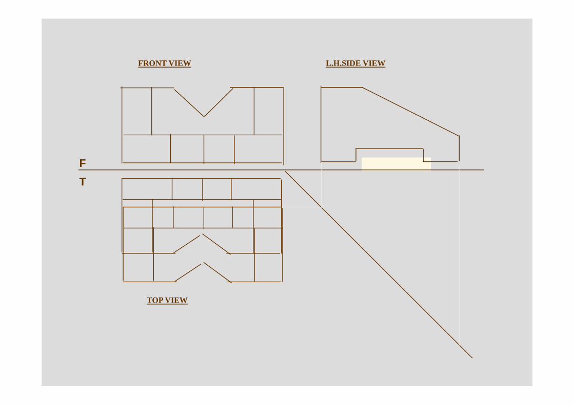
FRONT VIEW
TOP VIEW
L.H.SIDE VIEW
F
T
FRONT VIEW
TOP VIEW
L.H.SIDE VIEW
F
T
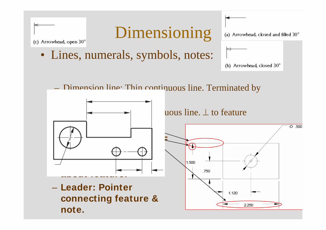
Dimensioning• Lines, numerals, symbols, notes:
– Dimension line: Thin continuous line. Terminated by arrowheads.
– Extension line: Thin continuous line. ⊥ to feature– Arrowhead:
Closed/Open. Length = 3* Width.
– Note: Specific info about feature.
– Leader: Pointer connecting feature & note.
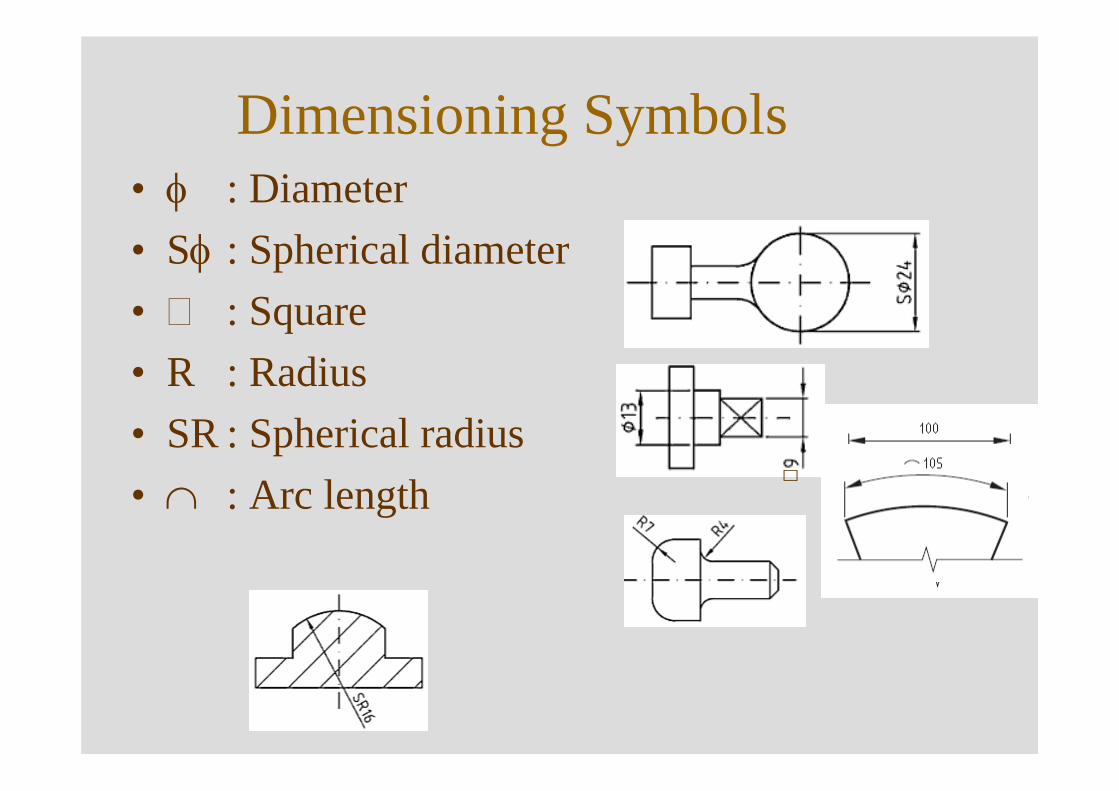
Dimensioning Symbols• φ : Diameter• Sφ : Spherical diameter• : Square• R : Radius• SR : Spherical radius• ∩ : Arc length
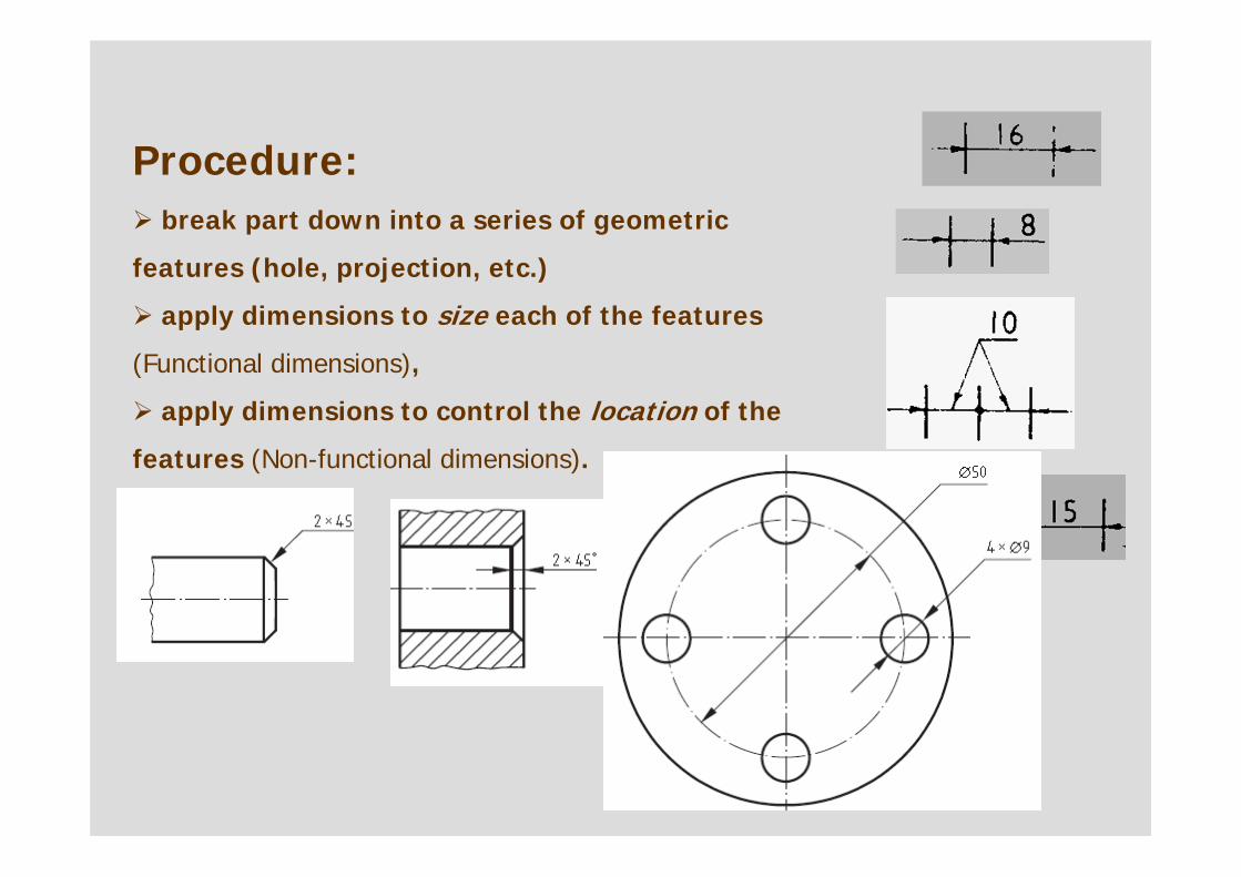
Procedure:break part down into a series of geometric
features (hole, projection, etc.)
apply dimensions to size each of the features
(Functional dimensions),
apply dimensions to control the location of the
features (Non-functional dimensions).
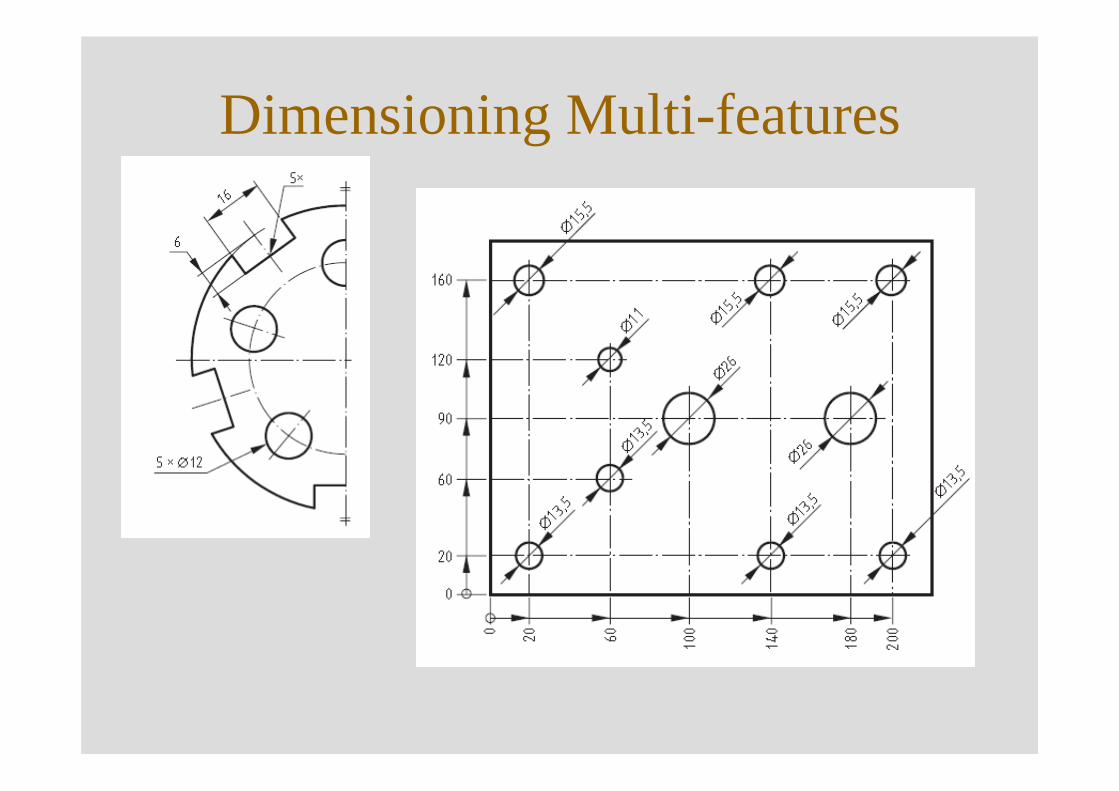
Dimensioning Multi-features
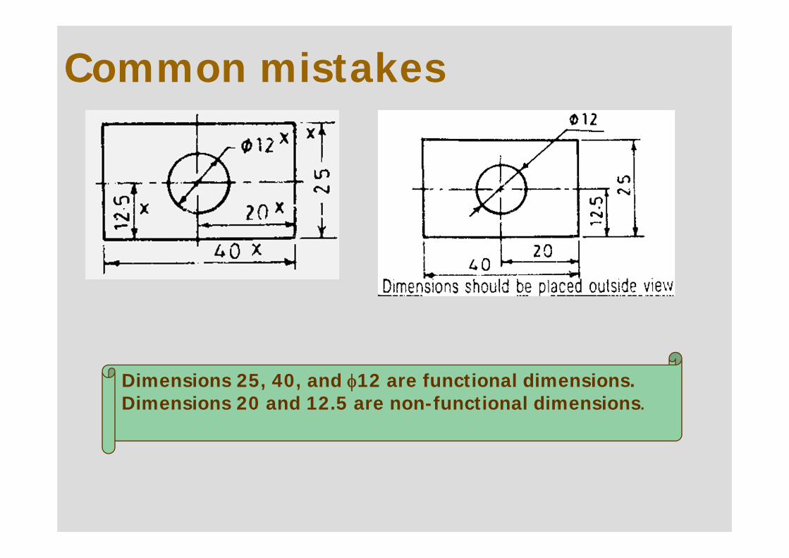
Common mistakes
Dimensions 25, 40, and φ12 are functional dimensions. Dimensions 20 and 12.5 are non-functional dimensions.
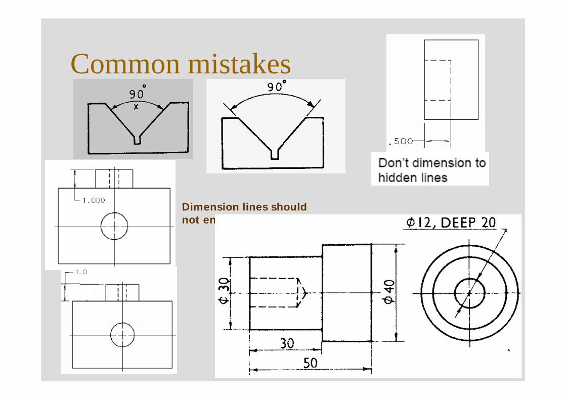
Common mistakes
Dimension lines should not end at object lines
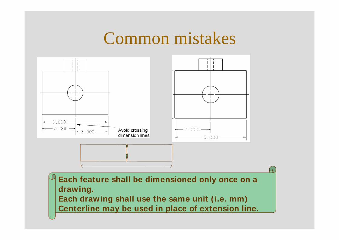
Common mistakes
Each feature shall be dimensioned only once on a drawing.Each drawing shall use the same unit (i.e. mm)Centerline may be used in place of extension line.
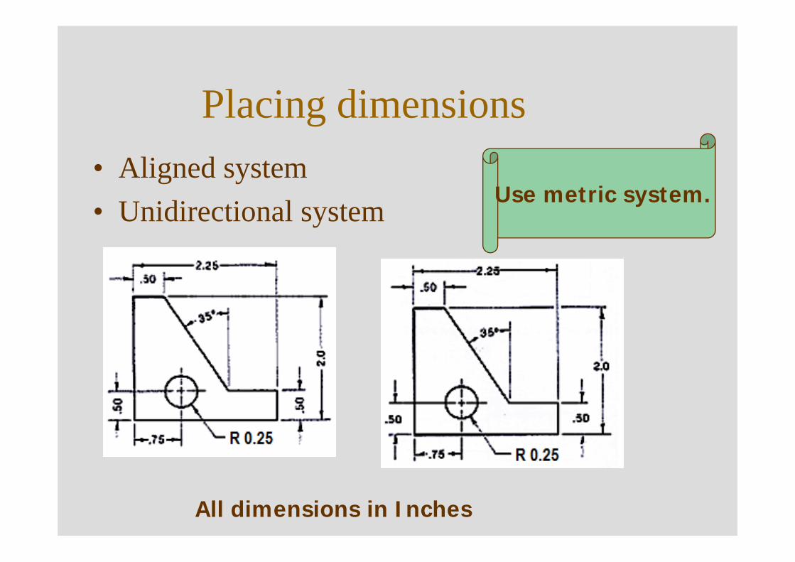
Placing dimensions• Aligned system• Unidirectional system Use metric system.
All dimensions in Inches
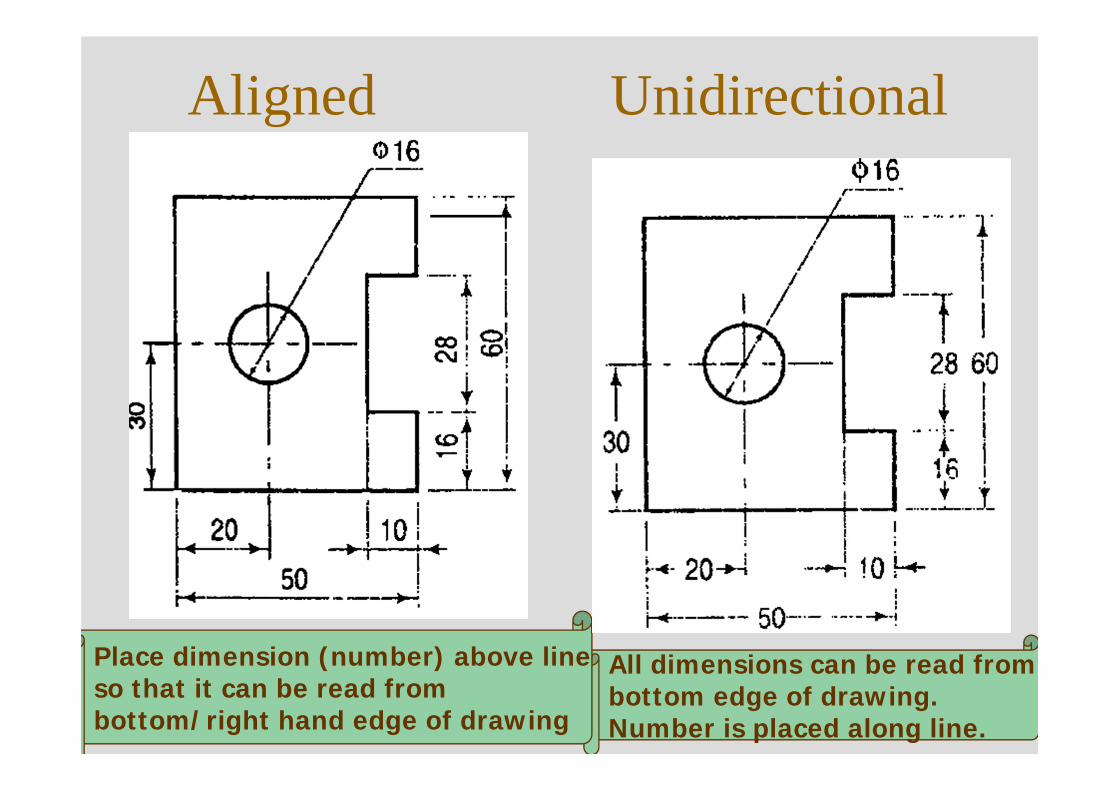
Aligned Unidirectional
All dimensions can be read frombottom edge of drawing. Number is placed along line.
Place dimension (number) above lineso that it can be read from bottom/right hand edge of drawing
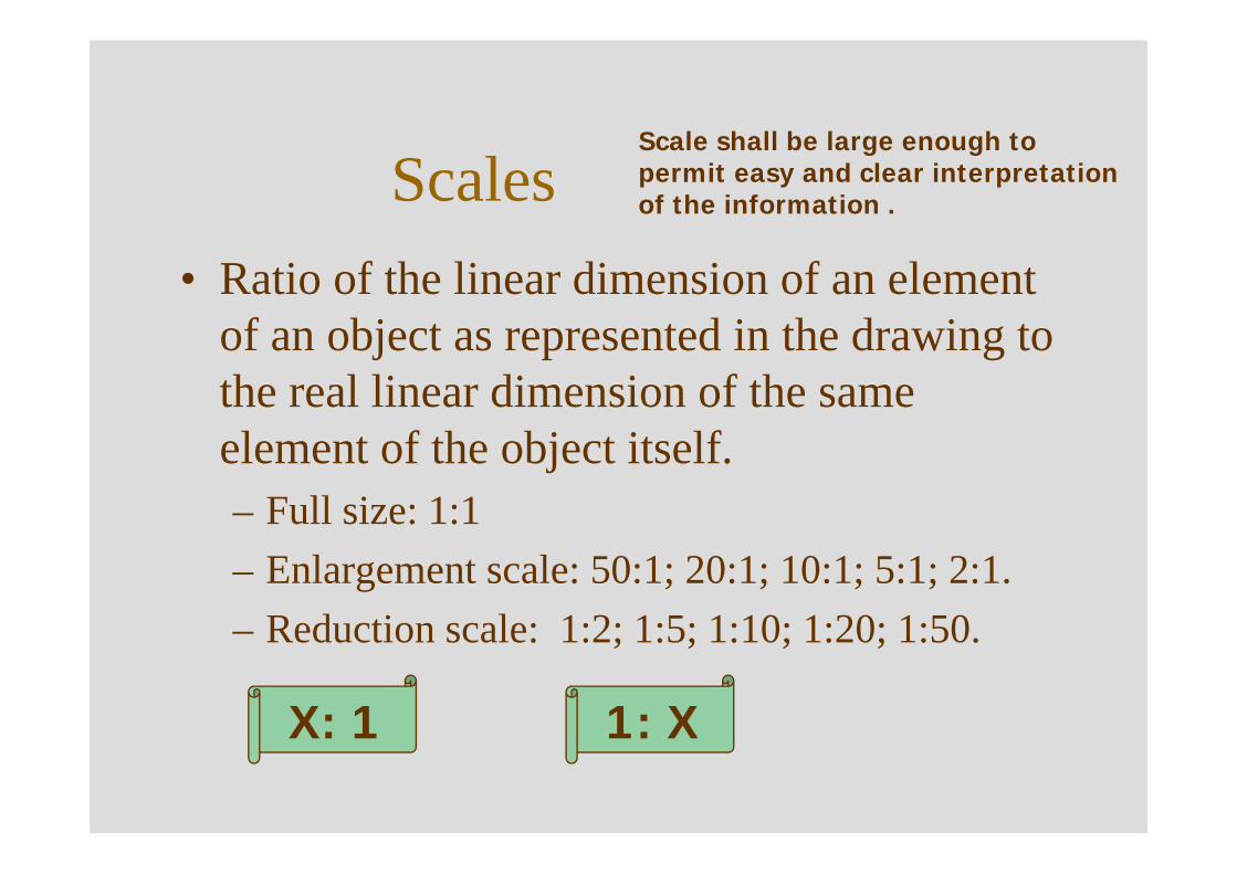
Scales• Ratio of the linear dimension of an element
of an object as represented in the drawing to the real linear dimension of the same element of the object itself. – Full size: 1:1– Enlargement scale: 50:1; 20:1; 10:1; 5:1; 2:1.– Reduction scale: 1:2; 1:5; 1:10; 1:20; 1:50.
X: 1 1: X
Scale shall be large enough to permit easy and clear interpretation of the information .
SV
TV
yx
FV
30
30
10
30 10 30
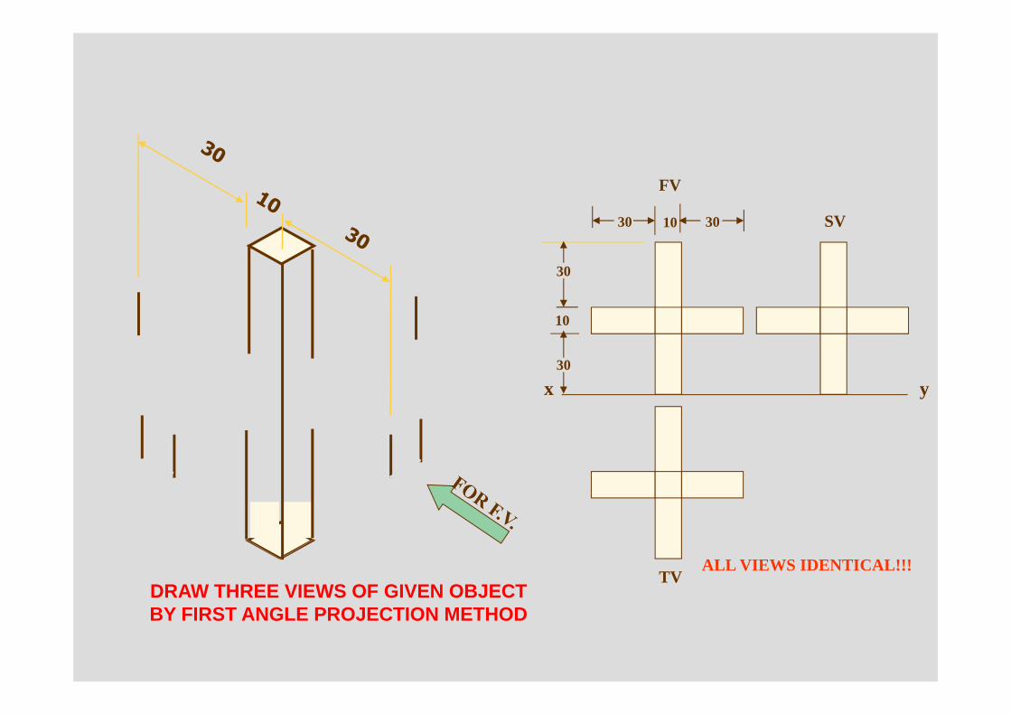
ALL VIEWS IDENTICAL!!!DRAW THREE VIEWS OF GIVEN OBJECTBY FIRST ANGLE PROJECTION METHOD
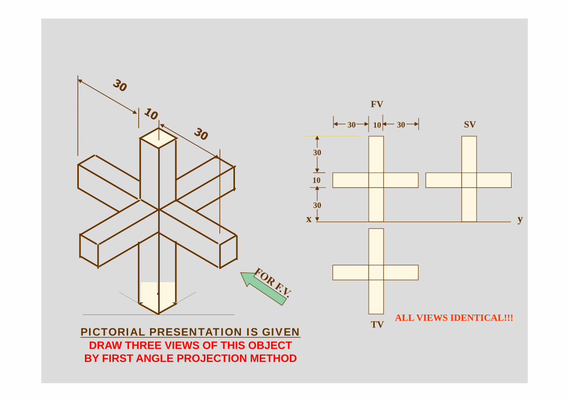
SV
TV
yx
FV
30
30
10
30 10 30
ALL VIEWS IDENTICAL!!!PICTORIAL PRESENTATION IS GIVEN
DRAW THREE VIEWS OF THIS OBJECTBY FIRST ANGLE PROJECTION METHOD
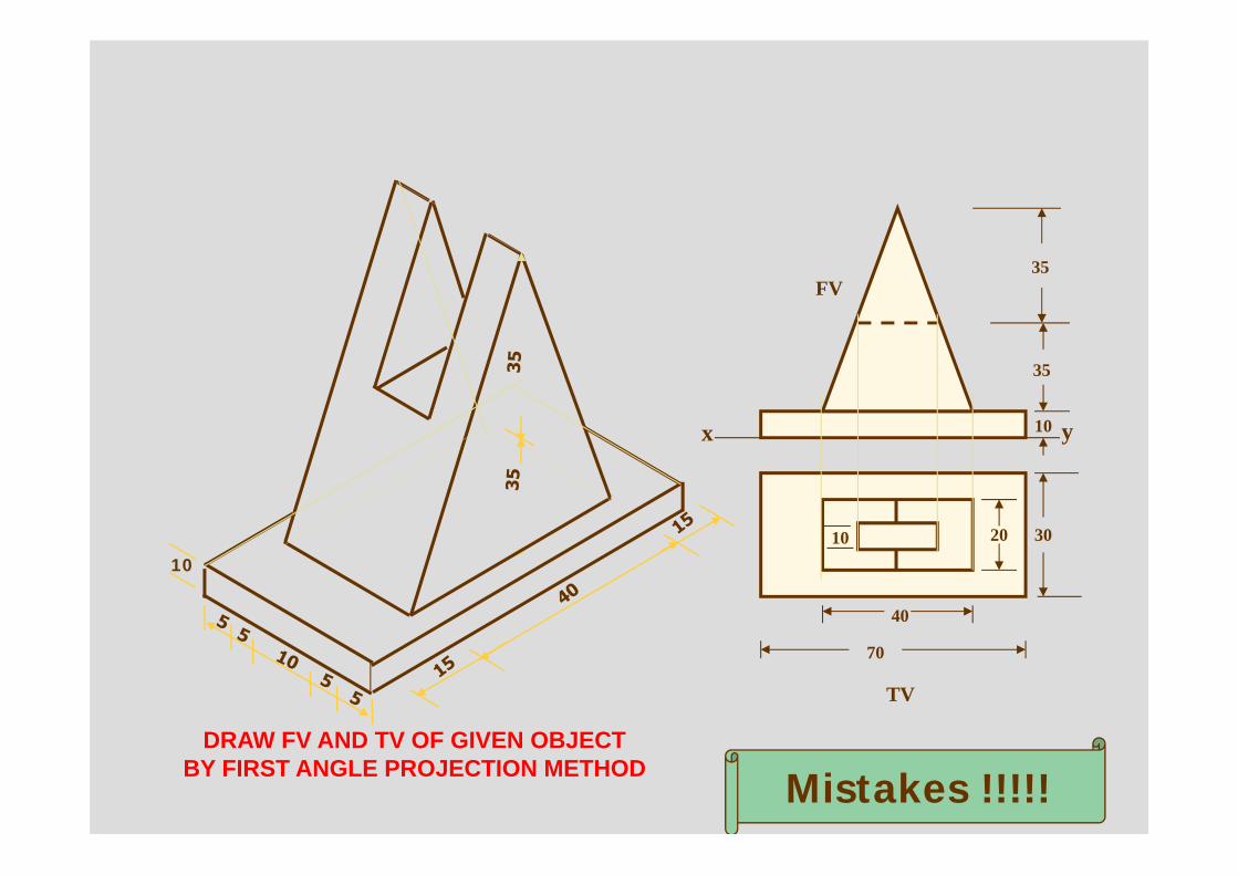
x y
FV35
35
10
TV
302010
40
70
DRAW FV AND TV OF GIVEN OBJECTBY FIRST ANGLE PROJECTION METHOD Mistakes !!!!!
10
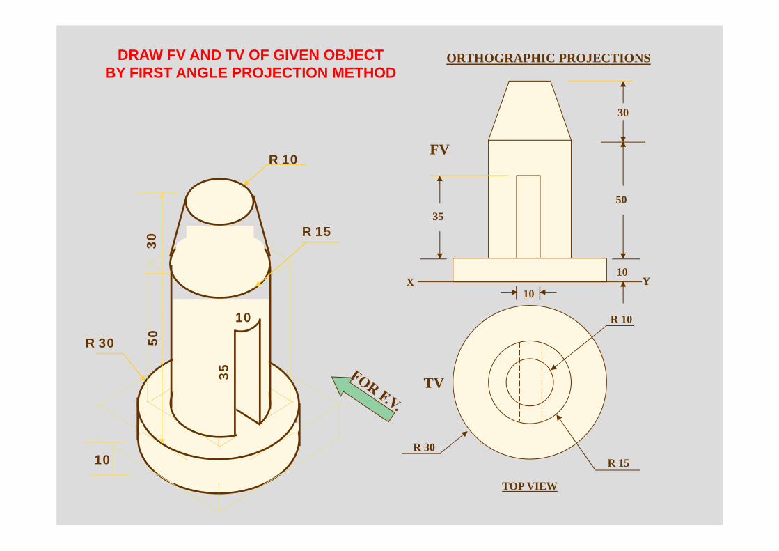
R 10
R 15R 30
TV
10
30
50
10
35
FV
X Y
DRAW FV AND TV OF GIVEN OBJECTBY FIRST ANGLE PROJECTION METHOD
ORTHOGRAPHIC PROJECTIONS
TOP VIEW
R 10
R 15
R 30
10
3050
10
35
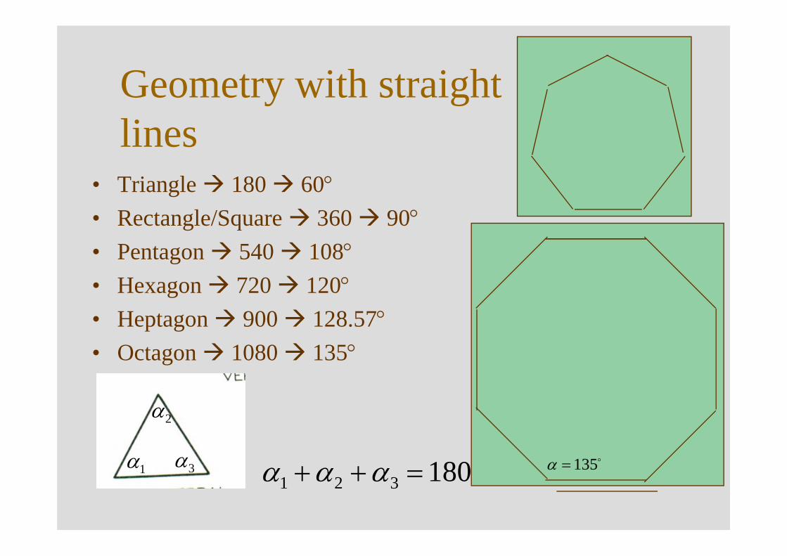
Geometry with straight lines
• Triangle 180 60°• Rectangle/Square 360 90°• Pentagon 540 108°• Hexagon 720 120°• Heptagon 900 128.57°• Octagon 1080 135°
180321 =++ ααα1α
2α
3α o135=α
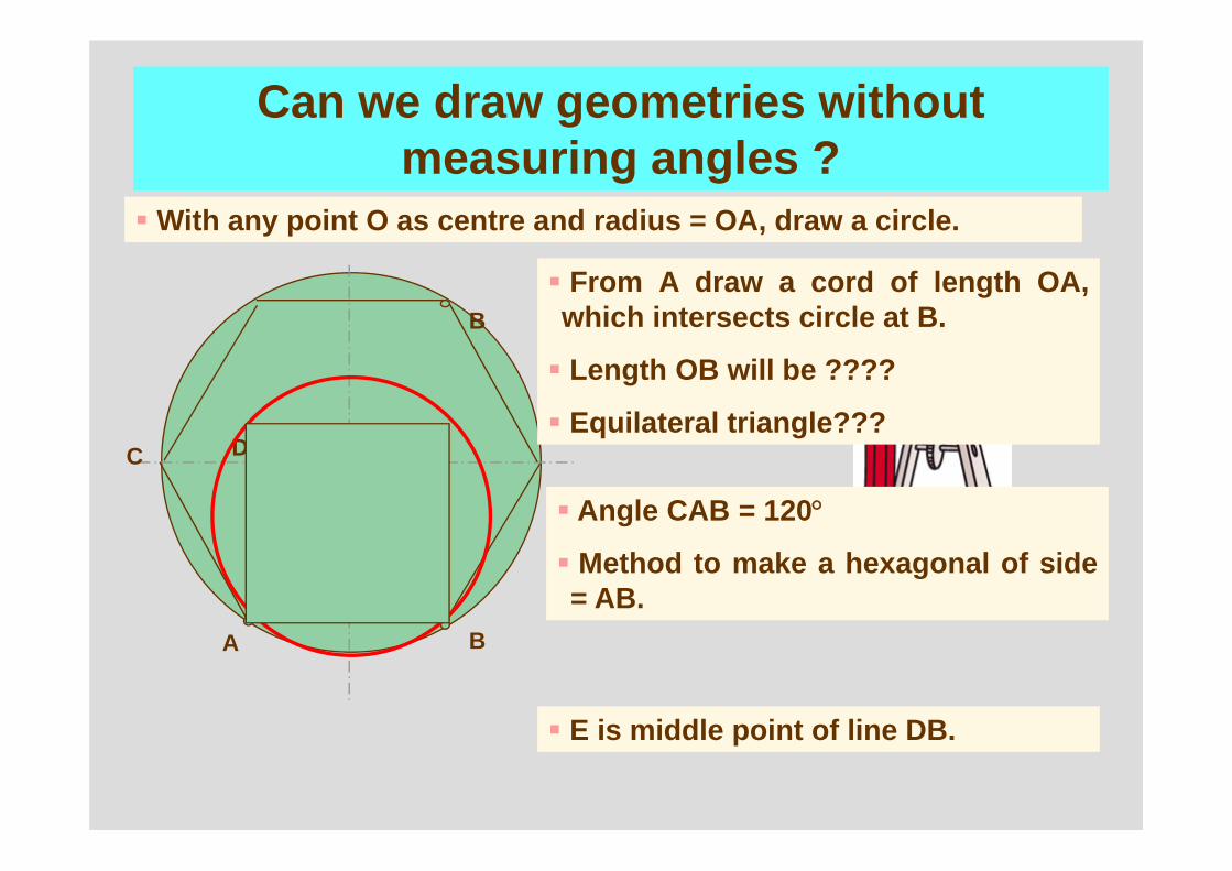
With any point O as centre and radius = OA, draw a circle.
Can we draw geometries without measuring angles ?
O
A B
From A draw a cord of length OA,which intersects circle at B.
Length OB will be ????
Equilateral triangle???C
Angle CAB = 120°
Method to make a hexagonal of side= AB.
D
E
E is middle point of line DB.
B
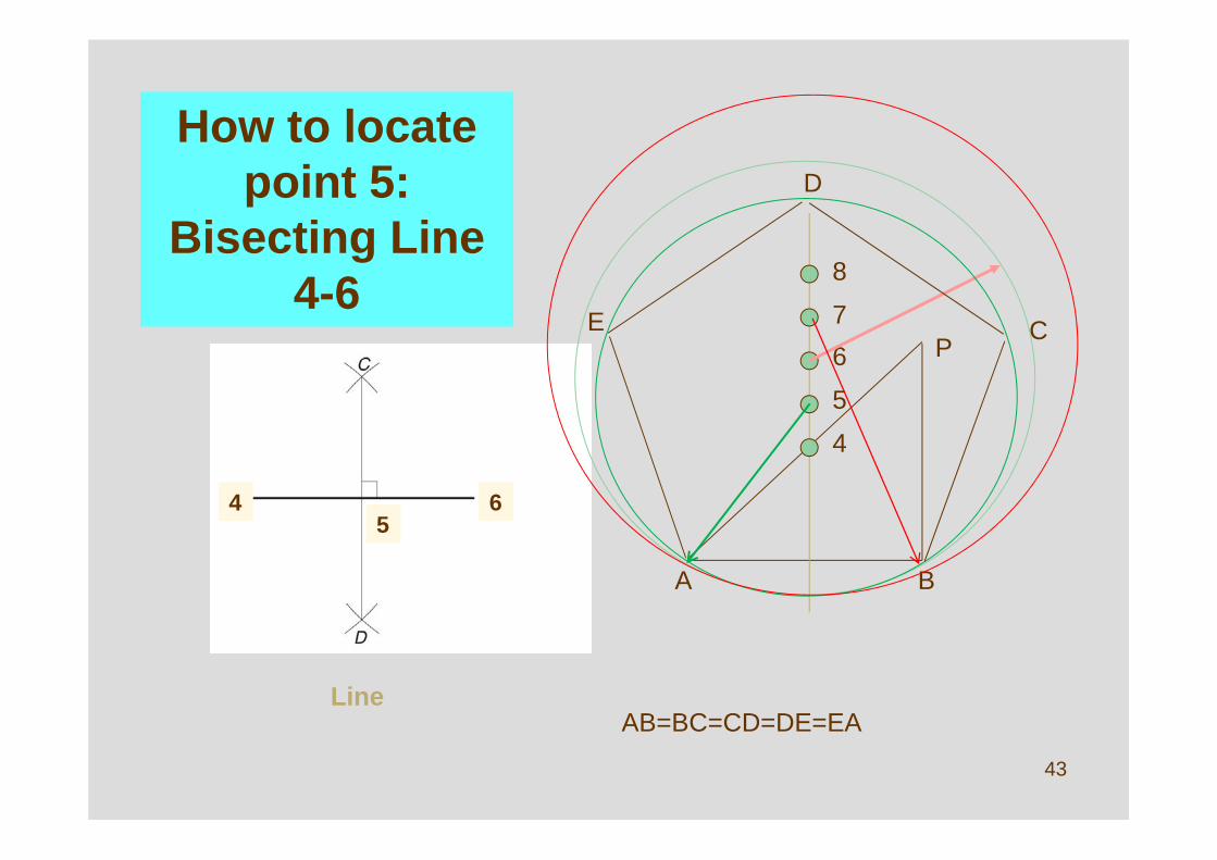
How to locate point 5:
Bisecting Line 4-6
Line
43
E4 65
A
4
6 P
B
5
7
8
C
D
E
AB=BC=CD=DE=EA
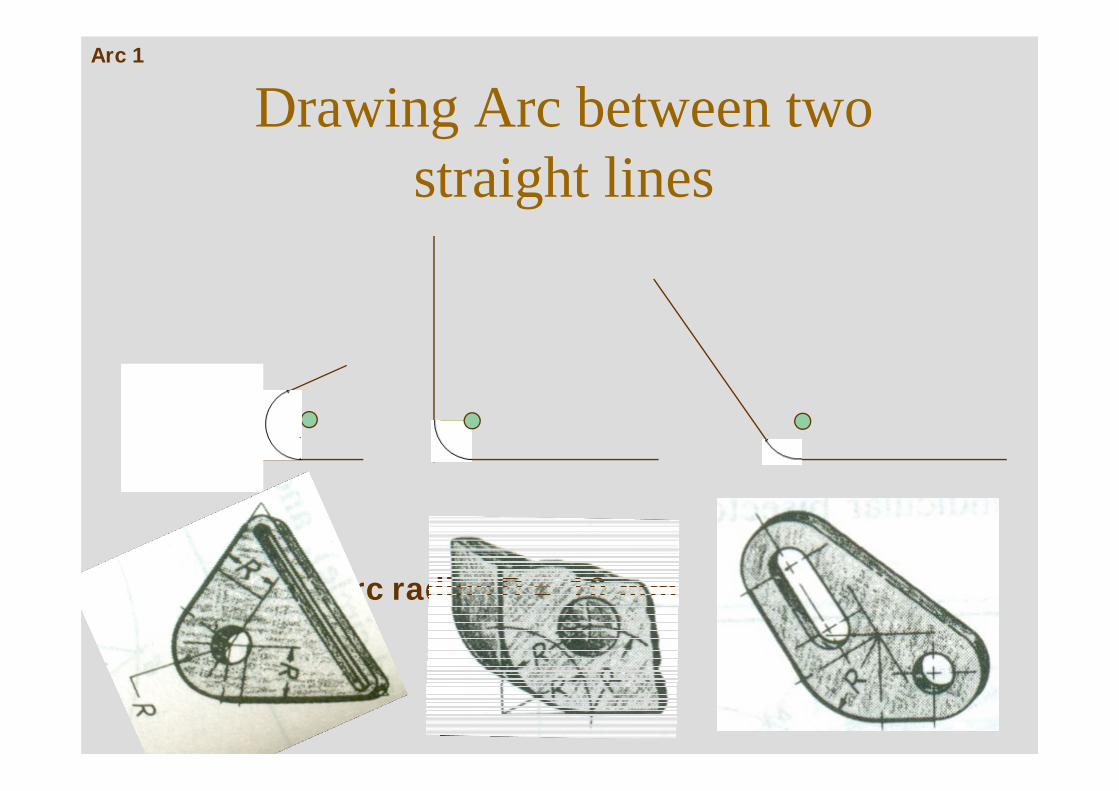
Drawing Arc between two straight lines
Arc radius R = 10 mm
Arc 1
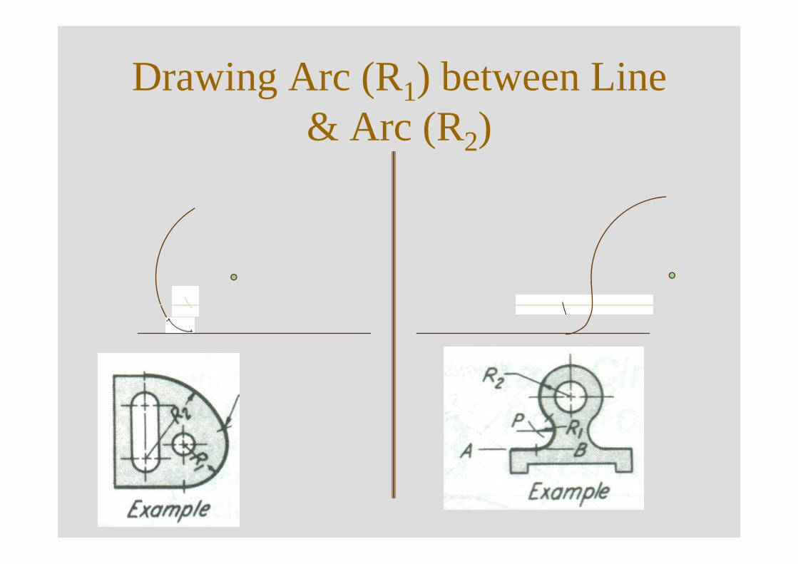
Drawing Arc (R1) between Line & Arc (R2)
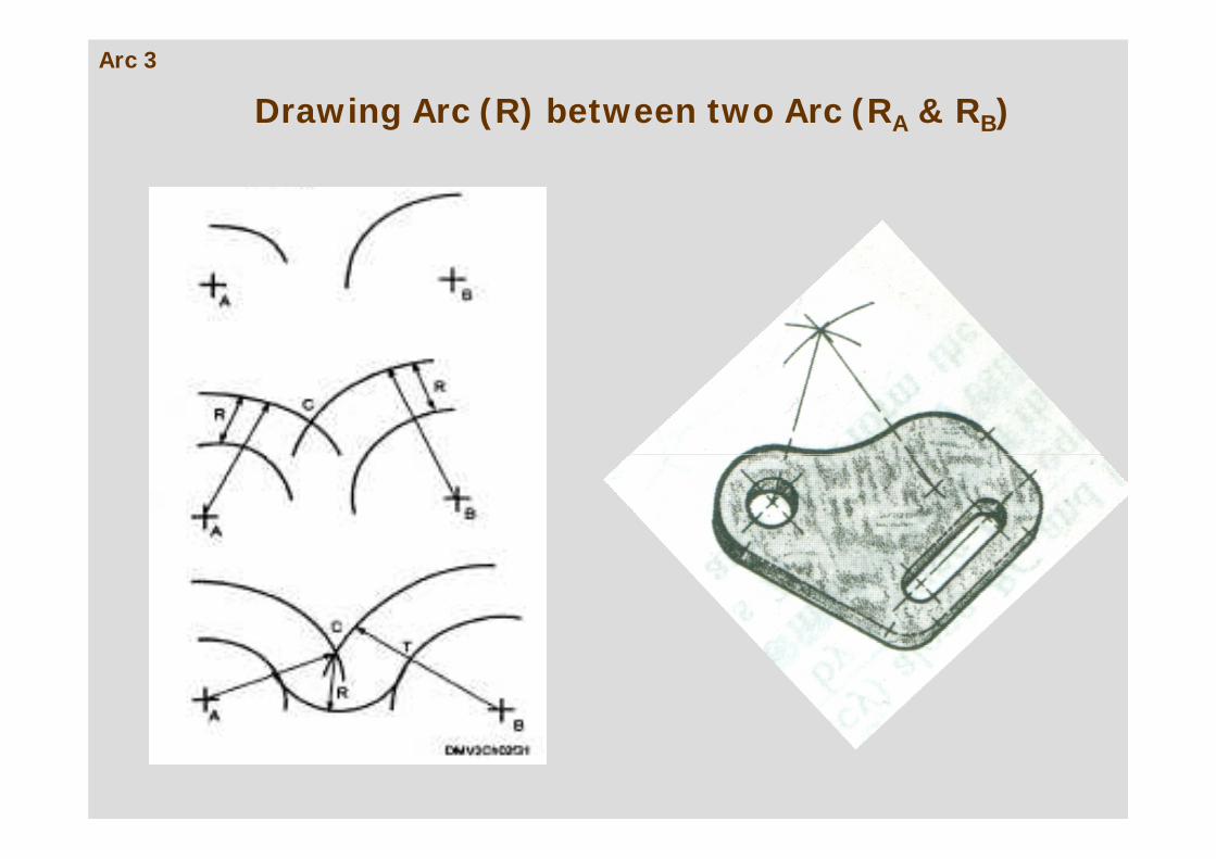
Drawing Arc (R) between two Arc (RA & RB)Arc 3
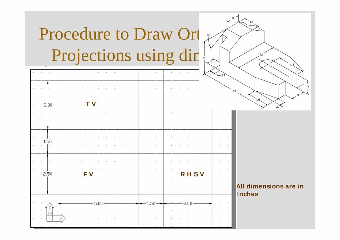
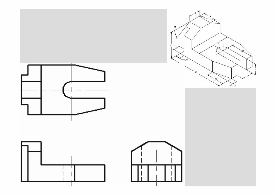
Procedure to Draw Orthographic Projections using dimensions
All dimensions are in Inches
F V
T V
R H S V
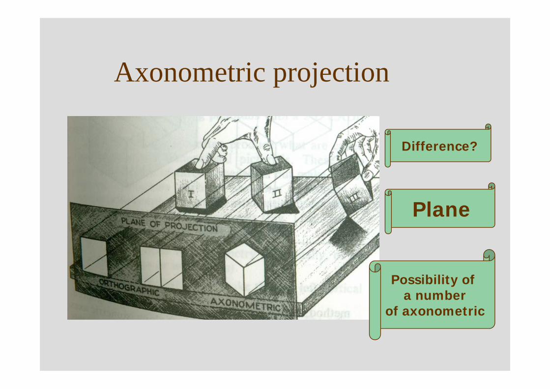
Axonometric projection
Difference?
Plane
Possibility of a number
of axonometric
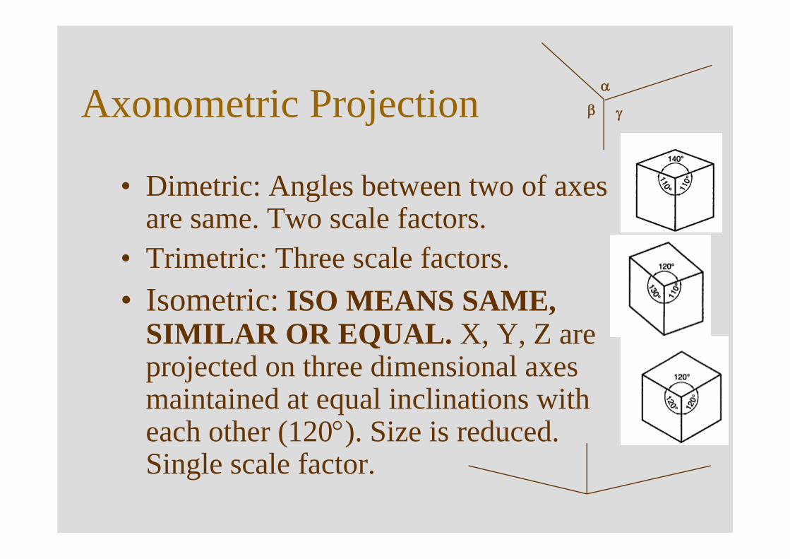
Axonometric Projection
• Dimetric: Angles between two of axes are same. Two scale factors.
• Trimetric: Three scale factors.• Isometric: ISO MEANS SAME,
SIMILAR OR EQUAL. X, Y, Z are projected on three dimensional axes maintained at equal inclinations with each other (120°). Size is reduced. Single scale factor.
α
γβ
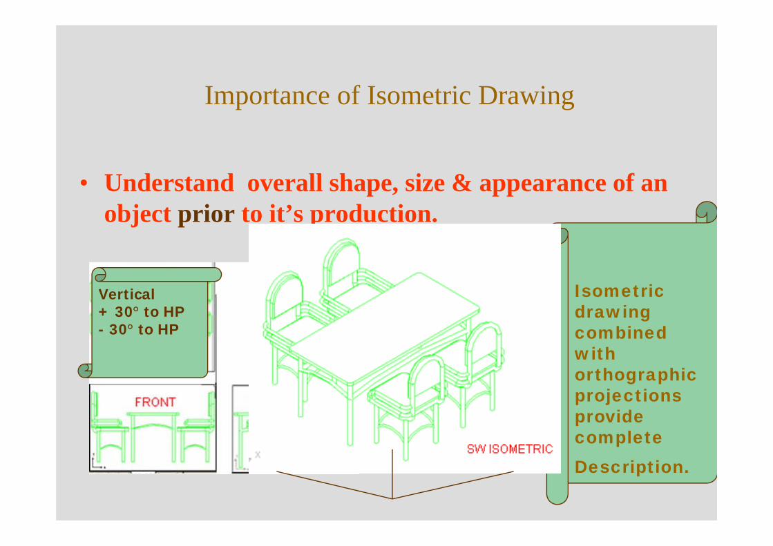
Importance of Isometric Drawing
• Understand overall shape, size & appearance of an object prior to it’s production.
Isometric drawing combined with orthographic projections provide completeDescription.
Vertical+ 30° to HP- 30° to HP
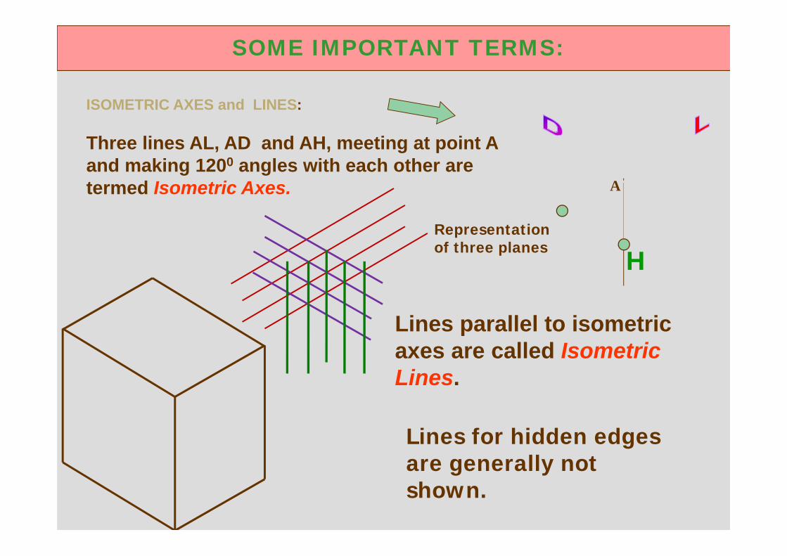
ISOMETRIC AXES and LINES:
Three lines AL, AD and AH, meeting at point A and making 1200 angles with each other are termed Isometric Axes.
H
A
SOME IMPORTANT TERMS:
Lines parallel to isometric axes are called Isometric Lines.
Lines for hidden edges are generally not shown.
Representation of three planes
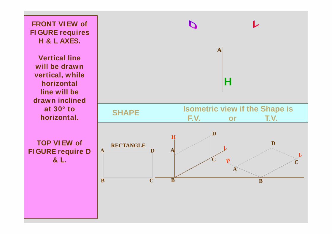
SHAPE Isometric view if the Shape isF.V. or T.V.
A
B
RECTANGLED
C
H D
A
B
C
A
B
D
C
FRONT VIEW of FIGURE requires
H & L AXES.
Vertical linewill be drawn vertical, while
horizontalline will be
drawn inclinedat 30° to
horizontal.
TOP VIEW of FIGURE require D
& L.
H
A
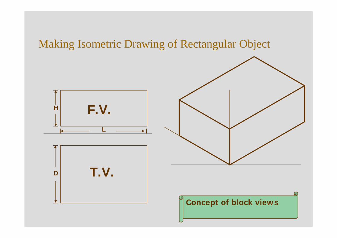
Making Isometric Drawing of Rectangular Object
L
H
D
F.V.
T.V.
Concept of block views
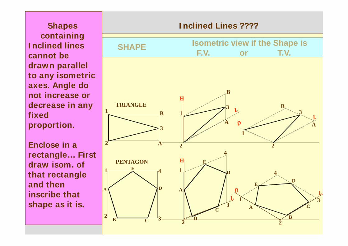
SHAPE Isometric view if the Shape isF.V. or T.V.
TRIANGLEH
1
2
3
A
B3
1
2
A
B
3
1
2
A
B
H
1
2 3
4PENTAGON
A
B C
D
E 1
2
3
4
A
B
C
D
E
1
2
3
4
A
B
C
DE
Shapes containing
Inclined lines cannot be drawn parallel to any isometric axes. Angle do not increase or decrease in any fixed proportion.
Enclose in a rectangle… First draw isom. of that rectangle and then inscribe that shape as it is.
Inclined Lines ????
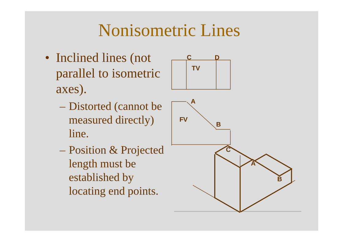
Nonisometric Lines• Inclined lines (not
parallel to isometric axes).– Distorted (cannot be
measured directly) line.
– Position & Projected length must be established by locating end points.
FV
TV
A
B
C D
A
B
C
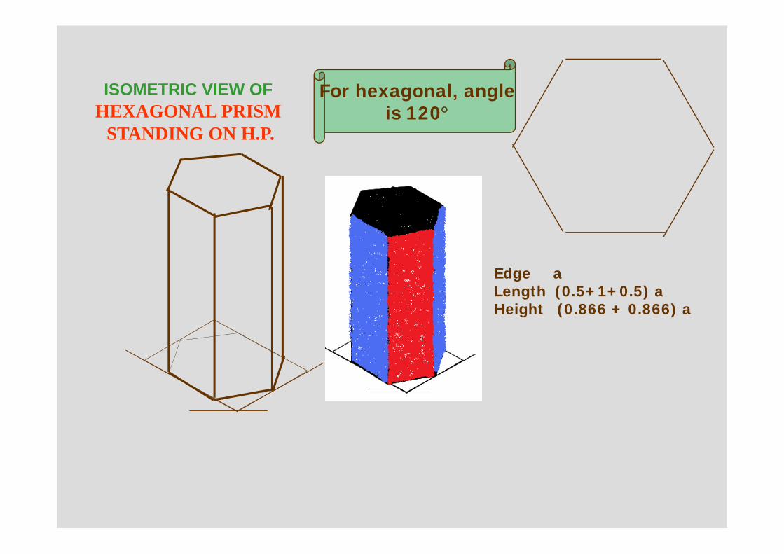
ISOMETRIC VIEW OFHEXAGONAL PRISM
STANDING ON H.P.
For hexagonal, angleis 120°
Edge aLength (0.5+1+0.5) aHeight (0.866 + 0.866) a
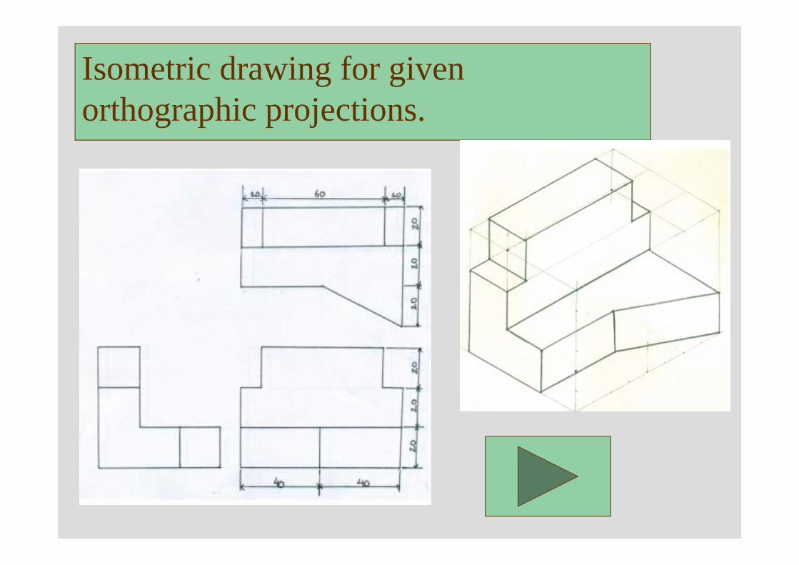
Isometric drawing for given orthographic projections.
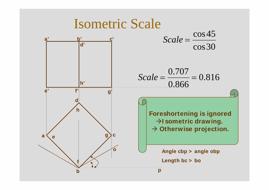
Isometric Scale
h
d
a cg
f
e
b
b’
e’ g’f’
a’ c’
h’
d’ 30cos45cos
=Scale
816.0866.0707.0
==Scale
Foreshortening is ignoredIsometric drawing.
Otherwise projection.
o Angle cbp > angle obp
Length bc > bo
p
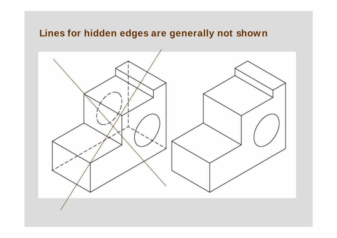
Lines for hidden edges are generally not shown
.
40
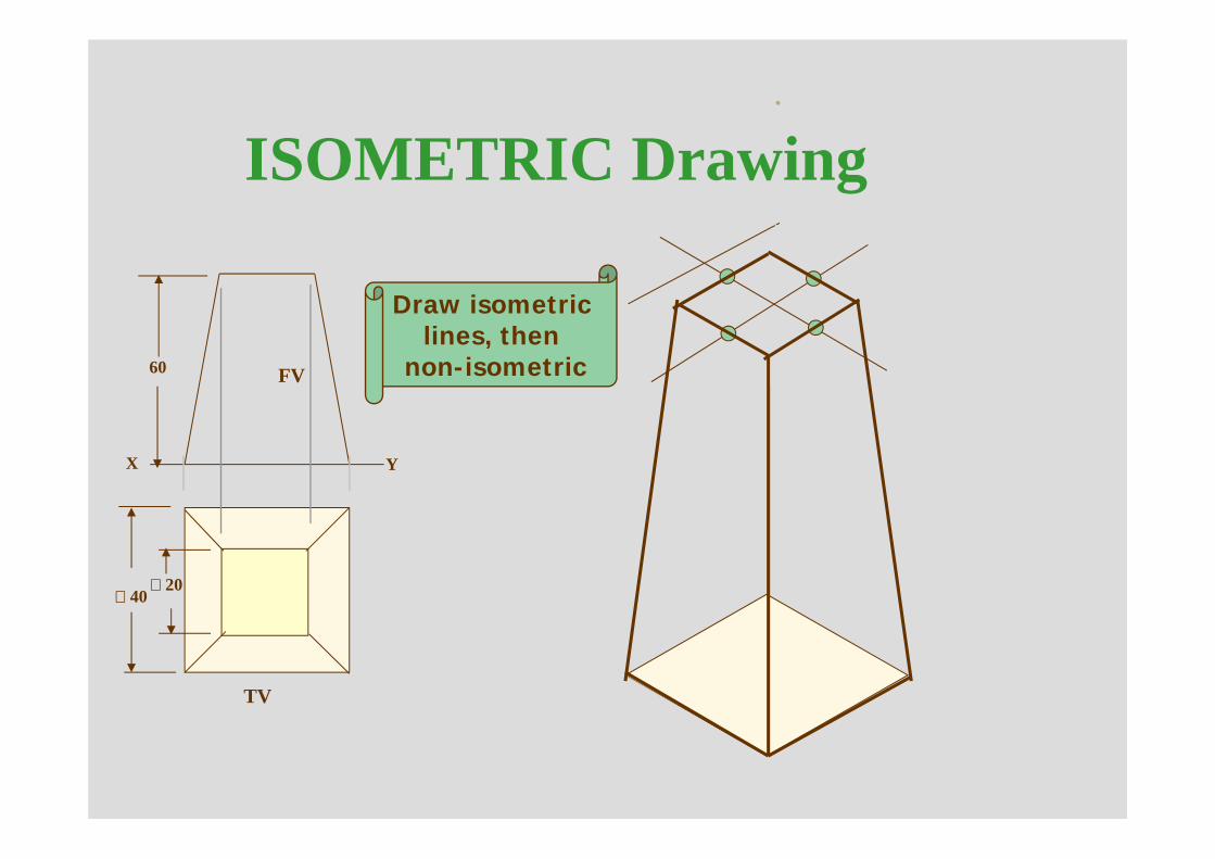
ISOMETRIC Drawing
Draw isometric lines, then
non-isometric
20
60
X Y
FV
TV
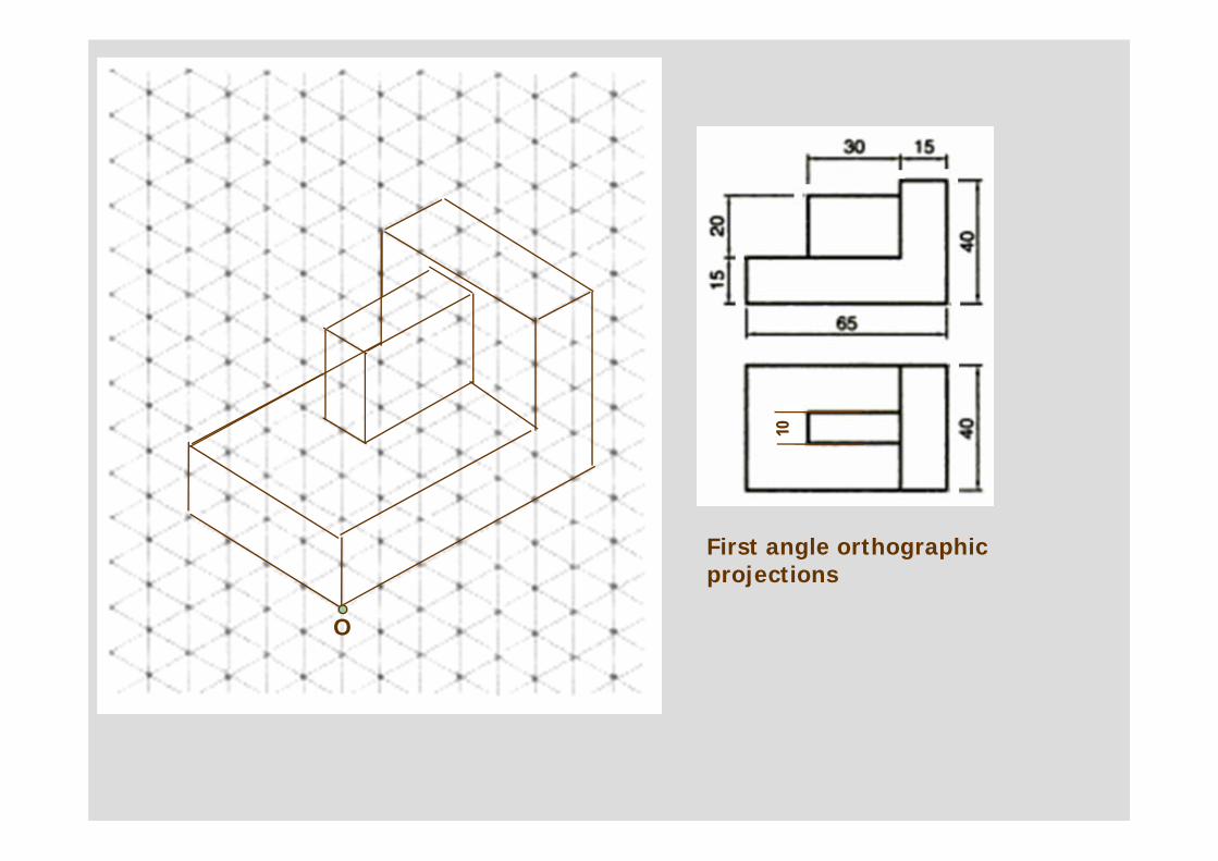
First angle orthographic projections
O
10
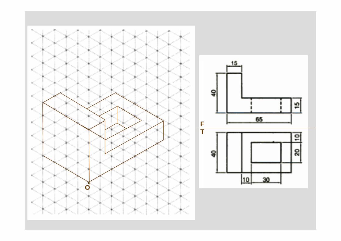
O
FT
x y
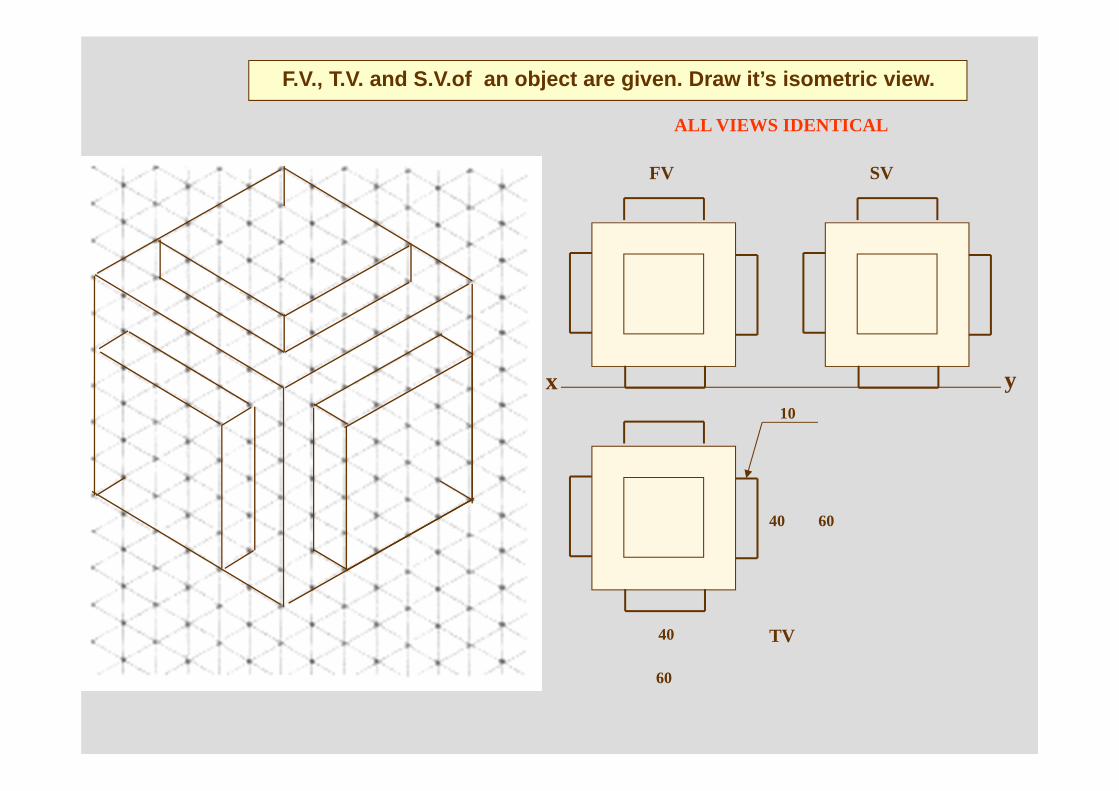
FV SV
TV
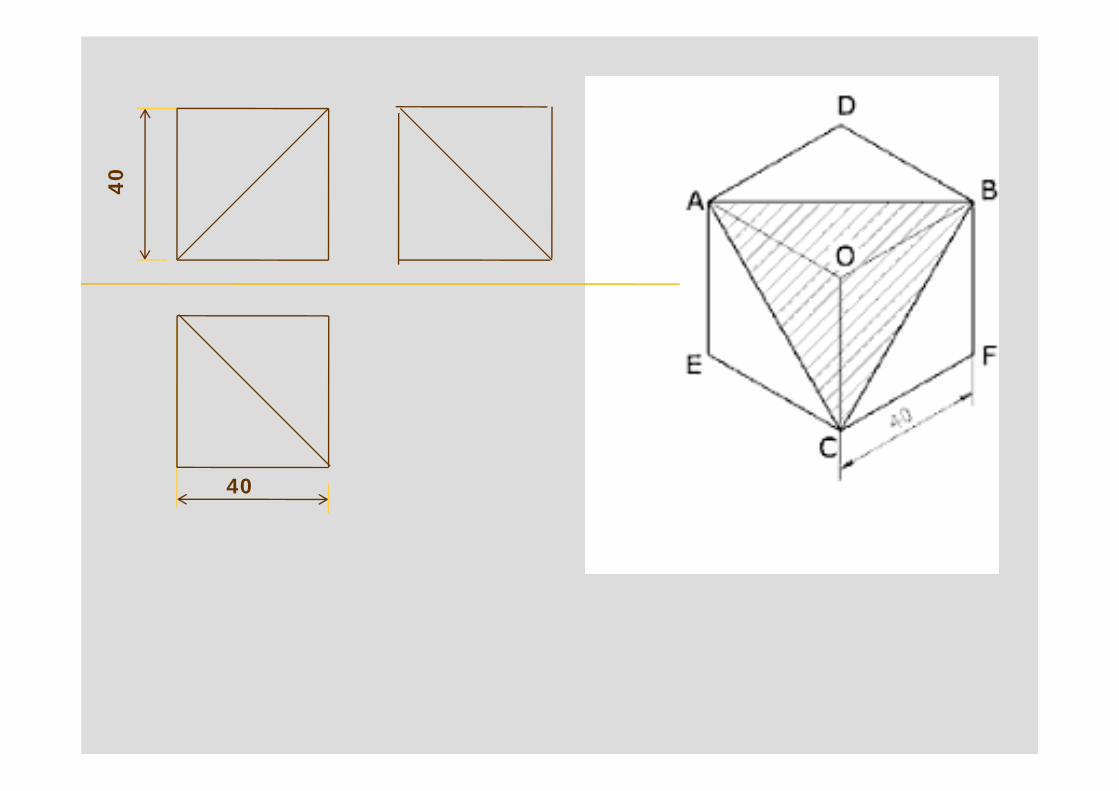
ALL VIEWS IDENTICAL
40 60
60
40
10
F.V., T.V. and S.V.of an object are given. Draw it’s isometric view.
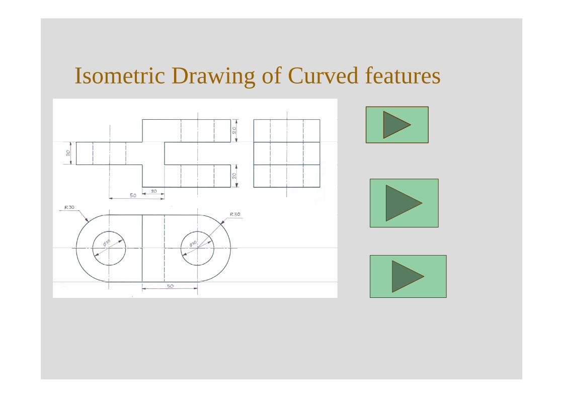
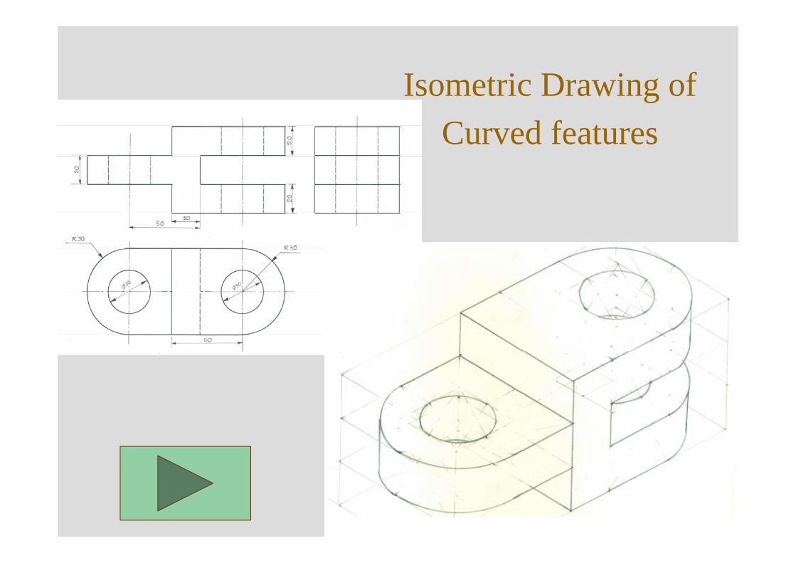
Isometric Drawing of Curved features
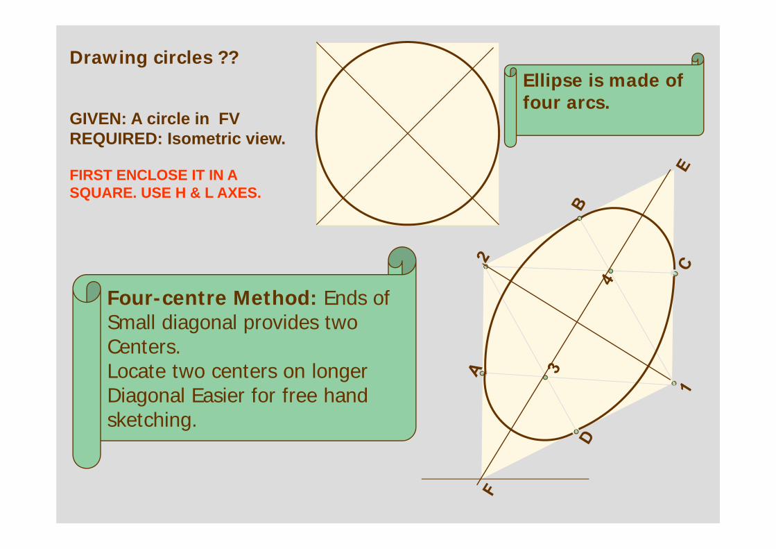
GIVEN: A circle in FVREQUIRED: Isometric view.
FIRST ENCLOSE IT IN A SQUARE. USE H & L AXES.
Four-centre Method: Ends of Small diagonal provides twoCenters. Locate two centers on longer Diagonal Easier for free hand sketching.
Ellipse is made of four arcs.
Drawing circles ??
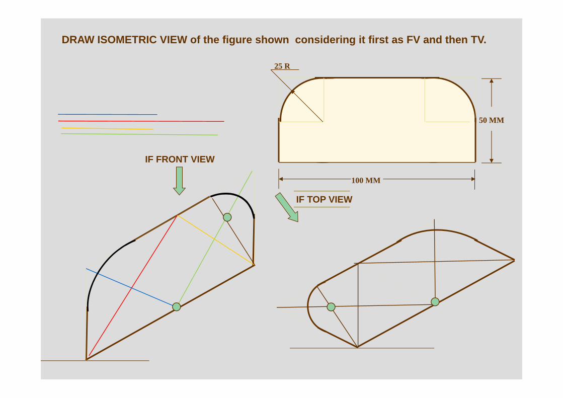
25 R
100 MM
50 MM
IF TOP VIEW
IF FRONT VIEW
DRAW ISOMETRIC VIEW of the figure shown considering it first as FV and then TV.
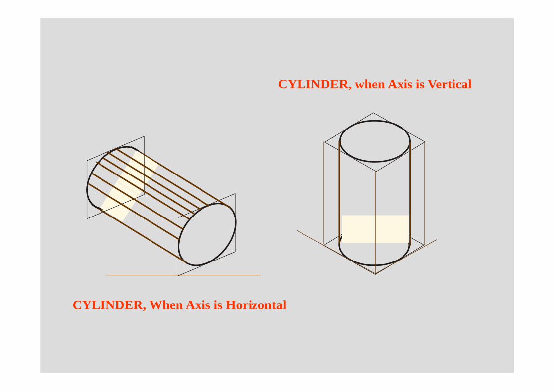
CYLINDER, When Axis is Horizontal
CYLINDER, when Axis is Vertical
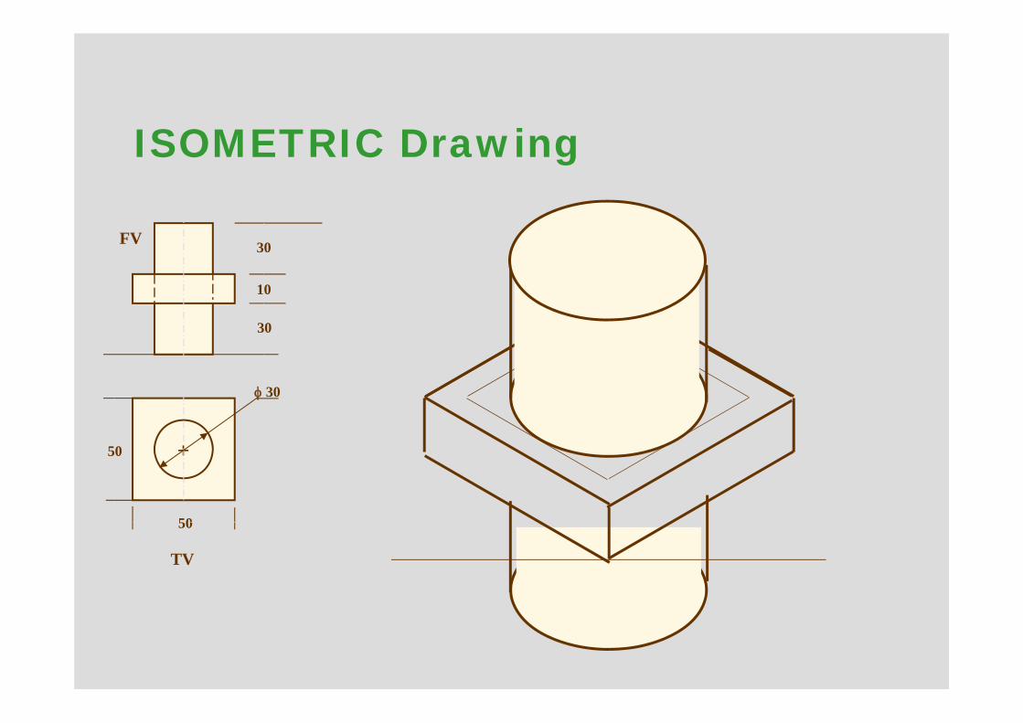
50
50
φ 30
30
10
30
+
FV
TV
ISOMETRIC Drawing
O
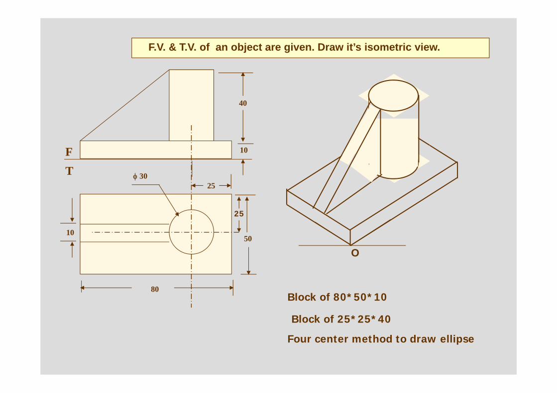
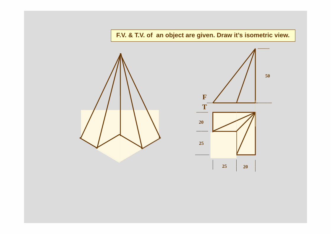
F.V. & T.V. of an object are given. Draw it’s isometric view.
40
10
50
80
10
φ 3025
FT
25
Block of 80*50*10
Block of 25*25*40
Four center method to draw ellipse
O
FV
TV
X YO
40
10
25
25
30 R
10
100103010
R 10
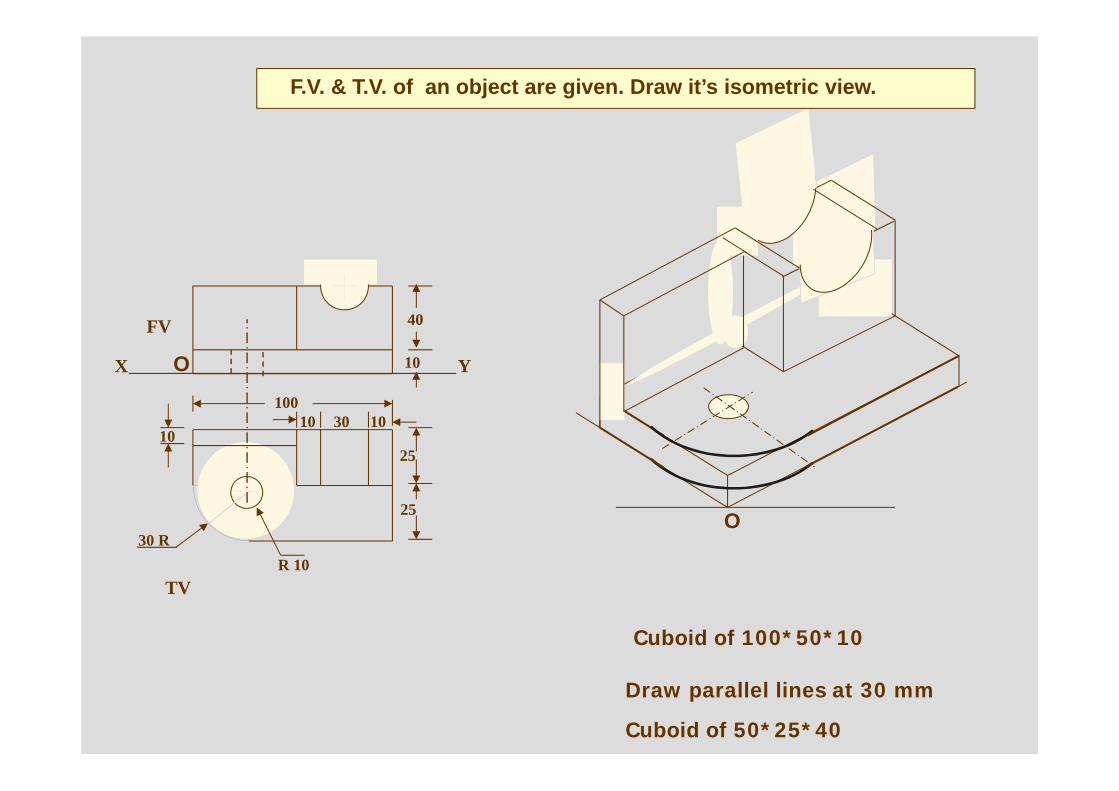
F.V. & T.V. of an object are given. Draw it’s isometric view.
Cuboid of 100*50*10
Draw parallel lines at 30 mm
Cuboid of 50*25*40
Isometric Drawing of Curved features
O
O10
10
30
10
30
4020
80
30
F
T
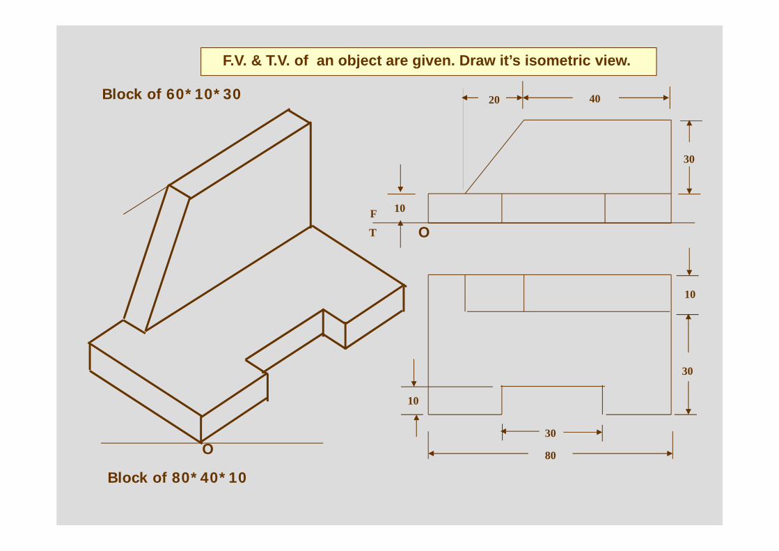
F.V. & T.V. of an object are given. Draw it’s isometric view.
Block of 80*40*10
Block of 60*10*30
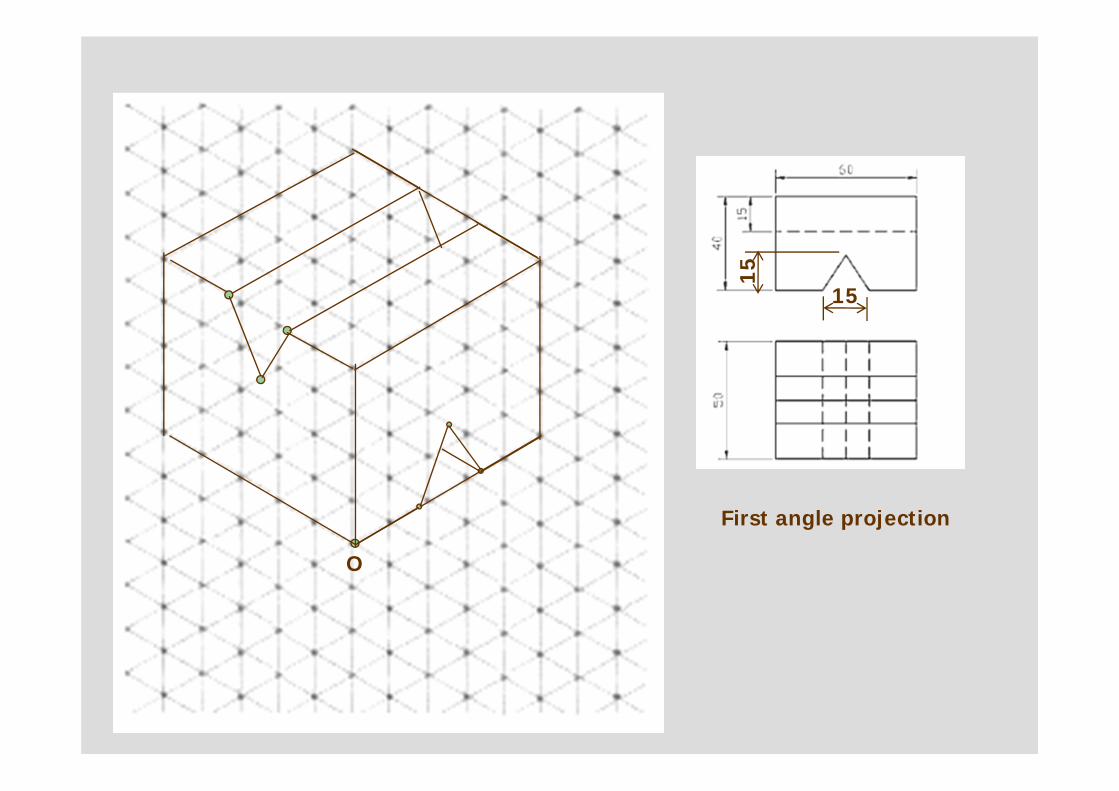
First angle projection
O
15
15
O
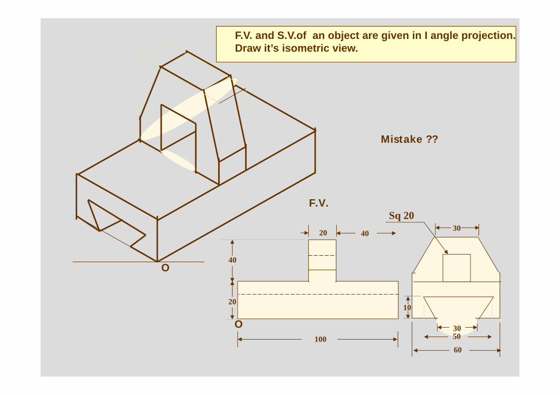
F.V. and S.V.of an object are given in I angle projection. Draw it’s isometric view.
Sq 20
O
20
2010
30
60
30
40
100 50
40
F.V.
Mistake ??
40
40
FT
50
20
25
25 20
F.V. & T.V. of an object are given. Draw it’s isometric view.
LSV
Y
25
25
1050
FV
X
10 10
15O
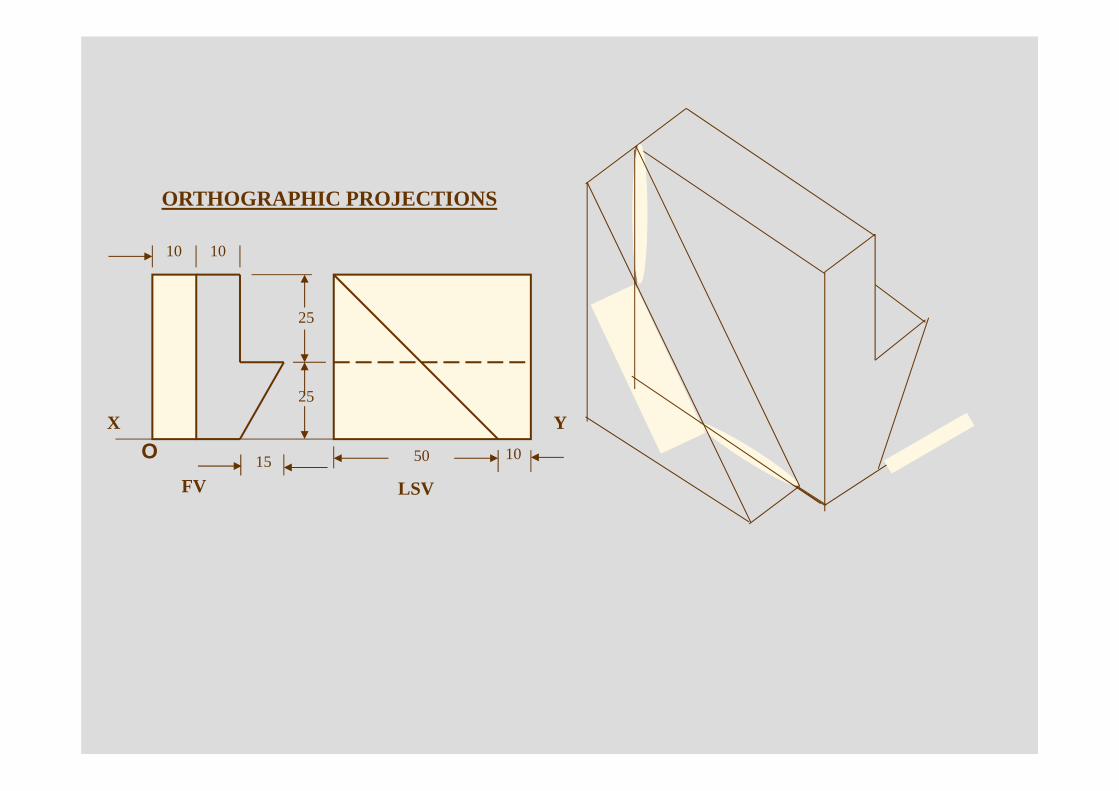
ORTHOGRAPHIC PROJECTIONS
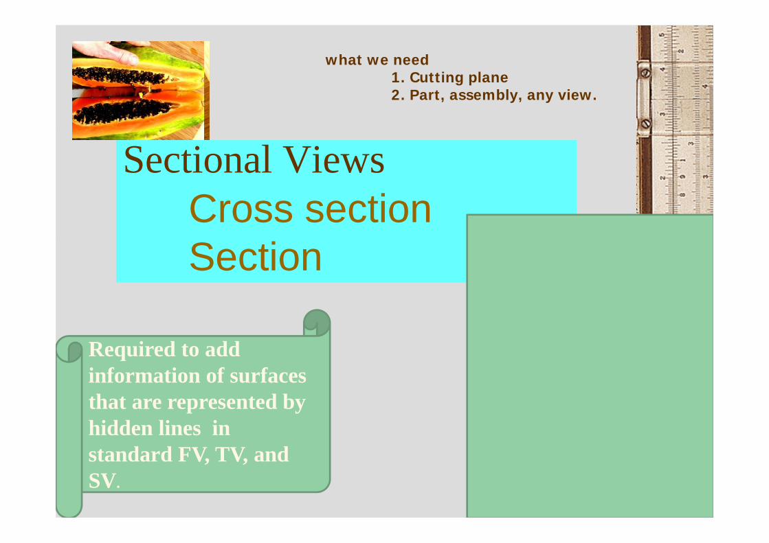
Sectional Views
79
Required to add information of surfaces that are represented by hidden lines in standard FV, TV, and SV.
what we need1. Cutting plane2. Part, assembly, any view.
Cross sectionSection
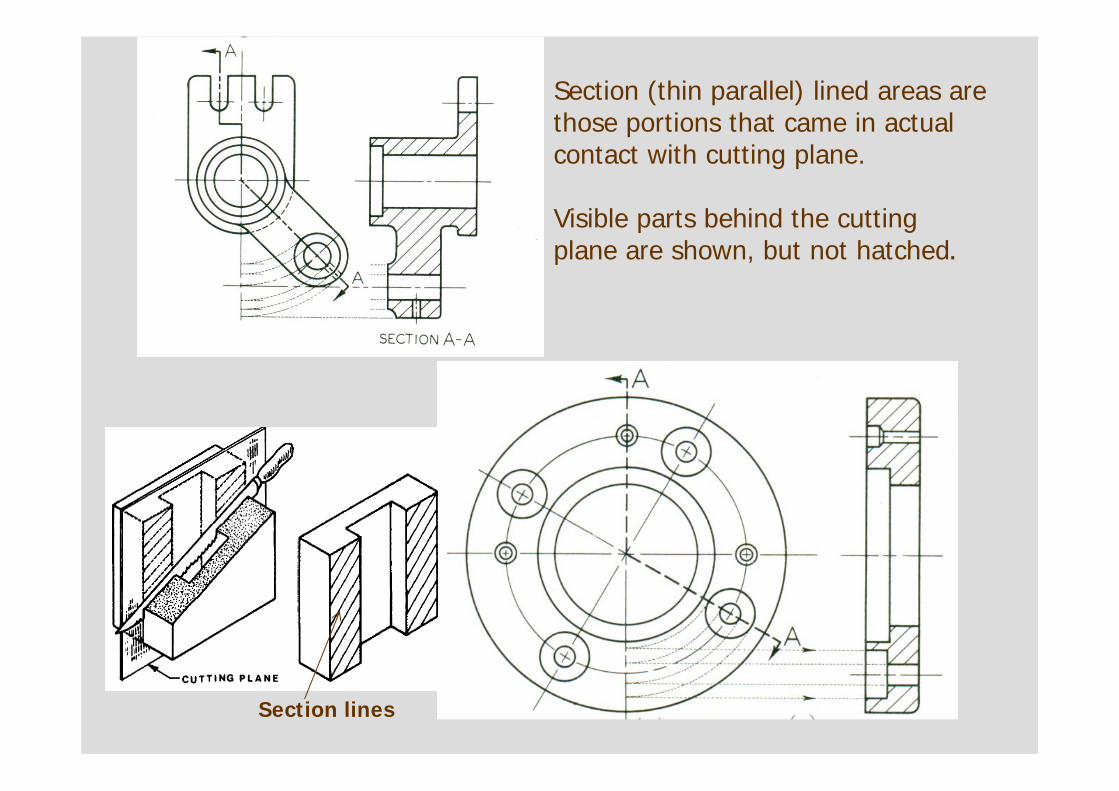
Section (thin parallel) lined areas are those portions that came in actual contact with cutting plane.
Visible parts behind the cutting plane are shown, but not hatched.
Section lines
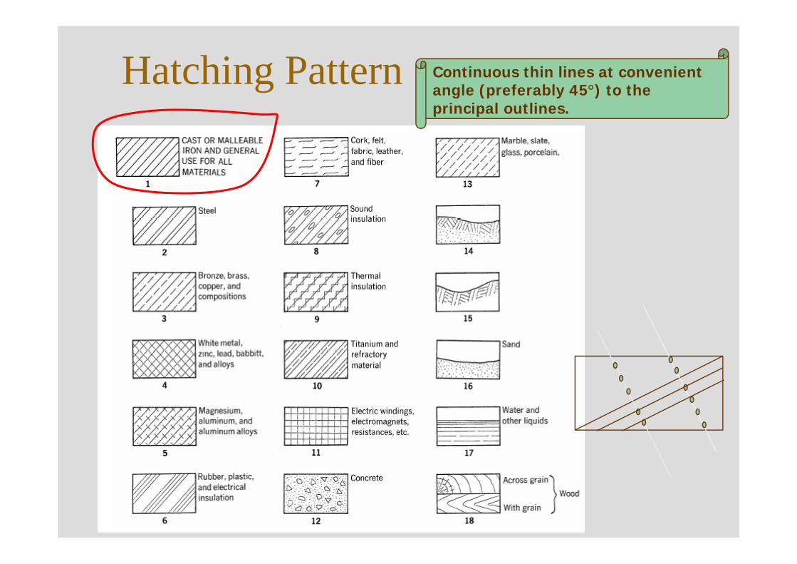
Hatching Pattern Continuous thin lines at convenient angle (preferably 45°) to the principal outlines.
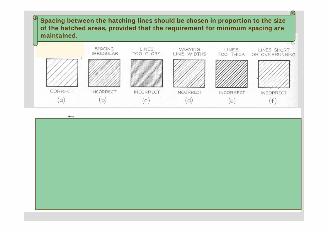
Common MistakesSpacing between the hatching lines should be chosen in proportion to the size of the hatched areas, provided that the requirement for minimum spacing are maintained.
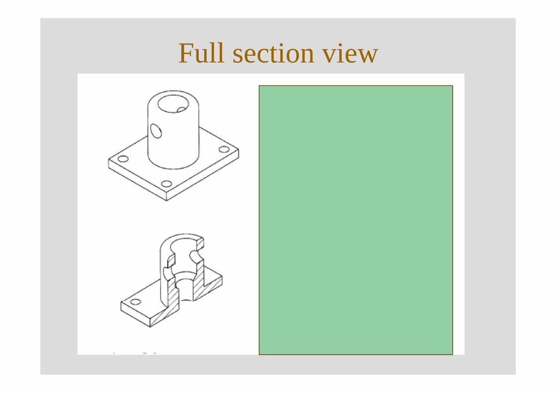
Full section view
NOTES
84
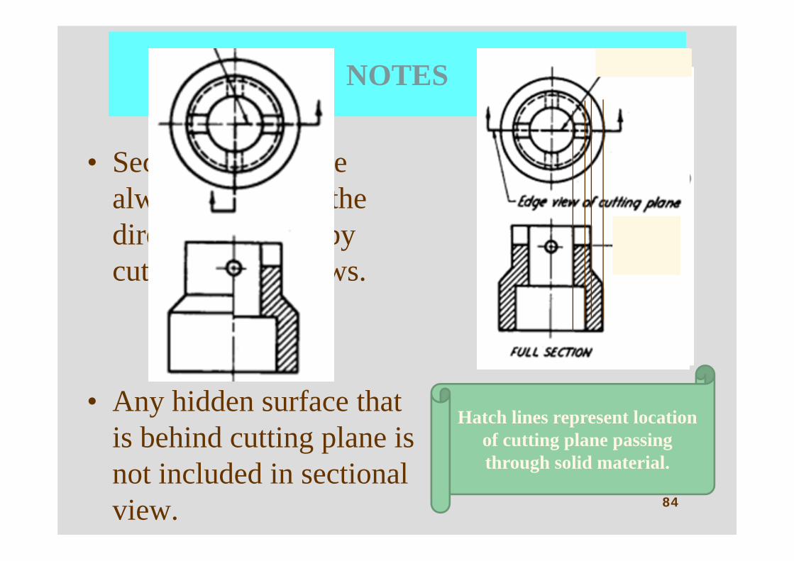
• Sectional views are always viewed in the direction defined by cutting plane arrows.
• Any hidden surface that is behind cutting plane is not included in sectional view.
Hatch lines represent location of cutting plane passing through solid material.
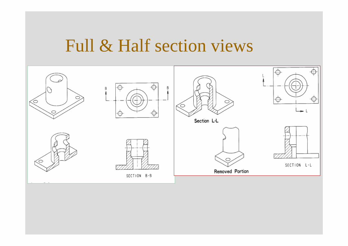
Full & Half section views
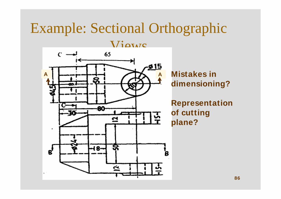
Example: Sectional Orthographic Views
86
AA Mistakes in dimensioning?
Representation of cutting plane?
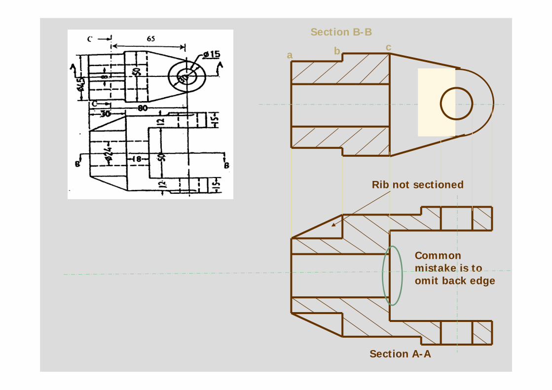
Section B-B
Section A-A
Rib not sectioned
a b c
Common mistake is to omit back edge
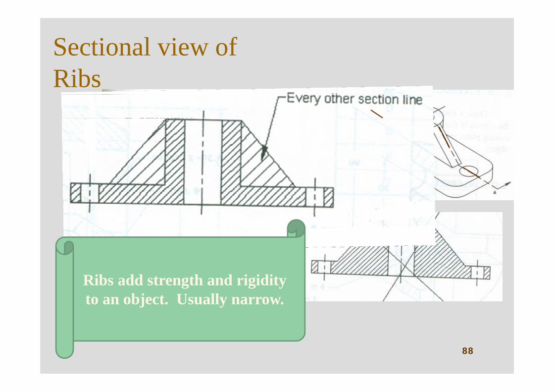
Sectional view of Ribs
88
Ribs add strength and rigidity to an object. Usually narrow.
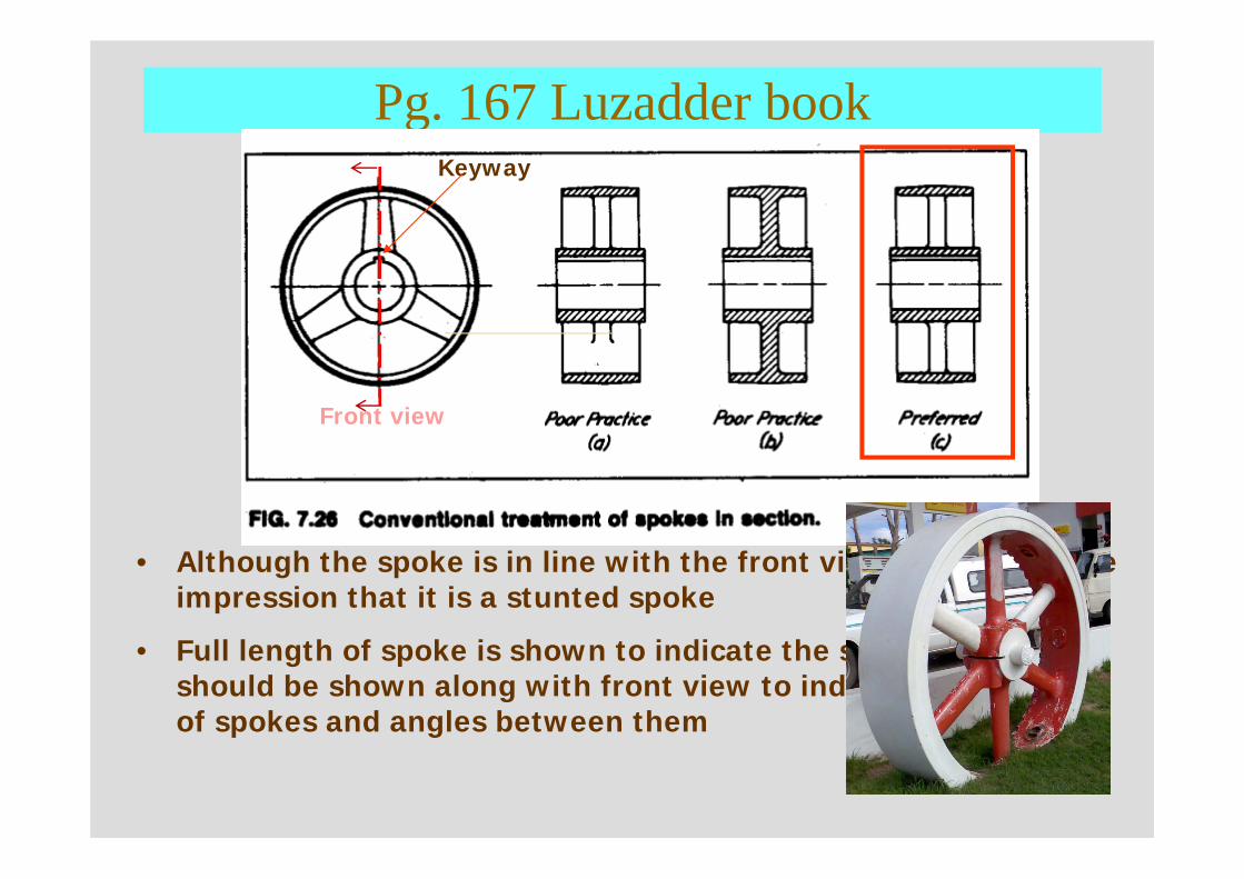
Pg. 167 Luzadder book
89
• Although the spoke is in line with the front view, it can give the impression that it is a stunted spoke
• Full length of spoke is shown to indicate the structure. It should be shown along with front view to indicate the number of spokes and angles between them
Front view
Keyway
90
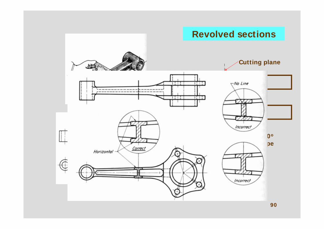
Revolved sections
Section rotated 90o
so that exact shape can be viewed
Cutting plane
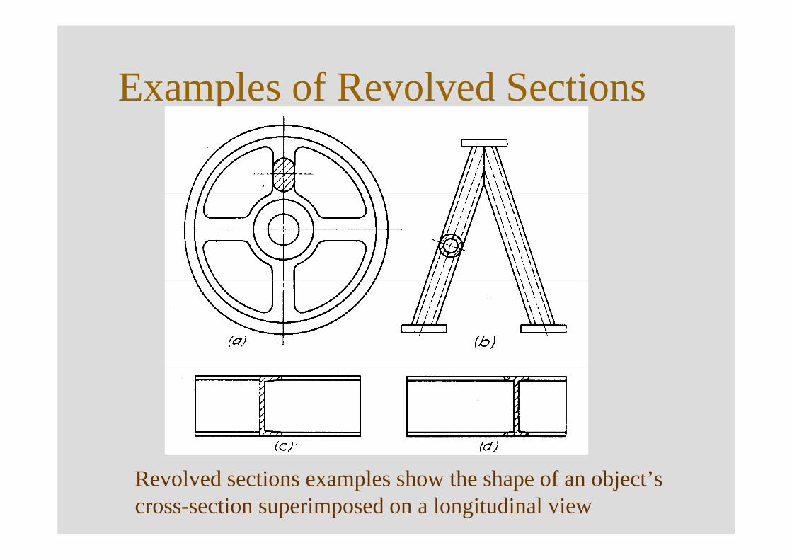
Examples of Revolved Sections
Revolved sections examples show the shape of an object’s cross-section superimposed on a longitudinal view
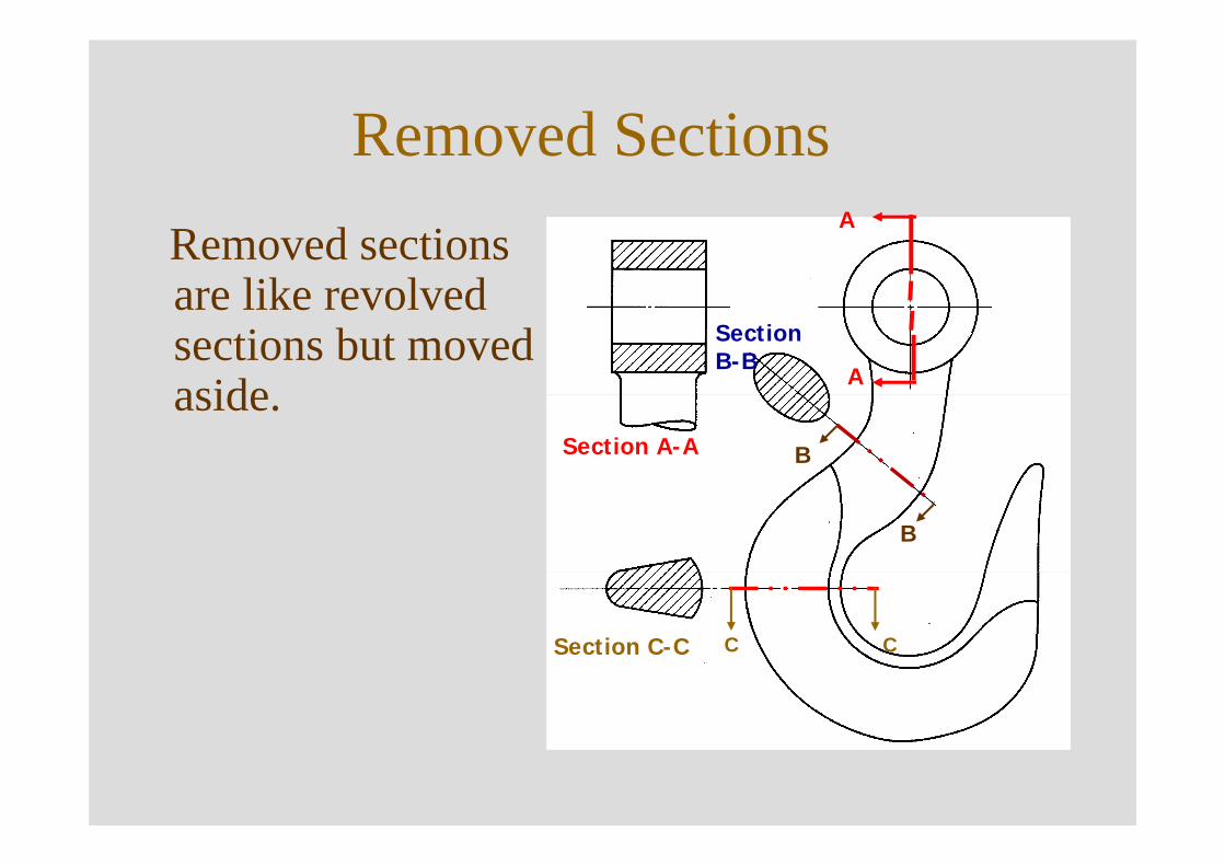
Removed SectionsRemoved sections are like revolved sections but moved aside.
A
A
Section A-A
C CSection C-C
B
B
Section B-B
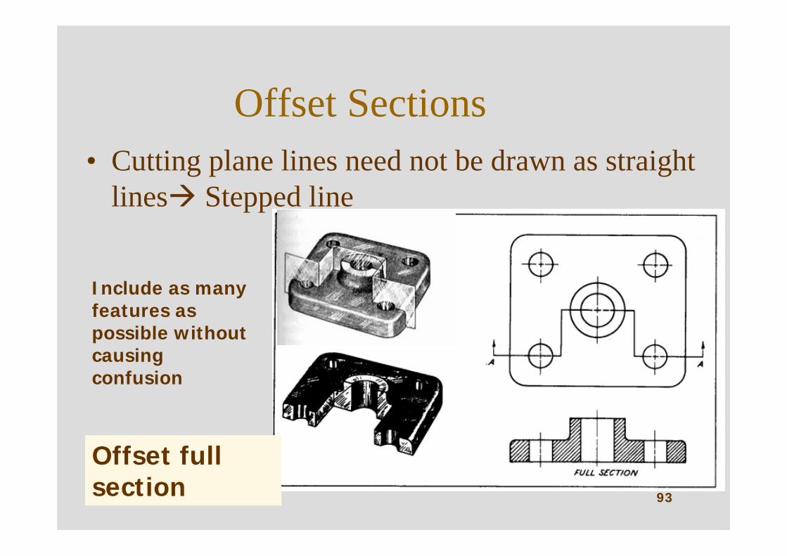
Offset Sections• Cutting plane lines need not be drawn as straight
lines Stepped line
93
Offset full section
Include as many features as possible without causing confusion

94
Countersunk hole
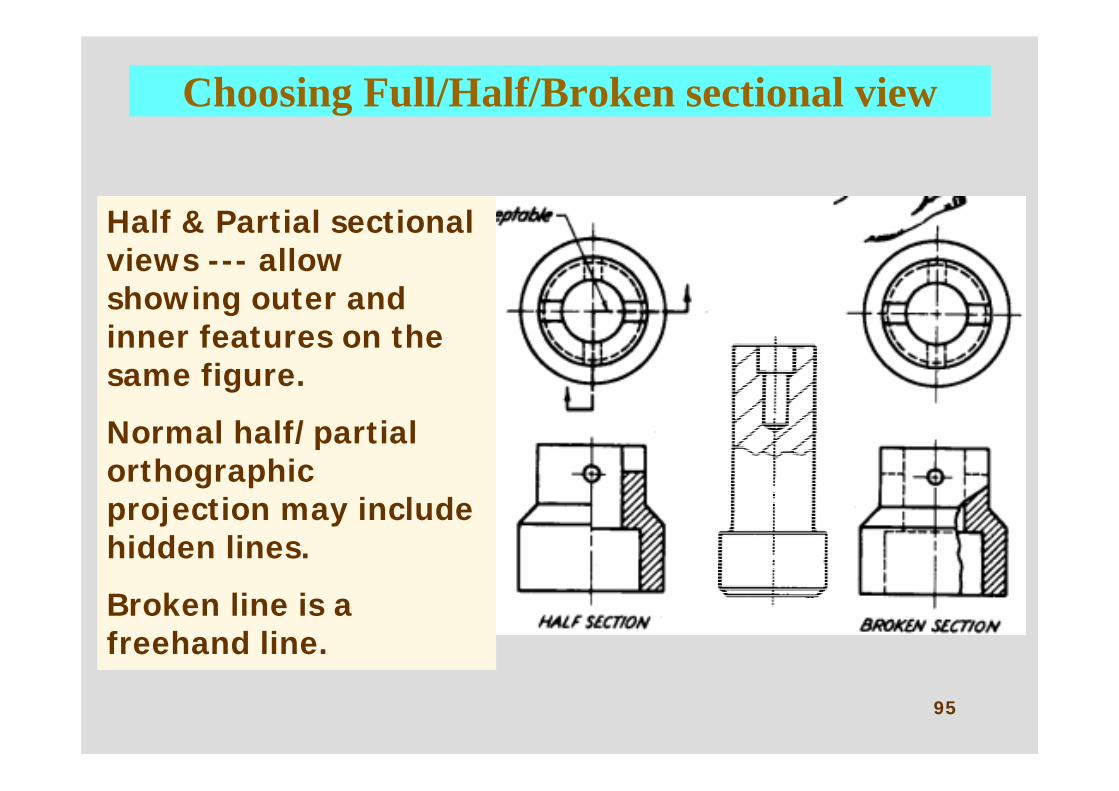
Choosing Full/Half/Broken sectional view
95
Half & Partial sectional views --- allow showing outer and inner features on the same figure.
Normal half/partial orthographic projection may include hidden lines.
Broken line is a freehand line.
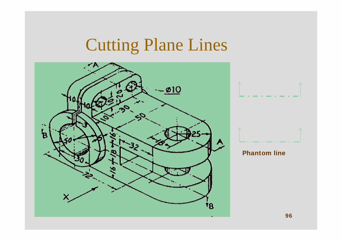
Cutting Plane Lines
96
Phantom line
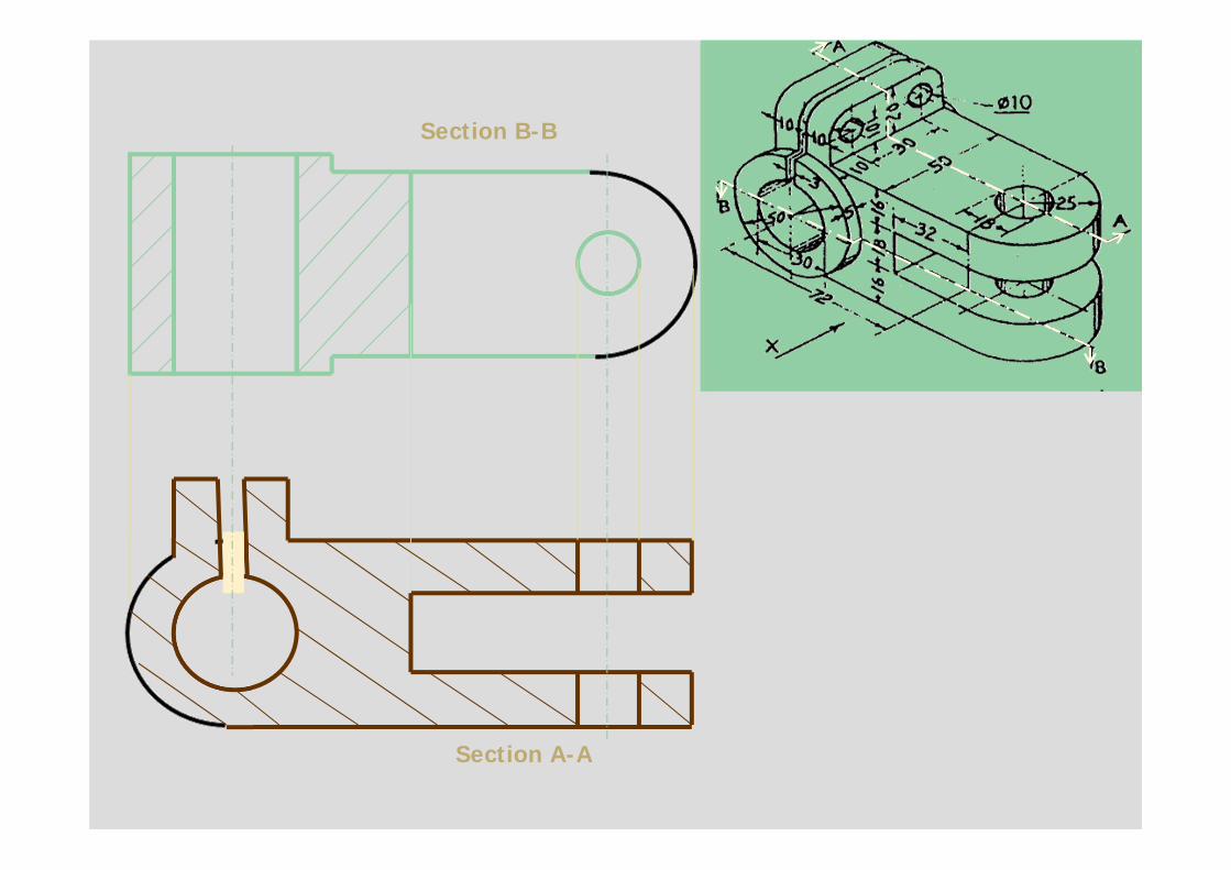
Section B-B
Section A-A
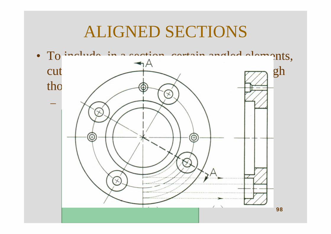
ALIGNED SECTIONS• To include, in a section, certain angled elements,
cutting plane may be bent so as to pass through those features.– Plane & feature are aligned into original plane.
98
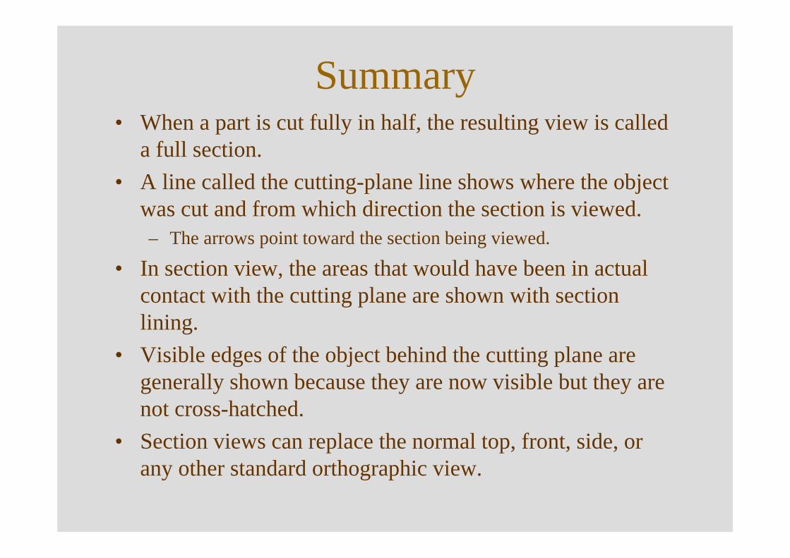
Summary• When a part is cut fully in half, the resulting view is called
a full section.• A line called the cutting-plane line shows where the object
was cut and from which direction the section is viewed.– The arrows point toward the section being viewed.
• In section view, the areas that would have been in actual contact with the cutting plane are shown with section lining.
• Visible edges of the object behind the cutting plane are generally shown because they are now visible but they are not cross-hatched.
• Section views can replace the normal top, front, side, or any other standard orthographic view.
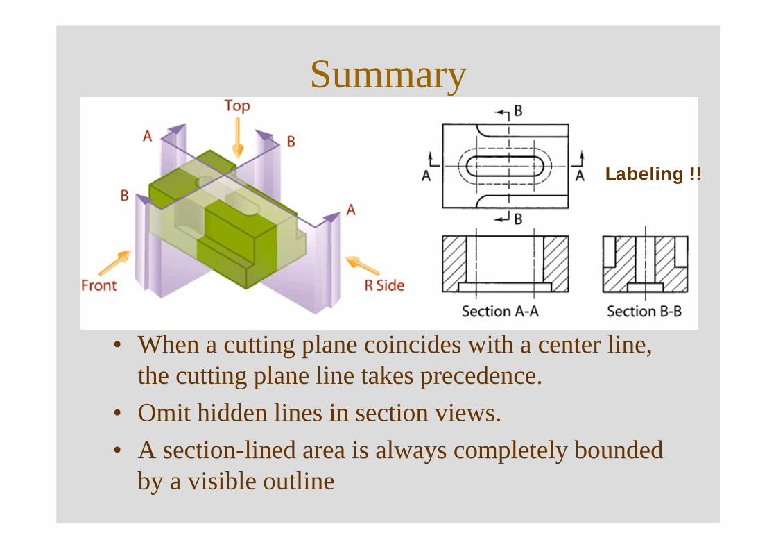
Summary
• When a cutting plane coincides with a center line, the cutting plane line takes precedence.
• Omit hidden lines in section views.• A section-lined area is always completely bounded
by a visible outline
Labeling !!
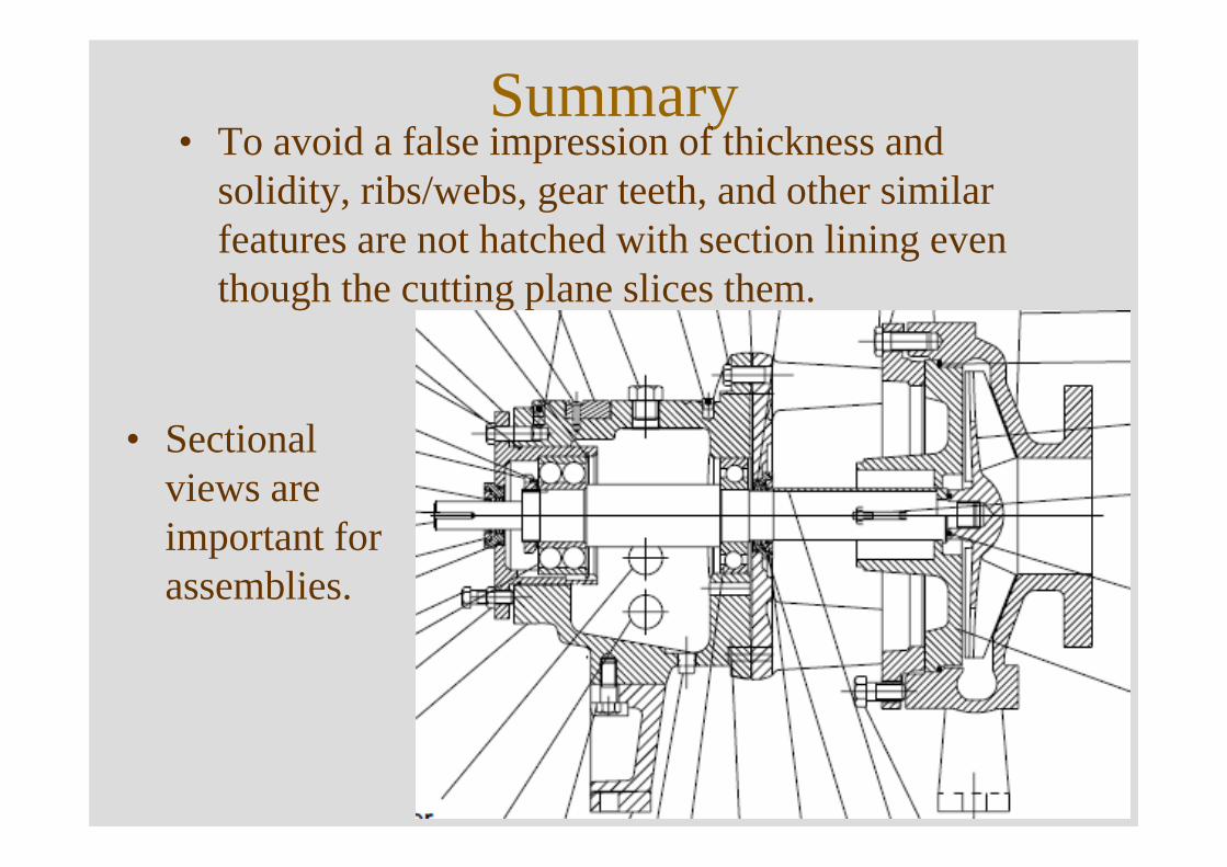
Summary• To avoid a false impression of thickness and
solidity, ribs/webs, gear teeth, and other similar features are not hatched with section lining even though the cutting plane slices them.
• Sectional views are important for assemblies.
102
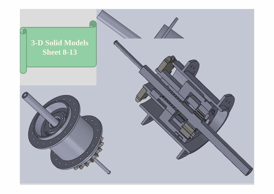
3-D Solid ModelsSheet 8-13
103
104
105
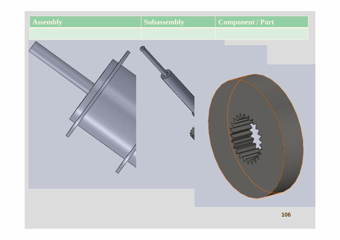
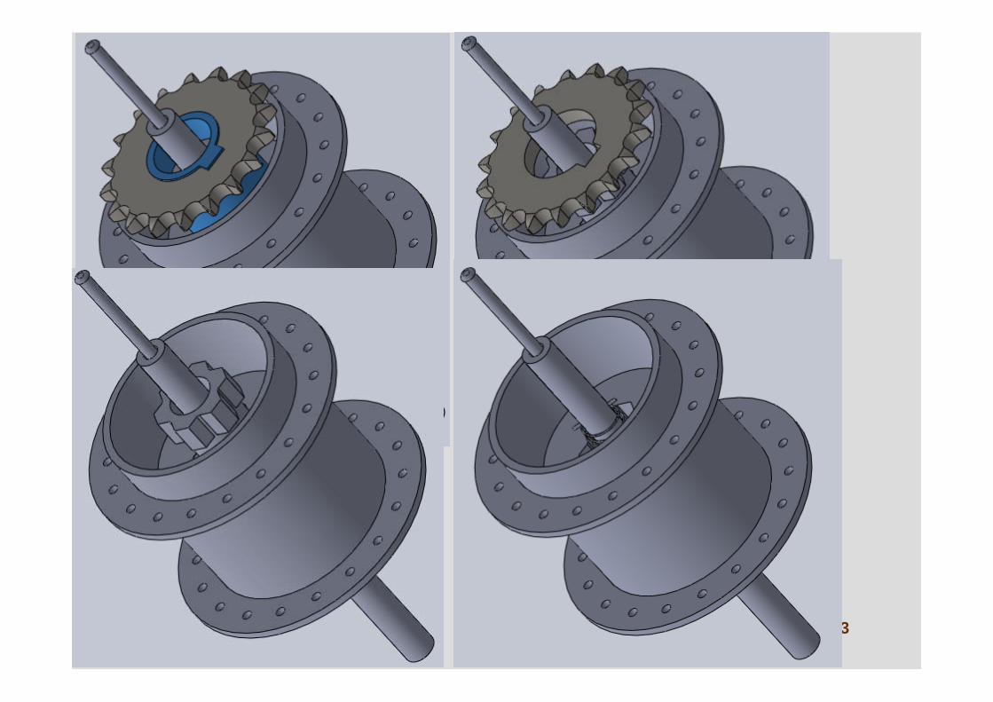
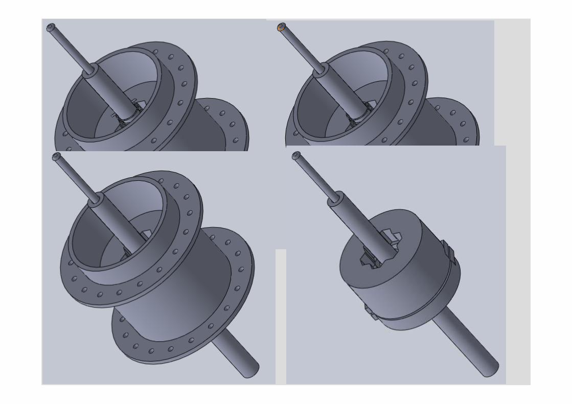
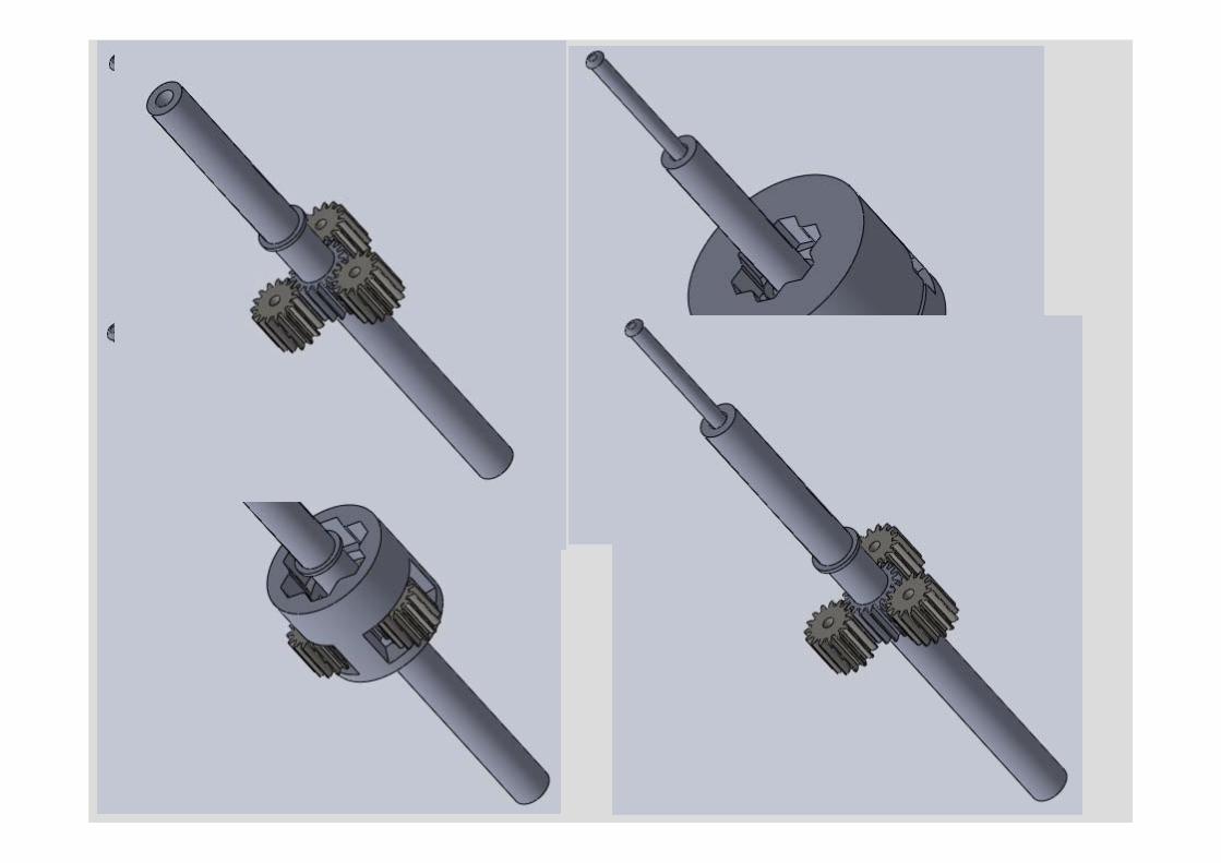
106
Assembly Subassembly Component / Part
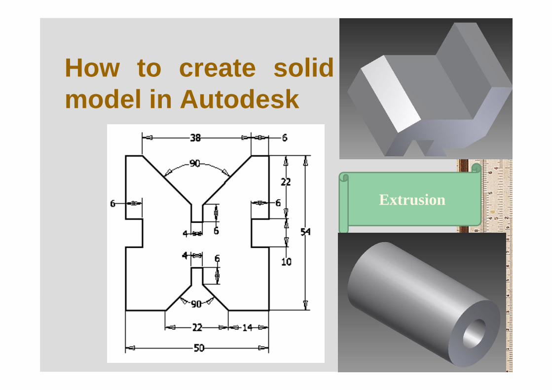
How to create solidmodel in Autodesk
Extrusion
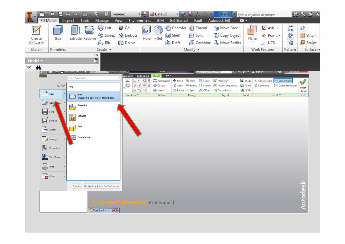
• Select New > New , to make the sketch
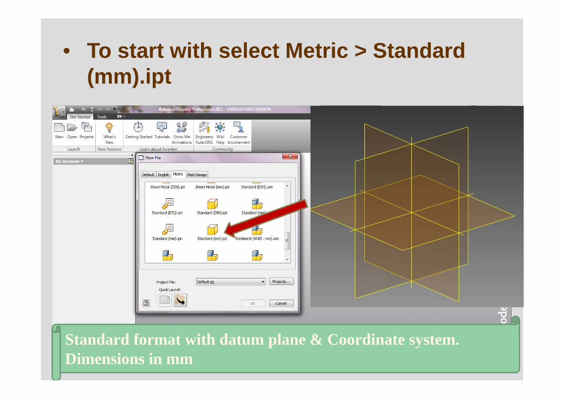
• To start with select Metric > Standard (mm).ipt
Standard format with datum plane & Coordinate system. Dimensions in mm
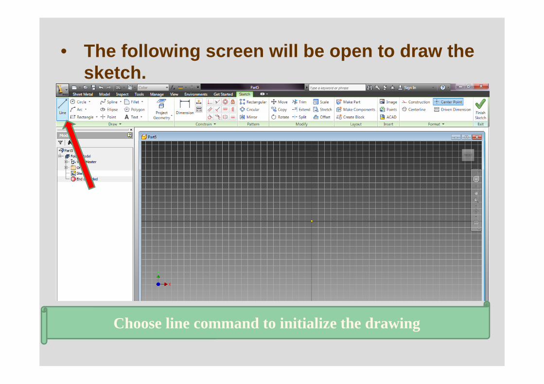
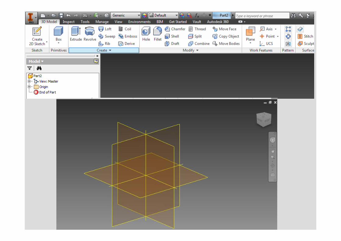
• The following screen will be open to draw the sketch.
Choose line command to initialize the drawing
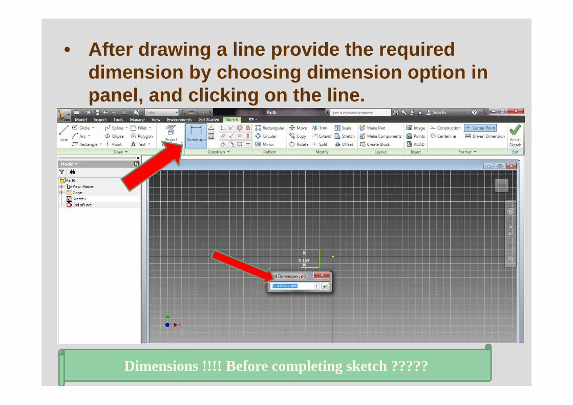
• After drawing a line provide the required dimension by choosing dimension option in panel, and clicking on the line.
Dimensions !!!! Before completing sketch ?????
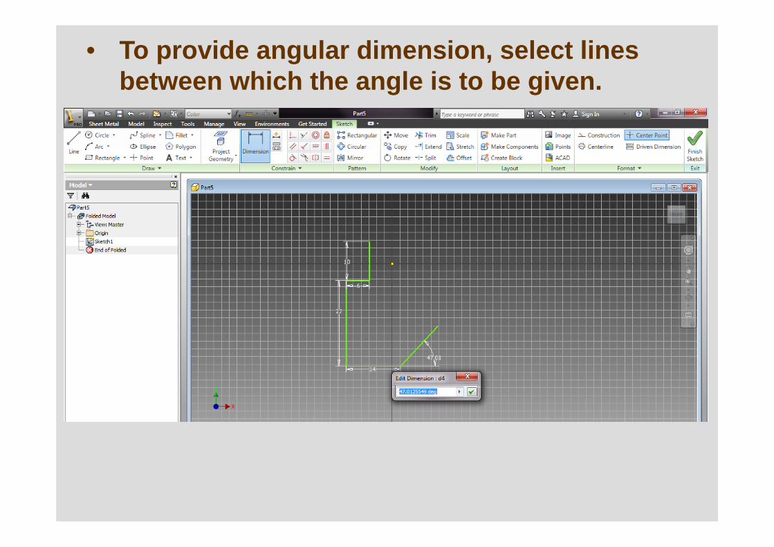
• To provide angular dimension, select lines between which the angle is to be given.
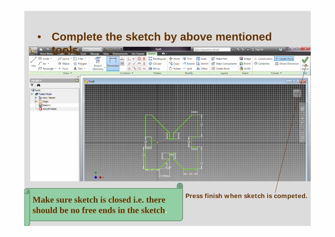
• Complete the sketch by above mentioned tools.
Press finish when sketch is competed.Make sure sketch is closed i.e. there should be no free ends in the sketch.
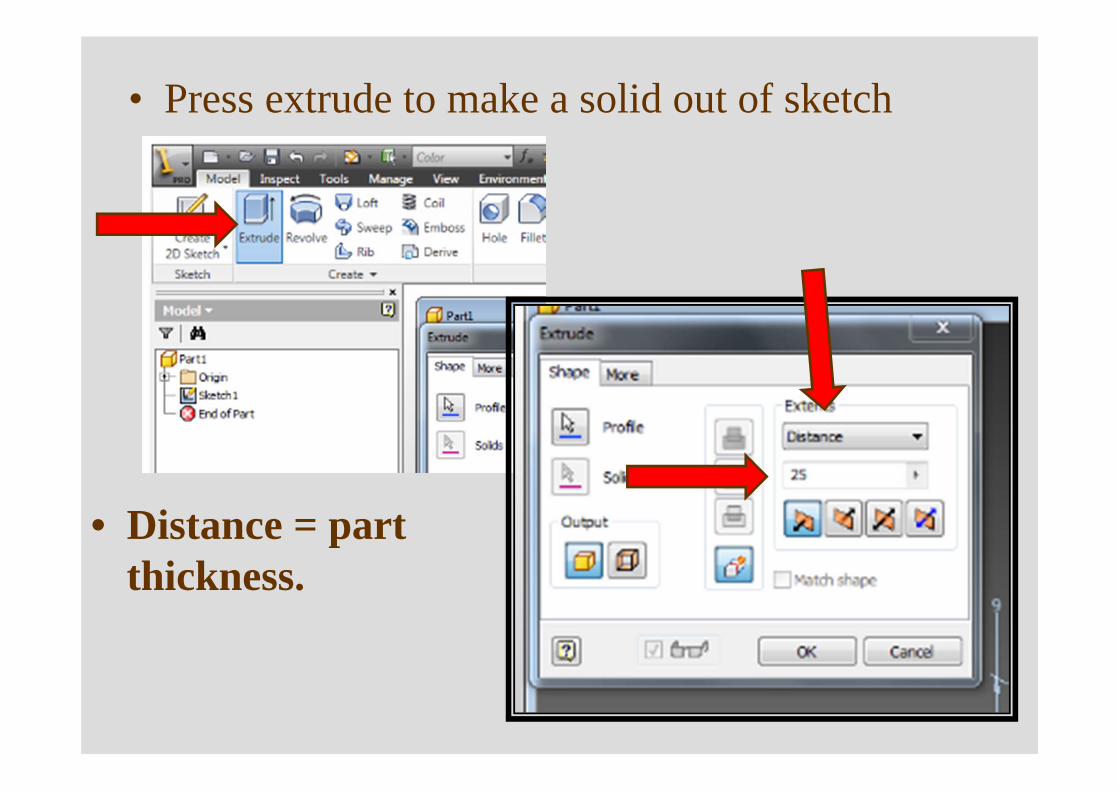
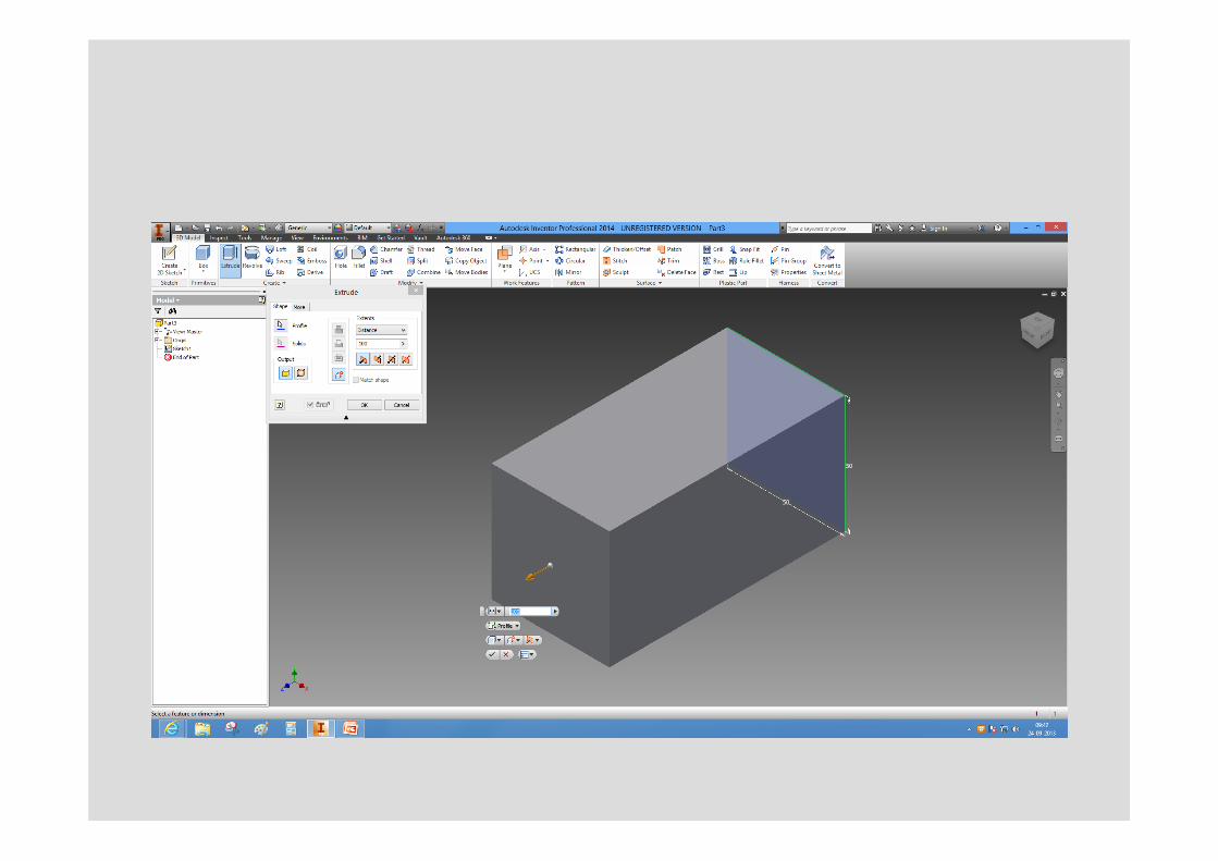
• Press extrude to make a solid out of sketch
• Distance = part thickness.
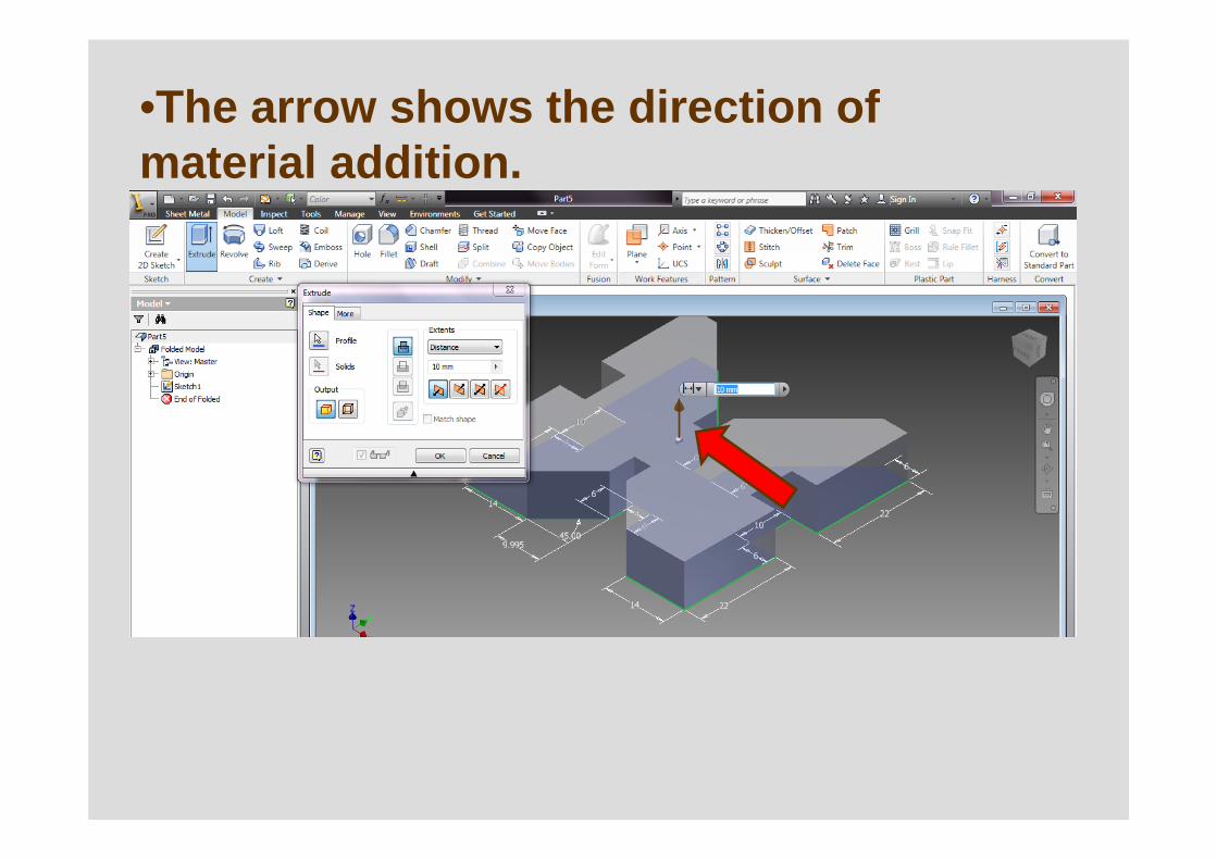
•The arrow shows the direction of material addition.
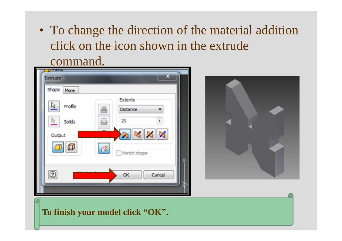
• To change the direction of the material addition click on the icon shown in the extrude command.
To finish your model click “OK”.
Software Autodesk Inventor Professional
• Available in CSC window machines (9am –9 pm).
• Students can download software from http://students.autodesk.com/?nd=download_center
• Register using email id and get license key.• Evaluation:
– Submit print-out of drawings. One page per question. • How do I make title block• Import (download) mep100.dwg format.
117
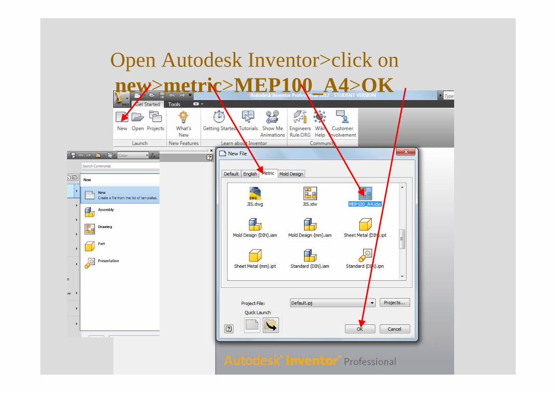
Open Autodesk Inventor>click on new>metric>MEP100_A4>OK
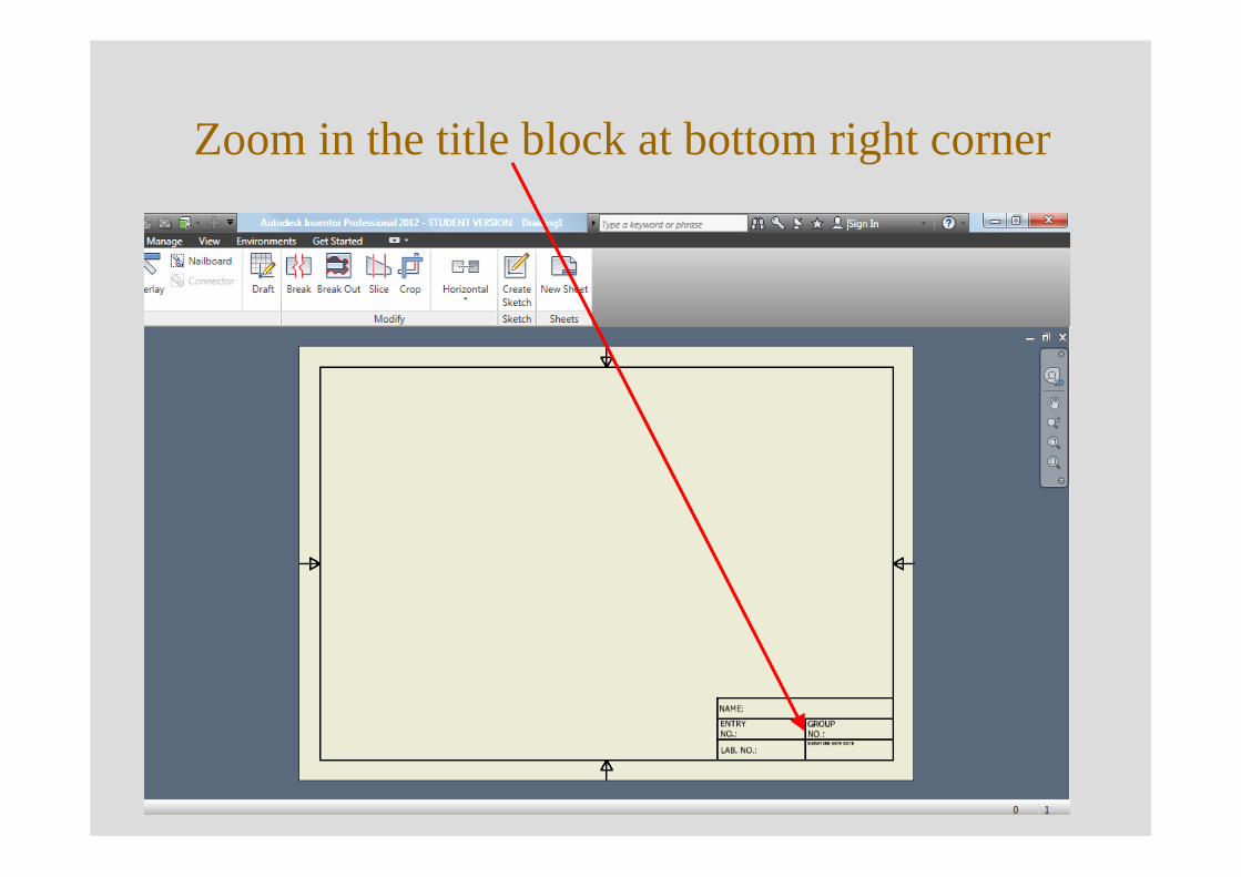
Zoom in the title block at bottom right corner
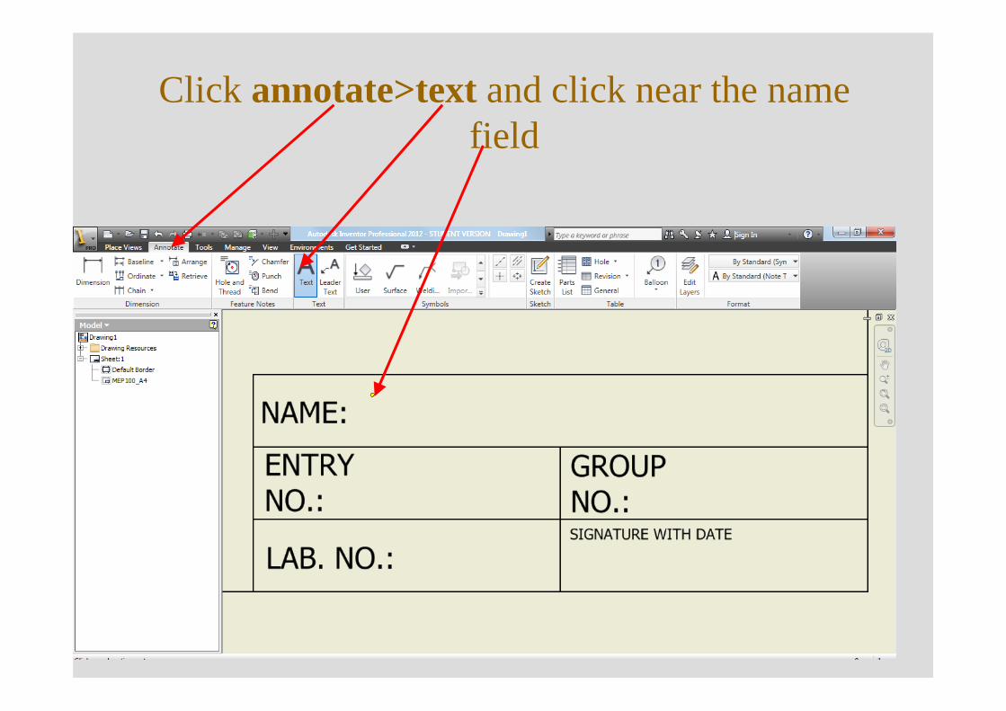
Click annotate>text and click near the name field
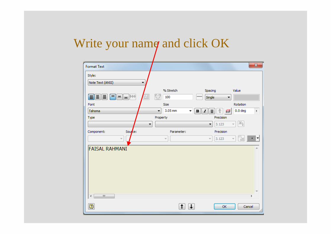
Write your name and click OK
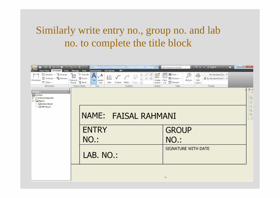
Similarly write entry no., group no. and lab no. to complete the title block
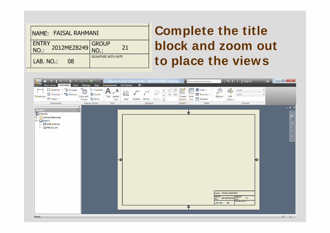
Complete the title block and zoom out to place the views
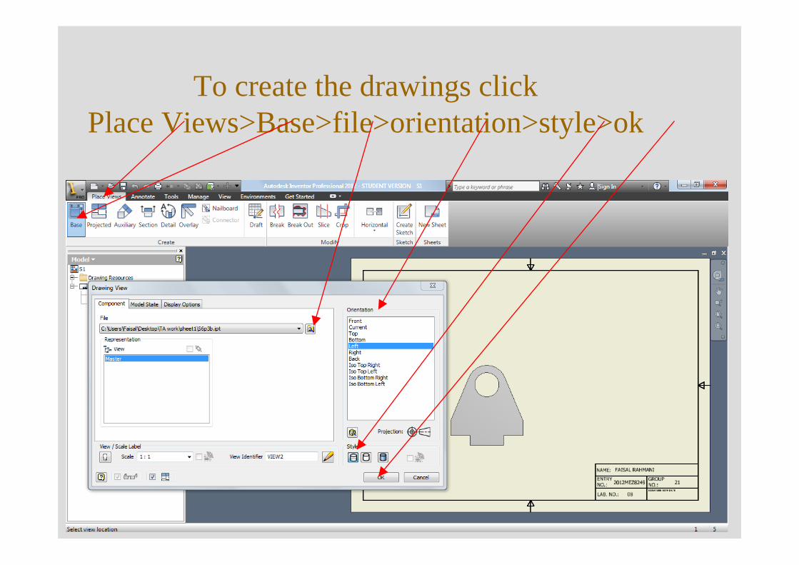
To create the drawings clickPlace Views>Base>file>orientation>style>ok
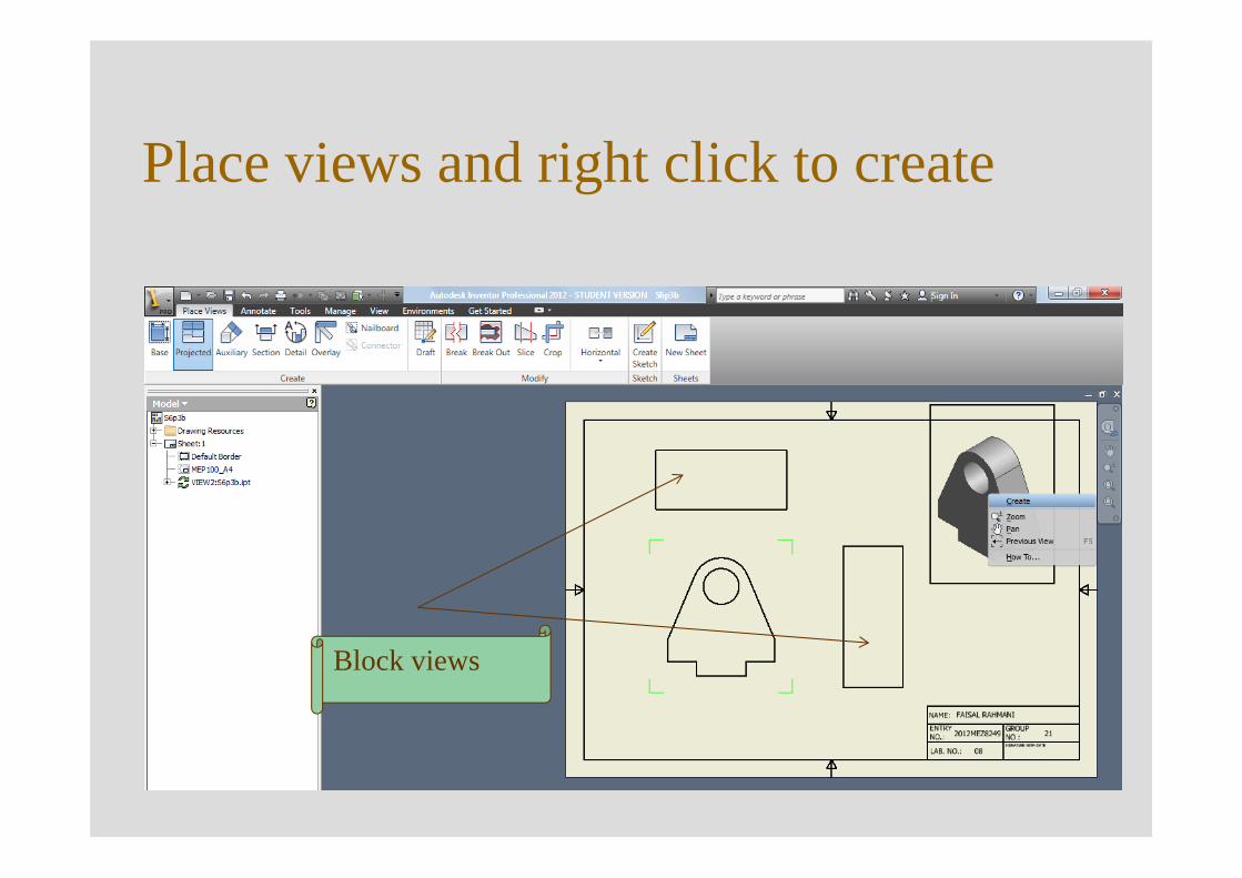
Place views and right click to create
Block views
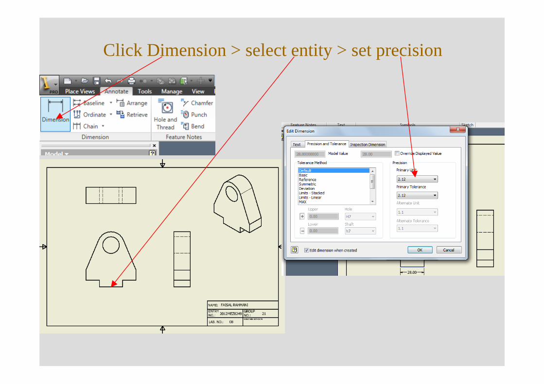
Click Dimension > select entity > set precision
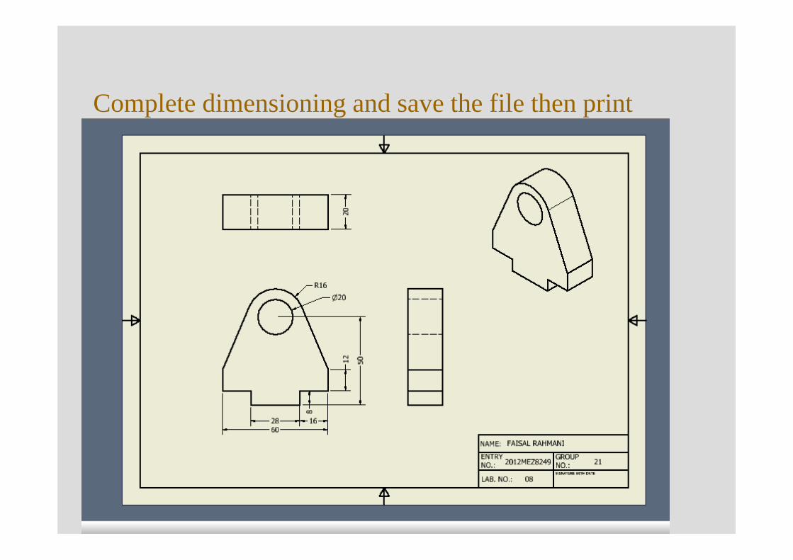
Complete dimensioning and save the file then print
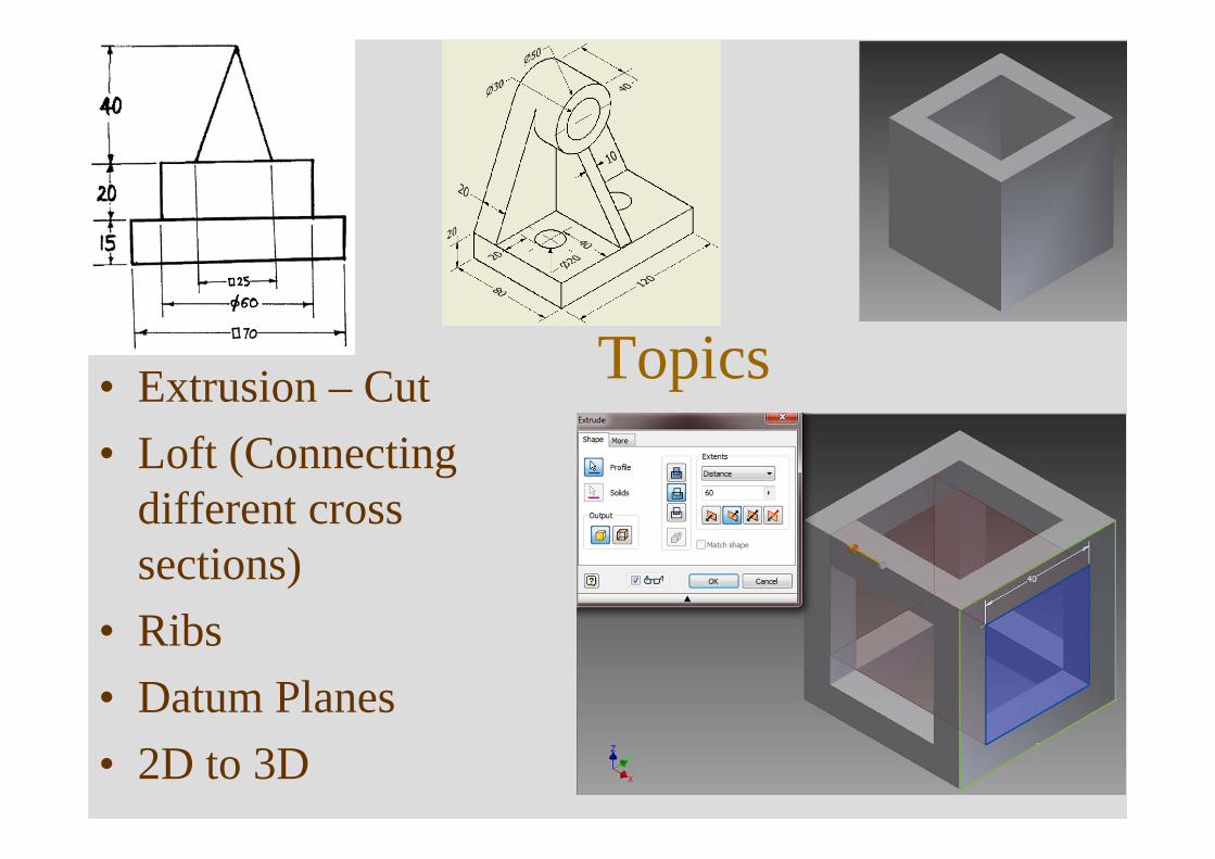
Topics• Extrusion – Cut• Loft (Connecting
different cross sections)
• Ribs• Datum Planes• 2D to 3D
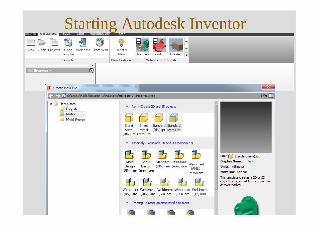
Starting Autodesk Inventor
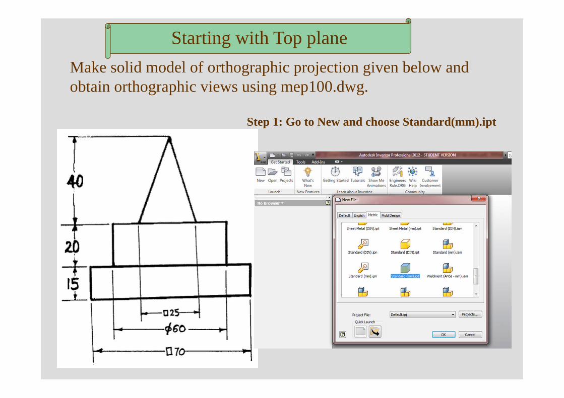
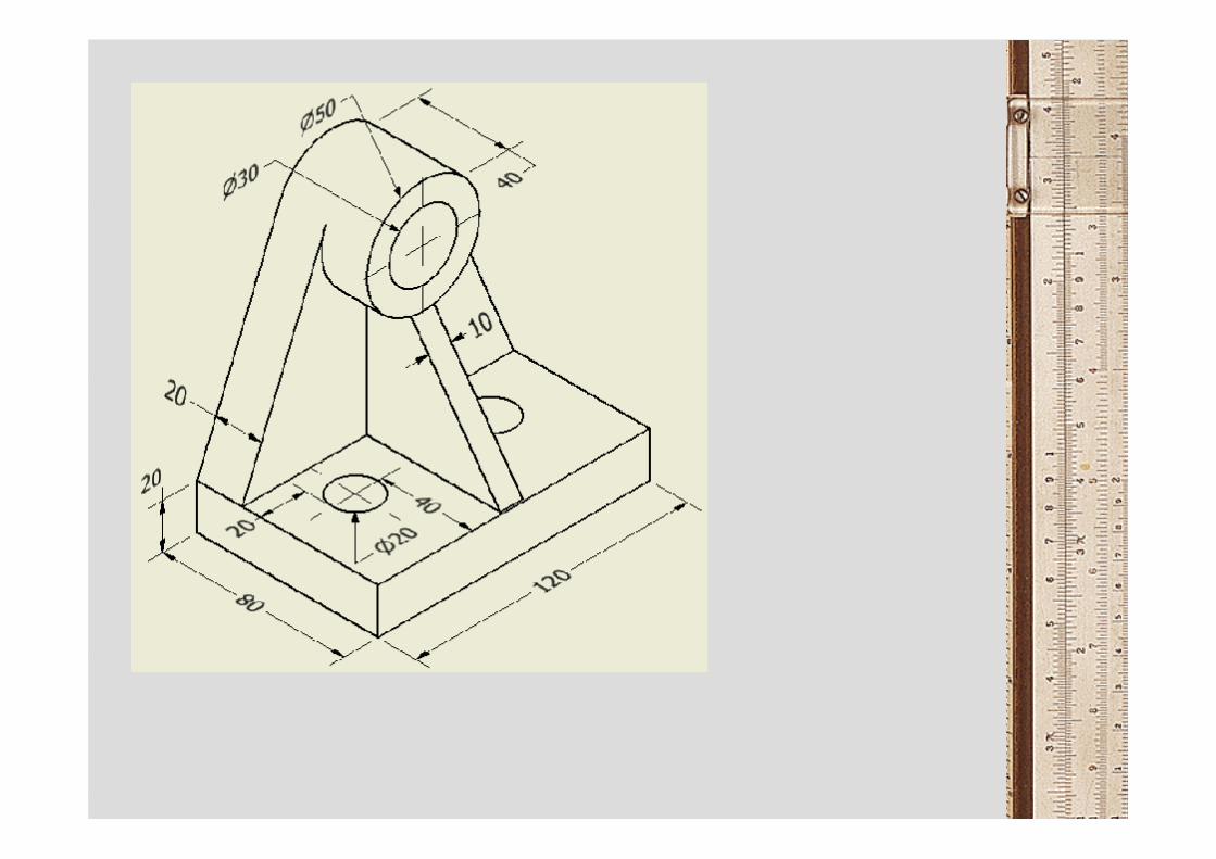
Make solid model of orthographic projection given below and obtain orthographic views using mep100.dwg.
Step 1: Go to New and choose Standard(mm).ipt
Starting with Top plane
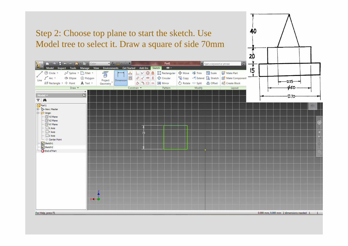
Step 2: Choose top plane to start the sketch. Use Model tree to select it. Draw a square of side 70mm
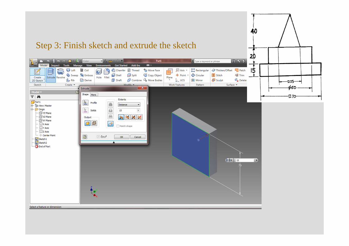
Step 3: Finish sketch and extrude the sketch
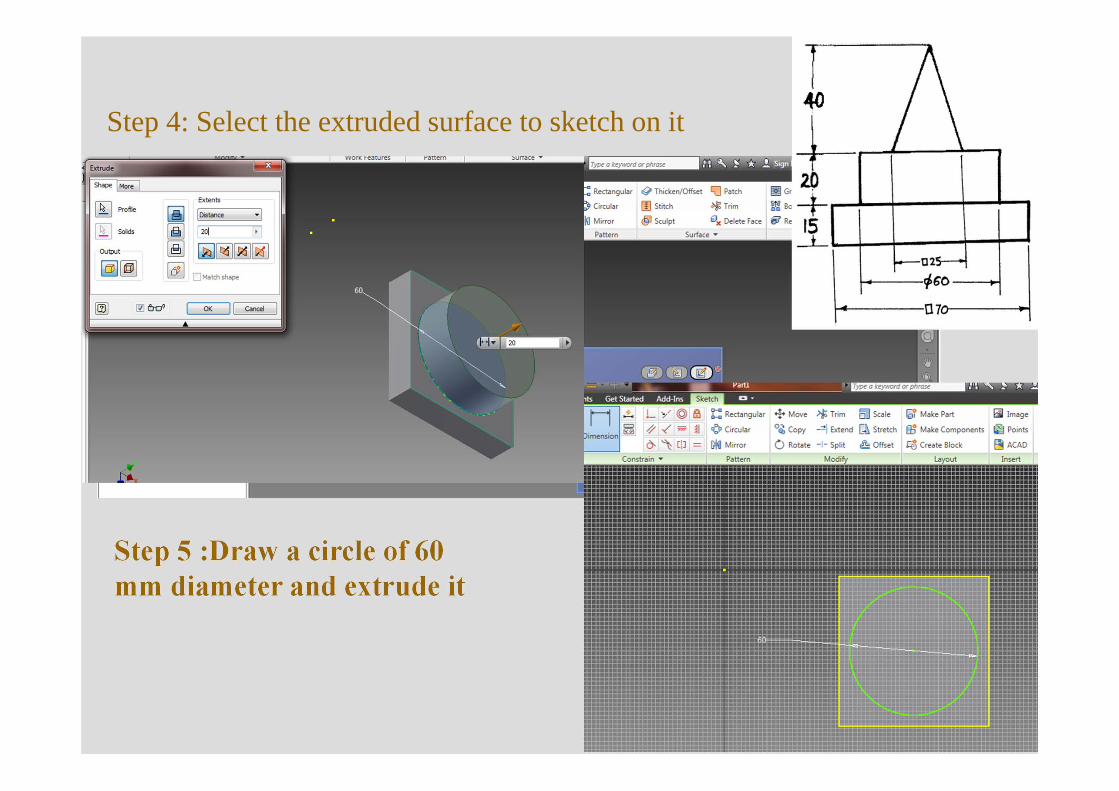
Step 4: Select the extruded surface to sketch on it
Step 5 :Draw a circle of 60 mm diameter and extrude it
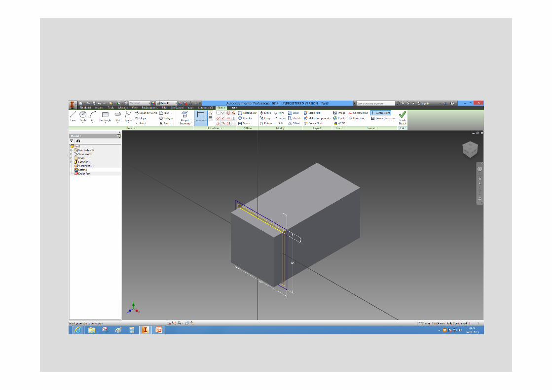
Step 6: Select the extruded surface to sketch a square of 25mm on it. Finish the sketch
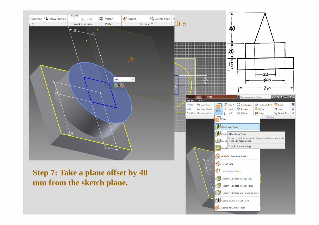
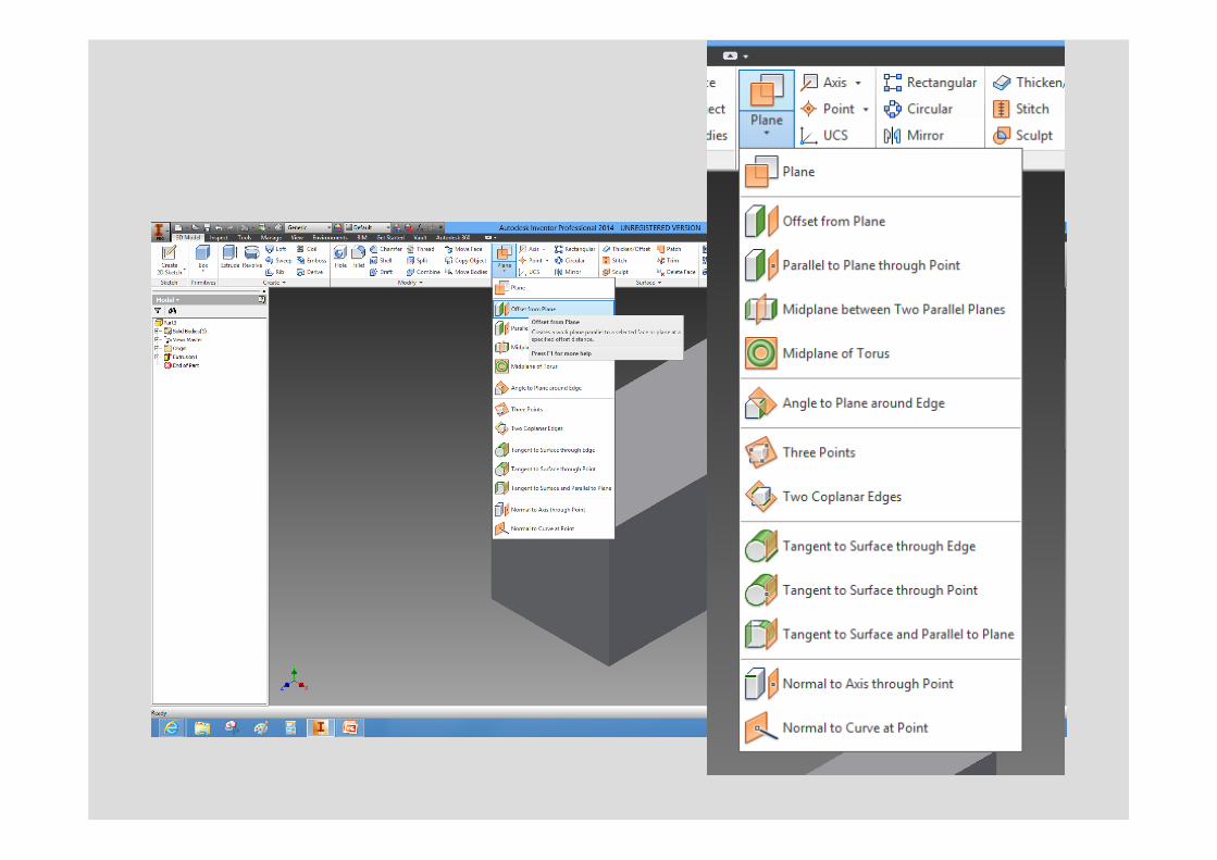
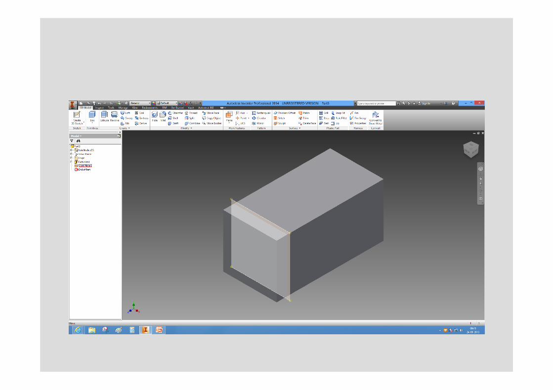
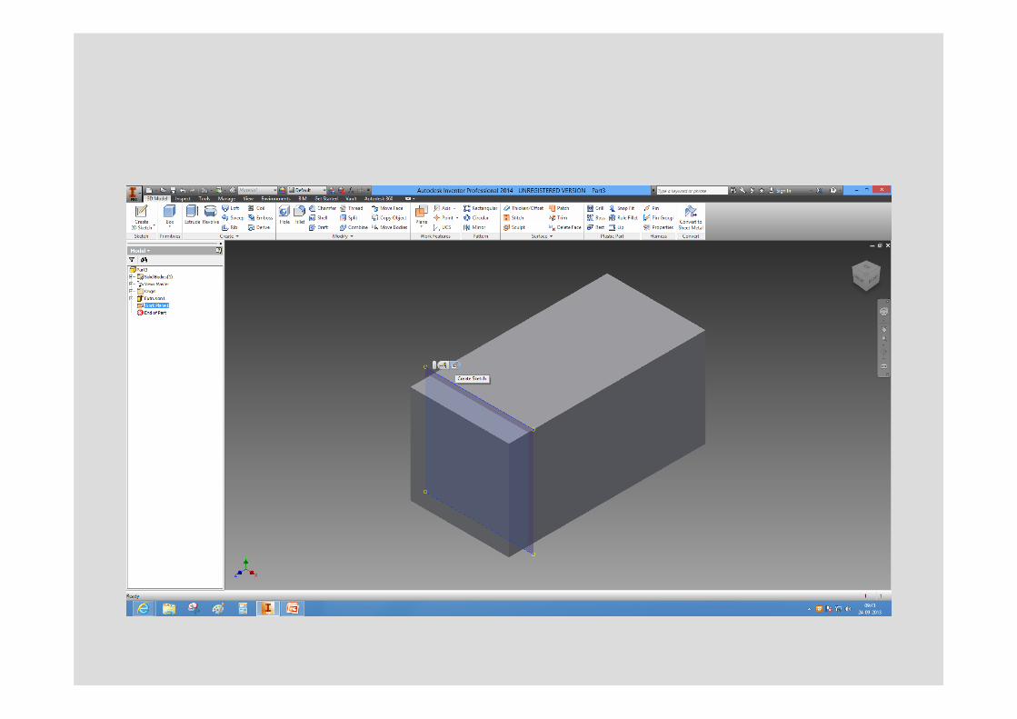
Step 7: Take a plane offset by 40 mm from the sketch plane.
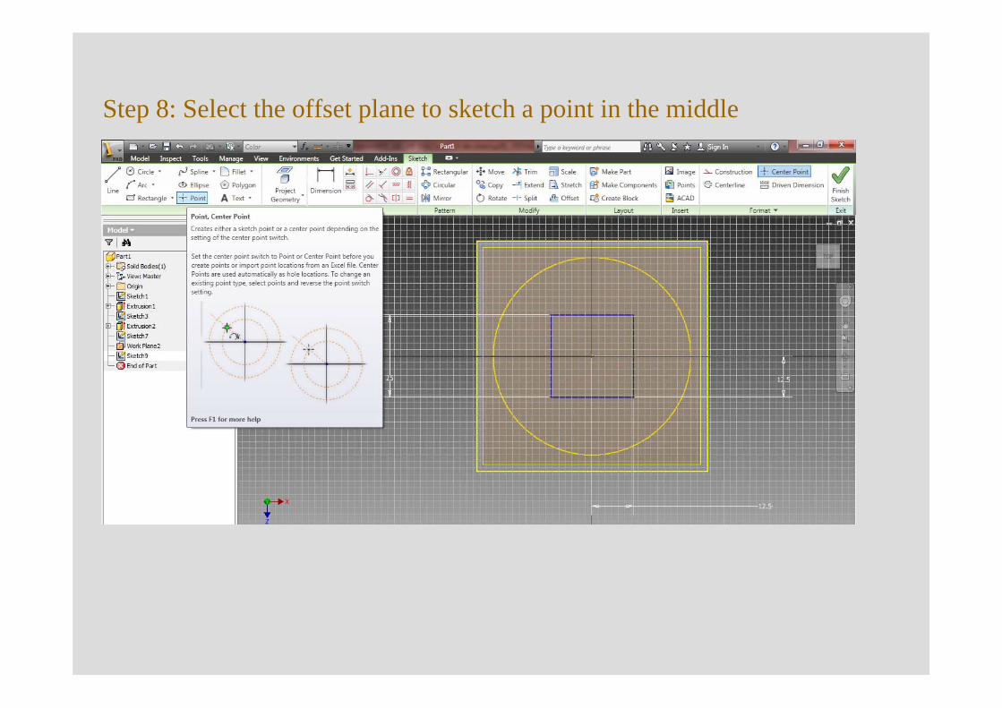
Step 8: Select the offset plane to sketch a point in the middle
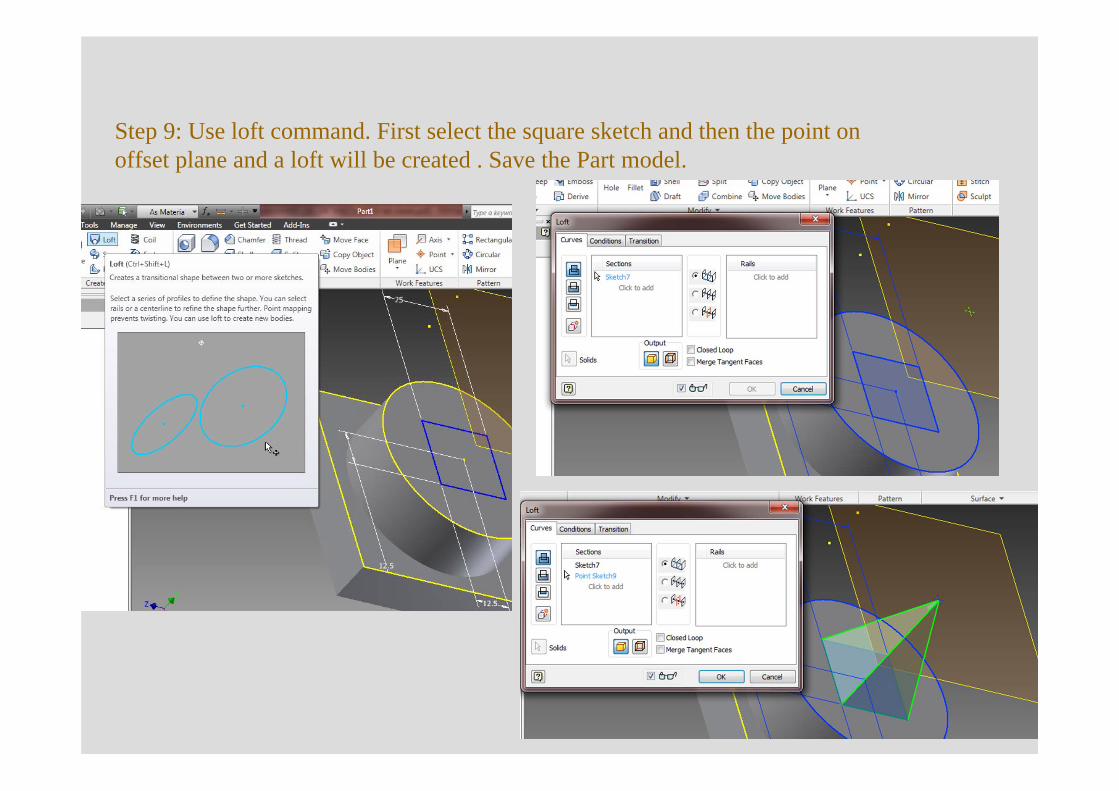
Step 9: Use loft command. First select the square sketch and then the point on offset plane and a loft will be created . Save the Part model.
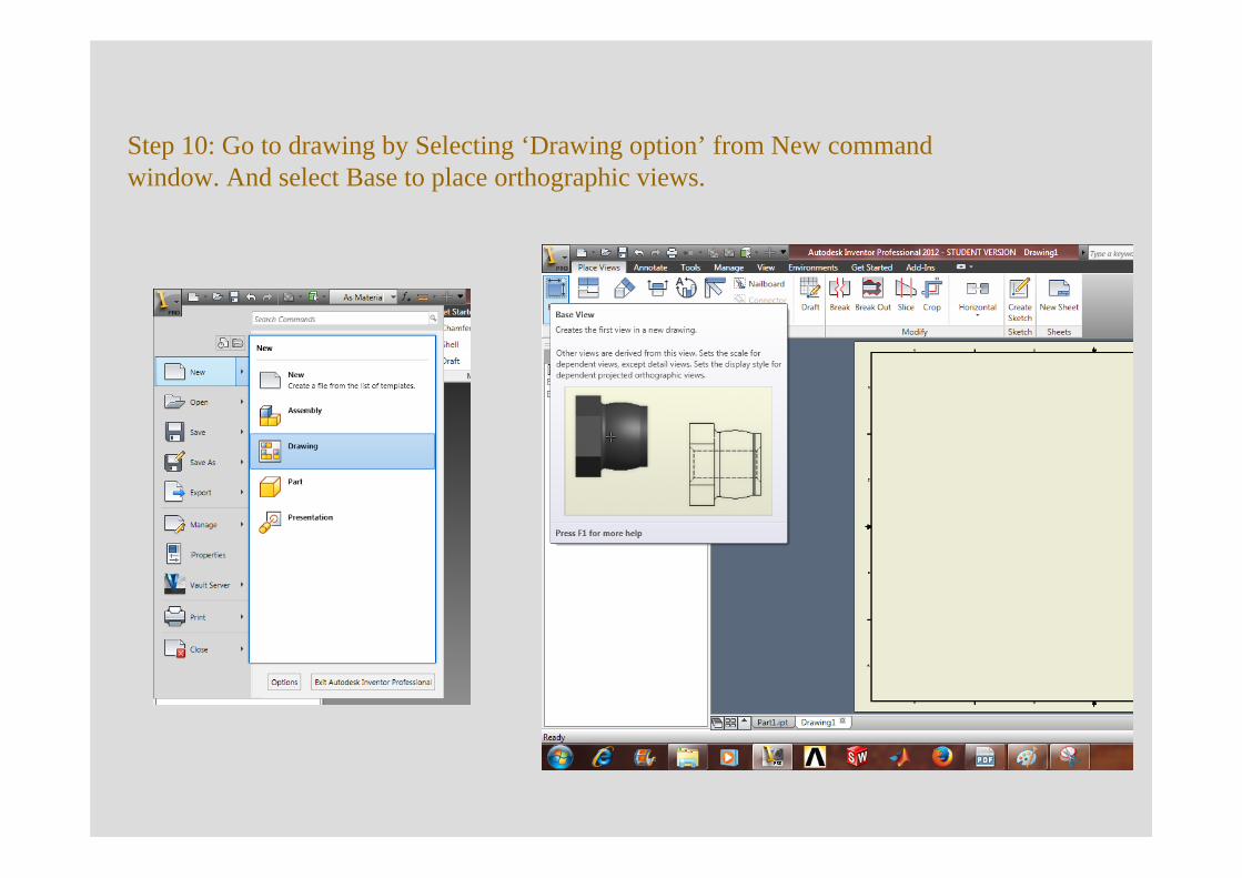
Step 10: Go to drawing by Selecting ‘Drawing option’ from New command window. And select Base to place orthographic views.
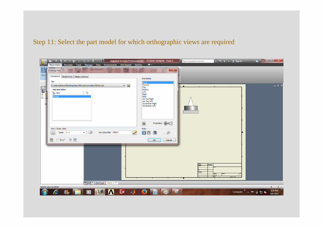
Step 11: Select the part model for which orthographic views are required
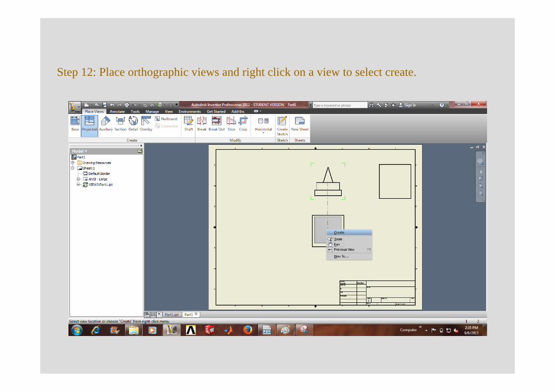
Step 12: Place orthographic views and right click on a view to select create.
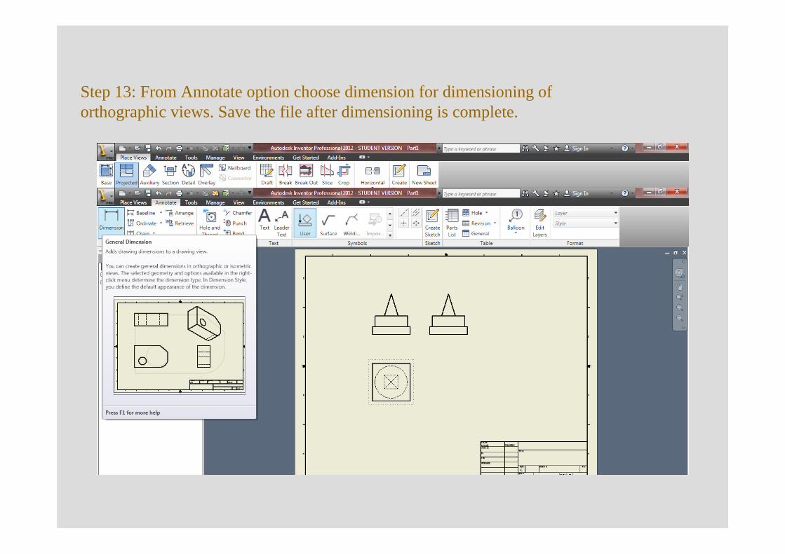
Step 13: From Annotate option choose dimension for dimensioning of orthographic views. Save the file after dimensioning is complete.
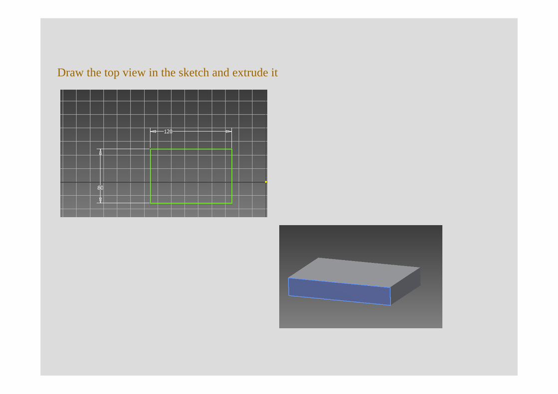
Draw the top view in the sketch and extrude it
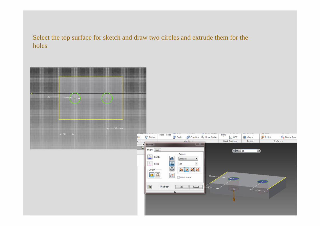
Select the top surface for sketch and draw two circles and extrude them for the holes
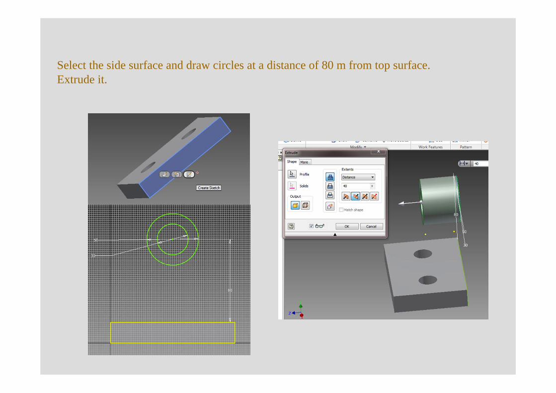
Select the side surface and draw circles at a distance of 80 m from top surface. Extrude it.
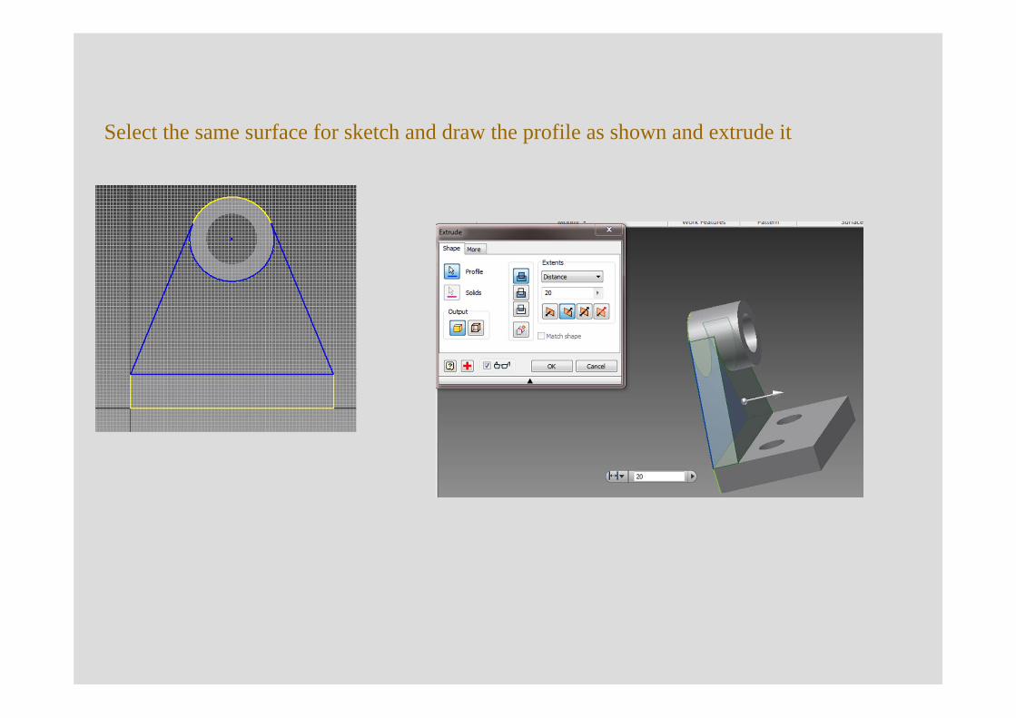
Select the same surface for sketch and draw the profile as shown and extrude it
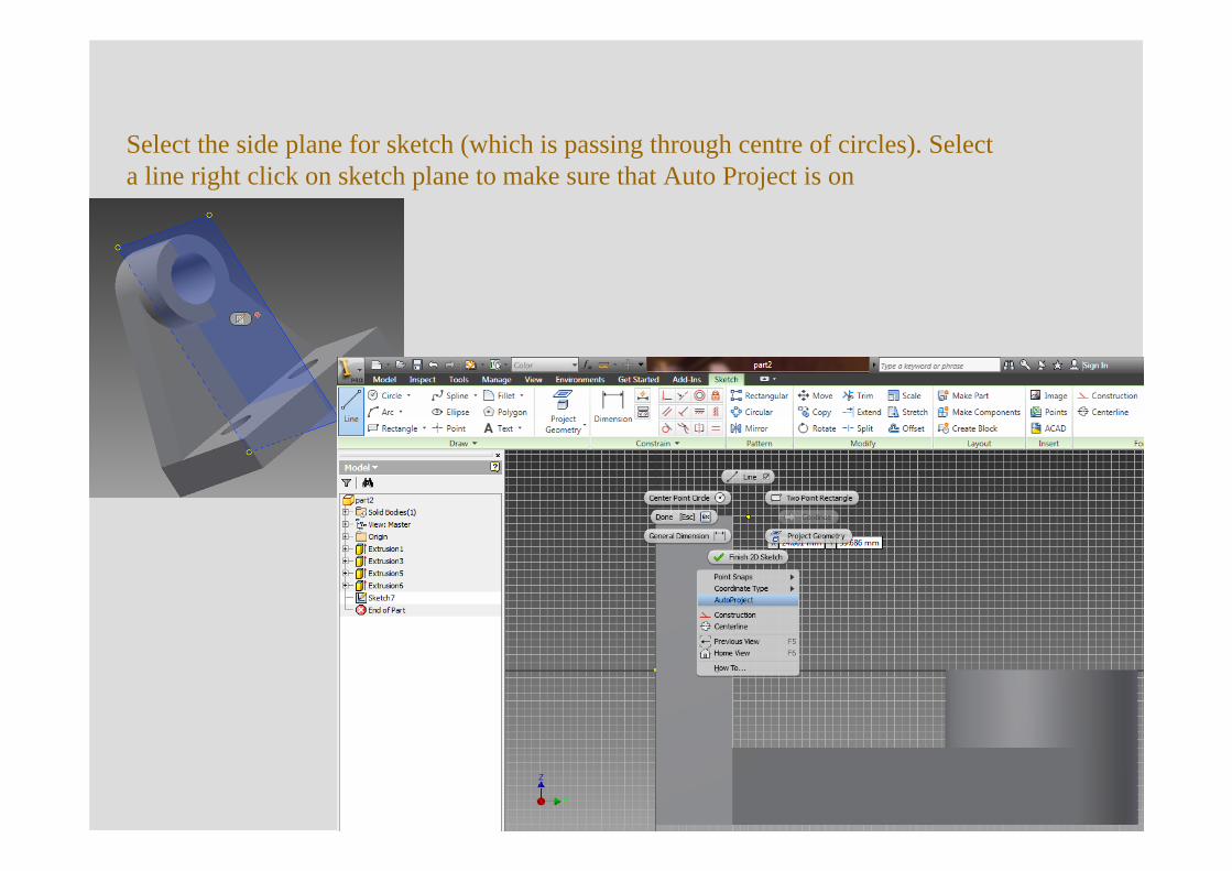
Select the side plane for sketch (which is passing through centre of circles). Select a line right click on sketch plane to make sure that Auto Project is on
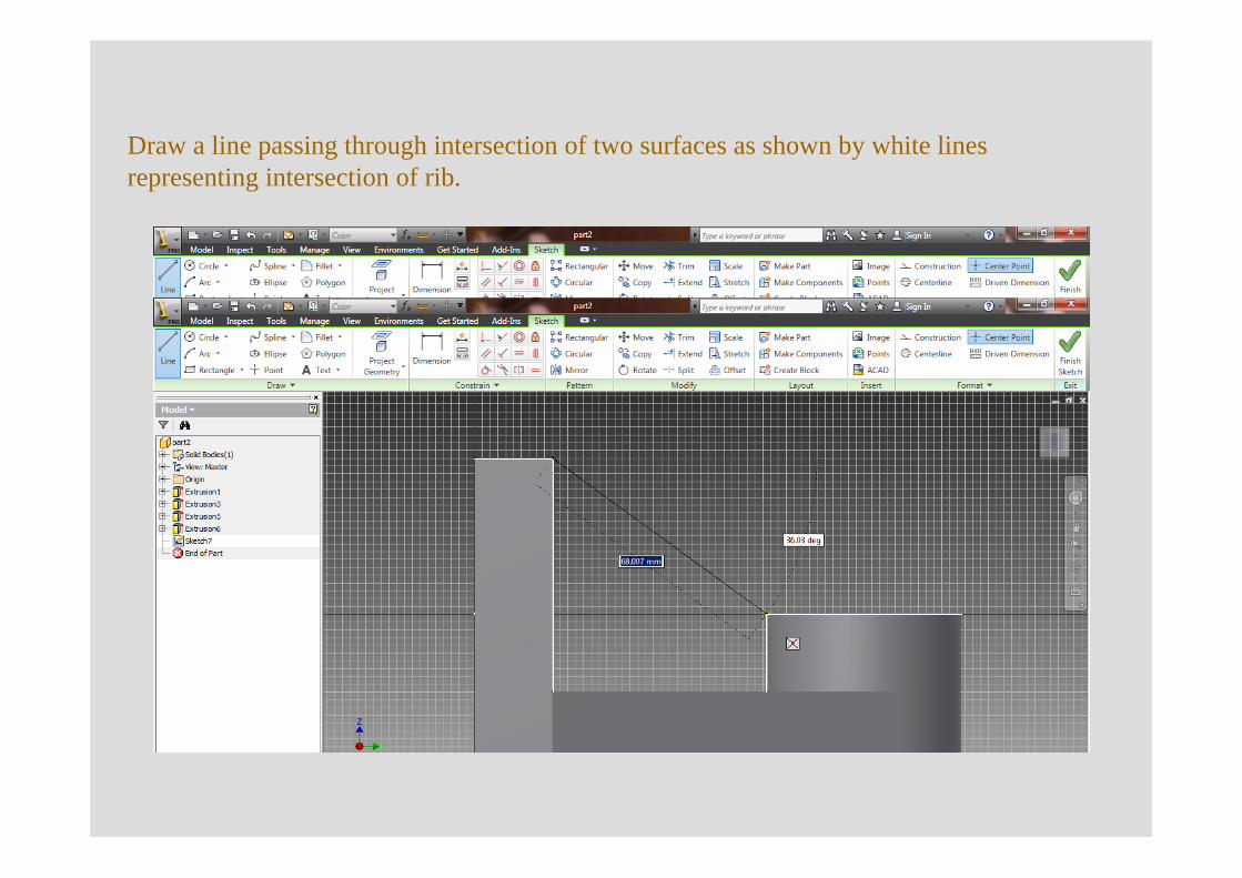
Draw a line passing through intersection of two surfaces as shown by white lines representing intersection of rib.
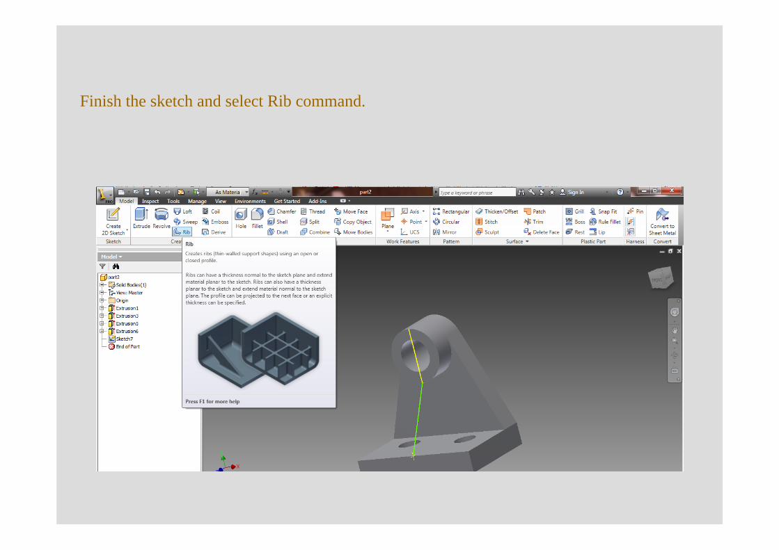
Finish the sketch and select Rib command.
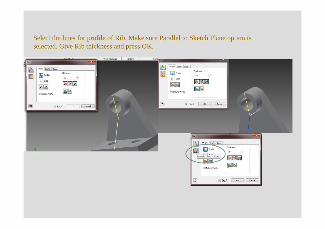
Select the lines for profile of Rib. Make sure Parallel to Sketch Plane option is selected. Give Rib thickness and press OK.
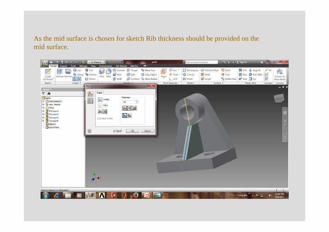
As the mid surface is chosen for sketch Rib thickness should be provided on the mid surface.
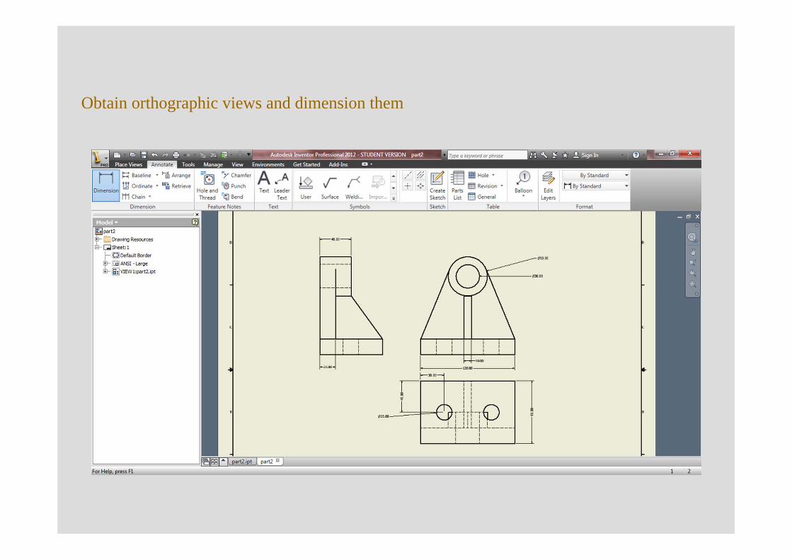
Obtain orthographic views and dimension them
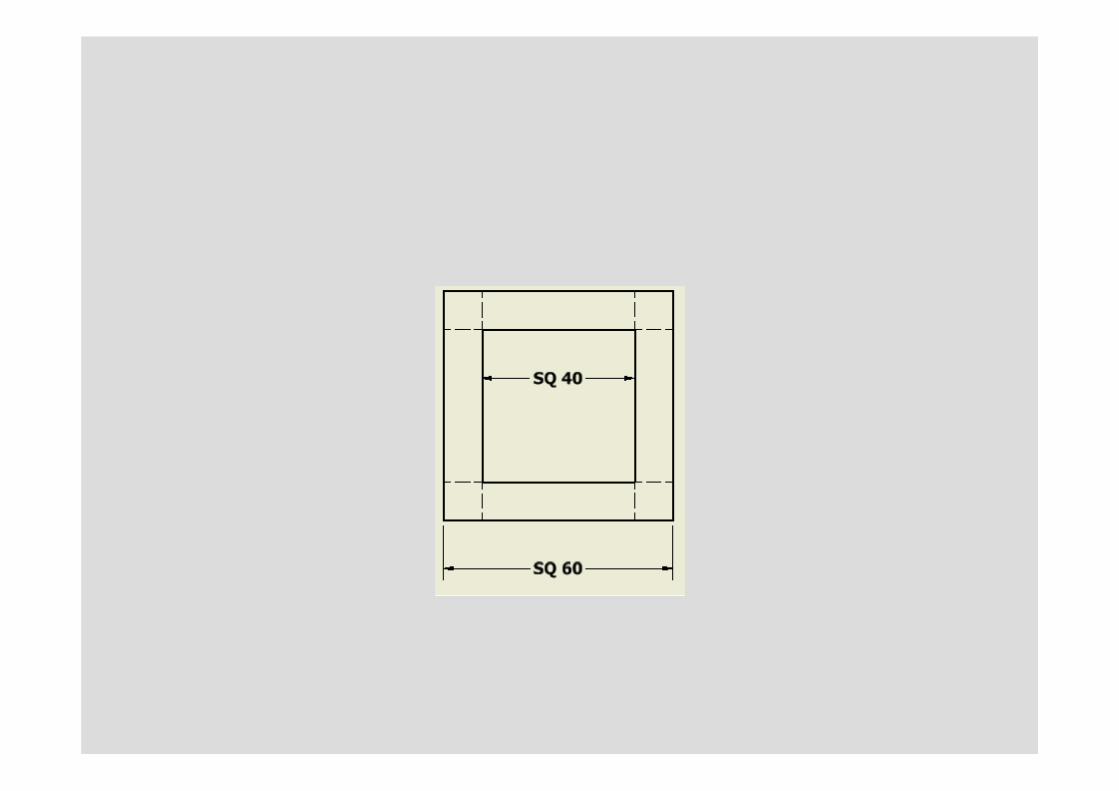
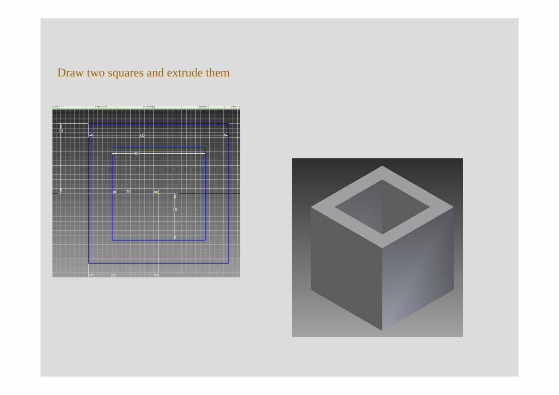
Draw two squares and extrude them
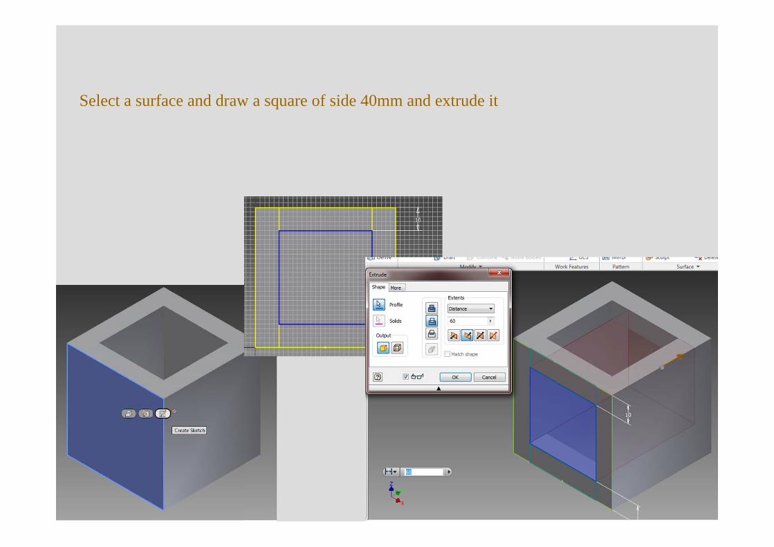
Select a surface and draw a square of side 40mm and extrude it
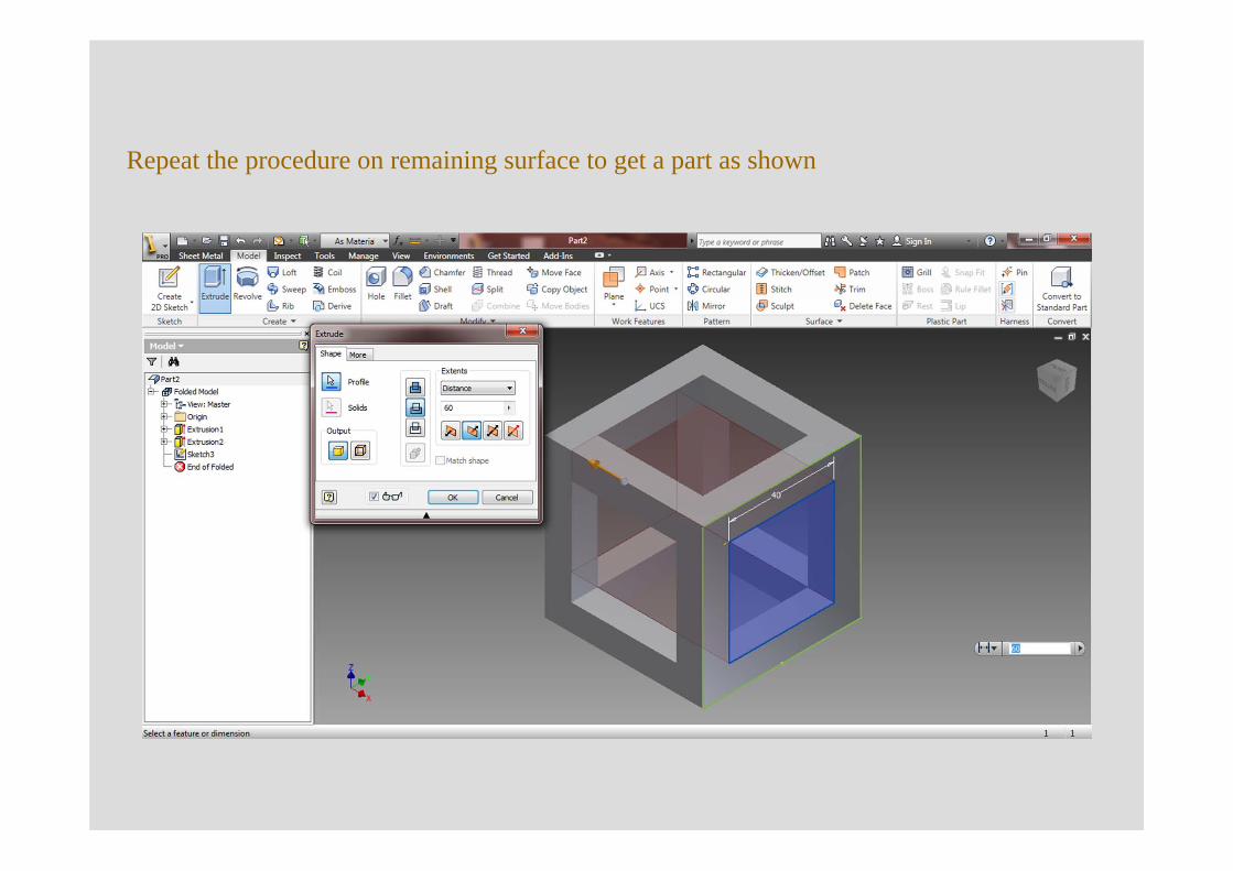
Repeat the procedure on remaining surface to get a part as shown
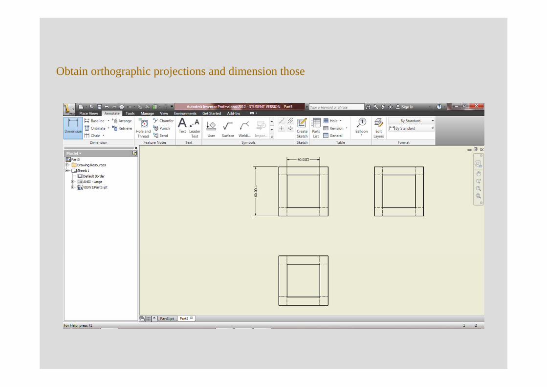
Obtain orthographic projections and dimension those
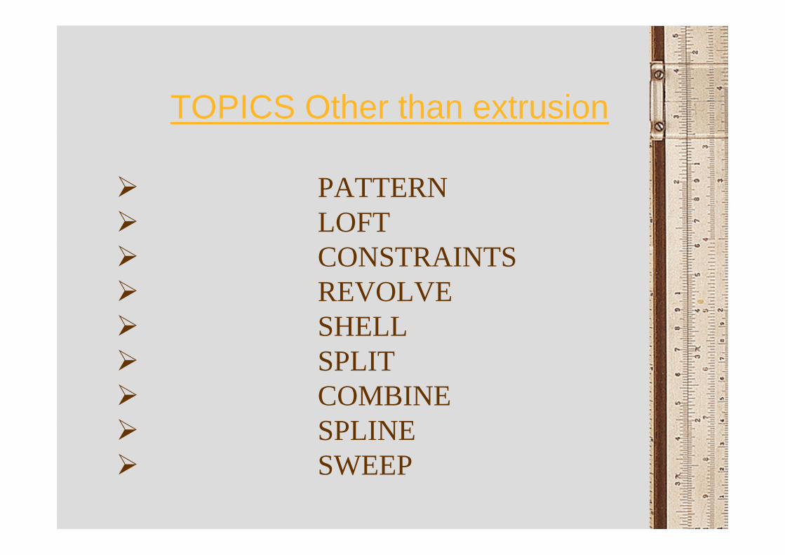
TOPICS Other than extrusion
PATTERNLOFTCONSTRAINTSREVOLVESHELLSPLITCOMBINESPLINESWEEP
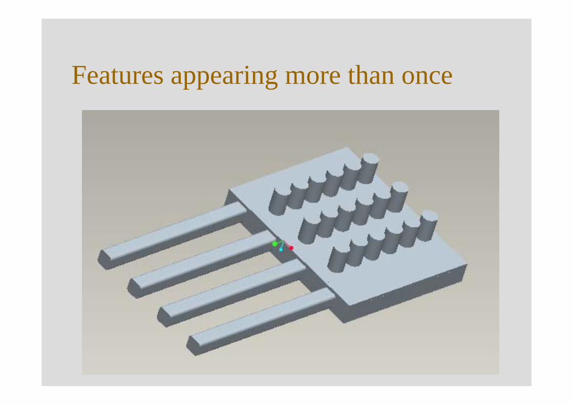
Features appearing more than once
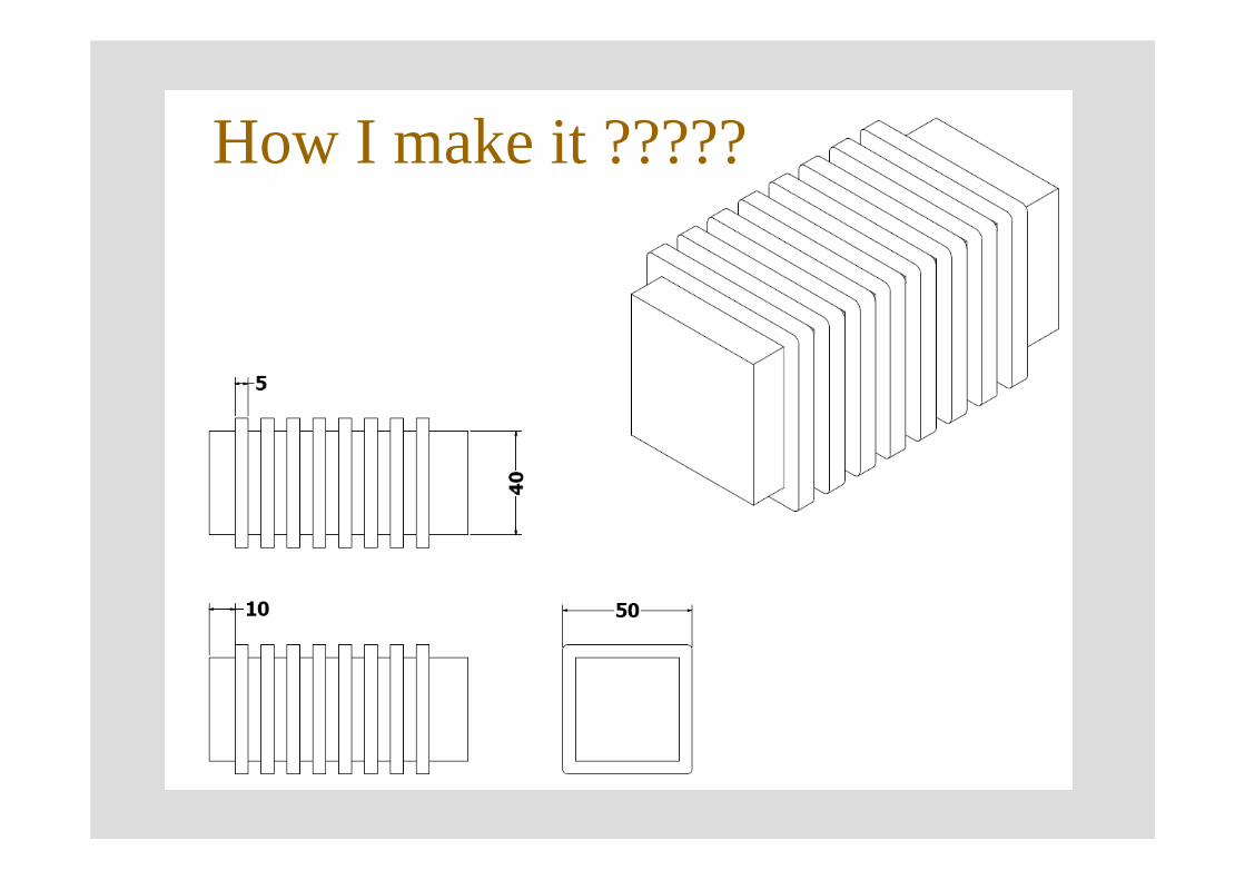
How I make it ?????
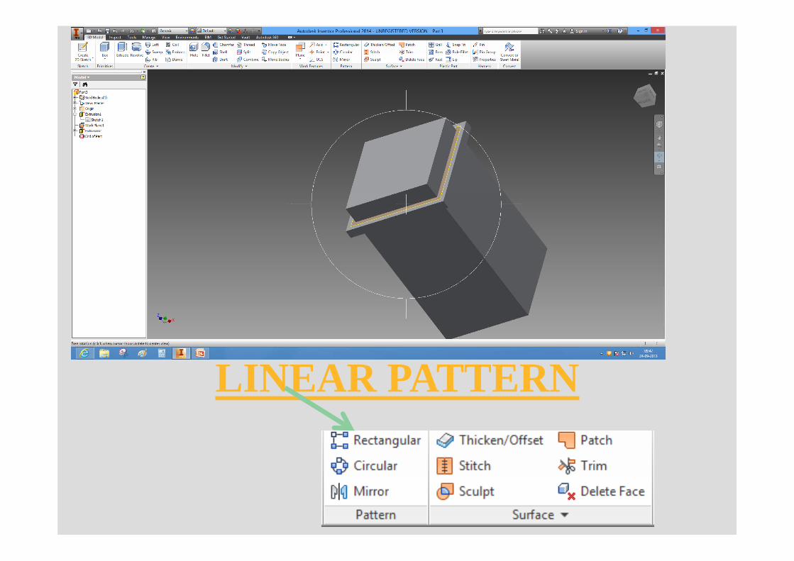
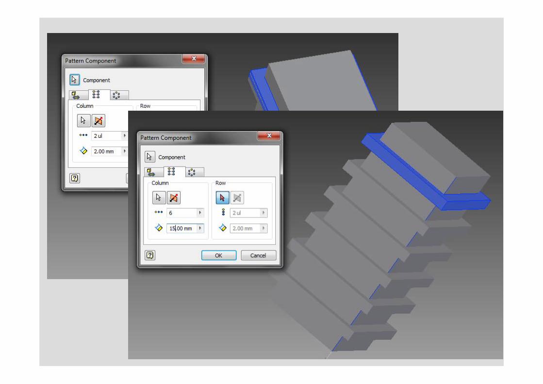
LINEAR PATTERN
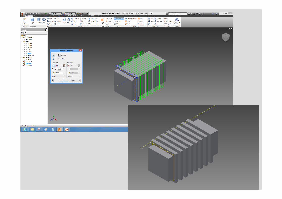
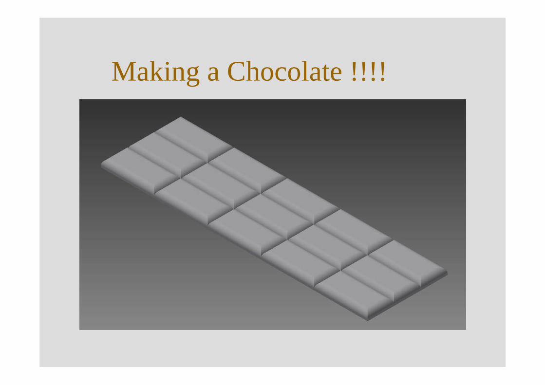
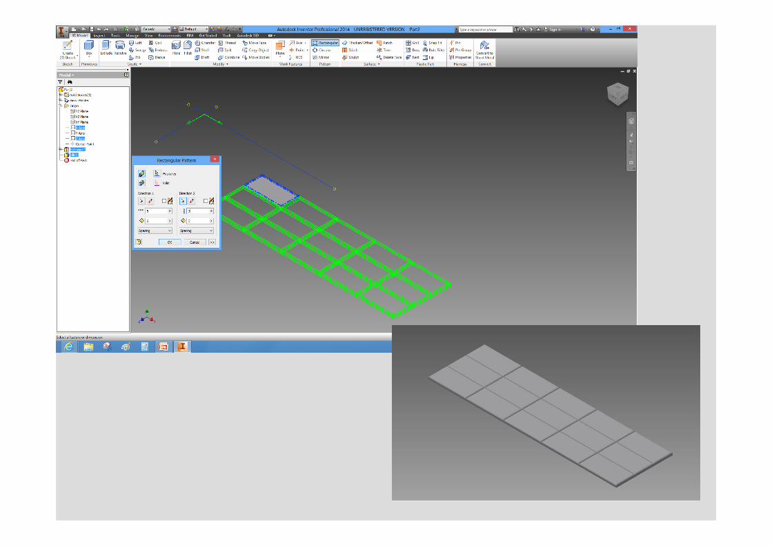
Making a Chocolate !!!!
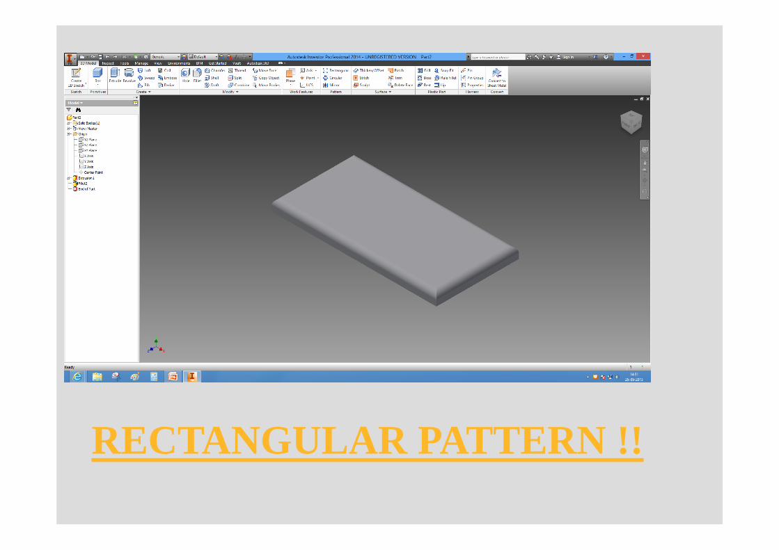
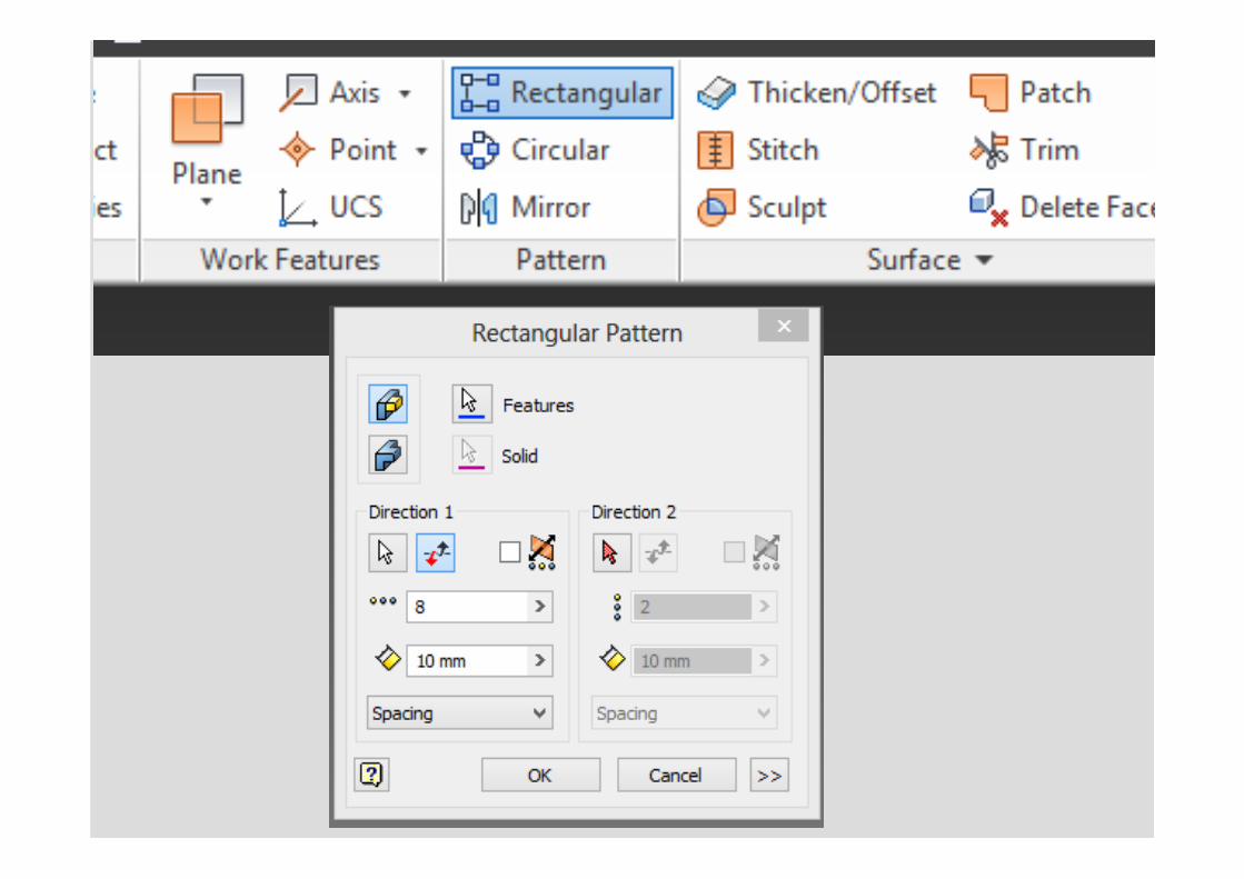
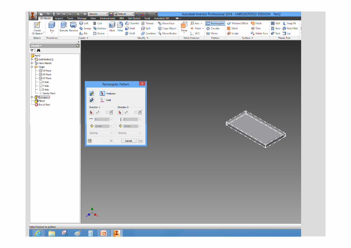
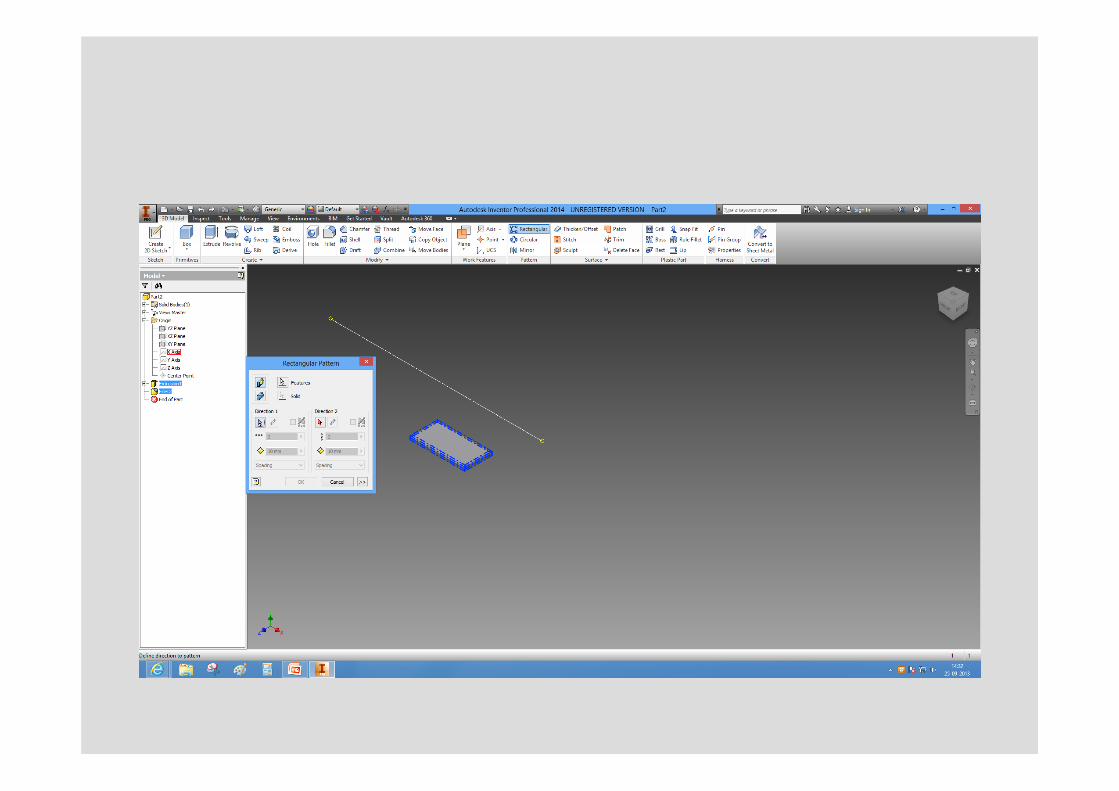
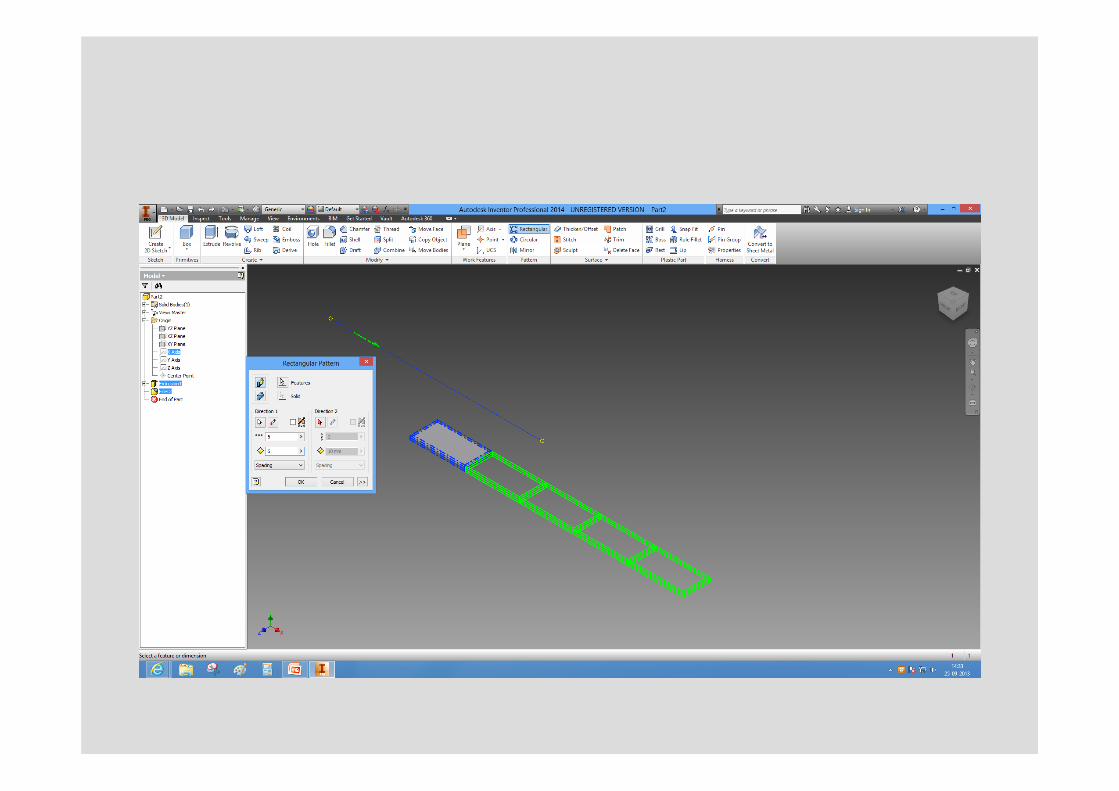
RECTANGULAR PATTERN !!
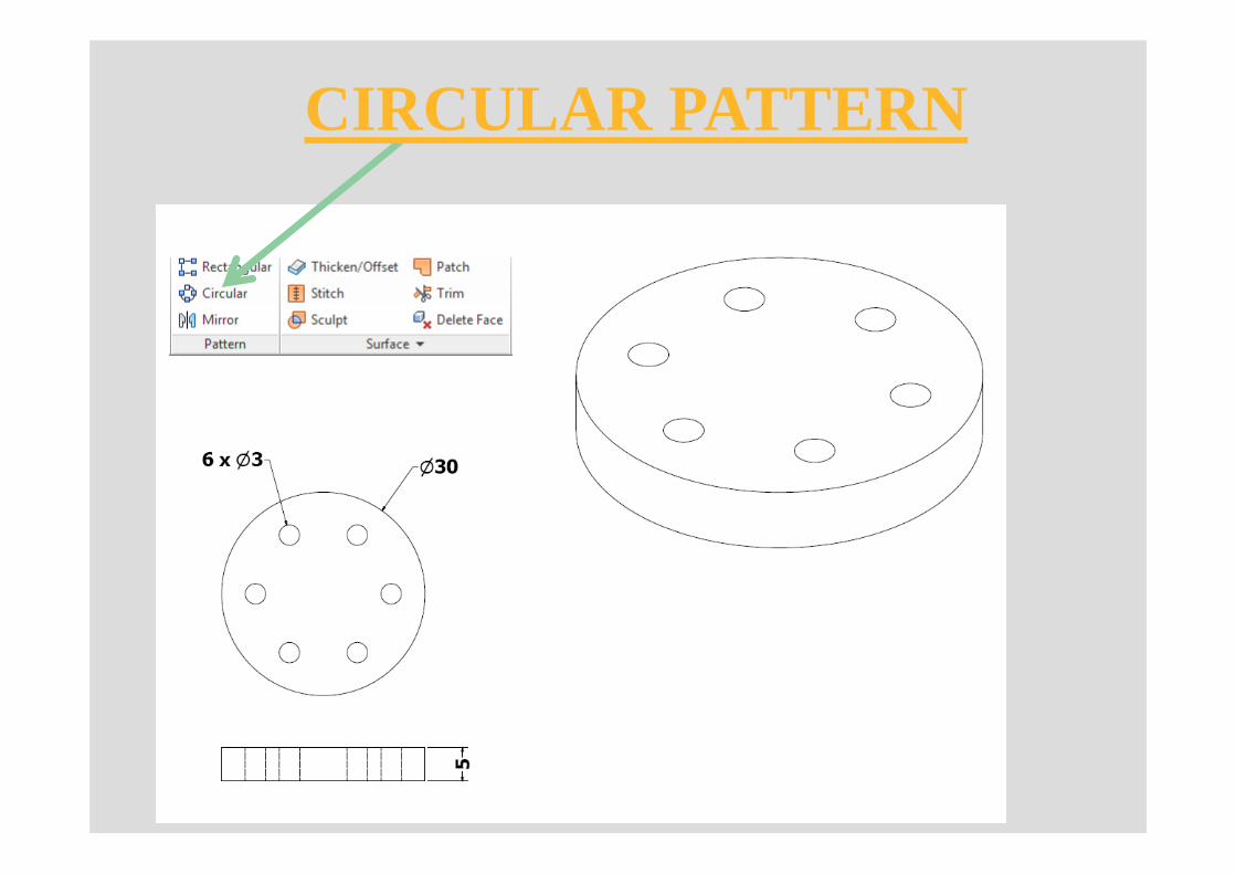
CIRCULAR PATTERN
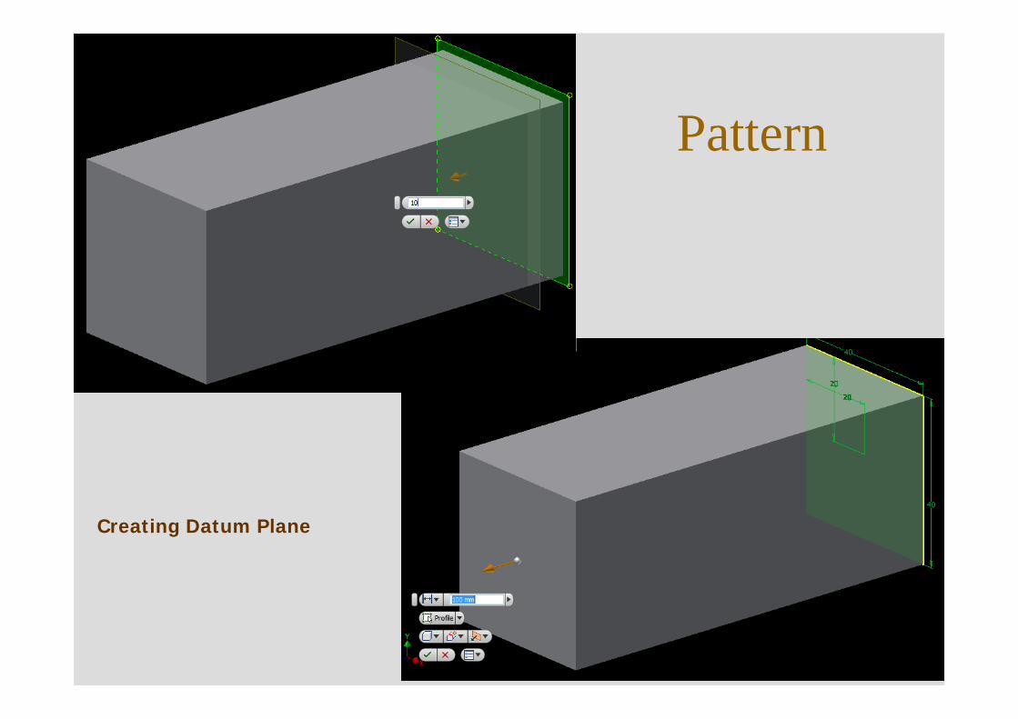
Pattern
Creating Datum Plane
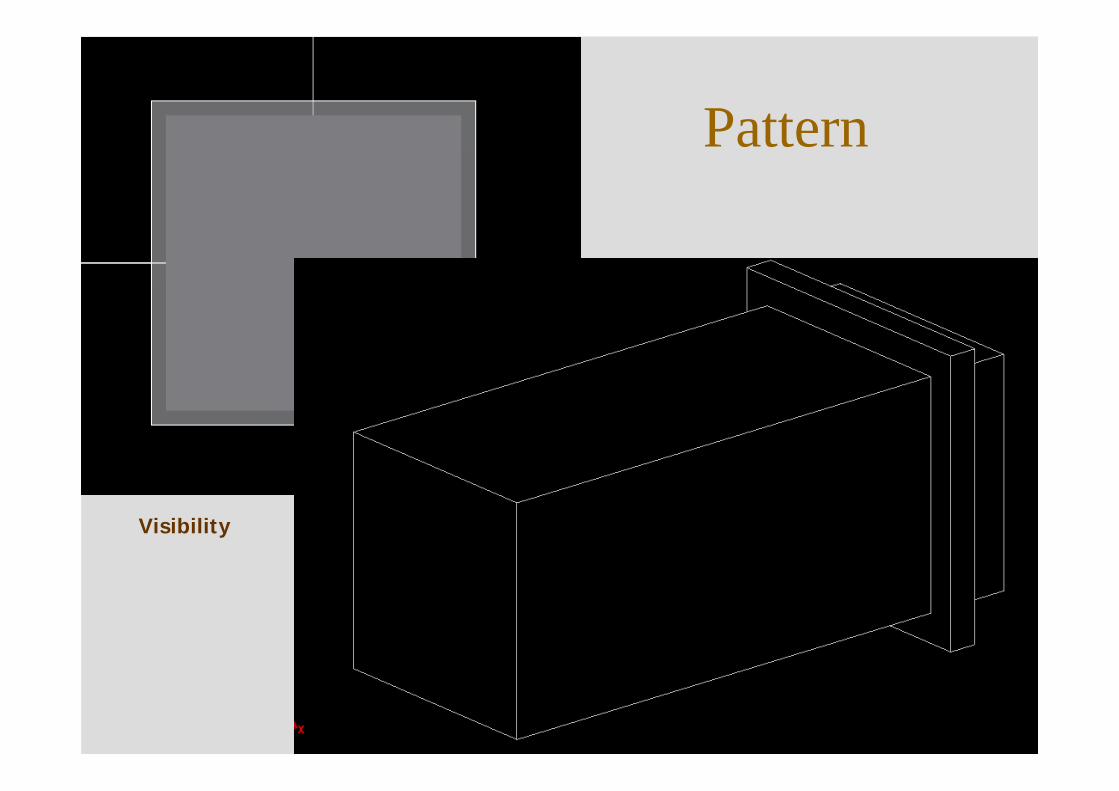
Pattern
Visibility
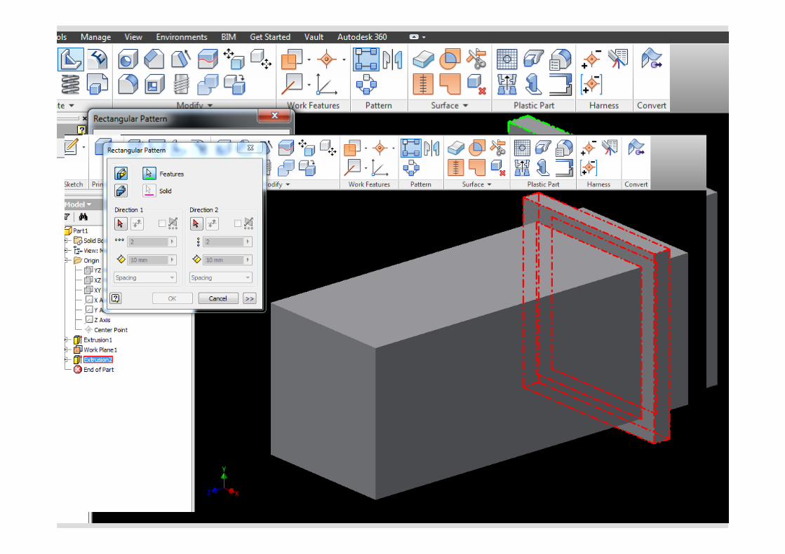
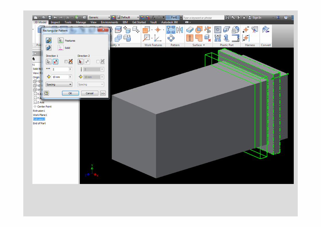
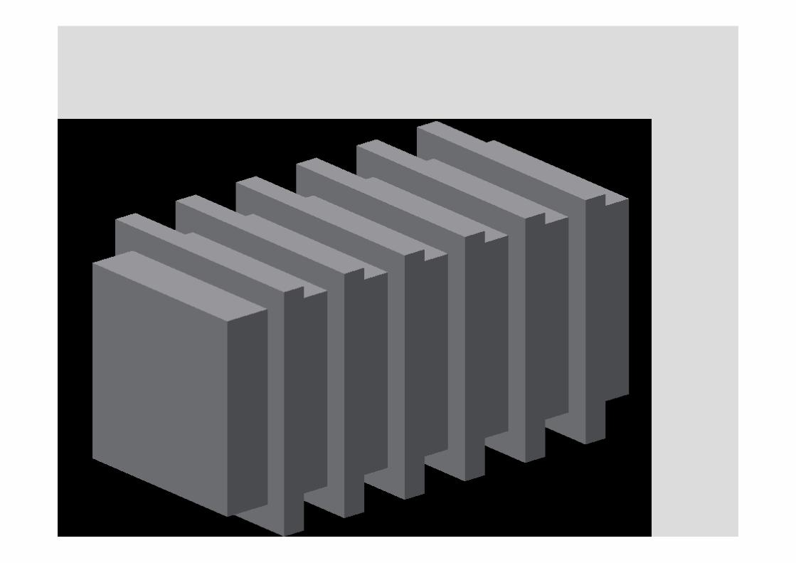
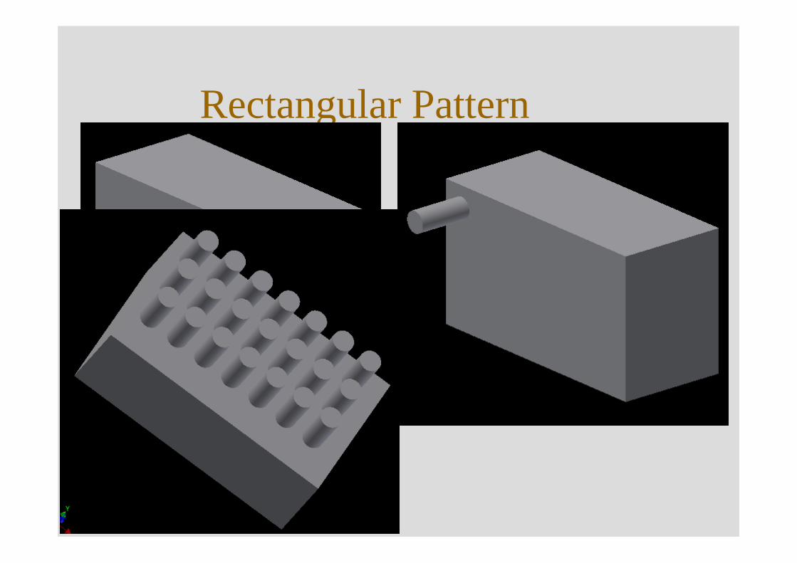
Rectangular Pattern
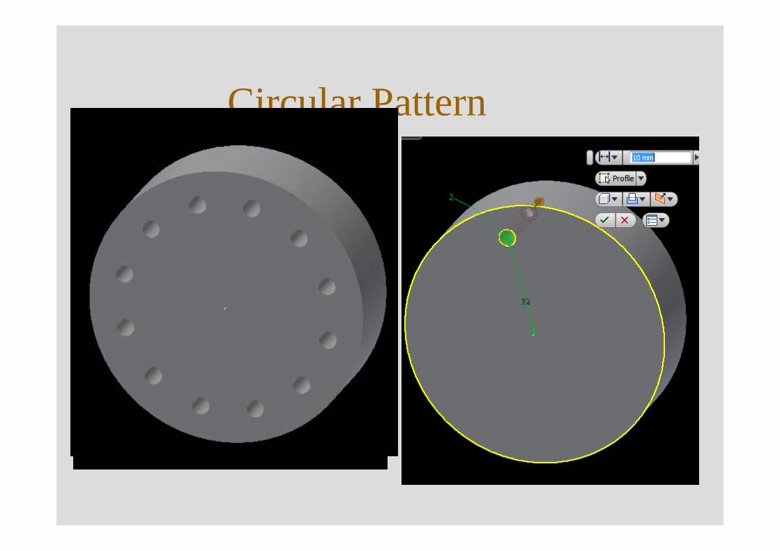
Circular Pattern
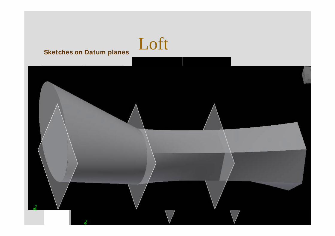
LoftSketches on Datum planes
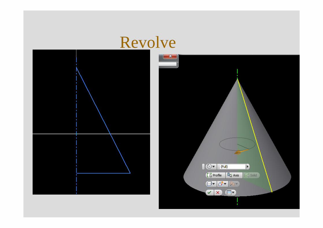
Revolve
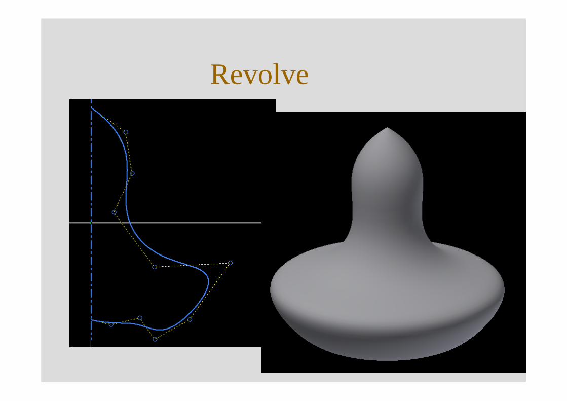
Revolve
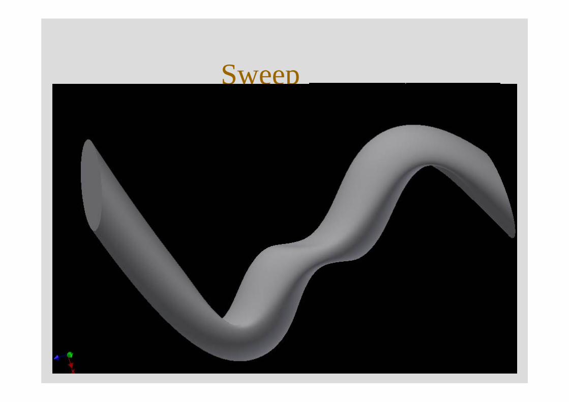
SweepSection + Path
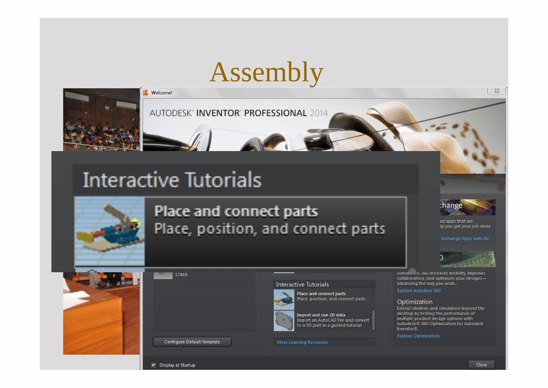
Assembly
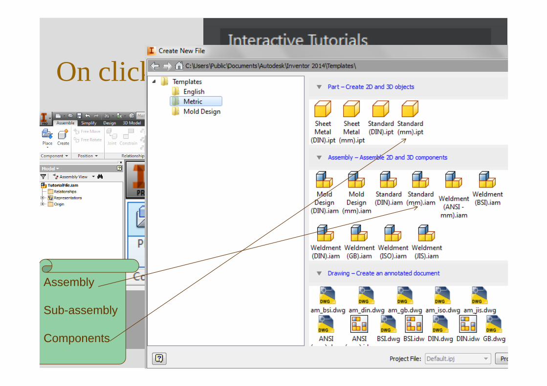
On clicking
Assembly
Sub-assembly
Components
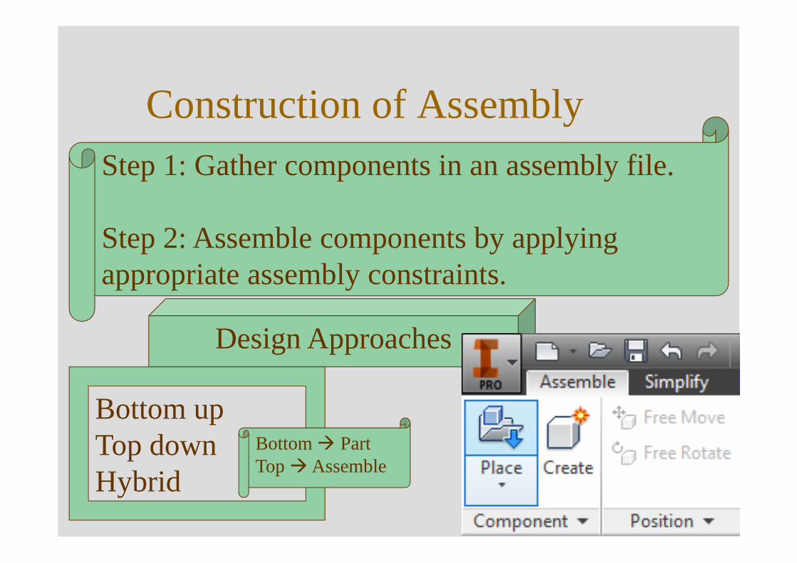
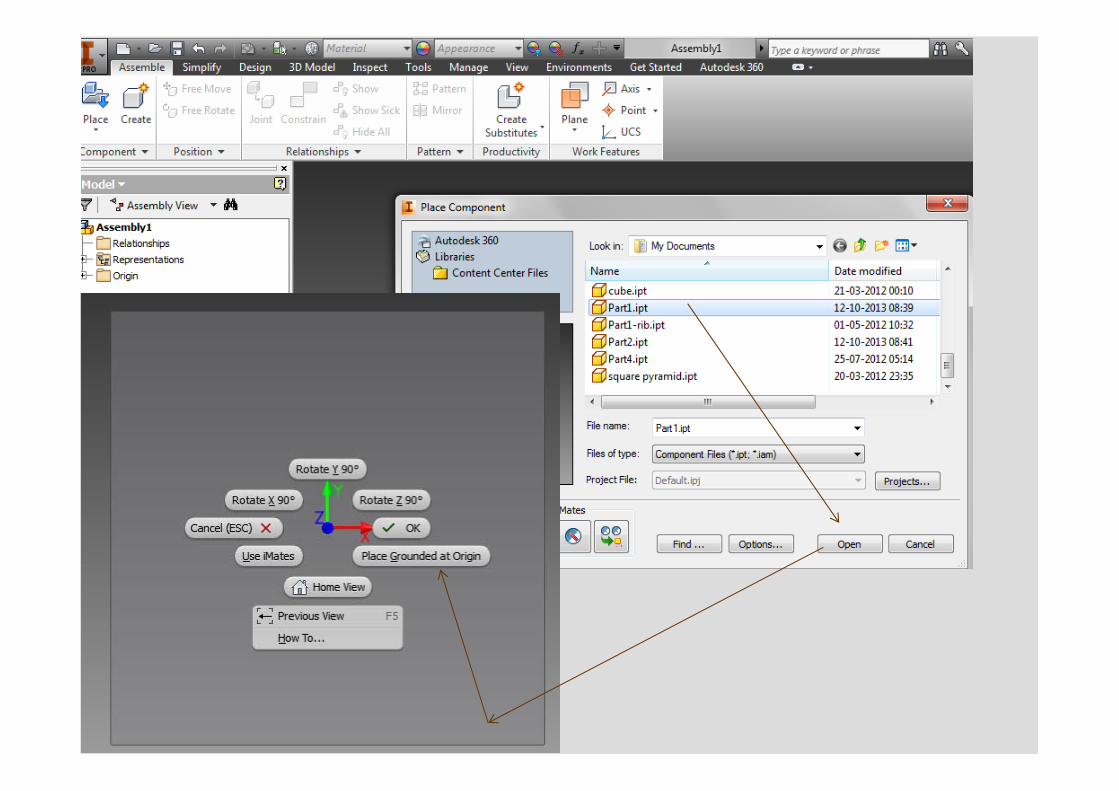
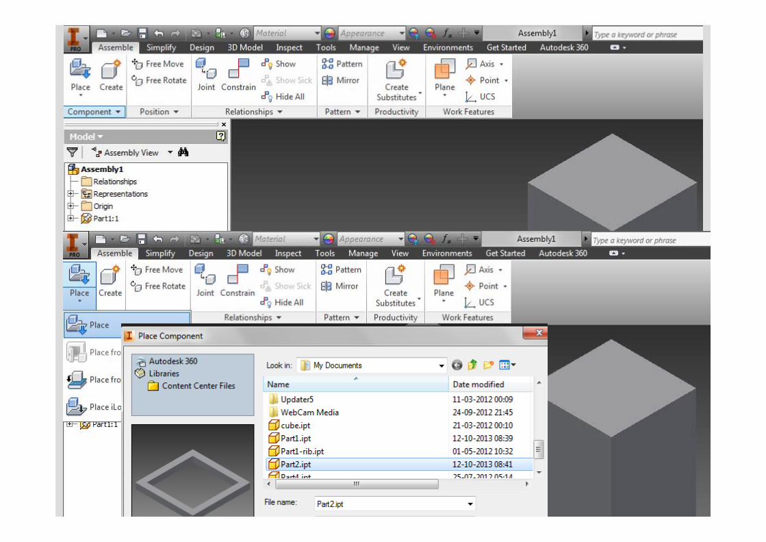
Construction of AssemblyStep 1: Gather components in an assembly file.
Step 2: Assemble components by applying appropriate assembly constraints.
Design Approaches
Bottom upTop downHybrid
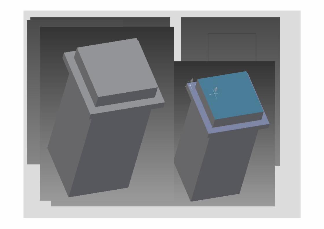
Bottom PartTop Assemble
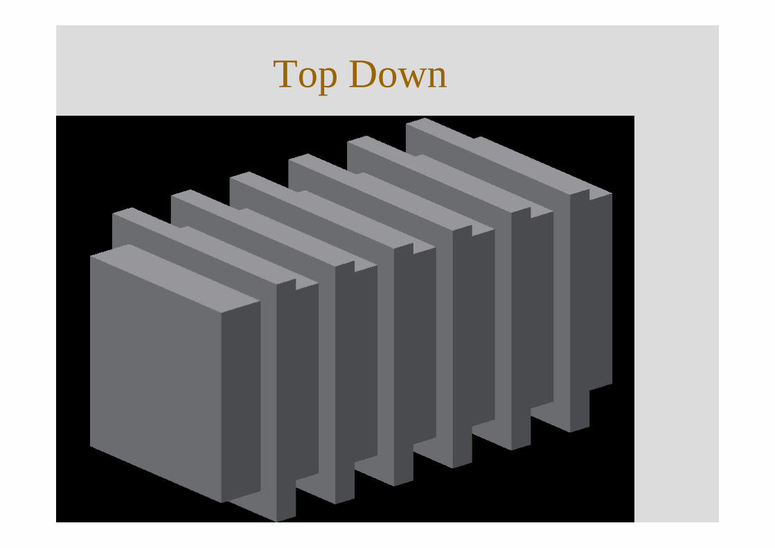
Top Down
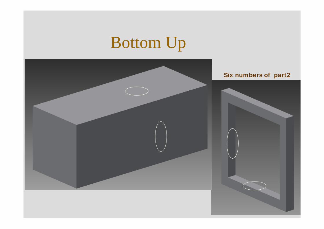
Bottom Up
Six numbers of part2
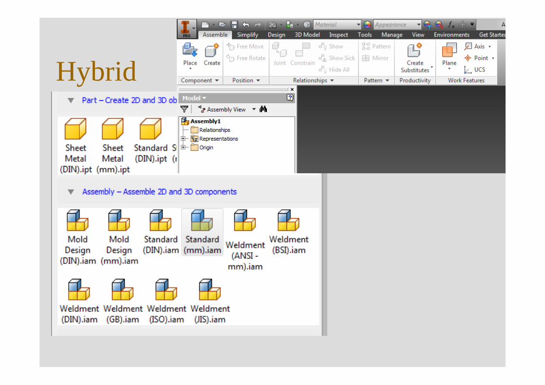
Hybrid
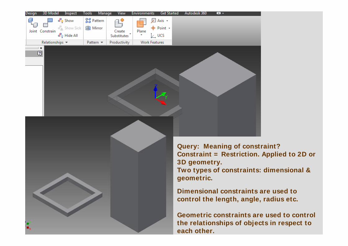
Query: Meaning of constraint? Constraint = Restriction. Applied to 2D or 3D geometry. Two types of constraints: dimensional & geometric.
Dimensional constraints are used to control the length, angle, radius etc.
Geometric constraints are used to control the relationships of objects in respect to each other.
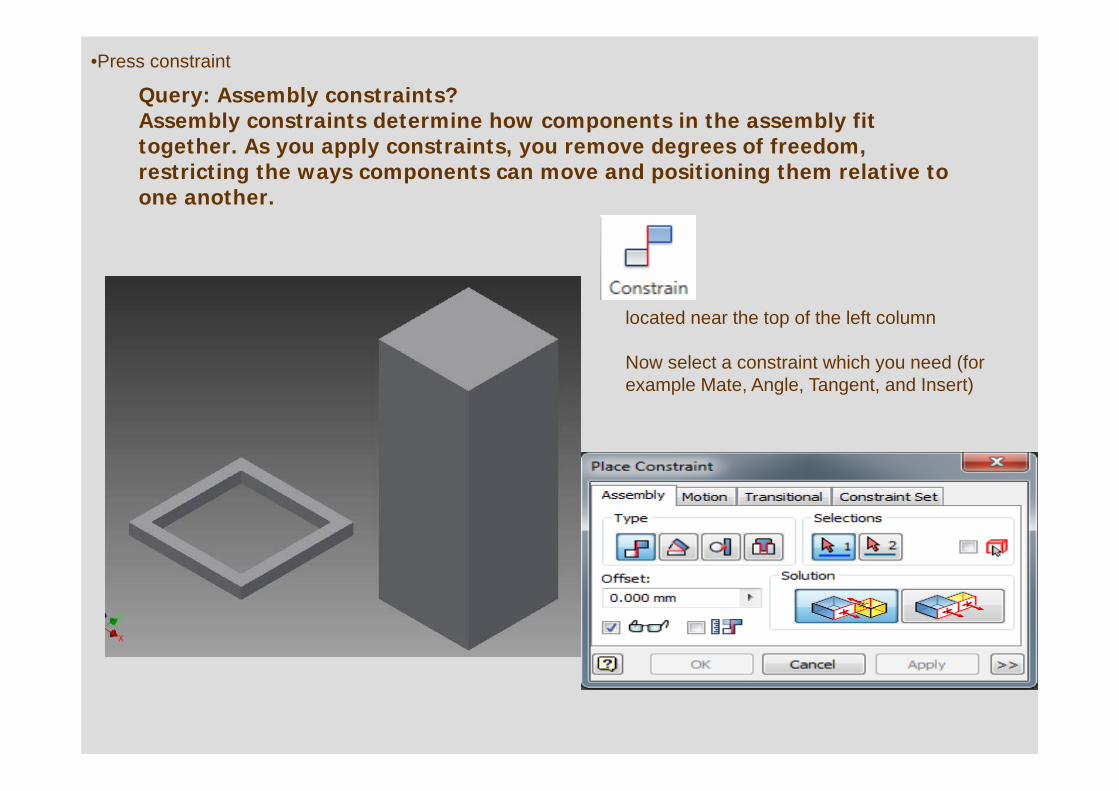
Query: Assembly constraints?Assembly constraints determine how components in the assembly fit together. As you apply constraints, you remove degrees of freedom, restricting the ways components can move and positioning them relative to one another.
•Press constraint
located near the top of the left column
Now select a constraint which you need (for example Mate, Angle, Tangent, and Insert)
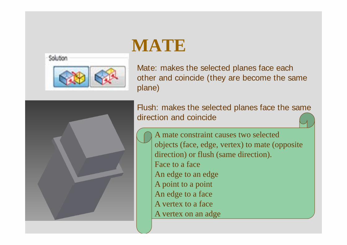
MATEMate: makes the selected planes face each other and coincide (they are become the same plane)
Flush: makes the selected planes face the same direction and coincide
A mate constraint causes two selectedobjects (face, edge, vertex) to mate (opposite direction) or flush (same direction). Face to a faceAn edge to an edgeA point to a pointAn edge to a faceA vertex to a faceA vertex on an adge
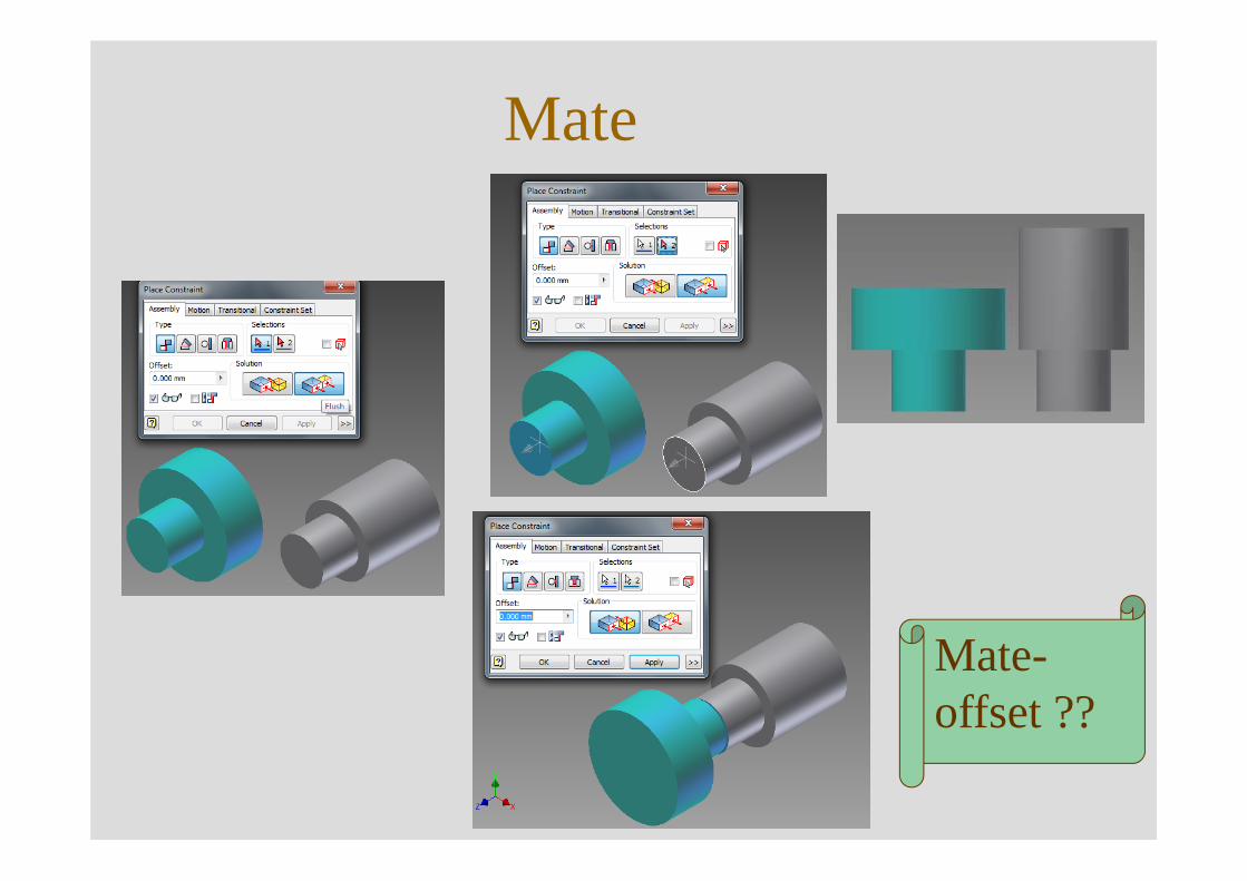
Mate
Mate-offset ??
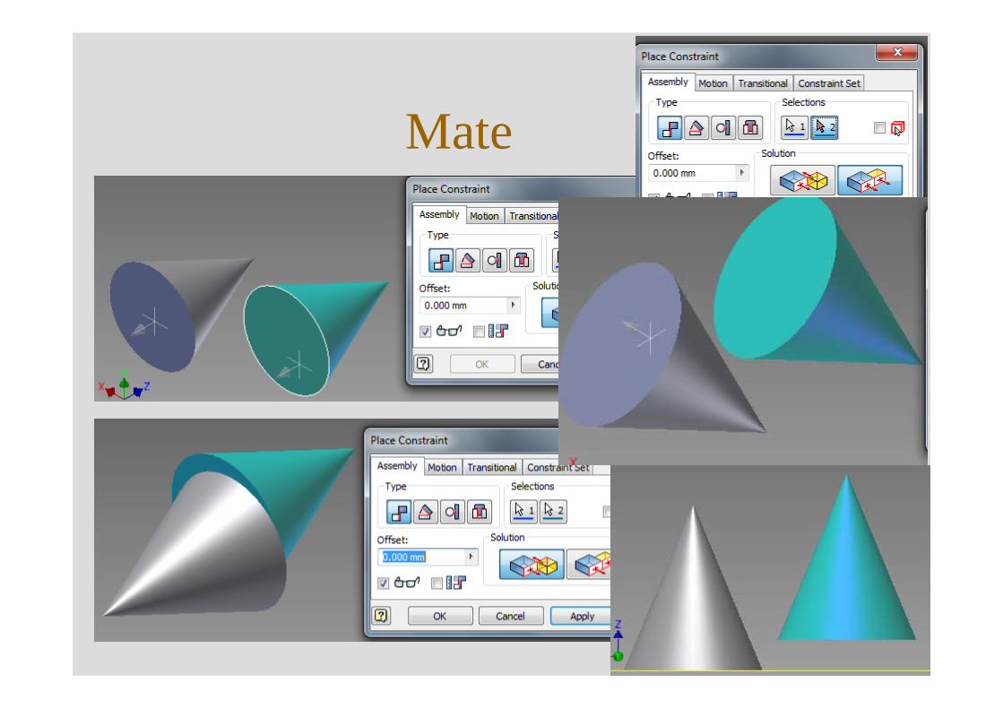
Mate
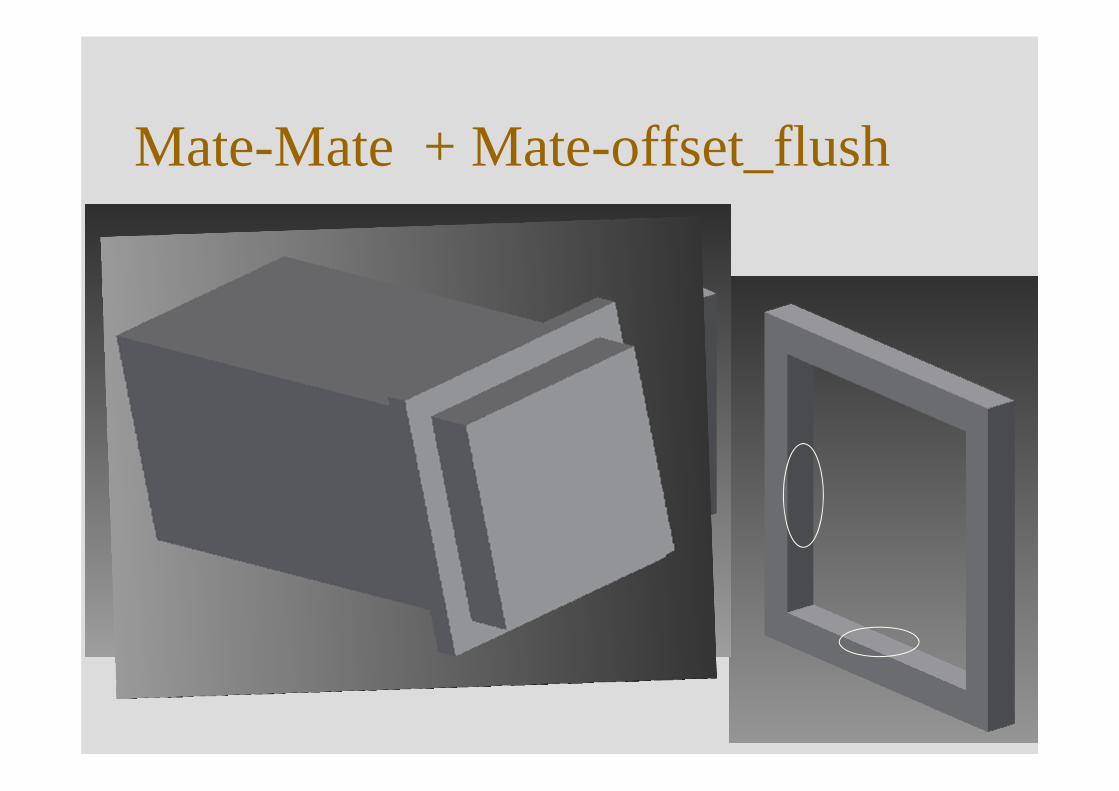
Mate-Mate + Mate-offset_flush
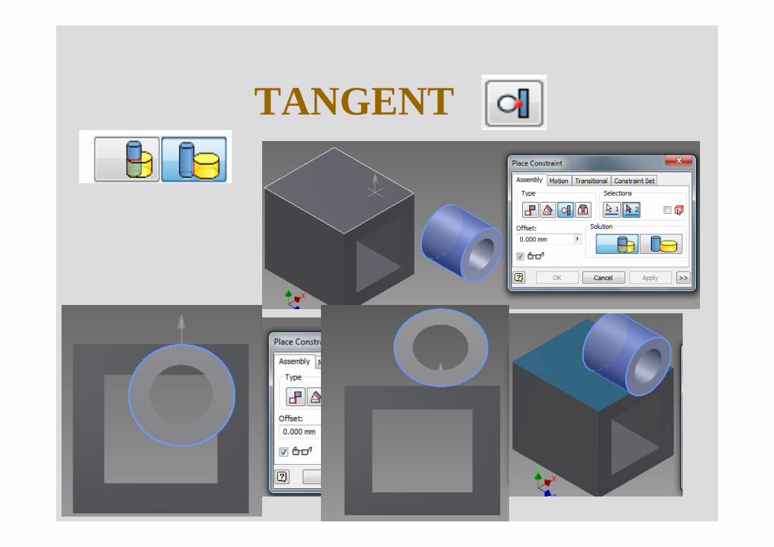
TANGENT
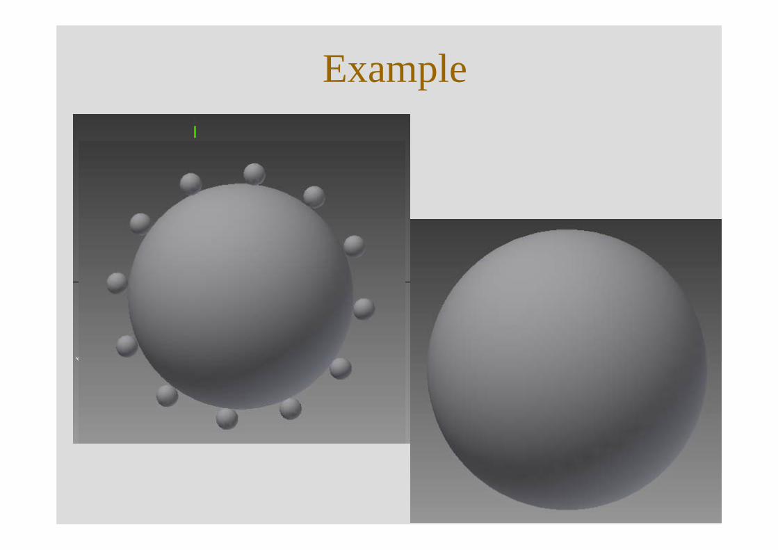
Example
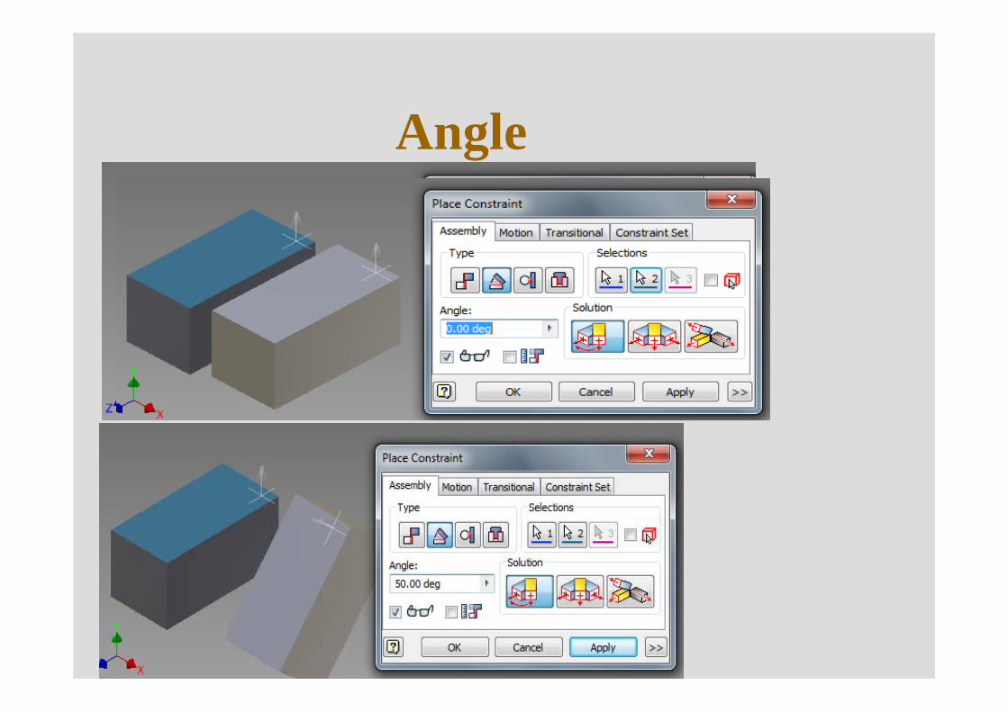
Angle
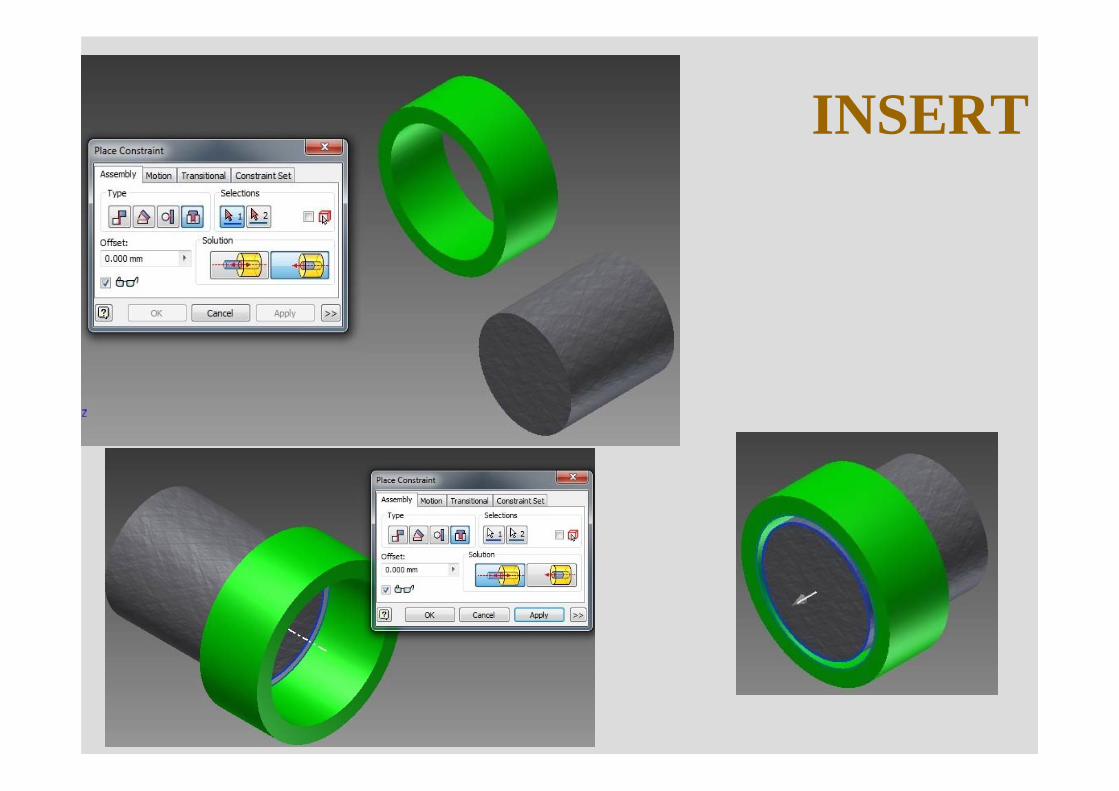
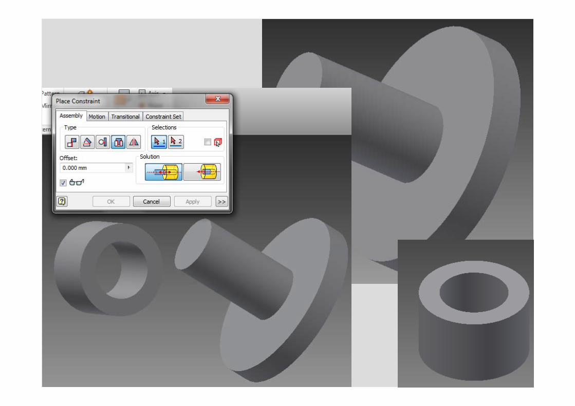
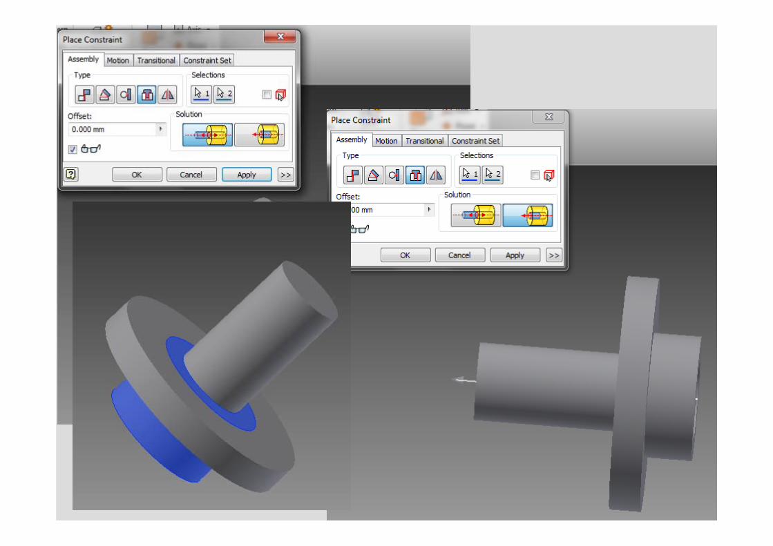
INSERT
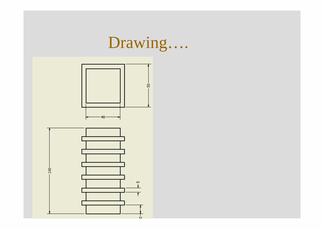
Drawing….
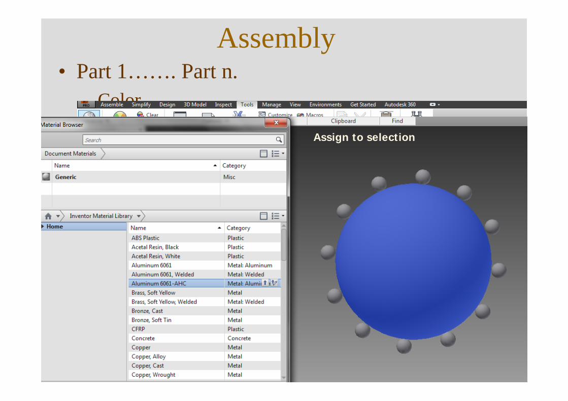
Assembly • Part 1……. Part n.
– Color
Assign to selection
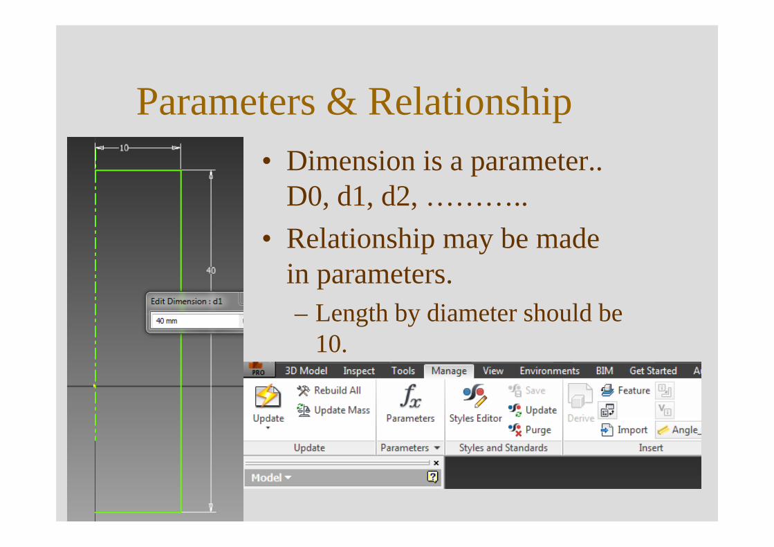
Parameters & Relationship• Dimension is a parameter..
D0, d1, d2, ………..• Relationship may be made
in parameters.– Length by diameter should be
10.
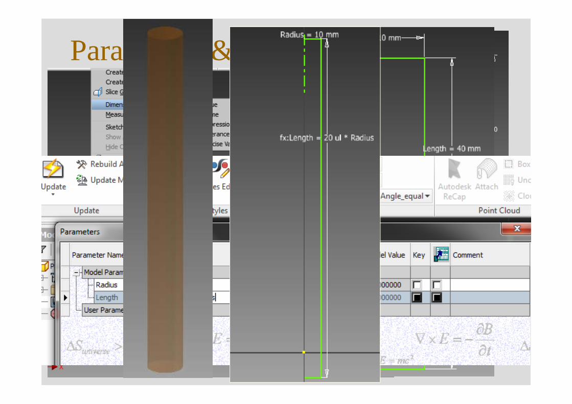
Parameters & Relationship….
No change !!!
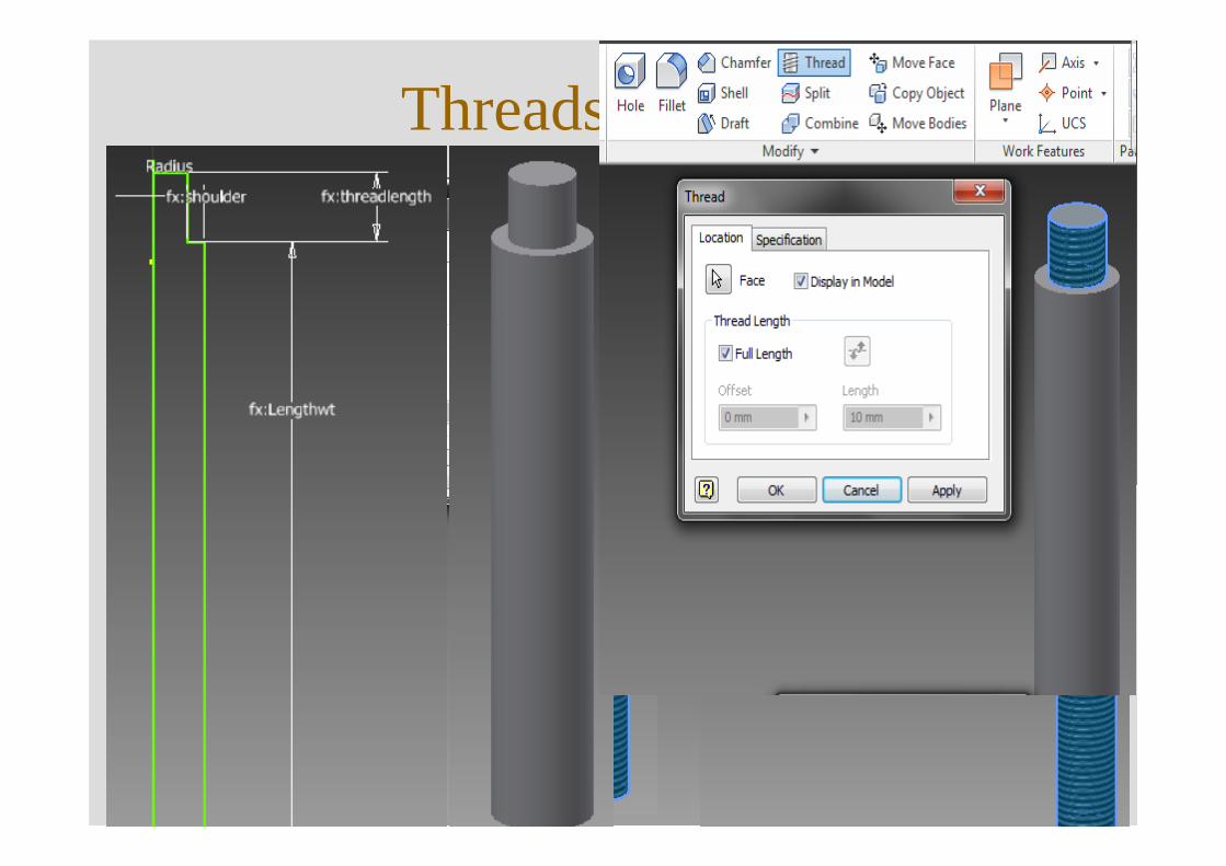
Threads
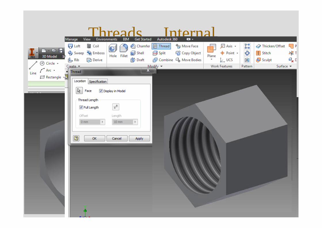
Threads… Internal
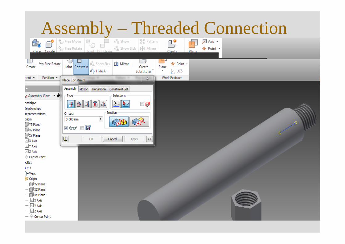
Assembly – Threaded Connection
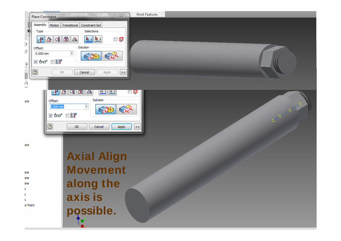
Axial AlignMovement along the axis is possible.
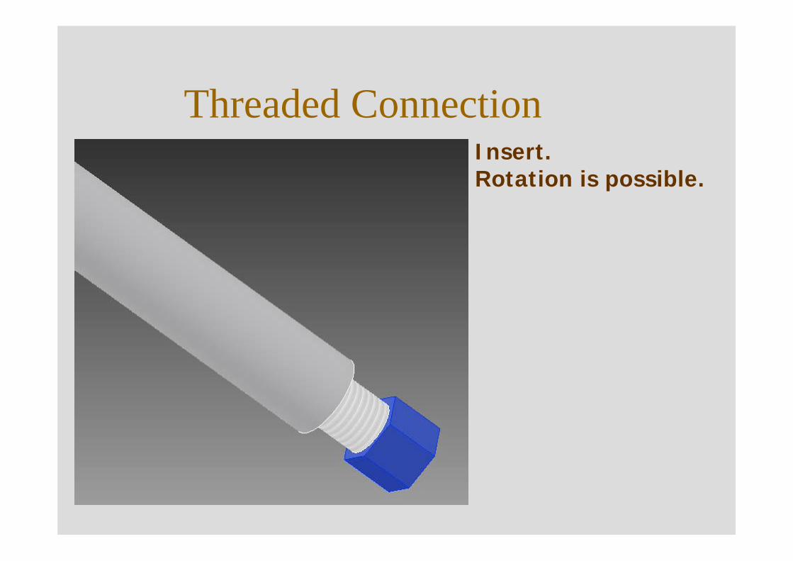
Threaded ConnectionInsert.Rotation is possible.
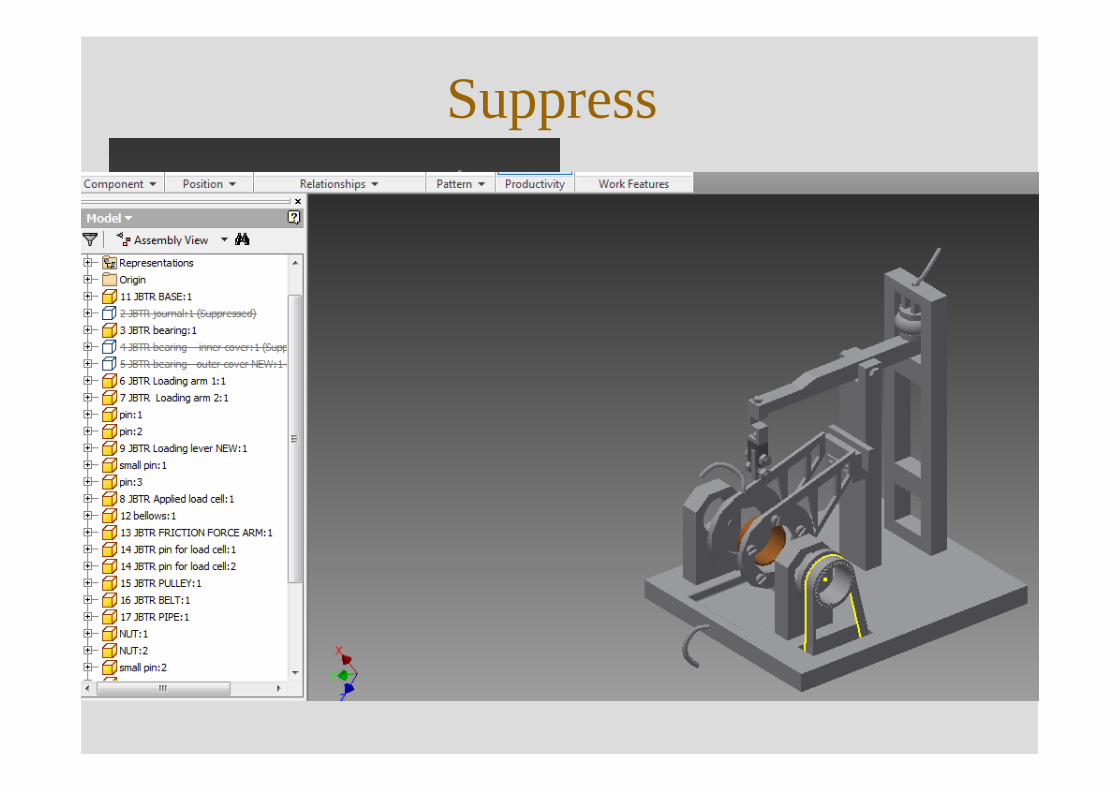
Suppress
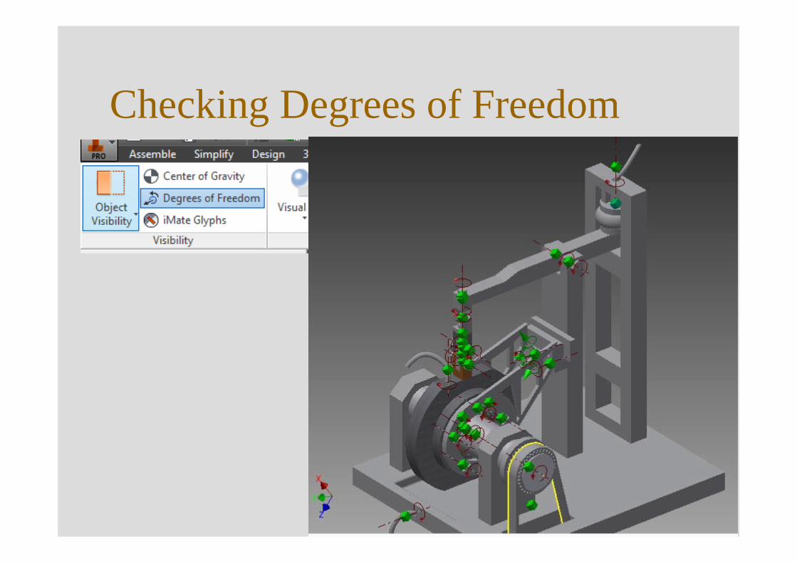
Checking Degrees of Freedom
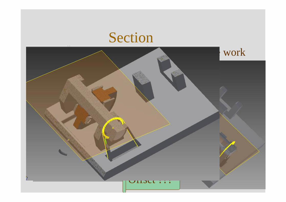
Section• Choose/Make work
feature plane.
Offset ???
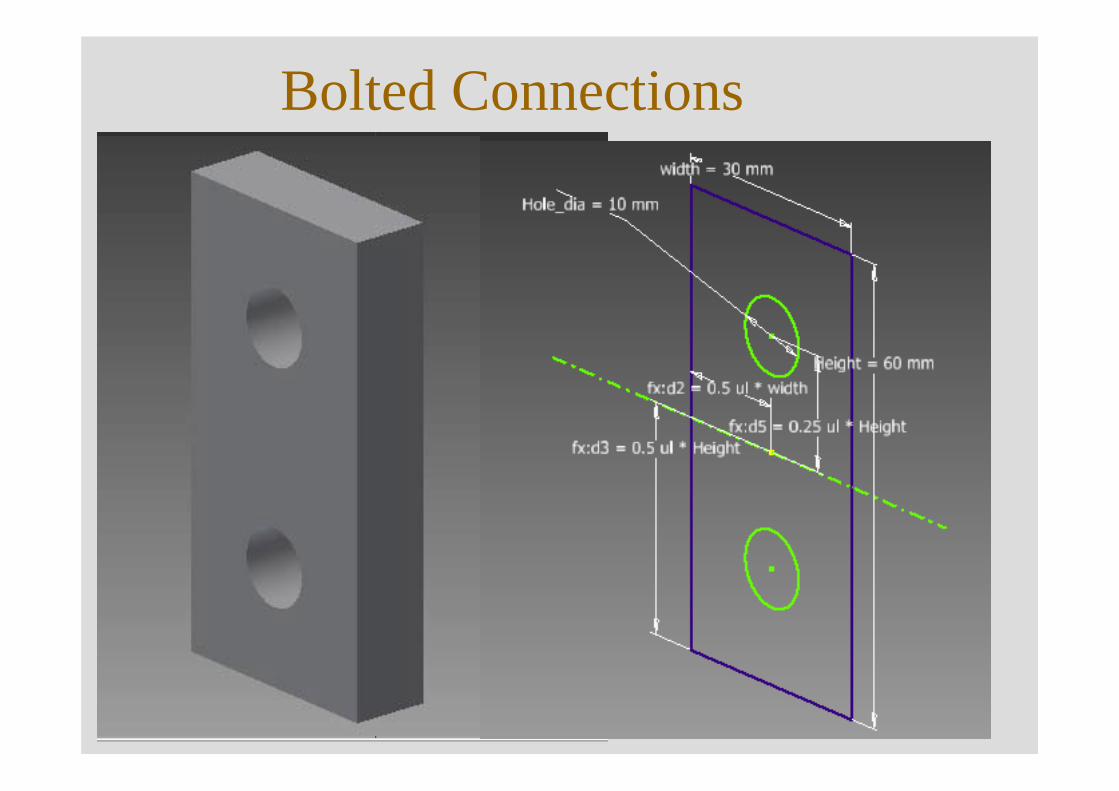
Bolted Connections
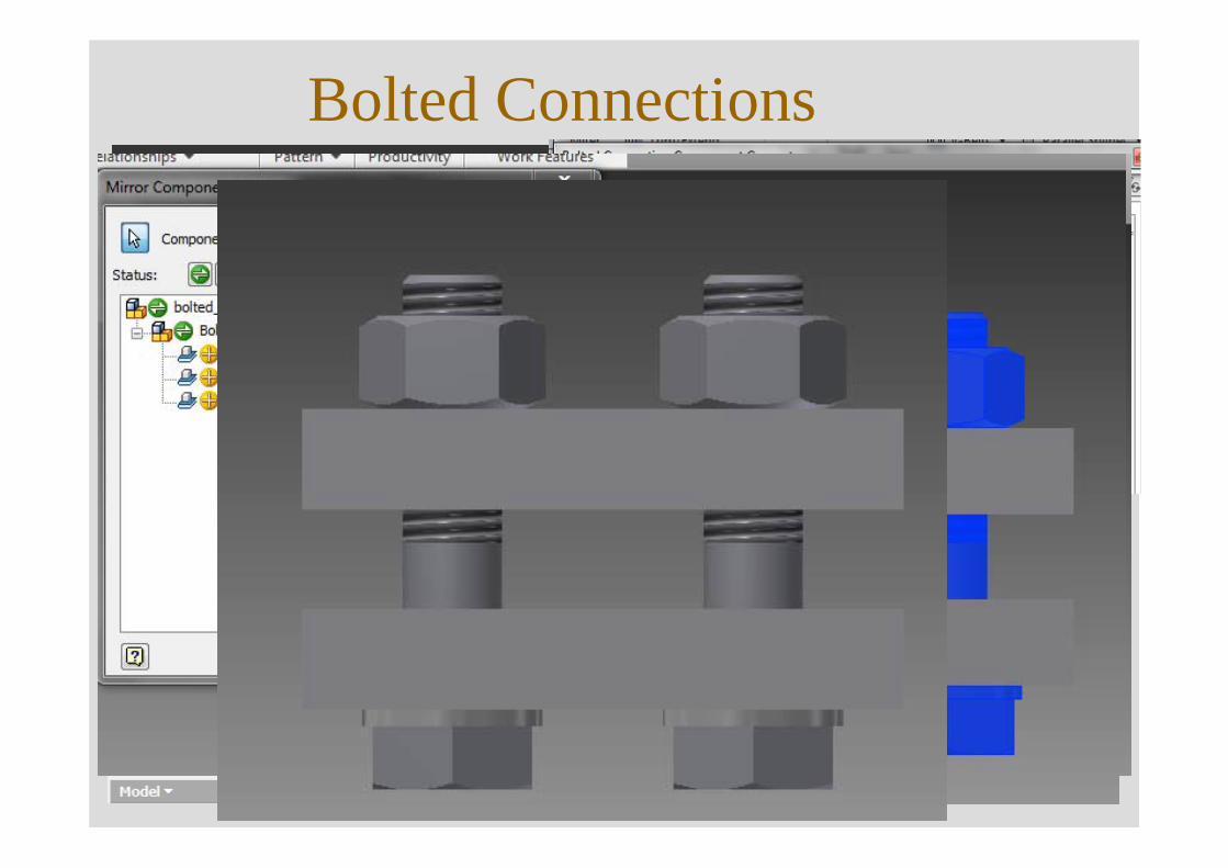
Bolted Connections
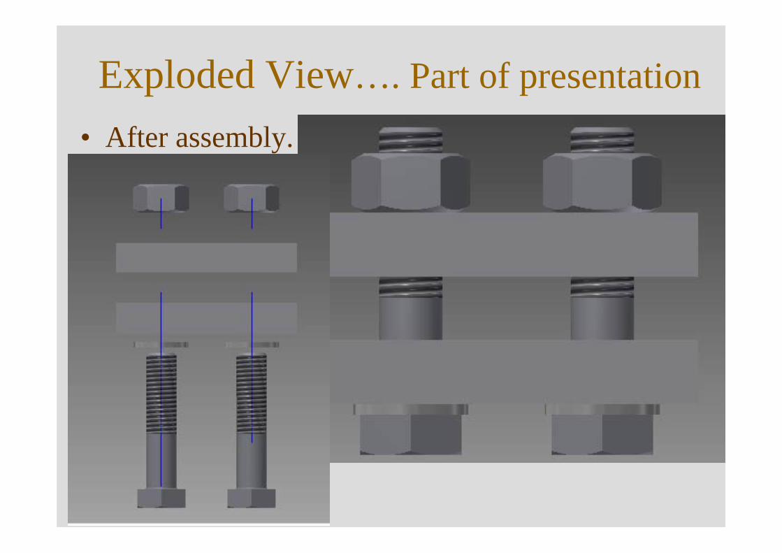
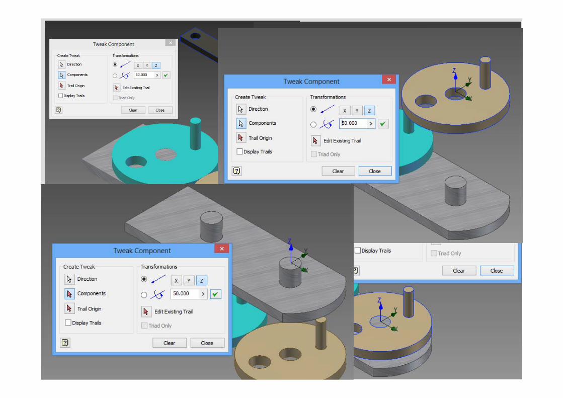
Exploded View…. Part of presentation• After assembly.
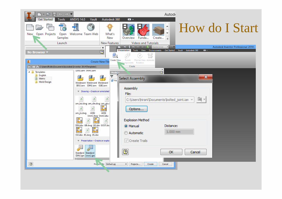
How do I Start
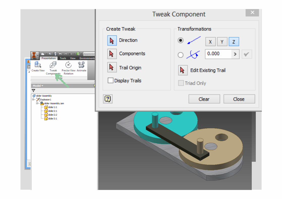
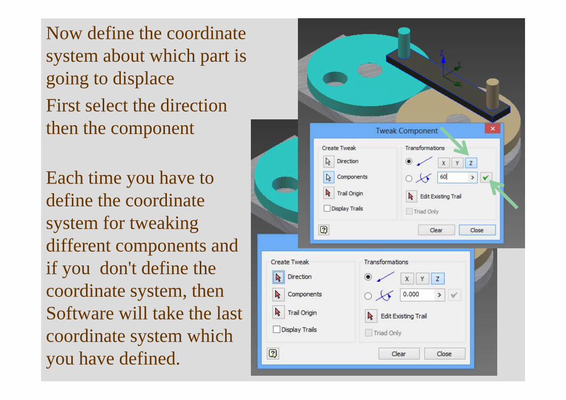
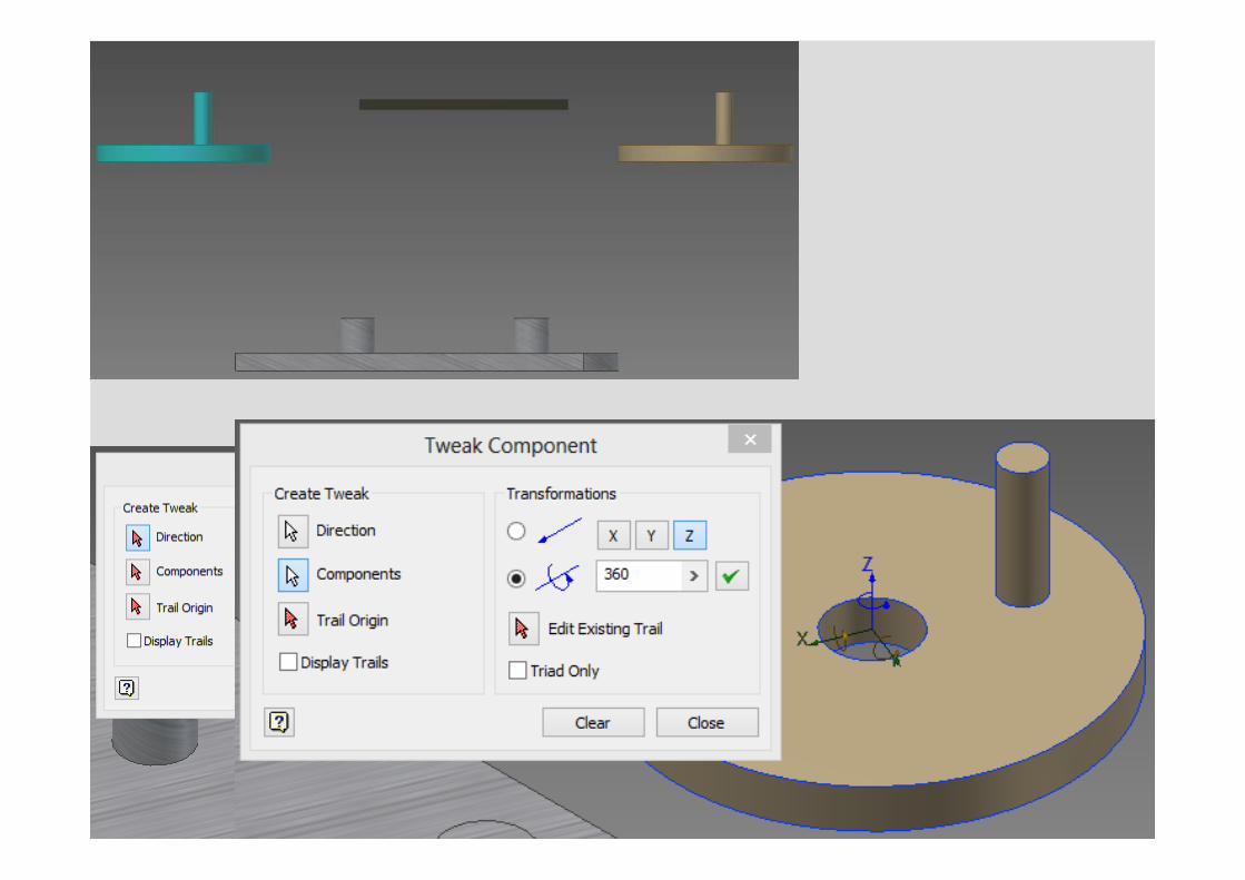
Now define the coordinate system about which part is going to displace First select the direction then the component
Each time you have to define the coordinate system for tweaking different components and if you don't define the coordinate system, then Software will take the last coordinate system which you have defined.
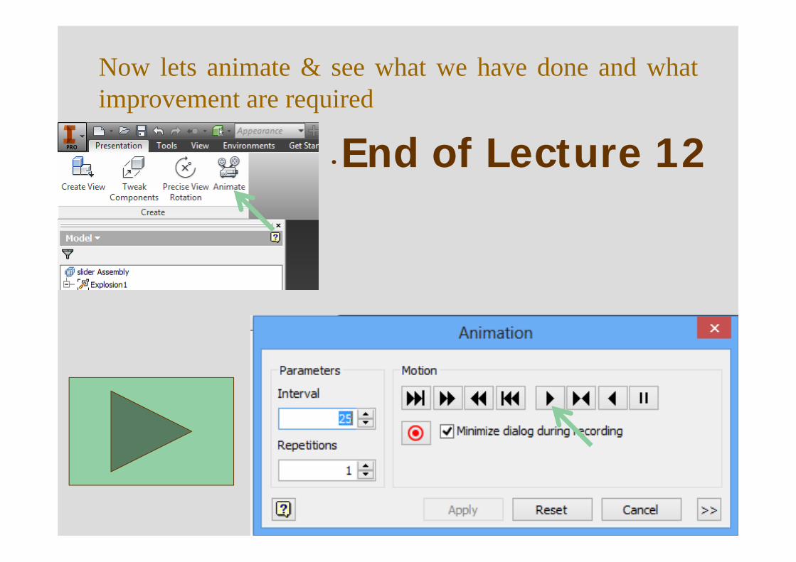
Now lets animate & see what we have done and whatimprovement are required
• End of Lecture 12