Engineered Assemblies eCatalogue 2015
459
Uniting the House of Design with the Field of Construction 7 EXTERIOR WALL PANEL AND SYSTEMS brilliant buildings Services • Design Assist • Design/Build • Drafting • Engineering • Full System Packages Products • TcLip Thermally Broken System • Equitone Fibre Cement • Parklex Wood Veneer • Vivix Solid Phenolic • Tonality Ceramic • Savoia Porcelain • IMETCO Metal Roofing, Cladding & Zinc • CPI Daylighting • SRP Breathable Membranes [email protected] 1.866.591.7021 EngineeredAssemblies.com
-
Upload
engineered-assemblies -
Category
Documents
-
view
349 -
download
17
description
Engineered Assemblies unites the house of design with the field of construction. EA offers a wide variety of contemporary facade options and sustainable subsystems. The EA eCatalogue outlines facade lines, including EQUITONE Fibre Cement, Parklex Wood Veneer, Tonality Ceramic, Fiandre Porcelain, CPI Daylighting and VIVIX Solid Phenolic. It also includes information on Engineered Assemblies' Thermally Broken Subsystem; TcLip, SRP Breathable Membranes and more. For more information on EA's products and services, contact: [email protected]
Transcript of Engineered Assemblies eCatalogue 2015

Uniting the House of Design with the Field of Construction
7ExtErior Wall
PanEl and SyStEmS
brilliant buildings
Services • Design Assist• Design/Build• Drafting• Engineering• Full System Packages
Products• TcLip Thermally Broken System• Equitone Fibre Cement• Parklex Wood Veneer• Vivix Solid Phenolic• Tonality Ceramic• Savoia Porcelain• IMETCO Metal Roofing, Cladding & Zinc• CPI Daylighting• SRP Breathable [email protected]
1.866.591.7021EngineeredAssemblies.com
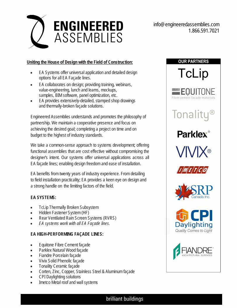
Uniting the House of Design with the Field of Construction:
• EA Systems offer universal application and detailed design options for all EA Façade lines.
• EA collaborates on design; providing training, webinars, value-engineering, lunch and learns, mockups, samples, BIM software, panel optimization, etc.
• EA provides extensively-detailed, stamped shop drawings and thermally-broken façade solutions.
Engineered Assemblies understands and promotes the philosophy of partnership. We maintain a cooperative presence and focus on achieving the desired goal; completing a project on time and on budget to the highest of industry standards.
We take a common-sense approach to systems development; offering functional assemblies that are cost effective without compromising the designer's intent. Our systems offer universal applications across all EA façade lines; enabling design freedom and ease of installation.
EA benefits from twenty years of industry experience. From detailing to field installation practicality; EA provides a keen eye on design and a strong handle on the limiting factors of the field. EA SYSTEMS: • TcLip Thermally Broken Subsystem • Hidden Fastener System (HF) • Rear Ventilated Rain Screen Systems (RVRS) • EA systems work with all EA Façade lines.
EA HIGH-PERFORMING FAÇADE LINES: • Equitone Fibre Cement façade • Parklex Natural Wood façade • Fiandre Porcelain façade • Vivix Solid Phenolic façade • Tonality Ceramic façade • Corten, Zinc, Copper, Stainless Steel & Aluminum façade • CPI Daylighting solutions • Imetco Metal roof and wall systems
[email protected] 1.866.591.7021
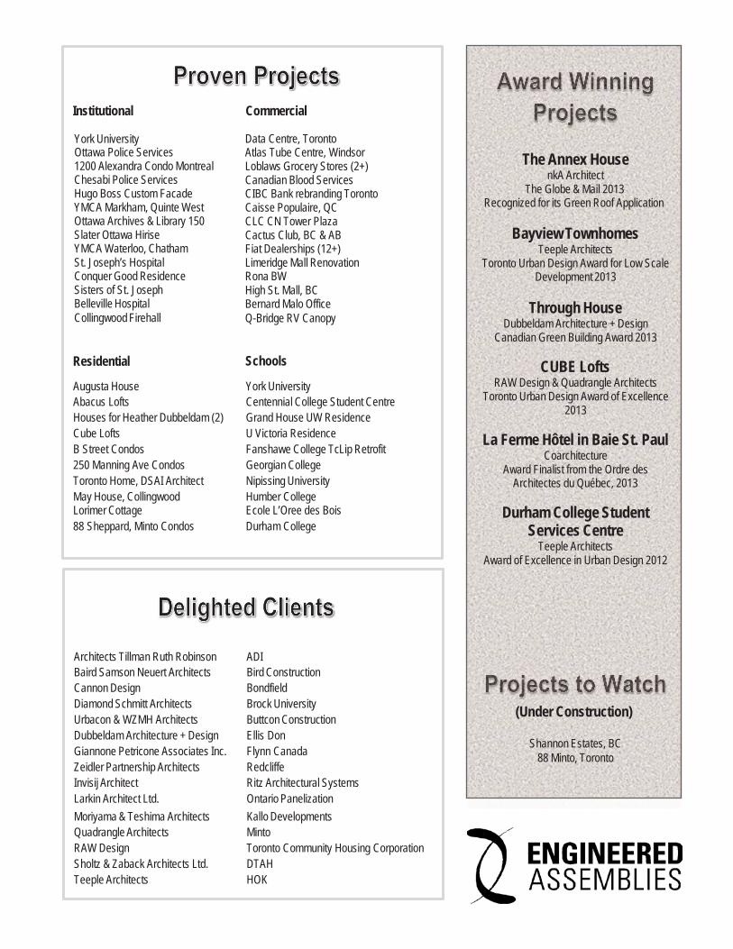
The Annex House nkA Architect
The Globe & Mail 2013Recognized for its Green Roof Application
Bayview Townhomes
Teeple Architects Toronto Urban Design Award for Low Scale
Development 2013
Through House Dubbeldam Architecture + Design
Canadian Green Building Award 2013
CUBE Lofts RAW Design & Quadrangle Architects
Toronto Urban Design Award of Excellence2013
La Ferme Hôtel in Baie St. Paul
Coarchitecture Award Finalist from the Ordre des
Architectes du Québec, 2013
Durham College StudentServices Centre
Teeple Architects Award of Excellence in Urban Design 2012
(Under Construction)
Shannon Estates, BC88 Minto, Toronto
Institutional Commercial
York University Ottawa Police Services 1200 Alexandra Condo MontrealChesabi Police Services Hugo Boss Custom FacadeYMCA Markham, Quinte WestOttawa Archives & Library 150 Slater Ottawa HiriseYMCA Waterloo, Chatham St. Joseph’s HospitalConquer Good ResidenceSisters of St. JosephBelleville HospitalCollingwood Firehall
Data Centre, Toronto Atlas Tube Centre, Windsor Loblaws Grocery Stores (2+)Canadian Blood ServicesCIBC Bank rebranding TorontoCaisse Populaire, QC CLC CN Tower Plaza Cactus Club, BC & ABFiat Dealerships (12+)Limeridge Mall RenovationRona BW High St. Mall, BCBernard Malo OfficeQ-Bridge RV Canopy
Residential Schools
Augusta House York University Abacus Lofts Centennial College Student CentreHouses for Heather Dubbeldam (2) Grand House UW ResidenceCube Lofts U Victoria Residence B Street Condos Fanshawe College TcLip Retrofit250 Manning Ave Condos Georgian College Toronto Home, DSAI Architect Nipissing University May House, Collingwood Humber College Lorimer Cottage Ecole L’Oree des Bois 88 Sheppard, Minto Condos Durham College
Architects Tillman Ruth Robinson ADI Baird Samson Neuert Architects Bird ConstructionCannon Design Bondfield Diamond Schmitt Architects Brock University Urbacon & WZMH Architects Buttcon Construction Dubbeldam Architecture + Design Ellis DonGiannone Petricone Associates Inc. Flynn Canada Zeidler Partnership Architects Redcliffe Invisij Architect Ritz Architectural Systems Larkin Architect Ltd. Ontario Panelization Moriyama & Teshima Architects Kallo DevelopmentsQuadrangle Architects Minto RAW Design Toronto Community Housing Corporation Sholtz & Zaback Architects Ltd. DTAH Teeple Architects HOK
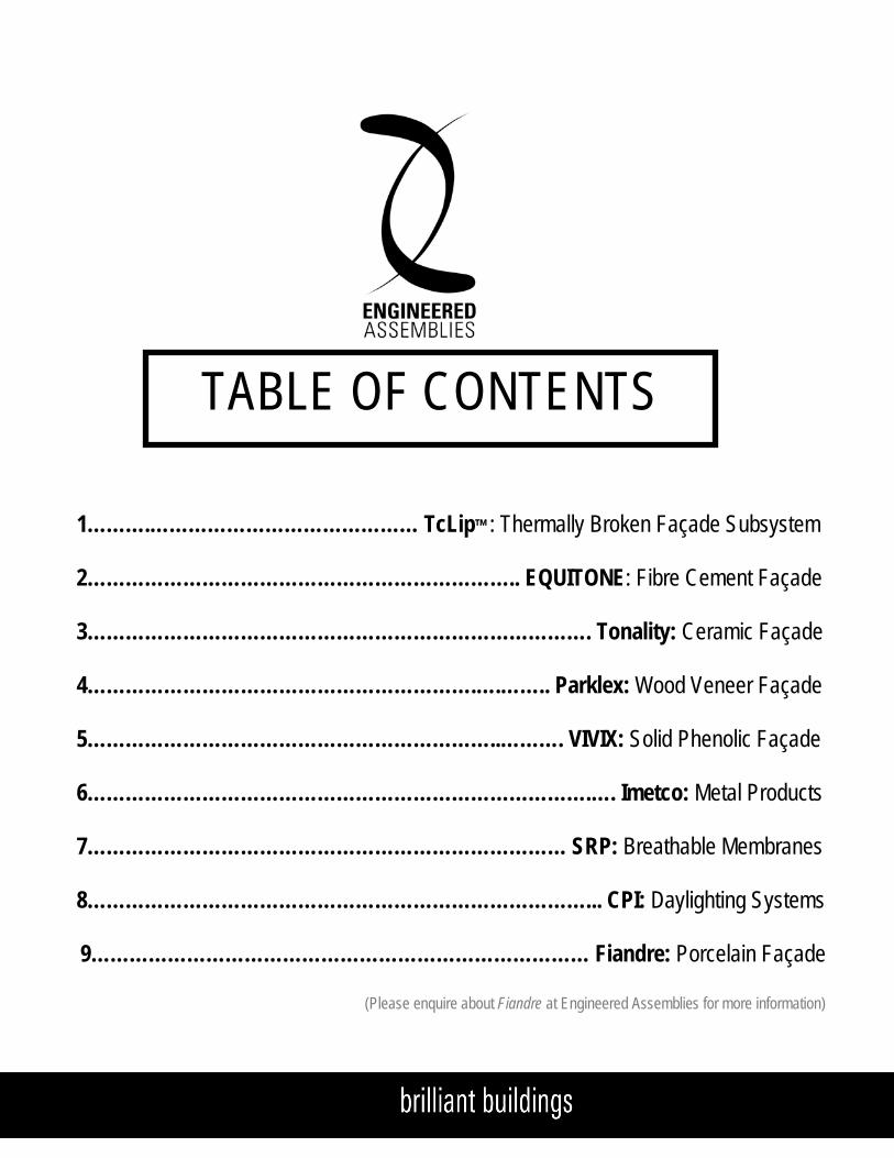
TABLE OF CONTENTS
1……….…………………………………… TcLip™: Thermally Broken Façade Subsystem
2………………………………………………………….. EQUITONE: Fibre Cement Façade
3……………………………………………………………………. Tonality: Ceramic Façade
4…………………………………………………….….…….. Parklex: Wood Veneer Façade
5………………………………………………………..………. VIVIX: Solid Phenolic Façade
6…………………………………………………………………….…. Imetco: Metal Products
7………………………………………………………………… SRP: Breathable Membranes
8……………………………………………………………………... CPI: Daylighting Systems
9…………………………………………………………………… Fiandre: Porcelain Façade
(Please enquire about Fiandre at Engineered Assemblies for more information)
Engineered Assemblies Products & Services Binder
This binder is for
REFERENCE USE ONLY
For current information on the products and services featured by Engineered Assemblies and its partners visit:
EngineeredAssemblies.com
Or Call Toll Free: 1-866-591-7021
b r i l l i a n t b u i l d i n g s
Engineered Assembl ies Inc .1.866 .591 .7021in fo@eng inee redassemb l i es .com
Version 2.0
RVRS & TcLip™ Design GuideRear Ventilated Rain Screenfor Outboard Insulated Conditions

b r i l l i a n t b u i l d i n g s
E A T c L i p ™ R V R S Wa l l S y s t e m
page 3 V 2.0
b r i l l i a n t b u i l d i n g s
E A T c L i p R V R S Wa l l S y s t e m6535 M i l l c reek D r i ve , Un i t 75M iss i ssauga , On ta r i o , Canada L5N 2M2
T 905 .816 .2218F 905 .816 .9761
E i n fo@eng inee redassemb l i es .comW Eng inee redAssemb l i es .com
page 3 APR 2014
b r i l l i a n t b u i l d i n g s
E . A . I . T h E R m A L C L I p R . V. R . S . WA L L S y S T E m6535 M i l l c reek D r i ve , Un i t 75M iss i ssauga , On ta r i o , Canada L5N 2M2
T 905 .816 .2218F 905 .816 .9761
E i n fo@eng inee redassemb l i es .comW Eng inee redAssemb l i es .com
b r i l l i a n t b u i l d i n g s
E . A . I . T h E R m A L C L I p R . V. R . S . WA L L S y S T E m6535 M i l l c reek D r i ve , Un i t 75M iss i ssauga , On ta r i o , Canada L5N 2M2
T 905 .816 .2218F 905 .816 .9761
E i n fo@eng inee redassemb l i es .comW Eng inee redAssemb l i es .com
page 303DEC13
(PATENT PENDING)
REAR VENTILATED RAIN SCREEN WITH TcLipTHERMALLY BROKEN FACADE FRAMING SYSTEM
PRODUCTS INCLUDES:FIBER REINFORCED CEMENT PANEL (FRC)EQUITONE PANELS BY EUROPANELS (formerly Eternit)
- NATURA- PICTURA- TEXTURA- TECTIVA ( formerly Eter-Color )
HIGH PRESSURED LAMINATE PANEL (HPL)
- VIVIX BY FORMICA- PARKLEX BY COMPOSITE GUREA
page 3 FEB 2014
CLAY TILE FAÇADE (CERAMIC)- TONALITY BY CREATON
PORCELAIN STONEWARE TILE FAÇADE
- PORCELAIN BY SAVOIA
HIGH PRESSURE LAMINATE PANEL (HPL)
PRODUCTS INCLUDE:
Clay Tile Façade (CeramiC)- TonaliTy by CreaTon
PorCelain SToneware Tile Façade
- PorCelain by Fiandre
HigH PreSSure laminaTe Panel (HPl)
ProduCTS inClude:
™
Fibre reinForCed CemenT Panel (FrC)

b r i l l i a n t b u i l d i n g s
E A T c L i p ™ R V R S Wa l l S y s t e m
page 4 V 2.0
b r i l l i a n t b u i l d i n g s
E A T c L i p R V R S Wa l l S y s t e m6535 M i l l c reek D r i ve , Un i t 75M iss i ssauga , On ta r i o , Canada L5N 2M2
T 905 .816 .2218F 905 .816 .9761
E i n fo@eng inee redassemb l i es .comW Eng inee redAssemb l i es .com
page 4 APR 2014
b r i l l i a n t b u i l d i n g s
E . A . I . T h E R m A L C L I p R . V. R . S . WA L L S y S T E m6535 M i l l c reek D r i ve , Un i t 75M iss i ssauga , On ta r i o , Canada L5N 2M2
T 905 .816 .2218F 905 .816 .9761
E i n fo@eng inee redassemb l i es .comW Eng inee redAssemb l i es .com
b r i l l i a n t b u i l d i n g s
E . A . I . T h E R m A L C L I p R . V. R . S . WA L L S y S T E m6535 M i l l c reek D r i ve , Un i t 75M iss i ssauga , On ta r i o , Canada L5N 2M2
T 905 .816 .2218F 905 .816 .9761
E i n fo@eng inee redassemb l i es .comW Eng inee redAssemb l i es .com
page 403DEC13
0.0 TABLE OF CONTENTS 0.1 TABLE OF CONTENTS PAGE 04
1.0 TcLip EXECUTIVE SUMMARY AND REPORTS PAGE 05-12 1.1 EXECUTIVE SUMMARY PAGE 06 1.2 QUICK REFERENCES GUIDE PAGE 07 1.3 EFFECTIVE R VALUE SELECTION GUIDE CHART PAGE 08 1.4 ISOMETRIC DETAIL PAGE 09 1.5 T100 THERMAL WALL SYSTEM DETAILS PAGE 10 1.6 T125 THERMAL WALL SYSTEM DETAILS PAGE 11 1.7 T150 THERMAL WALL SYSTEM DETAILS PAGE 12
2.0 DESIGN LOADS AND IMPORTANT DESIGN CONCEPTS PAGE 13-23 2.1 DESIGN LOADS PAGE 13 2.2 HATBAR LOCATION ( FASTENING POINTS TABLE) PAGE 14 2.3 RAIN-SCREEN DESIGN FOR PLENUM INTEGRITY, DRAINAGE AND VENTING PAGE 15 2.4 VERTICAL SECTION FOR THE ‘T100’ CLIP THERMAL SYSTEM PAGE 16-17 2.5 VERTICAL SECTION FOR THE ‘T125’ CLIP THERMAL SYSTEM PAGE 18-19 2.6 VERTICAL SECTION FOR THE ‘T150’ CLIP THERMAL SYSTEM PAGE 20-21 2.7 PLAN SECTION AT ALIGNED VERTICAL JOINTS PAGE 22 2.8 PLAN SECTION AT STAGGERD VERTICAL JOINTS PAGE 23
3.0 DETAILING FOR PANEL MOVEMENT AND LOCK POINTS PAGE 24-31 3.1 RIVET SETTING DETAIL AND NOTES PAGE 24 3.2 INTERMEDIATE SUPPORTS AT SLIDING POINTS PAGE 25 3.3 INTERMEDIATE SUPPORTS AT FIXED POINTS PAGE 25 3.4 FIBER CEMENT BOARD FASTENER LAYOUTS FOR VERTICAL PANEL
3.5 FIBER CEMENT BOARD FASTENER LAYOUTS FOR HORIZONTAL PANEL PAGE 26
3.6 PARKLEX FASTENER LAYOUTS FOR VERTICAL PANEL
PAGE 27
3.7 PARKLEX FASTENER LAYOUTS FOR HORIZONTAL PANEL PAGE 28
PAGE 39 3.8 VIVIX BOARD FASTENER LAYOUTS FOR HORIZONTAL PANEL PAGE 30
3.9 VIVIX BOARD FASTENER LAYOUTS FOR VERTICAL PANEL PAGE 31
4.0 DETAILING FOR CONTROL JOINT MOVEMENT PAGE 32-33 4.1 THERMAL EFFECTS – STEEL VS ALUMINUM PAGE 32 4.2 CONTROL JOINTS IN THE BUILDING STRUCTURE (AREAS REQUIRING ATTENTION) PAGE 32 4.3 DETAIL AT ACTIVE CONTROL JOINTS PAGE 33
5.0 TYPICAL DETAILS FOR E.A.I. R.V.R.S. FACADE SYSTEM PAGE 34-48 5.1 DETAIL REFERENCE PAGE 34 5.2 DETAIL AT ACTIVE CONTROL JOINTS PAGE 35 5.3 VERTICAL SECTION AT CLOSED HORIZONTAL JOINT PAGE 36 5.4 SECTION DETAIL AT WALL BASE PAGE 37 5.5 HEAD SECTION DETAIL AT OPENING GREATER THAN 2M PAGE 38 5.6 SILL SECTION DETAIL AT OPENING GREATER THAN 2M PAGE 39 5.7 HEAD SECTION DETAIL AT OPENING LESS THAN 2M PAGE 40 5.8 SILL SECTION DETAIL AT OPENING LESS THAN 2M PAGE 41 5.9 PLAN DETAIL – AT TYPICAL OPENING PAGE 42 5.10 PLAN DETAIL – OUTSIDE CORNER PAGE 43 5.11 PLAN DETAIL – INSIDE CORNER PAGE 44 5.12 PLAN DETAIL – TO WALL END PAGE 45 5.13 PLAN DETAIL – SOFFIT AT FASCIA PAGE 46 5.14 PLAN DETAIL – SOFFIT AT WALLS PAGE 47 5.15 ISOMETRIC DETAIL PAGE 48
6.0 E.A.I SYSTEMS PART SPECIFICATION PAGE 49-537.0 IMPORTANT FIELD ERECTION NOTES PAGE 548.0 TRANSPORTATION, STORAGE AND PANEL CUTTING PAGE 55-569.0 TOOLS AVAILABLE FROM ENGINEERED ASSEMBLIES AND STANDARD PARTS PAGE 57-60
page 4 FEB 2014
page 4 APR 2014
page 4 aPr 2014
™ EXECUTIVE SUMMARY AND REPORTS
FIBREFIBRE
b r i l l i a n t b u i l d i n g s
E A T c L i p ™ R V R S Wa l l S y s t e m
page 5 V 2.0
b r i l l i a n t b u i l d i n g s
E . A . I . T h E r m A l C l I p r . V. r . S . WA l l S y S T E mEngineered Assembl ies Inc .6535 M i l l c reek D r i ve , Un i t 75M iss i ssauga , On ta r i o , Canada L5N 2M2
T 905 .816 .2218F 905 .816 .9761
E i n fo@eng inee redassemb l i es .comW Eng inee redAssemb l i es .com
page 303DEC13
We are pleased to provide you thermal and structural testing and analysis for TClip; Thermally Broken Subsystem for use with a variety of facades including: fibre cement, solid phenolic, ceramic, wood veneer, porcelain, etc.
INTRODUCTIONThis guide provides thermal and structural analysis of Engineered Assemblies’ TClip; Thermally Broken Subsystem. The TClip system supports a variety of façade panels. The main purpose of this guide is to create a better understanding of the performance capabilities and benefits of TClip.
Refer to the “Quick References” section of this guide for a breakdown of performance details and system drawings. System drawings 1, 2 and 3 (pgs. 8-10) detail Engineered Assemblies Hidden Fastening system.
DISCLAIMERThe use of this information shows your acceptance of these terms. The information is intended to provide background information on Engineered Assemblies building envelope systems; specifically TClip; Thermally Broken Subsystem with reference to the Hidden Fastener System.
Although Engineered Assemblies Inc. makes reasonable efforts to present information which is up to date and accurate. Engineered Assemblies Inc. makes no representation or warranty as to the adequacy, accuracy completeness or correctness of such information, nor does it warrant or represent that the information provided is complete in every respect.
Engineered Assemblies Inc. shall not have liability resulting from the use of the information provided, the absence of any specific information, the possible interruptions or technical errors of this information and/or the content herein.
Your Engineered Assemblies Inc. Team
Engineered Assemblies Inc. 6535 Millcreek Drive, Unit 75 Mississauga, Ontario, Canada L5N 2M2 T 905.816.2218 F 905.816.9761 E [email protected] W EngineeredAssemblies.com
Experience Success through Partnership with our Services: • We collaborate on design; providing value engineering, mockups,
samples, lunch and learns, webinars, etc. • We provide extensively-detailed, stamped shop drawings. • We offer complete system supply. Engineered Assemblies understands and promotes the philosophy of partnership. We maintain a cooperative presence and focus on achieving the desired goal; completing a project on time and on budget to the highest of industry standards. We take a common-sense approach to systems development; offering functional assemblies that are cost effective without compromising the designer's intent. From detailing to field installation practicality, our 20 years of experience provide a keen eye on the design and strong handle on the limiting factors of the field. OUR SYSTEMS: • TcLip Thermally Broken Subsystem • Hidden Fastener System (HF) • Rear Ventilated Rain Screen Systems (RVRS) OUR PRODUCTS: • Equitone Fibre Cement façade • Parklex Natural Wood façade • Savoia Porcelain façade • Tonality Ceramic façade • VIVIX Solid Phenolic façade • Corten, Zinc, Copper, Stainless Steel & Aluminum façade • CPI Daylighting solutions • Imetco Metal roof and wall systems
Engineered Assemblies Unites the House of Design
to The Field of Construction
OUR PARTNERS
we are pleased to provide you with some of our Thermally broken rVrS System details.
INTRODUCTIONThis manual provides information and instructions for steps required to supply a quality façade installation of rVrS systems. The main purpose of this guide is to create a better understanding of how to properly design, detail, dimension and install the TCliP rVrS system.
DISCLAIMERThe use of this information shows your acceptance of these terms.The information is intended to provide background information on Façade products provided by engineered assemblies inc. although engineered assemblies inc. makes reasonable efforts to present information which is up to date and accurate. engineered assemblies inc. makes no representation or warranty as to the adequacy, accuracycompleteness or correctness of such information, nor does it warrant or represent that the information provided is complete in every respect.engineered assemblies inc. shall not have liability resulting from the use of the information provided, the absence of any specific information, the possible interruptions or technical errors of this information and/orthe content herein.
Your Engineered Assemblies Inc. Team
™
b r i l l i a n t b u i l d i n g s
E A T c L i p ™ R V R S Wa l l S y s t e m
page 6 V 2.0
b r i l l i a n t b u i l d i n g s
E A T c L i p R V R S Wa l l S y s t e m6535 M i l l c reek D r i ve , Un i t 75M iss i ssauga , On ta r i o , Canada L5N 2M2
T 905 .816 .2218F 905 .816 .9761
E i n fo@eng inee redassemb l i es .comW Eng inee redAssemb l i es .com
page 6 APR 2014
b r i l l i a n t b u i l d i n g s
E . A . I . T h E R m A L C L I p R . V. R . S . WA L L S y S T E m6535 M i l l c reek D r i ve , Un i t 75M iss i ssauga , On ta r i o , Canada L5N 2M2
T 905 .816 .2218F 905 .816 .9761
E i n fo@eng inee redassemb l i es .comW Eng inee redAssemb l i es .com
b r i l l i a n t b u i l d i n g s
E . A . I . T h E R m A L C L I p R . V. R . S . WA L L S y S T E m6535 M i l l c reek D r i ve , Un i t 75M iss i ssauga , On ta r i o , Canada L5N 2M2
T 905 .816 .2218F 905 .816 .9761
E i n fo@eng inee redassemb l i es .comW Eng inee redAssemb l i es .com
page 603DEC13
Engineered Assemblies Inc.6535 Millcreek Drive, Unit 75Mississauga, ontario, Canadal5n 2M2
T 905.816.2218f 905.816.9761
e [email protected] engineeredassemblies.com
june 21, 2012
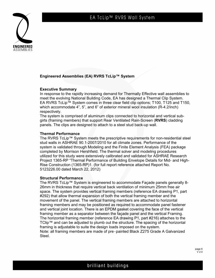
Engineered Assemblies (EA) RVRS TcLip™ System
Executive SummaryIn response to the rapidly increasing demand for Thermally Effective wall assemblies to meet the evolving National Building Code, EA has designed a Thermal Clip System. EA RVRS TcLip™ System comes in three clear field clip options; T100, T125 and T150, which accommodate 4”, 5”, and 6” of exterior mineral wool insulation (R-4.2/inch) respectively. The system is comprised of aluminum clips connected to horizontal and vertical sub-girts (framing members) that support Rear Ventilated Rain-Screen (RVRS) cladding panels. The clips are designed to attach to a steel stud back-up wall. Thermal Performance The RVRS TcLip™ System meets the prescriptive requirements for non-residential steel stud walls in ASHRAE 90.1-2007/2010 for all climate zones. Performance of the system is validated through Modeling and the Finite Element Analysis (FEA) package completed by Morrison Hershfield. The thermal solver and modeling procedures utilized for this study were extensively calibrated and validated for ASHRAE Research Project 1365-RP “Thermal Performance of Building Envelope Details for Mid- and High-Rise Construction (1365-RP)1. (for full report reference attached Report No. 5123226.00 dated March 22, 2012) Structural PerformanceThe RVRS TcLip™ System is engineered to accommodate Façade panels generally 8-26mm in thickness that require vertical back ventilation of minimum 25mm free air space. The system provides vertical framing members (reference EA drawing P1, part #292) that allow thermal expansion of both the vertical framing member and the movement of the panel. The vertical framing members are attached to horizontal framing members and may be positioned as required to accommodate panel fastener and vertical joint location. There is an EPDM gasket covering the face of the vertical framing member as a separator between the façade panel and the vertical Framing. The horizontal framing member (reference EA drawing P1, part #216) attaches to the TClip™ and can be adjusted to plumb out the structure. The spacing of the horizontal framing is adjustable to suite the design loads imposed on the system. Note: all framing members are made of pre=painted Black Z275 Grade A Galvanized Steel. RVRS TcLip™ design
page 6 FEB 2014
-
b r i l l i a n t b u i l d i n g s
E A T c L i p ™ R V R S Wa l l S y s t e m
page 7 V 2.0
b r i l l i a n t b u i l d i n g s
E A T c L i p R V R S Wa l l S y s t e m6535 M i l l c reek D r i ve , Un i t 75M iss i ssauga , On ta r i o , Canada L5N 2M2
T 905 .816 .2218F 905 .816 .9761
E i n fo@eng inee redassemb l i es .comW Eng inee redAssemb l i es .com
page 7 APR 2014
6535 M i l l c reek D r i ve , Un i t 75M iss i ssauga , On ta r i o , Canada L5N 2M2
T 905 .816 .2218F 905 .816 .9761
E i n fo@eng inee redassemb l i es .comW Eng inee redAssemb l i es .com
b r i l l i a n t b u i l d i n g s
E . A . I . T h E R m A L C L I p R . V. R . S . WA L L S y S T E m6535 M i l l c reek D r i ve , Un i t 75M iss i ssauga , On ta r i o , Canada L5N 2M2
T 905 .816 .2218F 905 .816 .9761
E i n fo@eng inee redassemb l i es .comW Eng inee redAssemb l i es .com
b r i l l i a n t b u i l d i n g s
E . A . I . T h E R m A L C L I p R . V. R . S . WA L L S y S T E m6535 M i l l c reek D r i ve , Un i t 75M iss i ssauga , On ta r i o , Canada L5N 2M2
T 905 .816 .2218F 905 .816 .9761
E i n fo@eng inee redassemb l i es .comW Eng inee redAssemb l i es .com
page 703DEC13
November 18, 2013page 2 of 2
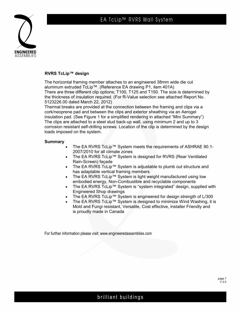
The horizontal framing member attaches to an engineered 38mm wide die cut aluminum extruded TcLip™. (Reference EA drawing P1, item 401A) There are three different clip options; T100, T125 and T150. The size is determined by the thickness of insulation required. (For R-Value selection see attached Report No. 5123226.00 dated March 22, 2012) Thermal breaks are provided at the connection between the framing and clips via a cork/neoprene pad and between the clips and exterior sheathing via an Aerogel insulation pad. (See Figure 1 for a simplified rendering in attached “Mini Summary”) The clips are attached to a steel stud back-up wall, using minimum 2 and up to 3 corrosion resistant self-drilling screws. Location of the clip is determined by the design loads imposed on the system. Summary
• The EA RVRS TcLip™ System meets the requirements of ASHRAE 90.1-2007/2010 for all climate zones
• The EA RVRS TcLip™ System is designed for RVRS (Rear Ventilated Rain-Screen) façade
• The EA RVRS TcLip™ System is adjustable to plumb out structure and has adaptable vertical framing members
• The EA RVRS TcLip™ System is light weight manufactured using low embodied energy, Non-Combustible and recyclable components
• The EA RVRS TcLip™ System is “system integrated” design, supplied with Engineered Shop drawings
• The EA RVRS TcLip™ System is engineered for design strength of L/300 • The EA RVRS TcLip™ System is designed to minimize Wind Washing, it is
Mold and Fungi resistant, Versatile, Cost effective, installer Friendly and is proudly made in Canada
for further information please visit: www.engineeredassemblies.com
Engineered Assemblies Inc.6535 Millcreek Drive, Unit 75Mississauga, ontario, Canadal5n 2M2
T 905.816.2218f 905.816.9761
e [email protected] engineeredassemblies.com
june 21, 2012
Engineered Assemblies (EA) RVRS TClip System
Executive SummaryIn response to the rapidly increasing demand for Thermally Effective wall assemblies to meet the evolving National Building Code, EA has designed a Thermal Clip System. EA RVRS T-Clip System comes in three clear field clip options; T100, T125 and T150, which accommodate 4”, 5”, and 6” of exterior mineral wool insulation (R-4.2/inch) respectively. The system is comprised of aluminum clips connected to horizontal and vertical sub-girts (framing members) that support Rear Ventilated Rain-Screen (RVRS) cladding panels. The clips are designed to attach to a steel stud back-up wall. Thermal Performance The RVRS TClip System meets the prescriptive requirements for non-residential steel stud walls in ASHRAE 90.1-2007/2010 for all climate zones. Performance of the system is validated through Modeling and the Finite Element Analysis (FEA) package completed by Morrison Hershfield. The thermal solver and modeling procedures utilized for this study were extensively calibrated and validated for ASHRAE Research Project 1365-RP “Thermal Performance of Building Envelope Details for Mid- and High-Rise Construction (1365-RP)1. (for full report reference attached Report No. 5123226.00 dated March 22, 2012) Structural PerformanceThe RVRS TClip System is engineered to accommodate Façade panels generally 8-26mm in thickness that require vertical back ventilation of minimum 25mm free air space. The system provides vertical framing members (reference EA drawing P1, part #292) that allow thermal expansion of both the vertical framing member and the movement of the panel. The vertical framing members are attached to horizontal framing members and may be positioned as required to accommodate panel fastener and vertical joint location. There is an EPDM gasket covering the face of the vertical framing member as a separator between the façade panel and the vertical Framing. The horizontal framing member (reference EA drawing P1, part #216) attaches to the TClip and can be adjusted to plumb out the structure. The spacing of the horizontal framing is adjustable to suite the design loads imposed on the system. Note: all framing members are made of pre=painted Black Z275 Grade A Galvanized Steel. RVRS TClip design
page 7 FEB 2014
RVRS TcLip designRVRS TcLip design
b r i l l i a n t b u i l d i n g s
E A T c L i p R V R S Wa l l S y s t e m6535 M i l l c reek D r i ve , Un i t 75M iss i ssauga , On ta r i o , Canada L5N 2M2
T 905 .816 .2218F 905 .816 .9761
E i n fo@eng inee redassemb l i es .comW Eng inee redAssemb l i es .com
page 6 APR 2014
b r i l l i a n t b u i l d i n g s
E . A . I . T h E R m A L C L I p R . V. R . S . WA L L S y S T E m6535 M i l l c reek D r i ve , Un i t 75M iss i ssauga , On ta r i o , Canada L5N 2M2
T 905 .816 .2218F 905 .816 .9761
E i n fo@eng inee redassemb l i es .comW Eng inee redAssemb l i es .com
b r i l l i a n t b u i l d i n g s
E . A . I . T h E R m A L C L I p R . V. R . S . WA L L S y S T E m6535 M i l l c reek D r i ve , Un i t 75M iss i ssauga , On ta r i o , Canada L5N 2M2
T 905 .816 .2218F 905 .816 .9761
E i n fo@eng inee redassemb l i es .comW Eng inee redAssemb l i es .com
page 603DEC13
Engineered Assemblies Inc.6535 Millcreek Drive, Unit 75Mississauga, ontario, Canadal5n 2M2
T 905.816.2218f 905.816.9761
e [email protected] engineeredassemblies.com
june 21, 2012
Engineered Assemblies (EA) RVRS TcLip™ System
Executive SummaryIn response to the rapidly increasing demand for Thermally Effective wall assemblies to meet the evolving National Building Code, EA has designed a Thermal Clip System. EA RVRS TcLip™ System comes in three clear field clip options; T100, T125 and T150, which accommodate 4”, 5”, and 6” of exterior mineral wool insulation (R-4.2/inch) respectively. The system is comprised of aluminum clips connected to horizontal and vertical sub-girts (framing members) that support Rear Ventilated Rain-Screen (RVRS) cladding panels. The clips are designed to attach to a steel stud back-up wall. Thermal Performance The RVRS TcLip™ System meets the prescriptive requirements for non-residential steel stud walls in ASHRAE 90.1-2007/2010 for all climate zones. Performance of the system is validated through Modeling and the Finite Element Analysis (FEA) package completed by Morrison Hershfield. The thermal solver and modeling procedures utilized for this study were extensively calibrated and validated for ASHRAE Research Project 1365-RP “Thermal Performance of Building Envelope Details for Mid- and High-Rise Construction (1365-RP)1. (for full report reference attached Report No. 5123226.00 dated March 22, 2012) Structural PerformanceThe RVRS TcLip™ System is engineered to accommodate Façade panels generally 8-26mm in thickness that require vertical back ventilation of minimum 25mm free air space. The system provides vertical framing members (reference EA drawing P1, part #292) that allow thermal expansion of both the vertical framing member and the movement of the panel. The vertical framing members are attached to horizontal framing members and may be positioned as required to accommodate panel fastener and vertical joint location. There is an EPDM gasket covering the face of the vertical framing member as a separator between the façade panel and the vertical Framing. The horizontal framing member (reference EA drawing P1, part #216) attaches to the TClip™ and can be adjusted to plumb out the structure. The spacing of the horizontal framing is adjustable to suite the design loads imposed on the system. Note: all framing members are made of pre=painted Black Z275 Grade A Galvanized Steel. RVRS TcLip™ design
page 6 FEB 2014
b r i l l i a n t b u i l d i n g s
E A T c L i p ™ R V R S Wa l l S y s t e m
page 8 V 2.0
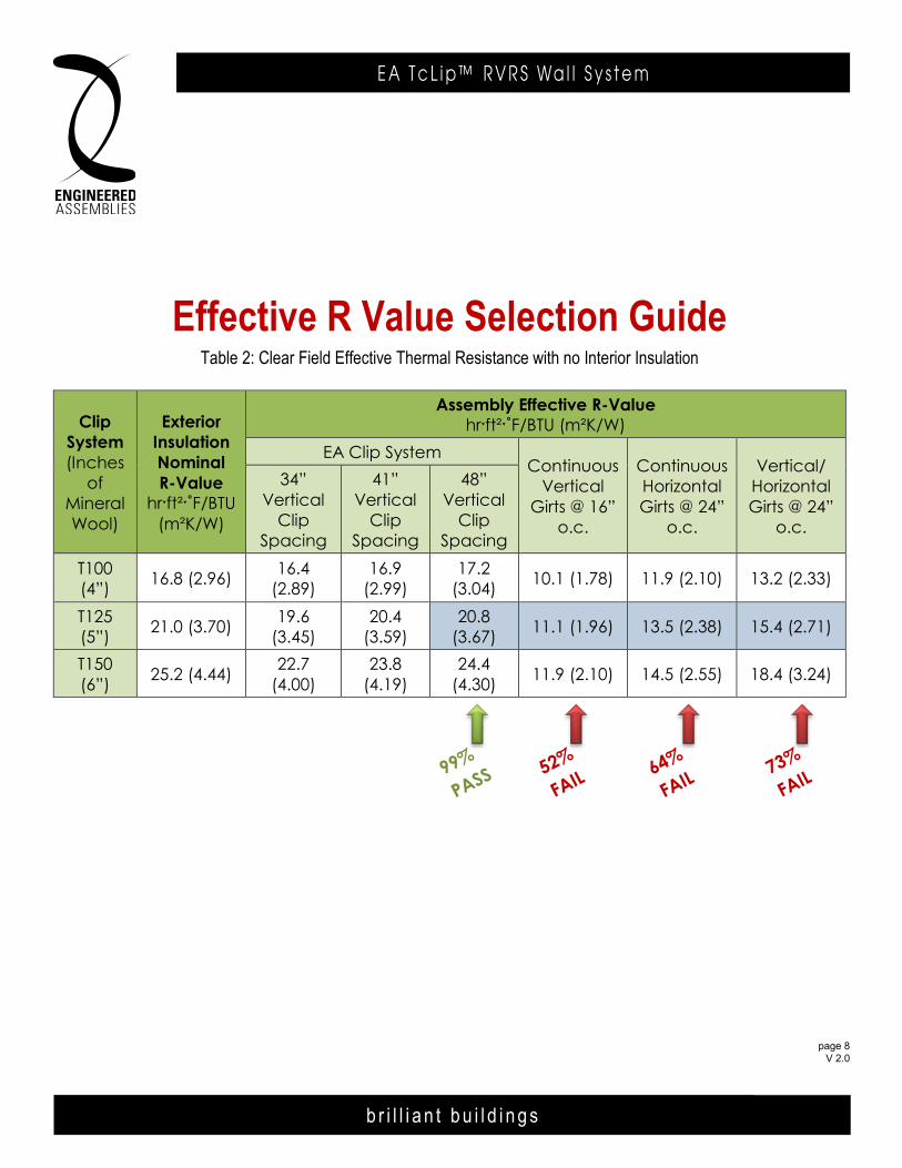
Effective R Value Selection GuideTable 2: Clear Field Effective Thermal Resistance with no Interior Insulation
Clip System(Inches
of Mineral Wool)
Exterior Insulation Nominal R-Value
hrˑft²ˑ˚F/BTU(m²K/W)
Assembly Effective R-Valuehrˑft²ˑ˚F/BTU (m²K/W)
EA Clip SystemContinuous
Vertical Girts @ 16”
o.c.
Continuous Horizontal Girts @ 24”
o.c.
Vertical/HorizontalGirts @ 24”
o.c.
34”Vertical
Clip Spacing
41”Vertical
Clip Spacing
48”Vertical
Clip Spacing
T100(4”) 16.8 (2.96) 16.4
(2.89)16.9
(2.99)17.2
(3.04) 10.1 (1.78) 11.9 (2.10) 13.2 (2.33)
T125(5”) 21.0 (3.70) 19.6
(3.45)20.4
(3.59)20.8
(3.67) 11.1 (1.96) 13.5 (2.38) 15.4 (2.71)
T150(6”) 25.2 (4.44) 22.7
(4.00)23.8
(4.19)24.4
(4.30) 11.9 (2.10) 14.5 (2.55) 18.4 (3.24)
b r i l l i a n t b u i l d i n g s
E A T c L i p ™ R V R S Wa l l S y s t e m
page 9 V 2.0
b r i l l i a n t b u i l d i n g s
E A T c L i p R V R S Wa l l S y s t e m6535 M i l l c reek D r i ve , Un i t 75M iss i ssauga , On ta r i o , Canada L5N 2M2
T 905 .816 .2218F 905 .816 .9761
E i n fo@eng inee redassemb l i es .comW Eng inee redAssemb l i es .com
page 9 APR 2014
6535 M i l l c reek D r i ve , Un i t 75M iss i ssauga , On ta r i o , Canada L5N 2M2
T 905 .816 .2218F 905 .816 .9761
E i n fo@eng inee redassemb l i es .comW Eng inee redAssemb l i es .com
b r i l l i a n t b u i l d i n g s
E . A . I . T h E R m A L C L I p R . V. R . S . WA L L S y S T E m6535 M i l l c reek D r i ve , Un i t 75M iss i ssauga , On ta r i o , Canada L5N 2M2
T 905 .816 .2218F 905 .816 .9761
E i n fo@eng inee redassemb l i es .comW Eng inee redAssemb l i es .com
b r i l l i a n t b u i l d i n g s
E . A . I . T h E R m A L C L I p R . V. R . S . WA L L S y S T E m6535 M i l l c reek D r i ve , Un i t 75M iss i ssauga , On ta r i o , Canada L5N 2M2
T 905 .816 .2218F 905 .816 .9761
E i n fo@eng inee redassemb l i es .comW Eng inee redAssemb l i es .com
page 903DEC13
b r i l l i a n t b u i l d i n g s
E . A . I . T h E R m A L C L I p R . V. R . S . WA L L S y S T E mEngineered Assembl ies Inc .6535 M i l l c reek D r i ve , Un i t 75M iss i ssauga , On ta r i o , Canada L5N 2M2
T 905 .816 .2218F 905 .816 .9761
E i n fo@eng inee redassemb l i es .comW Eng inee redAssemb l i es .com
page 718NOV13
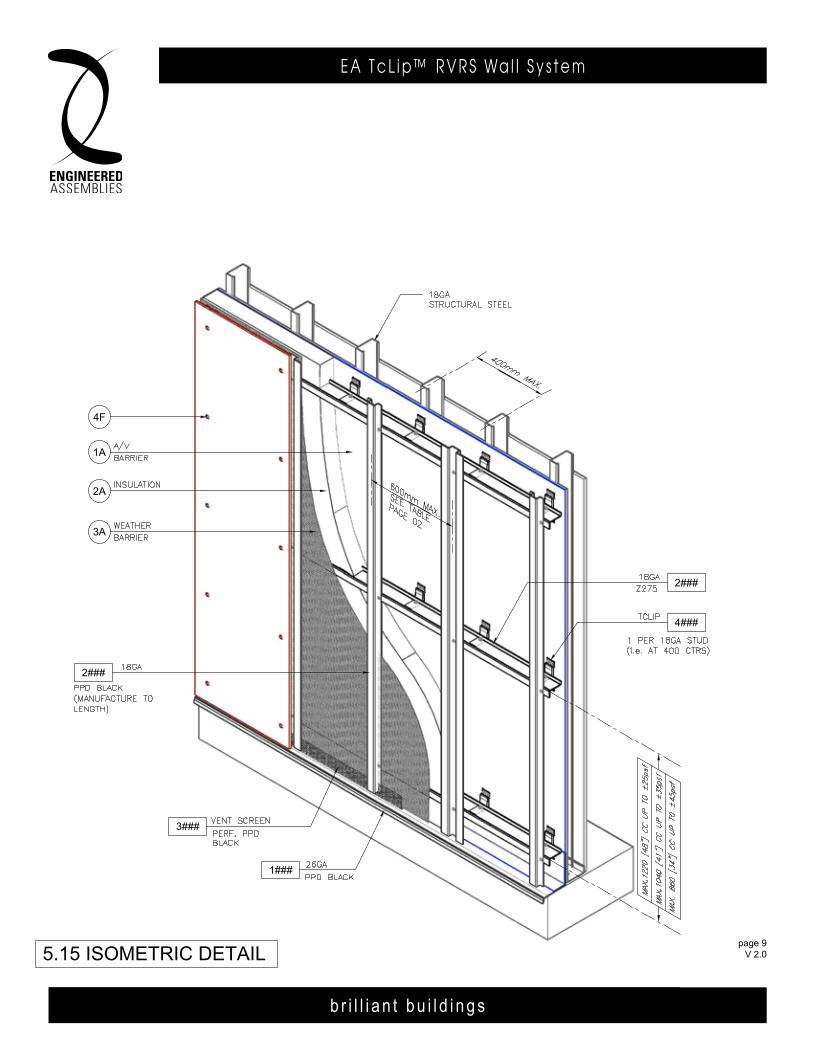
5.15 ISOMETRIC DETAIL
4F
2###
2A
3A
1A
2###
4###
1###
3###
page 903DEC13
page 9 FEB 2014
page 9 APR 2014
page 9 V 2.0

b r i l l i a n t b u i l d i n g s
E A T c L i p ™ R V R S Wa l l S y s t e m
page 10 V 2.0
b r i l l i a n t b u i l d i n g s
E A T c L i p R V R S Wa l l S y s t e m6535 M i l l c reek D r i ve , Un i t 75M iss i ssauga , On ta r i o , Canada L5N 2M2
T 905 .816 .2218F 905 .816 .9761
E i n fo@eng inee redassemb l i es .comW Eng inee redAssemb l i es .com
page 10 APR 2014
b r i l l i a n t b u i l d i n g s
E . A . I . T h E R m A L C L I p R . V. R . S . WA L L S y S T E m6535 M i l l c reek D r i ve , Un i t 75M iss i ssauga , On ta r i o , Canada L5N 2M2
T 905 .816 .2218F 905 .816 .9761
E i n fo@eng inee redassemb l i es .comW Eng inee redAssemb l i es .com
b r i l l i a n t b u i l d i n g s
E . A . I . T h E R m A L C L I p R . V. R . S . WA L L S y S T E m6535 M i l l c reek D r i ve , Un i t 75M iss i ssauga , On ta r i o , Canada L5N 2M2
T 905 .816 .2218F 905 .816 .9761
E i n fo@eng inee redassemb l i es .comW Eng inee redAssemb l i es .com
page 1003DEC13
b r i l l i a n t b u i l d i n g s
E . A . I . T h E R m A L C L I p R . V. R . S . WA L L S y S T E mEngineered Assembl ies Inc .6535 M i l l c reek D r i ve , Un i t 75M iss i ssauga , On ta r i o , Canada L5N 2M2
T 905 .816 .2218F 905 .816 .9761
E i n fo@eng inee redassemb l i es .comW Eng inee redAssemb l i es .com
page 818NOV13
b r i l l i a n t b u i l d i n g s
E . A . I . T h E R m A L C L I p R . V. R . S . WA L L S y S T E mEngineered Assembl ies Inc .6535 M i l l c reek D r i ve , Un i t 75M iss i ssauga , On ta r i o , Canada L5N 2M2
T 905 .816 .2218F 905 .816 .9761
E i n fo@eng inee redassemb l i es .comW Eng inee redAssemb l i es .com
page 2806OCT13
T100
ADjUsTMENT rANgE +5 -15
T100
page 10 FEB 2014
T100
page 10 APR 2014
T100
page 10 V 2.0

b r i l l i a n t b u i l d i n g s
E A T c L i p ™ R V R S Wa l l S y s t e m
page 11 V 2.0
b r i l l i a n t b u i l d i n g s
E A T c L i p R V R S Wa l l S y s t e m6535 M i l l c reek D r i ve , Un i t 75M iss i ssauga , On ta r i o , Canada L5N 2M2
T 905 .816 .2218F 905 .816 .9761
E i n fo@eng inee redassemb l i es .comW Eng inee redAssemb l i es .com
page 11 APR 2014
6535 M i l l c reek D r i ve , Un i t 75M iss i ssauga , On ta r i o , Canada L5N 2M2
T 905 .816 .2218F 905 .816 .9761
E i n fo@eng inee redassemb l i es .comW Eng inee redAssemb l i es .com
b r i l l i a n t b u i l d i n g s
E . A . I . T h E R m A L C L I p R . V. R . S . WA L L S y S T E m6535 M i l l c reek D r i ve , Un i t 75M iss i ssauga , On ta r i o , Canada L5N 2M2
T 905 .816 .2218F 905 .816 .9761
E i n fo@eng inee redassemb l i es .comW Eng inee redAssemb l i es .com
b r i l l i a n t b u i l d i n g s
E . A . I . T h E R m A L C L I p R . V. R . S . WA L L S y S T E m6535 M i l l c reek D r i ve , Un i t 75M iss i ssauga , On ta r i o , Canada L5N 2M2
T 905 .816 .2218F 905 .816 .9761
E i n fo@eng inee redassemb l i es .comW Eng inee redAssemb l i es .com
page 1103DEC13
b r i l l i a n t b u i l d i n g s
E . A . I . T h E R m A L C L I p R . V. R . S . WA L L S y S T E mEngineered Assembl ies Inc .6535 M i l l c reek D r i ve , Un i t 75M iss i ssauga , On ta r i o , Canada L5N 2M2
T 905 .816 .2218F 905 .816 .9761
E i n fo@eng inee redassemb l i es .comW Eng inee redAssemb l i es .com
page 918NOV13
b r i l l i a n t b u i l d i n g s
E . A . I . T h E R m A L C L I p R . V. R . S . WA L L S y S T E mEngineered Assembl ies Inc .6535 M i l l c reek D r i ve , Un i t 75M iss i ssauga , On ta r i o , Canada L5N 2M2
T 905 .816 .2218F 905 .816 .9761
E i n fo@eng inee redassemb l i es .comW Eng inee redAssemb l i es .com
page 2906OCT13
T125
ADjUsTMENT rANgE +5 -15
T125
page 11 FEB 2014
T125
page 11 APR 2014
T125
page 11 V 2.0
b r i l l i a n t b u i l d i n g s
E A T c L i p ™ R V R S Wa l l S y s t e m
page 12 V 2.0
b r i l l i a n t b u i l d i n g s
E A T c L i p R V R S Wa l l S y s t e m6535 M i l l c reek D r i ve , Un i t 75M iss i ssauga , On ta r i o , Canada L5N 2M2
T 905 .816 .2218F 905 .816 .9761
E i n fo@eng inee redassemb l i es .comW Eng inee redAssemb l i es .com
page 12 APR 2014
b r i l l i a n t b u i l d i n g s
E . A . I . T h E R m A L C L I p R . V. R . S . WA L L S y S T E m6535 M i l l c reek D r i ve , Un i t 75M iss i ssauga , On ta r i o , Canada L5N 2M2
T 905 .816 .2218F 905 .816 .9761
E i n fo@eng inee redassemb l i es .comW Eng inee redAssemb l i es .com
b r i l l i a n t b u i l d i n g s
E . A . I . T h E R m A L C L I p R . V. R . S . WA L L S y S T E m6535 M i l l c reek D r i ve , Un i t 75M iss i ssauga , On ta r i o , Canada L5N 2M2
T 905 .816 .2218F 905 .816 .9761
E i n fo@eng inee redassemb l i es .comW Eng inee redAssemb l i es .com
page 1203DEC13
b r i l l i a n t b u i l d i n g s
E . A . I . T h E R m A L C L I p R . V. R . S . WA L L S y S T E mEngineered Assembl ies Inc .6535 M i l l c reek D r i ve , Un i t 75M iss i ssauga , On ta r i o , Canada L5N 2M2
T 905 .816 .2218F 905 .816 .9761
E i n fo@eng inee redassemb l i es .comW Eng inee redAssemb l i es .com
page 1018NOV13
b r i l l i a n t b u i l d i n g s
E . A . I . T h E R m A L C L I p R . V. R . S . WA L L S y S T E mEngineered Assembl ies Inc .6535 M i l l c reek D r i ve , Un i t 75M iss i ssauga , On ta r i o , Canada L5N 2M2
T 905 .816 .2218F 905 .816 .9761
E i n fo@eng inee redassemb l i es .comW Eng inee redAssemb l i es .com
page 3006OCT13
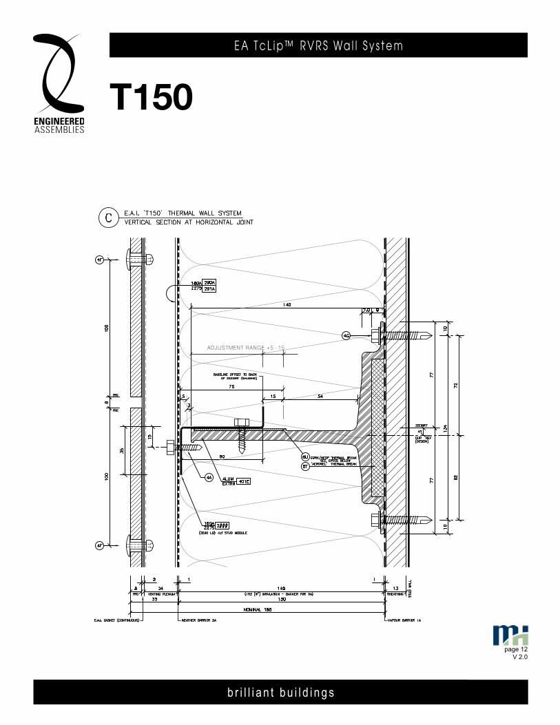
T150
ADjUsTMENT rANgE +5 -15
T150
page 12 FEB 2014
T150T150
b r i l l i a n t b u i l d i n g s
E A T c L i p ™ R V R S Wa l l S y s t e m
page 13 V 2.0
b r i l l i a n t b u i l d i n g s
E A T c L i p R V R S Wa l l S y s t e m6535 M i l l c reek D r i ve , Un i t 75M iss i ssauga , On ta r i o , Canada L5N 2M2
T 905 .816 .2218F 905 .816 .9761
E i n fo@eng inee redassemb l i es .comW Eng inee redAssemb l i es .com
page 13 APR 2014
6535 M i l l c reek D r i ve , Un i t 75M iss i ssauga , On ta r i o , Canada L5N 2M2
T 905 .816 .2218F 905 .816 .9761
E i n fo@eng inee redassemb l i es .comW Eng inee redAssemb l i es .com
b r i l l i a n t b u i l d i n g s
E . A . I . T h E R m A L C L I p R . V. R . S . WA L L S y S T E m6535 M i l l c reek D r i ve , Un i t 75M iss i ssauga , On ta r i o , Canada L5N 2M2
T 905 .816 .2218F 905 .816 .9761
E i n fo@eng inee redassemb l i es .comW Eng inee redAssemb l i es .com
b r i l l i a n t b u i l d i n g s
E . A . I . T h E R m A L C L I p R . V. R . S . WA L L S y S T E m6535 M i l l c reek D r i ve , Un i t 75M iss i ssauga , On ta r i o , Canada L5N 2M2
T 905 .816 .2218F 905 .816 .9761
E i n fo@eng inee redassemb l i es .comW Eng inee redAssemb l i es .com
page 1303DEC13
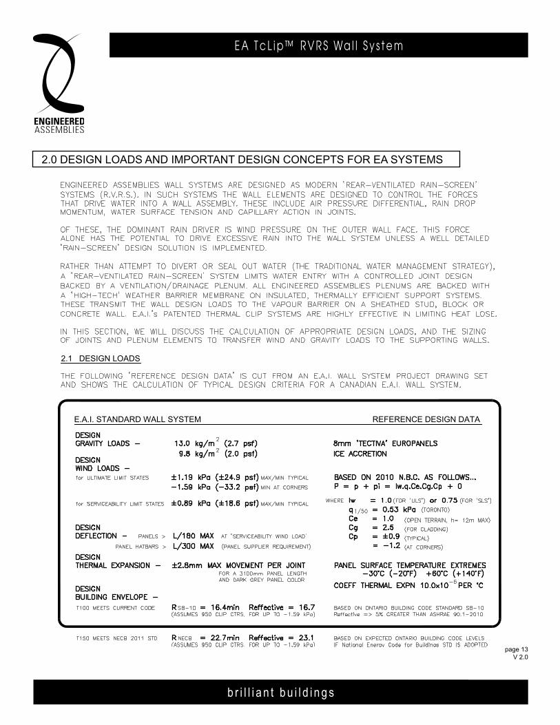
2.0 DESIGN LOADS AND IMPORTANT DESIGN CONCEPTS FOR E.A.I. SYSTEMS
REFERENCE DESIGN DATAE.A.I. STANDARD WALL SYSTEM
2.1 DESIGN LOADS
page 13 FEB 2014
2.0 deSign loadS and imPorTanT deSign ConCePTS For ea SySTemS
b r i l l i a n t b u i l d i n g s
E A T c L i p ™ R V R S Wa l l S y s t e m
page 14 V 2.0
b r i l l i a n t b u i l d i n g s
E A T c L i p R V R S Wa l l S y s t e m6535 M i l l c reek D r i ve , Un i t 75M iss i ssauga , On ta r i o , Canada L5N 2M2
T 905 .816 .2218F 905 .816 .9761
E i n fo@eng inee redassemb l i es .comW Eng inee redAssemb l i es .com
page 14 APR 2014
b r i l l i a n t b u i l d i n g s
E . A . I . T h E R m A L C L I p R . V. R . S . WA L L S y S T E m6535 M i l l c reek D r i ve , Un i t 75M iss i ssauga , On ta r i o , Canada L5N 2M2
T 905 .816 .2218F 905 .816 .9761
E i n fo@eng inee redassemb l i es .comW Eng inee redAssemb l i es .com
b r i l l i a n t b u i l d i n g s
E . A . I . T h E R m A L C L I p R . V. R . S . WA L L S y S T E m6535 M i l l c reek D r i ve , Un i t 75M iss i ssauga , On ta r i o , Canada L5N 2M2
T 905 .816 .2218F 905 .816 .9761
E i n fo@eng inee redassemb l i es .comW Eng inee redAssemb l i es .com
page 1403DEC13
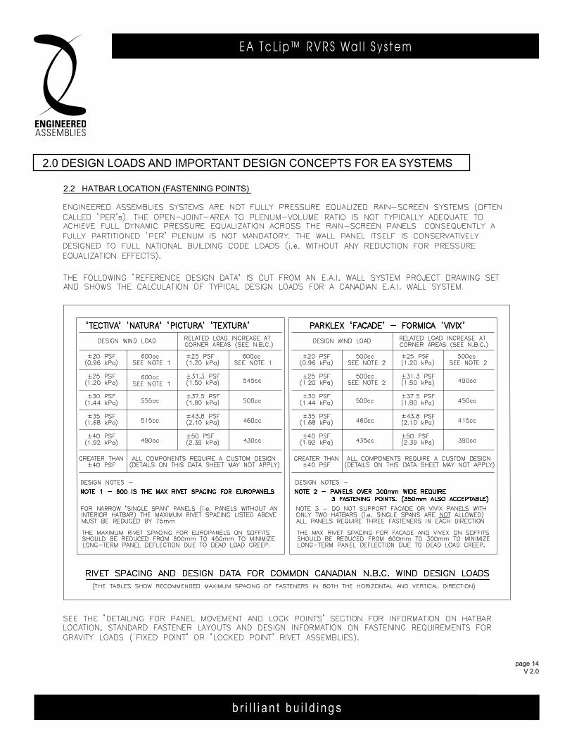
2.2 HATBAR LOCATION (FASTENING POINTS)
2.0 DESIGN LOADS AND IMPORTANT DESIGN CONCEPTS FOR E.A.I. SYSTEMS
page 14 FEB 2014
2.0 deSign loadS and imPorTanT deSign ConCePTS For ea SySTemS
b r i l l i a n t b u i l d i n g s
E A T c L i p ™ R V R S Wa l l S y s t e m
page 15 V 2.0
b r i l l i a n t b u i l d i n g s
E A T c L i p R V R S Wa l l S y s t e m6535 M i l l c reek D r i ve , Un i t 75M iss i ssauga , On ta r i o , Canada L5N 2M2
T 905 .816 .2218F 905 .816 .9761
E i n fo@eng inee redassemb l i es .comW Eng inee redAssemb l i es .com
page 15 APR 2014
6535 M i l l c reek D r i ve , Un i t 75M iss i ssauga , On ta r i o , Canada L5N 2M2
T 905 .816 .2218F 905 .816 .9761
E i n fo@eng inee redassemb l i es .comW Eng inee redAssemb l i es .com
b r i l l i a n t b u i l d i n g s
E . A . I . T h E R m A L C L I p R . V. R . S . WA L L S y S T E m6535 M i l l c reek D r i ve , Un i t 75M iss i ssauga , On ta r i o , Canada L5N 2M2
T 905 .816 .2218F 905 .816 .9761
E i n fo@eng inee redassemb l i es .comW Eng inee redAssemb l i es .com
b r i l l i a n t b u i l d i n g s
E . A . I . T h E R m A L C L I p R . V. R . S . WA L L S y S T E m6535 M i l l c reek D r i ve , Un i t 75M iss i ssauga , On ta r i o , Canada L5N 2M2
T 905 .816 .2218F 905 .816 .9761
E i n fo@eng inee redassemb l i es .comW Eng inee redAssemb l i es .com
page 1503DEC13
2.3 RAIN-SCREEN DESIGN FOR PLENUM INTEGRITY, DRAINAGE AND VENTING
2.3.1 PANEL JOINT SIZE AND BACKING
2.3.3 DRAINAGE AND VENTING
2.0 DESIGN LOADS AND IMPORTANT DESIGN CONCEPTS FOR E.A.I. SYSTEMS
2.3.2 PLENUM SIZE AND BACKING
page 15 FEB 2014
2.0 deSign loadS and imPorTanT deSign ConCePTS For ea SySTemS
b r i l l i a n t b u i l d i n g s
E A T c L i p ™ R V R S Wa l l S y s t e m
b r i l l i a n t b u i l d i n g s
E A T c L i p R V R S Wa l l S y s t e m ( T100 )E . A . I . T h E R m A L C L I p R . V. R . S . WA L L S y S T E m
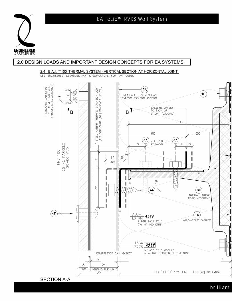
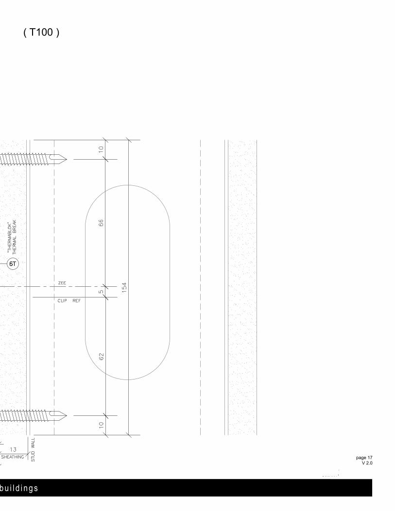
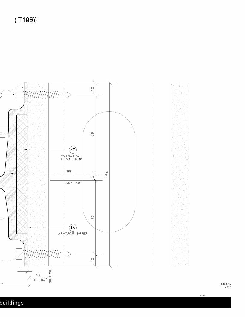
2.4 E.A.I. `T100' THERMAL SYSTEM - vERTICAL SECTION AT HORIZONTAL JOINT
B B
SECTION A-A
2.0 DESIgN LOADS AND IMPORTANT DESIgN CONCEPTS FOR E.A.I. SYSTEMS
( T100 )( T100 )
b r i l l i a n t b u i l d i n g s
2.0 deSign loadS and imPorTanT deSign ConCePTS For ea SySTemS
b r i l l i a n t b u i l d i n g s
page 17 V 2.0
( T100 )
b r i l l i a n t b u i l d i n g s
6535 M i l l c reek D r i ve , Un i t 75M iss i ssauga , On ta r i o , Canada L5N 2M2
T 905 .816 .2218F 905 .816 .9761
E i n fo@eng inee redassemb l i es .comW Eng inee redAssemb l i es .com
page 17 APR 2014
2.4 E.A.I. `T100' THERMAL SYSTEM - vERTICAL SECTION AT HORIZONTAL JOINT
B B
SECTION A-A
2.0 DESIgN LOADS AND IMPORTANT DESIgN CONCEPTS FOR E.A.I. SYSTEMS
( T100 )
b r i l l i a n t b u i l d i n g s
6535 M i l l c reek D r i ve , Un i t 75M iss i ssauga , On ta r i o , Canada L5N 2M2
T 905 .816 .2218F 905 .816 .9761
E i n fo@eng inee redassemb l i es .comW Eng inee redAssemb l i es .com
page 17 FEB 2014
b r i l l i a n t b u i l d i n g s
E A T c L i p ™ R V R S Wa l l S y s t e m
b r i l l i a n t b u i l d i n g s
E A T c L i p R V R S Wa l l S y s t e m ( T125)E . A . I . T h E R m A L C L I p R . V. R . S . WA L L S y S T E m
B B
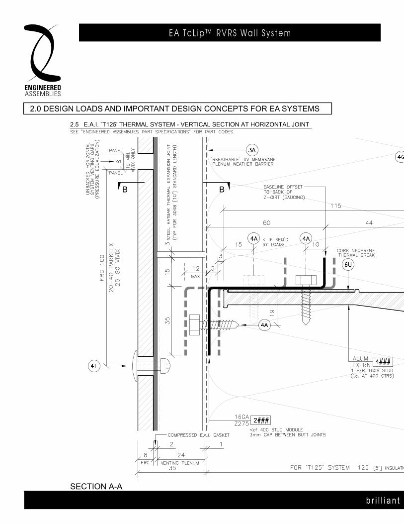
2.5 E.A.I. `T125' THERMAL SYSTEM - vERTICAL SECTION AT HORIZONTAL JOINT
2.0 DESIgN LOADS AND IMPORTANT DESIgN CONCEPTS FOR E.A.I. SYSTEMS
SECTION A-A
( T125 )( T125 )
b r i l l i a n t b u i l d i n g s
2.0 deSign loadS and imPorTanT deSign ConCePTS For ea SySTemS
b r i l l i a n t b u i l d i n g s
page 19 V 2.0
( T100 )( T125)
b r i l l i a n t b u i l d i n g s
6535 M i l l c reek D r i ve , Un i t 75M iss i ssauga , On ta r i o , Canada L5N 2M2
T 905 .816 .2218F 905 .816 .9761
E i n fo@eng inee redassemb l i es .comW Eng inee redAssemb l i es .com
page 19 APR 2014
B B
2.5 E.A.I. `T125' THERMAL SYSTEM - vERTICAL SECTION AT HORIZONTAL JOINT
2.0 DESIgN LOADS AND IMPORTANT DESIgN CONCEPTS FOR E.A.I. SYSTEMS
SECTION A-A
( T125 )6535 M i l l c reek D r i ve , Un i t 75M iss i ssauga , On ta r i o , Canada L5N 2M2
T 905 .816 .2218F 905 .816 .9761
E i n fo@eng inee redassemb l i es .comW Eng inee redAssemb l i es .com
b r i l l i a n t b u i l d i n g s
page 19 FEB 2014

b r i l l i a n t b u i l d i n g s
E A T c L i p ™ R V R S Wa l l S y s t e m
b r i l l i a n t b u i l d i n g s
E A T c L i p R V R S Wa l l S y s t e m ( T150 )E . A . I . T h E R m A L C L I p R . V. R . S . WA L L S y S T E m
B B
SECTION A-A
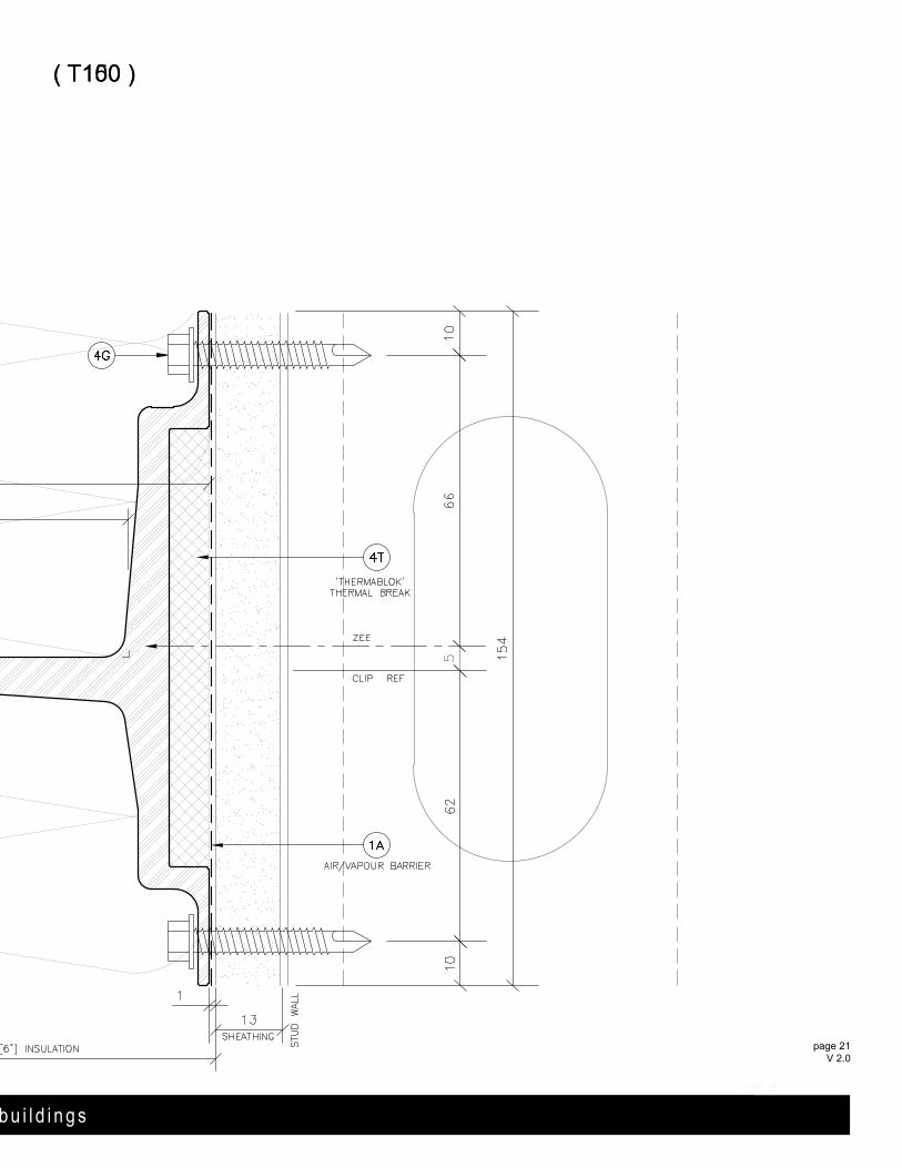
2.6 E.A.I. `T150' THERMAL SYSTEM - vERTICAL SECTION AT HORIZONTAL JOINT
2.0 DESIgN LOADS AND IMPORTANT DESIgN CONCEPTS FOR E.A.I. SYSTEMS
( T150 )( T150 )
b r i l l i a n t b u i l d i n g s
2.0 deSign loadS and imPorTanT deSign ConCePTS For ea SySTemS
b r i l l i a n t b u i l d i n g s
page 21 V 2.0
( T100 )( T150 )
b r i l l i a n t b u i l d i n g s
6535 M i l l c reek D r i ve , Un i t 75M iss i ssauga , On ta r i o , Canada L5N 2M2
T 905 .816 .2218F 905 .816 .9761
E i n fo@eng inee redassemb l i es .comW Eng inee redAssemb l i es .com
page 21 APR 2014
B B
SECTION A-A
2.6 E.A.I. `T150' THERMAL SYSTEM - vERTICAL SECTION AT HORIZONTAL JOINT
2.0 DESIgN LOADS AND IMPORTANT DESIgN CONCEPTS FOR E.A.I. SYSTEMS
( T150 )6535 M i l l c reek D r i ve , Un i t 75M iss i ssauga , On ta r i o , Canada L5N 2M2
T 905 .816 .2218F 905 .816 .9761
E i n fo@eng inee redassemb l i es .comW Eng inee redAssemb l i es .com
b r i l l i a n t b u i l d i n g s
page 21 FEB 2014
b r i l l i a n t b u i l d i n g s
E A T c L i p ™ R V R S Wa l l S y s t e m
page 22 V 2.0
b r i l l i a n t b u i l d i n g s
E A T c L i p R V R S Wa l l S y s t e m6535 M i l l c reek D r i ve , Un i t 75M iss i ssauga , On ta r i o , Canada L5N 2M2
T 905 .816 .2218F 905 .816 .9761
E i n fo@eng inee redassemb l i es .comW Eng inee redAssemb l i es .com
page 22 APR 2014
b r i l l i a n t b u i l d i n g s
E . A . I . T h E R m A L C L I p R . V. R . S . WA L L S y S T E m6535 M i l l c reek D r i ve , Un i t 75M iss i ssauga , On ta r i o , Canada L5N 2M2
T 905 .816 .2218F 905 .816 .9761
E i n fo@eng inee redassemb l i es .comW Eng inee redAssemb l i es .com
AA
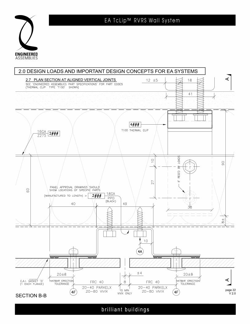
SECTION B-B
2.7 PLAN SECTION AT ALIgNED vERTICAL JOINTS
2.0 DESIgN LOADS AND IMPORTANT DESIgN CONCEPTS FOR E.A.I. SYSTEMS
page 22 FEB 2014
page 22 APR 2014
page 22 V 2.0
2.0 deSign loadS and imPorTanT deSign ConCePTS For ea SySTemS

b r i l l i a n t b u i l d i n g s
E A T c L i p ™ R V R S Wa l l S y s t e m
page 23 V 2.0
b r i l l i a n t b u i l d i n g s
E A T c L i p R V R S Wa l l S y s t e m6535 M i l l c reek D r i ve , Un i t 75M iss i ssauga , On ta r i o , Canada L5N 2M2
T 905 .816 .2218F 905 .816 .9761
E i n fo@eng inee redassemb l i es .comW Eng inee redAssemb l i es .com
page 23 APR 2014
6535 M i l l c reek D r i ve , Un i t 75M iss i ssauga , On ta r i o , Canada L5N 2M2
T 905 .816 .2218F 905 .816 .9761
E i n fo@eng inee redassemb l i es .comW Eng inee redAssemb l i es .com
b r i l l i a n t b u i l d i n g s
E . A . I . T h E R m A L C L I p R . V. R . S . WA L L S y S T E m6535 M i l l c reek D r i ve , Un i t 75M iss i ssauga , On ta r i o , Canada L5N 2M2
T 905 .816 .2218F 905 .816 .9761
E i n fo@eng inee redassemb l i es .comW Eng inee redAssemb l i es .com
AA
SECTION B-B
BB
2.8 PLAN SECTION AT STAGGERED VERTICAL JOINTS
2.0 DESIGN LOADS AND IMPORTANT DESIGN CONCEPTS FOR E.A.I. SYSTEMS
page 23 FEB 2014
page 23 FEB 2014
page 23 APR 2014
page 23 V 2.0
2.0 deSign loadS and imPorTanT deSign ConCePTS For ea SySTemS
b r i l l i a n t b u i l d i n g s
E A T c L i p ™ R V R S Wa l l S y s t e m
page 24 V 2.0
b r i l l i a n t b u i l d i n g s
E A T c L i p R V R S Wa l l S y s t e m6535 M i l l c reek D r i ve , Un i t 75M iss i ssauga , On ta r i o , Canada L5N 2M2
T 905 .816 .2218F 905 .816 .9761
E i n fo@eng inee redassemb l i es .comW Eng inee redAssemb l i es .com
page 24 APR 2014
b r i l l i a n t b u i l d i n g s
E . A . I . T H E R M A L C L I P R . V. R . S . WA L L S Y S T E M6535 M i l l c reek D r i ve , Un i t 75M iss i ssauga , On ta r i o , Canada L5N 2M2
T 905 .816 .2218F 905 .816 .9761
E i n fo@eng inee redassemb l i es .comW Eng inee redAssemb l i es .com
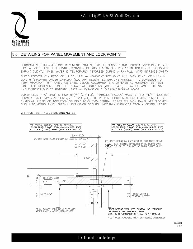
3.1 RIVET SETTING DETAIL AND NOTES
3.0 DETAILING FOR PANEL MOVEMENT AND LOCK POINTS
page 24 FEB 2014
b r i l l i a n t b u i l d i n g s
E A T c L i p ™ R V R S Wa l l S y s t e m
page 25 V 2.0
b r i l l i a n t b u i l d i n g s
E A T c L i p R V R S Wa l l S y s t e m6535 M i l l c reek D r i ve , Un i t 75M iss i ssauga , On ta r i o , Canada L5N 2M2
T 905 .816 .2218F 905 .816 .9761
E i n fo@eng inee redassemb l i es .comW Eng inee redAssemb l i es .com
page 25 APR 2014
6535 M i l l c reek D r i ve , Un i t 75M iss i ssauga , On ta r i o , Canada L5N 2M2
T 905 .816 .2218F 905 .816 .9761
E i n fo@eng inee redassemb l i es .comW Eng inee redAssemb l i es .com
b r i l l i a n t b u i l d i n g s
E . A . I . T h E R m A L C L I p R . V. R . S . WA L L S y S T E m6535 M i l l c reek D r i ve , Un i t 75M iss i ssauga , On ta r i o , Canada L5N 2M2
T 905 .816 .2218F 905 .816 .9761
E i n fo@eng inee redassemb l i es .comW Eng inee redAssemb l i es .com
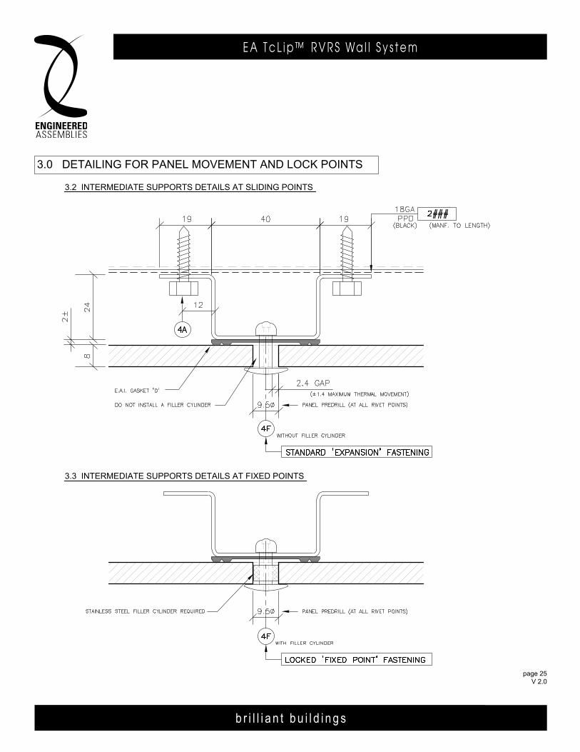
3.0 DETAILINg FOR PANEL MOvEMENT AND LOCK POINTS
3.2 INTERMEDIATE SuPPORTS DETAILS AT SLIDINg POINTS
3.3 INTERMEDIATE SuPPORTS DETAILS AT FIXED POINTS
page 25 FEB 2014
b r i l l i a n t b u i l d i n g s
E A T c L i p ™ R V R S Wa l l S y s t e m
page 26 V 2.0
b r i l l i a n t b u i l d i n g s
R . V. R . S S Y S T E M O N W O O D S U B S T R AT E6535 M i l l c reek D r i ve , Un i t 75M iss i ssauga , On ta r i o , Canada L5N 2M2
T 905 .816 .2218F 905 .816 .9761
E i n fo@eng inee redassemb l i es .comW Eng inee redAssemb l i es .com
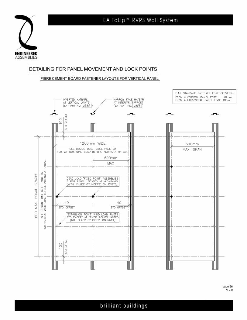
DETAILING FOR PANEL MOVEMENT AND LOCK POINTS
FIBER CEMENT BOARD FASTENER LAYOUTS FOR VERTICAL PANEL
page 0607Jun13
deTailing For Panel moVemenT and loCK PoinTS
Fibre

b r i l l i a n t b u i l d i n g s
E A T c L i p ™ R V R S Wa l l S y s t e m
page 27 V 2.0
b r i l l i a n t b u i l d i n g s
R . V. R . S S Y S T E M O N W O O D S U B S T R AT E6535 M i l l c reek D r i ve , Un i t 75M iss i ssauga , On ta r i o , Canada L5N 2M2
T 905 .816 .2218F 905 .816 .9761
E i n fo@eng inee redassemb l i es .comW Eng inee redAssemb l i es .com
DETAILING FOR PANEL MOVEMENT AND LOCK POINTS
FIBER CEMENT BOARD FASTENER LAYOUTS FOR HORIZONTAL PANEL
page 0707Jun13
deTailing For Panel moVemenT and loCK PoinTS
Fibre
b r i l l i a n t b u i l d i n g s
R . V. R . S S Y S T E M O N W O O D S U B S T R AT E6535 M i l l c reek D r i ve , Un i t 75M iss i ssauga , On ta r i o , Canada L5N 2M2
T 905 .816 .2218F 905 .816 .9761
E i n fo@eng inee redassemb l i es .comW Eng inee redAssemb l i es .com
DETAILING FOR PANEL MOVEMENT AND LOCK POINTS
FIBER CEMENT BOARD FASTENER LAYOUTS FOR VERTICAL PANEL
page 0607Jun13
b r i l l i a n t b u i l d i n g s
E A T c L i p ™ R V R S Wa l l S y s t e m
page 28 V 2.0
b r i l l i a n t b u i l d i n g s
E A T c L i p R V R S Wa l l S y s t e m6535 M i l l c reek D r i ve , Un i t 75M iss i ssauga , On ta r i o , Canada L5N 2M2
T 905 .816 .2218F 905 .816 .9761
E i n fo@eng inee redassemb l i es .comW Eng inee redAssemb l i es .com
page 28 APR 2014
b r i l l i a n t b u i l d i n g s
E . A . I . T h E R m A L C L I p R . V. R . S . WA L L S y S T E m6535 M i l l c reek D r i ve , Un i t 75M iss i ssauga , On ta r i o , Canada L5N 2M2
T 905 .816 .2218F 905 .816 .9761
E i n fo@eng inee redassemb l i es .comW Eng inee redAssemb l i es .com
b r i l l i a n t b u i l d i n g s
E . A . I . T h E R m A L C L I p R . V. R . S . WA L L S y S T E m6535 M i l l c reek D r i ve , Un i t 75M iss i ssauga , On ta r i o , Canada L5N 2M2
T 905 .816 .2218F 905 .816 .9761
E i n fo@eng inee redassemb l i es .comW Eng inee redAssemb l i es .com
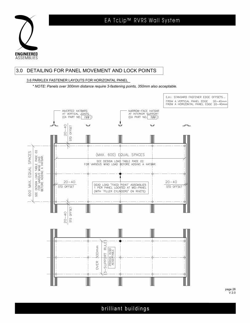
3.6 PARKLEX FASTENER LAYOUTS FOR VERTICAL PANEL
3.0 DETAILING FOR PANEL MOVEMENT AND LOCK POINTS
* NOTE: Panels over 300mm distance require 3-fastening points, 350mm also acceptable.
page 28 FEB 2014
page 28 FEB 2014
3.6 ParKlex FaSTener layouTS For HorizonTal Panel

b r i l l i a n t b u i l d i n g s
E A T c L i p ™ R V R S Wa l l S y s t e m
page 29 V 2.0
b r i l l i a n t b u i l d i n g s
E A T c L i p R V R S Wa l l S y s t e m6535 M i l l c reek D r i ve , Un i t 75M iss i ssauga , On ta r i o , Canada L5N 2M2
T 905 .816 .2218F 905 .816 .9761
E i n fo@eng inee redassemb l i es .comW Eng inee redAssemb l i es .com
page 29 APR 2014
6535 M i l l c reek D r i ve , Un i t 75M iss i ssauga , On ta r i o , Canada L5N 2M2
T 905 .816 .2218F 905 .816 .9761
E i n fo@eng inee redassemb l i es .comW Eng inee redAssemb l i es .com
b r i l l i a n t b u i l d i n g s
E . A . I . T h E R m A L C L I p R . V. R . S . WA L L S y S T E m6535 M i l l c reek D r i ve , Un i t 75M iss i ssauga , On ta r i o , Canada L5N 2M2
T 905 .816 .2218F 905 .816 .9761
E i n fo@eng inee redassemb l i es .comW Eng inee redAssemb l i es .com
3.7 PARKLEX BOARD FASTENER LAYOUTS FOR HORIZONTAL PANEL
3.0 DETAILING FOR PANEL MOVEMENT AND LOCK POINTS
* NOTE: Panels over 300mm distance require 3-fastening points, 350mm also acceptable.
page 29 FEB 2014
page 29 FEB 2014
3.7 ParKlex FaSTener layouTS For VerTiCal Panel

b r i l l i a n t b u i l d i n g s
E A T c L i p ™ R V R S Wa l l S y s t e m
page 30 V 2.0
b r i l l i a n t b u i l d i n g s
E A T c L i p R V R S Wa l l S y s t e m6535 M i l l c reek D r i ve , Un i t 75M iss i ssauga , On ta r i o , Canada L5N 2M2
T 905 .816 .2218F 905 .816 .9761
E i n fo@eng inee redassemb l i es .comW Eng inee redAssemb l i es .com
page 30 APR 2014
b r i l l i a n t b u i l d i n g s
E . A . I . T h E R m A L C L I p R . V. R . S . WA L L S y S T E m6535 M i l l c reek D r i ve , Un i t 75M iss i ssauga , On ta r i o , Canada L5N 2M2
T 905 .816 .2218F 905 .816 .9761
E i n fo@eng inee redassemb l i es .comW Eng inee redAssemb l i es .com
b r i l l i a n t b u i l d i n g s
E . A . I . T h E R m A L C L I p R . V. R . S . WA L L S y S T E m6535 M i l l c reek D r i ve , Un i t 75M iss i ssauga , On ta r i o , Canada L5N 2M2
T 905 .816 .2218F 905 .816 .9761
E i n fo@eng inee redassemb l i es .comW Eng inee redAssemb l i es .com
3.8 VIVIX BOARD FASTENER LAYOUTS FOR HORIZONTAL PANEL
3.0 DETAILING FOR PANEL MOVEMENT AND LOCK POINTS
page 30 FEB 2014
page 30 FEB 2014
b r i l l i a n t b u i l d i n g s
E A T c L i p ™ R V R S Wa l l S y s t e m
page 31 V 2.0
b r i l l i a n t b u i l d i n g s
E A T c L i p R V R S Wa l l S y s t e m6535 M i l l c reek D r i ve , Un i t 75M iss i ssauga , On ta r i o , Canada L5N 2M2
T 905 .816 .2218F 905 .816 .9761
E i n fo@eng inee redassemb l i es .comW Eng inee redAssemb l i es .com
page 31 APR 2014
6535 M i l l c reek D r i ve , Un i t 75M iss i ssauga , On ta r i o , Canada L5N 2M2
T 905 .816 .2218F 905 .816 .9761
E i n fo@eng inee redassemb l i es .comW Eng inee redAssemb l i es .com
b r i l l i a n t b u i l d i n g s
E . A . I . T h E R m A L C L I p R . V. R . S . WA L L S y S T E m6535 M i l l c reek D r i ve , Un i t 75M iss i ssauga , On ta r i o , Canada L5N 2M2
T 905 .816 .2218F 905 .816 .9761
E i n fo@eng inee redassemb l i es .comW Eng inee redAssemb l i es .com
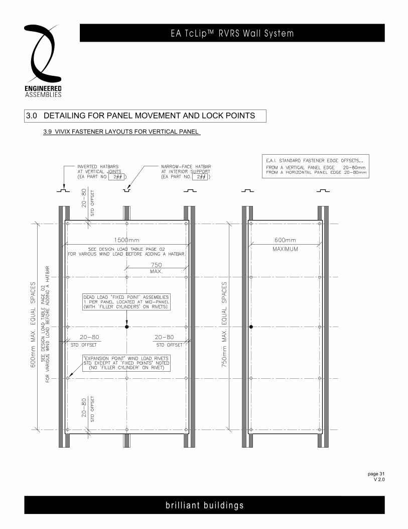
3.9 VIVIX FASTENER LAYOUTS FOR VERTICAL PANEL
3.0 DETAILING FOR PANEL MOVEMENT AND LOCK POINTS
page 31 FEB 2014
page 31 FEB 2014
b r i l l i a n t b u i l d i n g s
E A T c L i p ™ R V R S Wa l l S y s t e m
page 32 V 2.0
b r i l l i a n t b u i l d i n g s
E A T c L i p R V R S Wa l l S y s t e m6535 M i l l c reek D r i ve , Un i t 75M iss i ssauga , On ta r i o , Canada L5N 2M2
T 905 .816 .2218F 905 .816 .9761
E i n fo@eng inee redassemb l i es .comW Eng inee redAssemb l i es .com
page 32 APR 2014
b r i l l i a n t b u i l d i n g s
E . A . I . T h E R m A L C L I p R . V. R . S . WA L L S y S T E m6535 M i l l c reek D r i ve , Un i t 75M iss i ssauga , On ta r i o , Canada L5N 2M2
T 905 .816 .2218F 905 .816 .9761
E i n fo@eng inee redassemb l i es .comW Eng inee redAssemb l i es .com
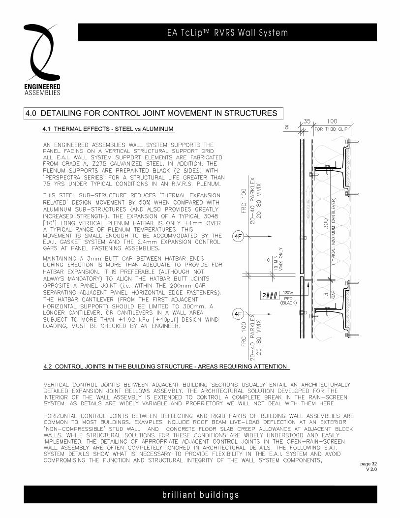
4.2 CONTROL JOINTS IN THE BuILDINg STRuCTuRE - AREAS REQuIRINg ATTENTION
4.1 THERMAL EFFECTS - STEEL vs ALuMINuM
4.0 DETAILINg FOR CONTROL JOINT MOvEMENT IN STRuCTuRES
page 32 FEB 2014
b r i l l i a n t b u i l d i n g s
E A T c L i p ™ R V R S Wa l l S y s t e m
page 33 V 2.0
b r i l l i a n t b u i l d i n g s
E A T c L i p R V R S Wa l l S y s t e m6535 M i l l c reek D r i ve , Un i t 75M iss i ssauga , On ta r i o , Canada L5N 2M2
T 905 .816 .2218F 905 .816 .9761
E i n fo@eng inee redassemb l i es .comW Eng inee redAssemb l i es .com
page 33 APR 2014
6535 M i l l c reek D r i ve , Un i t 75M iss i ssauga , On ta r i o , Canada L5N 2M2
T 905 .816 .2218F 905 .816 .9761
E i n fo@eng inee redassemb l i es .comW Eng inee redAssemb l i es .com
b r i l l i a n t b u i l d i n g s
E . A . I . T h E R m A L C L I p R . V. R . S . WA L L S y S T E m6535 M i l l c reek D r i ve , Un i t 75M iss i ssauga , On ta r i o , Canada L5N 2M2
T 905 .816 .2218F 905 .816 .9761
E i n fo@eng inee redassemb l i es .comW Eng inee redAssemb l i es .com
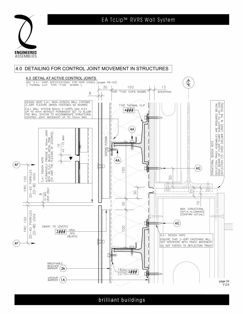
4.3 DETAIL AT ACTIvE CONTROL JOINTS
4.0 DETAILINg FOR CONTROL JOINT MOvEMENT IN STRuCTuRES
page 33 FEB 2014
b r i l l i a n t b u i l d i n g s
E A T c L i p ™ R V R S Wa l l S y s t e m
page 34 V 2.0
b r i l l i a n t b u i l d i n g s
E A T c L i p R V R S Wa l l S y s t e m6535 M i l l c reek D r i ve , Un i t 75M iss i ssauga , On ta r i o , Canada L5N 2M2
T 905 .816 .2218F 905 .816 .9761
E i n fo@eng inee redassemb l i es .comW Eng inee redAssemb l i es .com
page 34 APR 2014
b r i l l i a n t b u i l d i n g s
E . A . I . T h E R m A L C L I p R . V. R . S . WA L L S y S T E m6535 M i l l c reek D r i ve , Un i t 75M iss i ssauga , On ta r i o , Canada L5N 2M2
T 905 .816 .2218F 905 .816 .9761
E i n fo@eng inee redassemb l i es .comW Eng inee redAssemb l i es .com
b r i l l i a n t b u i l d i n g s
E . A . I . T h E R m A L C L I p R . V. R . S . WA L L S y S T E m6535 M i l l c reek D r i ve , Un i t 75M iss i ssauga , On ta r i o , Canada L5N 2M2
T 905 .816 .2218F 905 .816 .9761
E i n fo@eng inee redassemb l i es .comW Eng inee redAssemb l i es .com
page 3403DEC13
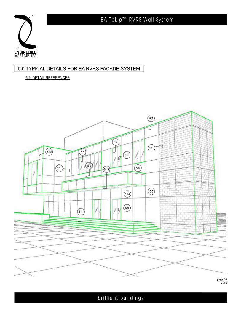
5.1 DETAIL REFERENCES
5.0 TYPICAL DETAILS FOR E.A.I. R.V.R.S. FACADE SYSTEM
page 34 FEB 2014
5.0 TyPiCal deTailS For ea rVrS FaCade SySTem
b r i l l i a n t b u i l d i n g s
E A T c L i p ™ R V R S Wa l l S y s t e m
page 35 V 2.0
b r i l l i a n t b u i l d i n g s
E A T c L i p R V R S Wa l l S y s t e m6535 M i l l c reek D r i ve , Un i t 75M iss i ssauga , On ta r i o , Canada L5N 2M2
T 905 .816 .2218F 905 .816 .9761
E i n fo@eng inee redassemb l i es .comW Eng inee redAssemb l i es .com
page 35 APR 2014
6535 M i l l c reek D r i ve , Un i t 75M iss i ssauga , On ta r i o , Canada L5N 2M2
T 905 .816 .2218F 905 .816 .9761
E i n fo@eng inee redassemb l i es .comW Eng inee redAssemb l i es .com
b r i l l i a n t b u i l d i n g s
E . A . I . T h E R m A L C L I p R . V. R . S . WA L L S y S T E m6535 M i l l c reek D r i ve , Un i t 75M iss i ssauga , On ta r i o , Canada L5N 2M2
T 905 .816 .2218F 905 .816 .9761
E i n fo@eng inee redassemb l i es .comW Eng inee redAssemb l i es .com
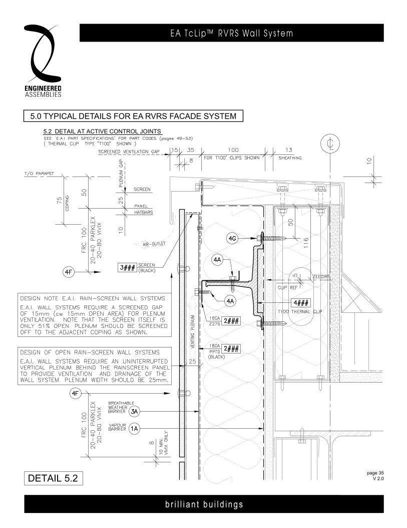
5.2 DETAIL AT ACTIvE CONTROL JOINTS
5.0 TYPICAL DETAILS FOR E.A.I. R.v.R.S. FACADE SYSTEM
DETAIL 5.2page 35
FEB 2014
5.0 TyPiCal deTailS For ea rVrS FaCade SySTem

b r i l l i a n t b u i l d i n g s
E A T c L i p ™ R V R S Wa l l S y s t e m
page 36 V 2.0
b r i l l i a n t b u i l d i n g s
E A T c L i p R V R S Wa l l S y s t e m6535 M i l l c reek D r i ve , Un i t 75M iss i ssauga , On ta r i o , Canada L5N 2M2
T 905 .816 .2218F 905 .816 .9761
E i n fo@eng inee redassemb l i es .comW Eng inee redAssemb l i es .com
page 36 APR 2014
b r i l l i a n t b u i l d i n g s
E . A . I . T h E R m A L C L I p R . V. R . S . WA L L S y S T E m6535 M i l l c reek D r i ve , Un i t 75M iss i ssauga , On ta r i o , Canada L5N 2M2
T 905 .816 .2218F 905 .816 .9761
E i n fo@eng inee redassemb l i es .comW Eng inee redAssemb l i es .com
5.3 vERTICAL SECTION AT CLOSED HORIZONTAL JOINT
5.0 TYPICAL DETAILS FOR E.A.I. R.v.R.S. FACADE SYSTEM
DETAIL 5.3page 36
FEB 2014
5.0 TyPiCal deTailS For ea rVrS FaCade SySTem
b r i l l i a n t b u i l d i n g s
E A T c L i p ™ R V R S Wa l l S y s t e m
page 37 V 2.0
b r i l l i a n t b u i l d i n g s
E A T c L i p R V R S Wa l l S y s t e m6535 M i l l c reek D r i ve , Un i t 75M iss i ssauga , On ta r i o , Canada L5N 2M2
T 905 .816 .2218F 905 .816 .9761
E i n fo@eng inee redassemb l i es .comW Eng inee redAssemb l i es .com
page 37 APR 2014
6535 M i l l c reek D r i ve , Un i t 75M iss i ssauga , On ta r i o , Canada L5N 2M2
T 905 .816 .2218F 905 .816 .9761
E i n fo@eng inee redassemb l i es .comW Eng inee redAssemb l i es .com
b r i l l i a n t b u i l d i n g s
E . A . I . T h E R m A L C L I p R . V. R . S . WA L L S y S T E m6535 M i l l c reek D r i ve , Un i t 75M iss i ssauga , On ta r i o , Canada L5N 2M2
T 905 .816 .2218F 905 .816 .9761
E i n fo@eng inee redassemb l i es .comW Eng inee redAssemb l i es .com
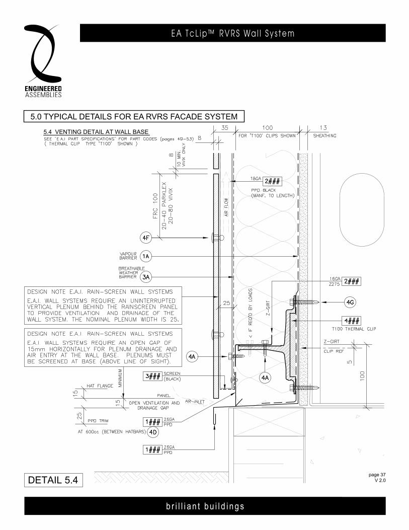
5.4 vENTINg DETAIL AT WALL BASE
5.0 TYPICAL DETAILS FOR E.A.I. R.v.R.S. FACADE SYSTEM
DETAIL 5.4page 37
FEB 2014
5.0 TyPiCal deTailS For ea rVrS FaCade SySTem
b r i l l i a n t b u i l d i n g s
E A T c L i p ™ R V R S Wa l l S y s t e m
page 38 V 2.0
b r i l l i a n t b u i l d i n g s
E A T c L i p R V R S Wa l l S y s t e m6535 M i l l c reek D r i ve , Un i t 75M iss i ssauga , On ta r i o , Canada L5N 2M2
T 905 .816 .2218F 905 .816 .9761
E i n fo@eng inee redassemb l i es .comW Eng inee redAssemb l i es .com
page 38 APR 2014
b r i l l i a n t b u i l d i n g s
E . A . I . T h E R m A L C L I p R . V. R . S . WA L L S y S T E m6535 M i l l c reek D r i ve , Un i t 75M iss i ssauga , On ta r i o , Canada L5N 2M2
T 905 .816 .2218F 905 .816 .9761
E i n fo@eng inee redassemb l i es .comW Eng inee redAssemb l i es .com
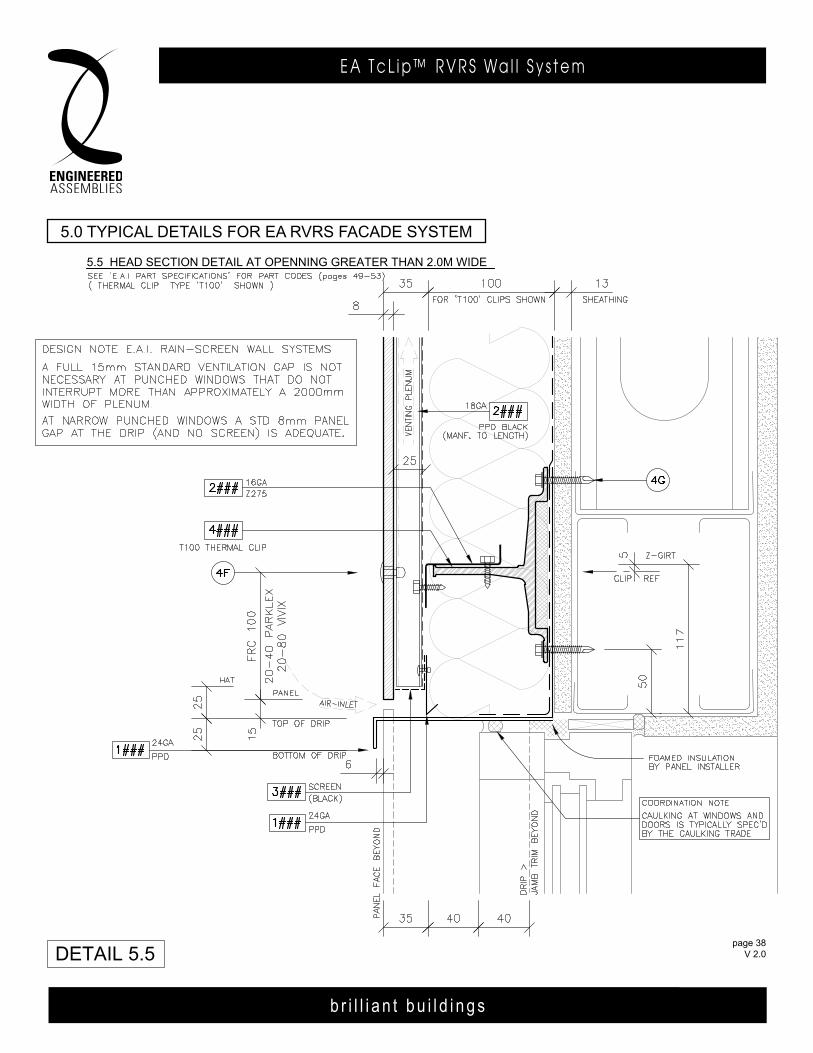
5.5 HEAD SECTION DETAIL AT OPENNINg gREATER THAN 2.0M WIDE
5.0 TYPICAL DETAILS FOR E.A.I. R.v.R.S. FACADE SYSTEM
DETAIL 5.5page 38
FEB 2014
5.0 TyPiCal deTailS For ea rVrS FaCade SySTem
b r i l l i a n t b u i l d i n g s
E A T c L i p ™ R V R S Wa l l S y s t e m
page 39 V 2.0
b r i l l i a n t b u i l d i n g s
E A T c L i p R V R S Wa l l S y s t e m6535 M i l l c reek D r i ve , Un i t 75M iss i ssauga , On ta r i o , Canada L5N 2M2
T 905 .816 .2218F 905 .816 .9761
E i n fo@eng inee redassemb l i es .comW Eng inee redAssemb l i es .com
page 39 APR 2014
6535 M i l l c reek D r i ve , Un i t 75M iss i ssauga , On ta r i o , Canada L5N 2M2
T 905 .816 .2218F 905 .816 .9761
E i n fo@eng inee redassemb l i es .comW Eng inee redAssemb l i es .com
b r i l l i a n t b u i l d i n g s
E . A . I . T h E R m A L C L I p R . V. R . S . WA L L S y S T E m6535 M i l l c reek D r i ve , Un i t 75M iss i ssauga , On ta r i o , Canada L5N 2M2
T 905 .816 .2218F 905 .816 .9761
E i n fo@eng inee redassemb l i es .comW Eng inee redAssemb l i es .com
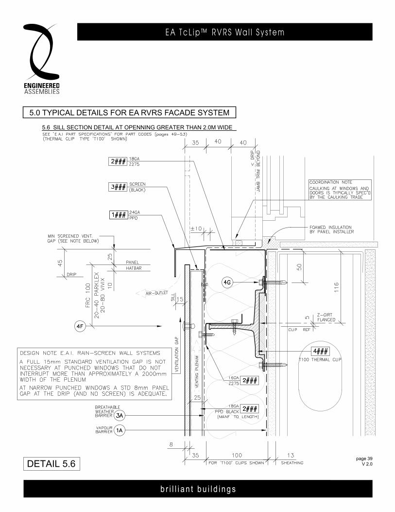
5.6 SILL SECTION DETAIL AT OPENNINg gREATER THAN 2.0M WIDE
5.0 TYPICAL DETAILS FOR E.A.I. R.v.R.S. FACADE SYSTEM
DETAIL 5.6page 39
FEB 2014
5.0 TyPiCal deTailS For ea rVrS FaCade SySTem

b r i l l i a n t b u i l d i n g s
E A T c L i p ™ R V R S Wa l l S y s t e m
page 40 V 2.0
b r i l l i a n t b u i l d i n g s
E A T c L i p R V R S Wa l l S y s t e m6535 M i l l c reek D r i ve , Un i t 75M iss i ssauga , On ta r i o , Canada L5N 2M2
T 905 .816 .2218F 905 .816 .9761
E i n fo@eng inee redassemb l i es .comW Eng inee redAssemb l i es .com
page 40 APR 2014
b r i l l i a n t b u i l d i n g s
E . A . I . T h E R m A L C L I p R . V. R . S . WA L L S y S T E m6535 M i l l c reek D r i ve , Un i t 75M iss i ssauga , On ta r i o , Canada L5N 2M2
T 905 .816 .2218F 905 .816 .9761
E i n fo@eng inee redassemb l i es .comW Eng inee redAssemb l i es .com
5.7 HEAD SECTION DETAIL AT OPENNINg LESS THAN 2.0M WIDE
5.0 TYPICAL DETAILS FOR E.A.I. R.v.R.S. FACADE SYSTEM
DETAIL 5.7page 40
FEB 2014
5.0 TyPiCal deTailS For ea rVrS FaCade SySTem
b r i l l i a n t b u i l d i n g s
E A T c L i p ™ R V R S Wa l l S y s t e m
page 41 V 2.0
b r i l l i a n t b u i l d i n g s
E A T c L i p R V R S Wa l l S y s t e m6535 M i l l c reek D r i ve , Un i t 75M iss i ssauga , On ta r i o , Canada L5N 2M2
T 905 .816 .2218F 905 .816 .9761
E i n fo@eng inee redassemb l i es .comW Eng inee redAssemb l i es .com
page 41 APR 2014
6535 M i l l c reek D r i ve , Un i t 75M iss i ssauga , On ta r i o , Canada L5N 2M2
T 905 .816 .2218F 905 .816 .9761
E i n fo@eng inee redassemb l i es .comW Eng inee redAssemb l i es .com
b r i l l i a n t b u i l d i n g s
E . A . I . T h E R m A L C L I p R . V. R . S . WA L L S y S T E m6535 M i l l c reek D r i ve , Un i t 75M iss i ssauga , On ta r i o , Canada L5N 2M2
T 905 .816 .2218F 905 .816 .9761
E i n fo@eng inee redassemb l i es .comW Eng inee redAssemb l i es .com
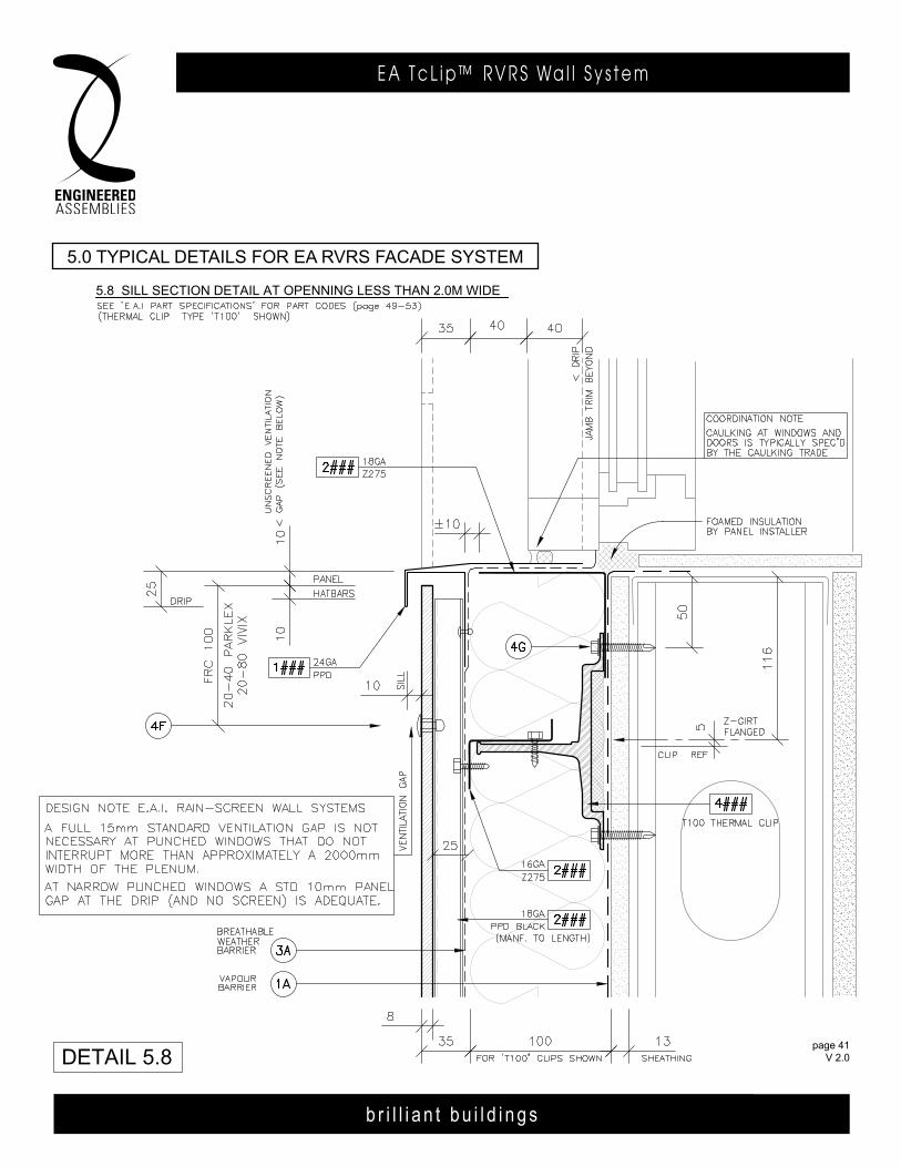
5.8 SILL SECTION DETAIL AT OPENNINg LESS THAN 2.0M WIDE
5.0 TYPICAL DETAILS FOR E.A.I. R.v.R.S. FACADE SYSTEM
DETAIL 5.8page 41
FEB 2014
5.0 TyPiCal deTailS For ea rVrS FaCade SySTem
b r i l l i a n t b u i l d i n g s
E A T c L i p ™ R V R S Wa l l S y s t e m
page 42 V 2.0
b r i l l i a n t b u i l d i n g s
E A T c L i p R V R S Wa l l S y s t e m6535 M i l l c reek D r i ve , Un i t 75M iss i ssauga , On ta r i o , Canada L5N 2M2
T 905 .816 .2218F 905 .816 .9761
E i n fo@eng inee redassemb l i es .comW Eng inee redAssemb l i es .com
page 42 APR 2014
b r i l l i a n t b u i l d i n g s
E . A . I . T h E R m A L C L I p R . V. R . S . WA L L S y S T E m6535 M i l l c reek D r i ve , Un i t 75M iss i ssauga , On ta r i o , Canada L5N 2M2
T 905 .816 .2218F 905 .816 .9761
E i n fo@eng inee redassemb l i es .comW Eng inee redAssemb l i es .com
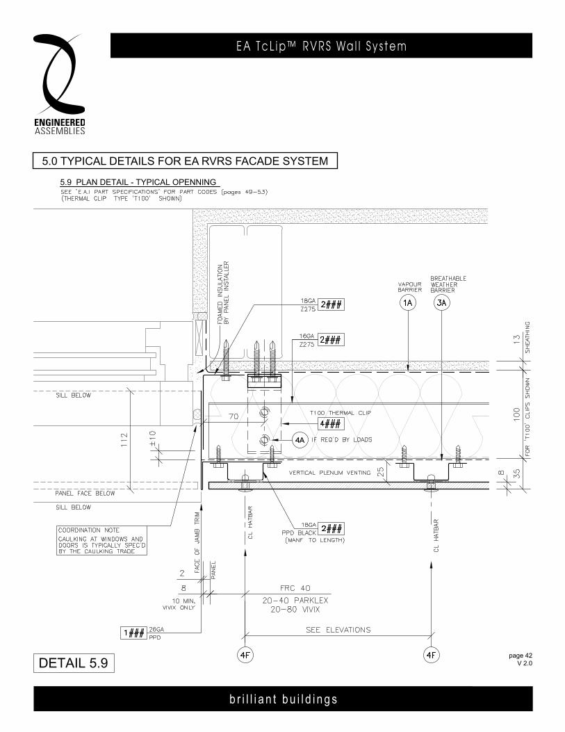
5.9 PLAN DETAIL - TYPICAL OPENNINg
5.0 TYPICAL DETAILS FOR E.A.I. R.v.R.S. FACADE SYSTEM
DETAIL 5.9page 42
FEB 2014
5.0 TyPiCal deTailS For ea rVrS FaCade SySTem
b r i l l i a n t b u i l d i n g s
E A T c L i p ™ R V R S Wa l l S y s t e m
page 43 V 2.0
b r i l l i a n t b u i l d i n g s
E A T c L i p R V R S Wa l l S y s t e m6535 M i l l c reek D r i ve , Un i t 75M iss i ssauga , On ta r i o , Canada L5N 2M2
T 905 .816 .2218F 905 .816 .9761
E i n fo@eng inee redassemb l i es .comW Eng inee redAssemb l i es .com
page 43 APR 2014
6535 M i l l c reek D r i ve , Un i t 75M iss i ssauga , On ta r i o , Canada L5N 2M2
T 905 .816 .2218F 905 .816 .9761
E i n fo@eng inee redassemb l i es .comW Eng inee redAssemb l i es .com
b r i l l i a n t b u i l d i n g s
E . A . I . T h E R m A L C L I p R . V. R . S . WA L L S y S T E m6535 M i l l c reek D r i ve , Un i t 75M iss i ssauga , On ta r i o , Canada L5N 2M2
T 905 .816 .2218F 905 .816 .9761
E i n fo@eng inee redassemb l i es .comW Eng inee redAssemb l i es .com
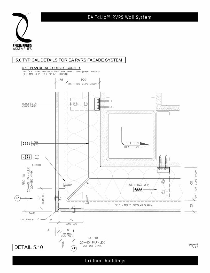
5.10 PLAN DETAIL - OuTSIDE CORNER
5.0 TYPICAL DETAILS FOR E.A.I. R.v.R.S. FACADE SYSTEM
DETAIL 5.10page 43
FEB 2014
5.0 TyPiCal deTailS For ea rVrS FaCade SySTem
b r i l l i a n t b u i l d i n g s
E A T c L i p ™ R V R S Wa l l S y s t e m
page 44 V 2.0
b r i l l i a n t b u i l d i n g s
E A T c L i p R V R S Wa l l S y s t e m6535 M i l l c reek D r i ve , Un i t 75M iss i ssauga , On ta r i o , Canada L5N 2M2
T 905 .816 .2218F 905 .816 .9761
E i n fo@eng inee redassemb l i es .comW Eng inee redAssemb l i es .com
page 44 APR 2014
b r i l l i a n t b u i l d i n g s
E . A . I . T h E R m A L C L I p R . V. R . S . WA L L S y S T E m6535 M i l l c reek D r i ve , Un i t 75M iss i ssauga , On ta r i o , Canada L5N 2M2
T 905 .816 .2218F 905 .816 .9761
E i n fo@eng inee redassemb l i es .comW Eng inee redAssemb l i es .com
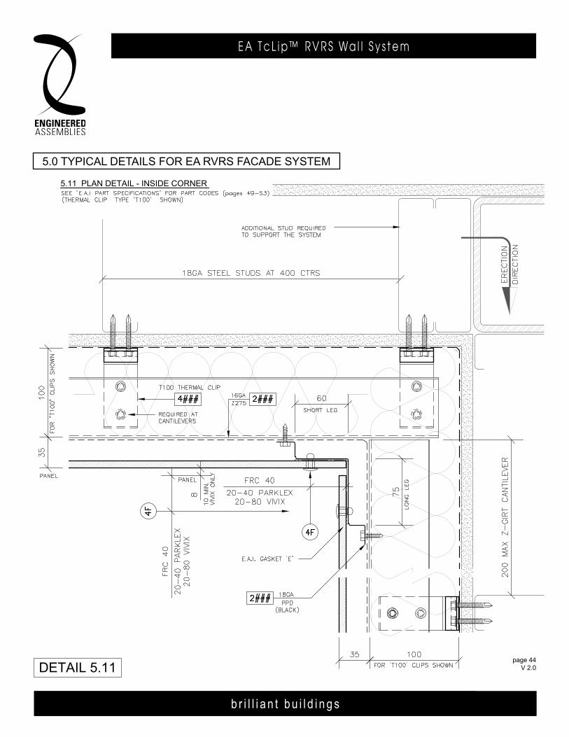
5.11 PLAN DETAIL - INSIDE CORNER
5.0 TYPICAL DETAILS FOR E.A.I. R.v.R.S. FACADE SYSTEM
DETAIL 5.11page 44
FEB 2014
5.0 TyPiCal deTailS For ea rVrS FaCade SySTem
b r i l l i a n t b u i l d i n g s
E A T c L i p ™ R V R S Wa l l S y s t e m
page 45 V 2.0
b r i l l i a n t b u i l d i n g s
E A T c L i p R V R S Wa l l S y s t e m6535 M i l l c reek D r i ve , Un i t 75M iss i ssauga , On ta r i o , Canada L5N 2M2
T 905 .816 .2218F 905 .816 .9761
E i n fo@eng inee redassemb l i es .comW Eng inee redAssemb l i es .com
page 45 APR 2014
6535 M i l l c reek D r i ve , Un i t 75M iss i ssauga , On ta r i o , Canada L5N 2M2
T 905 .816 .2218F 905 .816 .9761
E i n fo@eng inee redassemb l i es .comW Eng inee redAssemb l i es .com
b r i l l i a n t b u i l d i n g s
E . A . I . T h E R m A L C L I p R . V. R . S . WA L L S y S T E m6535 M i l l c reek D r i ve , Un i t 75M iss i ssauga , On ta r i o , Canada L5N 2M2
T 905 .816 .2218F 905 .816 .9761
E i n fo@eng inee redassemb l i es .comW Eng inee redAssemb l i es .com
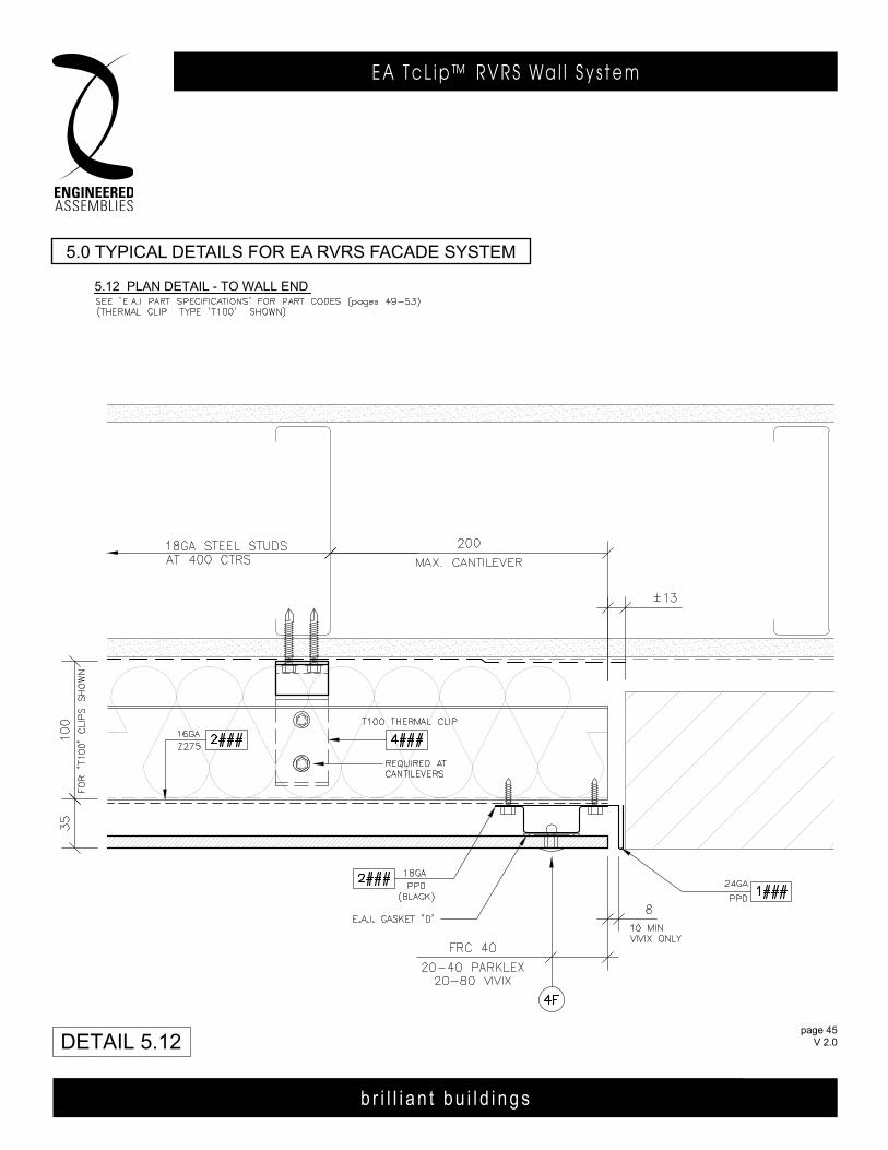
5.12 PLAN DETAIL - TO WALL END
5.0 TYPICAL DETAILS FOR E.A.I. R.v.R.S. FACADE SYSTEM
DETAIL 5.12page 45
FEB 2014
5.0 TyPiCal deTailS For ea rVrS FaCade SySTem
b r i l l i a n t b u i l d i n g s
E A T c L i p ™ R V R S Wa l l S y s t e m
page 46 V 2.0
b r i l l i a n t b u i l d i n g s
E A T c L i p R V R S Wa l l S y s t e m6535 M i l l c reek D r i ve , Un i t 75M iss i ssauga , On ta r i o , Canada L5N 2M2
T 905 .816 .2218F 905 .816 .9761
E i n fo@eng inee redassemb l i es .comW Eng inee redAssemb l i es .com
page 46 APR 2014
b r i l l i a n t b u i l d i n g s
E . A . I . T h E R m A L C L I p R . V. R . S . WA L L S y S T E m6535 M i l l c reek D r i ve , Un i t 75M iss i ssauga , On ta r i o , Canada L5N 2M2
T 905 .816 .2218F 905 .816 .9761
E i n fo@eng inee redassemb l i es .comW Eng inee redAssemb l i es .com
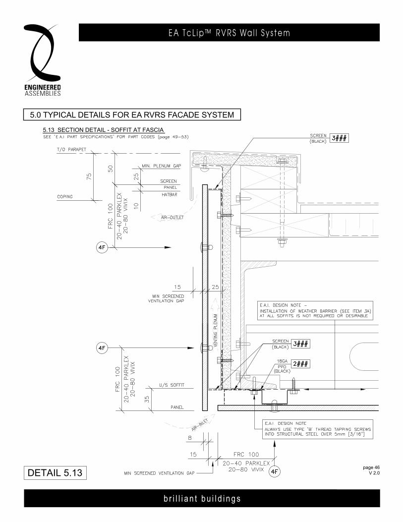
5.13 SECTION DETAIL - SOFFIT AT FASCIA
5.0 TYPICAL DETAILS FOR E.A.I. R.v.R.S. FACADE SYSTEM
DETAIL 5.13page 46
FEB 2014
5.0 TyPiCal deTailS For ea rVrS FaCade SySTem
b r i l l i a n t b u i l d i n g s
E A T c L i p ™ R V R S Wa l l S y s t e m
page 47 V 2.0
b r i l l i a n t b u i l d i n g s
E A T c L i p R V R S Wa l l S y s t e m6535 M i l l c reek D r i ve , Un i t 75M iss i ssauga , On ta r i o , Canada L5N 2M2
T 905 .816 .2218F 905 .816 .9761
E i n fo@eng inee redassemb l i es .comW Eng inee redAssemb l i es .com
page 47 APR 2014
6535 M i l l c reek D r i ve , Un i t 75M iss i ssauga , On ta r i o , Canada L5N 2M2
T 905 .816 .2218F 905 .816 .9761
E i n fo@eng inee redassemb l i es .comW Eng inee redAssemb l i es .com
b r i l l i a n t b u i l d i n g s
E . A . I . T h E R m A L C L I p R . V. R . S . WA L L S y S T E m6535 M i l l c reek D r i ve , Un i t 75M iss i ssauga , On ta r i o , Canada L5N 2M2
T 905 .816 .2218F 905 .816 .9761
E i n fo@eng inee redassemb l i es .comW Eng inee redAssemb l i es .com
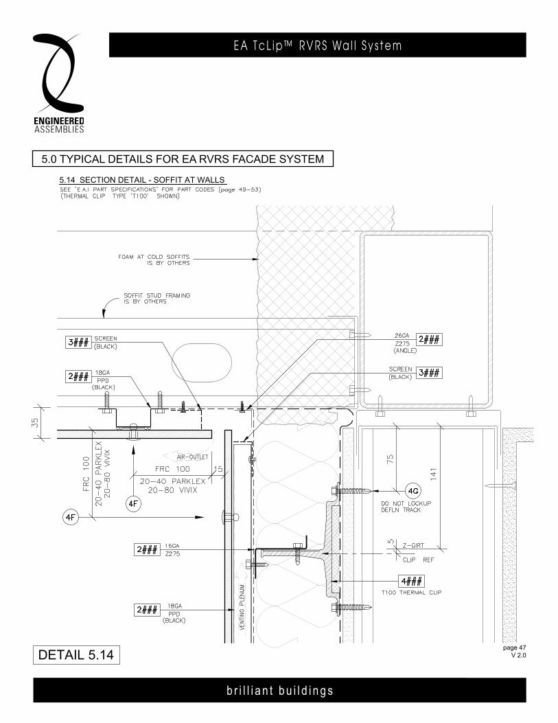
5.14 SECTION DETAIL - SOFFIT AT WALLS
5.0 TYPICAL DETAILS FOR E.A.I. R.v.R.S. FACADE SYSTEM
DETAIL 5.14page 47
FEB 2014
5.0 TyPiCal deTailS For ea rVrS FaCade SySTem

b r i l l i a n t b u i l d i n g s
E A T c L i p ™ R V R S Wa l l S y s t e m
page 48 V 2.0
b r i l l i a n t b u i l d i n g s
E A T c L i p R V R S Wa l l S y s t e m6535 M i l l c reek D r i ve , Un i t 75M iss i ssauga , On ta r i o , Canada L5N 2M2
T 905 .816 .2218F 905 .816 .9761
E i n fo@eng inee redassemb l i es .comW Eng inee redAssemb l i es .com
page 48 APR 2014
b r i l l i a n t b u i l d i n g s
E . A . I . T h E R m A L C L I p R . V. R . S . WA L L S y S T E m6535 M i l l c reek D r i ve , Un i t 75M iss i ssauga , On ta r i o , Canada L5N 2M2
T 905 .816 .2218F 905 .816 .9761
E i n fo@eng inee redassemb l i es .comW Eng inee redAssemb l i es .com
b r i l l i a n t b u i l d i n g s
E . A . I . T h E R m A L C L I p R . V. R . S . WA L L S y S T E m6535 M i l l c reek D r i ve , Un i t 75M iss i ssauga , On ta r i o , Canada L5N 2M2
T 905 .816 .2218F 905 .816 .9761
E i n fo@eng inee redassemb l i es .comW Eng inee redAssemb l i es .com
page 4803DEC13
5.15 ISOMETRIC DETAIL
4F
2###
2A
3A
1A
2###
4###
1###
3###
page 4803DEC13
page 48 FEB 2014
b r i l l i a n t b u i l d i n g s
E A T c L i p ™ R V R S Wa l l S y s t e m
page 49 V 2.0
b r i l l i a n t b u i l d i n g s
E A T c L i p R V R S Wa l l S y s t e m6535 M i l l c reek D r i ve , Un i t 75M iss i ssauga , On ta r i o , Canada L5N 2M2
T 905 .816 .2218F 905 .816 .9761
E i n fo@eng inee redassemb l i es .comW Eng inee redAssemb l i es .com
page 49 APR 2014
6535 M i l l c reek D r i ve , Un i t 75M iss i ssauga , On ta r i o , Canada L5N 2M2
T 905 .816 .2218F 905 .816 .9761
E i n fo@eng inee redassemb l i es .comW Eng inee redAssemb l i es .com
b r i l l i a n t b u i l d i n g s
E . A . I . T h E R m A L C L I p R . V. R . S . WA L L S y S T E m6535 M i l l c reek D r i ve , Un i t 75M iss i ssauga , On ta r i o , Canada L5N 2M2
T 905 .816 .2218F 905 .816 .9761
E i n fo@eng inee redassemb l i es .comW Eng inee redAssemb l i es .com
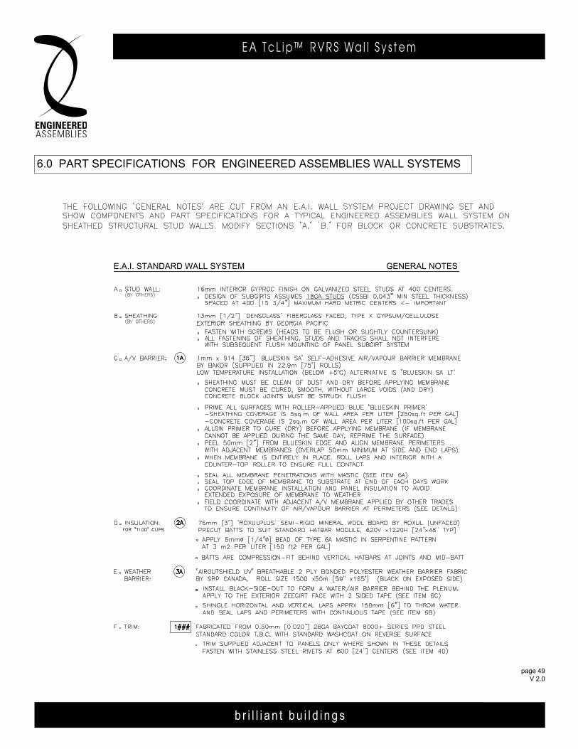
E.A.I. STANDARD WALL SYSTEM gENERAL NOTES
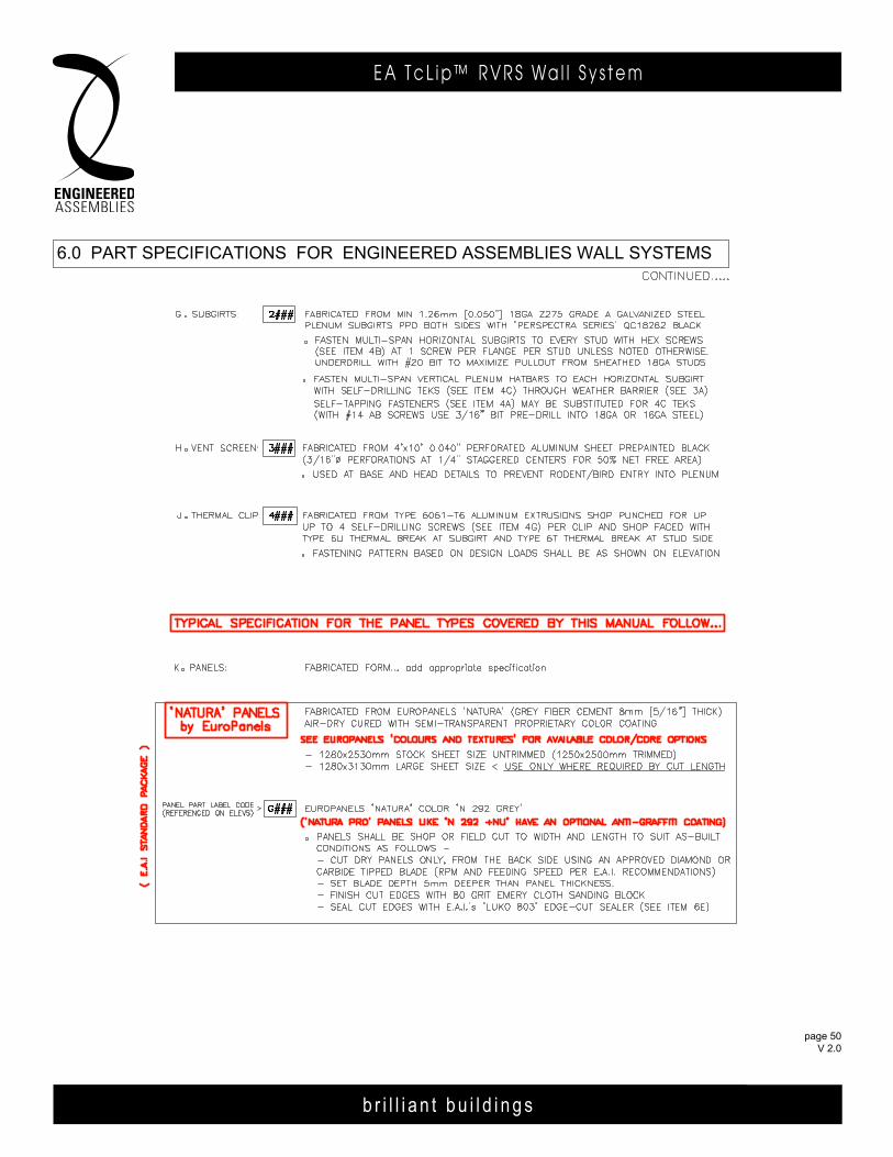
6.0 PART SPECIFICATIONS FOR ENgINEERED ASSEMBLIES WALL SYSTEMS
page 49 FEB 2014
b r i l l i a n t b u i l d i n g s
E A T c L i p ™ R V R S Wa l l S y s t e m
page 50 V 2.0
b r i l l i a n t b u i l d i n g s
E A T c L i p R V R S Wa l l S y s t e m6535 M i l l c reek D r i ve , Un i t 75M iss i ssauga , On ta r i o , Canada L5N 2M2
T 905 .816 .2218F 905 .816 .9761
E i n fo@eng inee redassemb l i es .comW Eng inee redAssemb l i es .com
page 50 APR 2014
b r i l l i a n t b u i l d i n g s
E . A . I . T h E R m A L C L I p R . V. R . S . WA L L S y S T E m6535 M i l l c reek D r i ve , Un i t 75M iss i ssauga , On ta r i o , Canada L5N 2M2
T 905 .816 .2218F 905 .816 .9761
E i n fo@eng inee redassemb l i es .comW Eng inee redAssemb l i es .com
6.0 PART SPECIFICATIONS FOR ENgINEERED ASSEMBLIES WALL SYSTEMS
page 50 FEB 2014

b r i l l i a n t b u i l d i n g s
E A T c L i p ™ R V R S Wa l l S y s t e m
page 51 V 2.0
b r i l l i a n t b u i l d i n g s
E A T c L i p R V R S Wa l l S y s t e m6535 M i l l c reek D r i ve , Un i t 75M iss i ssauga , On ta r i o , Canada L5N 2M2
T 905 .816 .2218F 905 .816 .9761
E i n fo@eng inee redassemb l i es .comW Eng inee redAssemb l i es .com
page 51 APR 2014
6535 M i l l c reek D r i ve , Un i t 75M iss i ssauga , On ta r i o , Canada L5N 2M2
T 905 .816 .2218F 905 .816 .9761
E i n fo@eng inee redassemb l i es .comW Eng inee redAssemb l i es .com
b r i l l i a n t b u i l d i n g s
E . A . I . T h E R m A L C L I p R . V. R . S . WA L L S y S T E m6535 M i l l c reek D r i ve , Un i t 75M iss i ssauga , On ta r i o , Canada L5N 2M2
T 905 .816 .2218F 905 .816 .9761
E i n fo@eng inee redassemb l i es .comW Eng inee redAssemb l i es .com
6.0 PART SPECIFICATIONS FOR ENgINEERED ASSEMBLIES WALL SYSTEMS
page 51 FEB 2014

b r i l l i a n t b u i l d i n g s
E A T c L i p ™ R V R S Wa l l S y s t e m
page 52 V 2.0
b r i l l i a n t b u i l d i n g s
E A T c L i p R V R S Wa l l S y s t e m6535 M i l l c reek D r i ve , Un i t 75M iss i ssauga , On ta r i o , Canada L5N 2M2
T 905 .816 .2218F 905 .816 .9761
E i n fo@eng inee redassemb l i es .comW Eng inee redAssemb l i es .com
page 52 APR 2014
b r i l l i a n t b u i l d i n g s
E . A . I . T h E R m A L C L I p R . V. R . S . WA L L S y S T E m6535 M i l l c reek D r i ve , Un i t 75M iss i ssauga , On ta r i o , Canada L5N 2M2
T 905 .816 .2218F 905 .816 .9761
E i n fo@eng inee redassemb l i es .comW Eng inee redAssemb l i es .com
6.0 PART SPECIFICATIONS FOR ENgINEERED ASSEMBLIES WALL SYSTEMS
page 52 FEB 2014
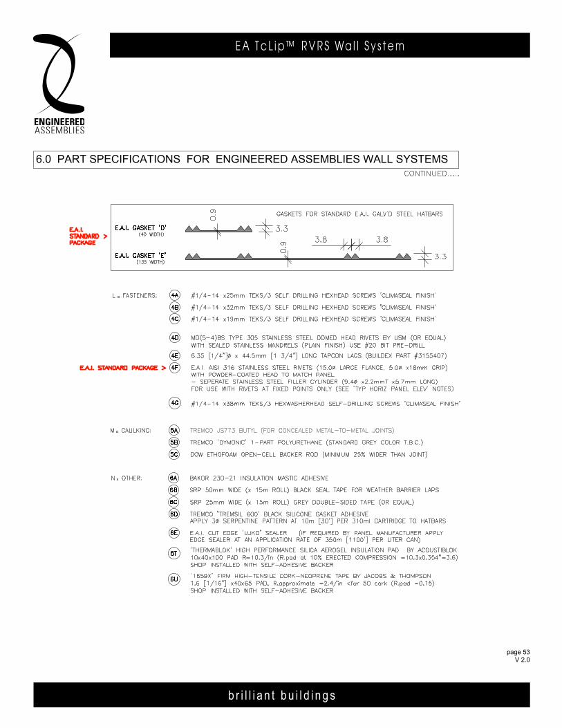
b r i l l i a n t b u i l d i n g s
E A T c L i p ™ R V R S Wa l l S y s t e m
page 53 V 2.0
b r i l l i a n t b u i l d i n g s
E A T c L i p R V R S Wa l l S y s t e m6535 M i l l c reek D r i ve , Un i t 75M iss i ssauga , On ta r i o , Canada L5N 2M2
T 905 .816 .2218F 905 .816 .9761
E i n fo@eng inee redassemb l i es .comW Eng inee redAssemb l i es .com
page 53 APR 2014
6535 M i l l c reek D r i ve , Un i t 75M iss i ssauga , On ta r i o , Canada L5N 2M2
T 905 .816 .2218F 905 .816 .9761
E i n fo@eng inee redassemb l i es .comW Eng inee redAssemb l i es .com
b r i l l i a n t b u i l d i n g s
E . A . I . T h E R m A L C L I p R . V. R . S . WA L L S y S T E m6535 M i l l c reek D r i ve , Un i t 75M iss i ssauga , On ta r i o , Canada L5N 2M2
T 905 .816 .2218F 905 .816 .9761
E i n fo@eng inee redassemb l i es .comW Eng inee redAssemb l i es .com
6.0 PART SPECIFICATIONS FOR ENgINEERED ASSEMBLIES WALL SYSTEMS
page 53 FEB 2014

b r i l l i a n t b u i l d i n g s
E A T c L i p ™ R V R S Wa l l S y s t e m
page 54 V 2.0
b r i l l i a n t b u i l d i n g s
E A T c L i p R V R S Wa l l S y s t e m6535 M i l l c reek D r i ve , Un i t 75M iss i ssauga , On ta r i o , Canada L5N 2M2
T 905 .816 .2218F 905 .816 .9761
E i n fo@eng inee redassemb l i es .comW Eng inee redAssemb l i es .com
page 54 APR 2014
b r i l l i a n t b u i l d i n g s
E . A . I . T h E R m A L C L I p R . V. R . S . WA L L S y S T E m6535 M i l l c reek D r i ve , Un i t 75M iss i ssauga , On ta r i o , Canada L5N 2M2
T 905 .816 .2218F 905 .816 .9761
E i n fo@eng inee redassemb l i es .comW Eng inee redAssemb l i es .com
b r i l l i a n t b u i l d i n g s
E . A . I . T h E R m A L C L I p R . V. R . S . WA L L S y S T E m6535 M i l l c reek D r i ve , Un i t 75M iss i ssauga , On ta r i o , Canada L5N 2M2
T 905 .816 .2218F 905 .816 .9761
E i n fo@eng inee redassemb l i es .comW Eng inee redAssemb l i es .com
page 5403DEC13
b r i l l i a n t b u i l d i n g s
E . A . I . T h E R m A L C L I p R . V. R . S . WA L L S y S T E m6535 M i l l c reek D r i ve , Un i t 75M iss i ssauga , On ta r i o , Canada L5N 2M2
T 905 .816 .2218F 905 .816 .9761
E i n fo@eng inee redassemb l i es .comW Eng inee redAssemb l i es .com
b r i l l i a n t b u i l d i n g s
E . A . I . T h E R m A L C L I p R . V. R . S . WA L L S y S T E m6535 M i l l c reek D r i ve , Un i t 75M iss i ssauga , On ta r i o , Canada L5N 2M2
T 905 .816 .2218F 905 .816 .9761
E i n fo@eng inee redassemb l i es .comW Eng inee redAssemb l i es .com
page 3620FEB13
page 3606MAY13page 5403DEC13
page 54 FEB 2014
7.0 IMPORTANT FIELD ERECTION NOTES
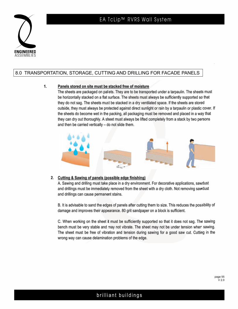
b r i l l i a n t b u i l d i n g s
E A T c L i p ™ R V R S Wa l l S y s t e m
page 55 V 2.0
b r i l l i a n t b u i l d i n g s
E A T c L i p R V R S Wa l l S y s t e m6535 M i l l c reek D r i ve , Un i t 75M iss i ssauga , On ta r i o , Canada L5N 2M2
T 905 .816 .2218F 905 .816 .9761
E i n fo@eng inee redassemb l i es .comW Eng inee redAssemb l i es .com
page 55 APR 2014
6535 M i l l c reek D r i ve , Un i t 75M iss i ssauga , On ta r i o , Canada L5N 2M2
T 905 .816 .2218F 905 .816 .9761
E i n fo@eng inee redassemb l i es .comW Eng inee redAssemb l i es .com
b r i l l i a n t b u i l d i n g s
E . A . I . T h E R m A L C L I p R . V. R . S . WA L L S y S T E m6535 M i l l c reek D r i ve , Un i t 75M iss i ssauga , On ta r i o , Canada L5N 2M2
T 905 .816 .2218F 905 .816 .9761
E i n fo@eng inee redassemb l i es .comW Eng inee redAssemb l i es .com
b r i l l i a n t b u i l d i n g s
E . A . I . T h E R m A L C L I p R . V. R . S . WA L L S y S T E m6535 M i l l c reek D r i ve , Un i t 75M iss i ssauga , On ta r i o , Canada L5N 2M2
T 905 .816 .2218F 905 .816 .9761
E i n fo@eng inee redassemb l i es .comW Eng inee redAssemb l i es .com
page 5503DEC13
b r i l l i a n t b u i l d i n g s
E . A . I . T h E R m A L C L I p R . V. R . S . WA L L S y S T E m6535 M i l l c reek D r i ve , Un i t 75M iss i ssauga , On ta r i o , Canada L5N 2M2
T 905 .816 .2218F 905 .816 .9761
E i n fo@eng inee redassemb l i es .comW Eng inee redAssemb l i es .com
b r i l l i a n t b u i l d i n g s
E . A . I . T h E R m A L C L I p R . V. R . S . WA L L S y S T E m6535 M i l l c reek D r i ve , Un i t 75M iss i ssauga , On ta r i o , Canada L5N 2M2
T 905 .816 .2218F 905 .816 .9761
E i n fo@eng inee redassemb l i es .comW Eng inee redAssemb l i es .com
page 3720FEB13
page 3706MAY13
page 55 FEB 2014
8.0 TRANSPORTATION, STORAgE, CuTTINg AND DRILLINg FOR FACADE PANELS
b r i l l i a n t b u i l d i n g s
E A T c L i p ™ R V R S Wa l l S y s t e m
page 56 V 2.0
b r i l l i a n t b u i l d i n g s
E A T c L i p R V R S Wa l l S y s t e m6535 M i l l c reek D r i ve , Un i t 75M iss i ssauga , On ta r i o , Canada L5N 2M2
T 905 .816 .2218F 905 .816 .9761
E i n fo@eng inee redassemb l i es .comW Eng inee redAssemb l i es .com
page 56 APR 2014
b r i l l i a n t b u i l d i n g s
E . A . I . T h E R m A L C L I p R . V. R . S . WA L L S y S T E m6535 M i l l c reek D r i ve , Un i t 75M iss i ssauga , On ta r i o , Canada L5N 2M2
T 905 .816 .2218F 905 .816 .9761
E i n fo@eng inee redassemb l i es .comW Eng inee redAssemb l i es .com
b r i l l i a n t b u i l d i n g s
E . A . I . T h E R m A L C L I p R . V. R . S . WA L L S y S T E m6535 M i l l c reek D r i ve , Un i t 75M iss i ssauga , On ta r i o , Canada L5N 2M2
T 905 .816 .2218F 905 .816 .9761
E i n fo@eng inee redassemb l i es .comW Eng inee redAssemb l i es .com
page 5603DEC13
b r i l l i a n t b u i l d i n g s
E . A . I . T h E R m A L C L I p R . V. R . S . WA L L S y S T E m6535 M i l l c reek D r i ve , Un i t 75M iss i ssauga , On ta r i o , Canada L5N 2M2
T 905 .816 .2218F 905 .816 .9761
E i n fo@eng inee redassemb l i es .comW Eng inee redAssemb l i es .com
b r i l l i a n t b u i l d i n g s
E . A . I . T h E R m A L C L I p R . V. R . S . WA L L S y S T E m6535 M i l l c reek D r i ve , Un i t 75M iss i ssauga , On ta r i o , Canada L5N 2M2
T 905 .816 .2218F 905 .816 .9761
E i n fo@eng inee redassemb l i es .comW Eng inee redAssemb l i es .com
page 3820FEB13
page 3806MAY13
page 56 FEB 2014
8.0 TRANSPORTATION, STORAgE, CuTTINg AND DRILLINg FOR FACADE PANELS
b r i l l i a n t b u i l d i n g s
E A T c L i p R V R S Wa l l S y s t e m6535 M i l l c reek D r i ve , Un i t 75M iss i ssauga , On ta r i o , Canada L5N 2M2
T 905 .816 .2218F 905 .816 .9761
E i n fo@eng inee redassemb l i es .comW Eng inee redAssemb l i es .com
page 55 APR 2014
6535 M i l l c reek D r i ve , Un i t 75M iss i ssauga , On ta r i o , Canada L5N 2M2
T 905 .816 .2218F 905 .816 .9761
E i n fo@eng inee redassemb l i es .comW Eng inee redAssemb l i es .com
b r i l l i a n t b u i l d i n g s
E . A . I . T h E R m A L C L I p R . V. R . S . WA L L S y S T E m6535 M i l l c reek D r i ve , Un i t 75M iss i ssauga , On ta r i o , Canada L5N 2M2
T 905 .816 .2218F 905 .816 .9761
E i n fo@eng inee redassemb l i es .comW Eng inee redAssemb l i es .com
b r i l l i a n t b u i l d i n g s
E . A . I . T h E R m A L C L I p R . V. R . S . WA L L S y S T E m6535 M i l l c reek D r i ve , Un i t 75M iss i ssauga , On ta r i o , Canada L5N 2M2
T 905 .816 .2218F 905 .816 .9761
E i n fo@eng inee redassemb l i es .comW Eng inee redAssemb l i es .com
page 5503DEC13
b r i l l i a n t b u i l d i n g s
E . A . I . T h E R m A L C L I p R . V. R . S . WA L L S y S T E m6535 M i l l c reek D r i ve , Un i t 75M iss i ssauga , On ta r i o , Canada L5N 2M2
T 905 .816 .2218F 905 .816 .9761
E i n fo@eng inee redassemb l i es .comW Eng inee redAssemb l i es .com
b r i l l i a n t b u i l d i n g s
E . A . I . T h E R m A L C L I p R . V. R . S . WA L L S y S T E m6535 M i l l c reek D r i ve , Un i t 75M iss i ssauga , On ta r i o , Canada L5N 2M2
T 905 .816 .2218F 905 .816 .9761
E i n fo@eng inee redassemb l i es .comW Eng inee redAssemb l i es .com
page 3720FEB13
page 3706MAY13
page 55 FEB 2014
8.0 TRANSPORTATION, STORAgE, CuTTINg AND DRILLINg FOR FACADE PANELS
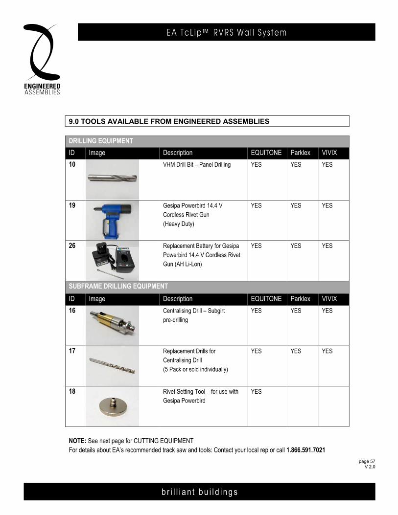
b r i l l i a n t b u i l d i n g s
E A T c L i p ™ R V R S Wa l l S y s t e m
page 57 V 2.0
Engineered Assemblies Inc.6535 Millcreek Drive, Unit 75Mississauga, Ontario, CanadaL5N 2M2
T 905.816.2218F 905.816.9761
E [email protected] EngineeredAssemblies.com
9.0 TOOLS AVAILABLE FROM ENGINEERED ASSEMBLIES
DRILLING EQUIPMENT
ID Image Description EQUITONE Parklex VIVIX
10 VHM Drill Bit – Panel Drilling YES YES YES
19 Gesipa Powerbird 14.4 V Cordless Rivet Gun (Heavy Duty)
YES YES YES
26 Replacement Battery for Gesipa Powerbird 14.4 V Cordless Rivet Gun (AH Li-Lon)
YES YES YES
SUBFRAME DRILLING EQUIPMENT
ID Image Description EQUITONE Parklex VIVIX
16 Centralising Drill – Subgirt pre-drilling
YES YES YES
17 Replacement Drills for Centralising Drill(5 Pack or sold individually)
YES YES YES
18 Rivet Setting Tool – for use with Gesipa Powerbird
YES
NOTE: See next page for CUTTING EQUIPMENTFor details about EA’s recommended track saw and tools: Contact your local rep or call 1.866.591.7021
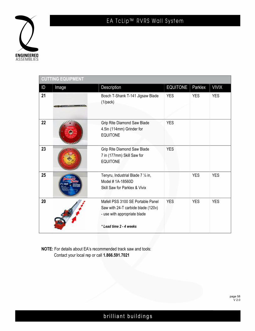
b r i l l i a n t b u i l d i n g s
E A T c L i p ™ R V R S Wa l l S y s t e m
page 58 V 2.0
August 5, 2015page 2 of 2
CUTTING EQUIPMENT
ID Image Description EQUITONE Parklex VIVIX
21 Bosch T-Shank T-141 Jigsaw Blade (1/pack)
YES YES YES
22 Grip Rite Diamond Saw Blade 4.5in (114mm) Grinder for EQUITONE
YES
23 Grip Rite Diamond Saw Blade 7 in (177mm) Skill Saw forEQUITONE
YES
25 Tenyru, Industrial Blade 7 ¼ in, Model # 1A-18560D Skill Saw for Parklex & Vivix
YES YES
20 Mafell PSS 3100 SE Portable Panel Saw with 24-T carbide blade (120v) - use with appropriate blade
* Lead time 2 - 4 weeks
YES YES YES
NOTE: For details about EA’s recommended track saw and tools: Contact your local rep or call 1.866.591.7021
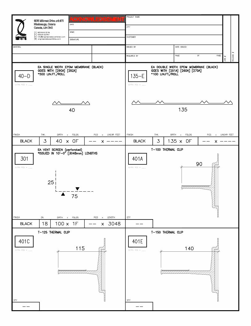
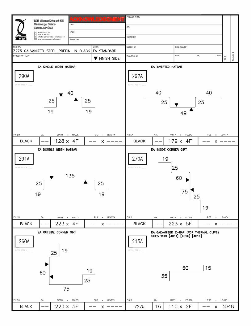


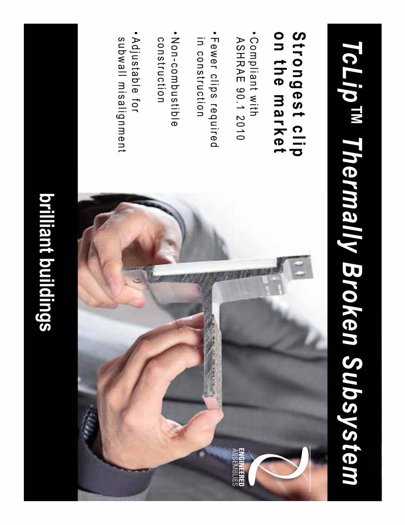
Stro
ng
es
t clip
on
the
ma
rke
t• C
om
plia
nt w
ith A
SH
RA
E 9
0.1
20
10
• Fe
we
r clips re
qu
ired
in co
nstru
ction
• No
n-co
mb
ustib
leco
nstru
ction
• Ad
justa
ble
for
sub
wa
ll misa
lign
me
nt
TcLip™ Therm
ally Broken S
ubsystem
brilliant buildings
b r i l l i a n t b u i l d i n g s
Engineered Assembl ies Inc .1.866 .591 .7021in fo@eng inee redassemb l i es .com
Version 2.0
TcLip™ Structural & Thermal Design Calculations


b r i l l i a n t b u i l d i n g s
page 3V 2 .0
T c L i p ™ R V R S WA L L S Y S T E M
b r i l l i a n t b u i l d i n g s
E . A . I . T h E r m A l C l I p r . V. r . S . WA l l S y S T E mEngineered Assembl ies Inc .6535 M i l l c reek D r i ve , Un i t 75M iss i ssauga , On ta r i o , Canada L5N 2M2
T 905 .816 .2218F 905 .816 .9761
E i n fo@eng inee redassemb l i es .comW Eng inee redAssemb l i es .com
page 203DEC13
Table of ContentsEng inee red Assemb l i es I n t roduc t ion 3Eng inee red Assemb l i es Execu t i ve Summary 4Quick ReferencesEf fec t i ve R Va lue Se lec t ion Gu ide Char t 6I somet r i c De ta i l 7T100 The rma l Wa l l Sys tem Deta i l s 8T125 The rma l Wa l l Sys tem Deta i l s 9T150 The rma l Wa l l Sys tem Deta i l s 10
Read Jones Chr is toffersen St ructura l Report I n t roduc t ion 12Worked Examp le ( f i gu re 01 ) 13Arch i tec tu ra l Des ign Char ts ( f i gu res 02-04 ) 14Eng inee r ing Des ign Char ts ( F igu res 05-07 ) 17Therma l Images Summary 20
Morr ison Hershf ie ld Thermal Report 1. I n t roduc t ion 222 . Mode l i ng P rocedures 223 . The rma l Ana l ys i s 223 .1 C lea r F i e ld The rma l Pe r fo rmance 233 .2 S lab Edge L inea r Transmi t tance 233 .3 Impac t o f Ba t t I nsu la t i on i n S tee l S tud Cav i t y 254 . Sens i t i v i t y Ana l ys i s 264 .1 Insu la t i on Type 264 .2 C l ip Spac ing 275 . Bu i ld ing Enve lope Requ i rements i n Canada 286 . Conc lus ion 32
Append ix A – C l ip Sys tem Deta i l s and Mate r i a l P roper t i es 33Append ix B – Ash rae 1365-RP Methodo logy 40Append ix C – E f f ec t i ve Assemb ly R-Va lues 47Append ix D – Examp le S imu la ted Tempera tu re D is t r ibu t ion 51
b r i l l i a n t b u i l d i n g s
page 4V 2 .0
T c L i p ™ R V R S WA L L S Y S T E M
We are pleased to provide you thermal and structural testing and analysis for TcLip™; Thermally Broken Subsystem for use with a variety of facades including: fibre cement, solid phenolic, ceramic, wood veneer, porcelain, etc.
INTRODUCTIONThis guide provides thermal and structural analysis of Engineered Assemblies’ TcLip™; Thermally Broken Subsystem. The TcLip™ system supports a variety of façade panels. The main purpose of this guide is to create a better understanding of the performance capabilities and benefits of TcLip™.
Refer to the “Quick References” section of this guide for a breakdown of performance details and system drawings. System drawings 1, 2 and 3 (pgs. 8-10) detail Engineered Assemblies Hidden Fastening system.
DISCLAIMERThe use of this information shows your acceptance of these terms. The information is intended to provide background information on Engineered Assemblies building envelope systems; specifically TcLip™; Thermally Broken Subsystem with reference to the Hidden Fastener System.
Although Engineered Assemblies Inc. makes reasonable efforts to present information which is up to date and accurate. Engineered Assemblies Inc. makes no representation or warranty as to the adequacy, accuracy completeness or correctness of such information, nor does it warrant or represent that the information provided is complete in every respect.
Engineered Assemblies Inc. shall not have liability resulting from the use of the information provided, the absence of any specific information, the possible interruptions or technical errors of this information and/or the content herein.
Your Engineered Assemblies Inc. Team
Engineered Assemblies Inc. 6535 Millcreek Drive, Unit 75 Mississauga, Ontario, Canada L5N 2M2 T 905.816.2218 F 905.816.9761 E [email protected] W EngineeredAssemblies.com
Experience Success through Partnership with our Services: • We collaborate on design; providing value engineering, mockups,
samples, lunch and learns, webinars, etc. • We provide extensively-detailed, stamped shop drawings. • We offer complete system supply. Engineered Assemblies understands and promotes the philosophy of partnership. We maintain a cooperative presence and focus on achieving the desired goal; completing a project on time and on budget to the highest of industry standards. We take a common-sense approach to systems development; offering functional assemblies that are cost effective without compromising the designer's intent. From detailing to field installation practicality, our 20 years of experience provide a keen eye on the design and strong handle on the limiting factors of the field. OUR SYSTEMS: • TcLip Thermally Broken Subsystem • Hidden Fastener System (HF) • Rear Ventilated Rain Screen Systems (RVRS) OUR PRODUCTS: • Equitone Fibre Cement façade • Parklex Natural Wood façade • Savoia Porcelain façade • Tonality Ceramic façade • VIVIX Solid Phenolic façade • Corten, Zinc, Copper, Stainless Steel & Aluminum façade • CPI Daylighting solutions • Imetco Metal roof and wall systems
Engineered Assemblies Unites the House of Design
to The Field of Construction
OUR PARTNERS
™
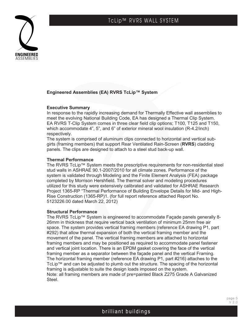
b r i l l i a n t b u i l d i n g s
page 5V 2 .0
T c L i p ™ R V R S WA L L S Y S T E M
b r i l l i a n t b u i l d i n g s
E . A . I . T h E r m A l C l I p r . V. r . S . WA l l S y S T E mEngineered Assembl ies Inc .6535 M i l l c reek D r i ve , Un i t 75M iss i ssauga , On ta r i o , Canada L5N 2M2
T 905 .816 .2218F 905 .816 .9761
E i n fo@eng inee redassemb l i es .comW Eng inee redAssemb l i es .com
page 403DEC13
Engineered Assemblies Inc.6535 Millcreek Drive, Unit 75Mississauga, Ontario, CanadaL5N 2M2
T 905.816.2218F 905.816.9761
E [email protected] EngineeredAssemblies.com
June 21, 2012
Engineered Assemblies (EA) RVRS TcLip™ System
Executive SummaryIn response to the rapidly increasing demand for Thermally Effective wall assemblies to meet the evolving National Building Code, EA has designed a Thermal Clip System. EA RVRS T-Clip System comes in three clear field clip options; T100, T125 and T150, which accommodate 4”, 5”, and 6” of exterior mineral wool insulation (R-4.2/inch) respectively. The system is comprised of aluminum clips connected to horizontal and vertical sub-girts (framing members) that support Rear Ventilated Rain-Screen (RVRS) cladding panels. The clips are designed to attach to a steel stud back-up wall.
Thermal Performance The RVRS TcLip™ System meets the prescriptive requirements for non-residential steel stud walls in ASHRAE 90.1-2007/2010 for all climate zones. Performance of the system is validated through Modeling and the Finite Element Analysis (FEA) package completed by Morrison Hershfield. The thermal solver and modeling procedures utilized for this study were extensively calibrated and validated for ASHRAE Research Project 1365-RP “Thermal Performance of Building Envelope Details for Mid- and High-Rise Construction (1365-RP)1. (for full report reference attached Report No. 5123226.00 dated March 22, 2012)
Structural PerformanceThe RVRS TcLip™ System is engineered to accommodate Façade panels generally 8-26mm in thickness that require vertical back ventilation of minimum 25mm free air space. The system provides vertical framing members (reference EA drawing P1, part #292) that allow thermal expansion of both the vertical framing member and the movement of the panel. The vertical framing members are attached to horizontal framing members and may be positioned as required to accommodate panel fastener and vertical joint location. There is an EPDM gasket covering the face of the vertical framing member as a separator between the façade panel and the vertical Framing. The horizontal framing member (reference EA drawing P1, part #216) attaches to the TcLip™ and can be adjusted to plumb out the structure. The spacing of the horizontal framing is adjustable to suite the design loads imposed on the system. Note: all framing members are made of pre=painted Black Z275 Grade A Galvanized Steel.
RVRS TClip design
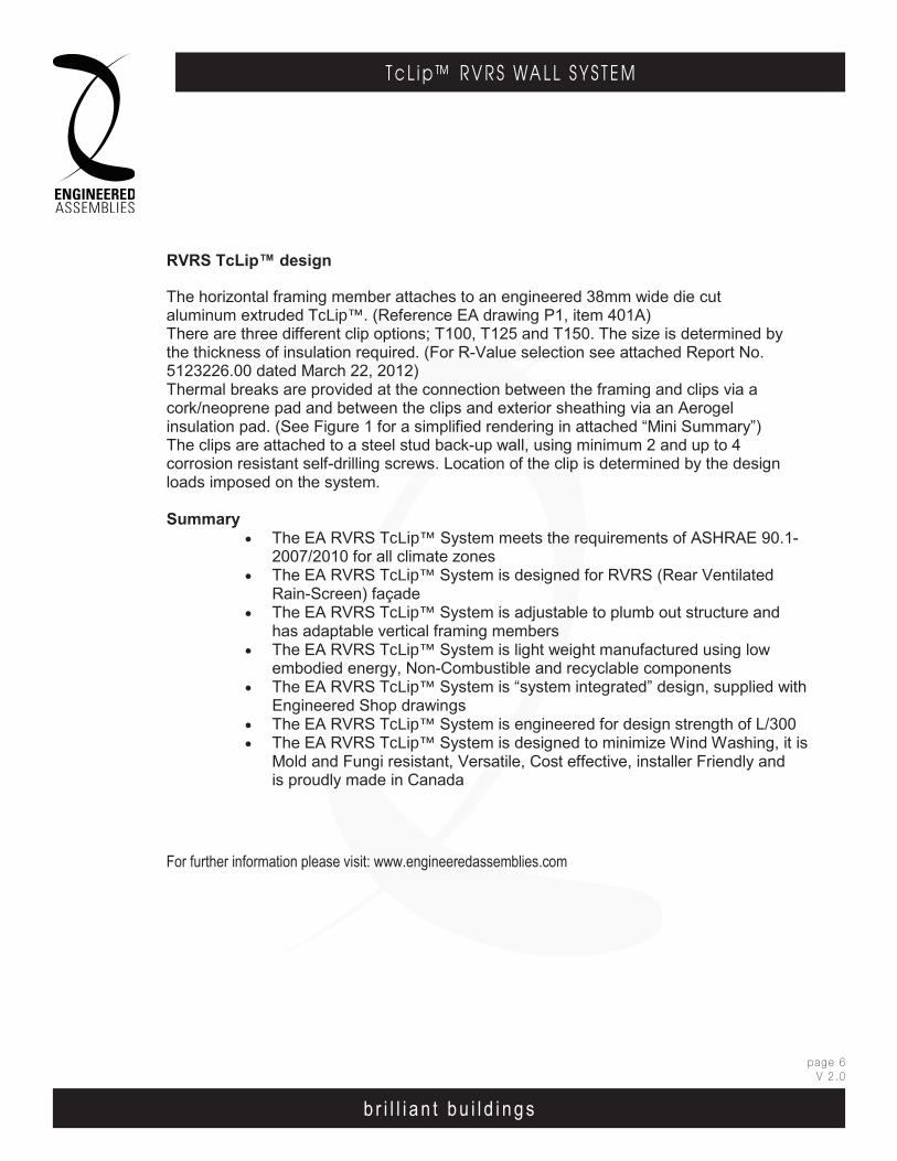
b r i l l i a n t b u i l d i n g s
page 6V 2 .0
T c L i p ™ R V R S WA L L S Y S T E M
b r i l l i a n t b u i l d i n g s
E . A . I . T h E r m A l C l I p r . V. r . S . WA l l S y S T E mEngineered Assembl ies Inc .6535 M i l l c reek D r i ve , Un i t 75M iss i ssauga , On ta r i o , Canada L5N 2M2
T 905 .816 .2218F 905 .816 .9761
E i n fo@eng inee redassemb l i es .comW Eng inee redAssemb l i es .com
page 503DEC13
November 18, 2013page 2 of 2
The horizontal framing member attaches to an engineered 38mm wide die cut aluminum extruded TcLip™. (Reference EA drawing P1, item 401A)There are three different clip options; T100, T125 and T150. The size is determined by the thickness of insulation required. (For R-Value selection see attached Report No. 5123226.00 dated March 22, 2012) Thermal breaks are provided at the connection between the framing and clips via a cork/neoprene pad and between the clips and exterior sheathing via an Aerogel insulation pad. (See Figure 1 for a simplified rendering in attached “Mini Summary”)The clips are attached to a steel stud back-up wall, using minimum 2 and up to 4 corrosion resistant self-drilling screws. Location of the clip is determined by the design loads imposed on the system.
Summary• The EA RVRS TcLip™ System meets the requirements of ASHRAE 90.1-
2007/2010 for all climate zones • The EA RVRS TcLip™ System is designed for RVRS (Rear Ventilated
Rain-Screen) façade • The EA RVRS TcLip™ System is adjustable to plumb out structure and
has adaptable vertical framing members • The EA RVRS TcLip™ System is light weight manufactured using low
embodied energy, Non-Combustible and recyclable components • The EA RVRS TcLip™ System is “system integrated” design, supplied with
Engineered Shop drawings • The EA RVRS TcLip™ System is engineered for design strength of L/300 • The EA RVRS TcLip™ System is designed to minimize Wind Washing, it is
Mold and Fungi resistant, Versatile, Cost effective, installer Friendly and is proudly made in Canada
For further information please visit: www.engineeredassemblies.com
Engineered Assemblies Inc.6535 Millcreek Drive, Unit 75Mississauga, Ontario, CanadaL5N 2M2
T 905.816.2218F 905.816.9761
E [email protected] EngineeredAssemblies.com
June 21, 2012
Engineered Assemblies (EA) RVRS TClip System
Executive SummaryIn response to the rapidly increasing demand for Thermally Effective wall assemblies to meet the evolving National Building Code, EA has designed a Thermal Clip System. EA RVRS T-Clip System comes in three clear field clip options; T100, T125 and T150, which accommodate 4”, 5”, and 6” of exterior mineral wool insulation (R-4.2/inch) respectively. The system is comprised of aluminum clips connected to horizontal and vertical sub-girts (framing members) that support Rear Ventilated Rain-Screen (RVRS) cladding panels. The clips are designed to attach to a steel stud back-up wall.
Thermal Performance The RVRS TClip System meets the prescriptive requirements for non-residential steel stud walls in ASHRAE 90.1-2007/2010 for all climate zones. Performance of the system is validated through Modeling and the Finite Element Analysis (FEA) package completed by Morrison Hershfield. The thermal solver and modeling procedures utilized for this study were extensively calibrated and validated for ASHRAE Research Project 1365-RP “Thermal Performance of Building Envelope Details for Mid- and High-Rise Construction (1365-RP)1. (for full report reference attached Report No. 5123226.00 dated March 22, 2012)
Structural PerformanceThe RVRS TClip System is engineered to accommodate Façade panels generally 8-26mm in thickness that require vertical back ventilation of minimum 25mm free air space. The system provides vertical framing members (reference EA drawing P1, part #292) that allow thermal expansion of both the vertical framing member and the movement of the panel. The vertical framing members are attached to horizontal framing members and may be positioned as required to accommodate panel fastener and vertical joint location. There is an EPDM gasket covering the face of the vertical framing member as a separator between the façade panel and the vertical Framing. The horizontal framing member (reference EA drawing P1, part #216) attaches to the TClip and can be adjusted to plumb out the structure. The spacing of the horizontal framing is adjustable to suite the design loads imposed on the system. Note: all framing members are made of pre=painted Black Z275 Grade A Galvanized Steel.
RVRS TcLip™ design
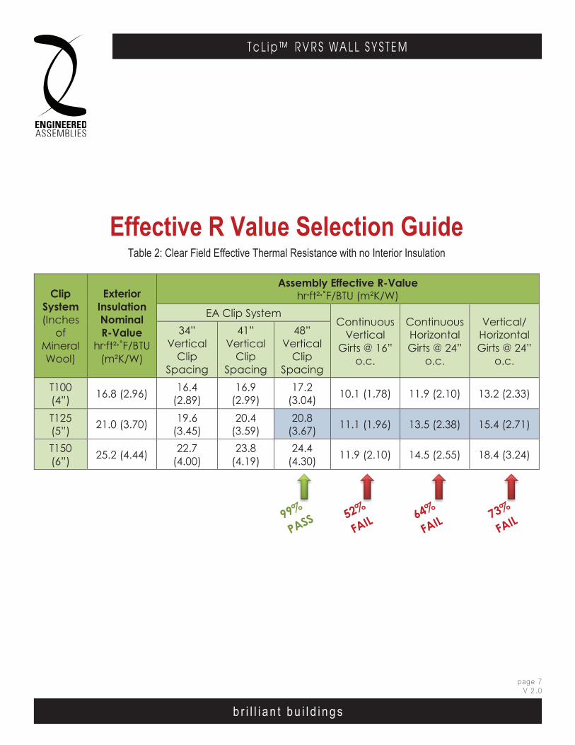
b r i l l i a n t b u i l d i n g s
page 7V 2 .0
T c L i p ™ R V R S WA L L S Y S T E M
Effective R Value Selection GuideTable 2: Clear Field Effective Thermal Resistance with no Interior Insulation
Clip System(Inches
of Mineral Wool)
Exterior Insulation Nominal R-Value
hrˑft²ˑ˚F/BTU(m²K/W)
Assembly Effective R-Valuehrˑft²ˑ˚F/BTU (m²K/W)
EA Clip SystemContinuous
Vertical Girts @ 16”
o.c.
Continuous Horizontal Girts @ 24”
o.c.
Vertical/HorizontalGirts @ 24”
o.c.
34”Vertical
Clip Spacing
41”Vertical
Clip Spacing
48”Vertical
Clip Spacing
T100(4”) 16.8 (2.96) 16.4
(2.89)16.9
(2.99)17.2
(3.04) 10.1 (1.78) 11.9 (2.10) 13.2 (2.33)
T125(5”) 21.0 (3.70) 19.6
(3.45)20.4
(3.59)20.8
(3.67) 11.1 (1.96) 13.5 (2.38) 15.4 (2.71)
T150(6”) 25.2 (4.44) 22.7
(4.00)23.8
(4.19)24.4
(4.30) 11.9 (2.10) 14.5 (2.55) 18.4 (3.24)
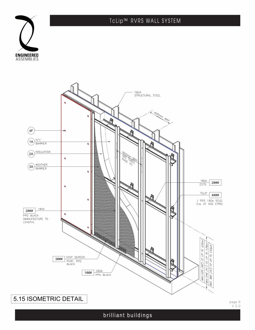
b r i l l i a n t b u i l d i n g s
page 8V 2 .0
T c L i p ™ R V R S WA L L S Y S T E M
b r i l l i a n t b u i l d i n g s
E . A . I . T h E r m A l C l I p r . V. r . S . WA l l S y S T E mEngineered Assembl ies Inc .6535 M i l l c reek D r i ve , Un i t 75M iss i ssauga , On ta r i o , Canada L5N 2M2
T 905 .816 .2218F 905 .816 .9761
E i n fo@eng inee redassemb l i es .comW Eng inee redAssemb l i es .com
page 703DEC13
5.15 ISOMETRIC DETAIL
4F
2###
2A
3A
1A
2###
4###
1###
3###

b r i l l i a n t b u i l d i n g s
page 9V 2 .0
T c L i p ™ R V R S WA L L S Y S T E M
b r i l l i a n t b u i l d i n g s
E . A . I . T h E r m A l C l I p r . V. r . S . WA l l S y S T E mEngineered Assembl ies Inc .6535 M i l l c reek D r i ve , Un i t 75M iss i ssauga , On ta r i o , Canada L5N 2M2
T 905 .816 .2218F 905 .816 .9761
E i n fo@eng inee redassemb l i es .comW Eng inee redAssemb l i es .com
page 803DEC13
b r i l l i a n t b u i l d i n g s
E . A . I . T h E r m A l C l I p r . V. r . S . WA l l S y S T E mEngineered Assembl ies Inc .6535 M i l l c reek D r i ve , Un i t 75M iss i ssauga , On ta r i o , Canada L5N 2M2
T 905 .816 .2218F 905 .816 .9761
E i n fo@eng inee redassemb l i es .comW Eng inee redAssemb l i es .com
page 2806OCT13
T100
ADjUsTMENT rANgE +5 -15
T100
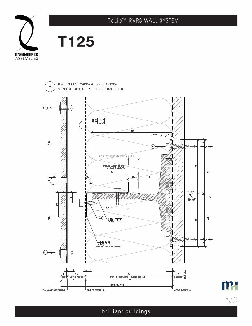
b r i l l i a n t b u i l d i n g s
page 10V 2 .0
T c L i p ™ R V R S WA L L S Y S T E M
b r i l l i a n t b u i l d i n g s
E . A . I . T h E r m A l C l I p r . V. r . S . WA l l S y S T E mEngineered Assembl ies Inc .6535 M i l l c reek D r i ve , Un i t 75M iss i ssauga , On ta r i o , Canada L5N 2M2
T 905 .816 .2218F 905 .816 .9761
E i n fo@eng inee redassemb l i es .comW Eng inee redAssemb l i es .com
page 903DEC13
b r i l l i a n t b u i l d i n g s
E . A . I . T h E r m A l C l I p r . V. r . S . WA l l S y S T E mEngineered Assembl ies Inc .6535 M i l l c reek D r i ve , Un i t 75M iss i ssauga , On ta r i o , Canada L5N 2M2
T 905 .816 .2218F 905 .816 .9761
E i n fo@eng inee redassemb l i es .comW Eng inee redAssemb l i es .com
page 2906OCT13
T125
ADjUsTMENT rANgE +5 -15
T125

b r i l l i a n t b u i l d i n g s
page 11V 2 .0
T c L i p ™ R V R S WA L L S Y S T E M
b r i l l i a n t b u i l d i n g s
E . A . I . T h E r m A l C l I p r . V. r . S . WA l l S y S T E mEngineered Assembl ies Inc .6535 M i l l c reek D r i ve , Un i t 75M iss i ssauga , On ta r i o , Canada L5N 2M2
T 905 .816 .2218F 905 .816 .9761
E i n fo@eng inee redassemb l i es .comW Eng inee redAssemb l i es .com
page 1003DEC13
b r i l l i a n t b u i l d i n g s
E . A . I . T h E r m A l C l I p r . V. r . S . WA l l S y S T E mEngineered Assembl ies Inc .6535 M i l l c reek D r i ve , Un i t 75M iss i ssauga , On ta r i o , Canada L5N 2M2
T 905 .816 .2218F 905 .816 .9761
E i n fo@eng inee redassemb l i es .comW Eng inee redAssemb l i es .com
page 3006OCT13
T150
ADjUsTMENT rANgE +5 -15
T150
b r i l l i a n t b u i l d i n g s
page 12V 2 .0
T c L i p ™ R V R S WA L L S Y S T E M
b r i l l i a n t b u i l d i n g s
E . A . I . T h E r m A l C l I p r . V. r . S . WA l l S y S T E mEngineered Assembl ies Inc .6535 M i l l c reek D r i ve , Un i t 75M iss i ssauga , On ta r i o , Canada L5N 2M2
T 905 .816 .2218F 905 .816 .9761
E i n fo@eng inee redassemb l i es .comW Eng inee redAssemb l i es .com
page 1103DEC13
Structura l Report
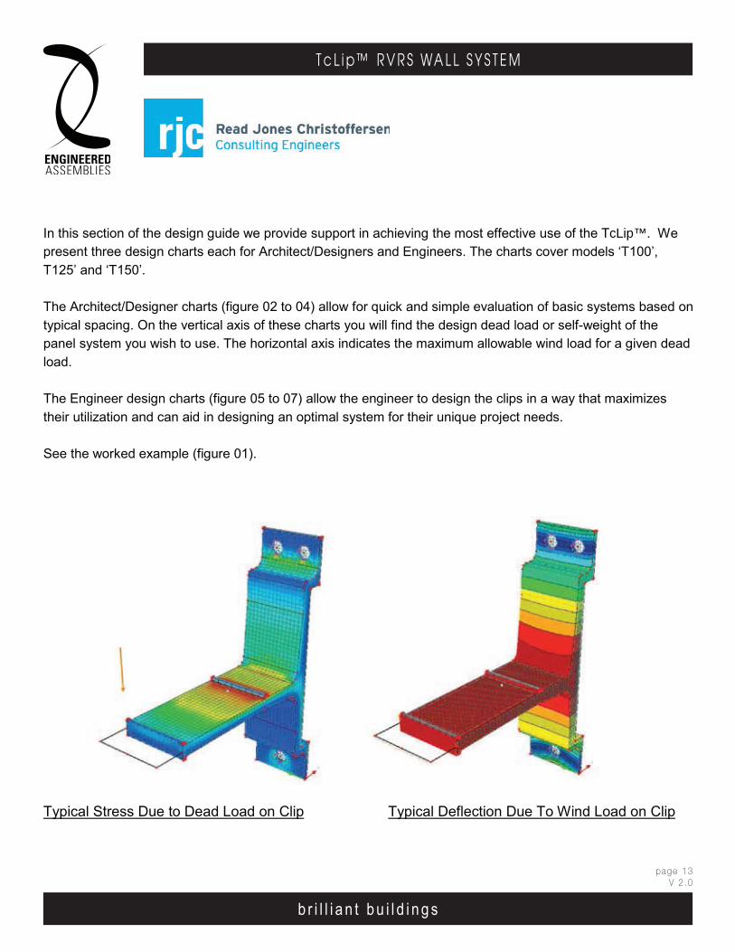
b r i l l i a n t b u i l d i n g s
page 13V 2 .0
T c L i p ™ R V R S WA L L S Y S T E M
b r i l l i a n t b u i l d i n g s
E . A . I . T h E r m A l C l I p r . V. r . S . WA l l S y S T E mEngineered Assembl ies Inc .6535 M i l l c reek D r i ve , Un i t 75M iss i ssauga , On ta r i o , Canada L5N 2M2
T 905 .816 .2218F 905 .816 .9761
E i n fo@eng inee redassemb l i es .comW Eng inee redAssemb l i es .com
page 1203DEC13
E . A . I . T h E r m A l C l I p r . V. r . S . WA l l S y S T E mEngineered Assembl ies Inc .6535 M i l l c reek D r i ve , Un i t 75M iss i ssauga , On ta r i o , Canada L5N 2M2
T 905 .816 .2218F 905 .816 .9761
E i n fo@eng inee redassemb l i es .comW Eng inee redAssemb l i es .com
b r i l l i a n t b u i l d i n g s
E . A . I . T h E r m A l C l I p r . V. r . S . WA l l S y S T E mEngineered Assembl ies Inc .6535 M i l l c reek D r i ve , Un i t 75M iss i ssauga , On ta r i o , Canada L5N 2M2
T 905 .816 .2218F 905 .816 .9761
E i n fo@eng inee redassemb l i es .comW Eng inee redAssemb l i es .com
page 306OCT13
b r i l l i a n t b u i l d i n g s
E . A . I . T h E r m A l C l I p r . V. r . S . WA l l S y S T E m6535 M i l l c reek D r i ve , Un i t 75M iss i ssauga , On ta r i o , Canada L5N 2M2
T 905 .816 .2218F 905 .816 .9761
E i n fo@eng inee redassemb l i es .comW Eng inee redAssemb l i es .com
6 5 3 5 M i l l c re ek D r i v e , U n i t 7 5M is s i ss au g a , On ta r io , C an a da L 5 N 2M 2
T 9 0 5 .81 6F 9 0 5 .81 6 .97 6 1
Ei n fo@ e ng i ne e red as se mb l ie s .c omW E n g i n ee re dAs se mb l ie s .co m
E . A . I . T H E R M A L C L I P . V . R . S . W A L L S Y S T E M
b r i l l i a n t b u i l d i n g s
In this section of the design guide we provide support in achieving the most effective use of the TcLip™. We present three design charts each for Architect/Designers and Engineers. The charts cover models ‘T100’, T125’ and ‘T150’.
The Architect/Designer charts (figure 02 to 04) allow for quick and simple evaluation of basic systems based on typical spacing. On the vertical axis of these charts you will find the design dead load or self-weight of the panel system you wish to use. The horizontal axis indicates the maximum allowable wind load for a given deadload.
The Engineer design charts (figure 05 to 07) allow the engineer to design the clips in a way that maximizes their utilization and can aid in designing an optimal system for their unique project needs.
See the worked example (figure 01).
Typical Stress Due to Dead Load on Clip Typical Deflection Due To Wind Load on Clip
Sheet ix03MAY13
sheet ix06MAY13

b r i l l i a n t b u i l d i n g s
page 14V 2 .0
T c L i p ™ R V R S WA L L S Y S T E M
b r i l l i a n t b u i l d i n g s
E . A . I . T h E r m A l C l I p r . V. r . S . WA l l S y S T E mEngineered Assembl ies Inc .6535 M i l l c reek D r i ve , Un i t 75M iss i ssauga , On ta r i o , Canada L5N 2M2
T 905 .816 .2218F 905 .816 .9761
E i n fo@eng inee redassemb l i es .comW Eng inee redAssemb l i es .com
page 1303DEC13
E . A . I . T h E r m A l C l I p r . V. r . S . WA l l S y S T E mEngineered Assembl ies Inc .6535 M i l l c reek D r i ve , Un i t 75M iss i ssauga , On ta r i o , Canada L5N 2M2
T 905 .816 .2218F 905 .816 .9761
E i n fo@eng inee redassemb l i es .comW Eng inee redAssemb l i es .com
b r i l l i a n t b u i l d i n g s
E . A . I . T h E r m A l C l I p r . V. r . S . WA l l S y S T E mEngineered Assembl ies Inc .6535 M i l l c reek D r i ve , Un i t 75M iss i ssauga , On ta r i o , Canada L5N 2M2
T 905 .816 .2218F 905 .816 .9761
E i n fo@eng inee redassemb l i es .comW Eng inee redAssemb l i es .com
page 406OCT13
b r i l l i a n t b u i l d i n g s
E . A . I . T h E r m A l C l I p r . V. r . S . WA l l S y S T E m6535 M i l l c reek D r i ve , Un i t 75M iss i ssauga , On ta r i o , Canada L5N 2M2
T 905 .816 .2218F 905 .816 .9761
E i n fo@eng inee redassemb l i es .comW Eng inee redAssemb l i es .com
6 5 3 5 M i l l c re ek D r i v e , U n i t 7 5M is s i ss au g a , On ta r io , C an a da L 5 N 2M 2
T 9 0 5 .81 6F 9 0 5 .81 6 .97 6 1
Ei n fo@ e ng i ne e red as se mb l ie s .c omW E n g i n ee re dAs se mb l ie s .co m
E . A . I . T H E R M A L C L I P . V . R . S . W A L L S Y S T E M
b r i l l i a n t b u i l d i n g s
Figure 01: Worked Example for a ‘T125’ Clip
In this example the panel that we are designing for has a dead load or self-weight of 1.25 kPa., and we want to know if the system can take a wind load of 35 PSF. We would like to have a space of 125mm (5”) so we can have 4” of insolation and 1” air space behind the panel. The layout of the girts are as shown on the design guide and spaced horizontally 16” apart and vertically 48” apart.
As we can see from the chart the maximum wind load in this case is over 101 PSF and well above the required 35 PSF and therefore the clip will work in this application.
Sheet x03MAY13
sheet x06MAY13
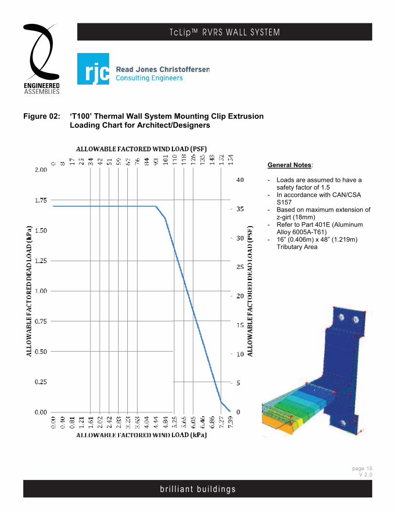
b r i l l i a n t b u i l d i n g s
page 15V 2 .0
T c L i p ™ R V R S WA L L S Y S T E M
b r i l l i a n t b u i l d i n g s
E . A . I . T h E r m A l C l I p r . V. r . S . WA l l S y S T E mEngineered Assembl ies Inc .6535 M i l l c reek D r i ve , Un i t 75M iss i ssauga , On ta r i o , Canada L5N 2M2
T 905 .816 .2218F 905 .816 .9761
E i n fo@eng inee redassemb l i es .comW Eng inee redAssemb l i es .com
page 1403DEC13
E . A . I . T h E r m A l C l I p r . V. r . S . WA l l S y S T E mEngineered Assembl ies Inc .6535 M i l l c reek D r i ve , Un i t 75M iss i ssauga , On ta r i o , Canada L5N 2M2
T 905 .816 .2218F 905 .816 .9761
E i n fo@eng inee redassemb l i es .comW Eng inee redAssemb l i es .com
b r i l l i a n t b u i l d i n g s
E . A . I . T h E r m A l C l I p r . V. r . S . WA l l S y S T E mEngineered Assembl ies Inc .6535 M i l l c reek D r i ve , Un i t 75M iss i ssauga , On ta r i o , Canada L5N 2M2
T 905 .816 .2218F 905 .816 .9761
E i n fo@eng inee redassemb l i es .comW Eng inee redAssemb l i es .com
page 506OCT13
b r i l l i a n t b u i l d i n g s
E . A . I . T h E r m A l C l I p r . V. r . S . WA l l S y S T E m6535 M i l l c reek D r i ve , Un i t 75M iss i ssauga , On ta r i o , Canada L5N 2M2
T 905 .816 .2218F 905 .816 .9761
E i n fo@eng inee redassemb l i es .comW Eng inee redAssemb l i es .com
6 5 3 5 M i l l c re ek D r i v e , U n i t 7 5M is s i ss au g a , On ta r io , C an a da L 5 N 2M 2
T 9 0 5 .81 6F 9 0 5 .81 6 .97 6 1
Ei n fo@ e ng i ne e red as se mb l ie s .c omW E n g i n ee re dAs se mb l ie s .co m
E . A . I . T H E R M A L C L I P . V . R . S . W A L L S Y S T E M
b r i l l i a n t b u i l d i n g s
Figure 02: ‘T100’ Thermal Wall System Mounting Clip ExtrusionLoading Chart for Architect/Designers
Sheet xi03MAY13
General Notes:
- Loads are assumed to have a safety factor of 1.5
- In accordance with CAN/CSA S157
- Based on maximum extension of z-girt (18mm)
- Refer to Part 401E (Aluminum Alloy 6005A-T61)
- 16” (0.406m) x 48” (1.219m) Tributary Area
sheet xi06MAY13
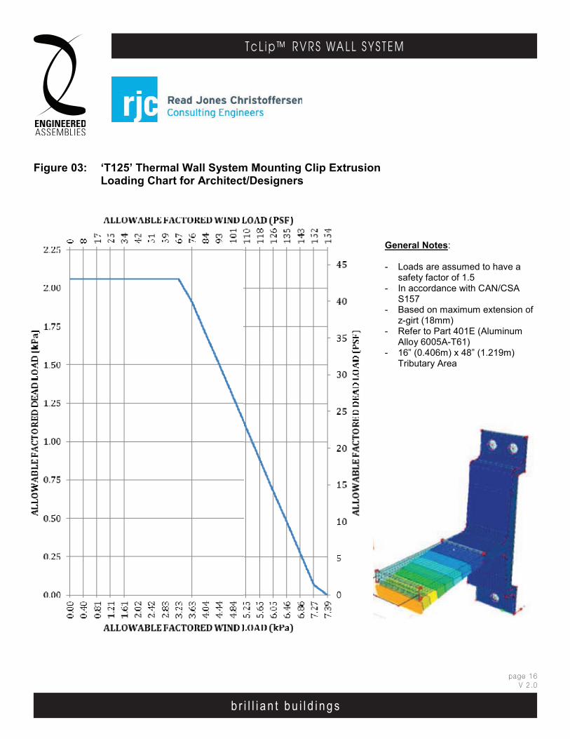
b r i l l i a n t b u i l d i n g s
page 16V 2 .0
T c L i p ™ R V R S WA L L S Y S T E M
b r i l l i a n t b u i l d i n g s
E . A . I . T h E r m A l C l I p r . V. r . S . WA l l S y S T E mEngineered Assembl ies Inc .6535 M i l l c reek D r i ve , Un i t 75M iss i ssauga , On ta r i o , Canada L5N 2M2
T 905 .816 .2218F 905 .816 .9761
E i n fo@eng inee redassemb l i es .comW Eng inee redAssemb l i es .com
page 1503DEC13
E . A . I . T h E r m A l C l I p r . V. r . S . WA l l S y S T E mEngineered Assembl ies Inc .6535 M i l l c reek D r i ve , Un i t 75M iss i ssauga , On ta r i o , Canada L5N 2M2
T 905 .816 .2218F 905 .816 .9761
E i n fo@eng inee redassemb l i es .comW Eng inee redAssemb l i es .com
b r i l l i a n t b u i l d i n g s
E . A . I . T h E r m A l C l I p r . V. r . S . WA l l S y S T E mEngineered Assembl ies Inc .6535 M i l l c reek D r i ve , Un i t 75M iss i ssauga , On ta r i o , Canada L5N 2M2
T 905 .816 .2218F 905 .816 .9761
E i n fo@eng inee redassemb l i es .comW Eng inee redAssemb l i es .com
page 606OCT13
b r i l l i a n t b u i l d i n g s
E . A . I . T h E r m A l C l I p r . V. r . S . WA l l S y S T E m6535 M i l l c reek D r i ve , Un i t 75M iss i ssauga , On ta r i o , Canada L5N 2M2
T 905 .816 .2218F 905 .816 .9761
E i n fo@eng inee redassemb l i es .comW Eng inee redAssemb l i es .com
6 5 3 5 M i l l c re ek D r i v e , U n i t 7 5M is s i ss au g a , On ta r io , C an a da L 5 N 2M 2
T 9 0 5 .81 6F 9 0 5 .81 6 .97 6 1
Ei n fo@ e ng i ne e red as se mb l ie s .c omW E n g i n ee re dAs se mb l ie s .co m
E . A . I . T H E R M A L C L I P . V . R . S . W A L L S Y S T E M
b r i l l i a n t b u i l d i n g s
Figure 03: ‘T125’ Thermal Wall System Mounting Clip ExtrusionLoading Chart for Architect/Designers
Sheet xii03MAY13
General Notes:
- Loads are assumed to have a safety factor of 1.5
- In accordance with CAN/CSA S157
- Based on maximum extension of z-girt (18mm)
- Refer to Part 401E (Aluminum Alloy 6005A-T61)
- 16” (0.406m) x 48” (1.219m) Tributary Area
sheet xii06MAY13
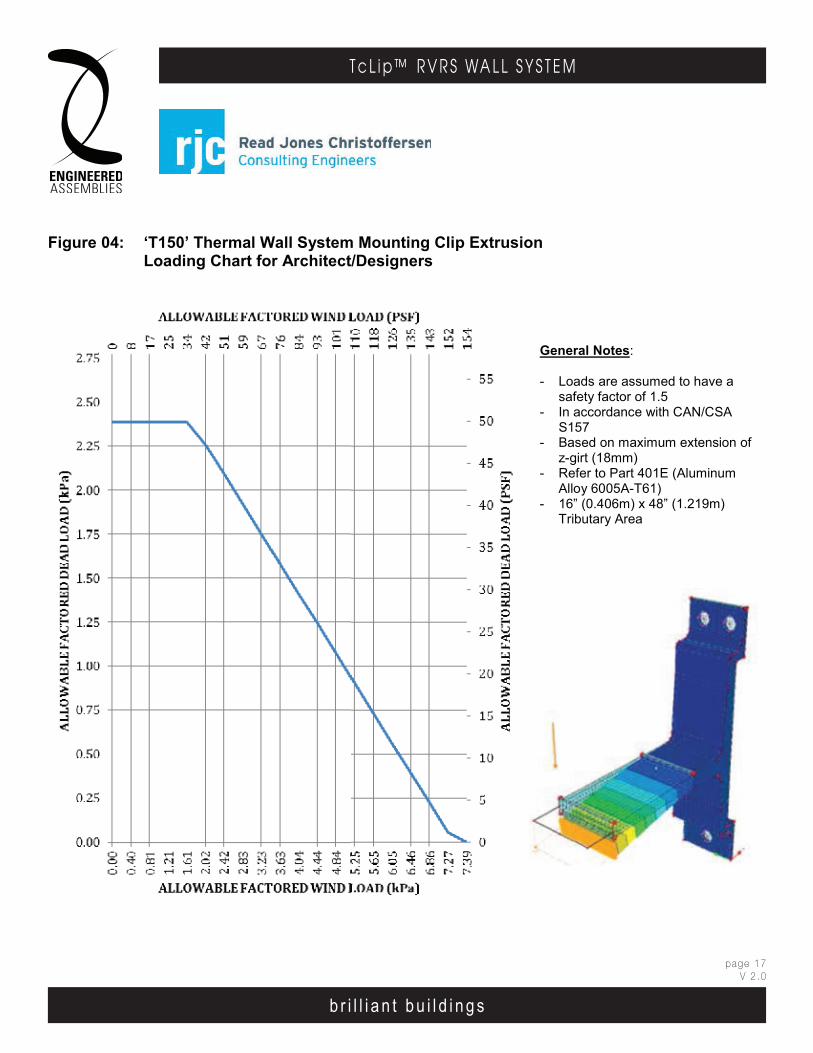
b r i l l i a n t b u i l d i n g s
page 17V 2 .0
T c L i p ™ R V R S WA L L S Y S T E M
b r i l l i a n t b u i l d i n g s
E . A . I . T h E r m A l C l I p r . V. r . S . WA l l S y S T E mEngineered Assembl ies Inc .6535 M i l l c reek D r i ve , Un i t 75M iss i ssauga , On ta r i o , Canada L5N 2M2
T 905 .816 .2218F 905 .816 .9761
E i n fo@eng inee redassemb l i es .comW Eng inee redAssemb l i es .com
page 1603DEC13
E . A . I . T h E r m A l C l I p r . V. r . S . WA l l S y S T E mEngineered Assembl ies Inc .6535 M i l l c reek D r i ve , Un i t 75M iss i ssauga , On ta r i o , Canada L5N 2M2
T 905 .816 .2218F 905 .816 .9761
E i n fo@eng inee redassemb l i es .comW Eng inee redAssemb l i es .com
b r i l l i a n t b u i l d i n g s
E . A . I . T h E r m A l C l I p r . V. r . S . WA l l S y S T E mEngineered Assembl ies Inc .6535 M i l l c reek D r i ve , Un i t 75M iss i ssauga , On ta r i o , Canada L5N 2M2
T 905 .816 .2218F 905 .816 .9761
E i n fo@eng inee redassemb l i es .comW Eng inee redAssemb l i es .com
page 706OCT13
b r i l l i a n t b u i l d i n g s
E . A . I . T h E r m A l C l I p r . V. r . S . WA l l S y S T E m6535 M i l l c reek D r i ve , Un i t 75M iss i ssauga , On ta r i o , Canada L5N 2M2
T 905 .816 .2218F 905 .816 .9761
E i n fo@eng inee redassemb l i es .comW Eng inee redAssemb l i es .com
6 5 3 5 M i l l c re ek D r i v e , U n i t 7 5M is s i ss au g a , On ta r io , C an a da L 5 N 2M 2
T 9 0 5 .81 6F 9 0 5 .81 6 .97 6 1
Ei n fo@ e ng i ne e red as se mb l ie s .c omW E n g i n ee re dAs se mb l ie s .co m
E . A . I . T H E R M A L C L I P . V . R . S . W A L L S Y S T E M
b r i l l i a n t b u i l d i n g s
Figure 04: ‘T150’ Thermal Wall System Mounting Clip ExtrusionLoading Chart for Architect/Designers
Sheet xiii03MAY13
General Notes:
- Loads are assumed to have a safety factor of 1.5
- In accordance with CAN/CSA S157
- Based on maximum extension of z-girt (18mm)
- Refer to Part 401E (Aluminum Alloy 6005A-T61)
- 16” (0.406m) x 48” (1.219m) Tributary Area
sheet xiii06MAY13
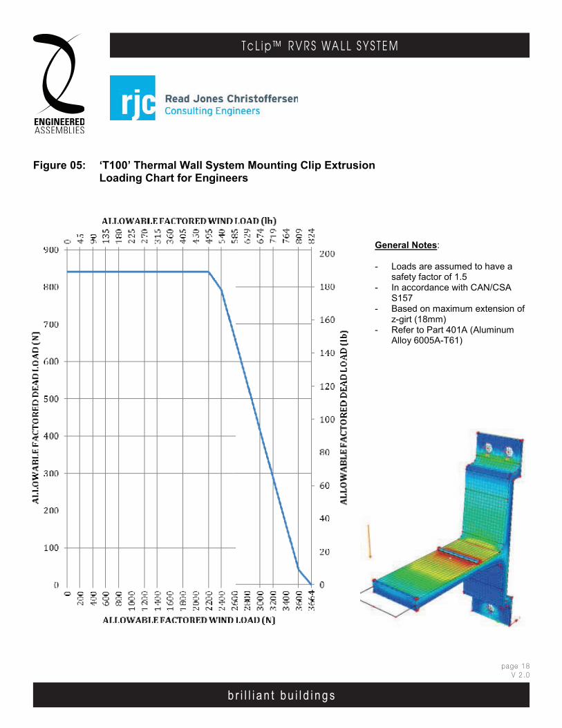
b r i l l i a n t b u i l d i n g s
page 18V 2 .0
T c L i p ™ R V R S WA L L S Y S T E M
b r i l l i a n t b u i l d i n g s
E . A . I . T h E r m A l C l I p r . V. r . S . WA l l S y S T E mEngineered Assembl ies Inc .6535 M i l l c reek D r i ve , Un i t 75M iss i ssauga , On ta r i o , Canada L5N 2M2
T 905 .816 .2218F 905 .816 .9761
E i n fo@eng inee redassemb l i es .comW Eng inee redAssemb l i es .com
page 1703DEC13
E . A . I . T h E r m A l C l I p r . V. r . S . WA l l S y S T E mEngineered Assembl ies Inc .6535 M i l l c reek D r i ve , Un i t 75M iss i ssauga , On ta r i o , Canada L5N 2M2
T 905 .816 .2218F 905 .816 .9761
E i n fo@eng inee redassemb l i es .comW Eng inee redAssemb l i es .com
b r i l l i a n t b u i l d i n g s
E . A . I . T h E r m A l C l I p r . V. r . S . WA l l S y S T E mEngineered Assembl ies Inc .6535 M i l l c reek D r i ve , Un i t 75M iss i ssauga , On ta r i o , Canada L5N 2M2
T 905 .816 .2218F 905 .816 .9761
E i n fo@eng inee redassemb l i es .comW Eng inee redAssemb l i es .com
page 806OCT13
b r i l l i a n t b u i l d i n g s
E . A . I . T h E r m A l C l I p r . V. r . S . WA l l S y S T E m6535 M i l l c reek D r i ve , Un i t 75M iss i ssauga , On ta r i o , Canada L5N 2M2
T 905 .816 .2218F 905 .816 .9761
E i n fo@eng inee redassemb l i es .comW Eng inee redAssemb l i es .com
6 5 3 5 M i l l c re ek D r i v e , U n i t 7 5M is s i ss au g a , On ta r io , C an a da L 5 N 2M 2
T 9 0 5 .81 6F 9 0 5 .81 6 .97 6 1
Ei n fo@ e ng i ne e red as se mb l ie s .c omW E n g i n ee re dAs se mb l ie s .co m
E . A . I . T H E R M A L C L I P . V . R . S . W A L L S Y S T E M
b r i l l i a n t b u i l d i n g s
Figure 05: ‘T100’ Thermal Wall System Mounting Clip ExtrusionLoading Chart for Engineers
Sheet xiv03MAY13
General Notes:
- Loads are assumed to have a safety factor of 1.5
- In accordance with CAN/CSA S157
- Based on maximum extension of z-girt (18mm)
- Refer to Part 401A (Aluminum Alloy 6005A-T61)
sheet xiv06MAY13
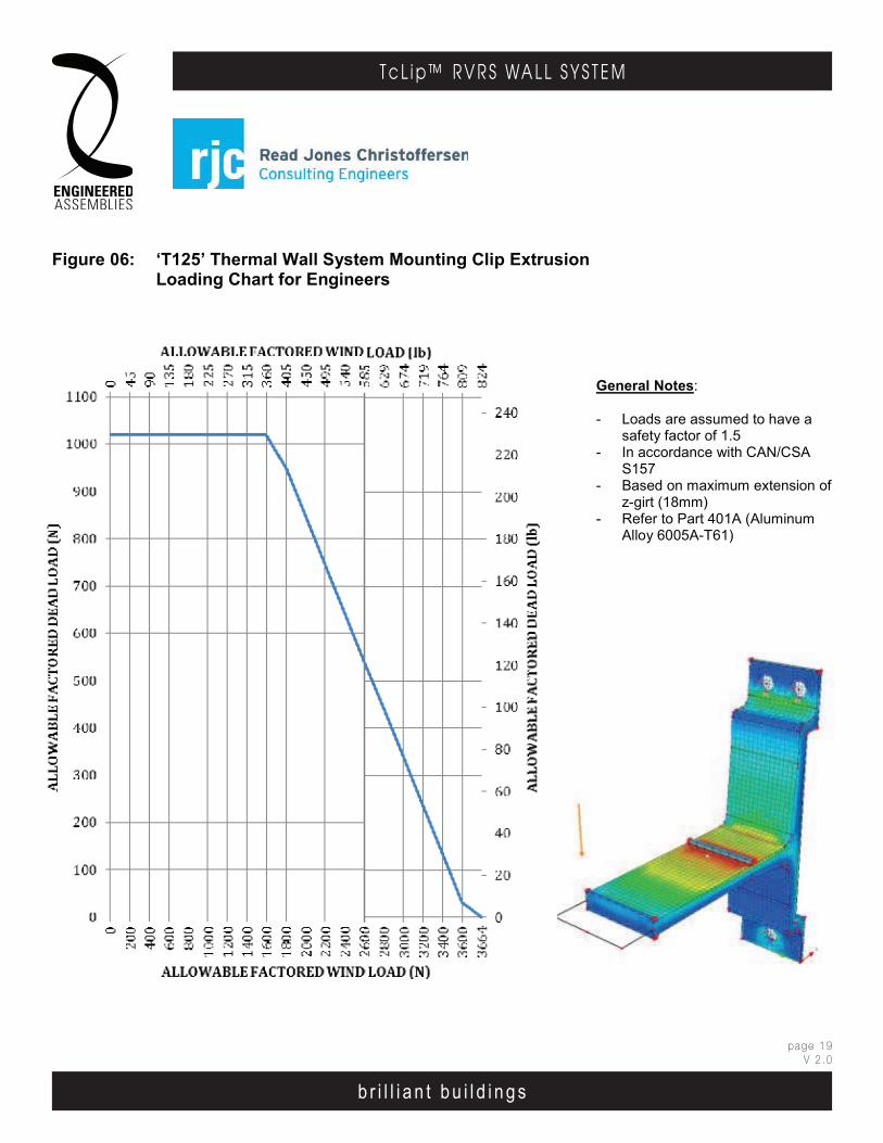
b r i l l i a n t b u i l d i n g s
page 19V 2 .0
T c L i p ™ R V R S WA L L S Y S T E M
b r i l l i a n t b u i l d i n g s
E . A . I . T h E r m A l C l I p r . V. r . S . WA l l S y S T E mEngineered Assembl ies Inc .6535 M i l l c reek D r i ve , Un i t 75M iss i ssauga , On ta r i o , Canada L5N 2M2
T 905 .816 .2218F 905 .816 .9761
E i n fo@eng inee redassemb l i es .comW Eng inee redAssemb l i es .com
page 1803DEC13
E . A . I . T h E r m A l C l I p r . V. r . S . WA l l S y S T E mEngineered Assembl ies Inc .6535 M i l l c reek D r i ve , Un i t 75M iss i ssauga , On ta r i o , Canada L5N 2M2
T 905 .816 .2218F 905 .816 .9761
E i n fo@eng inee redassemb l i es .comW Eng inee redAssemb l i es .com
b r i l l i a n t b u i l d i n g s
E . A . I . T h E r m A l C l I p r . V. r . S . WA l l S y S T E mEngineered Assembl ies Inc .6535 M i l l c reek D r i ve , Un i t 75M iss i ssauga , On ta r i o , Canada L5N 2M2
T 905 .816 .2218F 905 .816 .9761
E i n fo@eng inee redassemb l i es .comW Eng inee redAssemb l i es .com
page 906OCT13
b r i l l i a n t b u i l d i n g s
E . A . I . T h E r m A l C l I p r . V. r . S . WA l l S y S T E m6535 M i l l c reek D r i ve , Un i t 75M iss i ssauga , On ta r i o , Canada L5N 2M2
T 905 .816 .2218F 905 .816 .9761
E i n fo@eng inee redassemb l i es .comW Eng inee redAssemb l i es .com
6 5 3 5 M i l l c re ek D r i v e , U n i t 7 5M is s i ss au g a , On ta r io , C an a da L 5 N 2M 2
T 9 0 5 .81 6F 9 0 5 .81 6 .97 6 1
Ei n fo@ e ng i ne e red as se mb l ie s .c omW E n g i n ee re dAs se mb l ie s .co m
E . A . I . T H E R M A L C L I P . V . R . S . W A L L S Y S T E M
b r i l l i a n t b u i l d i n g s
Figure 06: ‘T125’ Thermal Wall System Mounting Clip ExtrusionLoading Chart for Engineers
Sheet xv03MAY13
General Notes:
- Loads are assumed to have a safety factor of 1.5
- In accordance with CAN/CSA S157
- Based on maximum extension of z-girt (18mm)
- Refer to Part 401A (Aluminum Alloy 6005A-T61)
sheet xv06MAY13
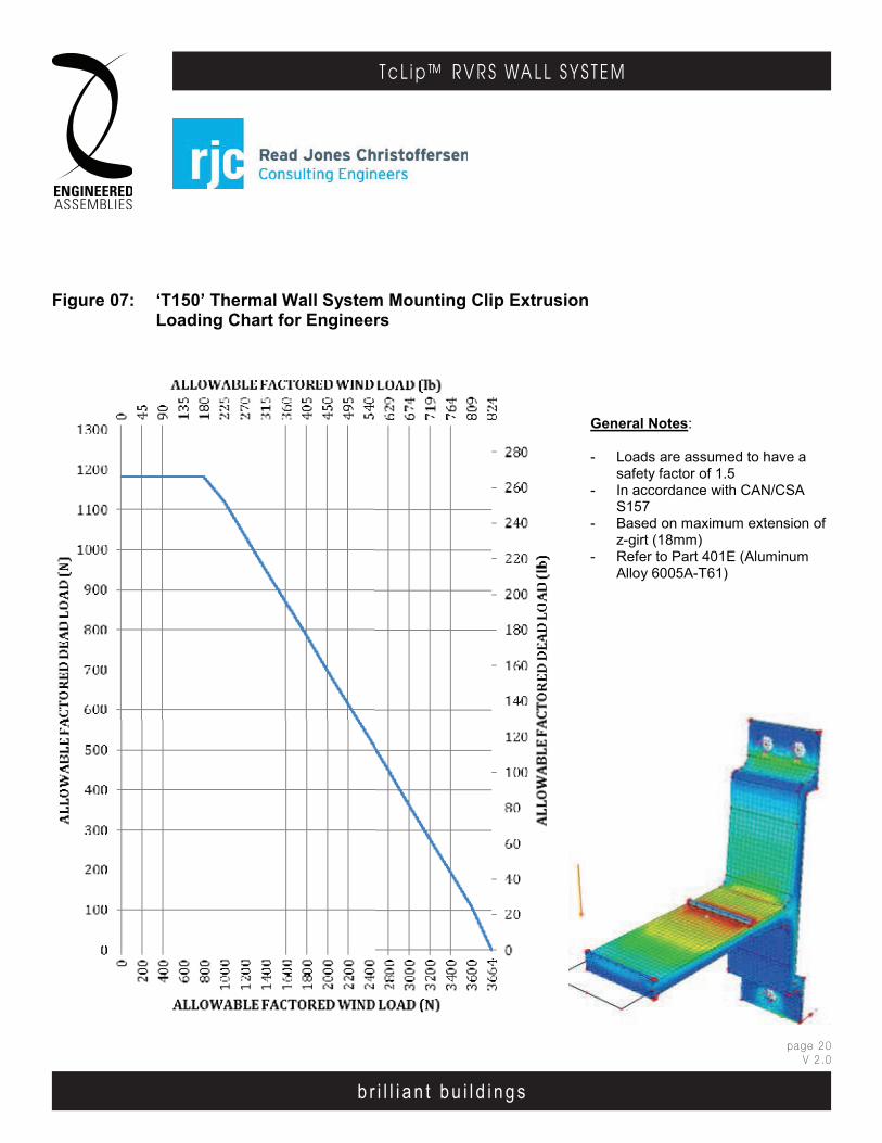
b r i l l i a n t b u i l d i n g s
page 20V 2 .0
T c L i p ™ R V R S WA L L S Y S T E M
b r i l l i a n t b u i l d i n g s
E . A . I . T h E r m A l C l I p r . V. r . S . WA l l S y S T E mEngineered Assembl ies Inc .6535 M i l l c reek D r i ve , Un i t 75M iss i ssauga , On ta r i o , Canada L5N 2M2
T 905 .816 .2218F 905 .816 .9761
E i n fo@eng inee redassemb l i es .comW Eng inee redAssemb l i es .com
page 1903DEC13
E . A . I . T h E r m A l C l I p r . V. r . S . WA l l S y S T E mEngineered Assembl ies Inc .6535 M i l l c reek D r i ve , Un i t 75M iss i ssauga , On ta r i o , Canada L5N 2M2
T 905 .816 .2218F 905 .816 .9761
E i n fo@eng inee redassemb l i es .comW Eng inee redAssemb l i es .com
b r i l l i a n t b u i l d i n g s
E . A . I . T h E r m A l C l I p r . V. r . S . WA l l S y S T E mEngineered Assembl ies Inc .6535 M i l l c reek D r i ve , Un i t 75M iss i ssauga , On ta r i o , Canada L5N 2M2
T 905 .816 .2218F 905 .816 .9761
E i n fo@eng inee redassemb l i es .comW Eng inee redAssemb l i es .com
page 1006OCT13
b r i l l i a n t b u i l d i n g s
E . A . I . T h E r m A l C l I p r . V. r . S . WA l l S y S T E m6535 M i l l c reek D r i ve , Un i t 75M iss i ssauga , On ta r i o , Canada L5N 2M2
T 905 .816 .2218F 905 .816 .9761
E i n fo@eng inee redassemb l i es .comW Eng inee redAssemb l i es .com
6 5 3 5 M i l l c re ek D r i v e , U n i t 7 5M is s i ss au g a , On ta r io , C an a da L 5 N 2M 2
T 9 0 5 .81 6F 9 0 5 .81 6 .97 6 1
Ei n fo@ e ng i ne e red as se mb l ie s .c omW E n g i n ee re dAs se mb l ie s .co m
E . A . I . T H E R M A L C L I P . V . R . S . W A L L S Y S T E M
b r i l l i a n t b u i l d i n g s
Figure 07: ‘T150’ Thermal Wall System Mounting Clip ExtrusionLoading Chart for Engineers
Sheet xvi03MAY13
General Notes:
- Loads are assumed to have a safety factor of 1.5
- In accordance with CAN/CSA S157
- Based on maximum extension of z-girt (18mm)
- Refer to Part 401E (Aluminum Alloy 6005A-T61)
sheet xvi06MAY13
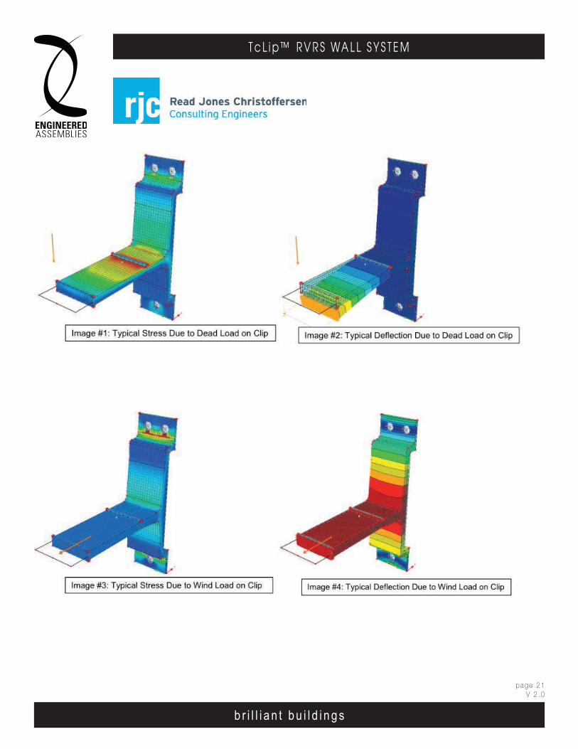
b r i l l i a n t b u i l d i n g s
page 21V 2 .0
T c L i p ™ R V R S WA L L S Y S T E M
b r i l l i a n t b u i l d i n g s
E . A . I . T h E r m A l C l I p r . V. r . S . WA l l S y S T E mEngineered Assembl ies Inc .6535 M i l l c reek D r i ve , Un i t 75M iss i ssauga , On ta r i o , Canada L5N 2M2
T 905 .816 .2218F 905 .816 .9761
E i n fo@eng inee redassemb l i es .comW Eng inee redAssemb l i es .com
page 2003DEC13
E . A . I . T h E r m A l C l I p r . V. r . S . WA l l S y S T E mEngineered Assembl ies Inc .6535 M i l l c reek D r i ve , Un i t 75M iss i ssauga , On ta r i o , Canada L5N 2M2
T 905 .816 .2218F 905 .816 .9761
E i n fo@eng inee redassemb l i es .comW Eng inee redAssemb l i es .com
b r i l l i a n t b u i l d i n g s
E . A . I . T h E r m A l C l I p r . V. r . S . WA l l S y S T E mEngineered Assembl ies Inc .6535 M i l l c reek D r i ve , Un i t 75M iss i ssauga , On ta r i o , Canada L5N 2M2
T 905 .816 .2218F 905 .816 .9761
E i n fo@eng inee redassemb l i es .comW Eng inee redAssemb l i es .com
page 1106OCT13
b r i l l i a n t b u i l d i n g s
E . A . I . T h E r m A l C l I p r . V. r . S . WA l l S y S T E m6535 M i l l c reek D r i ve , Un i t 75M iss i ssauga , On ta r i o , Canada L5N 2M2
T 905 .816 .2218F 905 .816 .9761
E i n fo@eng inee redassemb l i es .comW Eng inee redAssemb l i es .com
6 5 3 5 M i l l c re ek D r i v e , U n i t 7 5M is s i ss au g a , On ta r io , C an a da L 5 N 2M 2
T 9 0 5 .81 6F 9 0 5 .81 6 .97 6 1
Ei n fo@ e ng i ne e red as se mb l ie s .c omW E n g i n ee re dAs se mb l ie s .co m
E . A . I . T H E R M A L C L I P . V . R . S . W A L L S Y S T E M
b r i l l i a n t b u i l d i n g s
Sheet xvii03MAY13
sheet xvii06MAY13
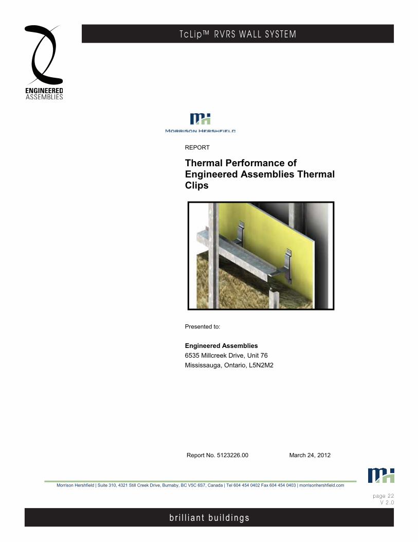
b r i l l i a n t b u i l d i n g s
page 22V 2 .0
T c L i p ™ R V R S WA L L S Y S T E M
b r i l l i a n t b u i l d i n g s
E . A . I . T h E r m A l C l I p r . V. r . S . WA l l S y S T E mEngineered Assembl ies Inc .6535 M i l l c reek D r i ve , Un i t 75M iss i ssauga , On ta r i o , Canada L5N 2M2
T 905 .816 .2218F 905 .816 .9761
E i n fo@eng inee redassemb l i es .comW Eng inee redAssemb l i es .com
page 2103DEC13
b r i l l i a n t b u i l d i n g s
E . A . I . T h E r m A l C l I p r . V. r . S . WA l l S y S T E mEngineered Assembl ies Inc .6535 M i l l c reek D r i ve , Un i t 75M iss i ssauga , On ta r i o , Canada L5N 2M2
T 905 .816 .2218F 905 .816 .9761
E i n fo@eng inee redassemb l i es .comW Eng inee redAssemb l i es .com
page 1206OCT13
Morrison Hershfield | Suite 310, 4321 Still Creek Drive, Burnaby, BC V5C 6S7, Canada | Tel 604 454 0402 Fax 604 454 0403 | morrisonhershfield.com
REPORT
Thermal Performance of Engineered Assemblies Thermal Clips
Presented to: Engineered Assemblies 6535 Millcreek Drive, Unit 76 Mississauga, Ontario, L5N2M2
Report No. 5123226.00 March 24, 2012

b r i l l i a n t b u i l d i n g s
page 23V 2 .0
T c L i p ™ R V R S WA L L S Y S T E M
b r i l l i a n t b u i l d i n g s
E . A . I . T h E r m A l C l I p r . V. r . S . WA l l S y S T E mEngineered Assembl ies Inc .6535 M i l l c reek D r i ve , Un i t 75M iss i ssauga , On ta r i o , Canada L5N 2M2
T 905 .816 .2218F 905 .816 .9761
E i n fo@eng inee redassemb l i es .comW Eng inee redAssemb l i es .com
page 2203DEC13
b r i l l i a n t b u i l d i n g s
E . A . I . T h E r m A l C l I p r . V. r . S . WA l l S y S T E mEngineered Assembl ies Inc .6535 M i l l c reek D r i ve , Un i t 75M iss i ssauga , On ta r i o , Canada L5N 2M2
T 905 .816 .2218F 905 .816 .9761
E i n fo@eng inee redassemb l i es .comW Eng inee redAssemb l i es .com
page 1306OCT13
1. INTRODUCTION The Engineered Assemblies Thermal Clip System is an aluminum thermal clip system for attaching rain-screen cladding systems for steel stud wall assemblies with exterior insulation. Morrison Hershfield was contracted by Engineered Assemblies Inc. (E.A.I) to provide an overview of the energy codes in the major markets in Canada and evaluate the thermal performance of their thermal clip system for various scenarios.
The aluminum clips are connected to horizontal and vertical sub-girts that support rain-screen panel cladding. The clips are attached to a steel stud back-up wall. Thermal breaks are provided at the connection between the sub-girt and clips via a cork/neoprene pad and between the clips and exterior sheathing via an aerogel insulation pad. A summary of the components for the evaluated system follows and detailed drawings can be found in Appendix A.
2. MODELING PROCEDURES Modeling was done using the Nx software package from Siemens, which is a general purpose computer aided design (CAD) and finite element analysis (FEA) package. The thermal solver and modeling procedures utilized for this study were extensively calibrated and validated for ASHRAE Research Project 1365-RP “Thermal Performance of Building Envelope Details for Mid- and High-Rise Construction (1365-RP)1. The thermal transmittance (U-Value) or “effective R-value” was determined using the methodology presented in 1365-RP and is summarized in Appendix B.
3. THERMAL ANALYSIS The following section provides U-Value results for both the clear field area and an assembly including a typical floor slab detail. For effective assembly R-Values please see Appendix C.
3.1 Clear Field Thermal Performance
Three clear field assemblies were evaluated; the T100, T125 and T150 clip systems, which accommodate 4”, 5”, and 6” of exterior insulation respectively. Drawings for these systems, including dimensions and material properties are shown in Appendix A.
Each of these systems was modeled for three vertical clip spacings and girt/sub girt arrangements as summarized in Table 1. The spacings are based on structural loading information provided by Engineered Assemblies Inc. Semi-rigid mineral wool, R-4.2 per inch (RSI-0.74 per 25 mm), was modeled outboard the exterior sheathing with 90 mm steel studs in the back-up wall spaced at 16” o.c.. A sensitivity analysis using other insulation types can be found in section 4 of this report. Table 2 shows the clear field U-values of the three clip systems and clip/girt spacing arrangements (Effective R-values are given in Table C.1). The horizontal spacing for the clips is always 16” o.c., since the clips are attached to the steel studs.
1 http://www.morrisonhershfield.com/ashrae1365research/Pages/Insights-Publications.aspx

b r i l l i a n t b u i l d i n g s
page 24V 2 .0
T c L i p ™ R V R S WA L L S Y S T E M
b r i l l i a n t b u i l d i n g s
E . A . I . T h E r m A l C l I p r . V. r . S . WA l l S y S T E mEngineered Assembl ies Inc .6535 M i l l c reek D r i ve , Un i t 75M iss i ssauga , On ta r i o , Canada L5N 2M2
T 905 .816 .2218F 905 .816 .9761
E i n fo@eng inee redassemb l i es .comW Eng inee redAssemb l i es .com
page 2303DEC13
b r i l l i a n t b u i l d i n g s
E . A . I . T h E r m A l C l I p r . V. r . S . WA l l S y S T E mEngineered Assembl ies Inc .6535 M i l l c reek D r i ve , Un i t 75M iss i ssauga , On ta r i o , Canada L5N 2M2
T 905 .816 .2218F 905 .816 .9761
E i n fo@eng inee redassemb l i es .comW Eng inee redAssemb l i es .com
page 1406OCT13
Table 1: Horizontal Girt and Vertical Girt Spacing Structural Loading Scenario
Vertical Spacing of
Clips (Inches)
Horizontal Girt Spacing (In)
Vertical Girt Spacing (Inches)
+/- 25 psf 48 48 23.5
+/- 35 psf 41 41 20.5
+/- 45 psf 34 34 17.5
Table 2: Clear Field Thermal Transmittance
Clip System
Exterior Insulation
Nominal R-Value
hr·ft2·oF/BTU (m2K/W)
Assembly U-Value BTU/hr·ft2·oF (W/m2K)
34” Vertical Clip Spacing
41” Vertical Clip Spacing
48” Vertical Clip Spacing
T100 16.8 (3.0) 0.061 (0.346) 0.059 (0.336) 0.058 (0.329)
T125 21.0 (3.7) 0.051 (0.288) 0.049 (0.278) 0.048 (0.272)
T150 25.2 (4.4) 0.044 (0.251) 0.042 (0.241) 0.041 (0.235)
The “effective R-value” of the clip systems are over 80% effective compared to the assembly nominal thermal resistance for all the clip systems. As with all systems with thermal bridging, the assembly is less effective with increasing insulation, but the diminishing returns is minor. The results show that increasing the vertical spacing from 34 to 48 inches results in no more than a 7% reduction in the U-value (R-1.7 gain).
The vertical girts were spaced at specific intervals as determined by the structural loading. However, the difference in positioning of the vertical girts between 15 to 25 inches for any of the scenarios has negligible effect on the overall thermal performance (less than 1%).
The temperature distribution for the T125 system at the horizontal sub-girt spaced at 41 inches is found in Appendix C. The absolute values are presented using temperature indices as defined in Appendix B.
3.2 Slab Edge Linear Transmittance
The slab edge detail evaluated for the thermal clip system has aluminum clips fastened to the slab and directly beneath the slab fastened to the steel stud wall. Drawings for this detail showing dimensions and material properties are found in Appendix A.
The slab edge detail was modeled in the same manner as the previous section for three clip/girt arrangements. Table 3 summarizes the thermal performance values for a 9 foot floor
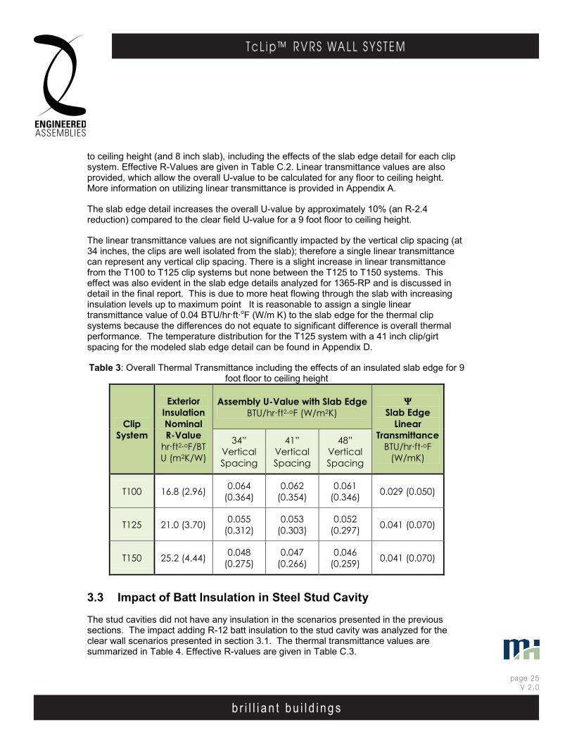
b r i l l i a n t b u i l d i n g s
page 25V 2 .0
T c L i p ™ R V R S WA L L S Y S T E M
b r i l l i a n t b u i l d i n g s
E . A . I . T h E r m A l C l I p r . V. r . S . WA l l S y S T E mEngineered Assembl ies Inc .6535 M i l l c reek D r i ve , Un i t 75M iss i ssauga , On ta r i o , Canada L5N 2M2
T 905 .816 .2218F 905 .816 .9761
E i n fo@eng inee redassemb l i es .comW Eng inee redAssemb l i es .com
page 2403DEC13
b r i l l i a n t b u i l d i n g s
E . A . I . T h E r m A l C l I p r . V. r . S . WA l l S y S T E mEngineered Assembl ies Inc .6535 M i l l c reek D r i ve , Un i t 75M iss i ssauga , On ta r i o , Canada L5N 2M2
T 905 .816 .2218F 905 .816 .9761
E i n fo@eng inee redassemb l i es .comW Eng inee redAssemb l i es .com
page 1506OCT13
to ceiling height (and 8 inch slab), including the effects of the slab edge detail for each clip system. Effective R-Values are given in Table C.2. Linear transmittance values are also provided, which allow the overall U-value to be calculated for any floor to ceiling height. More information on utilizing linear transmittance is provided in Appendix A.
The slab edge detail increases the overall U-value by approximately 10% (an R-2.4 reduction) compared to the clear field U-value for a 9 foot floor to ceiling height.
The linear transmittance values are not significantly impacted by the vertical clip spacing (at 34 inches, the clips are well isolated from the slab); therefore a single linear transmittance can represent any vertical clip spacing. There is a slight increase in linear transmittance from the T100 to T125 clip systems but none between the T125 to T150 systems. This effect was also evident in the slab edge details analyzed for 1365-RP and is discussed in detail in the final report. This is due to more heat flowing through the slab with increasing insulation levels up to maximum point It is reasonable to assign a single linear transmittance value of 0.04 BTU/hr·ft·oF (W/m K) to the slab edge for the thermal clip systems because the differences do not equate to significant difference is overall thermal performance. The temperature distribution for the T125 system with a 41 inch clip/girt spacing for the modeled slab edge detail can be found in Appendix D.
Table 3: Overall Thermal Transmittance including the effects of an insulated slab edge for 9 foot floor to ceiling height
Clip System
Exterior Insulation Nominal R-Value
hr·ft2·oF/BTU (m2K/W)
Assembly U-Value with Slab Edge BTU/hr·ft2·oF (W/m2K)
ΨΨΨΨ Slab Edge
Linear Transmittance
BTU/hr·ft·oF (W/mK)
34” Vertical Spacing
41” Vertical Spacing
48” Vertical Spacing
T100 16.8 (2.96) 0.064 (0.364)
0.062 (0.354)
0.061 (0.346) 0.029 (0.050)
T125 21.0 (3.70) 0.055 (0.312)
0.053 (0.303)
0.052 (0.297) 0.041 (0.070)
T150 25.2 (4.44) 0.048 (0.275)
0.047 (0.266)
0.046 (0.259) 0.041 (0.070)
3.3 Impact of Batt Insulation in Steel Stud Cavity
The stud cavities did not have any insulation in the scenarios presented in the previous sections. The impact adding R-12 batt insulation to the stud cavity was analyzed for the clear wall scenarios presented in section 3.1. The thermal transmittance values are summarized in Table 4. Effective R-values are given in Table C.3.
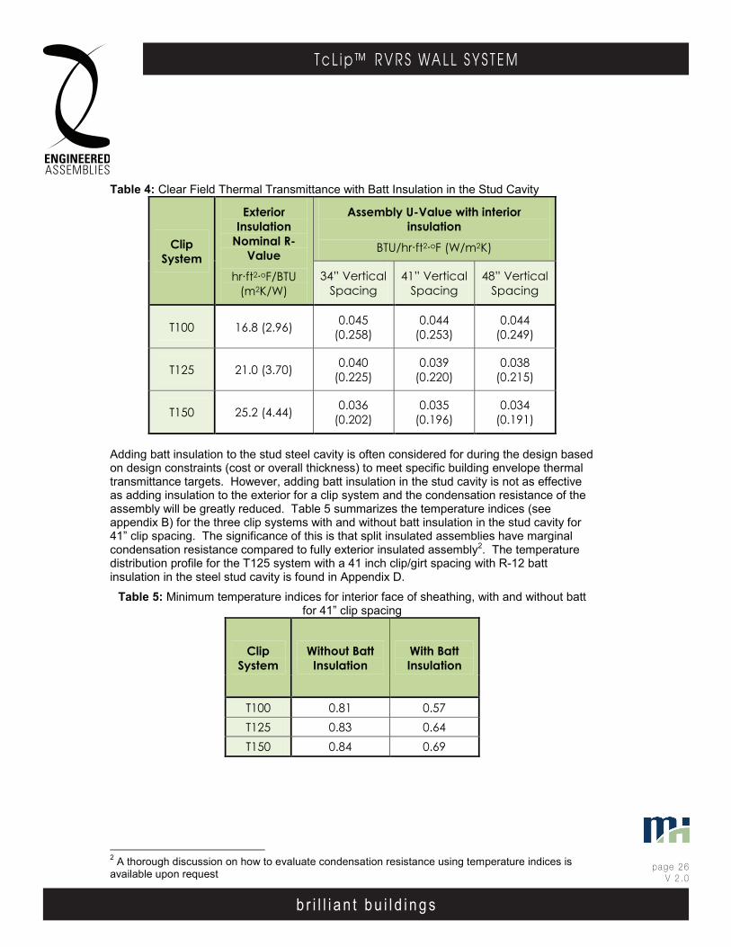
b r i l l i a n t b u i l d i n g s
page 26V 2 .0
T c L i p ™ R V R S WA L L S Y S T E M
b r i l l i a n t b u i l d i n g s
E . A . I . T h E r m A l C l I p r . V. r . S . WA l l S y S T E mEngineered Assembl ies Inc .6535 M i l l c reek D r i ve , Un i t 75M iss i ssauga , On ta r i o , Canada L5N 2M2
T 905 .816 .2218F 905 .816 .9761
E i n fo@eng inee redassemb l i es .comW Eng inee redAssemb l i es .com
page 2503DEC13
b r i l l i a n t b u i l d i n g s
E . A . I . T h E r m A l C l I p r . V. r . S . WA l l S y S T E mEngineered Assembl ies Inc .6535 M i l l c reek D r i ve , Un i t 75M iss i ssauga , On ta r i o , Canada L5N 2M2
T 905 .816 .2218F 905 .816 .9761
E i n fo@eng inee redassemb l i es .comW Eng inee redAssemb l i es .com
page 1606OCT13
Table 4: Clear Field Thermal Transmittance with Batt Insulation in the Stud Cavity
Clip System
Exterior Insulation
Nominal R-Value
hr·ft2·oF/BTU (m2K/W)
Assembly U-Value with interior insulation
BTU/hr·ft2·oF (W/m2K)
34” Vertical Spacing
41” Vertical Spacing
48” Vertical Spacing
T100 16.8 (2.96) 0.045 (0.258)
0.044 (0.253)
0.044 (0.249)
T125 21.0 (3.70) 0.040 (0.225)
0.039 (0.220)
0.038 (0.215)
T150 25.2 (4.44) 0.036 (0.202)
0.035 (0.196)
0.034 (0.191)
Adding batt insulation to the stud steel cavity is often considered for during the design based on design constraints (cost or overall thickness) to meet specific building envelope thermal transmittance targets. However, adding batt insulation in the stud cavity is not as effective as adding insulation to the exterior for a clip system and the condensation resistance of the assembly will be greatly reduced. Table 5 summarizes the temperature indices (see appendix B) for the three clip systems with and without batt insulation in the stud cavity for 41” clip spacing. The significance of this is that split insulated assemblies have marginal condensation resistance compared to fully exterior insulated assembly2. The temperature distribution profile for the T125 system with a 41 inch clip/girt spacing with R-12 batt insulation in the steel stud cavity is found in Appendix D.
Table 5: Minimum temperature indices for interior face of sheathing, with and without batt for 41” clip spacing
Clip System
Without Batt Insulation
With Batt Insulation
T100 0.81 0.57 T125 0.83 0.64 T150 0.84 0.69
2 A thorough discussion on how to evaluate condensation resistance using temperature indices is available upon request

b r i l l i a n t b u i l d i n g s
page 27V 2 .0
T c L i p ™ R V R S WA L L S Y S T E M
b r i l l i a n t b u i l d i n g s
E . A . I . T h E r m A l C l I p r . V. r . S . WA l l S y S T E mEngineered Assembl ies Inc .6535 M i l l c reek D r i ve , Un i t 75M iss i ssauga , On ta r i o , Canada L5N 2M2
T 905 .816 .2218F 905 .816 .9761
E i n fo@eng inee redassemb l i es .comW Eng inee redAssemb l i es .com
page 2603DEC13
b r i l l i a n t b u i l d i n g s
E . A . I . T h E r m A l C l I p r . V. r . S . WA l l S y S T E mEngineered Assembl ies Inc .6535 M i l l c reek D r i ve , Un i t 75M iss i ssauga , On ta r i o , Canada L5N 2M2
T 905 .816 .2218F 905 .816 .9761
E i n fo@eng inee redassemb l i es .comW Eng inee redAssemb l i es .com
page 1706OCT13
4. SENSITIVITY ANALYSIS A sensitivity analysis of the modeled systems was performed to allow designers to interpolate the thermal performance values for others insulation levels and clip spacing.
4.1 Insulation Type
The base modeling assumed semi-rigid insulation (R 4.2 / inch) for the exterior insulation. Other conductivities were evaluated to allow the thermal transmittance values for the thermal clip system to be utilized for other types of insulation. In order to characterize the range of exterior insulation values, the modeled assemblies in section 3.1 were re-calculated using a low end of R-3.5 per inch (RSI-0.62 per inch) to a high end of R-6.5 per inch (RSI-1.14 per inch). Figure 1 shows the graphical results for effective assembly R-Value for a clip spacing of 41 inch for the varying R-per inch materials. The case of continuous exterior insulation as assumed in energy standard ASHRAE 90.1-2007 is also graphed as a reference.
Figure 1: Effective Assembly R-Value vs Nominal Insulation R-Value for a variety of insulation materials for 41 in clip spacing
The results show that the thickness of the insulation (and length of the clip) for a given nominal thermal resistance is largely independent of the effective R-value. Therefore, the results can be characterized by the R-value of the exterior insulation and can be applied to any material. The results from Table 2 can be re-arranged and additional R-values can be interpolated with the results from the sensitivity analysis. The U-value results are presented in Table 6. Effective R-Values are given in Table C.4.
0.0
5.0
10.0
15.0
20.0
25.0
30.0
35.0
40.0
45.0
0.0 10.0 20.0 30.0 40.0
Effe
ctiv
e As
sem
bly
R-Va
lue
(hr∙f
t2 ∙o F/B
TU)
Nominal R-Value of Exterior Insulation (hr∙ft2∙oF/BTU)
R-3.5 per inch R- 4.2 per inchR- 6.5 per inch Continuous Insulation
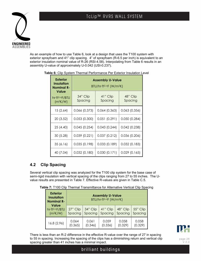
b r i l l i a n t b u i l d i n g s
page 28V 2 .0
T c L i p ™ R V R S WA L L S Y S T E M
b r i l l i a n t b u i l d i n g s
E . A . I . T h E r m A l C l I p r . V. r . S . WA l l S y S T E mEngineered Assembl ies Inc .6535 M i l l c reek D r i ve , Un i t 75M iss i ssauga , On ta r i o , Canada L5N 2M2
T 905 .816 .2218F 905 .816 .9761
E i n fo@eng inee redassemb l i es .comW Eng inee redAssemb l i es .com
page 2703DEC13
b r i l l i a n t b u i l d i n g s
E . A . I . T h E r m A l C l I p r . V. r . S . WA l l S y S T E mEngineered Assembl ies Inc .6535 M i l l c reek D r i ve , Un i t 75M iss i ssauga , On ta r i o , Canada L5N 2M2
T 905 .816 .2218F 905 .816 .9761
E i n fo@eng inee redassemb l i es .comW Eng inee redAssemb l i es .com
page 1806OCT13
As an example of how to use Table 6, look at a design that uses the T100 system with exterior sprayfoam and 41” clip spacing. 4” of sprayfoam (R-6.5 per inch) is equivalent to an exterior insulation nominal value of R-26 (RSI-4.58). Interpolating from Table 6 results in an assembly U-value of approximately U-0.042 (USI-0.237).
Table 6: Clip System Thermal Performance Per Exterior Insulation Level
Exterior Insulation
Nominal R-Value
hr·ft2·oF/BTU (m2K/W)
Assembly U-Value
BTU/hr·ft2·oF (W/m2K)
34” Clip Spacing
41” Clip Spacing
48” Clip Spacing
15 (2.64) 0.066 (0.373) 0.064 (0.363) 0.063 (0.356)
20 (3.52) 0.053 (0.300) 0.051 (0.291) 0.050 (0.284)
25 (4.40) 0.045 (0.254) 0.043 (0.244) 0.042 (0.238)
30 (5.28) 0.039 (0.221) 0.037 (0.212) 0.036 (0.206)
35 (6.16) 0.035 (0.198) 0.033 (0.189) 0.032 (0.183)
40 (7.04) 0.032 (0.180) 0.030 (0.171) 0.029 (0.165)
4.2 Clip Spacing
Several vertical clip spacing was analyzed for the T100 clip system for the base case of semi-rigid insulation with vertical spacing of the clips ranging from 27 to 55 inches. The U-value results are presented in Table 7. Effective R-values are given in Table C.5.
Table 7: T100 Clip Thermal Transmittance for Alternative Vertical Clip Spacing
Exterior Insulation
Nominal R-Value
hr·ft2·oF/BTU (m2K/W)
Assembly U-Value BTU/hr·ft2·oF (W/m2K)
27” Clip Spacing
34” Clip Spacing
41” Clip Spacing
48” Clip Spacing
55” Clip Spacing
16.8 (2.96) 0.064 (0.365)
0.061 (0.346)
0.059 (0.336)
0.058 (0.329)
0.058 (0.329)
There is less than an R-2 difference in the effective R-value over the range of 27 in spacing to 55 in spacing. Increasing the spacing of the clips has a diminishing return and vertical clip spacing greater than 41 inches has a minimal impact.
b r i l l i a n t b u i l d i n g s
page 29V 2 .0
T c L i p ™ R V R S WA L L S Y S T E M
b r i l l i a n t b u i l d i n g s
E . A . I . T h E r m A l C l I p r . V. r . S . WA l l S y S T E mEngineered Assembl ies Inc .6535 M i l l c reek D r i ve , Un i t 75M iss i ssauga , On ta r i o , Canada L5N 2M2
T 905 .816 .2218F 905 .816 .9761
E i n fo@eng inee redassemb l i es .comW Eng inee redAssemb l i es .com
page 2803DEC13
b r i l l i a n t b u i l d i n g s
E . A . I . T h E r m A l C l I p r . V. r . S . WA l l S y S T E mEngineered Assembl ies Inc .6535 M i l l c reek D r i ve , Un i t 75M iss i ssauga , On ta r i o , Canada L5N 2M2
T 905 .816 .2218F 905 .816 .9761
E i n fo@eng inee redassemb l i es .comW Eng inee redAssemb l i es .com
page 1906OCT13
5. BUILDING ENVELOPE REQUIREMENTS IN CANADA
For most provinces, the National Building Code of Canada is used as the basis for their respective building codes, with changes and implementations tailored for each province. For single family or low-rise (Part 9) buildings, provincial codes typically have their requirements for building envelope minimum insulation levels, however, for commercial or mid and high rise construction (non Part 9), many codes reference existing standards from national and international organizations. In regards to the building envelope, the most commonly referenced standards across Canada are ASHRAE 90.1 “Energy Standard for Buildings Except Low-Rise Residential Buildings” and the Model National Energy Code for Buildings (MNECB) 1997. The National Energy Code for Buildings (NECB) 2011 has recently been issued to replace MNECB 1997.
While these two standards differ in their specific requirements, they both employ three options for showing compliance: Prescriptive, Trade-off and Performance.
The prescriptive path awards compliance for explicitly meeting all provisions of the code relevant to the project in question. For the building envelope, assemblies must be lower than a given maximum thermal transmittance U-value or must meet or exceed insulation values in a prescribed assembly. These requirements can be based on climate region, building type/principal heating source and framing type, depending on the standard. The prescriptive path is widely used as it is fairly straight forward and building components need only be assessed individually. However, some of the prescriptive requirements may be difficult to achieve due to design trends. For example, in ASHRAE 90.1-2007, the prescriptive path requires a glazing to wall ratio of less than 40%. If these prescriptive requirements cannot be met, then another compliance path must be used.
The trade-off path allows for projects to trade-off the performance of building envelope components (i.e. roofs, walls, and windows) when the prescriptive requirements are not met for each and every item. With this approach, the performance of some envelope components may be lower than the prescribed values in the standard as long as other components exceed the requirements so that the overall building envelope is deemed to be equal or better than the standard. For example, this allows for low thermally performing walls if the roof sufficiently compensates above its prescriptive values. The trade-off method allows for some flexibility with the prescriptive values. This approach can be demonstrated using either specific calculations (provided in the standards) or through computer software that is typically provided by the authors of the standard.
The performance path requires an evaluation of the annual energy use of the whole building. This must be done using computer simulation, where the proposed building and its systems are modeled and compared to a compliance building. The compliance building contains the same shape, size, occupancy and scheduling of proposed building, but all of its systems and individual components meet the minimum requirements of the standard. For example, for the compliance building, the thermal performance of the walls of the compliance building must match the prescriptive U-values of the standard. The proposed design is acceptable if the annual energy use is less than or equal to that of the compliance building. Energy certification programs, such as Leadership in Energy and Environmental Design (LEED), have used MNECB and ASHRAE performance paths as this can allow for
b r i l l i a n t b u i l d i n g s
page 30V 2 .0
T c L i p ™ R V R S WA L L S Y S T E M
b r i l l i a n t b u i l d i n g s
E . A . I . T h E r m A l C l I p r . V. r . S . WA l l S y S T E mEngineered Assembl ies Inc .6535 M i l l c reek D r i ve , Un i t 75M iss i ssauga , On ta r i o , Canada L5N 2M2
T 905 .816 .2218F 905 .816 .9761
E i n fo@eng inee redassemb l i es .comW Eng inee redAssemb l i es .com
page 2903DEC13
b r i l l i a n t b u i l d i n g s
E . A . I . T h E r m A l C l I p r . V. r . S . WA l l S y S T E mEngineered Assembl ies Inc .6535 M i l l c reek D r i ve , Un i t 75M iss i ssauga , On ta r i o , Canada L5N 2M2
T 905 .816 .2218F 905 .816 .9761
E i n fo@eng inee redassemb l i es .comW Eng inee redAssemb l i es .com
page 2006OCT13
much greater flexibility in design. The performance path takes into account other variables such as building orientation, higher efficiency HVAC systems and lighting controls, which would not give any benefit with the other two compliance paths. Each standard gives requirements that specify what can and cannot be included with the energy model and which energy modeling programs can be used.
The Ontario Building Code (OBC) contains a supplementary standard SB-10 to deal with energy in non-Part 9 buildings. As of January 1st, 2012, SB-10 incorporates ASHRAE 90.1-2010; however the prescriptive path is modified by including the values from ASHRAE 189.1 “Standard for the Design of High Performance, Green Buildings” for envelope requirements. For the performance path, compliance can be achieved by modeling energy savings 5% better than ASHRAE 90.1-2010, 25% better than MNECB 1997 or meeting ASHRAE 90.1-2010 modified by ASHRAE 189.1.
Currently, both the Alberta Building Code (ABC) and the Quebec Construction Code (CCQ) only have prescriptive values for minimum insulation levels in Part 9 buildings; however it does not contain any requirements for non Part 9 buildings. It is our understanding that both provinces are considering adopting NECB 2011 in order to assist in meeting their energy efficiency targets.
In British Columbia there are two governing documents. The majority of the province falls under the British Columbia Building Code (BCBC), while Vancouver follows the Vancouver Building Bylaw (VBBL). For non-Part 9 buildings, BCBC references ASHRAE 90.1-2004, while VBBL references the more recent ASHRAE 90.1-2007. The 90.1-2007 requirements are more stringent than 90.1-2004 (lower allowable glazing ratios, lower U-values, higher efficiency systems etc.), however the approach remains the same. The BCBC has recently adopted new energy efficiency requirements that allow a choice of compliance to either the ASHRAE 90.1-2010 or the NECB 2011. The effective date is December 20, 2013. VBBL will also likely update to at least the requirements in BCBC soon.
Table 8 summarizes the prescriptive wall assembly requirements from ASHRAE 90.1 2004, 2007 and 2010 for steel framed buildings along with wall assembly requirements from NECB 2011. Canadian climate zones in both ASHRAE and NECB are divided by heating degree days (HDD). NECB divides zones every 1000 HDD, however ASHRAE groups climate zones by 1000 or 2000 HDD. Both zone types are included.
ASHRAE 90.1 tends to be updated every 3 years. From this chart, it can be seen that the trend from 2004-2007 was to decrease the maximum U-value. The decrease in U-value appears to be based on increasing the amount of continuous exterior insulation. Adjusting the building envelope prescriptive requirements does not happen with every cycle (2007-2010 did not see further decreases to U-value); however ASHRAE 90.1 may choose to do so in the future as other standards, such as NECB 2011, already have more stringent prescriptive requirements.
Moving forward, to achieve realistic thermal performance goals, standards will need to begin to account for thermal bridging in details. Currently, many codes in Canada offer exemptions for the thermal effects of details (such as slab edges) or their inclusion is often left to interpretation by designers. For example, in the ASHRAE 90.1 performance path, slab edges are typically ignored as long as they are less than 5% of the wall area. Depending on the detail, these thermal bridges can have a major impact on the thermal performance of the building envelope.
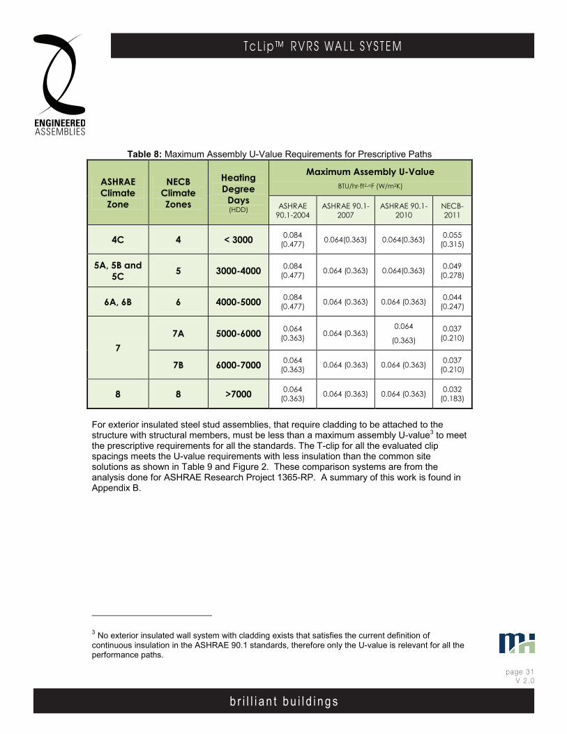
b r i l l i a n t b u i l d i n g s
page 31V 2 .0
T c L i p ™ R V R S WA L L S Y S T E M
b r i l l i a n t b u i l d i n g s
E . A . I . T h E r m A l C l I p r . V. r . S . WA l l S y S T E mEngineered Assembl ies Inc .6535 M i l l c reek D r i ve , Un i t 75M iss i ssauga , On ta r i o , Canada L5N 2M2
T 905 .816 .2218F 905 .816 .9761
E i n fo@eng inee redassemb l i es .comW Eng inee redAssemb l i es .com
page 3003DEC13
b r i l l i a n t b u i l d i n g s
E . A . I . T h E r m A l C l I p r . V. r . S . WA l l S y S T E mEngineered Assembl ies Inc .6535 M i l l c reek D r i ve , Un i t 75M iss i ssauga , On ta r i o , Canada L5N 2M2
T 905 .816 .2218F 905 .816 .9761
E i n fo@eng inee redassemb l i es .comW Eng inee redAssemb l i es .com
page 2106OCT13
Table 8: Maximum Assembly U-Value Requirements for Prescriptive Paths
ASHRAE Climate
Zone
NECB Climate Zones
Heating Degree
Days (HDD)
Maximum Assembly U-Value BTU/hr∙ft2∙oF (W/m2K)
ASHRAE 90.1-2004
ASHRAE 90.1-2007
ASHRAE 90.1-2010
NECB-2011
4C 4 < 3000 0.084 (0.477) 0.064(0.363) 0.064(0.363) 0.055
(0.315)
5A, 5B and 5C 5 3000-4000 0.084
(0.477) 0.064 (0.363) 0.064(0.363) 0.049 (0.278)
6A, 6B 6 4000-5000 0.084 (0.477) 0.064 (0.363) 0.064 (0.363) 0.044
(0.247)
7 7A 5000-6000 0.064
(0.363) 0.064 (0.363) 0.064
(0.363) 0.037
(0.210)
7B 6000-7000 0.064 (0.363) 0.064 (0.363) 0.064 (0.363) 0.037
(0.210)
8 8 >7000 0.064 (0.363) 0.064 (0.363) 0.064 (0.363) 0.032
(0.183)
For exterior insulated steel stud assemblies, that require cladding to be attached to the structure with structural members, must be less than a maximum assembly U-value3 to meet the prescriptive requirements for all the standards. The T-clip for all the evaluated clip spacings meets the U-value requirements with less insulation than the common site solutions as shown in Table 9 and Figure 2. These comparison systems are from the analysis done for ASHRAE Research Project 1365-RP. A summary of this work is found in Appendix B.
3 No exterior insulated wall system with cladding exists that satisfies the current definition of continuous insulation in the ASHRAE 90.1 standards, therefore only the U-value is relevant for all the performance paths.
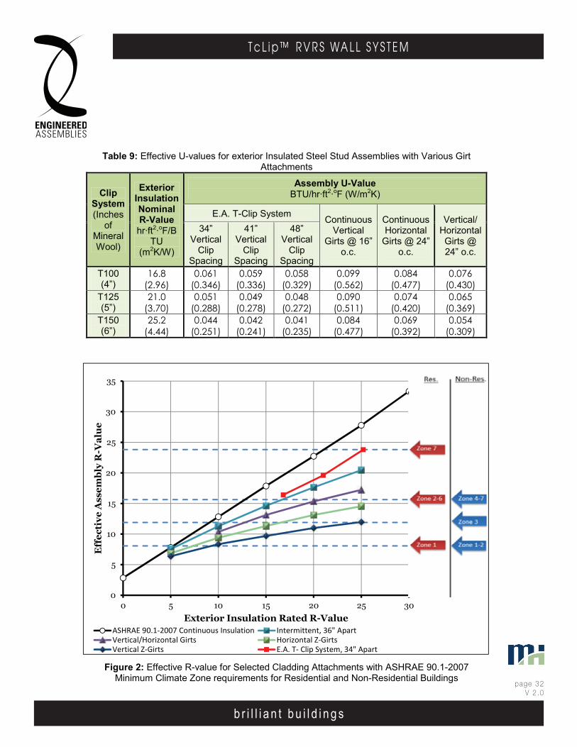
b r i l l i a n t b u i l d i n g s
page 32V 2 .0
T c L i p ™ R V R S WA L L S Y S T E M
b r i l l i a n t b u i l d i n g s
E . A . I . T h E r m A l C l I p r . V. r . S . WA l l S y S T E mEngineered Assembl ies Inc .6535 M i l l c reek D r i ve , Un i t 75M iss i ssauga , On ta r i o , Canada L5N 2M2
T 905 .816 .2218F 905 .816 .9761
E i n fo@eng inee redassemb l i es .comW Eng inee redAssemb l i es .com
page 3103DEC13
b r i l l i a n t b u i l d i n g s
E . A . I . T h E r m A l C l I p r . V. r . S . WA l l S y S T E mEngineered Assembl ies Inc .6535 M i l l c reek D r i ve , Un i t 75M iss i ssauga , On ta r i o , Canada L5N 2M2
T 905 .816 .2218F 905 .816 .9761
E i n fo@eng inee redassemb l i es .comW Eng inee redAssemb l i es .com
page 2206OCT13
0
5
10
15
20
25
30
35
0 5 10 15 20 25 30
Eff
ecti
ve A
ssem
bly
R-V
alu
e
Exterior Insulation Rated R-Value ASHRAE 90.1-2007 Continuous Insulation Intermittent, 36" ApartVertical/Horizontal Girts Horizontal Z-GirtsVertical Z-Girts E.A. T- Clip System, 34" Apart
Table 9: Effective U-values for exterior Insulated Steel Stud Assemblies with Various Girt Attachments
Clip System (Inches
of Mineral Wool)
Exterior Insulation Nominal R-Value hr·ft2·oF/B
TU (m2K/W)
Assembly U-Value BTU/hr·ft2·oF (W/m2K)
E.A. T-Clip System Continuous Vertical
Girts @ 16” o.c.
Continuous Horizontal
Girts @ 24” o.c.
Vertical/ Horizontal Girts @ 24” o.c.
34” Vertical
Clip Spacing
41” Vertical
Clip Spacing
48” Vertical
Clip Spacing
T100 (4”)
16.8 (2.96)
0.061 (0.346)
0.059 (0.336)
0.058 (0.329)
0.099 (0.562)
0.084 (0.477)
0.076 (0.430)
T125 (5”)
21.0 (3.70)
0.051 (0.288)
0.049 (0.278)
0.048 (0.272)
0.090 (0.511)
0.074 (0.420)
0.065 (0.369)
T150 (6”)
25.2 (4.44)
0.044 (0.251)
0.042 (0.241)
0.041 (0.235)
0.084 (0.477)
0.069 (0.392)
0.054 (0.309)
Figure 2: Effective R-value for Selected Cladding Attachments with ASHRAE 90.1-2007 Minimum Climate Zone requirements for Residential and Non-Residential Buildings
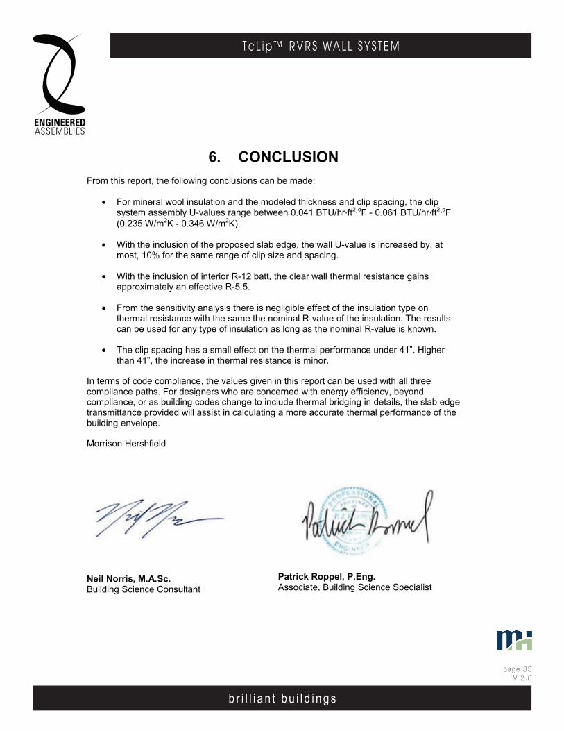
b r i l l i a n t b u i l d i n g s
page 33V 2 .0
T c L i p ™ R V R S WA L L S Y S T E M
b r i l l i a n t b u i l d i n g s
E . A . I . T h E r m A l C l I p r . V. r . S . WA l l S y S T E mEngineered Assembl ies Inc .6535 M i l l c reek D r i ve , Un i t 75M iss i ssauga , On ta r i o , Canada L5N 2M2
T 905 .816 .2218F 905 .816 .9761
E i n fo@eng inee redassemb l i es .comW Eng inee redAssemb l i es .com
page 3203DEC13
b r i l l i a n t b u i l d i n g s
E . A . I . T h E r m A l C l I p r . V. r . S . WA l l S y S T E mEngineered Assembl ies Inc .6535 M i l l c reek D r i ve , Un i t 75M iss i ssauga , On ta r i o , Canada L5N 2M2
T 905 .816 .2218F 905 .816 .9761
E i n fo@eng inee redassemb l i es .comW Eng inee redAssemb l i es .com
page 2306OCT13
6. CONCLUSION From this report, the following conclusions can be made:
• For mineral wool insulation and the modeled thickness and clip spacing, the clip system assembly U-values range between 0.041 BTU/hr∙ft2∙oF - 0.061 BTU/hr∙ft2∙oF (0.235 W/m2K - 0.346 W/m2K).
• With the inclusion of the proposed slab edge, the wall U-value is increased by, at most, 10% for the same range of clip size and spacing.
• With the inclusion of interior R-12 batt, the clear wall thermal resistance gains approximately an effective R-5.5.
• From the sensitivity analysis there is negligible effect of the insulation type on thermal resistance with the same the nominal R-value of the insulation. The results can be used for any type of insulation as long as the nominal R-value is known.
• The clip spacing has a small effect on the thermal performance under 41”. Higher than 41”, the increase in thermal resistance is minor.
In terms of code compliance, the values given in this report can be used with all three compliance paths. For designers who are concerned with energy efficiency, beyond compliance, or as building codes change to include thermal bridging in details, the slab edge transmittance provided will assist in calculating a more accurate thermal performance of the building envelope.
Morrison Hershfield
Neil Norris, M.A.Sc. Building Science Consultant
Patrick Roppel, P.Eng. Associate, Building Science Specialist
b r i l l i a n t b u i l d i n g s
page 34V 2 .0
T c L i p ™ R V R S WA L L S Y S T E M
b r i l l i a n t b u i l d i n g s
E . A . I . T h E r m A l C l I p r . V. r . S . WA l l S y S T E mEngineered Assembl ies Inc .6535 M i l l c reek D r i ve , Un i t 75M iss i ssauga , On ta r i o , Canada L5N 2M2
T 905 .816 .2218F 905 .816 .9761
E i n fo@eng inee redassemb l i es .comW Eng inee redAssemb l i es .com
page 3303DEC13
b r i l l i a n t b u i l d i n g s
E . A . I . T h E r m A l C l I p r . V. r . S . WA l l S y S T E mEngineered Assembl ies Inc .6535 M i l l c reek D r i ve , Un i t 75M iss i ssauga , On ta r i o , Canada L5N 2M2
T 905 .816 .2218F 905 .816 .9761
E i n fo@eng inee redassemb l i es .comW Eng inee redAssemb l i es .com
page 2406OCT13
APPENDIX A – CLIP SYSTEM DETAILS AND MATERIAL PROPERTIES
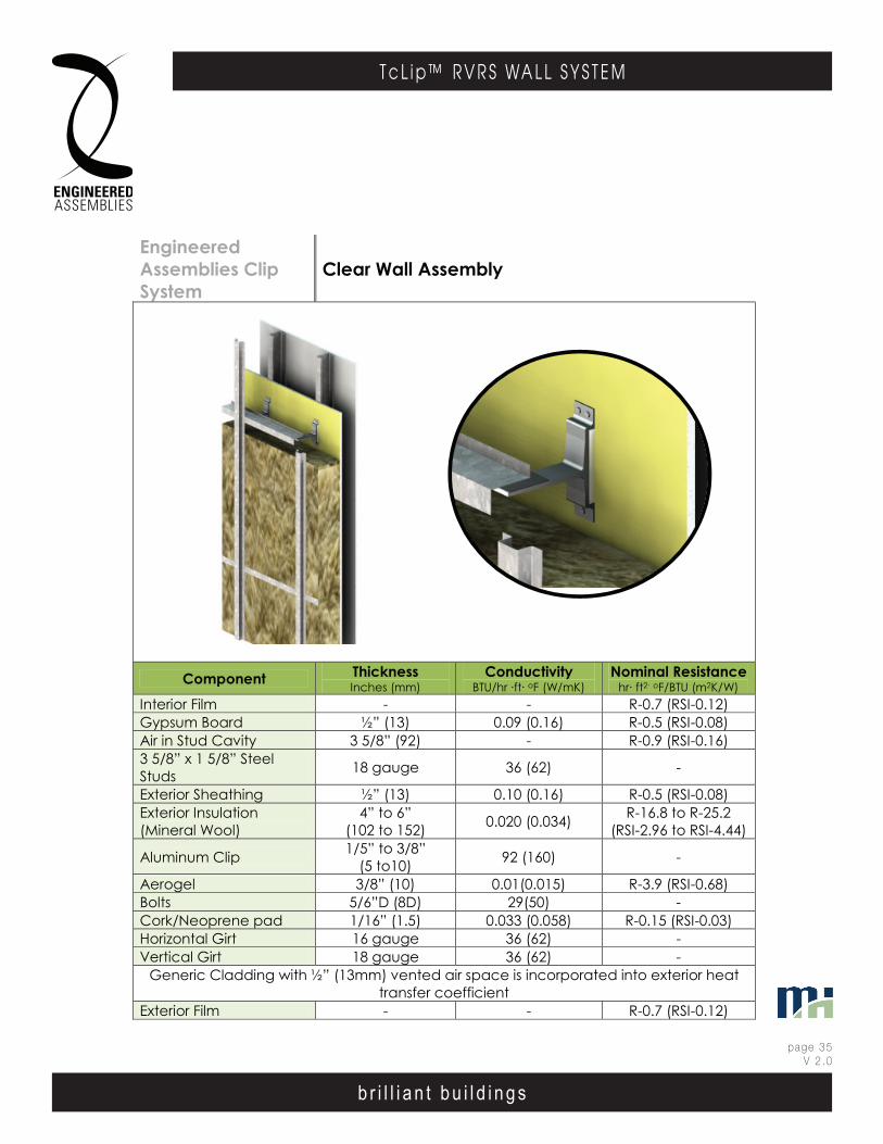
b r i l l i a n t b u i l d i n g s
page 35V 2 .0
T c L i p ™ R V R S WA L L S Y S T E M
b r i l l i a n t b u i l d i n g s
E . A . I . T h E r m A l C l I p r . V. r . S . WA l l S y S T E mEngineered Assembl ies Inc .6535 M i l l c reek D r i ve , Un i t 75M iss i ssauga , On ta r i o , Canada L5N 2M2
T 905 .816 .2218F 905 .816 .9761
E i n fo@eng inee redassemb l i es .comW Eng inee redAssemb l i es .com
page 3403DEC13
b r i l l i a n t b u i l d i n g s
E . A . I . T h E r m A l C l I p r . V. r . S . WA l l S y S T E mEngineered Assembl ies Inc .6535 M i l l c reek D r i ve , Un i t 75M iss i ssauga , On ta r i o , Canada L5N 2M2
T 905 .816 .2218F 905 .816 .9761
E i n fo@eng inee redassemb l i es .comW Eng inee redAssemb l i es .com
page 2506OCT13
Engineered Assemblies Clip System
Clear Wall Assembly
Component Thickness Inches (mm)
Conductivity BTU/hr ·ft· oF (W/mK)
Nominal Resistance hr· ft2· oF/BTU (m2K/W)
Interior Film - - R-0.7 (RSI-0.12) Gypsum Board ½” (13) 0.09 (0.16) R-0.5 (RSI-0.08) Air in Stud Cavity 3 5/8” (92) - R-0.9 (RSI-0.16) 3 5/8” x 1 5/8” Steel Studs 18 gauge 36 (62) -
Exterior Sheathing ½” (13) 0.10 (0.16) R-0.5 (RSI-0.08) Exterior Insulation (Mineral Wool)
4” to 6” (102 to 152) 0.020 (0.034) R-16.8 to R-25.2
(RSI-2.96 to RSI-4.44)
Aluminum Clip 1/5” to 3/8” (5 to10) 92 (160) -
Aerogel 3/8” (10) 0.01(0.015) R-3.9 (RSI-0.68) Bolts 5/6”D (8D) 29(50) - Cork/Neoprene pad 1/16” (1.5) 0.033 (0.058) R-0.15 (RSI-0.03) Horizontal Girt 16 gauge 36 (62) - Vertical Girt 18 gauge 36 (62) -
Generic Cladding with ½” (13mm) vented air space is incorporated into exterior heat transfer coefficient
Exterior Film - - R-0.7 (RSI-0.12)
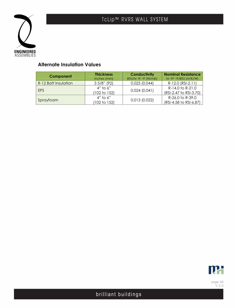
b r i l l i a n t b u i l d i n g s
page 36V 2 .0
T c L i p ™ R V R S WA L L S Y S T E M
b r i l l i a n t b u i l d i n g s
E . A . I . T h E r m A l C l I p r . V. r . S . WA l l S y S T E mEngineered Assembl ies Inc .6535 M i l l c reek D r i ve , Un i t 75M iss i ssauga , On ta r i o , Canada L5N 2M2
T 905 .816 .2218F 905 .816 .9761
E i n fo@eng inee redassemb l i es .comW Eng inee redAssemb l i es .com
page 3503DEC13
b r i l l i a n t b u i l d i n g s
E . A . I . T h E r m A l C l I p r . V. r . S . WA l l S y S T E mEngineered Assembl ies Inc .6535 M i l l c reek D r i ve , Un i t 75M iss i ssauga , On ta r i o , Canada L5N 2M2
T 905 .816 .2218F 905 .816 .9761
E i n fo@eng inee redassemb l i es .comW Eng inee redAssemb l i es .com
page 2606OCT13
Alternate Insulation Values
Component Thickness Inches (mm)
Conductivity BTU/hr ·ft· oF (W/mK)
Nominal Resistance hr· ft2· oF/BTU (m2K/W)
R-12 Batt Insulation 3 5/8” (92) 0.025 (0.044) R-12.0 (RSI-2.11)
EPS 4” to 6” (102 to 152) 0.024 (0.041) R-14.0 to R-21.0
(RSI-2.47 to RSI-3.70)
Sprayfoam 4” to 6” (102 to 152) 0.013 (0.022) R-26.0 to R-39.0
(RSI-4.58 to RSI-6.87)
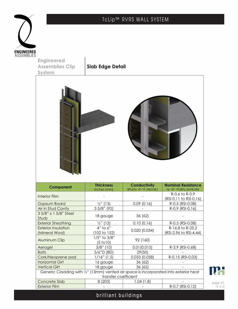
b r i l l i a n t b u i l d i n g s
page 37V 2 .0
T c L i p ™ R V R S WA L L S Y S T E M
b r i l l i a n t b u i l d i n g s
E . A . I . T h E r m A l C l I p r . V. r . S . WA l l S y S T E mEngineered Assembl ies Inc .6535 M i l l c reek D r i ve , Un i t 75M iss i ssauga , On ta r i o , Canada L5N 2M2
T 905 .816 .2218F 905 .816 .9761
E i n fo@eng inee redassemb l i es .comW Eng inee redAssemb l i es .com
page 3603DEC13
b r i l l i a n t b u i l d i n g s
E . A . I . T h E r m A l C l I p r . V. r . S . WA l l S y S T E mEngineered Assembl ies Inc .6535 M i l l c reek D r i ve , Un i t 75M iss i ssauga , On ta r i o , Canada L5N 2M2
T 905 .816 .2218F 905 .816 .9761
E i n fo@eng inee redassemb l i es .comW Eng inee redAssemb l i es .com
page 2706OCT13
Engineered Assemblies Clip System
Slab Edge Detail
Component Thickness Inches (mm)
Conductivity BTU/hr ·ft· oF (W/mK)
Nominal Resistance hr· ft2· oF/BTU (m2K/W)
Interior Film - - R-0.6 to R-0.9 (RSI-0.11 to RSI-0.16)
Gypsum Board ½” (13) 0.09 (0.16) R-0.5 (RSI-0.08) Air in Stud Cavity 3 5/8” (92) - R-0.9 (RSI-0.16) 3 5/8” x 1 5/8” Steel Studs 18 gauge 36 (62) -
Exterior Sheathing ½” (13) 0.10 (0.16) R-0.5 (RSI-0.08) Exterior Insulation (Mineral Wool)
4” to 6” (102 to 152) 0.020 (0.034) R-16.8 to R-25.2
(RSI-2.96 to RSI-4.44)
Aluminum Clip 1/5” to 3/8” (5 to10) 92 (160) -
Aerogel 3/8” (10) 0.01(0.015) R-3.9 (RSI-0.68) Bolts 5/6”D (8D) 29(50) - Cork/Neoprene pad 1/16” (1.5) 0.033 (0.058) R-0.15 (RSI-0.03) Horizontal Girt 16 gauge 36 (62) - Vertical Girt 18 gauge 36 (62) -
Generic Cladding with ½” (13mm) vented air space is incorporated into exterior heat transfer coefficient
Concrete Slab 8 (203) 1.04 (1.8) - Exterior Film - - R-0.7 (RSI-0.12)

b r i l l i a n t b u i l d i n g s
page 38V 2 .0
T c L i p ™ R V R S WA L L S Y S T E M
b r i l l i a n t b u i l d i n g s
E . A . I . T h E r m A l C l I p r . V. r . S . WA l l S y S T E mEngineered Assembl ies Inc .6535 M i l l c reek D r i ve , Un i t 75M iss i ssauga , On ta r i o , Canada L5N 2M2
T 905 .816 .2218F 905 .816 .9761
E i n fo@eng inee redassemb l i es .comW Eng inee redAssemb l i es .com
page 3703DEC13
b r i l l i a n t b u i l d i n g s
E . A . I . T h E r m A l C l I p r . V. r . S . WA l l S y S T E mEngineered Assembl ies Inc .6535 M i l l c reek D r i ve , Un i t 75M iss i ssauga , On ta r i o , Canada L5N 2M2
T 905 .816 .2218F 905 .816 .9761
E i n fo@eng inee redassemb l i es .comW Eng inee redAssemb l i es .com
page 2806OCT13
T100
ADjUsTMENT rANgE +5 -15
T100

b r i l l i a n t b u i l d i n g s
page 39V 2 .0
T c L i p ™ R V R S WA L L S Y S T E M
b r i l l i a n t b u i l d i n g s
E . A . I . T h E r m A l C l I p r . V. r . S . WA l l S y S T E mEngineered Assembl ies Inc .6535 M i l l c reek D r i ve , Un i t 75M iss i ssauga , On ta r i o , Canada L5N 2M2
T 905 .816 .2218F 905 .816 .9761
E i n fo@eng inee redassemb l i es .comW Eng inee redAssemb l i es .com
page 3803DEC13
b r i l l i a n t b u i l d i n g s
E . A . I . T h E r m A l C l I p r . V. r . S . WA l l S y S T E mEngineered Assembl ies Inc .6535 M i l l c reek D r i ve , Un i t 75M iss i ssauga , On ta r i o , Canada L5N 2M2
T 905 .816 .2218F 905 .816 .9761
E i n fo@eng inee redassemb l i es .comW Eng inee redAssemb l i es .com
page 2906OCT13
T125
ADjUsTMENT rANgE +5 -15
T125

b r i l l i a n t b u i l d i n g s
page 40V 2 .0
T c L i p ™ R V R S WA L L S Y S T E M
b r i l l i a n t b u i l d i n g s
E . A . I . T h E r m A l C l I p r . V. r . S . WA l l S y S T E mEngineered Assembl ies Inc .6535 M i l l c reek D r i ve , Un i t 75M iss i ssauga , On ta r i o , Canada L5N 2M2
T 905 .816 .2218F 905 .816 .9761
E i n fo@eng inee redassemb l i es .comW Eng inee redAssemb l i es .com
page 3903DEC13
b r i l l i a n t b u i l d i n g s
E . A . I . T h E r m A l C l I p r . V. r . S . WA l l S y S T E mEngineered Assembl ies Inc .6535 M i l l c reek D r i ve , Un i t 75M iss i ssauga , On ta r i o , Canada L5N 2M2
T 905 .816 .2218F 905 .816 .9761
E i n fo@eng inee redassemb l i es .comW Eng inee redAssemb l i es .com
page 3006OCT13
T150
ADjUsTMENT rANgE +5 -15
T150
b r i l l i a n t b u i l d i n g s
page 41V 2 .0
T c L i p ™ R V R S WA L L S Y S T E M
b r i l l i a n t b u i l d i n g s
E . A . I . T h E r m A l C l I p r . V. r . S . WA l l S y S T E mEngineered Assembl ies Inc .6535 M i l l c reek D r i ve , Un i t 75M iss i ssauga , On ta r i o , Canada L5N 2M2
T 905 .816 .2218F 905 .816 .9761
E i n fo@eng inee redassemb l i es .comW Eng inee redAssemb l i es .com
page 4003DEC13
b r i l l i a n t b u i l d i n g s
E . A . I . T h E r m A l C l I p r . V. r . S . WA l l S y S T E mEngineered Assembl ies Inc .6535 M i l l c reek D r i ve , Un i t 75M iss i ssauga , On ta r i o , Canada L5N 2M2
T 905 .816 .2218F 905 .816 .9761
E i n fo@eng inee redassemb l i es .comW Eng inee redAssemb l i es .com
page 3106OCT13
APPENDIX B – ASHRAE 1365-RP METHODOLOGY
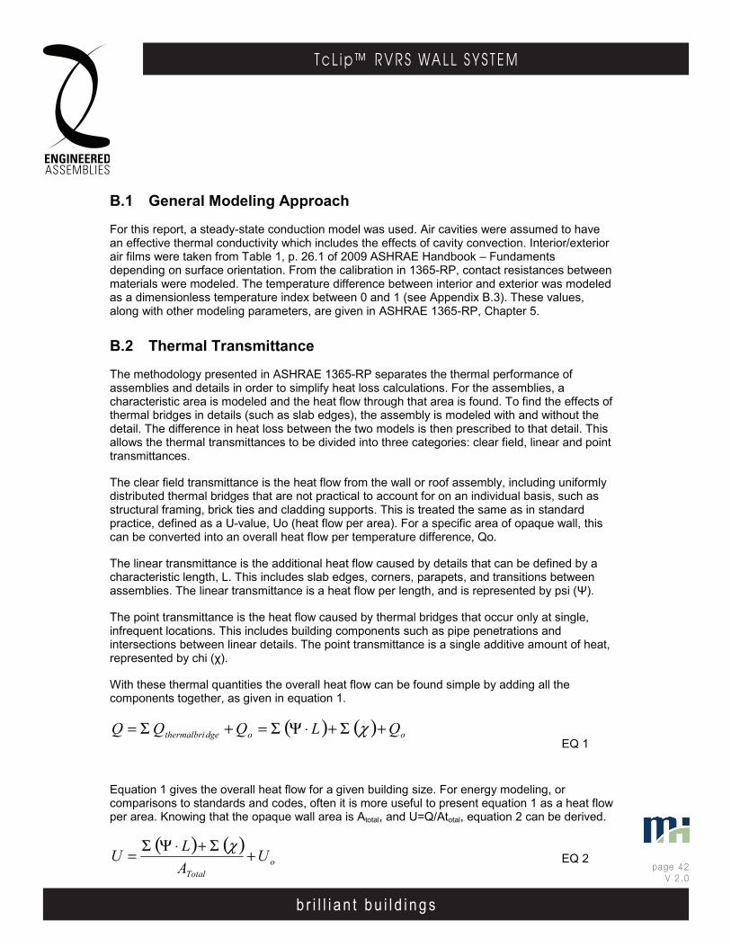
b r i l l i a n t b u i l d i n g s
page 42V 2 .0
T c L i p ™ R V R S WA L L S Y S T E M
b r i l l i a n t b u i l d i n g s
E . A . I . T h E r m A l C l I p r . V. r . S . WA l l S y S T E mEngineered Assembl ies Inc .6535 M i l l c reek D r i ve , Un i t 75M iss i ssauga , On ta r i o , Canada L5N 2M2
T 905 .816 .2218F 905 .816 .9761
E i n fo@eng inee redassemb l i es .comW Eng inee redAssemb l i es .com
page 4103DEC13
b r i l l i a n t b u i l d i n g s
E . A . I . T h E r m A l C l I p r . V. r . S . WA l l S y S T E mEngineered Assembl ies Inc .6535 M i l l c reek D r i ve , Un i t 75M iss i ssauga , On ta r i o , Canada L5N 2M2
T 905 .816 .2218F 905 .816 .9761
E i n fo@eng inee redassemb l i es .comW Eng inee redAssemb l i es .com
page 3206OCT13
B.1 General Modeling Approach
For this report, a steady-state conduction model was used. Air cavities were assumed to have an effective thermal conductivity which includes the effects of cavity convection. Interior/exterior air films were taken from Table 1, p. 26.1 of 2009 ASHRAE Handbook – Fundaments depending on surface orientation. From the calibration in 1365-RP, contact resistances between materials were modeled. The temperature difference between interior and exterior was modeled as a dimensionless temperature index between 0 and 1 (see Appendix B.3). These values, along with other modeling parameters, are given in ASHRAE 1365-RP, Chapter 5.
B.2 Thermal Transmittance
The methodology presented in ASHRAE 1365-RP separates the thermal performance of assemblies and details in order to simplify heat loss calculations. For the assemblies, a characteristic area is modeled and the heat flow through that area is found. To find the effects of thermal bridges in details (such as slab edges), the assembly is modeled with and without the detail. The difference in heat loss between the two models is then prescribed to that detail. This allows the thermal transmittances to be divided into three categories: clear field, linear and point transmittances.
The clear field transmittance is the heat flow from the wall or roof assembly, including uniformly distributed thermal bridges that are not practical to account for on an individual basis, such as structural framing, brick ties and cladding supports. This is treated the same as in standard practice, defined as a U-value, Uo (heat flow per area). For a specific area of opaque wall, this can be converted into an overall heat flow per temperature difference, Qo.
The linear transmittance is the additional heat flow caused by details that can be defined by a characteristic length, L. This includes slab edges, corners, parapets, and transitions between assemblies. The linear transmittance is a heat flow per length, and is represented by psi (Ψ).
The point transmittance is the heat flow caused by thermal bridges that occur only at single, infrequent locations. This includes building components such as pipe penetrations and intersections between linear details. The point transmittance is a single additive amount of heat, represented by chi (χ).
With these thermal quantities the overall heat flow can be found simple by adding all the components together, as given in equation 1.
( ) ( ) oodgethermalbri QLQQQ +Σ+⋅ΨΣ=+Σ= χ
EQ 1
Equation 1 gives the overall heat flow for a given building size. For energy modeling, or comparisons to standards and codes, often it is more useful to present equation 1 as a heat flow per area. Knowing that the opaque wall area is Atotal, and U=Q/Atotal, equation 2 can be derived.
( ) ( )o
Total
UALU +Σ+⋅ΨΣ= χ
EQ 2
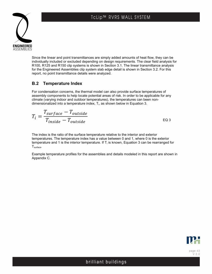
b r i l l i a n t b u i l d i n g s
page 43V 2 .0
T c L i p ™ R V R S WA L L S Y S T E M
b r i l l i a n t b u i l d i n g s
E . A . I . T h E r m A l C l I p r . V. r . S . WA l l S y S T E mEngineered Assembl ies Inc .6535 M i l l c reek D r i ve , Un i t 75M iss i ssauga , On ta r i o , Canada L5N 2M2
T 905 .816 .2218F 905 .816 .9761
E i n fo@eng inee redassemb l i es .comW Eng inee redAssemb l i es .com
page 4203DEC13
b r i l l i a n t b u i l d i n g s
E . A . I . T h E r m A l C l I p r . V. r . S . WA l l S y S T E mEngineered Assembl ies Inc .6535 M i l l c reek D r i ve , Un i t 75M iss i ssauga , On ta r i o , Canada L5N 2M2
T 905 .816 .2218F 905 .816 .9761
E i n fo@eng inee redassemb l i es .comW Eng inee redAssemb l i es .com
page 3306OCT13
Since the linear and point transmittances are simply added amounts of heat flow, they can be individually included or excluded depending on design requirements. The clear field analysis for R100, R125 and R150 clip systems is shown in Section 3.1. The linear transmittance analysis for the Engineered Assemblies clip system slab edge detail is shown in Section 3.2. For this report, no point transmittance details were analyzed.
B.2 Temperature Index
For condensation concerns, the thermal model can also provide surface temperatures of assembly components to help locate potential areas of risk. In order to be applicable for any climate (varying indoor and outdoor temperatures), the temperatures can been non-dimensionalized into a temperature index, Ti, as shown below in Equation 3.
= − −
EQ 3
The index is the ratio of the surface temperature relative to the interior and exterior temperatures. The temperature index has a value between 0 and 1, where 0 is the exterior temperature and 1 is the interior temperature. If Ti is known, Equation 3 can be rearranged for Tsurface.
Example temperature profiles for the assemblies and details modeled in this report are shown in Appendix C.
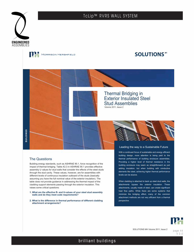
b r i l l i a n t b u i l d i n g s
page 44V 2 .0
T c L i p ™ R V R S WA L L S Y S T E M
b r i l l i a n t b u i l d i n g s
E . A . I . T h E r m A l C l I p r . V. r . S . WA l l S y S T E mEngineered Assembl ies Inc .6535 M i l l c reek D r i ve , Un i t 75M iss i ssauga , On ta r i o , Canada L5N 2M2
T 905 .816 .2218F 905 .816 .9761
E i n fo@eng inee redassemb l i es .comW Eng inee redAssemb l i es .com
page 4303DEC13
b r i l l i a n t b u i l d i n g s
E . A . I . T h E r m A l C l I p r . V. r . S . WA l l S y S T E mEngineered Assembl ies Inc .6535 M i l l c reek D r i ve , Un i t 75M iss i ssauga , On ta r i o , Canada L5N 2M2
T 905 .816 .2218F 905 .816 .9761
E i n fo@eng inee redassemb l i es .comW Eng inee redAssemb l i es .com
page 3406OCT13
Thermal Bridging inExterior Insulated SteelStud Assemblies
Leading the way to a Sustainable Future
BU
ILD
ING
S
With a continued focus of sustainable and energy efficient building design, more attention is being paid to the thermal performance of building enclosure assemblies. Providing a higher level of thermal resistance in the building enclosure may seem as straightforward as just adding insulation, but when building with conductive elements like steel, achieving higher thermal performance levels can be elusive.
When cladding is attached to back up steel stud walls, the attachments bypass the exterior insulation. These attachments, usually made of steel, can create significant heat flow paths. While there are some systems that minimize the bridging effect, many of the common attachment methods are not very efficient from a thermal perspective.
Building energy standards, such as ASHRAE 90.1, force recognition of theimpact of thermal bridging. Table A3.3 in ASHRAE 90.1 provides effectiveassembly U values for stud walls that consider the effects of the steel studsthrough the stud cavity. These values, however, are for assemblies withdifferent levels of continuous insulation outboard of the studs (basicallyassuming you have the full nominal value of the exterior insulation). Thetable does not provide guidance in addressing the thermal impact of thecladding support elements passing through the exterior insulation. Thisraises some critical questions:
1. What are the effective R- and U-values of your steel stud assemblywalls and do they meet code requirements?
2. What is the difference in thermal performance of different claddingattachment arrangements?
The Questions
SOLUTIONS
Volume 2011, Issue 2
SOLUTIONS MH Volume 2011, Issue 2
ion,,
65.
ms.
• structurally efficient cladding support systems• non metallic structural elements• low conductivity thermal breaks
s.
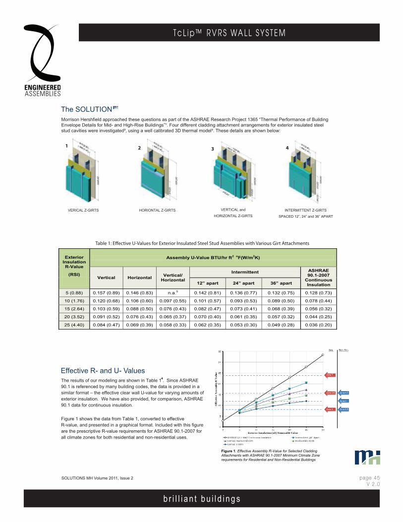
b r i l l i a n t b u i l d i n g s
page 45V 2 .0
T c L i p ™ R V R S WA L L S Y S T E M
b r i l l i a n t b u i l d i n g s
E . A . I . T h E r m A l C l I p r . V. r . S . WA l l S y S T E mEngineered Assembl ies Inc .6535 M i l l c reek D r i ve , Un i t 75M iss i ssauga , On ta r i o , Canada L5N 2M2
T 905 .816 .2218F 905 .816 .9761
E i n fo@eng inee redassemb l i es .comW Eng inee redAssemb l i es .com
page 4403DEC13
b r i l l i a n t b u i l d i n g s
E . A . I . T h E r m A l C l I p r . V. r . S . WA l l S y S T E mEngineered Assembl ies Inc .6535 M i l l c reek D r i ve , Un i t 75M iss i ssauga , On ta r i o , Canada L5N 2M2
T 905 .816 .2218F 905 .816 .9761
E i n fo@eng inee redassemb l i es .comW Eng inee redAssemb l i es .com
page 3506OCT13
Exterior Insulation R-Value
(RSI)
Assembly U-Value BTU/hr ft oF(W/m2K)
Vertical Horizontal Vertical/ Horizontal
Intermittent ASHRAE 90.1-2007
Continuous Insulation 12” apart 24” apart 36” apart
5 (0.88) 0.157 (0.89) 0.146 (0.83) n.a.5 0.142 (0.81) 0.136 (0.77) 0.132 (0.75) 0.128 (0.73)
10 (1.76) 0.120 (0.68) 0.106 (0.60) 0.097 (0.55) 0.101 (0.57) 0.093 (0.53) 0.089 (0.50) 0.078 (0.44)
15 (2.64) 0.103 (0.59) 0.088 (0.50) 0.076 (0.43) 0.082 (0.47) 0.073 (0.41) 0.068 (0.39) 0.056 (0.32)
20 (3.52) 0.091 (0.52) 0.076 (0.43) 0.065 (0.37) 0.070 (0.40) 0.061 (0.35) 0.057 (0.32) 0.044 (0.25)
25 (4.40) 0.084 (0.47) 0.069 (0.39) 0.058 (0.33) 0.062 (0.35) 0.053 (0.30) 0.049 (0.28) 0.036 (0.20)
VERICAL Z-GIRTS HORIONTAL Z-GIRTS INTERMITTENT Z-GIRTS
SPACED 12”, 24” and 36” APART
Effective R- and U- ValuesThe results of our modeling are shown in Table 1 . Since ASHRAE 90.1 is referenced by many building codes, the data is provided in a similar format – the effective clear wall U-value for varying amounts of exterior insulation. We have also provided, for comparison, ASHRAE 90.1 data for continuous insulation.
Figure 1 shows the data from Table 1, converted to effective R-value, and presented in a graphical format. Included with this figure are the prescriptive R-value requirements for ASHRAE 90.1-2007 for all climate zones for both residential and non-residential uses.
VERTICAL and
HORIZONTAL Z-GIRTS
12 3 4
The SOLUTIONMorrison Hershfield approached these questions as part of the ASHRAE Research Project 1365 “Thermal Performance of Building Envelope Details for Mid- and High-Rise Buildings”¹. Four different cladding attachment arrangements for exterior insulated steelstud cavities were investigated², using a well calibrated 3D thermal model³. These details are shown below:
SOLUTIONS MH Volume 2011, Issue 2
Figure 1: Effective Assembly R-Value for Selected CladdingAttachments with ASHRAE 90.1-2007 Minimum Climate Zonerequirements for Residential and Non-Residential Buildings
2
4
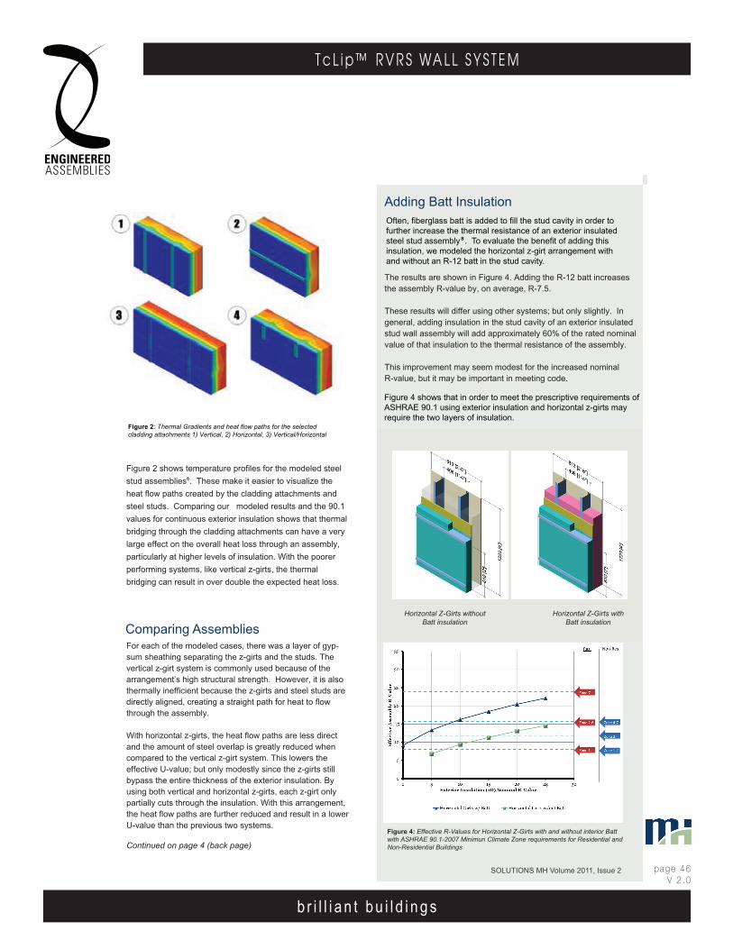
b r i l l i a n t b u i l d i n g s
page 46V 2 .0
T c L i p ™ R V R S WA L L S Y S T E M
b r i l l i a n t b u i l d i n g s
E . A . I . T h E r m A l C l I p r . V. r . S . WA l l S y S T E mEngineered Assembl ies Inc .6535 M i l l c reek D r i ve , Un i t 75M iss i ssauga , On ta r i o , Canada L5N 2M2
T 905 .816 .2218F 905 .816 .9761
E i n fo@eng inee redassemb l i es .comW Eng inee redAssemb l i es .com
page 4503DEC13
b r i l l i a n t b u i l d i n g s
E . A . I . T h E r m A l C l I p r . V. r . S . WA l l S y S T E mEngineered Assembl ies Inc .6535 M i l l c reek D r i ve , Un i t 75M iss i ssauga , On ta r i o , Canada L5N 2M2
T 905 .816 .2218F 905 .816 .9761
E i n fo@eng inee redassemb l i es .comW Eng inee redAssemb l i es .com
page 3606OCT13
Figure 2 shows temperature profiles for the modeled steelstud assemblies . These make it easier to visualize theheat flow paths created by the cladding attachments andsteel studs. Comparing our modeled results and the 90.1values for continuous exterior insulation shows that thermalbridging through the cladding attachments can have a verylarge effect on the overall heat loss through an assembly,particularly at higher levels of insulation. With the poorerperforming systems, like vertical z-girts, the thermalbridging can result in over double the expected heat loss.
SOLUTIONS MH Volume 2011, Issue 2
Adding Batt Insulation
The results are shown in Figure 4. Adding the R-12 batt increases the assembly R-value by, on average, R-7.5.
These results will differ using other systems; but only slightly. In general, adding insulation in the stud cavity of an exterior insulated stud wall assembly will add approximately 60% of the rated nominal value of that insulation to the thermal resistance of the assembly.
This improvement may seem modest for the increased nominal R-value, but it may be important in meeting code.
Horizontal Z-Girts without Batt insulation
Horizontal Z-Girts with Batt insulation
Figure 2: Thermal Gradients and heat flow paths for the selected cladding attachments 1) Vertical, 2) Horizontal, 3) Vertical/Horizontal
Often, fiberglass batt is added to fill the stud cavity in order to further increase the thermal resistance of an exterior insulated steel stud assembly . To evaluate the benefit of adding this insulation, we modeled the horizontal z-girt arrangement with and without an R-12 batt in the stud cavity.
Figure 4: Effective R-Values for Horizontal Z-Girts with and without interior Batt with ASHRAE 90.1-2007 Minimun Climate Zone requirements for Residential and Non-Residential Buildings
Comparing AssembliesFor each of the modeled cases, there was a layer of gyp- sum sheathing separating the z-girts and the studs. The vertical z-girt system is commonly used because of the arrangement’s high structural strength. However, it is also thermally inefficient because the z-girts and steel studs are directly aligned, creating a straight path for heat to flow through the assembly.
With horizontal z-girts, the heat flow paths are less direct and the amount of steel overlap is greatly reduced when compared to the vertical z-girt system. This lowers the effective U-value; but only modestly since the z-girts still bypass the entire thickness of the exterior insulation. By using both vertical and horizontal z-girts, each z-girt only partially cuts through the insulation. With this arrangement, the heat flow paths are further reduced and result in a lower U-value than the previous two systems.
Continued on page 4 (back page)
8
Figure 4 shows that in order to meet the prescriptive requirements of ASHRAE 90.1 using exterior insulation and horizontal z-girts may require the two layers of insulation.
Adding Batt Insulation
The results are shown in Figure 4. Adding the R-12 batt increases the assembly R-value by, on average, R-7.5.
These results will differ using other systems; but only slightly. In general, adding insulation in the stud cavity of an exterior insulated stud wall assembly will add approximately 60% of the rated nominal value of that insulation to the thermal resistance of the assembly.
This improvement may seem modest for the increased nominal R-value, but it may be important in meeting code.
Often, fiberglass batt is added to fill the stud cavity in order to further increase the thermal resistance of an exterior insulated steel stud assembly . To evaluate the benefit of adding this insulation, we modeled the horizontal z-girt arrangement with and without an R-12 batt in the stud cavity.
8
Figure 4 shows that in order to meet the prescriptive requirements of ASHRAE 90.1 using exterior insulation and horizontal z-girts may require the two layers of insulation.
Horizontal Z-Girts without Batt insulation
Horizontal Z-Girts with Batt insulation
Horizontal Z-Girts withoutBatt insulation
Horizontal Z-Girts withBatt insulation

b r i l l i a n t b u i l d i n g s
page 47V 2 .0
T c L i p ™ R V R S WA L L S Y S T E M
b r i l l i a n t b u i l d i n g s
E . A . I . T h E r m A l C l I p r . V. r . S . WA l l S y S T E mEngineered Assembl ies Inc .6535 M i l l c reek D r i ve , Un i t 75M iss i ssauga , On ta r i o , Canada L5N 2M2
T 905 .816 .2218F 905 .816 .9761
E i n fo@eng inee redassemb l i es .comW Eng inee redAssemb l i es .com
page 4603DEC13
b r i l l i a n t b u i l d i n g s
E . A . I . T h E r m A l C l I p r . V. r . S . WA l l S y S T E mEngineered Assembl ies Inc .6535 M i l l c reek D r i ve , Un i t 75M iss i ssauga , On ta r i o , Canada L5N 2M2
T 905 .816 .2218F 905 .816 .9761
E i n fo@eng inee redassemb l i es .comW Eng inee redAssemb l i es .com
page 3706OCT13
BU
ILD
ING
S
Closing
Supplementary Notes
This example provides understanding of the effects of3D bridging in several ‘clear wall’ assemblies. In addition,there are other significant avenues of thermal bridging,including at parapets, slabs, corners etc. that wereanalyzed as part of the ASHRAE Research Project 1365.
As the push towards greater energy efficiency continues, 3D thermal modeling will become anincreasingly useful approach in accurately analyzingthe thermal performance of building envelope systems.
3D thermal modeling is one of the many tools in MH’stoolbox, and combined with extensive field experienceand knowledge, MH can effectively provide solutionsthat are relevant to the design, construction andoperation of the building environment.
1. Report was finalized July, 2011 and is available at ashrae.org
2. For these 4 assemblies, the studs were 3.5in depths at 16”o.c. and the stud cavity was un-insulated. The exterior insulation was varied from R-5 to R-25.
3. Part of MH’s resources is a 3D heat transfer model that was extensively calibrated and validated as part of the ASHRAE Research Project 1365.
4. These are the ‘clear wall’ U-values and includes the effects of the stud wall with no top and bottom tracks. ASHRAE values were taken from ASHRAE 90.1-2007, Table A.3.3. Note that ASHRAE includes both top and bottom steel tracks
5. The vertical section of the vertical/horizontal system always contained R-5 insulation, and the horizontal section was varied between R-5 and R-25. A total value for an exterior insulation of R-5 alone is was not applicable.
6. All images shown are for an exterior insulation of R15.
7. This type of intermittent system is often constrained by structural considerations since the decrease in steel offers less support.
8. Other factors, such as condensation resistance, must also be considered when using batt insulation.
One of the important lessons of this analysis is that to achieve high levels of effective thermal resistance in steel stud walls, itis more important to find ways of eliminating, or thermally breakingthe metal elements passing through the insulation. A number ofsystems have been proposed and used that make use of:
• structurally efficient cladding support systems• non metallic structural elements• low conductivity thermal breaks
It is important to note that there are additional structural and fireresistance implications that need to be considered, as well thethermal performance, when using these systems.
If you wish to discuss how our services can help youmake a difference, please contact us [email protected] or throughyour local Morrison Hershfield office with any questions.
SOLUTIONS MH Volume 2011, Issue 2
The fourth system is a set of intermittent clips that were modeled as 12” inch long pieces of z-girt, aligned vertically at the studs. Figure 3 compares the effect on R-values of the increased spacing and resultant reduction in metal passing through the insulation. With a widely spaced clip, this system gave the best thermal performance out of the four analyzed assemblies .
For all these systems, there is a diminishing return to adding insulation, which can be seen in Figures 1 and 3. For example, going from an R-5 to an R-10 exterior insulation with the horizontal z-girt system, the thermal resistance is increased by R-2.6. If another R-5 of insulation is added, from R-10 to R-15, the thermal resistance this time is only increased by R-1.9.
Figure 3: Effective Assembly R-Value for Intermittently spaced girts with ASHRAE 90.1-2007 Minimum Climate Zone requirements for Residential and Non-Residential Buildings.

b r i l l i a n t b u i l d i n g s
page 48V 2 .0
T c L i p ™ R V R S WA L L S Y S T E M
b r i l l i a n t b u i l d i n g s
E . A . I . T h E r m A l C l I p r . V. r . S . WA l l S y S T E mEngineered Assembl ies Inc .6535 M i l l c reek D r i ve , Un i t 75M iss i ssauga , On ta r i o , Canada L5N 2M2
T 905 .816 .2218F 905 .816 .9761
E i n fo@eng inee redassemb l i es .comW Eng inee redAssemb l i es .com
page 4703DEC13
b r i l l i a n t b u i l d i n g s
E . A . I . T h E r m A l C l I p r . V. r . S . WA l l S y S T E mEngineered Assembl ies Inc .6535 M i l l c reek D r i ve , Un i t 75M iss i ssauga , On ta r i o , Canada L5N 2M2
T 905 .816 .2218F 905 .816 .9761
E i n fo@eng inee redassemb l i es .comW Eng inee redAssemb l i es .com
page 3806OCT13
APPENDIX C – EFFECTIVE ASSEMBLY R-VALUES
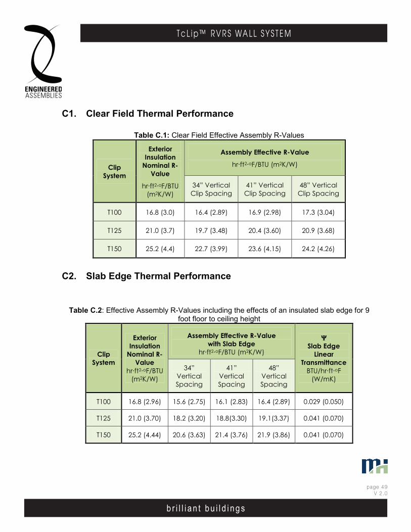
b r i l l i a n t b u i l d i n g s
page 49V 2 .0
T c L i p ™ R V R S WA L L S Y S T E M
b r i l l i a n t b u i l d i n g s
E . A . I . T h E r m A l C l I p r . V. r . S . WA l l S y S T E mEngineered Assembl ies Inc .6535 M i l l c reek D r i ve , Un i t 75M iss i ssauga , On ta r i o , Canada L5N 2M2
T 905 .816 .2218F 905 .816 .9761
E i n fo@eng inee redassemb l i es .comW Eng inee redAssemb l i es .com
page 4803DEC13
b r i l l i a n t b u i l d i n g s
E . A . I . T h E r m A l C l I p r . V. r . S . WA l l S y S T E mEngineered Assembl ies Inc .6535 M i l l c reek D r i ve , Un i t 75M iss i ssauga , On ta r i o , Canada L5N 2M2
T 905 .816 .2218F 905 .816 .9761
E i n fo@eng inee redassemb l i es .comW Eng inee redAssemb l i es .com
page 3906OCT13
C1. Clear Field Thermal Performance
Table C.1: Clear Field Effective Assembly R-Values
Clip System
Exterior Insulation
Nominal R-Value
hr·ft2·oF/BTU (m2K/W)
Assembly Effective R-Value
hr·ft2·oF/BTU (m2K/W)
34” Vertical Clip Spacing
41” Vertical Clip Spacing
48” Vertical Clip Spacing
T100 16.8 (3.0) 16.4 (2.89) 16.9 (2.98) 17.3 (3.04)
T125 21.0 (3.7) 19.7 (3.48) 20.4 (3.60) 20.9 (3.68)
T150 25.2 (4.4) 22.7 (3.99) 23.6 (4.15) 24.2 (4.26)
C2. Slab Edge Thermal Performance
Table C.2: Effective Assembly R-Values including the effects of an insulated slab edge for 9 foot floor to ceiling height
Clip System
Exterior Insulation
Nominal R-Value
hr·ft2·oF/BTU (m2K/W)
Assembly Effective R-Value with Slab Edge
hr·ft2·oF/BTU (m2K/W)
ΨΨΨΨ Slab Edge
Linear Transmittance
BTU/hr·ft·oF (W/mK)
34” Vertical Spacing
41” Vertical Spacing
48” Vertical Spacing
T100 16.8 (2.96) 15.6 (2.75) 16.1 (2.83) 16.4 (2.89) 0.029 (0.050)
T125 21.0 (3.70) 18.2 (3.20) 18.8(3.30) 19.1(3.37) 0.041 (0.070)
T150 25.2 (4.44) 20.6 (3.63) 21.4 (3.76) 21.9 (3.86) 0.041 (0.070)
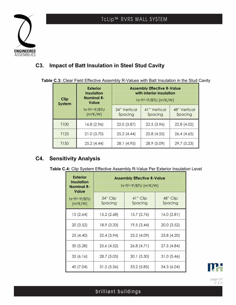
b r i l l i a n t b u i l d i n g s
page 50V 2 .0
T c L i p ™ R V R S WA L L S Y S T E M
b r i l l i a n t b u i l d i n g s
E . A . I . T h E r m A l C l I p r . V. r . S . WA l l S y S T E mEngineered Assembl ies Inc .6535 M i l l c reek D r i ve , Un i t 75M iss i ssauga , On ta r i o , Canada L5N 2M2
T 905 .816 .2218F 905 .816 .9761
E i n fo@eng inee redassemb l i es .comW Eng inee redAssemb l i es .com
page 4903DEC13
b r i l l i a n t b u i l d i n g s
E . A . I . T h E r m A l C l I p r . V. r . S . WA l l S y S T E mEngineered Assembl ies Inc .6535 M i l l c reek D r i ve , Un i t 75M iss i ssauga , On ta r i o , Canada L5N 2M2
T 905 .816 .2218F 905 .816 .9761
E i n fo@eng inee redassemb l i es .comW Eng inee redAssemb l i es .com
page 4006OCT13
C3. Impact of Batt Insulation in Steel Stud Cavity
Table C.3: Clear Field Effective Assembly R-Values with Batt Insulation in the Stud Cavity
Clip System
Exterior Insulation
Nominal R-Value
hr·ft2·oF/BTU (m2K/W)
Assembly Effective R-Value with interior insulation
hr·ft2·oF/BTU (m2K/W)
34” Vertical Spacing
41” Vertical Spacing
48” Vertical Spacing
T100 16.8 (2.96) 22.0 (3.87) 22.5 (3.96) 22.8 (4.02)
T125 21.0 (3.70) 25.2 (4.44) 25.8 (4.55) 26.4 (4.65)
T150 25.2 (4.44) 28.1 (4.95) 28.9 (5.09) 29.7 (5.23)
C4. Sensitivity Analysis
Table C.4: Clip System Effective Assembly R-Value Per Exterior Insulation Level
Exterior Insulation
Nominal R-Value
hr·ft2·oF/BTU (m2K/W)
Assembly Effective R-Value
hr·ft2·oF/BTU (m2K/W)
34” Clip Spacing
41” Clip Spacing
48” Clip Spacing
15 (2.64) 15.2 (2.68) 15.7 (2.76) 16.0 (2.81)
20 (3.52) 18.9 (3.33) 19.5 (3.44) 20.0 (3.52)
25 (4.40) 22.4 (3.94) 23.2 (4.09) 23.8 (4.20)
30 (5.28) 25.6 (4.52) 26.8 (4.71) 27.5 (4.84)
35 (6.16) 28.7 (5.05) 30.1 (5.30) 31.0 (5.46)
40 (7.04) 31.5 (5.56) 33.2 (5.85) 34.3 (6.04)
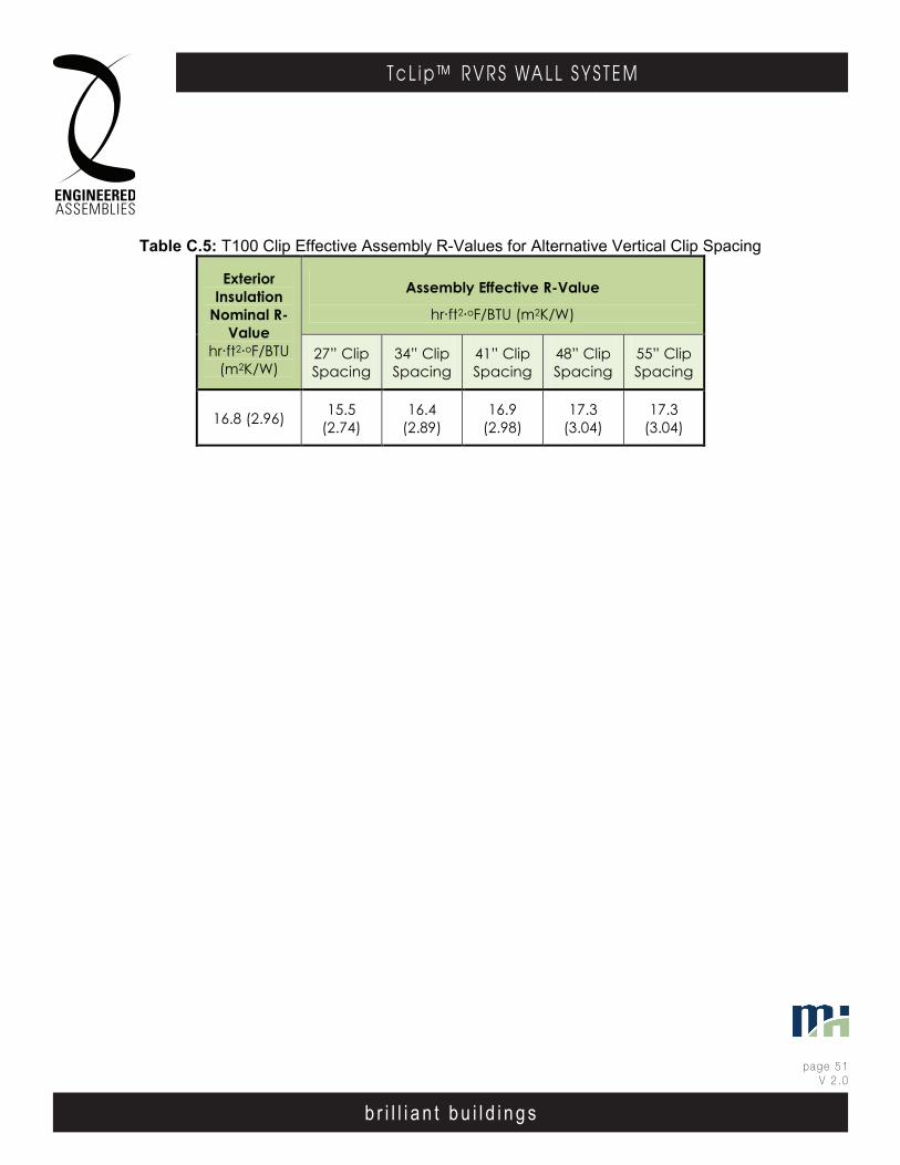
b r i l l i a n t b u i l d i n g s
page 51V 2 .0
T c L i p ™ R V R S WA L L S Y S T E M
b r i l l i a n t b u i l d i n g s
E . A . I . T h E r m A l C l I p r . V. r . S . WA l l S y S T E mEngineered Assembl ies Inc .6535 M i l l c reek D r i ve , Un i t 75M iss i ssauga , On ta r i o , Canada L5N 2M2
T 905 .816 .2218F 905 .816 .9761
E i n fo@eng inee redassemb l i es .comW Eng inee redAssemb l i es .com
page 5003DEC13
b r i l l i a n t b u i l d i n g s
E . A . I . T h E r m A l C l I p r . V. r . S . WA l l S y S T E mEngineered Assembl ies Inc .6535 M i l l c reek D r i ve , Un i t 75M iss i ssauga , On ta r i o , Canada L5N 2M2
T 905 .816 .2218F 905 .816 .9761
E i n fo@eng inee redassemb l i es .comW Eng inee redAssemb l i es .com
page 4106OCT13
Table C.5: T100 Clip Effective Assembly R-Values for Alternative Vertical Clip Spacing
Exterior Insulation
Nominal R-Value
hr·ft2·oF/BTU (m2K/W)
Assembly Effective R-Value
hr·ft2·oF/BTU (m2K/W)
27” Clip Spacing
34” Clip Spacing
41” Clip Spacing
48” Clip Spacing
55” Clip Spacing
16.8 (2.96) 15.5 (2.74)
16.4 (2.89)
16.9 (2.98)
17.3 (3.04)
17.3 (3.04)

b r i l l i a n t b u i l d i n g s
page 52V 2 .0
T c L i p ™ R V R S WA L L S Y S T E M
b r i l l i a n t b u i l d i n g s
E . A . I . T h E r m A l C l I p r . V. r . S . WA l l S y S T E mEngineered Assembl ies Inc .6535 M i l l c reek D r i ve , Un i t 75M iss i ssauga , On ta r i o , Canada L5N 2M2
T 905 .816 .2218F 905 .816 .9761
E i n fo@eng inee redassemb l i es .comW Eng inee redAssemb l i es .com
page 5103DEC13
b r i l l i a n t b u i l d i n g s
E . A . I . T h E r m A l C l I p r . V. r . S . WA l l S y S T E mEngineered Assembl ies Inc .6535 M i l l c reek D r i ve , Un i t 75M iss i ssauga , On ta r i o , Canada L5N 2M2
T 905 .816 .2218F 905 .816 .9761
E i n fo@eng inee redassemb l i es .comW Eng inee redAssemb l i es .com
page 4206OCT13
APPENDIX D – EXAMPLE SIMULATED TEMPERATURE DISTRIBUTION

b r i l l i a n t b u i l d i n g s
page 53V 2 .0
T c L i p ™ R V R S WA L L S Y S T E M
b r i l l i a n t b u i l d i n g s
E . A . I . T h E r m A l C l I p r . V. r . S . WA l l S y S T E mEngineered Assembl ies Inc .6535 M i l l c reek D r i ve , Un i t 75M iss i ssauga , On ta r i o , Canada L5N 2M2
T 905 .816 .2218F 905 .816 .9761
E i n fo@eng inee redassemb l i es .comW Eng inee redAssemb l i es .com
page 5203DEC13
b r i l l i a n t b u i l d i n g s
E . A . I . T h E r m A l C l I p r . V. r . S . WA l l S y S T E mEngineered Assembl ies Inc .6535 M i l l c reek D r i ve , Un i t 75M iss i ssauga , On ta r i o , Canada L5N 2M2
T 905 .816 .2218F 905 .816 .9761
E i n fo@eng inee redassemb l i es .comW Eng inee redAssemb l i es .com
page 4306OCT13
Figure D1: Temperature profile for T125 clip system with clips spaced vertically at 41 inches

b r i l l i a n t b u i l d i n g s
page 54V 2 .0
T c L i p ™ R V R S WA L L S Y S T E M
b r i l l i a n t b u i l d i n g s
E . A . I . T h E r m A l C l I p r . V. r . S . WA l l S y S T E mEngineered Assembl ies Inc .6535 M i l l c reek D r i ve , Un i t 75M iss i ssauga , On ta r i o , Canada L5N 2M2
T 905 .816 .2218F 905 .816 .9761
E i n fo@eng inee redassemb l i es .comW Eng inee redAssemb l i es .com
page 5303DEC13
b r i l l i a n t b u i l d i n g s
E . A . I . T h E r m A l C l I p r . V. r . S . WA l l S y S T E mEngineered Assembl ies Inc .6535 M i l l c reek D r i ve , Un i t 75M iss i ssauga , On ta r i o , Canada L5N 2M2
T 905 .816 .2218F 905 .816 .9761
E i n fo@eng inee redassemb l i es .comW Eng inee redAssemb l i es .com
page 4406OCT13
Figure D2: Temperature profile for T125 clip system with clips spaced 41 in o.c. and slab edge detail
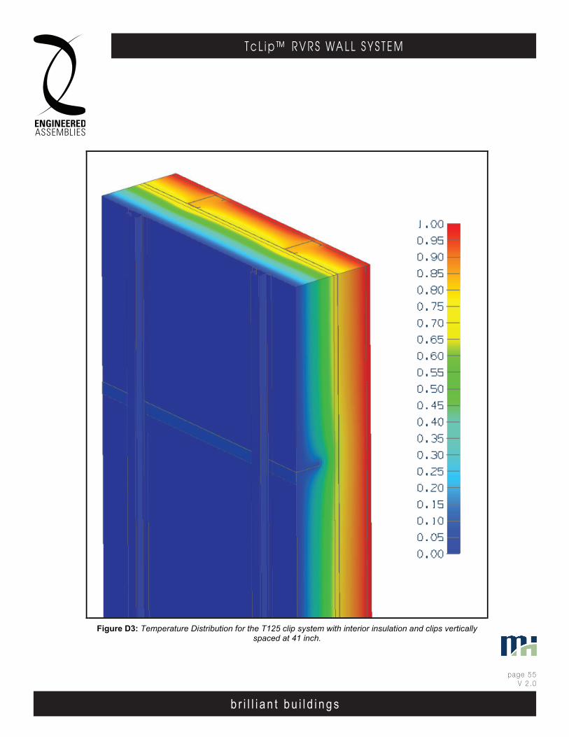
b r i l l i a n t b u i l d i n g s
page 55V 2 .0
T c L i p ™ R V R S WA L L S Y S T E M
b r i l l i a n t b u i l d i n g s
E . A . I . T h E r m A l C l I p r . V. r . S . WA l l S y S T E mEngineered Assembl ies Inc .6535 M i l l c reek D r i ve , Un i t 75M iss i ssauga , On ta r i o , Canada L5N 2M2
T 905 .816 .2218F 905 .816 .9761
E i n fo@eng inee redassemb l i es .comW Eng inee redAssemb l i es .com
page 5403DEC13
b r i l l i a n t b u i l d i n g s
E . A . I . T h E r m A l C l I p r . V. r . S . WA l l S y S T E mEngineered Assembl ies Inc .6535 M i l l c reek D r i ve , Un i t 75M iss i ssauga , On ta r i o , Canada L5N 2M2
T 905 .816 .2218F 905 .816 .9761
E i n fo@eng inee redassemb l i es .comW Eng inee redAssemb l i es .com
page 4506OCT13
Figure D3: Temperature Distribution for the T125 clip system with interior insulation and clips vertically
spaced at 41 inch.

www.equitone.com
Arch.: Delugan Meissl, Vienna
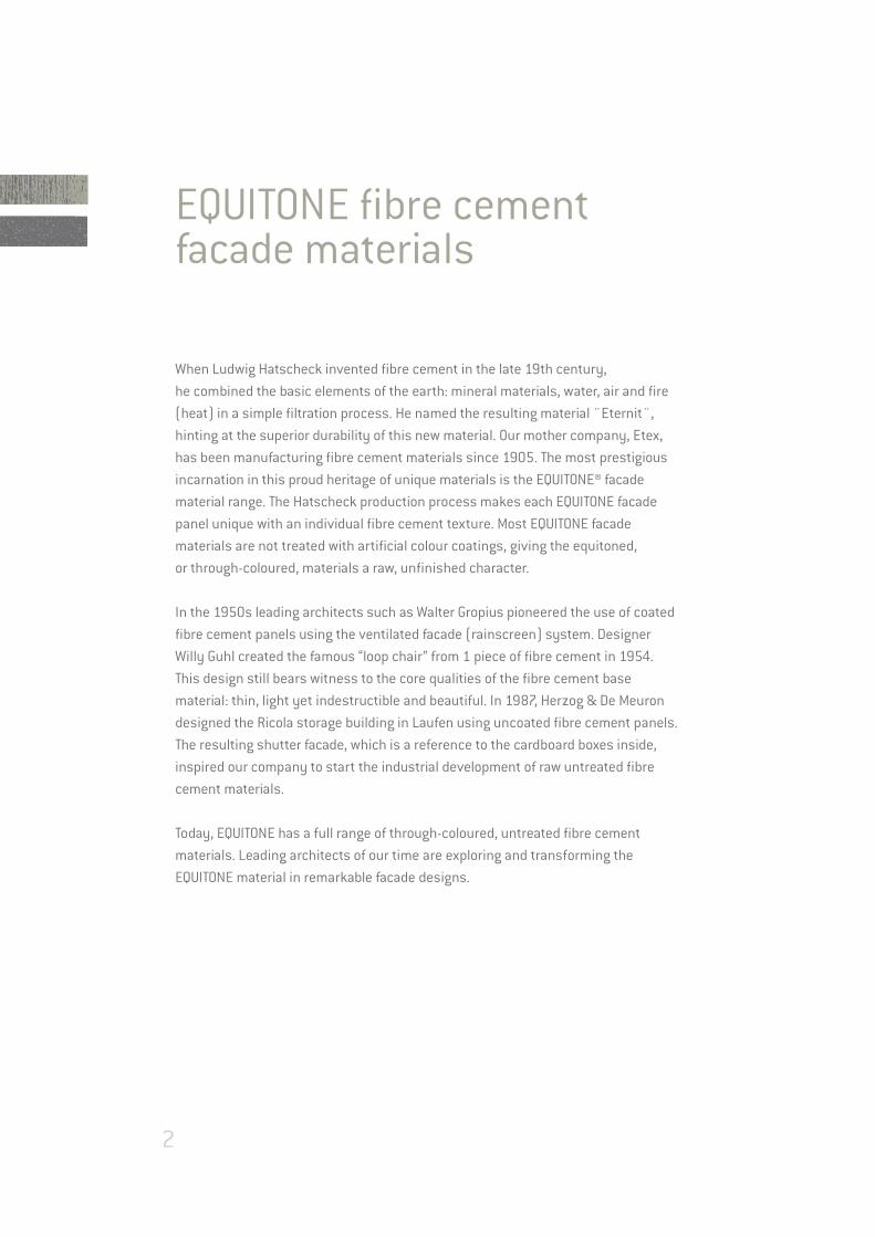
EQUITONE fibre cement facade materials
When Ludwig Hatscheck invented fibre cement in the late 19th century,
he combined the basic elements of the earth: mineral materials, water, air and fire
(heat) in a simple filtration process. He named the resulting material ¨Eternit¨,
hinting at the superior durability of this new material. Our mother company, Etex,
has been manufacturing fibre cement materials since 1905. The most prestigious
incarnation in this proud heritage of unique materials is the EQUITONE® facade
material range. The Hatscheck production process makes each EQUITONE facade
panel unique with an individual fibre cement texture. Most EQUITONE facade
materials are not treated with artificial colour coatings, giving the equitoned,
or through-coloured, materials a raw, unfinished character.
In the 1950s leading architects such as Walter Gropius pioneered the use of coated
fibre cement panels using the ventilated facade (rainscreen) system. Designer
Willy Guhl created the famous “loop chair” from 1 piece of fibre cement in 1954.
This design still bears witness to the core qualities of the fibre cement base
material: thin, light yet indestructible and beautiful. In 1987, Herzog & De Meuron
designed the Ricola storage building in Laufen using uncoated fibre cement panels.
The resulting shutter facade, which is a reference to the cardboard boxes inside,
inspired our company to start the industrial development of raw untreated fibre
cement materials.
Today, EQUITONE has a full range of through-coloured, untreated fibre cement
materials. Leading architects of our time are exploring and transforming the
EQUITONE material in remarkable facade designs.
2

3
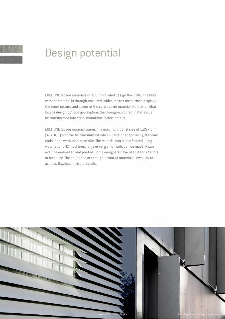
Design potential
EQUITONE facade materials offer unparalleled design flexibility. The fibre
cement material is through-coloured, which means the surface displays
the inner texture and colour of the core eternit material. No matter what
facade design options you explore, the through-coloured materials can
be transformed into crisp, monolithic facade details.
EQUITONE facade material comes in a maximum panel size of 1.25 x 3m
(4´x 10´) and can be transformed into any size or shape using standard
tools in the workshop or on site. The material can be perforated using
waterjet or CNC machines, large or very small cuts can be made, it can
even be embossed and printed. Some designers have used it for interiors
or furniture. The equitoned or through-coloured material allows you to
achieve flawless intricate details.
Arch.: Regina Schineis, Augsburg, GermanyArch.: AR-TE, Leuven, Belgium
4
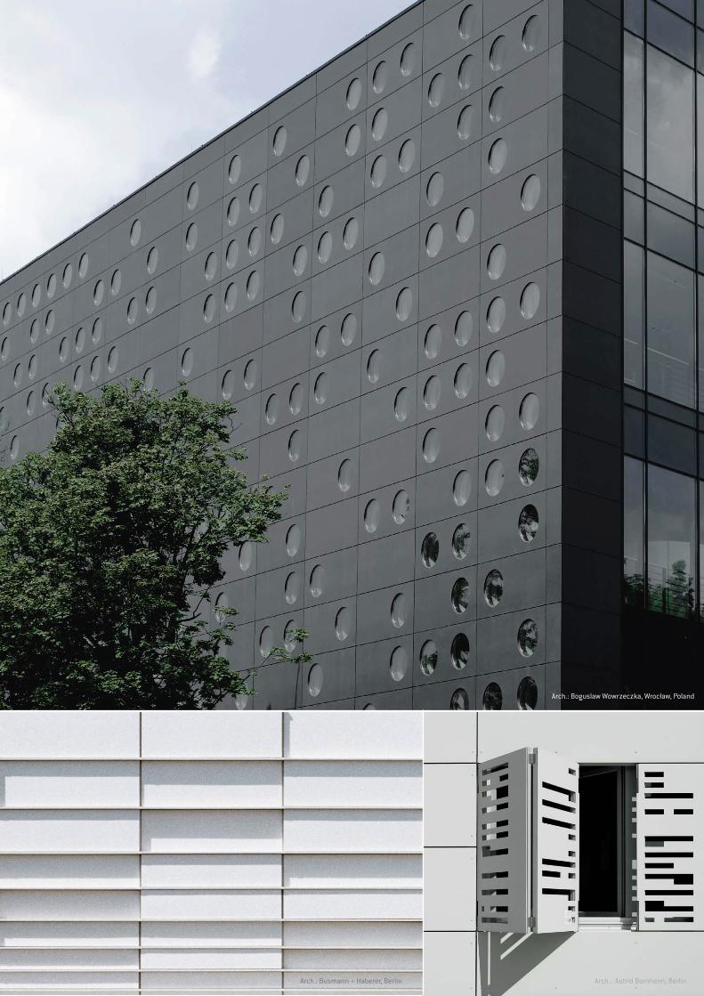
Arch.: Boguslaw Wowrzeczka, Wrocław, Poland
Arch.: Busmann + Haberer, Berlin Arch.: Astrid Bornheim, Berlin
5

EQUITONE, ventilated facadeOriginated in Scandinavia centuries ago, the ventilated facade (rainscreen)
technique is now very prominent in areas with demanding climatic conditions.
This rainscreen system, also known as exterior wall cladding, is composed of two
parts, namely an inner structure coated with an outer protective skin. The outer
panel deflects rain and heat of the sun away from the building. The ventilation
space allows air to freely circulate behind the panel, creating a well ventilated and
comfortable inner building.
Efficiency and durabilityEQUITONE cladding solutions have significant advantages and contribute to
respecting requirements in standards:
• elimination of thermal bridges,
• reduction in the impact of direct solar radiation,
• reduction of structural movements,
• evacuation of moisture and resistant to mould and fungi,
• prevention of condensation inside the building.
Aesthetics and comfortEQUITONE panels clad the building structure and define its character. They
can emphasise the architectural outline of a project or make it blend into its
environment, depending on choices made. In renovation, this solution assures
the inhabitable area is not reduced, and the occupants are not inconvenienced
during the work.
The ventilated facade makes occupants much more comfortable while providing a
more healthy living space. Temperature variations are minimised:
• in winter, the ventilated facade retains heat inside the building and
prevents outside air from cooling the supporting structure.
• in summer when the outside temperature is high, it avoids residual heat
due to ventilation of the air gap.
Attachment systemAttachments may be visible to highlight the modularity of facades, or they may be
discreet and reinforce the material effect, being completely concealed using the
Tergo® invisible attachments system.
Visible fixings
6
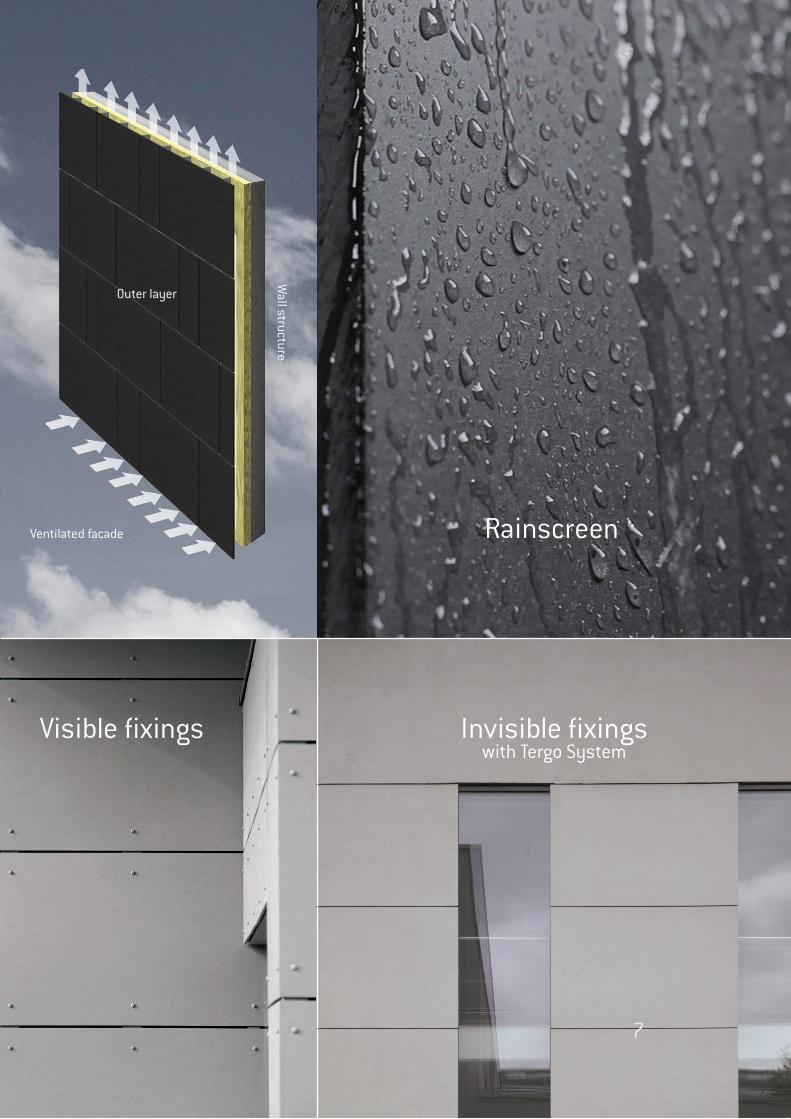
RainscreenW
all structure
Ventilated facade
Outer layer
Visible fixings Invisible fixingswith Tergo System
7
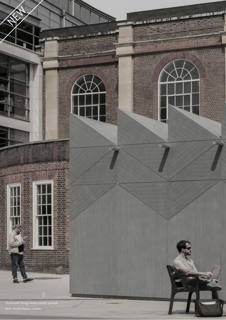
NEW
Clerkenwell Design Week London pavilion
Arch.: Studio Weave, London
8
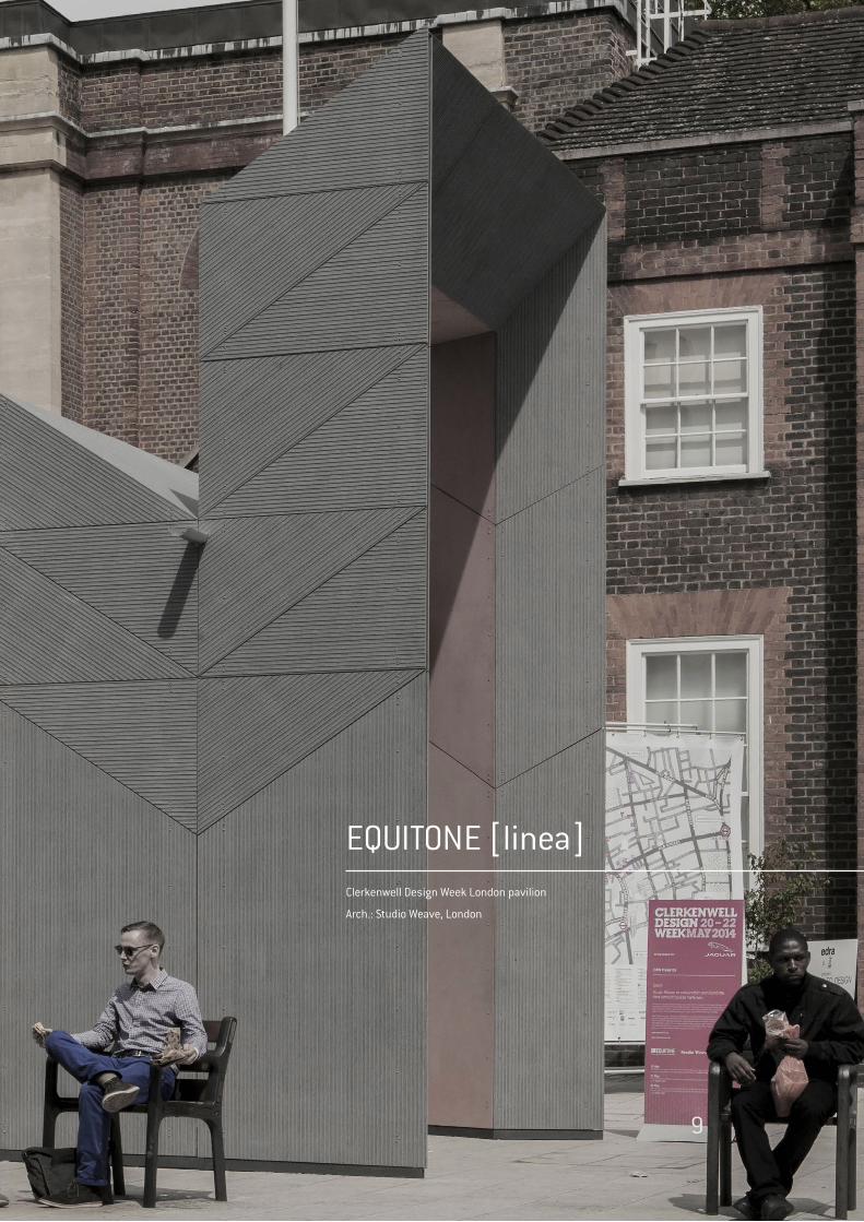
EQUITONE [linea]Clerkenwell Design Week London pavilion
Arch.: Studio Weave, London
9
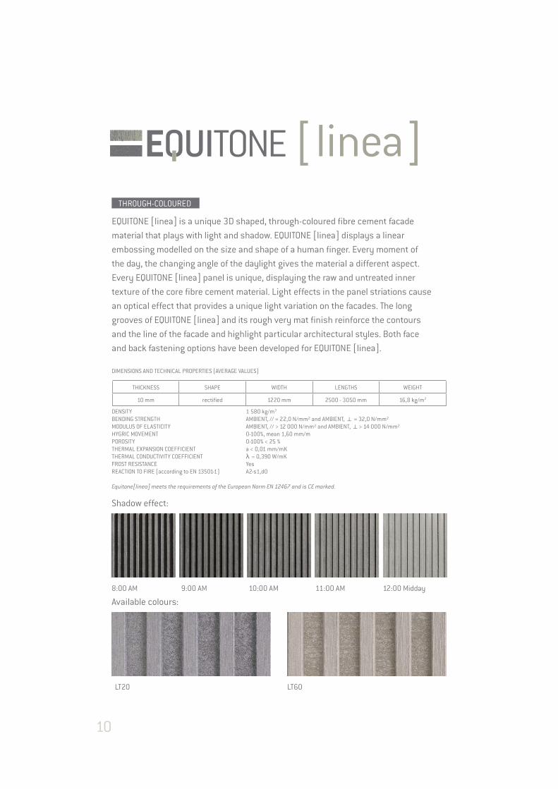
EQUITONE [linea] is a unique 3D shaped, through-coloured fibre cement facade
material that plays with light and shadow. EQUITONE [linea] displays a linear
embossing modelled on the size and shape of a human finger. Every moment of
the day, the changing angle of the daylight gives the material a different aspect.
Every EQUITONE [linea] panel is unique, displaying the raw and untreated inner
texture of the core fibre cement material. Light effects in the panel striations cause
an optical effect that provides a unique light variation on the facades. The long
grooves of EQUITONE [linea] and its rough very mat finish reinforce the contours
and the line of the facade and highlight particular architectural styles. Both face
and back fastening options have been developed for EQUITONE [linea].
Shadow effect:
8:00 AM 9:00 AM 10:00 AM 11:00 AM 12:00 Midday
Available colours:
LT20 LT60
THROUGH-COLOURED
DIMENSIONS AND TECHNICAL PROPERTIES (AVERAGE VALUES)
THICKNESS SHAPE WIDTH LENGTHS WEIGHT
10 mm rectified 1220 mm 2500 - 3050 mm 16,8 kg/m2
DENSITY 1 580 kg/m3 BENDING STRENGTH AMBIENT, // = 22,0 N/mm² and AMBIENT, k = 32,0 N/mm² MODULUS OF ELASTICITY AMBIENT, // > 12 000 N/mm² and AMBIENT, k> 14 000 N/mm² HYGRIC MOVEMENT 0-100%, mean 1,60 mm/m POROSITY 0-100% < 25 % THERMAL EXPANSION COEFFICIENT a < 0,01 mm/mK THERMAL CONDUCTIVITY COEFFICIENT λ = 0,390 W/mK FROST RESISTANCE Yes REACTION TO FIRE (according to EN 13501-1) A2-s1,d0
Equitone[linea] meets the requirements of the European Norm EN 12467 and is CE marked.
10
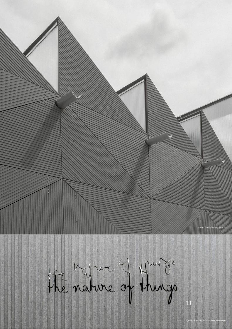
Arch.: Studio Weave, London
EQUITONE shadow art by Fred Eerdekens
11

Belgium - Temse - office building
Arch.: RDBM, Antwerp, Belgium
12
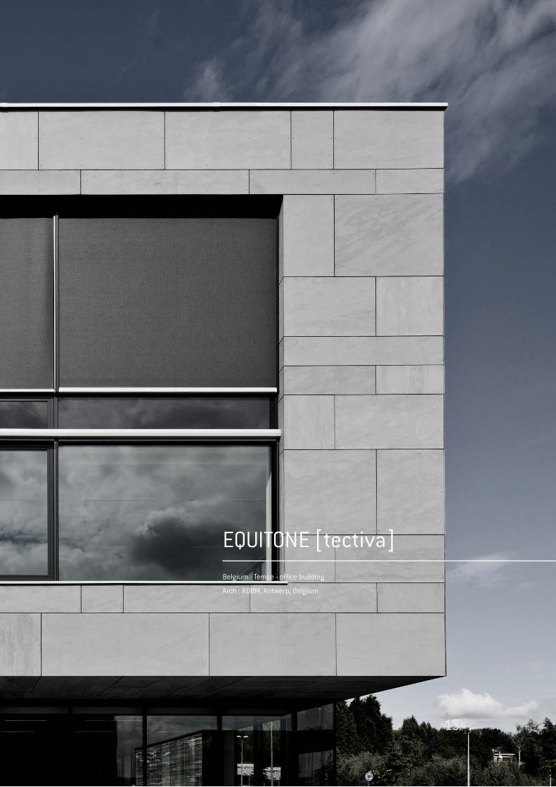
EQUITONE [tectiva]Belgium - Temse - office building
Arch.: RDBM, Antwerp, Belgium
13
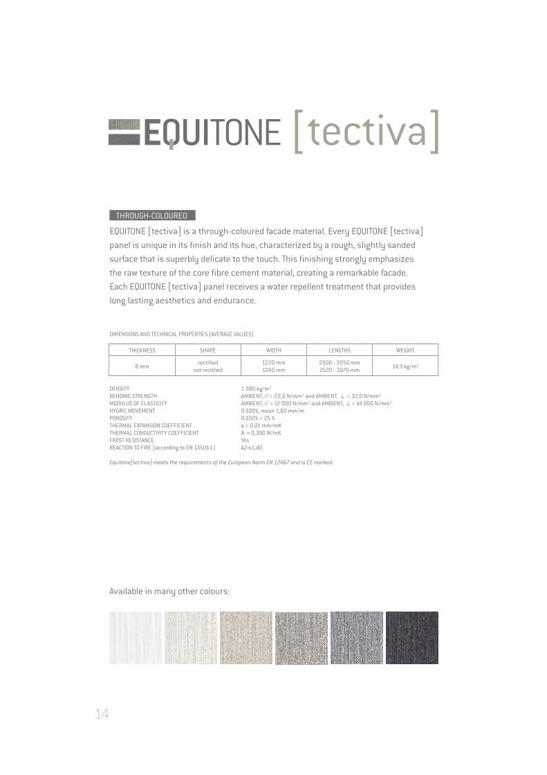
EQUITONE [tectiva] is a through-coloured facade material. Every EQUITONE [tectiva]
panel is unique in its finish and its hue, characterized by a rough, slightly sanded
surface that is superbly delicate to the touch. This finishing strongly emphasizes
the raw texture of the core fibre cement material, creating a remarkable facade.
Each EQUITONE [tectiva] panel receives a water repellent treatment that provides
long lasting aesthetics and endurance.
Available in many other colours:
DIMENSIONS AND TECHNICAL PROPERTIES (AVERAGE VALUES)
THICKNESS SHAPE WIDTH LENGTHS WEIGHT
8 mmrectified
not rectified1220 mm1240 mm
2500 - 3050 mm2520 - 3070 mm
14,9 kg/m²
DENSITY 1 580 kg/m3
BENDING STRENGTH AMBIENT, // = 22,0 N/mm² and AMBIENT, k = 32,0 N/mm²MODULUS OF ELASTICITY AMBIENT, // > 12 000 N/mm² and AMBIENT, k> 14 000 N/mm²HYGRIC MOVEMENT 0-100%, mean 1,60 mm/mPOROSITY 0-100% < 25 % THERMAL EXPANSION COEFFICIENT a < 0,01 mm/mKTHERMAL CONDUCTIVITY COEFFICIENT λ = 0,390 W/mKFROST RESISTANCE YesREACTION TO FIRE (according to EN 13501-1) A2-s1,d0
Equitone[tectiva] meets the requirements of the European Norm EN 12467 and is CE marked.
THROUGH-COLOURED
14
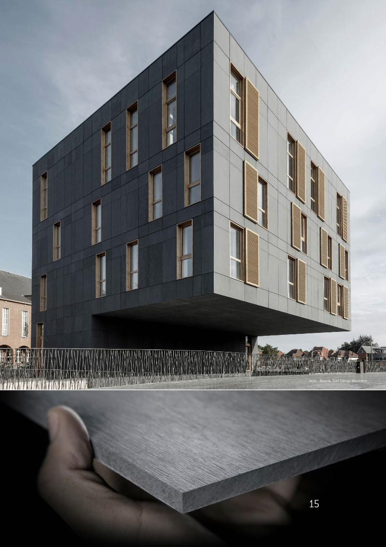
Arch.: Abscis, Sint-Denijs-Westrem
15
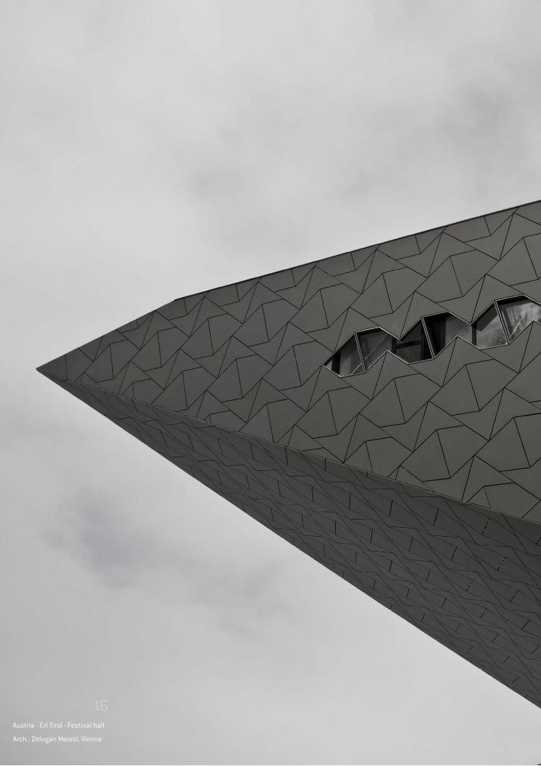
Austria - Erl Tirol - Festival hall
Arch.: Delugan Meissl, Vienna
16
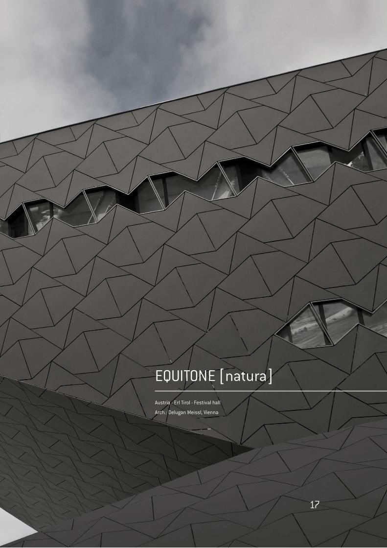
EQUITONE [natura]
Austria - Erl Tirol - Festival hall
Arch.: Delugan Meissl, Vienna
17
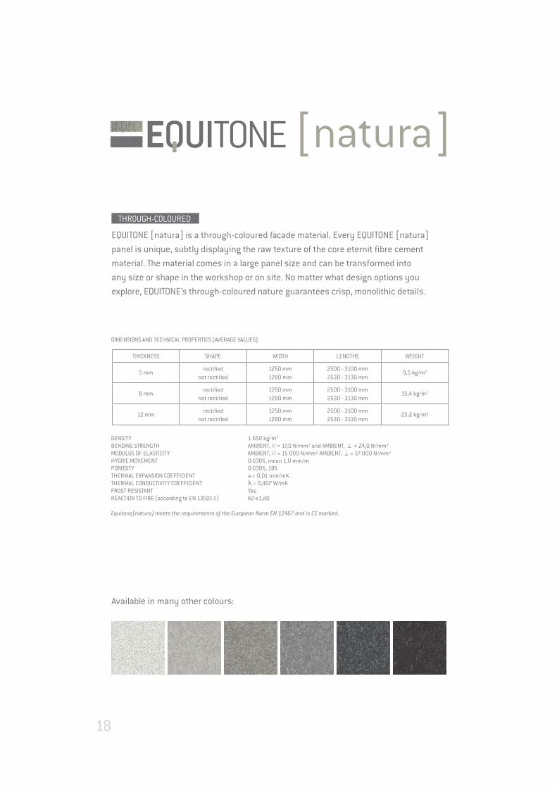
EQUITONE [natura] is a through-coloured facade material. Every EQUITONE [natura]
panel is unique, subtly displaying the raw texture of the core eternit fibre cement
material. The material comes in a large panel size and can be transformed into
any size or shape in the workshop or on site. No matter what design options you
explore, EQUITONE’s through-coloured nature guarantees crisp, monolithic details.
Available in many other colours:
DIMENSIONS AND TECHNICAL PROPERTIES (AVERAGE VALUES)
THICKNESS SHAPE WIDTH LENGTHS WEIGHT
5 mmrectified
not rectified1250 mm1280 mm
2500 - 3100 mm2530 - 3130 mm
9,5 kg/m²
8 mmrectified
not rectified1250 mm1280 mm
2500 - 3100 mm2530 - 3130 mm
15,4 kg/m²
12 mmrectified
not rectified1250 mm1280 mm
2500 - 3100 mm2530 - 3130 mm
23,2 kg/m²
DENSITY 1 650 kg/m3
BENDING STRENGTH AMBIENT, // = 17,0 N/mm² and AMBIENT, k = 24,0 N/mm²MODULUS OF ELASTICITY AMBIENT, // = 15 000 N/mm² AMBIENT, k= 17 000 N/mm²HYGRIC MOVEMENT 0-100%, mean 1,0 mm/mPOROSITY 0-100%, 18%THERMAL EXPANSION COEFFICIENT a < 0,01 mm/mKTHERMAL CONDUCTIVITY COEFFICIENT λ = 0,407 W/mKFROST RESISTANT YesREACTION TO FIRE (according to EN 13501-1) A2-s1,d0
Equitone[natura] meets the requirements of the European Norm EN 12467 and is CE marked.
THROUGH-COLOURED
18

Arch.: DRP Baukunst, Dortmund, Germany
19
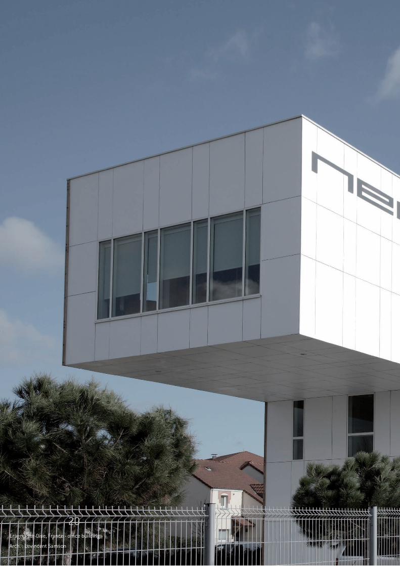
Eragny-sur-Oise, France - office building
Arch. : Levincent Samson
20
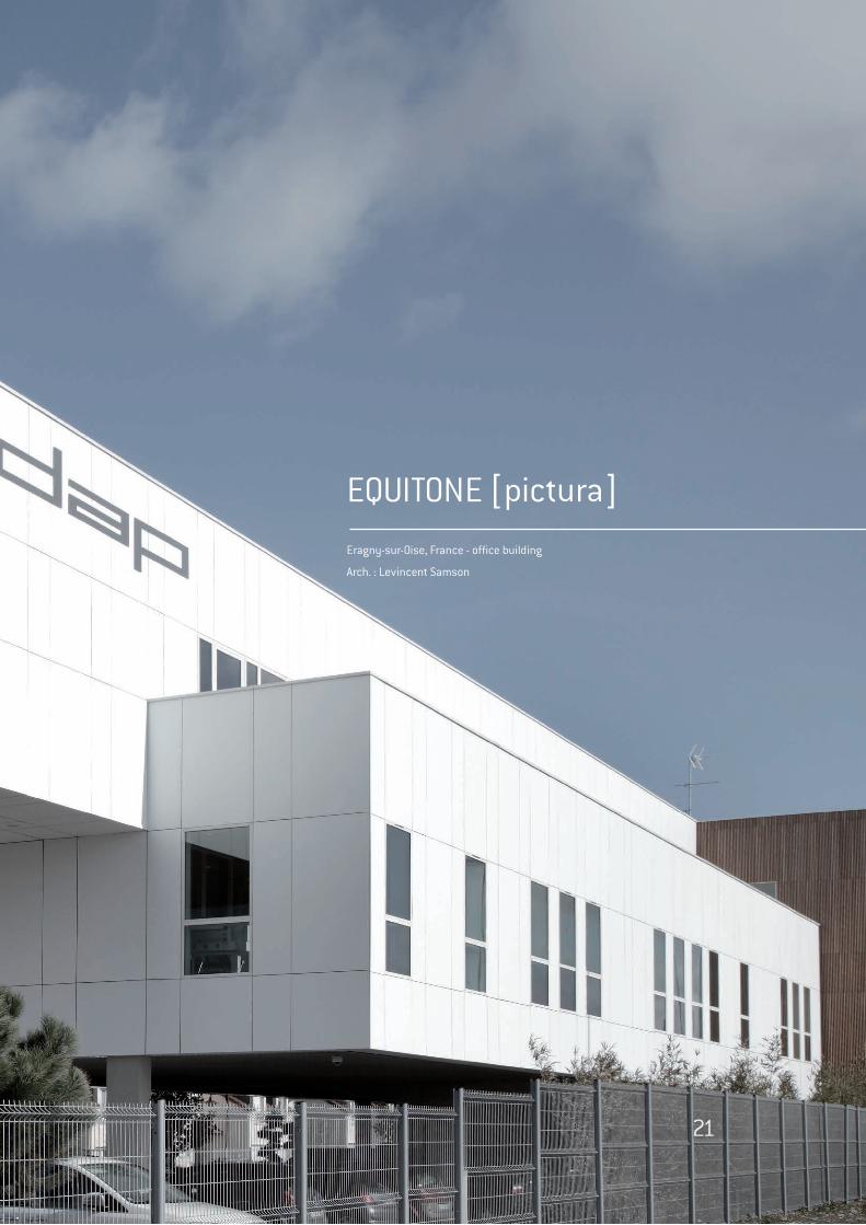
EQUITONE [pictura]
Eragny-sur-Oise, France - office building
Arch. : Levincent Samson
21
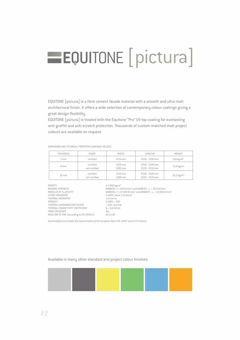
EQUITONE [pictura] is a fibre cement facade material with a smooth and ultra matt
architectural finish. It offers a wide selection of contemporary colour coatings giving a
great design flexibility.
EQUITONE [pictura] is treated with the Equitone “Pro” UV top coating for everlasting
anti-graffiti and anti-scratch protection. Thousands of custom-matched matt project
colours are available on request.
Available in many other standard and project colour finishes:
DIMENSIONS AND TECHNICAL PROPERTIES (AVERAGE VALUES)
THICKNESS SHAPE WIDTH LENGTHS WEIGHT
5 mm rectified 1220 mm 2500 - 3100 mm 8,8 kg/m²
8 mmrectified
not rectified1250 mm1280 mm
2500 - 3100 mm2530 - 3130 mm
15,4 kg/m²
12 mmrectified
not rectified1250 mm1280 mm
2500 - 3100 mm2530 - 3130 mm
23,2 kg/m²
DENSITY ≥ 1 650 kg/m3
BENDING STRENGTH AMBIENT, // =17,0 N/mm² and AMBIENT, k = 26,0 N/mm²MODULUS OF ELASTICITY AMBIENT, // =15 000 N/mm² and AMBIENT, k = 15 000 N/mm²HYGRIC MOVEMENT 0-100%, mean 1,0 mm/mTHERMAL MOVEMENT 1,0 mm/mPOROSITY 0-100% > 20%THERMAL EXPANSION COEFFICIENT < 0,01 mm/mKTHERMAL CONDUCTIVITY COEFFICIENT λ = 0,6 W/mKFROST RESISTANT YesREACTION TO FIRE (according to EN 13501-1) A2-s1,d0 Equitone[pictura] meets the requirements of the European Norm EN 12467 and is CE marked.
22

Arch.: Jo Coenen, Amsterdam
23
equitone.compinterest.com/equitonefacade
Paper from responsible sources100% From well-managed forests
Ed. 1, May 2015
Euro Panels Overseas NVBormstraat 24 - 2830 Willebroek - Belgium
T +32 (0)15 71 73 80 - F +32 (0)15 71 73 89 - [email protected] - www.europanels.net
EQUITONE material sampler
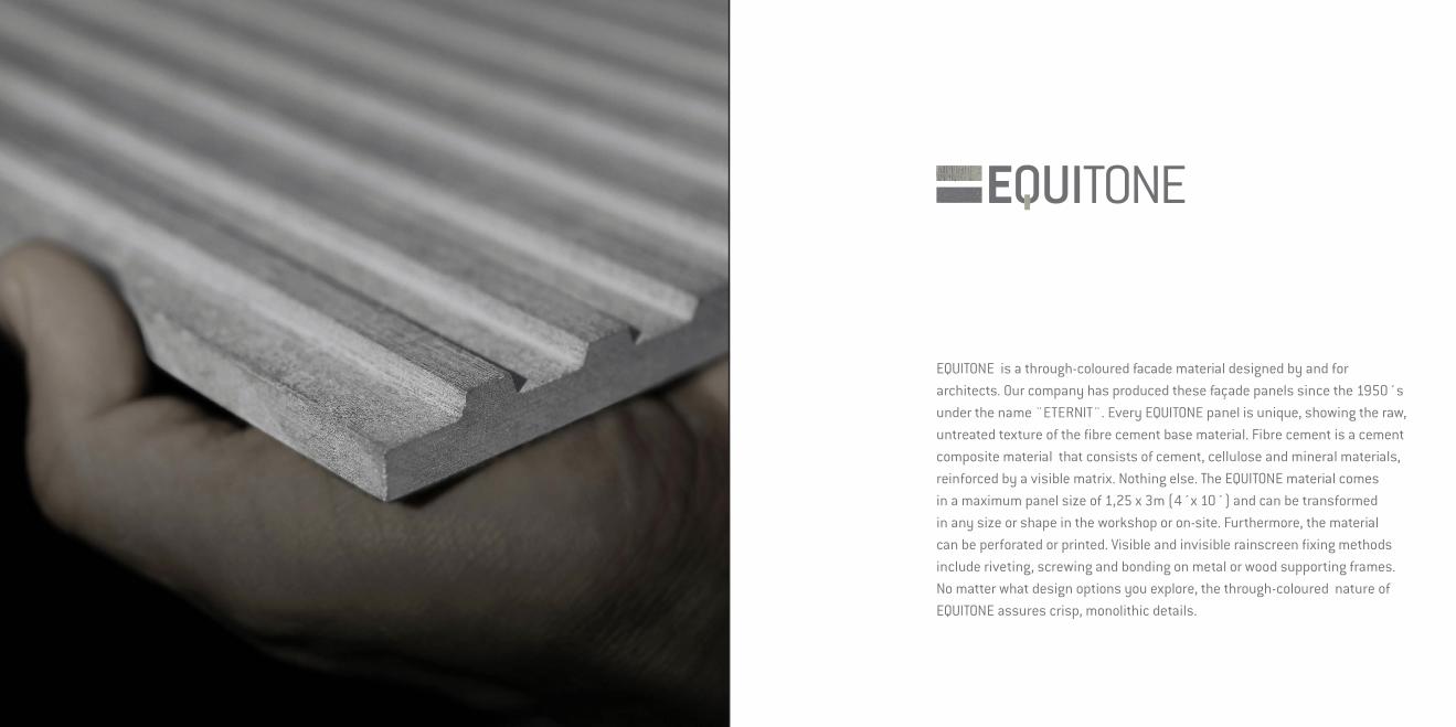
EQUITONE is a through-coloured facade material designed by and for architects. Our company has produced these façade panels since the 1950´s under the name ¨ETERNIT¨. Every EQUITONE panel is unique, showing the raw, untreated texture of the fibre cement base material. Fibre cement is a cement composite material that consists of cement, cellulose and mineral materials, reinforced by a visible matrix. Nothing else. The EQUITONE material comes in a maximum panel size of 1,25 x 3m (4´x 10´) and can be transformed in any size or shape in the workshop or on-site. Furthermore, the material can be perforated or printed. Visible and invisible rainscreen fixing methods include riveting, screwing and bonding on metal or wood supporting frames. No matter what design options you explore, the through-coloured nature of EQUITONE assures crisp, monolithic details.
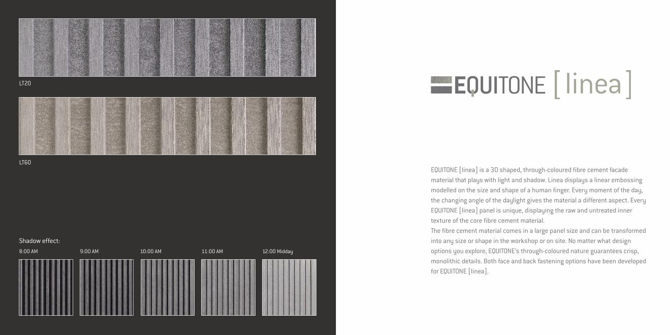
LT20
LT60
Shadow effect:8:00 AM 9:00 AM 10:00 AM 11:00 AM 12:00 Midday
EQUITONE [linea] is a 3D shaped, through-coloured fibre cement facade material that plays with light and shadow. Linea displays a linear embossing modelled on the size and shape of a human finger. Every moment of the day, the changing angle of the daylight gives the material a different aspect. Every EQUITONE [linea] panel is unique, displaying the raw and untreated inner texture of the core fibre cement material. The fibre cement material comes in a large panel size and can be transformed into any size or shape in the workshop or on site. No matter what design options you explore, EQUITONE’s through-coloured nature guarantees crisp, monolithic details. Both face and back fastening options have been developed for EQUITONE [linea].
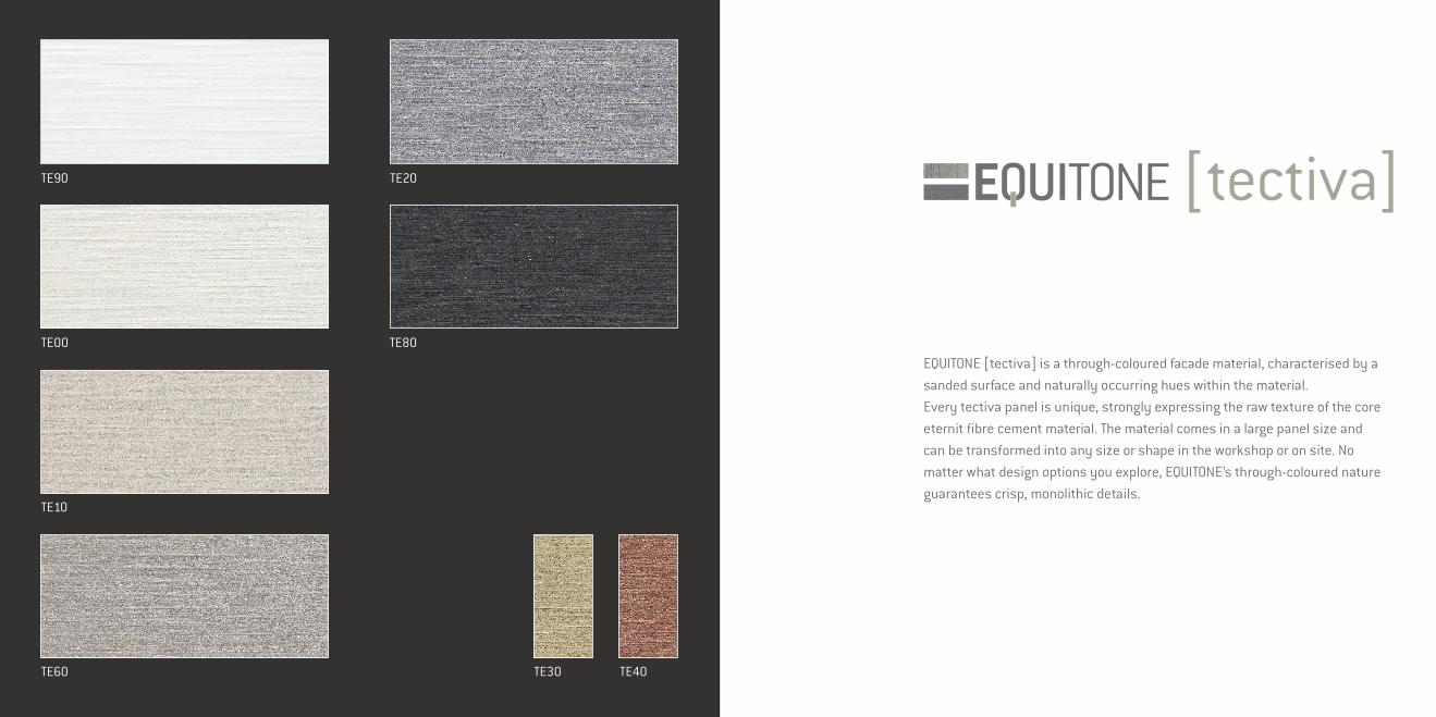
TE00
TE90
TE10
TE60
TE20
TE80
TE30 TE40
EQUITONE [tectiva] is a through-coloured facade material, characterised by a sanded surface and naturally occurring hues within the material. Every tectiva panel is unique, strongly expressing the raw texture of the core eternit fibre cement material. The material comes in a large panel size and can be transformed into any size or shape in the workshop or on site. No matter what design options you explore, EQUITONE’s through-coloured nature guarantees crisp, monolithic details.
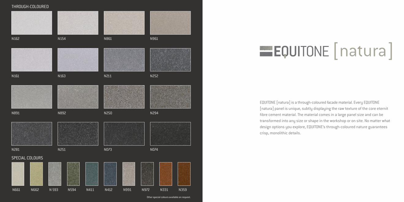
EQUITONE [natura] is a through-coloured facade material. Every EQUITONE [natura] panel is unique, subtly displaying the raw texture of the core eternit fibre cement material. The material comes in a large panel size and can be transformed into any size or shape in the workshop or on site. No matter what design options you explore, EQUITONE’s through-coloured nature guarantees crisp, monolithic details.
THROUGH-COLOURED
SPECIAL COLOURS
N661 N662 N 593 N594 N411 N412 N991 N972 N331 N359
N281
Other special colours available on request.
N891
N161
N162
N251
N892
N163
N154
N073
N250
N211
N861
N074
N294
N252
N961

PG 641
PG 642
PG 542
PW 841
PW 141
PG 544
PG 545
PG 546
PG 843
PG 243
PG 442
PG 443
PG 444
PG 844
PG 241
PG 742
PG 341
PG 342
PA 944
PA 041
EQUITONE [pictura] is an eternit fibre cement facade material with ultra matt architectural finish. Thousands of custom-matched matt project colours are available on request. The material comes in a large panel size and can be transformed into any size or shape in the workshop or on site. The material can also be perforated or printed. No matter what design options you explore, the EQUITONE material is ideal for crisp detailing.
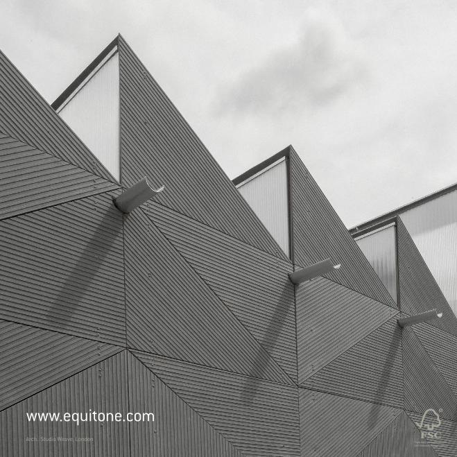
Paper from responsible sources100% From well-managed forests
Arch.: Studio Weave, London
www.equitone.com
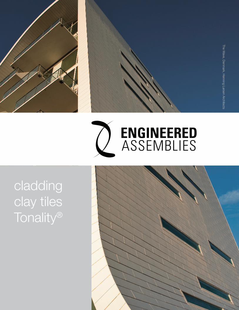
1
claddingclay tilesTonality®
The Wave, D
enmark, H
enning Larsen Architects
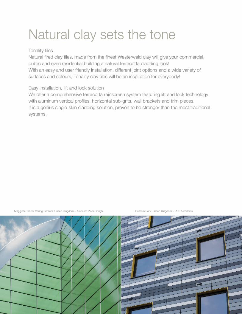
2
Natural clay sets the toneTonality tilesNatural fired clay tiles, made from the finest Westerwald clay will give your commercial, public and even residential building a natural terracotta cladding look!With an easy and user friendly installation, different joint options and a wide variety of surfaces and colours, Tonality clay tiles will be an inspiration for everybody!
Easy installation, lift and lock solutionWe offer a comprehensive terracotta rainscreen system featuring lift and lock technology with aluminum vertical profiles, horizontal sub-grits, wall brackets and trim pieces.It is a genius single-skin cladding solution, proven to be stronger than the most traditional systems.
Maggie’s Cancer Caring Centers, United Kingdom – Architect Piers Gough Barham Park, United Kingdom – PRP Architects

3
Fine surface
Solid
Longlasting

4
ContentsProduct Overview Preface 5 Ventilated Façade 6 Advantages 10 Colour Chart 12 TONALITY® Adaptive Fixing System 15 Sun Protection 17 Product Overview 19 TONLAITY® Classic 21 TONALITY® Baguettes, Lamelle Tiles & Square-shaped Quadrats 23
System Construction TONALITY® System Sub-Construction Adaptive & Standard Details System on Metal Sub-Construction 25 TONALITY® System Sub-Construction Adaptive System on Wooden Sub-Construction 31 TONALITY® Adaptive System T-Line® 32 TONALITY® Adaptive System Siding® 34
Planning Basics General & Technical Information on & Installation TONALITY® Cladding Tiles 36 Round Walls with Standard Cladding Tiles 41 Special Designs 42
References Engineered Assemblies brilliant buildings 43
Technical status 02/2014All notes, technical and graphic information correspond to the current state of the art and to our experience based on this. The installers described are examples and do not take into consideration the conditions specific to individual cases. The information given and the suitability of the materials for their proposed use must be checked by the purchaser in all cases. We (companies of Etex group) accept no liability. This also applies in respect to misprints and subsequent change of a technical nature.
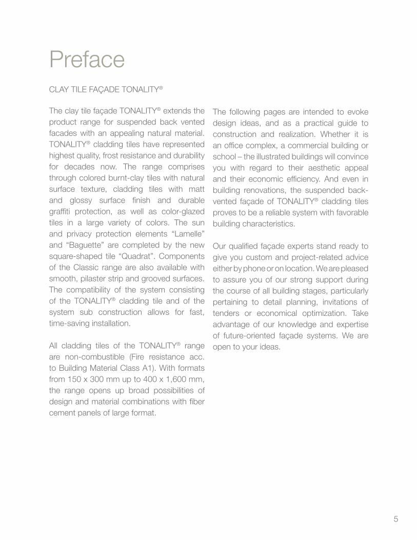
5
PrefaceCLAY TILE FAçADE TONALITY®
The clay tile façade TONALITY® extends the product range for suspended back vented facades with an appealing natural material. TONALITY® cladding tiles have represented highest quality, frost resistance and durability for decades now. The range comprises through colored burnt-clay tiles with natural surface texture, cladding tiles with matt and glossy surface finish and durable graffiti protection, as well as color-glazed tiles in a large variety of colors. The sun and privacy protection elements “Lamelle” and “Baguette” are completed by the new square-shaped tile “Quadrat”. Components of the Classic range are also available with smooth, pilaster strip and grooved surfaces. The compatibility of the system consisting of the TONALITY® cladding tile and of the system sub construction allows for fast, time-saving installation.
All cladding tiles of the TONALITY® range are non-combustible (Fire resistance acc. to Building Material Class A1). With formats from 150 x 300 mm up to 400 x 1,600 mm, the range opens up broad possibilities of design and material combinations with fiber cement panels of large format.
The following pages are intended to evoke design ideas, and as a practical guide to construction and realization. Whether it is an office complex, a commercial building or school – the illustrated buildings will convince you with regard to their aesthetic appeal and their economic efficiency. And even in building renovations, the suspended back-vented façade of TONALITY® cladding tiles proves to be a reliable system with favorable building characteristics.
Our qualified façade experts stand ready to give you custom and project-related advice either by phone or on location. We are pleased to assure you of our strong support during the course of all building stages, particularly pertaining to detail planning, invitations of tenders or economical optimization. Take advantage of our knowledge and expertise of future-oriented façade systems. We are open to your ideas.
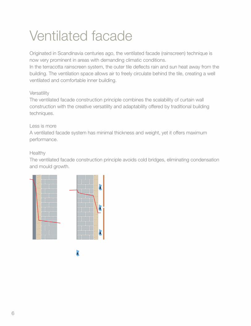
6
Ventilated facadeOriginated in Scandinavia centuries ago, the ventilated facade (rainscreen) technique is now very prominent in areas with demanding climatic conditions.In the terracotta rainscreen system, the outer tile deflects rain and sun heat away from the building. The ventilation space allows air to freely circulate behind the tile, creating a well ventilated and comfortable inner building.
VersatilityThe ventilated facade construction principle combines the scalability of curtain wallconstruction with the creative versatility and adaptability offered by traditional buildingtechniques.
Less is moreA ventilated facade system has minimal thickness and weight, yet it offers maximum performance.
HealthyThe ventilated facade construction principle avoids cold bridges, eliminating condensation and mould growth.

7
Terracotta rainscreen
Ventilation spaceOuter layer
Fixing system
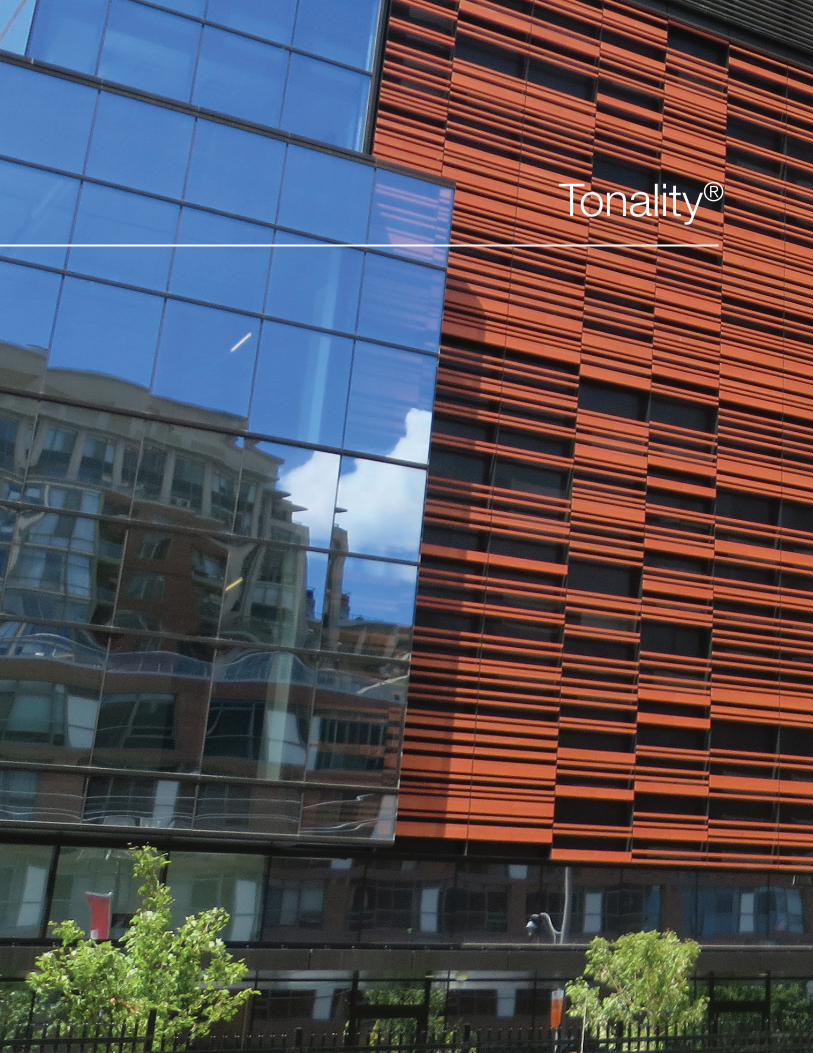
8
Tonality®
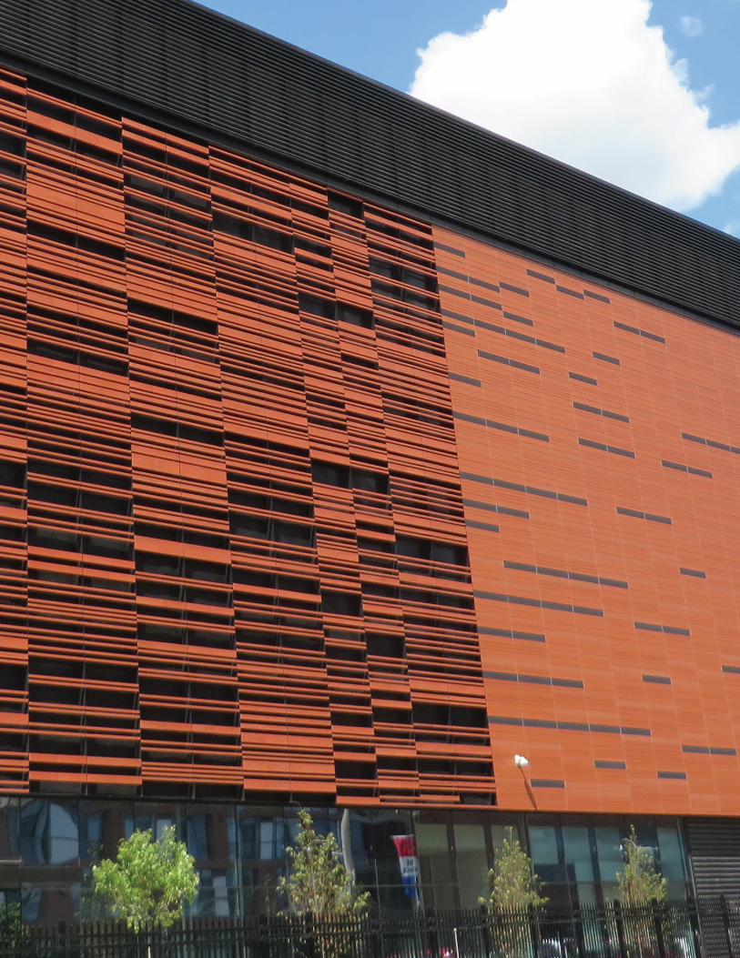
9
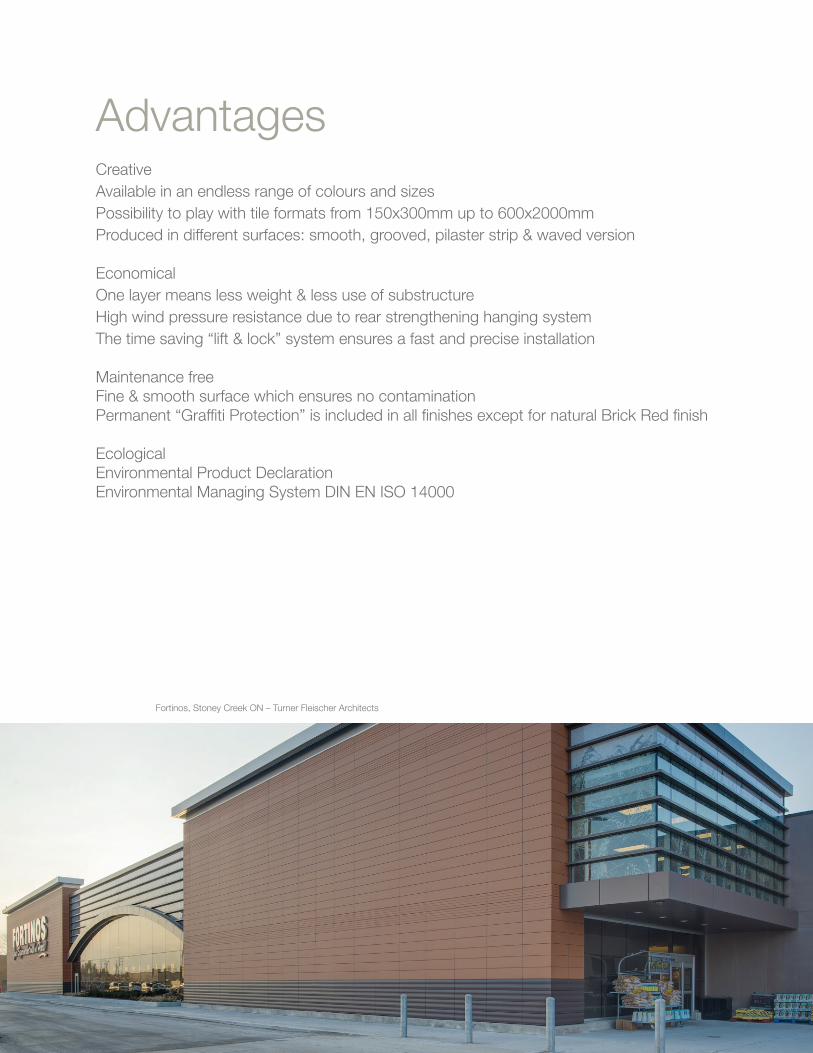
10
AdvantagesCreativeAvailable in an endless range of colours and sizesPossibility to play with tile formats from 150x300mm up to 600x2000mmProduced in different surfaces: smooth, grooved, pilaster strip & waved version
EconomicalOne layer means less weight & less use of substructureHigh wind pressure resistance due to rear strengthening hanging systemThe time saving “lift & lock” system ensures a fast and precise installation
Maintenance freeFine & smooth surface which ensures no contaminationPermanent “Graffiti Protection” is included in all finishes except for natural Brick Red finish
EcologicalEnvironmental Product DeclarationEnvironmental Managing System DIN EN ISO 14000
Fortinos, Stoney Creek ON – Turner Fleischer Architects
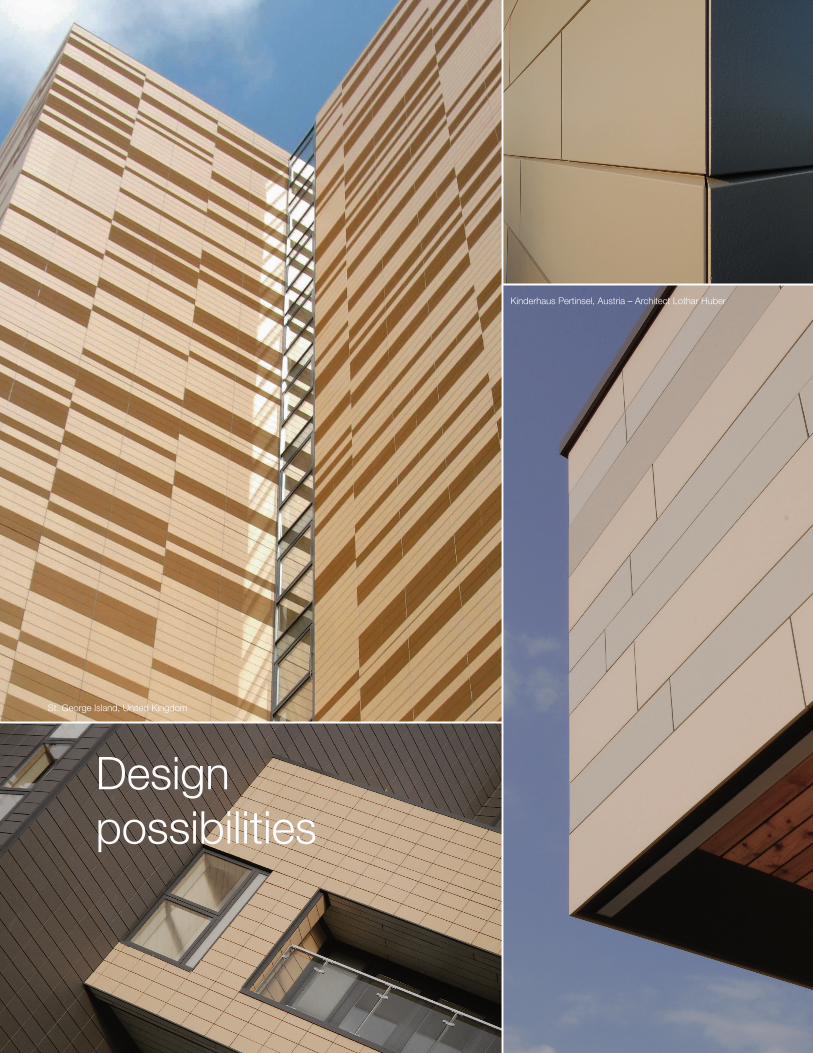
11
St. George Island, United Kingdom
Design possibilities
Kinderhaus Pertinsel, Austria – Architect Lothar Huber
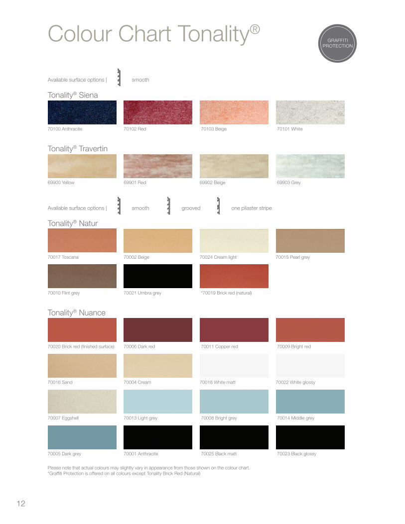
12
Colour Chart Tonality®
Available surface options | smooth
Tonality® Siena
70100 Anthracite 70102 Red 70103 Beige 70101 White
Tonality® Travertin
69900 Yellow 69901 Red 69902 Beige 69903 Grey
Available surface options | smooth
grooved one pilaster stripe
Tonality® Natur
70017 Toscana 70002 Beige 70024 Cream light 70015 Pearl grey
70010 Flint grey 70021 Umbra grey *70019 Brick red (natural)
Tonality® Nuance
70020 Brick red (finished surface) 70006 Dark red 70011 Copper red 70009 Bright red
70016 Sand 70004 Cream 70018 White matt 70022 White glossy
70007 Eggshell 70013 Light grey 70008 Bright grey 70014 Middle grey
70005 Dark grey 70001 Anthracite 70025 Black matt 70023 Black glossy
Please note that actual colours may slightly vary in appearance from those shown on the colour chart.*Graffiti Protection is offered on all colours except Tonality Brick Red (Natural)
GRAFFITIPROTECTION
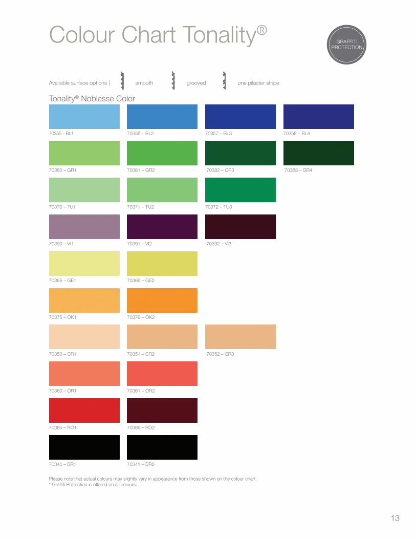
13
Colour Chart Tonality®
Available surface options | smooth
grooved one pilaster stripe
Tonality® Noblesse Color
70355 – BL1 70356 – BL2 70357 – BL3 70358 – BL4
70380 – GR1 70381 – GR2 70382 – GR3 70383 – GR4
70370 – TU1 70371 – TU2 70372 – TU3
70390 – VI1 70391 – VI2 70392 – VI3
70365 – GE1 70366 – GE2
70375 – OK1 70376 – OK2
70350 – CR1 70351 – CR2 70352 – CR3
70360 – OR1 70361 – OR2
70385 – RO1 70386 – RO2
70340 – BR1 70341 – BR2
Please note that actual colours may slightly vary in appearance from those shown on the colour chart.* Graffiti Protection is offered on all colours.
GRAFFITIPROTECTION

14
Cladding tile tonality®
TONALITY® cladding tiles have
represented highest quality, frost
resistance and durability for decades
now.
The unique variety of colors with select
surfaces, the outstandingly attractive
joint design, and the consumer
oriented installation constitute the
distinguishing features of the high
quality cladding tiles TONALITY®.
The suspended back vented
façade of TONALITY® cladding tiles
proved to be a reliable system with
desirable building characteristics for
new building projects as well as for
renovations of existing buildings.
TONALITY® Classic Natural
TONALITY® Classic Finished Surface
TONALITY® Classic Special Series
TONALITY® Color
TONALITY® Color Natural Red FR3
TONALITY® Sun Protection
All notes and information, technical and graphic instructions, correspond to the current codes and standards of technology, as well as to our experiences based on this technology. The described applications represent examples and do not take into consideration custom designs and circumstances of individual cases. The information and the suitability of the material for the intended purposes must be examined with regard to the respective building project at any rate. Liability is excluded. This shall also apply to misprints and later changes of technical data.

15
Tonality® ADS Fixing SystemApplicationsThe Tonality Adaptive System (ADS) can be fastened on a horizontal or vertical primary substructure. This system is the preferred option for large surfaces and complex facades.
The primary substructure is subject to structural analysis suited to the respective building project and does not constitute a component of the Tonality® system range.
1 Tonality® Cladding tile
2 Tonality® Adaptive vertical profile aluminium
3 Tonality® Adaptive joint profile aluminium
4 Tonality® Protection against dismantling
5 Primary substructure aluminium L -profile
6 Primary substructure aluminium wall fastening
Open
joint profile
Closed
joint profile
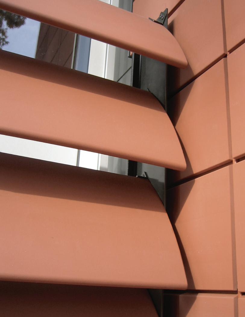
16
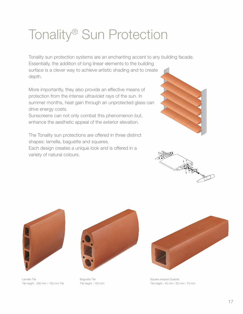
17
Tonality® Sun ProtectionTonality sun protection systems are an enchanting accent to any building facade.Essentially, the addition of long linear elements to the building surface is a clever way to achieve artistic shading and to create depth.
More importantly, they also provide an effective means of protection from the intense ultraviolet rays of the sun. In summer months, heat gain through an unprotected glass can drive energy costs.Sunscreens can not only combat this phenomenon but, enhance the aesthetic appeal of the exterior elevation.
The Tonality sun protections are offered in three distinct shapes: lamella, baguette and squares.Each design creates a unique look and is offered in a variety of natural colours.
Lamella Tile
Tile height : 260 mm / 150 mm Tile
Baguette Tile
Tile height : 150 mm
Square-shaped Quadrat
Tile height : 40 mm / 50 mm / 70 mm
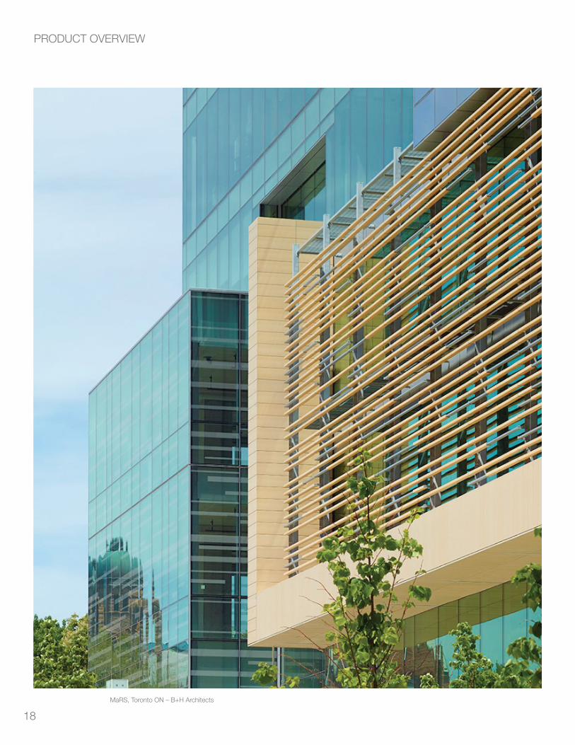
18
PRODUCT OVERVIEW
MaRS, Toronto ON – B+H Architects
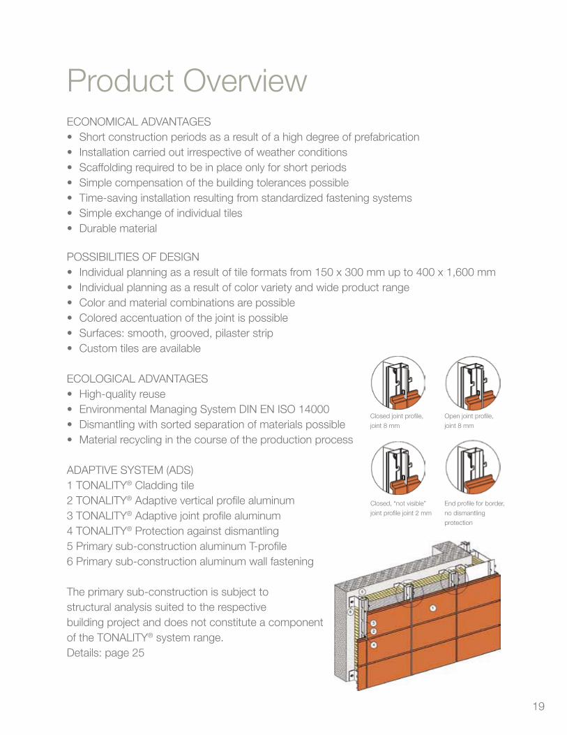
19
ECONOMICAL ADVANTAGES • Shortconstructionperiodsasaresultofahighdegreeofprefabrication• Installationcarriedoutirrespectiveofweatherconditions• Scaffoldingrequiredtobeinplaceonlyforshortperiods• Simplecompensationofthebuildingtolerancespossible• Time-savinginstallationresultingfromstandardizedfasteningsystems• Simpleexchangeofindividualtiles• Durablematerial
POSSIBILITIES OF DESIGN• Individualplanningasaresultoftileformatsfrom150x300mmupto400x1,600mm• Individualplanningasaresultofcolorvarietyandwideproductrange• Colorandmaterialcombinationsarepossible• Coloredaccentuationofthejointispossible• Surfaces:smooth,grooved,pilasterstrip• Customtilesareavailable
ECOLOGICAL ADVANTAGES• High-qualityreuse• EnvironmentalManagingSystemDINENISO14000• Dismantlingwithsortedseparationofmaterialspossible• Materialrecyclinginthecourseoftheproductionprocess
ADAPTIVE SYSTEM (ADS)1 TONALITY® Cladding tile2 TONALITY® Adaptive vertical profile aluminum3 TONALITY® Adaptive joint profile aluminum4 TONALITY® Protection against dismantling5 Primary sub-construction aluminum T-profile6 Primary sub-construction aluminum wall fastening
The primary sub-construction is subject tostructural analysis suited to the respectivebuilding project and does not constitute a componentof the TONALITY® system range.Details: page 25
Product Overview
Closed joint profile,
joint 8 mm
Open joint profile,
joint 8 mm
End profile for border,
no dismantling
protection
Closed, “not visible”
joint profile joint 2 mm
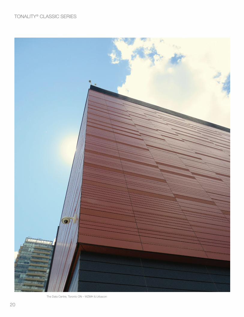
20
TONALITY® CLASSIC SERIES
The Data Centre, Toronto ON – WZMH & Urbacon
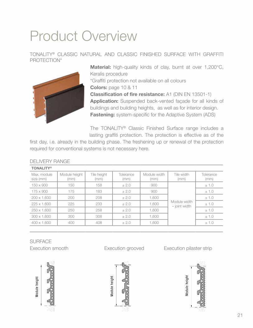
21
TONALITY® CLASSIC NATURAL AND CLASSIC FINISHED SURFACE WITH GRAFFITI PROTECTION*
Material: high-quality kinds of clay, burnt at over 1,200°C, Keralis procedure*Graffiti protection not available on all coloursColors: page 10 & 11Classification of fire resistance: A1 (DIN EN 13501-1)Application: Suspended back-vented façade for all kinds of buildings and building heights, as well as for interior design.Fastening: system-specific for the Adaptive System (ADS)
The TONALITY® Classic Finished Surface range includes a lasting graffiti protection. The protection is effective as of the
first day, i.e. already in the building phase. The freshening up or renewal of the protection required for conventional systems is not necessary here.
DELIVERY RANGETONALITY®
Max. module size (mm)
Module height(mm)
Tile height(mm)
Tolerance(mm)
Module width(mm)
Tile width(mm)
Tolerance(mm)
150 x 900 150 158 ± 2.0 900
Module width– joint width
± 1.0
175 x 900 175 183 ± 2.0 900 ± 1.0
200 x 1,600 200 208 ± 2.0 1,600 ± 1.0
225 x 1,600 225 233 ± 2.0 1,600 ± 1.0
250 x 1,600 250 258 ± 2.0 1,600 ± 1.0
300 x 1,600 300 308 ± 2.0 1,600 ± 1.0
400 x 1,600 400 408 ± 2.0 1,600 ± 1.0
SURFACEExecution smooth Execution grooved Execution pilaster strip
Product Overview

22
TONALITY® LAMELLE TILES
Kreiskrankenhaus in Buchen, Germany (foto Dietmar Strau SS, Besigheim )
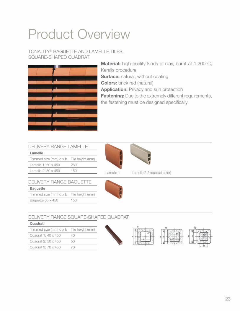
23
TONALITY® BAGUETTE AND LAMELLE TILES, SQUARE-SHAPED QUADRAT
Material: high-quality kinds of clay, burnt at 1,200°C, Keralis procedureSurface: natural, without coatingColors: brick red (natural)Application: Privacy and sun protectionFastening: Due to the extremely different requirements, the fastening must be designed specifically
DELIVERY RANGE LAMELLELamelle
Trimmed size (mm) d x b Tile height (mm)
Lamelle 1: 60 x 450 260
Lamelle 2: 50 x 450 150
DELIVERY RANGE BAGUETTEBaguette
Trimmed size (mm) d x b Tile height (mm)
Baguette 65 x 450 150
DELIVERY RANGE SQUARE-SHAPED QUADRATQuadrat
Trimmed size (mm) d x b Tile height (mm)
Quadrat 1: 40 x 450 40
Quadrat 2: 50 x 450 50
Quadrat 3: 70 x 450 70
Product Overview
Lamelle 1 Lamelle 2 2 (special color)
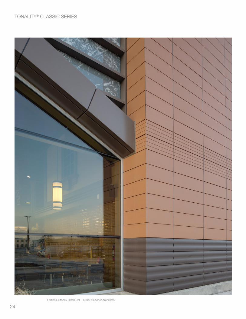
24
TONALITY® CLASSIC SERIES
Fortinos, Stoney Creek ON – Turner Fleischer Architects
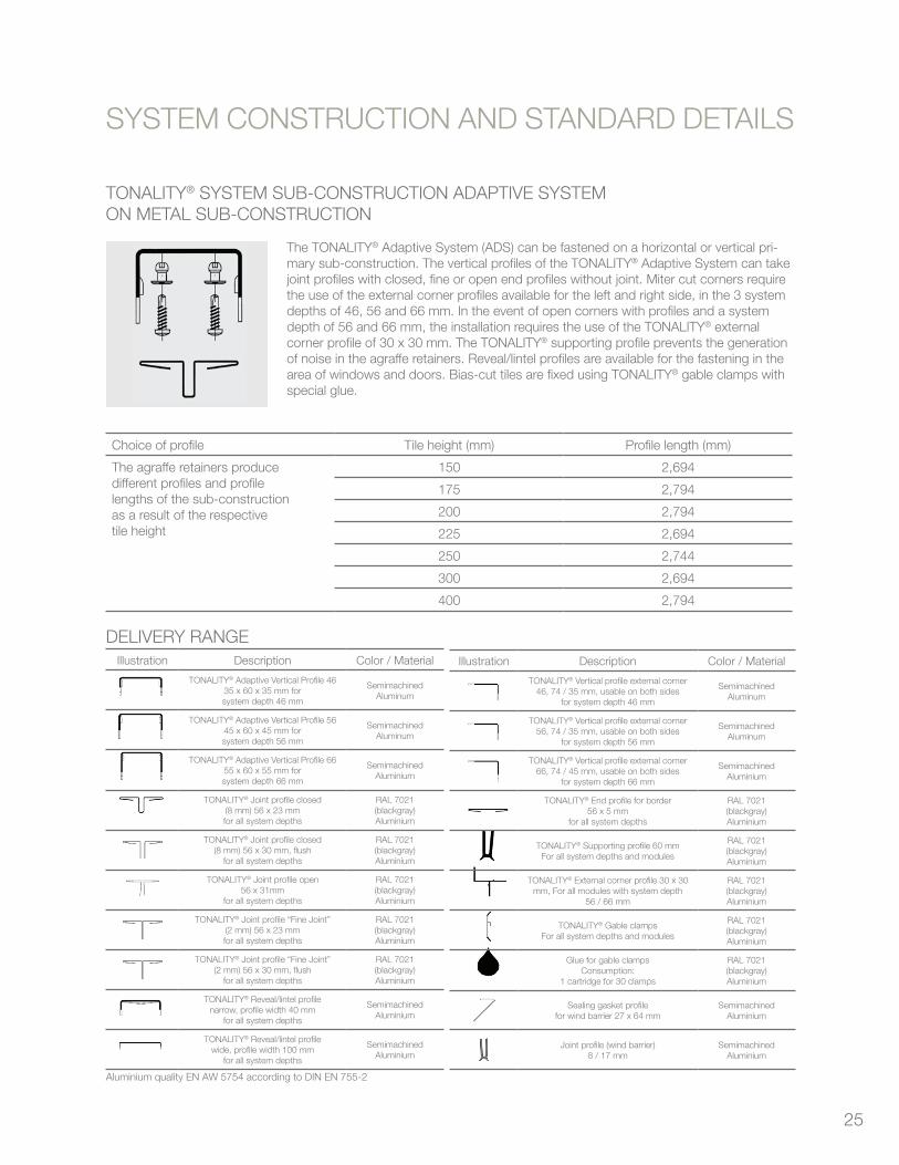
25
TONALITY® SYSTEM SUB-CONSTRUCTION ADAPTIVE SYSTEM ON METAL SUB-CONSTRUCTION
The TONALITY® Adaptive System (ADS) can be fastened on a horizontal or vertical pri-mary sub-construction. The vertical profiles of the TONALITY® Adaptive System can take joint profiles with closed, fine or open end profiles without joint. Miter cut corners require the use of the external corner profiles available for the left and right side, in the 3 system depths of 46, 56 and 66 mm. In the event of open corners with profiles and a system depth of 56 and 66 mm, the installation requires the use of the TONALITY® external corner profile of 30 x 30 mm. The TONALITY® supporting profile prevents the generation of noise in the agraffe retainers. Reveal/lintel profiles are available for the fastening in the area of windows and doors. Bias-cut tiles are fixed using TONALITY® gable clamps with special glue.
Choice of profile Tile height (mm) Profile length (mm)
The agraffe retainers producedifferent profiles and profilelengths of the sub-constructionas a result of the respectivetile height
150 2,694
175 2,794
200 2,794
225 2,694
250 2,744
300 2,694
400 2,794
DELIVERY RANGEIllustration Description Color / Material
TONALITY® Adaptive Vertical Profile 4635 x 60 x 35 mm forsystem depth 46 mm
SemimachinedAluminum
TONALITY® Adaptive Vertical Profile 5645 x 60 x 45 mm forsystem depth 56 mm
SemimachinedAluminum
TONALITY® Adaptive Vertical Profile 6655 x 60 x 55 mm forsystem depth 66 mm
SemimachinedAluminium
TONALITY® Joint profile closed(8 mm) 56 x 23 mmfor all system depths
RAL 7021(blackgray)Aluminium
TONALITY® Joint profile closed(8 mm) 56 x 30 mm, flush
for all system depths
RAL 7021(blackgray)Aluminium
TONALITY® Joint profile open56 x 31mm
for all system depths
RAL 7021(blackgray)Aluminium
TONALITY® Joint profile “Fine Joint”(2 mm) 56 x 23 mmfor all system depths
RAL 7021(blackgray)Aluminium
TONALITY® Joint profile “Fine Joint”(2 mm) 56 x 30 mm, flush
for all system depths
RAL 7021(blackgray)Aluminium
TONALITY® Reveal/lintel profilenarrow, profile width 40 mm
for all system depths
SemimachinedAluminium
TONALITY® Reveal/lintel profilewide, profile width 100 mm
for all system depths
SemimachinedAluminium
SYSTEM CONSTRUCTION AND STANDARD DETAILS
Illustration Description Color / Material
TONALITY® Vertical profile external corner46, 74 / 35 mm, usable on both sides
for system depth 46 mm
SemimachinedAluminum
TONALITY® Vertical profile external corner56, 74 / 35 mm, usable on both sides
for system depth 56 mm
SemimachinedAluminum
TONALITY® Vertical profile external corner66, 74 / 45 mm, usable on both sides
for system depth 66 mm
SemimachinedAluminium
TONALITY® End profile for border56 x 5 mm
for all system depths
RAL 7021(blackgray)Aluminium
TONALITY® Supporting profile 60 mmFor all system depths and modules
RAL 7021(blackgray)Aluminium
TONALITY® External corner profile 30 x 30mm, For all modules with system depth
56 / 66 mm
RAL 7021(blackgray)Aluminium
TONALITY® Gable clampsFor all system depths and modules
RAL 7021(blackgray)Aluminium
Glue for gable clampsConsumption:
1 cartridge for 30 clamps
RAL 7021(blackgray)Aluminium
Sealing gasket profilefor wind barrier 27 x 64 mm
SemimachinedAluminium
Joint profile (wind barrier)8 / 17 mm
SemimachinedAluminium
Aluminium quality EN AW 5754 according to DIN EN 755-2
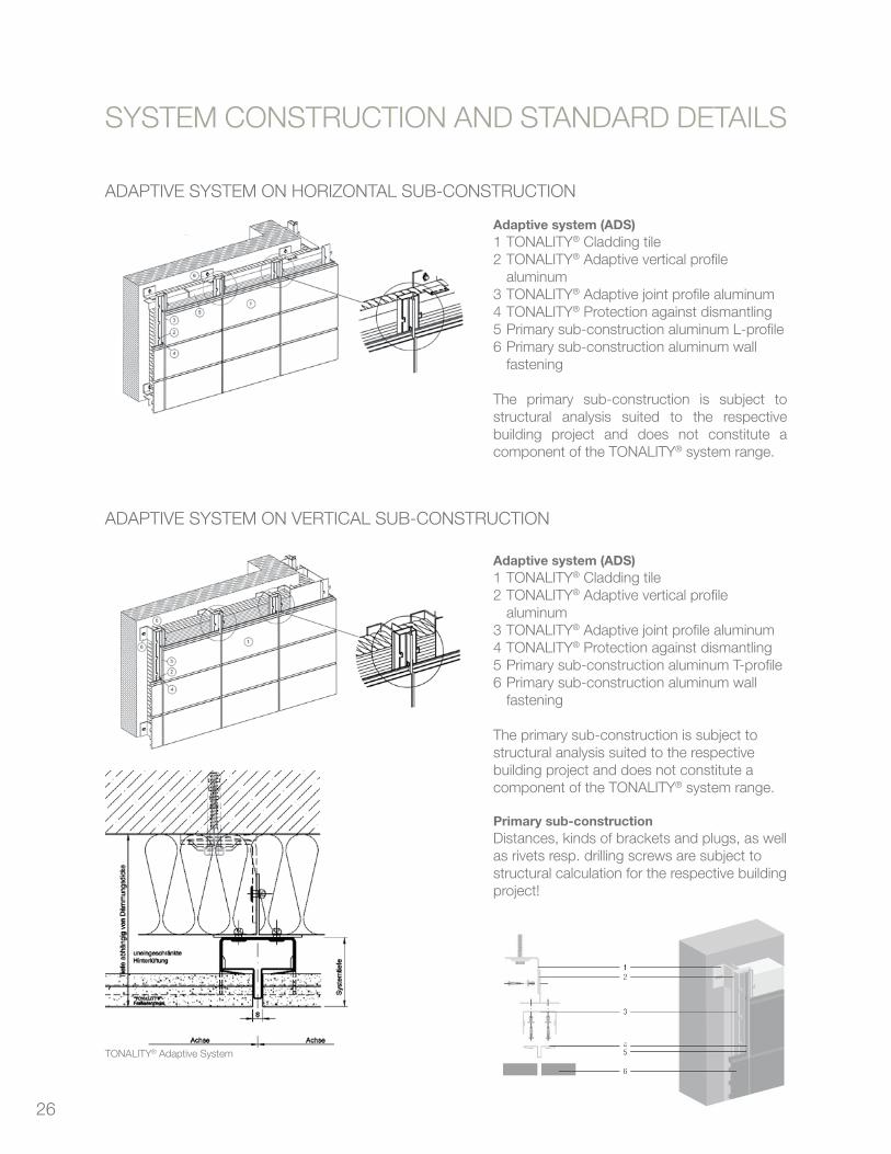
26
ADAPTIVE SYSTEM ON HORIZONTAL SUB-CONSTRUCTION
ADAPTIVE SYSTEM ON VERTICAL SUB-CONSTRUCTION
SYSTEM CONSTRUCTION AND STANDARD DETAILS
Adaptive system (ADS)1 TONALITY® Cladding tile2 TONALITY® Adaptive vertical profile
aluminum3 TONALITY® Adaptive joint profile aluminum4 TONALITY® Protection against dismantling5 Primary sub-construction aluminum L-profile6 Primary sub-construction aluminum wall
fastening
The primary sub-construction is subject to structural analysis suited to the respective building project and does not constitute a component of the TONALITY® system range.
Adaptive system (ADS)1 TONALITY® Cladding tile2 TONALITY® Adaptive vertical profile
aluminum3 TONALITY® Adaptive joint profile aluminum4 TONALITY® Protection against dismantling5 Primary sub-construction aluminum T-profile6 Primary sub-construction aluminum wall
fastening
The primary sub-construction is subject to structural analysis suited to the respective building project and does not constitute a component of the TONALITY® system range.
Primary sub-constructionDistances, kinds of brackets and plugs, as well as rivets resp. drilling screws are subject to structural calculation for the respective building project!
TONALITY® Adaptive System
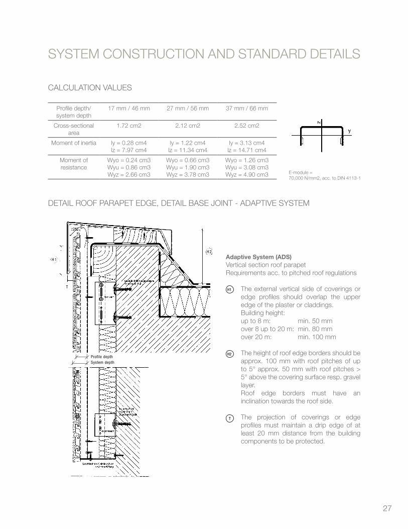
27
CALCULATION VALUES
Profile depth/system depth
17 mm / 46 mm 27 mm / 56 mm 37 mm / 66 mm
Cross-sectional area
1.72 cm2 2.12 cm2 2.52 cm2
Moment of inertia ly = 0.28 cm4lz = 7.97 cm4
ly = 1.22 cm4lz = 11.34 cm4
ly = 3.13 cm4lz = 14.71 cm4
Moment of resistance
Wyo = 0.24 cm3Wyu = 0.86 cm3Wyz = 2.66 cm3
Wyo = 0.66 cm3Wyu = 1.90 cm3Wyz = 3.78 cm3
Wyo = 1.26 cm3Wyu = 3.08 cm3Wyz = 4.90 cm3
DETAIL ROOF PARAPET EDGE, DETAIL BASE JOINT - ADAPTIVE SYSTEM
SYSTEM CONSTRUCTION AND STANDARD DETAILS
Adaptive System (ADS)Vertical section roof parapetRequirements acc. to pitched roof regulations
The external vertical side of coverings or edge profiles should overlap the upper edge of the plaster or claddings.Building height:up to 8 m: min. 50 mmover 8 up to 20 m: min. 80 mmover 20 m: min. 100 mm
The height of roof edge borders should be approx. 100 mm with roof pitches of up to 5° approx. 50 mm with roof pitches > 5° above the covering surface resp. gravel layer.Roof edge borders must have an inclination towards the roof side.
The projection of coverings or edge profiles must maintain a drip edge of at least 20 mm distance from the building components to be protected.
18 Cladding tile tonality®
SYSTEMCONSTRUCTIONANDSTANDARDDETAILS
Adaptive System (ADS)Vertical section roof parapetRequirements acc. to pitched roof regulations
The external vertical side of coverings oredge profiles should overlap the upperedge of the plaster or claddings.Building height:up to 8 m: min. 50 mmover 8 up to 20 m: min. 80 mmover 20 m: min. 100 mm
The height of roof edge borders should beapprox. 100 mm with roof pitches of up to 5°approx. 50 mm with roof pitches > 5°above the covering surface resp. gravellayer.Roof edge borders must have an inclina-tion towards the roof side. The projection of coverings or edge pro-files must maintain a drip edge of at least20 mm distance from the building compo-nents to be protected.
Detail Roof Parapet Edge, Detail Base Joint - Adaptive System
SYSTEM CONSTRUCTION AND STANDARD DETAILS
H 1
H 1
H 2
H 2
T
T
Maßstab ca. 1:10
Calculation valuesProfile depth/system depth
Cross-sectional area
Moment of inertia
Moment of resistance
17 mm / 46 mm
1.72 cm2
ly = 0.28 cm4
lz = 7.97 cm4
Wyo = 0.24 cm3
Wyu = 0.86 cm3
Wyz = 2.66 cm3
27 mm / 56 mm
2.12 cm2
ly = 1.22 cm4
lz = 11.34 cm4
Wyo = 0.66 cm3
Wyu = 1.90 cm3
Wyz = 3.78 cm3
37 mm / 66 mm
2.52 cm2
ly = 3.13 cm4
lz = 14.71 cm4
Wyo = 1.26 cm3
Wyu = 3.08 cm3
Wyz = 4.90 cm3
E-module = 70,000 N/mm2, acc. to DIN 4113-1
Profile depth System depth
18Planning & Application 2009 Cladding tiles TONALITY®
TonalityWafu_GB_2009-2.qxp:Tonality_2009 04.08.2009 8:01 Uhr Seite 18
SYSTEM CONSTRUCTION AND STANDARD DETAILS
External corner 90° - TONALITY® on vertical pri-mary sub-construction.A) External corner: TONALITY® with miter cut
– Vertical profile external corner 45 x 74– Supporting profile
In case of miter cut, the edges must have abevel of 4 mm. The fixation of the vertical pro-file is effected on an aluminum bracket.B) External corner: TONALITY® with corner pro-
file– Vertical profile external corner 45 x 74– Supporting profile– Visible external corner profile
The fixation of the vertical profile is effected onan aluminum bracket.
Detail External Corner of Building – Adaptive System on Vertical Sub-Construction
Detail External Corner of Building – Adaptive System on Horizontal Sub-Construction
A B
C D E
Detail Internal Corner of Building – Adaptive System
Internal corner 90° with adaptive system end profile
External corner 90° - TONALITY® on horizontalprimary sub-construction.C) External corner: TONALITY® with miter cut
– Vertical profile external corner 45 x 74– Supporting profile
In case of miter cut, the edges must have abevel of 4 mm.D) External corner: TONALITY® with corner profile
– Vertical profile external corner 45 x 74– Supporting profile– Visible external corner profile (anodized
E6EV1 / semimachined)
E) External corner: TONALITY® with verticalwind barrier for reduced wind pressureaccording to DIN 1055-4:2005-03
19Planning & Application 2009 Cladding tiles TONALITY®
TonalityWafu_GB_2009-2.qxp:Tonality_2009 04.08.2009 8:01 Uhr Seite 19
H1
H2
T
E-module = 70,000 N/mm2, acc. to DIN 4113-1
18 Cladding tile tonality®
SYSTEMCONSTRUCTIONANDSTANDARDDETAILS
Adaptive System (ADS)Vertical section roof parapetRequirements acc. to pitched roof regulations
The external vertical side of coverings oredge profiles should overlap the upperedge of the plaster or claddings.Building height:up to 8 m: min. 50 mmover 8 up to 20 m: min. 80 mmover 20 m: min. 100 mm
The height of roof edge borders should beapprox. 100 mm with roof pitches of up to 5°approx. 50 mm with roof pitches > 5°above the covering surface resp. gravellayer.Roof edge borders must have an inclina-tion towards the roof side. The projection of coverings or edge pro-files must maintain a drip edge of at least20 mm distance from the building compo-nents to be protected.
Detail Roof Parapet Edge, Detail Base Joint - Adaptive System
SYSTEM CONSTRUCTION AND STANDARD DETAILS
H 1
H 1
H 2
H 2
T
T
Maßstab ca. 1:10
Calculation valuesProfile depth/system depth
Cross-sectional area
Moment of inertia
Moment of resistance
17 mm / 46 mm
1.72 cm2
ly = 0.28 cm4
lz = 7.97 cm4
Wyo = 0.24 cm3
Wyu = 0.86 cm3
Wyz = 2.66 cm3
27 mm / 56 mm
2.12 cm2
ly = 1.22 cm4
lz = 11.34 cm4
Wyo = 0.66 cm3
Wyu = 1.90 cm3
Wyz = 3.78 cm3
37 mm / 66 mm
2.52 cm2
ly = 3.13 cm4
lz = 14.71 cm4
Wyo = 1.26 cm3
Wyu = 3.08 cm3
Wyz = 4.90 cm3
E-module = 70,000 N/mm2, acc. to DIN 4113-1
Profile depth System depth
18Planning & Application 2009 Cladding tiles TONALITY®
TonalityWafu_GB_2009-2.qxp:Tonality_2009 04.08.2009 8:01 Uhr Seite 18
SYSTEM CONSTRUCTION AND STANDARD DETAILS
External corner 90° - TONALITY® on vertical pri-mary sub-construction.A) External corner: TONALITY® with miter cut
– Vertical profile external corner 45 x 74– Supporting profile
In case of miter cut, the edges must have abevel of 4 mm. The fixation of the vertical pro-file is effected on an aluminum bracket.B) External corner: TONALITY® with corner pro-
file– Vertical profile external corner 45 x 74– Supporting profile– Visible external corner profile
The fixation of the vertical profile is effected onan aluminum bracket.
Detail External Corner of Building – Adaptive System on Vertical Sub-Construction
Detail External Corner of Building – Adaptive System on Horizontal Sub-Construction
A B
C D E
Detail Internal Corner of Building – Adaptive System
Internal corner 90° with adaptive system end profile
External corner 90° - TONALITY® on horizontalprimary sub-construction.C) External corner: TONALITY® with miter cut
– Vertical profile external corner 45 x 74– Supporting profile
In case of miter cut, the edges must have abevel of 4 mm.D) External corner: TONALITY® with corner profile
– Vertical profile external corner 45 x 74– Supporting profile– Visible external corner profile (anodized
E6EV1 / semimachined)
E) External corner: TONALITY® with verticalwind barrier for reduced wind pressureaccording to DIN 1055-4:2005-03
19Planning & Application 2009 Cladding tiles TONALITY®
TonalityWafu_GB_2009-2.qxp:Tonality_2009 04.08.2009 8:01 Uhr Seite 19
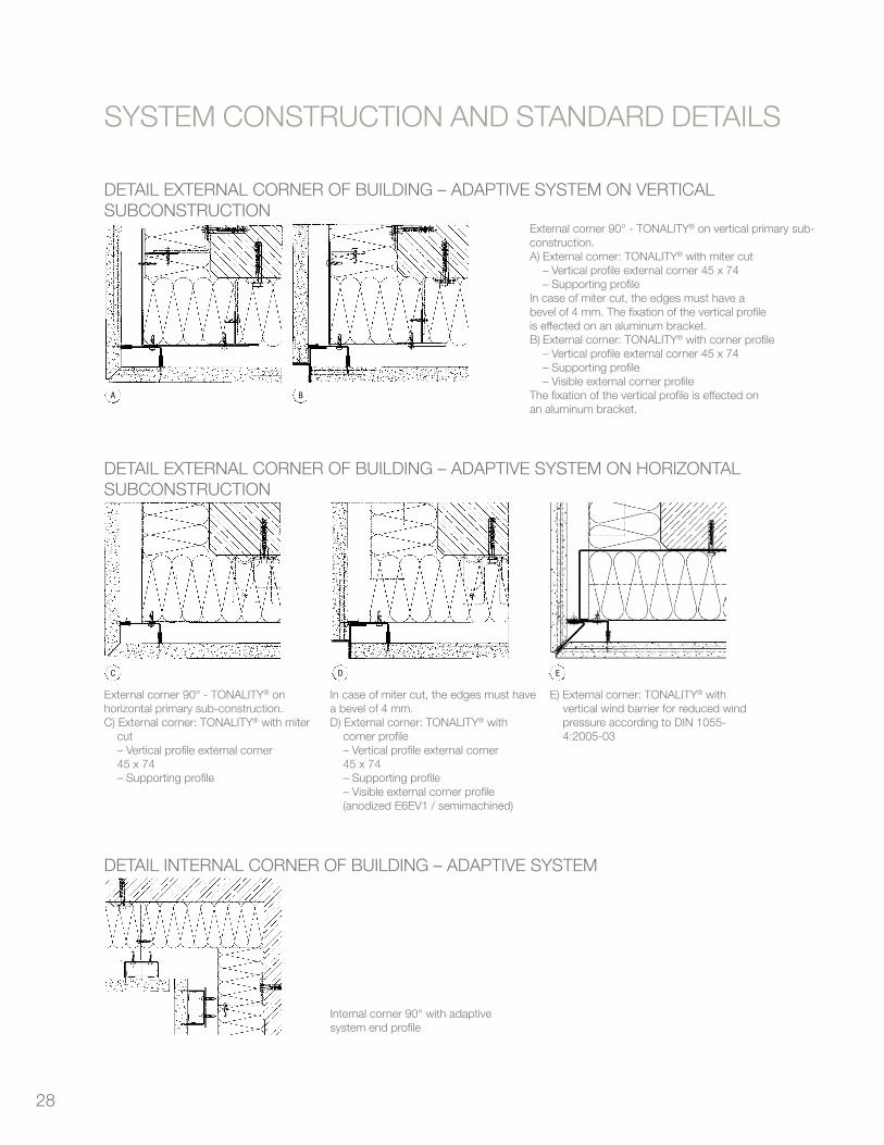
28
DETAIL ExTERNAL CORNER OF BUILDING – ADAPTIVE SYSTEM ON VERTICAL SUBCONSTRUCTION
Cladding tile tonality® 19
SYSTEMCONSTRUCTIONANDSTANDARDDETAILSSYSTEM CONSTRUCTION AND STANDARD DETAILS
External corner 90° - TONALITY® on vertical pri-mary sub-construction.A) External corner: TONALITY® with miter cut
– Vertical profile external corner 45 x 74– Supporting profile
In case of miter cut, the edges must have abevel of 4 mm. The fixation of the vertical pro-file is effected on an aluminum bracket.B) External corner: TONALITY® with corner pro-
file– Vertical profile external corner 45 x 74– Supporting profile– Visible external corner profile
The fixation of the vertical profile is effected onan aluminum bracket.
Detail External Corner of Building – Adaptive System on Vertical Sub-Construction
Detail External Corner of Building – Adaptive System on Horizontal Sub-Construction
A B
C D E
Detail Internal Corner of Building – Adaptive System
Internal corner 90° with adaptive system end profile
External corner 90° - TONALITY® on horizontalprimary sub-construction.C) External corner: TONALITY® with miter cut
– Vertical profile external corner 45 x 74– Supporting profile
In case of miter cut, the edges must have abevel of 4 mm.D) External corner: TONALITY® with corner profile
– Vertical profile external corner 45 x 74– Supporting profile– Visible external corner profile (anodized
E6EV1 / semimachined)
E) External corner: TONALITY® with verticalwind barrier for reduced wind pressureaccording to DIN 1055-4:2005-03
19Planning & Application 2009 Cladding tiles TONALITY®
TonalityWafu_GB_2009-2.qxp:Tonality_2009 04.08.2009 8:01 Uhr Seite 19
DETAIL ExTERNAL CORNER OF BUILDING – ADAPTIVE SYSTEM ON HORIZONTAL SUBCONSTRUCTION
Cladding tile tonality® 19
SYSTEMCONSTRUCTIONANDSTANDARDDETAILSSYSTEM CONSTRUCTION AND STANDARD DETAILS
External corner 90° - TONALITY® on vertical pri-mary sub-construction.A) External corner: TONALITY® with miter cut
– Vertical profile external corner 45 x 74– Supporting profile
In case of miter cut, the edges must have abevel of 4 mm. The fixation of the vertical pro-file is effected on an aluminum bracket.B) External corner: TONALITY® with corner pro-
file– Vertical profile external corner 45 x 74– Supporting profile– Visible external corner profile
The fixation of the vertical profile is effected onan aluminum bracket.
Detail External Corner of Building – Adaptive System on Vertical Sub-Construction
Detail External Corner of Building – Adaptive System on Horizontal Sub-Construction
A B
C D E
Detail Internal Corner of Building – Adaptive System
Internal corner 90° with adaptive system end profile
External corner 90° - TONALITY® on horizontalprimary sub-construction.C) External corner: TONALITY® with miter cut
– Vertical profile external corner 45 x 74– Supporting profile
In case of miter cut, the edges must have abevel of 4 mm.D) External corner: TONALITY® with corner profile
– Vertical profile external corner 45 x 74– Supporting profile– Visible external corner profile (anodized
E6EV1 / semimachined)
E) External corner: TONALITY® with verticalwind barrier for reduced wind pressureaccording to DIN 1055-4:2005-03
19Planning & Application 2009 Cladding tiles TONALITY®
TonalityWafu_GB_2009-2.qxp:Tonality_2009 04.08.2009 8:01 Uhr Seite 19
DETAIL INTERNAL CORNER OF BUILDING – ADAPTIVE SYSTEM
Cladding tile tonality® 19
SYSTEMCONSTRUCTIONANDSTANDARDDETAILSSYSTEM CONSTRUCTION AND STANDARD DETAILS
External corner 90° - TONALITY® on vertical pri-mary sub-construction.A) External corner: TONALITY® with miter cut
– Vertical profile external corner 45 x 74– Supporting profile
In case of miter cut, the edges must have abevel of 4 mm. The fixation of the vertical pro-file is effected on an aluminum bracket.B) External corner: TONALITY® with corner pro-
file– Vertical profile external corner 45 x 74– Supporting profile– Visible external corner profile
The fixation of the vertical profile is effected onan aluminum bracket.
Detail External Corner of Building – Adaptive System on Vertical Sub-Construction
Detail External Corner of Building – Adaptive System on Horizontal Sub-Construction
A B
C D E
Detail Internal Corner of Building – Adaptive System
Internal corner 90° with adaptive system end profile
External corner 90° - TONALITY® on horizontalprimary sub-construction.C) External corner: TONALITY® with miter cut
– Vertical profile external corner 45 x 74– Supporting profile
In case of miter cut, the edges must have abevel of 4 mm.D) External corner: TONALITY® with corner profile
– Vertical profile external corner 45 x 74– Supporting profile– Visible external corner profile (anodized
E6EV1 / semimachined)
E) External corner: TONALITY® with verticalwind barrier for reduced wind pressureaccording to DIN 1055-4:2005-03
19Planning & Application 2009 Cladding tiles TONALITY®
TonalityWafu_GB_2009-2.qxp:Tonality_2009 04.08.2009 8:01 Uhr Seite 19
SYSTEM CONSTRUCTION AND STANDARD DETAILS
External corner 90° - TONALITY® on vertical primary sub-construction.A) External corner: TONALITY® with miter cut – Vertical profile external corner 45 x 74 – Supporting profileIn case of miter cut, the edges must have abevel of 4 mm. The fixation of the vertical profileis effected on an aluminum bracket.B) External corner: TONALITY® with corner profile – Vertical profile external corner 45 x 74 – Supporting profile – Visible external corner profileThe fixation of the vertical profile is effected onan aluminum bracket.
External corner 90° - TONALITY® on horizontal primary sub-construction.C) External corner: TONALITY® with miter
cut – Vertical profile external corner
45 x 74 – Supporting profile
In case of miter cut, the edges must have a bevel of 4 mm.D) External corner: TONALITY® with
corner profile – Vertical profile external corner
45 x 74 – Supporting profile – Visible external corner profile
(anodized E6EV1 / semimachined)
Internal corner 90° with adaptivesystem end profile
E) External corner: TONALITY® with vertical wind barrier for reduced wind pressure according to DIN 1055-4:2005-03

29
DETAIL WINDOW – ADAPTIVE SYSTEM
20 Cladding tile tonality®
SYSTEMCONSTRUCTIONANDSTANDARDDETAILS
Detail Window – Adaptive System
SYSTEM CONSTRUCTION AND STANDARD DETAILS
Vertical sectionWindow, lintel and parapet
A) without sun protection
B) with integrated sun protection
C) parapet of cladding tiles
Maßstab ca. 1:5
Horizontal sectionWindow reveal with vertical primary sub-con-struction.
Horizontal sectionWindow reveal with horizontal primary sub-con-struction.
Horizontal sectionWindow reveal of cladding tiles with revealclamp.Tile length up to max. 150 mm.
Horizontal sectionWindow reveal of cladding tiles with reveal /lintel profile on vertical primary sub-construc-tion.
A
B C
20Planning & Application 2009 Cladding tiles TONALITY®
TonalityWafu_GB_2009-2.qxp:Tonality_2009 04.08.2009 8:01 Uhr Seite 20
SYSTEM CONSTRUCTION AND STANDARD DETAILS
Vertical sectionWindow, lintel and parapet
A) without sun protection
B) with integrated sun protection
C) parapet of cladding tiles
Horizontal sectionWindow reveal with vertical primary sub-construction.
Horizontal sectionWindow reveal with horizontal primary sub-construction.
Horizontal sectionWindow reveal of cladding tiles with revealclamp.Tile length up to max. 150 mm.
Horizontal sectionWindow reveal of cladding tiles with reveal /lintel profile on vertical primary sub-construction
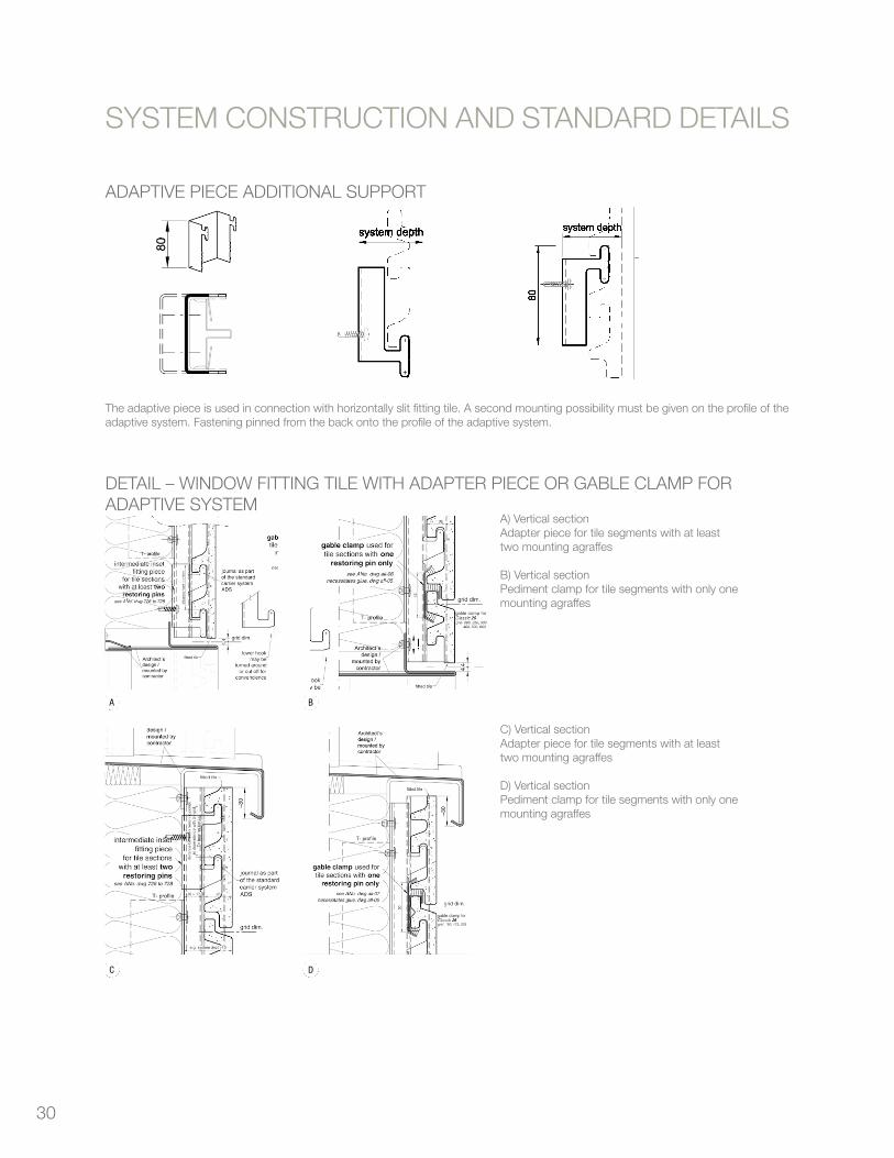
30
ADAPTIVE PIECE ADDITIONAL SUPPORT
Cladding tile tonality® 21
SYSTEMCONSTRUCTIONANDSTANDARDDETAILS
Detail Window – Adaptive System
SYSTEM CONSTRUCTION AND STANDARD DETAILS
Vertical sectionWindow, lintel and parapet
A) without sun protection
B) with integrated sun protection
C) parapet of cladding tiles
Maßstab ca. 1:5
Horizontal sectionWindow reveal with vertical primary sub-con-struction.
Horizontal sectionWindow reveal with horizontal primary sub-con-struction.
Horizontal sectionWindow reveal of cladding tiles with revealclamp.Tile length up to max. 150 mm.
Horizontal sectionWindow reveal of cladding tiles with reveal /lintel profile on vertical primary sub-construc-tion.
A
B C
20Planning & Application 2009 Cladding tiles TONALITY®
TonalityWafu_GB_2009-2.qxp:Tonality_2009 04.08.2009 8:01 Uhr Seite 20
Detail – Window Fitting Tile with Adapter Piece or Gable Clamp for Adaptive System
Adaptive Piece Additional Support
SYSTEM CONSTRUCTION AND STANDARD DETAILS
A B
C D
A) Vertical sectionAdapter piece for tile segments with at leasttwo mounting agraffes
B) Vertical sectionPediment clamp for tile segments with only onemounting agraffes
C) Vertical sectionAdapter piece for tile segments with at leasttwo mounting agraffes
D) Vertical sectionPediment clamp for tile segments with only onemounting agraffes
The adaptive piece is used in connection with horizontally slit fitting tile. A second mounting possibility must be given on the profile of the adaptivesystem. Fastening pinned from the back onto the profile of the adaptive system.
21Planning & Application 2009 Cladding tiles TONALITY®
TonalityWafu_GB_2009-2.qxp:Tonality_2009 04.08.2009 8:01 Uhr Seite 21
The adaptive piece is used in connection with horizontally slit fitting tile. A second mounting possibility must be given on the profile of the adaptive system. Fastening pinned from the back onto the profile of the adaptive system.
DETAIL – WINDOW FITTING TILE WITH ADAPTER PIECE OR GABLE CLAMP FOR ADAPTIVE SYSTEM
Cladding tile tonality® 21
SYSTEMCONSTRUCTIONANDSTANDARDDETAILS
Detail Window – Adaptive System
SYSTEM CONSTRUCTION AND STANDARD DETAILS
Vertical sectionWindow, lintel and parapet
A) without sun protection
B) with integrated sun protection
C) parapet of cladding tiles
Maßstab ca. 1:5
Horizontal sectionWindow reveal with vertical primary sub-con-struction.
Horizontal sectionWindow reveal with horizontal primary sub-con-struction.
Horizontal sectionWindow reveal of cladding tiles with revealclamp.Tile length up to max. 150 mm.
Horizontal sectionWindow reveal of cladding tiles with reveal /lintel profile on vertical primary sub-construc-tion.
A
B C
20Planning & Application 2009 Cladding tiles TONALITY®
TonalityWafu_GB_2009-2.qxp:Tonality_2009 04.08.2009 8:01 Uhr Seite 20
Detail – Window Fitting Tile with Adapter Piece or Gable Clamp for Adaptive System
Adaptive Piece Additional Support
SYSTEM CONSTRUCTION AND STANDARD DETAILS
A B
C D
A) Vertical sectionAdapter piece for tile segments with at leasttwo mounting agraffes
B) Vertical sectionPediment clamp for tile segments with only onemounting agraffes
C) Vertical sectionAdapter piece for tile segments with at leasttwo mounting agraffes
D) Vertical sectionPediment clamp for tile segments with only onemounting agraffes
The adaptive piece is used in connection with horizontally slit fitting tile. A second mounting possibility must be given on the profile of the adaptivesystem. Fastening pinned from the back onto the profile of the adaptive system.
21Planning & Application 2009 Cladding tiles TONALITY®
TonalityWafu_GB_2009-2.qxp:Tonality_2009 04.08.2009 8:01 Uhr Seite 21SYSTEM CONSTRUCTION AND STANDARD DETAILS
A) Vertical sectionAdapter piece for tile segments with at leasttwo mounting agraffes
B) Vertical sectionPediment clamp for tile segments with only onemounting agraffes
C) Vertical sectionAdapter piece for tile segments with at leasttwo mounting agraffes
D) Vertical sectionPediment clamp for tile segments with only onemounting agraffes

31
TONALITY SYSTEM SUB-CONSTRUCTION OF ADAPTIVE SYSTEM ON WOODEN SUB-CONSTRUCTION
32 Cladding tile tonality®
SYSTEMCONSTRUCTIONANDSTANDARDDETAILS
SYSTEM CONSTRUCTION AND STANDARD DETAILS
TONALITY® System Sub-Construction of Adaptive, Base Clinch Rail and Classic Profile Systemson Wooden Primary Sub-Construction
1
2
3
4
5
System structure of the Adaptive System
Adaptive System on horizontal wooden sub-construction
Base Clinch Rail Profile on vertical wooden sub-construction
1 Wooden sub-construction2 Vertical profile of the TONALITY® Adaptive
System3 Rivet / drilling screw / woodscrew4 Joint profile of TONALITY® Adaptive System5 TONALITY® Cladding tile
1
2
3
4
1
2
3
5
4
System structure of the Base Clinch Rail System
System structure of the Classic Profile System
1 Wooden sub-construction2 Profile of the TONALITY® Base Clinch Rail
System3 Rivet / drilling screw / woodscrew4 TONALITY® Cladding tile
1 Wooden sub-construction2 Profile of the TONALITY® Classic Profile
System3 Rivet / drilling screw / woodscrew4 TONALITY® Cladding tile5 Joint profile of the Classic Profile System
32Planning & Application 2009 Cladding tiles TONALITY®
The installation of the Classic Profile System on a wooden sub-construction is possible as well.
TonalityWafu_GB_2009-2.qxp:Tonality_2009 04.08.2009 8:02 Uhr Seite 32
Adaptive System on horizontal wooden sub-construction
Detail Internal Corner of Building – Wooden Primary Sub-Construction
Cladding tile tonality® 33
SYSTEMCONSTRUCTIONANDSTANDARDDETAILSSYSTEM CONSTRUCTION AND STANDARD DETAILS
Detail External Corner of Building – Wooden Primary Sub-Construction
Horizontal sectionExternal corner with external corner profile
Horizontal sectionExternal corner with miter cut
Detail Internal Corner of Building – Wooden Primary Sub-Construction
Horizontal sectionInternal corner
Detail Window – Wooden Primary Sub-Construction
Horizontal sectionWindow reveal with metal frame on wooden sub-construction
Vertical sectionWindow sill connection onwooden sub-construction
30
33Planning & Application 2009 Cladding tiles TONALITY®
wooden substructure 80x60insolation 60 mm
wooden substructure 80x60
TONALITY cladding element
vertical profil for external corner
done byinstaller
not restriced ventilation
TonalityWafu_GB_2009-2.qxp:Tonality_2009 04.08.2009 8:02 Uhr Seite 33
Detail Window – Wooden Primary Sub-Construction
Cladding tile tonality® 33
SYSTEMCONSTRUCTIONANDSTANDARDDETAILSSYSTEM CONSTRUCTION AND STANDARD DETAILS
Detail External Corner of Building – Wooden Primary Sub-Construction
Horizontal sectionExternal corner with external corner profile
Horizontal sectionExternal corner with miter cut
Detail Internal Corner of Building – Wooden Primary Sub-Construction
Horizontal sectionInternal corner
Detail Window – Wooden Primary Sub-Construction
Horizontal sectionWindow reveal with metal frame on wooden sub-construction
Vertical sectionWindow sill connection onwooden sub-construction
30
33Planning & Application 2009 Cladding tiles TONALITY®
wooden substructure 80x60insolation 60 mm
wooden substructure 80x60
TONALITY cladding element
vertical profil for external corner
done byinstaller
not restriced ventilation
TonalityWafu_GB_2009-2.qxp:Tonality_2009 04.08.2009 8:02 Uhr Seite 33
SYSTEM CONSTRUCTION AND STANDARD DETAILS
System structure of the Adaptive System1 Wooden sub-construction2 Vertical profile of the TONALITY® Adaptive System3 Rivet / drilling screw / woodscrew4 Joint profile of TONALITY® Adaptive System5 TONALITY® Cladding tile
Horizontal sectionInternal corner
Horizontal sectionWindow reveal with metal frame onwooden sub-construction
Vertical sectionWindow sill connection onwooden sub-construction
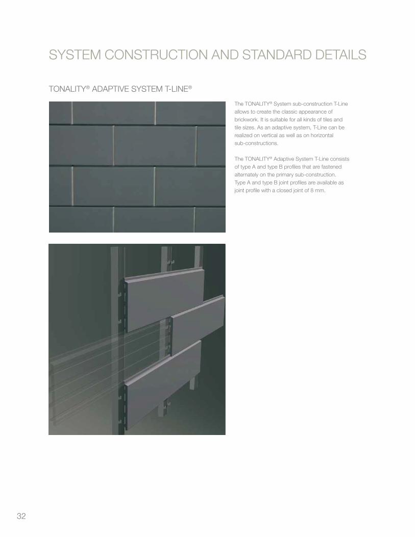
32
TONALITY® ADAPTIVE SYSTEM T-LINE®
SYSTEM CONSTRUCTION AND STANDARD DETAILS
The TONALITY® System sub-construction T-Lineallows to create the classic appearance ofbrickwork. It is suitable for all kinds of tiles andtile sizes. As an adaptive system, T-Line can berealized on vertical as well as on horizontalsub-constructions.
The TONALITY® Adaptive System T-Line consistsof type A and type B profiles that are fastenedalternately on the primary sub-construction.Type A and type B joint profiles are available asjoint profile with a closed joint of 8 mm.
34 Cladding tile tonality®
SYSTEMCONSTRUCTIONANDSTANDARDDETAILSSYSTEM CONSTRUCTION AND STANDARD DETAILS
TONALITY® Adaptive System T-Line®
The TONALITY® System sub-construction T-Lineallows to create the classic appearance ofbrickwork. It is suitable for all kinds of tiles andtile sizes. As an adaptive system, T-Line can berealized on vertical as well as on horizontalsub-constructions.
The TONALITY® Adaptive System T-Line consistsof type A and type B profiles that are fastenedalternately on the primary sub-construction.Type A and type B joint profiles are available asjoint profile with a closed joint of 8 mm.
34Planning & Application 2009 Cladding tiles TONALITY®
TonalityWafu_GB_2009-2.qxp:Tonality_2009 04.08.2009 8:02 Uhr Seite 34
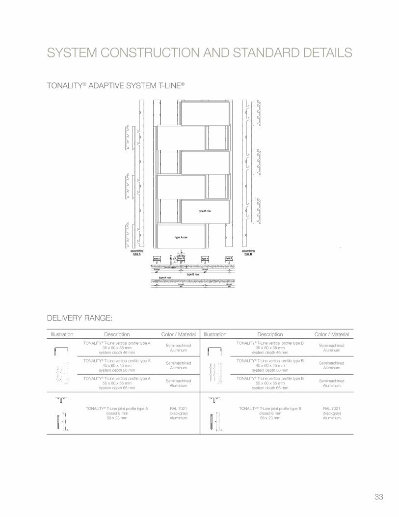
33
TONALITY® ADAPTIVE SYSTEM T-LINE®
Cladding tile tonality® 35
SYSTEMCONSTRUCTIONANDSTANDARDDETAILS
TONALITY® Adaptive System T-Line
SYSTEM CONSTRUCTION AND STANDARD DETAILS
Delivery range: Illustration Description
TONALITY® T-Line vertical profile type A35 x 60 x 35 mm
system depth 46 mm
TONALITY® T-Line vertical profile type A45 x 60 x 45 mm
system depth 56 mm
TONALITY® T-Line vertical profile type A55 x 60 x 55 mm
system depth 66 mm
TONALITY® T-Line joint profile type Aclosed 8 mm56 x 23 mm
Color / Material
SemimachinedAluminium
SemimachinedAluminium
SemimachinedAluminium
RAL 7021(blackgray)Aluminium
Illustration Description
TONALITY® T-Line vertical profile type B35 x 60 x 35 mm
system depth 46 mm
TONALITY® T-Line vertical profile type B45 x 60 x 45 mm
system depth 56 mm
TONALITY® T-Line vertical profile type B55 x 60 x 55 mm
system depth 66 mm
TONALITY® T-Line joint profile type Bclosed 8 mm56 x 23 mm
Color / Material
SemimachinedAluminium
SemimachinedAluminium
SemimachinedAluminium
RAL 7021(blackgray)Aluminium
Aluminium quality = EN AW 5754 according to DIN EN 755-2
35Planning & Application 2009 Cladding tiles TONALITY®
TonalityWafu_GB_2009-2.qxp:Tonality_2009 04.08.2009 8:02 Uhr Seite 35
DELIVERY RANGE:
SYSTEM CONSTRUCTION AND STANDARD DETAILS
Illustration Description Color / Material
TONALITY® T-Line vertical profile type A35 x 60 x 35 mm
system depth 46 mm
SemimachinedAluminum
TONALITY® T-Line vertical profile type A45 x 60 x 45 mm
system depth 56 mm
SemimachinedAluminum
TONALITY® T-Line vertical profile type A55 x 60 x 55 mm
system depth 66 mm
SemimachinedAluminium
TONALITY® T-Line joint profile type Aclosed 8 mm56 x 23 mm
RAL 7021(blackgray)Aluminium
Illustration Description Color / Material
TONALITY® T-Line vertical profile type B35 x 60 x 35 mm
system depth 46 mm
SemimachinedAluminum
TONALITY® T-Line vertical profile type B45 x 60 x 45 mm
system depth 56 mm
SemimachinedAluminum
TONALITY® T-Line vertical profile type B55 x 60 x 55 mm
system depth 66 mm
SemimachinedAluminium
TONALITY® T-Line joint profile type Bclosed 8 mm56 x 23 mm
RAL 7021(blackgray)Aluminium
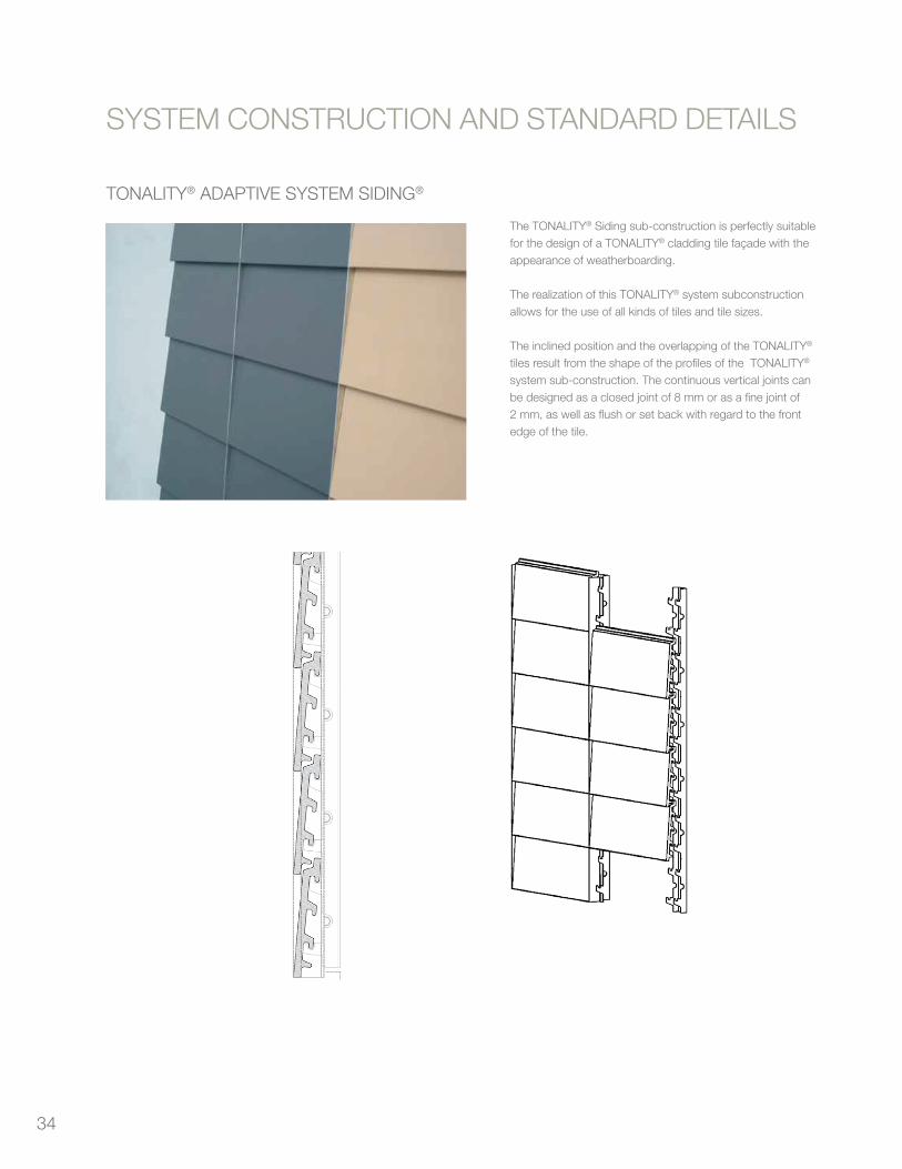
34
TONALITY® ADAPTIVE SYSTEM SIDING®
SYSTEM CONSTRUCTION AND STANDARD DETAILS
The TONALITY® Siding sub-construction is perfectly suitable for the design of a TONALITY® cladding tile façade with the appearance of weatherboarding.
The realization of this TONALITY® system subconstruction allows for the use of all kinds of tiles and tile sizes.
The inclined position and the overlapping of the TONALITY® tiles result from the shape of the profiles of the TONALITY® system sub-construction. The continuous vertical joints can be designed as a closed joint of 8 mm or as a fine joint of 2 mm, as well as flush or set back with regard to the front edge of the tile.
36 Cladding tile tonality®
SYSTEMCONSTRUCTIONANDSTANDARDDETAILSSYSTEM CONSTRUCTION AND STANDARD DETAILS
Adaptive System TONALITY® SIDING®
The TONALITY® Siding sub-construction is per-fectly suitable for the design of a TONALITY®
cladding tile façade with the appearance ofweatherboarding.The realization of this TONALITY® system sub-construction allows for the use of all kinds oftiles and tile sizes.The inclined position and the overlapping of theTONALITY® tiles result from the shape of theprofiles of the TONALITY® system sub-construc-tion.The continuous vertical joints can be designedas a closed joint of 8 mm or as a fine joint of 2mm, as well as flush or set back with regard tothe front edge of the tile.
36Planning & Application 2009 Cladding tiles TONALITY®
TonalityWafu_GB_2009-2.qxp:Tonality_2009 04.08.2009 8:02 Uhr Seite 36
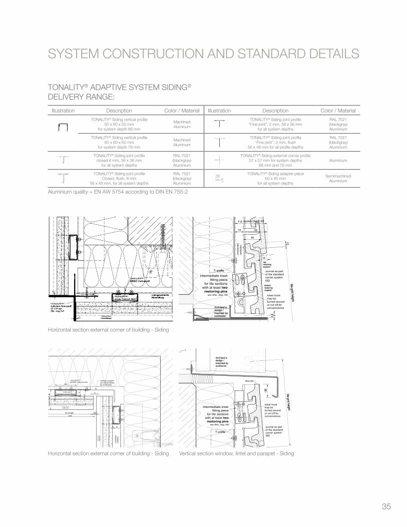
35
TONALITY® ADAPTIVE SYSTEM SIDING®
DELIVERY RANGE:
Aluminium quality = EN AW 5754 according to DIN EN 755-2
Cladding tile tonality® 37
SYSTEMCONSTRUCTIONANDSTANDARDDETAILS
Adaptive System TONALITY® SIDING®
SYSTEM CONSTRUCTION AND STANDARD DETAILS
Horizontal section external corner of building - Siding
tile length
axis
"TONALITY® "-adaptive end lug 56x5
"TONALITY® "-SIDING vertical profile
8
vertical supportalu metal sheet,by contractor
4 4
"TONALITY® "cladding tile
219
60
"TON
ALITY®
"cl
addi
ng ti
le
2 19
unre
stric
ted
vent
ilatio
n
varia
bel
syst
em d
epth
66
44intermediate inset
fitting piecefor tile sections
with at least tworestoring pins
see ANo. dwg 746
19 46
e.g. system depth 66
unre
strict
edve
ntila
tion
12
12
journal as partof the standardcarrier systemSID
lower hookmay beturned aroundor cut off forconvencience
36
Horizontal section internal corner of building - Siding Vertical section window, lintel and parapet - Siding
fitted tile
journal as partof the standardcarrier systemSID
intermediate insetfitting piece
for tile sectionswith at least two
restoring pinssee ANo. dwg 746
lower hookmay beturned aroundor cut off forconvencience
Delivery range: Illustration Description
TONALITY® Siding vertical profile50 x 60 x 50 mm
for system depth 66 mm
TONALITY® Siding vertical profile60 x 60 x 60 mm
for system depth 76 mm
TONALITY® Siding joint profileclosed 8 mm, 56 x 36 mm
for all system depths
TONALITY® Siding joint profileClosed, flush, 8 mm
56 x 48 mm, for all system depths
Color / Material
MachinedAluminium
MachinedAluminium
RAL 7021(blackgray)Aluminium
RAL 7021(blackgray)Aluminium
Illustration Description
TONALITY® Siding joint profile“Fine joint”, 2 mm, 56 x 36 mm
for all system depths
TONALITY® Siding joint profile“Fine joint”, 2 mm, flush
56 x 48 mm for all profile depths
TONALITY® Siding external corner profile57 x 57 mm for system depths
66 mm and 76 mm
TONALITY® Siding adapter piece50 x 45 mm
for all system depths
Color / Material
RAL 7021(blackgray)Aluminium
RAL 7021(blackgray)Aluminium
Aluminium
SemimachinedAluminium
Aluminium quality = EN AW 5754 according to DIN EN 755-2
37Planning & Application 2009 Cladding tiles TONALITY®
TonalityWafu_GB_2009-2.qxp:Tonality_2009 04.08.2009 8:02 Uhr Seite 37
Horizontal section external corner of building - Siding
Cladding tile tonality® 37
SYSTEMCONSTRUCTIONANDSTANDARDDETAILS
Adaptive System TONALITY® SIDING®
SYSTEM CONSTRUCTION AND STANDARD DETAILS
Horizontal section external corner of building - Siding
tile length
axis
"TONALITY® "-adaptive end lug 56x5
"TONALITY® "-SIDING vertical profile
8
vertical supportalu metal sheet,by contractor
4 4
"TONALITY® "cladding tile
219
60
"TON
ALITY®
"cl
addi
ng ti
le
2 19
unre
stric
ted
vent
ilatio
n
varia
bel
syst
em d
epth
66
44
intermediate insetfitting piece
for tile sectionswith at least two
restoring pinssee ANo. dwg 746
19 46
e.g. system depth 66
unre
strict
edve
ntila
tion
12
12
journal as partof the standardcarrier systemSID
lower hookmay beturned aroundor cut off forconvencience
36
Horizontal section internal corner of building - Siding Vertical section window, lintel and parapet - Siding
fitted tile
journal as partof the standardcarrier systemSID
intermediate insetfitting piece
for tile sectionswith at least two
restoring pinssee ANo. dwg 746
lower hookmay beturned aroundor cut off forconvencience
Delivery range: Illustration Description
TONALITY® Siding vertical profile50 x 60 x 50 mm
for system depth 66 mm
TONALITY® Siding vertical profile60 x 60 x 60 mm
for system depth 76 mm
TONALITY® Siding joint profileclosed 8 mm, 56 x 36 mm
for all system depths
TONALITY® Siding joint profileClosed, flush, 8 mm
56 x 48 mm, for all system depths
Color / Material
MachinedAluminium
MachinedAluminium
RAL 7021(blackgray)Aluminium
RAL 7021(blackgray)Aluminium
Illustration Description
TONALITY® Siding joint profile“Fine joint”, 2 mm, 56 x 36 mm
for all system depths
TONALITY® Siding joint profile“Fine joint”, 2 mm, flush
56 x 48 mm for all profile depths
TONALITY® Siding external corner profile57 x 57 mm for system depths
66 mm and 76 mm
TONALITY® Siding adapter piece50 x 45 mm
for all system depths
Color / Material
RAL 7021(blackgray)Aluminium
RAL 7021(blackgray)Aluminium
Aluminium
SemimachinedAluminium
Aluminium quality = EN AW 5754 according to DIN EN 755-2
37Planning & Application 2009 Cladding tiles TONALITY®
TonalityWafu_GB_2009-2.qxp:Tonality_2009 04.08.2009 8:02 Uhr Seite 37
Horizontal section external corner of building - Siding Vertical section window, lintel and parapet - Siding
SYSTEM CONSTRUCTION AND STANDARD DETAILS
Illustration Description Color / Material
TONALITY® Siding vertical profile50 x 60 x 50 mm
for system depth 66 mm
MachinedAluminum
TONALITY® Siding vertical profile60 x 60 x 60 mm
for system depth 76 mm
MachinedAluminum
TONALITY® Siding joint profileclosed 8 mm, 56 x 36 mm
for all system depths
RAL 7021(blackgray)Aluminium
TONALITY® Siding joint profileClosed, flush, 8 mm
56 x 48 mm, for all system depths
RAL 7021(blackgray)Aluminium
Illustration Description Color / Material
TONALITY® Siding joint profile“Fine joint”, 2 mm, 56 x 36 mm
for all system depths
RAL 7021(blackgray)Aluminium
TONALITY® Siding joint profile“Fine joint”, 2 mm, flush
56 x 48 mm for all profile depths
RAL 7021(blackgray)Aluminium
TONALITY® Siding external corner profile57 x 57 mm for system depths
66 mm and 76 mmAluminium
TONALITY® Siding adapter piece50 x 45 mm
for all system depths
SemimachinedAluminium
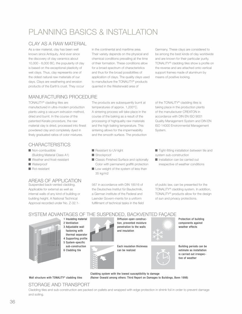
36
CLAY AS A RAW MATERIALAs a raw material, clay has been well known since Antiquity. And ever since the discovery of clay ceramics about 10,000 - 8,000 BC, the popularity of clay is based on the exceptional plasticity of wet clays. Thus, clay represents one of the oldest natural raw materials of our days. Clays are weathering and erosion products of the Earth’s crust. They occur
in the continental and maritime area. Their variety depends on the physical and chemical conditions prevailing at the time of their formation. These conditions allow for a broad spectrum of characteristics and thus for the broad possibilities of application of clays. The quality clays used to manufacture the TONALITY® productsquarried in the Westerwald area of
Germany. These clays are considered to be among the best kinds of clay worldwide and are known for their particular purity.TONALITY® cladding tiles show a profile on the reverse and are attached onto vertical support frames made of aluminum by means of positive locking.
MANUFACTURING PROCEDURETONALITY® cladding tiles are manufactured in ultra-modern production plants using a vacuum extrusion method, dried and burnt. In the course of the patented Keralis procedure, the raw material clay is dried, processed into finest powdered clay and completely dyed in finely graduated ratios of color mixtures.
The products are subsequently burnt at temperatures of approx. 1,200°C.A sintering process will take place in the course of the baking as a result of the processing of highquality raw materials and the high baking temperature. This sintering allows for the impermeabilityand the smooth surface. The production
of the TONALITY® cladding tiles is taking place in the production plants of the manufacturer CREATON in accordance with DIN EN ISO 9001 Quality Management System and DIN EN ISO 14000 Environmental Management System.
CHARACTERISTICS Non-combustible
(Building Material Class A1) Weather and frost-resistant Waterproof Rot-resistant
Resistant to UV-light Shockproof Classic Finished Surface and optionally Color with permanent graffiti protection
Low weight of the system of less than 35 kg/m2
Tight-fitting installation between tile andsystem sub-construction
Installation can be carried out irrespective of weather conditions
AREAS OF APPLICATIONSuspended back-vented cladding. Applicable for external as well as internal walls of any kind of building or building height. A National Technical Approval recorded under No. Z-32.1-
567 in accordance with DIN 18516 of the Deutsches Institut für Bautechnik, a German institute of the Federal and Laender Govern-ments for a uniform fulfillment of technical tasks in the field
of public law, can be presented for the TONALITY® cladding system. In addition, TONALITY® products allow for the design of sun and privacy protections.
SYSTEM ADVANTAGES OF THE SUSPENDED, BACKVENTED FAçADE
38 Cladding tile tonality®
PLANNINGBASESANDPROCESSING
Clay as a raw material
Manufacturing procedure
PLANNING BASES AND PROCESSING
As a raw material, clay has been well knownsince Antiquity. And ever since the discovery ofclay ceramics about 10,000 - 8,000 BC, the popu-larity of clay is based on the exceptional plasticityof wet clays. Thus, clay represents one of the old-est natural raw materials of our days. Clays areweathering and erosion products of the Earth’s
crust. They occur in the continental and maritimearea. Their variety depends on the physical andchemical conditions prevailing at the time of theirformation. These conditions allow for a broadspectrum of characteristics and thus for the broadpossibilities of application of clays. The qualityclays used to manufacture the TONALITY® products
quarried in the Westerwald area of Germany. Theseclays are considered to be among the best kinds ofclay worldwide and are known for their particularpurity.TONALITY® cladding tiles show a profile on thereverse and are attached onto vertical support framesmade of aluminum by means of positive locking.
TONALITY® cladding tiles are manufactured inultra-modern production plants using a vacuumextrusion method, dried and burnt. In the course ofthe patented Keralis procedure, the raw materialclay is dried, processed into finest powdered clayand completely dyed in finely graduated ratios of
color mixtures. The products are subsequentlyburnt at temperatures of approx. 1,200°C.A sintering process will take place in the course ofthe baking as a result of the processing of high-quality raw materials and the high baking temper-ature. This sintering allows for the impermeability
and the smooth surface. The production of theTONALITY® cladding tiles is taking place in the pro-duction plants of the manufacturer CREATON inaccordance with DIN EN ISO 9001 QualityManagement System and DIN EN ISO 14000Environmental Management System.
Characteristics■ Non-combustible
(Building Material Class A1)■ Weather and frost-resistant■ Waterproof■ Rot-resistant
■ Resistant to UV-light■ Shockproof■ Classic Finished Surface and optionally Color
with permanent graffiti protection
■ Low weight of the system of less than 35 kg/m2
■ Tight-fitting installation between tile andsystem sub-construction
■ Installation can be carried out irrespective ofweather conditions
Areas of applicationSuspended back-vented cladding. Applicablefor external as well as internal walls of any kindof building or building height. A National TechnicalApproval recorded under No. Z-32.1-567 in
accordance with DIN 18516 of the DeutschesInstitut für Bautechnik, a German institute ofthe Federal and Laender Govern-ments for auniform fulfillment of technical tasks in the field
of public law, can be presented for the TONALITY®
cladding system. In addition, TONALITY® prod-ucts allow for the design of sun and privacyprotections.
System advantages of the suspended, back-vented façade1 Insulating material2 Ventilation3 Adjustable wall
fastening withthermal separator
4 Supporting profile5 System-specific
sub-construction6 Cladding tile
Diffusion-open construc-tion, prevented moisturepenetration to the wallsand insulation
Each insulation thicknesscan be realized
Protection of buildingcomponents againstweather effects
Building periods can beestimate as installationis carried out irrespec-tive of weather
DisposalCladding tiles can be disposed of as construc-tion and demolition waste under the waste keynumber 17.01.03 (tiles, bricks and ceramicsaccording to the European Waste Catalogue).
The separation of materials allows for theirsupply for high-quality recycling. The aluminumprofiles can be disposed of as reusable materi-al or as construction and demolition waste
under the waste key number 17.04.02(Aluminum according to the European WasteCatalogue).
Storage and transportCladding tiles and sub-construction arepacked on pallets and wrapped with edge pro-
tection in shrink foil in order to prevent dam-age and soiling.
Wall structure with TONALITY® cladding tiles Cladding system with the lowest susceptibility to damage (Rainer Oswald among others: Third Report on Damages to Buildings, Bonn 1998)
38Planning & Application 2009 Cladding tiles TONALITY®
TonalityWafu_GB_2009-2.qxp:Tonality_2009 04.08.2009 8:02 Uhr Seite 38
STORAGE AND TRANSPORTCladding tiles and sub-construction are packed on pallets and wrapped with edge protection in shrink foil in order to prevent damageand soiling.
PLANNING BASICS & INSTALLATION
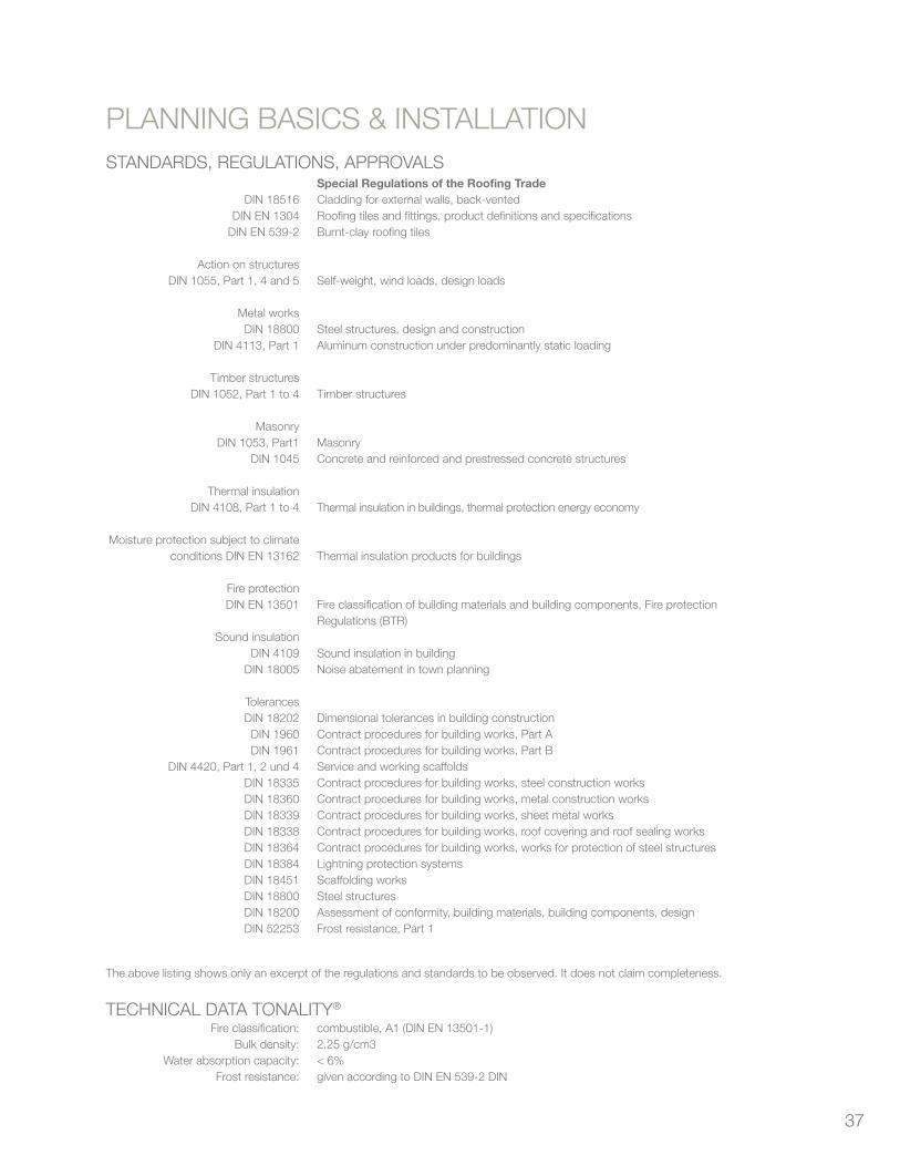
37
DIN 18516DIN EN 1304
DIN EN 539-2
Action on structuresDIN 1055, Part 1, 4 and 5
Metal worksDIN 18800
DIN 4113, Part 1
Timber structuresDIN 1052, Part 1 to 4
MasonryDIN 1053, Part1
DIN 1045
Thermal insulationDIN 4108, Part 1 to 4
Moisture protection subject to climateconditions DIN EN 13162
Fire protectionDIN EN 13501
Sound insulationDIN 4109
DIN 18005
TolerancesDIN 18202DIN 1960DIN 1961
DIN 4420, Part 1, 2 und 4DIN 18335DIN 18360DIN 18339DIN 18338DIN 18364DIN 18384DIN 18451DIN 18800DIN 18200DIN 52253
Special Regulations of the Roofing TradeCladding for external walls, back-ventedRoofing tiles and fittings, product definitions and specificationsBurnt-clay roofing tiles
Self-weight, wind loads, design loads
Steel structures, design and constructionAluminum construction under predominantly static loading
Timber structures
MasonryConcrete and reinforced and prestressed concrete structures
Thermal insulation in buildings, thermal protection energy economy
Thermal insulation products for buildings
Fire classification of building materials and building components, Fire protection Regulations (BTR)
Sound insulation in buildingNoise abatement in town planning
Dimensional tolerances in building constructionContract procedures for building works, Part AContract procedures for building works, Part BService and working scaffoldsContract procedures for building works, steel construction worksContract procedures for building works, metal construction worksContract procedures for building works, sheet metal worksContract procedures for building works, roof covering and roof sealing worksContract procedures for building works, works for protection of steel structuresLightning protection systemsScaffolding worksSteel structuresAssessment of conformity, building materials, building components, designFrost resistance, Part 1
Fire classification:Bulk density:
Water absorption capacity:Frost resistance:
combustible, A1 (DIN EN 13501-1)2.25 g/cm3< 6%given according to DIN EN 539-2 DIN
STANDARDS, REGULATIONS, APPROVALS
The above listing shows only an excerpt of the regulations and standards to be observed. It does not claim completeness.
TECHNICAL DATA TONALITY®
PLANNING BASICS & INSTALLATION

38
ADAPTIVE SYSTEM (ADS)
Installation of vertical profiles:
The TONALITY® vertical profiles must be screwed resp. riveted to the height and the façade grid of the
already installed sub- construction. The distance between brackets and the kind of fastening must be
effected according to the static requirements of the building. Fixing material admitted for use by the
construction supervising authority must be used at any rate. As already described for the primary sub-
construction, gaps for the linear expansion of profiles must be allowed for at the joints in the course of the
profile installation. It must be paid attention to the fact that the required gap at the joint is executed observing
the same height grid of the primary sub-construction (Tprofile) and of the agraffe profile. In case of formation
of several bearing profiles one above the other, the lengths of the bearing profiles as well as the distance
between the fixed points of two bearing profiles following each other must not exceed 2.80 m. The gap at
the joint of the cladding tiles and bearing profiles must be at least 6 mm. Corresponding gaps at the joints
must be allowed for in the event of site trimming. Joints of the bearing profiles may not be overlapped by
cladding tiles.
Installation of joint profile:
In order to fasten the joint profile, it is clamped into the vertical profile. At the same time, it rests on the
beads executed in the webs of the joint profile on the reverse side. As a rule, it is secured against falling off
through insertion of the tiles. At the same time, the tiles are pushed to the vertical profile by the joint profile
in order to avoid the generation of noise of the tiles in case of load from wind pressure. Attention must be
paid to the height locks of the system profiles when inserting the joint profile and to the fact that the joint
profile is inserted in such way that the required clamping effect of the tiles is achieved. In case of soffits,
we recommend to screw the joint profile onto the vertical profile in order to completely rule out a possible
horizontal shifting of the joint profile and of the inserted tiles.
PLANNING BASICS & INSTALLATION
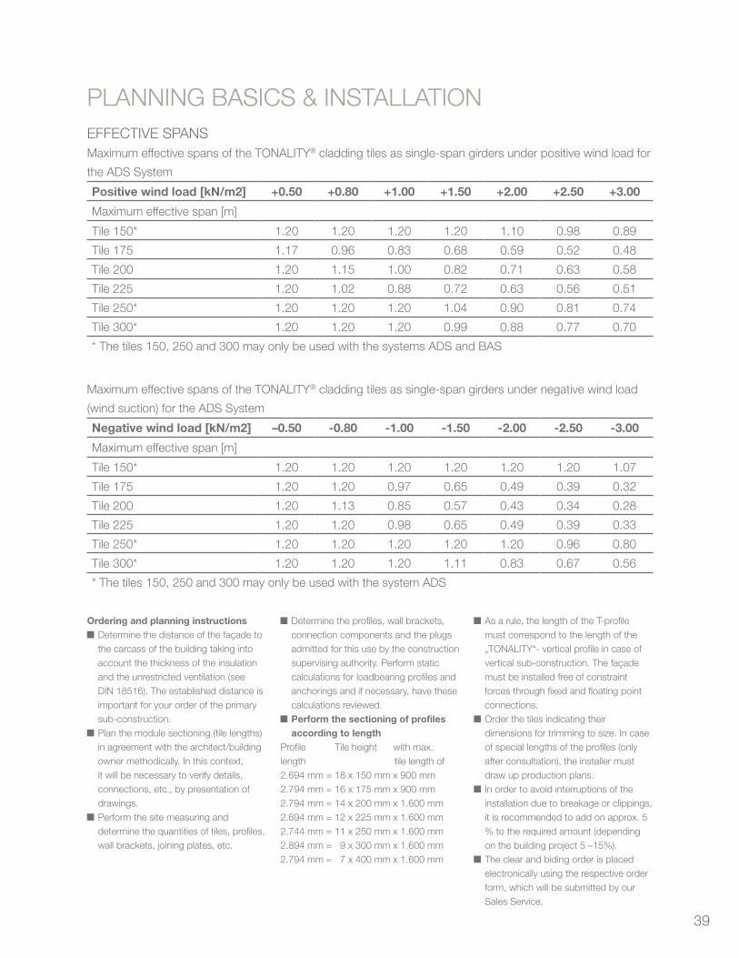
39
EFFECTIVE SPANSMaximum effective spans of the TONALITY® cladding tiles as single-span girders under positive wind load for
the ADS System
Positive wind load [kN/m2] +0.50 +0.80 +1.00 +1.50 +2.00 +2.50 +3.00
Maximum effective span [m]
Tile 150* 1.20 1.20 1.20 1.20 1.10 0.98 0.89
Tile 175 1.17 0.96 0.83 0.68 0.59 0.52 0.48
Tile 200 1.20 1.15 1.00 0.82 0.71 0.63 0.58
Tile 225 1.20 1.02 0.88 0.72 0.63 0.56 0.51
Tile 250* 1.20 1.20 1.20 1.04 0.90 0.81 0.74
Tile 300* 1.20 1.20 1.20 0.99 0.88 0.77 0.70
* The tiles 150, 250 and 300 may only be used with the systems ADS and BAS
Maximum effective spans of the TONALITY® cladding tiles as single-span girders under negative wind load
(wind suction) for the ADS System
Negative wind load [kN/m2] –0.50 -0.80 -1.00 -1.50 -2.00 -2.50 -3.00
Maximum effective span [m]
Tile 150* 1.20 1.20 1.20 1.20 1.20 1.20 1.07
Tile 175 1.20 1.20 0.97 0.65 0.49 0.39 0.32
Tile 200 1.20 1.13 0.85 0.57 0.43 0.34 0.28
Tile 225 1.20 1.20 0.98 0.65 0.49 0.39 0.33
Tile 250* 1.20 1.20 1.20 1.20 1.20 0.96 0.80
Tile 300* 1.20 1.20 1.20 1.11 0.83 0.67 0.56
* The tiles 150, 250 and 300 may only be used with the system ADS
PLANNING BASICS & INSTALLATION
Ordering and planning instructions Determine the distance of the façade to the carcass of the building taking into account the thickness of the insulation and the unrestricted ventilation (see DIN 18516). The established distance is important for your order of the primary sub-construction.
Plan the module sectioning (tile lengths) in agreement with the architect/building owner methodically. In this context, it will be necessary to verify details, connections, etc., by presentation of drawings.
Perform the site measuring and determine the quantities of tiles, profiles, wall brackets, joining plates, etc.
Determine the profiles, wall brackets, connection components and the plugs admitted for this use by the construction supervising authority. Perform static calculations for loadbearing profiles and anchorings and if necessary, have these calculations reviewed.
Perform the sectioning of profiles according to length
Profile Tile height with max.length tile length of2.694 mm = 18 x 150 mm x 900 mm2.794 mm = 16 x 175 mm x 900 mm2.794 mm = 14 x 200 mm x 1.600 mm2.694 mm = 12 x 225 mm x 1.600 mm2.744 mm = 11 x 250 mm x 1.600 mm2.894 mm = 9 x 300 mm x 1.600 mm2.794 mm = 7 x 400 mm x 1.600 mm■
As a rule, the length of the T-profile must correspond to the length of the „TONALITY“- vertical profile in case of vertical sub-construction. The façade must be installed free of constraint forces through fixed and floating point connections.
Order the tiles indicating their dimensions for trimming to size. In case of special lengths of the profiles (only after consultation), the installer must draw up production plans.
In order to avoid interruptions of the installation due to breakage or clippings, it is recommended to add on approx. 5 % to the required amount (depending on the building project 5 –15%).
The clear and biding order is placed electronically using the respective order form, which will be submitted by our Sales Service.
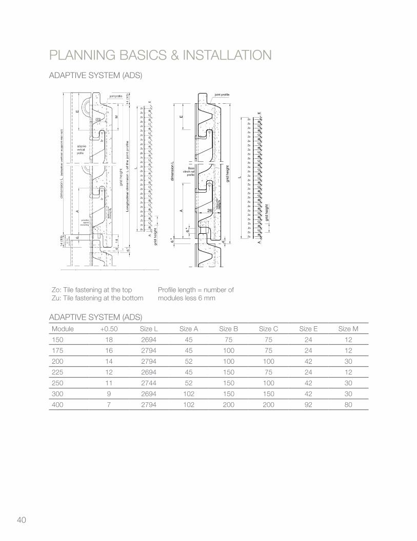
40
ADAPTIVE SYSTEM (ADS)
Cladding tile tonality® 45
PLANNINGBASESANDPROCESSING
Adaptive System (ADS) Base Clinch Rail System (BAS)
PLANNING BASES AND PROCESSING
Base Clinch Rail System (BAS)
Zu
Zo
Zo
Zu
Zo
Zu
Zo
Zu
Zo
Zu
Zo
Zu
Zo
Zu
Zo
Zu
Zo
Zu
Zo
Zu
Zo
Zu
Zo
Zu
Zo
Zu
Zo
Zu
*
joint profile
L
6.
E
Baseclinch rail
profile
grid
hei
ght
grid
hei
ght
dim
ensi
on L
A
4
6.*
* Thermal linear expansion requir 6 mm between both 2 adjacent (see NTA National Technical Ap
26
Zu
Zo
Zo
Zu
Zo
Zu
Zo
Zu
Zo
Zu
Zo
Zu
Zo
Zu
Zo
Zu
Zo
Zu
Zo
Zu
Zo
Zu
Zo
Zu
Zo
Zu
Zo
Zu
* Thermal linear expansion least 6 mm between both (see NTA National Technic
L
Prgr
ZoZu
grid h
eig
ht
Classicverticalprofile
*
joint profile
grid h
eig
ht
dim
en
sion
L
A
6.
E
Zo
Zu
M
26
42
,5
Neoprene
Module
150
175
200
225
250
300
400
No. ofmodules
18
16
14
12
11
9
7
Size L
2694
2794
2794
2694
2744
2694
2794
Size A
45
45
52
45
52
102
102
Size B
75
100
100
150
150
150
200
Size C
75
75
100
75
100
150
200
Size E
24
24
42
24
42
42
92
Size M
12
12
30
12
30
30
80
Adaptive System (ADS)
Module
150
175
200
225
250
300
400
No. ofmodules
18
16
14
12
11
9
7
Size L
2694
2794
2794
2694
2744
2694
2794
Size A
56.5
56.5
63.5
56.5
63.5
113.5
113.5
Size B
75
100
100
150
150
150
200
Size C
75
75
100
75
100
150
200
Size E
12.5
12.5
30.5
12.5
30.5
30.5
80.5
Size M
12
12
30
12
30
30
80
Classic Profile System (CLS)
Module
150
175
200
225
250
300
400
No. ofmodules
18
16
14
12
11
9
7
Size L
2694
2794
2794
2694
2744
2694
2794
Size A
57
57
64
57
64
114
114
Size B
75
100
100
150
150
150
200
Size C
75
75
100
75
100
150
200
Size E
75
100
100
150
150
150
80
45Planning & Application 2009 Cladding tiles TONALITY®
Zo: Tile fastening at the topZu: Tile fastening at the bottom
Profile length = number of modules less 6 mm * For thermal expansion reasons, the joint dis-tance of the tiles and profiles must be at least 6mm (see Technical Approval).
TonalityWafu_GB_2009-2.qxp:Tonality_2009 04.08.2009 8:02 Uhr Seite 45
Zo: Tile fastening at the topZu: Tile fastening at the bottom
Profile length = number of modules less 6 mm
ADAPTIVE SYSTEM (ADS)Module +0.50 Size L Size A Size B Size C Size E Size M
150 18 2694 45 75 75 24 12
175 16 2794 45 100 75 24 12
200 14 2794 52 100 100 42 30
225 12 2694 45 150 75 24 12
250 11 2744 52 150 100 42 30
300 9 2694 102 150 150 42 30
400 7 2794 102 200 200 92 80
PLANNING BASICS & INSTALLATION
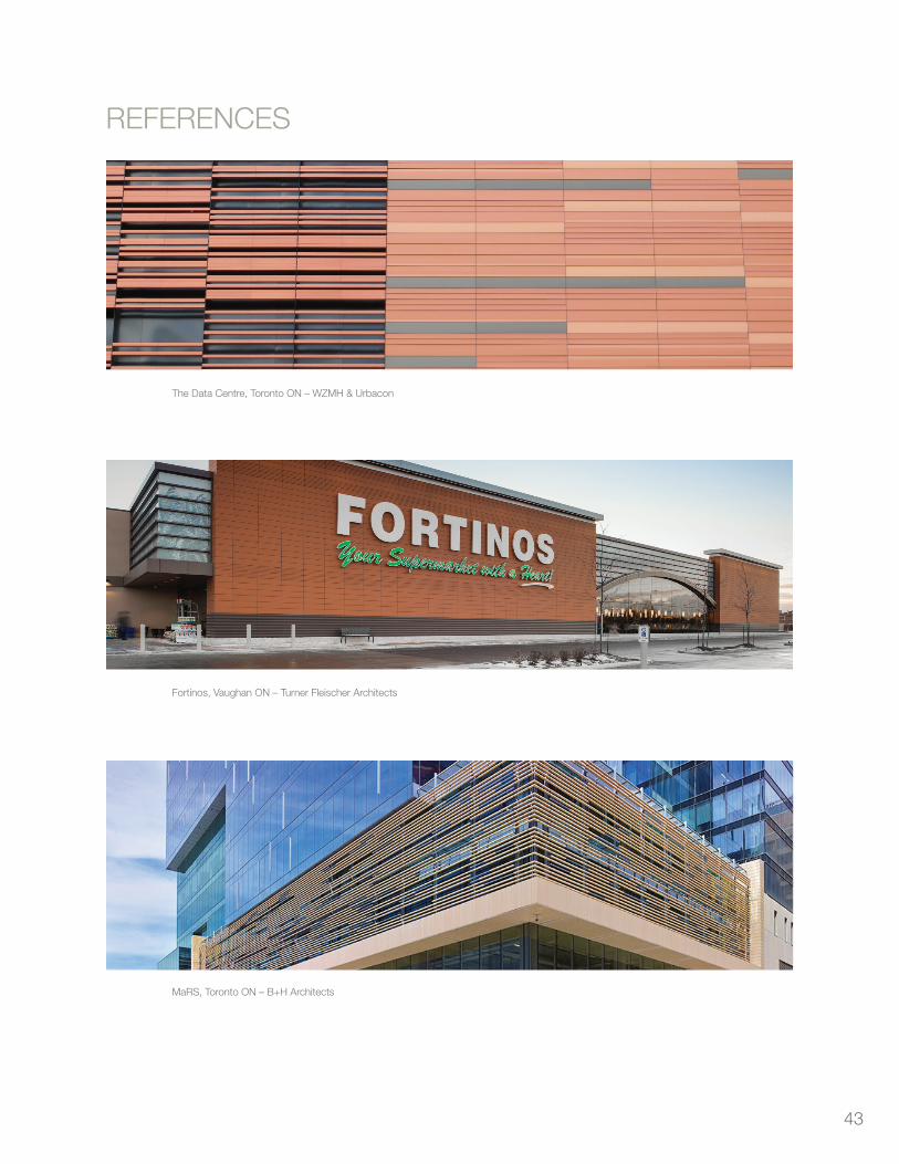
43
REFERENCES
The Data Centre, Toronto ON – WZMH & Urbacon
Fortinos, Vaughan ON – Turner Fleischer Architects
MaRS, Toronto ON – B+H Architects

44
Engineered Assemblies Inc.
1.866.591.7021info@engineeredassemblies.comEngineeredAssemblies.com
brilliant buildings
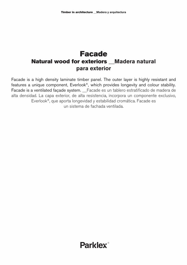
Timber in architecture __Madera y arquitectura
Facade Natural wood for exteriors __Madera natural
para exterior
Facade is a high density laminate timber panel. The outer layer is highly resistant and features a unique component, Everlook®, which provides longevity and colour stability. Facade is a ventilated façade system. __Facade es un tablero estratificado de madera de alta densidad. La capa exterior, de alta resistencia, incorpora un componente exclusivo,
Everlook®, que aporta longevidad y estabilidad cromática. Facade es un sistema de fachada ventilada.
Edition and productionEdición y producciónComposites Gurea S.A.
CoordinationCoordinaciónMirari Olaizola,Jaume Ramírez
TextsTextosAlberto López-Amor
PhotographyFotografíaLuc BoeglyXavier García i MarlíJesús Martín RuizNathaniel McMahon
Art direction and designDirección artística y diseñoRamírez i Carrillo
PrintImpresiónGráficas Ulzama
ParklexCOMPOSITES GUREA, S.A.Zalain auzoa, 13 - 31780 Bera - Navarra - SpainTel. +34 948 625 045 - Fax. +34 948 625 [email protected] - www.parklex.com
Aware of the importance of protecting the environment through responsi-ble and sustainable production, Parklex has obtained the PEFC standard. Parklex’s contribution to sustainable maintenance and improvement of forests and the environment. __Conscientes de la importancia de cuidar el medioambiente para una producción responsable y sostenible, Parklex cuenta con el certificado PEFC. Parklex está colaborando con el manteni-miento sostenible y mejora de los bosques y del medio ambiente.
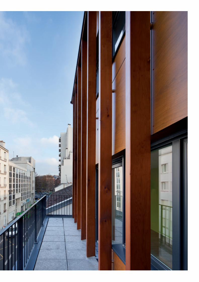
Thorough knowledge of our work from its foundation, the wood, along with an active commitment to the interests and aspirations of design and construction professionals. These are the two core values that support over 40 years’ experi-
ence and now decidedly boost Parklex’s activity.
From origin to destination, from natural wood to architectur-al application, we develop sustainable, innovative production aimed at changing requirements. The result of the process is a wide range of products and finishes for façades and indoor panelling. Its outstanding features are quality materials, easy
installation, resistance to moisture and to intensive use, optimal maintenance and an aesthetic appeal appreciated by
architects from around the world.
Nowadays, Parklex products constitute renowned and ad-mired solutions for all types of buildings. On their exteriors, surfaces, walls, floors and ceilings. In the Guggenheim Mu-
seum Bilbao, Liverpool Airport, the Congress Centre and Auditorium of Navarra and the Air France Lounge at Tokyo
Airport. In wine cellars, hotels, swimming pools and cultural centres. In official institutions, business parks and private
homes. In any building where wood is architecture.
Juan AzcueDirector
Un conocimiento profundo de nuestro trabajo desde su base, la madera, y un compromiso activo con los intereses y las aspiraciones de los profesionales del diseño y la construcción. Son los dos valo-res esenciales que apoyan una experiencia de más de 40 años y que
hoy impulsan decisivamente la actividad de Parklex.
Entre el origen y el destino, entre la madera natural y la aplicación arquitectónica, se desarrolla una producción sostenible, innovadora,
orientada a requisitos cambiantes. El resultado del proceso es un conjunto muy amplio de productos y acabados para revestir facha-
das e interiores. Sus rasgos destacados son la calidad material, una fácil instalación, resistencia a la humedad y al uso intensivo, un man-tenimiento óptimo y un sentido estético apreciado por arquitectos de
todo el mundo.
Hoy los productos Parklex conforman soluciones reconocibles y ad-miradas en todo tipo de edificios. En su exterior, sobre sus superfi-cies, en sus paredes, suelos y techos. En el Museo Guggenheim de Bilbao y en el aeropuerto de Liverpool, en el Palacio de Congresos
de Navarra y en la Sala Vip de Air France en el aeropuerto de Tokyo. En bodegas y hoteles, en piscinas y centros culturales. En sedes de instituciones, en complejos de oficinas y en viviendas particulares.
En cualquier edificación donde la madera sea arquitectura.
Juan AzcueDirector

6
7
Enfolding architecture in a stable and sturdy covering that pro-jects a sound and natural appearance in coexistence with its surroundings. These are the aims of Facade, which technically is a high density laminate timber panel. Manufactured from kraft paper treated with thermoset resins, pressed under high pres-sure and temperature and finished with natural timber veneers highly resistant to UV radiation and atmospheric agents. Facade includes Everlook®, a special overlay that dramatically increases the normal life of the panel, improving UV resistance and colour stability. It also allows for the development of new panels with an extensive range of finishes. __Envolver la arquitectura con un recubrimiento estable y duradero que proyecte una imagen de solidez y naturalidad en la convivencia con su entorno. Estos son los objetivos de la solución Facade, que técnicamente consiste en un tablero es-tratificado de madera de alta densidad. Está constituido interiormente por fibras de papel tratadas con resinas termoendurecidas, compri-midas a altas presiones y temperaturas, y un revestimiento exterior de alta resistencia a la radiación UV y a los agentes atmosféricos. Incorpora Everlook®, un componente que aporta una mayor longevi-dad a la madera frente a cualquier condición climática, mejora la esta-bilidad de los colores y permite disponer de nuevos acabados.
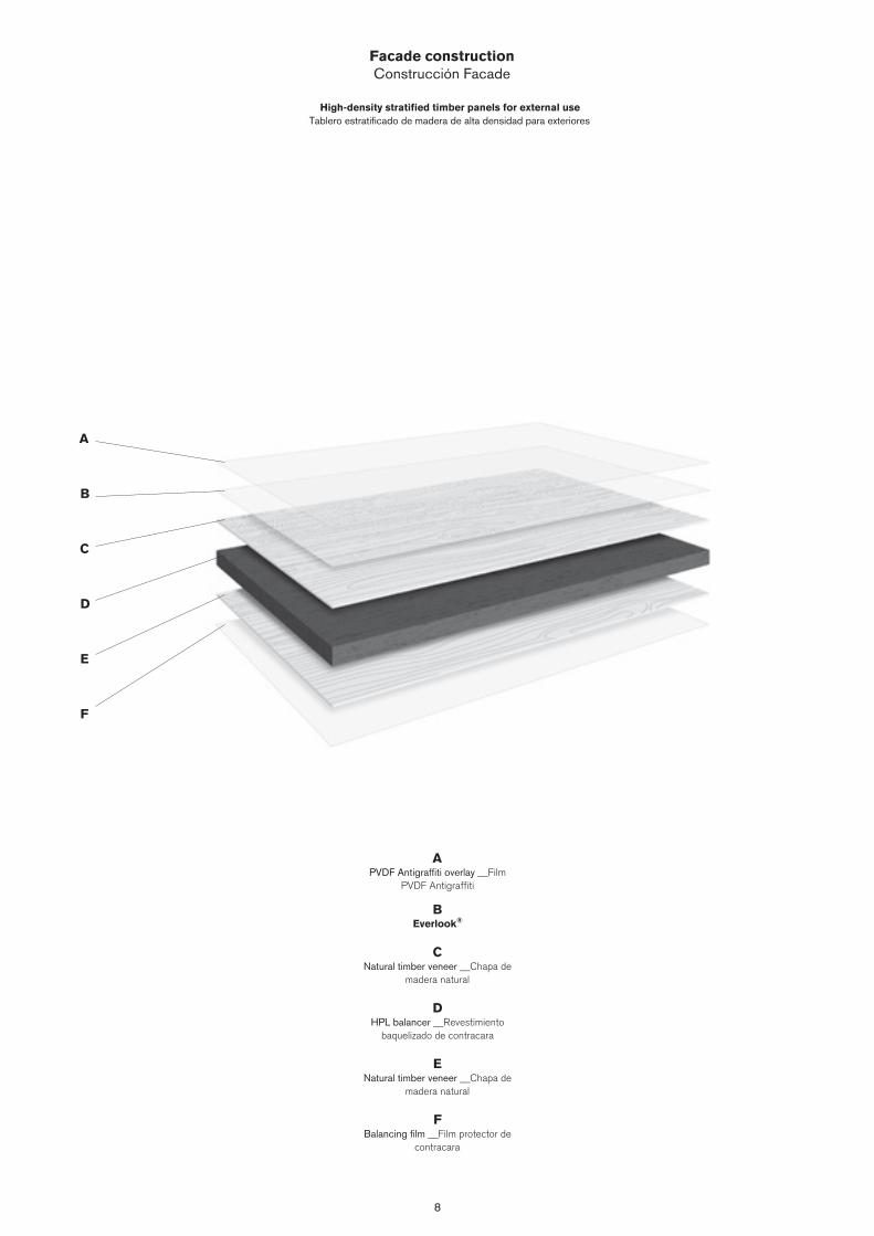
8
Facade constructionConstrucción Facade
High-density stratified timber panels for external useTablero estratificado de madera de alta densidad para exteriores
APVDF Antigraffiti overlay __Film
PVDF Antigraffiti
BEverlook®
CNatural timber veneer __Chapa de
madera natural
DHPL balancer __Revestimiento
baquelizado de contracara
ENatural timber veneer __Chapa de
madera natural
FBalancing film __Film protector de
contracara
A
B
C
D
E
F
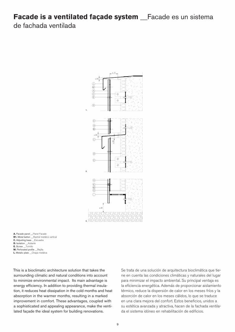
9
This is a bioclimatic architecture solution that takes the surrounding climatic and natural conditions into account to minimize environmental impact. Its main advantage is energy efficiency. In addition to providing thermal insula-tion, it reduces heat dissipation in the cold months and heat absorption in the warmer months, resulting in a marked improvement in comfort. These advantages, coupled with a sophisticated and appealing appearance, make the venti-lated façade the ideal system for building renovations.
Se trata de una solución de arquitectura bioclimática que tie-ne en cuenta las condiciones climáticas y naturales del lugar para minimizar el impacto ambiental. Su principal ventaja es la eficiencia energética. Además de proporcionar aislamiento térmico, reduce la dispersión de calor en los meses fríos y la absorción de calor en los meses cálidos, lo que se traduce en una clara mejora del confort. Estos beneficios, unidos a su estética avanzada y atractiva, hacen de la fachada ventila-da el sistema idóneo en rehabilitación de edificios.
3.
1.
2.
≥ 20
A
B1
D
E
L
C
≥ 20
≥ �0
A
B1
D
E
L
C
≥ 20
�
E
D
B1
A
≥ 20
A. Facade panel __Panel FacadeB1. Metal batten __Rastrel metálico verticalC. Adjusting base __EscuadraD. Isolation __AislanteE. Screw __TornilloM. Perforated profile __RejillaL. Metalic plate __Chapa metálica
Facade is a ventilated façade system __Facade es un sistema de fachada ventilada
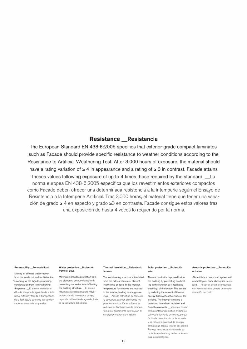
10
Resistance __ResistenciaThe European Standard EN 438-6:2005 specifies that exterior-grade compact laminates
such as Facade should provide specific resistance to weather conditions according to the
Resistance to Artificial Weathering Test. After 3,000 hours of exposure, the material should
have a rating variation of ≥ 4 in appearance and a rating of ≥ 3 in contrast. Facade attains
theses values following exposure of up to 4 times those required by the standard. __La norma europea EN 438-6:2005 especifica que los revestimientos exteriores compactos
como Facade deben ofrecer una determinada resistencia a la intemperie según el Ensayo de Resistencia a la Intemperie Artificial. Tras 3.000 horas, el material tiene que tener una varia-ción de grado ≥ 4 en aspecto y grado ≥3 en contraste. Facade consigue estos valores tras
una exposición de hasta 4 veces lo requerido por la norma.
Permeability __Permeabilidad
Moving air diffuses water vapour
from the inside out and facilitates the
‘breathing’ of the façade, preventing
condensation from forming behind
the panels. __El aire en movimiento
difunde el vapor de agua desde el inte-
rior al exterior y facilita la transpiración
de la fachada, lo que evita las conden-
saciones detrás de los paneles.
Water protection __Protección frente al agua
Moving air provides protection from
the elements, because it assists in
preventing rain water from infiltrating
the building structure. __El aire en
movimiento proporciona una mayor
protección a la intemperie, porque
impide la infiltración de agua de lluvia
en la estructura del edificio.
Thermal insulation __Aislamiento térmico
The load-bearing structure is insulated
from the exterior structure, eliminat-
ing thermal bridges. In this manner,
temperature fluctuations are reduced
in the interior, leading to energy sav-
ings. __Aísla la estructura portante de
la estructura exterior, eliminando los
puentes térmicos. De esta forma se
reducen las fluctuaciones de tempera-
tura en el cerramiento interior, con el
consiguiente ahorro energético.
Solar protection __Protección solar
Thermal comfort is improved inside
the building by preventing overheat-
ing in the summer, as it facilitates
‘breathing’ of the façade. This assists
by reducing the amount of thermal
energy that reaches the inside of the
building. The internal structure is
protected from direct radiation and
from the elements. __Mejora el confort
térmico interior del edifico, evitando el
sobrecalentamiento en verano, porque
facilita la transpiración de la fachada
y se reduce la cantidad de energía
térmica que llega al interior del edificio.
Protege la estructura interna de las
radiaciones directas y de las inclemen-
cias meteorológicas.
Acoustic protection __Protección acústica
Since this is a compound system with
several layers, noise absorption is cre-
ated. __Al ser un sistema compuesto
con varios estratos, genera una mayor
absorción del ruido.
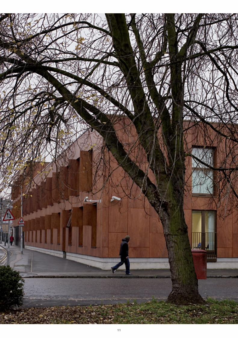
11
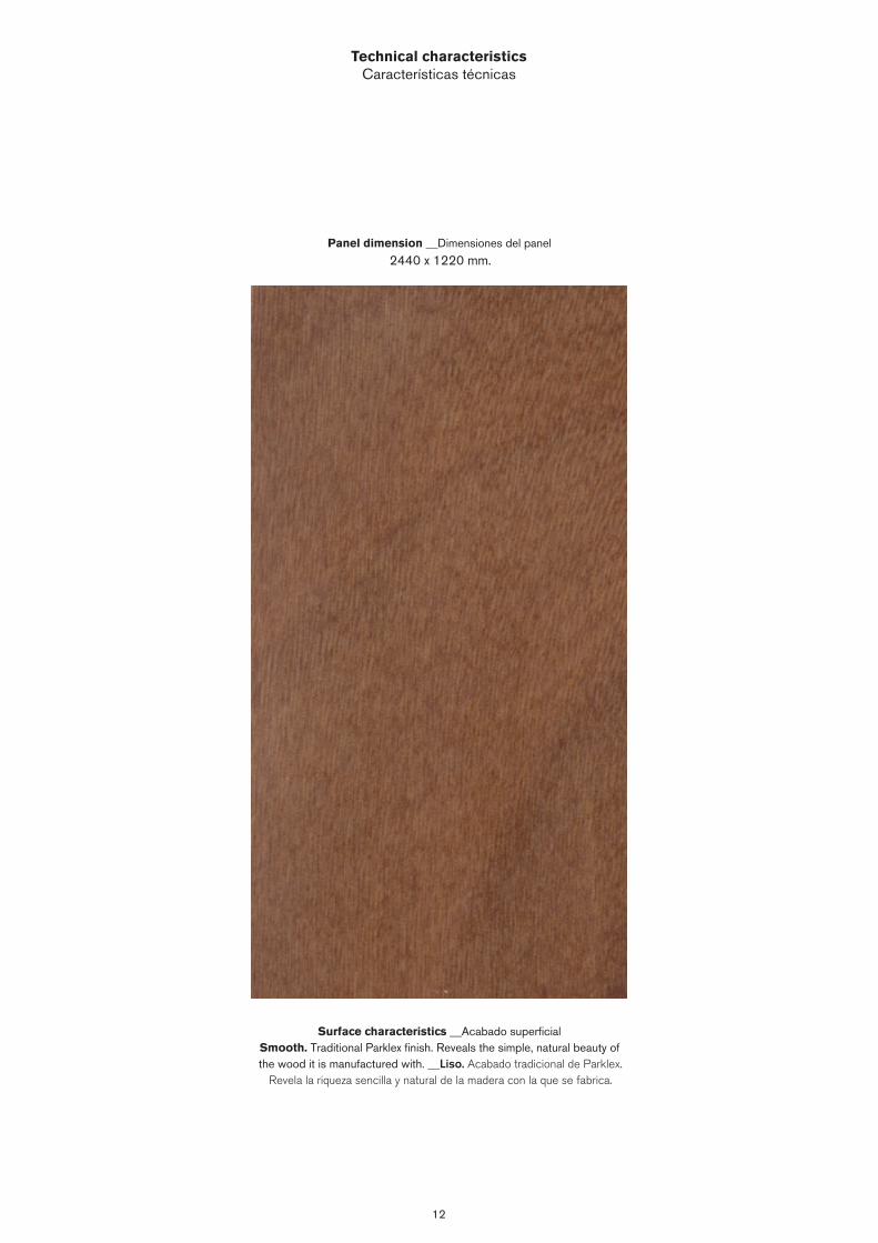
12
Technical characteristicsCaracterísticas técnicas
Panel dimension __Dimensiones del panel
2440 x 1220 mm.
Surface characteristics __Acabado superficialSmooth. Traditional Parklex finish. Reveals the simple, natural beauty of the wood it is manufactured with. __Liso. Acabado tradicional de Parklex.
Revela la riqueza sencilla y natural de la madera con la que se fabrica.
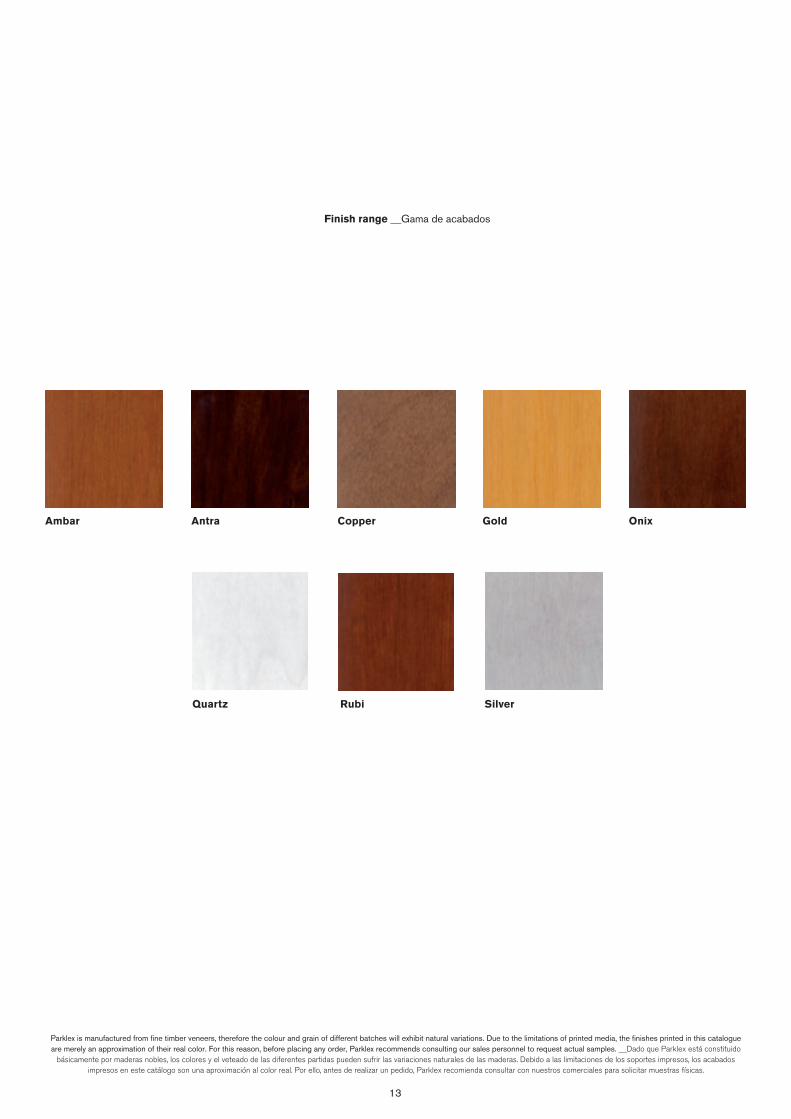
13
Ambar Copper Antra Gold Onix
Quartz Rubi Silver
Finish range __Gama de acabados
Parklex is manufactured from fine timber veneers, therefore the colour and grain of different batches will exhibit natural variations. Due to the limitations of printed media, the finishes printed in this catalogue are merely an approximation of their real color. For this reason, before placing any order, Parklex recommends consulting our sales personnel to request actual samples. __Dado que Parklex está constituido
básicamente por maderas nobles, los colores y el veteado de las diferentes partidas pueden sufrir las variaciones naturales de las maderas. Debido a las limitaciones de los soportes impresos, los acabados impresos en este catálogo son una aproximación al color real. Por ello, antes de realizar un pedido, Parklex recomienda consultar con nuestros comerciales para solicitar muestras físicas.
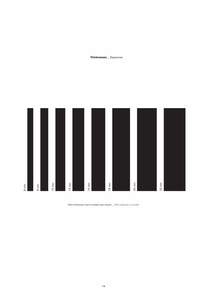
14
6 m
m.
8 m
m.
10 m
m.
12 m
m.
14 m
m.
18 m
m.
20 m
m.
22 m
m.
Thicknesses __Espesores
Other thicknesses may be available upon request. __Otros espesores a consultar.
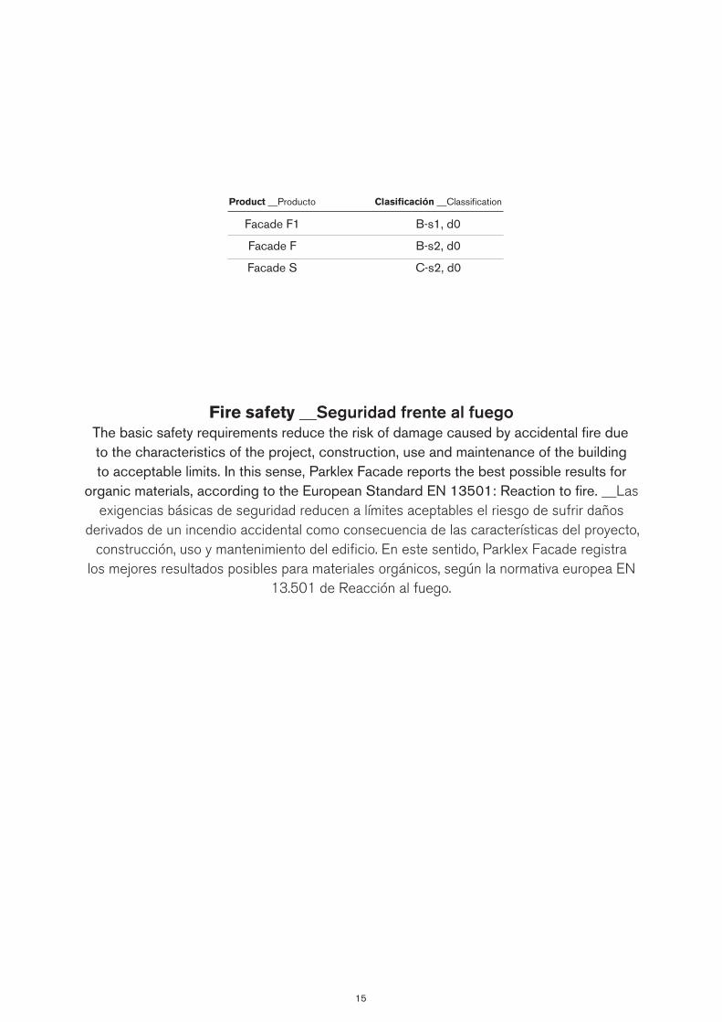
15
Fire safety __Seguridad frente al fuegoThe basic safety requirements reduce the risk of damage caused by accidental fire due to the characteristics of the project, construction, use and maintenance of the building to acceptable limits. In this sense, Parklex Facade reports the best possible results for
organic materials, according to the European Standard EN 13501: Reaction to fire. __Las exigencias básicas de seguridad reducen a límites aceptables el riesgo de sufrir daños
derivados de un incendio accidental como consecuencia de las características del proyecto, construcción, uso y mantenimiento del edificio. En este sentido, Parklex Facade registra
los mejores resultados posibles para materiales orgánicos, según la normativa europea EN 13.501 de Reacción al fuego.
Product __Producto
Facade F1
Facade F
Facade S
Clasificación __Classification
B-s1, d0
B-s2, d0
C-s2, d0

Facade Projects __Proyectos
Housing __Viviendas / ITAR Architectures / Paris, France __Francia / John Lennon Airport / Leach Rhodes Walker / Liver-pool, United Kingdom __Reino Unido / St. Pauls Square / RHWL Architects / Liverpool, United Kingdom __Reino Unido / Student halls of residence __Residencia para estudiantes / Michel,
Wolf & Partner Architects / Würzburg, Germany __Alemania / MUA Alicante University Museum __MUA Museo de la Uni-versidad de Alicante / Alfredo Paya / Alicante, Spain __España / Tianjin Zero power-wasting building / Lai Jun / Tianjin, China / Stoperingaten 25 / Alliance Arkitekt / Norway __Noruega / Fast Line Tel Aviv building __Edificio de Fast Line Tel Aviv / Amir Mann - Ami Shinar Architects & Planners Ltd. / Tel Aviv
__Israel / House in Cyprus __Casa en Chipre / Simpraxis Ar-chitects / Cyprus __Chipre / San Francisco Plaza Apartments / Leddy Maytum Stacy Arquitects & Paulett Taggart Arquitects /
San Francisco, U.S. __E.E.U.U.

18
Housing __Viviendas / ITAR Architectures / Paris, France __Francia
Surface characteristics __Acabado superficialProduct __Producto
Smooth __Liso Traditional Parklex finish. Reveals the simple, natural beauty of the wood it is manufactured with. __Acabado tradicional de Parklex. Revela la riqueza sencilla y natural de la madera con la que se fabrica.
Parklex Finition __Acabado
CopperFacade
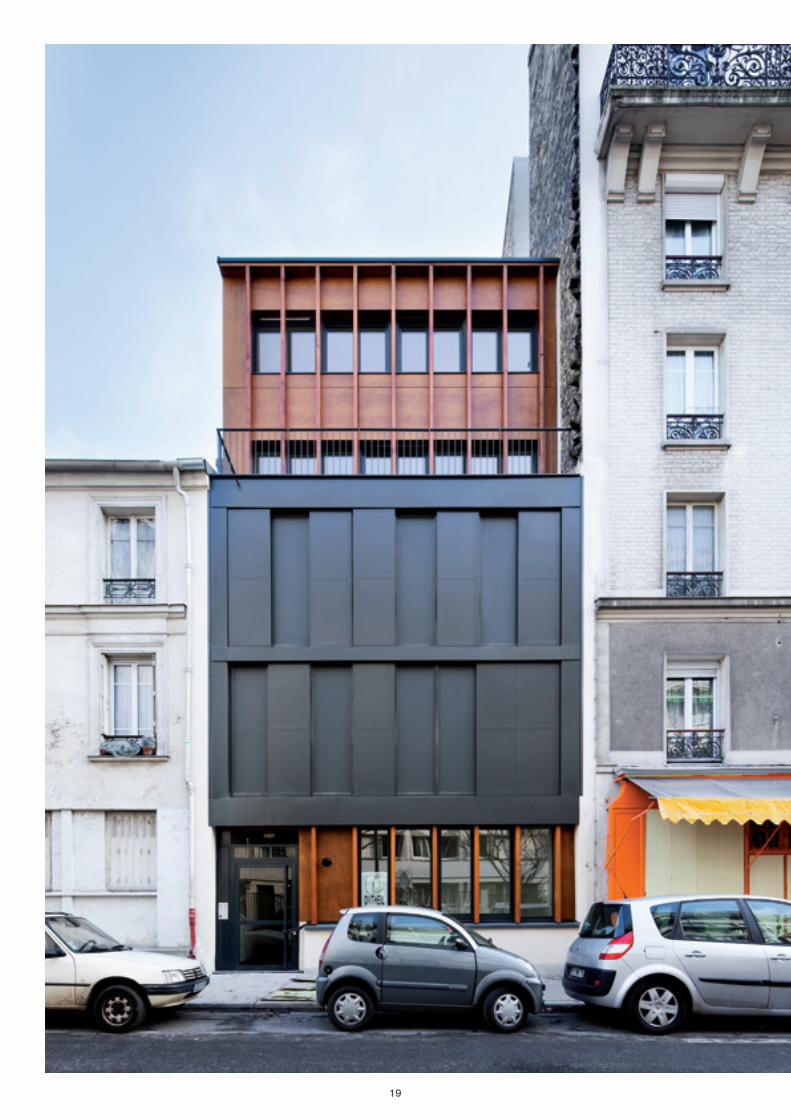
19
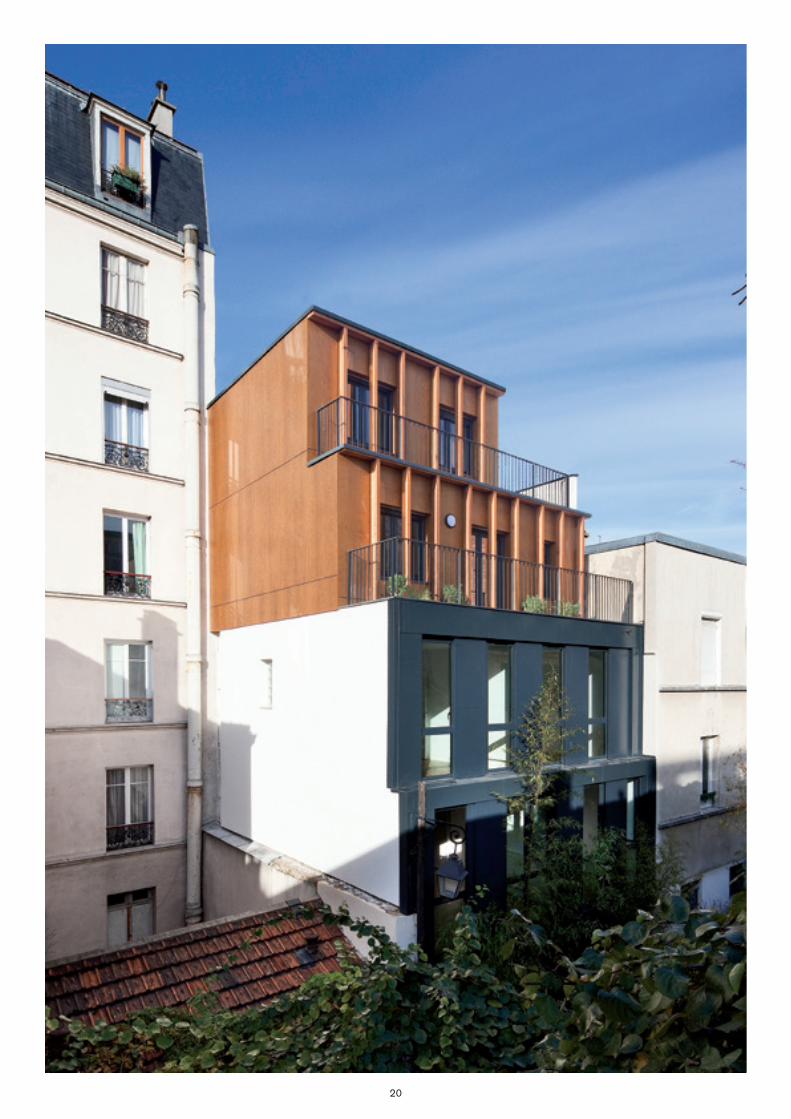
20

21
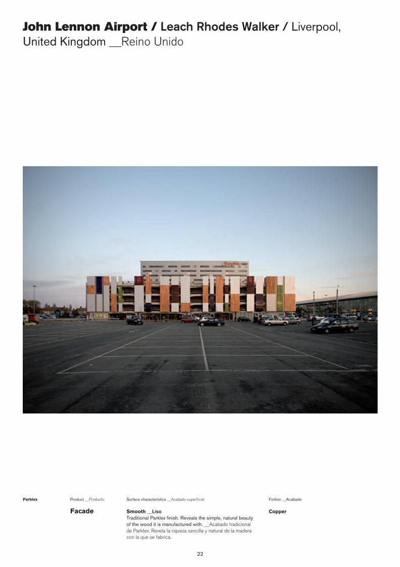
22
John Lennon Airport / Leach Rhodes Walker / Liverpool, United Kingdom __Reino Unido
Surface characteristics __Acabado superficialProduct __Producto
Smooth __Liso Traditional Parklex finish. Reveals the simple, natural beauty of the wood it is manufactured with. __Acabado tradicional de Parklex. Revela la riqueza sencilla y natural de la madera con la que se fabrica.
Parklex Finition __Acabado
CopperFacade
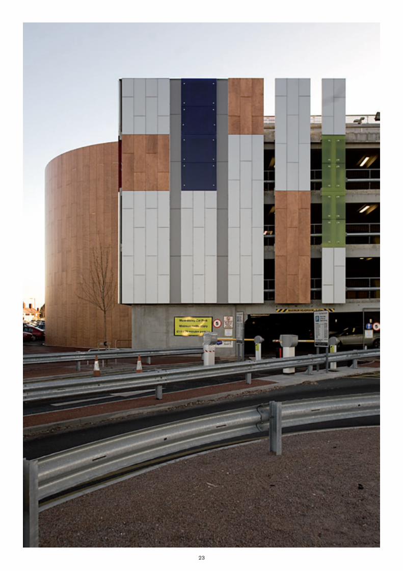
23
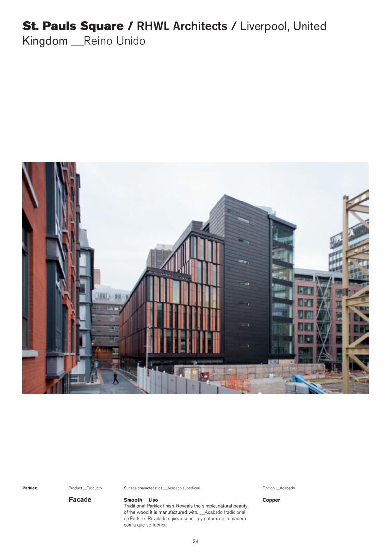
24
St. Pauls Square / RHWL Architects / Liverpool, United Kingdom __Reino Unido
Surface characteristics __Acabado superficialProduct __Producto
Smooth __Liso Traditional Parklex finish. Reveals the simple, natural beauty of the wood it is manufactured with. __Acabado tradicional de Parklex. Revela la riqueza sencilla y natural de la madera con la que se fabrica.
Parklex Finition __Acabado
CopperFacade
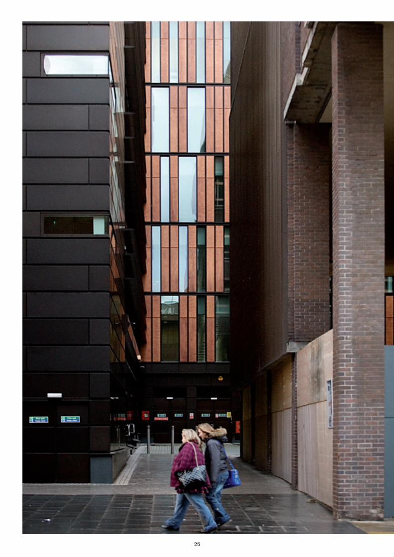
25
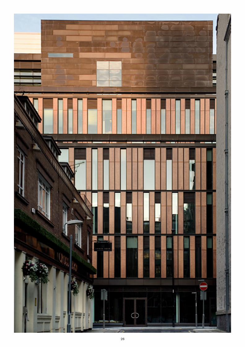
26
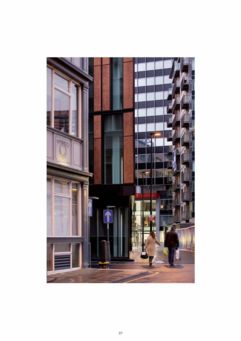
27
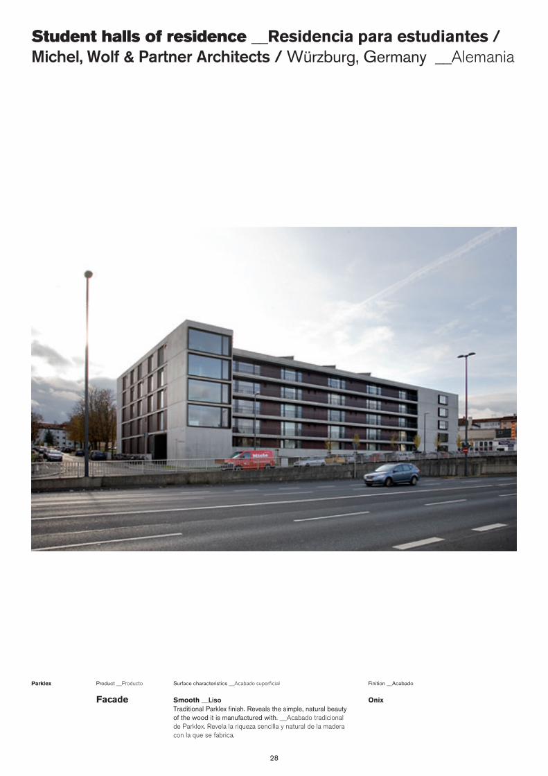
28
Student halls of residence __Residencia para estudiantes / Michel, Wolf & Partner Architects / Würzburg, Germany __Alemania
Surface characteristics __Acabado superficialProduct __Producto
Smooth __Liso Traditional Parklex finish. Reveals the simple, natural beauty of the wood it is manufactured with. __Acabado tradicional de Parklex. Revela la riqueza sencilla y natural de la madera con la que se fabrica.
Parklex Finition __Acabado
OnixFacade

29

30
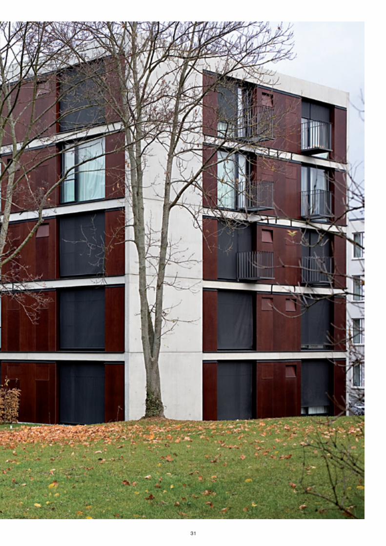
31
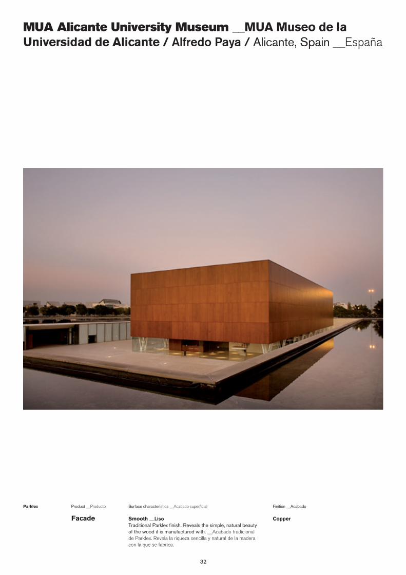
32
MUA Alicante University Museum __MUA Museo de la Universidad de Alicante / Alfredo Paya / Alicante, Spain __España
Surface characteristics __Acabado superficialProduct __Producto
Smooth __Liso Traditional Parklex finish. Reveals the simple, natural beauty of the wood it is manufactured with. __Acabado tradicional de Parklex. Revela la riqueza sencilla y natural de la madera con la que se fabrica.
Parklex Finition __Acabado
CopperFacade
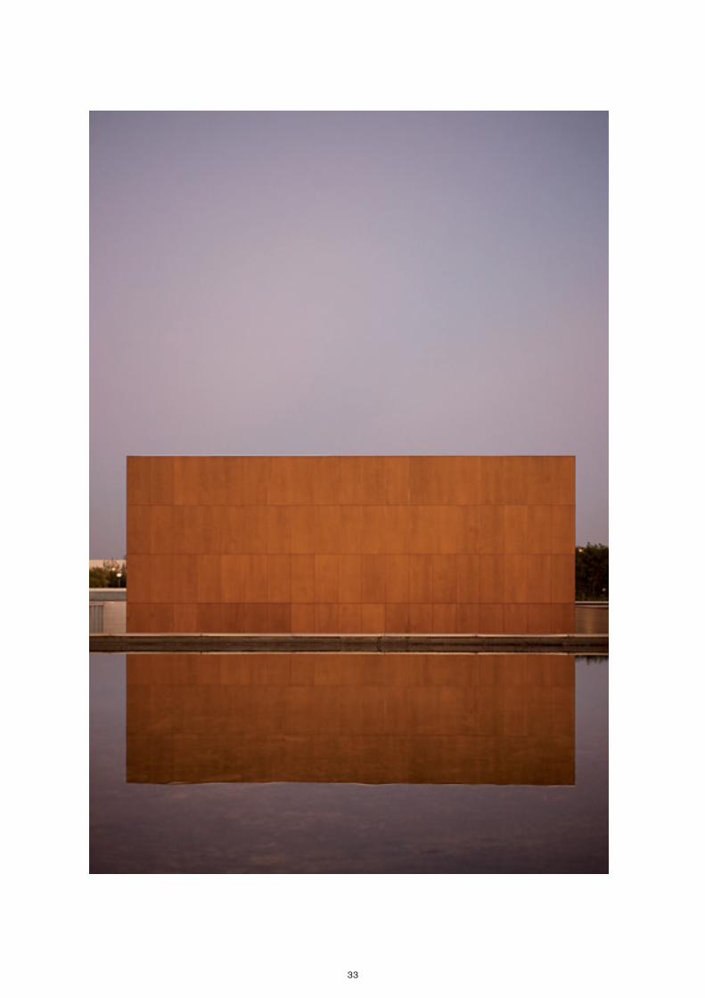
33
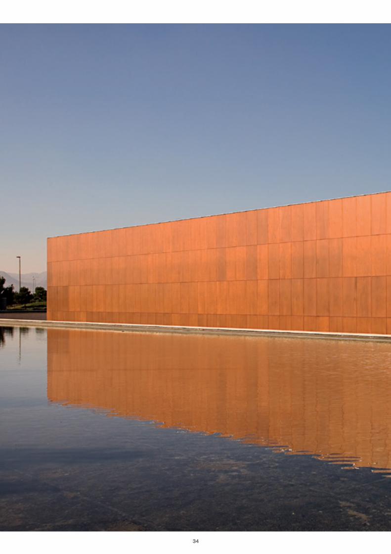
34
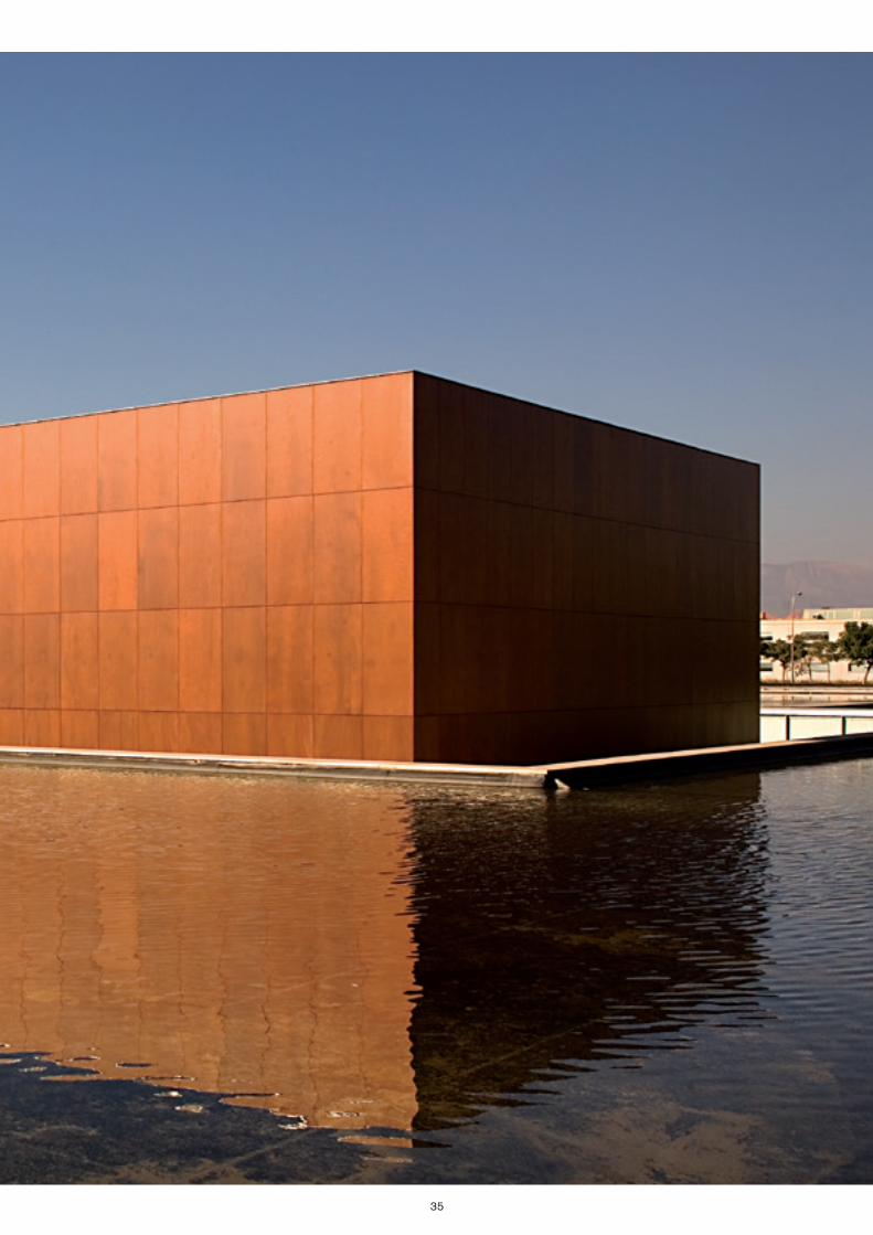
35
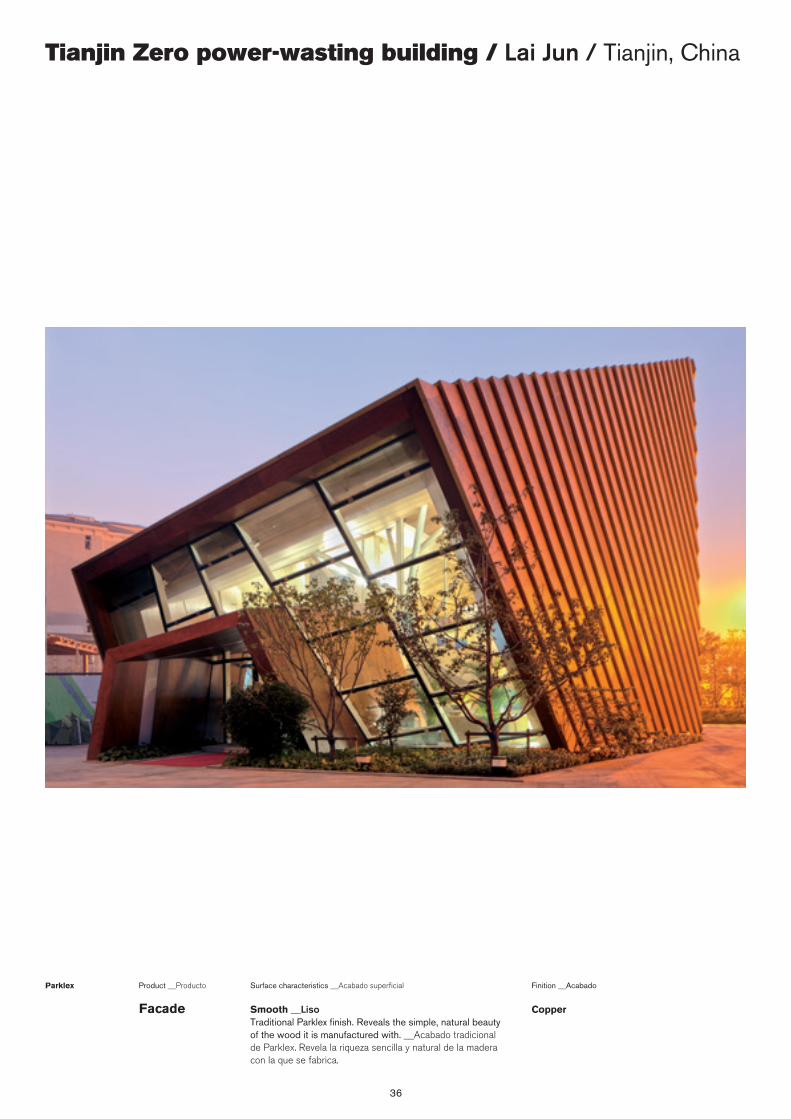
36
Tianjin Zero power-wasting building / Lai Jun / Tianjin, China
Surface characteristics __Acabado superficialProduct __Producto
Smooth __Liso Traditional Parklex finish. Reveals the simple, natural beauty of the wood it is manufactured with. __Acabado tradicional de Parklex. Revela la riqueza sencilla y natural de la madera con la que se fabrica.
Parklex Finition __Acabado
CopperFacade
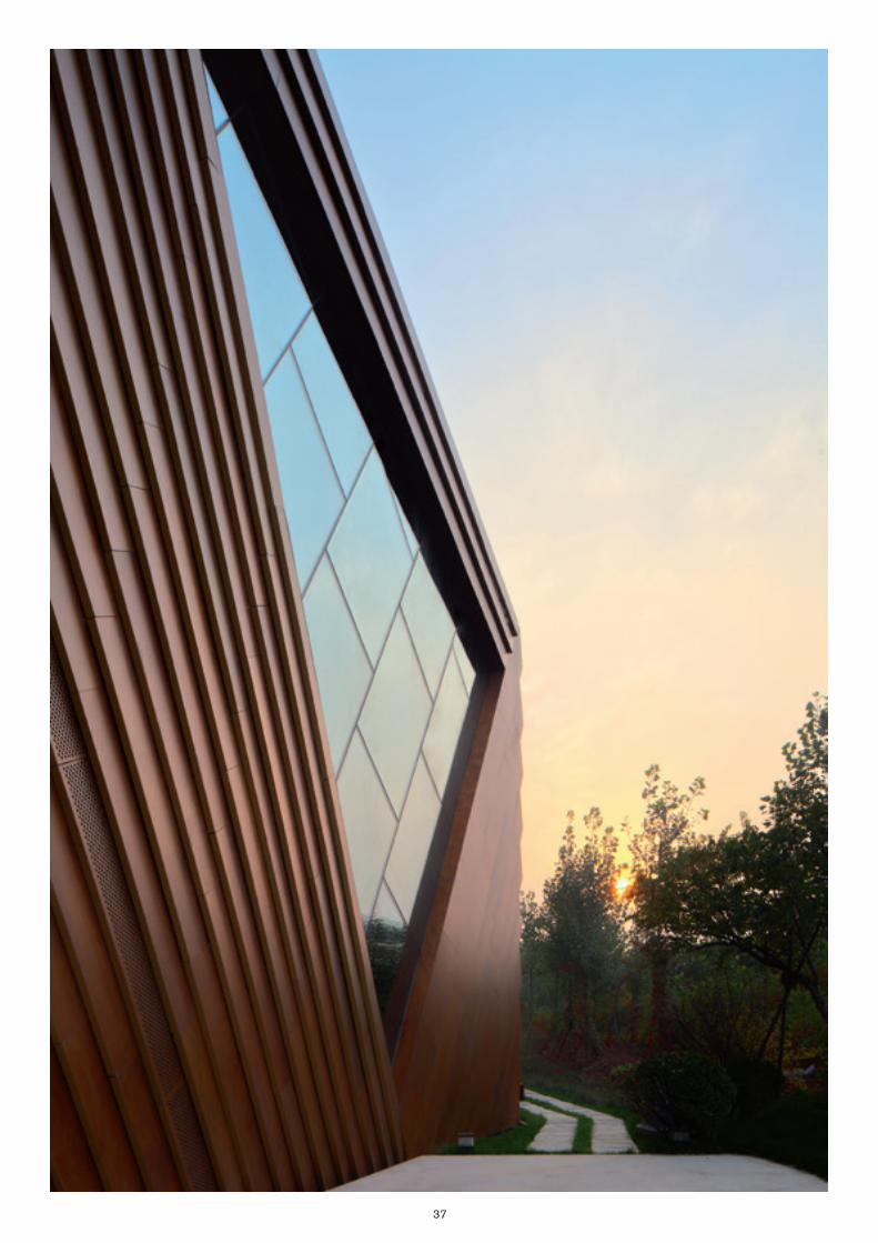
37
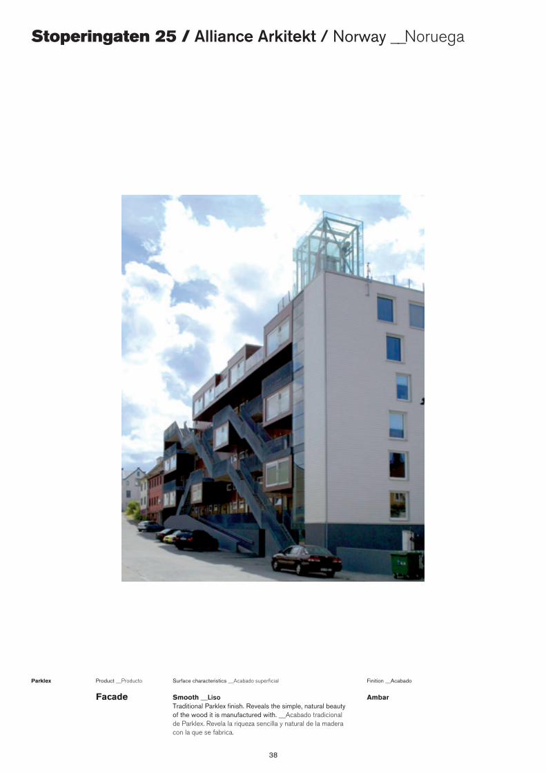
38
Stoperingaten 25 / Alliance Arkitekt / Norway __Noruega
Surface characteristics __Acabado superficialProduct __Producto
Smooth __Liso Traditional Parklex finish. Reveals the simple, natural beauty of the wood it is manufactured with. __Acabado tradicional de Parklex. Revela la riqueza sencilla y natural de la madera con la que se fabrica.
Parklex Finition __Acabado
AmbarFacade
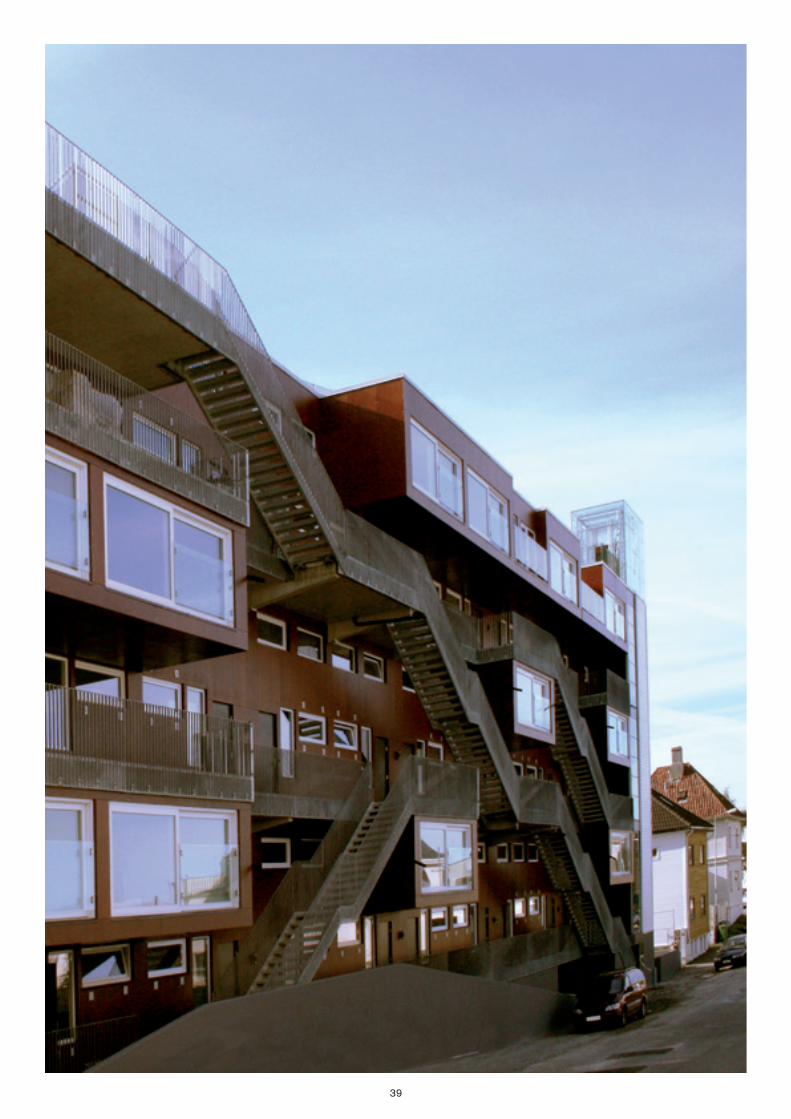
39
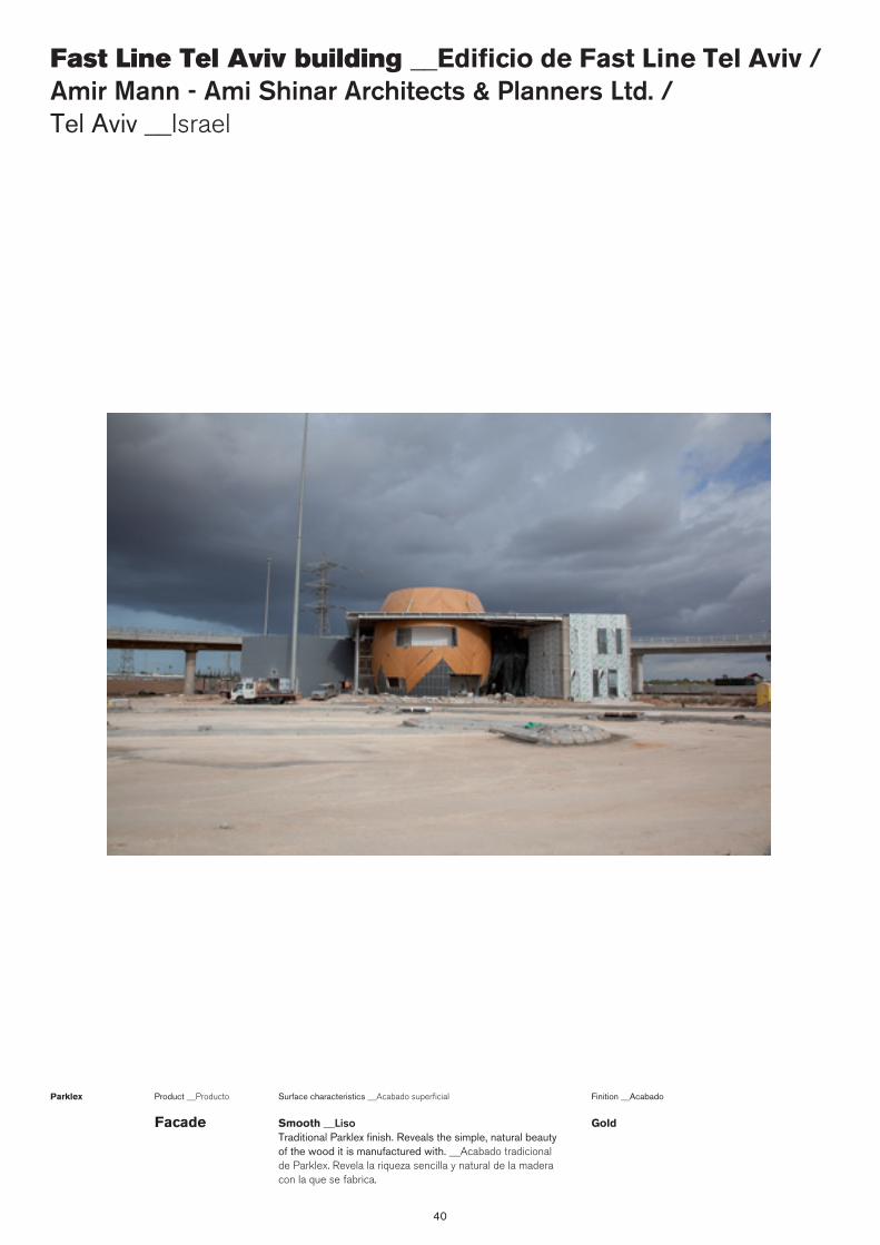
40
Fast Line Tel Aviv building __Edificio de Fast Line Tel Aviv / Amir Mann - Ami Shinar Architects & Planners Ltd. / Tel Aviv __Israel
Surface characteristics __Acabado superficialProduct __Producto
Smooth __Liso Traditional Parklex finish. Reveals the simple, natural beauty of the wood it is manufactured with. __Acabado tradicional de Parklex. Revela la riqueza sencilla y natural de la madera con la que se fabrica.
Parklex Finition __Acabado
GoldFacade
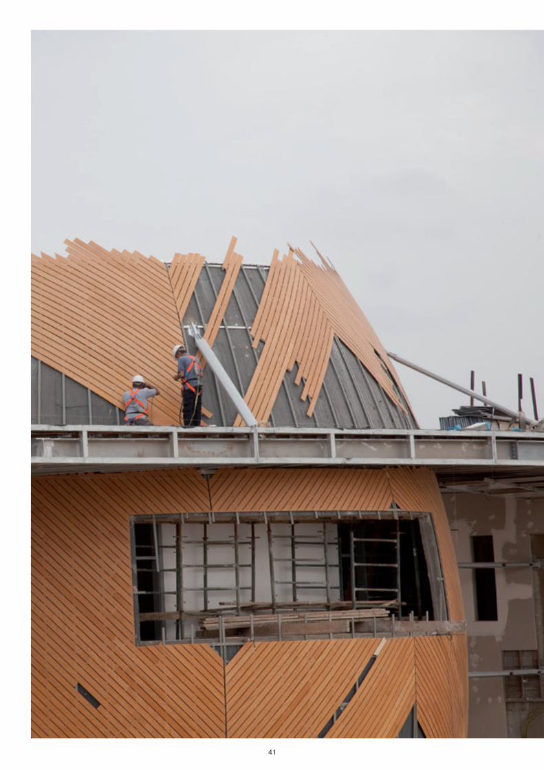
41
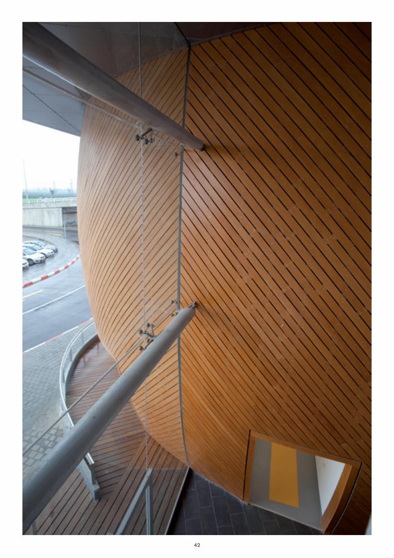
42
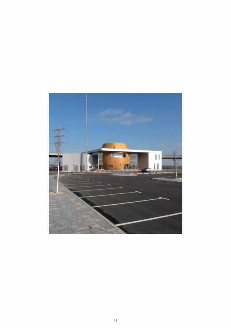
43

44
House in Cyprus __Casa en Chipre / Simpraxis Architects / Cyprus __Chipre
Surface characteristics __Acabado superficialProduct __Producto
Smooth __Liso Traditional Parklex finish. Reveals the simple, natural beauty of the wood it is manufactured with. __Acabado tradicional de Parklex. Revela la riqueza sencilla y natural de la madera con la que se fabrica.
Parklex Finition __Acabado
GoldFacade

45
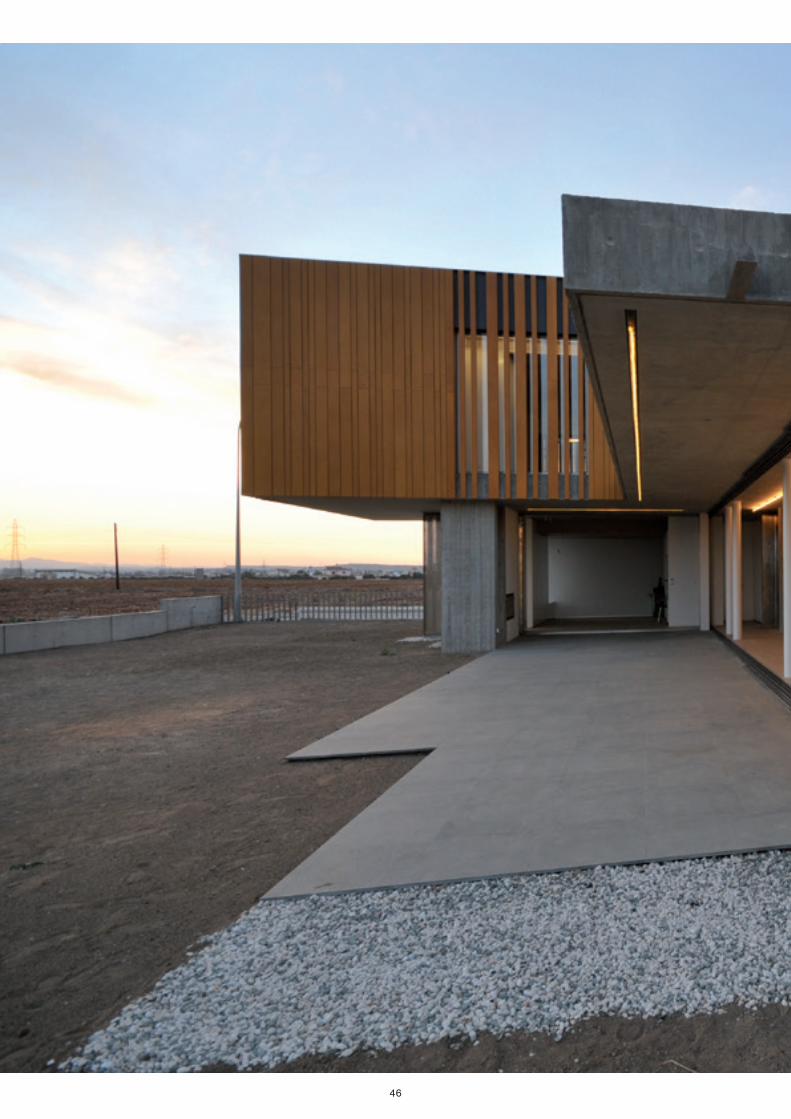
46
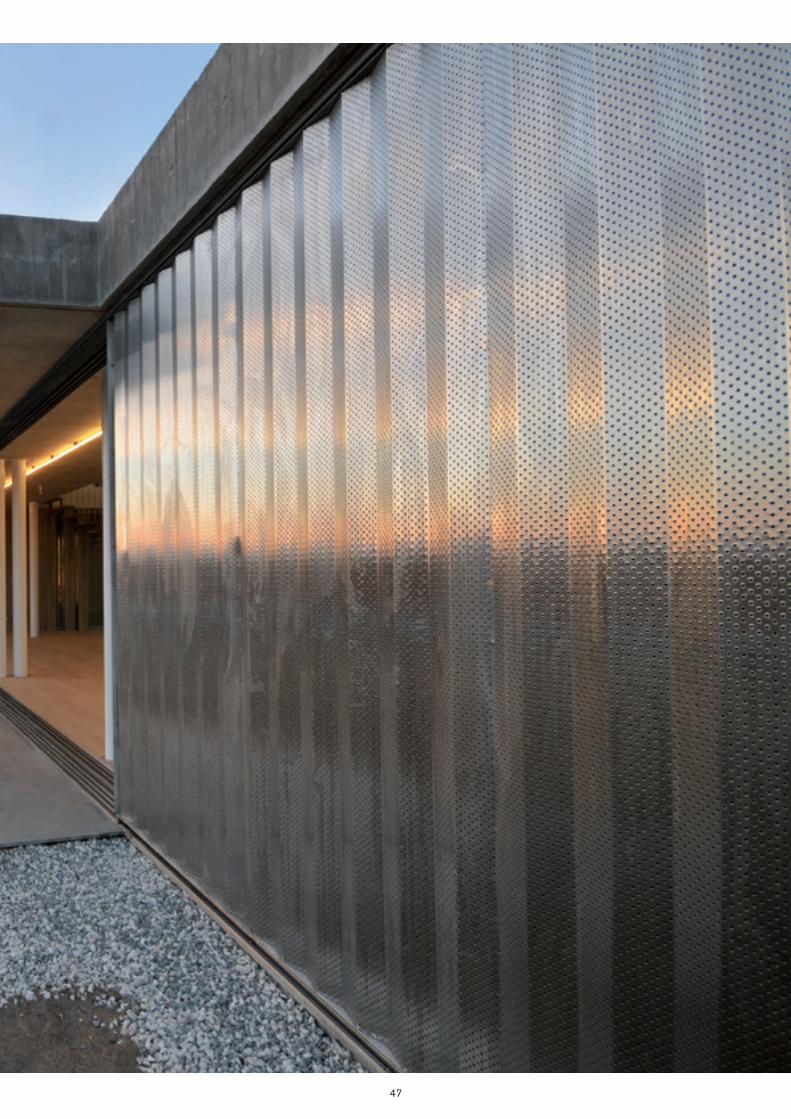
47
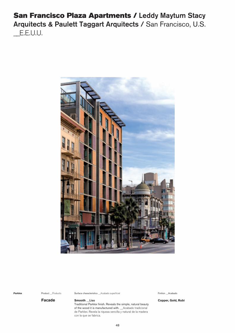
48
San Francisco Plaza Apartments / Leddy Maytum Stacy Arquitects & Paulett Taggart Arquitects / San Francisco, U.S. __E.E.U.U.
Surface characteristics __Acabado superficialProduct __Producto
Smooth __Liso Traditional Parklex finish. Reveals the simple, natural beauty of the wood it is manufactured with. __Acabado tradicional de Parklex. Revela la riqueza sencilla y natural de la madera con la que se fabrica.
Parklex Finition __Acabado
Copper, Gold, RubiFacade
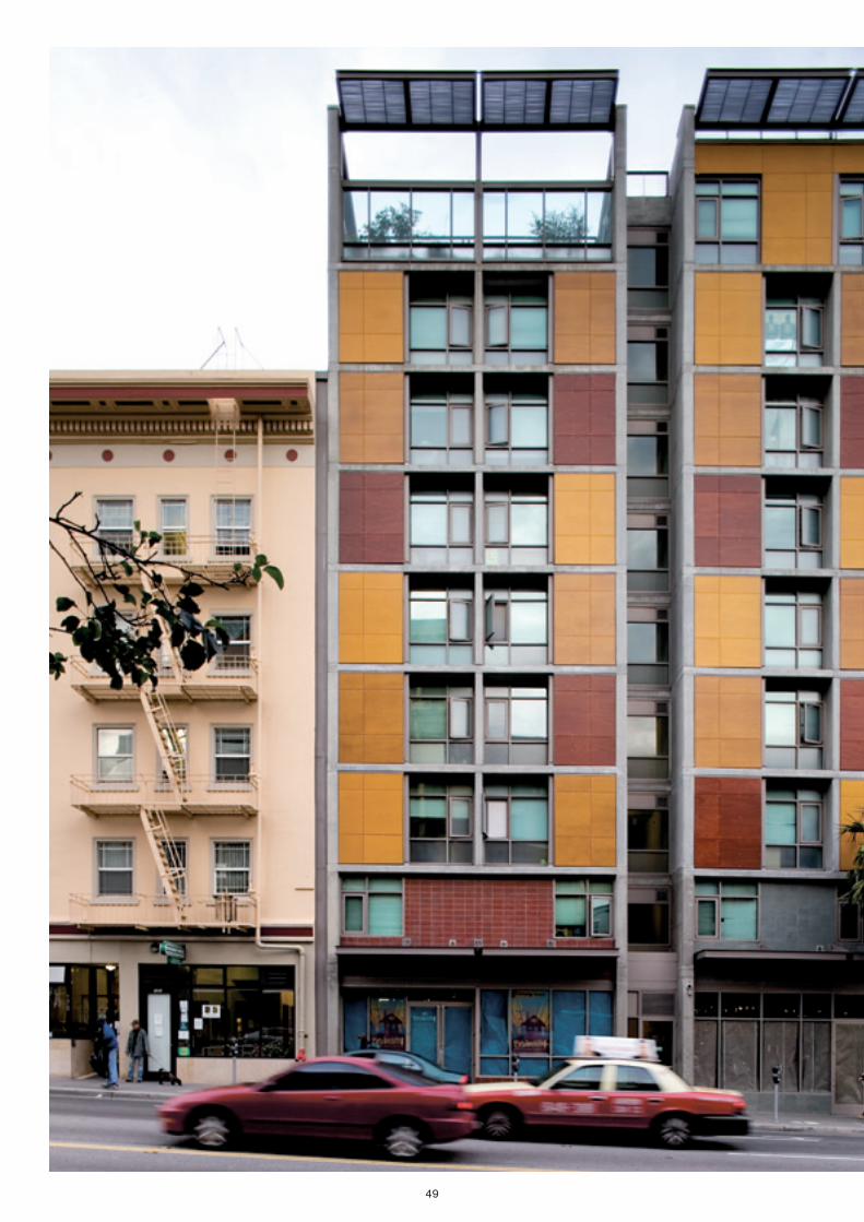
49
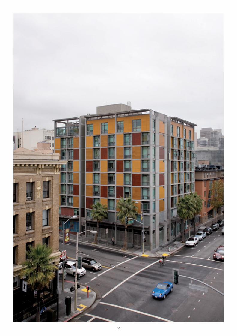
50

A responsible production
Parklex’s constant work and dedication in all areas of development and production are combined to offer a product and service that
meets the standards of even the most demanding architects. The ad-vantages offered by Parklex are evident from the moment it is insta-
lled, up to its long-term maintenance.
Parklex products can be used both indoors and outdoors, where they are subjected to constant wear from sunlight, moisture and abrasion
in traffic areas. Accordingly, a large part of the R+D effort and in-vestment is assigned to guaranteeing the durability and stability of
Parklex facings.
Our concern for sustainable production that is respectful of the envi-ronment has earned Parklex the guarantee of PEFC certification. This prestigious Chain of Custody certification guarantees Parklex’s con-
tribution to sustainable maintenance and improvement of forests and the environment.
With this certification Parklex proves its commit ment to responsible, eco-friendly growth. In addition, all the innovations included in the
new product ranges launched conform to this philosophy of respect for the environment and sustainable production that guarantees re-
source availability for many years to come.

Una producción responsable
El trabajo y la dedicación constante de Parklex en todos los ámbitos del desarrollo y de la producción, se conjugan para lograr ofrecer un pro-
ducto y un servicio de calidad. Parklex ofrece ventajas fundamentales, no solo en la calidad y el rendimiento de sus productos, sino también en el
momento de su instalación y su mantenimiento a lo largo del tiempo.
Los productos Parklex son aplicables tanto en el exterior como en el interior y están sometidos a constante desgaste producido por el sol, la humedad o la abrasión en zona de tránsito. Por ello, gran parte de los
esfuerzos e inversiones en I+D se destinan a garantizar la durabilidad e inalterabilidad de los revestimientos Parklex.
La preocupación por una producción sostenible y respetuosa con el me-dio ambiente ha permitido que Parklex cuente con la certificación PEFC que lo garantiza. Esta prestigiosa certificación de la cadena de custodia,
garantiza que Parklex está colaborando con el mantenimiento sostenible y mejora de los bosques y del medio ambiente.
Con esta certificación, Parklex demuestra su apuesta por un crecimiento responsable y no dañino para la naturaleza. Además, todas las inno-
vaciones que incorporan las nuevas gamas de producto que se lanzan siguen esta filosofía de respeto del medio ambiente y de producción
sostenible que garantice los recursos durante muchos años.
Production process __Proceso productivoEach type of Parklex is subjected to a different production process,
depending on its final application: interiors, exteriors, damp areas, etc.The base is always high-density laminated wood with a paper fiber core that has been treated with thermosetting resins and compressed at high
pressure and temperature. __Cada tipo de Parklex es sometido a un proceso de producción diferente en función de la aplicación final: interior,
exterior, zonas húmedas, etc. La base es siempre un estratificado de madera de alta densidad constituido interiormente por fibras de papel tratadas con resinas termoendurecidas y comprimidas a altas presiones y temperaturas.
Natural wood __Madera naturalThe surface is always made from 100% natural wood, treated according
to its application: to resist special weather conditions or to perfectly resist the intensive use it might receive in interiors. __La cara superficial es
siempre de madera 100% natural, tratada de manera diferente en función de su aplicación: para resistir las especiales exigencias de intemperie o
para aguantar perfectamente el uso intensivo al que se puede ver sometida en el interior.
Finishes __AcabadosPerfect adaptation to the project design is an essential requirement.
That’s why the technology used to manufacture Parklex allows us to apply different finishes, all in natural wood, to integrate them completely into the environment that is required for each project. __Adaptarse perfectamente
al diseño del proyecto es un requisito imprescindible. Así, la tecnología empleada en la fabricación de Parklex permite realizar diferentes acabados,
todos ellos de madera natural, para integrarse totalmente en el ambiente requerido en cada zona.
Range __GamaThe variety of finishes and colors in natural and dyed panels sets Parklex
apart as a result of its versatility, making it the ideal covering from any type of project. __La variedad de acabados y colores en chapa natural y teñida diferencia a Parklex por su versatilidad, haciéndolo el revestimiento ideal
para cualquier tipo de proyecto.
International __InternacionalProviding service on an international level has meant establishing an
extensive network of Parklex distributors on all five continents. This allows us to work more closely with our clients and offer them better service in a way that is more accessible to them. It also lets us understand their needs perfectly and first hand. __Dar servicio a escala internacional ha requerido disponer de una extensa red de distribuidores de Parklex que abarca los
cinco continentes. Ésto posibilita trabajar más cerca de nuestros clientes y ofrecerles así un servicio mejor y más cercano, además de que nos permite
conocer perfectamente y de primera mano sus necesidades.
Guarantees / Quality certificates __Garantía / Certificados de calidad
Rigorous testing guarantees Parklex’s excellent performance. __Rigurosas pruebas garantizan el buen comportamiento de Parklex.
ER-0370/2003 GA-2011/0535


Fac
ade
Par
klex
201
4
FacadeTechnical guide __Guía técnica
Facade is a high density laminate timber panel for outdoor cladding. For a correct panel installation it is important to follow the general instructions described along this docu-ment. __Facade es un tablero estratificado de madera de alta densidad para revestimiento de exteriores. Para una perfecta instalación de los paneles es importante seguir las instruc-
ciones generales descritas a lo largo de este documento.
Timber in architecture __Madera y arquitectura

1. About Facade __Acerca de Facade
1.1. Product features __Características del producto 9
1.1.1. Product quality and certificates __Calidad de producto y certificaciones 9
1.1.2. Environmental sustainability __Sostenibilidad y gestión ambiental 9
1.1.3. Technical datasheet __Ficha técnica 10
1.2. Transport __Transporte 12
1.3. Storage __Almacenamiento 12
1.4. Handling __Manipulación 13
1.4.1. Cutting __Corte 13
1.4.2. Drilling __Taladrado 13
1.4.3. Machining __Mecanizado 13
1.5. Cleaning and maintenance __Limpieza y mantenimiento 14
1.5.1. Cleaning __Limpieza 14
1.5.2. Maintenance __Mantenimiento 14
1.5.3. Repair __Reparación 14
1.6. Information for removal __Información para la desinstalación 15
1.6.1. Waste management information __Información a los gestores de residuos 15
2. General Instructions __Instrucciones Generales
2.1. Humidity and temperature __Humedad y temperatura 18
2.2. Expansion joints __Juntas de dilatación 19
2.3. Choosing panel thickness __Elección del espesor del panel 19
2.4. Three support points __Tres puntos de apoyo 20
2.5. Counter-sunk screws not allowed __No permitidos tornillos de cabeza avellanada 20
3. Installation system on ventilated façade __Sistema de insta-lación en fachada ventilada
3.1. Ventilated chamber __Cámara Ventilada 24
3.2. Substructure __Subestructura 26
3.3. Fixing systems __Sistemas de fijación 27
3.3.1. Exposed screw or rivet fixing __Fijación vista con tornillo o remache 27
3.3.2. Fixing with plugs __Fijación oculta con tapones 30
3.3.3. Hidden fixing with bracket hanging system __Fijación oculta con sistema de cuelgue 31
3.3.4. Hidden fixing with an adhesive system __Fijación oculta adhesivo 33
3.3.5. Hidden fixing with overlapping slats __Fijación oculta con lama solapada 34
3.4. Installation details __Detalles de instalación 36
3.4.1. Window details __Detalles de ventana 36
3.4.2. Corner details __Detalles de esquina 37
4. Louvre installation system __Sistema de instalación en celosías
4.1. Static louvres __Celosías fijas 42
4.1.1. Substructure __Subestructura 43
4.1.2. Substructure installation __Instalación de la subestructura 43
4.1.3. Supporting clip installation __Instalación del clip soporte 44
4.1.4. Louvre installation __Instalación de la celosía 45
4.2. Mobile louvres __Celosías móviles 43
5. Dropped ceiling installation system __Sistema de instalación en falsos techos
5.1. Fixing the dropped ceiling __Fijación del falso techo 48
5.2.1. Screw or rivet fixing __Fijación con tornillo o remache 48
6. Installation system in curves __Sistema de instalación en curvas
6.1. Panel curving ___Curvado de paneles 54
6.2. Pre-curved panels ___Paneles pre-curvados 54
6.3. Pre-curved panel installation __Instalación de los paneles pre-curvados 55
6.3.1. Exposed screw or rivet fixing __Fijación vista con tornillo o remache 55
6.4. Technical datasheet __Ficha técnica 56


1. About Facade __Acerca Facade
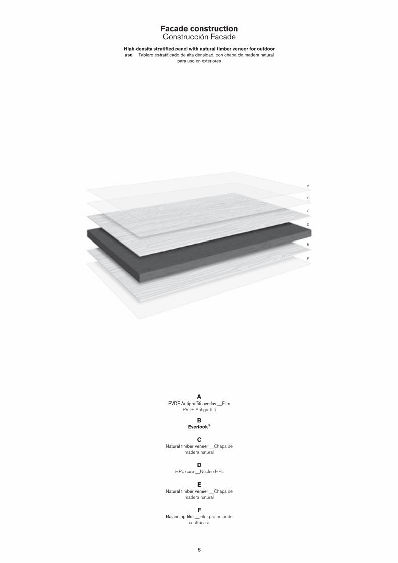
8
Facade constructionConstrucción Facade
High-density stratified panel with natural timber veneer for outdoor use __Tablero estratificado de alta densidad, con chapa de madera natural
para uso en exteriores
A
B
C
D
E
F
APVDF Antigraffiti overlay __Film
PVDF Antigraffiti
BEverlook®
CNatural timber veneer __Chapa de
madera natural
DHPL core __Núcleo HPL
ENatural timber veneer __Chapa de
madera natural
FBalancing film __Film protector de
contracara
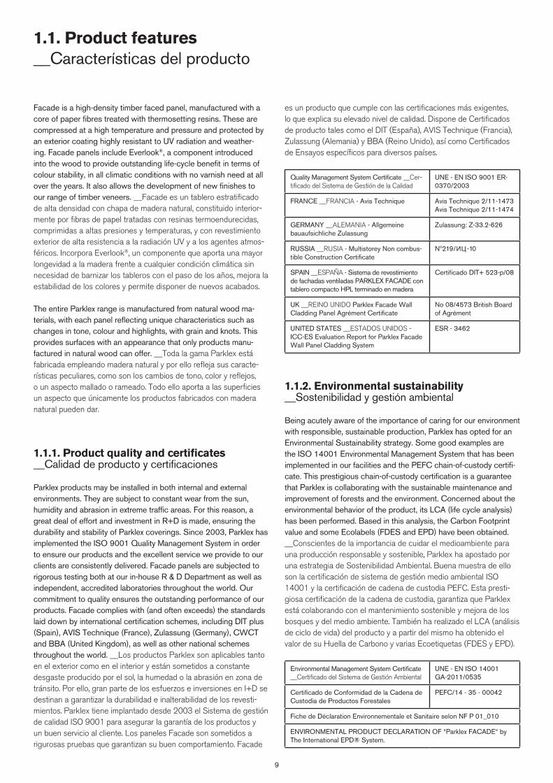
98
1.1. Product features __Características del producto
es un producto que cumple con las certificaciones más exigentes, lo que explica su elevado nivel de calidad. Dispone de Certificados de producto tales como el DIT (España), AVIS Technique (Francia), Zulassung (Alemania) y BBA (Reino Unido), así como Certificados de Ensayos específicos para diversos países.
Quality Management System Certificate __Cer-tificado del Sistema de Gestión de la Calidad
UNE - EN ISO 9001 ER-0370/2003
FRANCE __FRANCIA - Avis Technique Avis Technique 2/11-1473 Avis Technique 2/11-1474
GERMANY __ALEMANIA - Allgemeine bauaufsichliche Zulassung
Zulassung: Z-33.2-626
RUSSIA __RUSIA - Multistorey Non combus-tible Construction Certificate
Nº219/ИЦ -10
SPAIN __ESPAÑA - Sistema de revestimiento de fachadas ventiladas PARKLEX FACADE con tablero compacto HPL terminado en madera
Certificado DIT+ 523-p/08
UK __REINO UNIDO Parklex Facade Wall Cladding Panel Agrément Certificate
No 08/4573 British Board of Agrément
UNITED STATES __ESTADOS UNIDOS - ICC-ES Evaluation Report for Parklex Facade Wall Panel Cladding System
ESR - 3462
1.1.2. Environmental sustainability __Sostenibilidad y gestión ambiental
Being acutely aware of the importance of caring for our environment with responsible, sustainable production, Parklex has opted for an Environmental Sustainability strategy. Some good examples are the ISO 14001 Environmental Management System that has been implemented in our facilities and the PEFC chain-of-custody certifi-cate. This prestigious chain-of-custody certification is a guarantee that Parklex is collaborating with the sustainable maintenance and improvement of forests and the environment. Concerned about the environmental behavior of the product, its LCA (life cycle analysis) has been performed. Based in this analysis, the Carbon Footprint value and some Ecolabels (FDES and EPD) have been obtained. __Conscientes de la importancia de cuidar el medioambiente para una producción responsable y sostenible, Parklex ha apostado por una estrategia de Sostenibilidad Ambiental. Buena muestra de ello son la certificación de sistema de gestión medio ambiental ISO 14001 y la certificación de cadena de custodia PEFC. Esta presti-giosa certificación de la cadena de custodia, garantiza que Parklex está colaborando con el mantenimiento sostenible y mejora de los bosques y del medio ambiente. También ha realizado el LCA (análisis de ciclo de vida) del producto y a partir del mismo ha obtenido el valor de su Huella de Carbono y varias Ecoetiquetas (FDES y EPD).
Environmental Management System Certificate __Certificado del Sistema de Gestión Ambiental
UNE - EN ISO 14001 GA-2011/0535
Certificado de Conformidad de la Cadena de Custodia de Productos Forestales
PEFC/14 - 35 - 00042
Fiche de Déclaration Environnementale et Sanitaire selon NF P 01_010
ENVIRONMENTAL PRODUCT DECLARATION OF “Parklex FACADE“ by The International EPD® System.
Facade is a high-density timber faced panel, manufactured with a core of paper fibres treated with thermosetting resins. These are compressed at a high temperature and pressure and protected by an exterior coating highly resistant to UV radiation and weather-ing. Facade panels include Everlook®, a component introduced into the wood to provide outstanding life-cycle benefit in terms of colour stability, in all climatic conditions with no varnish need at all over the years. It also allows the development of new finishes to our range of timber veneers. __Facade es un tablero estratificado de alta densidad con chapa de madera natural, constituido interior-mente por fibras de papel tratadas con resinas termoendurecidas, comprimidas a altas presiones y temperaturas, y con revestimiento exterior de alta resistencia a la radiación UV y a los agentes atmos-féricos. Incorpora Everlook®, un componente que aporta una mayor longevidad a la madera frente a cualquier condición climática sin necesidad de barnizar los tableros con el paso de los años, mejora la estabilidad de los colores y permite disponer de nuevos acabados.
The entire Parklex range is manufactured from natural wood ma-terials, with each panel reflecting unique characteristics such as changes in tone, colour and highlights, with grain and knots. This provides surfaces with an appearance that only products manu-factured in natural wood can offer. __Toda la gama Parklex está fabricada empleando madera natural y por ello refleja sus caracte-rísticas peculiares, como son los cambios de tono, color y reflejos, o un aspecto mallado o rameado. Todo ello aporta a las superficies un aspecto que únicamente los productos fabricados con madera natural pueden dar.
1.1.1. Product quality and certificates __Calidad de producto y certificaciones
Parklex products may be installed in both internal and external environments. They are subject to constant wear from the sun, humidity and abrasion in extreme traffic areas. For this reason, a great deal of effort and investment in R+D is made, ensuring the durability and stability of Parklex coverings. Since 2003, Parklex has implemented the ISO 9001 Quality Management System in order to ensure our products and the excellent service we provide to our clients are consistently delivered. Facade panels are subjected to rigorous testing both at our in-house R & D Department as well as independent, accredited laboratories throughout the world. Our commitment to quality ensures the outstanding performance of our products. Facade complies with (and often exceeds) the standards laid down by international certification schemes, including DIT plus (Spain), AVIS Technique (France), Zulassung (Germany), CWCT and BBA (United Kingdom), as well as other national schemes throughout the world. __Los productos Parklex son aplicables tanto en el exterior como en el interior y están sometidos a constante desgaste producido por el sol, la humedad o la abrasión en zona de tránsito. Por ello, gran parte de los esfuerzos e inversiones en I+D se destinan a garantizar la durabilidad e inalterabilidad de los revesti-mientos. Parklex tiene implantado desde 2003 el Sistema de gestión de calidad ISO 9001 para asegurar la garantía de los productos y un buen servicio al cliente. Los paneles Facade son sometidos a rigurosas pruebas que garantizan su buen comportamiento. Facade
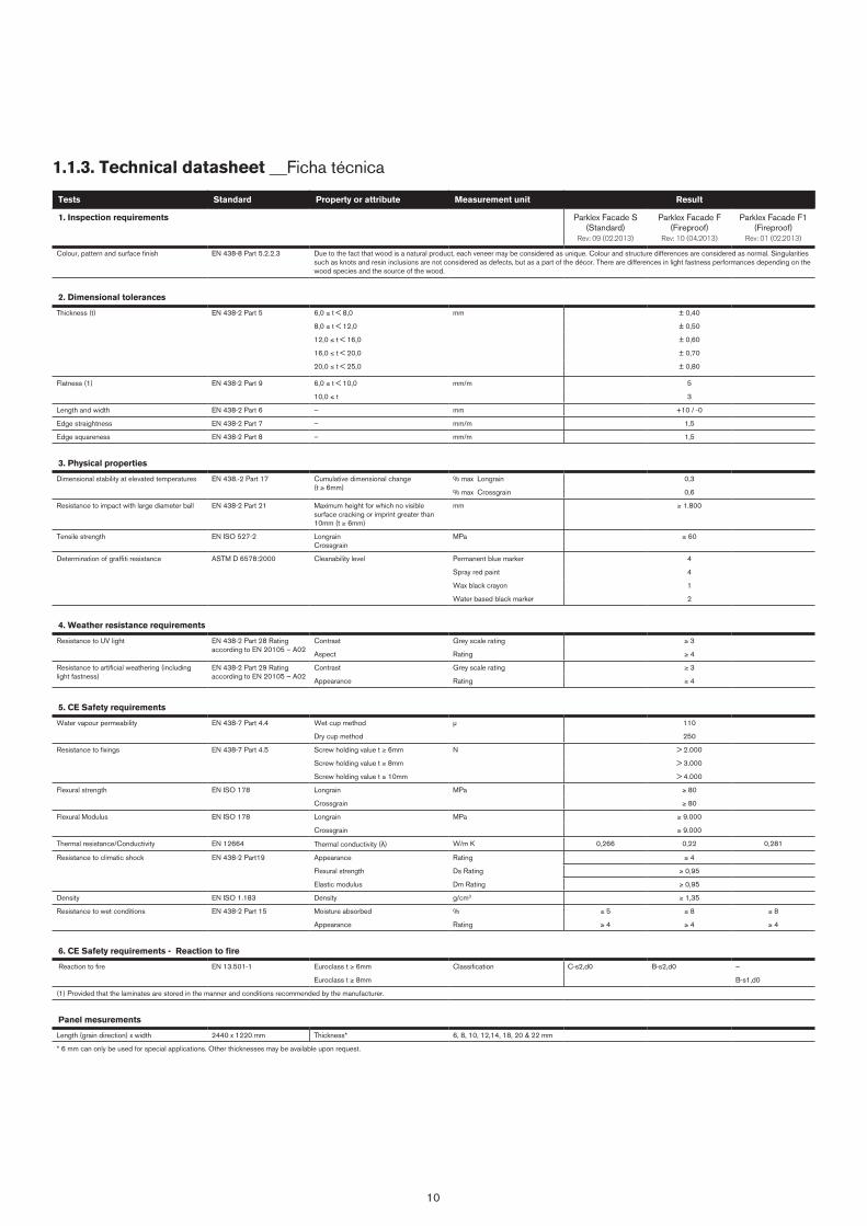
10
1.1.3. Technical datasheet __Ficha técnica
Tests Standard Property or attribute Measurement unit Result
1. Inspection requirements Parklex Facade S(Standard)
Rev: 09 (02.2013)
Parklex Facade F(Fireproof)
Rev: 10 (04.2013)
Parklex Facade F1(Fireproof)
Rev: 01 (02.2013)
Colour, pattern and surface finish EN 438-8 Part 5.2.2.3 Due to the fact that wood is a natural product, each veneer may be considered as unique. Colour and structure differences are considered as normal. Singularities such as knots and resin inclusions are not considered as defects, but as a part of the décor. There are differences in light fastness performances depending on the wood species and the source of the wood.
2. Dimensional tolerances
Thickness (t) EN 438-2 Part 5 6,0 ≤ t < 8,0 mm ± 0,40
8,0 ≤ t < 12,0 ± 0,50
12,0 ≤ t < 16,0 ± 0,60
16,0 ≤ t < 20,0 ± 0,70
20,0 ≤ t < 25,0 ± 0,80
Flatness (1) EN 438-2 Part 9 6,0 ≤ t < 10,0 mm/m 5
10,0 ≤ t 3
Length and width EN 438-2 Part 6 – mm +10 / -0
Edge straightness EN 438-2 Part 7 – mm/m 1,5
Edge squareness EN 438-2 Part 8 – mm/m 1,5
3. Physical properties
Dimensional stability at elevated temperatures EN 438.-2 Part 17 Cumulative dimensional change(t ≥ 6mm)
% max Longrain 0,3
% max Crossgrain 0,6
Resistance to impact with large diameter ball EN 438-2 Part 21 Maximum height for which no visible surface cracking or imprint greater than 10mm (t ≥ 6mm)
mm ≥ 1.800
Tensile strength EN ISO 527-2 LongrainCrossgrain
MPa ≥ 60
Determination of graffiti resistance ASTM D 6578:2000 Cleanability level Permanent blue marker 4
Spray red paint 4
Wax black crayon 1
Water based black marker 2
4. Weather resistance requirements
Resistance to UV light EN 438-2 Part 28 Rating according to EN 20105 – A02
Contrast Grey scale rating ≥ 3
Aspect Rating ≥ 4
Resistance to artificial weathering (including light fastness)
EN 438-2 Part 29 Rating according to EN 20105 – A02
Contrast Grey scale rating ≥ 3
Appearance Rating ≥ 4
5. CE Safety requirements
Water vapour permeability EN 438-7 Part 4.4 Wet cup method µ 110
Dry cup method 250
Resistance to fixings EN 438-7 Part 4.5 Screw holding value t ≥ 6mm N > 2.000
Screw holding value t ≥ 8mm > 3.000
Screw holding value t ≥ 10mm > 4.000
Flexural strength EN ISO 178 Longrain MPa ≥ 80
Crossgrain ≥ 80
Flexural Modulus EN ISO 178 Longrain MPa ≥ 9.000
Crossgrain ≥ 9.000
Thermal resistance/Conductivity EN 12664 Thermal conductivity ( ) W/m K 0,266 0,22 0,281
Resistance to climatic shock EN 438-2 Part19 Appearance Rating ≥ 4
Flexural strength Ds Rating ≥ 0,95
Elastic modulus Dm Rating ≥ 0,95
Density EN ISO 1.183 Density g/cm3 ≥ 1,35
Resistance to wet conditions EN 438-2 Part 15 Moisture absorbed % ≤ 5 ≤ 8 ≤ 8
Appearance Rating ≥ 4 ≥ 4 ≥ 4
6. CE Safety requirements - Reaction to fire
Reaction to fire EN 13.501-1 Euroclass t ≥ 6mm Classification C-s2,d0 B-s2,d0 –
Euroclass t ≥ 8mm B-s1,d0
(1) Provided that the laminates are stored in the manner and conditions recommended by the manufacturer.
Panel mesurements
Length (grain direction) x width 2440 x 1220 mm Thickness* 6, 8, 10, 12,14, 18, 20 & 22 mm
* 6 mm can only be used for special applications. Other thicknesses may be available upon request.
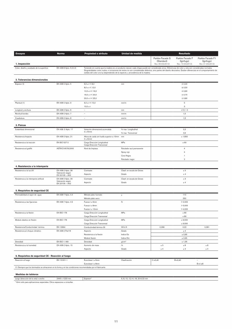
11
Ensayos Norma Propiedad o atributo Unidad de medida Resultado
1. Inspección
Parklex Facade S(Standard)
Rev: 09 (02.2013)
Parklex Facade F(Ignífugo)
Rev: 10 (04.2013)
Parklex Facade F1(Ignífugo)
Rev: 01 (02.2013)
Color, diseño y acabado de la superficie EN 438-8 Apto. 5.2.2.3 Teniendo en cuenta que la madera es un producto natural, cada chapa puede ser considerada única. Diferencias de color y veta son consideradas normales. Singularidades como nudos, e inclusiones de resina no son consideradas defectos, sino partes del diseño decorativo. Existen diferencias en el comportamiento de solidez del color a la luz dependiendo de la especie y procedencia de la madera.
2. Tolerancias dimensionales
Espesor (t) EN 438-2 Apto. 5 6,0 ≤ t < 8,0 mm ± 0,40
8,0 ≤ t < 12,0 ± 0,50
12,0 ≤ t < 16,0 ± 0,60
16,0 ≤ t < 20,0 ± 0,70
20,0 ≤ t < 25,0 ± 0,80
Planitud (1) EN 438-2 Apto. 9 6,0 ≤ t < 10,0 mm/m 5
10,0 ≤ t 3
Longitud y anchura EN 438-2 Apto. 6 – mm +10 / -0
Rectitud bordes EN 438-2 Apto. 7 – mm/m 1,5
Cuadratura EN 438-2 Apto. 8 – mm/m 1,5
3. Fisicas
Estabilidad dimensional EN 438.-2 Apto. 17 Variación dimensional acumulada(t ≥ 6mm)
% max Longitudinal 0,3
% max Transversal 0,6
Resistencia Impacto EN 438-2 Apto. 21 Altura de caída sin huella superior a 10mm (t ≥ 6mm)
mm ≥ 1.800
Resistencia a la tracción EN ISO 527-2 Carga Dirección LongitudinalCarga Dirección Transversal
MPa ≥ 60
Resistencia al graffiti ASTM D 6578:2000 Nivel de limpieza Rotulador azul permanente 4
Spray rojo 4
Cera Negra 1
Rotulador negro 2
4. Resistencia a la intemperie
Resistencia a la luz UV EN 438-2 Apto. 28 Valoración según EN 20105 – A02
Contraste Clasif. en escala de Grises ≥ 3
Aspecto Grado ≥ 4
Resistencia a la intemperie artificial EN 438-2 Apto. 29 Valoración según EN 20105 – A02
Contraste Clasif. en escala de Grises ≥ 3
Aspecto Grado ≥ 4
5. Requisitos de seguridad CE
Permeabilidad al vapor de agua EN 438-7 Apto. 4.4 Método plato húmedo µ 110
Método plato seco 250
Resistencia a las fijaciones EN 438-7 Apto. 4.5 Fuerza t ≥ 6mm N > 2.000
Fuerza t ≥ 8mm > 3.000
Fuerza t ≥ 10mm > 4.000
Resistencia a la flexión EN ISO 178 Carga Dirección Longitudinal MPa ≥ 80
Carga Dirección Transversal ≥ 80
Módulo elástico en flexión EN ISO 178 Carga Dirección Longitudinal MPa ≥ 9.000
Carga Dirección Transversal ≥ 9.000
Resistencia/Conductividad térmica EN 12664 Conductividad térmica ( ) W/m K 0,266 0,22 0,281
Resistencia al choque climático EN 438-2 Part19 Aspecto Grado ≥ 4
Resistencia a la flexión Indice Ds ≥ 0,95
Módulo flexión Indice Dm ≥ 0,95
Densidad EN ISO 1.183 Densidad g/cm3 ≥ 1,35
Resistencia a la humedad EN 438-2 Apto. 15 Aumento de masa % ≤ 5 ≤ 8 ≤ 8
Aspecto Grado ≥ 4 ≥ 4 ≥ 4
6. Requisitos de seguridad CE - Reacción al fuego
Reacción al fuego EN 13.501-1 Euroclase t ≥ 6mm Clasificación C-s2,d0 B-s2,d0 –
Euroclase t ≥ 8mm B-s1,d0
(1) Siempre que los laminados se almacenen en la forma y en las condiciones recomendadas por el fabricante.
Medidas de tableros
Largo (dirección de la veta) x ancho 2440 x 1220 mm Espesor* 6, 8, 10, 12,14, 18, 20 & 22 mm
* 6mm sólo para aplicaciones especiales. Otros espesores a consultar.
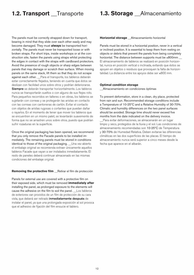
12
1.2. Transport __Transporte 1.3. Storage __Almacenamiento
The panels must be correctly strapped down for transport, bearing in mind that they slide over each other easily and may become damaged. They must always be transported hori-zontally. The panels must never be transported loose or with broken straps. For short trips, inside workshops or at the con-struction site, fasten the panels using straps whilst protecting the edges in contact with the straps with cardboard protectors. Avoid the presence of rough objects or sharp edges between panels that may damage or scratch their surface. When moving panels on the same stack, lift them so that they do not scrape against each other. __Para el transporte, los tableros deberán estar correctamente flejados, teniendo en cuenta que éstos se deslizan con facilidad unos sobre otros y podrían deteriorarse. Siempre se deberán transportar horizontalmente. Los tableros nunca se transportarán sueltos o con alguno de sus flejes roto. Para pequeños recorridos en talleres o en obras, los tableros se sujetarán con correas y se protegerán las aristas en contacto con las correas con cantoneras de cartón. Evitar el contacto con objetos de aristas rugosas o cortantes que puedan dañar o rayarlos. En el momento de tener que mover los tableros que se encuentren en un mismo palet, se levantarán suavemente de forma que no se arrastren unos sobre otros, puesto que podrían sufrir rozaduras en la superficie.
Once the original packaging has been opened, we recommend that you only remove the Facade panels to be installed im-mediately. The remaining panels must be stored in conditions identical to those of the original packaging. __Una vez abierto el embalaje original se recomienda extraer únicamente aquellos tableros Facade que vayan a ser instalados inmediatamente. El resto de paneles deberá continuar almacenado en las mismas condiciones del embalaje original.
Removing the protective film __Retirar el film de protección
Panels for external use are covered with a protective film on their exposed side, which must be removed immediately after installing the panel, as prolonged exposure to the elements will cause the adhesive on the film to soil the panel. __Los tableros de exteriores van provistos de un film de protección de su cara vista, que deberá ser retirado inmediatamente después de instalar el panel, ya que una prolongada exposición al sol provoca que el adhesivo de fijación del film ensucie el tablero.
Horizontal storage __Almacenamiento horizontal
Panels must be stored in a horizontal position, never in a vertical or inclined position. It is essential to keep them from resting on objects or debris that prevent the panels from being completely horizontal. The distance between supports must be ≤800mm __El almacenamiento de tableros se realizará en posición horizon-tal, nunca en posición vertical o inclinada, evitando que éstos se apoyen en objetos o residuos que provoquen la falta de horizon-talidad. La distancia entre los apoyos debe ser ≤800 mm.
Optimal condition storage __Almacenamiento en condiciones óptimas
To prevent deformation, store in a clean, dry place, protected from rain and sun. Recommended storage conditions include a Temperature of 10-25ºC and a Relative Humidity of 30-70%. Climatic and humidity differences on the two panel surfaces should be avoided. Storage time should never exceed five months from the date indicated on the delivery invoice. __Para evitar deformaciones, se almacenarán en un lugar limpio y seco, protegidos de la lluvia y el sol. Las condiciones de almacenamiento recomendadas son 10-25ºC de Temperatura y 30-70% de Humedad Relativa. Deben evitarse las diferencias climáticas en las dos superficies de las placas. El tiempo de almacenamiento nunca será superior a cinco meses desde la fecha que aparece en el albarán.
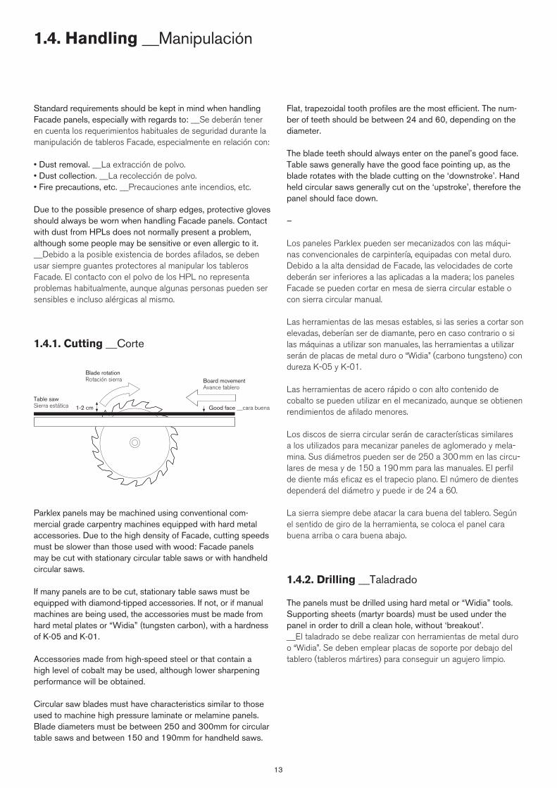
13
1.4. Handling __Manipulación
Standard requirements should be kept in mind when handling Facade panels, especially with regards to: __Se deberán tener en cuenta los requerimientos habituales de seguridad durante la manipulación de tableros Facade, especialmente en relación con:
• Dust removal. __La extracción de polvo.• Dust collection. __La recolección de polvo.• Fire precautions, etc. __Precauciones ante incendios, etc.
Due to the possible presence of sharp edges, protective gloves should always be worn when handling Facade panels. Contact with dust from HPLs does not normally present a problem, although some people may be sensitive or even allergic to it. __Debido a la posible existencia de bordes afilados, se deben usar siempre guantes protectores al manipular los tableros Facade. El contacto con el polvo de los HPL no representa problemas habitualmente, aunque algunas personas pueden ser sensibles e incluso alérgicas al mismo.
1.4.1. Cutting __Corte
1-2 cm
Blade rotationRotación sierra Board movement
Avance tablero
Table sawSierra estática Good face __cara buena
Parklex panels may be machined using conventional com-mercial grade carpentry machines equipped with hard metal accessories. Due to the high density of Facade, cutting speeds must be slower than those used with wood: Facade panels may be cut with stationary circular table saws or with handheld circular saws.
If many panels are to be cut, stationary table saws must be equipped with diamond-tipped accessories. If not, or if manual machines are being used, the accessories must be made from hard metal plates or “Widia” (tungsten carbon), with a hardness of K-05 and K-01.
Accessories made from high-speed steel or that contain a high level of cobalt may be used, although lower sharpening performance will be obtained.
Circular saw blades must have characteristics similar to those used to machine high pressure laminate or melamine panels. Blade diameters must be between 250 and 300mm for circular table saws and between 150 and 190mm for handheld saws.
Flat, trapezoidal tooth profiles are the most efficient. The num-ber of teeth should be between 24 and 60, depending on the diameter.
The blade teeth should always enter on the panel’s good face. Table saws generally have the good face pointing up, as the blade rotates with the blade cutting on the ‘downstroke’. Hand held circular saws generally cut on the ‘upstroke’, therefore the panel should face down.
–
Los paneles Parklex pueden ser mecanizados con las máqui-nas convencionales de carpintería, equipadas con metal duro. Debido a la alta densidad de Facade, las velocidades de corte deberán ser inferiores a las aplicadas a la madera; los paneles Facade se pueden cortar en mesa de sierra circular estable o con sierra circular manual.
Las herramientas de las mesas estables, si las series a cortar son elevadas, deberían ser de diamante, pero en caso contrario o si las máquinas a utilizar son manuales, las herramientas a utilizar serán de placas de metal duro o “Widia” (carbono tungsteno) con dureza K-05 y K-01.
Las herramientas de acero rápido o con alto contenido de cobalto se pueden utilizar en el mecanizado, aunque se obtienen rendimientos de afilado menores.
Los discos de sierra circular serán de características similares a los utilizados para mecanizar paneles de aglomerado y mela-mina. Sus diámetros pueden ser de 250 a 300 mm en las circu-lares de mesa y de 150 a 190 mm para las manuales. El perfil de diente más eficaz es el trapecio plano. El número de dientes dependerá del diámetro y puede ir de 24 a 60.
La sierra siempre debe atacar la cara buena del tablero. Según el sentido de giro de la herramienta, se coloca el panel cara buena arriba o cara buena abajo.
1.4.2. Drilling __Taladrado
The panels must be drilled using hard metal or “Widia” tools. Supporting sheets (martyr boards) must be used under the panel in order to drill a clean hole, without ‘breakout’. __El taladrado se debe realizar con herramientas de metal duro o “Widia”. Se deben emplear placas de soporte por debajo del tablero (tableros mártires) para conseguir un agujero limpio.
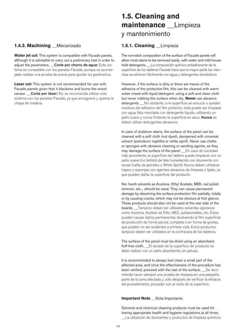
14
1.5. Cleaning and maintenance __Limpieza y mantenimiento
1.5.1. Cleaning __Limpieza
The non-stick composition of the surface of Facade panels will allow most stains to be removed easily, with water and mild house-hold detergents. __La composición química antiadherente de la superficie de los tableros Facade hace que la mayor parte las man-chas se eliminen fácilmente con agua y detergentes domésticos.
However, if the surface is dirty or there are traces of the adhesive of the protective film, this can be cleaned with warm water mixed with liquid detergent, using a soft and clean cloth but never rubbing the surface when dry. Never use abrasive detergents. __No obstante, si la superficie se ensucia o quedan residuos del adhesivo del film protector, ésta puede ser limpiada con agua tibia mezclada con detergente líquido, utilizando un paño suave y nunca frotando la superficie en seco. Nunca se deben utilizar detergentes abrasivos.
In case of stubborn stains, the surface of the panel can be cleaned with a soft cloth (not dyed), dampened with universal solvent (petroleum naphtha or white spirit). Never use cloths or sponges with abrasive cleaning or sanding agents, as they may damage the surface of the panel. __En caso de suciedad más persistente, la superficie del tablero puede limpiarse con un paño suave (no teñido) de tela humedecido con disolvente uni-versal (nafta de petróleo o White Spirit). Nunca deben utilizarse trapos o esponjas con agentes abrasivos de limpieza o lijado, ya que pueden dañar la superficie del producto.
Nor harsh solvents as Acetone, Ethyl Acetate, MEK, nail polish remover, etc... should be used. They can cause permanent damage by dissolving the surface protection film partially, totally or by causing cracks, which may not be obvious at first glance. These products should also not be used at the rear side of the boards. __Tampoco deben ser utilizados solventes agresivos como Acetona, Acetato de Etilo, MEC, quitaesmaltes, etc. Éstos pueden causar daños permanentes disolviendo el film superficial de protección de forma parcial, completa o en forma de grietas, que pueden no ser evidentes a primera vista. Estos productos tampoco deben ser utilizados en la contracara de los tableros.
The surface of the panel must be dried using an absorbent, fluff-free cloth. __El secado de la superficie del producto se debe realizar con un paño absorbente, sin pelusa.
It is recommended to always test clean a small part of the affected area, and once the effectiveness of the procedure has been verified, proceed with the rest of the surface. __Se reco-mienda hacer siempre una prueba de limpieza en una pequeña parte de la zona afectada y, sólo después de verificar la eficacia del procedimiento, proceder con el resto de la superficie.
Important Note __Nota Importante
Solvents and chemical cleaning products must be used fol-lowing appropriate health and hygiene regulations at all times. __La utilización de disolventes y productos de limpieza químicos
1.4.3. Machining __Mecanizado
Water jet cut: This system is compatible with Facade panels, although it is advisable to carry out a preliminary test in order to adjust the parameters. __Corte por chorro de agua: Este sis-tema es compatible con los paneles Facade, aunque es aconse-jable realizar una prueba de previa para ajustar los parámetros.
Laser cut: This system is not recommended for use with Facade panels given that it blackens and burns the wood veneer. __Corte por láser: No se recomienda utilizar este sistema con los paneles Facade, ya que ennegrece y quema la chapa de madera.

15
1.6. Information for removal __Información para la desinstalación
The main components for the Facade panels installation (aluminium, steel, timber and/or plastic) are easily separated for recycling. __Los principales componentes para la instalación de los paneles Facade (aluminio, acero, madera y/o plástico) son fácilmente separables y reciclables.
1.6.1. Waste management information __Información a los gestores de residuos
The specifications that rule the production and management of waste generated in construction and demolition must be fulfilled, as well as any current local regulation. __Se seguirán las especificaciones que regulan la producción y gestión de los residuos de construcción y demolición, así como las reglamenta-ciones locales que sean de aplicación.
The re-use of the Facade panels in other applications with differ-ent requirements is encouraged. __Se favorecerá la reutilización del panel Facade en otras aplicaciones con diferentes requisitos.
It is possible the assessment of the waste by industrial incinera-tion. __También es posible su valorización en incineradoras de uso industrial.
debe realizarse respetando siempre las correspondientes reglas de seguridad e higiene.
Cleaning graffiti __Limpieza de grafitis
The specially treated non-stick surface of Facade will prevent aerosol paints from permanently adhering to the surface of the panel.. However, removal may require products specifically designed for removing this type of paint. A final cleaning with soapy water and a full rinse with clean water are recommended. __La superficie químicamente antiadherente de Facade impide que las pinturas en aerosol queden fijadas permanentemente. No obstante, su limpieza puede requerir de productos específi-cos para este tipo de pinturas. Se recomienda una limpieza final con agua jabonosa y un aclarado final con agua limpia.
We have specific Resistance to Graffiti tests available for stains made with the following materials: __Le informamos que disponemos de ensayos específicos de Resistencia a la pintura grafiti para marcas realizadas con los siguientes materiales:
• Solvent-based: permanent blue marker and red spray paint. __Rotulador azul permanente y spray rojo, con base solvente.
• Black wax. __Cera negra.• Water-based black marker. __Rotulador negro en base agua.
Never use abrasive cleaning powders or pastes, which will scratch the surface. __Nunca utilizar polvos o pastas de limpieza.
If you would like to see the results of these tests, please request them from the Parklex sales network. __Si desea los resultados de estos ensayos, solicítelos a la red comercial de Parklex.
1.5.2. Maintenance __Mantenimiento
Simple cleaning of Facade panels is the only maintenance needed. The surface does not require any specific preventative treatment designed for wood. __La limpieza de los tableros Facade es el único mantenimiento necesario. La superficie no necesita ningún otro tratamiento preventivo para la madera.
1.5.3. Repair __Reparación
There is currently no prescribed method for repairing Facade panels. In case of severe damage, affected panels must be replaced with new. __No se ha prescrito ningún método de re-paración de los paneles Facade. Los paneles dañados deberán ser reemplazados por otros nuevos.


2. General Instructions __Instrucciones Generales
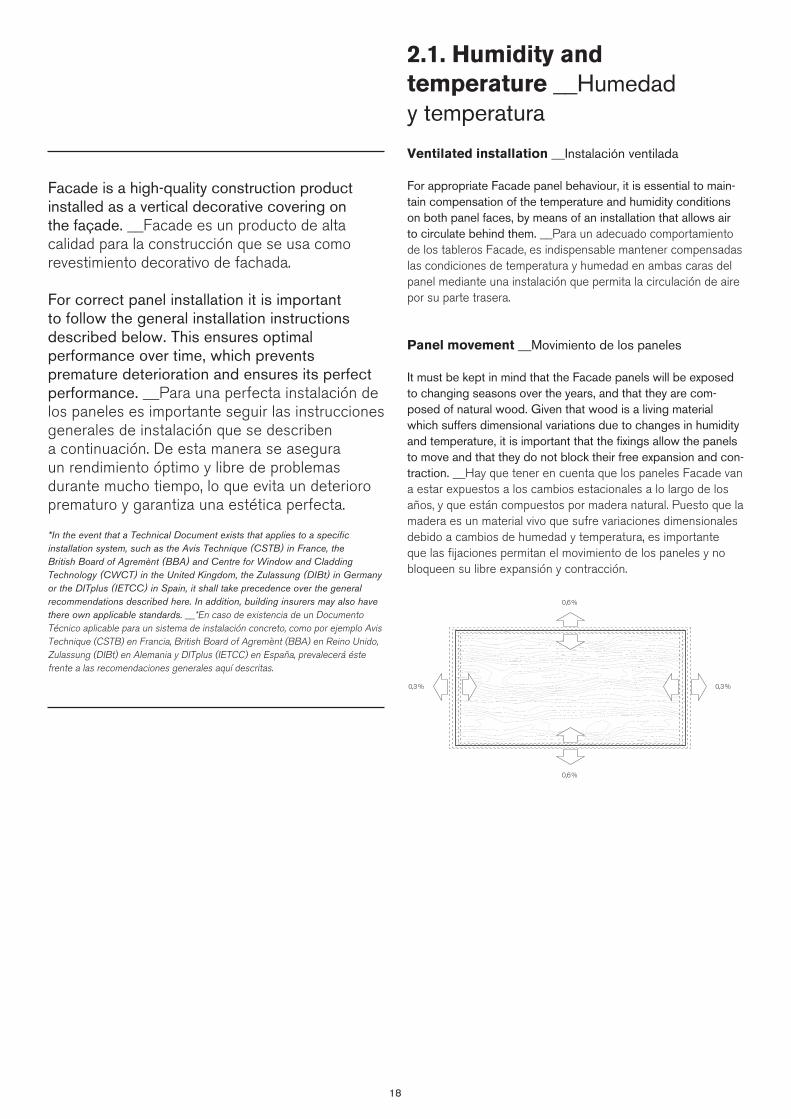
18
2.1. Humidity and temperature __Humedad y temperatura
Ventilated installation __Instalación ventilada
For appropriate Facade panel behaviour, it is essential to main-tain compensation of the temperature and humidity conditions on both panel faces, by means of an installation that allows air to circulate behind them. __Para un adecuado comportamiento de los tableros Facade, es indispensable mantener compensadas las condiciones de temperatura y humedad en ambas caras del panel mediante una instalación que permita la circulación de aire por su parte trasera.
Panel movement __Movimiento de los paneles
It must be kept in mind that the Facade panels will be exposed to changing seasons over the years, and that they are com-posed of natural wood. Given that wood is a living material which suffers dimensional variations due to changes in humidity and temperature, it is important that the fixings allow the panels to move and that they do not block their free expansion and con-traction. __Hay que tener en cuenta que los paneles Facade van a estar expuestos a los cambios estacionales a lo largo de los años, y que están compuestos por madera natural. Puesto que la madera es un material vivo que sufre variaciones dimensionales debido a cambios de humedad y temperatura, es importante que las fijaciones permitan el movimiento de los paneles y no bloqueen su libre expansión y contracción.
Facade is a high-quality construction product installed as a vertical decorative covering on the façade. __Facade es un producto de alta calidad para la construcción que se usa como revestimiento decorativo de fachada.
For correct panel installation it is important to follow the general installation instructions described below. This ensures optimal performance over time, which prevents premature deterioration and ensures its perfect performance. __Para una perfecta instalación de los paneles es importante seguir las instrucciones generales de instalación que se describen a continuación. De esta manera se asegura un rendimiento óptimo y libre de problemas durante mucho tiempo, lo que evita un deterioro prematuro y garantiza una estética perfecta.
*In the event that a Technical Document exists that applies to a specific installation system, such as the Avis Technique (CSTB) in France, the British Board of Agremènt (BBA) and Centre for Window and Cladding Technology (CWCT) in the United Kingdom, the Zulassung (DIBt) in Germany or the DITplus (IETCC) in Spain, it shall take precedence over the general recommendations described here. In addition, building insurers may also have there own applicable standards. __*En caso de existencia de un Documento Técnico aplicable para un sistema de instalación concreto, como por ejemplo Avis Technique (CSTB) en Francia, British Board of Agremènt (BBA) en Reino Unido, Zulassung (DIBt) en Alemania y DITplus (IETCC) en España, prevalecerá éste frente a las recomendaciones generales aquí descritas.
0,6%
0,6%
0,3% 0,3%
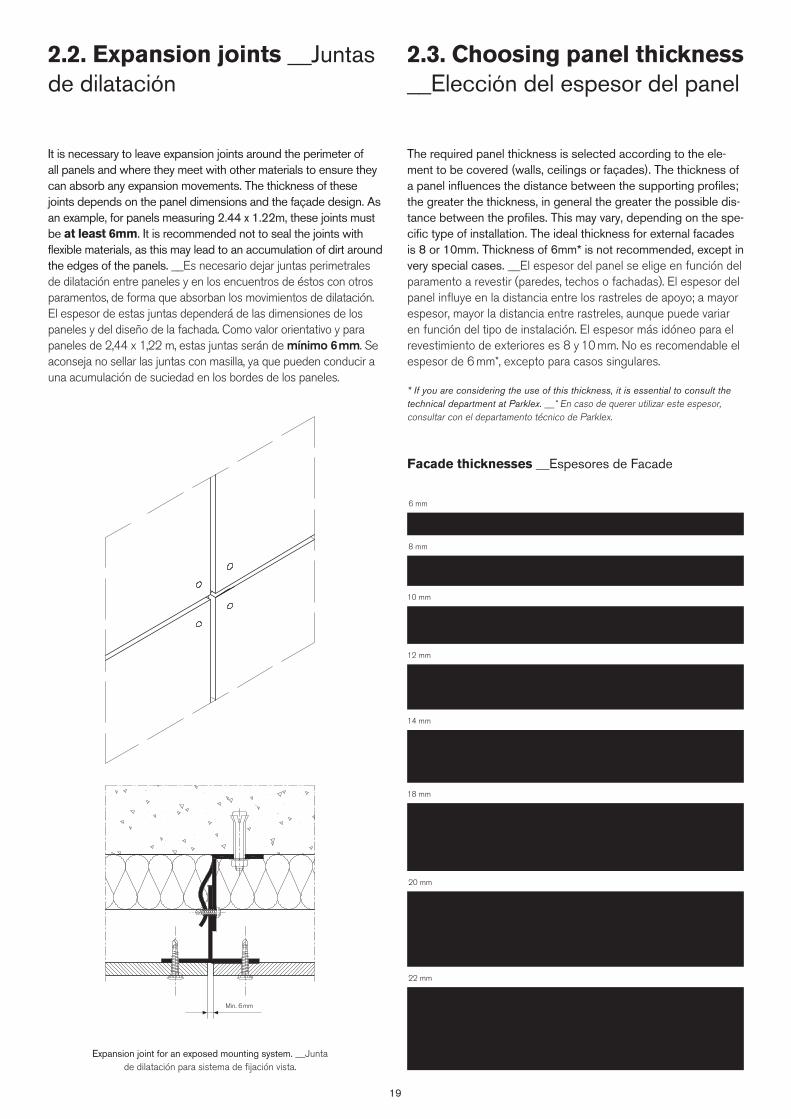
19
2.3. Choosing panel thickness __Elección del espesor del panel
The required panel thickness is selected according to the ele-ment to be covered (walls, ceilings or façades). The thickness of a panel influences the distance between the supporting profiles; the greater the thickness, in general the greater the possible dis-tance between the profiles. This may vary, depending on the spe-cific type of installation. The ideal thickness for external facades is 8 or 10mm. Thickness of 6mm* is not recommended, except in very special cases. __El espesor del panel se elige en función del paramento a revestir (paredes, techos o fachadas). El espesor del panel influye en la distancia entre los rastreles de apoyo; a mayor espesor, mayor la distancia entre rastreles, aunque puede variar en función del tipo de instalación. El espesor más idóneo para el revestimiento de exteriores es 8 y 10 mm. No es recomendable el espesor de 6 mm*, excepto para casos singulares.
* If you are considering the use of this thickness, it is essential to consult the technical department at Parklex. __* En caso de querer utilizar este espesor, consultar con el departamento técnico de Parklex.
Facade thicknesses __Espesores de Facade
6 mm
8 mm
10 mm
12 mm
14 mm
18 mm
20 mm
22 mm
2.2. Expansion joints __Juntas de dilatación
It is necessary to leave expansion joints around the perimeter of all panels and where they meet with other materials to ensure they can absorb any expansion movements. The thickness of these joints depends on the panel dimensions and the façade design. As an example, for panels measuring 2.44 x 1.22m, these joints must be at least 6mm. It is recommended not to seal the joints with flexible materials, as this may lead to an accumulation of dirt around the edges of the panels. __Es necesario dejar juntas perimetrales de dilatación entre paneles y en los encuentros de éstos con otros paramentos, de forma que absorban los movimientos de dilatación. El espesor de estas juntas dependerá de las dimensiones de los paneles y del diseño de la fachada. Como valor orientativo y para paneles de 2,44 x 1,22 m, estas juntas serán de mínimo 6 mm. Se aconseja no sellar las juntas con masilla, ya que pueden conducir a una acumulación de suciedad en los bordes de los paneles.
Expansion joint for an exposed mounting system. __Junta de dilatación para sistema de fijación vista.
Min. 6mm
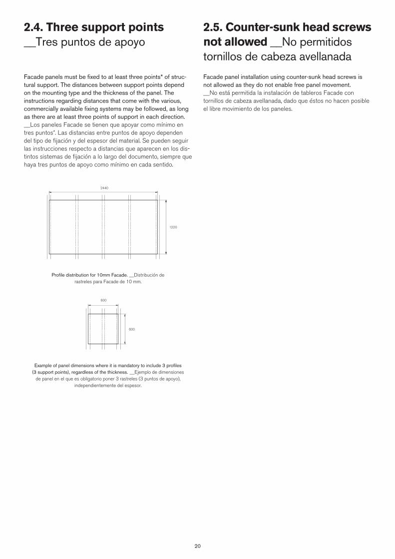
20
2.5. Counter-sunk head screws not allowed __No permitidos tornillos de cabeza avellanada
Facade panel installation using counter-sunk head screws is not allowed as they do not enable free panel movement. __No está permitida la instalación de tableros Facade con tornillos de cabeza avellanada, dado que éstos no hacen posible el libre movimiento de los paneles.
2.4. Three support points __Tres puntos de apoyo
Profile distribution for 10mm Facade. __Distribución de rastreles para Facade de 10 mm.
Example of panel dimensions where it is mandatory to include 3 profiles (3 support points), regardless of the thickness. __Ejemplo de dimensiones
de panel en el que es obligatorio poner 3 rastreles (3 puntos de apoyo), independientemente del espesor.
Facade panels must be fixed to at least three points* of struc-tural support. The distances between support points depend on the mounting type and the thickness of the panel. The instructions regarding distances that come with the various, commercially available fixing systems may be followed, as long as there are at least three points of support in each direction. __Los paneles Facade se tienen que apoyar como mínimo en tres puntos*. Las distancias entre puntos de apoyo dependen del tipo de fijación y del espesor del material. Se pueden seguir las instrucciones respecto a distancias que aparecen en los dis-tintos sistemas de fijación a lo largo del documento, siempre que haya tres puntos de apoyo como mínimo en cada sentido.
2440
1220
600
600


3. Installation system on ventilated façade __Sistema de instalación en fachada ventilada
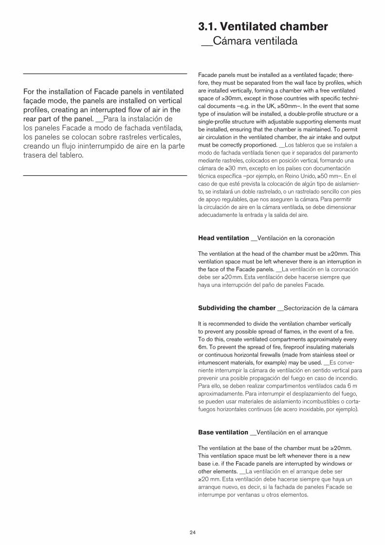
24
3.1. Ventilated chamber __Cámara ventilada
Facade panels must be installed as a ventilated façade; there-fore, they must be separated from the wall face by profiles, which are installed vertically, forming a chamber with a free ventilated space of ≥30mm, except in those countries with specific techni-cal documents –e.g. in the UK, ≥50mm–. In the event that some type of insulation will be installed, a double-profile structure or a single-profile structure with adjustable supporting elements must be installed, ensuring that the chamber is maintained. To permit air circulation in the ventilated chamber, the air intake and output must be correctly proportioned. __Los tableros que se instalen a modo de fachada ventilada tienen que ir separados del paramento mediante rastreles, colocados en posición vertical, formando una cámara de ≥30 mm, excepto en los países con documentación técnica específica –por ejemplo, en Reino Unido, ≥50 mm–. En el caso de que esté prevista la colocación de algún tipo de aislamien-to, se instalará un doble rastrelado, o un rastrelado sencillo con pies de apoyo regulables, que nos aseguren la cámara. Para permitir la circulación de aire en la cámara ventilada, se debe dimensionar adecuadamente la entrada y la salida del aire.
Head ventilation __Ventilación en la coronación
The ventilation at the head of the chamber must be ≥20mm. This ventilation space must be left whenever there is an interruption in the face of the Facade panels. __La ventilación en la coronación debe ser ≥20 mm. Esta ventilación debe hacerse siempre que haya una interrupción del paño de paneles Facade.
Subdividing the chamber __Sectorización de la cámara
It is recommended to divide the ventilation chamber vertically to prevent any possible spread of flames, in the event of a fire. To do this, create ventilated compartments approximately every 6m. To prevent the spread of fire, fireproof insulating materials or continuous horizontal firewalls (made from stainless steel or intumescent materials, for example) may be used. __Es conve-niente interrumpir la cámara de ventilación en sentido vertical para prevenir una posible propagación del fuego en caso de incendio. Para ello, se deben realizar compartimentos ventilados cada 6 m aproximadamente. Para interrumpir el desplazamiento del fuego, se pueden usar materiales de aislamiento incombustibles o corta-fuegos horizontales continuos (de acero inoxidable, por ejemplo).
Base ventilation __Ventilación en el arranque
The ventilation at the base of the chamber must be ≥20mm. This ventilation space must be left whenever there is a new base i.e. if the Facade panels are interrupted by windows or other elements. __La ventilación en el arranque debe ser ≥20 mm. Esta ventilación debe hacerse siempre que haya un arranque nuevo, es decir, si la fachada de paneles Facade se interrumpe por ventanas u otros elementos.
For the installation of Facade panels in ventilated façade mode, the panels are installed on vertical profiles, creating an interrupted flow of air in the rear part of the panel. __Para la instalación de los paneles Facade a modo de fachada ventilada, los paneles se colocan sobre rastreles verticales, creando un flujo ininterrumpido de aire en la parte trasera del tablero.

2525
Permeability
Permeabilidad
Moving air diffuses water vapour
from the inside out and facilitates the
‘breathing’ of the façade, preventing
condensation from forming behind the
panels. __El aire en movimiento difun-
de el vapor de agua desde el interior al
exterior y facilita la transpiración de la
fachada, lo que evita las condensacio-
nes detrás de los paneles.
Water protection
Protección frente al agua
Moving air provides protection from
the elements, because it assists in
preventing rain water from infiltrating
the building structure. __El aire en
movimiento proporciona una mayor
protección a la intemperie, porque
impide la infiltración de agua de lluvia
en la estructura del edificio.
Thermal insulation
Aislamiento térmico
The load-bearing structure is insulated
from the exterior structure, eliminat-
ing thermal bridges. In this manner,
temperature fluctuations are reduced
in the interior, leading to energy sav-
ings. __Aísla la estructura portante de
la estructura exterior, eliminando los
puentes térmicos. De esta forma se
reducen las fluctuaciones de tempera-
tura en el cerramiento interior, con el
consiguiente ahorro energético.
Solar protection Protección solar
Thermal comfort is improved inside
the building by preventing overheat-
ing in the summer, as it facilitates
‘breathing’ of the façade. This assists
by reducing the amount of thermal
energy that reaches the inside of the
building. The internal structure is pro-
tected from direct radiation and from
the elements. __Mejora el confort
térmico interior del edifico, evitando el
sobrecalentamiento en verano, porque
facilita la transpiración de la fachada
y se reduce la cantidad de energía
térmica que llega al interior del edificio.
Protege la estructura interna de las
radiaciones directas y de las inclemen-
cias meteorológicas.
Acoustic protection
Protección acústica
Since this is a compound system with
several layers, noise absorption is cre-
ated. __Al ser un sistema compuesto
con varios estratos, genera una mayor
absorción del ruido.
A. Facade panel __Panel FacadeB. Metal batten __Rastrel metálico vertical
C. Fixing bracket __Pie regulador de aplomadoD. Insulation __Aislante
E. Screw __TornilloL. Metal plate __Chapa metálicaM. Perforated profile __Rejilla
a ≥ 30mm (Except in those countries with specific documentation) a ≥ 30 mm (Excepto en los países con documentación técnica específica)
1
2
3
L
B
E
A
L
C
E
C
A
B
E
A
D
D
B
C
D
M
E
a
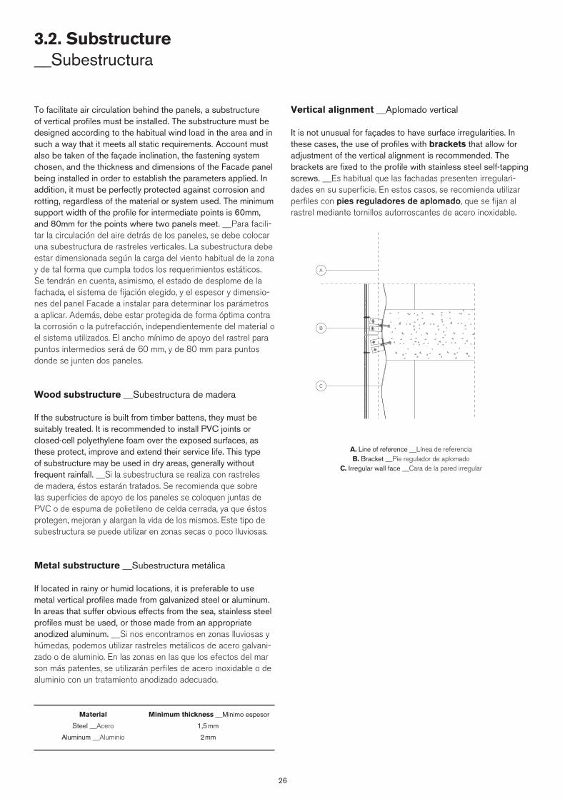
26
To facilitate air circulation behind the panels, a substructure of vertical profiles must be installed. The substructure must be designed according to the habitual wind load in the area and in such a way that it meets all static requirements. Account must also be taken of the façade inclination, the fastening system chosen, and the thickness and dimensions of the Facade panel being installed in order to establish the parameters applied. In addition, it must be perfectly protected against corrosion and rotting, regardless of the material or system used. The minimum support width of the profile for intermediate points is 60mm, and 80mm for the points where two panels meet. __Para facili-tar la circulación del aire detrás de los paneles, se debe colocar una subestructura de rastreles verticales. La subestructura debe estar dimensionada según la carga del viento habitual de la zona y de tal forma que cumpla todos los requerimientos estáticos. Se tendrán en cuenta, asimismo, el estado de desplome de la fachada, el sistema de fijación elegido, y el espesor y dimensio-nes del panel Facade a instalar para determinar los parámetros a aplicar. Además, debe estar protegida de forma óptima contra la corrosión o la putrefacción, independientemente del material o el sistema utilizados. El ancho mínimo de apoyo del rastrel para puntos intermedios será de 60 mm, y de 80 mm para puntos donde se junten dos paneles.
Wood substructure __Subestructura de madera
If the substructure is built from timber battens, they must be suitably treated. It is recommended to install PVC joints or closed-cell polyethylene foam over the exposed surfaces, as these protect, improve and extend their service life. This type of substructure may be used in dry areas, generally without frequent rainfall. __Si la subestructura se realiza con rastreles de madera, éstos estarán tratados. Se recomienda que sobre las superficies de apoyo de los paneles se coloquen juntas de PVC o de espuma de polietileno de celda cerrada, ya que éstos protegen, mejoran y alargan la vida de los mismos. Este tipo de subestructura se puede utilizar en zonas secas o poco lluviosas.
Metal substructure __Subestructura metálica
If located in rainy or humid locations, it is preferable to use metal vertical profiles made from galvanized steel or aluminum. In areas that suffer obvious effects from the sea, stainless steel profiles must be used, or those made from an appropriate anodized aluminum. __Si nos encontramos en zonas lluviosas y húmedas, podemos utilizar rastreles metálicos de acero galvani-zado o de aluminio. En las zonas en las que los efectos del mar son más patentes, se utilizarán perfiles de acero inoxidable o de aluminio con un tratamiento anodizado adecuado.
Material Minimum thickness __Mínimo espesor
Steel __Acero 1,5 mm
Aluminum __Aluminio 2 mm
Vertical alignment __Aplomado vertical
It is not unusual for façades to have surface irregularities. In these cases, the use of profiles with brackets that allow for adjustment of the vertical alignment is recommended. The brackets are fixed to the profile with stainless steel self-tapping screws. __Es habitual que las fachadas presenten irregulari-dades en su superficie. En estos casos, se recomienda utilizar perfiles con pies reguladores de aplomado, que se fijan al rastrel mediante tornillos autorroscantes de acero inoxidable.
3.2. Substructure __Subestructura
A. Line of reference __Línea de referenciaB. Bracket __Pie regulador de aplomado
C. Irregular wall face __Cara de la pared irregular
C
B
A
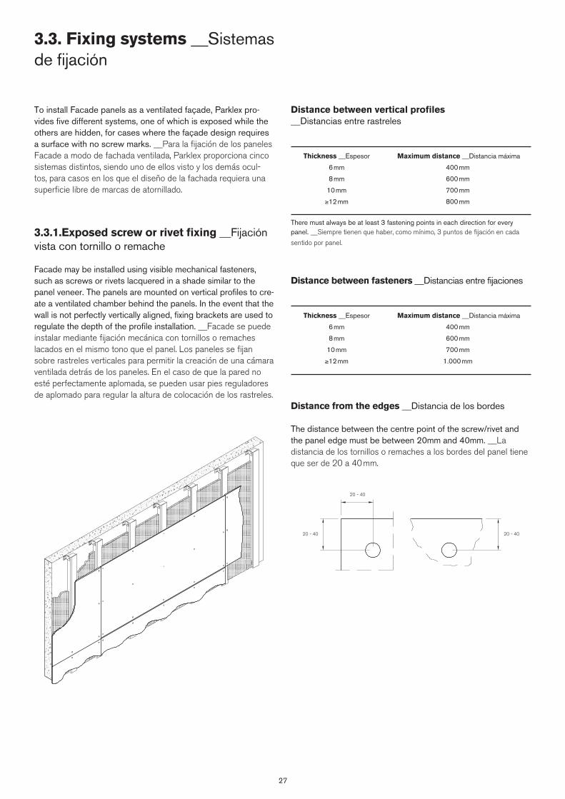
27
To install Facade panels as a ventilated façade, Parklex pro-vides five different systems, one of which is exposed while the others are hidden, for cases where the façade design requires a surface with no screw marks. __Para la fijación de los paneles Facade a modo de fachada ventilada, Parklex proporciona cinco sistemas distintos, siendo uno de ellos visto y los demás ocul-tos, para casos en los que el diseño de la fachada requiera una superficie libre de marcas de atornillado.
3.3.1.Exposed screw or rivet fixing __Fijación vista con tornillo o remache
Facade may be installed using visible mechanical fasteners, such as screws or rivets lacquered in a shade similar to the panel veneer. The panels are mounted on vertical profiles to cre-ate a ventilated chamber behind the panels. In the event that the wall is not perfectly vertically aligned, fixing brackets are used to regulate the depth of the profile installation. __Facade se puede instalar mediante fijación mecánica con tornillos o remaches lacados en el mismo tono que el panel. Los paneles se fijan sobre rastreles verticales para permitir la creación de una cámara ventilada detrás de los paneles. En el caso de que la pared no esté perfectamente aplomada, se pueden usar pies reguladores de aplomado para regular la altura de colocación de los rastreles.
Distance between vertical profiles __Distancias entre rastreles
Thickness __Espesor Maximum distance __Distancia máxima
6 mm 400 mm
8 mm 600 mm
10 mm 700 mm
≥12 mm 800 mm
There must always be at least 3 fastening points in each direction for every panel. __Siempre tienen que haber, como mínimo, 3 puntos de fijación en cada
sentido por panel.
Distance between fasteners __Distancias entre fijaciones
Thickness __Espesor Maximum distance __Distancia máxima
6 mm 400 mm
8 mm 600 mm
10 mm 700 mm
≥12 mm 1.000 mm
Distance from the edges __Distancia de los bordes
The distance between the centre point of the screw/rivet and the panel edge must be between 20mm and 40mm. __La distancia de los tornillos o remaches a los bordes del panel tiene que ser de 20 a 40 mm.
3.3. Fixing systems __Sistemas de fijación
20 - 40
20 - 40 20 - 40

Centering the screw / rivet __Centrado del tornillo / remache
The screw / rivet must be centered in the holes to permit di-mensional variations. __El tornillo / remache debe estar centrado en las perforaciones para permitir las variaciones dimensionales.
Panel Fixings __Elementos de fijación
Facade may be installed using visible mechanical fasteners, such as screws or rivets lacquered in a shade similar to the panel veneer, offered by Parklex. __Parklex ofrece tornillos y remaches lacados del mismo color de los acabados de los paneles para la instalación de Facade.
- TWD-S-D12: Screw for fixing to timber battens. __Tornillo para fijación en rastrel de madera.
- SX3-L12: Screw for fixing to metal profiles. A special screwdriver tip supplied by Parklex must be used to insert this type of screw. Max. drilling capacity: 2,5mm. __Tornillo para fijación en rastrel metálico. Es necesario usar una punta de atornillador especial para fijar este tornillo. Capacidad máxima de taladrado: 2,5 mm.
- AP16: Rivet for fixing to aluminum profiles. Assembly capac-ity: 16mm: 8-12 mm / 21mm: 12,5-16mm __Remache para la fijación en rastrel de aluminio. Capacidad de ensamblaje: 16 mm: 8-12 mm / 21 mm: 12,5-16 mm.
28
Fixed point and floating point __Punto fijo y punto flotante
All mounting points for Facade panels must be floating (with a diameter of at least 3mm larger than that of the screw or rivet; see the next chapter.), except for one, which must be fixed. This is the point around which the panel will expand and contract. This fixed point must be as close as possible to the center of the panel. __Todos los puntos de fijación de los paneles de fachada Facade tienen que ser flotantes (de diámetro superior al del tornillo o remache, ver capítulo siguiente), excepto uno de ellos, que tiene que ser fijo. Este punto fijo deberá estar lo más cerca posible del centro del panel.
Fixed Points __Puntos fijos Floating Points __Puntos flotantes
D = 12 L = 38 mm
D = 4.8 mm
D = 12 L = 32 mm
D = 16
OK NO
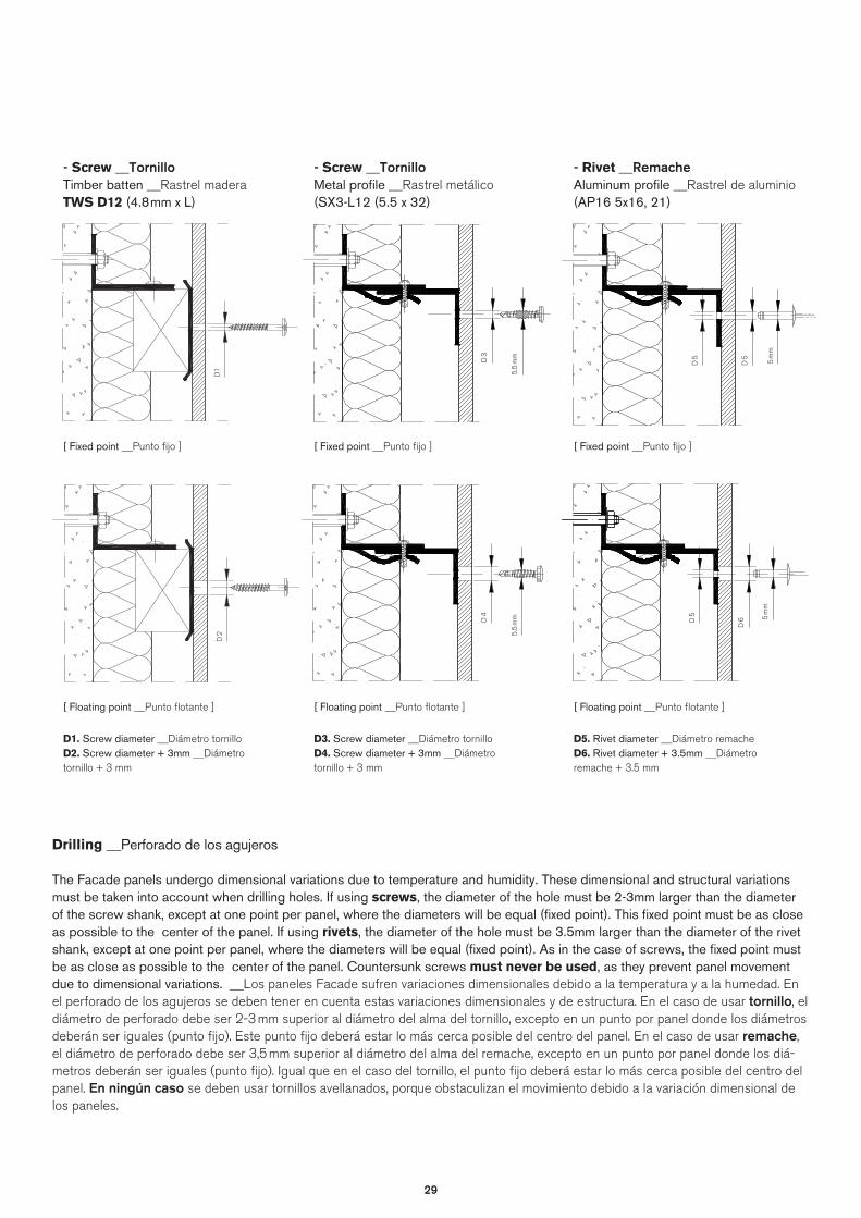
2929
- Rivet __RemacheAluminum profile __Rastrel de aluminio(AP16 5x16, 21)
[ Fixed point __Punto fijo ]
[ Floating point __Punto flotante ]
D5. Rivet diameter __Diámetro remacheD6. Rivet diameter + 3.5mm __Diámetro remache + 3.5 mm
Drilling __Perforado de los agujeros
The Facade panels undergo dimensional variations due to temperature and humidity. These dimensional and structural variations must be taken into account when drilling holes. If using screws, the diameter of the hole must be 2-3mm larger than the diameter of the screw shank, except at one point per panel, where the diameters will be equal (fixed point). This fixed point must be as close as possible to the center of the panel. If using rivets, the diameter of the hole must be 3.5mm larger than the diameter of the rivet shank, except at one point per panel, where the diameters will be equal (fixed point). As in the case of screws, the fixed point must be as close as possible to the center of the panel. Countersunk screws must never be used, as they prevent panel movement due to dimensional variations. __Los paneles Facade sufren variaciones dimensionales debido a la temperatura y a la humedad. En el perforado de los agujeros se deben tener en cuenta estas variaciones dimensionales y de estructura. En el caso de usar tornillo, el diámetro de perforado debe ser 2-3 mm superior al diámetro del alma del tornillo, excepto en un punto por panel donde los diámetros deberán ser iguales (punto fijo). Este punto fijo deberá estar lo más cerca posible del centro del panel. En el caso de usar remache, el diámetro de perforado debe ser 3,5 mm superior al diámetro del alma del remache, excepto en un punto por panel donde los diá-metros deberán ser iguales (punto fijo). Igual que en el caso del tornillo, el punto fijo deberá estar lo más cerca posible del centro del panel. En ningún caso se deben usar tornillos avellanados, porque obstaculizan el movimiento debido a la variación dimensional de los paneles.
- Screw __TornilloTimber batten __Rastrel maderaTWS D12 (4.8mm x L)
[ Fixed point __Punto fijo ]
[ Floating point __Punto flotante ]
D1. Screw diameter __Diámetro tornilloD2. Screw diameter + 3mm __Diámetro tornillo + 3 mm
- Screw __TornilloMetal profile __Rastrel metálico(SX3-L12 (5.5 x 32)
[ Fixed point __Punto fijo ]
[ Floating point __Punto flotante ]
D3. Screw diameter __Diámetro tornilloD4. Screw diameter + 3mm __Diámetro tornillo + 3 mm
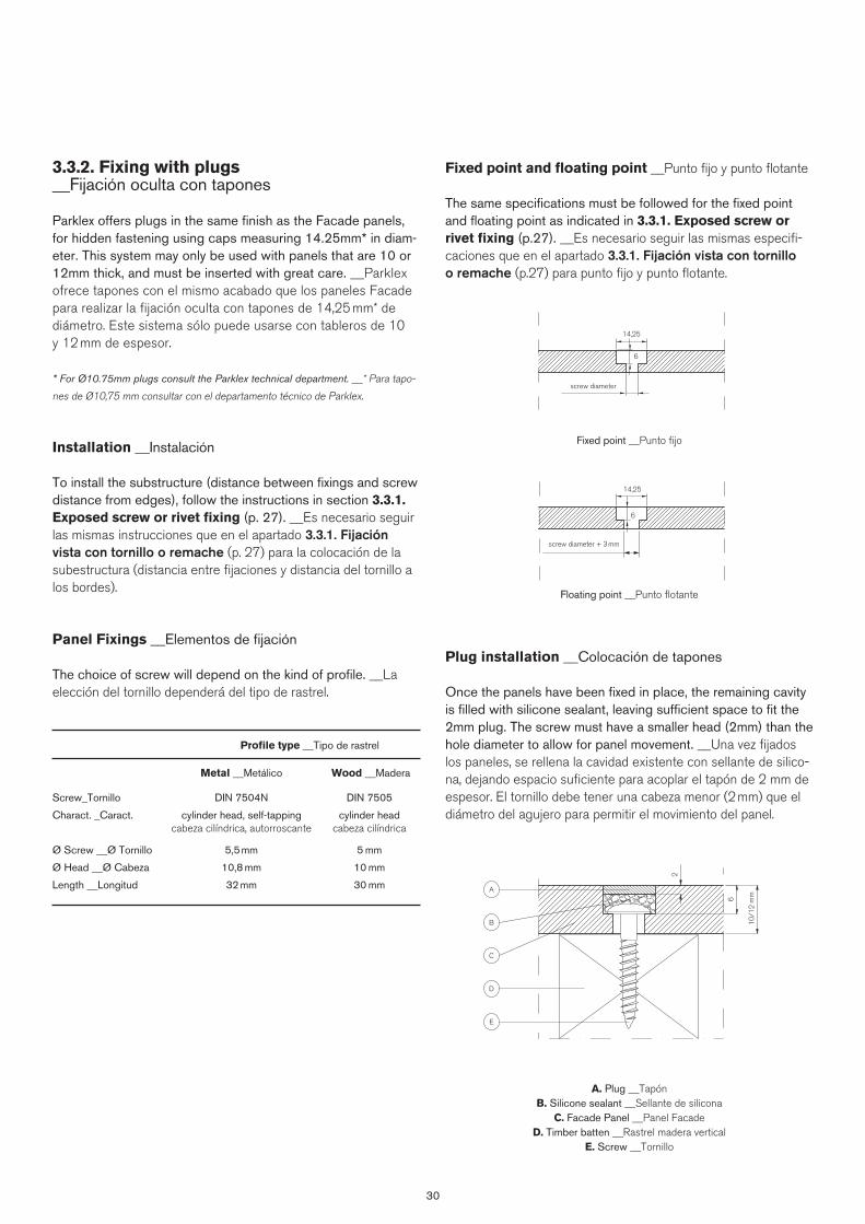
30
3.3.2. Fixing with plugs __Fijación oculta con tapones
Parklex offers plugs in the same finish as the Facade panels, for hidden fastening using caps measuring 14.25mm* in diam-eter. This system may only be used with panels that are 10 or 12mm thick, and must be inserted with great care. __Parklex ofrece tapones con el mismo acabado que los paneles Facade para realizar la fijación oculta con tapones de 14,25 mm* de diámetro. Este sistema sólo puede usarse con tableros de 10 y 12 mm de espesor.
* For Ø10.75mm plugs consult the Parklex technical department. __* Para tapo-
nes de Ø10,75 mm consultar con el departamento técnico de Parklex.
Installation __Instalación
To install the substructure (distance between fixings and screw distance from edges), follow the instructions in section 3.3.1. Exposed screw or rivet fixing (p. 27). __Es necesario seguir las mismas instrucciones que en el apartado 3.3.1. Fijación vista con tornillo o remache (p. 27) para la colocación de la subestructura (distancia entre fijaciones y distancia del tornillo a los bordes).
Panel Fixings __Elementos de fijación The choice of screw will depend on the kind of profile. __La elección del tornillo dependerá del tipo de rastrel.
Profile type __Tipo de rastrel
Metal __Metálico Wood __Madera
Screw_Tornillo DIN 7504N DIN 7505
Charact. _Caract. cylinder head, self-tapping cylinder head cabeza cilíndrica, autorroscante cabeza cilíndrica
Ø Screw __Ø Tornillo 5,5mm 5 mm
Ø Head __Ø Cabeza 10,8 mm 10 mm
Length __Longitud 32 mm 30 mm
Fixed point and floating point __Punto fijo y punto flotante
The same specifications must be followed for the fixed point and floating point as indicated in 3.3.1. Exposed screw or rivet fixing (p.27). __Es necesario seguir las mismas especifi-caciones que en el apartado 3.3.1. Fijación vista con tornillo o remache (p.27) para punto fijo y punto flotante.
Plug installation __Colocación de tapones
Once the panels have been fixed in place, the remaining cavity is filled with silicone sealant, leaving sufficient space to fit the 2mm plug. The screw must have a smaller head (2mm) than the hole diameter to allow for panel movement. __Una vez fijados los paneles, se rellena la cavidad existente con sellante de silico-na, dejando espacio suficiente para acoplar el tapón de 2 mm de espesor. El tornillo debe tener una cabeza menor (2 mm) que el diámetro del agujero para permitir el movimiento del panel.
A. Plug __TapónB. Silicone sealant __Sellante de silicona
C. Facade Panel __Panel FacadeD. Timber batten __Rastrel madera vertical
E. Screw __Tornillo
Fixed point __Punto fijo
Floating point __Punto flotante
14,25
6
screw diameter
14,25
6
screw diameter + 3mm
E
D
C
B
A
2
6
10/1
2m
m
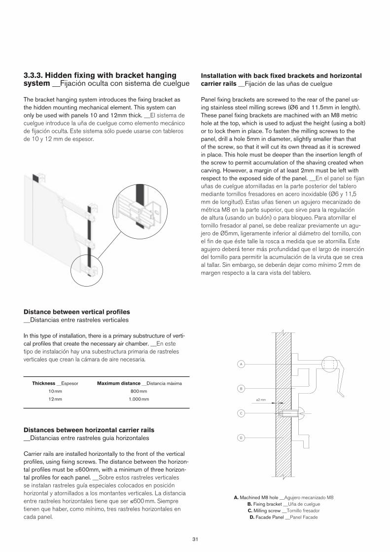
31
3.3.3. Hidden fixing with bracket hanging system __Fijación oculta con sistema de cuelgue
The bracket hanging system introduces the fixing bracket as the hidden mounting mechanical element. This system can only be used with panels 10 and 12mm thick. __El sistema de cuelgue introduce la uña de cuelgue como elemento mecánico de fijación oculta. Este sistema sólo puede usarse con tableros de 10 y 12 mm de espesor.
Distance between vertical profiles __Distancias entre rastreles verticales
In this type of installation, there is a primary substructure of verti-cal profiles that create the necessary air chamber. __En este tipo de instalación hay una subestructura primaria de rastreles verticales que crean la cámara de aire necesaria.
Thickness __Espesor Maximum distance __Distancia máxima
10 mm 800 mm
12 mm 1.000 mm
Distances between horizontal carrier rails __Distancias entre rastreles guía horizontales
Carrier rails are installed horizontally to the front of the vertical profiles, using fixing screws. The distance between the horizon-tal profiles must be ≤600mm, with a minimum of three horizon-tal profiles for each panel. __Sobre estos rastreles verticales se instalan rastreles guía especiales colocados en posición horizontal y atornillados a los montantes verticales. La distancia entre rastreles horizontales tiene que ser ≤600 mm. Siempre tienen que haber, como mínimo, tres rastreles horizontales en cada panel.
Installation with back fixed brackets and horizontal carrier rails __Fijación de las uñas de cuelgue
Panel fixing brackets are screwed to the rear of the panel us-ing stainless steel milling screws (Ø6 and 11.5mm in length). These panel fixing brackets are machined with an M8 metric hole at the top, which is used to adjust the height (using a bolt) or to lock them in place. To fasten the milling screws to the panel, drill a hole 5mm in diameter, slightly smaller than that of the screw, so that it will cut its own thread as it is screwed in place. This hole must be deeper than the insertion length of the screw to permit accumulation of the shaving created when carving. However, a margin of at least 2mm must be left with respect to the exposed side of the panel. __En el panel se fijan uñas de cuelgue atornilladas en la parte posterior del tablero mediante tornillos fresadores en acero inoxidable (Ø6 y 11,5 mm de longitud). Estas uñas tienen un agujero mecanizado de métrica M8 en la parte superior, que sirve para la regulación de altura (usando un bulón) o para bloqueo. Para atornillar el tornillo fresador al panel, se debe realizar previamente un agu-jero de Ø5mm, ligeramente inferior al diámetro del tornillo, con el fin de que éste talle la rosca a medida que se atornilla. Este agujero deberá tener más profundidad que el largo de inserción del tornillo para permitir la acumulación de la viruta que se crea al tallar. Sin embargo, se deberán dejar como mínimo 2 mm de margen respecto a la cara vista del tablero.
A. Machined M8 hole __Agujero mecanizado M8B. Fixing bracket __Uña de cuelgue C. Milling screw __Tornillo fresadorD. Facade Panel __Panel Facade
D
C
B
A
≥2 mm
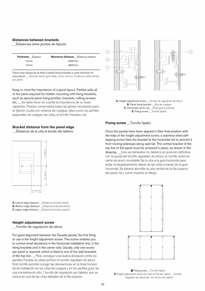
32
Fixing screw __Tornillo fijadorHeight adjustment screw (on one of the two sides) __Tornillo
regulador de altura (en uno de los dos lados)
Distances between brackets __Distancias entre puntos de fijación
Thickness __Espesor Maximum distance __Distancia máxima
10 mm ≤600 mm
12 mm ≤800 mm
There must always be at least 3 panel fixing brackets in each direction for every panel. __Siempre tienen que haber, como mínimo, 3 uñas en cada sentido por panel.
Keep in mind the importance of a good layout. Parklex sells all of the parts required for hidden mounting with fixing brackets, such as special panel fixing profiles, brackets, milling screws, etc. __Se debe tener en cuenta la importancia de un buen replanteo. Parklex comercializa todas las piezas necesarias para la fijación oculta con sistema de cuelgue, tales como los perfiles especiales de cuelgue, las uñas, el tornillo fresador, etc.
Bracket distance from the panel edge __Distancia de la uña al borde del tablero
Height adjustment screw __Tornillo de regulación de altura
For good alignment between the Facade panels, the first thing to use is the height adjustment screw. This screw enables you to correct small deviations in the horizontal installation line, in the fixing brackets and in the carrier rails. Usually, only one screw per panel is required, which is fixed to one of the side brackets of the top line. __Para conseguir una buena alineación entre los paneles Facade se utiliza primero el tornillo regulador de altura. Este tornillo permite corregir las desviaciones en la línea horizon-tal de instalación en las uñas de cuelgue y en los perfiles guía. Se usa normalmente sólo 1 tornillo de regulación por tablero, que se coloca en una de las uñas laterales de la fila superior.
Fixing screw __Tornillo fijador
Once the panels have been aligned in their final position with the help of the height adjustment screw, a stainless steel self-tapping screw fixes the bracket to the horizontal rail to prevent it from moving sideways along said rail. The central bracket of the top line of the panel must be screwed in place, as shown in the drawing. __Una vez alineados los tableros en posición definitiva con la ayuda del tornillo regulador de altura, un tornillo autorros-cante de acero inoxidable fija la uña a la guía horizontal para evitar el desplazamiento lateral de las uñas a través de la guía horizontal. Se deberá atornillar la uña central de la fila superior del panel, tal y como muestra el dibujo.
C =
58
mm
B =
45
mm
A = 24 mm
A. Lateral edge distance __Distancia al borde lateralB. Bottom edge distance __Distancia al borde inferiorC. Upper edge distance __Distancia al borde superior
A. Height adjustment screw __Tornillo de regulación de alturaB. Panel fixing bracket __Uña de cuelgue
C. Horizontal carrier rail __Perfil guía horizontalD. Fixing screw __Tornillo fijador
A
B
C
D
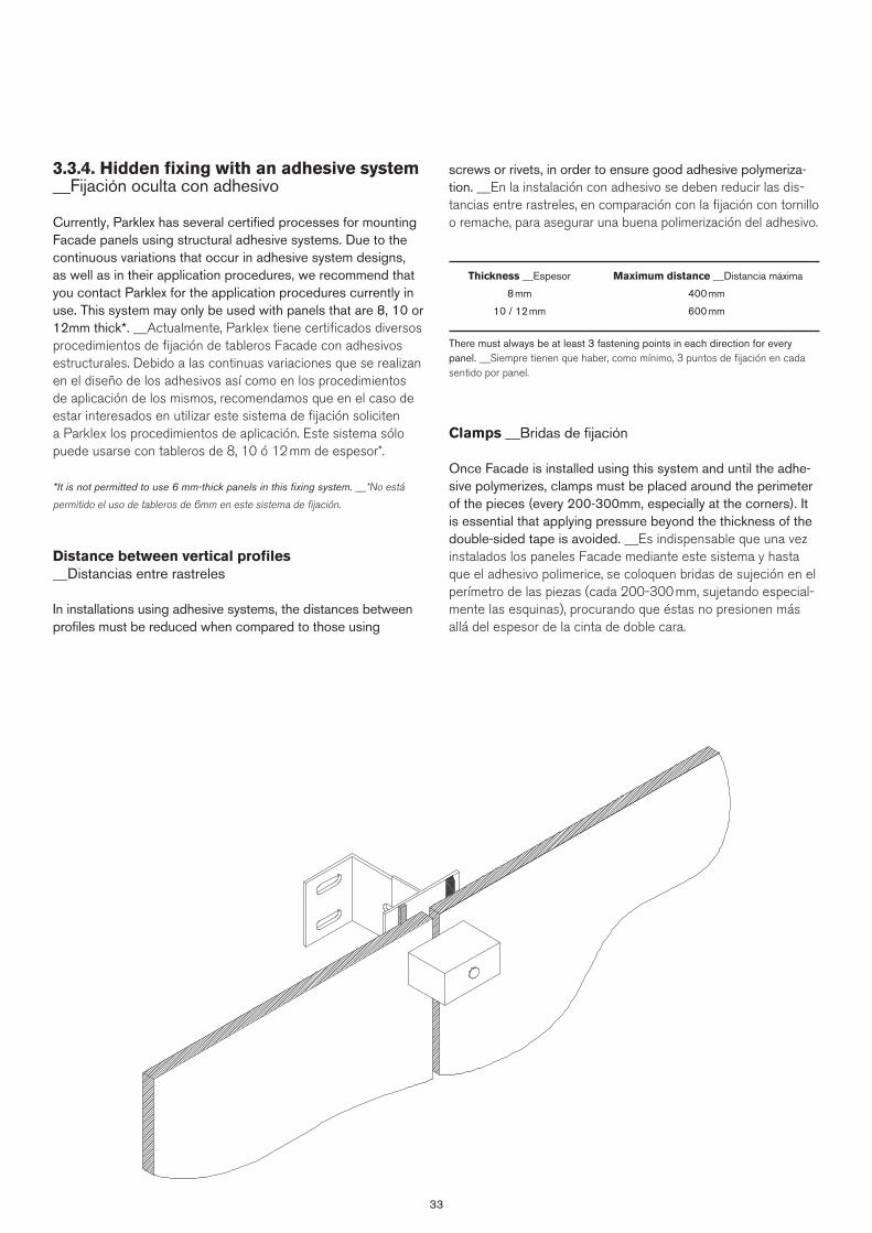
33
3.3.4. Hidden fixing with an adhesive system __Fijación oculta con adhesivo
Currently, Parklex has several certified processes for mounting Facade panels using structural adhesive systems. Due to the continuous variations that occur in adhesive system designs, as well as in their application procedures, we recommend that you contact Parklex for the application procedures currently in use. This system may only be used with panels that are 8, 10 or 12mm thick*. __Actualmente, Parklex tiene certificados diversos procedimientos de fijación de tableros Facade con adhesivos estructurales. Debido a las continuas variaciones que se realizan en el diseño de los adhesivos así como en los procedimientos de aplicación de los mismos, recomendamos que en el caso de estar interesados en utilizar este sistema de fijación soliciten a Parklex los procedimientos de aplicación. Este sistema sólo puede usarse con tableros de 8, 10 ó 12 mm de espesor*.
*It is not permitted to use 6 mm-thick panels in this fixing system. __*No está
permitido el uso de tableros de 6mm en este sistema de fijación.
Distance between vertical profiles __Distancias entre rastreles
In installations using adhesive systems, the distances between profiles must be reduced when compared to those using
screws or rivets, in order to ensure good adhesive polymeriza-tion. __En la instalación con adhesivo se deben reducir las dis-tancias entre rastreles, en comparación con la fijación con tornillo o remache, para asegurar una buena polimerización del adhesivo.
Thickness __Espesor Maximum distance __Distancia máxima
8 mm 400 mm
10 / 12 mm 600 mm
There must always be at least 3 fastening points in each direction for every panel. __Siempre tienen que haber, como mínimo, 3 puntos de fijación en cada sentido por panel.
Clamps __Bridas de fijación
Once Facade is installed using this system and until the adhe-sive polymerizes, clamps must be placed around the perimeter of the pieces (every 200-300mm, especially at the corners). It is essential that applying pressure beyond the thickness of the double-sided tape is avoided. __Es indispensable que una vez instalados los paneles Facade mediante este sistema y hasta que el adhesivo polimerice, se coloquen bridas de sujeción en el perímetro de las piezas (cada 200-300 mm, sujetando especial-mente las esquinas), procurando que éstas no presionen más allá del espesor de la cinta de doble cara.
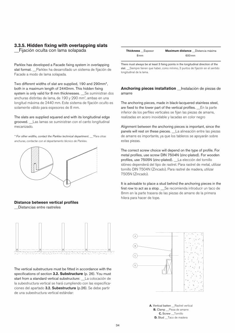
34
3.3.5. Hidden fixing with overlapping slats __Fijación oculta con lama solapada
Parklex has developed a Facade fixing system in overlapping slat format. __Parklex ha desarrollado un sistema de fijación de Facade a modo de lama solapada.
Two different widths of slat are supplied, 190 and 290mm*, both in a maximum length of 2440mm. This hidden fixing system is only valid for 8 mm thicknesses. __Se suministran dos anchuras distintas de lama, de 190 y 290 mm*, ambas en una longitud máxima de 2440 mm. Este sistema de fijación oculto es solamente válido para espesores de 8 mm.
The slats are supplied squared and with its longitudinal edge grooved. __Las lamas se suministran con el canto longitudinal mecanizado.
* For other widths, contact the Parklex technical department. __*Para otras
anchuras, contactar con el departamento técnico de Parklex.
Distance between vertical profiles __Distancias entre rastreles
The vertical substructure must be fitted in accordance with the specifications of section 3.2. Substructure (p. 26). You must start from a standard vertical substructure: __La colocación de la subestructura vertical se hará cumpliendo con las especifica-ciones del apartado 3.2. Subestructura (p.26). Se debe partir de una subestructura vertical estándar:
Thickness __Espesor Maximum distance __Distancia máxima
8 mm 600 mm
There must always be at least 3 fixing points in the longitudinal direction of the slat. __Siempre tienen que haber, como mínimo, 3 puntos de fijación en el sentido longitudinal de la lama.
Anchoring pieces installation __Instalación de piezas de amarre
The anchoring pieces, made in black-lacquered stainless steel, are fixed to the lower part of the vertical profiles. __En la parte inferior de los perfiles verticales se fijan las piezas de amarre, realizadas en acero inoxidable y lacadas en color negro
Alignment between the anchoring pieces is important, since the panels will rest on these pieces. __La alineación entre las piezas de amarre es importante, ya que los tableros se apoyarán sobre estas piezas.
The correct screw choice will depend on the type of profile. For metal profiles, use screw DIN 7504N (zinc-plated). For wooden profiles, use 7505N (zinc-plated). __La elección del tornillo idóneo dependerá del tipo de rastrel. Para rastrel de metal, utilizar tornillo DIN 7504N (Zincado). Para rastrel de madera, utilizar 7505N (Zincado).
It is advisable to place a stud behind the anchoring pieces in the first row to act as a stop. __Se recomienda introducir un taco de 8mm en la parte trasera de las piezas de amarre de la primera hilera para hacer de tope.
A. Vertical batten __Rastrel verticalB. Clamp __Pieza de amarre
C. Screw __TornilloD. Stud __Taco de madera
D
C
B
A
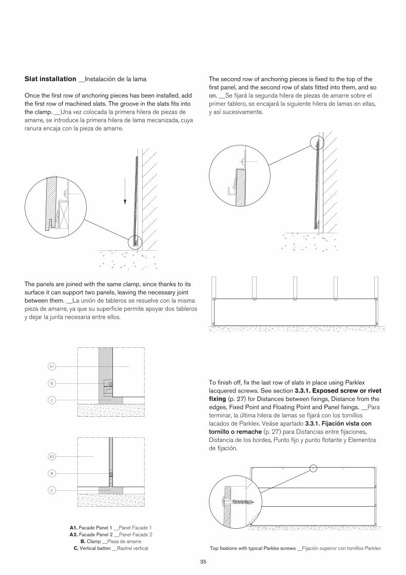
35
The second row of anchoring pieces is fixed to the top of the first panel, and the second row of slats fitted into them, and so on. __Se fijará la segunda hilera de piezas de amarre sobre el primer tablero, se encajará la siguiente hilera de lamas en ellas, y así sucesivamente.
To finish off, fix the last row of slats in place using Parklex lacquered screws. See section 3.3.1. Exposed screw or rivet fixing (p. 27) for Distances between fixings, Distance from the edges, Fixed Point and Floating Point and Panel fixings. __Para terminar, la última hilera de lamas se fijará con los tornillos lacados de Parklex. Veáse apartado 3.3.1. Fijación vista con tornillo o remache (p. 27) para Distancias entre fijaciones, Distancia de los bordes, Punto fijo y punto flotante y Elementos de fijación.
Slat installation __Instalación de la lama
Once the first row of anchoring pieces has been installed, add the first row of machined slats. The groove in the slats fits into the clamp. __Una vez colocada la primera hilera de piezas de amarre, se introduce la primera hilera de lama mecanizada, cuya ranura encaja con la pieza de amarre.
The panels are joined with the same clamp, since thanks to its surface it can support two panels, leaving the necessary joint between them. __La unión de tableros se resuelve con la misma pieza de amarre, ya que su superficie permite apoyar dos tableros y dejar la junta necesaria entre ellos.
Top fixations with typical Parklex screws __Fijación superior con tornillos Parklex
A1. Facade Panel 1 __Panel Facade 1A2. Facade Panel 2 __Panel Facade 2
B. Clamp __Pieza de amarreC. Vertical batten __Rastrel vertical
C
C
A1
A2
B
B
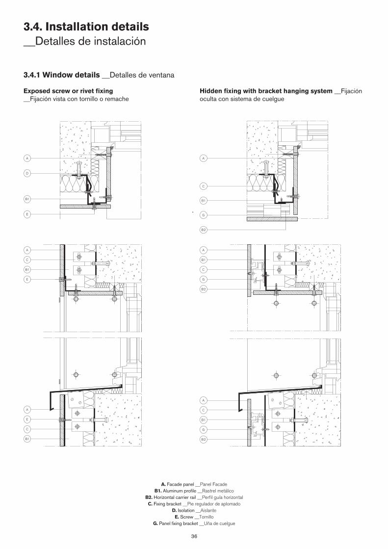
36
3.4.1 Window details __Detalles de ventana
Exposed screw or rivet fixing __Fijación vista con tornillo o remache
Hidden fixing with bracket hanging system __Fijación oculta con sistema de cuelgue
A. Facade panel __Panel FacadeB1. Aluminum profile __Rastrel metálico
B2. Horizontal carrier rail __Perfil guía horizontalC. Fixing bracket __Pie regulador de aplomado
D. Isolation __AislanteE. Screw __Tornillo
G. Panel fixing bracket __Uña de cuelgue
3.4. Installation details __Detalles de instalación
A A
A A
A
A
D
C
C B1
C
C
B1 C
B1
B2
B2
E G
G
B1 B1
E G
B2
E
B1
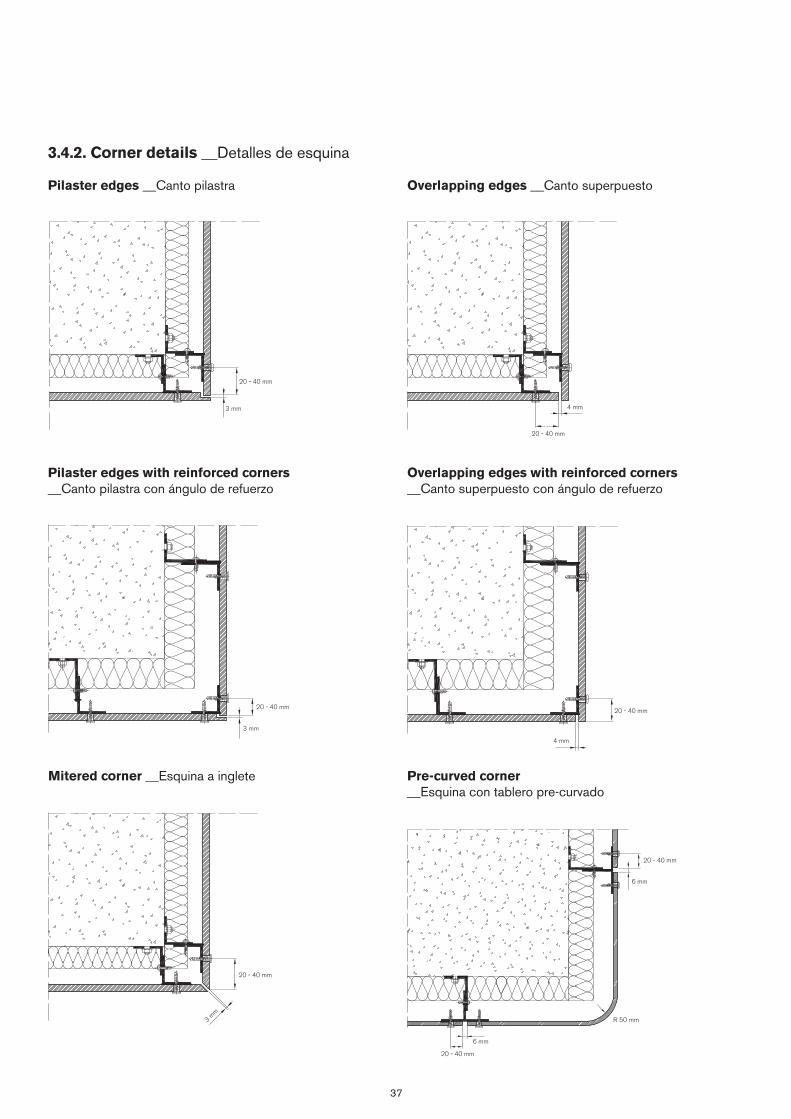
37
3.4.2. Corner details __Detalles de esquina
Pilaster edges __Canto pilastra
Pilaster edges with reinforced corners __Canto pilastra con ángulo de refuerzo
Overlapping edges __Canto superpuesto
Overlapping edges with reinforced corners __Canto superpuesto con ángulo de refuerzo
Pre-curved corner __Esquina con tablero pre-curvado
Mitered corner __Esquina a inglete
20 - 40 mm
20 - 40 mm
20 - 40 mm
20 - 40 mm
20 - 40 mm
20 - 40 mm
R 50 mm
20 - 40 mm
3 mm
3 mm
3 mm
4 mm
6 mm
6 mm
4 mm


4. Louvre installation system __Sistema de instalación en celosías
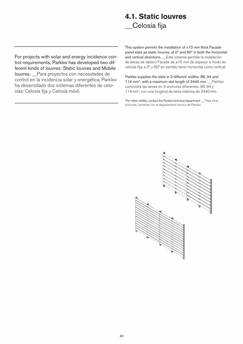
40
This system permits the installation of ≥10 mm thick Facade panel slats as static louvres, at 0º and 60º in both the horizontal and vertical directions. __Este sistema permite la instalación de lamas de tablero Facade de ≥10 mm de espesor a modo de celosía fija, a 0º y 60º en sentido tanto horizontal como vertical.
Parklex supplies the slats in 3 different widths: 86, 94 and 114 mm*, with a maximum slat length of 2440 mm. __Parklex suministra las lamas en 3 anchuras diferentes: 86, 94 y 114 mm*, con una longitud de lama máxima de 2440 mm.
*For other widths, contact the Parklex technical department. __*Para otras anchuras, contactar con el departamento técnico de Parklex.
4.1. Static louvres __Celosía fija
For projects with solar and energy incidence con-trol requirements, Parklex has developed two dif-ferent kinds of louvres: Static louvres and Mobile louvres. __Para proyectos con necesidades de control en la incidencia solar y energética, Parklex ha desarrollado dos sistemas diferentes de celo-sías: Celosía fija y Celosía móvil.

41
4.1.2. Substructure installation __Instalación de la subestructura
The profiles with trim are perforated every 20 mm, making it possible to adjust the louvre design to the needs of each project. __Los perfiles con paso están perforados cada 20 mm*, permitiendo ajustar el diseño de las celosías a las necesidades de cada proyecto.
Once the profiles have been installed, each base piece is held in place at the desired profile level using two stainless steel self-tapping screws (one on each side). __Una vez instalados los perfiles, cada pieza base se amarra con dos tornillos autrorroscantes de acero inoxidable (uno por cada lado) al nivel deseado del perfil.
To join the panels, larger-sized bases should be used. __Para la unión entre tableros, se utilizan bases de mayor dimensión.
4.1.1. Substructure __Subestructura
The first step is to install the profiles with trim to which the louvres will be fitted. To fix these profiles to the wall, Parklex supplies brackets for absorbing irregularities in the façade. __Primero se instalan los perfiles con paso sobre los cuales se instalarán las celosías. Para la fijación de estos perfiles al muro, Parklex suministra pies reguladores de aplomado que permitirán absorber las irregularidades de la fachada.
The direction of the substructure installation (vertical or hori-zontal) will determine the kind of louvre to be installed. Vertical profiles for horizontal louvres and horizontal profiles for vertical louvres (provided that ventilation is guaranteed). __El sentido de colocación de la subestructura (vertical u horizontal) marcará el tipo de celosía que se instalará. Perfiles verticales para celosías horizontales y perfiles horizontales para celosías verticales (siem-pre que se garantice la ventilación).
The substructure alignment is particularly important, given that any imperfection or unevenness would be transferred to the louvre. __La alineación de la subestructura es especialmente importante, ya que cualquier imperfección o desnivel se verían trasladados a la celosía.
Thickness __Espesor Maximum distance __Distancia máxima
10 mm 1220 mm
There must always be at least 3 fixing points in the longitudinal direction of the slat. __Siempre tienen que haber, como mínimo, 3 puntos de fijación en el sentido longitudinal de la lama.
Installation of 60º Louvre base piece __Instalación pieza base
Celosía 60º
Installation of 0º Louvre base piece __Instalación pieza base
Celosía 0º
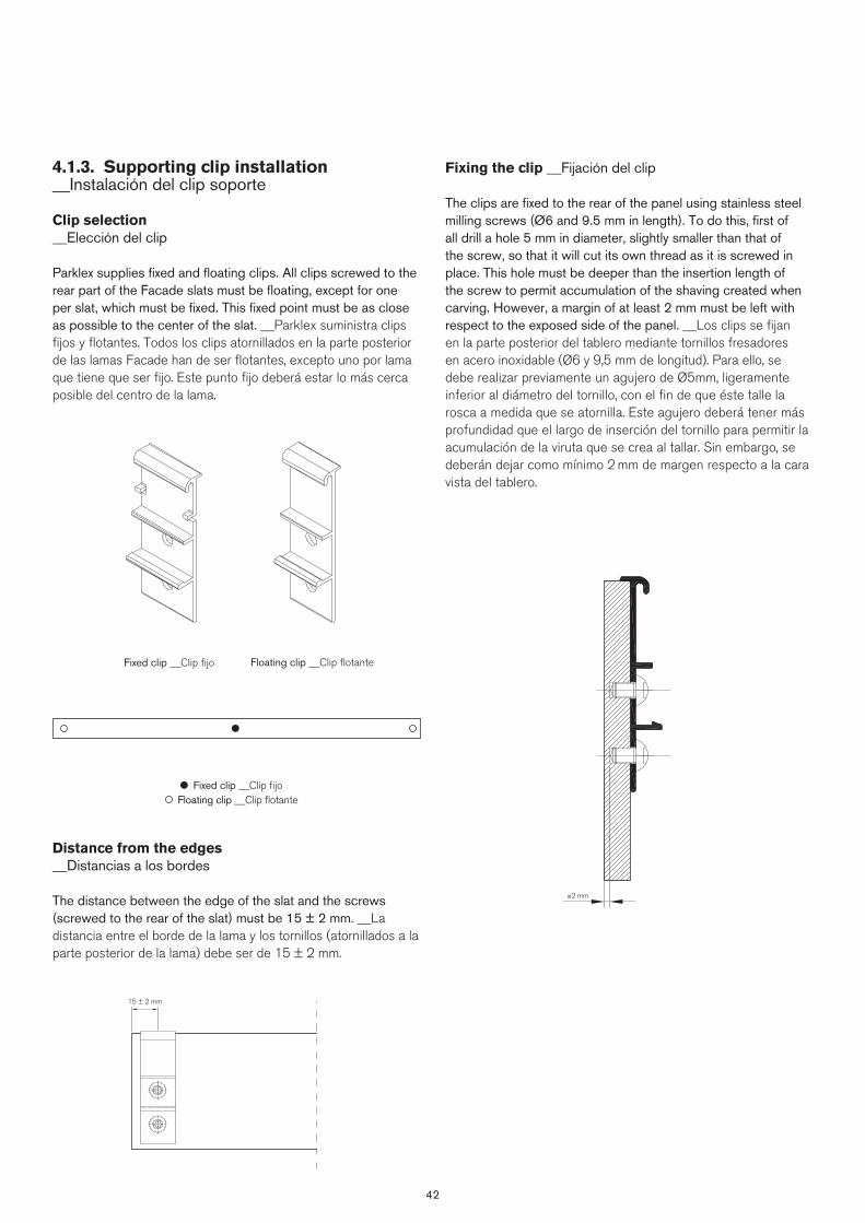
42
Fixing the clip __Fijación del clip
The clips are fixed to the rear of the panel using stainless steel milling screws (Ø6 and 9.5 mm in length). To do this, first of all drill a hole 5 mm in diameter, slightly smaller than that of the screw, so that it will cut its own thread as it is screwed in place. This hole must be deeper than the insertion length of the screw to permit accumulation of the shaving created when carving. However, a margin of at least 2 mm must be left with respect to the exposed side of the panel. __Los clips se fijan en la parte posterior del tablero mediante tornillos fresadores en acero inoxidable (Ø6 y 9,5 mm de longitud). Para ello, se debe realizar previamente un agujero de Ø5mm, ligeramente inferior al diámetro del tornillo, con el fin de que éste talle la rosca a medida que se atornilla. Este agujero deberá tener más profundidad que el largo de inserción del tornillo para permitir la acumulación de la viruta que se crea al tallar. Sin embargo, se deberán dejar como mínimo 2 mm de margen respecto a la cara vista del tablero.
4.1.3. Supporting clip installation __Instalación del clip soporte
Clip selection__Elección del clip
Parklex supplies fixed and floating clips. All clips screwed to the rear part of the Facade slats must be floating, except for one per slat, which must be fixed. This fixed point must be as close as possible to the center of the slat. __Parklex suministra clips fijos y flotantes. Todos los clips atornillados en la parte posterior de las lamas Facade han de ser flotantes, excepto uno por lama que tiene que ser fijo. Este punto fijo deberá estar lo más cerca posible del centro de la lama.
Distance from the edges__Distancias a los bordes
The distance between the edge of the slat and the screws (screwed to the rear of the slat) must be 15 ± 2 mm. __La distancia entre el borde de la lama y los tornillos (atornillados a la parte posterior de la lama) debe ser de 15 ± 2 mm.
Floating clip __Clip flotante
Fixed clip __Clip fijo Floating clip __Clip flotante
Fixed clip __Clip fijo
15 ± 2 mm
≥2 mm
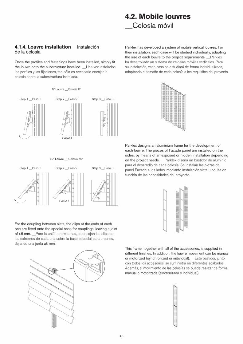
43
4.1.4. Louvre installation __Instalación de la celosía
Once the profiles and fastenings have been installed, simply fit the louvre onto the substructure installed. __Una vez instalados los perfiles y las fijaciones, tan sólo es necesario encajar la celosía sobre la subestructura instalada.
Parklex has developed a system of mobile vertical louvres. For their installation, each case will be studied individually, adapting the size of each louvre to the project requirements. __Parklex ha desarrollado un sistema de celosías móviles verticales. Para su instalación, cada caso se estudiará de forma individualizada, adaptando el tamaño de cada celosía a los requisitos del proyecto.
Parklex designs an aluminium frame for the development of each louvre. The pieces of Facade panel are installed on the sides, by means of an exposed or hidden installation depending on the project needs. __Parklex diseña un bastidor de aluminio para el desarrollo de cada celosía. Se instalan las piezas de panel Facade a los lados, mediante instalación vista u oculta en función de las necesidades del proyecto.
This frame, together with all of the accessories, is supplied in different finishes. In addition, the louvre movement can be manual or motorized (synchronized or individual). __Este bastidor, junto con todos los accesorios, se suministra en diferentes acabados. Además, el movimiento de las celosías se puede realizar de forma manual o motorizada (sincronizada o individual).
4.2. Mobile louvres __Celosía móvil
For the coupling between slats, the clips at the ends of each one are fitted onto the special base for couplings, leaving a joint of ≥6 mm. __Para la unión entre lamas, se encajan los clips de los extremos de cada una sobre la base especial para uniones, dejando una junta ≥6 mm.
0º Louvre __Celosía 0º
Step 1 __Paso 1
Step 1 __Paso 1
Step 2 __Paso 2
Step 2 __Paso 2
Step 3 __Paso 3
Step 3 __Paso 3
60º Louvre __ Celosía 60º


5. Dropped ceiling installation system __Sistema de instalación en falsos techos
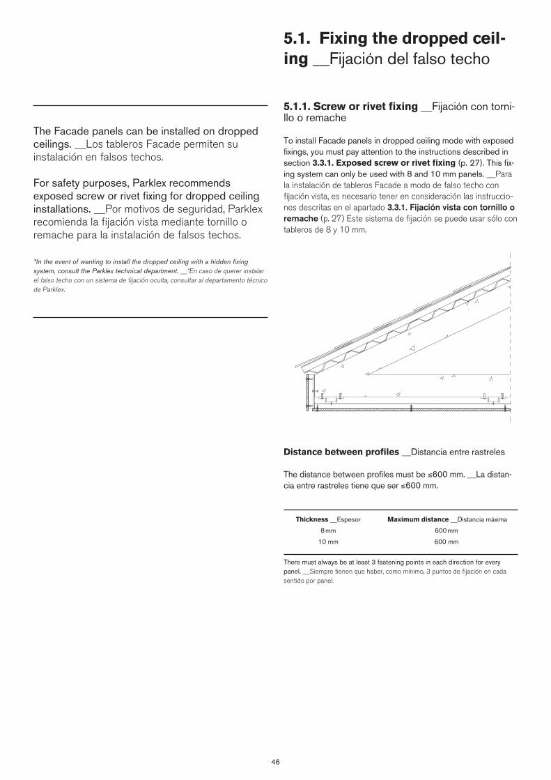
46
5.1.1. Screw or rivet fixing __Fijación con torni-llo o remache To install Facade panels in dropped ceiling mode with exposed fixings, you must pay attention to the instructions described in section 3.3.1. Exposed screw or rivet fixing (p. 27). This fix-ing system can only be used with 8 and 10 mm panels. __Para la instalación de tableros Facade a modo de falso techo con fijación vista, es necesario tener en consideración las instruccio-nes descritas en el apartado 3.3.1. Fijación vista con tornillo o remache (p. 27) Este sistema de fijación se puede usar sólo con tableros de 8 y 10 mm.
Distance between profiles __Distancia entre rastreles
The distance between profiles must be ≤600 mm. __La distan-cia entre rastreles tiene que ser ≤600 mm.
Thickness __Espesor Maximum distance __Distancia máxima
8 mm 600 mm
10 mm 600 mm
There must always be at least 3 fastening points in each direction for every panel. __Siempre tienen que haber, como mínimo, 3 puntos de fijación en cada sentido por panel.
5.1. Fixing the dropped ceil-ing __Fijación del falso techo
The Facade panels can be installed on dropped ceilings. __Los tableros Facade permiten su instalación en falsos techos.
For safety purposes, Parklex recommends exposed screw or rivet fixing for dropped ceiling installations. __Por motivos de seguridad, Parklex recomienda la fijación vista mediante tornillo o remache para la instalación de falsos techos.
*In the event of wanting to install the dropped ceiling with a hidden fixing system, consult the Parklex technical department. __*En caso de querer instalar el falso techo con un sistema de fijación oculta, consultar al departamento técnico de Parklex.


6. Installation system in curves __Sistema de instalación en curvas
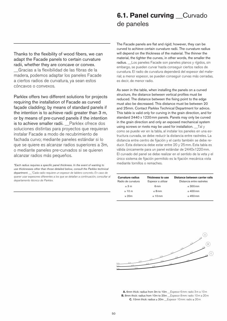
50
The Facade panels are flat and rigid; however, they can be curved to achieve certain curvature radii. The curvature radius will depend on the thickness of the material. The thinner the material, the tighter the curves, in other words, the smaller the radius. __Los paneles Facade son paneles planos y rígidos, sin embargo, se pueden curvar hasta conseguir ciertos radios de curvatura. El radio de curvatura dependerá del espesor del mate-rial; a menor espesor, se pueden conseguir curvas más cerradas, es decir, de menor radio.
As seen in the table, when installing the panels on a curved structure, the distance between vertical profiles must be reduced. The distance between the fixing point to the edge must also be decreased. This distance must be between 20 and 25mm. Contact Parklex Technical Department for advice. This table is valid only for curving in the grain direction, and for standard 2440 x 1220 mm panels. Panels may only be curved in the grain direction and only an exposed mechanical system using screws or rivets may be used for installation. __Tal y como se puede ver en la tabla, al instalar los paneles en una es-tructura curvada, se debe reducir la distancia entre rastreles. La distancia entre centro de fijación y el canto también se debe re-ducir. Esta distancia debe estar entre 20 y 25 mm. Esta tabla es válida únicamente para un panel estándar de 2440x1220 mm. El curvado del panel se debe realizar en el sentido de la veta y el único sistema de fijación permitido es la fijación mecánica vista mediante tornillos o remaches.
Curvature radius Thickness to use Distance between carrier rails Radio de curvatura Espesor a utilizar Distancia entre rastreles
≥ 3 m 6 mm ≤ 300 mm
≥ 10 m ≤ 8 mm ≤ 400 mm
≥ 20m ≤ 10 mm ≤ 450 mm
A. 6mm thick: radius from 3m to 10m __Espesor 6 mm: radio 3 m a 10 mB. 8mm thick: radius from 10m to 20m __Espesor 8 mm: radio 10 m a 20 m
C. 10mm thick: radius ≥ 20m __Espesor 10 mm: radio ≥ 20 m
6.1. Panel curving __Curvado de paneles
Thanks to the flexibility of wood fibers, we can adapt the Facade panels to certain curvature radii, whether they are concave or convex. __Gracias a la flexibilidad de las fibras de la madera, podemos adaptar los paneles Facade a ciertos radios de curvatura, ya sean estos cóncavos o convexos.
Parklex offers two different solutions for projects requiring the installation of Facade as curved façade cladding; by means of standard panels if the intention is to achieve radii greater than 3 m, or by means of pre-curved panels if the intention is to achieve smaller radii. __Parklex ofrece dos soluciones distintas para proyectos que requieran instalar Facade a modo de recubrimiento de fachada curvo; mediante paneles estándar si lo que se quiere es alcanzar radios superiores a 3m, o mediante paneles pre-curvados si se quieren alcanzar radios más pequeños.
*Each radius requires a specific panel thickness. In the event of wanting to use thicknesses other than those detailed below, consult the Parklex technical department. __*Cada radio requiere un espesor de tablero concreto. En caso de querer usar espesores diferentes a los que se detallan a continuación, consultar al departamento técnico de Parklex.
A
B
C
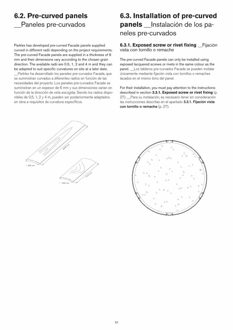
51
Parklex has developed pre-curved Facade panels supplied curved in different radii depending on the project requirements. The pre-curved Facade panels are supplied in a thickness of 6 mm and their dimensions vary according to the chosen grain direction. The available radii are 0.5, 1, 2 and 4 m and they can be adapted to suit specific curvatures on site at a later date. __Parklex ha desarrollado los paneles pre-curvados Facade, que se suministran curvados a diferentes radios en función de las necesidades del proyecto. Los paneles pre-curvados Facade se suministran en un espesor de 6 mm y sus dimensiones varian en función de la dirección de veta escogida. Siendo los radios dispo-nibles de 0,5, 1, 2 y 4 m, pueden ser posteriormente adaptados en obra a requisitos de curvatura específicos.
6.2. Pre-curved panels __Paneles pre-curvados
6.3. Installation of pre-curved panels __Instalación de los pa-neles pre-curvados
6.3.1. Exposed screw or rivet fixing __Fijación vista con tornillo o remache The pre-curved Facade panels can only be installed using exposed lacquered screws or rivets in the same colour as the panel. __Los tableros pre-curvados Facade se pueden instalar únicamente mediante fijación vista con tornillos o remaches lacados en el mismo tono del panel.
For their installation, you must pay attention to the instructions described in section 3.3.1. Exposed screw or rivet fixing (p. 27). __Para su instalación, es necesario tener en consideración las instrucciones descritas en el apartado 3.3.1. Fijación vista con tornillo o remache (p. 27).
595 mm
2440 mm
595 mm
1210 mm

52
6.4. Technical datasheet __Ficha técnica
Tests Standard Property or attribute Measurement unit Result
1. Inspection requirements
Parklex Facade CurvedRef: FTFACADEC
Rev: 03 (04.2015)
Colour, pattern and surface finish EN 438-8 Part 5.2.2.3 Due to the fact that wood is a natural product, each veneer may be considered as unique. Colour and structure differences are considered as normal. Singularities such as knots and resin inclusions are not considered as defects, but as a part of the décor. There are differences in light fastness performances depending on the wood species and the source of the wood.
2. Dimensional tolerances
595 mm
2440 mm
595 mm
1220 mm
Thickness: 6 mmCurvature radius: 500, 1000, 2000, 4000 mm
Dimensional Tolerances: 10%
3. Physical properties
Resistance to impact with large diameter ball
EN 438-2 Part 21 Maximum height for which no visible surface cracking or imprint greater than 10mm
mm ≥ 1800
Determination of graffiti resistance ASTM D 6578:2000 Cleanability level Permanent blue marker 4
Spray red paint 4
Wax black crayon 1
Water based black marker 2
4. Weather resistance requirements
Resistance to UV light EN 438-2 Part 28 Rating according to EN 20105 – A02
Contrast Grey scale rating ≥ 3
Appearance Rating ≥ 4
Resistance to artificial weathering (including light fastness)
EN 438-2 Part 29 Rating according to EN 20105 – A02
Contrast Grey scale rating ≥ 3
Appearance Rating ≥ 4
5. Safety requirements
Water vapour permeability EN 438-7 Part 4.4 Wet cup method µ 110
Dry cup method 250
Resistance to fixings EN 438-7 Part 4.5 Screw holding value N > 2000
Density EN ISO 1.183 Density g/cm3 ≥ 1,35
Resistance to wet conditions EN 438-2 Part 15 Moisture absorbed % ≤ 5
Appearance Rating ≥ 4
6. Reaction to fire
Reaction to fire EN 13.501-1 Euroclass Classification D-s2,d0 (1)
(1) CWFT: Classified Without Further Testing according to EN 438 Part 7, 4.2.3. Screw or rivet fixing is recommended. Other fixing systems must be consulted with technical department.
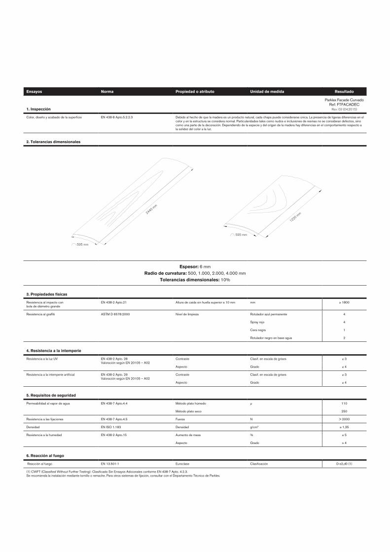
Ensayos Norma Propiedad o atributo Unidad de medida Resultado
1. Inspección
Parklex Facade CurvadoRef: FTFACADEC
Rev: 03 (04.2015)
Color, diseño y acabado de la superficie EN 438-8 Apto.5.2.2.3 Debido al hecho de que la madera es un producto natural, cada chapa puede considerarse única. La presencia de ligeras diferencias en el color y en la estructura se considera normal. Particularidades tales como nudos e inclusiones de resinas no se consideran defectos, sino como una parte de la decoración. Dependiendo de la especie y del origen de la madera hay diferencias en el comportamiento respecto a la solidez del color a la luz.
2. Tolerancias dimensionales
595 mm
2440 mm
595 mm
1220 mm
Espesor: 6 mmRadio de curvatura: 500, 1.000, 2.000, 4.000 mm
Tolerancias dimensionales: 10%
3. Propiedades físicas
Resistencia al impacto con bola de diámetro grande
EN 438-2 Apto.21 Altura de caída sin huella superior a 10 mm mm ≥ 1800
Resistencia al graffiti ASTM D 6578:2000 Nivel de limpieza Rotulador azul permanente 4
Spray rojo 4
Cera negra 1
Rotulador negro en base agua 2
4. Resistencia a la intemperie
Resistencia a la luz UV EN 438-2 Apto. 28 Valoración según EN 20105 – A02
Contraste Clasif. en escala de grises ≥ 3
Aspecto Grado ≥ 4
Resistencia a la intemperie artificial EN 438-2 Apto. 29 Valoración según EN 20105 – A02
Contraste Clasif. en escala de grises ≥ 3
Aspecto Grado ≥ 4
5. Requisitos de seguridad
Permeabilidad al vapor de agua EN 438-7 Apto.4.4 Método plato húmedo µ 110
Método plato seco 250
Resistencia a las fijaciones EN 438-7 Apto.4.5 Fuerza N > 2000
Densidad EN ISO 1.183 Densidad g/cm3 ≥ 1,35
Resistencia a la humedad EN 438-2 Apto.15 Aumento de masa % ≤ 5
Aspecto Grado ≥ 4
6. Reacción al fuego
Reacción al fuego EN 13.501-1 Euroclase Clasificación D-s2,d0 (1)
(1) CWFT (Classified Without Further Testing): Clasificado Sin Ensayos Adicionales conforme EN 438-7 Apto. 4.2.3. Se recomienda la instalación mediante tornillo o remache. Para otros sistemas de fijación, consultar con el Departamento Técnico de Parklex.
Catalogue printed in Pamplona __Catálogo impreso en PamplonaJune 2015 __Junio 2015
Printed by __ImprimeGráficas Ulzama
Paper __Papel: Fedrigoni Arcoprint 1 E.W. 90 grs.
ParklexCOMPOSITES GUREA, S.A.
Zalain auzoa, 13 - 31780 Bera - Navarra - SpainTel. +34 948 625 045 - Fax. +34 948 625 015
[email protected] - www.parklex.com


Fac
ade
tech
nica
l gui
de _
_Fac
ade
guía
técn
ica
Par
klex
201
5
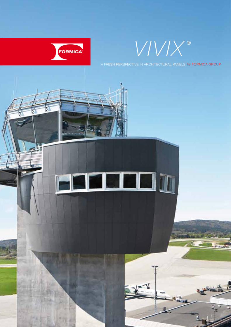

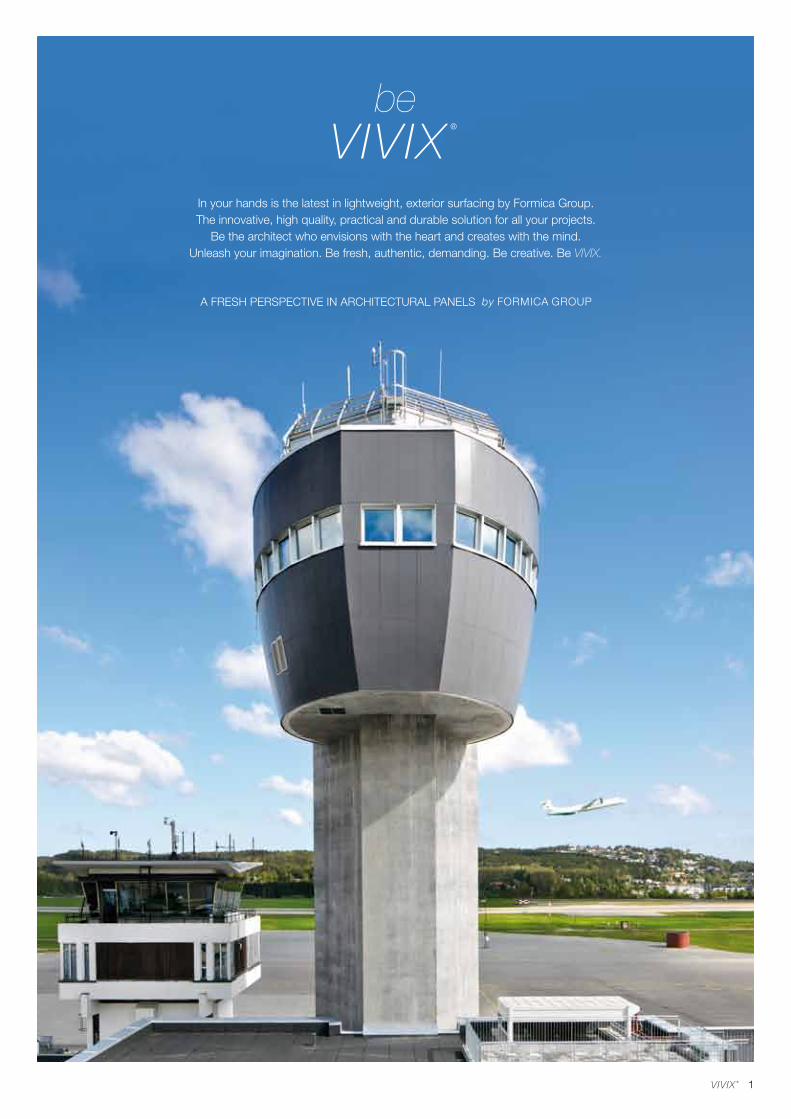
1
In your hands is the latest in lightweight, exterior surfacing by Formica Group. The innovative, high quality, practical and durable solution for all your projects.
Be the architect who envisions with the heart and creates with the mind.Unleash your imagination. Be fresh, authentic, demanding. Be creative. Be VIVIX.
be

2
“VIVIX panels are the ideal solution for this project. The panels are easily machined and can be cut into a variety of shapes and sizes. The control towers are at least 30 metres above ground; the material we used for cladding had to be lightweight for ease of installation and safety as well as versatile and flexible to allow us to realize the design concept.”
Roald Bakke Architect
KRISTIANSAND AIRPORT
PROJECT: air traffic control tower
LOCATION: Kjevik, Norway
DESIGNER: Archus Architects and Wiig og Horgmo Architects
MATERIAL: VIVIX® F7912 Storm
APPLICATION: control tower cladding
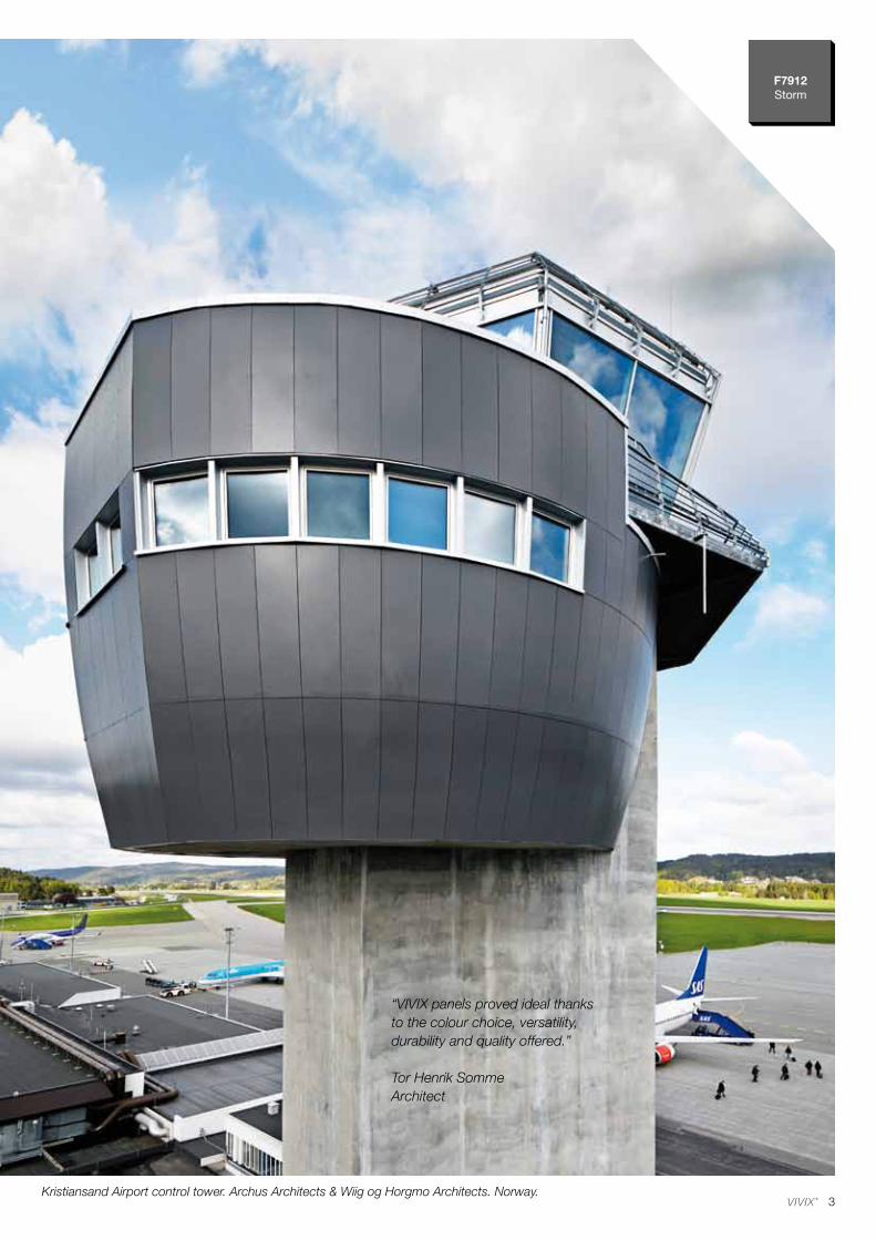
3
F7912Storm
Kristiansand Airport control tower. Archus Architects & Wiig og Horgmo Architects. Norway.
“VIVIX panels proved ideal thanks to the colour choice, versatility, durability and quality offered.”
Tor Henrik SommeArchitect
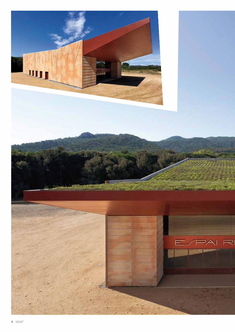
4
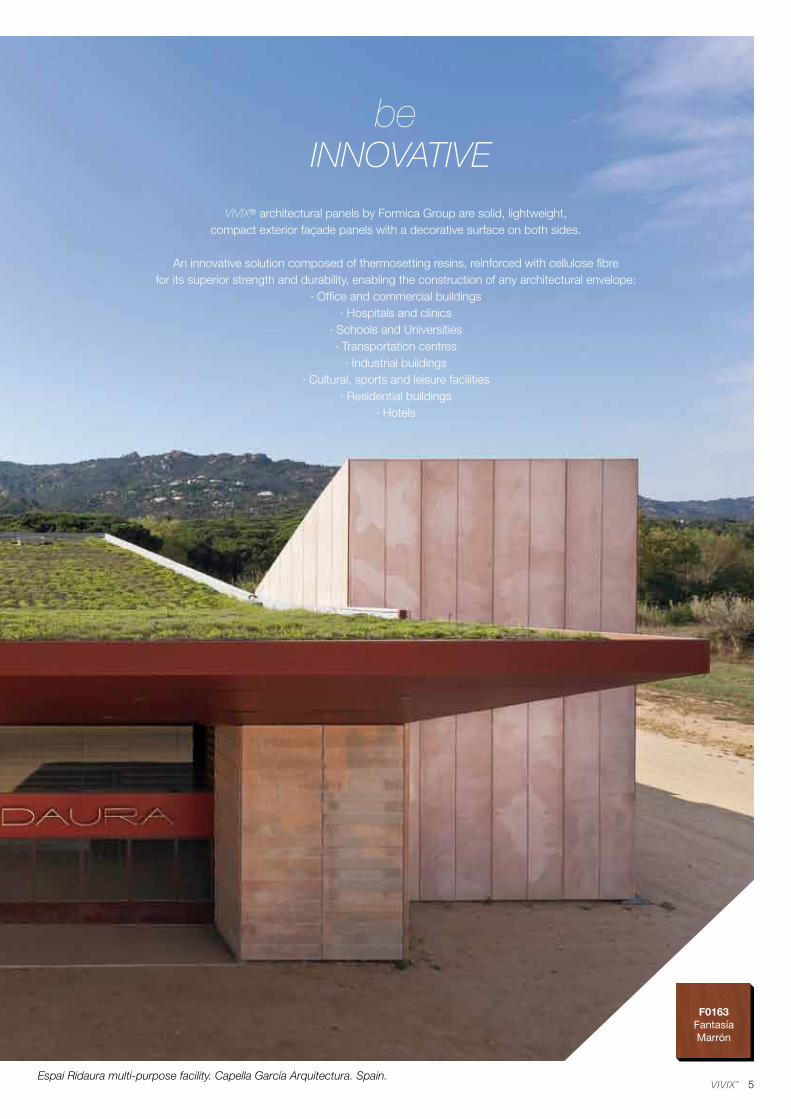
5
F0163FantasíaMarrón
VIVIX® architectural panels by Formica Group are solid, lightweight, compact exterior façade panels with a decorative surface on both sides.
An innovative solution composed of thermosetting resins, reinforced with cellulose fibrefor its superior strength and durability, enabling the construction of any architectural envelope:
· Office and commercial buildings· Hospitals and clinics
· Schools and Universities· Transportation centres
· Industrial buildings· Cultural, sports and leisure facilities
· Residential buildings· Hotels
INNOVATIVEbe
Espai Ridaura multi-purpose facility. Capella García Arquitectura. Spain.

6
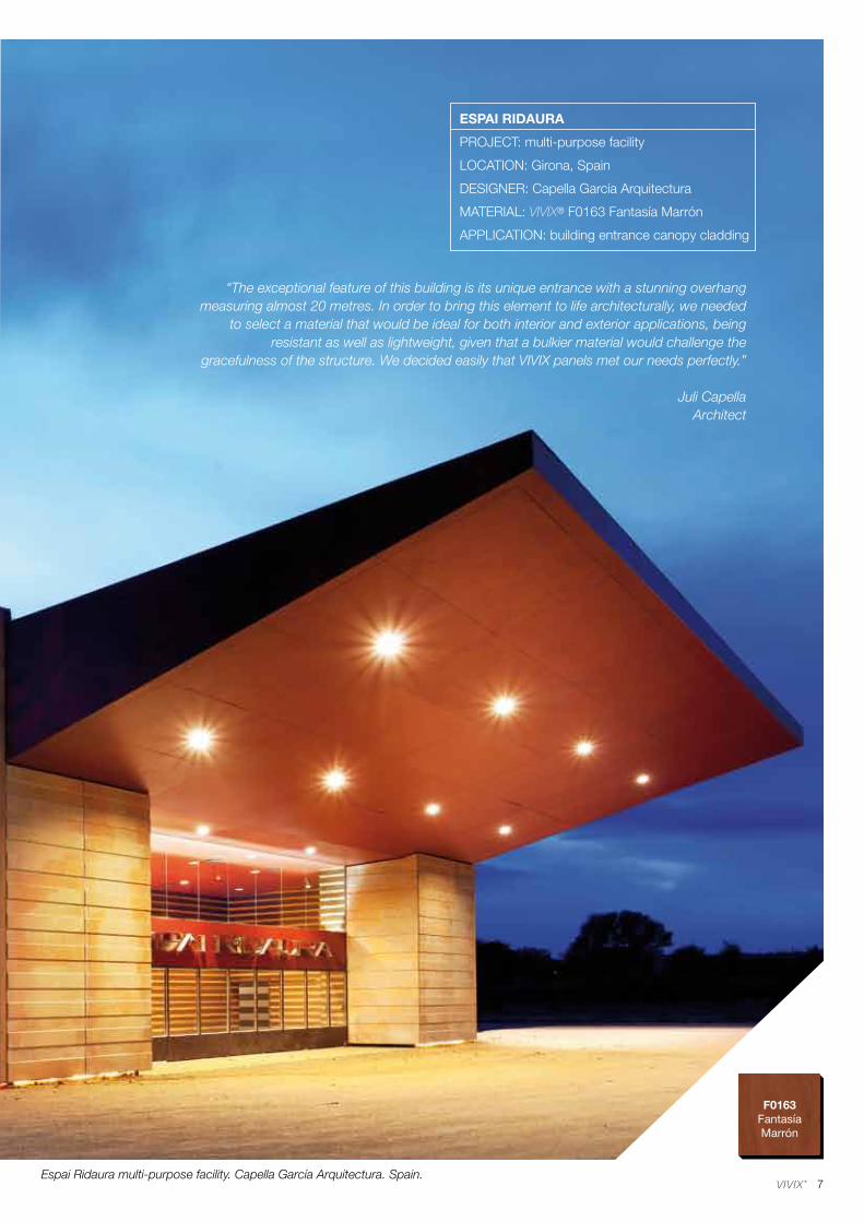
7
F0163FantasíaMarrón
Espai Ridaura multi-purpose facility. Capella García Arquitectura. Spain.
“The exceptional feature of this building is its unique entrance with a stunning overhang measuring almost 20 metres. In order to bring this element to life architecturally, we needed
to select a material that would be ideal for both interior and exterior applications, being resistant as well as lightweight, given that a bulkier material would challenge the
gracefulness of the structure. We decided easily that VIVIX panels met our needs perfectly.”
Juli CapellaArchitect
ESPAI RIDAURA
PROJECT: multi-purpose facility
LOCATION: Girona, Spain
DESIGNER: Capella García Arquitectura
MATERIAL: VIVIX® F0163 Fantasía Marrón
APPLICATION: building entrance canopy cladding
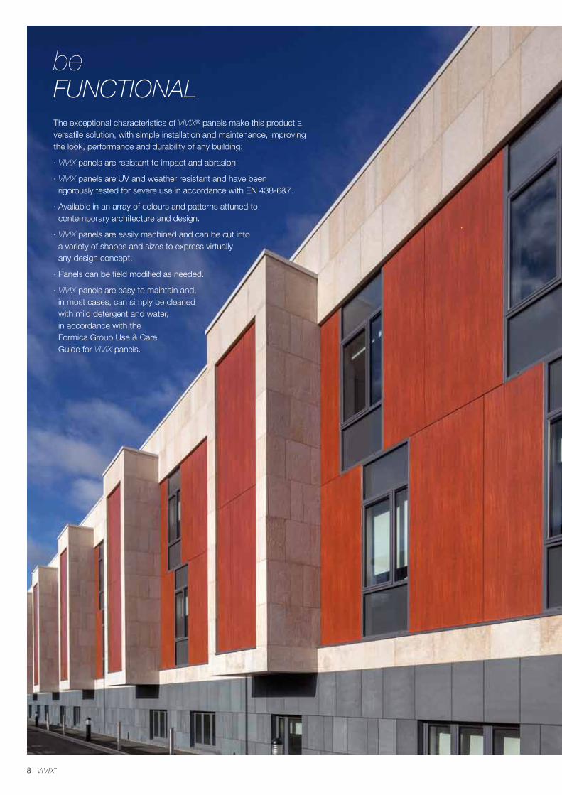
8
The exceptional characteristics of VIVIX® panels make this product a versatile solution, with simple installation and maintenance, improving the look, performance and durability of any building:
· VIVIX panels are resistant to impact and abrasion.
· VIVIX panels are UV and weather resistant and have been rigorously tested for severe use in accordance with EN 438-6&7.
· Available in an array of colours and patterns attuned to contemporary architecture and design.
· VIVIX panels are easily machined and can be cut into a variety of shapes and sizes to express virtually any design concept.
· Panels can be field modified as needed.
· VIVIX panels are easy to maintain and, in most cases, can simply be cleaned with mild detergent and water, in accordance with the Formica Group Use & Care Guide for VIVIX panels.
FUNCTIONALbe
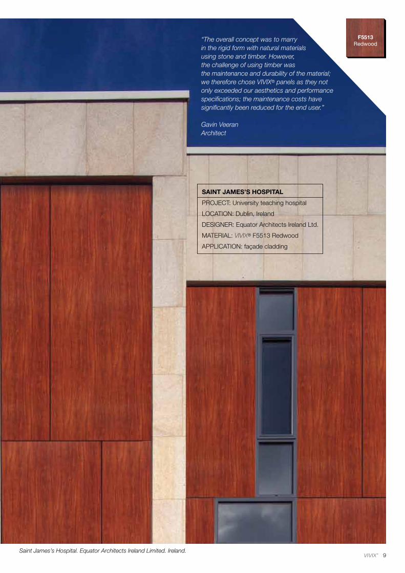
9
F5513Redwood
Saint James’s Hospital. Equator Architects Ireland Limited. Ireland.
“The overall concept was to marry in the rigid form with natural materials using stone and timber. However, the challenge of using timber was the maintenance and durability of the material;we therefore chose VIVIX® panels as they not only exceeded our aesthetics and performance specifications; the maintenance costs have significantly been reduced for the end user.”
Gavin VeeranArchitect
SAINT JAMES’S HOSPITAL
PROJECT: University teaching hospital
LOCATION: Dublin, Ireland
DESIGNER: Equator Architects Ireland Ltd.
MATERIAL: VIVIX® F5513 Redwood
APPLICATION: façade cladding
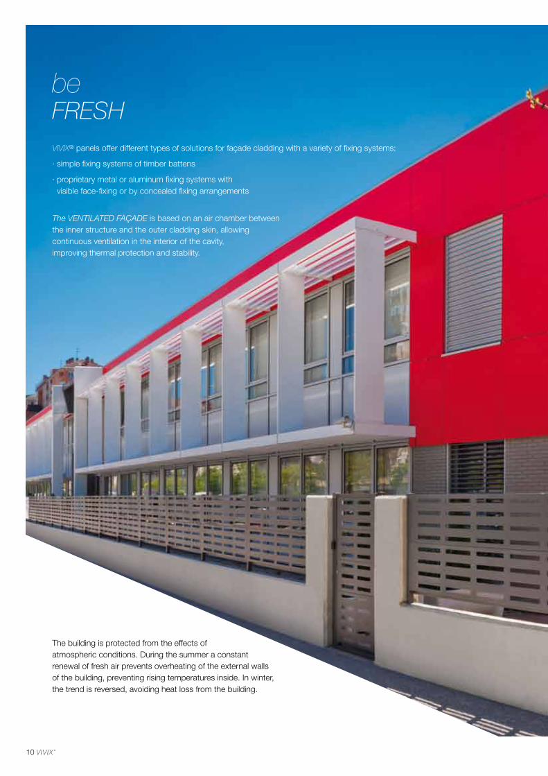
10
The building is protected from the effects of atmospheric conditions. During the summer a constant renewal of fresh air prevents overheating of the external walls of the building, preventing rising temperatures inside. In winter, the trend is reversed, avoiding heat loss from the building.
VIVIX® panels offer different types of solutions for façade cladding with a variety of fixing systems:
· simple fixing systems of timber battens
· proprietary metal or aluminum fixing systems with visible face-fixing or by concealed fixing arrangements
The VENTILATED FAÇADE is based on an air chamber between the inner structure and the outer cladding skin, allowing continuous ventilation in the interior of the cavity,improving thermal protection and stability.
FRESHbe
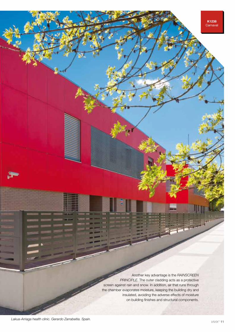
K1238 Carnaval
11Lakua-Arriaga health clinic. Gerardo Zarrabeitia. Spain.
Another key advantage is the RAINSCREEN PRINCIPLE. The outer cladding acts as a protective
screen against rain and snow. In addition, air that runs through the chamber evaporates moisture, keeping the building dry and
insulated, avoiding the adverse effects of moisture on building finishes and structural components.
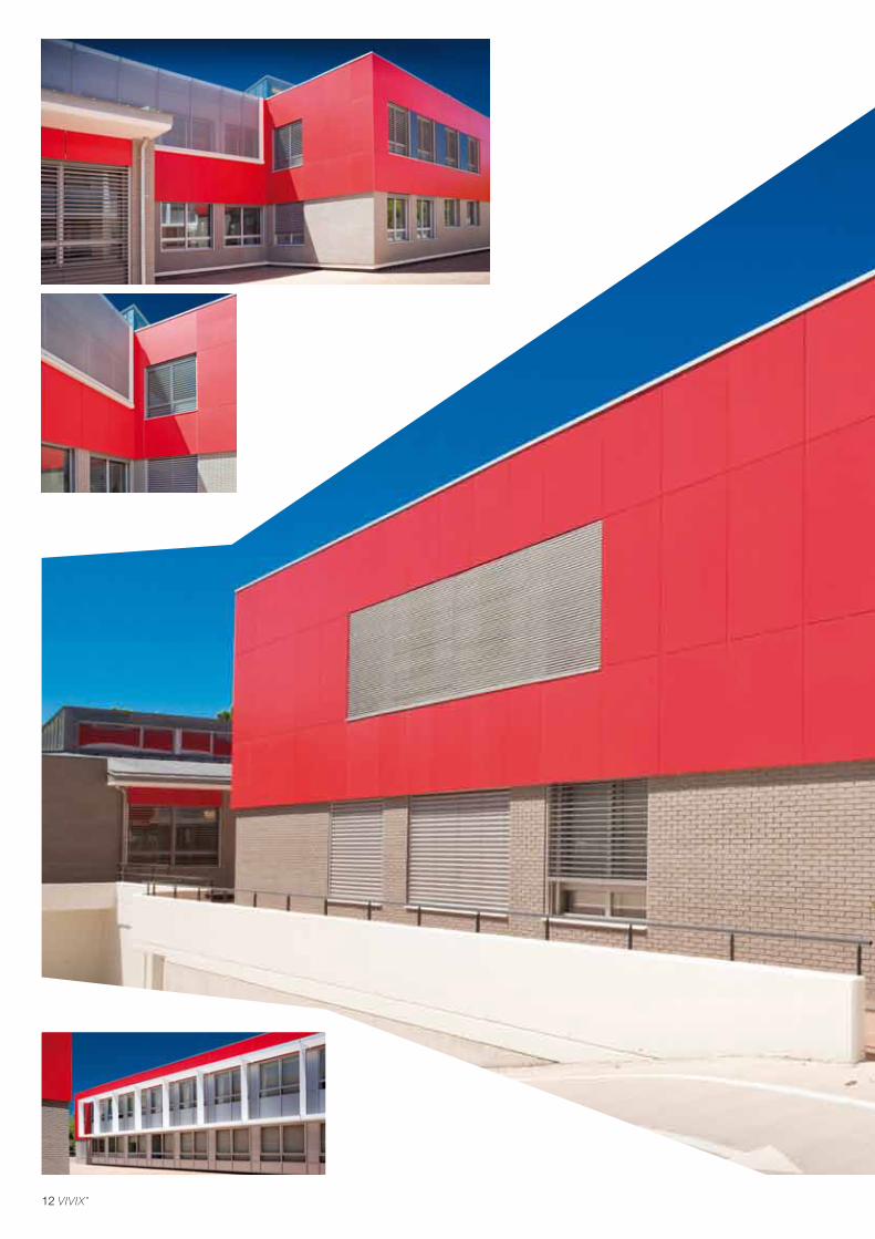
12
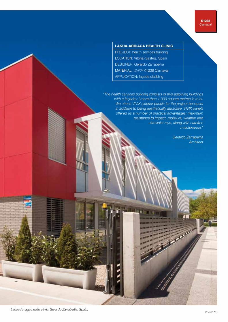
13
K1238 Carnaval
Lakua-Arriaga health clinic. Gerardo Zarrabeitia. Spain.
“The health services building consists of two adjoining buildings with a façade of more than 1,000 square metres in total. We chose VIVIX exterior panels for the project because, in addition to being aesthetically attractive, VIVIX panels offered us a number of practical advantages: maximum
resistance to impact, moisture, weather and ultraviolet rays, along with carefree
maintenance.”
Gerardo ZarrabeitiaArchitect
LAKUA-ARRIAGA HEALTH CLINIC
PROJECT: health services building
LOCATION: Vitoria-Gasteiz, Spain
DESIGNER: Gerardo Zarrabeitia
MATERIAL: VIVIX® K1238 Carnaval
APPLICATION: façade cladding
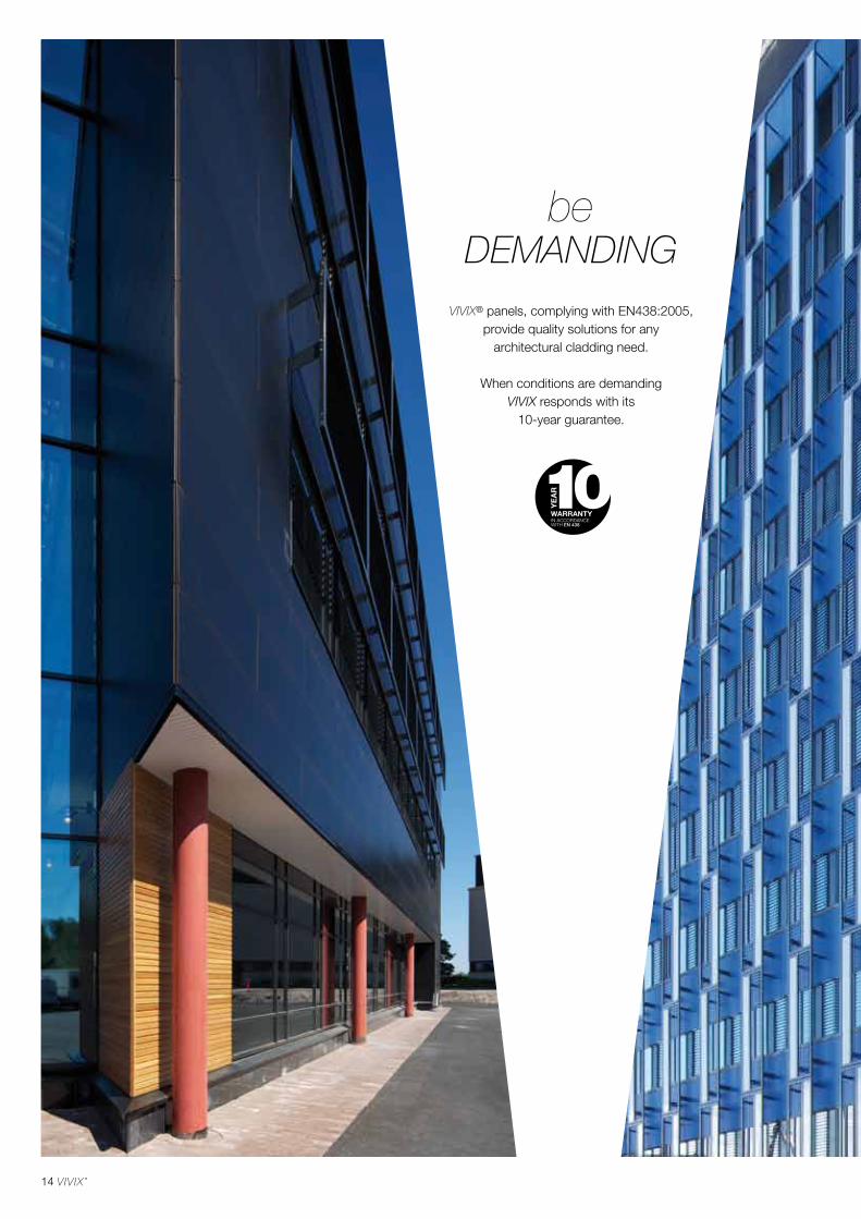
14
VIVIX® panels, complying with EN438:2005, provide quality solutions for any
architectural cladding need.
When conditions are demanding VIVIX responds with its
10-year guarantee.
DEMANDINGbe
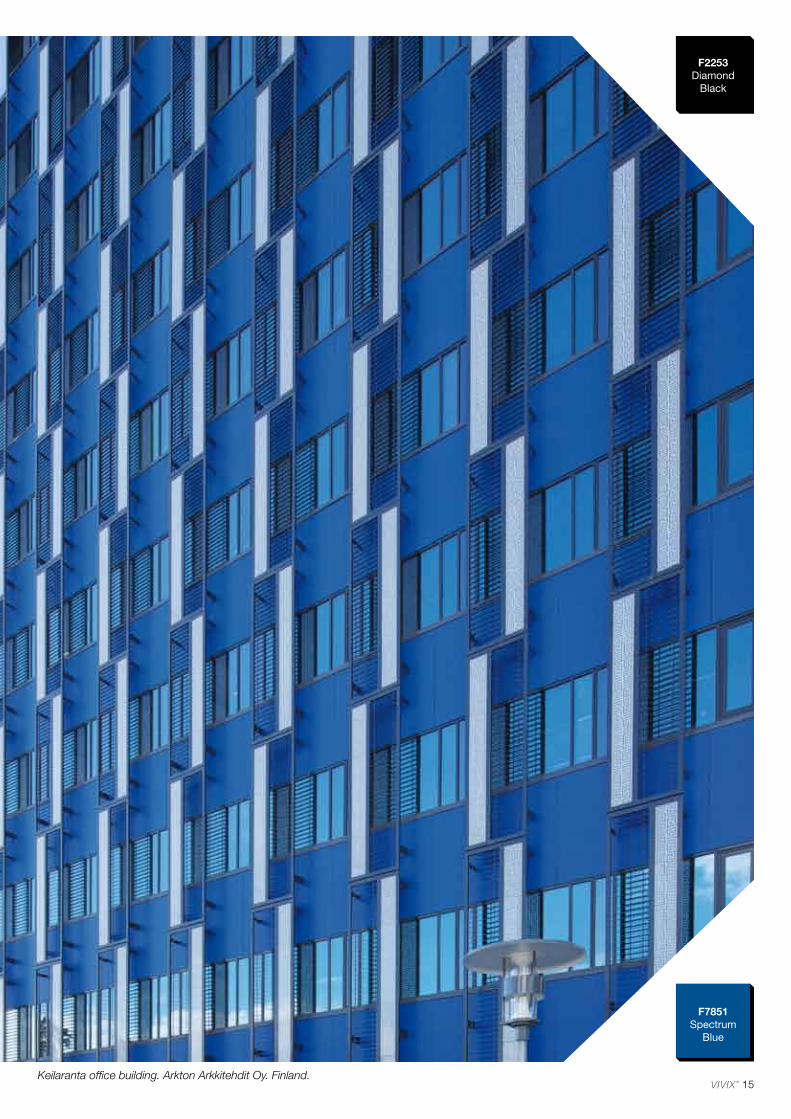
15
F7851Spectrum
Blue
F2253Diamond
Black
Keilaranta office building. Arkton Arkkitehdit Oy. Finland.
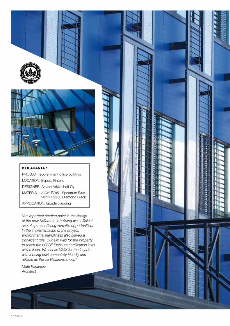
16
“An important starting point in the design of the new Keilaranta 1 building was efficient use of space, offering versatile opportunities. In the implementation of the project, environmental friendliness also played a significant role. Our aim was for the property to reach the LEED® Platinum certification level, which it did. We chose VIVIX for the façade with it being environmentally friendly and reliable as the certifications show.”
Matti Karjanoja Architect
KEILARANTA 1
PROJECT: eco-efficient office building
LOCATION: Espoo, Finland
DESIGNER: Arkton Arkkitehdit Oy
MATERIAL: VIVIX® F7851 Spectrum Blue VIVIX® F2253 Diamond Black
APPLICATION: façade cladding
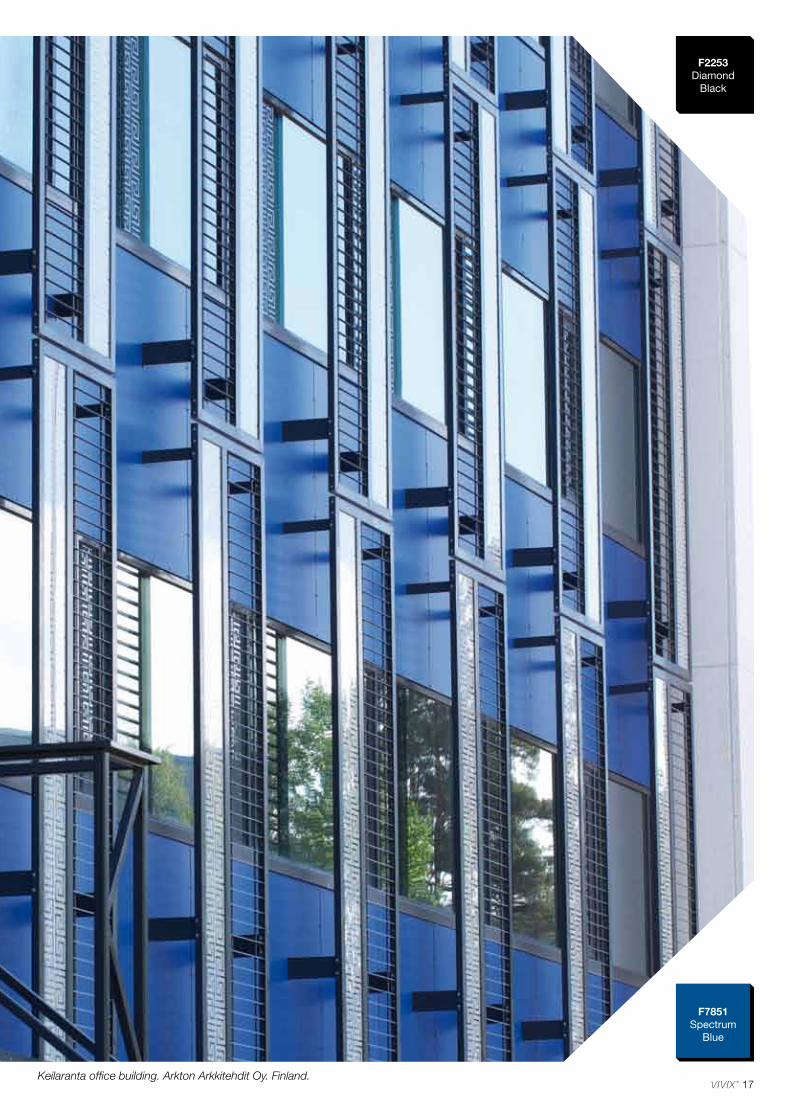
17
F7851Spectrum
Blue
F2253Diamond
Black
Keilaranta office building. Arkton Arkkitehdit Oy. Finland.
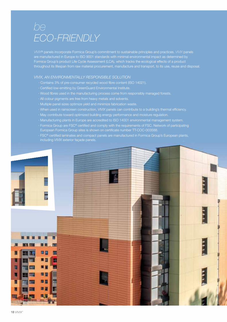
18
ECO-FRIENDLYbe
VIVIX® panels incorporate Formica Group’s commitment to sustainable principles and practices. VIVIX panels are manufactured in Europe to ISO 9001 standards with minimal environmental impact as determined by Formica Group’s product Life Cycle Assessment (LCA), which tracks the ecological effects of a product throughout its lifespan from raw material procurement, manufacture and transport, to its use, reuse and disposal.
VIVIX, AN ENVIRONMENTALLY RESPONSIBLE SOLUTION · Contains 3% of pre-consumer recycled wood fibre content (ISO 14021).
· Certified low-emitting by GreenGuard Environmental Institute.
· Wood fibres used in the manufacturing process come from responsibly managed forests.
· All colour pigments are free from heavy metals and solvents.
· Multiple panel sizes optimize yield and minimize fabrication waste.
· When used in rainscreen construction, VIVIX panels can contribute to a building’s thermal efficiency.
· May contribute toward optimized building energy performance and moisture regulation.
· Manufacturing plants in Europe are accredited to ISO 14001 environmental management system.
· Formica Group are FSC® certified and comply with the requirements of FSC. Network of participating European Formica Group sites is shown on certificate number TT-COC-003588.
· FSC® certified laminates and compact panels are manufactured in Formica Group’s European plants, including VIVIX exterior façade panels.
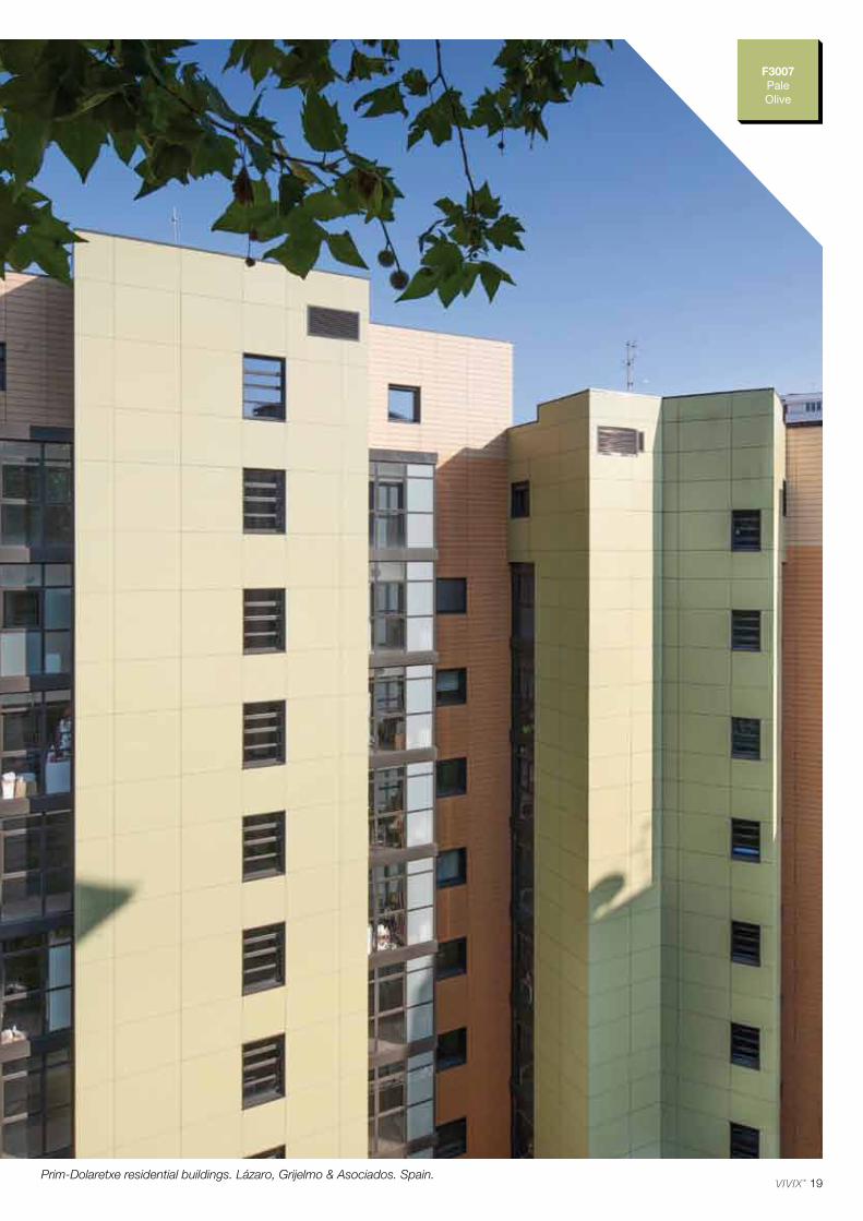
19
F3007PaleOlive
Prim-Dolaretxe residential buildings. Lázaro, Grijelmo & Asociados. Spain.
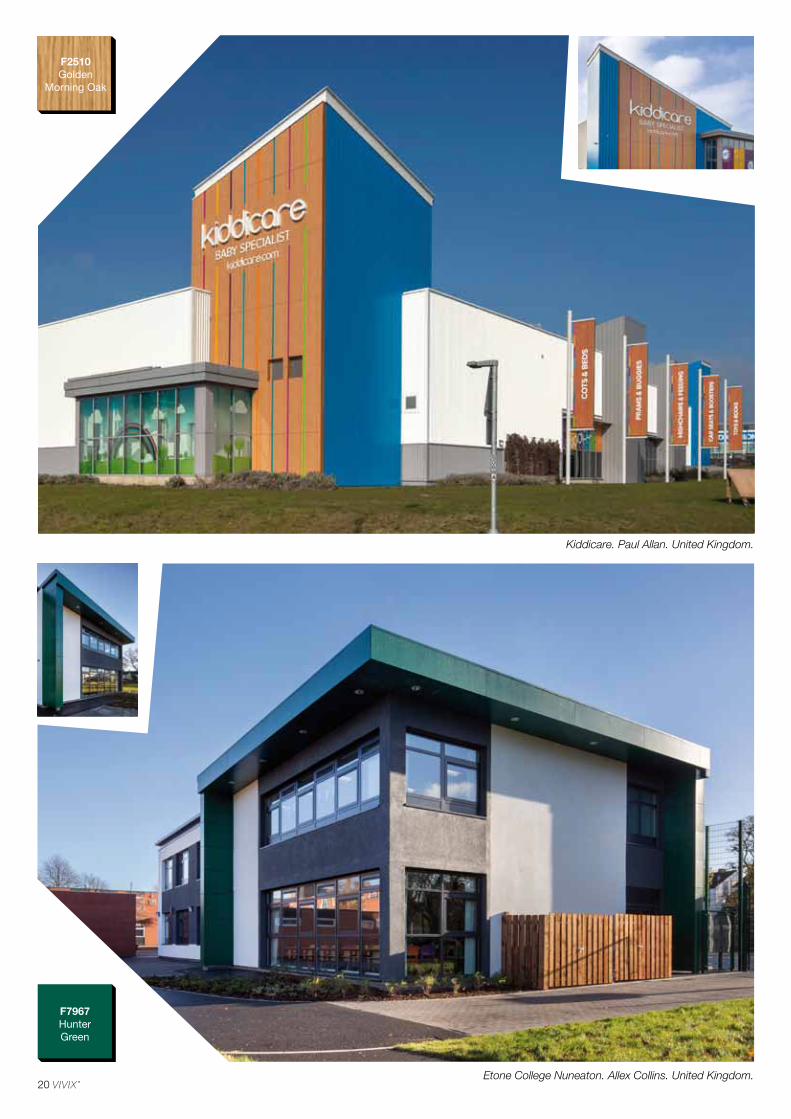
20
F2510Golden
Morning Oak
F7967Hunter Green
Etone College Nuneaton. Allex Collins. United Kingdom.
Kiddicare. Paul Allan. United Kingdom.
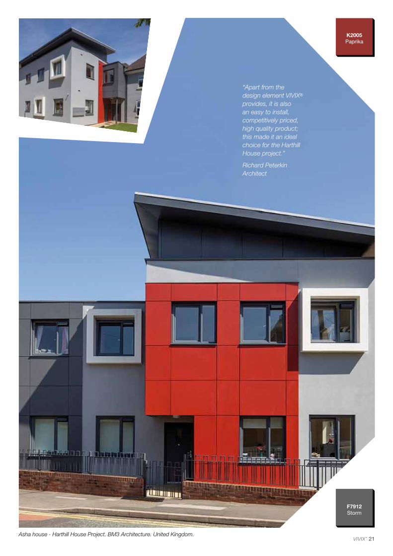
21
F7912Storm
K2005Paprika
Asha house - Harthill House Project. BM3 Architecture. United Kingdom.
“Apart from the design element VIVIX® provides, it is also an easy to install, competitively priced, high quality product; this made it an ideal choice for the Harthill House project.”
Richard Peterkin Architect
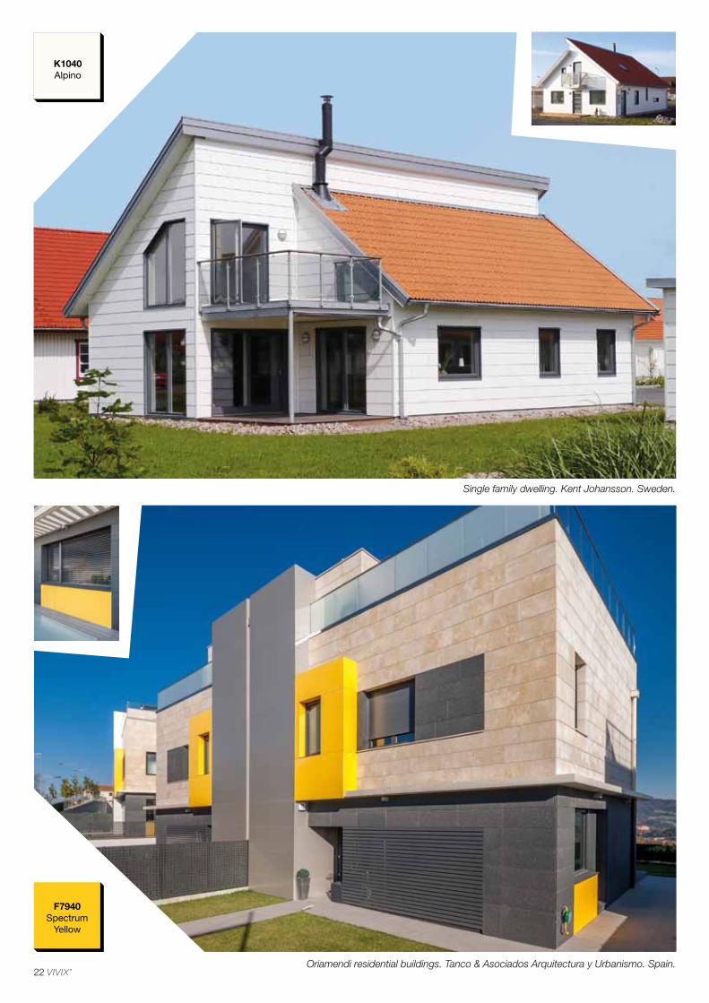
22
K1040Alpino
F7940Spectrum
Yellow
Oriamendi residential buildings. Tanco & Asociados Arquitectura y Urbanismo. Spain.
Single family dwelling. Kent Johansson. Sweden.
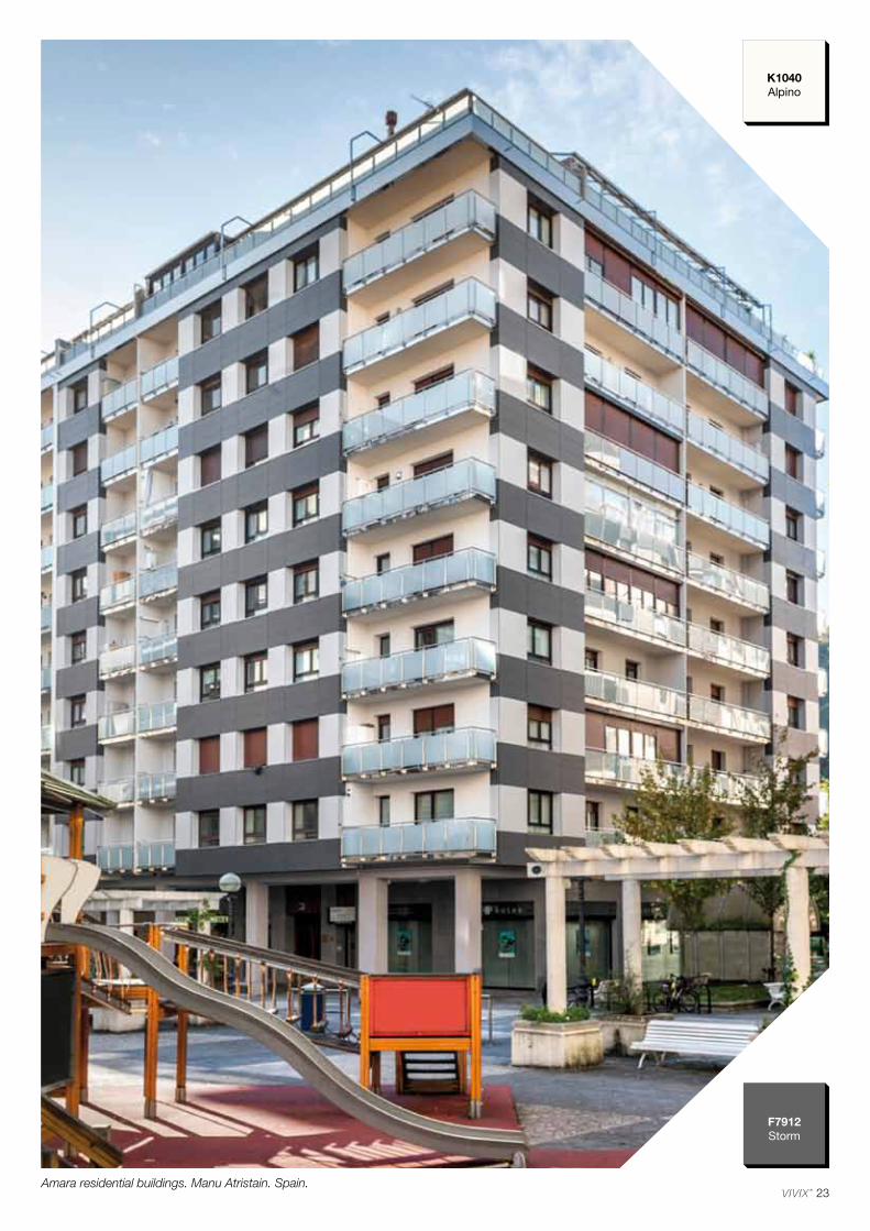
23
F7912Storm
K1040Alpino
Amara residential buildings. Manu Atristain. Spain.
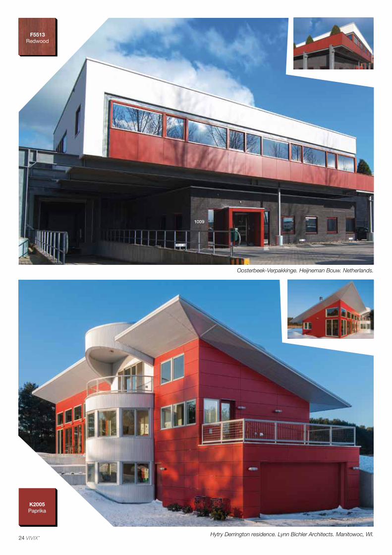
24
K2005Paprika
F5513Redwood
Hytry Derrington residence. Lynn Bichler Architects. Manitowoc, WI.
Oosterbeek-Verpakkinge. Heijneman Bouw. Netherlands.
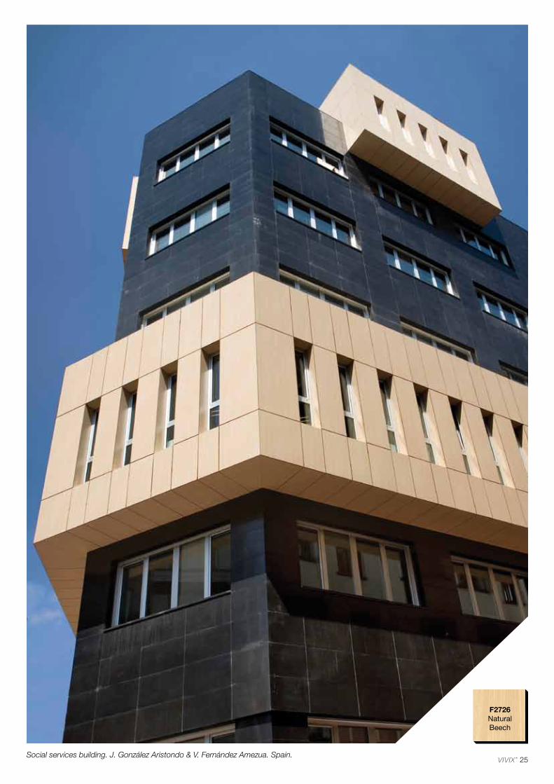
25
F2726NaturalBeech
Social services building. J. González Aristondo & V. Fernández Amezua. Spain.
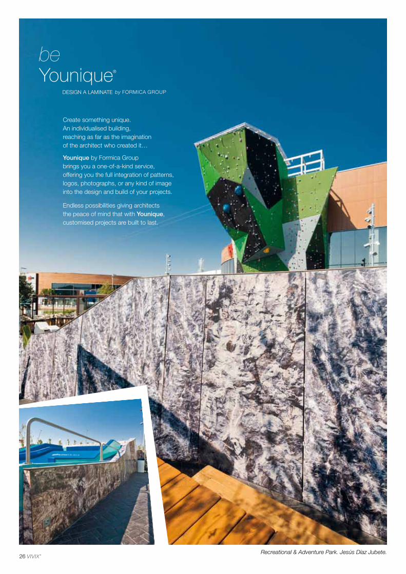
26Recreational & Adventure Park. Jesús Díaz Jubete.
Create something unique. An individualised building, reaching as far as the imagination of the architect who created it…
Younique by Formica Group brings you a one-of-a-kind service,offering you the full integration of patterns,logos, photographs, or any kind of imageinto the design and build of your projects.
Endless possibilities giving architectsthe peace of mind that with Younique, customised projects are built to last.
be

27Miribilla residential buildings. IMB Arquitectura.
Transformer Substation Beniferri-Valencia. Tomás Llavador Arquitectos+Ingenieros.
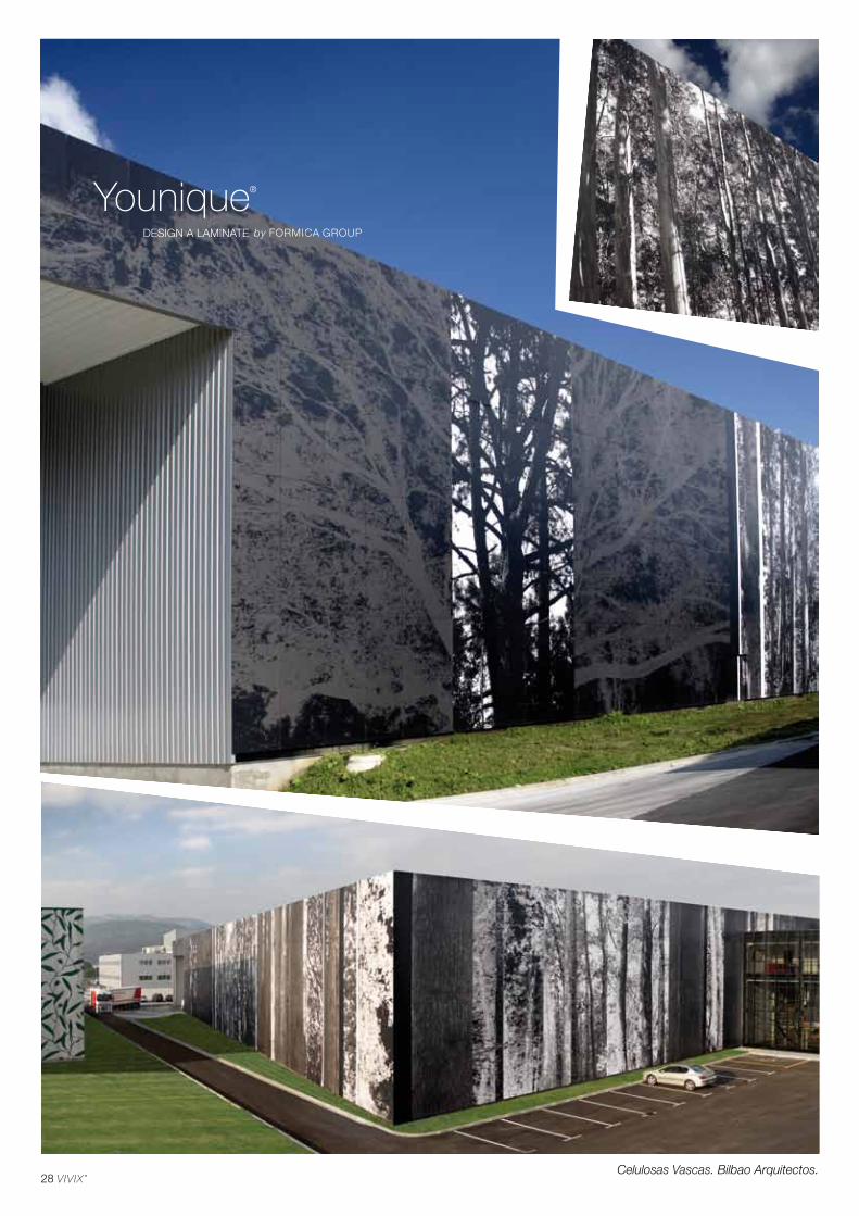
28Celulosas Vascas. Bilbao Arquitectos.
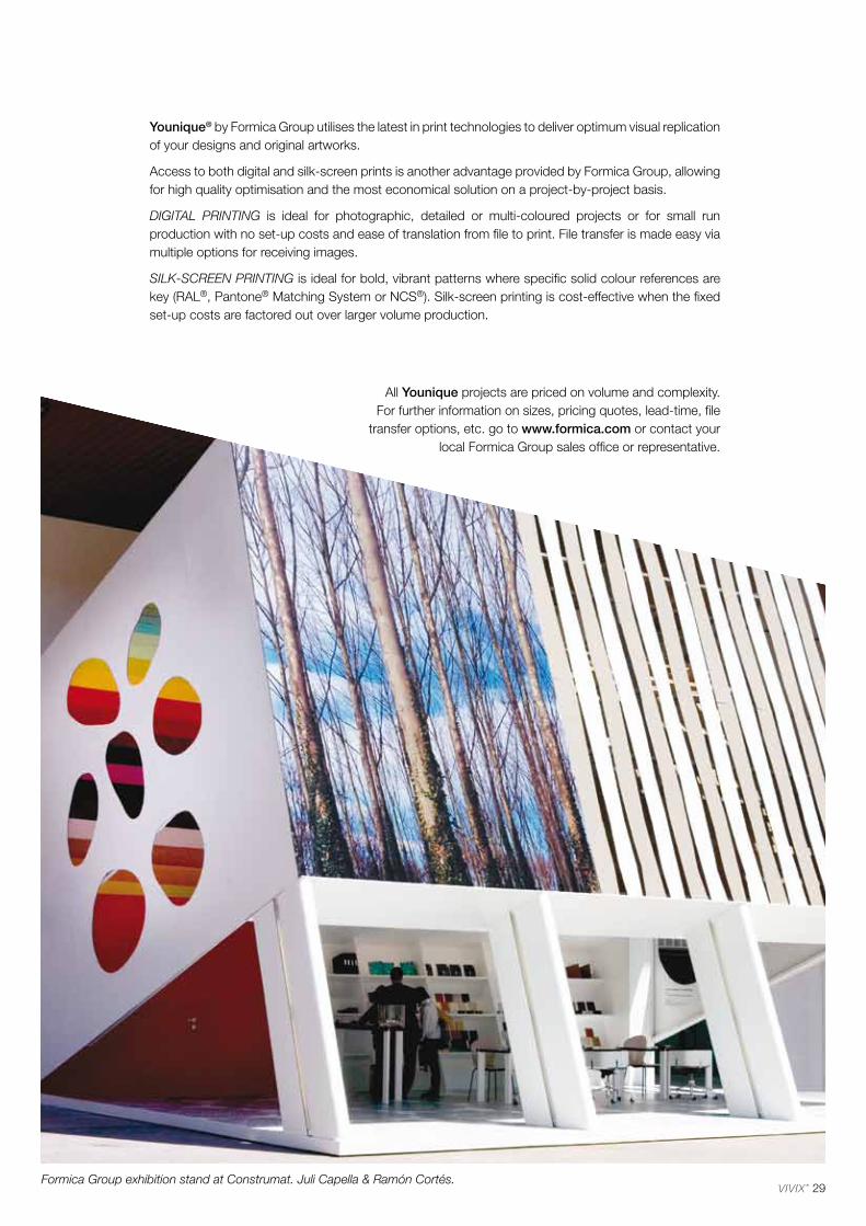
29Formica Group exhibition stand at Construmat. Juli Capella & Ramón Cortés.
Younique® by Formica Group utilises the latest in print technologies to deliver optimum visual replication of your designs and original artworks.
Access to both digital and silk-screen prints is another advantage provided by Formica Group, allowing for high quality optimisation and the most economical solution on a project-by-project basis.
DIGITAL PRINTING is ideal for photographic, detailed or multi-coloured projects or for small run production with no set-up costs and ease of translation from file to print. File transfer is made easy via multiple options for receiving images.
SILK-SCREEN PRINTING is ideal for bold, vibrant patterns where specific solid colour references are key (RAL®, Pantone® Matching System or NCS®). Silk-screen printing is cost-effective when the fixed set-up costs are factored out over larger volume production.
All Younique projects are priced on volume and complexity. For further information on sizes, pricing quotes, lead-time, file
transfer options, etc. go to www.formica.com or contact your local Formica Group sales office or representative.
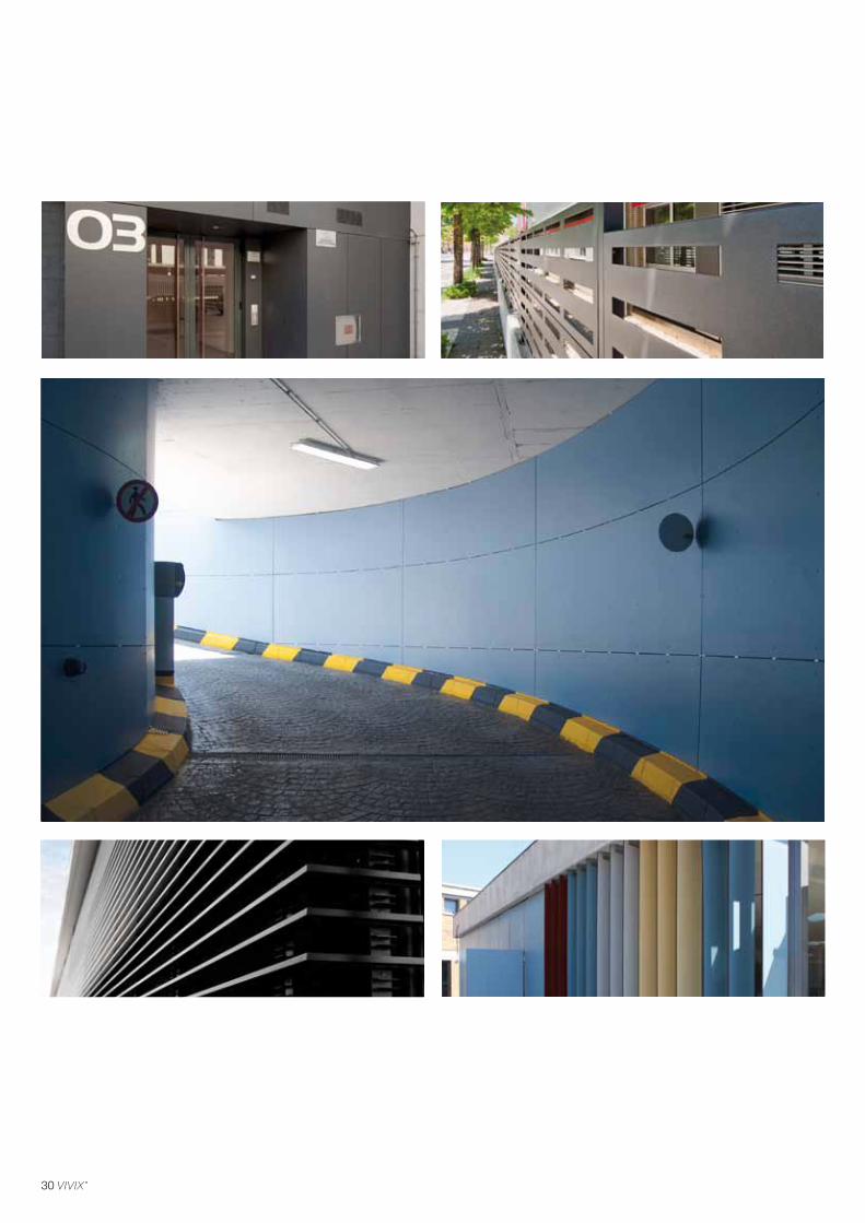
30
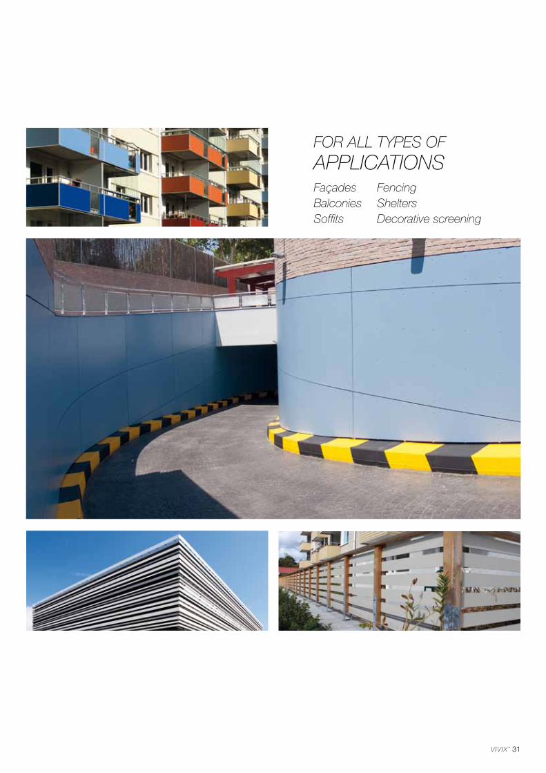
31
FaçadesBalconiesSoffits
FencingSheltersDecorative screening
FOR ALL TYPES OF APPLICATIONS
32

33
Plain colours, neutrals or bright tones, abstract designs inspired by nature. New, TRUE SCALE decors celebrate the natural beauty of wood in its true form and scale.
The VIVIX® panels range is developed in collaboration with architects and chromatography consultants to offer the most extensive range of decorative possibilities.
All colours in the VIVIX range have undergone rigorous testing to ensure UV stability in accordance
with EN 438-2 test methods 28 & 29 for colour fastness and weather resistance. Panels are tested
for severe use compliance.
CREATIVEbe
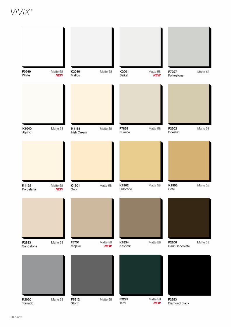
34
F2253Diamond Black
F0949 White
K1192 Porcelana
F8751Mojave
F2297 Terril
K2001Baikal
K1040 Alpino
Matte 58 K1181 Irish Cream
Matte 58
K1301 Gobi
Matte 58 K1902Eldorado
Matte 58
F2302Doeskin
Matte 58F7858Pumice
Matte 58
F7927Folkestone
Matte 58K2010 Malibu
Matte 58
K1834Kashmir
Matte 58
K2020Tornado
Matte 58
F2833 Sandstone
Matte 58
K1903Café
Matte 58
F2200Dark Chocolate
Matte 58
F7912Storm
Matte 58
Matte 58NEW
Matte 58NEW
Matte 58NEW
Matte 58NEW
Matte 58NEW
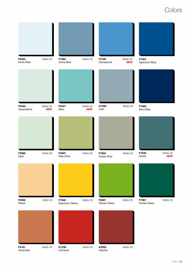
35
Colors
F7851Spectrum Blue
F7969Navy Blue
F5494Aquamarine
F5347Maui
F7846Grotto
F4168Campanula
F2966Opal
Matte 58 F7853Ocean Grey
Matte 58
F2288Peach
Matte 58
F5493Arctic Blue
Matte 58
K1998Oslo
Matte 58
F3007Pale Olive
Matte 58
F6901Vibrant Green
Matte 58 F7967 Hunter Green
Matte 58
F7884China Blue
Matte 58
F7940Spectrum Yellow
Matte 58
F4161Terracotta
Matte 58 K1238Carnaval
Matte 58 K2005Paprika
Matte 58
Matte 58NEW
Matte 58NEW
Matte 58NEW
Matte 58NEW

36
F6064Oxide Materia
F6067Steel Materia
F6074 Millsawn Slate
F6068Shadow Strié
Matte 58K3734Radon
Matte 58K3735 Krypton
Matte 58NEW
Matte 58NEW
Matte 58NEW
Matte 58NEW
Printed samples are shown at approximately 1:2 scale.
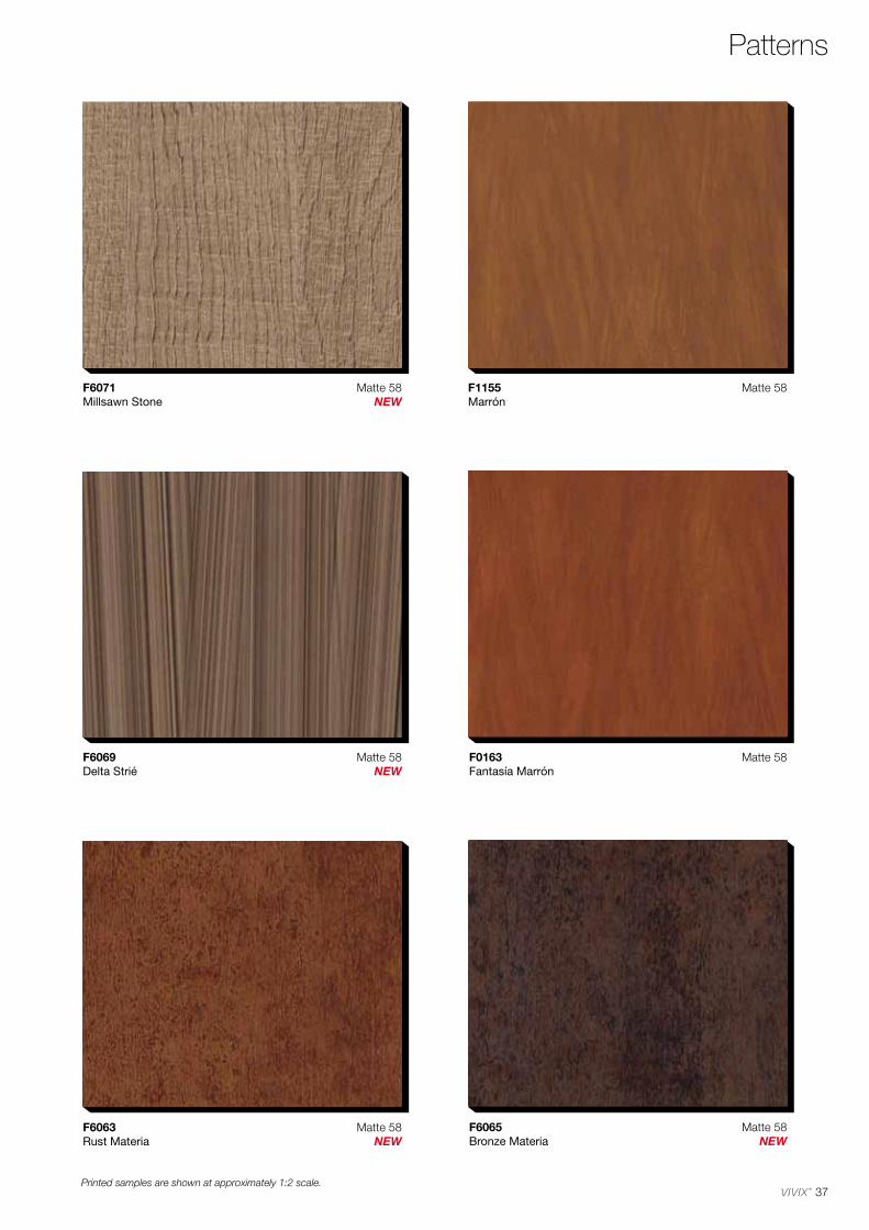
37
Patterns
F1155 Marrón
Matte 58
F0163Fantasía Marrón
Matte 58
F6065Bronze Materia
F6063Rust Materia
F6071Millsawn Stone
F6069Delta Strié
Matte 58NEW
Matte 58NEW
Matte 58NEW
Matte 58NEW
Printed samples are shown at approximately 1:2 scale.
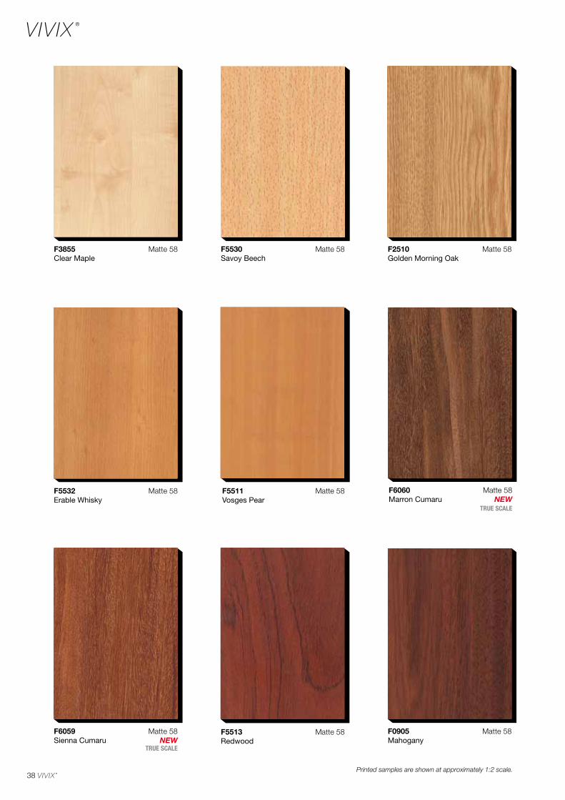
38
F0905Mahogany
F3855Clear Maple
Matte 58
F5532 Erable Whisky
Matte 58
F5530Savoy Beech
Matte 58
F5511Vosges Pear
Matte 58
F2510Golden Morning Oak
Matte 58
Matte 58F5513Redwood
Matte 58F6059Sienna Cumaru
F6060Marron Cumaru
TRUE SCALE
TRUE SCALE
Matte 58NEW
Matte 58NEW
Printed samples are shown at approximately 1:2 scale.
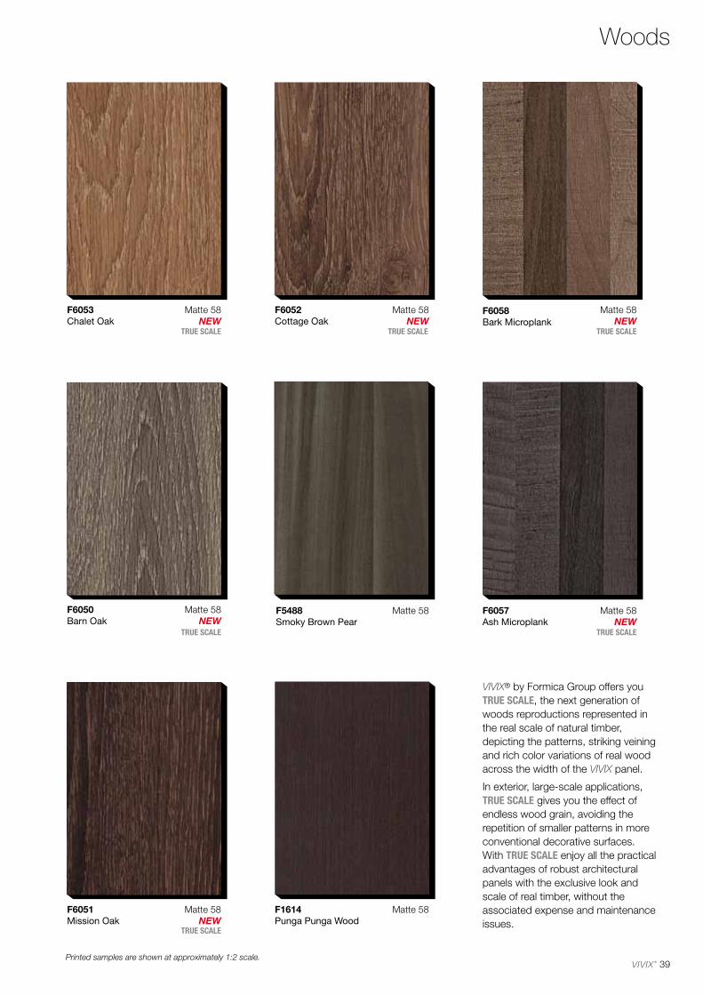
39
Woods
F6051Mission Oak
F5488Smoky Brown Pear
Matte 58
F6053Chalet Oak
F6058Bark Microplank
F1614Punga Punga Wood
Matte 58
F6050Barn Oak
F6057Ash Microplank
F6052 Cottage Oak
TRUE SCALE
TRUE SCALE TRUE SCALE TRUE SCALE
TRUE SCALE
TRUE SCALE
Matte 58NEW
Matte 58NEW
Matte 58NEW
Matte 58NEW
Matte 58NEW
Matte 58NEW
Printed samples are shown at approximately 1:2 scale.
VIVIX® by Formica Group offers you TRUE SCALE, the next generation of woods reproductions represented in the real scale of natural timber, depicting the patterns, striking veining and rich color variations of real wood across the width of the VIVIX panel.
In exterior, large-scale applications,TRUE SCALE gives you the effect of endless wood grain, avoiding the repetition of smaller patterns in more conventional decorative surfaces. With TRUE SCALE enjoy all the practical advantages of robust architectural panels with the exclusive look and scale of real timber, without the associated expense and maintenance issues.
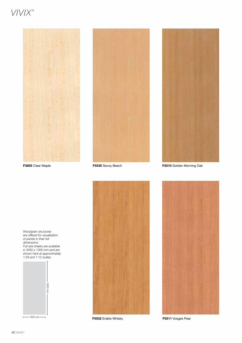
40
F5532 Erable Whisky F5511 Vosges Pear
F5530 Savoy BeechF3855 Clear Maple F2510 Golden Morning Oak
Woodgrain structures are offered for visualization of panels in their full dimensions.Full size sheets are available in 3050 x 1300 mm and are shown here at approximately 1:26 and 1:12 scales.
3050 mm
1300 mm
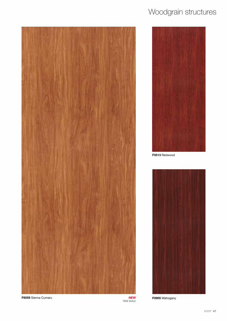
41
F5513 Redwood
F0905 MahoganyF6059 Sienna CumaruTRUE SCALE
Woodgrain structures
NEW
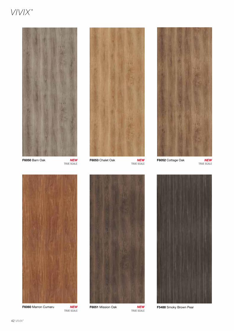
42
F5488 Smoky Brown Pear
F6052 Cottage OakF6050 Barn Oak F6053 Chalet Oak
F6051 Mission OakF6060 Marron Cumaru
TRUE SCALE TRUE SCALE
TRUE SCALETRUE SCALE
TRUE SCALENEW
NEW
NEW
NEW
NEW

43
F6058 Bark Microplank F1614 Punga Punga Wood
F6057 Ash MicroplankTRUE SCALE
TRUE SCALENEW
NEW
Woodgrain structures
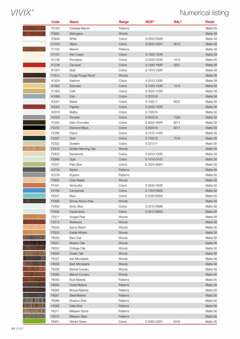
44
F0163 Fantasía Marrón Patterns Matte 58
F0905 Mahogany Woods Matte 58
F0949 White Colors S 0502-R50B Matte 58
K1040 Alpino Colors S 0502-G50Y 9010 Matte 58
F1155 Marrón Patterns Matte 58
K1181 Irish Cream Colors S 1005-Y50R Matte 58
K1192 Porcelana Colors S 0505-Y20R 1013 Matte 58
K1238 Carnaval Colors S 1580-Y90R 3001 Matte 58
K1301 Gobi Colors S 1010-Y30R Matte 58
F1614 Punga Punga Wood Woods Matte 58
K1834 Kashmir Colors S 5010-Y30R Matte 58
K1902 Eldorado Colors S 1020-Y20R 1014 Matte 58
K1903 Café Colors S 3020-Y20R Matte 58
K1998 Oslo Colors S 3020-B Matte 58
K2001 Baikal Colors S 1502-Y 9002 Matte 58
K2005 Paprika Colors S 4050-Y80R Matte 58
K2010 Malibu Colors S 1000-N Matte 58
K2020 Tornado Colors S 4500-N 7036 Matte 58
F2200 Dark Chocolate Colors S 8005-Y80R 8017 Matte 58
F2253 Diamond Black Colors S 9000-N 9011 Matte 58
F2288 Peach Colors S 1515-Y40R Matte 58
F2297 Terril Colors S 7502-B 7016 Matte 58
F2302 Doeskin Colors S 2010-Y Matte 58
F2510 Golden Morning Oak Woods Matte 58
F2833 Sandstone Colors S 2010-Y30R Matte 58
F2966 Opal Colors S 1010-G10Y Matte 58
F3007 Pale Olive Colors S 3020-G60Y Matte 58
K3734 Radon Patterns Matte 58
K3735 Krypton Patterns Matte 58
F3855 Clear Maple Woods Matte 58
F4161 Terracotta Colors S 3040-Y60R Matte 58
F4168 Campanula Colors S 1550-R80B Matte 58
F5347 Maui Colors S 2030-B30G Matte 58
F5488 Smoky Brown Pear Woods Matte 58
F5493 Arctic Blue Colors S 0510-R90B Matte 58
F5494 Aquamarine Colors S 0510-B90G Matte 58
F5511 Vosges Pear Woods Matte 58
F5513 Redwood Woods Matte 58
F5530 Savoy Beech Woods Matte 58
F5532 Erable Whisky Woods Matte 58
F6050 Barn Oak Woods Matte 58
F6051 Mission Oak Woods Matte 58
F6052 Cottage Oak Woods Matte 58
F6053 Chalet Oak Woods Matte 58
F6057 Ash Microplank Woods Matte 58
F6058 Bark Microplank Woods Matte 58
F6059 Sienna Cumaru Woods Matte 58
F6060 Marron Cumaru Woods Matte 58
F6063 Rust Materia Patterns Matte 58
F6064 Oxide Materia Patterns Matte 58
F6065 Bronze Materia Patterns Matte 58
F6067 Steel Materia Patterns Matte 58
F6068 Shadow Strié Patterns Matte 58
F6069 Delta Strié Patterns Matte 58
F6071 Millsawn Stone Patterns Matte 58
F6074 Millsawn Slate Patterns Matte 58
F6901 Vibrant Green Colors S 2060-G30Y 6018 Matte 58
Numerical listingCode Name Range NCS® RAL® Finish
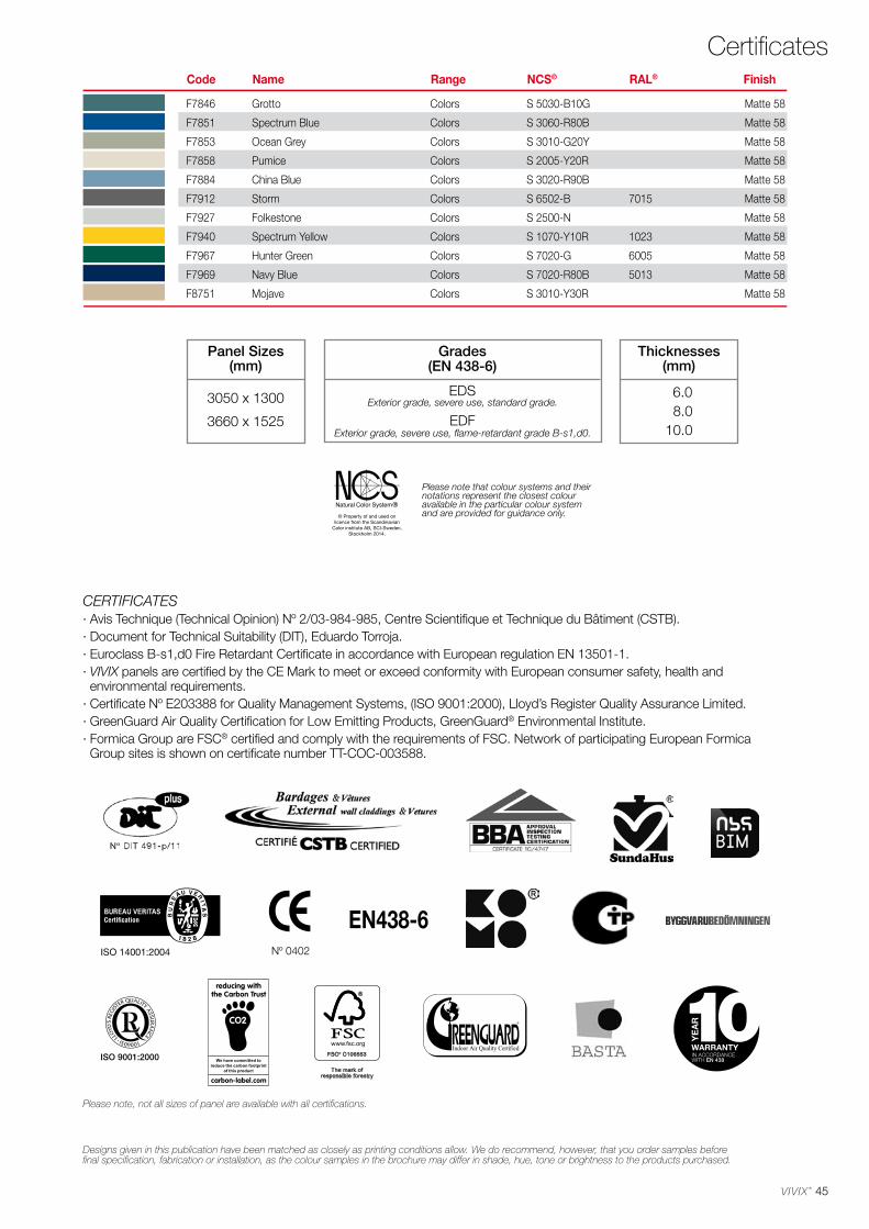
45
F7846 Grotto Colors S 5030-B10G Matte 58
F7851 Spectrum Blue Colors S 3060-R80B Matte 58
F7853 Ocean Grey Colors S 3010-G20Y Matte 58
F7858 Pumice Colors S 2005-Y20R Matte 58
F7884 China Blue Colors S 3020-R90B Matte 58
F7912 Storm Colors S 6502-B 7015 Matte 58
F7927 Folkestone Colors S 2500-N Matte 58
F7940 Spectrum Yellow Colors S 1070-Y10R 1023 Matte 58
F7967 Hunter Green Colors S 7020-G 6005 Matte 58
F7969 Navy Blue Colors S 7020-R80B 5013 Matte 58
F8751 Mojave Colors S 3010-Y30R Matte 58
Thicknesses(mm)
6.0 8.010.0
Panel Sizes(mm)
3050 x 1300
3660 x 1525
Grades(EN 438-6)
EDS
EDFExterior grade, severe use, standard grade.
Exterior grade, severe use, flame-retardant grade B-s1,d0.
Please note that colour systems and their notations represent the closest colour available in the particular colour system and are provided for guidance only.
CertificatesCode Name Range NCS® RAL® Finish
CERTIFICATES· Avis Technique (Technical Opinion) Nº 2/03-984-985, Centre Scientifique et Technique du Bâtiment (CSTB).· Document for Technical Suitability (DIT), Eduardo Torroja.· Euroclass B-s1,d0 Fire Retardant Certificate in accordance with European regulation EN 13501-1.· VIVIX panels are certified by the CE Mark to meet or exceed conformity with European consumer safety, health and environmental requirements.· Certificate Nº E203388 for Quality Management Systems, (ISO 9001:2000), Lloyd’s Register Quality Assurance Limited.· GreenGuard Air Quality Certification for Low Emitting Products, GreenGuard® Environmental Institute.· Formica Group are FSC® certified and comply with the requirements of FSC. Network of participating European Formica Group sites is shown on certificate number TT-COC-003588.
Designs given in this publication have been matched as closely as printing conditions allow. We do recommend, however, that you order samples before final specification, fabrication or installation, as the colour samples in the brochure may differ in shade, hue, tone or brightness to the products purchased.
Please note, not all sizes of panel are available with all certifications.
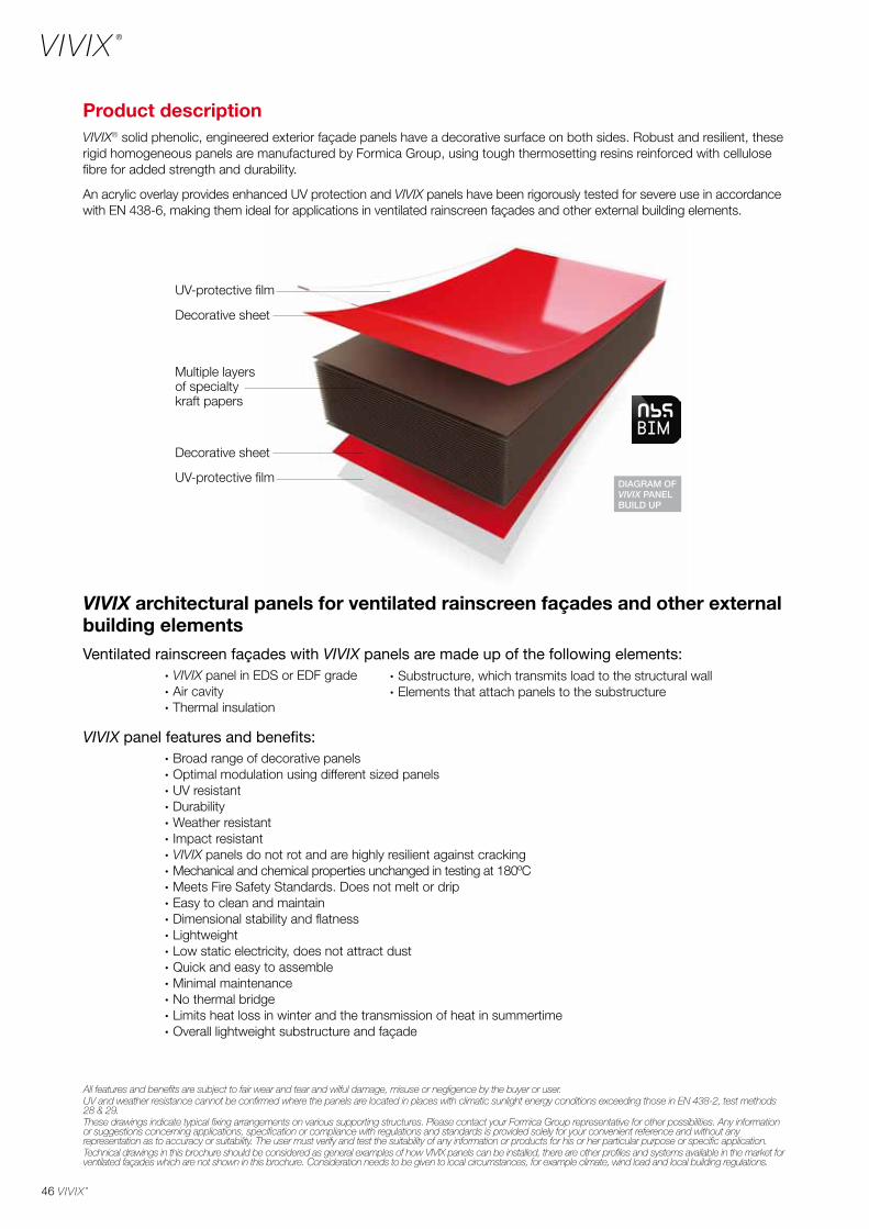
46
UV-protective film
UV-protective film
Multiple layers of specialty kraft papers
Decorative sheet
Decorative sheet
DIAGRAM OF VIVIX PANEL BUILD UP
Product description VIVIX® solid phenolic, engineered exterior façade panels have a decorative surface on both sides. Robust and resilient, these rigid homogeneous panels are manufactured by Formica Group, using tough thermosetting resins reinforced with cellulose fibre for added strength and durability.
An acrylic overlay provides enhanced UV protection and VIVIX panels have been rigorously tested for severe use in accordance with EN 438-6, making them ideal for applications in ventilated rainscreen façades and other external building elements.
All features and benefits are subject to fair wear and tear and wilful damage, misuse or negligence by the buyer or user.UV and weather resistance cannot be confirmed where the panels are located in places with climatic sunlight energy conditions exceeding those in EN 438-2, test methods 28 & 29.These drawings indicate typical fixing arrangements on various supporting structures. Please contact your Formica Group representative for other possibilities. Any information or suggestions concerning applications, specification or compliance with regulations and standards is provided solely for your convenient reference and without any representation as to accuracy or suitability. The user must verify and test the suitability of any information or products for his or her particular purpose or specific application.Technical drawings in this brochure should be considered as general examples of how VIVIX panels can be installed, there are other profiles and systems available in the market for ventilated façades which are not shown in this brochure. Consideration needs to be given to local circumstances, for example climate, wind load and local building regulations.
VIVIX architectural panels for ventilated rainscreen façades and other external building elementsVentilated rainscreen façades with VIVIX panels are made up of the following elements: · VIVIX panel in EDS or EDF grade · Air cavity · Thermal insulation
VIVIX panel features and benefits: · Broad range of decorative panels · Optimal modulation using different sized panels · UV resistant · Durability · Weather resistant · Impact resistant · VIVIX panels do not rot and are highly resilient against cracking · Mechanical and chemical properties unchanged in testing at 180ºC · Meets Fire Safety Standards. Does not melt or drip · Easy to clean and maintain · Dimensional stability and flatness · Lightweight · Low static electricity, does not attract dust · Quick and easy to assemble · Minimal maintenance · No thermal bridge · Limits heat loss in winter and the transmission of heat in summertime · Overall lightweight substructure and façade
· Substructure, which transmits load to the structural wall· Elements that attach panels to the substructure
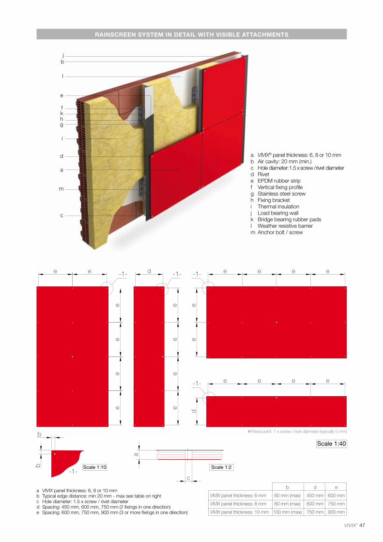
47
bj
d
i
l
a
m
c
f
hk
g
e
RAINSCREEN SYSTEM IN DETAIL WITH VISIBLE ATTACHMENTS
a VIVIX® panel thickness: 6, 8 or 10 mmb Air cavity: 20 mm (min.)c Hole diameter: 1.5 x screw / rivet diameterd Rivete EPDM rubber stripf Vertical fixing profileg Stainless steel screwh Fixing bracketi Thermal insulationj Load bearing wallk Bridge bearing rubber padsl Weather resistive barrierm Anchor bolt / screw
Scale 1:40
Scale 1:10
a VIVIX panel thickness: 6, 8 or 10 mmb Typical edge distance: min 20 mm - max see table on rightc Hole diameter: 1.5 x screw / rivet diameterd Spacing: 450 mm, 600 mm, 750 mm (2 fixings in one direction)e Spacing: 600 mm, 750 mm, 900 mm (3 or more fixings in one direction)
b d e
VIVIX panel thickness: 6 mm 60 mm (max) 450 mm 600 mm
VIVIX panel thickness: 8 mm 80 mm (max) 600 mm 750 mm
VIVIX panel thickness: 10 mm 100 mm (max) 750 mm 900 mm
¤ Fixed point: 1 x screw / rivet diameter (typically 5 mm)
Scale 1:2
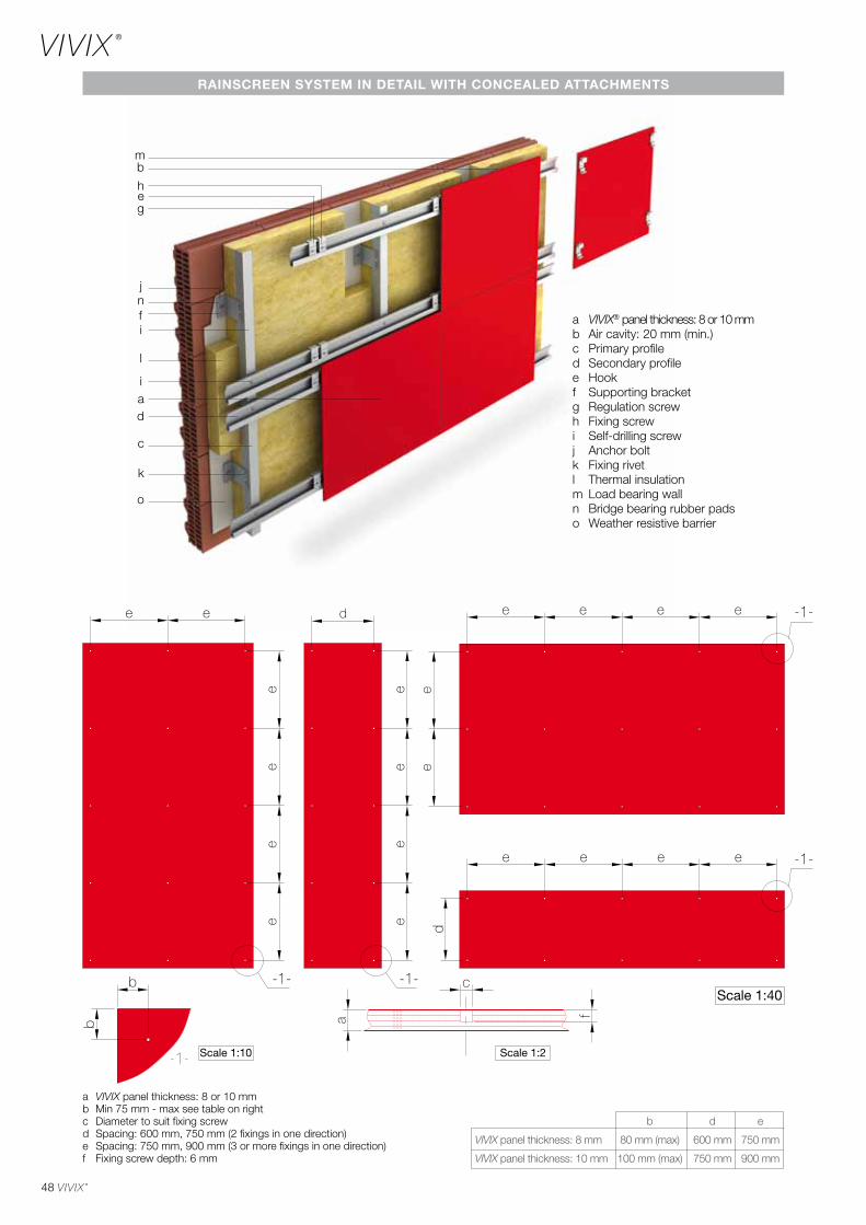
48
mb
l
i
dai
c
o
k
j
fn
heg
RAINSCREEN SYSTEM IN DETAIL WITH CONCEALED ATTACHMENTS
a VIVIX® panel thickness: 8 or 10 mmb Air cavity: 20 mm (min.)c Primary profiled Secondary profilee Hookf Supporting bracketg Regulation screwh Fixing screwi Self-drilling screwj Anchor boltk Fixing rivetl Thermal insulationm Load bearing walln Bridge bearing rubber padso Weather resistive barrier
Scale 1:10
Scale 1:40
a VIVIX panel thickness: 8 or 10 mmb Min 75 mm - max see table on rightc Diameter to suit fixing screwd Spacing: 600 mm, 750 mm (2 fixings in one direction)e Spacing: 750 mm, 900 mm (3 or more fixings in one direction)f Fixing screw depth: 6 mm
b d e
VIVIX panel thickness: 8 mm 80 mm (max) 600 mm 750 mm
VIVIX panel thickness: 10 mm 100 mm (max) 750 mm 900 mm
Scale 1:2
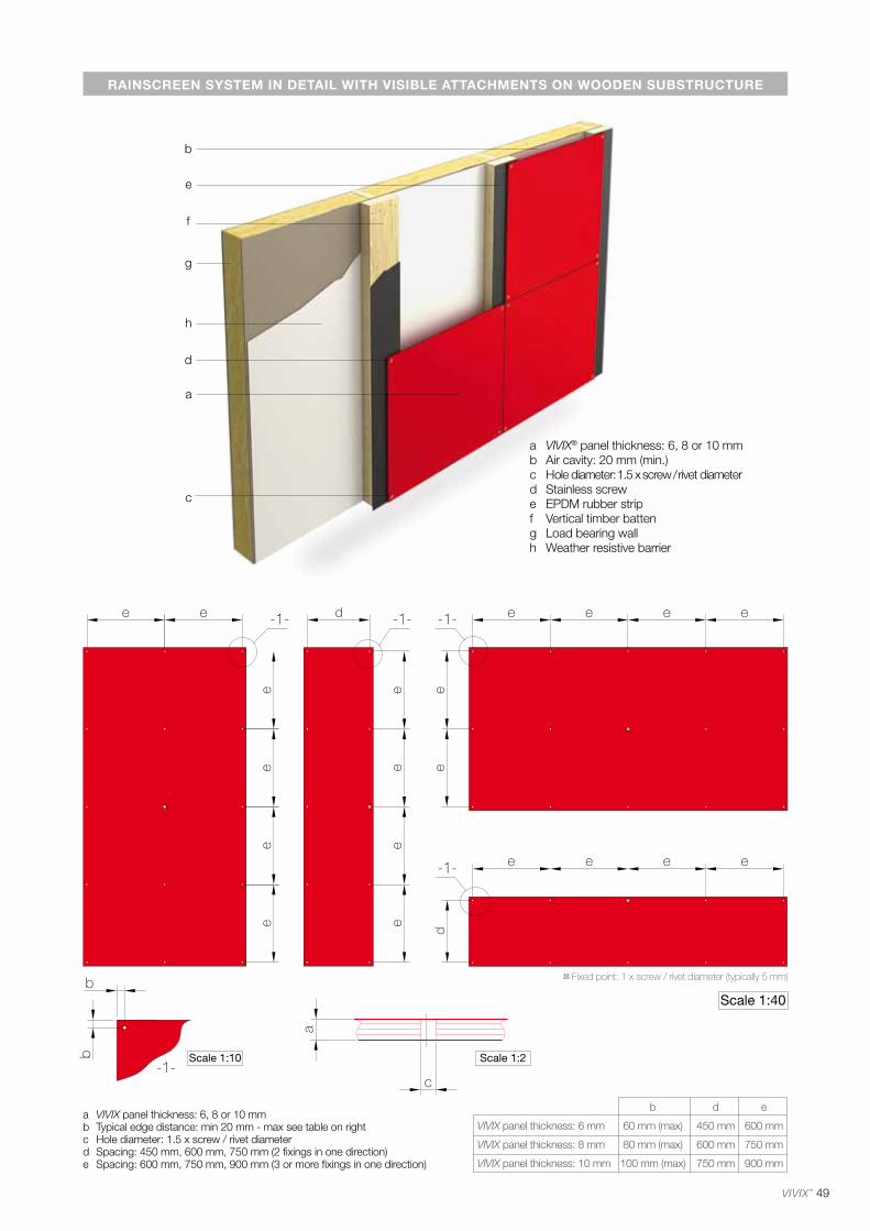
49
b
d
h
a
c
f
g
e
RAINSCREEN SYSTEM IN DETAIL WITH VISIBLE ATTACHMENTS ON WOODEN SUBSTRUCTURE
a VIVIX® panel thickness: 6, 8 or 10 mmb Air cavity: 20 mm (min.)c Hole diameter: 1.5 x screw / rivet diameterd Stainless screwe EPDM rubber stripf Vertical timber batteng Load bearing wallh Weather resistive barrier
¤ Fixed point: 1 x screw / rivet diameter (typically 5 mm)
Scale 1:40
Scale 1:2Scale 1:10
a VIVIX panel thickness: 6, 8 or 10 mmb Typical edge distance: min 20 mm - max see table on rightc Hole diameter: 1.5 x screw / rivet diameterd Spacing: 450 mm, 600 mm, 750 mm (2 fixings in one direction)e Spacing: 600 mm, 750 mm, 900 mm (3 or more fixings in one direction)
b d e
VIVIX panel thickness: 6 mm 60 mm (max) 450 mm 600 mm
VIVIX panel thickness: 8 mm 80 mm (max) 600 mm 750 mm
VIVIX panel thickness: 10 mm 100 mm (max) 750 mm 900 mm
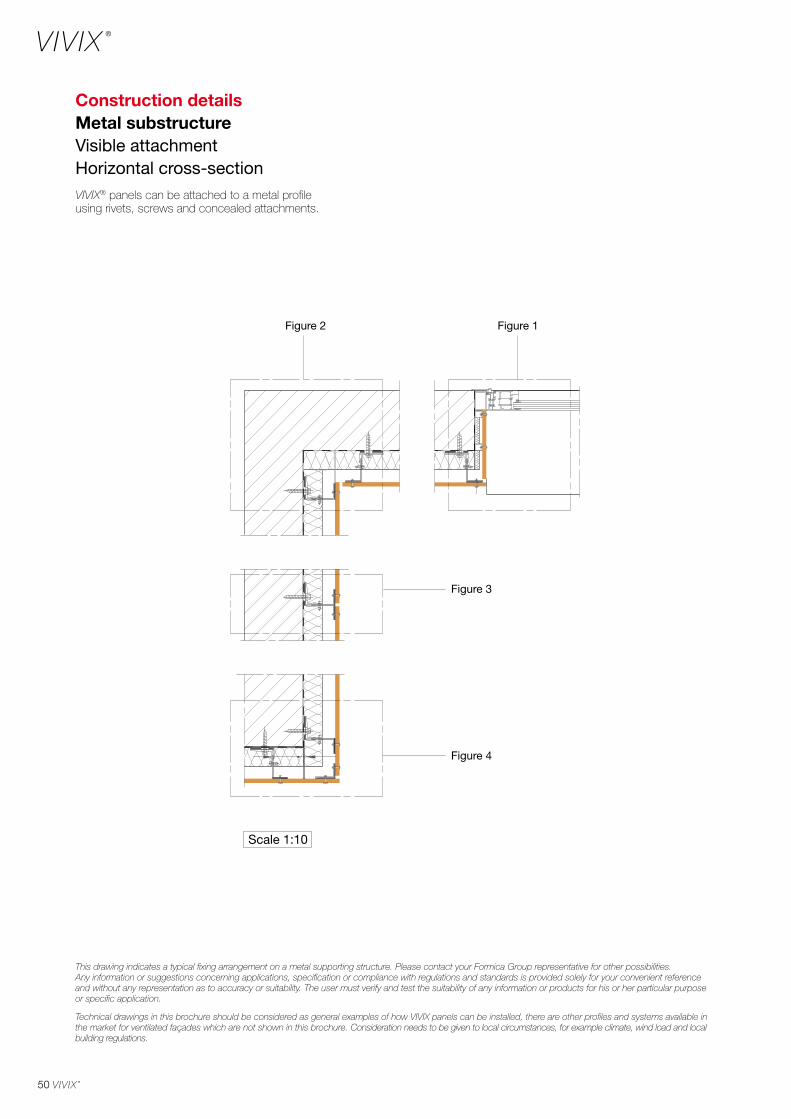
50
Construction detailsMetal substructureVisible attachmentHorizontal cross-sectionVIVIX® panels can be attached to a metal profile using rivets, screws and concealed attachments.
Figure 2 Figure 1
Figure 3
Figure 4
Scale 1:10
This drawing indicates a typical fixing arrangement on a metal supporting structure. Please contact your Formica Group representative for other possibilities. Any information or suggestions concerning applications, specification or compliance with regulations and standards is provided solely for your convenient reference and without any representation as to accuracy or suitability. The user must verify and test the suitability of any information or products for his or her particular purpose or specific application.
Technical drawings in this brochure should be considered as general examples of how VIVIX panels can be installed, there are other profiles and systems available in the market for ventilated façades which are not shown in this brochure. Consideration needs to be given to local circumstances, for example climate, wind load and local building regulations.
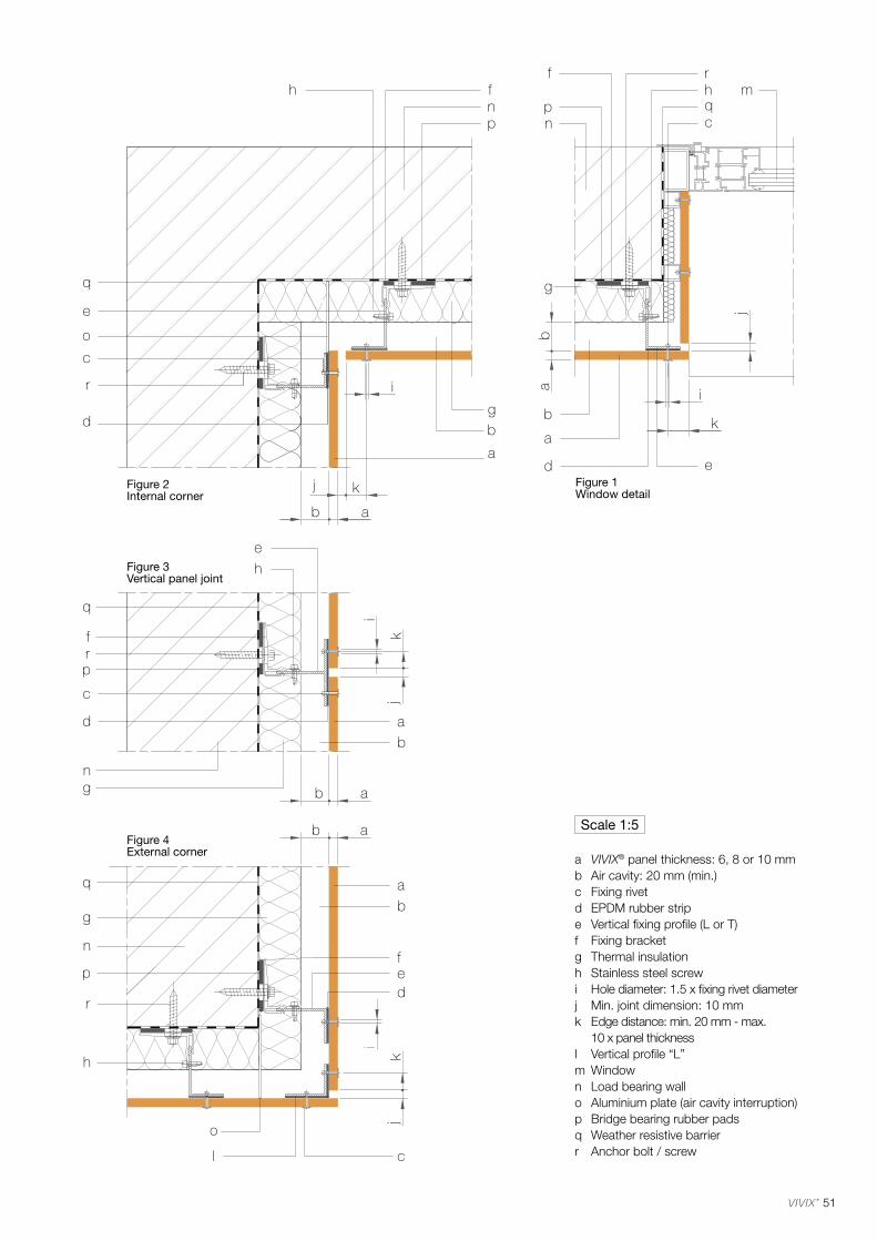
51
a VIVIX® panel thickness: 6, 8 or 10 mmb Air cavity: 20 mm (min.)c Fixing rivetd EPDM rubber stripe Vertical fixing profile (L or T)f Fixing bracketg Thermal insulationh Stainless steel screwi Hole diameter: 1.5 x fixing rivet diameterj Min. joint dimension: 10 mmk Edge distance: min. 20 mm - max. 10 x panel thicknessl Vertical profile “L”m Windown Load bearing wallo Aluminium plate (air cavity interruption)p Bridge bearing rubber padsq Weather resistive barrierr Anchor bolt / screw
Scale 1:5
Figure 2Internal corner
Figure 1Window detail
Figure 3Vertical panel joint
Figure 4External corner
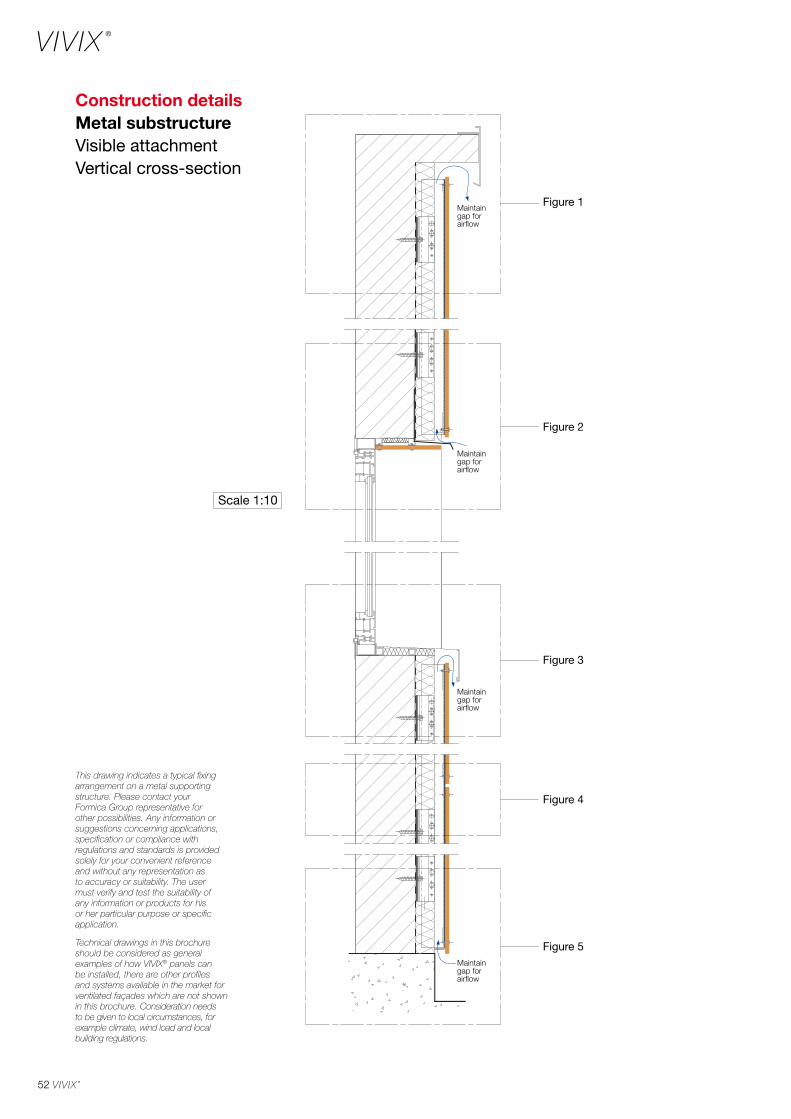
52
This drawing indicates a typical fixing arrangement on a metal supporting structure. Please contact your Formica Group representative for other possibilities. Any information or suggestions concerning applications, specification or compliance with regulations and standards is provided solely for your convenient reference and without any representation as to accuracy or suitability. The user must verify and test the suitability of any information or products for his or her particular purpose or specific application.
Technical drawings in this brochure should be considered as general examples of how VIVIX® panels can be installed, there are other profiles and systems available in the market for ventilated façades which are not shown in this brochure. Consideration needs to be given to local circumstances, for example climate, wind load and local building regulations.
Figure 4
Figure 5
Figure 3
Figure 2
Figure 1
Scale 1:10
Maintain gap for airflow
Maintain gap for airflow
Maintain gap for airflow
Maintain gap for airflow
Construction detailsMetal substructureVisible attachmentVertical cross-section
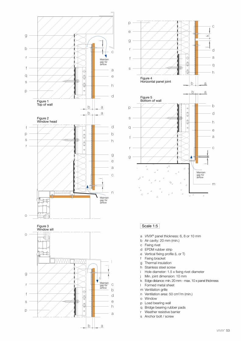
53
Figure 2Window head
Figure 1Top of wall
Figure 4Horizontal panel joint
Figure 5Bottom of wall
Figure 3Window sill
a VIVIX® panel thickness: 6, 8 or 10 mmb Air cavity: 20 mm (min.)c Fixing rivetd EPDM rubber stripe Vertical fixing profile (L or T)f Fixing bracketg Thermal insulationh Stainless steel screwi Hole diameter: 1.5 x fixing rivet diameterj Min. joint dimension: 10 mmk Edge distance: min. 20 mm - max. 10 x panel thicknessl Formed metal sheetm Ventilation grillen Ventilation area: 50 cm2/m (min.)o Windowp Load bearing wallq Bridge bearing rubber padsr Weather resistive barriers Anchor bolt / screw
Scale 1:5
Maintain gap for airflow
Maintain gap for airflow
Maintain gap for airflow
Maintain gap for airflow
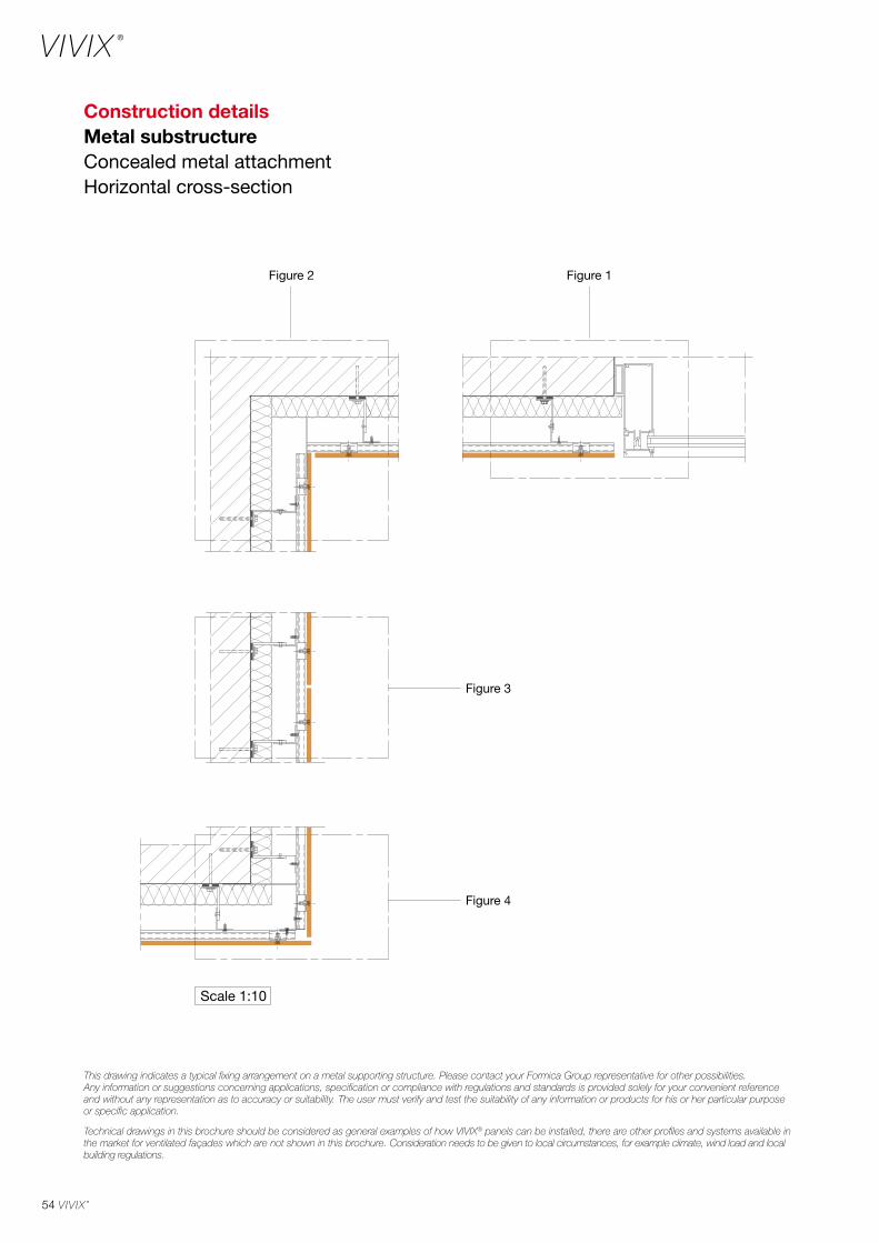
54
Construction detailsMetal substructureConcealed metal attachmentHorizontal cross-section
Figure 2 Figure 1
Figure 3
Figure 4
Scale 1:10
This drawing indicates a typical fixing arrangement on a metal supporting structure. Please contact your Formica Group representative for other possibilities. Any information or suggestions concerning applications, specification or compliance with regulations and standards is provided solely for your convenient reference and without any representation as to accuracy or suitability. The user must verify and test the suitability of any information or products for his or her particular purpose or specific application.
Technical drawings in this brochure should be considered as general examples of how VIVIX® panels can be installed, there are other profiles and systems available in the market for ventilated façades which are not shown in this brochure. Consideration needs to be given to local circumstances, for example climate, wind load and local building regulations.
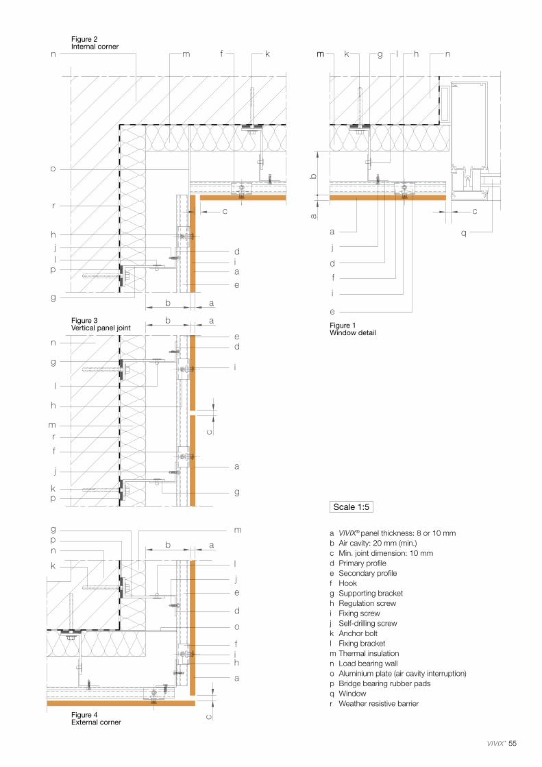
55
Figure 2Internal corner
Figure 1Window detail
Figure 3Vertical panel joint
Figure 4External corner
a VIVIX® panel thickness: 8 or 10 mmb Air cavity: 20 mm (min.)c Min. joint dimension: 10 mmd Primary profilee Secondary profilef Hookg Supporting bracketh Regulation screwi Fixing screwj Self-drilling screwk Anchor boltl Fixing bracketm Thermal insulationn Load bearing wallo Aluminium plate (air cavity interruption)p Bridge bearing rubber padsq Windowr Weather resistive barrier
Scale 1:5
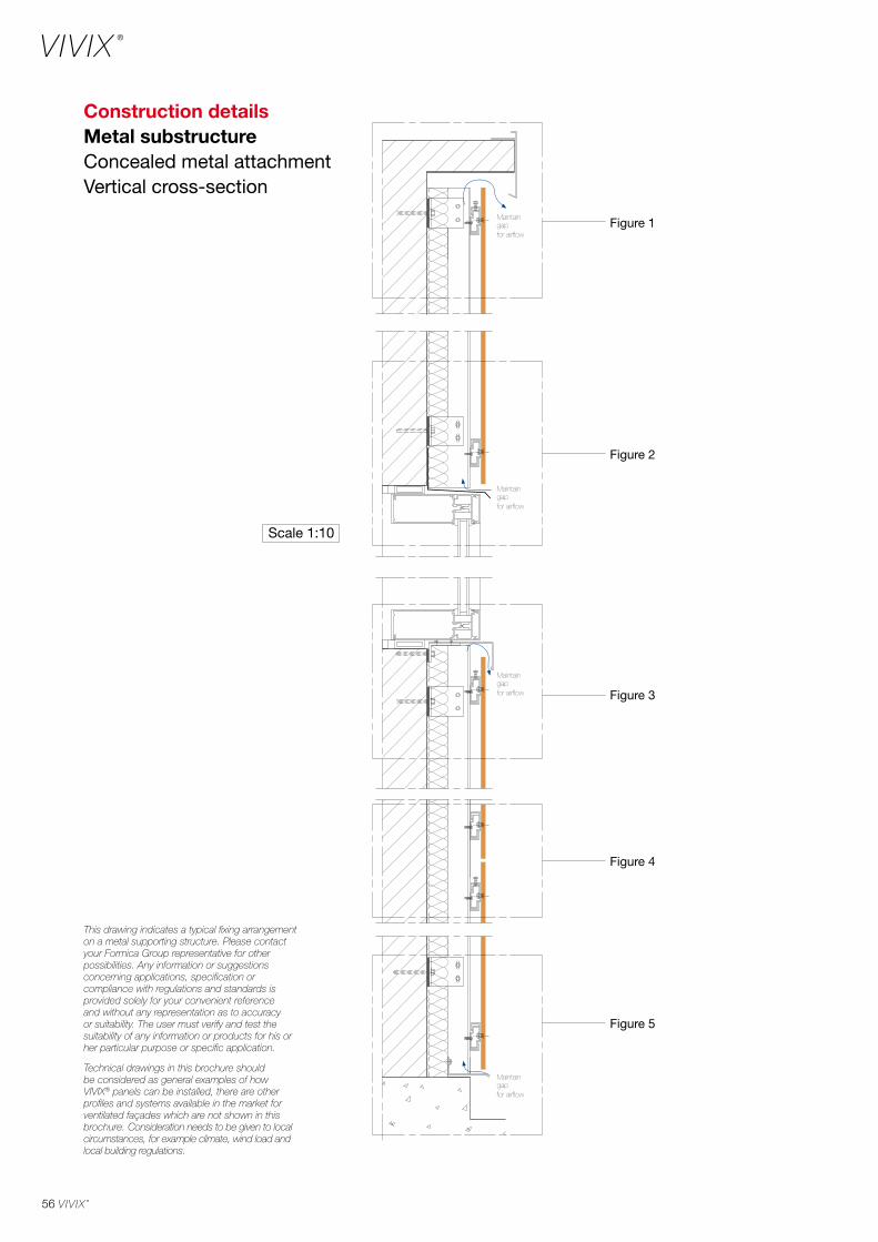
56
Construction detailsMetal substructureConcealed metal attachmentVertical cross-section
This drawing indicates a typical fixing arrangement on a metal supporting structure. Please contact your Formica Group representative for other possibilities. Any information or suggestions concerning applications, specification or compliance with regulations and standards is provided solely for your convenient reference and without any representation as to accuracy or suitability. The user must verify and test the suitability of any information or products for his or her particular purpose or specific application.
Technical drawings in this brochure should be considered as general examples of how VIVIX® panels can be installed, there are other profiles and systems available in the market for ventilated façades which are not shown in this brochure. Consideration needs to be given to local circumstances, for example climate, wind load and local building regulations.
Scale 1:10
Figure 4
Figure 5
Figure 3
Figure 2
Figure 1
Maintain gapfor airflow
Maintain gapfor airflow
Maintain gapfor airflow
Maintain gapfor airflow
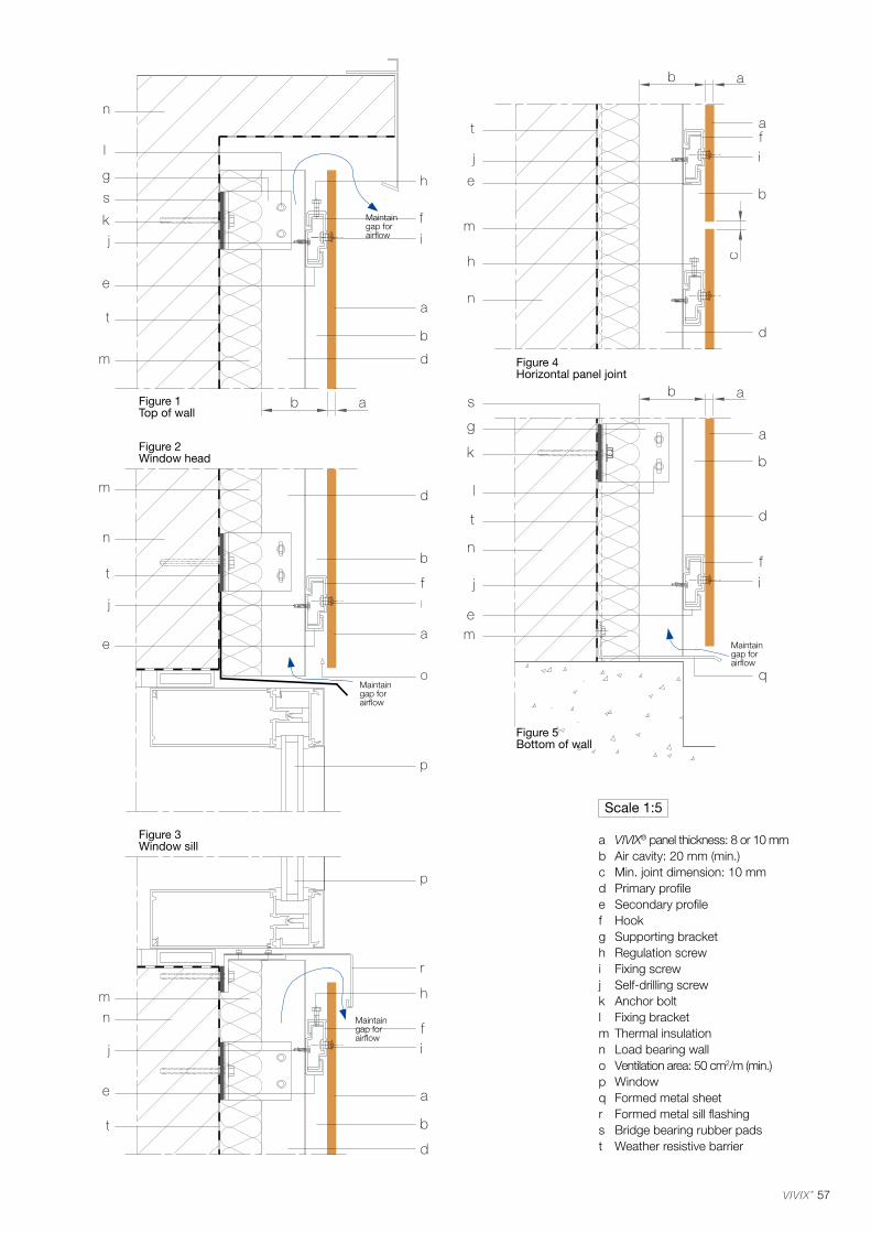
57
Maintain gap for airflow
Figure 2Window head
Figure 1Top of wall
Figure 4Horizontal panel joint
Figure 5Bottom of wall
Figure 3Window sill
Maintain gap for airflow
Maintain gap for airflow
Maintain gap for airflow
a VIVIX® panel thickness: 8 or 10 mmb Air cavity: 20 mm (min.)c Min. joint dimension: 10 mmd Primary profilee Secondary profilef Hookg Supporting bracketh Regulation screwi Fixing screwj Self-drilling screwk Anchor boltl Fixing bracketm Thermal insulationn Load bearing wallo Ventilation area: 50 cm2/m (min.)p Windowq Formed metal sheetr Formed metal sill flashings Bridge bearing rubber padst Weather resistive barrier
Scale 1:5
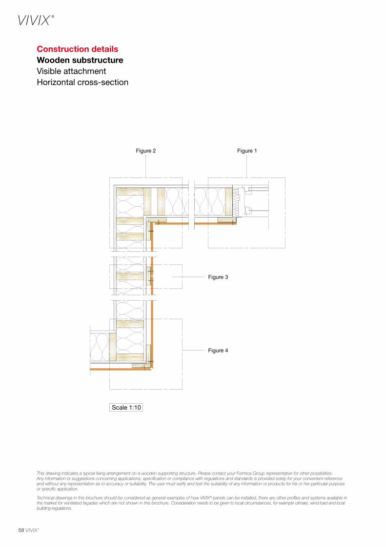
58
Construction detailsWooden substructureVisible attachmentHorizontal cross-section
This drawing indicates a typical fixing arrangement on a wooden supporting structure. Please contact your Formica Group representative for other possibilities. Any information or suggestions concerning applications, specification or compliance with regulations and standards is provided solely for your convenient reference and without any representation as to accuracy or suitability. The user must verify and test the suitability of any information or products for his or her particular purpose or specific application.
Technical drawings in this brochure should be considered as general examples of how VIVIX® panels can be installed, there are other profiles and systems available in the market for ventilated façades which are not shown in this brochure. Consideration needs to be given to local circumstances, for example climate, wind load and local building regulations.
Figure 2 Figure 1
Figure 3
Figure 4
Scale 1:10
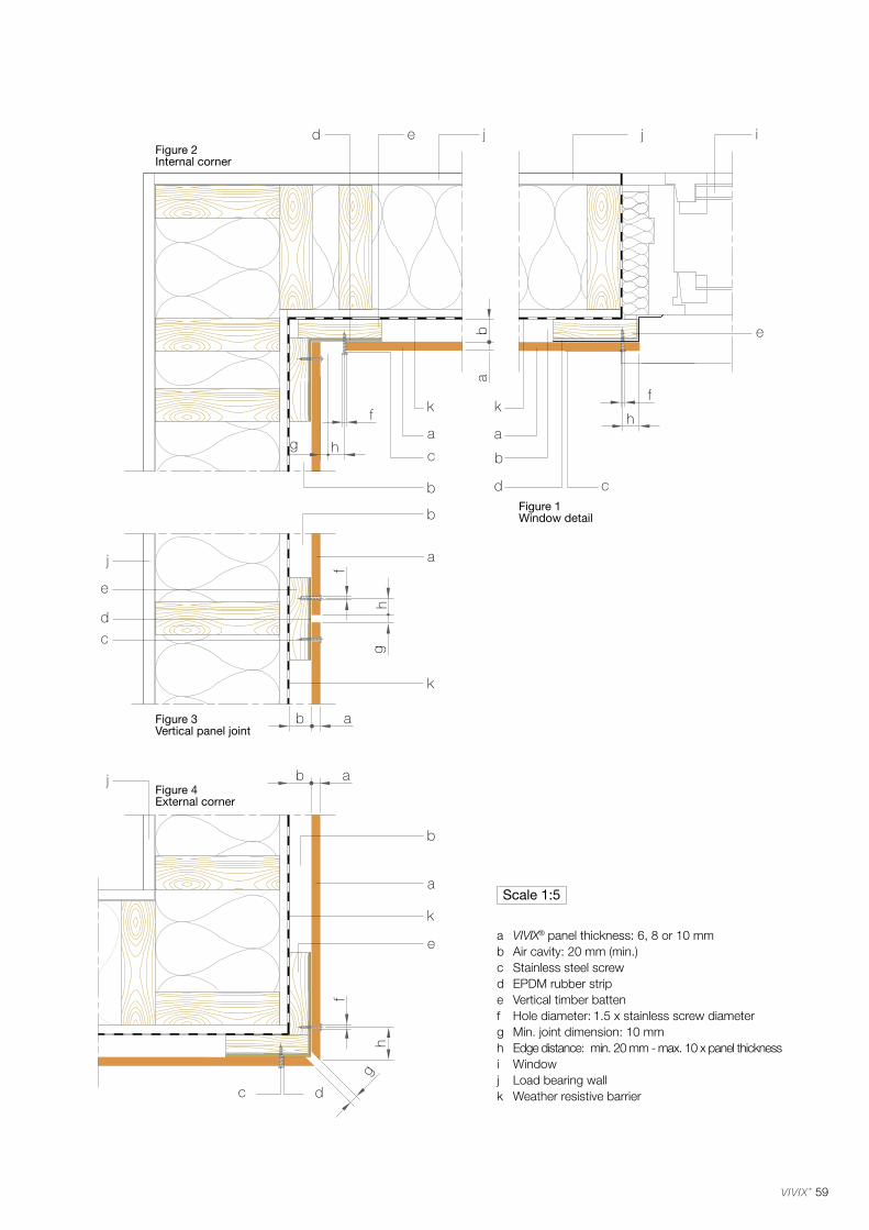
59
a VIVIX® panel thickness: 6, 8 or 10 mmb Air cavity: 20 mm (min.)c Stainless steel screwd EPDM rubber stripe Vertical timber battenf Hole diameter: 1.5 x stainless screw diameterg Min. joint dimension: 10 mmh Edge distance: min. 20 mm - max. 10 x panel thicknessi Windowj Load bearing wallk Weather resistive barrier
Scale 1:5
Figure 2Internal corner
Figure 1Window detail
Figure 3Vertical panel joint
Figure 4External corner

60
Construction detailsWooden substructureVisible attachmentVertical cross-section
This drawing indicates a typical fixing arrangement on a wooden supporting structure. Please contact your Formica Group representative for other possibilities. Any information or suggestions concerning applications, specification or compliance with regulations and standards is provided solely for your convenient reference and without any representation as to accuracy or suitability. The user must verify and test the suitability of any information or products for his or her particular purpose or specific application.
Technical drawings in this brochure should be considered as general examples of how VIVIX® panels can be installed, there are other profiles and systems available in the market for ventilated façades which are not shown in this brochure. Consideration needs to be given to local circumstances, for example climate, wind load and local building regulations.
Scale 1:10
Figure 4
Figure 5
Figure 3
Figure 2
Figure 1
Maintain gapfor airflow
Maintain gapfor airflow
Maintain gapfor airflow
Maintain gapfor airflow
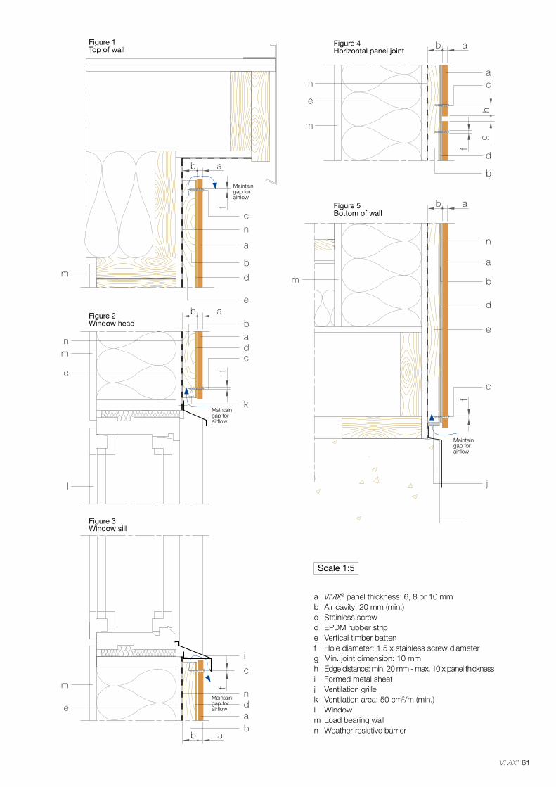
61
a VIVIX® panel thickness: 6, 8 or 10 mmb Air cavity: 20 mm (min.)c Stainless screwd EPDM rubber stripe Vertical timber battenf Hole diameter: 1.5 x stainless screw diameterg Min. joint dimension: 10 mmh Edge distance: min. 20 mm - max. 10 x panel thicknessi Formed metal sheetj Ventilation grillek Ventilation area: 50 cm2/m (min.)l Windowm Load bearing walln Weather resistive barrier
Scale 1:5
Figure 2Window head
Figure 1Top of wall
Figure 4Horizontal panel joint
Figure 5Bottom of wall
Figure 3Window sill
Maintain gap for airflow
Maintain gap for airflow
Maintain gap for airflow
Maintain gap for airflow
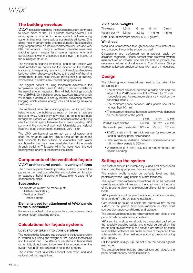
62
The building envelopeVIVIX® installations utilising the rainscreen system contribute to seven areas of the LEED credits across several LEED rating systems. In order to be recognized by these rating systems, they must have various sustainable attributes. One of the most important is the system’s durability. Because of its long lifespan, there are no refurbishments required and very little maintenance. Using a ventilated insulated rainscreen cladding system means less material replacements and considerably lower maintenance costs over the lifetime of the building or structure.
The rainscreen cladding system is used in conjunction with VIVIX architectural panels for the exterior of the building enclosure. It is especially resistant to both mold and moisture build-up, which directly contributes to the quality of the living environment. It also helps insulate the exterior of a building, which helps to address any thermal bridging issues.
The biggest benefit of using rainscreen systems is the temperature regulation and its ability to accommodate for the use of exterior insulation. This will help buildings comply with ASHRAE 90.1 building codes (www.ashrae.org) which will require a continuous energy barrier, preventing thermal bridging which causes energy loss and building envelope inefficiency.
The ventilated rainscreen cladding system, on its own, also helps to cool the building as most of the sun’s rays are reflected away. Additionally, any heat that does in fact pass through the exterior wall dissipates because of the ventilating effect of the air space between the exterior cladding VIVIX panel and the structural wall itself. Ultimately, any residual heat that does penetrate the building is very minor.
The VIVIX architectural panels act as a rainscreen and keep the structural wall dry. This is because the air space that connects to the outside air evacuates both water and humidity that may have penetrated behind the panels through the joints. This water will in fact never reach the load bearing walls or any of the thermal insulation.
Components of the ventilated façadeVIVIX® architectural panels - a variety of sizesThe choice of panel formats provides flexibility to adapt the panels in the most cost effective and suitable combination for façades or building elements. Please refer to page 45 for specific panel sizes.
SubstructureThe substructure may be made up of: · Metallic brackets (L) · Vertical profile (T) · Timber battens
Elements used for attachment of VIVIX panels to the substructurePanels are attached to the substructure using screws, rivets or other hidden attaching devices.
Calculations for façade systems Loads to be taken into considerationThe loading to be factored into calculating the façade system is worked out using the weight of the panels themselves and the wind load. The effects of variations in temperature or humidity do not need to be taken into account when the system has been calculated and executed properly.The installer must take into account local wind load and national building regulations.
VIVIX panel weightsThickness 4.5 mm 6 mm 8 mm 10 mmWeight per m2 6.5 kg 8.7 kg 11.6 kg 14.5 kgNote: EN438 minimum density is 1.35 gr/cm3.
Wind loadWind load is transmitted through panels to the substructure and unloaded through the supporting wall.Calculations are performed on a project basis by assigned engineers. Please contact your preferred system manufacturer or installer who will be able to provide the necessary values and calculations. Your Formica Group representative can provide contact information, if necessary.
DesignThe following recommendations need to be taken into consideration: · The minimum distance between a drilled hole and the edge of the VIVIX panel should be 20 mm (or 75 mm concealed) and the maximum distance should be the panel thickness x 10. · The minimum space between VIVIX panels should be no less than 10 mm. · The maximum distance between screws/rivets depends on the thickness of the panel:
· VIVIX panels in 4.5 mm thickness can for example be used in balcony panel applications. · The maximum distance between screws/rivets for 4.5 mm thick panels is 300 mm. · A minimum of 6 mm thickness is recommended for façade cladding.
Setting up the systemThe system should be installed by skilled and experienced fitters using the appropriate tools and equipment.The system profile should be perfectly level and flat, particularly when using panels of 6 mm thickness.The system manufacturer’s instructions must be followed carefully especially with regard to the attachment of the parts of the profile to allow for its expansion differential for thermal loads.VIVIX panels should be pre-conditioned, outdoors on site, for a period of 72 hours before installation.Care should be taken to shield the protective film on the surface of the panels from solar radiation or other heat sources during pre-conditioning and storage.The protective film should be removed from both sides of the panel simultaneously before installation. VIVIX architectural panels, should be transported packed on the specially supplied pallets and should be stored on flat pallets and covered with a cap sheet. Care should be taken to shield the protective film on the surface of the panels from solar radiation or other heat sources during pre-conditioning and storage.Lift the panels straight up, do not slide the panels against each other.The protective film should be removed from both sides of the panel simultaneously before installation.
6 mm 8 mm 10 mm
2 fixings in one direction 450 mm 600 mm 750 mm
3 or more fixings in one direction 600 mm 750 mm 900 mm
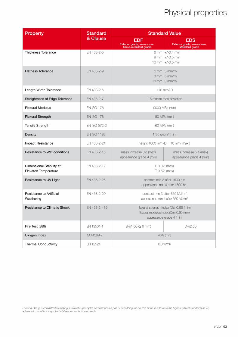
63
Formica Group is committed to making sustainable principles and practices a part of everything we do. We strive to adhere to the highest ethical standards as we advance in our efforts to protect vital resources for future needs.
Physical properties
Property Standard Standard Value & Clause EDF EDS
Thickness Tolerance EN 438-2-5 6 mm +/-0.4 mm
8 mm +/-0.5 mm
10 mm +/-0.5 mm
Flatness Tolerance EN 438-2-9 6 mm 5 mm/m
8 mm 5 mm/m
10 mm 3 mm/m
Length Width Tolerance EN 438-2-6 +10 mm/-0
Straightness of Edge Tolerance EN 438-2-7 1.5 mm/m max deviation
Flexural Modulus EN ISO 178 9000 MPa (min)
Flexural Strength EN ISO 178 80 MPa (min)
Tensile Strength EN ISO 572-2 60 MPa (min)
Density EN ISO 1183 1.35 g/cm3 (min)
Impact Resistance EN 438-2-21 height 1800 mm (D = 10 mm. max.)
Resistance to Wet conditions EN 438-2-15 mass increase 8% (max) mass increase 5% (max)
appearance grade 4 (min) appearance grade 4 (min)
Dimensional Stability at EN 438-2-17 L 0.3% (max)
Elevated Temperature T 0.6% (max)
Resistance to UV Light EN 438-2-28 contrast min 3 after 1500 hrs
appearance min 4 after 1500 hrs
Resistance to Artificial EN 438-2-29 contrast min 3 after 650 MJ/m2
Weathering appearance min 4 after 650 MJ/m2
Resistance to Climatic Shock EN 438-2 - 19 flexural strength index (Ds) 0.95 (min)
flexural modulus index (Dm) 0.95 (min)
appearance grade 4 (min)
Fire Test (SBI) EN 13501-1 B-s1,d0 (> 6 mm) D-s2,d0
Oxygen Index ISO 4589-2 45% (min)
Thermal Conductivity EN 12524 0.3 w/mk
Exterior grade, severe use, flame-retardant grade
Exterior grade, severe use, standard grade
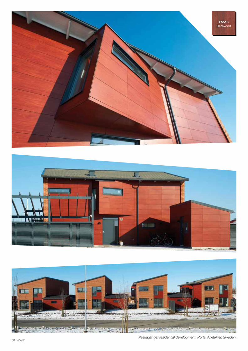
64
F5513Redwood
Påskagänget residential development. Portal Arkitekter. Sweden.

AustriaTel: +49 (0) 180 367 64 [email protected]: +32 2 705 18 [email protected]: +45 43 58 82 [email protected]: +358 3 5800 [email protected]: +33 (0) 3 87 29 10 13 [email protected]: +49 (0) 180 367 64 [email protected]: +31 (0) 70 413 48 [email protected]: +353 1 872 [email protected]: +39 011 [email protected] EastTel: +971 4 3298280 [email protected]: +212 (0) [email protected]: +47 800 13 016 [email protected]: +48 22 516 20 84/[email protected] Tel: +7 495 646 07 25Samples tel: +8 800 333 11 63 [email protected]: +34 902 11 47 [email protected]: +46 42 38 48 [email protected]: +41 44 818 88 [email protected] KingdomTel: +44 191 259 3100Samples tel: +44 191 259 [email protected]
MA
S/E
NG
- 2
/201
4Fo
rmic
a, th
e Fo
rmic
a A
nvil
Dev
ice,
You
niqu
e an
d V
IVIX
are
regi
ster
ed tr
adem
arks
of T
he D
iller
Cor
pora
tion.
©
201
4 Th
e D
iller
Cor
pora
tion.

F0163 Fantasía Marrón Patterns Matte 58
F0905 Mahogany Woods Matte 58
F0949 White Colors S 0502-R50B Matte 58
K1040 Alpino Colors S 0502-G50Y 9010 Matte 58
F1155 Marrón Patterns Matte 58
K1181 Irish Cream Colors S 1005-Y50R Matte 58
K1192 Porcelana Colors S 0505-Y20R 1013 Matte 58
K1238 Carnaval Colors S 1580-Y90R 3001 Matte 58
K1301 Gobi Colors S 1010-Y30R Matte 58
F1614 Punga Punga Wood Woods Matte 58
K1834 Kashmir Colors S 5010-Y30R Matte 58
K1902 Eldorado Colors S 1020-Y20R 1014 Matte 58
K1903 Café Colors S 3020-Y20R Matte 58
K1998 Oslo Colors S 3020-B Matte 58
K2001 Baikal Colors S 1502-Y 9002 Matte 58
K2005 Paprika Colors S 4050-Y80R Matte 58
K2010 Malibu Colors S 1000-N Matte 58
K2020 Tornado Colors S 4500-N 7036 Matte 58
F2200 Dark Chocolate Colors S 8005-Y80R 8017 Matte 58
F2253 Diamond Black Colors S 9000-N 9011 Matte 58
F2288 Peach Colors S 1515-Y40R Matte 58
F2297 Terril Colors S 7502-B 7016 Matte 58
F2302 Doeskin Colors S 2010-Y Matte 58
F2510 Golden Morning Oak Woods Matte 58
F2833 Sandstone Colors S 2010-Y30R Matte 58
F2966 Opal Colors S 1010-G10Y Matte 58
F3007 Pale Olive Colors S 3020-G60Y Matte 58
K3734 Radon Patterns Matte 58
K3735 Krypton Patterns Matte 58
F3855 Clear Maple Woods Matte 58
F4161 Terracotta Colors S 3040-Y60R Matte 58
F4168 Campanula Colors S 1550-R80B Matte 58
F5347 Maui Colors S 2030-B30G Matte 58
F5488 Smoky Brown Pear Woods Matte 58
F5493 Arctic Blue Colors S 0510-R90B Matte 58
F5494 Aquamarine Colors S 0510-B90G Matte 58
F5511 Vosges Pear Woods Matte 58
F5513 Redwood Woods Matte 58
F5530 Savoy Beech Woods Matte 58
F5532 Erable Whisky Woods Matte 58
F6050 Barn Oak Woods Matte 58
F6051 Mission Oak Woods Matte 58
F6052 Cottage Oak Woods Matte 58
F6053 Chalet Oak Woods Matte 58
F6057 Ash Microplank Woods Matte 58
F6058 Bark Microplank Woods Matte 58
F6059 Sienna Cumaru Woods Matte 58
F6060 Marron Cumaru Woods Matte 58
F6063 Rust Materia Patterns Matte 58
F6064 Oxide Materia Patterns Matte 58
F6065 Bronze Materia Patterns Matte 58
F6067 Steel Materia Patterns Matte 58
F6068 Shadow Strié Patterns Matte 58
F6069 Delta Strié Patterns Matte 58
F6071 Millsawn Stone Patterns Matte 58
F6074 Millsawn Slate Patterns Matte 58
F6901 Vibrant Green Colors S 2060-G30Y 6018 Matte 58
F7846 Grotto Colors S 5030-B10G Matte 58
F7851 Spectrum Blue Colors S 3060-R80B Matte 58
F7853 Ocean Grey Colors S 3010-G20Y Matte 58
F7858 Pumice Colors S 2005-Y20R Matte 58
F7884 China Blue Colors S 3020-R90B Matte 58
F7912 Storm Colors S 6502-B 7015 Matte 58
F7927 Folkestone Colors S 2500-N Matte 58
F7940 Spectrum Yellow Colors S 1070-Y10R 1023 Matte 58
F7967 Hunter Green Colors S 7020-G 6005 Matte 58
F7969 Navy Blue Colors S 7020-R80B 5013 Matte 58
F8751 Mojave Colors S 3010-Y30R Matte 58
Engineered Assemblies Head Office 75-6535 Millcreek Drive Mississauga, ON L5N 2M2 . Canada Tel: 1-866-591-7021 [email protected] EngineeredAssemblies.com
Thicknesses(mm)
6.0 8.010.0
Panel Sizes(mm)
3050 x 1300
3660 x 1525
Grades(EN 438-6)
EDS
EDFExterior grade, severe use, standard grade.
Exterior grade, severe use, flame-retardant grade B-s1,d0.
Code Name Range NCS® RAL® Finish
VIVIX® solid phenolic, engineered exterior façade panels have a decorative surface on both sides. Robust and resilient, these rigid homogeneous panels are manufactured by Formica Group, using tough thermosetting resins reinforced with cellulose fibre for added strength and durability.
An acrylic overlay provides enhanced UV protection and VIVIX panels have been rigorously tested for severe use in accordance with EN 438-6, making them ideal for applications in ventilated rainscreen façades and other external building elements.
RAINSCREEN SYSTEM
With visible attachments
With concealed attachments
With visible attachments on wooden substructure
Designs given in this publication have been matched as closely as printing conditions allow. We do recommend, however, that you order samples before final specification, fabrication or installation, as the colour samples in the brochure may differ in shade, hue, tone or brightness to the products purchased.
Please note, not all sizes of panel are available with all certifications.
Code Name Range NCS® RAL® Finish
Numerical listing
Form
ica,
the
Form
ica
Anv
il D
evic
e, Y
ouni
que
and
VIV
IX a
re re
gist
ered
trad
emar
ks o
f The
Dille
r C
orpo
ratio
n.
© 2
014
The
Dille
r C
orpo
ratio
n.
10/2
014Formica Group are FSC® certified and comply with the requirements of FSC. Network of participating European Formica Group sites is shown on certificate number
TT-COC-003588.

F2253Diamond Black
F0949 White
K1192 Porcelana
F8751Mojave
F2297 Terril
K2001Baikal
K1040 Alpino
Matte 58 K1181 Irish Cream
Matte 58
K1301 Gobi
Matte 58 K1902Eldorado
Matte 58
F2302Doeskin
Matte 58F7858Pumice
Matte 58
F7927Folkestone
Matte 58K2010 Malibu
Matte 58
K1834Kashmir
Matte 58
K2020Tornado
Matte 58
F2833 Sandstone
Matte 58
K1903Café
Matte 58
F2200Dark Chocolate
Matte 58
Matte 58F7912Storm
Matte 58
F7851Spectrum Blue
F7969Navy Blue
F5494Aquamarine
F5347Maui
F7846Grotto
F4168Campanula
F2966Opal
Matte 58 F7853Ocean Grey
Matte 58
F2288Peach
Matte 58
F5493Arctic Blue
Matte 58
K1998Oslo
Matte 58 Matte 58
F3007Pale Olive
Matte 58
F6901Vibrant Green
Matte 58 F7967 Hunter Green
Matte 58
F7884China Blue
Matte 58 Matte 58
F7940Spectrum Yellow
Matte 58
F4161Terracotta
Matte 58 K1238Carnaval
Matte 58 K2005Paprika
Matte 58
ColorsColors
Matte 58
F3855Clear Maple
Matte 58 F5532 Erable Whisky
Matte 58Matte 58F5530Savoy Beech
F5511Vosges Pear
Matte 58
F1614Punga Punga Wood
Woods
F2510Golden Morning Oak
Matte 58 F0905Mahogany
Matte 58F5513Redwood
Matte 58F6059Sienna Cumaru
TRUE SCALE
F6060Marron Cumaru
TRUE SCALE
F6053Chalet Oak
F6058Bark Microplank
F6052 Cottage Oak
TRUE SCALE TRUE SCALE TRUE SCALE
Matte 58F5488Smoky Brown Pear
F6050Barn Oak
F6057Ash Microplank
F6051Mission Oak
TRUE SCALE TRUE SCALE TRUE SCALE
Patterns
F1155 Marrón
Matte 58F6074 Millsawn Slate
F6071Millsawn Stone
Matte 58K3735 Krypton
F0163Fantasía Marrón
Matte 58F6069Delta Strié
F6068Shadow Strié
Matte 58K3734Radon
F6064Oxide Materia
F6065Bronze Materia
F6063Rust Materia
F6067Steel Materia
TRUE SCALE
TRUE SCALE
TRUE SCALE TRUE SCALE TRUE SCALE TRUE SCALE
TRUE SCALE
TRUE SCALE
Woods printed samples are shown at approximately 1:2 scale.
VIVIX® by Formica Group offers you TRUE SCALE, the next generation of decorative surfacing represented in the real scale of natural timber and other materials, depicting the patterns, striking veining and rich colour variations of each material across the width of the VIVIX panel.
In exterior, large-scale applications, TRUE SCALE gives you the effect of endless wood grain or the visual richness of aged metals, avoiding the repetition of smaller patterns in more conventional decorative surfaces. With TRUE SCALE enjoy all the practical advantages of robust architectural panels with the exclusive look and scale of real materials, without the associated expense and maintenance issues.
Patterns printed samples are shown at approximately 1:2 scale.
Matte 58NEW
Matte 58NEW
Matte 58NEW
Matte 58NEW
Matte 58NEW
Matte 58NEW
Matte 58NEW
Matte 58NEW
Matte 58NEW
Matte 58NEW
Matte 58NEW
Matte 58NEW
Matte 58NEW
Matte 58NEW
Matte 58NEW
Matte 58NEW
Matte 58NEW
Matte 58NEW
Matte 58NEW
Matte 58NEW
Matte 58NEW
Matte 58NEW
Matte 58NEW
Matte 58NEW
Matte 58NEW
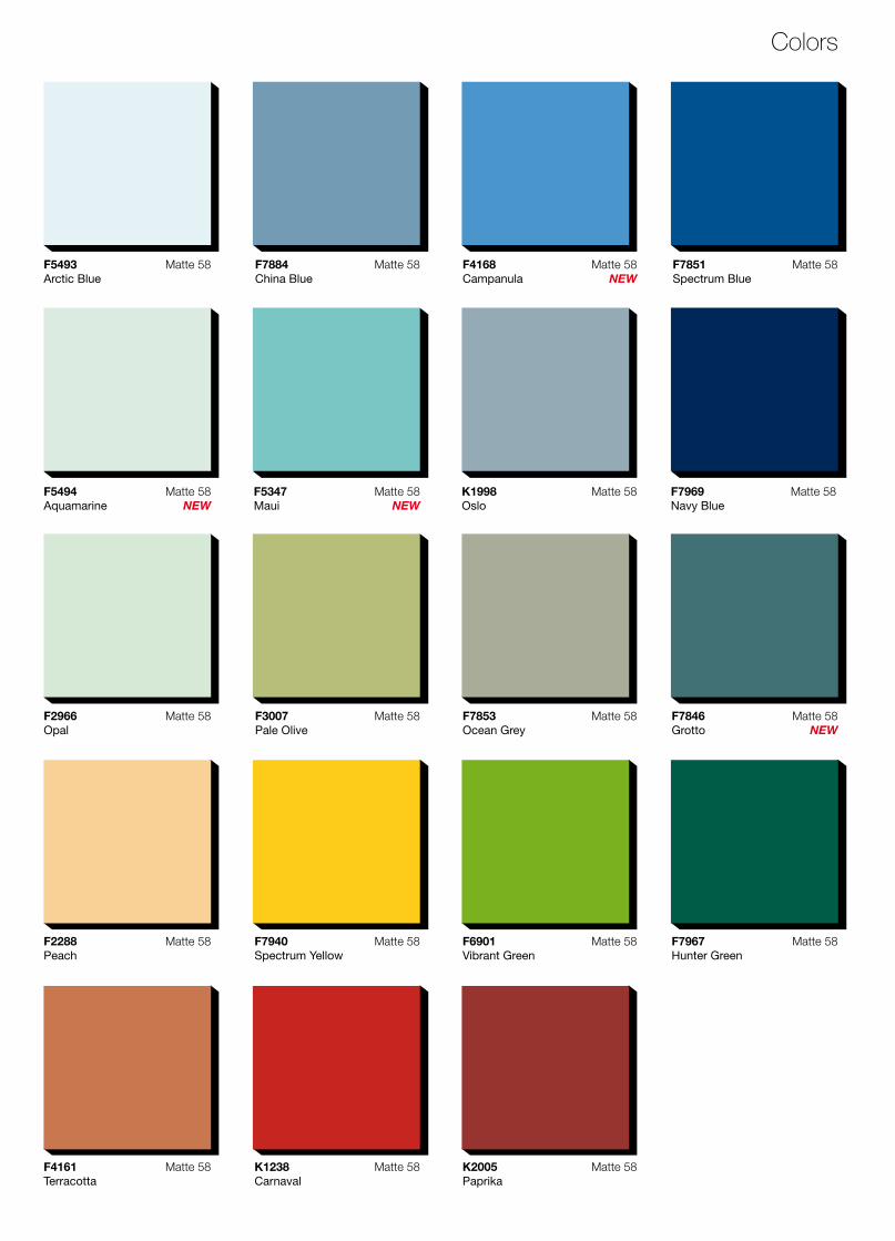
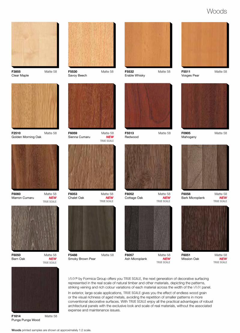
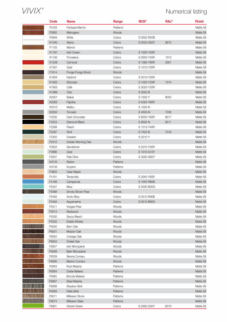
F0163 Fantasía Marrón Patterns Matte 58
F0905 Mahogany Woods Matte 58
F0949 White Colors S 0502-R50B Matte 58
K1040 Alpino Colors S 0502-G50Y 9010 Matte 58
F1155 Marrón Patterns Matte 58
K1181 Irish Cream Colors S 1005-Y50R Matte 58
K1192 Porcelana Colors S 0505-Y20R 1013 Matte 58
K1238 Carnaval Colors S 1580-Y90R 3001 Matte 58
K1301 Gobi Colors S 1010-Y30R Matte 58
F1614 Punga Punga Wood Woods Matte 58
K1834 Kashmir Colors S 5010-Y30R Matte 58
K1902 Eldorado Colors S 1020-Y20R 1014 Matte 58
K1903 Café Colors S 3020-Y20R Matte 58
K1998 Oslo Colors S 3020-B Matte 58
K2001 Baikal Colors S 1502-Y 9002 Matte 58
K2005 Paprika Colors S 4050-Y80R Matte 58
K2010 Malibu Colors S 1000-N Matte 58
K2020 Tornado Colors S 4500-N 7036 Matte 58
F2200 Dark Chocolate Colors S 8005-Y80R 8017 Matte 58
F2253 Diamond Black Colors S 9000-N 9011 Matte 58
F2288 Peach Colors S 1515-Y40R Matte 58
F2297 Terril Colors S 7502-B 7016 Matte 58
F2302 Doeskin Colors S 2010-Y Matte 58
F2510 Golden Morning Oak Woods Matte 58
F2833 Sandstone Colors S 2010-Y30R Matte 58
F2966 Opal Colors S 1010-G10Y Matte 58
F3007 Pale Olive Colors S 3020-G60Y Matte 58
K3734 Radon Patterns Matte 58
K3735 Krypton Patterns Matte 58
F3855 Clear Maple Woods Matte 58
F4161 Terracotta Colors S 3040-Y60R Matte 58
F4168 Campanula Colors S 1550-R80B Matte 58
F5347 Maui Colors S 2030-B30G Matte 58
F5488 Smoky Brown Pear Woods Matte 58
F5493 Arctic Blue Colors S 0510-R90B Matte 58
F5494 Aquamarine Colors S 0510-B90G Matte 58
F5511 Vosges Pear Woods Matte 58
F5513 Redwood Woods Matte 58
F5530 Savoy Beech Woods Matte 58
F5532 Erable Whisky Woods Matte 58
F6050 Barn Oak Woods Matte 58
F6051 Mission Oak Woods Matte 58
F6052 Cottage Oak Woods Matte 58
F6053 Chalet Oak Woods Matte 58
F6057 Ash Microplank Woods Matte 58
F6058 Bark Microplank Woods Matte 58
F6059 Sienna Cumaru Woods Matte 58
F6060 Marron Cumaru Woods Matte 58
F6063 Rust Materia Patterns Matte 58
F6064 Oxide Materia Patterns Matte 58
F6065 Bronze Materia Patterns Matte 58
F6067 Steel Materia Patterns Matte 58
F6068 Shadow Strié Patterns Matte 58
F6069 Delta Strié Patterns Matte 58
F6071 Millsawn Stone Patterns Matte 58
F6074 Millsawn Slate Patterns Matte 58
F6901 Vibrant Green Colors S 2060-G30Y 6018 Matte 58
F7846 Grotto Colors S 5030-B10G Matte 58
F7851 Spectrum Blue Colors S 3060-R80B Matte 58
F7853 Ocean Grey Colors S 3010-G20Y Matte 58
F7858 Pumice Colors S 2005-Y20R Matte 58
F7884 China Blue Colors S 3020-R90B Matte 58
F7912 Storm Colors S 6502-B 7015 Matte 58
F7927 Folkestone Colors S 2500-N Matte 58
F7940 Spectrum Yellow Colors S 1070-Y10R 1023 Matte 58
F7967 Hunter Green Colors S 7020-G 6005 Matte 58
F7969 Navy Blue Colors S 7020-R80B 5013 Matte 58
F8751 Mojave Colors S 3010-Y30R Matte 58
Engineered Assemblies Head Office 75-6535 Millcreek Drive Mississauga, ON L5N 2M2 . Canada Tel: 1-866-591-7021 [email protected] EngineeredAssemblies.com
Thicknesses(mm)
6.0 8.010.0
Panel Sizes(mm)
3050 x 1300
3660 x 1525
Grades(EN 438-6)
EDS
EDFExterior grade, severe use, standard grade.
Exterior grade, severe use, flame-retardant grade B-s1,d0.
Code Name Range NCS® RAL® Finish
VIVIX® solid phenolic, engineered exterior façade panels have a decorative surface on both sides. Robust and resilient, these rigid homogeneous panels are manufactured by Formica Group, using tough thermosetting resins reinforced with cellulose fibre for added strength and durability.
An acrylic overlay provides enhanced UV protection and VIVIX panels have been rigorously tested for severe use in accordance with EN 438-6, making them ideal for applications in ventilated rainscreen façades and other external building elements.
RAINSCREEN SYSTEM
With visible attachments
With concealed attachments
With visible attachments on wooden substructure
Designs given in this publication have been matched as closely as printing conditions allow. We do recommend, however, that you order samples before final specification, fabrication or installation, as the colour samples in the brochure may differ in shade, hue, tone or brightness to the products purchased.
Please note, not all sizes of panel are available with all certifications.
Code Name Range NCS® RAL® Finish
Numerical listing
Form
ica,
the
Form
ica
Anv
il D
evic
e, Y
ouni
que
and
VIV
IX a
re re
gist
ered
trad
emar
ks o
f The
Dille
r C
orpo
ratio
n.
© 2
014
The
Dille
r C
orpo
ratio
n.
10/2
014Formica Group are FSC® certified and comply with the requirements of FSC. Network of participating European Formica Group sites is shown on certificate number
TT-COC-003588.
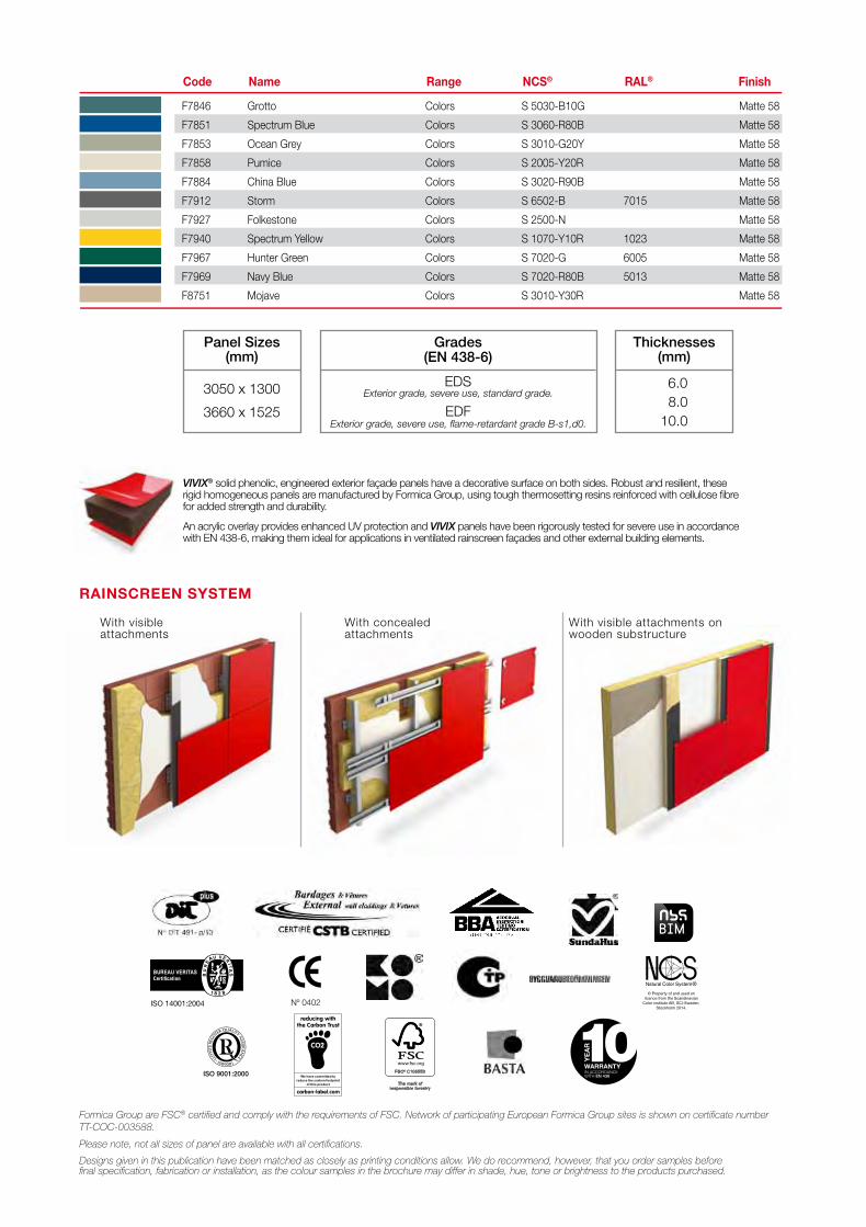
F0163 Fantasía Marrón Patterns Matte 58
F0905 Mahogany Woods Matte 58
F0949 White Colors S 0502-R50B Matte 58
K1040 Alpino Colors S 0502-G50Y 9010 Matte 58
F1155 Marrón Patterns Matte 58
K1181 Irish Cream Colors S 1005-Y50R Matte 58
K1192 Porcelana Colors S 0505-Y20R 1013 Matte 58
K1238 Carnaval Colors S 1580-Y90R 3001 Matte 58
K1301 Gobi Colors S 1010-Y30R Matte 58
F1614 Punga Punga Wood Woods Matte 58
K1834 Kashmir Colors S 5010-Y30R Matte 58
K1902 Eldorado Colors S 1020-Y20R 1014 Matte 58
K1903 Café Colors S 3020-Y20R Matte 58
K1998 Oslo Colors S 3020-B Matte 58
K2001 Baikal Colors S 1502-Y 9002 Matte 58
K2005 Paprika Colors S 4050-Y80R Matte 58
K2010 Malibu Colors S 1000-N Matte 58
K2020 Tornado Colors S 4500-N 7036 Matte 58
F2200 Dark Chocolate Colors S 8005-Y80R 8017 Matte 58
F2253 Diamond Black Colors S 9000-N 9011 Matte 58
F2288 Peach Colors S 1515-Y40R Matte 58
F2297 Terril Colors S 7502-B 7016 Matte 58
F2302 Doeskin Colors S 2010-Y Matte 58
F2510 Golden Morning Oak Woods Matte 58
F2833 Sandstone Colors S 2010-Y30R Matte 58
F2966 Opal Colors S 1010-G10Y Matte 58
F3007 Pale Olive Colors S 3020-G60Y Matte 58
K3734 Radon Patterns Matte 58
K3735 Krypton Patterns Matte 58
F3855 Clear Maple Woods Matte 58
F4161 Terracotta Colors S 3040-Y60R Matte 58
F4168 Campanula Colors S 1550-R80B Matte 58
F5347 Maui Colors S 2030-B30G Matte 58
F5488 Smoky Brown Pear Woods Matte 58
F5493 Arctic Blue Colors S 0510-R90B Matte 58
F5494 Aquamarine Colors S 0510-B90G Matte 58
F5511 Vosges Pear Woods Matte 58
F5513 Redwood Woods Matte 58
F5530 Savoy Beech Woods Matte 58
F5532 Erable Whisky Woods Matte 58
F6050 Barn Oak Woods Matte 58
F6051 Mission Oak Woods Matte 58
F6052 Cottage Oak Woods Matte 58
F6053 Chalet Oak Woods Matte 58
F6057 Ash Microplank Woods Matte 58
F6058 Bark Microplank Woods Matte 58
F6059 Sienna Cumaru Woods Matte 58
F6060 Marron Cumaru Woods Matte 58
F6063 Rust Materia Patterns Matte 58
F6064 Oxide Materia Patterns Matte 58
F6065 Bronze Materia Patterns Matte 58
F6067 Steel Materia Patterns Matte 58
F6068 Shadow Strié Patterns Matte 58
F6069 Delta Strié Patterns Matte 58
F6071 Millsawn Stone Patterns Matte 58
F6074 Millsawn Slate Patterns Matte 58
F6901 Vibrant Green Colors S 2060-G30Y 6018 Matte 58
F7846 Grotto Colors S 5030-B10G Matte 58
F7851 Spectrum Blue Colors S 3060-R80B Matte 58
F7853 Ocean Grey Colors S 3010-G20Y Matte 58
F7858 Pumice Colors S 2005-Y20R Matte 58
F7884 China Blue Colors S 3020-R90B Matte 58
F7912 Storm Colors S 6502-B 7015 Matte 58
F7927 Folkestone Colors S 2500-N Matte 58
F7940 Spectrum Yellow Colors S 1070-Y10R 1023 Matte 58
F7967 Hunter Green Colors S 7020-G 6005 Matte 58
F7969 Navy Blue Colors S 7020-R80B 5013 Matte 58
F8751 Mojave Colors S 3010-Y30R Matte 58
Engineered Assemblies Head Office 75-6535 Millcreek Drive Mississauga, ON L5N 2M2 . Canada Tel: 1-866-591-7021 [email protected] EngineeredAssemblies.com
Thicknesses(mm)
6.0 8.010.0
Panel Sizes(mm)
3050 x 1300
3660 x 1525
Grades(EN 438-6)
EDS
EDFExterior grade, severe use, standard grade.
Exterior grade, severe use, flame-retardant grade B-s1,d0.
Code Name Range NCS® RAL® Finish
VIVIX® solid phenolic, engineered exterior façade panels have a decorative surface on both sides. Robust and resilient, these rigid homogeneous panels are manufactured by Formica Group, using tough thermosetting resins reinforced with cellulose fibre for added strength and durability.
An acrylic overlay provides enhanced UV protection and VIVIX panels have been rigorously tested for severe use in accordance with EN 438-6, making them ideal for applications in ventilated rainscreen façades and other external building elements.
RAINSCREEN SYSTEM
With visible attachments
With concealed attachments
With visible attachments on wooden substructure
Designs given in this publication have been matched as closely as printing conditions allow. We do recommend, however, that you order samples before final specification, fabrication or installation, as the colour samples in the brochure may differ in shade, hue, tone or brightness to the products purchased.
Please note, not all sizes of panel are available with all certifications.
Code Name Range NCS® RAL® Finish
Numerical listingFo
rmic
a, th
e Fo
rmic
a A
nvil
Dev
ice,
You
niqu
e an
d V
IVIX
are
regi
ster
ed tr
adem
arks
of T
he D
iller
Cor
pora
tion.
©
201
4 Th
e D
iller
Cor
pora
tion.
E
.Ass
embl
ies
co-b
rand
/EN
G 1
0/20
14
Formica Group are FSC® certified and comply with the requirements of FSC. Network of participating European Formica Group sites is shown on certificate number TT-COC-003588.
–1–
4648 S. Old Peachtree Rd. | Norcross, GA 30071800.646.3826 (p) | 770.908.2264 (f)
www.imetco.com
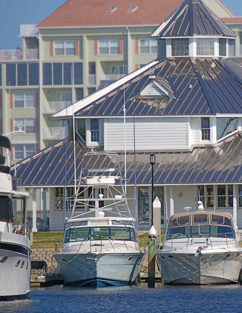
www.imetco.com
R0311
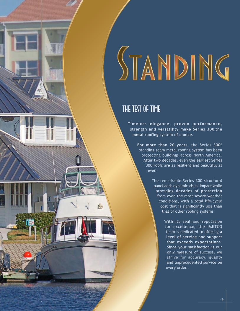
–3–
The Test of Time Timeless elegance, proven performance, strength and versatility make Series 300 the metal roofing system of choice.
For more than 20 years, the Series 300® standing seam metal roofing system has been protecting buildings across North America. After two decades, even the earliest Series 300 roofs are as resilient and beautiful as ever. The remarkable Series 300 structural panel adds dynamic visual impact while providing decades of protection from even the most severe weather conditions, with a total life-cycle cost that is significantly less than that of other roofing systems.
With its zeal and reputation for excellence, the IMETCO team is dedicated to offering a level of service and support that exceeds expectations. Since your satisfaction is our only measure of success, we strive for accuracy, quality and unprecedented service on every order.

R0311
www.imetco.com
TaperingWith Series 300, your tapered metal roof design will achieve the stunning visual impact desired. Our dedicated manufacturing, engineering, and project management teams work closely with designers and contractors
to address installation challenges, reduce waste,
and provide panels that are custom-
tapered for a perfect fit.
IMETCO factory-forms each tapered panel, which may exceed 80-feet in length, from
a single piece of metal, with stiffening
beads adjacent to the vertical legs, to preserve the flat, clean look of the panel’s center.
CurvingWhen it comes to curving, no one does it better than IMETCO. The first to curve a symmetrical seam structural panel, IMETCO can achieve the tightest curves in the industry (having curved to radii as tight as 5’) and minimize oil-canning.
We continue to raise the standards for performance and design flexibility of metal roofing through ongoing product development. Recently, IMETCO celebrated two ground-breaking achievements in Series 300 panel curving: A concave curve; and a continuous, smooth concave-to-convex “S” curve.
These extraordinary S-shaped panels are truly a sight to behold as your eye travels along the reverse-curve radius and continues seamlessly along the
tangent to the standard convex curve.
Whether manufactured in our factory and shipped to you, or field curved on the job site, IMETCO’s curving capabilities are unsurpassed.
Long Panels When your project calls for long panels, rely on the experts. IMETCO’s logistics specialists can coordinate transportation of panels up to 85 feet in length, allowing you the convenience and cost benefits of factory-formed panels for a wider range of projects.
Field Forming and CurvingIMETCO’s field formed panels offer the same warranted, tested, and proven performance as those manufactured in our plant.
Our full-service factory-quality forming equipment features 16 roller stations. It is shipped with a de-coiler to your job site on a 45-foot trailer, and operated on-site by our fabrication experts.
Contact your IMETCO representative for more information.
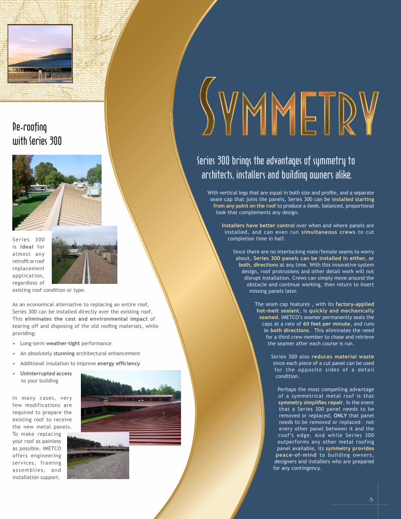
Re-roofing with Series 300
Ser ies 300 is ideal for almost any retrofit or roof replacement application, regardless of existing roof condition or type.
As an economical alternative to replacing an entire roof, Series 300 can be installed directly over the existing roof. This eliminates the cost and environmental impact of tearing off and disposing of the old roofing materials, while providing:
• Long-term weather-tight performance
• An absolutely stunning architectural enhancement
• Additional insulation to improve energy efficiency
• Uninterrupted access to your building
In many cases, very few modifications are required to prepare the existing roof to receive the new metal panels. To make replacing your roof as painless as possible, IMETCO offers engineering services, framing assembl ies, and installation support.
–5–
Series 300 brings the advantages of symmetry to architects, installers and building owners alike.
With vertical legs that are equal in both size and profile, and a separate seam cap that joins the panels, Series 300 can be installed starting
from any point on the roof to produce a sleek, balanced, proportional look that complements any design.
Installers have better control over when and where panels are installed, and can even run simultaneous crews to cut
completion time in half.
Since there are no interlocking male/female seams to worry about, Series 300 panels can be installed in either, or
both, directions at any time. With this innovative system design, roof protrusions and other detail work will not disrupt installation. Crews can simply move around the obstacle and continue working, then return to insert missing panels later.
The seam cap features , with its factory-applied hot-melt sealant, is quickly and mechanically seamed. IMETCO’s seamer permanently seals the caps at a rate of 60 feet per minute, and runs in both directions. This eliminates the need for a third crew member to chase and retrieve the seamer after each course is run.
Series 300 also reduces material waste since each piece of a cut panel can be used for the opposite sides of a detail condition.
Perhaps the most compelling advantage of a symmetrical metal roof is that symmetry simplifies repair. In the event that a Series 300 panel needs to be removed or replaced, ONLY that panel needs to be removed or replaced – not every other panel between it and the roof’s edge. And while Series 300 outperforms any other metal roofing panel available, its symmetry provides peace-of-mind to building owners, designers and installers who are prepared for any contingency.
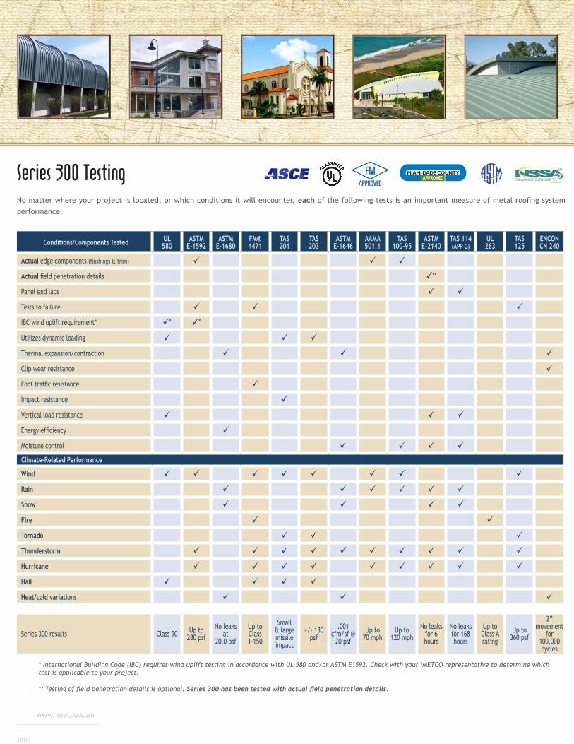
Conditions/Components Tested UL580
ASTM E-1592
ASTM E-1680
FM® 4471
TAS201
TAS203
ASTM E-1646
AAMA501.1
TAS 100-95
ASTM E-2140
TAS 114 (APP G)
UL263
TAS125
ENCONCN 240
Actual edge components (flashings & trim) Actual field penetration details **
Panel end laps Tests to failure IBC wind uplift requirement* * *
Utilizes dynamic loading Thermal expansion/contraction Clip wear resistance Foot traffic resistance Impact resistance Vertical load resistance Energy efficiency Moisture control Climate-Related Performance
Wind Rain Snow Fire Tornado Thunderstorm Hurricane Hail Heat/cold variations
Series 300 results Class 90 Up to 280 psf
No leaks at
20.0 psf
Up to Class 1-150
Small & large missile impact
+/- 130 psf
.001 cfm/sf @
20 psfUp to
70 mphUp to
120 mphNo leaks
for 6 hours
No leaks for 168 hours
Up to Class A rating
Up to 360 psf
2” movement
for 100,000 cycles
* International Building Code (IBC) requires wind uplift testing in accordance with UL 580 and/or ASTM E1592. Check with your IMETCO representative to determine which test is applicable to your project.
** Testing of field penetration details is optional. Series 300 has been tested with actual field penetration details.
Series 300 TestingNo matter where your project is located, or which conditions it will encounter, each of the following tests is an important measure of metal roofing system performance.
R0311
www.imetco.com
MIAMI DADE COUNTYAPPROVED
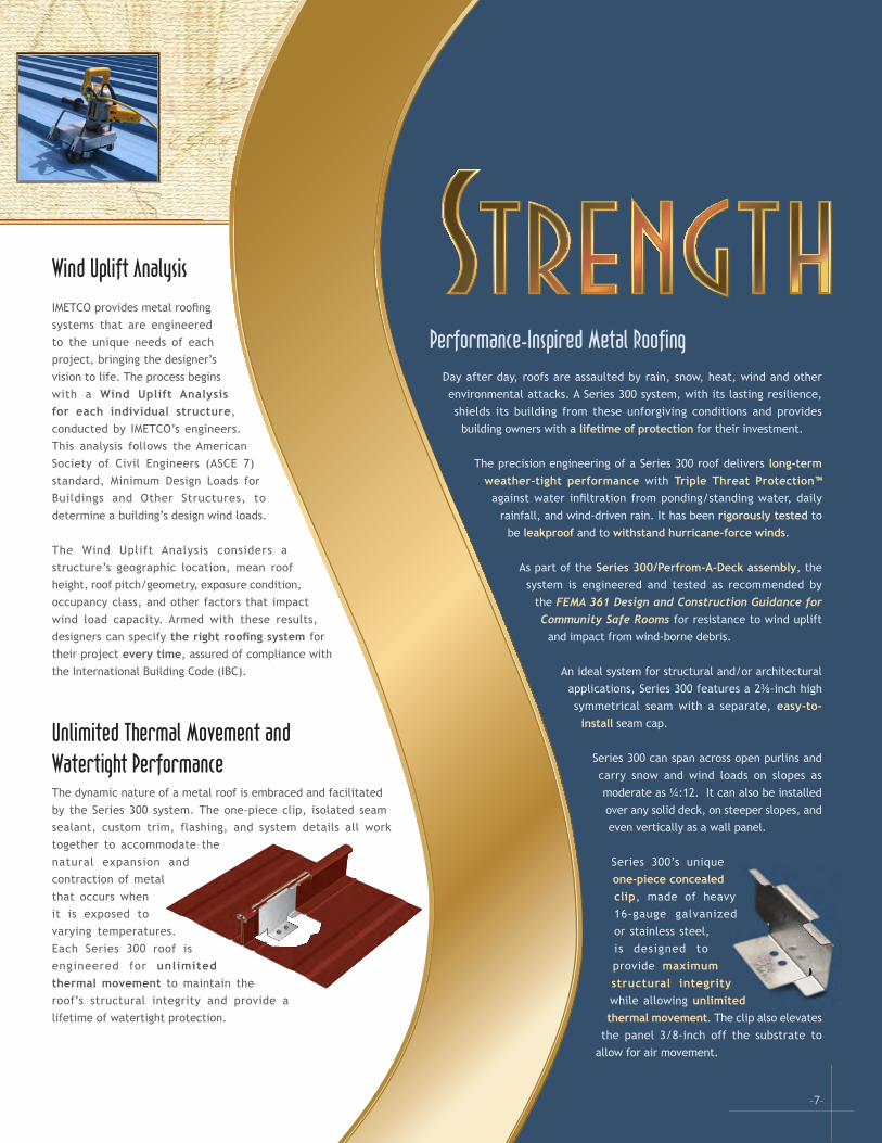
–7–
Performance-Inspired Metal RoofingDay after day, roofs are assaulted by rain, snow, heat, wind and other environmental attacks. A Series 300 system, with its lasting resilience, shields its building from these unforgiving conditions and provides
building owners with a lifetime of protection for their investment.
The precision engineering of a Series 300 roof delivers long-term weather-tight performance with Triple Threat Protection™
against water infiltration from ponding/standing water, daily rainfall, and wind-driven rain. It has been rigorously tested to
be leakproof and to withstand hurricane-force winds.
As part of the Series 300/Perfrom-A-Deck assembly, the system is engineered and tested as recommended by
the FEMA 361 Design and Construction Guidance for Community Safe Rooms for resistance to wind uplift
and impact from wind-borne debris.
An ideal system for structural and/or architectural applications, Series 300 features a 2⅜-inch high symmetrical seam with a separate, easy-to-
install seam cap.
Series 300 can span across open purlins and carry snow and wind loads on slopes as moderate as ¼:12. It can also be installed over any solid deck, on steeper slopes, and even vertically as a wall panel.
Series 300’s unique one-piece concealed clip, made of heavy 16-gauge galvanized or stainless steel, is designed to provide maximum structural integrity while allowing unlimited thermal movement. The clip also elevates
the panel 3/8-inch off the substrate to allow for air movement.
Wind Uplift AnalysisIMETCO provides metal roofing systems that are engineered to the unique needs of each project, bringing the designer’s vision to life. The process begins with a Wind Uplift Analysis for each individual structure, conducted by IMETCO’s engineers. This analysis follows the American Society of Civil Engineers (ASCE 7) standard, Minimum Design Loads for Buildings and Other Structures, to determine a building’s design wind loads.
The Wind Uplift Analysis considers a structure’s geographic location, mean roof height, roof pitch/geometry, exposure condition, occupancy class, and other factors that impact wind load capacity. Armed with these results, designers can specify the right roofing system for their project every time, assured of compliance with the International Building Code (IBC).
Unlimited Thermal Movement and Watertight PerformanceThe dynamic nature of a metal roof is embraced and facilitated by the Series 300 system. The one-piece clip, isolated seam sealant, custom trim, flashing, and system details all work together to accommodate the natural expansion and contraction of metal that occurs when it is exposed to varying temperatures. Each Series 300 roof is engineered for unlimited thermal movement to maintain the roof’s structural integrity and provide a lifetime of watertight protection.
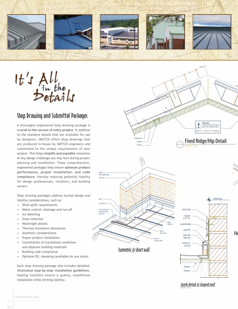
Head assembly detail
Exploded assembly view
Field bend pan using pan-end tool supplied by IMETCO
'Neoprene' head closure factory-formed to �t the panel pro�le
Continuous sealant bead, clear or to match roof panels
Head closure factory-formed to �t panel pro�le and width
Stainless steel fasteners(By erector) typ.
Factory injected hot melt sealant beads
Continuous butyl sealant tape
Ridge/hip trim
O�-set cleat
Sealant bead up vertical legs
1" panel seam cap
Continuous butyl sealant tape
Ridge/hip trim
O�-set cleat
'Neoprene' head closure (factory-formed)
Head closure (factory-formed)
1" panel seam cap
Continuous sealant bead
Valley pan
Corner �ange
And water shieldEdge of ice
Reglet
IMETCO’s PerformaEdge Coping
Turn up valley panel edge inside vertical panel seam.
Valley closureEdge of
Valley panEdge of
Isometric @ short wallArch. Ref.: NoneJamb detail @ sloped roof
Reference pt.
3"
Fasteners
Fastener @ 24" o.c.
Leg cleat x 10'-0" Pop-rivet @ 12" o.c.
Fastener @ each clip w/neoprene washer
Series 300 gable clip
Sealant bed
Jamb trim x 10'-0"
Counter-�ashing
Rod & caulk
Plywood substrate
Underlayment
Fasteners
O�-set Cleat
Seam Cap
Panel Clip
Panel
Ridge/hip Trim
Butyl Sealant Tape,Install Continuously
Substrate
2"
1"
2"
1 3/4"
Specify
Arch. Ref.: None
Fixed Ridge/Hip Detail
Refer to sht #? In the 11" x 17" shop dwgs.
Erector note: Fix panel to clip at this location. Refer to the installation detail.
Fastener AtEach Clip
Series 300Gable Clip
Jamb Trim
Counter�ashing
Fastener@ 12" O.C.
Rod & Caulk
Substrate
Fasteners
Reference pt.
Arch. Ref.: NoneJamb detail @ sloped roof
R0311
www.imetco.com
Shop Drawing and Submittal PackagesA thoroughly engineered shop drawing package is crucial to the success of every project. In addition to the standard details that are available for use by designers, IMETCO offers shop drawings that are produced in-house by IMETCO engineers and customized to the unique requirements of your project. This helps simplify and expedite resolution of any design challenge you may face during project planning and installation. These comprehensive, engineered packages help ensure optimum product performance, proper installation, and code compliance, thereby reducing potential liability for design professionals, installers, and building owners.
Shop drawing packages address myriad design and liability considerations, such as:• Wind uplift requirements• Water control, drainage and run-off• Ice damming• Snow retention• Watertight details• Thermal movement allowances• Aesthetic considerations• Proper product installation• Coordination of transitional conditions and adjacent building materials• Building code compliance• Optional P.E. stamping (available for any state)
Each shop drawing package also includes detailed, illustrated step-by-step installation guidelines, helping installers ensure a quality, expeditious installation while limiting liability.
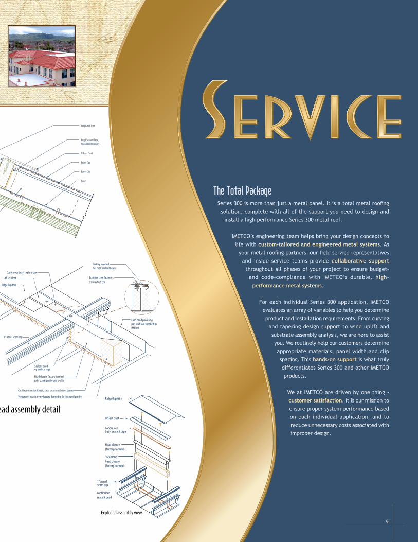
Head assembly detail
Exploded assembly view
Field bend pan using pan-end tool supplied by IMETCO
'Neoprene' head closure factory-formed to �t the panel pro�le
Continuous sealant bead, clear or to match roof panels
Head closure factory-formed to �t panel pro�le and width
Stainless steel fasteners(By erector) typ.
Factory injected hot melt sealant beads
Continuous butyl sealant tape
Ridge/hip trim
O�-set cleat
Sealant bead up vertical legs
1" panel seam cap
Continuous butyl sealant tape
Ridge/hip trim
O�-set cleat
'Neoprene' head closure (factory-formed)
Head closure (factory-formed)
1" panel seam cap
Continuous sealant bead
Underlayment
Fasteners
O�-set Cleat
Seam Cap
Panel Clip
Panel
Ridge/hip Trim
Butyl Sealant Tape,Install Continuously
Substrate
2"
1"
2"
1 3/4"
Specify
Arch. Ref.: None
Fixed Ridge/Hip Detail
Refer to sht #? In the 11" x 17" shop dwgs.
Erector note: Fix panel to clip at this location. Refer to the installation detail.
–9–
The Total PackageSeries 300 is more than just a metal panel. It is a total metal roofing
solution, complete with all of the support you need to design and install a high-performance Series 300 metal roof.
IMETCO’s engineering team helps bring your design concepts to life with custom-tailored and engineered metal systems. As
your metal roofing partners, our field service representatives and inside service teams provide collaborative support
throughout all phases of your project to ensure budget- and code-compliance with IMETCO’s durable, high-
performance metal systems.
For each individual Series 300 application, IMETCO evaluates an array of variables to help you determine product and installation requirements. From curving
and tapering design support to wind uplift and substrate assembly analysis, we are here to assist you. We routinely help our customers determine appropriate materials, panel width and clip spacing. This hands-on support is what truly differentiates Series 300 and other IMETCO products.
We at IMETCO are driven by one thing - customer satisfaction. It is our mission to ensure proper system performance based on each individual application, and to reduce unnecessary costs associated with improper design.
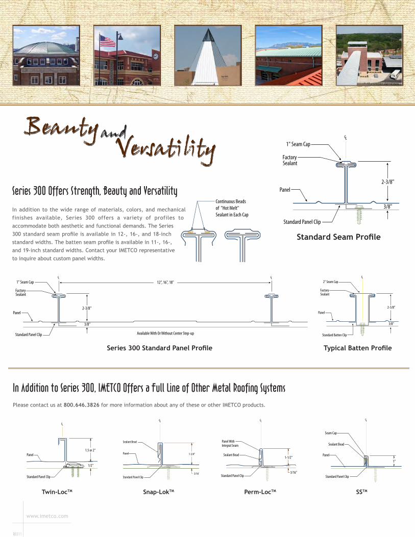
R0311
www.imetco.com
FactorySealant
CL LC
12", 16", 18"
2-3/8"
3/8"
Standard Panel Clip
Panel
1" Seam Cap
Available With Or Without Center Step-up
Series 300 Offers Strength, Beauty and Versatility In addition to the wide range of materials, colors, and mechanical finishes available, Series 300 offers a variety of profiles to accommodate both aesthetic and functional demands. The Series 300 standard seam profile is available in 12-, 16-, and 18-inch standard widths. The batten seam profile is available in 11-, 16-, and 19-inch standard widths. Contact your IMETCO representative to inquire about custom panel widths.
Continuous Beads of "Hot Melt" Sealant in Each Cap
In Addition to Series 300, IMETCO Offers a Full Line of Other Metal Roofing SystemsPlease contact us at 800.646.3826 for more information about any of these or other IMETCO products.
Series 300 Standard Panel Profile
CL2" Seam Cap
Panel
Standard Batten Clip
2-3/8"
3/8"
FactorySealant
Typical Batten Profile
FactorySealant
LC
2-3/8"
Standard Panel Clip
1" Seam Cap
Panel
3/8"
Standard Seam Profile
Snap-LokTM SSTM
LC
1"
Standard Panel Clip
Panel
Sealant Bead
Seam Cap
Perm-LocTM
LC
3/16"
1-1/2"Sealant Bead
Panel With
Standard Panel Clip
Integral Seam
Twin-LocTM
CL
1/2"
Standard Panel Clip
Panel
2-piece Panel Clip24 Ga. Galvanized Steel
Twin-Loc Seaming Operation
STEP #3STEP #2STEP #1
1/2"
1"
2 7/8"
1 5/16"
1 3/4"
Gable Clip
18 Ga. Stainless Steel18 Ga. Galv. Steel
1.5 or 2"
CL
1-3/4"
Standard Panel Clip
Panel
Sealant Bead
3/16"
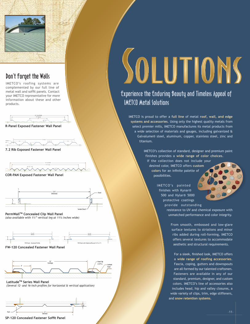
Don’t Forget the WallsIMETCO’s roofing systems are complemented by our full line of metal wall and soffit panels. Contact your IMETCO representative for more information about these and other products.
–11–
Experience the Enduring Beauty and Timeless Appeal of IMETCO Metal Solutions
IMETCO is proud to offer a full line of metal roof, wall, and edge systems and accessories. Using only the highest quality metals from select premier mills, IMETCO manufactures its metal products from
a wide selection of materials and gauges, including galvanized & Galvalume® steel, aluminum, copper, stainless steel, zinc and
titanium.
IMETCO’s collection of standard, designer and premium paint finishes provides a wide range of color choices. If the collection does not include your
desired color, IMETCO offers custom colors for an infinite palette of
possibilities.
IMETCO’s pa inted finishes with Kynar®
500 and Hylar® 5000 protective coatings provide outstanding
resistance to UV and chemical exposure with unmatched performance and color integrity.
From smooth, embossed and low-glare surface textures to striations and minor ribs added during roll-forming, IMETCO offers several textures to accommodate aesthetic and structural requirements.
For a sleek, finished look, IMETCO offers a wide range of roofing accessories. Fascia, coping, gutters and downspouts are all formed by our talented craftsmen. Fasteners are available in any of our standard, premium, designer, and custom colors. IMETCO’s line of accessories also includes head, hip and valley closures, a
wide variety of clips, trim, edge stiffeners, and snow retention systems.
36" Coverage39¼" Overall Width
12"
1¼"
R-Panel Exposed Fastener Wall Panel
7.2 Rib Exposed Fastener Wall Panel
34 2∕3" Coverage
39 3∕8" Overall Width
2 2∕3"
7/8"
COR-PAN Exposed Fastener Wall Panel
1"
LCCL
12" or 16”(Nominal)
FW Panel - Standard Profile FW Panel with Optional Reveal (1/2” or 1”)
LCCL12" or 16”(Nominal)
1"
FW-120 Concealed Fastener Wall Panel
CLLC
(Nominal)12¾"
1"
Panel
Sealant Bead
PermWall 1.0 Flush Pro�le
CLLC
(Nominal)11¾" Panel
Sealant Bead
1½"
PermWall 1.5 Flush Pro�le
PermWall 1.0 Single Vee Pro�le
CLLC
(Nominal)12¾"
1"
Panel
Sealant Bead
PermWall 1.5 Single Vee Pro�le
CLLC
(Nominal)11¾" Panel
Sealant Bead
1½"
CLLC
(Nominal)12¾"
1"
Panel
Sealant Bead
PermWall 1.0 Double Vee Pro�le
CLLC
(Nominal)11¾" Panel
Sealant Bead
1½"
PermWall 1.5 Double Vee Pro�le
PermWallTM Concealed Clip Wall Panel(also available with 1½” vertical leg at 11¾ inches wide)
CL LC(Nominal)12"Panel
7/16"
SP-120 Concealed Fastener Soffit Panel
16"Coverage
4"
Panel Clip @ 24"o.c. Latitude
Panel
LatitudeTM Series Wall Panel(Several 12- and 16-inch profiles for horizontal & vertical application)
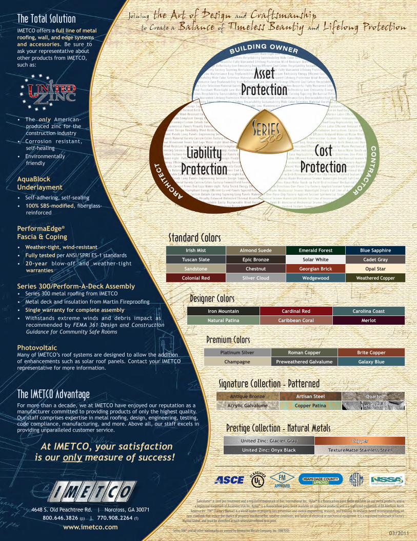
www.imetco.com
R0311
Premium ColorsPlatinum Silver Roman Copper Brite Copper
Champagne Preweathered Galvalume Galaxy Blue
The Total SolutionIMETCO offers a full line of metal roofing, wall, and edge systems and accessories. Be sure to ask your representative about other products from IMETCO, such as:
• The only American- produced zinc for the construction industry
• Corrosion resistant, self-healing
• Environmentally friendly
AquaBlock Underlayment• Self-adhering, self-sealing• 100% SBS-modified, fiberglass-
reinforced
PerformaEdge® Fascia & Coping• Weather-tight, wind-resistant• Fully tested per ANSI/SPRI ES-1 standards• 20-year blow-off and weather-tight
warranties
Series 300/Perform-A-Deck Assembly• Series 300 metal roofing from IMETCO• Metal deck and insulation from Martin Fireproofing• Single warranty for complete assembly• Withstands extreme winds and debris impact as
recommended by FEMA 361 Design and Construction Guidance for Community Safe Rooms
Photovoltaic Many of IMETCO’s roof systems are designed to allow the addition of enhancements such as solar roof panels. Contact your IMETCO representative for more information.
The IMETCO AdvantageFor more than a decade, we at IMETCO have enjoyed our reputation as a manufacturer committed to providing products of only the highest quality. Our staff comprises expertise in metal roofing, design, engineering, testing, code compliance, manufacturing, and more. Above all, our staff excels in providing unparalleled customer service.
At IMETCO, your satisfaction is our only measure of success!
4648 S. Old Peachtree Rd. | Norcross, GA 30071800.646.3826 (p) | 770.908.2264 (f)
www.imetco.com
Standard ColorsIrish Mist Almond Suede Emerald Forest Blue Sapphire
Tuscan Slate Epic Bronze Solar White Cadet Gray
Sandstone Chestnut Georgian Brick Opal Star
Colonial Red Silver Cloud Wedgewood Weathered Copper
Designer ColorsIron Mountain Cardinal Red Carolina Coast
Natural Patina Caribbean Coral Merlot
Asset Protection
Liability Protection
Cost Protection
Galvalume® is steel pre-treatment and a registered trademark of Biec International Inc. Hylar® is a fluorocarbon paint finish available on our metal products, and is a registered trademark of Ausimont USA Inc. Kynar® is a fluorocarbon paint finish available on our metal products, and is a registered trademark of Elf Atochem North
America Inc. FM® (Factory Mutual) is a world leader in property loss prevention and control engineering, research, and training. Its research-based recommendations set new standards that reduce the chance of property loss due to fire, weather conditions, and failure of electrical or mechanical equipment. It is a registered trademark of Factory
Mutual Global, and must be identified as such whenever referred to in print.
Series 300® and all other trademarks are owned by Innovative Metals Company, Inc. (IMETCO). 03/2011
Signature Collection - PatternedAntique Bronze Artisan Steel Quartz
Acrylic Galvalume Copper Patina Field Stone
Prestige Collection - Natural MetalsUnited Zinc: Glacier Gray Copper
United Zinc: Onyx Black TextureMatte Stainless Steel
MIAMI DADE COUNTYAPPROVED
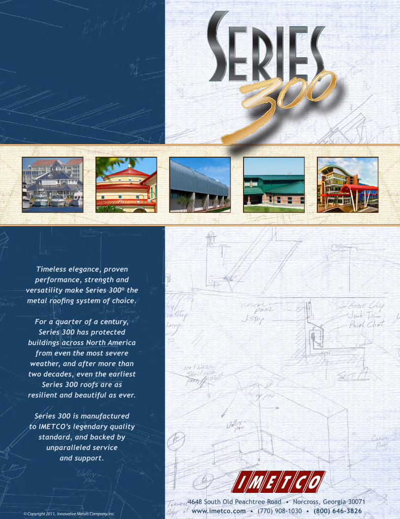
2070SteelDrivesTucker,Georgia30084 800.646.3826(p)s770.908.1030(p)s770.908.2264(f)
www.imetco.comR030911
Testing
Conditions/ComponentsTested UL580
ASTME-1592
ASTME-1680
FM®4471
TAS201
TAS203
ASTME-1646
AAMA501.1
TAS100-95
ASTME-2140
TAS114(APPG)
UL263
TAS125
ENCONCN240
Actual flashings and trim Actual field penetration details **
Panel end laps Tests to failure IBC wind uplift requirement* * *
Utilizes dynamic loading Thermal expansion/contraction Clip wear resistance Foot traffic resistance Impact resistance Vertical load resistance Energy efficiency Moisture control Climate-RelatedPerformance
Wind Rain Snow Fire Tornado Thunderstorm Hurricane Hail Heat/coldvariations
Series300Results Class 90 Up to 280 psf
.001 cfm/sf @ 20
psf
Up to Class 1-150
Small & large missile impact
+/- 130 psf
No leaks at
20.0 psfUp to
70 mphUp to
120 mphNo leaks
for 6 hours
No leaks for 168 hours
Up to Class A rating
Up to 360 psf
2” movement for 100,000
cycles
* International Building Code (IBC) requires wind uplift testing in accordance with UL 580 and/or ASTM E1592. Check with your IMETCO representative to determine which test is applicable to your project.
** Testing of field penetration details is optional. Series 300 has been tested with actual field penetration details.
MIAMI DADE COUNTYAPPROVED
4648 South Old Peachtree Road • Norcross, Georgia 30071www.imetco.com • (770) 908-1030 • (800)646-3826© Copyright 2011, Innovative Metals Company, Inc.
Timeless elegance, proven performance, strength and
versatility make Series 300® the metal roofing system of choice.
For a quarter of a century, Series 300 has protected
buildings across North America from even the most severe
weather, and after more than two decades, even the earliest
Series 300 roofs are as resilient and beautiful as ever.
Series 300 is manufactured to IMETCO’s legendary quality
standard, and backed by unparalleled service
and support.
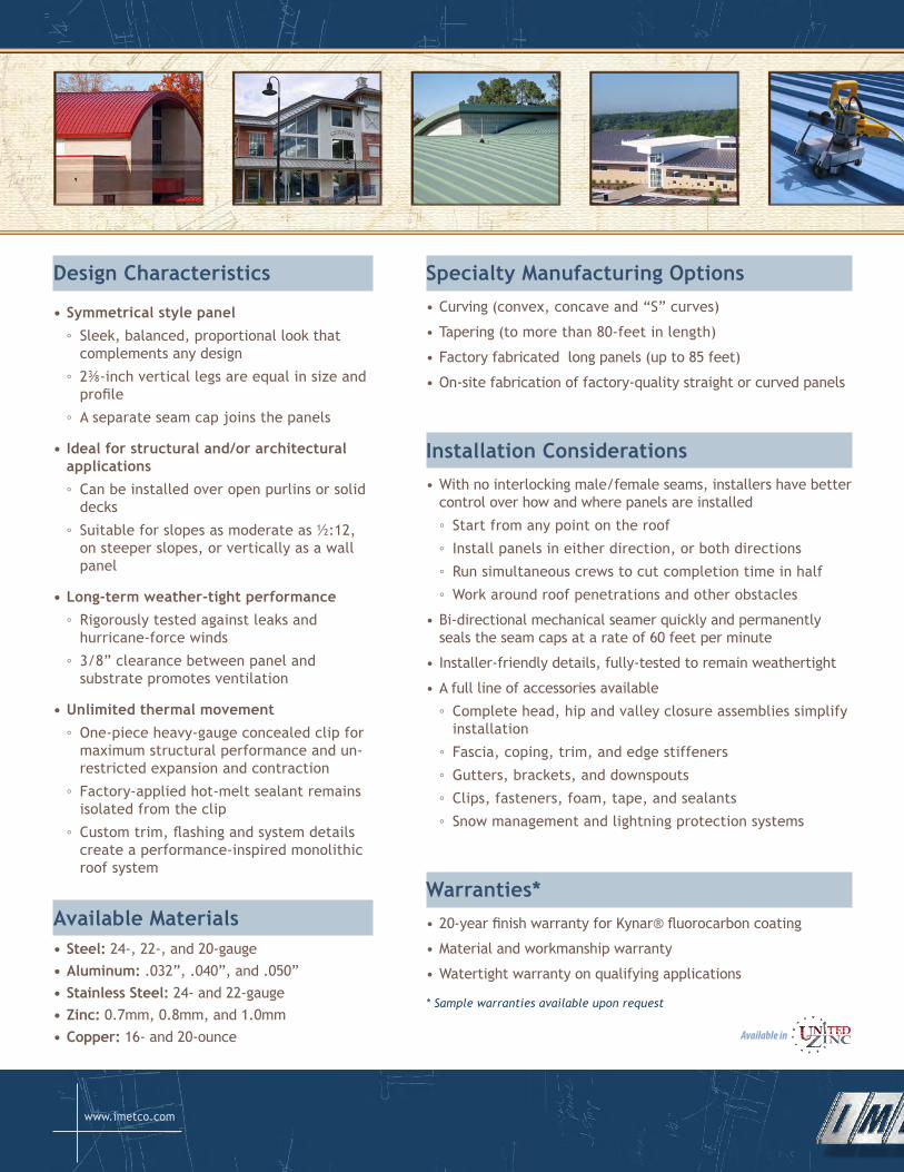
FactorySealant
CL LC
12", 16", 18"
2-3/8"
3/8"
Standard Panel Clip
Panel
1" Seam Cap
Available With Or Without Center Step-up
Series300StandardPanelProfile
CL2" Seam Cap
Panel
Standard Batten Clip
2-3/8"
3/8"
FactorySealant
TypicalBattenProfile
FactorySealant
LC
2-3/8"
Standard Panel Clip
1" Seam Cap
Panel
3/8"
StandardSeamProfileProfiles
•Standardprofile ◦ Features a center stiffening rib between two pencil beads
◦ Available without center stiffening rib
◦ 12-, 16-, and 18-inch panel widths
◦ 1-inch seam cap
•Battenprofile ◦ Features a center stiffening rib between two pencil beads
◦ Available with or without center stiffening rib
◦ 11-, 16-, and 19-inch panel widths
◦ 2-inch batten cap
•Originalprofile ◦ Features four evenly-spaced pencil beads
◦ 12-, 16-, and 18-inch widths with one-inch standard seam
◦ 11-, 16-, and 19-inch widths with two-inch batten seam
•PVFlatprofile ◦ Features a flat pan designed to accept thin-film solar panels
◦ 16- and 18-inch widths with one-inch standard seam
◦ 19-inch width with two-inch batten seam
(800) 646-3826www.imetco.com
DesignCharacteristics
•Symmetricalstylepanel ◦ Sleek, balanced, proportional look that complements any design
◦ 2⅜-inch vertical legs are equal in size and profile
◦ A separate seam cap joins the panels
•Idealforstructuraland/orarchitecturalapplications ◦ Can be installed over open purlins or solid decks
◦ Suitable for slopes as moderate as ½:12, on steeper slopes, or vertically as a wall panel
•Long-termweather-tightperformance ◦ Rigorously tested against leaks and hurricane-force winds
◦ 3/8” clearance between panel and substrate promotes ventilation
•Unlimitedthermalmovement ◦ One-piece heavy-gauge concealed clip for maximum structural performance and un-restricted expansion and contraction
◦ Factory-applied hot-melt sealant remains isolated from the clip
◦ Custom trim, flashing and system details create a performance-inspired monolithic roof system
AvailableMaterials•Steel: 24-, 22-, and 20-gauge•Aluminum: .032”, .040”, and .050”•StainlessSteel: 24- and 22-gauge•Zinc:0.7mm, 0.8mm, and 1.0mm•Copper: 16- and 20-ounce Available in
SpecialtyManufacturingOptions• Curving (convex, concave and “S” curves)
• Tapering (to more than 80-feet in length)
• Factory fabricated long panels (up to 85 feet)
• On-site fabrication of factory-quality straight or curved panels
InstallationConsiderations• With no interlocking male/female seams, installers have better
control over how and where panels are installed
◦ Start from any point on the roof
◦ Install panels in either direction, or both directions
◦ Run simultaneous crews to cut completion time in half
◦ Work around roof penetrations and other obstacles
• Bi-directional mechanical seamer quickly and permanently seals the seam caps at a rate of 60 feet per minute
• Installer-friendly details, fully-tested to remain weathertight
• A full line of accessories available
◦ Complete head, hip and valley closure assemblies simplify installation
◦ Fascia, coping, trim, and edge stiffeners
◦ Gutters, brackets, and downspouts
◦ Clips, fasteners, foam, tape, and sealants
◦ Snow management and lightning protection systems
Warranties*• 20-year finish warranty for Kynar® fluorocarbon coating
• Material and workmanship warranty
• Watertight warranty on qualifying applications
* Sample warranties available upon request

FactorySealant
CL LC
12", 16", 18"
2-3/8"
3/8"
Standard Panel Clip
Panel
1" Seam Cap
Available With Or Without Center Step-up
Series300StandardPanelProfile
CL2" Seam Cap
Panel
Standard Batten Clip
2-3/8"
3/8"
FactorySealant
TypicalBattenProfile
FactorySealant
LC
2-3/8"
Standard Panel Clip
1" Seam Cap
Panel
3/8"
StandardSeamProfileProfiles
•Standardprofile ◦ Features a center stiffening rib between two pencil beads
◦ Available without center stiffening rib
◦ 12-, 16-, and 18-inch panel widths
◦ 1-inch seam cap
•Battenprofile ◦ Features a center stiffening rib between two pencil beads
◦ Available with or without center stiffening rib
◦ 11-, 16-, and 19-inch panel widths
◦ 2-inch batten cap
•Originalprofile ◦ Features four evenly-spaced pencil beads
◦ 12-, 16-, and 18-inch widths with one-inch standard seam
◦ 11-, 16-, and 19-inch widths with two-inch batten seam
•PVFlatprofile ◦ Features a flat pan designed to accept thin-film solar panels
◦ 16- and 18-inch widths with one-inch standard seam
◦ 19-inch width with two-inch batten seam
(800) 646-3826www.imetco.com
DesignCharacteristics
•Symmetricalstylepanel ◦ Sleek, balanced, proportional look that complements any design
◦ 2⅜-inch vertical legs are equal in size and profile
◦ A separate seam cap joins the panels
•Idealforstructuraland/orarchitecturalapplications ◦ Can be installed over open purlins or solid decks
◦ Suitable for slopes as moderate as ½:12, on steeper slopes, or vertically as a wall panel
•Long-termweather-tightperformance ◦ Rigorously tested against leaks and hurricane-force winds
◦ 3/8” clearance between panel and substrate promotes ventilation
•Unlimitedthermalmovement ◦ One-piece heavy-gauge concealed clip for maximum structural performance and un-restricted expansion and contraction
◦ Factory-applied hot-melt sealant remains isolated from the clip
◦ Custom trim, flashing and system details create a performance-inspired monolithic roof system
AvailableMaterials•Steel: 24-, 22-, and 20-gauge•Aluminum: .032”, .040”, and .050”•StainlessSteel: 24- and 22-gauge•Zinc:0.7mm, 0.8mm, and 1.0mm•Copper: 16- and 20-ounce Available in
SpecialtyManufacturingOptions• Curving (convex, concave and “S” curves)
• Tapering (to more than 80-feet in length)
• Factory fabricated long panels (up to 85 feet)
• On-site fabrication of factory-quality straight or curved panels
InstallationConsiderations• With no interlocking male/female seams, installers have better
control over how and where panels are installed
◦ Start from any point on the roof
◦ Install panels in either direction, or both directions
◦ Run simultaneous crews to cut completion time in half
◦ Work around roof penetrations and other obstacles
• Bi-directional mechanical seamer quickly and permanently seals the seam caps at a rate of 60 feet per minute
• Installer-friendly details, fully-tested to remain weathertight
• A full line of accessories available
◦ Complete head, hip and valley closure assemblies simplify installation
◦ Fascia, coping, trim, and edge stiffeners
◦ Gutters, brackets, and downspouts
◦ Clips, fasteners, foam, tape, and sealants
◦ Snow management and lightning protection systems
Warranties*• 20-year finish warranty for Kynar® fluorocarbon coating
• Material and workmanship warranty
• Watertight warranty on qualifying applications
* Sample warranties available upon request
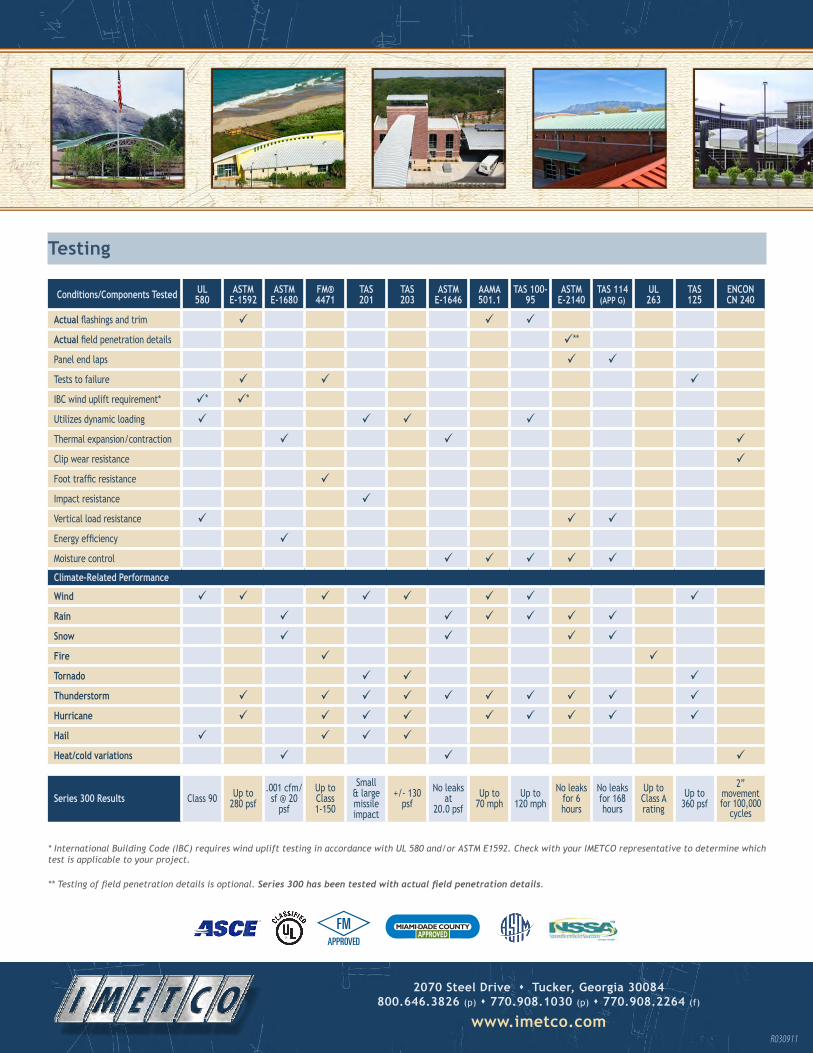
2070SteelDrivesTucker,Georgia30084 800.646.3826(p)s770.908.1030(p)s770.908.2264(f)
www.imetco.comR030911
Testing
Conditions/ComponentsTested UL580
ASTME-1592
ASTME-1680
FM®4471
TAS201
TAS203
ASTME-1646
AAMA501.1
TAS100-95
ASTME-2140
TAS114(APPG)
UL263
TAS125
ENCONCN240
Actual flashings and trim Actual field penetration details **
Panel end laps Tests to failure IBC wind uplift requirement* * *
Utilizes dynamic loading Thermal expansion/contraction Clip wear resistance Foot traffic resistance Impact resistance Vertical load resistance Energy efficiency Moisture control Climate-RelatedPerformance
Wind Rain Snow Fire Tornado Thunderstorm Hurricane Hail Heat/coldvariations
Series300Results Class 90 Up to 280 psf
.001 cfm/sf @ 20
psf
Up to Class 1-150
Small & large missile impact
+/- 130 psf
No leaks at
20.0 psfUp to
70 mphUp to
120 mphNo leaks
for 6 hours
No leaks for 168 hours
Up to Class A rating
Up to 360 psf
2” movement for 100,000
cycles
* International Building Code (IBC) requires wind uplift testing in accordance with UL 580 and/or ASTM E1592. Check with your IMETCO representative to determine which test is applicable to your project.
** Testing of field penetration details is optional. Series 300 has been tested with actual field penetration details.
MIAMI DADE COUNTYAPPROVED
4648 South Old Peachtree Road • Norcross, Georgia 30071www.imetco.com • (770) 908-1030 • (800)646-3826© Copyright 2011, Innovative Metals Company, Inc.
Timeless elegance, proven performance, strength and
versatility make Series 300® the metal roofing system of choice.
For a quarter of a century, Series 300 has protected
buildings across North America from even the most severe
weather, and after more than two decades, even the earliest
Series 300 roofs are as resilient and beautiful as ever.
Series 300 is manufactured to IMETCO’s legendary quality
standard, and backed by unparalleled service
and support.
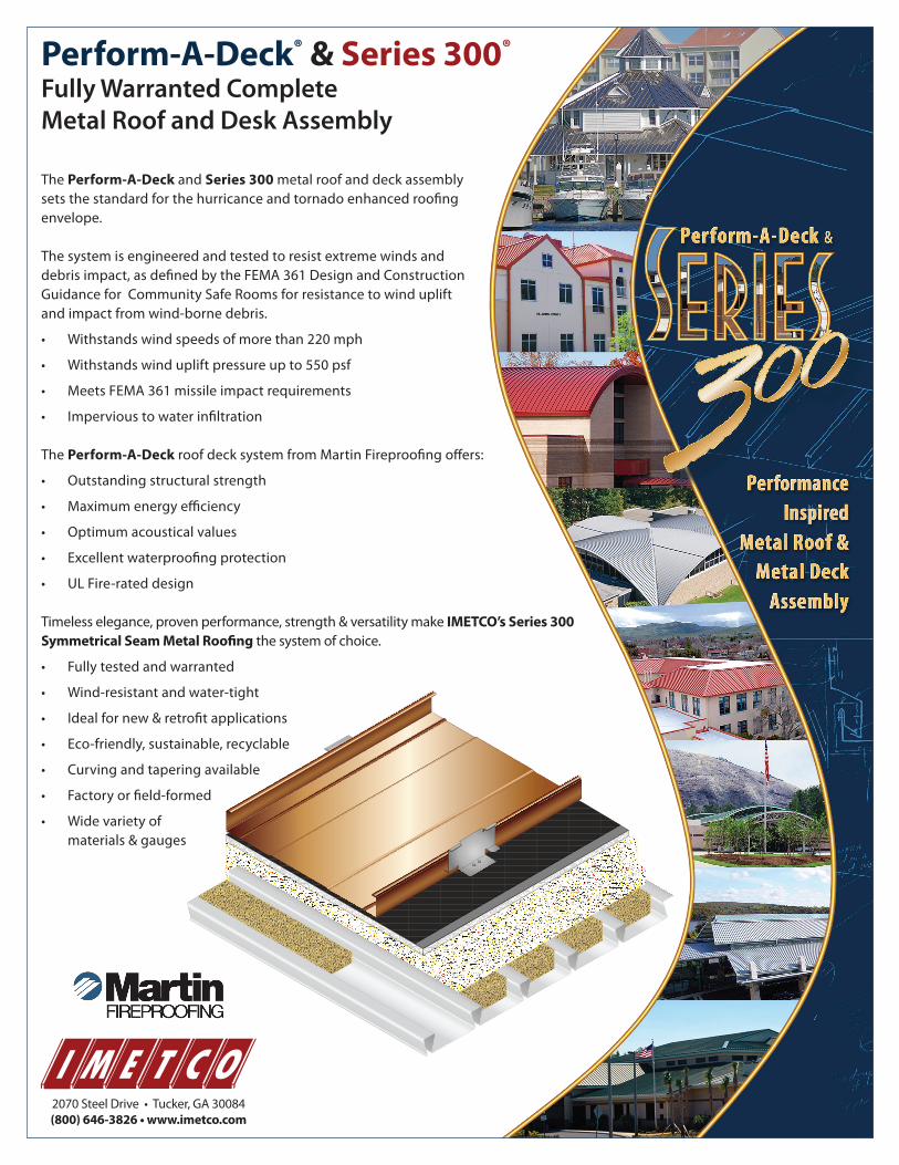
Perform-A-Deck® & Series 300®
Fully Warranted CompleteMetal Roof and Desk Assembly
The Perform-A-Deck and Series 300 metal roof and deck assembly sets the standard for the hurricance and tornado enhanced roofing envelope.
The system is engineered and tested to resist extreme winds and debris impact, as defined by the FEMA 361 Design and Construction Guidance for Community Safe Rooms for resistance to wind uplift and impact from wind-borne debris.
• Withstandswindspeedsofmorethan220mph
• Withstandswindupliftpressureupto550psf
• MeetsFEMA361missileimpactrequirements
• Impervioustowaterinfiltration
The Perform-A-Deck roof deck system from Martin Fireproofing offers:
• Outstandingstructuralstrength
• Maximumenergyefficiency
• Optimumacousticalvalues
• Excellentwaterproofingprotection
• ULFire-rateddesign
Timeless elegance, proven performance, strength & versatility make IMETCO’s Series 300 Symmetrical Seam Metal Roofing the system of choice.
• Fullytestedandwarranted
• Wind-resistantandwater-tight
• Idealfornew&retrofitapplications
• Eco-friendly,sustainable,recyclable
• Curvingandtaperingavailable
• Factoryorfield-formed
• Widevarietyof materials & gauges
2070SteelDrive•Tucker,GA30084(800) 646-3826 • www.imetco.com
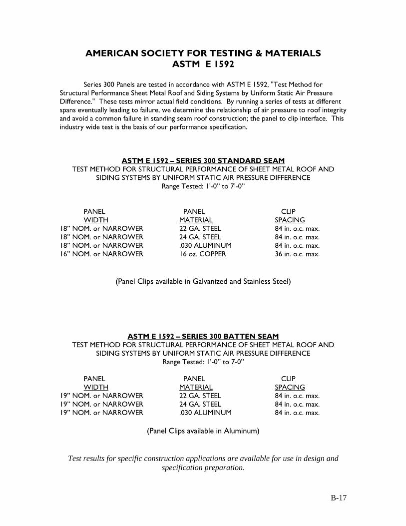
AMERICAN SOCIETY FOR TESTING & MATERIALS ASTM E 1592
Series 300 Panels are tested in accordance with ASTM E 1592, "Test Method for Structural Performance Sheet Metal Roof and Siding Systems by Uniform Static Air Pressure Difference." These tests mirror actual field conditions. By running a series of tests at different spans eventually leading to failure, we determine the relationship of air pressure to roof integrity and avoid a common failure in standing seam roof construction; the panel to clip interface. This industry wide test is the basis of our performance specification.
ASTM E 1592 – SERIES 300 STANDARD SEAM TEST METHOD FOR STRUCTURAL PERFORMANCE OF SHEET METAL ROOF AND
SIDING SYSTEMS BY UNIFORM STATIC AIR PRESSURE DIFFERENCE Range Tested: 1’-0” to 7’-0”
PANEL PANEL CLIP WIDTH MATERIAL SPACING
18” NOM. or NARROWER 22 GA. STEEL 84 in. o.c. max. 18” NOM. or NARROWER 24 GA. STEEL 84 in. o.c. max. 18” NOM. or NARROWER .030 ALUMINUM 84 in. o.c. max. 16” NOM. or NARROWER 16 oz. COPPER 36 in. o.c. max.
(Panel Clips available in Galvanized and Stainless Steel)
ASTM E 1592 – SERIES 300 BATTEN SEAM TEST METHOD FOR STRUCTURAL PERFORMANCE OF SHEET METAL ROOF AND
SIDING SYSTEMS BY UNIFORM STATIC AIR PRESSURE DIFFERENCE Range Tested: 1’-0” to 7-0”
PANEL PANEL CLIP WIDTH MATERIAL SPACING
19” NOM. or NARROWER 22 GA. STEEL 84 in. o.c. max. 19” NOM. or NARROWER 24 GA. STEEL 84 in. o.c. max. 19” NOM. or NARROWER .030 ALUMINUM 84 in. o.c. max.
(Panel Clips available in Aluminum)
Test results for specific construction applications are available for use in design and specification preparation.
B-17

UNDERWRITER LABORATIORIES UL 580 – CLASS 90
Standard for Tests for Uplift Resistance of Roof Assemblies
The following excerpt is taken form the Introduction and Scope of the UL Standard. The method of test specified in this standard is intended to determine the uplift resistance of roof assemblies consisting of the roof deck and roof covering materials. It is applicable to any type of roof assembly which is adaptable to the test equipment. Tests to evaluate other potential hazards of roof assemblies are not within the scope of these requirements. The purpose of this test is to evaluate the comparative resistance of roof assemblies to positive and negative pressures. The test evaluates the roof deck, its attachment to supports, and roof covering materials. It does not evaluate roofs adjacent to chimneys, overhanging eaves, or similar construction, connections of the assembly to main structural supports (girders, columns, or other supports), structural integrity of secondary supports (purlins, joist, bulb tees, or the like), or deterioration of roofing materials.
UL 580 CLASS 90 – SERIES 300 STANDING SEAM
UL CONSTRUCTION NO. 268 – PURLIN (16 GA.) TESTING SUBSTRATE
PANEL PANEL CLIP WIDTH MATERIAL SPACING
18” NOM. or NARROWER 24 GA. STEEL 60 in. o.c. max. 18” NOM. or NARROWER .030 ALUMINUM 48 in. o.c. max.
UL CONSTRUCTION NO. 268A – METAL DECKING (22 GA.) TESTING SUBSTRATE
PANEL PANEL CLIP WIDTH MATERIAL SPACING
18” NOM. or NARROWER 24 GA. STEEL 48 in. o.c. max. 18” NOM. or NARROWER .030 ALUMINUM 48 in. o.c. max.
UL CONSTRUCTION NO. 268B – PLYWOOD (5/8”) TESTING SUBSTRATE
PANEL PANEL CLIP WIDTH MATERIAL SPACING
18” NOM. or NARROWER 24 GA. STEEL 24 in. o.c. max. 18” NOM. or NARROWER .030 ALUMINUM 24 in. o.c. max.
(Panel Clips available in Galvanized and Stainless Steel)
Test results for specific construction applications are available for use in design and specification preparation.
B-16
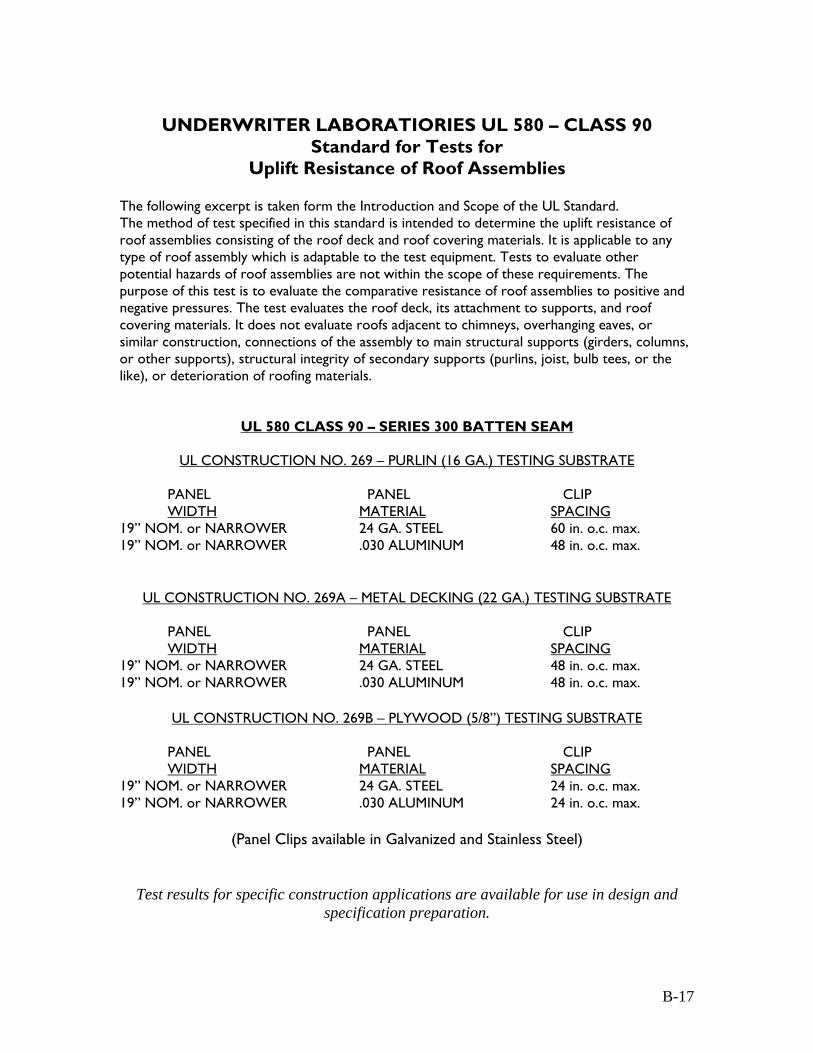
UNDERWRITER LABORATIORIES UL 580 – CLASS 90
Standard for Tests for Uplift Resistance of Roof Assemblies
The following excerpt is taken form the Introduction and Scope of the UL Standard. The method of test specified in this standard is intended to determine the uplift resistance of roof assemblies consisting of the roof deck and roof covering materials. It is applicable to any type of roof assembly which is adaptable to the test equipment. Tests to evaluate other potential hazards of roof assemblies are not within the scope of these requirements. The purpose of this test is to evaluate the comparative resistance of roof assemblies to positive and negative pressures. The test evaluates the roof deck, its attachment to supports, and roof covering materials. It does not evaluate roofs adjacent to chimneys, overhanging eaves, or similar construction, connections of the assembly to main structural supports (girders, columns, or other supports), structural integrity of secondary supports (purlins, joist, bulb tees, or the like), or deterioration of roofing materials.
UL 580 CLASS 90 – SERIES 300 BATTEN SEAM
UL CONSTRUCTION NO. 269 – PURLIN (16 GA.) TESTING SUBSTRATE
PANEL PANEL CLIP WIDTH MATERIAL SPACING
19” NOM. or NARROWER 24 GA. STEEL 60 in. o.c. max. 19” NOM. or NARROWER .030 ALUMINUM 48 in. o.c. max.
UL CONSTRUCTION NO. 269A – METAL DECKING (22 GA.) TESTING SUBSTRATE
PANEL PANEL CLIP WIDTH MATERIAL SPACING
19” NOM. or NARROWER 24 GA. STEEL 48 in. o.c. max. 19” NOM. or NARROWER .030 ALUMINUM 48 in. o.c. max.
UL CONSTRUCTION NO. 269B – PLYWOOD (5/8”) TESTING SUBSTRATE
PANEL PANEL CLIP WIDTH MATERIAL SPACING
19” NOM. or NARROWER 24 GA. STEEL 24 in. o.c. max. 19” NOM. or NARROWER .030 ALUMINUM 24 in. o.c. max.
(Panel Clips available in Galvanized and Stainless Steel)
Test results for specific construction applications are available for use in design and specification preparation.
B-17
UNDERWRITER LABORATIORIES
UL 790 TESTS FOR FIRE RESISTANCE OF ROOF COVERING MATERIALS
Series 300 Standing Seam & Batten Seam
The following is an excerpt for the UL 790 Foreword and Introduction. Foreword This Standard contains a description of the basic test method(s) for evaluating products covered by Underwriters Laboratories Inc. (UL) under its Follow-Up Service for this category within the limitations in the Standard. This test method(s) is based upon sound engineering principles, research, records of tests and field experience, and an appreciation of the problems of manufacture, installation, and use derived form consultation with and information obtained form manufacturers, users, inspection authorities, and others having specialized experience. It is subject to revision as further experience and investigation may show is necessary or desirable. Introduction These requirements cover the performance of roof covering material exposed to fire conditions, and are intended to indicate the fire-resistance characteristics of roof coverings when exposed to fire origination form sources outside a building on which the coverings are installed. They are applicable to roof coverings intended for installation on ether combustible or noncombustible decks when the roof coverings are applied as intended. A combustible deck is formed of wood (sheathing boards or plywood). A noncombustible deck is formed of metal, concrete, or poured gypsum. Class A roof coverings are effective against severe fire test exposures. Under such exposures, roof coverings of this class are not readily flammable, afford a fairly high degree of fire protection to the roof deck, do not slip from position, and are not expected to produce flying brands.
Series 300 Standing Seam & Batten Seam
The complete product line has the UL790 Roof Covering Fire Resistance. UL790 – Class A
See Underwriters Laboratories “Roofing Materials & Systems” listings and classifications manual for complete roofing assembly combinations and descriptions for product applications.
B-18
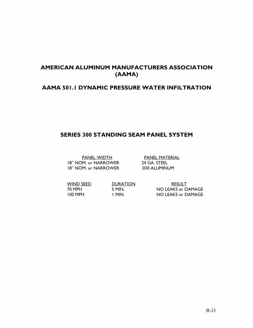
AMERICAN ALUMINUM MANUFACTURERS ASSOCIATION (AAMA)
AAMA 501.1 DYNAMIC PRESSURE WATER INFILTRATION
SERIES 300 STANDING SEAM PANEL SYSTEM
PANEL WIDTH PANEL MATERIAL
18” NOM. or NARROWER 24 GA. STEEL 18” NOM. or NARROWER .030 ALUMINUM WIND SEED DURATION RESULT 70 MPH 5 MIN. NO LEAKS or DAMAGE
100 MPH 1 MIN. NO LEAKS or DAMAGE
B-21
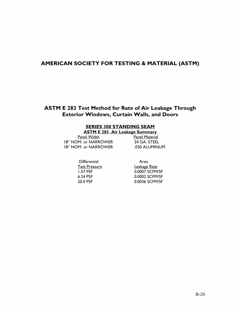
AMERICAN SOCIETY FOR TESTING & MATERIAL (ASTM)
ASTM E 283 Test Method for Rate of Air Leakage Through Exterior Windows, Curtain Walls, and Doors
SERIES 300 STANDING SEAM
ASTM E 283 Air Leakage Summary Panel Width Panel Material
18” NOM. or NARROWER 24 GA. STEEL 18” NOM. or NARROWER .030 ALUMINUM
Differential Area Test Pressure Leakage Rate 1.57 PSF 0.0007 SCFM/SF
6.24 PSF 0.0002 SCFM/SF 20.0 PSF 0.0036 SCFM/SF
B-20
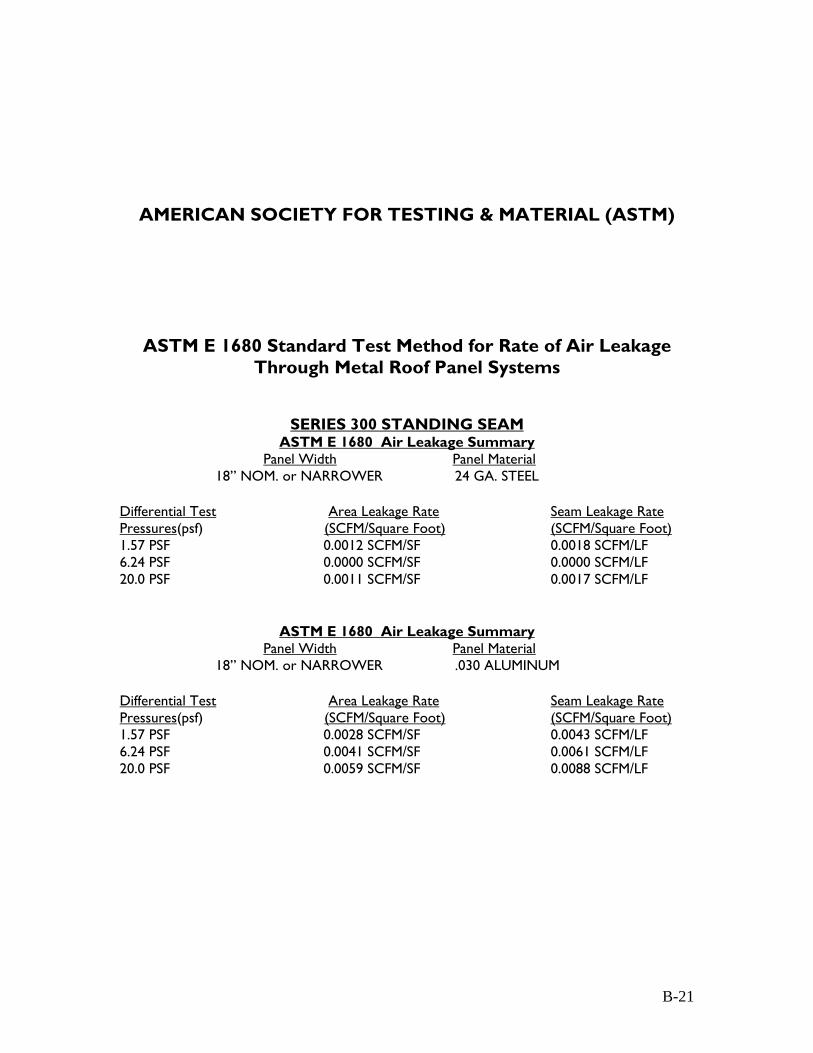
AMERICAN SOCIETY FOR TESTING & MATERIAL (ASTM)
ASTM E 1680 Standard Test Method for Rate of Air Leakage
Through Metal Roof Panel Systems
SERIES 300 STANDING SEAM ASTM E 1680 Air Leakage Summary
Panel Width Panel Material 18” NOM. or NARROWER 24 GA. STEEL
Differential Test Area Leakage Rate Seam Leakage Rate Pressures(psf) (SCFM/Square Foot) (SCFM/Square Foot) 1.57 PSF 0.0012 SCFM/SF 0.0018 SCFM/LF 6.24 PSF 0.0000 SCFM/SF 0.0000 SCFM/LF 20.0 PSF 0.0011 SCFM/SF 0.0017 SCFM/LF
ASTM E 1680 Air Leakage Summary Panel Width Panel Material
18” NOM. or NARROWER .030 ALUMINUM Differential Test Area Leakage Rate Seam Leakage Rate Pressures(psf) (SCFM/Square Foot) (SCFM/Square Foot) 1.57 PSF 0.0028 SCFM/SF 0.0043 SCFM/LF 6.24 PSF 0.0041 SCFM/SF 0.0061 SCFM/LF 20.0 PSF 0.0059 SCFM/SF 0.0088 SCFM/LF
B-21
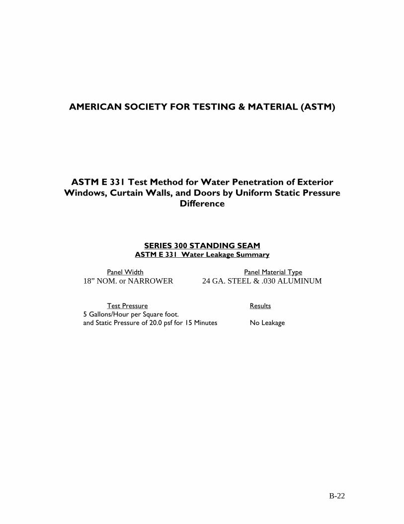
AMERICAN SOCIETY FOR TESTING & MATERIAL (ASTM)
ASTM E 331 Test Method for Water Penetration of Exterior Windows, Curtain Walls, and Doors by Uniform Static Pressure
Difference
SERIES 300 STANDING SEAM ASTM E 331 Water Leakage Summary
Panel Width Panel Material Type
18” NOM. or NARROWER 24 GA. STEEL & .030 ALUMINUM Test Pressure Results
5 Gallons/Hour per Square foot. and Static Pressure of 20.0 psf for 15 Minutes No Leakage
B-22

AMERICAN SOCIETY FOR TESTING & MATERIAL (ASTM)
ASTM E 1646 Standard Test Method for Water Penetration of Exterior Metal Roof Panel Systems by Uniform Static Air
Pressure Difference
SERIES 300 STANDING SEAM ASTM E 1646 Water Penetration Summary
Panel Width Panel Material Type
18” NOM. or NARROWER 24 GA. STEEL & .030 ALUMINUM
Test Pressure Results 5 Gallons/Hour per Square foot. and Static Pressure of 20.0 psf for 15 Minutes No Leakage
B-23
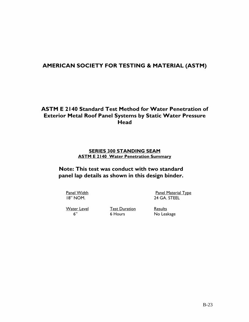
AMERICAN SOCIETY FOR TESTING & MATERIAL (ASTM)
ASTM E 2140 Standard Test Method for Water Penetration of Exterior Metal Roof Panel Systems by Static Water Pressure
Head
SERIES 300 STANDING SEAM ASTM E 2140 Water Penetration Summary
Note: This test was conduct with two standard panel lap details as shown in this design binder.
Panel Width Panel Material Type 18” NOM. 24 GA. STEEL
Water Level Test Duration Results
6” 6 Hours No Leakage
B-23
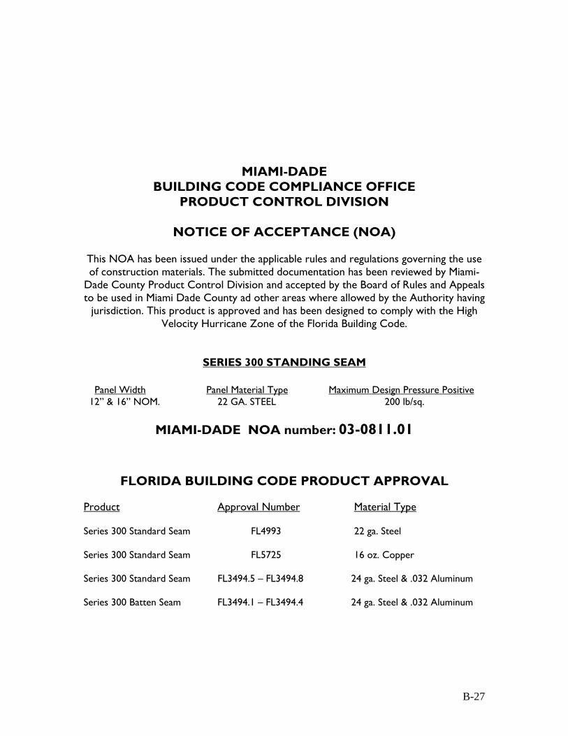
B-27
MIAMI-DADE BUILDING CODE COMPLIANCE OFFICE
PRODUCT CONTROL DIVISION
NOTICE OF ACCEPTANCE (NOA)
This NOA has been issued under the applicable rules and regulations governing the use of construction materials. The submitted documentation has been reviewed by Miami-
Dade County Product Control Division and accepted by the Board of Rules and Appeals to be used in Miami Dade County ad other areas where allowed by the Authority having
jurisdiction. This product is approved and has been designed to comply with the High Velocity Hurricane Zone of the Florida Building Code.
SERIES 300 STANDING SEAM
Panel Width Panel Material Type Maximum Design Pressure Positive 12” & 16” NOM. 22 GA. STEEL 200 lb/sq.
MIAMI-DADE NOA number: 03-0811.01
FLORIDA BUILDING CODE PRODUCT APPROVAL
Product Approval Number Material Type Series 300 Standard Seam FL4993 22 ga. Steel Series 300 Standard Seam FL5725 16 oz. Copper Series 300 Standard Seam FL3494.5 – FL3494.8 24 ga. Steel & .032 Aluminum Series 300 Batten Seam FL3494.1 – FL3494.4 24 ga. Steel & .032 Aluminum

FLORIDA BUILDING CODE - Section 1507.5 SERIES 300 STANDING SEAM - SUMMARY REPORT
TAS 100-95 Test Procedure for Wind and Wind Driven Rain
Resistance of Discontinuous Roof
Panel Width Panel Material Type 12” NOM. 22 GA. STEEL
Air Velocity Simulated Rainfall Test Duration Results 35 mph to 110 mph 8.8 in/hr 90 minutes No Leakage
Summary Observations: No panel movement or water infiltration on the underside of the deck was observed during the test.
TAS 114-95.1 Appendix G: Test Procedure for Susceptibility to
Leakage for Roof System Assemblies
Panel Width Panel Material Type 12” NOM. 22 GA. Steel
Chamber Size Water Depth Test Duration Results 10’ x 10’ 6” 168 Hours No Leakage
Summary Observations: No panel movement or water infiltration on the
underside of the deck was observed during the test.
TAS 201-95.1 Impact Test Procedures / TAS 203-95.1 Criteria for Testing Products Subject to Cyclic Wind Pressure Loading
Panel Width Panel Material Type 16” NOM. 24 GA. Steel / .030 Aluminum
Chamber Size Substrate Assemblies Testing Standard 80” x 192” Metal Decking / Purlin SBCCI – SSTD-12-99 TAS 201- 95.1 Impact Test Procedures Results = No Rupture of Test Specimen TAS 203- 95.1 Cyclic Wind Pressure Loading Test Results = Positive and Negative Pressure Loads up to 100 lbs per sq. ft.
B-28
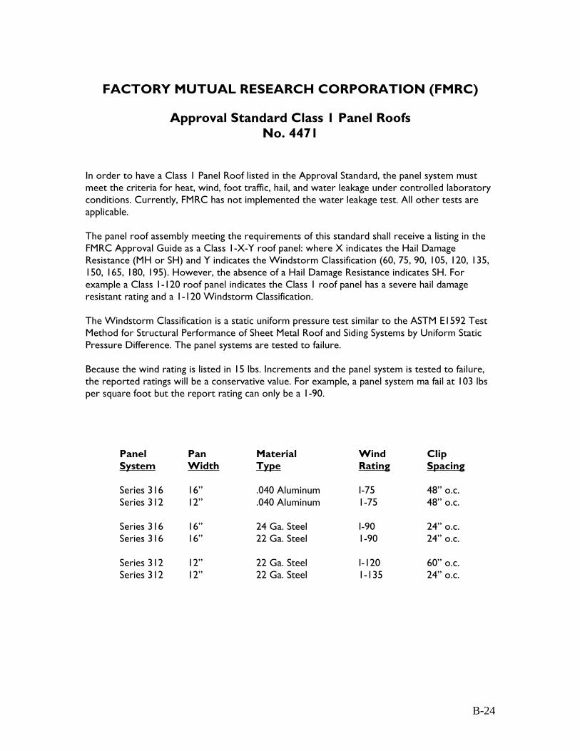
FACTORY MUTUAL RESEARCH CORPORATION (FMRC)
Approval Standard Class 1 Panel Roofs
No. 4471
In order to have a Class 1 Panel Roof listed in the Approval Standard, the panel system must meet the criteria for heat, wind, foot traffic, hail, and water leakage under controlled laboratory conditions. Currently, FMRC has not implemented the water leakage test. All other tests are applicable. The panel roof assembly meeting the requirements of this standard shall receive a listing in the FMRC Approval Guide as a Class 1-X-Y roof panel: where X indicates the Hail Damage Resistance (MH or SH) and Y indicates the Windstorm Classification (60, 75, 90, 105, 120, 135, 150, 165, 180, 195). However, the absence of a Hail Damage Resistance indicates SH. For example a Class 1-120 roof panel indicates the Class 1 roof panel has a severe hail damage resistant rating and a 1-120 Windstorm Classification. The Windstorm Classification is a static uniform pressure test similar to the ASTM E1592 Test Method for Structural Performance of Sheet Metal Roof and Siding Systems by Uniform Static Pressure Difference. The panel systems are tested to failure. Because the wind rating is listed in 15 lbs. Increments and the panel system is tested to failure, the reported ratings will be a conservative value. For example, a panel system ma fail at 103 lbs per square foot but the report rating can only be a 1-90.
Panel Pan Material Wind Clip System Width Type Rating Spacing Series 316 16” .040 Aluminum I-75 48” o.c. Series 312 12” .040 Aluminum 1-75 48” o.c. Series 316 16” 24 Ga. Steel I-90 24” o.c. Series 316 16” 22 Ga. Steel 1-90 24” o.c. Series 312 12” 22 Ga. Steel I-120 60” o.c. Series 312 12” 22 Ga. Steel 1-135 24” o.c.
B-24

Product Guide: United Zinc® Material for Architectural Applications
www.imetco.com | (800) 646-3826 Page 1
© 2010 Innovative Metals Company, Inc.
Product GuideNatural Material for Roofing Systems, Wall Cladding,
and Fascia & Coping Products Used in Architectural Applications

www.imetco.com | (800) 646-3826Page 2
© 2010 Innovative Metals Company, Inc.
www.imetco.com | (800) 646-3826 Page 2
Blank Text
Product Guide: United Zinc® Material for Architectural Applications
www.imetco.com | (800) 646-3826 Page 3
© 2010 Innovative Metals Company, Inc.
ContentsAbout United Zinc .................................................................................................................... 4The Only Domestic Architectural Zinc - Processed and Formed in AmericaArchitectural Building Products by IMETCOProcessing of Zinc Strip by Jarden Zinc
Physical Properties ................................................................................................................... 5Alloy 710Physical and Mechanical PropertiesBackside coating Thermal Movement Self-healing Material compatibility
Design Considerations ............................................................................................................. 8FinishesMemory Ventilation Roof SlopeThe Natural Patina Process and Preweathered Finishes
Material Handling and Installation Guidelines ....................................................................... 9Temperature ConsiderationsPackagingSoldering HandlingField Storage Construction Dust and DebrisProtective FilmCleaningCaulks and Sealants
Products Available in United Zinc .......................................................................................... 11Series 300® Symmetrical Seam Metal RoofTwinLok Mechanically Seamed Metal RoofDLSS Architectural Metal RoofLatitude™ Wall Panel SystemsFW Metal Wall Panel SystemsPermWall Flush Metal Wall SystemPerformaEdge and EZ Edge Fascia & Coping
United Zinc and Sustainability .............................................................................................. 15LEEDEnvironmental ConsiderationsDurability/lifespanRecycled contentRecyclabilityEnergy demand (production)Run-off and Fungal Resistance

Product Guide: United Zinc® Material for Architectural Applications
www.imetco.com | (800) 646-3826Page 4
© 2010 Innovative Metals Company, Inc.
About United ZincThe Only Domestic Architectural Zinc - Processed and Formed in AmericaSince the early 19th century, zinc has remained a preferred roofing material throughout the world. Due to the material’s natural beauty, sustainability and longevity, its popularity in the United States continues to grow.
Now United Zinc, the only domestically produced zinc available to the construction industry in the United States, is available exclusively from IMETCO.
United Zinc is timeless, durable, versatile and environmentally responsible. It is pre-treated for immediate aesthetic appeal and continues to develop is distinctive patina as it ages, which creates a durable, corrosion-resistant surface making United Zinc a long-lasting material suitable for most climates. It resists mold, mildew and fungus, but its runoff is “clean” and will not harm desirable vegetation like other exotic metals can. In addition to being non-corrosive and environmentally-friendly, United Zinc is virtually maintenance free; its self-healing nature can even make scratches disappear over time. In terms of recyclability, United Zinc not only has extremely high recycled content (more than 30% comes from recycled or secondary zinc), but it is also 100% recyclable and has a high scrap value.
United Zinc’s versatility makes it an ideal material for a variety of design styles and applications.
Industry Leaders IMETCO and Jarden Zinc Partner to Bring You United ZincBy leveraging the unique strengths of these partners, we are able to provide the highest quality domestic zinc architectural products with shorter lead-times while maintaining environmentally responsible manufacturing practices.
Architectural Building Products by IMETCOIMETCO®, a recognized leader in the metal roofing industry for decades, offers a full range of high-quality performance-inspired exterior metal building products, including roofing systems, wall panels, fascia and coping, and a variety of accessories. IMETCO continues to produce its signature products while developing and introducing new products and services in response to the needs of the customers it proudly serves.
With exceptional service as its core value, IMETCO has experienced continuous and exponential growth since its inception. Its staff comprises experts in metal roofing, metal design, engineering, testing, code compliance, manufacturing, and more. Special manufacturing capabilities, such as curving, tapering, and field forming further distinguish IMETCO from other manufacturers. An in-house engineering team provides project support and produces custom project-specific shop drawings. Project managers work diligently to streamline the procurement and delivery of materials, and value-added production services help accommodate even the most aggressive installation schedules.
What truly sets IMETCO apart is the level of service and support provided to each and every customer, for at IMETCO, your satisfaction is our only measure of success.
Processing of Zinc Strip by Jarden ZincJarden Zinc Products, a subsidiary of the Jarden Corporation, is the only producer of solid zinc strip for architectural applications in North America. At its 350,000-square-foot manufacturing facility located in Greeneville, Tennessee, Jarden casts and rolls 120,000 metric tons of finished solid zinc strip each year. Jarden uses only 99.995% pure special high-grade zinc with copper, titanium and other metals to craft alloys that are continuously cast and rolled into solid zinc strip in a variety of gauges that meets all EN 988 standards.
With the most stringent quality control standards in place, Jarden continuously monitors and tests to ensure a consistently produced high-quality zinc product that is used throughout the world for a variety of applications including coinage, automotive, electronic, cathodic protection, and architectural building materials.
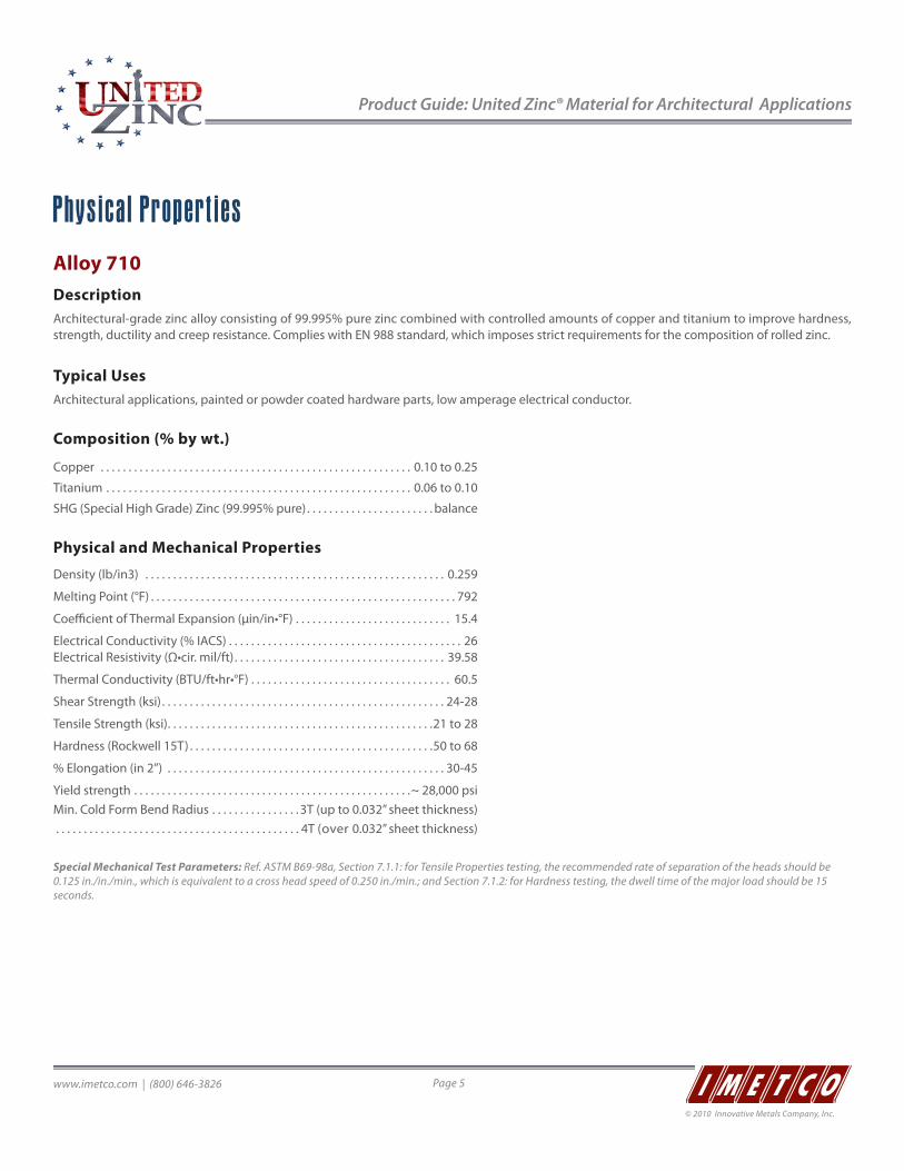
Product Guide: United Zinc® Material for Architectural Applications
www.imetco.com | (800) 646-3826 Page 5
© 2010 Innovative Metals Company, Inc.
Physical PropertiesAlloy 710Description Architectural-grade zinc alloy consisting of 99.995% pure zinc combined with controlled amounts of copper and titanium to improve hardness, strength, ductility and creep resistance. Complies with EN 988 standard, which imposes strict requirements for the composition of rolled zinc.
Typical UsesArchitectural applications, painted or powder coated hardware parts, low amperage electrical conductor.
Composition (% by wt.)
Copper . . . . . . . . . . . . . . . . . . . . . . . . . . . . . . . . . . . . . . . . . . . . . . . . . . . . . . . . 0.10 to 0.25
Titanium . . . . . . . . . . . . . . . . . . . . . . . . . . . . . . . . . . . . . . . . . . . . . . . . . . . . . . . 0.06 to 0.10
SHG (Special High Grade) Zinc (99.995% pure) . . . . . . . . . . . . . . . . . . . . . . . balance
Physical and Mechanical Properties
Density (lb/in3) . . . . . . . . . . . . . . . . . . . . . . . . . . . . . . . . . . . . . . . . . . . . . . . . . . . . . . 0.259
Melting Point (°F) . . . . . . . . . . . . . . . . . . . . . . . . . . . . . . . . . . . . . . . . . . . . . . . . . . . . . . . 792
Coefficient of Thermal Expansion (μin/in•°F) . . . . . . . . . . . . . . . . . . . . . . . . . . . . 15.4
Electrical Conductivity (% IACS) . . . . . . . . . . . . . . . . . . . . . . . . . . . . . . . . . . . . . . . . . . 26 Electrical Resistivity (Ω•cir. mil/ft). . . . . . . . . . . . . . . . . . . . . . . . . . . . . . . . . . . . . . 39.58
Thermal Conductivity (BTU/ft•hr•°F) . . . . . . . . . . . . . . . . . . . . . . . . . . . . . . . . . . . . 60.5
Shear Strength (ksi) . . . . . . . . . . . . . . . . . . . . . . . . . . . . . . . . . . . . . . . . . . . . . . . . . . . 24-28
Tensile Strength (ksi). . . . . . . . . . . . . . . . . . . . . . . . . . . . . . . . . . . . . . . . . . . . . . . .21 to 28
Hardness (Rockwell 15T) . . . . . . . . . . . . . . . . . . . . . . . . . . . . . . . . . . . . . . . . . . . .50 to 68
% Elongation (in 2”) . . . . . . . . . . . . . . . . . . . . . . . . . . . . . . . . . . . . . . . . . . . . . . . . . . 30-45
Yield strength . . . . . . . . . . . . . . . . . . . . . . . . . . . . . . . . . . . . . . . . . . . . . . . . . .~ 28,000 psiMin. Cold Form Bend Radius . . . . . . . . . . . . . . . . 3T (up to 0.032” sheet thickness) . . . . . . . . . . . . . . . . . . . . . . . . . . . . . . . . . . . . . . . . . . . . 4T (over 0.032” sheet thickness)
Special Mechanical Test Parameters: Ref. ASTM B69-98a, Section 7.1.1: for Tensile Properties testing, the recommended rate of separation of the heads should be 0.125 in./in./min., which is equivalent to a cross head speed of 0.250 in./min.; and Section 7.1.2: for Hardness testing, the dwell time of the major load should be 15 seconds.
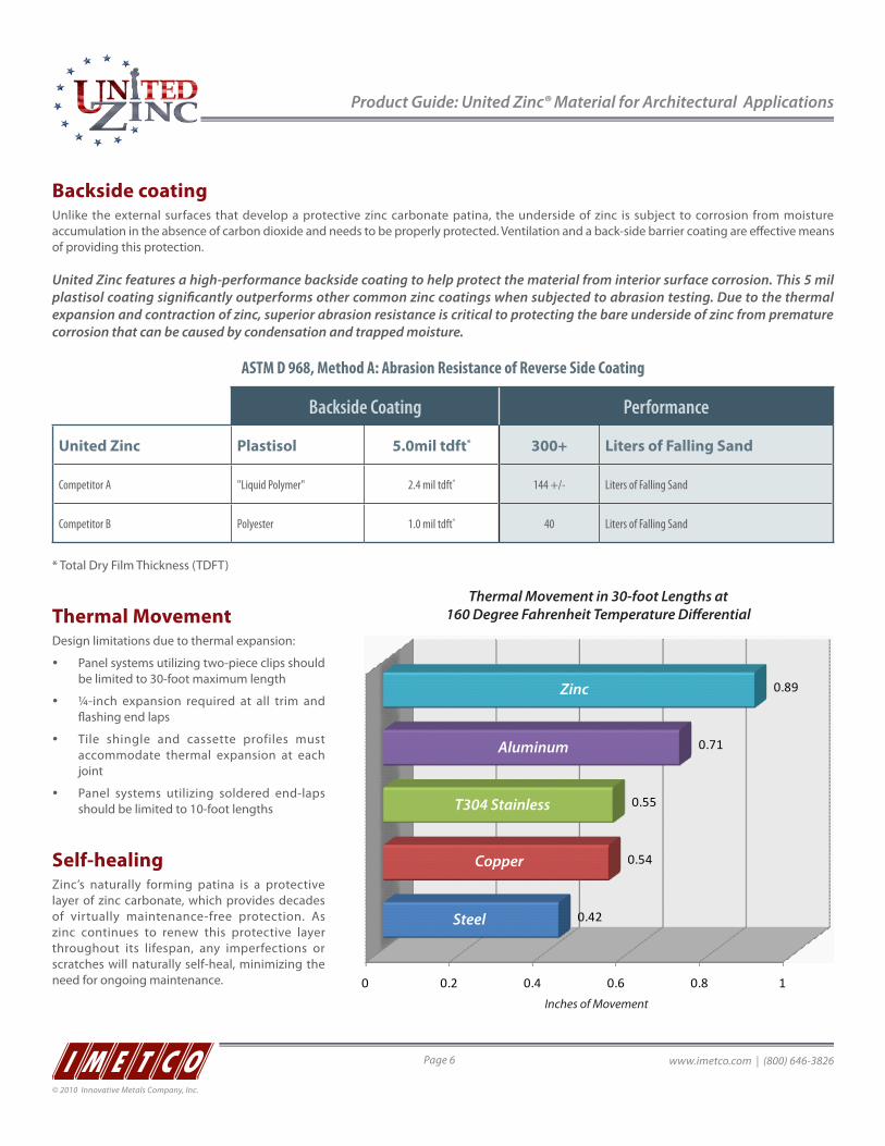
Product Guide: United Zinc® Material for Architectural Applications
www.imetco.com | (800) 646-3826Page 6
© 2010 Innovative Metals Company, Inc.
Backside coating Unlike the external surfaces that develop a protective zinc carbonate patina, the underside of zinc is subject to corrosion from moisture accumulation in the absence of carbon dioxide and needs to be properly protected. Ventilation and a back-side barrier coating are effective means of providing this protection.
United Zinc features a high-performance backside coating to help protect the material from interior surface corrosion. This 5 mil plastisol coating significantly outperforms other common zinc coatings when subjected to abrasion testing. Due to the thermal expansion and contraction of zinc, superior abrasion resistance is critical to protecting the bare underside of zinc from premature corrosion that can be caused by condensation and trapped moisture.
ASTM D 968, Method A: Abrasion Resistance of Reverse Side Coating
Backside Coating Performance
United Zinc Plastisol 5.0mil tdft* 300+ Liters of Falling Sand
Competitor A "Liquid Polymer" 2.4 mil tdft* 144 +/- Liters of Falling Sand
Competitor B Polyester 1.0 mil tdft* 40 Liters of Falling Sand
* Total Dry Film Thickness (TDFT)
Thermal Movement Design limitations due to thermal expansion:
y Panel systems utilizing two-piece clips should be limited to 30-foot maximum length
y ¼-inch expansion required at all trim and flashing end laps
y Tile shingle and cassette profiles must accommodate thermal expansion at each joint
y Panel systems utilizing soldered end-laps should be limited to 10-foot lengths
Self-healing Zinc’s naturally forming patina is a protective layer of zinc carbonate, which provides decades of virtually maintenance-free protection. As zinc continues to renew this protective layer throughout its lifespan, any imperfections or scratches will naturally self-heal, minimizing the need for ongoing maintenance. 0 0.2 0.4 0.6 0.8 1
0.42
0.54
0.55
0.71
0.89Zinc
Aluminum
T304 Stainless
Copper
Steel
Thermal Movement in 30-foot Lengths at 160 Degree Fahrenheit Temperature Di�erential
Inches of Movement

Product Guide: United Zinc® Material for Architectural Applications
www.imetco.com | (800) 646-3826 Page 7
© 2010 Innovative Metals Company, Inc.
Material compatibilitySome materials can have detrimental effects on the appearance and integrity of zinc. Acidic products and products that can generate a galvanic reaction must not be used with zinc.
CORRODED END
(ANODIC OR LEAST NOBLE)
Magnesium
Zinc
Galvanized Steel
Aluminum
Mild Steel (1018), Wrought Iron
Cast Iron, Low Alloy High Strength Steel
Lead
Tin, Tin-Lead Solder
430 Stainless Steel (active)
302, 304, 410 Stainless Steel (active)
316, 317 Stainless Steel (active)
Brass and Bronze
Copper
Nickel, Monel, Titanium
Silver
Graphite
Gold
Platinum
PROTECTED END (CATHODIC OR MOST
NOBLE)
Electrical Potential between Zinc and other Metals
y For exterior environments (exposed to weather), there should not be more than 0.15 V electrical potential in the Anodic Index
y For exterior environments (concealed spaces) and interior spaces (non-temperature or-humidity controlled), typically there should not be more than 0.25 V electrical potential
y For interior controlled environments, 0.50 V electrical potential can be tolerated
Compatibility with Wood and PlywoodZinc can be used with certain woods, such as poplar, spruce, and pine. More acidic woods (such as chestnut, Douglas Fir, oak, larch, birch and red, white and yellow cedar), should be avoided. Zinc should not come in direct contact with plywood or chipboard, as these products can contain acidic timber types, tannins, or phenolic adhesives, and do not absorb humidity or allow ventilation. All of these factors increase the risk of corrosion. If these materials are used, exterior quality treated plywood is recommended, and the zinc should be protected by a plastisol backside coating (standard on United Zinc).
Compatibility with Bituminous FeltZinc should not come in direct contact with bituminous felt due to the risk of water retention in the felt, which increases the risk of corrosion. If felt is used, the zinc should be protected by a plastisol backside coating that can withstand abrasion due to thermal movement (standard on United Zinc).
Compatibility with ConcreteZinc should not come in direct contact with concrete or reinforced concrete. If concrete is used, the zinc should be properly ventilated and protected by a plastisol backside coating (standard on United Zinc).
Run-OffRun-off from non compatible products onto zinc must be avoided. Run off from a copper surface to a zinc surface must be avoided under all circumstances. In general, water should not be allowed to run from a higher potential metal to a lower one.
Compatibility with Other Metals
0 0.2 0.4 0.6 0.8 1
0.05 V
0.35 V
0.4 V
0.55 V
0.75 V
0.9 VZinc - Copper
Zinc - Aluminum
Zinc - Iron
Zinc - Lead
Zinc - T3xx Stainless (active)
Zinc - Galvanized Steel

Product Guide: United Zinc® Material for Architectural Applications
www.imetco.com | (800) 646-3826Page 8
© 2010 Innovative Metals Company, Inc.
Design ConsiderationsThe versatility of Solid Zinc Strip makes it ideal for exterior and interior architectural applications. Zinc’s cool gray patina and natural surface blends beautifully with most building materials and surroundings, both in contemporary and traditional settings and environments.
Finishes y Glacier Gray
y Glacier Gray TextureMatte™
y Onyx Black
Memory Due to the mechanical nature of solid zinc strip, building products that rely upon compression fitting may not maintain tolerances and are not recommended. It is imperative that the profiles selected are mechanically seamed or otherwise engineered to stay in place.
Ventilation United Zinc features a high-performance plastisol back coating to protect the material from interior surface corrosion. While a degree of ventilation is still recommended, IMETCO’s United Zinc panels can typically be installed in the same manner as other metal roofing and wall systems. Commercially available zinc with no backside coating should be avoided, since the probability for corrosion is increased.
Contact your IMETCO representative for more information.
Roof SlopeTo make sure the zinc is not subjected to ponding water, a minimum slope of 1:12 is recommended. The minimum slope required for specific roofing products varies; refer to the individual product’s design guidelines for more information on minimum roof slopes.
The Natural Patina Process and Preweathered FinishesZinc’s naturally forming cool gray patina provides ageless beauty and life-long protection. The natural patina is a layer of zinc-hydroxy carbonate, which forms when zinc comes in contact with water and carbon dioxide from the atmosphere. Typically, the patina begins to form in two to five years (except in arid climates where it may evolve over a longer period of time), and maintains a uniform color throughout the zinc’s lifespan.
United Zinc’s preweathered Glacier Gray finish immediately provides the designer with the look of a naturally appearing weathered patina. The cool gray tones utilized with the Glacier Gray finishing process most accurately resemble the innate patina appearance that all zinc products will, over time, inherently achieve.
The TextureMatte™ finish provides a very fine and subtle surface quality, which is achieved through a roller-texturing process on the architectural zinc strip. TextureMatte material exhibits a matte finish luster and the appearance of improved flatness.
The United Zinc preweathered Onyx Black finish is achieved by a multi-step process which includes chemically reactive processes such as immersion in reactive baths, passivation treatments, and solid pigmentation application. The Onyx Black finish can be expected to retain its uniform dark coloration for decades.
Efflorescence is a normal weathering condition that sometimes occurs as a typical and generally temporary stage of the natural patina process, and is not a defect or cause for rejection.
While properly designed zinc cladding systems can provide many decades of successful performance in virtually all environments and geographical regions, please consult with the United Zinc technical support team to evaluate each specific application. In some infrequent and specific climatic conditions, other base metal materials may be recommended for certain specific cladding system applications.
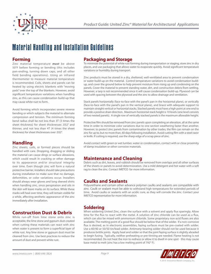
Product Guide: United Zinc® Material for Architectural Applications
www.imetco.com | (800) 646-3826 Page 9
© 2010 Innovative Metals Company, Inc.
Material Handling and Installation GuidelinesFormingZinc material temperature must be above 50°F before forming or bending (this includes pan-ending, turning down caps, and all other field bending operations). Using an infrared thermometer to measure material temperature is recommended. Coils, sheets and panels can be heated by using electric blankets with “moving pads” over the top of the blankets. However, avoid significant temperature variations when handling zinc, as this can cause condensation build-up that may cause white rust to form.
Avoid forming which incorporates severe reverse bending or which subjects the material to alternate compression and tension. The minimum forming bend radius shall be not less than 3T (3 times the sheet thickness) for sheet thicknesses .032” and thinner, and not less than 4T (4 times the sheet thickness) for sheet thicknesses over .032”.
HandlingZinc sheets, coils, or formed pieces should be handled with care. Dropping, dragging or sliding the material can cause dings or surface abrasions, which could result in cracking or other damage to its appearance and/or structural integrity over time. Even though zinc will form a natural protective barrier, installers should take precautions during installation to make sure that no damage, deformities, or color variations occur. Installers should always wear gloves and long sleeved shirts when handling zinc, since perspiration and oils in the skin will leave marks on its surface. While these marks will heal over time, they will remain visible for a while, affecting aesthetic appearance of the zinc immediately after installation.
Construction Dust & DebrisWhile run-off from lime stone onto zinc is acceptable, the lime stone and gypsum dust created when cutting these materials can react with zinc when water is present to form a superficial layer of white rust. Any lime stone or gypsum dust must be cleaned from zinc. Use best practices to reduce the amount of dust and prevent white rust.
Packaging and StorageTo minimize the potential of white rust forming during transportation or staging, store zinc in dry places, and use packaging that allows water to evaporate quickly. Avoid significant temperature variations or humidity during transport.
Zinc products must be stored in a dry, sheltered, well-ventilated area to prevent condensation or water build-up on the material. Control temperature variations to avoid condensation build-up, and cover the ground below to help prevent moisture from rising up and condensing on the panels. Cover the material to prevent standing water, dirt, and construction debris from settling. However, a tarp is not recommended since it will cause condensation build-up. Plywood can be used with spacing between the plywood and the zinc to allow drainage and ventilation.
Stack panels horizontally (face-to-face with the panel’s pan in the horizontal plane), or vertically (face-to-face with the panel’s pan in the vertical plane), and brace with adequate support to maintain straight vertical or horizontal stacks. Stacked panels must have a high point at one end to provide a positive drain direction. Maximum horizontal stack height is 10 levels (one level consists of two nested panels). A single row of vertically stacked panels is the maximum allowable height.
Protective film should be removed from zinc panels upon completing an elevation, all at the same time in order to minimize color variations due to one section weathering faster than another. However, to protect zinc panels from contamination by other trades, the film can remain on the zinc for up to, but no more than, 60 days following installation. Avoid cutting film with a steel razor or knife. If cutting is required, use the sharp edge of a scrap piece of zinc.
Avoid contact with green or wet lumber, water or condensation, contact with or close proximity of damp insulation or other corrosive materials.
Maintenance and CleaningDebris such as dirt, leaves, and rubbish should be removed from overlaps and all other surfaces of the sheets or panels to avoid determioration. Use a mild detergent and hot water with a soft rag to clean the zinc. Contact IMETCO for more information.
Caulks and SealantsPolyurethane and certain other advance polymer caulks and sealants are compatible with zinc. Caulk or sealant must be able to withstand high temperatures for extended periods of time. Avoid caulks or sealants with an acidic cure, as they will corrode the zinc. Contact your IMETCO representative for more information.
Soldering When soldering United Zinc, clean the surface with a solvent and apply flux sparingly. Allow time for the flux to react with the metal. A solution of zinc chloride can be used as a flux, which can also be mixed with ammonium chloride. Some proprietary non-acid fluxes are also available. The melting point of a good flux should be below that of the solder. If a non-corrosive flux is desired, as in electronic assemblies, faying surfaces must be pre-coated with solder. Use a 60/40 or 50/50 tin/lead solder. Antimony-bearing solder should not be used because it produces brittle joints. Apply heat and solder so that the joint faying surface is slightly abraded to begin fusing. Typically, neither preheating or pre-tinning are needed. Flame heating is not recommended. Do not heat the iron to redness or allow it to dwell in one spot - this may cause base metal to melt (zinc has a low melting point of 792° F).

www.imetco.com | (800) 646-3826Page 10
© 2010 Innovative Metals Company, Inc.
www.imetco.com | (800) 646-3826 Page 10
Blank Text
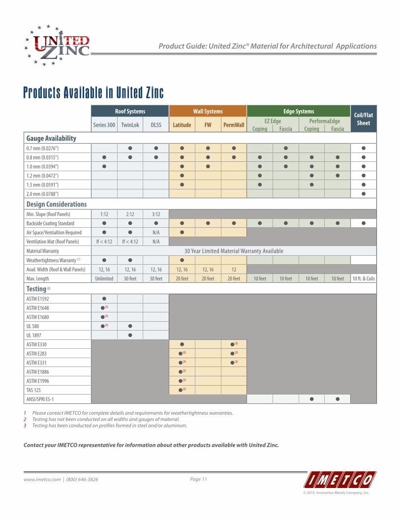
Product Guide: United Zinc® Material for Architectural Applications
www.imetco.com | (800) 646-3826 Page 11
© 2010 Innovative Metals Company, Inc.
Products Available in United ZincRoof Systems Wall Systems Edge Systems Coil/Flat
SheetSeries 300 TwinLok DLSS Latitude FW PermWall EZ Edge PerformaEdgeCoping Fascia Coping Fascia
Gauge Availability0.7 mm (0.0276") � � � � � � �
0.8 mm (0.0315") � � � � � � � � � � �
1.0 mm (0.0394") � � � � � � � �
1.2 mm (0.0472") � � � � �
1.5 mm (0.0591") � � � �
2.0 mm (0.0788") �
Design ConsiderationsMin. Slope (Roof Panels) 1:12 2:12 3:12
Backside Coating Standard � � � � � � � � � � �
Air Space/Ventialtion Required � � N/A �
Ventilation Mat (Roof Panels) If < 4:12 If < 4:12 N/A
Material Warranty 30 Year Limited Material Warranty AvailableWeathertightness Warranty (1) � � �
Avail. Width (Roof & Wall Panels) 12, 16 12, 16 12, 16 12, 16 12, 16 12
Max. Length Unlimited 30 feet 30 feet 20 feet 20 feet 20 feet 10 feet 10 feet 10 feet 10 feet 10 ft. & Coils
Testing (2)
ASTM E1592 �
ASTM E1648 �(3)
ASTM E1680 �(3)
UL 580 �(3) �
UL 1897 �
ASTM E330 � �(3)
ASTM E283 �(3) �(3)
ASTM E331 �(3) �(3)
ASTM E1886 �(3)
ASTM E1996 �(3)
TAS 125 �(3)
ANSI/SPRI ES-1 � �
1 Please contact IMETCO for complete details and requirements for weathertightness warranties.2 Testing has not been conducted on all widths and gauges of material.3 Testing has been conducted on profiles formed in steel and/or aluminum.
Contact your IMETCO representative for information about other products available with United Zinc.
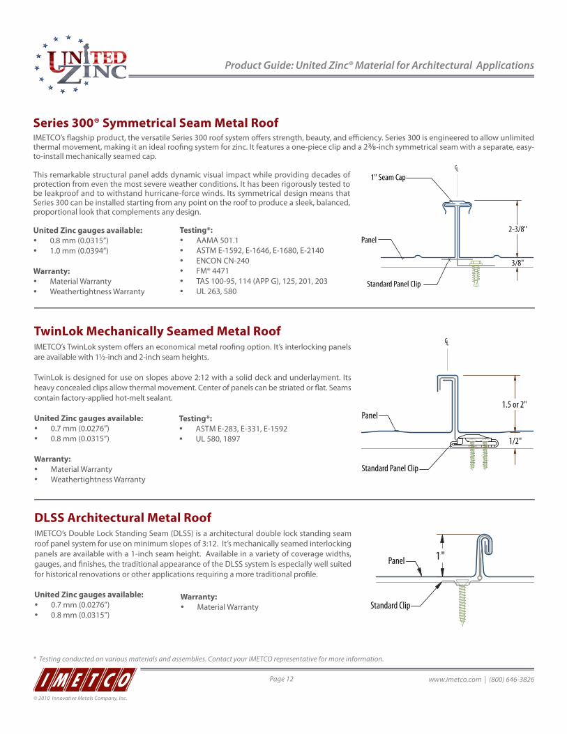
Product Guide: United Zinc® Material for Architectural Applications
www.imetco.com | (800) 646-3826Page 12
© 2010 Innovative Metals Company, Inc.
CL
1/2"
Standard Panel Clip
Panel
2-piece Panel Clip24 Ga. Galvanized Steel
Twin-Loc Seaming Operation
STEP #3STEP #2STEP #1
1/2"
1"
2 7/8"
1 5/16"
1 3/4"
Gable Clip
18 Ga. Stainless Steel18 Ga. Galv. Steel
1.5 or 2"
TwinLok Mechanically Seamed Metal RoofIMETCO’s TwinLok system offers an economical metal roofing option. It’s interlocking panels are available with 1½-inch and 2-inch seam heights.
TwinLok is designed for use on slopes above 2:12 with a solid deck and underlayment. Its heavy concealed clips allow thermal movement. Center of panels can be striated or flat. Seams contain factory-applied hot-melt sealant.
United Zinc gauges available: y 0.7 mm (0.0276”) y 0.8 mm (0.0315”)
Warranty: y Material Warranty y Weathertightness Warranty
DLSS Architectural Metal RoofIMETCO’s Double Lock Standing Seam (DLSS) is a architectural double lock standing seam roof panel system for use on minimum slopes of 3:12. It’s mechanically seamed interlocking panels are available with a 1-inch seam height. Available in a variety of coverage widths, gauges, and finishes, the traditional appearance of the DLSS system is especially well suited for historical renovations or other applications requiring a more traditional profile.
United Zinc gauges available: y 0.7 mm (0.0276”) y 0.8 mm (0.0315”)
Standard Clip
Panel 1"
Series 300® Symmetrical Seam Metal RoofIMETCO’s flagship product, the versatile Series 300 roof system offers strength, beauty, and efficiency. Series 300 is engineered to allow unlimited thermal movement, making it an ideal roofing system for zinc. It features a one-piece clip and a 2⅜-inch symmetrical seam with a separate, easy-to-install mechanically seamed cap.
This remarkable structural panel adds dynamic visual impact while providing decades of protection from even the most severe weather conditions. It has been rigorously tested to be leakproof and to withstand hurricane-force winds. Its symmetrical design means that Series 300 can be installed starting from any point on the roof to produce a sleek, balanced, proportional look that complements any design.
United Zinc gauges available: y 0.8 mm (0.0315”) y 1.0 mm (0.0394”)
Warranty: y Material Warranty y Weathertightness Warranty
Testing*: y AAMA 501.1 y ASTM E-1592, E-1646, E-1680, E-2140 y ENCON CN-240 y FM® 4471 y TAS 100-95, 114 (APP G), 125, 201, 203 y UL 263, 580
LC
2-3/8"
Standard Panel Clip
1" Seam Cap
Panel
3/8"
Testing*: y ASTM E-283, E-331, E-1592 y UL 580, 1897
Warranty: y Material Warranty
* Testing conducted on various materials and assemblies. Contact your IMETCO representative for more information.
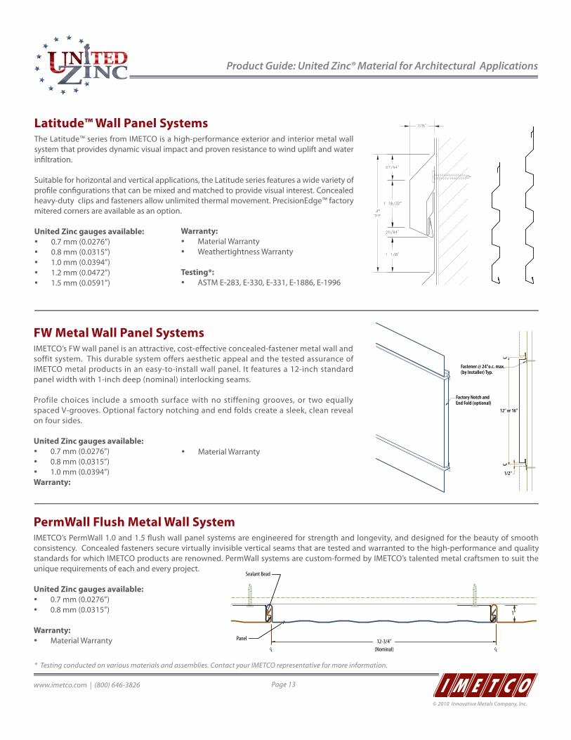
Product Guide: United Zinc® Material for Architectural Applications
www.imetco.com | (800) 646-3826 Page 13
© 2010 Innovative Metals Company, Inc.
Latitude™ Wall Panel SystemsThe Latitude™ series from IMETCO is a high-performance exterior and interior metal wall system that provides dynamic visual impact and proven resistance to wind uplift and water infiltration.
Suitable for horizontal and vertical applications, the Latitude series features a wide variety of profile configurations that can be mixed and matched to provide visual interest. Concealed heavy-duty clips and fasteners allow unlimited thermal movement. PrecisionEdge™ factory mitered corners are available as an option.
United Zinc gauges available: y 0.7 mm (0.0276”) y 0.8 mm (0.0315”) y 1.0 mm (0.0394”) y 1.2 mm (0.0472”) y 1.5 mm (0.0591”)
LW12A-4 LW12A-18F LW12A-18BLW12A-12B
LW16A-4 LW16A-28B LW16A-12BLW16A-18B
LW12A-4 LW12A-18F LW12A-18BLW12A-12B
LW16A-4 LW16A-28B LW16A-12BLW16A-18B
PermWall Flush Metal Wall SystemIMETCO’s PermWall 1.0 and 1.5 flush wall panel systems are engineered for strength and longevity, and designed for the beauty of smooth consistency. Concealed fasteners secure virtually invisible vertical seams that are tested and warranted to the high-performance and quality standards for which IMETCO products are renowned. PermWall systems are custom-formed by IMETCO’s talented metal craftsmen to suit the unique requirements of each and every project.
United Zinc gauges available: y 0.7 mm (0.0276”) y 0.8 mm (0.0315”)
Warranty: y Material Warranty
FW Metal Wall Panel SystemsIMETCO’s FW wall panel is an attractive, cost-effective concealed-fastener metal wall and soffit system. This durable system offers aesthetic appeal and the tested assurance of IMETCO metal products in an easy-to-install wall panel. It features a 12-inch standard panel width with 1-inch deep (nominal) interlocking seams.
Profile choices include a smooth surface with no stiffening grooves, or two equally spaced V-grooves. Optional factory notching and end folds create a sleek, clean reveal on four sides.
United Zinc gauges available: y 0.7 mm (0.0276”) y 0.8 mm (0.0315”) y 1.0 mm (0.0394”)
Warranty:
Fastener @ 24"o.c. max.(by Installer) Typ.
LCLC
Factory Notch andEnd Fold (optional)
12" or 16"
1/2"
Warranty: y Material Warranty y Weathertightness Warranty
Testing*: y ASTM E-283, E-330, E-331, E-1886, E-1996
y Material Warranty
* Testing conducted on various materials and assemblies. Contact your IMETCO representative for more information.
1 2
CL LC(Nominal)12-3/4"
1"
Panel
Sealant Bead
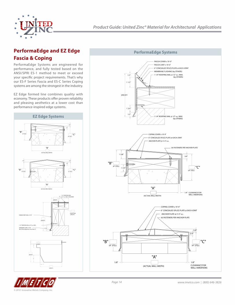
Product Guide: United Zinc® Material for Architectural Applications
www.imetco.com | (800) 646-3826Page 14
© 2010 Innovative Metals Company, Inc.
PerformaEdge and EZ Edge Fascia & CopingPerformaEdge Systems are engineered for performance, and fully tested based on the ANSI/SPRI ES-1 method to meet or exceed your specific project requirements. That’s why our ES-F Series Fascia and ES-C Series Coping systems are among the strongest in the industry.
EZ Edge formed line combines quality with economy. These products offer proven reliability and pleasing aesthetics at a lower cost than performance-inspired edge systems.
(ACTUAL WALL WIDTH)
"A"
"B""C"
(4" STD.)
(4" STD.)
1/4"
3/4"
CLEARANCE FORWALL VARIATIONS
1 3/8"
COPING COVER x 10'-0"
6" CONCEALED SPLICE PLATE @ EACH JOINT
ANCHOR PLATE @ 5'-0" o.c.
(4) FASTENERS PER ANCHOR PLATE
1 3/4"
SPECIFY
1 1/2"
1/2"
1/2"
1 3/4"
FASCIA CANT x 10'-0"
6" CONCEALED SPLICE PLATE @ EACH JOINT
MEMBRANE FLASHING (by OTHERS)
1 1/4" ROOFING NAIL @ 12" o.c. MAX.(by OTHERS)
FASCIA COVER x 10'-0"
1 1/4" ROOFING NAIL @ 12" o.c. MAX.(by OTHERS)
(ACTUAL WALL WIDTH)
"A"
"B" "C"(4" STD.)(4" STD.)
5/8"5/8"
7/8"
(ACTUAL WALL WIDTH)
"A"
"B""C"
(4" STD.)
(4" STD.)
5/8"
7/8"
(SPECIFY)
1"
1" 1"
(SPECIFY)
2"
1"
(ACTUAL WALL WIDTH)
"A"
"B" "C"(4" STD.)(4" STD.)
1/8" CLEARANCE FORWALL VARIATIONS
1/8"
3/4"5/8"
COPING COVER x 10'-0"
6" CONCEALED SPLICE PLATE @ EACH JOINT
ANCHOR PLATE @ 5'-0" o.c.
(4) FASTENERS PER ANCHOR PLATE
EZ Edge Systems
PerformaEdge Systems
(SPECIFY)
1 1/2"
(SPECIFY)
(SPECIFY)Angle/Slope
1 1/4" ROOFING NAIL @ 18" o.c. MAX.
STANDARD CLEAT x 10'-0"
FORMED DRIP EDGE x 10'-0"
1 1/4" ROOFING NAIL
(N/A if Drip Edge Face is less than 2")
@12" o.c. MAX. STAGGERED
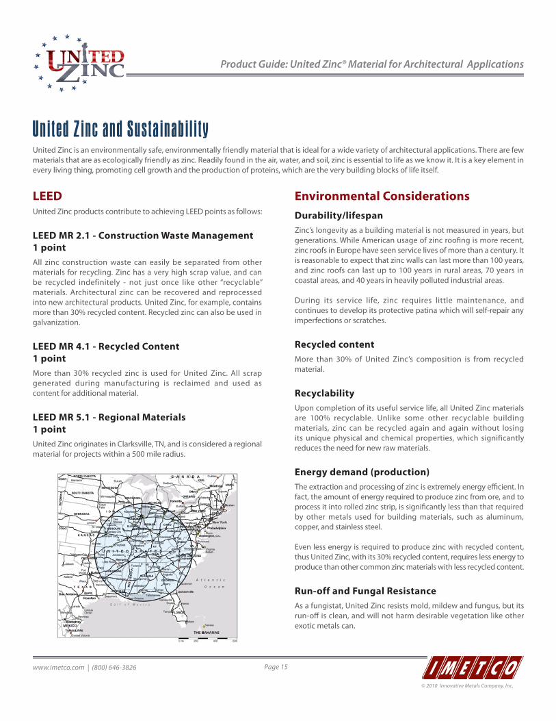
Product Guide: United Zinc® Material for Architectural Applications
www.imetco.com | (800) 646-3826 Page 15
© 2010 Innovative Metals Company, Inc.
United Zinc and SustainabilityUnited Zinc is an environmentally safe, environmentally friendly material that is ideal for a wide variety of architectural applications. There are few materials that are as ecologically friendly as zinc. Readily found in the air, water, and soil, zinc is essential to life as we know it. It is a key element in every living thing, promoting cell growth and the production of proteins, which are the very building blocks of life itself.
LEEDUnited Zinc products contribute to achieving LEED points as follows:
LEED MR 2.1 - Construction Waste Management 1 pointAll zinc construction waste can easily be separated from other materials for recycling. Zinc has a very high scrap value, and can be recycled indefinitely - not just once like other “recyclable” materials. Architectural zinc can be recovered and reprocessed into new architectural products. United Zinc, for example, contains more than 30% recycled content. Recycled zinc can also be used in galvanization.
LEED MR 4.1 - Recycled Content 1 pointMore than 30% recycled zinc is used for United Zinc. All scrap generated during manufacturing is reclaimed and used as content for additional material.
LEED MR 5.1 - Regional Materials 1 pointUnited Zinc originates in Clarksville, TN, and is considered a regional material for projects within a 500 mile radius.
Environmental ConsiderationsDurability/lifespanZinc’s longevity as a building material is not measured in years, but generations. While American usage of zinc roofing is more recent, zinc roofs in Europe have seen service lives of more than a century. It is reasonable to expect that zinc walls can last more than 100 years, and zinc roofs can last up to 100 years in rural areas, 70 years in coastal areas, and 40 years in heavily polluted industrial areas.
During its service life, zinc requires little maintenance, and continues to develop its protective patina which will self-repair any imperfections or scratches.
Recycled contentMore than 30% of United Zinc’s composition is from recycled material.
RecyclabilityUpon completion of its useful service life, all United Zinc materials are 100% recyclable. Unlike some other recyclable building materials, zinc can be recycled again and again without losing its unique physical and chemical properties, which significantly reduces the need for new raw materials.
Energy demand (production)The extraction and processing of zinc is extremely energy efficient. In fact, the amount of energy required to produce zinc from ore, and to process it into rolled zinc strip, is significantly less than that required by other metals used for building materials, such as aluminum, copper, and stainless steel.
Even less energy is required to produce zinc with recycled content, thus United Zinc, with its 30% recycled content, requires less energy to produce than other common zinc materials with less recycled content.
Run-off and Fungal Resistance As a fungistat, United Zinc resists mold, mildew and fungus, but its run-off is clean, and will not harm desirable vegetation like other exotic metals can.

www.imetco.com | (800) 646-3826Page 16
© 2010 Innovative Metals Company, Inc.
2070 Steel Drive | Tucker, GA 30084www.imetco.com | (800) 646-3826
© Copyright 2010 Innovative Metals Company, Inc.
BREATHABLE MEMBRANESFor Sloped Roofs & Rain Screen Wall Systems

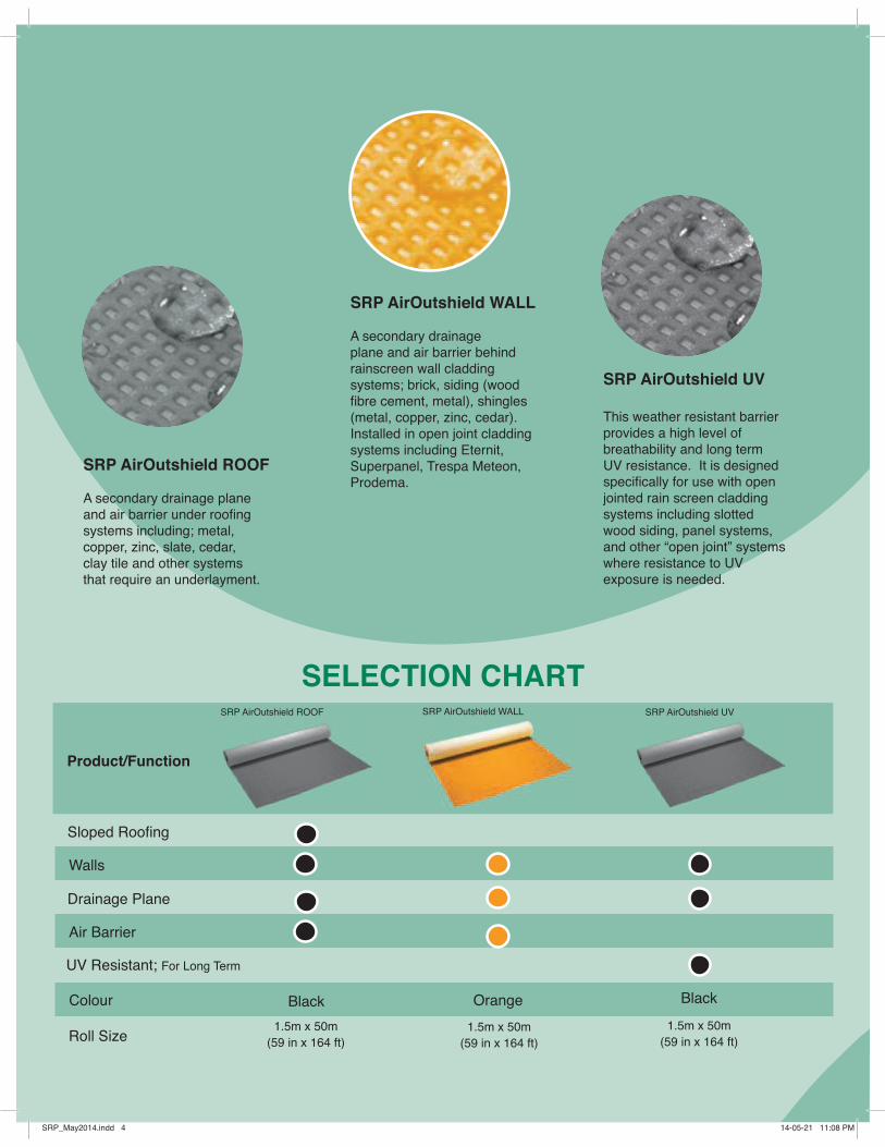
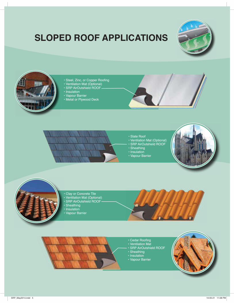
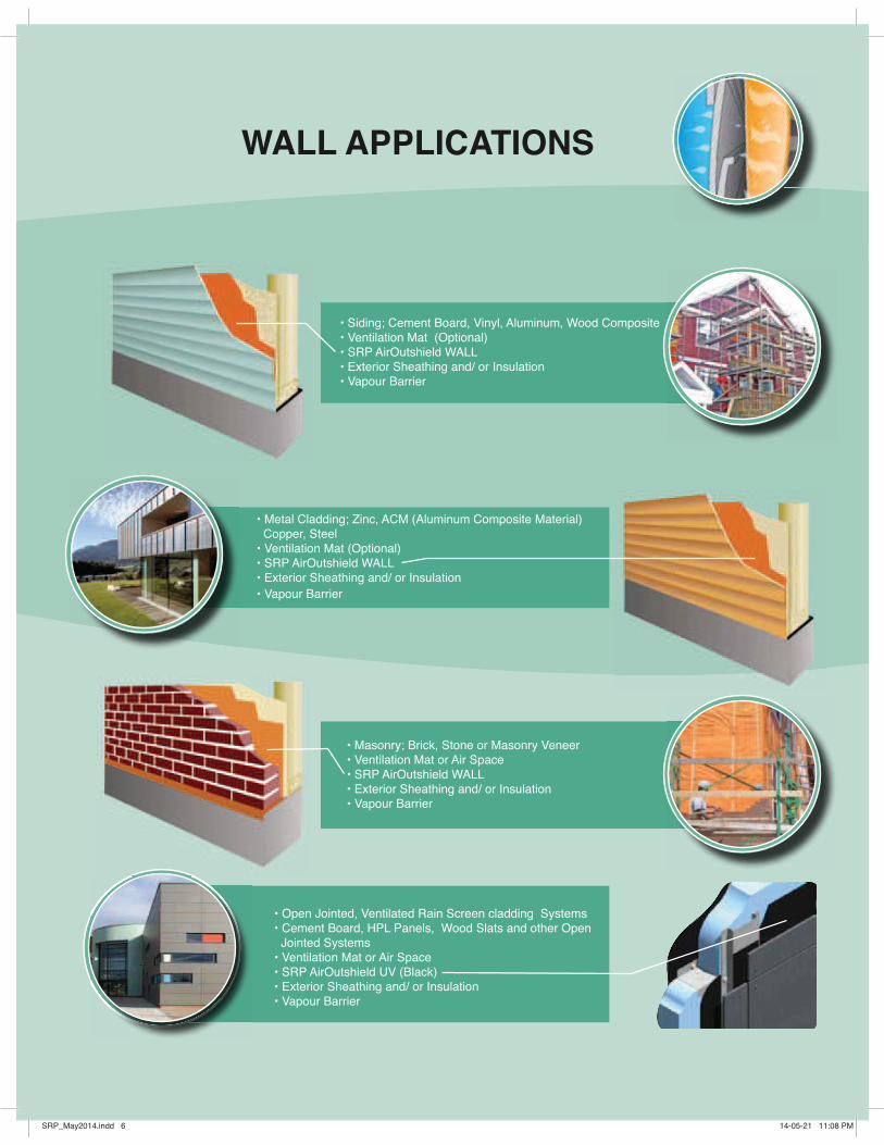
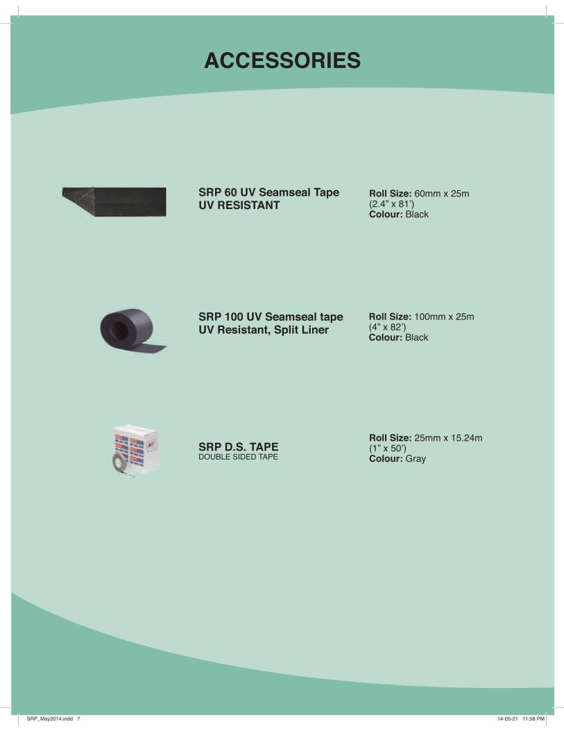
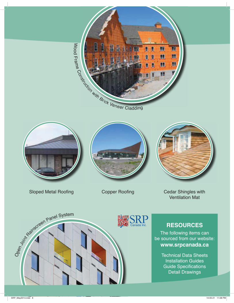
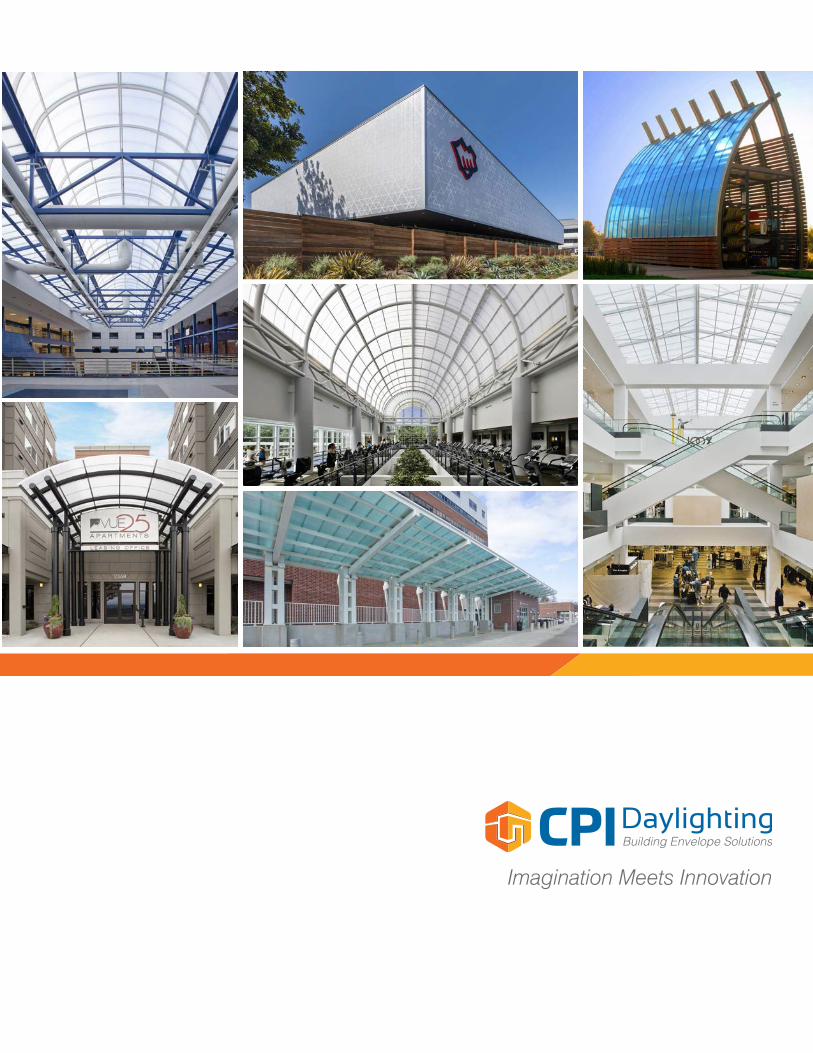
Imagination Meets Innovation
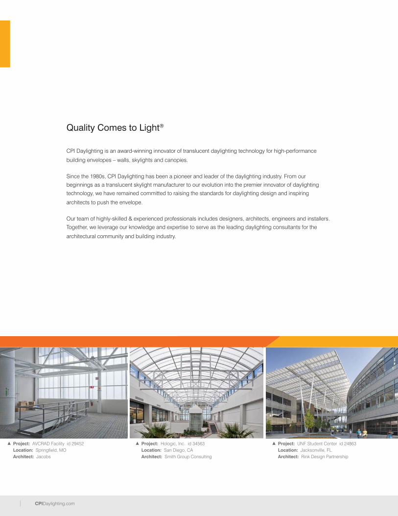
2 CPIDaylighting.comCPIDaylighting.com
Quality Comes to Light®
CPI Daylighting is an award-winning innovator of translucent daylighting technology for high-performance
building envelopes – walls, skylights and canopies.
Since the 1980s, CPI Daylighting has been a pioneer and leader of the daylighting industry. From our
beginnings as a translucent skylight manufacturer to our evolution into the premier innovator of daylighting
technology, we have remained committed to raising the standards for daylighting design and inspiring
architects to push the envelope.
Our team of highly-skilled & experienced professionals includes designers, architects, engineers and installers.
Together, we leverage our knowledge and expertise to serve as the leading daylighting consultants for the
architectural community and building industry.
Project: UNF Student Center id 24863Location: Jacksonville, FLArchitect: Rink Design Partnership
Project: Hologic, Inc. id 34563Location: San Diego, CA Architect: Smith Group Consulting
Project: AVCRAD Facility id 29452Location: Springfield, MOArchitect: Jacobs
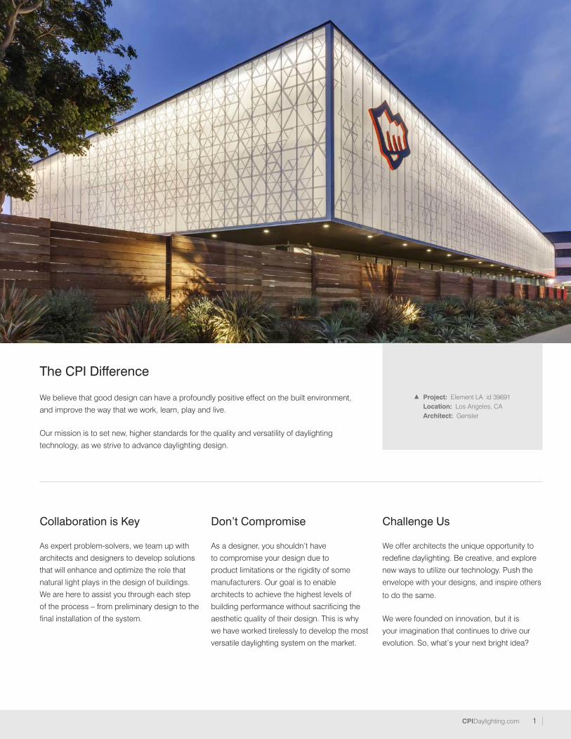
1CPIDaylighting.com
The CPI Difference
Collaboration is Key As expert problem-solvers, we team up with
architects and designers to develop solutions
that will enhance and optimize the role that
natural light plays in the design of buildings.
We are here to assist you through each step
of the process – from preliminary design to the
final installation of the system.
Don’t Compromise
As a designer, you shouldn’t have
to compromise your design due to
product limitations or the rigidity of some
manufacturers. Our goal is to enable
architects to achieve the highest levels of
building performance without sacrificing the
aesthetic quality of their design. This is why
we have worked tirelessly to develop the most
versatile daylighting system on the market.
Challenge Us
We offer architects the unique opportunity to
redefine daylighting. Be creative, and explore
new ways to utilize our technology. Push the
envelope with your designs, and inspire others
to do the same.
We were founded on innovation, but it is
your imagination that continues to drive our
evolution. So, what’s your next bright idea?
We believe that good design can have a profoundly positive effect on the built environment,
and improve the way that we work, learn, play and live.
Our mission is to set new, higher standards for the quality and versatility of daylighting
technology, as we strive to advance daylighting design.
Project: Element LA id 39691Location: Los Angeles, CAArchitect: Gensler
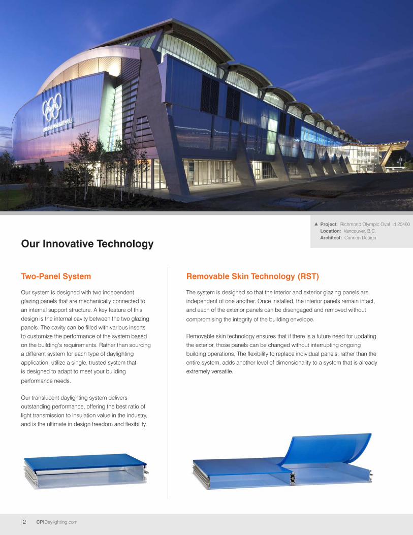
2 CPIDaylighting.com
Our Innovative Technology
Our system is designed with two independent
glazing panels that are mechanically connected to
an internal support structure. A key feature of this
design is the internal cavity between the two glazing
panels. The cavity can be filled with various inserts
to customize the performance of the system based
on the building’s requirements. Rather than sourcing
a different system for each type of daylighting
application, utilize a single, trusted system that
is designed to adapt to meet your building
performance needs.
Our translucent daylighting system delivers
outstanding performance, offering the best ratio of
light transmission to insulation value in the industry,
and is the ultimate in design freedom and flexibility.
The system is designed so that the interior and exterior glazing panels are
independent of one another. Once installed, the interior panels remain intact,
and each of the exterior panels can be disengaged and removed without
compromising the integrity of the building envelope.
Removable skin technology ensures that if there is a future need for updating
the exterior, those panels can be changed without interrupting ongoing
building operations. The flexibility to replace individual panels, rather than the
entire system, adds another level of dimensionality to a system that is already
extremely versatile.
Removable Skin Technology (RST)Two-Panel System
Project: Richmond Olympic Oval id 20460Location: Vancouver, B.C. Architect: Cannon Design

3CPIDaylighting.com
Bi-Color Panel Option
A different color can be selected for each of the two independent glazing panels that make up the system. As a designer, you may want to make
a bold statement by using colorful panels on the exterior and utilize a neutral panel color on the interior for a clean, finished look.
While glazing color combinations offer an opportunity for creativity, they also serve a practical purpose when tailoring the performance of the
system. Each glazing color has an inherent solar performance. By varying the combination of the glazing colors, not only can you create unique
visual elements, but you can also customize the solar performance of the system. The optional matte finish on the panels will increase their ability
to diffuse light and eliminate glare.
Longer Clear Spans
Due to the design of the internal support
structure, the panel system can achieve
longer spans and still comply with deflection
and code requirements. The ability to span
floor-to-slab minimizes the necessary support
structure – reducing the cost of material and
labor. It also improves the aesthetic quality of
the system.
Nano-Cell® Glazing
Our patented Pentaglas® translucent glazing
is precision engineered with Nano-Cell®
technology. This specialized panel extrusion
results in the cells measuring smaller
than 0.18 inches, and provides the panel
with increased durability and prolonged
resistance to impact. The unique cell
structure also significantly improves the
quality and even distribution of glare-free
natural light.

4 CPIDaylighting.com
One trusted systemInfinite possibilities
What’s your next bright idea?
Specialized Performance Options
We understand that due to budget, occupancy and building type, not all building
envelopes are made equal. That is why CPI Daylighting designed a system with an internal
cavity that can be modified with additional inserts to meet the performance requirements
of any building. Whether you need a system that can dynamically manage light levels in a
classroom, meet forced entry standards for a military facility, or anything in between, we
can help you achieve your performance goals.
• Dynamic Shading System
• Additional Insulation
• LED Lighting
Dynamic Shading System
Military Facility per DoD Standards
• Sound Reduction (STC)
• Forced Entry Resistance
• Perforated Metal Insert
Project: Akron Children's Hospital Parking Garage id 35531Location: Akron, OHArchitect: GPD Group
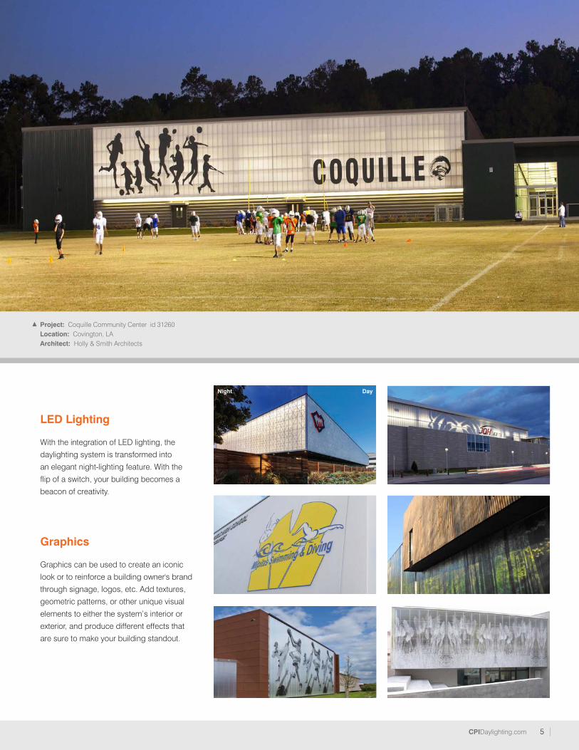
5CPIDaylighting.com
Graphics
Graphics can be used to create an iconic
look or to reinforce a building owner's brand
through signage, logos, etc. Add textures,
geometric patterns, or other unique visual
elements to either the system’s interior or
exterior, and produce different effects that
are sure to make your building standout.
LED Lighting
With the integration of LED lighting, the
daylighting system is transformed into
an elegant night-lighting feature. With the
flip of a switch, your building becomes a
beacon of creativity.
Project: Coquille Community Center id 31260Location: Covington, LAArchitect: Holly & Smith Architects
Night Day
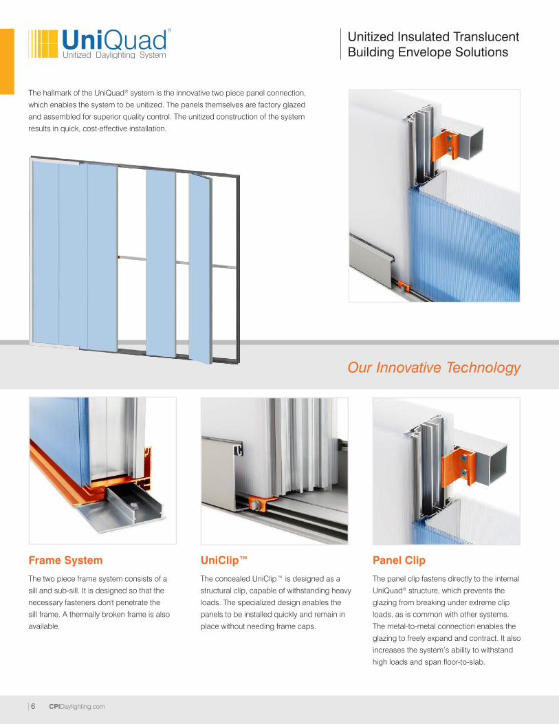
6 CPIDaylighting.com
Unitized Insulated Translucent Building Envelope Solutions
The hallmark of the UniQuad® system is the innovative two piece panel connection,
which enables the system to be unitized. The panels themselves are factory glazed
and assembled for superior quality control. The unitized construction of the system
results in quick, cost-effective installation.
Frame System
The two piece frame system consists of a
sill and sub-sill. It is designed so that the
necessary fasteners don't penetrate the
sill frame. A thermally broken frame is also
available.
UniClip™
The concealed UniClip™ is designed as a
structural clip, capable of withstanding heavy
loads. The specialized design enables the
panels to be installed quickly and remain in
place without needing frame caps.
Panel Clip
The panel clip fastens directly to the internal
UniQuad® structure, which prevents the
glazing from breaking under extreme clip
loads, as is common with other systems.
The metal-to-metal connection enables the
glazing to freely expand and contract. It also
increases the system’s ability to withstand
high loads and span floor-to-slab.
Our Innovative Technology
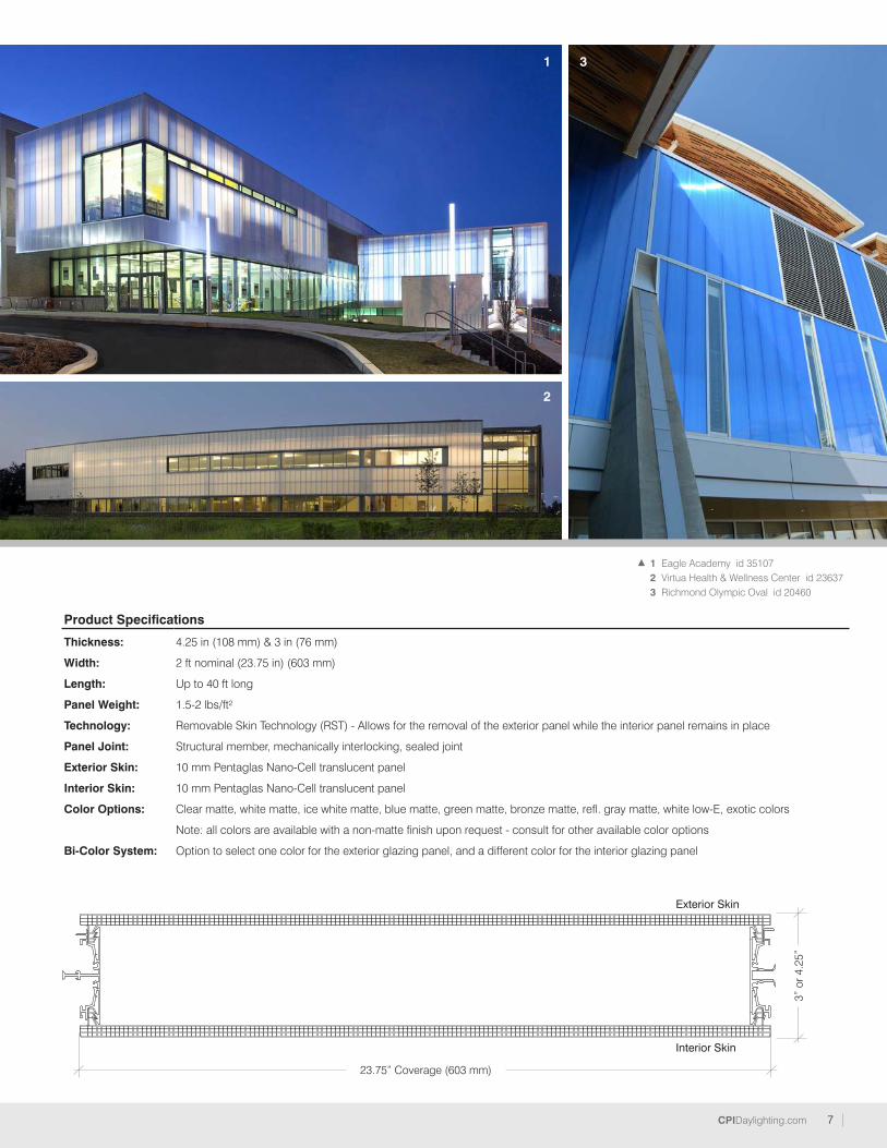
7CPIDaylighting.com
Product Specifications
Thickness: 4.25 in (108 mm) & 3 in (76 mm)
Width: 2 ft nominal (23.75 in) (603 mm)
Length: Up to 40 ft long
Panel Weight: 1.5-2 lbs/ft²
Technology: Removable Skin Technology (RST) - Allows for the removal of the exterior panel while the interior panel remains in place
Panel Joint: Structural member, mechanically interlocking, sealed joint
Exterior Skin: 10 mm Pentaglas Nano-Cell translucent panel
Interior Skin: 10 mm Pentaglas Nano-Cell translucent panel
Color Options: Clear matte, white matte, ice white matte, blue matte, green matte, bronze matte, refl. gray matte, white low-E, exotic colors
Note: all colors are available with a non-matte finish upon request - consult for other available color options
Bi-Color System: Option to select one color for the exterior glazing panel, and a different color for the interior glazing panel
Exterior Skin
Interior Skin
23.75” Coverage (603 mm)
3” o
r 4.2
5”
1 Eagle Academy id 351072 Virtua Health & Wellness Center id 236373 Richmond Olympic Oval id 20460
1
2
3
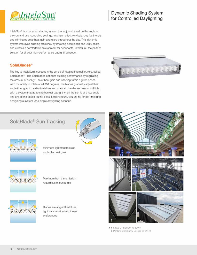
8 CPIDaylighting.com
1 Lucas Oil Stadium id 204682 Portland Community College id 34449
SolaBlades®
The key to IntelaSun's success is the series of rotating internal louvers, called
SolaBlades®. The SolaBlades optimize building performance by regulating
the amount of sunlight, solar heat gain and shading within a given space.
With the ability to rotate a full 360 degrees, the blades gradually adjust their
angle throughout the day to deliver and maintain the desired amount of light.
With a system that adapts to harvest daylight when the sun is at a low angle
and shade the space during peak sunlight hours, you are no longer limited to
designing a system for a single daylighting scenario.
Minimum light transmission
and solar heat gain
Maximum light transmission
regardless of sun angle
Blades are angled to diffuse
light transmission to suit user
preferences
IntelaSun® is a dynamic shading system that adjusts based on the angle of
the sun and user-controlled settings. Intelasun effectively balances light-levels
and eliminates solar heat gain and glare throughout the day. This dynamic
system improves building efficiency by lowering peak loads and utility costs,
and creates a comfortable environment for occupants. IntelaSun - the perfect
solution for all your high-performance daylighting needs.
Dynamic Shading System for Controlled Daylighting
SolaBlade® Sun Tracking
2
1
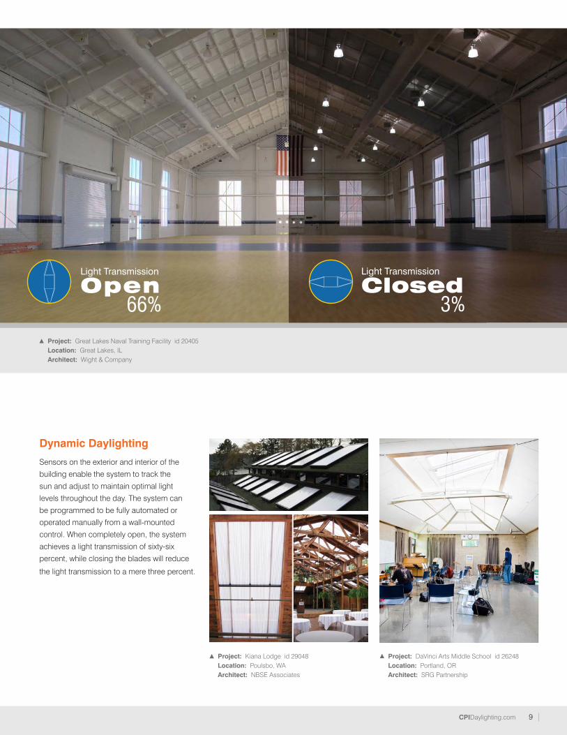
9CPIDaylighting.com
Project: Kiana Lodge id 29048Location: Poulsbo, WAArchitect: NBSE Associates
Project: DaVinci Arts Middle School id 26248Location: Portland, ORArchitect: SRG Partnership
Dynamic Daylighting
Sensors on the exterior and interior of the
building enable the system to track the
sun and adjust to maintain optimal light
levels throughout the day. The system can
be programmed to be fully automated or
operated manually from a wall-mounted
control. When completely open, the system
achieves a light transmission of sixty-six
percent, while closing the blades will reduce
the light transmission to a mere three percent.
Project: Great Lakes Naval Training Facility id 20405Location: Great Lakes, ILArchitect: Wight & Company
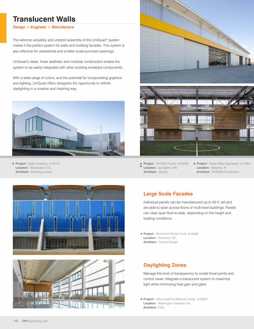
10 CPIDaylighting.com
The extreme versatility and unitized assembly of the UniQuad® system
makes it the perfect system for walls and building facades. This system is
also effective for clerestories and smaller scale punched openings.
UniQuad’s sleek, linear aesthetic and modular construction enable the
system to be easily integrated with other building envelope components.
With a wide range of colors, and the potential for incorporating graphics
and lighting, UniQuad offers designers the opportunity to rethink
daylighting in a creative and inspiring way.
Translucent WallsDesign + Engineer + Manufacture
Project: Cedar Valley Sportsplex id 34851Location: Waterloo, IAArchitect: INVISION Architecture
Project: Eagle Academy id 35107Location: Washington, D.C.Architect: Shinberg Levinas
Large Scale Facades
Individual panels can be manufactured up to 40 ft. tall and
are able to span across floors of multi-level buildings. Panels
can clear span floor-to-slab, depending on the height and
loading conditions.
Daylighting Zones
Manage the level of transparency to create focal points and
control views. Integrate a translucent system to maximize
light while minimizing heat gain and glare.
Project: Richmond Olympic Oval id 20460Location: Richmond, BCArchitect: Cannon Design
Project: Virtua Health & Wellness Center id 23637Location: Washington Township, NJArchitect: HGA
Project: AVCRAD Facility id 29452Location: Springfield, MOArchitect: Jacobs
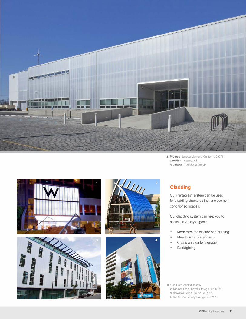
11CPIDaylighting.com
Project: Cedar Valley Sportsplex id 34851Location: Waterloo, IAArchitect: INVISION Architecture
Cladding
Our Pentaglas® system can be used
for cladding structures that enclose non-
conditioned spaces.
Our cladding system can help you to
achieve a variety of goals: • Modernize the exterior of a building
• Meet hurricane standards
• Create an area for signage
• Backlighting
Project: Juneau Memorial Center id 29775Location: Kearny, NJArchitect: The Musial Group
1 W Hotel Atlanta id 255912 Mission Creek Kayak Storage id 245323 Sarasota Police Station id 257724 3rd & Pine Parking Garage id 22125
1
3
2
4

12 CPIDaylighting.com
CPI Daylighting utilizes the latest in daylighting technology to provide the market
with efficient and effective solutions to meet their daylighting needs and enhance the
environments where we work, learn, play and live.
We offer a wide variety of skylight options - ranging in scale from small and simple to
monumental and complex. These skylights are available in a variety of standard shapes,
including vaults, ridges, single slopes, pyramids, polygons, and domes. We also work
with architects and designers to develop custom skylight systems.
Design + Engineer + Manufacture
Skylights over atriums and large common
spaces are an impactful design feature
that can make a space more inviting
and create an open and comfortable
environment for occupants.
Project: Stillaguamish Community Center id 38391Location: Arlington, WAArchitect: Womer and Associates
Project: Bogan Park Aquatic Center id 33261Location: Buford, GAArchitect: Wright & Mitchell Architects
Project: Bloomingdale's at Beverly Center id 35264Location: Los Angeles, CA
Project: Hologic, Inc. id 34563Location: San Diego, CA Architect: Smith Group Consulting
Skylights
Not only do we now have more light in our atrium, along with watertight
integrity, but we have strengthened our relationship with employees
and customers by providing an environment in which they can thrive.
“”– Pete Flood | Construction project manager, SAS

13CPIDaylighting.com
Project: Mall del Norte id 23445Location: Laredo, TXArchitect: Gary Gene Olp
Project: Office Park id 37542Location: San Jose, CA
Project: AVCRAD Facility id 29452Location: Springfield, MOArchitect: Jacobs
32
13
1
2
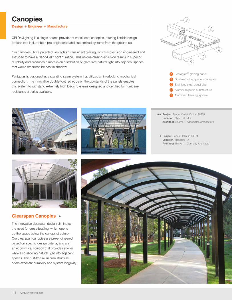
14 CPIDaylighting.com
Canopies
CPI Daylighting is a single source provider of translucent canopies, offering flexible design
options that include both pre-engineered and customized systems from the ground up.
Our canopies utilize patented Pentaglas® translucent glazing, which is precision engineered and
extruded to have a Nano-Cell® configuration. This unique glazing extrusion results in superior
durability and produces a more even distribution of glare-free natural light into adjacent spaces
that would otherwise be cast in shadow.
Pentaglas is designed as a standing seam system that utilizes an interlocking mechanical
connection. The innovative double-toothed edge on the up-stands of the panels enables
this system to withstand extremely high loads. Systems designed and certified for hurricane
resistance are also available.
A Pentaglas® glazing panel
B Double-toothed panel connector
C Stainless steel panel clip
D Aluminum purlin substructure
E Aluminum framing system
Project Jones Plaza id 28674Location Houston, TXArchitect Bricker + Cannady Architects
Project Tanger Outlet Mall id 36369Location Oxon Hill, MDArchitect Adams + Associates Architecture
Clearspan Canopies
The innovative clearspan design eliminates
the need for cross-bracing, which opens
up the space below the canopy structure.
Our clearspan canopies are pre-engineered
based on specific design criteria, and are
an economical solution that provides shelter
while also allowing natural light into adjacent
spaces. The rust-free aluminum structure
offers excellent durability and system longevity.
Design + Engineer + Manufacture
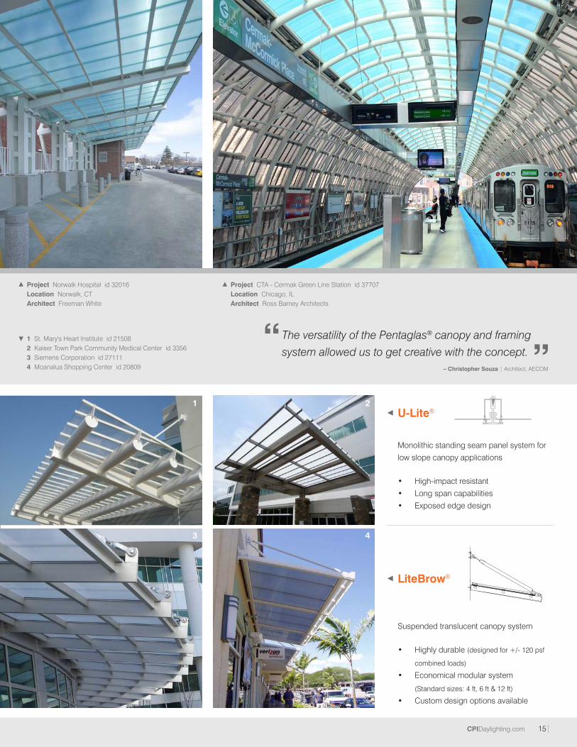
15CPIDaylighting.com
Project Norwalk Hospital id 32016Location Norwalk, CTArchitect Freeman White
Project CTA - Cermak Green Line Station id 37707Location Chicago, ILArchitect Ross Barney Architects
1 St. Mary's Heart Institute id 215082 Kaiser Town Park Community Medical Center id 33563 Siemens Corporation id 271114 Moanalua Shopping Center id 20809
LiteBrow®
Suspended translucent canopy system
• Highly durable (designed for +/- 120 psf
combined loads)
• Economical modular system
(Standard sizes: 4 ft, 6 ft & 12 ft)
• Custom design options available
U-Lite®
Monolithic standing seam panel system for
low slope canopy applications
• High-impact resistant
• Long span capabilities
• Exposed edge design
1
3
2
4
The versatility of the Pentaglas® canopy and framing
system allowed us to get creative with the concept.“ ”– Christopher Souza | Architect, AECOM
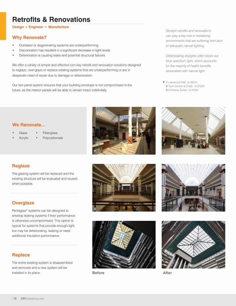
16 CPIDaylighting.com
1 Lakewood Mall id 392242 Town Center at Cobb id 272243 Embassy Suites id 34534
Overglaze
Pentaglas® systems can be designed to
envelop leaking systems if their performance
is otherwise uncompromised. This option is
typical for systems that provide enough light,
but may be deteriorating, leaking or need
additional insulation performance.
Reglaze
The glazing system will be replaced and the
existing structure will be evaluated and reused
when possible.
Replace
The entire existing system is disassembled
and removed and a new system will be
installed in its place.
Skylight retrofits and renovations
can play a key role in revitalizing
environments that are suffering from lack
of adequate natural lighting.
Deteriorating skylights often block out
blue spectrum light, which accounts
for the majority of health benefits
associated with natural light.
We Renovate...
• Glass
• Acrylic
• Fiberglass
• Polycarbonate
Why Renovate?
• Outdated or degenerating systems are underperforming
• Discoloration has resulted in a significant decrease in light levels
• Deterioration is causing leaks and potential structural failures
We offer a variety of simple and effective turn-key retrofit and renovation solutions designed
to reglaze, over-glaze or replace existing systems that are underperforming or are in
desperate need of repair due to damage or deterioration.
Our two panel system ensures that your building envelope is not compromised in the
future, as the interior panels will be able to remain intact indefinitely.
Retrofits & RenovationsDesign + Engineer + Manufacture
1
2
3
Before After
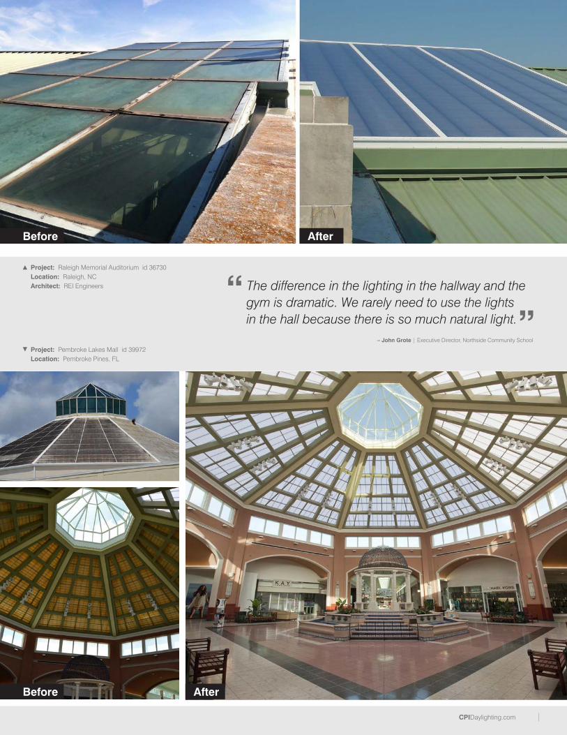
CPIDaylighting.com
Project: Raleigh Memorial Auditorium id 36730Location: Raleigh, NCArchitect: REI Engineers
Project: Pembroke Lakes Mall id 39972Location: Pembroke Pines, FL
Before
Before
After
After
The difference in the lighting in the hallway and the gym is dramatic. We rarely need to use the lights in the hall because there is so much natural light.
“”
– John Grote | Executive Director, Northside Community School
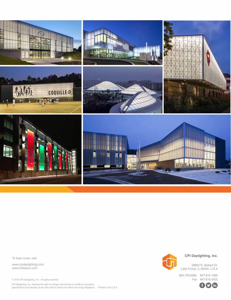
800.759.6985 847.816.1060
www.cpidaylighting.comwww.intelasun.com
Fax 847.816.0425
28662 N. Ballard Dr.Lake Forest, IL 60045 U.S.A
To learn more, visit:
CPI Daylighting, Inc. reserves the right to change, discontinue or modify our products, specifications and designs at any time without notice and without incurring obligations. - Printed in the U.S.A.
© 2015 CPI Daylighting, Inc. All rights reserved.
CPI Daylighting, Inc.