COOLING AND LUBRICATION SYSTEM - · PDF filecooling and lubrication system. 5-2 cooling and...
23
COOLINGANDLUBRICATIONSYSTEM COOLINGANDLUBRICATION SYSTEM5-1 CONTENTS ENGINECOOLANT 5-3 COOLINGCIRCUIT 5-4 INSPECTION 5-4 RADIATOR 5-5 REMOVAL 5-5 INSTALLATION 5-6 INSPECTIONANDCLEANING 5-6 RADIATORRESERVOIRTANK 5-7 REMOVALANDINSTALLATION 5-7 RADIATORCAP 5-7 INSPECTION 5-7 WATERHOSE 5-7 INSPECTION 5-7 COOLINGFAN 5-8 REMOVALANDINSTALLATION 5-8 INSPECTION 5-8 COOLINGFANTHERMO-SWITCH 5-9 REMOVAL 5-9 INSPECTION 5-9 INSTALLATION 5-9 ENGINECOOLANTTEMPERATURESENSOR 5-10 REMOVAL 5-10 INSPECTION 5-10 INSTALATION 5-11 THERMOSTAT 5-12 REMOVAL 5-12 INSPECTION 5-12 INSTALLATION 5-13 WATERPUMP 5-14 REMOVALANDDISASSEMBLY 5-14 INSPECTIONANDCLEANING 5-15 REASSEMBLYANDINSTALLATION 5-16 LUBRICATIONSYSTEM 5-19 OILPRESSURE 5-19 OILFILTER 5-19 OILPRESSUREREGULATOR 5-19 OILSTRAINER 5-19 OILJET 5-19 OILPUMP 5-19 5 ,of
Transcript of COOLING AND LUBRICATION SYSTEM - · PDF filecooling and lubrication system. 5-2 cooling and...

COOLING AND LUBRICATION SYSTEMCOOLING AND LUBRICATION SYSTEM 5-1
CONTENTSENGINE COOLANT 5- 3COOLING CIRCUIT 5- 4
INSPECTION 5- 4RADIATOR 5- 5
REMOVAL 5- 5INSTALLATION 5- 6INSPECTION AND CLEANING 5- 6
RADIATOR RESERVOIR TANK 5- 7REMOVAL AND INSTALLATION 5- 7
RADIATOR CAP 5- 7INSPECTION 5- 7
WA TER HOSE 5- 7INSPECTION 5- 7
COOLING FAN 5- 8REMOVAL AND INSTALLATION 5- 8INSPECTION 5- 8
COOLING FAN THERMO-SWITCH 5- 9REMOVAL 5- 9INSPECTION 5- 9INSTALLATION 5- 9
ENGINE COOLANT TEMPERATURE SENSOR5-10REMOVAL 5-10INSPECTION 5-10INS TA LA TION 5-11
THERMOSTAT 5-12REMOVAL 5-12INSPECTION 5-12INSTALLATION 5-13
WATER PUMP 5-14REMOVAL AND DISASSEMBLY 5-14INSPECTION AND CLEANING 5-15REASSEMBLY AND INSTALLATION 5-16
LUBRICATION SYSTEM 5-19OIL PRESSURE 5-19OIL FILTER 5-19OIL PRESSURE REGULATOR 5-19OIL STRAINER 5-19OIL JET 5-19OIL PUMP 5-19
5
,of

COOLING AND LUBRICATION SYSTEM .
5-2 COOLING AND LUBRICATION SYSTEM
CONTENTS
OIL PRESSURE SWITCH 5-19OIL COOLER 5-20
REMOVAL 5-20INSTALLATION 5-21INSPECTION AND CLEANING 5-21
ENGINE LUBRICATION FLOW CHART 5-22ENGINE LUBRICATION CIRCUIT 5-23
04
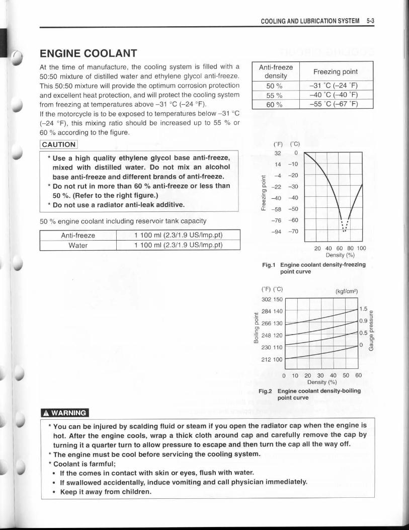
ENGINE COOLANTAt the time of manufacture, the cooling system is filled with a
50 :50 mixture of distilled water and ethylene glycol anti-freeze .
This 50:50 mixture will provide the optimum corrosion protection
and excellent heat protection, and will protect the cooling system
from freezing at temperatures above -31 °C (-24 °F) .
If the motorcycle is to be exposed to temperatures below -31 °C
(-24 °F), this mixing ratio should be increased up to 55 % or
60 % according to the figure .
CAUTION
• Use a high quality ethylene glycol base anti-freeze,
mixed with distilled water . Do not mix an alcohol
base anti-freeze and different brands of anti-freeze .
• Do not rut in more than 60 % anti-freeze or less than
50 %. (Refer to the right figure .)
•
Do not use a radiator anti-leak additive .
A WARNING
COOLING AND LUBRICATION SYSTEM 5-3
20 40 60 80 100
0 10 20 30 40 50 60Density (%)
Fig.2 Engine coolant density-boilingpoint curve
•
You can be injured by scalding fluid or steam if you open the radiator cap when the engine is
hot. After the engine cools, wrap a thick cloth around cap and carefully remove the cap by
turning it a quarter turn to allow pressure to escape and then turn the cap all the way off .
•
The engine must be cool before servicing the cooling system .
•
Coolant is farmful ;
•
If the comes in contact with skin or eyes, flush with water .
•
If swallowed accidentally, induce vomiting and call physician immediately .
•
Keep it away from children .
Anti-freezedensity
Freezing point
50% -31 °C (-24 °F)
55% -40 °C (-40 °F)
60% -55 °C (-67 °F)
50 % engine coolant including reservoir tank capacity
Anti-freeze 1 100 ml (2 .3/1 .9 US/Imp-pt)
Water 1 100 ml (2 .3/1 .9 US/Imp.pt)
Density (%)
Fig.1 Engine coolant density-freezingpoint curve
(°F) (°C)302 150
(kgf/cm2)
284 140 1 .5cQ 266 130 0.90) a)
:0 248 120 0.50)m Z3
230 1100
(7
212 100
(F) (C)32 0
14 -10
-4 -20C0Q -22 -30O)CN -40 -40a)a)U- -58 -50
-76 -60
-94 -70

5- 4 COOLING AND LUBRICATION SYSTEM
COOLING CIRCUIT
THERMOSTAT
RESERVOIR TANK
RADIATOR
NO. 1 CYLINDER HEAD
NO. 1 CYLINDER
NO. 2 CYLINDER
NO. 2 CYLINDER HEAD
WATER PUMP
INSPECTIONBefore removing the radiator and draining engine coolant,
inspect the cooling circuit for tightness .
•
Remove the body cowling. (=6-6)
•
Remove the radiator cap ® .
•
Connect the tester 02 to the filler .
A WARNING
Do not remove the radiator cap when the engine is
hot.
•
Give a pressure of about 110 kPa (1 .1 kgf/cm 2 , 15 .6 psi) and
see if the system holds this pressure for 10 seconds .
•
If the pressure should fall during this 10-second interval, it
means that there is a leaking point in the system . In such a
case, inspect the entire system and replace the leaking com-
ponent or part .
A WARNING
When removing the radiator cap tester, put a rag on
the filler to prevent spouting of engine coolant .
CAUTION
Do not allow the pressure to exceed the radiator cap
release pressure, or the radiator can be damaged .
I
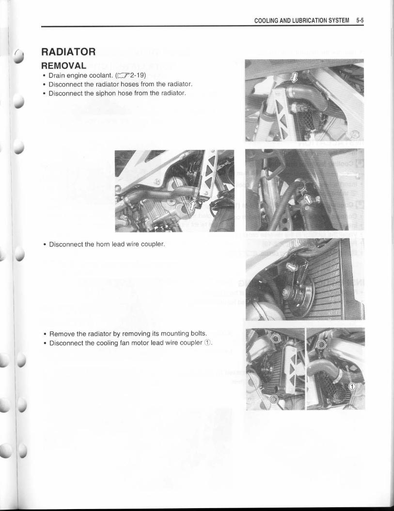
RADIATOR40 REMOVAL
•
Drain engine coolant . (C-.7-2-19)
•
Disconnect the radiator hoses from the radiator .
•
Disconnect the siphon hose from the radiator .
•
Disconnect the horn lead wire coupler .
•
Remove the radiator by removing its mounting bolts .
•
Disconnect the cooling fan motor lead wire coupler 10 .
COOLING AND LUBRICATION SYSTEM 5-5
5-6 COOLING AND LUBRICATION SYSTEM
•
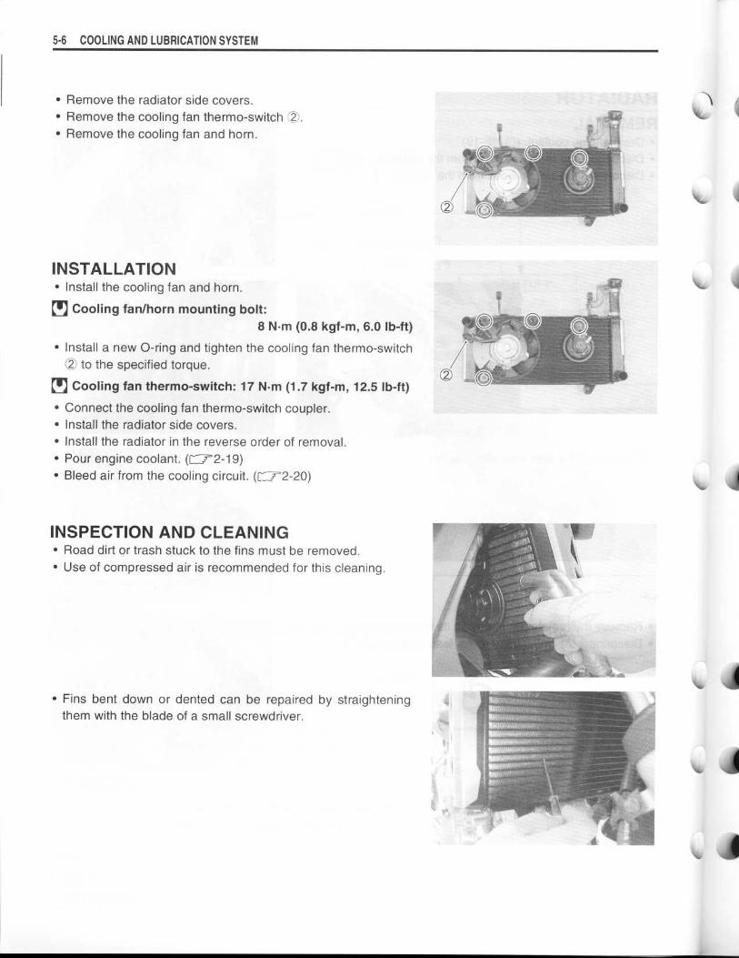
Remove the radiator side covers .•
Remove the cooling fan thermo-switch 02 .
•
Remove the cooling fan and horn .
INSTALLATION
•
Install the cooling fan and horn .
•
Cooling fan/horn mounting bolt :
8 N .m (0.8 kgf-m, 6.0 lb-ft)
•
Install a new 0-ring and tighten the cooling fan thermo-switch
02 to the specified torque .
•
Cooling fan thermo-switch : 17 N.m (1 .7 kgf-m, 12.5 lb-ft)
•
Connect the cooling fan thermo-switch coupler .
•
Install the radiator side covers .
•
Install the radiator in the reverse order of removal .
•
Pour engine coolant . (F-72-19)•
Bleed air from the cooling circuit . (CI2-20)
INSPECTION AND CLEANING
•
Road dirt or trash stuck to the fins must be removed .
•
Use of compressed air is recommended for this cleaning .
•
Fins bent down or dented can be repaired by straightening
them with the blade of a small screwdriver .

RADIATOR RESERVOIR TANKREMOVAL AND INSTALLATION•
Lift and support the fuel tank . (r r4-65)•
Disconnect the siphon hose from the radiator .•
Remove the reservoir tank by removing its mounting bolt .•
Drain engine coolant .•
Install the reservoir tank in the reverse order of removal .•
Fill the reservoir tank to the upper level .
RADIATOR CAPINSPECTION•
Fit the cap 90 to the radiator cap tester (2) .
•
Build up pressure slowly by operating the tester . Make surethat the pressure build-up stops at 95 - 125 kPa (0.95 - 1 .25kgf/cm 2 , 13.5 - 17.8 psi) and that, with the tester held stand-
still, the cap is capable of holding that pressure for at least 10
seconds .
•
Replace the cap if it is found not to satisfy either of these two
requirements .
Radiator cap valve opening pressure
Standard :
95 - 125 kPa (0 .95 - 1 .25 kgf/cm2 , 13.5 - 17.8 psi)
WATER HOSEINSPECTION•
Any water hose found in a cracked condition or flattened or
water leaked must be replaced .
•
Any leakage from the connecting section should be corrected
by proper tightening .
COOLING AND LUBRICATION SYSTEM 5-7

5 -8 COOLING AND LUBRICATION SYSTEM
COOLING FANREMOVAL AND INSTALLATIONREMOVAL•
Remove the steering stem lower plate 10 .
•
Remove the radiator mounting bolts .
•
Move the radiator forward .
•
Disconnect the cooling fan motor lead wire coupler O and
cooling fan thermo-switch coupler ® .•
Remove the cooling fan .
INSTALLATION
•
Install the cooling fan and radiator in the reverse order of
removal .
Cooling fan motor mounting bolt :8 N.m (0.8 kgf-m, 6 .0 Ib-ft)
INSPECTION•
Disconnect the cooling fan motor lead wire coupler O .•
Test the cooling fan motor for load current with an ammeter
connected as shown in the illustration .
• The voltmeter is for making sure that the battery applies 12 V
to the motor. With the motor with electric motor fan running at
full speed, the ammeter should be indicating not more than 5
amperes .
•
If the fan motor does not turn, replace the motor assembly
with a new one .
NOTE:
When making above test, it is not necessary to remove the cool-
ing fan .
WAN
114
/
~ 40
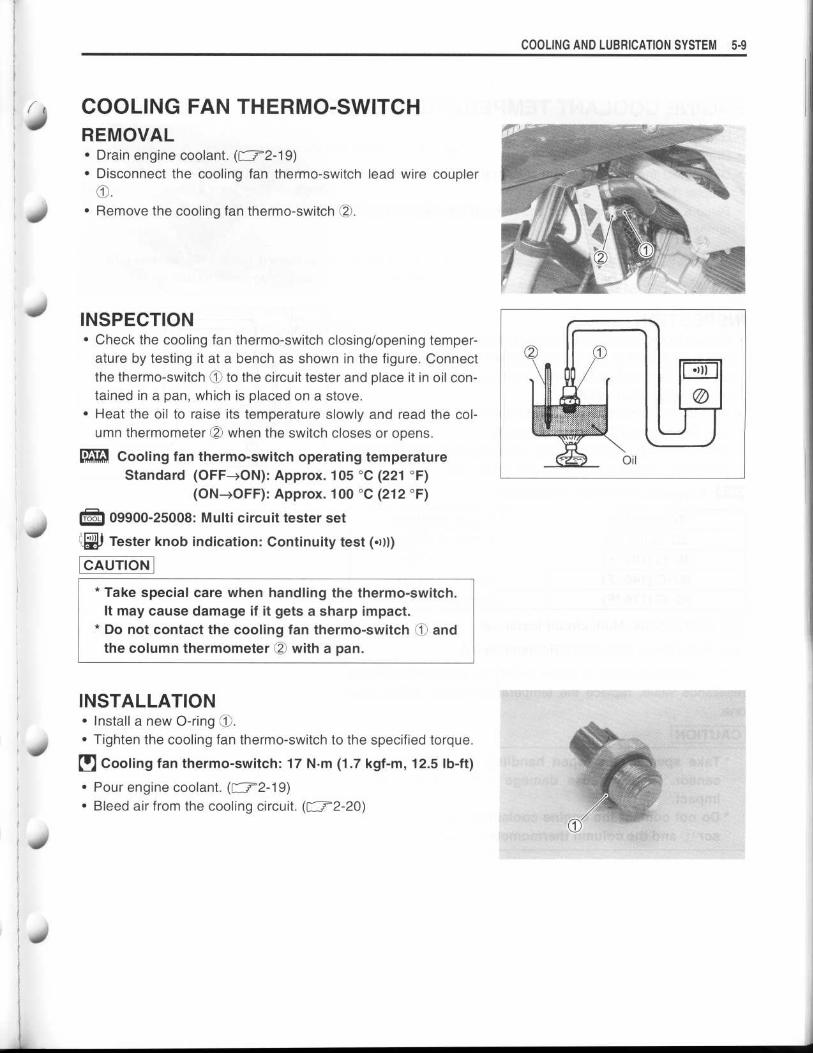
COOLING FAN THERMO-SWITCHREMOVAL•
Drain engine coolant . ([72-19)•
Disconnect the cooling fan thermo-switch lead wire coupler10 .
•
Remove the cooling fan thermo-switch (2 .
INSPECTION•
Check the cooling fan thermo-switch closing/opening temper-ature by testing it at a bench as shown in the figure . Connectthe thermo-switch 1) to the circuit tester and place it in oil con-tained in a pan, which is placed on a stove .
•
Heat the oil to raise its temperature slowly and read the col-umn thermometer (2 when the switch closes or opens .
Cooling fan thermo-switch operating temperatureStandard (OFF-ON) : Approx. 105 °C (221 °F)
(ON-DOFF): Approx. 100 °C (212 °F)
09900-25008 : Multi circuit tester set
Tester knob indication : Continuity test ( •) l))
CAUTION
•
Take special care when handling the thermo-switch .It may cause damage if it gets a sharp impact .
•
Do not contact the cooling fan thermo-switch (1) andthe column thermometer 02 with a pan .
INSTALLATION•
Install a new 0-ring 1O .•
Tighten the cooling fan thermo-switch to the specified torque .
0 Cooling fan thermo-switch : 17 N.m (1 .7 kgf-m, 12.5 lb-ft)
•
Pour engine coolant . (F-7-2-19)•
Bleed air from the cooling circuit . (r-7-2-20)
COOLING AND LUBRICATION SYSTEM 5 -9
020
5- 1 0 COOLING AND LUBRICATION SYSTEM
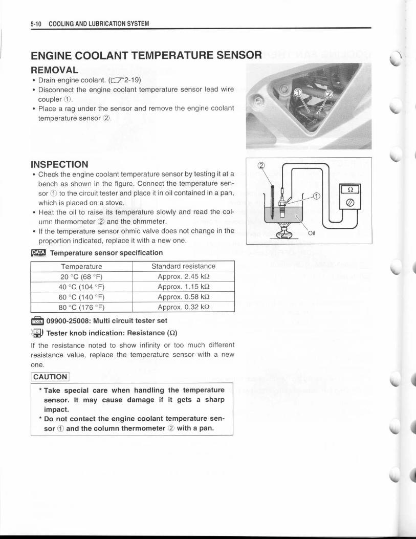
ENGINE COOLANT TEMPERATURE SENSORREMOVAL•
Drain engine coolant . (f- 2-19)•
Disconnect the engine coolant temperature sensor lead wirecoupler 10 .
•
Place a rag under the sensor and remove the engine coolanttemperature sensor OO .
INSPECTION• Check the engine coolant temperature sensor by testing it at abench as shown in the figure . Connect the temperature sen-sor O to the circuit tester and place it in oil contained in a pan,which is placed on a stove .
•
Heat the oil to raise its temperature slowly and read the col-umn thermometer OO and the ohmmeter .
•
If the temperature sensor ohmic valve does not change in theproportion indicated, replace it with a new one .
Temperature sensor specification
09900-25008 : Multi circuit tester set
o Tester knob indication : Resistance (0)
If the resistance noted to show infinity or too much differentresistance value, replace the temperature sensor with a newone .
CAUTION
* Take special care when handling the temperaturesensor. It may cause damage if it gets a sharpimpact .
* Do not contact the engine coolant temperature sen-sor ® and the column thermometer OO with a pan .
Temperature Standard resistance20 °C (68 °F) Approx . 2 .45 kQ40 °C (104 °F) Approx . 1 .15 k460 °C (140 °F) Approx . 0 .58 kQ80 °C (176 °F) Approx . 0 .32 kQ

INSTALATION•
Install a new sealing washer (j) .•
Tighten the engine coolant temperature sensor to the speci-
fied torque .
0 Engine coolant temperature sensor :
18 N.m (1 .8 kgf-m, 10.6 Ib-ft)
CAUTION
Take special care when handling the temperature sen-
sor. It may cause damage if it gets a sharp impact.
•
Pour engine coolant . (f- 2-19)
•
Bleed air from the cooling circuit . (C 1-2-20)
COOLING AND LUBRICATION SYSTEM 5-1 1
5 -12 COOLING AND LUBRICATION SYSTEM
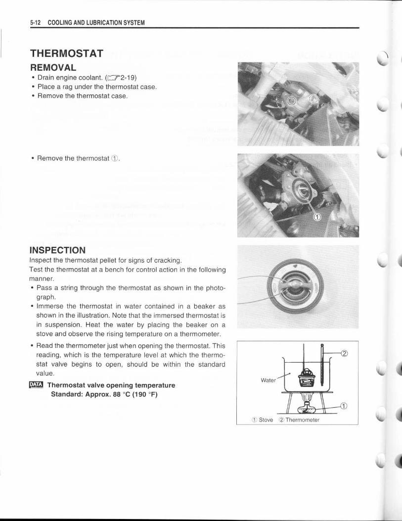
THERMOSTATREMOVAL•
Drain engine coolant . (r--r2-19)•
Place a rag under the thermostat case .
•
Remove the thermostat case .
•
Remove the thermostat O.
INSPECTIONInspect the thermostat pellet for signs of cracking .
Test the thermostat at a bench for control action in the followingmanner .
•
Pass a string through the thermostat as shown in the photo-
graph .
• Immerse the thermostat in water contained in a beaker as
shown in the illustration . Note that the immersed thermostat is
in suspension. Heat the water by placing the beaker on astove and observe the rising temperature on a thermometer .
• Read the thermometer just when opening the thermostat . This
reading, which is the temperature level at which the thermo-
stat valve begins to open, should be within the standardvalue .
Thermostat valve opening temperature
Standard : Approx. 88 °C (190 °F)
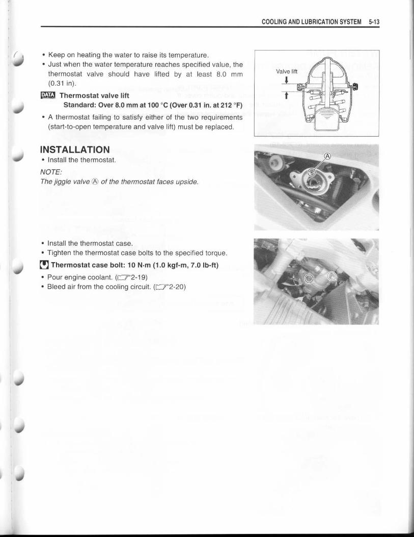
• Keep on heating the water to raise its temperature .
•
Just when the water temperature reaches specified value, the
thermostat valve should have lifted by at least 8 .0 mm(0.31 in) .
Thermostat valve lift
Standard: Over 8.0 mm at 100 °C (Over 0.31 in. at 212 °F)
•
A thermostat failing to satisfy either of the two requirements
(start-to-open temperature and valve lift) must be replaced .
INSTALLATION•
Install the thermostat .
NOTE:
The jiggle valve OO of the thermostat faces upside .
•
Install the thermostat case .
•
Tighten the thermostat case bolts to the specified torque .
0 Thermostat case bolt : 10 N .m (1 .0 kgf-m, 7 .0 Ib-ft)
•
Pour engine coolant . (f r 2-19)•
Bleed air from the cooling circuit . (F-72-20)
COOLING AND LUBRICATION SYSTEM 5- 1 3

5- 1 4 COOLING AND LUBRICATION SYSTEM
WATER PUMPREMOVAL AND DISASSEMBLYNOTE:Before draining engine oil and engine coolant, inspect engine oil
and coolant leakage between the water pump and clutch cover. If
engine oil is leaking, visually inspect the oil seal and O-ring . If
engine coolant is leaking, visually inspect the mechanical seal and
seal ring. (=5-15)
•
Remove the under cowling. (=6-5)
•
Drain engine coolant . (r72-19)
•
Drain engine oil . (=2-14)
•
Disconnect the water hoses .
•
Remove the water pump case .
•
Remove the clutch cover .
•
Remove the E-ring from the impeller shaft .
•
Remove the impeller .
•
Remove the mechanical seal ring C1 and the rubber seal !2D
from the impeller . 14

S
•
Remove the bearings with the special tool and proper bars .
09921-20240: Bearing remover set. .
NOTE:If there is no abnormal noise, bearing removal is not necessary.
CAUTION
The removed bearing must be replaced with a new
one.
•
Remove the mechanical seal using the special tool .
09921-20240: Bearing remover set
NOTE:
If there is no abnormal condition, the mechanical seal removal is
not necessary.
CAUTION
The removed mechanical seal must be replaced with a
new one .
•
Remove the oil seal using a suitable bar .
NOTE:
If there is no abnormal condition, the oil seal removal is not nec-
essary.
CAUTION
The removed oil seal must be replaced with a new one .
INSPECTION AND CLEANINGBEARING•
Inspect the play of the bearings by hand while they are in the
clutch cover .
•
Rotate the inner race by hand to inspect for abnormal noise
and smooth rotation .
•
Replace the bearing if there is anything unusual .
MECHANICAL SEAL•
Visually inspect the mechanical seal for damage, with particu-
lar attention given to the sealing face .
•
Replace the mechanical seal that shows indications of leak-
age . Also replace the seal ring if necessary .
COOLING AND LUBRICATION SYSTEM 5- 1 5
Em
fim

5- 1 6 COOLING AND LUBRICATION SYSTEM
OIL SEAL•
Visually inspect the oil seal for damage, with particular atten-tion given to the lip .
•
Replace the oil seal that shows indications of leakage .
REASSEMBLY AND INSTALLATION•
Install the oil seal using the special tool .
09913-70210 : Bearing installer set
NOTE:The stamped mark on the oil seal faces outside .
•
Apply a small quantity of the SUZUKI SUPER GREASE to theoil seal lip .
99000-25030 : SUZUKI SUPER GREASE "A" (USA)99000-25010 : SUZUKI SUPER GREASE "A" (Others)
•
Install the new mechanical seal using a suitable size socketwrench .
NOTE:On the new mechanical seal, the sealer A) has been applied .
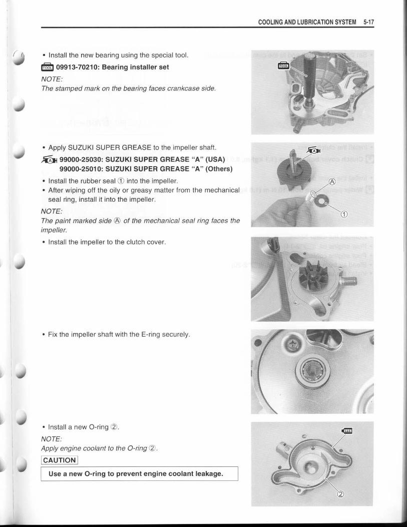
• Install the new bearing using the special tool .
09913-70210: Bearing installer set
NOTE:
The stamped mark on the bearing faces crankcase side .
•
Apply SUZUKI SUPER GREASE to the impeller shaft .
99000-25030: SUZUKI SUPER GREASE "A" (USA)99000-25010: SUZUKI SUPER GREASE "A" (Others)
•
Install the rubber seal 1O into the impeller .
•
After wiping off the oily or greasy matter from the mechanical
seal ring, install it into the impeller .
NOTE:
The paint marked side OO of the mechanical seal ring faces the
impeller.
•
Install the impeller to the clutch cover .
•
Fix the impeller shaft with the E-ring securely .
•
Install a new 0-ring OO .
NOTE:
Apply engine coolant to the O-ring OO .
CAUTION
Use a new O-ring to prevent engine coolant leakage .
COOLING AND LUBRICATION SYSTEM 5-17
EM

5-18 COOLING AND LUBRICATION SYSTEM
•
Set the impeller shaft end to the cam drive idle shaft .
( r-T3-91)
•
Install the clutch cover .
© Clutch cover bolt : 11 N.m (1 .1 kgf-m, 8 .0 lb-ft)
•
Install the water pump case .
0 Water pump case bolt : 10 N.m (1 .0 kgf-m, 7 .3 lb-ft)
•
Connect the water hoses .
•
Pour engine oil . (1I72-14)
•
Pour engine coolant . (r--72-19)
•
Bleed air from the cooling circuit . (=2-20)
•
Install the under cowling .

d/
nI
LUBRICATION SYSTEMOIL PRESSUREF-72-32
OIL FILTERF--72-15
OIL PRESSURE REGULATORC-73-67
OIL STRAINER=3-28 and -85
OIL JETr-7'3-68, -69 and -95
OIL PUMP=3-66 and -67
OIL PRESSURE SWITCHC'3-67, 7-29 and -30
COOLING AND LUBRICATION SYSTEM 5- 1 9
5-2 0 COOLING AND LUBRICATION SYSTEM
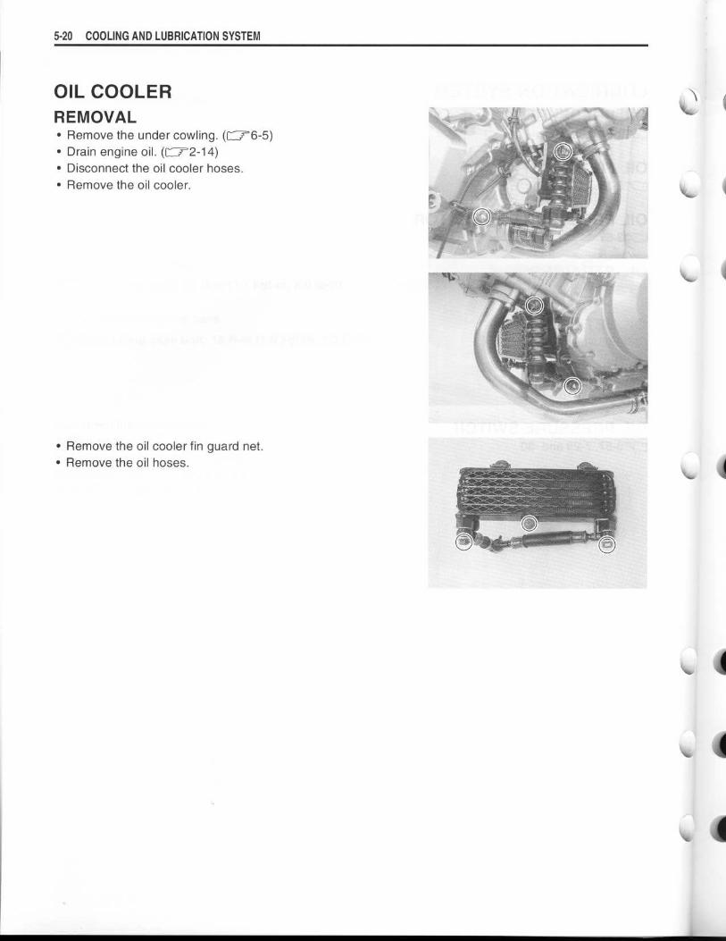
OIL COOLERREMOVAL•
Remove the under cowling . (f'"'6-5)
•
Drain engine oil . (=2-14)•
Disconnect the oil cooler hoses .•
Remove the oil cooler .
•
Remove the oil cooler fin guard net .
•
Remove the oil hoses .
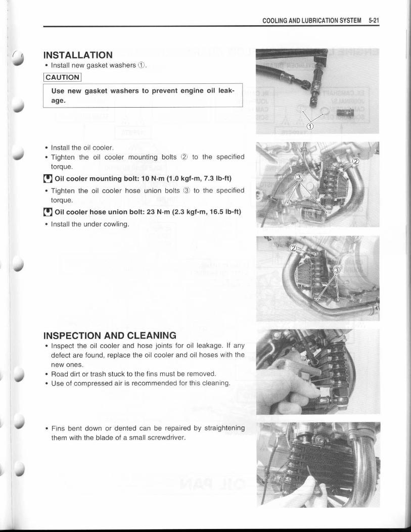
I INSTALLATION•
Install new gasket washers 90 .
CAUTION
Use new gasket washers to prevent engine oil leak-
age .
•
Install the oil cooler .
•
Tighten the oil cooler mounting bolts (2) to the specified
torque .
•
Oil cooler mounting bolt : 10 N .m (1 .0 kgf-m, 7.3 Ib-ft)
•
Tighten the oil cooler hose union bolts 03 to the specified
torque .
•
Oil cooler hose union bolt: 23 N.m (2 .3 kgf-m, 16.5 lb-ft)
•
Install the under cowling .
INSPECTION AND CLEANING• Inspect the oil cooler and hose joints for oil leakage . If any
defect are found, replace the oil cooler and oil hoses with the
new ones .
•
Road dirt or trash stuck to the fins must be removed .
•
Use of compressed air is recommended for this cleaning .
•
Fins bent down or dented can be repaired by straightening
them with the blade of a small screwdriver .
COOLING AND LUBRICATION SYSTEM 5-2 1
5- 22 COOLING AND LUBRICATION SYSTEM
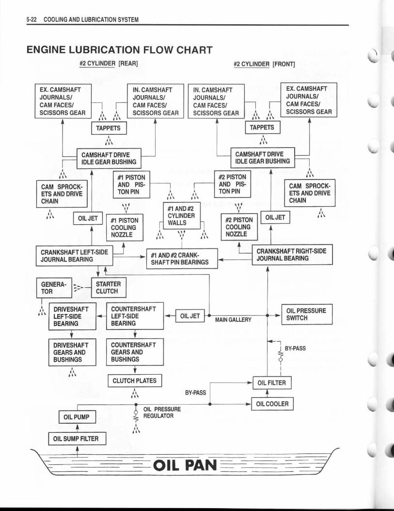
ENGINE LUBRICATION FLOW CHART
#2 CYLINDER [REAR]
#2 CYLINDER [FRONT]
EX. CAMSHAFTJOURNALS/CAM FACES/SCISSORS GEAR
iii
GENERA-TOR
iii
CAM SPROCK-ETS AND DRIVECHAIN
OIL JET
1CRANKSHAFT LEFT SIDEJOURNAL BEARING
DRIVESHAFTLEFT SIDEBEARING
DRIVESHAFTGEARS ANDBUSHINGS
iii
OIL PUMP
4OIL SUMP FILTER
iii iiiTAPPETS
T
STARTERCLUTCH
ik~
CAMSHAFT DRIVEIDLE GEAR BUSHING
#1 PISTONAND PIS-TON PIN
#1 PISTONCOOLINGNOZZLE
IN. CAMSHAFTJOURNALS/CAM FACES/SCISSORS GEAR
COUNTERSHAFTLEFT SIDEBEARING
iii
COUNTERSHAFTGEARS ANDBUSHINGS
CLUTCH PLATES
r
iii
#1 AND #2CYLINDERWALLS
~i i iii
#1 AND #2 CRANK-SHAFT PIN BEARINGS
OIL PRESSUREREGULATOR
OIL JET
~„
BY-PASS
IN. CAMSHAFTJOURNALS/CAM FACES/SCISSORS GEAR
#2 PISTONAND PIS-TON PIN
~i i
#2 PISTONCOOLINGNOZZLE
MAIN GALLERY
Ali
A"
TAPPETSAil
CAMSHAFT DRIVEIDLE GEAR BUSHING
OIL JET
OIL FILTER
4
1
OIL COOLER
OIL PAN
EX. CAMSHAFTJOURNALS/CAM FACES/SCISSORS GEAR
CAM SPROCK-ETS AND DRIVECHAIN
CRANKSHAFT RIGHT SIDEJOURNAL BEARING
OIL PRESSURESWITCH
BY-PASS
I
iii
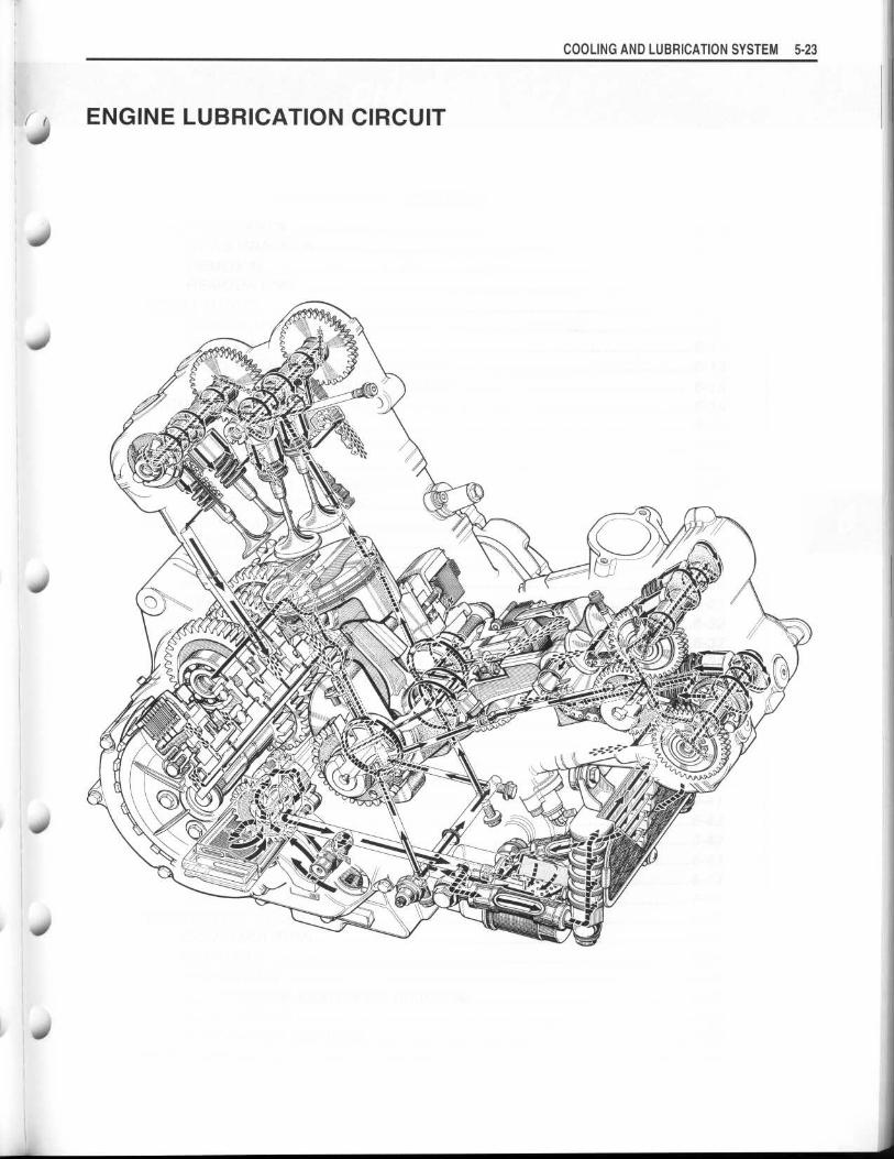
i ( ENGINE LUBRICATION CIRCUITS
./
COOLING AND LUBRICATION SYSTEM 5-23