ENGINE ASSEMBLY 1113-01 -...
21
01-3 ENGINE ASSEMBLY undefined 1113-01 1113-01 ENGINE ASSEMBLY GENERAL 1. DESCRIPTION AND OPERATION 1) Cleanliness and Care An automobile engine is a combination of many machined, honed, polished and lapped surfaces with tolerances that are measured in the ten-thousanths of an inch. When any internal engine parts are serviced, care and cleanliness are important. A liberal coating of enigne oil should be applied to friction areas during assembly, to protect and lubricate the surfaces on initial operation. Proper cleaning and protection of machined surfaces and friction areas is part of the repair procedure. This is considered standard shop practice even if not specifically stated. Whenever valve train components are removed for service, they should be kept in order. They should be installed in the same locations, and with the same mating surfaces, as when they were removed. Battery cables should be disconnected before any major work is performed on the engine. Failure to disconnect cables may result in damage to wire harness or other electrical parts.
-
Upload
truongdung -
Category
Documents
-
view
252 -
download
2
Transcript of ENGINE ASSEMBLY 1113-01 -...

01-3
ENGINE ASSEMBLYundefined
1113-01
1113-01 ENGINE ASSEMBLYGENERAL
1. DESCRIPTION AND OPERATION1) Cleanliness and CareAn automobile engine is a combination of many machined, honed, polished and lapped surfaces with tolerances that are measured in the ten-thousanths of an inch. When any internal engine parts are serviced, care and cleanliness are important. A liberal coating of enigne oil should be applied to friction areas during assembly, to protect and lubricate the surfaces on initial operation. Proper cleaning and protection of machined surfaces and friction areas is part of the repair procedure.This is considered standard shop practice even if not specifically stated.Whenever valve train components are removed for service, they should be kept in order. They should be installed in the same locations, and with the same mating surfaces, as when they were removed.Battery cables should be disconnected before any major work is performed on the engine. Failure to disconnect cables may result in damage to wire harness or other electrical parts.
01-4
undefined
1113-01
ENGINE ASSEMBLY
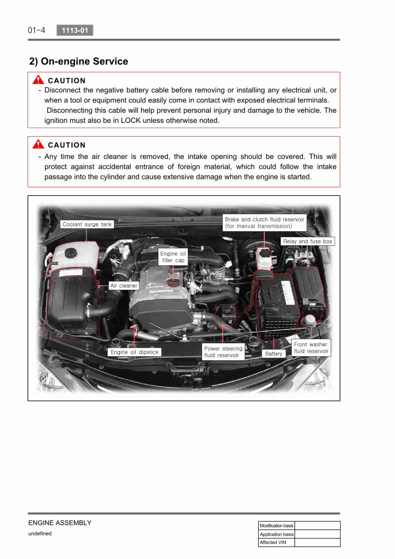
2) On-engine Service
Disconnect the negative battery cable before removing or installing any electrical unit, or when a tool or equipment could easily come in contact with exposed electrical terminals. Disconnecting this cable will help prevent personal injury and damage to the vehicle. The ignition must also be in LOCK unless otherwise noted.
-
Any time the air cleaner is removed, the intake opening should be covered. This will protect against accidental entrance of foreign material, which could follow the intake passage into the cylinder and cause extensive damage when the engine is started.
-

01-5
ENGINE ASSEMBLYundefined
1113-01
2. G23D ENGINE ASSEMBLYFront View
Rear View

01-6
undefined
1113-01
ENGINE ASSEMBLY
LH Side View
RH Side View

01-7
ENGINE ASSEMBLYundefined
1113-01
3. G23D ENGINE STRUCTUREFront View
Side View

01-8
undefined
1113-01
ENGINE ASSEMBLY
Front View▶
NO. FUNCTION NO. FUNCTION
1 HFM Sensor 12 Intake Manifold
2 Intake Air Duct 13 Cylinder Head
3 Cylinder Head Cover 14 Exhaust Manifold
4 Ignition Coi 15 Dipstick Guide Tube and Gauge
5 Spark Plug Connector 16 Connecting Rod
6 Fuel Distributor 17 Crankshaft
7 Injector 18 Engine Mounting Bracket
8 Exhaust Camshaft 19 Starter
9 Intake Camshaft 20 Crankcase
10 Valve Tappet 21 Oil Pump Sprocket
11 Intake Valve 22 Oil Pan
NO. FUNCTION NO. FUNCTION
23 Camshaft Adjuster 29 Oil Pump Drive Chain
24 Oil Filler Cap 30 Oil Strainer
25 Engine Hanger Bracket 31 Oil Pump
26 Cooling Fan and Viscous Clutch 32 Ring Gear and Flywheel of Drive Plate
27 Oil Filter 33 Piston
28 Timing Chain
Side View▶

01-9
ENGINE ASSEMBLYundefined
1113-01
4. DIAGNOSTIC INFORMATION AND PROCEDURE1) Oil Leak DiagnosisMost fluid oil leaks are easily located and repaired by visually finding the leak and replacing or repairing the necessary parts. On some occasions a fluid leak may be difficult to locate or repair. The following procedures may help you in locating and repairing most leaks.
Finding the Leak▶
Identify the fluid. Determine whether it is engine oil, automatic transmission fluid, power steering fluid, etc.Identify where the fluid is leaking from.
-
-After running the vehicle at normal operating temperature, park the vehicle over a large sheet of paper.Wait a few minutes.You should be able to find the approximate location of the leak by the drippings on the paper.
·
·
·
Visually check around the suspected component.Check around all the gasket mating surfaces for leaks. A mirror is useful for finding leaks in areas that are hard to reach.If the leak still cannot be found, it may be necessary to clean the suspected area with a degreaser, steam or spray solvent.
-
-
Clean the area well.Dry the area.Operate the vehicle for several miles at normal operating temperature and varying speeds.After operating the vehicle, visually check the suspected component.If you still cannot locate the leak, try using the powder or black light and dye method.
·
·
·
·
·
Clean the suspected area.Apply an aerosol-type powder (such as foot powder) to the suspected area.Operate the vehicle under normal operating conditoins.Visually inspect the suspected component. You should be able to trace the leak path over the white powder surface to the source.
----
Powder Method▶

01-10
undefined
1113-01
ENGINE ASSEMBLY
Black Light and Dye Method▶
A dye and light kit is available for finding leaks, Refer to the manufacturer's directions when using the kit.
Pour the specified amount of dye into the engine oil fill tube.Operate the vehicle normal operating conditions as directed in the kit.Direct the light toward the suspected area. The dyed fluid will appear as a yellow path leading to the source.
---
Once the origin of the leak has been pinpointed and traced back to its source, the cause of the leak must be determined in order for it to be repaired properly. If a gasket is replaced, but the sealing flange is bent, the new gasket will not repair the leak. The bent flange must be repaired also. Before attempting to repair a leak, check for the following conditions and correct them as they may cause a leak.
Repairing the Leak▶
Gaskets▶
The fluid level/pressure is too high.The crankcase ventilation system is malfunctioning.The seal bore is damaged (scratched, burred or nicked).The seal is damaged or worn.Improper installation is evident.There are cracks in the components.The shaft surface is scratched, nicked or damaged.A loose or worn bearing is causing excess seal wear.
--------

01-11
ENGINE ASSEMBLYundefined
1113-01
2) Compression Pressure Test
Standard Service Data▶
A9912 0012B (001 589 76 21 00) Compression Pressure Tester-
Measuring Procedure▶
Warm the engine up to normal operating temperature.Remove the spark plugs using the spark plug wrench.Place the diagram sheet to compression pressure tester A9912 0012B (001 589 76 21 00).Connect the adaptor to compression pressure tester A9912 0012B (001 589 76 21 00) and install it into the spark plug hole.Crank the engine approx. eight revolutions by using the start motor.Compare the measurements of compression pressure tester A9912 0012B (001 589 76 21 00) with the specifications.Measure the compression pressure of the other cylinders in the same way.If measured value is not within the specifications, perform the cylinder pressure leakage test.
---
-
--
--
Discharge the combustion residues in the cylinders before testing the compression pressure.Apply the parking brake before cranking the engine.
-
-

01-12
undefined
1113-01
ENGINE ASSEMBLY
3) Cylinder Pressure LeakageTest
Permissible Pressure Leakage▶
At Whole Engine Max. 25 %
At Valve and Cylinder Head Gasket Max. 10 %
At Piston and Piston Ring Max. 20 %
OT (TDC) 1, 4
UT (BDC 180 °) 2, 3
Cylinder Number▶
Cylinder Number▶
Cylinder Pressure Leakage Tester
Bosch, EFAW210ASun, CLT 228

01-13
ENGINE ASSEMBLYundefined
1113-01
Leakage Test▶
Warm the engine up to normal operating temperature.Disconnect the negative battery cable.Remove the spark plugs.Check the coolant level by opening the coolant reservoir cap and replenish if insufficient.Open the engine oil filler cap.Connect the tester to air pressure line and adjust the scale of tester.Install the connecting hose to spark plug hole.Position the piston of No.1 cylinder at TDC by rotating the crankshaft.Connect the connecting hose to tester and measure the leakage volume after blowing up 5 bar of compressed air.
---------
Measure the leakage volume in the completely opening condition of throttle valve bypulling the acceleration cable.
-
Perform the pressure test according to the firing order.-
Firing Order: 1 - 3 - 4 - 2-
Compare the leakage pressure with the specifications.-

01-14
undefined
1113-01
ENGINE ASSEMBLY
5. GENERAL DIAGNOSIS
01-15
ENGINE ASSEMBLYundefined
1113-01
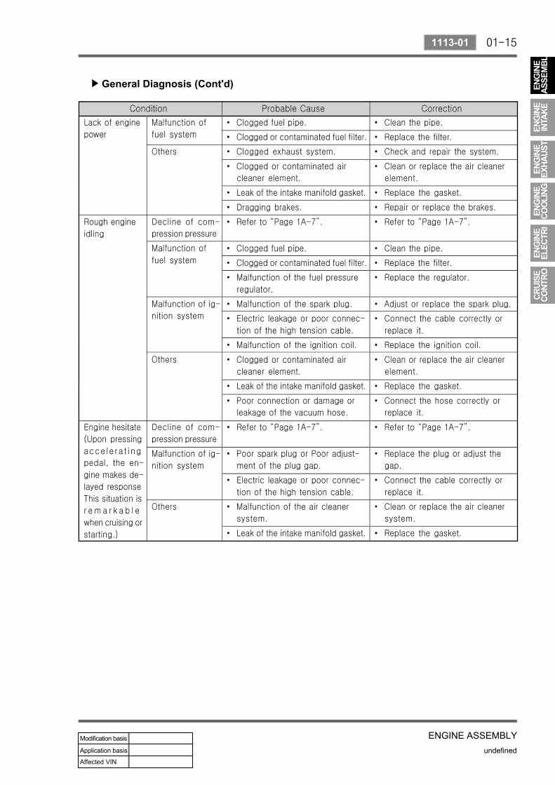
General Diagnosis (Cont'd)▶

01-16
undefined
1113-01
ENGINE ASSEMBLY
General Diagnosis (Cont'd)▶

01-17
ENGINE ASSEMBLYundefined
1113-01
General Diagnosis (Cont'd)▶

01-18
undefined
1113-01
ENGINE ASSEMBLY
General Diagnosis (Cont'd)▶

01-19
ENGINE ASSEMBLYundefined
1113-01
6. SPECIFICATIONS1) Engine Specifications
MSE : Engine Control Module3.53D : 4 Cylinder Version

01-20
undefined
1113-01
ENGINE ASSEMBLY
2) Fastener Tightening Specifications

01-21
ENGINE ASSEMBLYundefined
1113-01
Fastener Tightening Specifications (Cont'd)▶

01-22
undefined
1113-01
ENGINE ASSEMBLY
2) Performance Curve