ENE 240 Class07 - KMUTTwebstaff.kmutt.ac.th/~werapon.chi/M2_3/1_2017/ENE_240_Class07.… · Phasor...
29
1 1 2
Transcript of ENE 240 Class07 - KMUTTwebstaff.kmutt.ac.th/~werapon.chi/M2_3/1_2017/ENE_240_Class07.… · Phasor...
1
1
2
2
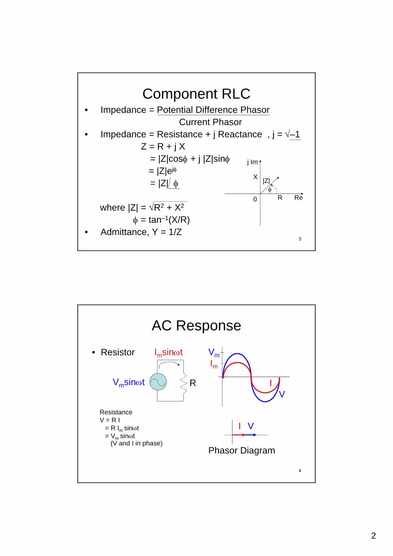
Component RLC• Impedance = Potential Difference Phasor
Current PhasorI d R i t + j R t j 1• Impedance = Resistance + j Reactance , j =–1
Z = R + j X= |Z|cos + j |Z|sin= |Z|ej
= |Z|
j Im
|Z|
X
3
where |Z| = R2 + X2
= tan–1(X/R)• Admittance, Y = 1/Z
Re0
R
AC Response
• Resistor Imsint Vm
I
Vmsint R
I V
ResistanceV = R I
V
Im
I
4
I V
Phasor Diagram
= R Im sint= Vm sint
(V and I in phase)

3
AC Response (Cont’d)• Capacitor is a passive component storing the
energy in an electric field charged by the voltage across the dielectric.
I = C dV/dt Vm
Capacitive ReactanceI = dq/dt = C dV/dtV = 1/C Imsint dt + V0
1/ C I tI
V = Vmsin(t)C
I C dV/dt= Imsin(t + /2)
m
V
Im I
/2
0
= –1/C Imcost= 1/C Imsin(t–/2)= XCIm sin(t–/2)= Vmsin(t–/2)(V lags I by 90)
XC = 1/C = 1/2fC = /2C , Higher f, Lower XC (Lowpass Filter) 5
V
Phasor Diagram
AC Response (Cont’d)• Note that capacitive reactance is an opposition to
the change of voltage across an element.
• There are two choices in the literature for defining greactance for a capacitor. One is to use a uniform notion of reactance as the imaginary part of impedance, in which case the reactance of a capacitor is a negative number: XC = – 1/C and ZC = j XC = – j/C .
• Another choice is to define capacitive reactance as a positive number, however, one needs to remember to add a negative sign for the impedance of a capacitor: XC = 1/C and ZC = – j XC = 1/jC . 6
4
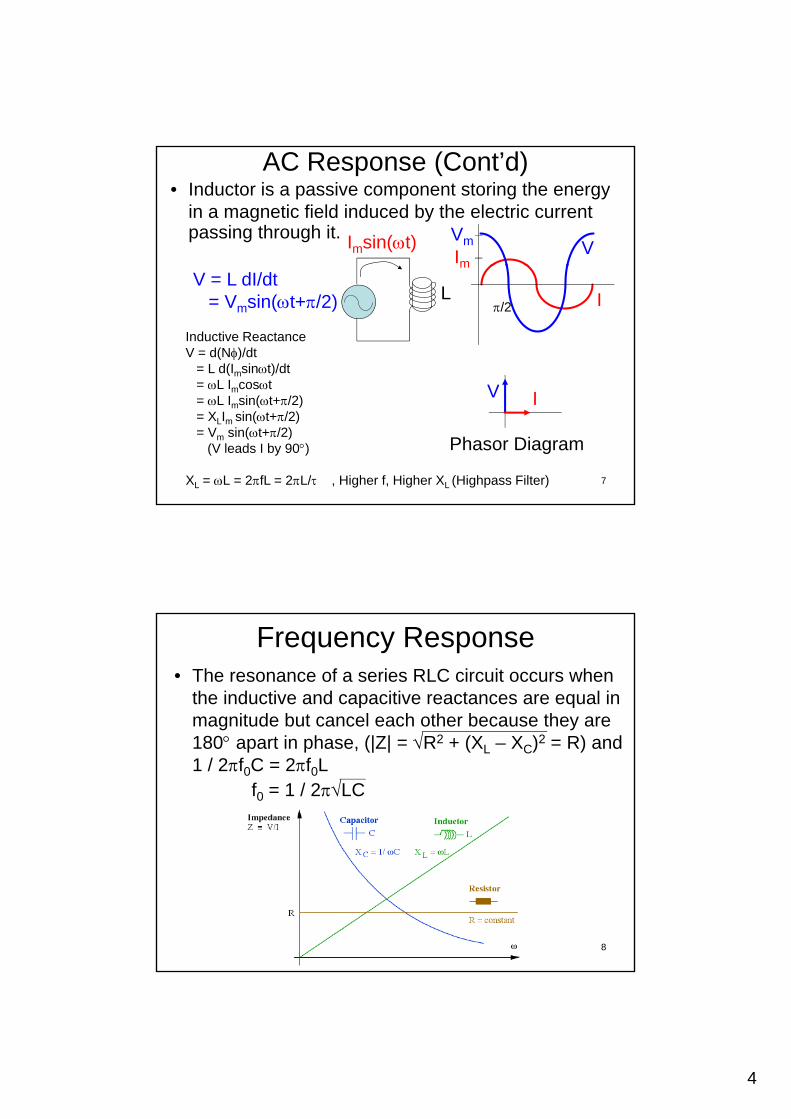
AC Response (Cont’d)• Inductor is a passive component storing the energy
in a magnetic field induced by the electric current passing through it. Imsin(t) Vm VImV = L dI/dt
= Vmsin(t+/2) L
V
Inductive ReactanceV = d(N)/dt
= L d(Imsint)/dt= L I cost
m
I/2
7
IV
Phasor Diagram
= L Imcost= L Imsin(t+/2)= XLIm sin(t+/2)= Vm sin(t+/2)
(V leads I by 90)
XL = L = 2fL = 2L/ , Higher f, Higher XL (Highpass Filter)
Frequency Response• The resonance of a series RLC circuit occurs when
the inductive and capacitive reactances are equal in magnitude but cancel each other because they are
180 apart in phase, (|Z| = R2 + (XL – XC)2 = R) and1 / 2f0C = 2f0L
f0 = 1 / 2LC
8
5
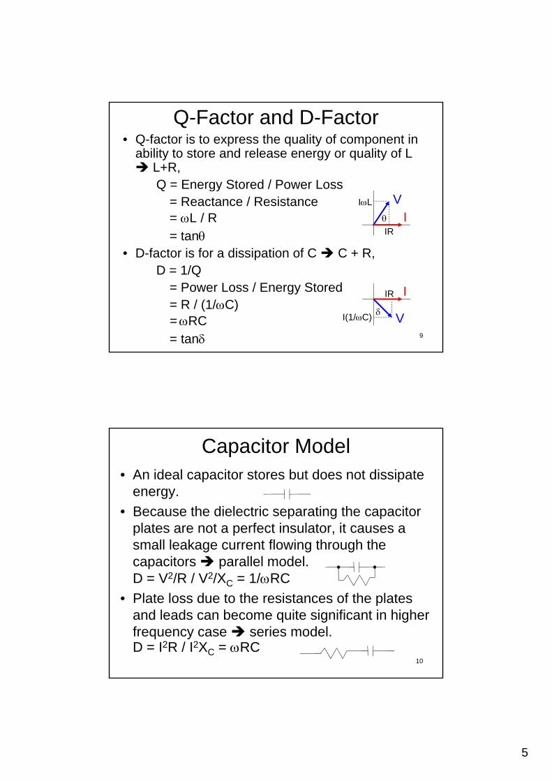
• Q-factor is to express the quality of component in ability to store and release energy or quality of L L+R,
Q = Energy Stored / Power Loss
Q-Factor and D-Factor
Q = Energy Stored / Power Loss= Reactance / Resistance= L / R= tan
• D-factor is for a dissipation of C C + R,D = 1/Q
IR
IL
IV
9
D = 1/Q= Power Loss / Energy Stored= R / (1/C)= RC= tan
IR
I(1/C)
I
V
Capacitor Model• An ideal capacitor stores but does not dissipate
energy.
• Because the dielectric separating the capacitor• Because the dielectric separating the capacitor plates are not a perfect insulator, it causes a small leakage current flowing through the capacitors parallel model. D = V2/R / V2/XC = 1/RC
Pl t l d t th i t f th l t• Plate loss due to the resistances of the plates and leads can become quite significant in higher frequency case series model.D = I2R / I2XC = RC
10

6
Inductor Model• An ideal inductor stores but does not dissipate
energy.
• Time varying current in a ferromagnetic• Time-varying current in a ferromagnetic inductor, which causes a time-varying magnetic field in its core, causes energy losses in the core material that are dissipated as heat parallel model. Q = V2/X / V2/R = R/LQ = V2/XL / V2/R = R/L
• Resistance of the wire series model.Q = I2XL / I2R = L/R
11
AC Bridge
Z1 Z
B Balanced Bridge,I |Z | = I |Z | Z1 Z2
Z3 Z4
DetectorI1
I2
AC
D
I1 |Z1| 1 = I2 |Z3| 3
I1 |Z2| 2 = I2 |Z4| 4
|Z1|/|Z2| 1–2 = |Z3|/|Z4| 3–4
12
D | 1| | 2| 1 2 | 3| | 4| 3 4
R1+jX1 = R3+jX3
R2+jX2 R4+jX4Wheatstone Bridge

7
Inductance MeasurementThere is no pure components, e.g. an inductor can
be considered to be a pure inductance (L4) in series with a pure resistance (R4).
Maxwell-Wien Bridge (for medium Q = 1-10)
Impedances,1/Z1 = 1/R1 + 1/(1/jC1)
Z1 = R1 / (1+jR1C1)
R1 R2
DC1
13
Z2 = R2
Z3 = R3
Z4 = R4 + jL4R3
R4
D
L4
1
Maxwell-Wien Bridge (Cont’d)Balanced bridge,
Z1 / Z2 = Z3 / Z4
Z4 = Z2Z3 / Z1
R4+jL4 = R2 R3 (1+jR1C1)/R1
= R2R3/R1 + jR2R3C1
Real part: R4 = R2R3/R1
Imagination part: L4 = R2R3C1
James Clerk Maxwell (1831-1879), a Scottish
scientist in the field of mathematical physics.
14
g p 4 2 3 1
The balancing is independent of frequency.Adjust R1 and R2 to get the bridge balanced (Null)
Q = L4/R4 = (R2R3C1)/(R2R3/R1) = R1C1

8
Hay Bridge
C1
I d
For high Q 10
R1R2
R3
D
L4
Impedances, Z1 = R1 + 1/jC1
= R1 – j/C1
Z2 = R2
Z = R
15
R3R4
4 Z3 = R3
Z4 = R4 + jL4
Hay Bridge (Cont’d)Balanced bridge,
Z4 = Z2Z3 / Z1
R4+jL4 = R2 R3 / (R1 – j/C1)
(R R L /C ) j ( R L R / C ) R R(R1R4 + L4/C1) + j (R1L4 – R4/C1) = R2R3
Imagination part: R1L4 = R4/C1
L4 = R4 / 2R1C1
Real part: R1R4 + L4/C1 = R2R3
R R + R /2R C 2 = R R
16
R1R4 + R4/2R1C12 = R2R3
R4 ( R1 + 1/2R1C12 ) = R2R3
R4 (2R12C1
2 + 1)/(2R1C12) = R2R3
R4 = (2R1R2R3C12) / (2R1
2C12 + 1)
L4 = (R2R3C1) / (2R12C1
2 + 1)
9
Hay Bridge (Cont’d)
Q = L4/R4
1/ R C= 1/R1C1
Therefore, L4 = (R2R3C1) / ( (1/Q2) + 1 )
R2R3C1 if Q 10
17
and R4 2R1R2R3C12
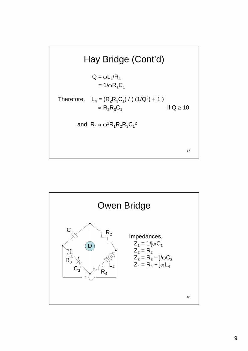
Owen Bridge
C R2
R3
D
L4
C1
C
Impedances, Z1 = 1/jC1
Z2 = R2
Z3 = R3 – j/C3
Z4 = R4 + jL4
18
R4
4C34 4 j 4
10
Owen Bridge (Cont’d)
Balanced bridge,
Z4 = Z2Z3 / Z14 2 3 1
R4+jL4 = R2 (R3 – j/C3) jC1
= R2C1/C3 + jR2R3C1
Real part: R4 = R2C1/C3
I i ti t L R R C
19
Imagination part: L4 = R2R3C1
The balancing is independent of frequency.
Q = L4/R4 = R2R3C1C3 / R2C1 = R3C3
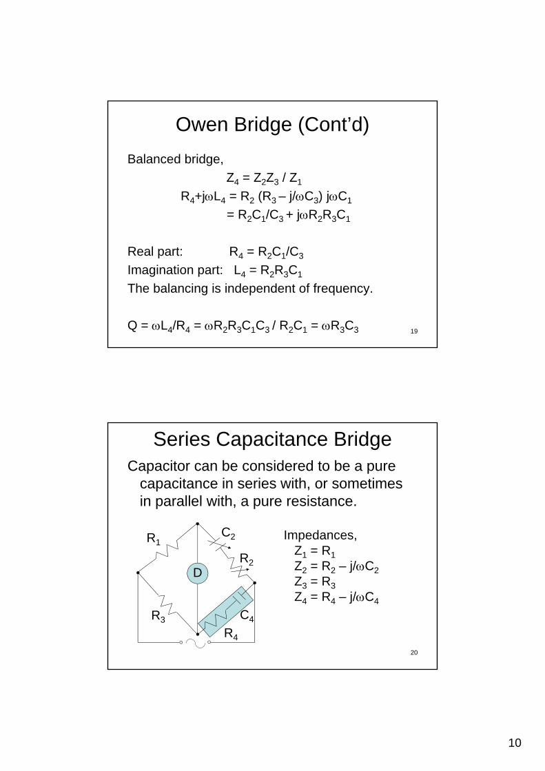
Series Capacitance BridgeCapacitor can be considered to be a pure
capacitance in series with, or sometimes in parallel with, a pure resistance.in parallel with, a pure resistance.
R2D
R1C2 Impedances,
Z1 = R1
Z2 = R2 – j/C2
Z3 = R3
20
R3
R4
C4
3 3
Z4 = R4 – j/C4
11
Series Capacitance Bridge (Cont’d)
Balanced bridge,
Z4 = Z2Z3 / Z14 2 3 1
R4 – j/C4 = (R2 – j/C2) R3 / R1
= R2R3/R1 – j(R3/C2R1)
Real part: R4 = R2R3/R1
I i ti t C C R /R
21
Imagination part: C4 = C2R1/R3
Used for low D = 0.001-0.1
D = 1/Q = R4C4 = R2C2
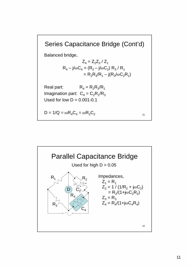
Parallel Capacitance Bridge
I d
Used for high D > 0.05
R2
R
R4
D
R1
C2
Impedances, Z1 = R1
Z2 = 1 / (1/R2 + jC2)= R2/(1+jC2R2)
Z3 = R3
Z = R /(1+jC R )
22
R3C4
Z4 = R4/(1+jC4R4)
12
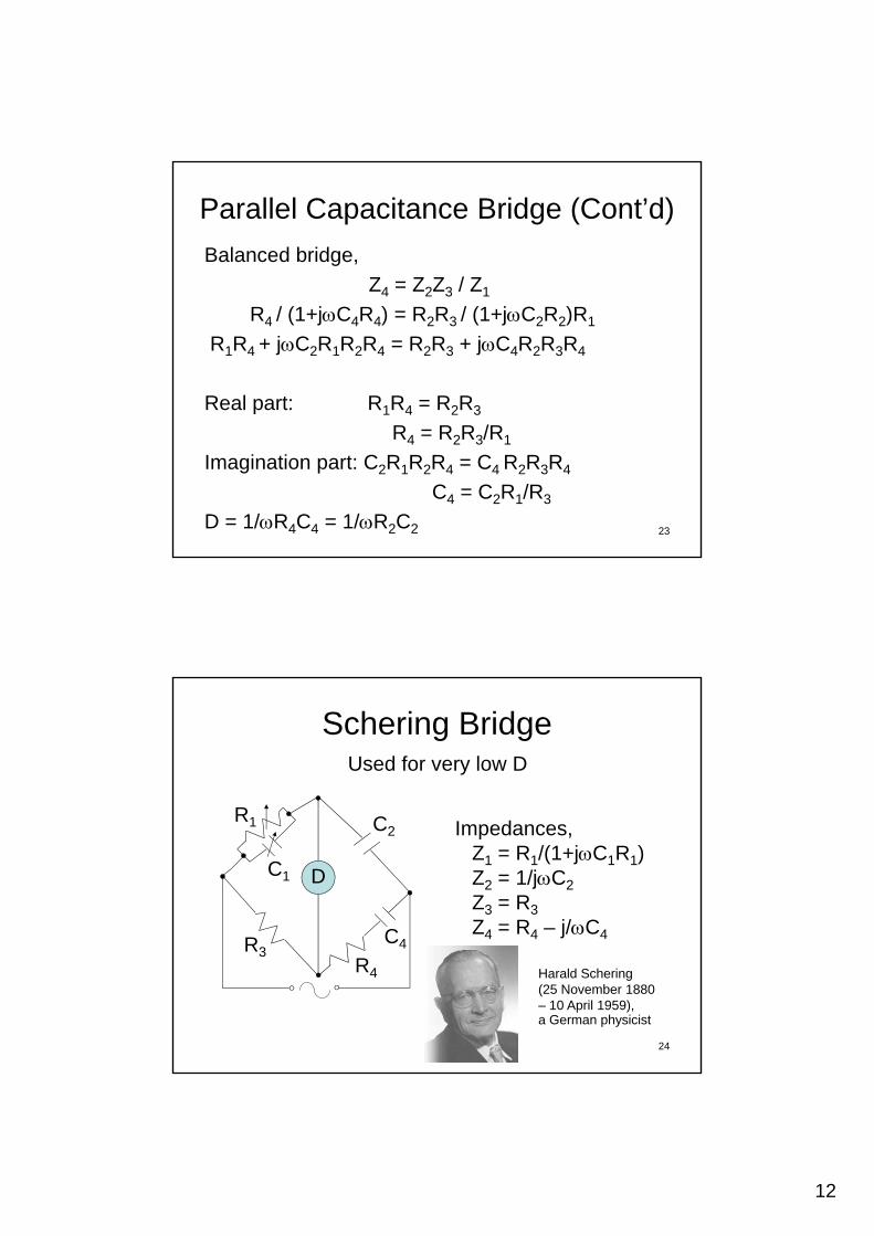
Parallel Capacitance Bridge (Cont’d)
Balanced bridge,
Z4 = Z2Z3 / Z14 2 3 1
R4 / (1+jC4R4) = R2R3 / (1+jC2R2)R1
R1R4 + jC2R1R2R4 = R2R3 + jC4R2R3R4
Real part: R1R4 = R2R3
R R R /R
23
R4 = R2R3/R1
Imagination part: C2R1R2R4 = C4 R2R3R4
C4 = C2R1/R3
D = 1/R4C4 = 1/R2C2
Schering Bridge
R
Used for very low D
R
D
C4
C2R1
C1
Impedances, Z1 = R1/(1+jC1R1)Z2 = 1/jC2
Z3 = R3
Z4 = R4 – j/C4
24
R3R4
C4
Harald Schering (25 November 1880 – 10 April 1959), a German physicist
13
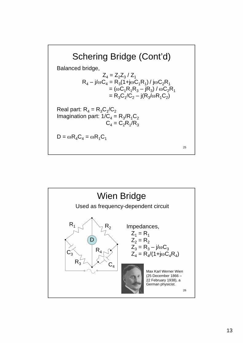
Schering Bridge (Cont’d)Balanced bridge,
Z4 = Z2Z3 / Z1
R j/C = R (1+jC R ) / jC RR4 – j/C4 = R3(1+jC1R1) / jC2R1
= (C1R1R3 – jR3) / C2R1
= R3C1/C2 – j(R3/R1C2)
Real part: R4 = R3C1/C2
Imagination part: 1/C4 = R3/R1C2
25
g p 4 3 1 2
C4 = C2R1/R3
D = R4C4 = R1C1
Wien Bridge
RR I d
Used as frequency-dependent circuit
R2
R
R4
D
R1
C3
Impedances, Z1 = R1
Z2 = R2
Z3 = R3 – j/C3
Z4 = R4/(1+jC4R4)
26
R3 C4Max Karl Werner Wien (25 December 1866 –22 February 1938), a German physicist.

14
Wien Bridge (Cont’d)Balanced bridge,
Z4 = Z2Z3 / Z1
R4 / (1+jC4R4) = R2(R3 – j/C3) / R1
R R /R = R + R C /C + j(C R R 1/C )R1R4/R2 = R3 + R4C4/C3 + j(C4R3R4 – 1/C3)
Imagination part: C4R3R4 = 1/C3
C4R4 = 1/2C3R3
Real part: R1R4/R2= R3 + R4C4/C3
R4 = (R3R2C3 + R2R4C4)/ R1C32
27
= (R3R2C3 + R2/2C3R3) / R1C3
= R2(2C32R3
2 + 1) / (2C32R1R3)
and C4 = 1/2C3R3R4
= C3R1 / R2(2C32R3
2 + 1) D = 1/R4C4 = R3C3
Wien Bridge OscillatorA type of electronic oscillator that generates sine waves
with a large range of frequencies. At balance, Imagination part: C4R4 = 1/2C3R3Imagination part: C4R4 = 1/ C3R3
2 = 1 / R3R4C3C4
f = 1/ 2R3R4C3C4
If R3 = R4 = R and C3 = C4 = C
28
Then f = 1/ 2RC
15
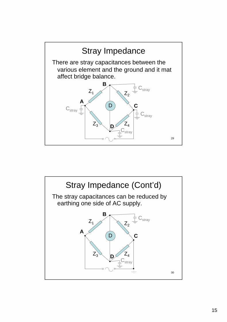
Stray ImpedanceThere are stray capacitances between the
various element and the ground and it mat affect bridge balanceaffect bridge balance.
Z1 Z2
A
B
CDCstray
Cstray
29
Z3 Z4D
Cstray
stray
Cstray
Stray Impedance (Cont’d)The stray capacitances can be reduced by
earthing one side of AC supply.
Z1 Z2
A
B
CD
Cstray
30
Z3 Z4DCstray

16
Stray Impedance (Cont’d)The minimize stray capacitances between
the detector terminals and earth, Wagner earth is used.
ZB
Z1 Z2
Z Z
ACD
To ensuring that the points B and
31
Z3 Z4
D
Z5 Z6
D of a balanced bridge are at ground potential
Ex1. Maxwell-Wein Bridge
Impedances, = 2f
= 2(1k)
D
L4
= 2000 rad/sZ1 = R1 / (1+jR1C1)
= 1k 1+j(2000)(1k)(0.5)
= 92 – j289
32
R4 92 j289
Z2 = R2 = 600 Z3 = R3 = 400 Z4 = R4 + jL4
= R4 + j2000L4
f = 1kHz
17
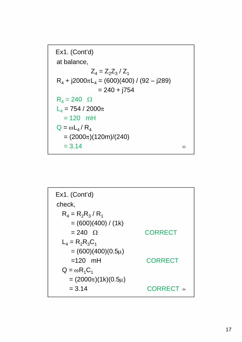
at balance,
Z4 = Z2Z3 / Z1
R4 + j2000L4 = (600)(400) / (92 – j289)
Ex1. (Cont’d)
R4 + j2000L4 = (600)(400) / (92 – j289)
= 240 + j754
R4 = 240 L4 = 754 / 2000
= 120 mH= 120 mH
Q = L4 / R4
= (2000)(120m)/(240)
= 3.14 33
check,
R4 = R2R3 / R1
= (600)(400) / (1k)
Ex1. (Cont’d)
= (600)(400) / (1k)
= 240 CORRECT
L4 = R2R3C1
= (600)(400)(0.5)
=120 mH CORRECT=120 mH CORRECT
Q = R1C1
= (2000)(1k)(0.5)
= 3.14 CORRECT 34
18
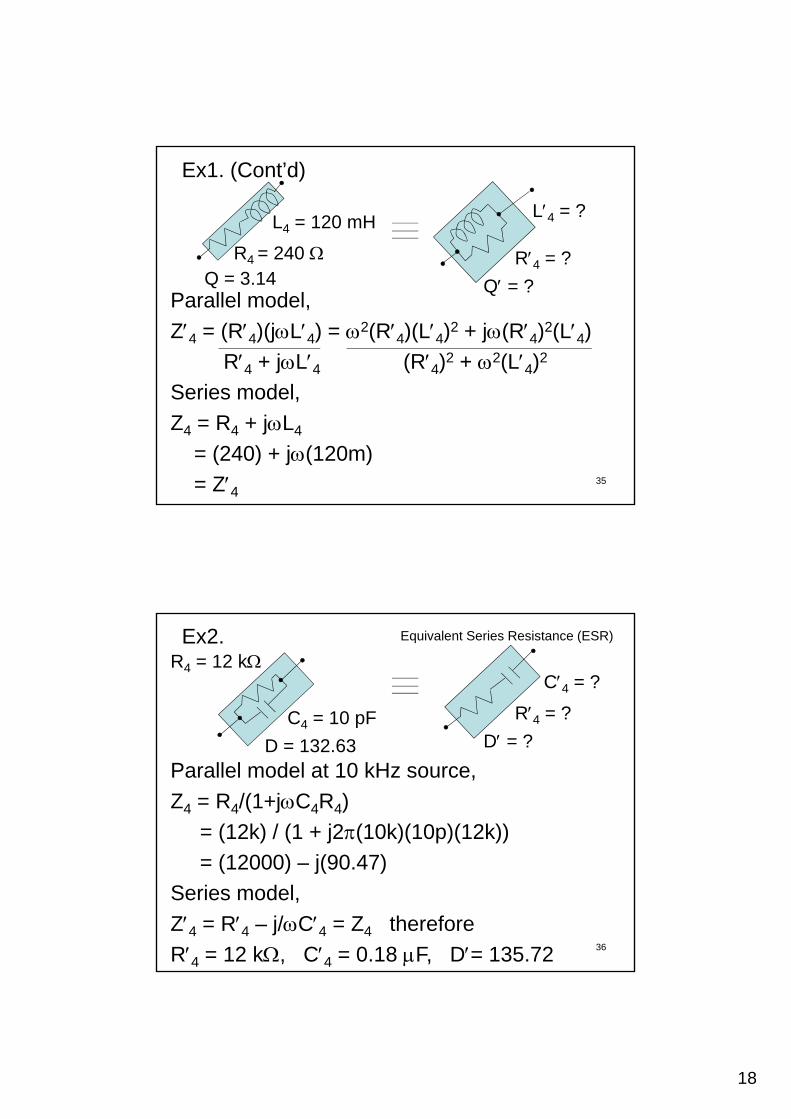
R4 = ?R4 = 240
L4 = 120 mHL4 = ?
Ex1. (Cont’d)
Parallel model,
Z4 = (R4)(jL4) = 2(R4)(L4)2 + j(R4)2(L4) R4 + jL4 (R4)2 + 2(L4)2
S i d l
4Q = 3.14 Q = ?
Series model,
Z4 = R4 + jL4
= (240) + j(120m)
= Z4 35
R4 = 12 k
C4 = 10 pF
Ex2.
R4 = ?
C4 = ?
Equivalent Series Resistance (ESR)
D = ?D = 132.63Parallel model at 10 kHz source,
Z4 = R4/(1+jC4R4)
= (12k) / (1 + j2(10k)(10p)(12k))
36
= (12000) – j(90.47)
Series model,
Z4 = R4 – j/C4 = Z4 therefore
R4 = 12 k, C4 = 0.18 F, D= 135.72
19
37
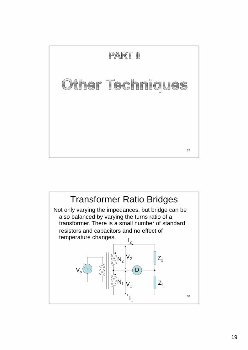
Transformer Ratio BridgesNot only varying the impedances, but bridge can be
also balanced by varying the turns ratio of a transformer. There is a small number of standard
i t d it d ff t fresistors and capacitors and no effect of temperature changes.
Z2
I2
N2V2
38
Vs D
Z1
I1
N1 V1
20
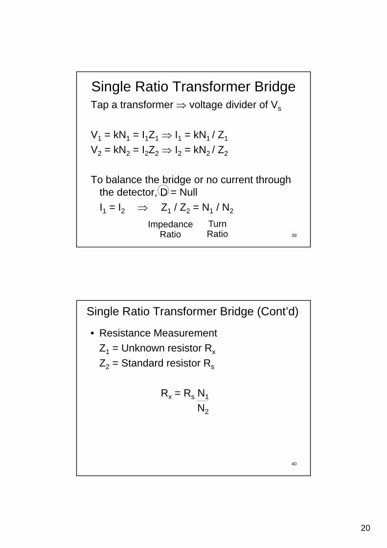
Single Ratio Transformer BridgeTap a transformer voltage divider of Vs
V1 = kN1 = I1Z1 I1 = kN1 / Z1
V2 = kN2 = I2Z2 I2 = kN2 / Z2
To balance the bridge or no current through th d t t D N ll
39
the detector, D = Null
I1 = I2 Z1 / Z2 = N1 / N2
ImpedanceRatio
TurnRatio
Single Ratio Transformer Bridge (Cont’d)
• Resistance Measurement
Z1 = Unknown resistor Rx
Z2 = Standard resistor Rs
Rx = Rs N1
N2
40
21
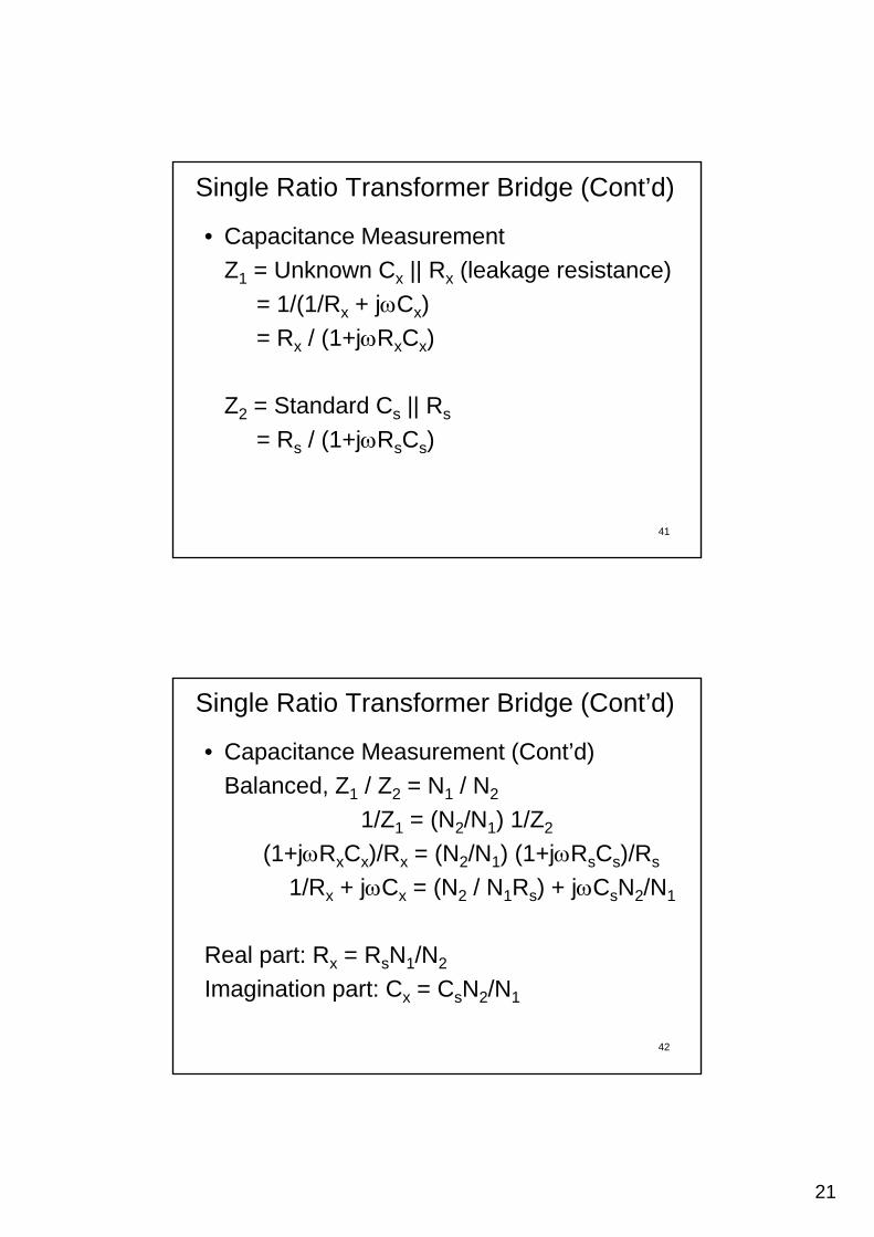
Single Ratio Transformer Bridge (Cont’d)
• Capacitance Measurement
Z1 = Unknown Cx || Rx (leakage resistance)
= 1/(1/Rx + jCx)
= Rx / (1+jRxCx)
Z2 = Standard Cs || Rs
41
= Rs / (1+jRsCs)
Single Ratio Transformer Bridge (Cont’d)
• Capacitance Measurement (Cont’d)
Balanced, Z1 / Z2 = N1 / N2
1/Z1 = (N2/N1) 1/Z2
(1+jRxCx)/Rx = (N2/N1) (1+jRsCs)/Rs
1/Rx + jCx = (N2 / N1Rs) + jCsN2/N1
42
Real part: Rx = RsN1/N2
Imagination part: Cx = CsN2/N1
22
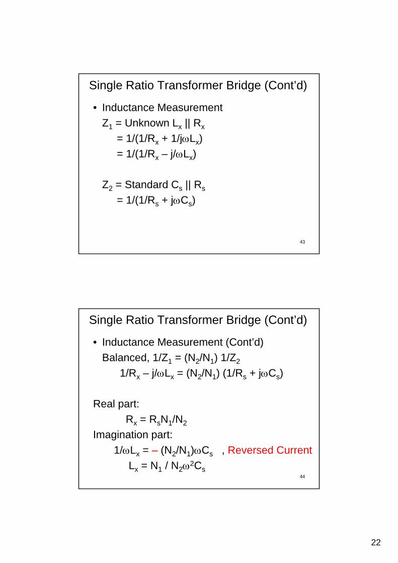
Single Ratio Transformer Bridge (Cont’d)
• Inductance Measurement
Z1 = Unknown Lx || Rx
= 1/(1/Rx + 1/jLx)
= 1/(1/Rx – j/Lx)
Z2 = Standard Cs || Rs
43
= 1/(1/Rs + jCs)
Single Ratio Transformer Bridge (Cont’d)
• Inductance Measurement (Cont’d)
Balanced, 1/Z1 = (N2/N1) 1/Z2
1/Rx – j/Lx = (N2/N1) (1/Rs + jCs)
Real part:
Rx = RsN1/N2
44
Imagination part:
1/Lx = – (N2/N1)Cs , Reversed Current
Lx = N1 / N22Cs

23
Double Ratio Transformer BridgeTo measure the impedance of components in Situ.
Z1
I1
Vs DZ2
N2
N1 V2
V1n1
n2
45
I1 = V1 / Z1 = k(N1+N2)/Z1
I2 = V2 / Z2 = kN2/Z2
I2
Double Ratio Transformer Bridge (Cont’d)
Balanced, null current or zero magnetic flux,
n I = n In1I1 = n2I2n1(N1+N2)/Z1 = n2N2/Z2
Z1 = Z2 n1(N1+N2)
n2N2
46
24
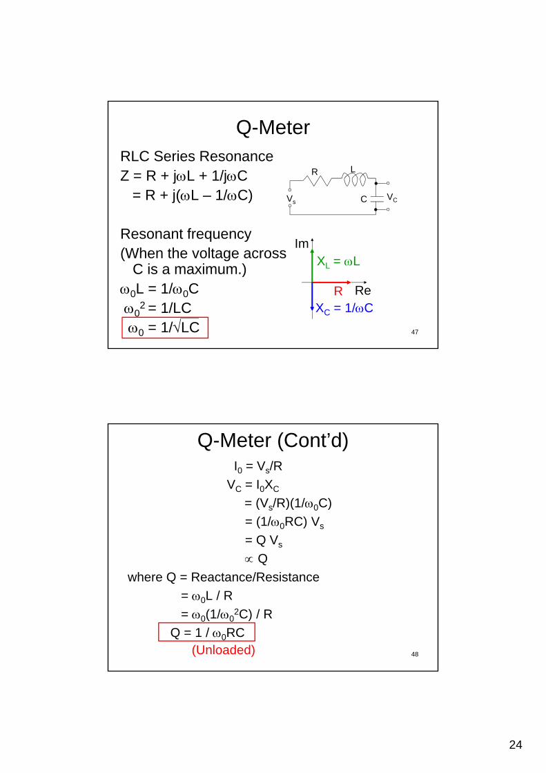
Q-MeterRLC Series ResonanceZ = R + jL + 1/jC R L
= R + j(L – 1/C)
Resonant frequency(When the voltage across
C is a maximum )
CVsVC
XL = LIm
47
C is a maximum.)0L = 1/0C0
2 = 1/LC0 = 1/LC
RXC = 1/C
L
Re
Q-Meter (Cont’d)I0 = Vs/R
VC = I0XC
= (Vs/R)(1/0C) (Vs/R)(1/0C)
= (1/0RC) Vs
= Q Vs
Q
where Q = Reactance/Resistance
48
= 0L / R
= 0(1/02C) / R
Q = 1 / 0RC(Unloaded)
25
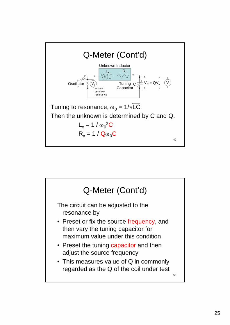
Q-Meter (Cont’d)
RxLx
Unknown Inductor
Tuning to resonance, 0 = 1/LC
CVsVC = QVs
across very lowresistance
Oscillator TuningCapacitor
V
49
Then the unknown is determined by C and Q.
Lx = 1 / 02C
Rx = 1 / Q0C
Q-Meter (Cont’d)
The circuit can be adjusted to the resonance byresonance by
• Preset or fix the source frequency, and then vary the tuning capacitor for maximum value under this condition
• Preset the tuning capacitor and then
50
g padjust the source frequency
• This measures value of Q in commonly regarded as the Q of the coil under test
26
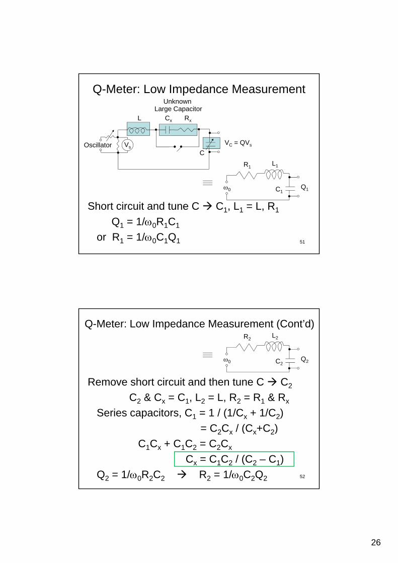
Q-Meter: Low Impedance Measurement
RxL
Unknown Large Capacitor
Cx
CVs
VC = QVsOscillator
R1L1
C10 Q1
51
Short circuit and tune C C1, L1 = L, R1
Q1 = 1/0R1C1
or R1 = 1/0C1Q1
Q-Meter: Low Impedance Measurement (Cont’d)R2
L2
C20 Q2
Remove short circuit and then tune C C2
C2 & Cx = C1, L2 = L, R2 = R1 & Rx
Series capacitors, C1 = 1 / (1/Cx + 1/C2)
= C C / (C +C )
52
= C2Cx / (Cx+C2)
C1Cx + C1C2 = C2Cx
Cx = C1C2 / (C2 – C1)
Q2 = 1/0R2C2 R2 = 1/0C2Q2
27
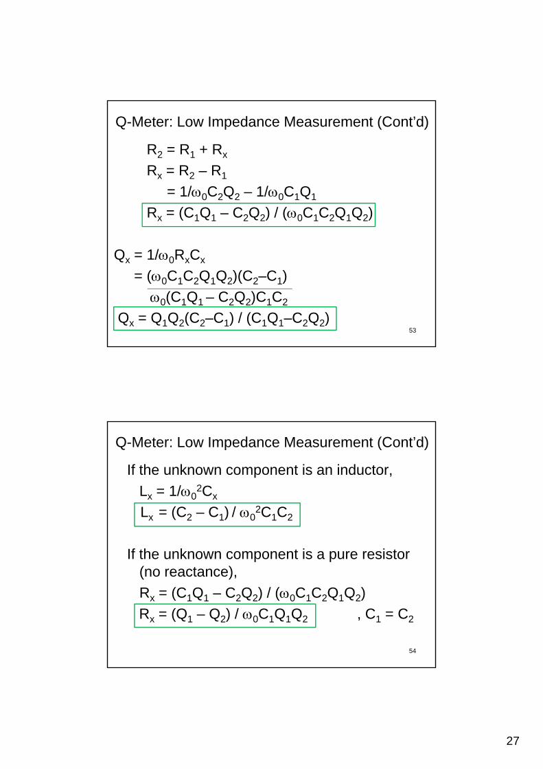
Q-Meter: Low Impedance Measurement (Cont’d)
R2 = R1 + Rx
Rx = R2 – R1
= 1/0C2Q2 – 1/0C1Q1
Rx = (C1Q1 – C2Q2) / (0C1C2Q1Q2)
Qx = 1/0RxCx
53
= (0C1C2Q1Q2)(C2–C1)
0(C1Q1 – C2Q2)C1C2
Qx = Q1Q2(C2–C1) / (C1Q1–C2Q2)
If the unknown component is an inductor,
Lx = 1/02Cx
Q-Meter: Low Impedance Measurement (Cont’d)
Lx = (C2 – C1) / 02C1C2
If the unknown component is a pure resistor (no reactance),
54
Rx = (C1Q1 – C2Q2) / (0C1C2Q1Q2)
Rx = (Q1 – Q2) / 0C1Q1Q2 , C1 = C2
28
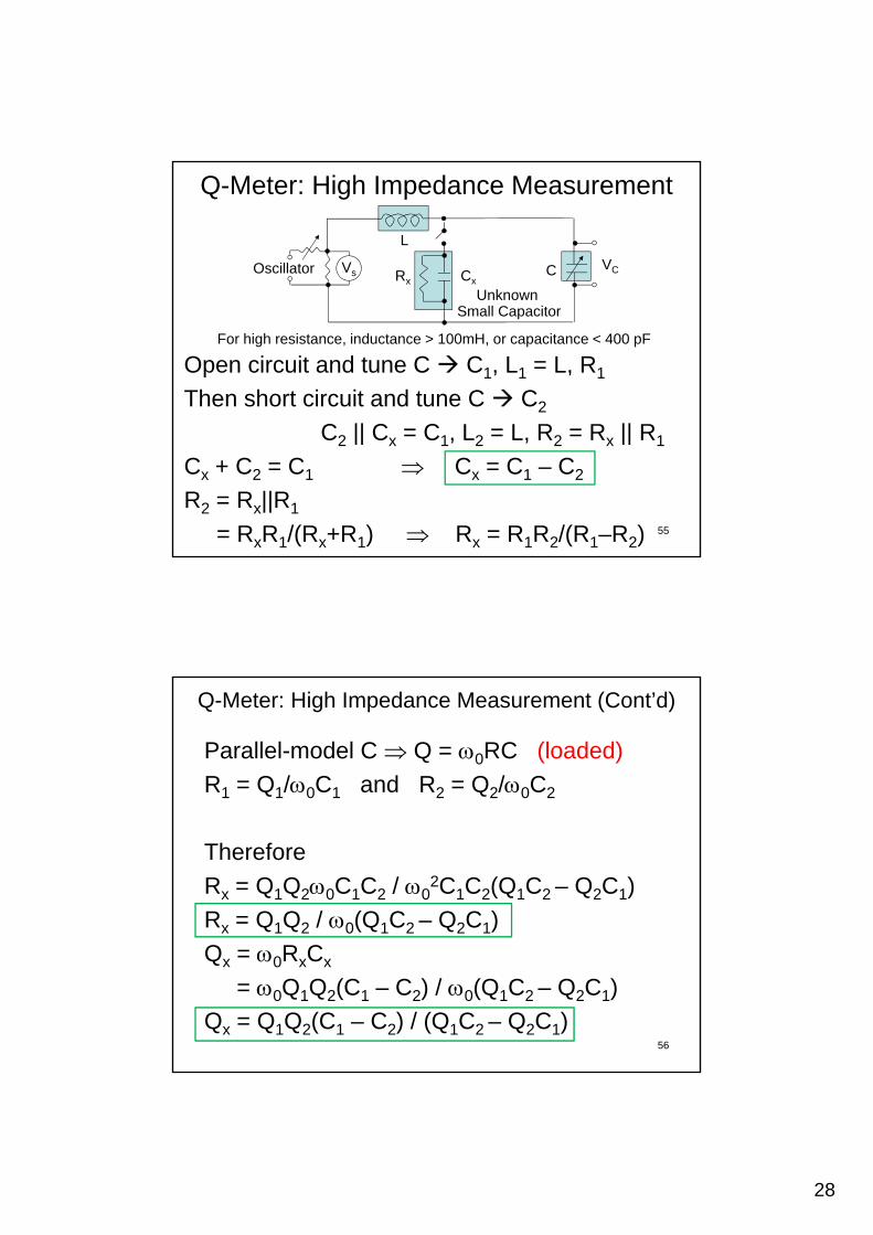
Q-Meter: High Impedance Measurement
Rx
L
CVsVCOscillator Cx
Unknown
Open circuit and tune C C1, L1 = L, R1
Then short circuit and tune C C2
C || C C L L R R || R
For high resistance, inductance > 100mH, or capacitance < 400 pF
Unknown Small Capacitor
55
C2 || Cx = C1, L2 = L, R2 = Rx || R1
Cx + C2 = C1 Cx = C1 – C2
R2 = Rx||R1
= RxR1/(Rx+R1) Rx = R1R2/(R1–R2)
Parallel-model C Q = 0RC (loaded)
R1 = Q1/0C1 and R2 = Q2/0C2
Q-Meter: High Impedance Measurement (Cont’d)
Therefore
Rx = Q1Q20C1C2 / 02C1C2(Q1C2 – Q2C1)
Rx = Q1Q2 / 0(Q1C2 – Q2C1)
56
Qx = 0RxCx
= 0Q1Q2(C1 – C2) / 0(Q1C2 – Q2C1)
Qx = Q1Q2(C1 – C2) / (Q1C2 – Q2C1)
29
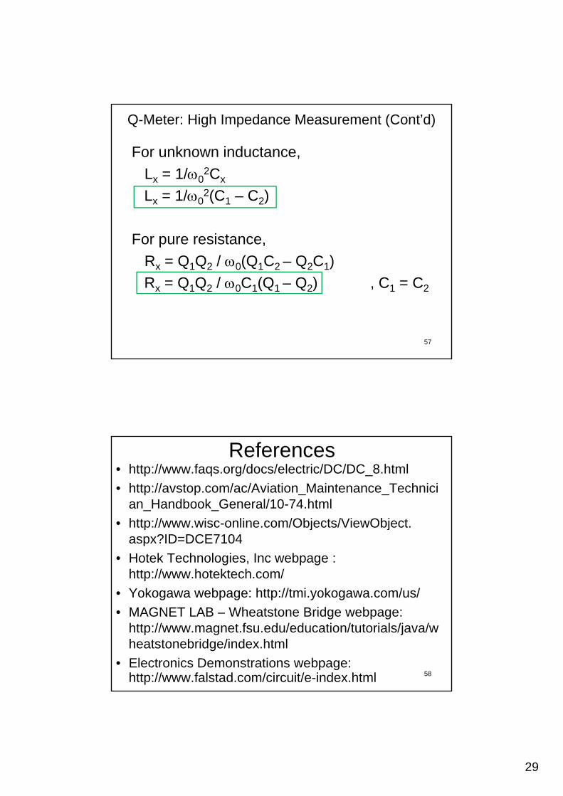
For unknown inductance,
Lx = 1/02Cx2
Q-Meter: High Impedance Measurement (Cont’d)
Lx = 1/02(C1 – C2)
For pure resistance,
Rx = Q1Q2 / 0(Q1C2 – Q2C1)
57
Rx = Q1Q2 / 0C1(Q1 – Q2) , C1 = C2
References• http://www.faqs.org/docs/electric/DC/DC_8.html
• http://avstop.com/ac/Aviation_Maintenance_Technician_Handbook_General/10-74.html
http://www wisc online com/Objects/ViewObject• http://www.wisc-online.com/Objects/ViewObject. aspx?ID=DCE7104
• Hotek Technologies, Inc webpage : http://www.hotektech.com/
• Yokogawa webpage: http://tmi.yokogawa.com/us/
• MAGNET LAB – Wheatstone Bridge webpage: http://www.magnet.fsu.edu/education/tutorials/java/wheatstonebridge/index.html
• Electronics Demonstrations webpage:http://www.falstad.com/circuit/e-index.html 58