Work, Energy and Powerwebstaff.kmutt.ac.th/~werapon.chi/ENE240/ENE240_2... · Single-Phase...
18
1 1 Work, Energy and Power • Work is an activity of force and movement in th di ti ff (J l ) the direction of force (Joules) • Energy is the capacity for doing work (Joules) • Power is the rate of using energy (Watt) P = W / t , Work done in the time E/t E t f di th ti 2 = E / t , Energy transferred in the time
Transcript of Work, Energy and Powerwebstaff.kmutt.ac.th/~werapon.chi/ENE240/ENE240_2... · Single-Phase...

1
1
Work, Energy and Power
• Work is an activity of force and movement in th di ti f f (J l )the direction of force (Joules)
• Energy is the capacity for doing work (Joules)
• Power is the rate of using energy (Watt)
P = W / t , Work done in the time E / t E t f d i th ti
2
= E / t , Energy transferred in the time
2
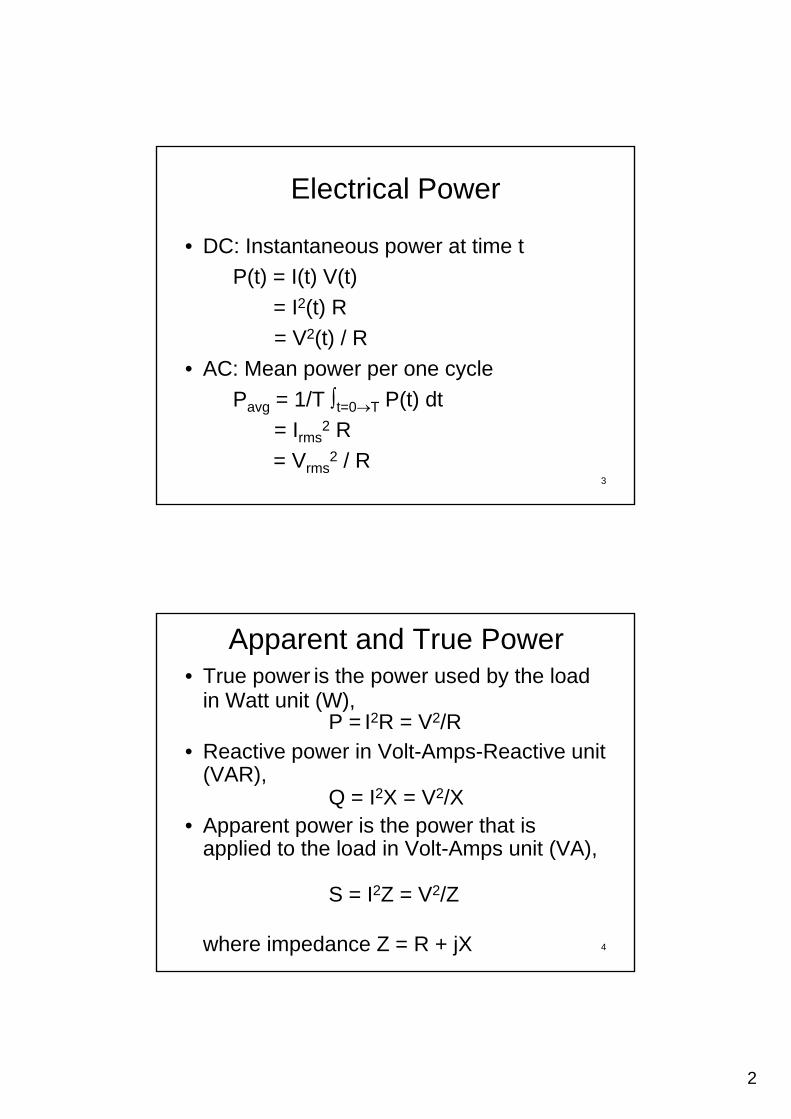
Electrical Power
• DC: Instantaneous power at time t
P(t) = I(t) V(t)
= I2(t) R
= V2(t) / R
• AC: Mean power per one cycle
3
Pavg = 1/T t=0T P(t) dt
= Irms2 R
= Vrms2 / R
Apparent and True Power• True power is the power used by the load
in Watt unit (W), P = I2R = V2/R
• Reactive power in Volt-Amps-Reactive unit (VAR),
Q = I2X = V2/X• Apparent power is the power that is
applied to the load in Volt-Amps unit (VA)
4
applied to the load in Volt Amps unit (VA),
S = I2Z = V2/Z
where impedance Z = R + jX

3
Power Factor
cos = True Power / Apparent Power
• Pure resistance, cos(0) = 1 perfect
• Pure inductance, cos(90) = 0
• Pure capacitance, cos(–90) = 0
Im
5
True Power
Reactive Power
Re
Im
0
Apparent Power
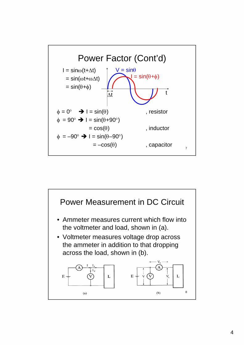
Power Factor (Cont’d)
P = I V cos
U t ki d f l d b i d• Up to a kind of loads being powered
• In phase or = 0 (resistor)
• Lagging or current lags voltage, > 0 (inductor)
• Leading or current leads voltage, < 0 (capacitor)
• Lower power factor (higher | | ), higher losses
6
p ( g | | ), g
• Need to improve power factor
4
Power Factor (Cont’d)I = sin(t+t)
= sin(t+t)
V = sinI = sin(+)
= sin(+)
= 0 I = sin() , resistor
= 90 I = sin(+90)
t t
7
= 90 I = sin(+90) = cos() , inductor
= –90 I = sin(–90) = –cos() , capacitor
Power Measurement in DC Circuit
• Ammeter measures current which flow into th lt t d l d h i ( )the voltmeter and load, shown in (a).
• Voltmeter measures voltage drop across the ammeter in addition to that dropping across the load, shown in (b).
8

5
Wattmeter
• To measure the true power
T fi d il i d tScale
P i t• Two fixed coil is used to provide a magnetic field that is proportional to a current passing through it, instead of using a permanent magnet
Spring
Pointer
Fixed Coil
Moving Coil(Rotatable)
I1I2
9
permanent magnet.
IB
Right Hand’s RuleElectrodynamometeras an ammeter (I2)
(Rotatable)
Meter Terminal
Wattmeter (Cont’d)
• Fixed coils, B I1• Moving coil, Torgue B I2Moving coil, Torgue B I2
= K I1 I2= K I2 , I = I1 = I2 I2 ammeter (non-linear scale)
10
Fixed Fixed
to AC sourceto load circuit

6
Wattmeter (Cont’d)
• Full-scale deflection current 5-100 mA
• For larger FSD up to 20 A, it is shunted by a low resistance.
• Electrodynamometer can be used for both DC and AC (rms) measurement.
11
Fixed Fixed
Shunt
Wattmeter (Cont’d)
• Electrodynamometer as a voltmeter V2 V
Fixed Fixed
to AC sourceto load circuit
12

7
Wattmeter (Cont’d)• Electrodynamometer as a wattmeter
IV • Loading error!• Loading error!
Fixed Fixed
to AC source to load circuit
13
Fixed Fixed
to AC source to load circuit
Wattmeter (Cont’d)
• Electrodynamometer
Index Needle
Fixed Coli
Spiral SpringIndex Needle
14
Moving Coli

8
Advantages• Used on AC as well as DC measurements
• Free from eddy current and hysteresis error (the difference in two measurements of the(the difference in two measurements of the same quantity when the measurement is approached from opposite directions)
• Accurate measurement of RMS values of voltages irrespective of waveforms.
• Because of precision grade accuracy and same calibration for AC and DC measurements, it is useful as transfer type and calibration instruments. 15
Disadvantages
• As the instrument has square law response, the scale is non-uniform.
• These instruments have small torque/weight ratio, so the frictional error is considerable.
• More costly than PMMC instruments.
• Adequate screening of the movements against stray magnetic fields is essential.
• Power consumption is comparably high because of their construction.
16
9
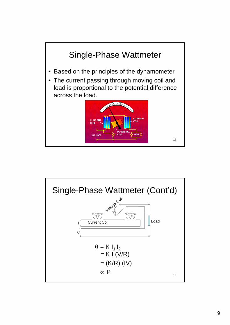
Single-Phase Wattmeter
• Based on the principles of the dynamometer
• The current passing through moving coil and load is proportional to the potential difference across the load.
17
Single-Phase Wattmeter (Cont’d)
= K I1 I2
I
V
LoadCurrent Coil
18
= K I1 I2= K I (V/R)
= (K/R) (IV)
P

10
• Low-current high-voltage load
Single-Phase Wattmeter (Cont’d)
Preading = Iload2(Rfixed+Rload)
Pload = Iload2Rload
Fixed
Supply Load
Iload
• High-current low-voltage loadP V 2 / (R || R )
Wattmeter reads high due to the potential drop across the fixed coil (if neglect the reactance).
MovingSupply Load
Fixed
19
Preading = Vload2 / (Rmoving || Rload)
= Vload2 (Rmoving+Rload)
RmovingRload
Pload = Vload2 / Rload
Wattmeter reads high due to the current through the movable coil (if neglect the reactance).
MovingSupply LoadVload
–
+
• Compensated wattmeter
Single-Phase Wattmeter (Cont’d)
To reduce the systematic error, the compensating
Compensating
Fixed
Supply LoadMoving
20
y , p gcoil current is, however, in the opposite direction to the load current and cancels out the proportion of the magnetic flux due to the moving coil current (the same number of turns).
11
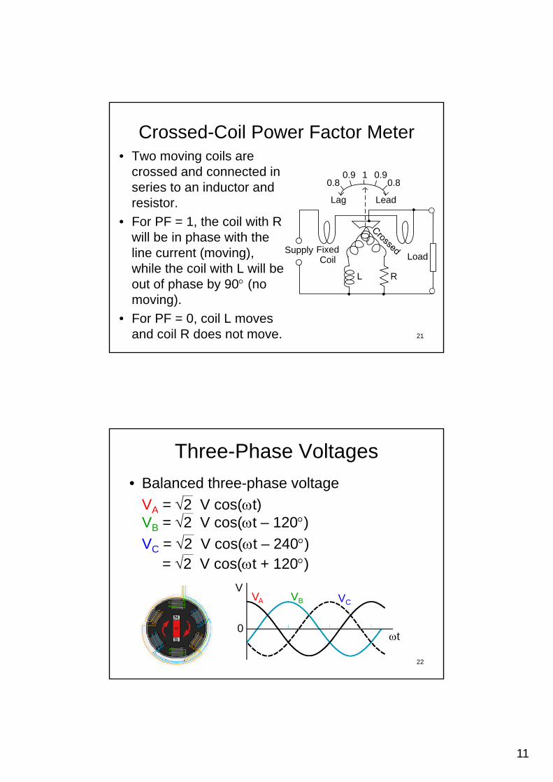
Crossed-Coil Power Factor Meter• Two moving coils are
crossed and connected in series to an inductor and
1 0.90.90.80.8series to an inductor and
resistor.
• For PF = 1, the coil with R will be in phase with the line current (moving), while the coil with L will be
FixedCoil Load
Lag Lead
0.80.8
Supply
21
while the coil with L will be out of phase by 90 (no moving).
• For PF = 0, coil L moves and coil R does not move.
L R
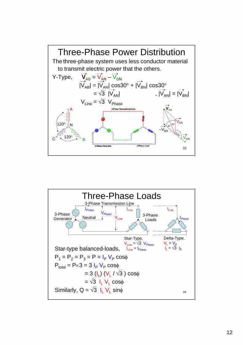
Three-Phase Voltages
• Balanced three-phase voltage
VA = 2 V cos(t) A ( )VB = 2 V cos(t – 120) VC = 2 V cos(t – 240)
= 2 V cos(t + 120)
V V VV
22
VA VB VC
0t
12
Three-Phase Power DistributionThe three-phase system uses less conductor material
to transmit electric power that the others.
Y-Type, VAB = VAN – VBN
|VAB| = |VAN| cos30 + |VBN| cos30= 3 |VAN| , |VAN| = |VBN|
VLine = 3 VPhase
A VAB
23
N120
120BC
3030
VAN
VBN
–VBN
Three-Phase Loads
3-Phase Generator
3-Phase Transmission Line
3-Phase Loads
ILine
Neutral IPhase
ILineVPhase
VLine
IPhase
Star-type balanced-loads,
P1 = P2 = P3 = P = IP VP cos
Star-Type,VLine = 3 VPhase
ILine = IPhase
Delta-Type,VL = VP
IL = 3 IP
24
Ptotal = P3 = 3 IP VP cos= 3 (IL) (VL / 3 ) cos= 3 IL VL cos
Similarly, Q = 3 IL VL sin

13
Three-Phase Wattmeter• For three-phase system with balanced
load, just using single-phase wattmeter, P3
Voltage Coil
Current Coil
R di
25
ReadingP = 3 /3 ILVLcos
Unbalanced-Load 3-Phase Wattmeter
P1
Using 3 Meters
P2
P3
26
P3
By using 3 wattmeters,
Ptotal = P1 + P2 + P3

14
Balanced-Load 3-Phase WattmeterBrondel’s theory,P = I1V1 + I2V2 + I3V3
P1
Kirchoff’s law,V1 = V3 + V1V2 = V3 + V2
1
P2
S
I1
I2I3
V1
V2
V3
Common
V1
0
27
Therefore,P = (I1+I2+I3)V3
+ I1V1 + I2V2= P1 + P2
I3V20
Balanced-Load 3-Phase Wattmeter (Cont’d)
By using 2 wattmeters,
P1 = IR VRB cos1
P1R
IR
VRB = VRS – VBS
Balanced, |VRS| = |VBS|
lagging
P2
B
Y
S
Using 2 Meters
28
VBS
–VBS
VRS
VRB
120IR
lagging
60 301 = 30 –
1

15
Balanced-Load 3-Phase Wattmeter (Cont’d)
P1 = ILVLcos(30 – )= ILVL ( 3 /2 cos + 1/2 sin )
Similarly, P2 = ILVL ( 3 /2 cos – 1/2 sin )
VBS
V
120
30
2 = 30 +
29Note: cos( ) = cos cos sin sin
–VBSVYS
VYB
IY
Balanced-Load 3-Phase Wattmeter (Cont’d)
Total Power,
Pt t l = P1 + P2Ptotal P1 + P2
= 3 ILVL cos
The same as using 1 meter for balanced load system
30
load system
and P1 – P2 = ILVL sin

16
Balanced-Load 3-Phase Wattmeter (Cont’d)
Reactive Power,
Q = 3 ILVL sin = 3 (P1 – P2)
(P1–P2)/(P1+P2) = ILVLsin / 3 ILVLcos= tan / 3
tan = 3 (P1 – P2) / (P1 + P2)
31
Balanced-Load 3-Phase Wattmeter (Cont’d)
sin2 + cos2 = 1
tan2 + 1 = 1/cos23(P P )2/(P +P )2 + 1 = 1/cos23(P1–P2)2/(P1+P2)2 + 1 = 1/cos2
Power factor,
cos = 1 / [ 1 + 3(P1–P2)2/(P1+P2)2 ]
32
17
Watt-Hour-Meter• To measure the electrical energy supplied to
industrial and domestic consumers in Joules.
Meters for smaller services such as small• Meters for smaller services, such as small residential customers, can be connected directly in-line between source and customer.
• For larger loads, more than about 200 ampere of load, current transformers are used, so that the meter can be located other than in line with the service conductors.
• The meters fall into two basic categories, electromechanical and electronic.
33
Watt-Hour-Meter (Cont’d)Electricity meters operate by continuously measuring
the instantaneous voltage and current to give energy used in Unit (kW-hr).
Generated Torque by Eddy Current = kg I V cosMagnetic Breaking Torque = kb N
where N is number of revolution per unit time
34
p
(gearing to a mechanical counter to count watt-hours)
kb N = kg I V cosN = (kg/kb) IVcos

18
Watt-Hour-Meter (Cont’d)
Voltage Coil
NGear Wheels for Dial Rotation
Rotating Aluminium Disk
Voltage Coil
Current Coil
S
S
NEddy Currrent
Magnetic break
35
Current Coil
Therefore, number of revolution refers to the energy used by loads.
References
• P. Purkait, B. Biswas, S. Das and C. K l “El t i l d El t iKoley, “Electrical and Electronics Measurements and Instrumentation”
• https://en.wikipedia.org/wiki/Electricity_meter#Types_of_meters
36