ENE 240 Class04 - KMUTTwebstaff.kmutt.ac.th/~werapon.chi/M2_3/1_2017/ENE_240_Class04.pdf ·...
16
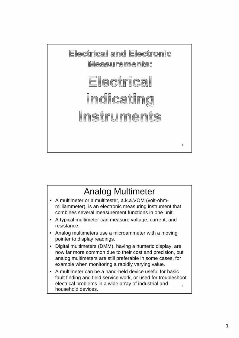
1 1 Analog Multimeter • A multimeter or a multitester, a.k.a.VOM (volt-ohm- milliammeter), is an electronic measuring instrument that combines several measurement functions in one unit. • A typical multimeter can measure voltage, current, and A typical multimeter can measure voltage, current, and resistance. • Analog multimeters use a microammeter with a moving pointer to display readings. • Digital multimeters (DMM), having a numeric display, are now far more common due to their cost and precision, but analog multimeters are still preferable in some cases for analog multimeters are still preferable in some cases, for example when monitoring a rapidly varying value. • A multimeter can be a hand-held device useful for basic fault finding and field service work, or used for troubleshoot electrical problems in a wide array of industrial and household devices. 2
Transcript of ENE 240 Class04 - KMUTTwebstaff.kmutt.ac.th/~werapon.chi/M2_3/1_2017/ENE_240_Class04.pdf ·...
1
1
Analog Multimeter• A multimeter or a multitester, a.k.a.VOM (volt-ohm-
milliammeter), is an electronic measuring instrument that combines several measurement functions in one unit.
• A typical multimeter can measure voltage, current, andA typical multimeter can measure voltage, current, and resistance.
• Analog multimeters use a microammeter with a moving pointer to display readings.
• Digital multimeters (DMM), having a numeric display, are now far more common due to their cost and precision, but analog multimeters are still preferable in some cases foranalog multimeters are still preferable in some cases, for example when monitoring a rapidly varying value.
• A multimeter can be a hand-held device useful for basic fault finding and field service work, or used for troubleshoot electrical problems in a wide array of industrial and household devices.
2
2
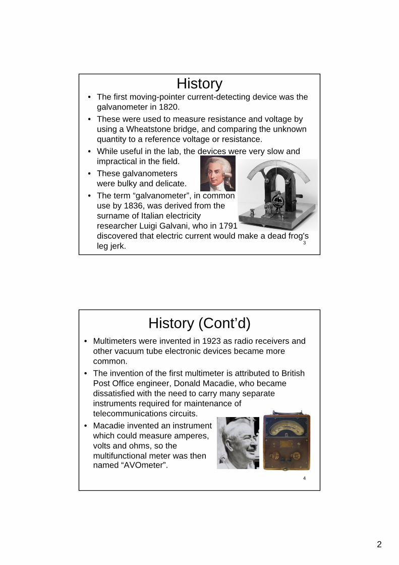
History• The first moving-pointer current-detecting device was the
galvanometer in 1820.
• These were used to measure resistance and voltage by using a Wheatstone bridge, and comparing the unknown quantity to a reference voltage or resistance.
• While useful in the lab, the devices were very slow and impractical in the field.
• These galvanometers were bulky and delicate.
• The term “galvanometer” in common• The term galvanometer , in common use by 1836, was derived from the surname of Italian electricity researcher Luigi Galvani, who in 1791 discovered that electric current would make a dead frog's leg jerk. 3
History (Cont’d)• Multimeters were invented in 1923 as radio receivers and
other vacuum tube electronic devices became more common.
• The invention of the first multimeter is attributed to British Post Office engineer, Donald Macadie, who became dissatisfied with the need to carry many separate instruments required for maintenance of telecommunications circuits.
• Macadie invented an instrument which could measure amperes, volts and ohms, so the multifunctional meter was then named “AVOmeter”.
4

3
History (Cont’d)• The Automatic Coil Winder and Electrical Equipment
Company (ACWEECO), founded in 1923, was set up to manufacture the Avometer and a coil winding machine also designed and patented by MacAdiedesigned and patented by MacAdie.
• Although a shareholder of ACWEECO, Macadie continued to work for the Post Office until his retirement in 1933.
• His son, Hugh S. Macadie, joined ACWEECO in 1927 and became Technical Director.
• The first AVO was put on sale in 1923,The first AVO was put on sale in 1923, and many of its features remained almost unaltered through to the last Model 8 Mark VII.
5
Analogue Meter’s Concept• Han Oersted, in 1820, noted his finding
without any explanation.y p
• Lord Kelvin made more sensitivity to a current.
I
+
–N
S
N
S
BB
Compass
6
y
Right-hand Rule
“Magnetic Field for Line of Current
by Biot Savart's Law”

4
Direct Current Meters• Moving Coil Galvanometer
http://youtu.be/_sD_5iyHl3s
• Permanent-Magnet Moving-Coil (PMMC)developed in 1881
7
CoilPointer
Permanent Magnet
• A lightweight coil of copper wire is attached to a shaft that pivots on two jewel bearing.
• The coil can rotate in a space between a cylindrical soft-iron core and two permanent magnetic pole pieces.
• The rotation is opposed by two fine hairsprings.
• The spring material must be nonmagnetic to avoid any magnetic field influence on the controlling force. Since the springs are also used to make electrical connection to the coil, th t h l i tthey must have a low resistance. Phosphor bronze is the material usually employed.
Deflecting Force = Controlling Force 8

5
• Jacques D’Arsonval’s Movement
When a current is passed through the coil it rotates, the angle through which it rotates being proportional to the current (0.0000001 – 1 A).
The magnetic field is designed (magneticThe magnetic field is designed (magnetic pole piece’s shape) that it is always at the right angles to the coil sides no matter what angle the coil has rotated through.
9Jacques-Arsène d'Arsonval(June 8, 1851 – December 31, 1940)A French physician and physicist
• Electric Current
B
B
FF
I
IL
b
• Fleming’s Left-Hand Rule
F = L I B
Force(Newton) Magnetic Field
Moving Coil
“Magnetic Force from a Straight Current-carrying Conductor”
10
(Newton) g(Tesla)
Current(Ampere)
Coil Side Length(Metre)
6
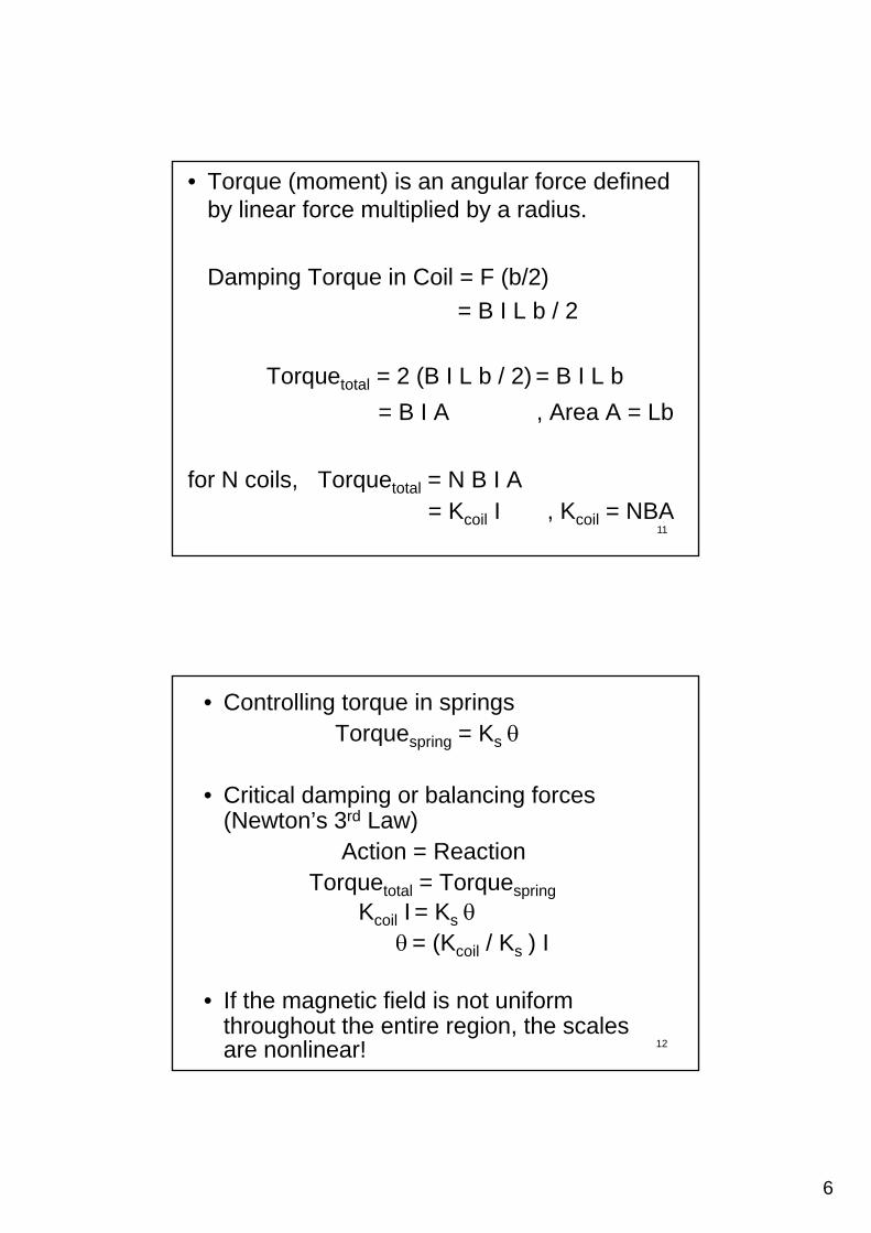
• Torque (moment) is an angular force defined by linear force multiplied by a radius.
Damping Torque in Coil = F (b/2)
= B I L b / 2
Torquetotal = 2 (B I L b / 2) = B I L b
= B I A , Area A = Lb
11
for N coils, Torquetotal = N B I A= Kcoil I , Kcoil = NBA
• Controlling torque in springsTorquespring = Ks
• Critical damping or balancing forces p g g(Newton’s 3rd Law)
Action = ReactionTorquetotal = Torquespring
Kcoil I = Ks= (K / K ) I
12
= (Kcoil / Ks) I
• If the magnetic field is not uniform throughout the entire region, the scales are nonlinear!

7
Galvanometer• Galvanometer with a zero at the center of
the scale used in DC instruments that can detect current flow in either directiondetect current flow in either direction
• Galvanometer with a zero at the left end of the scale indicates an upscale reading only for the proper way of connecting the meter into the circuit
13
Equivalent Ammeter Circuit
• The resistance of the meter coil and leads introduces a departure from the idealintroduces a departure from the ideal ammeter behavior. The model usually used to describe an ammeter in equivalent circuit is a resistance Rg in series with an ideal ammeter (no resistance)
14Ammeter
Rg 50 Ideal
Movement
8
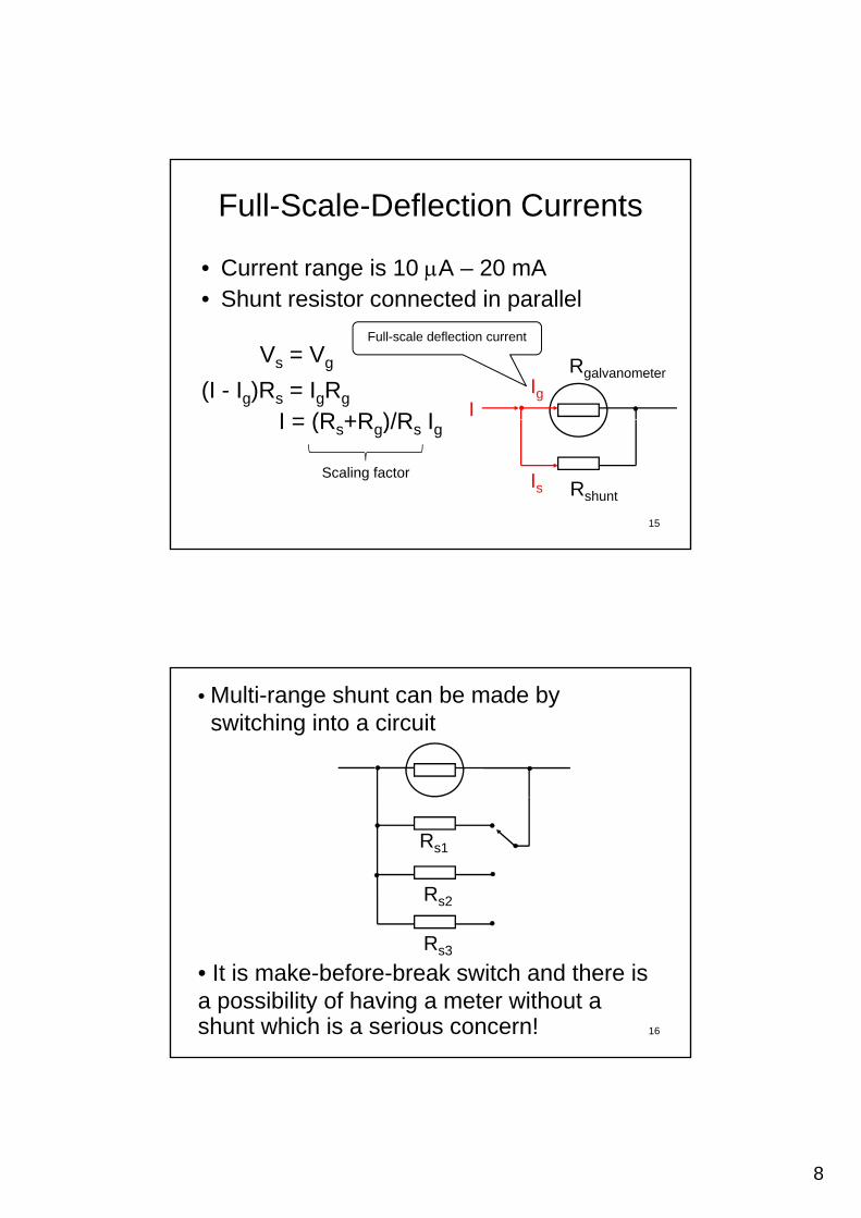
Full-Scale-Deflection Currents
• Current range is 10 A – 20 mA• Shunt resistor connected in parallel
Vs = Vg
(I - Ig)Rs = IgRg
I = (R +R )/R I
Rgalvanometer
IIg
Full-scale deflection current
15
I = (Rs+Rg)/Rs Ig
RshuntIs
Scaling factor
• Multi-range shunt can be made by switching into a circuit
Rs1
Rs2
16
Rs3
• It is make-before-break switch and there is a possibility of having a meter without a shunt which is a serious concern!
9
• Note:
In a switch where the contacts remain in one state unless actuated, such as a push-button switch the contacts can either bebutton switch, the contacts can either be normally open (NO) until closed by operation of the switch, or normally closed (NC) and opened by the switch action.
These may be "make-before-break" (shorting) which momentarily connects both circuits, or may be "break-before-make" (non-shorting) which interrupts one circuit before closing the other. 17
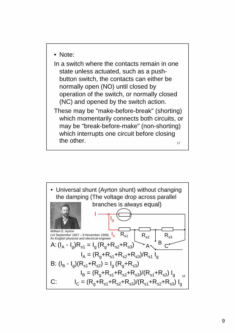
• Universal shunt (Ayrton shunt) without changing the damping (The voltage drop across parallel
branches is always equal)
II
A: (IA - Ig)Rs1 = Ig (Rg+Rs2+Rs3)
I = (R +R +R +R )/R I
Rs1 Rs2 Rs3
AB
C
Ig
IsWilliam E. Ayrton(14 September 1847 – 8 November 1908) An English physicist and electrical engineer
18
IA = (Rg+Rs1+Rs2+Rs3)/Rs1 IgB: (IB - Ig)(Rs1+Rs2) = Ig (Rg+Rs3)
IB = (Rg+Rs1+Rs2+Rs3)/(Rs1+Rs2) IgC: IC = (Rg+Rs1+Rs2+Rs3)/(Rs1+Rs2+Rs3) Ig

10
Note: Damping is an influence within an oscillatory system that has the effect of reducing, restricting or preventing its oscillations.
• Overdamped: the system returns (exponentially decays) to equilibrium without oscillatingoscillating.
• Critically damped: the system returns to equilibrium as quickly as possible without oscillating.
U d d d th• Underdamped: the system oscillates (at reduced frequency compared to the undamped case) with the amplitude gradually decreasing to zero.
• Undamped: the system oscillates at its natural resonant frequency.
19
e.g. RLC circuit
The ideal LC circuit forms an harmonic oscillator for current by the energy stored in two different ways: in an electric field as the capacitor is charged and in a magnetic field as current flows through the inductor.
The resonance frequency is defined as the frequency at whichThe resonance frequency is defined as the frequency at which the impedance of the circuit is at a minimum (impedance is purely real or purely resistive).
Introducing the resistor increases the decay of these oscillations with time to zero which is also known asto zero, which is also known as damping (some resistance is unavoidable in real circuits even if a resistor is not specifically included as a component).
Damping determines whether or not the circuit will resonate naturally (that is, without a driving source). 20
11
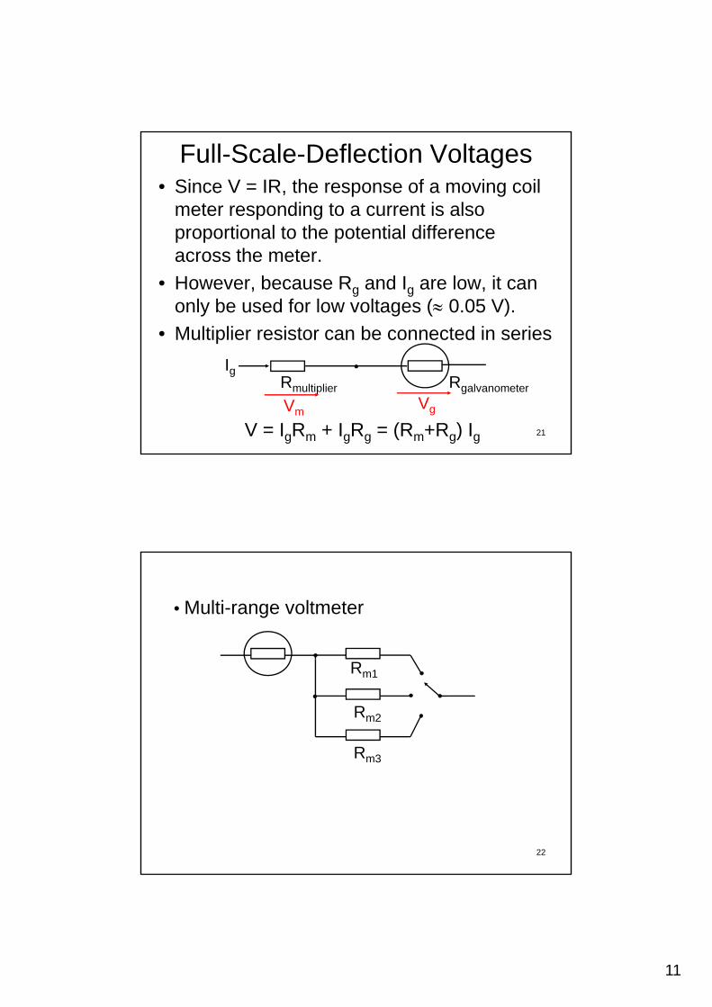
Full-Scale-Deflection Voltages• Since V = IR, the response of a moving coil
meter responding to a current is also proportional to the potential difference p p pacross the meter.
• However, because Rg and Ig are low, it can only be used for low voltages ( 0.05 V).
• Multiplier resistor can be connected in series
21V = IgRm + IgRg = (Rm+Rg) Ig
Rmultiplier Rgalvanometer
Ig
VmVg
• Multi-range voltmeter
Rm1
Rm2
Rm3
22
12
Rm1 Rm2 Rm3
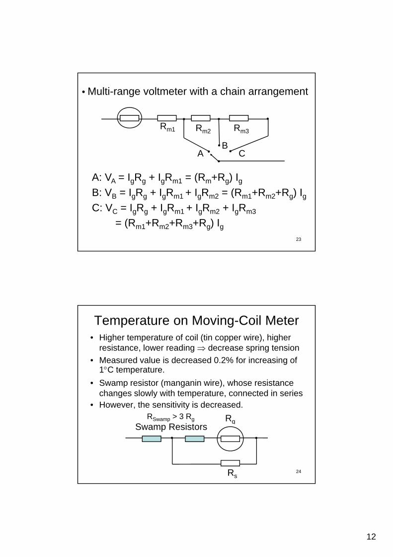
• Multi-range voltmeter with a chain arrangement
m2 m3
AB
C
A: VA = IgRg + IgRm1 = (Rm+Rg) IgB: V = I R + I R + I R = (R +R +R ) I
23
B: VB = IgRg + IgRm1 + IgRm2 = (Rm1+Rm2+Rg) IgC: VC = IgRg + IgRm1 + IgRm2 + IgRm3
= (Rm1+Rm2+Rm3+Rg) Ig
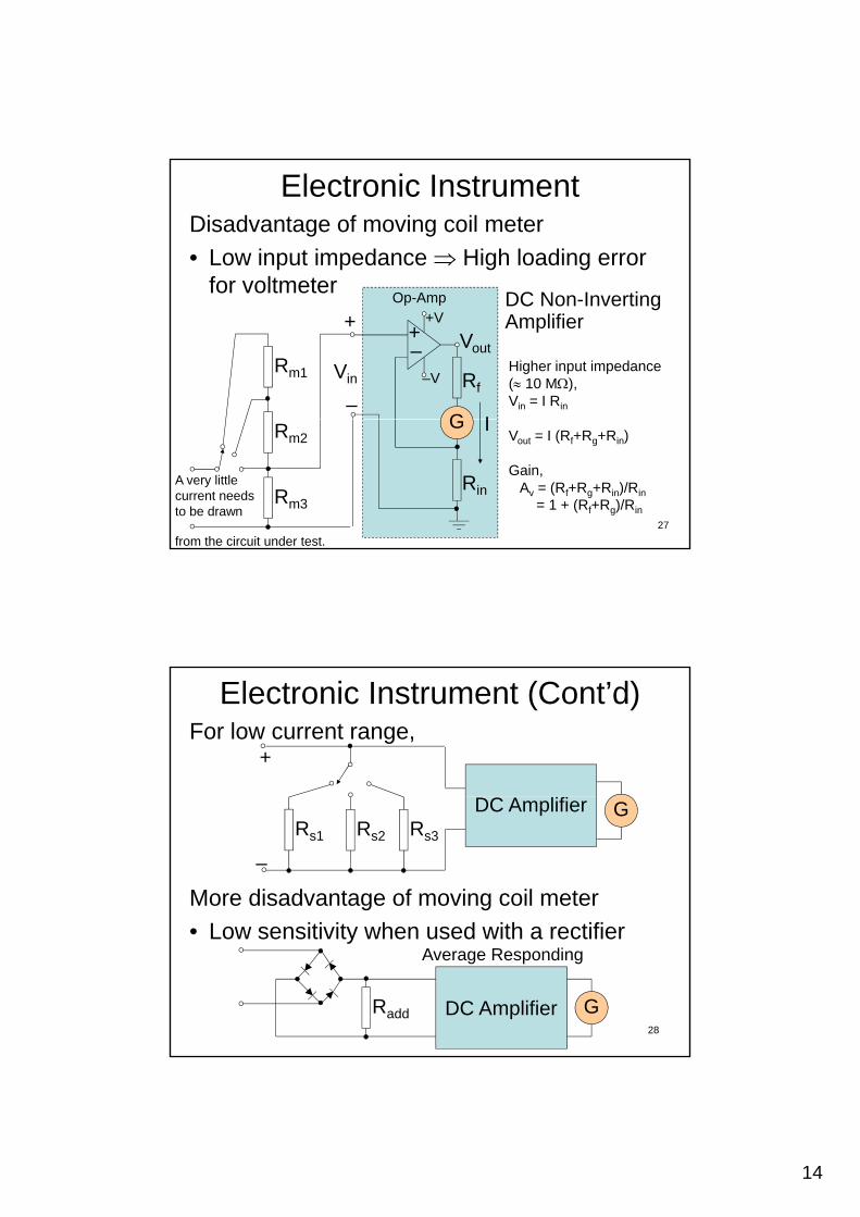
Temperature on Moving-Coil Meter• Higher temperature of coil (tin copper wire), higher
resistance, lower reading decrease spring tension
• Measured value is decreased 0.2% for increasing of g1C temperature.
• Swamp resistor (manganin wire), whose resistance changes slowly with temperature, connected in series
• However, the sensitivity is decreased.
RgS R i t
RSwamp > 3 Rg
24Rs
Swamp Resistors

13
Sensitivity on Moving-Coil Meter
• Sensitivity = Pointer Change / Input Change
S = / I
or S = 1 / Ifsd
= R / Vfsd
25
Ammeter & Voltmeter Loading
• Systematic loading error C l l ti b i Thé i ’ th i Calculation by using Thévenin’s theorem in
Lecture 2
26
14
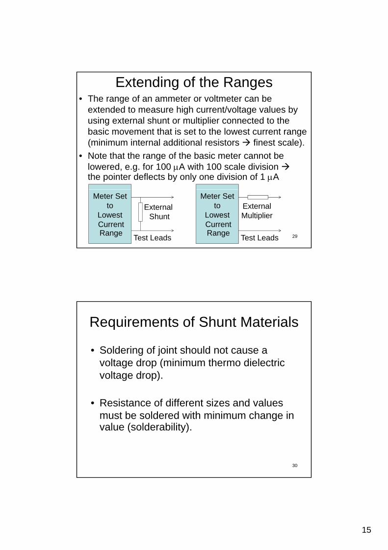
Electronic InstrumentDisadvantage of moving coil meter
• Low input impedance High loading error for voltmeterfor voltmeter
–
Rm1 Rf
G
+–
Op-Amp
–V
+V
Vin
+Vout
I
DC Non-Inverting Amplifier
Higher input impedance ( 10 M),Vin = I Rin
27
Rm3
Rm2G
Rin
IVout = I (Rf+Rg+Rin)
Gain,Av = (Rf+Rg+Rin)/Rin
= 1 + (Rf+Rg)/Rin
A very little current needs to be drawn
from the circuit under test.
Electronic Instrument (Cont’d)For low current range,
+
More disadvantage of moving coil meter
L iti it h d ith tifi
–
Rs2Rs1 Rs3
DC Amplifier G
28
• Low sensitivity when used with a rectifier
Radd DC Amplifier G
Average Responding
15
Extending of the Ranges• The range of an ammeter or voltmeter can be
extended to measure high current/voltage values by using external shunt or multiplier connected to the basic movement that is set to the lowest current rangebasic movement that is set to the lowest current range (minimum internal additional resistors finest scale).
• Note that the range of the basic meter cannot be lowered, e.g. for 100 A with 100 scale division the pointer deflects by only one division of 1 A
29
External Shunt
Test Leads
Meter Set to
Lowest CurrentRange
External Multiplier
Test Leads
Meter Set to
Lowest CurrentRange
Requirements of Shunt Materials
• Soldering of joint should not cause a lt d ( i i th di l t ivoltage drop (minimum thermo dielectric
voltage drop).
• Resistance of different sizes and values must be soldered with minimum change inmust be soldered with minimum change in value (solderability).
30
16
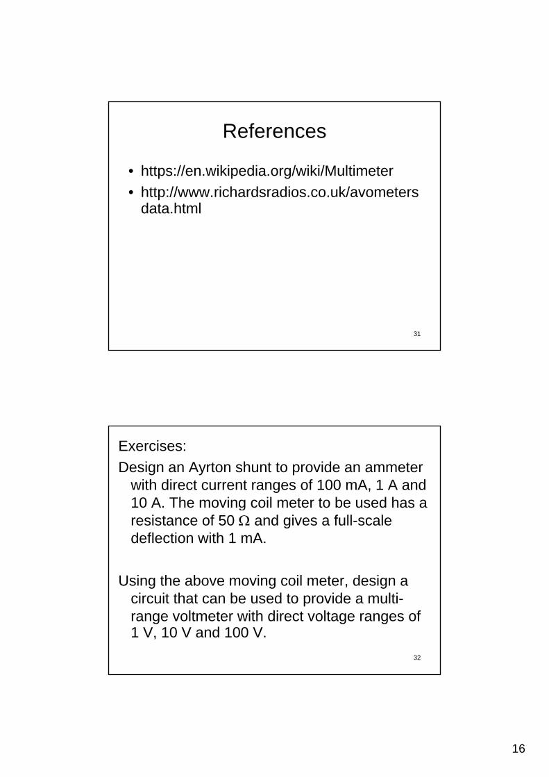
References
• https://en.wikipedia.org/wiki/Multimeter
• http://www.richardsradios.co.uk/avometersdata.html
31
Exercises:
Design an Ayrton shunt to provide an ammeter with direct current ranges of 100 mA, 1 A and 10 A. The moving coil meter to be used has a gresistance of 50 and gives a full-scale deflection with 1 mA.
Using the above moving coil meter, design a circuit that can be used to provide a multi-range voltmeter with direct voltage ranges of 1 V, 10 V and 100 V.
32