Encoder programming with EPROGeng/electronics/legacy/steve_magee/encoders/TR... · Encoder...
49
Encoder programming with EPROG Enclosed Disk Art.-No.: 490-00404 Operating manual for parameterizing software Please keep for further use ! Edition-/Rev.-Date: 10.06.1998 Document-/Rev.-No.: TR - E - BA - GB - 0011 - 04 Soft edition: see Disk File name: TR-E-BA-GB-0011.DOC Author: MAH/MÜJ TR - Electronic GmbH Eglishalde 6 D-78647 Trossingen Telephone ++49 (0)7425 / 228-0 Telefax ++49 (0)7425 / 228-33
-
Upload
hoangxuyen -
Category
Documents
-
view
226 -
download
1
Transcript of Encoder programming with EPROGeng/electronics/legacy/steve_magee/encoders/TR... · Encoder...

Encoder programmingwith EPROG
Enclosed DiskArt.-No.: 490-00404
Operating manualfor parameterizing software
Please keep for further use !
Edition-/Rev.-Date: 10.06.1998Document-/Rev.-No.: TR - E - BA - GB - 0011 - 04Soft edition: see DiskFile name: TR-E-BA-GB-0011.DOCAuthor: MAH/MÜJ
TR - Electronic GmbHEglishalde 6D-78647 Trossingen
Telephone ++49 (0)7425 / 228-0Telefax ++49 (0)7425 / 228-33

Operating manual ELECTRONIC GmbH
TR - ELECTRONIC GmbH, Global Quality Management, Eglishalde 6, 78647 Trossingen, Tel. ++49 (0)7425-228-0, Fax ++49 (0)7425-228-33
Date: 10.06.1998 TR - E - BA - GB - 0011 - 04 Page 2 of 49
Imprint
TR-Electronic GmbHD-78647 TrossingenEglishalde 6Tel.: (0049) 07425/228-0Fax: (0049) 07425/228-33
Copyright 1997 TR-Electronic
Guarantee
In our ongoing efforts to improve our products, TR-Electronic reserve the right to alterthe information contained in this document without prior notice.
Printing
This manual was edited using text formatting software on a DOS personal computer.The text was printed in Arial.
Fonts
Italics and bold type are used for the title of a document or to emphasize textpassages.
Passages written in Courier show text which is visible on the screen / display as wellas software menu selections.
"< >" refers to keys on your computer keyboard (e.g. <RETURN>).
NoteText following the "NOTE" symbol describes important features of the respectiveproduct.
Copyright Information ©
MS-DOS is a registered trademark of Microsoft Corporation.
COM-ET-200 is a registered trademark of SIEMENS Corporation.

Operating manual ELECTRONIC GmbH
TR - ELECTRONIC GmbH, Global Quality Management, Eglishalde 6, 78647 Trossingen, Tel. ++49 (0)7425-228-0, Fax ++49 (0)7425-228-33
Date: 10.06.1998 TR - E - BA - GB - 0011 - 04 Page 3 of 49
Revision History
Note:The cover of this document shows the current revision status and the correspondingdate. Since each individual page has its own revision status and date in the footer,there may be different revision statuses within the document.
Document created: 29.01.1996
Revision Date
Document inserted: "Operating Manual For ConfigurationSoftware" (TR-ECE-BA-D-006).
10.06.1998
i
Operating manual ELECTRONIC GmbH
TR - ELECTRONIC GmbH, Global Quality Management, Eglishalde 6, 78647 Trossingen, Tel. ++49 (0)7425-228-0, Fax ++49 (0)7425-228-33
Date: 10.06.1998 TR - E - BA - GB - 0011 - 04 Page 4 of 49
Table of contents
1 Instructions for configuration and commissioning ............................................................... 7
1.1 Safety Information ...................................................................................................... 7
1.2 Instructions for configuration and installation............................................................... 7
1.3 Shielding..................................................................................................................... 8
1.4 Configuring instructions............................................................................................... 8
1.5 Commissioning instructions......................................................................................... 9
2 Encoder concept...................................................................................................................... 10
3 Program EPROG ...................................................................................................................... 11
3.1 Dialog ......................................................................................................................... 113.1.1 Lines............................................................................................................ 113.1.2 Sections....................................................................................................... 123.1.3 Paging ......................................................................................................... 123.1.4 Saving ......................................................................................................... 14
3.2 Data Transmission ...................................................................................................... 143.2.1 Device access ............................................................................................. 143.2.2 File access .................................................................................................. 14
3.3 Status Display............................................................................................................. 15
3.4 Keyboard Commands ................................................................................................. 153.4.1 Paging ......................................................................................................... 153.4.2 Dialog line with selection list ........................................................................ 153.4.3 Dialog line with digit..................................................................................... 153.4.4 Digit or text entry ......................................................................................... 153.4.5 General ....................................................................................................... 163.4.6 Device access ............................................................................................. 163.4.7 File access .................................................................................................. 16
4 Cabling the unit........................................................................................................................ 17
4.1 Cabling for programming with EPROG........................................................................ 17
4.2 Cabling for position indication with TA resp. with TA-Mini............................................ 18
5 Programming with EPROG...................................................................................................... 19
5.1 Device section....................................................................................................... 19
5.2 Equipment section................................................................................................. 19
5.3 Axis name section................................................................................................. 20
5.4 Stroke section....................................................................................................... 205.4.1 Stroke, 1 rev. ............................................................................................ 205.4.2 Power of 2 stroke................................................................................. 215.4.3 Integer stroke ....................................................................................... 215.4.4 Fraction stroke ..................................................................................... 225.4.5 Counting direction........................................................................................ 225.4.6 Initial value .................................................................................................. 22
5.5 Preset inputs section ......................................................................................... 22
5.6 PT/TA section ......................................................................................................... 235.6.1.1 General restrictions for PT100 operation ...................................... 23
Operating manual ELECTRONIC GmbH
TR - ELECTRONIC GmbH, Global Quality Management, Eglishalde 6, 78647 Trossingen, Tel. ++49 (0)7425-228-0, Fax ++49 (0)7425-228-33
Date: 10.06.1998 TR - E - BA - GB - 0011 - 04 Page 5 of 49
5.6.1.2 Type specific restrictions for PT100 operation .............................. 24
5.7 Signal bits section.............................................................................................. 25
5.8 Cams section ............................................................................................................ 255.8.1 Stroke.......................................................................................................... 255.8.2 Advance times............................................................................................. 265.8.3 Displacement............................................................................................... 275.8.4 Tracks ......................................................................................................... 27
5.9 SSI section .............................................................................................................. 275.9.1 Interface ...................................................................................................... 275.9.2 Data and signal bits ..................................................................................... 285.9.3 Data bits ...................................................................................................... 285.9.4 Signal bits.................................................................................................... 29
5.9.4.1 Upward movement, downward movement .................................... 295.9.4.2 Previous upward movement ......................................................... 295.9.4.3 Ongoing movement...................................................................... 295.9.4.4 Static and dynamic error (watchdog)............................................. 295.9.4.5 Maximum speed........................................................................... 305.9.4.6 1st to 4th limit switch .................................................................... 305.9.4.7 Even parity, even error parity ....................................................... 30
5.10 ISI section ............................................................................................................ 31
5.11 Section Digital outputs ..................................................................................... 32
5.12 Parallel interface section............................................................................ 325.12.1 Interface .................................................................................................... 32
5.12.1.1 Inverting function........................................................................ 325.12.1.2 Bus function ............................................................................... 325.12.1.3 Latch function............................................................................. 335.12.1.4 Dynamic strobe .......................................................................... 335.12.1.5 20 strobe..................................................................................... 345.12.1.6 Continuous progressive codes .................................................... 34
5.12.2 Data and signal bits ................................................................................... 35
5.13 Profibus DP section............................................................................................ 355.13.1 Interface .................................................................................................... 355.13.2 Data and signal bits ................................................................................... 36
5.14 Section Analog outputs ....................................................................................... 375.14.1 Latch function ............................................................................................ 385.14.2 Inversion function ...................................................................................... 38
5.15 Actual values section ....................................................................................... 395.15.1 Position...................................................................................................... 395.15.2 Velocity...................................................................................................... 395.15.3 Errors......................................................................................................... 39
5.15.3.1 Components ............................................................................... 405.15.3.2 Central disk ................................................................................ 405.15.3.3 Satellite ...................................................................................... 405.15.3.4 FRAM checksum ........................................................................ 405.15.3.5 Cam speed................................................................................. 405.15.3.6 Warm restart .............................................................................. 415.15.3.7 Overspeed.................................................................................. 415.15.3.8 Analog outputs............................................................................ 41
5.15.4 Interfaces................................................................................................... 41

Operating manual ELECTRONIC GmbH
TR - ELECTRONIC GmbH, Global Quality Management, Eglishalde 6, 78647 Trossingen, Tel. ++49 (0)7425-228-0, Fax ++49 (0)7425-228-33
Date: 10.06.1998 TR - E - BA - GB - 0011 - 04 Page 6 of 49
6 Appendix .................................................................................................................................. 42
6.1 Dimensioned drawing, pin assignment, available options ............................................ 42
6.2 Technical data ............................................................................................................ 426.2.1 Power supply ............................................................................................... 42
6.2.1.1 CE65 SSI ..................................................................................... 426.2.1.2 CE65 SSI+parallel 32xUS level .................................................... 426.2.1.3 CE65 SSI+ISI............................................................................... 436.2.1.4 CE65 SSI+Profibus ...................................................................... 436.2.1.5 CE65 SSI+analog output .............................................................. 43
6.2.2 Times .......................................................................................................... 436.2.3 Clock frequency for SSI output .................................................................... 43
6.2.3.1 SSI clock frequency and monoflop time........................................ 436.2.3.2 SSI clock frequency and line lengths ............................................ 446.2.3.3 Optimum SSI clock pulse polarity ................................................. 44
6.2.4 Instructions for cabling................................................................................. 45
6.3 Accessories ................................................................................................................ 45
6.4 Glossary ..................................................................................................................... 466.4.1 Absolute encoder......................................................................................... 466.4.2 FRAM.......................................................................................................... 466.4.3 Incremental encoder .................................................................................... 466.4.4 ISI................................................................................................................ 476.4.5 Interface ...................................................................................................... 476.4.6 LA................................................................................................................ 476.4.7 LSPM2 ........................................................................................................ 476.4.8 Luenberg observer....................................................................................... 486.4.9 Parallel interface.......................................................................................... 486.4.10 Profibus DP ............................................................................................... 486.4.11 Rotating absolute encoder ......................................................................... 486.4.12 Satellite ..................................................................................................... 486.4.13 SSI ............................................................................................................ 49

Operating manual ELECTRONIC GmbH
TR - ELECTRONIC GmbH, Global Quality Management, Eglishalde 6, 78647 Trossingen, Tel. ++49 (0)7425-228-0, Fax ++49 (0)7425-228-33
Date: 10.06.1998 TR - E - BA - GB - 0011 - 04 Page 7 of 49
1 Instructions for configuration and commissioning
1.1 Safety Information
This operating manual contains information that you must comply with to ensure yourpersonal safety and to avoid damage to property. The information is emphasized bywarning triangles, which have different appearances to match the level of danger:
WarningMeans that if the appropriate safety measures are ignored, death, severe injury orconsiderable damage to property can occur.
CautionMeans that if the appropriate safety measures are ignored, slight injury or damage toproperty can occur.
Commissioning and operation of a unit may be carried out by qualified personnelonly. Qualified personnel in the sense of the safety instructions contained in thisoperating manual are persons who are authorized to commission, connect to groundand to mark units, systems and electric circuits according to the standards of safetytechnology.
1.2 Instructions for configuration and installation
In most cases, the product will be used as a component which is part of largersystems. For this reason, these instructions are meant to give guidelines for safeintegration of the product into its environment.
Warning
• The specific safety regulations and regulations for accident prevention must becomplied with.
• The EN (European Standards), VDE (Association of German Electricians) and DIN
standards applying to your plant must be complied with.

Operating manual ELECTRONIC GmbH
TR - ELECTRONIC GmbH, Global Quality Management, Eglishalde 6, 78647 Trossingen, Tel. ++49 (0)7425-228-0, Fax ++49 (0)7425-228-33
Date: 10.06.1998 TR - E - BA - GB - 0011 - 04 Page 8 of 49
1.3 Shielding
The use of electronic-sensor active systems in modern machines requires a conceptfor interference suppression and cabling which must be implemented correctly andconsistently.
A plant containing electronic measuring systems as well as the cassette may only runsmoothly if these requirements are met.
Recommendation for shield cabling
Switching Cabinet
Control Unit
Power Unit
MachineMeasuring Systems
Power Cable
Ground cable 10 mm²(R ground cable << R screen)
0V bar with screenterminal for measuringsystem cable
Measuring sys-tem and controlcable
1.4 Configuring instructions
• Route (screened) lines connecting to the encoder either a long way from orcompletely physically separated from energy lines that carry disturbances.
• Use only completely screened lines for data transfer and ensure they are well
earthed. In the case of differential data transfer, (RS422, RS485 etc.), you mustadditionally use twisted-pair lines.
• Use cables with a minimum cross-section of 0.22 mm² for data transfer.
• Use a ground cable with a minimum cross-section of 10 mm² to avoidequipotential bonding via the screen. In this context, you should ensure that theground cable's resistance must be much lower than the screen's resistance.
• Wire the screen continuously keeping a large area in contact with special screenconnecting terminals.
• Avoid crossing cables. If this is not possible, the cables should only cross at right-angles.

Operating manual ELECTRONIC GmbH
TR - ELECTRONIC GmbH, Global Quality Management, Eglishalde 6, 78647 Trossingen, Tel. ++49 (0)7425-228-0, Fax ++49 (0)7425-228-33
Date: 10.06.1998 TR - E - BA - GB - 0011 - 04 Page 9 of 49
1.5 Commissioning instructions • Cabling at the mating connector or in the control cabinet may be carried out in
dead condition only. • Before commissioning the plant, check all connections between the mating
connector and the control cabinet. • Plug in or unplug mating connectors of signal or supply lines in dead condition
only. • Do not make mechanical or electrical modifications to the axis cassette or the
measuring systems. • Carry out commissioning according to the safety instructions.

Operating manual ELECTRONIC GmbH
TR - ELECTRONIC GmbH, Global Quality Management, Eglishalde 6, 78647 Trossingen, Tel. ++49 (0)7425-228-0, Fax ++49 (0)7425-228-33
Date: 10.06.1998 TR - E - BA - GB - 0011 - 04 Page 10 of 49
2 Encoder concept
CE means Compact Encoder. It is a programmable absolute optoelectronic path-measuring system.
The rotating measuring shaft of the absolute encoder carries a disc on which circulartracks with transparent and non-transparent fields are to be found. There can besatellite discs for measuring the rotations connected with the central disc by areducing gear. The code discs are scanned by light barriers and thus their position isconverted into digital electric signals.
Absolute means that the position data provided by the absolute encoder indicate theposition of the measuring shaft immediately and without further notice. Different fromthis, an incremental encoder transmits pulses when positions change which must becollected in a counter by the user. The disadvantage is that a home position must bedriven to when starting the machine where the counter is reset to zero. Moreover,disturbing pulses are permanently stored in the counter, which is why home returnmust be repeated frequently.
The light barrier signals are processed by a microprocessor. It serves for adjustingzero point, resolution and measuring range. Moreover, it provides additionalfunctions such as self-regulation, standstill and rotational direction recognition,overspeed monitor, limit switch and dynamic camshaft gear.
The encoder can provide the following interfaces for transmitting output data to theuser: SSI, ISI, parallel using up to 32 outputs, Profibus and switching outputs for theadditional functions.
With moving encoder, the output data lag behind the position. This is mainly causedby the processing time or cycle time of the microprocessor program in the encoder.The cycle time depends on the selected interfaces and options. Some typical cycletimes are listed for orientation in a table in the appendix (see chapter 6.2.2 Times).
As the cycle of the encoder is not synchronized with the data transfer to theconnected control system, the ages of the transferred output data fluctuate irregularlybetween single and double cycle period. This does generally not lead to problems, asthis cycle period is normally considerably shorter than the cycle of the connectedcontrol system. For the rarely occurring cases of the synchronization being necessaryfor very fast control, there are special types available.
Programming the encoder is executed serially via a bifilar RS485 interface, whichallows high immunity to interfering and cable lengths up to 1,000 m. As operatordevice and for filing data, an IBM-compatible PC with the program EPROG is used. Itis connected to the encoder via one of its V24 interfaces with a so-called PC adapter.The latter contains a potential segregation and the conversion from V24 to RS485.
The encoder can optionally be programmed or adjusted with the handy terminalPT100 if it has been prepared to it by EPROG. In this case, however, some adjustingoptions are not available, and for filing the programs, EPROG must be used again. Aposition indicator can be connected instead of the PT100. The slave indicator TA has8 decades, the slave indicator TAMINI 6 decades. If a negative sign must bedisplayed, one decade is dropped.

Operating manual ELECTRONIC GmbH
TR - ELECTRONIC GmbH, Global Quality Management, Eglishalde 6, 78647 Trossingen, Tel. ++49 (0)7425-228-0, Fax ++49 (0)7425-228-33
Date: 10.06.1998 TR - E - BA - GB - 0011 - 04 Page 11 of 49
3 Program EPROG
EPROG is a PC program for serial programming of position measuring devices. AnIBM-compatible PC is required. The processor must be at least a 10 MHz 8088processor or a 6 MHz 8086 processor and the operating system must be MS-DOS 3.0or above. The program also runs in the DOS box of Windows 3.1 or higher, thenhowever at least a 486DX2/66 processor must be used.Data interchange between the PC and the measuring device is via one of the serialV.24 interfaces at 115 kbps. It is necessary to plug on the PC adapter which isresponsible for electrical isolation and converting the signal to RS485 whereby therange is expanded to up to 800 m.
3.1 Dialog
The dialog is primarily used for viewing and changing the programming of theconnected device. It is shown on the left of the EPROG window.
3.1.1 Lines
The dialog consists of lines which are shown one below the other. There is one linefor each value to be displayed. On the left-hand side, the designation of the value isgiven and on the right-hand side the value itself, for example Steps per rev. and4096.There are five different types of dialog lines:
1.) Title lines which do not have a value and whose designation is only used as atitle, for example for a section.
2.) Lines for integer values from -231 to +231-13.) Lines for floating point values in IEEE format with 64 bits.4.) Lines for text values5.) Lines for selection lists. The selection list consists of several predefined texts,
for example Yes and No. One of these is shown as a value or as selected.
Some of the dialog lines are only used to display actual values such as velocity orspeed or a bit pattern which is to be written to an interface. They cannot be changed.
Dialog lines that are not needed become invisible. If an interface that is not needed isdisconnected, for example, the associated subordinate dialog lines disappear until theinterface is connected again. The main application is switching between standardand extended options which usually appears in the first line. It deactivates lineswith settings that are rarely needed and assigns standard values to them.
Operating manual ELECTRONIC GmbH
TR - ELECTRONIC GmbH, Global Quality Management, Eglishalde 6, 78647 Trossingen, Tel. ++49 (0)7425-228-0, Fax ++49 (0)7425-228-33
Date: 10.06.1998 TR - E - BA - GB - 0011 - 04 Page 12 of 49
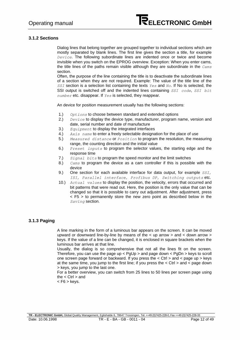
3.1.2 Sections
Dialog lines that belong together are grouped together to individual sections which aremostly separated by blank lines. The first line gives the section a title, for exampleDevice. The following subordinate lines are indented once or twice and becomeinvisible when you switch on the EPROG overview. Exception: When you enter cams,the title lines of the paths remain visible although they are subordinate in the Camssection.Often, the purpose of the line containing the title is to deactivate the subordinate linesof a section when they are not required. Example: The value of the title line of theSSI section is a selection list containing the texts Yes and No. If No is selected, theSSI output is switched off and the indented lines containing SSI code, SSI bitnumber etc. disappear. If Yes is selected, they reappear.
An device for position measurement usually has the following sections:
1.) Options to choose between standard and extended options2.) Device to display the device type, manufacturer, program name, version and
date, serial number and date of manufacture3.) Equipment to display the integrated interfaces4.) Axis name to enter a freely selectable designation for the place of use5.) Measured distance or Position to program the resolution, the measuring
range, the counting direction and the initial value6.) Preset inputs to program the selector values, the starting edge and the
response time7.) Signal bits to program the speed monitor and the limit switches8.) Cams to program the device as a cam controller if this is possible with the
device9.) One section for each available interface for data output, for example SSI,
ISI, Parallel interface, Profibus DP, Switching outputs etc.10.) Actual values to display the position, the velocity, errors that occurred and
bit patterns that were read out. Here, the position is the only value that can bechanged so that it is possible to carry out adjustment. After adjustment, press< F5 > to permanently store the new zero point as described below in theSaving section.
3.1.3 Paging
A line marking in the form of a luminous bar appears on the screen. It can be movedupward or downward line-by-line by means of the < up arrow > and < down arrow >keys. If the value of a line can be changed, it is enclosed in square brackets when theluminous bar arrives at that line.Usually, the dialog is so comprehensive that not all the lines fit on the screen.Therefore, you can use the page up < PgUp > and page down < PgDn > keys to scrollone screen page forward or backward. If you press the < Ctrl > and < page up > keysat the same time, you jump to the first line; if you press the < Ctrl > and < page down> keys, you jump to the last one.For a better overview, you can switch from 25 lines to 50 lines per screen page usingthe < Ctrl > and< F6 > keys.

Operating manual ELECTRONIC GmbH
TR - ELECTRONIC GmbH, Global Quality Management, Eglishalde 6, 78647 Trossingen, Tel. ++49 (0)7425-228-0, Fax ++49 (0)7425-228-33
Date: 10.06.1998 TR - E - BA - GB - 0011 - 04 Page 13 of 49
The < F2 > key switches on the overview, that means all the indented andsubordinate lines disappear so that only the first lines of the sections are visible. Nowyou can quickly move the luminous bar to the beginnning of the desired section andthen press < F2 > to switch back to the complete view.
Entry
To change the value of a line, you must first mark the line by means of the luminousbar. The entry is carried out in different ways depending on the type of the value andis terminated by pressing the< Return > key or paging to a new line. If the device is connected, the new targetvalue is transferred to the device immediately afterward. The device corrects it ifnecessary and enters it as the new actual value. Moreover, it adjusts dependentvalues and issues an error message in the event of an error.Once the device has completed these operations, the EPROG program reads in theactual values of all dialog lines one after the other and displays the error message ifan one is present. In addition, the program activates or deactivates dialog lines whichare now to become visible or invisible.
If the device is not connected or if file access is switched on instead of deviceaccess, the entries are accepted without any kind of checking or evaluation.Therefore, you should only make entries if device access is switched on and thedevice is connected. File access should only be used for printing, saving as, loadingfrom or viewing of EPROG files.
Depending on the value type, entries are made as described below:
In the case of a selection list, press the < left arrow > or less than < < > key to moveto the previous selection text and the < right arrow > or greater than < > > key tomove to the following one. Press the < Home > key to switch to the first selection textand the < End > key to switch to the last one. The new value is sent to the deviceafter a one-second pause or immediately after the data entry described above.Press the less than < < > key to decrease a digit by 1 and the greater than < > > keyto increase it by 1. The new value is sent to the device after a one-second pause orimmediately after the data entry described above.If you want to enter a completely new digit or text value, you simply start typing in thecorresponding characters. Then the old value disappears and the cursor appears onthe screen. If you only want to change such a value, first press a key to move thecursor to the desired position. The < Home > key moves it to the first character, the <End > key moves it behind the last character, the < left arrow > and < right arrow >keys move it one character to the left or one character to the right.The < Ins > key changes between insert and overwrite. In insert mode, the insertionpoint appears as an underscore; in overwrite mode, the insertion point has the shapeof a rectangle. The < Del > key deletes the character at the insertion point, the <Backspace > key (above the < Return > key) deletes the character ahead of it.The key combination < Ctrl > + < Y > deletes all characters, the < Ctrl > + < U >(undo) keys retrieve the old value, however without canceling the entry.Press the < Escape > key to cancel the entry, press the < Return > key or page to anew line to terminate it.

Operating manual ELECTRONIC GmbH
TR - ELECTRONIC GmbH, Global Quality Management, Eglishalde 6, 78647 Trossingen, Tel. ++49 (0)7425-228-0, Fax ++49 (0)7425-228-33
Date: 10.06.1998 TR - E - BA - GB - 0011 - 04 Page 14 of 49
3.1.4 Saving
Once a new value has been entered and the device has evaluated it, it is immediatelyvalid there. However, it is not yet permanently stored. To do this, press the < F5 >key with device access being switched on to program the device's characteristic valuememory. It is best to do this after all the necessary entries have been made.If you want to reject the entries, press the < F6 > key to reset the device. Then the oldstatus of the characteristic value memory will be read. However, if you pressed the <F5 > key before, the old status has already been overwritten and can no longer beretrieved.With file access being switched on, the dialog data can also be saved in an EPROGfile.If the data has not yet been saved and you try to leave the program or load a newEPROG file, an error message will be issued.
3.2 Data Transmission
The complete dialog for device programming comes from the device itself. TheEPROG program is only used for display, entry and data saving in files. Thecorrection of entries and adjustment of dependent values can only be carried out bythe device itself; the same applies to the deactivation of dialog lines that are notneeded.
3.2.1 Device access
This is the EPROG program's normal operating mode. In this mode, it is permanentlyconnected to the device via the serial interface. If the connection is interrupted, itcontinuously tries to establish the connection again.When the connection is established again, the program first checks whether thedevice dialog corresponds to the dialog stored by EPROG, since the device couldhave been replaced in the meantime.If the dialog structures are different and therefore incompatible, the stored dialog isrejected and the dialog from the device is loaded. If the structure only differs in valuesthat can be changed, the EPROG program provides the option of permanentlyprogramming the stored values to the device. If this is done, the position is alsoadjusted again so that it corresponds to the stored value. It is not necessary toadditionally program the device by pressing the < F5 > key afterward.
3.2.2 File access
File access mode is used to print the dialog and to save as or load from EPROGfiles. In this mode, the connection to the device is interrupted so that loaded EPROGfiles can be viewed even if their dialog differs from that of the device.It is possible to enter new values. However, they are only checked and evaluatedwhen the connection to the device is established again. Therefore, you should notmake entries until the connection has been established.On switching from file access to device access, the connection is establishedagain and reprogramming of the device as described above may be offered as anoption. In this way, data can be loaded from EPROG files and transferred to thedevice.

Operating manual ELECTRONIC GmbH
TR - ELECTRONIC GmbH, Global Quality Management, Eglishalde 6, 78647 Trossingen, Tel. ++49 (0)7425-228-0, Fax ++49 (0)7425-228-33
Date: 10.06.1998 TR - E - BA - GB - 0011 - 04 Page 15 of 49
3.3 Status Display
The status display appears in the top right corner of the EPROG window. It indicates
1.) whether device access or file access is switched on.2.) whether the dialog data has only been changed or whether it has already been
stored.3.) the number of the serial interface on which the PC adapter was found.4.) whether the device is connected.
During file access, the connection to the device is interrupted and displays 3 and 4disappear.
3.4 Keyboard Commands
3.4.1 Paging
< Up/down arrow > Paging one line upward/downward, terminating entry< Page up/down > Paging one page upward/downward, terminating entry< Ctrl > + < page up/down > Moving to first/last line, terminating entry< Ctrl > + < Home/End > Moving to first/last line, terminating entry
3.4.2 Dialog line with selection list
< </> > Moving to previous/following selection text< Left/right arrow > Moving to previous/following selection text< Home/End > Moving to first/last selection text
3.4.3 Dialog line with digit
< </> > Decreasing/increasing by 1
3.4.4 Digit or text entry
< Left/right arrow > Moving one character to the left/right, starting entry< Home/End > Moving to first/moving behind last character, starting
entry< Ins > Switching between insert/overwrite mode< Del > Deleting character at insertion point< Backspace > Deleting character ahead of insertion point< Ctrl > + < Y > Deleting all characters< Ctrl > + < U > Retrieving old value (undo)< Escape > Canceling entry< Return > Terminating entry

Operating manual ELECTRONIC GmbH
TR - ELECTRONIC GmbH, Global Quality Management, Eglishalde 6, 78647 Trossingen, Tel. ++49 (0)7425-228-0, Fax ++49 (0)7425-228-33
Date: 10.06.1998 TR - E - BA - GB - 0011 - 04 Page 16 of 49
3.4.5 General
< Escape > Canceling procedure or program end< F2 > Overview on/off: activation and deactivation of
subordinate dialog lines< F3 > Program end< Alt > + < F4 > Program end< Ctrl > + < F4 > Searching the serial interfaces for PC adapter and
switching the device on/off< Ctrl > + < F5 > Choosing colour of background< Ctrl > + < F6 > Switching between 25 and 50 lines per screen page< Ctrl > + < F7 > Selecting language< Ctrl > + < F8 > Creating files with templates for translations of system
and device texts to enable users to add languages oftheir own
3.4.6 Device access
< F5 > Programming the device: permanently storingentered values in the device's characteristic valuememory
< F6 > Resetting device: rejecting entered values andreading the device's characteristic value memory
< F8 > Switching to file access
3.4.7 File access
< F4 > Printing dialog data to interface or file< F5 > Storing dialog data in file< F6 > Loading dialog data from file< F8 > Switching to device access

Operating manual ELECTRONIC GmbH
TR - ELECTRONIC GmbH, Global Quality Management, Eglishalde 6, 78647 Trossingen, Tel. ++49 (0)7425-228-0, Fax ++49 (0)7425-228-33
Date: 10.06.1998 TR - E - BA - GB - 0011 - 04 Page 17 of 49
4 Cabling the unit
4.1 Cabling for programming with EPROG
Please observe the notes of the pin assignment in the appendix!
Notes:
The PC adapter is available quoting reference number 490-00301.The switch cabinet module is available quoting reference number 490-00101.
E n c o d e r
S e r . p r g . + ( R S 4 8 5 )S e r . p r g . - ( R S 4 8 5 )O p e r a t i n g v o l t a g e + ( 1 1 - 2 7 ) V o l tO p e r a t i n g v o l t a g e 0 V o l t
T R s w i t c h c a b i n e tm o d u l e
D a t a + t e r m i n a l s t r i pD a t a - t e r m i n a l s t r i pU S t e r m i n a l s t r i p0 V G N D t e r m i n a l s t r i p
1 D a t a - 1 5 - p i n S U B - D f e m a l e c .2 D a t a + 1 5 - p i n S U B - D f e m a l e c .1 4 U S 1 5 - p i n S U B - D f e m a l e c .1 5 0 V G N D 1 5 - p i n S U B - D f e m a l e c .
P C a d a p t e r
1 5 - p i n S U B - D m a l e c . P T - 11 5 - p i n S U B - D m a l e c . P T + 21 5 - p i n S U B - D m a l e c . U S 1 41 5 - p i n S U B - D m a l e c . 0 V G N D 1 5
9 - p i n S U B - D f e m a l e c . R x D 29 - p i n S U B - D f e m a l e c . T x D 39 - p i n S U B - D f e m a l e c . D T R 49 - p i n S U B - D f e m a l e c . G N D ( P C ) 59 - p i n S U B - D f e m a l e c . R T S 7
P C( 9 - p i n S U B - D m a l e c o n n e c t o r )
2 R x D ( R S 2 3 2 )3 T x D ( R S 2 3 2 )4 D T R5 G N D7 R T S
C a b l e o n P C a d a p t e r( 0 . 5 m w i t h 9 - p i n S U B - D f e m a l ec o n n e c t o r )
R ib b o n C a b l e
Operating manual ELECTRONIC GmbH
TR - ELECTRONIC GmbH, Global Quality Management, Eglishalde 6, 78647 Trossingen, Tel. ++49 (0)7425-228-0, Fax ++49 (0)7425-228-33
Date: 10.06.1998 TR - E - BA - GB - 0011 - 04 Page 18 of 49
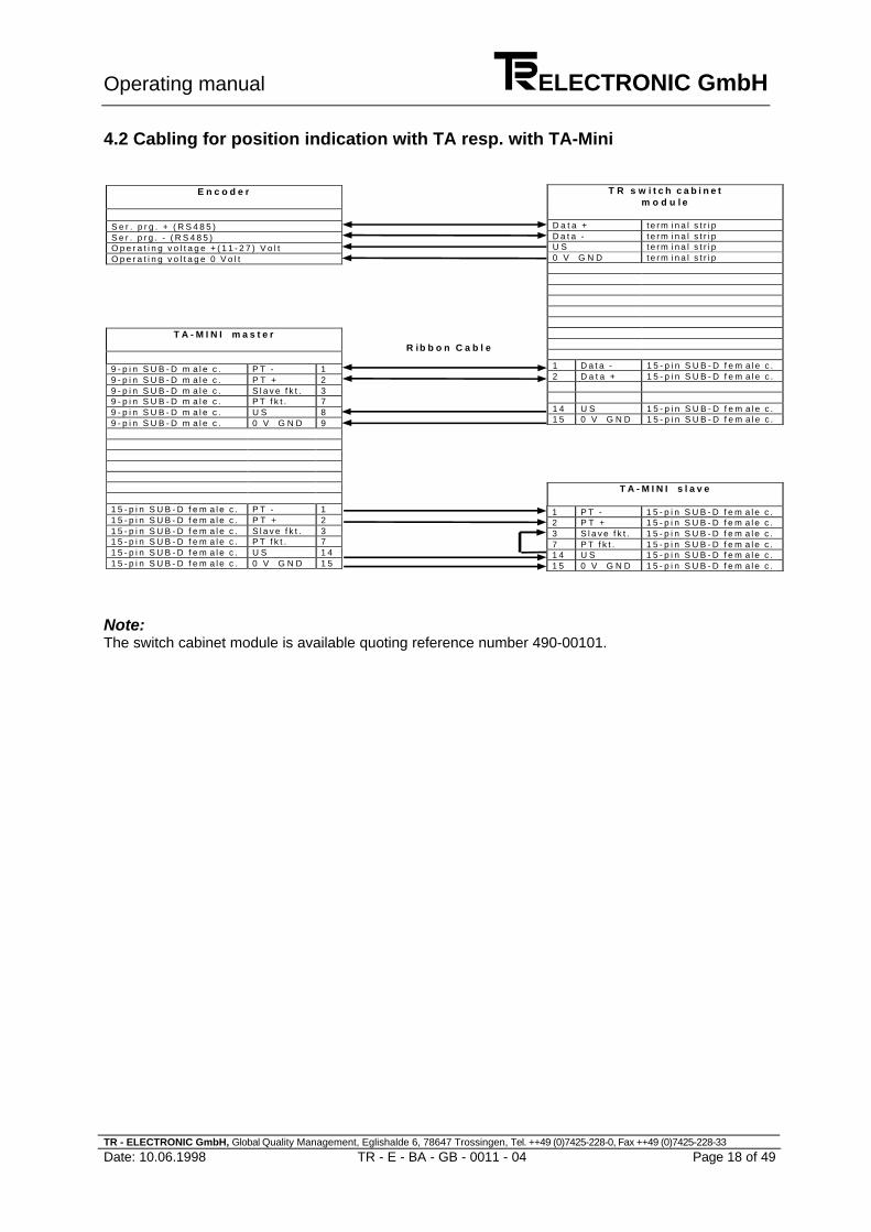
4.2 Cabling for position indication with TA resp. with TA-Mini
Note:The switch cabinet module is available quoting reference number 490-00101.
E n c o d e r
S e r . p r g . + ( R S 4 8 5 )S e r . p r g . - ( R S 4 8 5 )O p e r a t i n g v o l t a g e + ( 1 1 - 2 7 ) V o l tO p e r a t i n g v o l t a g e 0 V o l t
T R s w i t c h c a b i n e tm o d u l e
D a t a + t e r m i n a l s t r i pD a t a - t e r m i n a l s t r i pU S t e r m i n a l s t r i p0 V G N D t e r m i n a l s t r i p
1 D a t a - 1 5 - p i n S U B - D f e m a l e c .2 D a t a + 1 5 - p i n S U B - D f e m a l e c .
1 4 U S 1 5 - p i n S U B - D f e m a l e c .1 5 0 V G N D 1 5 - p i n S U B - D f e m a l e c .
T A - M I N I m a s t e r
9 - p i n S U B - D m a l e c . P T - 19 - p i n S U B - D m a l e c . P T + 29 - p i n S U B - D m a l e c . S l a v e f k t . 39 - p i n S U B - D m a l e c . P T f k t . 79 - p i n S U B - D m a l e c . U S 89 - p i n S U B - D m a l e c . 0 V G N D 9
1 5 - p i n S U B - D f e m a l e c . P T - 11 5 - p i n S U B - D f e m a l e c . P T + 21 5 - p i n S U B - D f e m a l e c . S l a v e f k t . 31 5 - p i n S U B - D f e m a l e c . P T f k t . 71 5 - p i n S U B - D f e m a l e c . U S 1 41 5 - p i n S U B - D f e m a l e c . 0 V G N D 1 5
T A - M I N I s l a v e
1 P T - 1 5 - p i n S U B - D f e m a l e c .2 P T + 1 5 - p i n S U B - D f e m a l e c .3 S l a v e f k t . 1 5 - p i n S U B - D f e m a l e c .7 P T f k t . 1 5 - p i n S U B - D f e m a l e c .1 4 U S 1 5 - p i n S U B - D f e m a l e c .1 5 0 V G N D 1 5 - p i n S U B - D f e m a l e c .
R ib b o n C a b l e

Operating manual ELECTRONIC GmbH
TR - ELECTRONIC GmbH, Global Quality Management, Eglishalde 6, 78647 Trossingen, Tel. ++49 (0)7425-228-0, Fax ++49 (0)7425-228-33
Date: 10.06.1998 TR - E - BA - GB - 0011 - 04 Page 19 of 49
5 Programming with EPROG
The EPROG PC program calls the input screen form from the connected device,displays it together with the actual values and transmits new entries back to thedevice where they are corrected, if applicable, and stored. The input screen form isalso called a dialog. It has a line structure and is divided into sections.
In the following, the individual sections of the CE dialog are explained. The name ofeach section corresponds to the entry in the title bar. Dialog lines can display fourdifferent kinds of values: integers, floating-point numbers, selections or text.Dialog lines with rarely required settings are only visible if extended options instead ofstandard options is selected in the first line.
The description refers to the programs C6HPC, C6HPCBN, C6HPCIJ, C6HPCPT andC6HPCNO. Depending on the program type and the equipment, some of the followingdialog lines and settings are not available.
5.1 Device section
Here, you will find the description of the device: the manufacturer, the program nameand date, the serial number and the production date.
5.2 Equipment section
Here, the equipment of the unit with interfaces and further type specific specialoptions as well as the limits for resolution and measuring range are displayed. This ispreset at the factory and cannot be changed afterwards without modification.
The dynamic camshaft gear can be used if the necessary additional memory isavailable.There can be 3 interfaces available and used at the same time: SSI, a 2nd interfaceand ISI. As 2nd interface is possible: parallel with 32, 24 or 12 outputs, 8 switchoutputs and Profibus.In the line Main disc the resolution is indicated as step number per revolution, inthe line Satellites the measuring range is indicated as number of revolutions.

Operating manual ELECTRONIC GmbH
TR - ELECTRONIC GmbH, Global Quality Management, Eglishalde 6, 78647 Trossingen, Tel. ++49 (0)7425-228-0, Fax ++49 (0)7425-228-33
Date: 10.06.1998 TR - E - BA - GB - 0011 - 04 Page 20 of 49
5.3 Axis name section
Here you can enter any text you like to describe the axis.
5.4 Stroke section
During a measurement, a physical measured quantity is converted to a measuredvalue. Since absolute encoders are trajectory measurement systems, the measuredquantity is an angle for rotating absolute encoders. In the following, it is indicated byrevolutions. The measured value is shown in steps.
To evaluate the measurement, the measuring range and the ratio between thephysical measured quantity and the measured value must be known. This ratio is alsocalled the resolution and limits measurement accuracy.
The resolution corresponds to the precision if the shaft couplings that the usermounted are not eccentric and he or she does overload the shaft radially and/oraxially.
To adapt the device to the application, you can program a reduced measuring rangeand/or resolution. It is even possible to extend the measuring range from 4096revolutions to up to 256000 revolutions. This is described in the Integer strokesection.
The measuring range is entered as the stroke in revolutions; the resolution resultsfrom the Stroke in steps or Steps per revolution entries.
Due to their construction, rotating absolute encoders jump back to the initial valuewhen the upper limit of the measuring range is exceeded and to the final value whenthe value falls below the lower limit of the measuring range.The following applies: Final value = initial value + stroke in steps - 1
In the Stroke line, you can choose from the following four types for programming themeasuring range and resolution:
5.4.1 Stroke, 1 rev.
The stroke is one revolution long. If no satellites are available, there are no otheroptions.

Operating manual ELECTRONIC GmbH
TR - ELECTRONIC GmbH, Global Quality Management, Eglishalde 6, 78647 Trossingen, Tel. ++49 (0)7425-228-0, Fax ++49 (0)7425-228-33
Date: 10.06.1998 TR - E - BA - GB - 0011 - 04 Page 21 of 49
5.4.2 Power of 2 stroke
With the power of 2 stroke, the length in revolutions must be a second power of thegroup of 20, 21, 2² etc. to 212 (or 1, 2, 4 to 4096). The number of revolutions and thesteps per revolution are entered in the subsequent lines.
If the number of steps per revolution is not an integer, but a decimal fraction withdecimal places, you must choose Fraction stroke and convert the entry asdescribed there (see below).
Example: You want to program 7031,1234 steps per revolution. Choosing 4096revolutions gives you the most precise result while avoiding the danger of a zero-point shift during zero-current travel. Set the denominator of the stroke in revolutionsto 1 and the stroke in steps to 7031,1234*4096. The rounded result will be 28799481.
5.4.3 Integer stroke
With the integer stroke, the length in revolutions is an integer between 1 and 256000.A second power as the measuring range can, for example, be unfavorable for rotatingapplications or decimal codes. Apart from that, programming is carried out as inPower of 2 stroke.
To extend the encoder's measuring range of 4096 revolutions, revolution bits 212 to217 which cannot be measured are incremented and decremented using the carries ofbits 28 to 211 and permanently stored every 28 revolutions in a FRAM. In thisconnection, a delay of up to 1600 revolutions may occur without leading to the loss ofa carry. If the encoder's extended measuring range of 218 revolutions cannot bedivided by the programmed measuring range without a remainder, the zero pointmust be displaced by this remainder and stored in the FRAM whenever the upper orlower limit of the measuring range is exceeded.
This means that with an integer stroke you must not operate the system at more than1600 revolutions if the encoder is switched off to avoid having to make areadjustment after switching on again. This restriction does not apply if the stroke inrevolutions is a second power of 20 to 212.
The data preservation and endurance of FRAM is described in more detail below inthe Preset inputs section.

Operating manual ELECTRONIC GmbH
TR - ELECTRONIC GmbH, Global Quality Management, Eglishalde 6, 78647 Trossingen, Tel. ++49 (0)7425-228-0, Fax ++49 (0)7425-228-33
Date: 10.06.1998 TR - E - BA - GB - 0011 - 04 Page 22 of 49
5.4.4 Fraction stroke
With the fraction stroke, the length in revolutions is a fraction. You enter thenumerator and the denominator in the subsequent lines as well as how many stepslong the stroke is to be. The numerator must be between 1 and 256000, thedenominator between 1 and 214 (or 16384). In addition, the fraction must not besmaller than ½. Zero-current travel is the same as with Integer stroke.
You cannot enter the number of steps per revolution directly. The value, which canalso have decimal places, must be multiplied by the stroke in revolutions, rounded upto the next integer and entered under stroke in steps.
5.4.5 Counting direction
Here, you must enter whether the position values are to be increased or decreased ifthe encoder is turned clockwise looking towards the shaft.
5.4.6 Initial value
In the Initial value line, you specify the type of initial value. If you do not want itto be zero, the following options are available:
Symmetrical sign means that half the measuring range is negative. Thus, theinitial value is the negative half of the stroke in steps.
Entry means that you can enter any negative or positive number as the initial value.
5.5 Preset inputs section
Here, you specify the selector values of the preset inputs, the starting edge, and theresponse time.
When the three preset inputs are connected to the starting edge, they trigger a zerodisplacement or adjustment. As a result, the position the device measured during thestarting edge afterwards corresponds to the selector value. To suppress interference,however, the preset is only carried out if the preset signal is present withoutinterruption during the entire response time. The starting edge and response time aremeasured with an accuracy of two milliseconds.
When the response time has elapsed, up to 50 milliseconds more will pass before thepreset adjustment is finished and affects the position. This period of time is neededfor storing and recalling the newly set zero point with checksum.
With extended options, the response time can be set between 10 and 255milliseconds. With standard options, this line is invisible and the response time is 50milliseconds.
If you do not need the preset inputs, you should inhibit them in the section's first lineto suppress interference. All the rest of the section will then become invisible.However, adjustment by means of EPROG in the Actual values section is stillpossible.

Operating manual ELECTRONIC GmbH
TR - ELECTRONIC GmbH, Global Quality Management, Eglishalde 6, 78647 Trossingen, Tel. ++49 (0)7425-228-0, Fax ++49 (0)7425-228-33
Date: 10.06.1998 TR - E - BA - GB - 0011 - 04 Page 23 of 49
If the Profibus transmission is set with 24 inputs and 8 outputs, the output bits 21 and22 will replace the 2nd and the 3rd preset input. These function can thus be started viathe Profibus.
The zero point adjusted by means of a preset is stored in a FRAM with 100 millionguaranteed write cycles. This means that it is possible to carry out a presetadjustment every three seconds for 10 years with the last zero point beingsubsequently retained for at least another 10 years. Two copies of the zero point arestored with checksums which makes it very unlikely that a failure to store that mayhave occurred will be undetected.
Slip drives with initiators at the end points of the travel path are a sensibleapplication. For rotating applications with known reduction ratio, you should rather usethe gearing programming in the Stroke section, since it works without loss ofaccuracy even at high traversing speeds.
5.6 PT/TA section
This section is only visible with extended options. Shall serial programming of theencoder with the handy terminal PT100 be possible or a slave indicator be connected,the suitable of the 5 possible types of PT100 must be set in the first line. Otherwise,the PT100 data exchange should be disabled as in other respects restrictions mayresult.
5.6.1.1 General restrictions for PT100 operation
Only one single interface is allowed. The stroke must always be indicated as gear. Itmay at most amount to 31*4096=126976 revolutions and 224=16777216 steps. Thedenominator of the revolutions may not exceed 99. The initial value may not besmaller than -223=-8388608. It must be so small that the final value stays below 224.The counting direction input cannot be switched off. The response time for the presetinputs is always 50 ms with the preset starting edge always rising. the 3rd preset inputis dropped. the maximum velocity is always 6000 rpm. The signal bits "Upward" and"Downward" as well as the switch outputs are dropped.

Operating manual ELECTRONIC GmbH
TR - ELECTRONIC GmbH, Global Quality Management, Eglishalde 6, 78647 Trossingen, Tel. ++49 (0)7425-228-0, Fax ++49 (0)7425-228-33
Date: 10.06.1998 TR - E - BA - GB - 0011 - 04 Page 24 of 49
5.6.1.2 Type specific restrictions for PT100 operation
PT100 SSI: Only SSI is allowed as an interface. The camshaft gear isdropped. As for the pine-tree format, signal bits may not comebefore the 24th SSI bit. After the SSI position data, at most 6signal bits can come. 2 signal bits are transmitted as switchoutputs.
PT100 ISI: Only ISI is allowed as an interface. The camshaft gear isdropped. The response time for the loading input is always 50 mswith the load starting edge always descending.
PT100 Parallel: Only parallel with 24 or 32 outputs is allowed as an interface.The camshaft gear is dropped. Only the first 24 outputs can beused.
PT100 18 cams: Only parallel with 24 or 32 outputs is allowed as an interfacewhereby only cams can be output. There are exactly 18 pathswith 1 cam each allowed.
The dynamic cams or lead times are dropped. The initial valuemust always be 0. The limit switch, inverting data, bus, latch,parallel 2^0 trigger and all signal bits are dropped.
PT100 29 cams: The encoder must be equipped with a main disc performing2,048 steps per revolution.
Only parallel with 24 or 32 outputs is allowed as an interfacewhereby only cams can be output. There are exactly 29 pathswith 1 cam each allowed. The stroke is always 1 revolution with360 steps.
The dynamic cams or lead times are dropped. The initial valuemust always be 0. The limit switch, inverting data, bus, latch andparallel 2^0 trigger and all signal bits are dropped except thefollowing: The 30th and the 31st parallel output are alwaysassigned with the signal bits "1=Moving“ und "0=Error“.
The 1st path serves as blue cam. That is, on wiring the 3rdpreset input, the cam is displaced in a way that its switch-offpoint coincides with the current position.
Switch-on and switch-off points of the cams may coincide, bywhich the cam always stays at 0.

Operating manual ELECTRONIC GmbH
TR - ELECTRONIC GmbH, Global Quality Management, Eglishalde 6, 78647 Trossingen, Tel. ++49 (0)7425-228-0, Fax ++49 (0)7425-228-33
Date: 10.06.1998 TR - E - BA - GB - 0011 - 04 Page 25 of 49
5.7 Signal bits section
This section is visible with extended options only. Here, you specify the allowedmaximum speed of the speed monitor and the switch-on and switch-off points of thefour limit switches.
The maximum speed must be between 30 and 6000 revolutions per minute. Withstandard options, the maximum value is used.
The position and number of the relevant signal bits are later set in the appropriatesections for every interface (see below for further explanations).
5.8 Cams section
The cams can be output instead of the position via all interfaces except ISI and switchoutputs. There are 32 paths with 4 cams per path possible.
The camshaft gear can be completely switched off if you select No in the title line.
5.8.1 Stroke
If Cams is selected in the Stroke line, a subsection is displayed where you can entera stroke for calculation of the respective cam position. The stroke is shown in theActual values section below the normal position. The subsection contains theMeasuring length in revolutions, Number of steps per revolutionand Origin lines.
You can only adjust the cam position indirectly via the normal position. The zero pointof the normal position is also cam position 0. However, this does not apply the otherway around, e.g. if the normal measuring range is 1024 revolutions and that of thecams is one revolution.
If you select Position in the Stroke line, the normal position is used as the camposition. Since for reasons of speed, the camshaft gear only works with 16 bits, this ispossible only if the stroke is a maximum of 65536 steps.
You should set the cam measuring range and resolution before entering the initial andfinal points of the cams, i.e. the switching points. In this way, you determine whichvalue range is permitted for the switching points. The initial value can always bemodified later, since the switching points are then adapted such that the cam patterndoes not change.

Operating manual ELECTRONIC GmbH
TR - ELECTRONIC GmbH, Global Quality Management, Eglishalde 6, 78647 Trossingen, Tel. ++49 (0)7425-228-0, Fax ++49 (0)7425-228-33
Date: 10.06.1998 TR - E - BA - GB - 0011 - 04 Page 26 of 49
In the Grid line, you can set a grid for the switching points. In this way, the switchingpoints and the cam position can be displayed with a resolution which is higher thanthat with cam output. The wider the grid, the faster the camshaft gear, because theposition values which lie between the grid points need not be processed. When thegrid is altered, the switching points present are shifted to the nearest grid point.The grid is at least one step in size. If you cannot see this line, it is exactly one step insize.
Notes:
If the encoder does not move too fast, in each cycle the camshaft gear moves onegrid point towards the new position. This guarantees that each switching point or camappears for at least one cycle in the output data. If the camshaft gear lags behind theposition by more than four grid points, the system issues the error Cam speed, setsthe error bits and outputs and carries out four steps per cycle. As a result, cams whichdo not exceed four grids can disappear. However, the remainder of the cams areoutput correctly up to the point where the speed is twice as high as it was when thecam speed error occurred for the first time. If the speed is increased further, theposition overtakes the camshaft gear, thus rendering the cams completely useless.
You should avoid at all costs operating the camshaft gear while the Cam speed erroris present. To remedy this, you must either reduce the cam resolution or increase thesize of the grid. You can calculate permissible values using the required maximumspeed from the table in the technical data in the appendix.
For example: You want a maximum speed of 1500 RPM or 25 revs/sec. Take a cycletime of 312.5 µs from the table. In one second, the camshaft gear can thus run1000000µs/312.5µs = 3200 grid points. As a result, a maximum of 3200/25 = 128 gridpoints may be dropped for each of the 25 revs/sec. If 1 grid point = 1 step, the camresolution may not be more than 128 steps per revolution. If, in addition, a camresolution of 4096 steps per revolution is required, you must enter a grid that is atleast 4096/128 = 32 steps in size.
After a preset adjustment or reprogramming of the encoder, which can result in achange in the position, the system may briefly issue the Cam speed error.
5.8.2 Advance times
If extended options are selected, dynamic cams can be programmed with fourdifferent advance times. At the beginning, the advance times are programmedbetween 0 and 70 milliseconds. For each track, you can specify the number of therelevant advance time for all of its switch-on and switch-off points. The switchingpoints are then issued by the respective time earlier than they are actually reached,i.e. they are advanced by a distance which is dependent on the speed. The purpose isto compensate for the response times at switching on and switching off of actuators ortools independently of the speed.

Operating manual ELECTRONIC GmbH
TR - ELECTRONIC GmbH, Global Quality Management, Eglishalde 6, 78647 Trossingen, Tel. ++49 (0)7425-228-0, Fax ++49 (0)7425-228-33
Date: 10.06.1998 TR - E - BA - GB - 0011 - 04 Page 27 of 49
5.8.3 Displacement
If you specify a positive or negative number in the Displacement line, all cams aredisplaced accordingly and the displacement is set to 0 again. The cams can also beshifted beyond the initial or final value without this leading to a changed cam pattern.
5.8.4 Tracks
In the Tracks line, you specify the desired number of tracks between 1 and 80. Foreach track, a subsection of its own appears. In the case of dynamic cams, theadvance times for the switch-on and switch-off point are selected first. Then youspecify the desired number of cams between 1 and 4. The corresponding number oflines for the switch-on and switch-off points appear.During entry of the switching points, overlapping cams and cams of zero length areautomatically corrected, starting with the first line. The cams can exceed the upperand lower limit of the stroke, i.e. the switch-on point can also be greater than theswitch-off point. Only cams of zero length, i.e. with the same switch-on and switch-offpoint or overlapping cams are not allowed.
5.9 SSI section
Functioning of the interface is described in the glossary section of the same name.The allowed line lengths and SSI clock frequencies are described in technical data inthe appendix.
5.9.1 Interface
In the 26-bits + repeat line you select whether with longer clock pulse bundlesthe data bits are to be repeated every 26 clock pulses or whether 0 bits are to betransmitted after the last data bit. Application: simple detection of transmission errors.
In the Tree format line you can select the so-called pine-tree format with 0, 12 or16 revolution bits if the type of data is called position. The number of steps perrotation must be a power of 2; the initial value must be 0, and you must select binarycode or Gray code. The revolution bits will then be right-justified in the 12 or 16 SSImost significant bits, followed by the central disk bits. Only if the stroke is onerevolution can you set the tree format to 0 bits.
Since data transfer is synchronized by the start of the clock pulse bundle, you caneasily use multi-step codes like binary code, for example.

Operating manual ELECTRONIC GmbH
TR - ELECTRONIC GmbH, Global Quality Management, Eglishalde 6, 78647 Trossingen, Tel. ++49 (0)7425-228-0, Fax ++49 (0)7425-228-33
Date: 10.06.1998 TR - E - BA - GB - 0011 - 04 Page 28 of 49
5.9.2 Data and signal bits
The total number of data and signal bits may not exceed 26 if SSI with 26-bit repeat isselected. Otherwise, the maximum value is 32.
5.9.3 Data bits
In the Data type line, you choose whether position values or cams are to be outputvia the SSI interface. It is not possible to do both at the same time. In the case ofcams, you need to program the cams appropriately in the previous Cam trackssection.
In the Data bits line, you specify the number of bits reserved for the position or thecams. They start at input bit 20.
In the case of position values, you specify in the Code line whether binary code, Graycode, clipped Gray code, BCD code, excess-three code, or clipped excess-three codeis to be used. If the number of data bits reserved for the position is not sufficient forBCD or excess-three code, the system automatically switches to binary code or Graycode. If it is still not sufficient, the relevant error message is issued. Then, you musteither reserve more data bits or decrease either the initial value, the measuringrange, or the resolution in the Stroke section described above.
If a negative initial value was selected in the Stroke section, you must specify in theNegative values line whether this value is to be represented as an absolute valueand sign or as a complement. The complement representation allows the user easiercalculating methods in adding and subtraction.
With negative numbers, the most significant position bit, which is used as the sign, isset in both forms of representation. Therefore, negative initial values mostly requirean additional data bit. The following table compares the complement representationand signed representation for binary and BCD code with 16 bits:
Value Binary+Compl. Binary+Sign BCD+Compl. BCD+Sign
2 0x0002 0x0002 0x0002 0x0002 1 0x0001 0x0001 0x0001 0x0001 0 0x0000 0x0000 0x0000 0x0000-1 0xFFFF 0x8001 0x9999 0x8001-2 0xFFFE 0x8002 0x9998 0x8002-3 0xFFFD 0x8003 0x9997 0x8003

Operating manual ELECTRONIC GmbH
TR - ELECTRONIC GmbH, Global Quality Management, Eglishalde 6, 78647 Trossingen, Tel. ++49 (0)7425-228-0, Fax ++49 (0)7425-228-33
Date: 10.06.1998 TR - E - BA - GB - 0011 - 04 Page 29 of 49
5.9.4 Signal bits
The data bit with the lowest value can be followed by up to 8 signal bits. You specifythe desired number in the Signal bits line. Then, two subordinate lines aredisplayed for every signal bit where you can select the type of signal and invert it ifrequired. The following signal types are available:
5.9.4.1 Upward movement, downward movement
This is a combination of direction indicator and zero-speed switch. The signal bit is setwhen the position moves in the corresponding direction and is deleted once it hasremained unchanged for 50 milliseconds.
To suppress vibrations, the movement detection has a hysteresis. With HE, thehysteresis is one step referred to the resolution of the central disk. After a reversal ofthe direction of movement, at least a distance corresponding to the hysteresis mustbe traveled before a movement or change in the direction of movement is signaled.The hysteresis also applies to the Previous upward movement and Ongoingmovement signals explained below:
5.9.4.2 Previous upward movement
The signal bit is set when Upward movement is set and it is deleted when Downwardmovement is set.
5.9.4.3 Ongoing movement
The signal bit is set while either Upward movement or Downward movement is set.
5.9.4.4 Static and dynamic error (watchdog)
As long as the position data can be measured and transmitted without errors, thesignal bit Static error is deleted and the signal bit Dynamic error supplies asquare-wave frequency of 250 Hz. In the case of an error, the Static error is setand the Dynamic error stays at any level.
You should use the dynamic error instead of the static one if possible, since thedynamic error is very likely to also detect faulty program execution in the device.
In the case of an error, the cause of the error is displayed in plain text in the Actualvalues section. The description of this section contains a list of possible errors andtheir remedies (see below). Overspeed is also indicated as an error there; however,it does not trigger static and dynamic error.

Operating manual ELECTRONIC GmbH
TR - ELECTRONIC GmbH, Global Quality Management, Eglishalde 6, 78647 Trossingen, Tel. ++49 (0)7425-228-0, Fax ++49 (0)7425-228-33
Date: 10.06.1998 TR - E - BA - GB - 0011 - 04 Page 30 of 49
5.9.4.5 Maximum speed
The signal bit is set when the maximum speed set in the Signal bits sectionabove is exceeded. This signal type is available with extended options only.
5.9.4.6 1st to 4th limit switch
The signal bit of a limit switch is set while the position is on or above the switch-onpoint and below the switch-off point. The switching points are entered in the Signalbits section above.
The switch-off point must be greater than the switch-on point. If the opposite case isrequired, you must reverse the two switching points and invert the signal bit.
This signal type is available with extended options only.
5.9.4.7 Even parity, even error parity
You receive uneven parities by inverting the bit pattern.
If no encoder error is present, the error parity corresponds exactly to the normalparity. In the case of an error, it is inverted. Its purpose is to make additionaltransmitting of the encoder error unnecessary.
If for SSI a signal bit Parity or Parity error is desired, it must be at the last digit. It iscalculated from all previous bits. Therefore, only one single parity bit is possible. Forother interfaces see section "Data and signal bits".

Operating manual ELECTRONIC GmbH
TR - ELECTRONIC GmbH, Global Quality Management, Eglishalde 6, 78647 Trossingen, Tel. ++49 (0)7425-228-0, Fax ++49 (0)7425-228-33
Date: 10.06.1998 TR - E - BA - GB - 0011 - 04 Page 31 of 49
5.10 ISI section
Functioning of the interface is described in the glossary section of the same name.
You make these settings for the load input in lines Load start edge andResponse time. In line Highest frequency, you enter the highest frequencythat the incremental counter connected to the encoder can still acquire.
At some encoders the ISI outputs can be made tristate via a bus input. Then the lineTristate appears. There you must normally select Never.
At some encoders the ISI outputs can be locked against upward and downwardmovement after the loading procedure. The point is to hide a slight backwardmovement from the control system at gears with much floating after the axis hasstopped. These encoders display the Count direction line. There you mustnormally select Upward & downward.
Notes:
Since the incremental counter does not get a valid position during loading, you shouldonly position or regulate the axis when the encoder has switched the loading input to0 thus indicating the end of loading. Traversing the axis during the loading processdoes not, however, distort the position value loaded in the incremental counter.
After completing loading, the encoder behaves like a normal incremental encoder.This means that when it runs over the start or the end value, the incremental encodercontinues to run in the direction of traversing. Since the absolute position jumps to theopposite limit value, it no longer matches the reading of the incremental encoder.
To suppress disturbing pulses that are stored in the incremental counter, loadingshould be repeated at regular intervals, e.g. when the axis in question is idle.
Negative position values can also be loaded in the incremental counter, e.g. if thestart value is negative. If the signs of the displayed absolute position and theincremental counter reading are different, you must reverse lines K1 and K2.
If the encoder does not issue any pulses when traversing the axis, it is probablywaiting for the load start edge. You can remedy this by reprogramming the edgedirection.
If the connected incremental counter frequently contains faulty values, you shouldreduce the maximum frequency that is programmed in the axis cassette. Apart fromthis, the system must have good interference suppression characteristics. Theincremental signals should be transferred differentially with TTL levels via twisted-pairwires. All the cables, particularly the power cables on frequency converters, must befitted with screens grounded on both ends (see wiring notes at the beginning). Withpersistent disturbances use SSI by preference.

Operating manual ELECTRONIC GmbH
TR - ELECTRONIC GmbH, Global Quality Management, Eglishalde 6, 78647 Trossingen, Tel. ++49 (0)7425-228-0, Fax ++49 (0)7425-228-33
Date: 10.06.1998 TR - E - BA - GB - 0011 - 04 Page 32 of 49
5.11 Section Digital outputs
Different from the parallel interface, the up to 8 switch outputs cannot output positiondata, cams or parities. However, limit switches are possible with extended options.
The inputs for inversion, latch and bus do not effect the switch outputs. By that theycan always indicate the latest state of signal bits such as limit switch or error, even ifthe outputs of the parallel interface are momentarily inverted, frozen or tristate.
The switch outputs can also be present with disconnected or missing parallelinterface. However, you must check by means of the pin assignment which ones areactually connected at the pin.
Programming the signal bits is done in the same way as described in section SSIabove, yet with the parities being dropped.
If the encoder has a parallel interface with 32 outputs, the last 8 can be turned intoswitch outputs by selecting Output 25 - 32 instead of No in the Digitaloutputs line.
5.12 Parallel interface section
Functioning of the interface is described in the glossary section of the same name.
5.12.1 Interface
5.12.1.1 Inverting function
In the Inverted line, it is indicated when the data bits are output invertedly. Nomeans never, Yes means always. 0V=No means that the data bits are outputnormally with 0 V at the inverting input but invertedly with US level. 0V=Yes is theopposite case. The user can check by short inverting if the inputs, the encoderoutputs and the cable are all right.
5.12.1.2 Bus function
In the Tristate line, the bus function is set. 0V=No means that the data outputs atthe bus input are switched on with 0 V but switched off or tristate with US level.0V=Yes is the opposite case. If never is selected, the data outputs never are tristate,i. e. there is no bus function.
For safe data transfer we recommend to freeze the data outputs on switching themon. The bus and the latch input must then be connected with each other andprogrammed the other way round, e. g. 0V=No for the bus function and 0V=Yes forthe latch function.
Operating manual ELECTRONIC GmbH
TR - ELECTRONIC GmbH, Global Quality Management, Eglishalde 6, 78647 Trossingen, Tel. ++49 (0)7425-228-0, Fax ++49 (0)7425-228-33
Date: 10.06.1998 TR - E - BA - GB - 0011 - 04 Page 33 of 49
5.12.1.3 Latch function
In line Latch, you set the latch function. 0V=No means that at 0 V at the latch inputthe data outputs always state the latest values; with a US level, the outputs are frozenor latched and can be read continuously by the user. With 0V=Yes, the oppositeapplies. If never is selected, the data outputs never are frozen, i.e. there is no latchfunction.
The latch function is important when using multi-step codes, i.e. if several data bitscan change at the transition to the next position. If the user reads the data bits duringone of these transitions instead of freezing them, a situation can arise in which theuser only obtains the new status for a few of the data bits. This can lead tononsensical position values. With binary code, for example, the transition from 0x1FFto 0x200 often results in a faulty read out of 0x2FF or 0x100, depending on thedirection. With decimal codes, pseudo tetrads can occur, i.e. illegal bit combinations.
If you use long cables, the capacity between the lines can result in crosstalk. Thismeans that when a parallel encoder switches other wires may take the same level.This can be remedied by freezing the data before reading it.
The response time for freezing data is 20 µs; the time for unfreezing or refreshing is100 µs. The delay times on the user's side for the latch output and the input filtersmust be added to the response time for freezing. If these amount to e.g. 200 µsaltogether, the latch input must be switched to freezing at least 220 µs before readingthe data.
5.12.1.4 Dynamic strobe
If you expects a strobe signal indicating the validity of data, you can help yourself bytaking a slight detour as follows: Program a switch output of the encoder as adynamic error so that it transmits a symmetric rectangular signal with a period of 4milliseconds in normal operation. This is led to the latch input of the encoder and tothe strobe input of the user. If the latch function is set to 0V=No, 0 V means invaliddata and US level means valid data with the strobe signal. For 0V=Yes it is the otherway round.
Mind that for the strobe output of the encoder a switch output is used instead of asignal bit of the parallel output, as otherwise it is frozen as well.

Operating manual ELECTRONIC GmbH
TR - ELECTRONIC GmbH, Global Quality Management, Eglishalde 6, 78647 Trossingen, Tel. ++49 (0)7425-228-0, Fax ++49 (0)7425-228-33
Date: 10.06.1998 TR - E - BA - GB - 0011 - 04 Page 34 of 49
5.12.1.5 20 strobe
Some control systems avoid reading the position data during the transitions by takingover this short time after a level change on the 20 bit and thereby using a binary orBCD code.
This however creates the problem that sometimes data bits can change without the 20
bit changing the level. This can occur after switching on, after a preset adjustment orwith processes at such a high velocity that the encoder must skip position values onoutputting data. The control system then operates with old or even invalid positionvalues.
If such a control system is used, the 20 strobe should be switched on. The encoderthen switches the 20 bit after switching on and with every data output if any data bithas changed.
The 20 strobe is only possible when latch and bus function are disabled, when binaryor BCD code have been selected and when no signal bit dynamic error is used.
5.12.1.6 Continuous progressive codes
You can use continuous progressive codes for parallel data transfer for readingwithout synchronization by latch or strobe signals. You must select clipped codes, i.e.shifted Gray code or shifted Gray excess-three code, so that also the transition frominitial to final value turns out continuously.
When using shifted Gray code, the used value range i.e. the measured length in stepsis rounded up to the next bigger 2-potency. The value range is then laid centricallyinto this 2-potency by adding half the difference between 2-potency and value rangebefore data output. After decoding on the user's side, this value must be subtractedagain to obtain the actual position.Example: For the shifted Gray code with 360 steps, half the difference is(29-360)/2=(512-360)/2=76.
For the shifted Gray excess-three code, you round up to the next 10-potency.Example: For the shifted Gray excess-three code with 720 steps, half the difference is(103-720)/2=(1000-720)/2=140.
Shifted code is only possible with the initial value being 0.

Operating manual ELECTRONIC GmbH
TR - ELECTRONIC GmbH, Global Quality Management, Eglishalde 6, 78647 Trossingen, Tel. ++49 (0)7425-228-0, Fax ++49 (0)7425-228-33
Date: 10.06.1998 TR - E - BA - GB - 0011 - 04 Page 35 of 49
5.12.2 Data and signal bits
Selection of data and signal bits is made in the same way as described in section SSIabove, but with the following variations:
Up to 8 signal bits can follow the data bit of maximum value. If signal bits havealready been selected for SSI, their number is subtracted from the maximum value 8.
The parity is calculated from the data bits only, i.e. either cams or position with sign ifexisting. All other bits are not considered. Several parities can be output.The total number of data and signal bits may not exceed the number of outputsspecified in the equipment of 12, 24 or 32. If the last 8 parallel outputs have beenturned into switch outputs in section switch outputs, the maximum number of data andsignal bits is reduced by 8 again. In addition, you must check by means of the pinassignment how many outputs are actually connected to the pin.
If the last 8 parallel outputs have been turned into switch outputs, the inputs forinverting, latch and bus have no more effect on them. Programming them is done inthe previous section Digital outputs.
5.13 Profibus DP section
Functioning of the interface is described in the glossary section of the same name.
Chapters 4 and 5 of the manual entitled Distributed Peripheral System ET22 containsupplementary information about additional line lengths and installation of theProfibus. You can obtain this manual from Siemens quoting reference numberEWA 4NEB 780 6000-01.
5.13.1 Interface
The Profibus interface is equipped with component LSPM2. The LSPM2 automaticallyadapts to the baud rate in use. As standard, it is possible to use all the baud rates from9.6 kbps to 1.5 Mbps; 3 to 12 Mbps are available as an option.
Through the window in the encoder cover you can see a green LED "NORMOPER"and a red LED "DIAERROR". On removing the cover, there are two BCD switchesand two DIP switches besides the terminals accessible. The BCD switches allow toset the station address for the Profibus, the DIP switches allow to set the terminator orthe bus moving load. If the station is the last one on the bus line, these switches mustbe set to ON; in all other cases, they must be set to OFF.

Operating manual ELECTRONIC GmbH
TR - ELECTRONIC GmbH, Global Quality Management, Eglishalde 6, 78647 Trossingen, Tel. ++49 (0)7425-228-0, Fax ++49 (0)7425-228-33
Date: 10.06.1998 TR - E - BA - GB - 0011 - 04 Page 36 of 49
If you choose 32 I in the Inputs/Outputs line, from the point of view of the PLC,the station has 0 output bytes and four consistent input bytes. When configuring theSiemens Profibus IM308 module, you must specify values 000 and 147.
If you choose the value 8 O. + 24 I, the station has one output byte and threeconsistent input bytes and you must enter the values 160 and 146 for configuration ofthe IM308. The purpose of this setting is to trigger the second and third electricalpreset by means of bits 21 and 22 via the Profibus. Then the corresponding inputs nolonger have an effect. In this context, the preset function must be enabled and theselector values, starting edge, and response time set appropriately in the previousPreset inputs section.
In the case of a general error, diagnosis bit 27 is set; in the case of overspeed,diagnosis bit 26 is set. If the red DIAERROR LED lights up, at least one diagnosis bitis set. If the green NORMOPER LED lights up, the station is being addressed via theProfibus. This is also displayed by EPROG in the Actual values section.
Since data transfer is synchronized by the Profibus telegram, you can use multistepcodes such as the binary code without problems. However, if the Profibus connectionon the user's side has problems in consistent reading, you can avoid this by usingclipped continuous progressive codes.
Notes:
Detailed notes about connecting to a Profibus connection IM308 by Siemens areavailable quoting reference number TR-ECE-TI-GB-0009.
Quoting reference number 490-00405 there is a floppy disk available, containing thetype files for the configuration program COM-ET-200 by Siemens. The above-mentioned notes are also included as a WINWORD 6.0 file. These files can bedownloaded gratuitously from the TR mailbox.
Only the terminals DataA und DataB must be connected for the Profibus. These areexisting twice in the cover for the lines to the previous and to the subsequent station.The terminals M5V2 must remain open.
5.13.2 Data and signal bits
Selection of data and signal bits is made in the same way as described in section SSIabove, but with the following variations:
Up to 8 signal bits can follow the data bit of maximum value. If signal bits havealready been selected for SSI, their number is subtracted from the maximum value 8.
The parity is calculated from the data bits only, i.e. either cams or position with sign ifexisting. All other bits are not considered. Several parities can be output.Depending on the setting of Inputs/Outputs, the total number of data and signalbits may not exceed 24 or 32.

Operating manual ELECTRONIC GmbH
TR - ELECTRONIC GmbH, Global Quality Management, Eglishalde 6, 78647 Trossingen, Tel. ++49 (0)7425-228-0, Fax ++49 (0)7425-228-33
Date: 10.06.1998 TR - E - BA - GB - 0011 - 04 Page 37 of 49
5.14 Section Analog outputs
The analog output is potentially separated from the supply terminals of the encoder.The load must be connected between analog+ and analog-. If the analog output isused as a voltage output, the load must be at least 500 Ohm. If the analog output isused as a power output, the load may not exceed 500 Ohm. As a result, themaximum values for output voltage resp. power amount to 10 V and 20 mA.
The first line Analog outputs indicates how many of the existing analog outputsshall be used. 0 disconnects them completely.
A separate section appears for each analog output. The line X. Analog outputindicates whether voltage (-10…+10 V) or power (0…20 mA) shall be output. Thenthe analog units used are millivolts "mV" resp. microampere "µA".In line Data type, you select as input quantity to which the analog signal shallcorrespond, either position or velocity. In the lines Initial value and Finalvalue, you set the ranges for the input quantity and the analog output signal. Thevolume of the ranges is the difference between the limit values, i.e. between the finaland the initial values.
If the input quantity is in its range, the analog signal moves in a linear way from theinitial to the final value. If the input quantity exceeds its range, the analog signal staysat the corresponding limit value.The final value for the input quantity and the analog signal may not be smaller thanthe initial value.Adjustment to the various analog interfaces is made by suitable selection of theanalog initial and final values, e.g. 4000…20000 µA for 4…20 mA,-5000…5000 mV for -5…+5 V or 0…10000 mV for 0…10 V.
The resolution of the analog output normally is 14 bit for the whole output range of20 V or 20 mA, which results in steps of 1.2 mV or µA.This resolution, however, is only utilized in the largest possible range of the analogsignal if the range of the input quantity is selected at least 214 steps large. Onreducing the analog range, this value is diminished linearly.
1st example: The input range shall be 20 steps large, the output range 20 V. Theoutput voltage then runs in steps of 1 V from the initial to the final value.
2nd example: The input range shall be 20 steps large, the output range 10 mV. Thenthe output voltage should run in steps of 0.5 mV from the initial to the final value.Actually, the next smaller possible step is then output so that the steps are 1.2 mV.
3rd example: The input range shall be 0 steps large, i.e. its initial and final value shallbe equal. The output voltage then jumps from the analog initial value to the analogfinal value.

Operating manual ELECTRONIC GmbH
TR - ELECTRONIC GmbH, Global Quality Management, Eglishalde 6, 78647 Trossingen, Tel. ++49 (0)7425-228-0, Fax ++49 (0)7425-228-33
Date: 10.06.1998 TR - E - BA - GB - 0011 - 04 Page 38 of 49
5.14.1 Latch function
In line Latch, you set the latch function. 0V=No means that the analog output alwaysindicates the latest value with 0 V at the latch input, but is frozen or latched with USlevel and can be read stably by the user. 0V=Yes is the opposite case. If Never isselected, the analog output is never frozen, i.e. there is no latch function.
The response time of the latch input for freezing the analog output is 20 µs, forunfreezing or refreshing 100 µs. The delay times on the user's side for the latchoutput and the input filters must be added to the response time for freezing. If theseamount to e.g. 200 µs, the latch input must be switched to freezing at least 220 µsbefore reading the data.
5.14.2 Inversion function
Line Inverted specifies in which cases the analog signal is output invertedly. 0V=Nomeans that the analog signal is output normally with 0 V at the inversion input, butinvertedly with US level. 0V=Yes is the opposite case. If Never is selected, theinversion input is switched off. The user can check by quick inversion if the inputs,encoder outputs and the cable are all right.
NoteThe inversion function is available with voltage output only.

Operating manual ELECTRONIC GmbH
TR - ELECTRONIC GmbH, Global Quality Management, Eglishalde 6, 78647 Trossingen, Tel. ++49 (0)7425-228-0, Fax ++49 (0)7425-228-33
Date: 10.06.1998 TR - E - BA - GB - 0011 - 04 Page 39 of 49
5.15 Actual values section
5.15.1 Position
The currently output position is displayed here. An adjustment can be carried out byentering a new value, which must, however, be stored afterwards (see chapter"Program EPROG" up to page 11).
If cams are available, the cam position is additionally displayed, since the cammeasuring range and resolution may differ from the normal position calculation.However, the cam position can only indirectly be adjusted via the normal position. Atthe zero point of the normal position, the cam position is 0 too. However, this does notapply the other way round, for example if the normal measuring range is 1024revolutions and the one for the cams is one revolution.
5.15.2 Velocity
The velocity is displayed here: for rotating encoders in RPM, for linear encoders inmm/sec.
5.15.3 Errors
If proper measurement and transmission of the position data are at risk or impossible,the cause is displayed here. A list of possible errors and measures to remove them isgiven below. Unless specified otherwise, the error need not be acknowledged ordeleted, but must simply be removed. Then the error message will automaticallydisappear and the Error signal bit will be deleted. Apart from overspeed, all theerrors listed here lead to setting of the Error signal bit and the fall of the Ready-for-operation relay. This state has a signal bit of its own.

Operating manual ELECTRONIC GmbH
TR - ELECTRONIC GmbH, Global Quality Management, Eglishalde 6, 78647 Trossingen, Tel. ++49 (0)7425-228-0, Fax ++49 (0)7425-228-33
Date: 10.06.1998 TR - E - BA - GB - 0011 - 04 Page 40 of 49
5.15.3.1 Components
The self-diagnosis which is carried out at start-up has identified defectivecomponents. The device must be replaced.
5.15.3.2 Central disk
The rotating encoder abruptly changed its direction of travel. This can be caused byloose contacts in the encoder cable, wrong programming of the encoder resolution(see rating plate), very strong vibrations, electrical interference, excess axial andradial forces on the shaft, or scanning problems. You can first delete the error byresetting the encoder by means of EPROG (see chapter "Program EPROG" up topage 11) or by switching the encoder off and then on again.
Insulating flanges and couplings made of plastic as well as cables with twisted-paircores for clock pulse, data, and supply are measures against electrical interference.The cable shields should be grounded on both sides. Only if the machine ground isheavily contaminated with interference towards the control cabinet ground should theshield be grounded in the control cabinet only. Plastic couplings preventmechanical strain of the shaft. Vibrations and impact stress, for example at presses,are dampened by means of "shock modules". If the error continues to occur despitethese measures, the encoder must be replaced.
5.15.3.3 Satellite
The rotating encoder made a very large step change. This can be caused by loosecontacts in the encoder cable, wrong programming of the encoder measuring range(see rating plate), electrical interference or scanning problems. For measures, refer tocentral disk error (see above).
5.15.3.4 FRAM checksum
The checksum for the characteristic values stored in FRAM is not correct. If the errorcannot be removed by programming the device by means of EPROG (see chapter"Program EPROG" up to page 11), the FRAM is defective and the device must bereplaced.
5.15.3.5 Cam speed
The speed is so high that the cams' switching points can no longer be processed intime. It is normal that this error occurs for a short period of time after an adjustmentor preset. If this error message is issued continuously, the speed must be reducedand the cam output must be increased. To do so, switch off interfaces and optionssuch as limit switches which are not used. Should this not work, the cam resolutionmust be reduced or the cam grid must be made wider (see above section Cams).

Operating manual ELECTRONIC GmbH
TR - ELECTRONIC GmbH, Global Quality Management, Eglishalde 6, 78647 Trossingen, Tel. ++49 (0)7425-228-0, Fax ++49 (0)7425-228-33
Date: 10.06.1998 TR - E - BA - GB - 0011 - 04 Page 41 of 49
5.15.3.6 Warm restart
The device continuously checks the settings of its ports and the contents of its RAM.If it detects unreasonable or invalid states, it assumes that electrical interference ispresent and carries out a warm restart for re-initialization. If this occurs frequently, thedevice's interference must be suppressed as described above in Central diskerror.
5.15.3.7 Overspeed
The speed monitor has detected that the maximum speed programmed in theSignal bits section has been exceeded. Action: reduce speed or increase speedlimit. This is the only error that does not lead to setting of the Error signal bit, butonly to setting of the Overspeed signal bit.
5.15.3.8 Analog outputs
The analog outputs are lined up digitally in the factory and the correction values arestored in EEPROM. On switching on, the encoder checks if the correction values arein the acceptable range. Otherwise, the error message "Analog outputs" appears. Thisis a manufacturing error. The unit must be replaced.
5.15.4 Interfaces
For every active interface, the currently output bit pattern is displayed here by meansof 0 and 1. If a short circuit is detected on a bit, a normal comma or an invertedcomma appears depending on whether the nominal value is 0 or 1. However, thisdiagnosis is not possible with all bits.
With the SSI bit pattern, 32 bits are displayed with simple transmission while only 26bits are displayed with multiple transmission. The display is left-justified as is thetransmission, i.e. the data occupies the more significant bits and the less significantbits are padded with zeroes.
At the parallel interface, the latch function has also an effect on the displayed bits. Ifthe outputs are frozen, the display remains as well even if the encoder is moving.
With the Profibus interface, you can additionally see whether the station is currentlybeing addressed via the bus.

Operating manual ELECTRONIC GmbH
TR - ELECTRONIC GmbH, Global Quality Management, Eglishalde 6, 78647 Trossingen, Tel. ++49 (0)7425-228-0, Fax ++49 (0)7425-228-33
Date: 10.06.1998 TR - E - BA - GB - 0011 - 04 Page 42 of 49
6 Appendix
6.1 Dimensioned drawing, pin assignment, available options
See specification sheet of the respective encoder.
6.2 Technical data
6.2.1 Power supply
Because of the filter capacitors of the devices, you need not take into considerationthe residual ripple of the supply voltage while the voltage remains within the allowedrange.
With devices containing switching power supplies, the input power is hardlydependent on the supply voltage, i.e. the higher the supply voltage, the more theinput current increases until the switching power supply switches off. As follows, thesupply voltage with the highest current consumption and the current consumption atthe highest supply voltage are specified, together with the current consumption at thelowest acceptable operating voltage. Possibly existing parallel outputs are unloadedin this case. the current consumption increases depending on the load.
The listed guaranteed maximum values for current consumption are 120% of typicalvalues.
At power-on of the supply voltage, the charging current for the filter capacitors of thedevices (maximum of 300 microfarad per device) must be provided in addition to thespecified maximum input current.
With long cables the ohm voltage drop on the up-and-down-line must be taken intoaccount. Example: With 500 m of copper strand of 0.5 mm², resistance is 18 Ω. At280 mA, the supply voltage of the encoder decreases by 2*18 Ω*0.28 A = 10.1 V.Thus, a minimum of 11+10.1 V = 21.1 V must be supplied.
Supply voltage: 11-27 VTemperature range: 0...+60° C standard, -20...+70° C on request
6.2.1.1 CE65 SSI
Input current at 8V: max. of 280 mAInput current at 11V: max. of 190 mAInput current at 27V: max. of 120 mA
6.2.1.2 CE65 SSI+parallel 32xUS level
Input current at 8V: max. of 280 mAInput current at 11V: max. of 220 mAInput current at 27V: max. of 150 mA
Operating manual ELECTRONIC GmbH
TR - ELECTRONIC GmbH, Global Quality Management, Eglishalde 6, 78647 Trossingen, Tel. ++49 (0)7425-228-0, Fax ++49 (0)7425-228-33
Date: 10.06.1998 TR - E - BA - GB - 0011 - 04 Page 43 of 49
6.2.1.3 CE65 SSI+ISI
Input current at 8V: max. of 410 mAInput current at 11V: max. of 280 mAInput current at 27V: max. of 160 mA
6.2.1.4 CE65 SSI+Profibus
Input current at 8V: max. of 460 mAInput current at 11V: max. of 330 mAInput current at 27V: max. of 160 mA
6.2.1.5 CE65 SSI+analog output
Input current at 8V: max. of 410 mA with 500 Ω loadInput current at 11V: max. of 310 mA with 500 Ω loadInput current at 27V: max. of 160 mA with 500 Ω load
6.2.2 Times
Average cycle time (1 interface, no options) 300 µsMaximum cycle time (all interfaces and options) 500 µsFreeze parallel/analog outputs (activate latch) 20 µsUnfreeze parallel/analog outputs (deactivate latch) 100 µsPeriod from dynamic error output (symmetrical rectangle) 4000 µs
6.2.3 Clock frequency for SSI output
6.2.3.1 SSI clock frequency and monoflop time
The system routes the clock pulses to a retriggerable monoflop and detects the startand end of the bundle of clock pulses. For this to function safely, the clock frequencymust be at least 2/monoflop period and the space between the bundles of clockpulses must be at least 2*monoflop period.
Monoflop period 21 µsMinimum frequency for SSI clock pulse 95 kHzMinimum space between SSI bundles of clock pulses 42 µs

Operating manual ELECTRONIC GmbH
TR - ELECTRONIC GmbH, Global Quality Management, Eglishalde 6, 78647 Trossingen, Tel. ++49 (0)7425-228-0, Fax ++49 (0)7425-228-33
Date: 10.06.1998 TR - E - BA - GB - 0011 - 04 Page 44 of 49
6.2.3.2 SSI clock frequency and line lengths
The listed guaranteed maximum values for the SSI clock frequency are 75% oftypical maximum values. They are applicable with a symmetrical clock pulse signal.With a non-symmetrical clock pulse, the maximum frequencies or the line lengths arereduced.
The following assumptions are made: a cable is used comprising twisted-pair wireswith a common sheath and a cross-section of at least 0.25 mm²; an RS422 or anRS485 cable transmitter is used as the clock pulse transmitter and fast optocouplers,with an amplifier like a 6N137, for example, are used as the data receiver. It is notadvisable to use RS422 cable receivers instead of the optocouplers. It is true that thiscan slightly increase the clock pulse frequencies; however, due to the lack of potentialseparation, the signals are more susceptible to disturbances. In addition, reversingthe polarity of the encoder can damage it and the connected electronics.
If the clock pulse lines to the encoder are mixed up, data is delayed by half a clockpulse period. The MSB arrives on the second or third clock edge. You must setoptimum clock pulse polarity so that the system shifts and reads the data on the sameclock pulse edge. If different edges are used for this, the connected electronics hasonly half a clock pulse period instead of a full one to read a data bit and the allowedclock pulse frequency is halved.
Line length up to Maximum allowed SSI clock pulse frequency
12.5 m 819 kHz25 m 756 kHz50 m 578 kHz
100 m 364 kHz200 m 228 kHz300 m 163 kHz400 m 127 kHz500 m 105 kHz
6.2.3.3 Optimum SSI clock pulse polarity
To find out the optimum SSI clock pulse polarity, you must first find out whether thesystem reads the SSI data bits on the first, the third and the other odd-numberedclock pulse edges or on the even-numbered edges. For this, you connect the AK witha short cable.
Turn the encoder one rotation, make a note of the change in the received positionvalue that this produces, reverse the polarity of the clock pulse and repeat theprocedure. If, while doing this, you find out that a change is only half as great as theother one, the system is reading the odd-numbered clock pulse edges. In this case,use the polarity with the smallest change.
If there is no difference between the changes, you must carry out oscillographinspection of the clock pulse and the data together. Trigger on the pulse and noticethe polarity on which the data comes half a clock pulse earlier. In this case, the dataedges coincide with the even-numbered clock pulse edges and polarity is optimized.

Operating manual ELECTRONIC GmbH
TR - ELECTRONIC GmbH, Global Quality Management, Eglishalde 6, 78647 Trossingen, Tel. ++49 (0)7425-228-0, Fax ++49 (0)7425-228-33
Date: 10.06.1998 TR - E - BA - GB - 0011 - 04 Page 45 of 49
6.2.4 Instructions for cabling
For SSI and RS485 signals, you should choose leads of at least 0.25 mm2, for supplyat least 0.5 mm2. This is especially true for cables of more than 100 m in length. Youshould use twisted pair leads for this purpose. It is recommended to use shieldedcables which are grounded on both sides to protective earth or to frame ground.
Chapters 4 and 5 of the manual entitled Distributed Peripheral System ET22 containsupplementary information about additional line lengths and installation of theProfibus. You can obtain this manual from Siemens quoting reference numberEWA 4NEB 780 6000-01.
6.3 Accessories
TR-ECE-TI-D-0009 Description (German): Instructions for Siemens IM308 Profi-bus interface module
TR-ECE-TI-GB-0009 Description (English): Information on the Siemens IM308Profibus interface module
490-00301 Equipment: PC Adaptor
490-00404 3.5“ floppy disk: EPROG program
490-00405 3.5“ floppy disk: Profibus support files for SiemensCOM-ET-200
490-00101 TR-PT-6: control box module for PT-100 connection
485-00001 TA-MINI: 6-digit display for actual data

Operating manual ELECTRONIC GmbH
TR - ELECTRONIC GmbH, Global Quality Management, Eglishalde 6, 78647 Trossingen, Tel. ++49 (0)7425-228-0, Fax ++49 (0)7425-228-33
Date: 10.06.1998 TR - E - BA - GB - 0011 - 04 Page 46 of 49
6.4 Glossary
Explanation of technical terms
6.4.1 Absolute encoder
A device for position measurement. The supplied measured value contains thecomplete position as an analog or digital value.
By contrast with an absolute encoder, an incremental encoder signals changes inposition only by counting-pulses with information on the direction of rotation whichmust be detected by means of an incremental counter. After switch-on, a referencepoint must first be approached and the incremental counter set to zero. An additionaldisadvantage is that glitches are also permanently stored in the incremental counterand they can only be removed by carrying out a further reference run.
6.4.2 FRAM
Ferroelectric RAM: data memory which does not require a power supply unit for dataretention. One hundred million write cycles are guaranteed. This means that it ispossible to write into the same location every three seconds for ten years with the lastwritten value being subsequently retained for at least another ten years. Data transferis serial and must be started with a code word. This makes it very unlikely that thestored data is overwritten as a result of disturbances.Storage-battery or battery-backed RAMs and EEPROMs are also commonly used forpermanent data storage. The disadvantage of battery-backed RAMs is that thestorage batteries or batteries quickly discharge at high temperatures which results in aloss of data. Moreover, electrical interference can easily trigger undesired writeoperations. The disadvantage of EEPROMs is that only several thousand writeoperations can be carried out.
6.4.3 Incremental encoder
Refer to absolute encoder.
Operating manual ELECTRONIC GmbH
TR - ELECTRONIC GmbH, Global Quality Management, Eglishalde 6, 78647 Trossingen, Tel. ++49 (0)7425-228-0, Fax ++49 (0)7425-228-33
Date: 10.06.1998 TR - E - BA - GB - 0011 - 04 Page 47 of 49
6.4.4 ISI
Incremental serial interface for absolute encoders. It enables absolute encoders tooperate in control systems designed for incremental encoders. Changes in positionare transferred by means of two common incremental tracks. The sign of the 90°phase displacement indicates the direction of travel. However, it is not necessary toapproach reference points.
The load input of the encoder is assigned with the reverse load starting edge instead.The encoder then sends no more pulses and switches its load output to 1. Now youcan set the connected incremental counter to zero and give the load starting edgeitself on the load input. Then the encoder outputs so many incremental pulses that theincremental counter counts up to the encoder's position. If this is achieved, it switchesits load output back to 0 and is ready for further loading procedures.
6.4.5 Interface
Connection for data transfer
6.4.6 LA
Linear absolute encoder for length measurements.
The principle of measurement is based on the Wiedemann effect. A current surge issent through a magnetostrictive tube. Magnetostrictive means that the materialcontracts in the direction of the magnetic lines of force during magnetization. Duringthe current surge, the tube diameter is reduced because the magnetic lines of forcerun around the tube's axis in a circle. A bar magnet whose magnetic lines of forcepoint in the direction of the axis is held to the tube. During the current surge, thisadditionally results in a twist at the location of the magnet which is propagated to themeasuring head as an ultrasonic pulse at the tube material's sound velocity and whichis registered there by means of a receiver coil. The position of the magnet can bedetermined from the propagation time required for this.
Due to the required propagation time of the ultrasonic pulse, a measurement takesapproximately 1400 microseconds per meter of measured length.
6.4.7 LSPM2
A Siemens component for a Profibus slave connection.

Operating manual ELECTRONIC GmbH
TR - ELECTRONIC GmbH, Global Quality Management, Eglishalde 6, 78647 Trossingen, Tel. ++49 (0)7425-228-0, Fax ++49 (0)7425-228-33
Date: 10.06.1998 TR - E - BA - GB - 0011 - 04 Page 48 of 49
6.4.8 Luenberg observer
A filter for determination of the state variables that cannot be measured directly fromthe ones that can be measured directly if the model of the system is known.Application with encoders and axis cassettes: determination of velocity from position,plausibility checking of position measurement, estimation of position if no measuredvalues are available. It is assumed that the system is an unaccelerated mass.
6.4.9 Parallel interface
Each data bit to be transferred has a data line of its own. If a single-step code is used,no synchronization between the data source and the data receiver is necessary fordata transfer. If a multistep code is used, the data receiver can freeze the source byconnecting the latch input and can accept the data after a transient recovery period.
6.4.10 Profibus DP
Serial high-speed bus for automation purposes.
6.4.11 Rotating absolute encoder
An absolute encoder for the measurement of angles and revolutions on anoptoelectronic basis. A code disk with annular tracks on which transparent and non-transparent fields alternate with one another is located on the encoder shaft. Thetracks form a single-step code. Additionally, there are compensation tracks tocompensate for mechanical inaccuracies. They are converted to electrical digitalsignals by means of light barriers.
Apart from the central disk, further code disks are available for revolutionmeasurement. These disks are connected to the shaft via a reduction gearing and arecalled satellites.
6.4.12 Satellite
A code disk with reduction gearing for measuring the number of revolutions withrotating absolute encoders.

Operating manual ELECTRONIC GmbH
TR - ELECTRONIC GmbH, Global Quality Management, Eglishalde 6, 78647 Trossingen, Tel. ++49 (0)7425-228-0, Fax ++49 (0)7425-228-33
Date: 10.06.1998 TR - E - BA - GB - 0011 - 04 Page 49 of 49
6.4.13 SSI
Synchronous serial interface for absolute encoders. The data source receives a clockpulse bundle from the data receiver whose number of pulses corresponds to thenumber of data bits. On the bundle's first negative edge, the data is loaded into theshift register. On the following positive edges, the data bits appear on the data lineone after the other, starting with the most significant bit.
The last data bit is followed by zero bits only. During the break between the bundles,high bits are transferred. The break is identified by means of a retriggerablemonoflop. A new bundle may not start until this has taken place.
Since the data transfer is synchronized by the start of the bundle, it is not necessaryto use single-step codes such as Gray code.
The clock pulses and data are differentially transmitted by means of cabletransmitters with TTL levels and received by means of optocouplers to protect themfrom damage resulting from interference, potential differences, or polarity reversal.
Parity bits or checksums can be added to detect faulty transmissions. The simplestmeasure is to read in the values twice with the data bits being repeated after 13 or 26clock pulses of a bundle. However, this has the disadvantage of considerablyincreasing transmission times.