
Encoder Catalog
24
PRODUCT INFORMATION Encoder Solutions Innovative Encoders for Measurable Results
-
Upload
cao-minh-tuan -
Category
Documents
-
view
233 -
download
0
Transcript of Encoder Catalog
8/13/2019 Encoder Catalog
http://slidepdf.com/reader/full/encoder-catalog 1/24
P R O D U C T I N F O R M AT I O N
Encoder Solutions
Innovative Encoders for Measurable Results

8/13/2019 Encoder Catalog
http://slidepdf.com/reader/full/encoder-catalog 2/24
2 E N C O D E R S P R O D U C T I N F O R M ATI O N | S I C K
Discover SICK | STEGMANN
A Technology Leader in Factory and Logistics Automation
Wind turbines•Solar panels•
Servo motors•
Packaging machines•
Machine tools•
Conveyors•
SICK encoders are found in a wide range of applications:
Automated storage/•retrieval systems
Elevators•
Sheet and web offset•presses
Medical equipment•
A Continuous Drive for Innovative Solutions
Since its humble beginning more than 60 years ago, SICK has made research and development a priority andcentral strategic component -- spending nine percent of revenue on R&D. More than 450 people at SICK are
dedicated to R&D, constantly creating new ways to solve customers' applications.
SICK is one of the world’s leading manufacturers of sensors, safety systems and automatic identification
solutions. Our high quality products range from simple sensors and laser-based bar code scanners… to machine
vision, encoders, and safety laser scanners… to complex camera arrays.
Our superior technological expertise, broad product line, and vast application experience enable us to continually
find new and better ways to help our customers achieve their goals.
SICK — A Technology Leader for More than 60 Years
Application Diversity
Robotic systems•Food handling•equipment
Valves/flow metering •
Overhead cranes•
Process monitoring•equipment
Steel making/foundry• equipment
Textile machinery•
Tire making equipment•
Test stands•
Construction equipment•
Transportation•

8/13/2019 Encoder Catalog
http://slidepdf.com/reader/full/encoder-catalog 3/24
S I C K | E N C O D E R S P RO D U C T I N FO R M AT I O N
I N C R E M E N TA L E N C O D E R S 4 DFS Incremental Encoders 6Selection Guide 7
A B S O L U T E E N C O D E R S 1 2
Selection Guide 14
Contents
L I N E A R E N C O D E R SA N D W I R E - D R AW S Y S T E M S 1 6
Selection Guide 18 H I P E R D R I V E ®F O R M AT A D J U S T M E N T D R I V E S 2 0 Selection Guide 21
S TA N D - A L O N E M O T O RF E E D B A C K E N C O D E R S 2 2 H I P E R FA C E ® A D A P T E R S 2 3
A C C E S S O R I E S 2 3
Features and Highlights of SICK Encoders
P R O G R A M M A B I L I T Y
Get any resolution at theclick of a button.
FA S T L E A D T I M E S
Many encoder families aremanufactured in the US, sowe can get an encoder out toyou very quickly.
C U S T O M I Z AT I O NO P T I O N S
Need a different shaft,connector, etc... ask for aspecially made encoder.
T E C H N I C A L S U P P O RT
Our team of applicationengineers are ready to helpanswer your questions.
Incremental Encoders Use an incremental encoder when retention of absoluteposition upon power loss is not required. Examples includevelocity control and simple point-to-point applications.
Absolute Encoders Use absolute encoders when position data must be retainedafter loss of power. Examples include robotics, lead ballscrews, overhead cranes, and rack and pinion applications.
Linear Encoders Use linear encoders and wire-draw systems to measureincremental or absolute position along any axis. Linearencoders can be used in applications up to 1.7 km long.
Innovative Encoder Technology
Format Adjustment Drives Use format adjustment drives for automation of auxil iary axesusually found in packaging, machine tooling and food andbeverage machines.
Stand -alone Motor Feedback Encoders Use stand-alone motor feedback encoders for absolutefeedback with high resolution on motors.

8/13/2019 Encoder Catalog
http://slidepdf.com/reader/full/encoder-catalog 4/24

8/13/2019 Encoder Catalog
http://slidepdf.com/reader/full/encoder-catalog 5/24
S I C K | E N C O D E R S P RO D U C T I N FO R M AT I O N
Electronic Interface Options
7 2 7 3OPEN COLLECTORVS = 8 - 2 4 V
3 4 8 7L I N E D R I V E RVS = 5 V
VS
A,B,M
A,B,M
GND
7 2 7 2L I N E D R I V E RVS = 8 - 2 4 V
VS
A,B,M
A,B,M
GND
7 4 0 6OPEN COLLECTORVS = 8 - 2 4 V
The 3487 RS422driver has 5V supplyand supplies a TTLoutput.
The 7272 line drivercan sink or source 40mA. It has both PNPand NPN transistorson the IC.
The 7406 line drivercan sink 40 mA. Ithas an NPN transis-tor on board the IC.
The 7273 is similarto the 7406 andcan sink 40 mA ofcurrent.
VS
A,B,M
GND
Mounting of encoders with servo mount
(1)
(2)
(3)
Mounting of encoders with face mount flange
(1)
(2)
Mounting of encoders with square flange
(1)
(2)
Mounting of encoders with blind or through hollow shaft
(1)
(2)
(3)
(4)
Mechanical Interface Options
VS
A,B,M
GND

8/13/2019 Encoder Catalog
http://slidepdf.com/reader/full/encoder-catalog 6/24
6 E N C O D E R S P R O D U C T I N F O R M ATI O N | S I C K
Advantages of Using DFS EncodersVersus Conventional Encoders
Conventional Encoders The DFS Solution
Limited PulsesPer Revolution
Many industrial applications require a higher linecount than has been available with traditionalincremental encoders. In the past, there wereseveral ways to increase resolution: quadrature,interpolation, or using a larger encoder.
The DFS has a completely new ASIC design,which provides 1 to 65,536 pulses perrevolution, and up to 262,144 counts afterquadrature; significantly increasing resolutionavailable in incremental encoders.
Shock, Vibration& TemperatureLimitations
The rotating discs used in encoders are typicallyglass or plastic. Glass discs can shatter whenexposed to excessive vibration or shock. Plasticdiscs, while they won’t shatter, cannot achieve thesame level of accuracy as glass discs. Additionally,they are limited to a lower working temperature,
rendering them unsuitable for the temperaturetolerances often required in harsh environments.
The DFS encoder features a nickel code discdesigned both for increased robustness and ahigher temperature tolerance (-20…+100°C).
Bearing Lifetimeand Run Out
The life of an encoder bearing can be shortenedby several factors: high shaft loads, high speeds ofrotation, and shaft misalignment. Once a bearingfails, the encoder needs to be replaced.
The loads on the bearings have been greatlyreduced on the DFS due to the 30 mmdistance between the bearings. This greaterbearing distance also decreases vibrationof the encoder, which helps extend the lifeof the bearings.
Programmability Typical encoders are shipped by the manufacturerwith the customers’ desired line count, pulse andelectrical interface preset and unchangeable. Thismeans that if customers need several encoders
with various line counts and/or electricalinterfaces, they will need to have several encodersfor backup in inventory.
The programmable versions of the DFS allow theuser to program the encoder to the line countdesired and reprogram it, as needed.
Additionally, zero set and electrical interface (toeither TTL or HTL) can be programmed, which isvery unique to SICK|STEGMANN DFS encoders.
A simple programming tool connected to a PCwith a USB cable is used for all programmingfunctions.
Axial and RadialCable Outlets
Currently, when users require cable outlets fortheir encoders, they have the choice of a radial oraxial outlet. It is possible they will need encoderswith both in the same environment requiringadditional inventory. Also, if the cable is somehowdamaged, the encoder has to be returned tothe manufacturer who will repair the encoder byreplacing the cable.
The DFS encoders are available with a pluggableoutlet that can be used in either a radial or axialdirection which requires less installation depth.Since it is detachable, if the cable is damaged,no repair is necessary by the manufacturer.The customer can simply order a new cableand plug it into the encoder. Various cablelengths and connectors at the end of the cableare also available.
RoHS compliant•
High frequency response•
IP 65 protection class•
Excellent concentricity•
High shaft loading •
High operating speed•
• Programmable versions come with diagnostic function thatreads shaft position
OtherFeatures
of the DFS
30 mm30 mm

8/13/2019 Encoder Catalog
http://slidepdf.com/reader/full/encoder-catalog 7/24
S I C K | E N C O D E R S P RO D U C T I N FO R M AT I O N
Incremental EncodersSelection Guide
DFS60 Incremental Encoders
Newly available, the DFS60 line offers a completerange of high resolution, freely programmableincremental encoders that can be programmed toaccommodate any value from 1 to 65,536 pulsesper revolution (PPR). The DFS60 also offers outputvoltage and zero set position programming throughthe software interface. The DFS60 has an operatingtemperature range up to 100º C.
DFS 60 DFS 60 DFS 60
Bl ind Hollow Shaft Through HollowShaft
Heavy DutyShaft
Resolution 1...65,536 ppr 1...65,536 ppr 1...65,536 ppr
Diameter Size 60 mm 60 mm 60 mm
Interface TTL/RS 422, HTL TTL/RS 422, HTL TTL/RS 422, HTL
Supply Voltage 5 V or 10...32 V 5 V or 10...32 V 5 V or 10...32 V
Shaft Size/Bore 0.375 in, 0.5 in,or 10, 12, 14 and15 mm
0.375 in, 0.5 in,or 10, 12, 14 and15 mm
6 mm or 10 mm
Mounting Integral flex mount Integral flex mount Servo mount orface mount
Protection Class IP 65 IP 65 IP 65
ElectricalConnections
M23 or M12connectors;shielded cable
M23 or M12connectors;shielded cable
M23 or M12connectors;shielded cable
OptionalCustomerProgrammability
Pulses perrevolution, zeropulse set &electrical interface
Pulses perrevolution, zeropluse set &electrical interface
Pulses perrevolution, zeropulse set &electrical interface
RoHS Compliance Yes Yes Yes
Incremental Encoders
DFS60Heavy Duty Incremental Encoders
AVA I L A B L EA C C E S S O R I E S
• Adapters• Cable assemblies• Collets• Couplings• Programming tool
8/13/2019 Encoder Catalog
http://slidepdf.com/reader/full/encoder-catalog 8/24
8 E N C O D E R S P R O D U C T I N F O R M ATI O N | S I C K
DRS Incremental Encoders
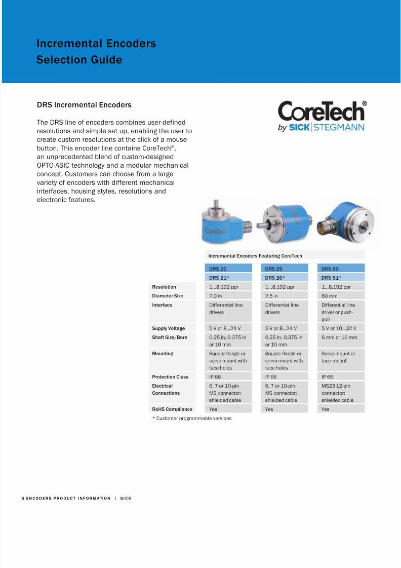
The DRS line of encoders combines user-definedresolutions and simple set up, enabling the user tocreate custom resolutions at the click of a mousebutton. This encoder line contains CoreTech ® ,an unprecedented blend of custom-designedOPTO-ASIC technology and a modular mechanicalconcept. Customers can choose from a largevariety of encoders with different mechanicalinterfaces, housing styles, resolutions and
electronic features.
DRS 20 DRS 25 DRS 60
DRS 21* DRS 26* DRS 61*
Resolution 1...8,192 ppr 1...8,192 ppr 1...8,192 ppr
Diameter Size 2.0 in 2.5 in 60 mmInterface Differential line
driversDifferential linedrivers
Differential linedriver or push-pull
Supply Voltage 5 V or 8...24 V 5 V or 8...24 V 5 V or 10...32 V
Shaft Size/Bore 0.25 in, 0.375 inor 10 mm
0.25 in, 0.375 inor 10 mm
6 mm or 10 mm
Mounting Square flange orservo mount withface holes
Square flange orservo mount withface holes
Servo mount orface mount
Protection Class IP 66 IP 66 IP 66
ElectricalConnections
6, 7 or 10-pinMS connector;shielded cable
6, 7 or 10-pinMS connector;shielded cable
MS23 12-pinconnector;shielded cable
RoHS Compliance Yes Yes Yes
* Customer programmable versions
Incremental Encoders Featuring CoreTech
Incremental EncodersSelection Guide

8/13/2019 Encoder Catalog
http://slidepdf.com/reader/full/encoder-catalog 9/24
S I C K | E N C O D E R S P RO D U C T I N FO R M AT I O N
DGS 20 DGS 25 DGS 60
Resolution 1...3,000 ppr 1...5,000 ppr 100...10,000 ppr
Diameter Size 2.0 in 2.5 in 60 mm
Interface Differential linedrivers or opencollector
Differential linedrivers or opencollector
TTL/RS 422, HTLpush-pull
Supply Voltage 5 V or 8...24 V 5 V or 8...24 V 5 V or 10...32 V
Shaft Size/Bore 0.25 in, 0.375 inor 10 mm
0.25 in, 0.375 inor 10 mm
6 mm or 10 mm
Mounting Square flange orservo mount withface holes
Square flange orservo mount withface holes
Servo mount orface mount
Protection Class IP 66 IP 66 IP 67
ElectricalConnections
6, 7 or 10-pinMS connector;
shielded cable
6, 7 or 10-pinMS connector;
shielded cable
MS23 12-pinconnector;
shielded cable
RoHS Compliance Yes Yes No
Incremental Encoders
DGS Incremental Encoders
The DGS family of heavy duty incrementalencoders are built using traditional code disktechnology. They are built to last under toughenvironmental conditions.

8/13/2019 Encoder Catalog
http://slidepdf.com/reader/full/encoder-catalog 10/24
1 0 E N C O D E R S P R O D U C T I N F O R M AT I O N | S I C K
Hub Shaft/Hollow Shaft Encoders
DGS 21/DGS 22
DGS 35/DGS 34
DFS 60 DRS 60/DRS 61CoreTech ®
DGS 65 DGS 66
Programmable Programmable
Resolution 1...2,500 ppr 120...16,384 ppr 1...65,536 ppr 1...8,192 ppr 100...10,000 ppr 100...10,000 ppr
Diameter Size 2.0 in 3.5 in 60 mm 60 mm 60 mm 60 mm
Interface Differential linedriver or opencollector
Differential linedriver or opencollector
TTL/RS 422 orHTL
TTL/RS 422,HTL push-pull
TTL/RS 422 orHTL push-pull
TTL/RS 422 orHTL push-pull
Supply Voltage 5 V or 8...24 V 5 V, 5...15 V or
8...24 V
5 V or
10...32 V
5 V or
10...32 V
5 V or
10...30 V
5 V or 10...30 V
Shaft Size/Bore 0.375 or 0.5 in 1 in or 30 mmwith collets for0.5, 0.625,0.75 and0.875 in
0.375 or 0.5 inor 10, 12, 14and 15 mm
15 mm hubshaft or 14 mmhollow shaftwith collets for6, 8, 10 or 12mm and 0.25,0.375 or 0.5 in
15 mm hubshaft withcollets for 6, 8,10 and 12 mm
15 mm hubshaft withcollets for 6,8, 10 and 12mm; hollowshaft with 6, 8,10, 12, 14 and15 mm or0.375 or 0.5 in
Mounting Integral flexmount
Tether arm oranti-rotationalpin
Integral flexmount
Integral flexmount
Compressionshaft withservo mount
Integral flexmount
Protection Class IP 50 IP 66 IP 65 IP 66 IP 65 IP 65ElectricalConnections
Shielded cable 10-pin MSconnector;shielded cable
MS23 or M12connectors;shielded cable
MS23 12-pinconnector;shielded cable
MS23 12-pinconnector;shielded cable
Shielded cable
CustomerProgrammability
N/A N/A Pulses perrevolution, zeroset function& electricalinterface
Pulses perrevolution andzero pulse(availableonly on theDRS 61)
N/A N/A
ROHS Compliance Yes Yes Yes No No No
Incremental EncodersSelection Guide
Hub Shaft/Hollow Shaft Incremental Encoders

8/13/2019 Encoder Catalog
http://slidepdf.com/reader/full/encoder-catalog 11/24
S I C K | E N C O D E R S PR O D U C T I N FO R M AT I O N
LD 20 DKS 40 HD 32 HD 52 DKV 60Measuring Wheel
Resolution 10...2,500 ppr 1...1,024 ppr 10...2,500 ppr 10...2,500 ppr 1...2048 ppr
Diameter Size 2.0 in 40 mm 3.25 in cube 3.25 in x 3.25 in x5.7 in long
60 mm
Interface Differential linedriver or opencollector
TTL/RS 422, HTLpush-pull or opencollector
Differential linedriver or opencollector
Differential linedriver or opencollector
TTL/RS 422, HTLpush-pull
Supply Voltage 5 V or 8...24 V 5 V or 10...30 V 5 V or 8...24 V 5 V or 8...24 V 5 V or 10...30 V
Shaft Size/Bore 0.25 in 8 mm 0.375 in single ordouble ended
0.375 in or0.625 in
N/A
Mounting Face mount Face mountflange, servoflange
Foot mount orface mount
Face mount Wheeled encoder
Protection Class IP 50 IP 64 IP 65 IP 66 IP65
ElectricalConnections
Shielded cable Shielded cable 6 or 10-pin MSconnector
7 or 14-pin MSconnector
Shielded cable
ROHS Compliance Yes No Yes Yes No
Special Purpose EncodersLight Duty Shaft Encoders
Light Duty and Special PurposeIncremental Encoders
8/13/2019 Encoder Catalog
http://slidepdf.com/reader/full/encoder-catalog 12/24
1 2 E N C O D E R S P R O D U C T I N F O R M AT I O N | S I C K
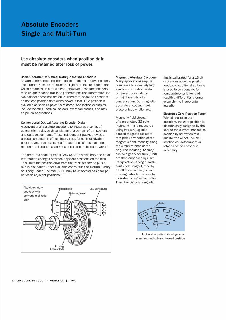
Photodetector
Stationary mask
LED Light source
RotatingEncoder Disk
Absolute rotaryencoder withconventional codedisk.
Conventional Optical Absolute Encoder DisksA conventional absolute encoder disk features a series ofconcentric tracks, each consisting of a pattern of transparentand opaque segments. These independent tracks provide aunique combination of absolute values for each resolvableposition. One track is needed for each “bit” of position infor-mation that is output as either a serial or parallel data “word.” The preferred code format is Gray Code, in which only one bit ofinformation changes between adjacent positions on the disk.This limits the position error from the track sensors to plus or
minus one count. Other available codes, such as Natural Binaryor Binary Coded Decimal (BCD), may have several bits changebetween adjacent positions.
Magnetic Absolute EncodersMany applications requireresistance to extremely highshock and vibration, widetemperature variations,or high humidity withcondensation. Our magneticabsolute encoders meetthese unique challenges.
Magnetic field strengthof a proprietary 32-polemagnetic ring is measuredusing two strategicallyspaced magneto-resistorsthat pick up variation of themagnetic field intensity alongthe circumference of thering. The resulting 32 sine/cosine signals per turn (5-bit)are then enhanced by 8-bitinterpolation. A single north-south pole magnet, read bya Hall effect sensor, is usedto assign absolute values toindividual sine/cosine cycles.Thus, the 32-pole magnetic
Typical disk pattern showing radialscanning method used to read position
Position
Tracks
Use absolute encoders when position datamust be retained after loss of power.
Basic Operation of Optical Rotary Absolute EncodersAs with incremental encoders, absolute optical rotary encodersuse a rotating disk to interrupt the light path to a photodetector,which produces an output signal. However, absolute encodersread uniquely coded tracks to generate position information. Notwo adjacent positions are alike. Therefore, absolute encodersdo not lose position data when power is lost. True position isavailable as soon as power is restored. Application examplesinclude robotics, lead/ball screws, overhead cranes, and rackan pinion applications.
ring is calibrated for a 13-bitsingle-turn absolute positionfeedback. Additional softwareis used to compensate fortemperature variation andresulting differential thermalexpansion to insure dataintegrity.
Electronic Zero Position TeachWith all our absoluteencoders, the zero position iselectronically assigned by theuser to the current mechanicalposition by activation of apushbutton or set line. Nomechanical detachment orrotation of the encoder isnecessary.
Absolute EncodersSingle and Multi-Turn

8/13/2019 Encoder Catalog
http://slidepdf.com/reader/full/encoder-catalog 13/24
S I C K | E N C O D E R S PR O D U C T I N FO R M AT I O N
Serial TransmissionWe developed SSI(Synchronous Serial Interface)to offer a cost-effectivesolution for long cable runs.The encoder produces serialdata which is transmittedusing only six wires, regardlessof encoder resolution. This isideal for transmission at highspeed over long distances— up to 3000 feet. Superiornoise immunity is achievedusing differential clock anddata signals.
Single- and Multi-TurnAbsolute EncodersUse single-turn encoderswhen the full range ofmotion in the applicationoccurs within one fullrevolution (360°) of theencoder shaft. Multi-turnencoders are recommendedfor applications involvingmultiple revolutions of theencoder shaft.
In our multi-turn encoders, ahigh precision, miniaturizedgear train, with a magneton each gear stage, isused to mechanically storeposition information over asmany as 8,192 turns. Theposition of each gear stageis determined with a pair ofHall sensors. This eliminatesthe need for costly and oftenunreliable counters andbattery back up systems.Also, position changes thatoccur while the power is offare automatically tracked.
Serial to Parallel ConversionModuleThe AD-SSI-PA convertermodule can be used withour SSI absolute encoders toconvert the transmitted datafrom serial to parallel format.These devices can be used ifthe control does not directlyaccept the SSI format.
Fieldbus SystemsOur absolute encoders canalso be supplied with popularfieldbus interfaces includingDeviceNet, Profibus, andCANopen.
Advantages of Absolute Encoders
Encoder Technology
N O N - V O L AT I L EM E M O RY
Absolute encoders are non-volatile position verificationdevices. True position isnot lost if the power fails.Continuous reading ofposition is not required.
P R O T E C T I O N
In some applications, a lossof position could result indamage to the machineryor injury to the operator. Anabsolute encoder providesposition verification themoment power is appliedwithout requiring movementto a reference position.
N O I S EI M M U N I T Y
Absolute encoders determineposition by continuallyreading a coded signal. Straypulses will not accumulateand accurate position isavailable again on the nextreading.

8/13/2019 Encoder Catalog
http://slidepdf.com/reader/full/encoder-catalog 14/24
1 4 E N C O D E R S P R O D U C T I N F O R M AT I O N | S I C K
Absolute EncodersSelection Guide
ARS 20 ARS 25 ARS 60
(CoreTech) (CoreTech) (CoreTech)
Resolution 2...32,768 cpr 2...32,768 cpr 2...32,768 cpr
Diameter Size 2.0 in 2.5 in 60 mm
Interface SSI, Push-pull,Open collector,TTL
SSI, Push-pull,Open collector,TTL
SSI or parallel
Supply Voltage 10...30 V, 8...24 V,5 V
10...30 V, 8...24 V,5 V
10...32 V
Output CodeFormats
Gray, Gray Excess,Natural Binary,
Binary CodedDecimal
Gray, Gray Excess,Natural Binary,
Binary CodedDecimal
Gray, Gray Excess,Natural Binary,
Binary CodedDecimal
Bore/Shaft Sizeand Mounting
0.25 in, 0.375 in,10 mm; Squareflange, servomountwith face holes
0.25 in, 0.375 in,10 mm; Squareflange, servomountwith face holes
6 mm with servomount or 10 mmwith face mount;15 mm hub shaftor 14 mm hollowshaft with integralflex mount andcollets for 6, 8,10 or 12 mm and0.25, 0.375 or0.5 in
Protection Class IP 66 IP 66 IP 66
ElectricalConnections
17, 19 or 23-pinMS connector;MS23 12-pinconnector;shielded cable
17, 19 or 23-pinMS connector;MS23 12-pinconnector;shielded cable
MS23 12-pinconnector;shielded cable
ROHS Compliance Yes Yes No
CoreTech Single-Turn Encoders
ARS CoreTech Single-Turn Encoders
The CoreTech concept uses a minimumnumber of components to achieve maximumvariety: proprietary hybrid OPTO-ASIC technology,designed by SICK | STEGMANN, and a small, uniquedisk with a bar code track.
Absolute EncodersSelection Guide
AVA I L A B L EA C C E S S O R I E S
• Adapters• Cable assemblies• Collets• Couplings• Bus adapters• Programming tool

8/13/2019 Encoder Catalog
http://slidepdf.com/reader/full/encoder-catalog 15/24
S I C K | E N C O D E R S PR O D U C T I N FO R M AT I O N
ATM 90-A ATM 90-P ATM 60-A ATM 60-D ATM 60-C ATM 60-P
(SSI) (Profibus) (SSI) (DeviceNet) (CANopen) (Profibus)
Resolution 13 bits perturn x 8,192turns (26bit max),programmable
13 bits perturn x 8,192turns(26 bit max),programmable
13 bits perturn x 8,192turns(26 bit max),programmable
13 bits perturn x 8,192turns(26 bit max),programmable
13 bits perturn x 8,192turns(26 bit max),programmable
13 bits perturn x 8,192turns(26 bit max),programmable
Diameter Size 93 mm 93 mm 60 mm 60 mm 60 mm 60 mm
Interface SSI, RS 422 RS 485 buscoupling toProfibus DPspecifications
SSI DeviceNetspecificationrelease 2.0
CommunicationProfile DS 301V4.0; DeviceProfile DSP
406 V2.0
RS 485 buscoupling toProfibus DPspecifications
Supply Voltage 10...32 V 10...32 V 10...32 V 10...32 V 10...32 V 10...32 V
Output CodeFormats
Gray or NaturalBinary
Gray or NaturalBinary
Gray or NaturalBinary
Bore/Shaft Sizeand Mounting
12 mm, 16mm or 0.5 inhollow shaftwith anti-rotational pinmount
12 mm, 16mm or 0.5 inhollow shaftwith anti-rotational pinmount
6 mm withservo mountor 10 mm withface mount;15 mm hubshaft withintegral flexmount andcollets for 6, 8,
10 or 12 mmand 0.25,0.375 or 0.5 in
6 mm withservo mountor 10 mm withface mount;15 mm hubshaft withintegral flexmount andcollets for 6, 8,
10 or 12 mmand 0.25,0.375 or 0.5 in
6 mm withservo mountor 10 mm withface mount;15 mm hubshaft withintegral flexmount andcollets for 6, 8,
10 or 12 mmand 0.25,0.375 or 0.5 in
6 mm withservo mountor 10 mm withface mount;15 mm hubshaft withintegral flexmount andcollets for 6, 8,
10 or 12 mmand 0.25,0.375 or 0.5 in
Protection Class IP 65 IP 65 IP 67 IP 67 IP 67 IP 67
ElectricalConnections
MS23 12-pinconnector
ThreeM14 7-pinconnectors orthree PG cableglands
MS23 12-pinconnector;shielded cable
Separate busconnector withsingle or dual5-pin microconnectors, orsingle or dualPG gland
Separate busconnector withone, two orthree PG cableglands
Separate busconnector
Absolute Multi-Turn Encoders
ATM Absolute Multi-Turn Encoders

8/13/2019 Encoder Catalog
http://slidepdf.com/reader/full/encoder-catalog 16/24
1 6 E N C O D E R S P R O D U C T I N F O R M AT I O N | S I C K
L 230 Magnetic (Lincoder ®)The Lincoder system consists of a magnetic tape and sensorhead. The magnetic tape provides the scale for measuringsystems up to 40 meters long. The absolute information ismagnetized onto the tape in a 12-bit sequential code. Thisposition information is enhanced by interpolation of sine/cosine signals provided by an additional incremental track thatis magnetized on the tape. The magnetic tape is laminated ontoa ferromagnetic steel strip, which is used both as a magnetic
return path and a dimensionally stable mounting aid. Themagnetic tape is supplied with an adhesive back for mountingby the user.
A non-contact magnetic sensor with integrated electronics ismounted to the apparatus whose position is to be measured.As the sensor moves over the measuring tape, its position isoutput with a resolution as low as 1 µm over a 16 meter range,or 10 µm over a 40 meter range. Position data is output viareal-time compensated SSI (Synchronous Serial Interface),HIPERFACE, or RS 485. The Lincoder is also programmable viaRS 485, and a number of parameters such as offset, resolutionand start points can be configured by the user.
Linear Encoders and Wire-Draw SystemsUse linear encoders to measure incremental or absolute position along any axis.Linear encoders can be used in applications up to 1.7 kilometers long.
KH 53 (Pomux ®) and Advanced KH 53Long Distance Linear EncodersThis style of encoder is unique to SICK | STEGMANN and allowsabsolute measurement of up to 1.7 kilometers! The KH 53consists of two basic components: Omega Profile sectionsand the sensor head. Each Omega Profile section containsa number of powerful permanent magnets. The separationbetween each magnet is unique and never repeated. Theseunique separations build up a code over the complete
measurement path. In a working system, several OmegaProfile sections are placed end to end along the completemeasurement path. The total length of the system determinesthe number of profiles required. Each profile section is labeledwith an identification number indicating the order in which thesections should be mounted.
The sensor head moves over the Omega Profile sectionswithout contact, and produces absolute positional data. TheKH 53 allows a generous vertical tolerance of ±10 mm arounda 25 mm nominal value, and a horizontal tolerance of ±10mm around the centerline. The output is available in SSI, andProfibus. Other networks can be realized using commerciallyavailable I/O modules.
In addition, this modular system offers several benefits tothe user. If the measurement length of the system needs toincrease in the future, the user simply needs to mount the extraprofiles required. If the Omega Profile becomes damaged, onlythe damaged sections need to be replaced.
The Advanced KH 53 has 54 m or 548 m measuring lengths,a positional/mounting tolerance to ±20 mm, and an operatingtemperature of -30 to 70°C. The Advanced KH 53 has theadded advantage of requiring less installation time than thestandard KH 53.
Length Measuring Systems
8/13/2019 Encoder Catalog
http://slidepdf.com/reader/full/encoder-catalog 17/24
S I C K | E N C O D E R S PR O D U C T I N FO R M AT I O N
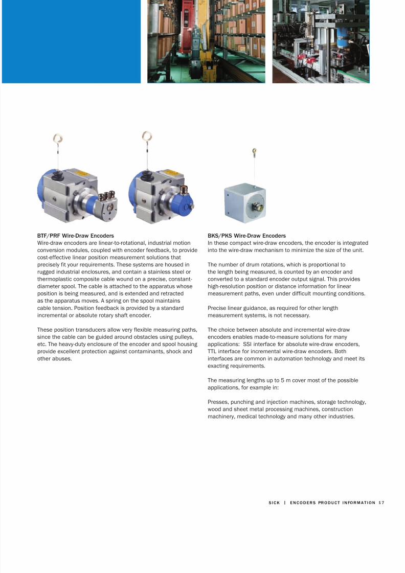
BTF/PRF Wire-Draw EncodersWire-draw encoders are linear-to-rotational, industrial motionconversion modules, coupled with encoder feedback, to providecost-effective linear position measurement solutions thatprecisely fit your requirements. These systems are housed inrugged industrial enclosures, and contain a stainless steel orthermoplastic composite cable wound on a precise, constant-diameter spool. The cable is attached to the apparatus whoseposition is being measured, and is extended and retracted
as the apparatus moves. A spring on the spool maintainscable tension. Position feedback is provided by a standardincremental or absolute rotary shaft encoder.
These position transducers allow very flexible measuring paths,since the cable can be guided around obstacles using pulleys,etc. The heavy-duty enclosure of the encoder and spool housingprovide excellent protection against contaminants, shock andother abuses.
BKS/PKS Wire-Draw EncodersIn these compact wire-draw encoders, the encoder is integratedinto the wire-draw mechanism to minimize the size of the unit.
The number of drum rotations, which is proportional tothe length being measured, is counted by an encoder andconverted to a standard encoder output signal. This provideshigh-resolution position or distance information for linearmeasurement paths, even under difficult mounting conditions.
Precise linear guidance, as required for other lengthmeasurement systems, is not necessary.
The choice between absolute and incremental wire-drawencoders enables made-to-measure solutions for manyapplications: SSI interface for absolute wire-draw encoders,TTL interface for incremental wire-draw encoders. Bothinterfaces are common in automation technology and meet itsexacting requirements.
The measuring lengths up to 5 m cover most of the possibleapplications, for example in:
Presses, punching and injection machines, storage technology,wood and sheet metal processing machines, constructionmachinery, medical technology and many other industries.

8/13/2019 Encoder Catalog
http://slidepdf.com/reader/full/encoder-catalog 18/24
1 8 E N C O D E R S P R O D U C T I N F O R M AT I O N | S I C K
L 230 Lincoder
Resolution For SSI: 1 micron withcalibrated tape,10 micron withuncalibrated tape;For Hiperface:156.25 micron
Reproducibility ± 10 micron
Measuring Length/Speed
40 m max, 6 m/sec
Interface SSI; Hiperface
Supply Voltage SSI: 10...32 V;Hiperface: 7...12 V
Measurement ScaleType
Stationary magnetictape with or withoutglue
Protection Class IP 65
Electrical Connections M23 12-pinconnector
KH 53 Pomux KH 53 Pomux
Advanced
Resolution 0.1 mm 0.1 mm
Reproducibility ± 0.3 mm ± 1.00 mm
Accuracy Within aMeasuring Element
± 1000 + ME(Tu -25°C) TK micron
± 2000 + ME(Tu -25°C) TK micron
Positional Tolerance ± 10 mm ± 20 mm
Operating Temperature -20° to 60°C -30° to 70°C
Measuring Length/Speed
1700 m max, 6.6 m/sec
54 m or 548 m, 6.6m/sec
Interface SSI, Profibus DP(07hex), Class 2
SSI, Profibus DP(07hex), Class 2
Supply Voltage 10...32 V 10...32 V
Measurement ScaleType
Stationary Omegaprofiles withembedded magnets
Stationary Omegaprofiles withembedded magnets
Protection Class IP 66 IP 66
Electrical Connections SSI: M23 12-pinconnectors;Profibus: 3 PG cableglands
SSI: M23 12-pinconnectors;Profibus: 3 PG cableglands
Linear Absolute Encoders
Linear Encoders and Wire-Draw SystemsSelection Guide
Linear Absolute Encoders
AVA I L A B L EA C C E S S O R I E S
• Cable assemblies• Magnetic tape• Couplings• Programming tool• Wire-draw mechanism
accessories

8/13/2019 Encoder Catalog
http://slidepdf.com/reader/full/encoder-catalog 19/24

8/13/2019 Encoder Catalog
http://slidepdf.com/reader/full/encoder-catalog 20/24
2 0 E N C O D E R S P R O D U C T I N F O R M AT I O N | S I C K
HIPERDRIVE ® Format Adjustment Positioning Drives
HIPERDRIVE (Highly Integrated Performance Drive) is an integrated drive system with absolute positioning, suitable for all kindsof format adjustment in machines and installations. The operations system includes a motor, gears, absolute encoder andfield bus communication capability.
Modern logistic concepts call for smaller batch sizes in many production areas, with numerous adjustments being performedduring product changeovers. The HIPERDRIVES ensure efficient, cost-effective and high-precision automation of adjustmentsto auxiliary axes. This process is normally called “format adjustment,” but in some markets, “automatic size change” is morefamiliar.
The HDA family, with a maximum torque rating of 20 Nm, and the HRA family, with a torque rating of 1 Nm to 12 Nm, are theresults of a consistent and complete integration of power transmission, brushless DC motor, absolute encoder and power
electronics into one positioning drive.
HIPERDRIVE
C O M P L E T E I N T E G R AT E D S Y S T E M
Reduced installation and commissioning costs
Low cabling requirements: 24V DC and serial datainterface only No additional external control electronics
Separate voltage supply to motor and bus logic
“Manual” adjustment without controller, using JOG button(s)
A B S O L U T E P O S I T I O N E N C O D E R
Absolute position available immediately after returnof operating voltage
Reference traverse not required
Protection of mechanical machine elements from damage
Machine settings can always be safely logged
HIPERDRIVE ADVANTAGES
H I G H H O L D I N G T O R Q U E I ND E - E N E R G I Z E D S TAT E
No additional brake components required for the HIPERDRIVE
Very secure process

8/13/2019 Encoder Catalog
http://slidepdf.com/reader/full/encoder-catalog 21/24

8/13/2019 Encoder Catalog
http://slidepdf.com/reader/full/encoder-catalog 22/24
2 2 E N C O D E R S P R O D U C T I N F O R M AT I O N | S I C K
Motor Feedback Systems(SinCos ® series STAND ALONE)*
SKS/SKM36 SRS/SRM50 SRS/SRM60
STAND ALONE STAND ALONE STAND ALONE
128 sine/cosineperiods
1,024 sine/cosineperiods
1,024 sine/cosineperiods
• Solid shaft 6 mm• Absolute position
4,096 steps perrevolution
• 4,096 revolutions can be measured(Multiturn)
• Programming of the positional value
• Electronic type label
• Solid shaft 6 or 10 mm• Absolute position
with a resolutionof 32,768 steps perrevolution
• 4,096 revolutions can be measured(Multiturn)
• Programming of the positional value
• Electronic type label
• Hollow shaft• Absolute position
with a resolutionof 32,768 steps perrevolution
• 4,096 revolutions can be measured(Multiturn)
• Programming of the positional value
• Electronic type label
# of sine/cosine periodsper revolution
128 1,024 1,024
Total number of steps Single SKS 4,096Multi SKM 16.777.216
= 4.096 x 4.096
Single SRS 32,768Multi SRM
134.217.728 =32.768 x 4.096
Single SRS 32,768Multi SRM
134.217.728 =32.768 x 4.096
Non linearity ± 120 angular seconds ± 52 angular seconds ± 45 angular seconds
Working speed 6,000 min -1 6,000 min -1 6,000 min -1
Working temp range -20 ... 100 ºC -20 ... 85 ºC 20 ... 115 ºC
Operating voltage range 7 ... 12 V 7 ... 12 V 7 ... 12 V
Type ID Single SKS = 32hMulti SKM = 37h
Single SRS = 22hMulti SRM = 27h
Single SRS = 22hMulti SRM = 27h
Motor Feedback Systems
Today’s high-performance digital servo drive systems requireabsolute feedback for position control and high-resolutionincremental feedback for speed control. Both are available.
Our SinCos family of servo motor feedback devices combinescommunication, speed regulation, and position information ina single device.
The Innovative HIPERFACE ® Interface
*Only stand-alone versions of the motor feedback encoders are available. For other versions, please contact our team of application engineers.

8/13/2019 Encoder Catalog
http://slidepdf.com/reader/full/encoder-catalog 23/24
S I C K | E N C O D E R S PR O D U C T I N FO R M AT I O N
Encoder Accessories andHIPERFACE ® Adapters
We sell helvetical curvedbeam, bellows, and springdisc couplings for all ourencoders.
We provide collets and shaftinserts of various sizes forour blind and through hollowshaft encoders.
C A B L E S A N D C A B L EC O N N E C T O R S
We manufacture our owncables with lead times of6-8 days. We provide M12,M14, M23, MS6, MS7 andMS10 cable connectors withthe number of pins you need,as well as mating cables andcable/connector assembliesof various lengths.
C O U P L I N G S S H A F TI N S E RT S / C O L L E T S
O T H E RA C C E S S O R I E S
We also offer mechanicaladapters and hardware, SSIparallel adapter modules,measuring wheels, wire-draw encoder accessories,as well as programmingtools and software for ourprogrammable encoders.
Encoder Accessories
The HIPERFACE interface adapter modules allow users to connect single-turn or multi-turn encoders that have the HIPERFACE interfaceto systems using other communication protocols, opening up a variety of application options in all areas of automation technology.
Motor Feedback Meets Factory Automation
In conjunction with a HIPERFACE interface adapter module, encoders can be usedin a broad range of applications in automation technology. For example where:
• High encoder resolutions are necessary — up to 262,000 counts per turn can be generated easily in the interface adapter via interpolation of the HIPERFACEencoder signals.
• Space is very limited.• Environmental conditions such as dirt, temperature, shock and/or vibration
must be isolated from the electronics.
• Customer-specific encoder flange and housing options are required, which must be realized quickly and at a low cost.
At the output of the interface adapter modules, SSI, Profibus, DeviceNet andCANopen are available, using standard M12 connectors. These interfaces fulfillthe high requirements of automation technology. Further, the diverse range ofpossible combinations of interface adapter modules and encoders provides ahigh level of flexibility, coupled with low part replacement and stocking costs.
HIPERFACEInterfaceAdapterModule
Out
In
ToPLC
Encoder withHIPERFACEInterface
PROFIBUS
SSI Interface
DeviceNet
CANopen

8/13/2019 Encoder Catalog
http://slidepdf.com/reader/full/encoder-catalog 24/24
7 0 2 8 2 6 7
. 0 8 1 1
• S
u b j e c t t o c h a n g e w
i t h o u
t n o t i c e
Worldwide presence withsubsidiaries in the followingcountries:
AustraliaAustriaBelgium/Luxembourg
BrazilChinaCzech RepublicDenmarkFinlandFranceGermanyGreat BritainIndiaItalyJapanNetherlandsNorwayPoland
Republic of KoreaRepublic of SloveniaRussiaSingapore
SpainSwedenSwitzerland
TaiwanTurkeyUSA/Canada/Mexico
Please find the detailedaddresses and morerepresentatives and agenciesin all major industrial nations atwww.sick.com
SICK, Inc. | Minneapolis, MN | USA | phone 800.325.7425 | www.sickusa.com
S A F E T Y S Y S T E M S
Comprehensive safeguarding ofboth personnel and machinery. Asspecialists in safety technology,SICK develops and manufacturespioneering products for providingprotection in hazardous zones,dangerous locations and forsafeguarding access points. Byproviding services, whichencompass all aspects of machinesafety and security, SICK issetting new standards in SafetyTechnology.
A U TO M AT I CI D E N T I F I C AT I O N
Whether the tasks involveidentification, handling,classification or volumemeasurement, innovativeautomatic identification systemsand laser measurement systemsfunction extremely reliably, evenunder rapid cycle times. Theyconform to the latest standardsand can be simply and quicklyintegrated in all industrialenvironments and externalapplications.
A N A LY Z E R S A N D P R O C E S SI N S T R U M E N TAT I O N
SICK MAIHAK offers solutions forsystem control, maintainingsetpoints, optimizing processcontrol and monitoring the flow ofmaterials. Our analysis andprocess measurement productsare setting the standards forthese applications in terms oftechnology and quality.
I N D U S T R I A L S E N S O R S
Our complete range of sensorsprovides solutions for anyapplication in the field ofautomation. Even under ruggedambient conditions, objects arereliably detected, counted andpositioned in respect to theirform, location and surface finish,as well as their distances.
R A N G E O F E X P E R T I S E