
EMU STREET, WALLAROO, PUMP STATION A Part 2 ... 2014 EMU STREET, WALLAROO, PUMP STATION A Rising...
72
August 2014 EMU STREET, WALLAROO, PUMP STATION A Rising Main, Gravity Drains, Pump Station Part 2: Technical Specification Part A – Preliminaries and Special Conditions Part B – Technical Specification Contract No 130549.C02_Wallaroo PS A
Transcript of EMU STREET, WALLAROO, PUMP STATION A Part 2 ... 2014 EMU STREET, WALLAROO, PUMP STATION A Rising...

August 2014
EMU STREET, WALLAROO, PUMP STATION A
Rising Main, Gravity Drains, Pump Station
Part 2: Technical Specification
Part A – Preliminaries and Special Conditions Part B – Technical Specification Contract No 130549.C02_Wallaroo PS A
130549 August 2014
Emu Street, Wallaroo, Pump Station A Technical Specification
i
CONTENTS
A1. ORGANISATION ...........................................................................................................................1
A2. SCOPE OF CONTRACT & EXTENT OF WORKS .......................................................................1
A3. DRAWINGS ASSOCIATED WITH THE WORKS .........................................................................4
A4. ORDER OF PRECEDENCE OF DOCUMENTS ............................................................................4
A5. CONTRACT PROGRAM AND IMPLICATIONS ...........................................................................4 A5.1 Contract Program ............................................................................................................. 4 A5.2 Use of Contract Program as a Reference ........................................................................ 5 A5.3 Sequencing of Works ....................................................................................................... 5
A6. CONTRACT BUDGET AND IMPLICATIONS ...............................................................................5 A6.1 Status of Contract Budget ................................................................................................ 5
A7. PROVISION OF SECURITY ..........................................................................................................5
A8. GOODS AND SERVICES TAX .....................................................................................................6
A9. STATUTORY AND OTHER REQUIREMENTS ............................................................................6 A9.1 General ............................................................................................................................. 6 A9.2 Industrial Awards .............................................................................................................. 6 A9.3 Workers Compensation .................................................................................................... 6 A9.4 Health, Safety and Welfare .............................................................................................. 6 A9.5 Construction Industry Training Board ............................................................................... 7
A10. SITE OF THE WORKS ..................................................................................................................7 A10.1 Site of Works .................................................................................................................... 7 A10.2 Traffic Routes ................................................................................................................... 7 A10.3 Construction Restrictions ................................................................................................. 7
A11. SITE ORGANISATION, MANAGEMENT AND CONTROL ..........................................................8 A11.1 Site Organisation .............................................................................................................. 8 A11.2 Site Management ............................................................................................................. 8 A11.3 Site Meetings .................................................................................................................... 8 A11.4 Working Hours .................................................................................................................. 8 A11.5 Supervision and Inspection .............................................................................................. 9 A11.6 Assistance for Measuring and Checking .......................................................................... 9 A11.7 Environmental Control and Nuisance ............................................................................... 9
A12. SITE RECORDS AND DAILY DIARIES ..................................................................................... 10
A13. TEMPORARY BUILDINGS, AMENITIES AND SERVICES ...................................................... 11 A13.1 Site Offices and Storage Sheds ..................................................................................... 11 A13.2 Amenities ........................................................................................................................ 11 A13.3 Water for the Works ....................................................................................................... 11 A13.4 Electricity for the Works.................................................................................................. 11
A14. WORK ON AND ADJACENT TO PRIVATE PROPERTY ......................................................... 12 A14.1 Community Goodwill ...................................................................................................... 12 A14.2 Notice to all Residents.................................................................................................... 12 A14.3 Temporary Security of Property ..................................................................................... 12 A14.4 Progressive Cleaning Up ............................................................................................... 12
130549 August 2014
Emu Street, Wallaroo, Pump Station A Technical Specification
ii
A15. PROTECTION OF PROPERTY, MATERIALS AND FINISHED WORKS ................................. 12 A15.1 Protection of Property..................................................................................................... 12 A15.2 Preservation of Flora in Streets, Parks, Public Places and Private Property................. 12 A15.3 Surface Waters ............................................................................................................... 13 A15.4 Protection of Materials and Finishes .............................................................................. 13
A16. DILAPIDATION RECORDS ....................................................................................................... 13
A17. DAMAGE AND MAKING GOOD ................................................................................................ 14 A17.1 General ........................................................................................................................... 14 A17.2 Road and Footpath Reinstatement ................................................................................ 14 A17.3 Release of Obligation ..................................................................................................... 14
A18. UNDERGROUND AND OTHER SERVICES.............................................................................. 14 A18.1 Underground and Other Services .................................................................................. 14 A18.2 Special Conditions Relating to Work Adjacent Services ................................................ 15 A18.3 Alteration to Public Utilities ............................................................................................. 15 A18.4 Undocumented Existing Underground Services ............................................................ 16
A19. TRAFFIC CONTROL AND SAFETY .......................................................................................... 16 A19.1 Traffic Control ................................................................................................................. 16 A19.2 Public Safety .................................................................................................................. 17 A19.3 Unsafe Working Conditions ............................................................................................ 17
A20. LEVELS, SETTING OUT AND SURVEY MARKS ..................................................................... 17
A21. INSPECTION .............................................................................................................................. 18 A21.1 Liability in Calling for Inspection ..................................................................................... 18 A21.2 Inspection Before Concealment ..................................................................................... 18
A22. TESTING ..................................................................................................................................... 18
A23. LIABILITIES IN THE CASE OF MISTAKES MADE BY THE CONTRACTOR ......................... 19
A24. STANDARDS .............................................................................................................................. 19
A25. PLANT AND EQUIPMENT ......................................................................................................... 19 A25.1 Constructional Plant ....................................................................................................... 19 A25.2 Equipment, Gear, Tools, etc .......................................................................................... 19 A25.3 Idle Plant, Equipment, Gear, etc .................................................................................... 19
A26. MATERIALS AND WORKMANSHIP ......................................................................................... 20 A26.1 General ........................................................................................................................... 20 A26.2 Sealed Containers .......................................................................................................... 20
A27. MANUFACTURER’S DIRECTIONS ........................................................................................... 20
A28. PROPRIETARY ITEMS .............................................................................................................. 20
A29. SALVAGED ITEMS .................................................................................................................... 20
A30. UNOBTAINABLE MATERIALS – SUBSTITUTION .................................................................. 21
A31. PROVISIONAL COST ITEMS (TENDERED RATES) ................................................................ 21
A32. HANDOVER ................................................................................................................................ 21 A32.1 Certificates and Guarantees .......................................................................................... 21 A32.2 Appointed Person ........................................................................................................... 21

130549 August 2014
Emu Street, Wallaroo, Pump Station A Technical Specification
iii
B1. MATERIALS AND EQUIPMENT ................................................................................................ 22 B1.1 GENERAL ...................................................................................................................... 22 B1.2 PIPES, FITTINGS AND JOINTING MATERIALS .......................................................... 22 B1.3 VALVES ......................................................................................................................... 24 B1.4 PIPE BEDDING .............................................................................................................. 24 B1.5 BACKFILLING ................................................................................................................ 25 B1.6 PAVEMENT MATERIALS .............................................................................................. 25 B1.7 CONCRETE MATERIALS .............................................................................................. 26 B1.8 FERROUS COMPONENTS ........................................................................................... 28 B1.9 FENCING ....................................................................................................................... 28
B2. CONCRETE CONSTRUCTION STANDARDS .......................................................................... 29 B2.1 SCOPE ........................................................................................................................... 29 B2.2 MIXING ........................................................................................................................... 29 B2.3 PLACING ........................................................................................................................ 31 B2.4 CURING ......................................................................................................................... 32 B2.5 PROTECTION ................................................................................................................ 32 B2.6 PRECAST UNITS ........................................................................................................... 32
B3. EXCAVATION, BACKFILL AND REINSTATEMENT ................................................................ 33 B3.1 NOTICE BEFORE COMMENCEMENT OF WORKS .................................................... 33 B3.2 SITE PREPARATION..................................................................................................... 33 B3.3 EXCAVATION ................................................................................................................ 33 B3.4 DEWATERING ............................................................................................................... 36 B3.5 ROCK EXCAVATION - PROVISIONAL SUM ................................................................ 37 B3.6 SHORING ....................................................................................................................... 39 B3.7 BACKFILL ...................................................................................................................... 39 B3.8 REINSTATEMENT OF PROPERTY, PAVEMENTS AND FOOTWAYS ....................... 41
B4. GRAVITY DRAINS, RISING MAINS AND MAINTENANCE HOLES ........................................ 44 B4.1 INSTALLATION OF DRAINS, RISING MAINS AND PROPERTY CONNECTIONS ..... 44 B4.2 MAINTENANCE SHAFTS .............................................................................................. 46 B4.3 FLUSHING POINTS ....................................................................................................... 47 B4.4 PROPERTY CONNECTIONS ........................................................................................ 47 B4.5 MAINTENANCE HOLES ................................................................................................ 48 B4.6 TESTING OF GRAVITY DRAINS .................................................................................. 49 B4.7 TESTING OF RISING MAINS ........................................................................................ 50 B4.8 DRAINS OR RISING MAINS UNDER CREEK BED ...................................................... 50 B4.9 THRUST BLOCKS ON RISING MAINS ......................................................................... 50 B4.10 LOCATION MARKER POSTS FOR RISING MAINS ..................................................... 50 B4.11 VALVES ON RISING MAINS ......................................................................................... 51 B4.12 GALVANISED STEEL PIPE ........................................................................................... 51 B4.13 FLUSHING OF GRAVITY DRAINS ................................................................................ 51 B4.14 FLUSHING OF RISING MAINS ..................................................................................... 52
B5. PUMP STATIONS ....................................................................................................................... 52 B5.1 EXCAVATION FOR AND CONSTRUCTION OF PUMP STATION/S ........................... 52 B5.2 SEALING OF PUMP SUMPS ........................................................................................ 53 B5.3 TESTING OF PUMP SUMPS ........................................................................................ 53 B5.4 BACKFILL AROUND PUMP SUMPS ............................................................................ 53 B5.5 VALVE INSPECTION BOX ............................................................................................ 53 B5.6 VENTING OF PUMPING SUMPS .................................................................................. 54 B5.7 INSTALLATION AND OPERATION OF PUMPS AND EQUIPMENT ............................ 54 B5.8 PUMPS AND EQUIPMENT ........................................................................................... 54 B5.9 CONTROL SWITCHBOARD AND SWITCHGEAR ....................................................... 55 B5.10 PUMP OPERATION ....................................................................................................... 61 B5.11 METER CABINET, SWITCHBOARD AND PUMP CONTROL BOARD ........................ 62 B5.12 SUPPLY OF ELECTRICITY AND TELECOMMUNICATIONS EXCHANGE LINE ........ 62
130549 August 2014
Emu Street, Wallaroo, Pump Station A Technical Specification
iv
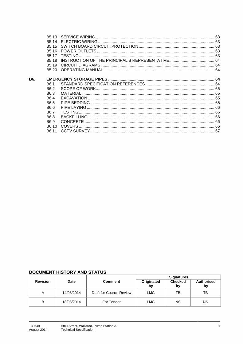
B5.13 SERVICE WIRING ......................................................................................................... 63 B5.14 ELECTRIC WIRING ....................................................................................................... 63 B5.15 SWITCH BOARD CIRCUIT PROTECTION ................................................................... 63 B5.16 POWER OUTLETS ........................................................................................................ 63 B5.17 TESTING ........................................................................................................................ 63 B5.18 INSTRUCTION OF THE PRINCIPAL’S REPRESENTATIVE........................................ 64 B5.19 CIRCUIT DIAGRAMS..................................................................................................... 64 B5.20 OPERATING MANUAL .................................................................................................. 64
B6. EMERGENCY STORAGE PIPES .............................................................................................. 64 B6.1 STANDARD SPECIFICATION REFERENCES ............................................................. 64 B6.2 SCOPE OF WORK ......................................................................................................... 65 B6.3 MATERIAL ..................................................................................................................... 65 B6.4 EXCAVATION ................................................................................................................ 65 B6.5 PIPE BEDDING .............................................................................................................. 65 B6.6 PIPE LAYING ................................................................................................................. 66 B6.7 TESTING ........................................................................................................................ 66 B6.8 BACKFILLING ................................................................................................................ 66 B6.9 CONCRETE ................................................................................................................... 66 B6.10 COVERS ........................................................................................................................ 66 B6.11 CCTV SURVEY .............................................................................................................. 67
DOCUMENT HISTORY AND STATUS
Revision Date Comment
Signatures
Originated by
Checked by
Authorised by
A 14/08/2014 Draft for Council Review LMC TB TB
B 18/08/2014 For Tender LMC NS NS

130549 August 2014
Emu Street, Wallaroo, Pump Station A Technical Specification
1
Part A
PRELIMINARIES AND SPECIAL CONDITIONS
A1. ORGANISATION
Unless otherwise notified from time to time the following key personnel are concerned with the carriage of the project. Principal's Representative: Wade Della Torre Designer's Representative: Nathan Silby Superintendent: District Council of Copper Coast Superintendent's Representative: Wade Della Torre Address for all Communications: 51 Taylor St Kadina, SA 5554 Telephone: (08) 8828 1200 Facsimile: (08) 8821 2736 The Contractor's attention is drawn to the fact that the foregoing information does not authorise the Contractor, in normal circumstances, to deal other than with the Superintendent as required by the General Conditions of Contract, but note that where the general conditions provide, notices to the Principal should be sent to the Principal's Representative.
A2. SCOPE OF CONTRACT & EXTENT OF WORKS
The District Council of the Copper Coast requires the upgrade of Pump Station 1 at Emu Street in Wallaroo. The project includes the construction and commissioning of the new pump station, including connections to the existing gravity drains and rising main, and the demolition of the existing pump station following the commissioning of the new pump station. The works to be completed are detailed in the technical specification. The following list indicates the main elements of the Works sufficient to ensure that the Contractor is aware of the scope of the Contract. It does not detail duties, actions or items of supply on minor works which are self-evident or inherent to the satisfactory completion of the scheme as described in the tender documents.
Preliminaries: This includes:
• Site establishment - The transportation of all personnel, plant and materials to and from the site and the provision of temporary site accommodation. Also includes the provision of all personnel, facilities and amenities for the administration of the works of the scheme including temporary connections to Telstra/NBN, SA Power Networks and SA Water.
• Site security – The provision for all site security.
• Quality control and quality assurance – The provision for quality control and assurance, including line flushing, hydraulic testing, air testing and compaction testing of trench backfill, as well as environmental controls and traffic management.

130549 August 2014
Emu Street, Wallaroo, Pump Station A Technical Specification
2
• Setting out of the works – The provision of all setting out of the works, including locating services, survey, etc. Also includes consultation with SA Water regarding work around existing services.
• Documentation – The provision of as constructed drawings, Operations Manuals and dilapidation reports (as per Section A16).
• Administration – The provision for Council training and site meetings, and obtaining all licenses and payment of fees when required for conduct of the Works and compliance with all regulations relating to the Works.
• Inspections – The provision for PC inspections and End of Defects inspections.
Gravity Drains Prior to construction of the pump station, the Contractor must:
• Provide details of the proposed hook up between the new and existing gravity drains.
• Confirm the location, size and material of the existing gravity drains.
• Confirm the layout of the new gravity drain. As part of the new construction, and once a detailed plan has been approved, the Contractor must supply and install the gravity mains and associated flushing points and manholes as shown in the drawings. Pump Station Construct one new pump station as shown in the Drawings. Pumps are to be Flygt or equivalent approved. Should the Contractor offer an alternative pump, the following information should be provided:
• The cost of any modifications to Council’s standard control panel must be included in the cost of the pump supply.
• The Superintendent will request the warranty for all pump suppliers as part of the submission.
• The alternative pump must be integrated into Council’s standard pump well fittings such that replacement of the pump if necessary can be easily interchangeable with Council’s existing pump network. Any flange and/or fitting modifications must form part of the alternative pump submission.
• Costs to integrate the proposal into Council’s long term SCADA network must be considered as part of the submission.
Alternative pumps may or may not be accepted. Emergency Storage Pipes The emergency storage pipes should be constructed using 1.2m diameter rubber ring joint (RRJ) reinforced concrete pipes. The RRJ pipes should be constructed in accordance with the following criteria and drawings:
• The minimum class of pipe is to be Class 4.
• The structure is to be designed to all relevant codes and practices, including AS3735 and AS3600.
• The chamber shall be designed for trafficable loads of at least W80 to AS5100. The design shall comply with all requirements set out in AS5100.
• The minimum exposure class of the internal concrete surface is to be D to AS3735.
• The concrete strength is to be S40 to Water Services Association concrete special class WSA 114.
• The structure is to be tested in accordance with AS3735.
• The design shall include provisions to prevent uplift of the structure during external flooding.

130549 August 2014
Emu Street, Wallaroo, Pump Station A Technical Specification
3
The Contractor may provide alternative cost for emergency storage system such as Humes sewer storage tanks or equivalent. Storage capacity should be at least 138 kL.
Rising Main Prior to construction of the pump station, the Contractor must:
• Provide details of the proposed hook up between the new and existing rising main.
• Confirm the location, size and material of the existing rising main.
• Confirm the layout of the new rising main. As part of the new construction, and once a detailed plan has been approved, the Contractor must supply and install a rising main of the same material as that of the existing rising main.
Civil Works: Carry out all site works, locations and/or protection of existing services, de-watering, bunding, water supply, electricity supply, drainage and hardstands as shown on the Drawings and as specified herein.
Backfilling and maintaining unsealed excavations, including sweeping, topping up with road base and compaction to maintain roads in a sage condition prior to sealing works commencing.
The Contractor is responsible for pavement reinstatement. Reinstatement shall be like for like, and the Contractor is responsible for the level control prior to sealing. Ancillary Works: Carry out any traffic control, noise control, vibration monitoring and/or liaison with the community, as specified herein or as required by applicable Australian Standards. Demolition Works: The existing pump station is to be demolished following the commission of the new pump station. All material shall be disposed of by the contractor and the site should be made good to match the surrounds. The demolition should be in accordance with the following, noting that this only sets out the scope associated with civil works only.
• All work shall be managed to ensure the safety of all stakeholders including pedestrians, road users and site personnel in accordance with all relevant South Australian legislation, acts, policies, guidelines and codes of practice.
• Work shall be carried out with all due care and sensitivity to prevent nuisance and risks to the environment and the public at large.
• All work shall be carried out in accordance with the South Australian Environment Protection Act 1993, and all applicable policies including noise and dust abatement procedures.
• All work around trees that are required to remain shall be undertaken with care and sensitivity. Particular care shall be taken to avoid damage to root systems and limbs. Tree protection during construction is to be undertaken in accordance with AS4970 - Protection of Trees on Development Sites - 2009.
• All services shall be located on site and any removals and relocations coordinated with service authorities.
• All remaining site features impacted or damaged by works shall be made good and/or replaced depending upon damage sustained.
• Removal and/or management of contaminated material are not covered with this documentation scope.
• The work outlined in this plan is not exhaustive. It shall be confirmed on site prior to removal.
The Contract for the Works is a lump sum tender, which includes Provisional Cost Sums as listed in the Tender Schedules.

130549 August 2014
Emu Street, Wallaroo, Pump Station A Technical Specification
4
The items described above are only provided to assist the Contractor in understanding the order of magnitude of the works. They shall not be used as a basis for tender. Quantities to be used by the Contractor and the nature of the prevailing site conditions adopted in preparing the tender are to be determined by the Contractor from the Drawings and documents referred to herein and a site inspection. The Contractor shall provide details of the proposed pump station as based on the Drawings and the Specification detailed herein. The Contractor shall allow for ancillary and site works as required to suit his plant to the minimum standards as shown on the Drawings and as specified herein. A complete description and plans of proposed plant and equipment is to be included in the Tender Schedules, and any shortcomings, limitations or differences of the submitted tender to the requirements specified or as shown on the Drawings are to be highlighted at the time of tender. The Contractor may be asked to detail additional information on their proposed plant or to consider modifications or alterations to their proposal at the time of tender. When the Specification and Drawings do not contain any mention of minor parts of work which, in the opinion of the Superintendent, are reasonably and obviously necessary for the satisfactory completion of the Contract Works, such parts shall be supplied and installed by the Contractor without any extra charge.
A3. DRAWINGS ASSOCIATED WITH THE WORKS
The Drawings associated with the Contract Works are included as Appendix A and listed below:
• 130549-1_Document Transmittal
• WAD130549-PSA-01-C
• WAD130549-PSA-02-D
• WAD130549-PSA-03-C
• WAD130549-PSA-04-C
• WAD130549-PSA-05-C
A4. ORDER OF PRECEDENCE OF DOCUMENTS
In the event that there is any conflict, contradiction or ambiguity between any documents which form part of this Agreement, the order of precedence specified in Clause 6.1 of the General Conditions of Contract shall be applied in order to resolve any such conflict, contradiction or ambiguity.
A5. CONTRACT PROGRAM AND IMPLICATIONS
The following clauses are in addition to Clause 36 of the General Conditions of Contract.
A5.1 Contract Program The Contractor shall prepare a detailed construction program in the form of a bar chart (or critical path if thought necessary). The Contract Program shall have key dates as set out in the Annexure to the General Conditions of Contract, and as may be from time to time amended in accordance with the General Conditions of Contract.

130549 August 2014
Emu Street, Wallaroo, Pump Station A Technical Specification
5
A5.2 Use of Contract Program as a Reference The program shall be displayed at site in the Contractor's Office. The Contractor shall keep himself informed of the daily progress on all parts of the Works and of their interactive effect on the commencement of any section of the Works, and correlate that information with the approved program, keeping a record of actual progress on the displayed program. Such progress record shall be of a form approved by the Superintendent. If the Superintendent considers it necessary in order to co-ordinate the work of other independent activities on the site, the Superintendent may give such directions as he deems appropriate regarding any deviation from the approved program in accordance with Clause 36.2 of the General Conditions of Contract.
A5.3 Sequencing of Works
As a priority, the Contractor shall first confirm the location of the existing rising main and gravity drains, and then provide a plan of the hook ups into these mains. This shall be conducted prior to commencement of construction. The program of works shall be submitted to the Superintendent for approval prior to work commencing on site.
A6. CONTRACT BUDGET AND IMPLICATIONS A6.1 Status of Contract Budget
The Tendered Sum for completion of the works including the Provisional Cost Items and any allowance for Contingencies shall form the Contract Budget which shall be contractually binding in the following ways:
a. It shall be the means by which the financial status of the Works and the costs and
expenditure of the Scheme may be judged.
b. The Contract Budget cannot be exceeded without the Principal's approval. Therefore, if there are indications that the Contract Budget is to be exceeded, the Superintendent may issue a variation or variations as stated in (c) hereof.
c. If there is evidence that legitimate Contract variations and prolongation costs are being
incurred, and that no reasonable action by the Contractor or Superintendent can be taken to avoid cost overruns, then the Superintendent may:
i. reduce the extent of the Works by variation as he deems necessary to keep the
Scheme within the Budgeted funds; or ii. seek approval from the Principal to increase the Contract Sum by the relevant
amount.
A7. PROVISION OF SECURITY
Pursuant to the General Conditions of Contract, security shall be provided as two equal bank guarantees which shall be reduced by one half when Practical Completion is awarded.
130549 August 2014
Emu Street, Wallaroo, Pump Station A Technical Specification
6
A8. GOODS AND SERVICES TAX
All materials and services supplied under the Contract are to be inclusive of Goods and Services Tax (GST). The Contractor shall quote GST inclusive prices at the time of tendering and for all variations. The Contractor shall clearly state the amount of GST on tax invoices presented with each progress claim.
A9. STATUTORY AND OTHER REQUIREMENTS A9.1 General
The Contractor shall comply with all relevant requirements in accordance with the provisions of the General Conditions of Contract.
A9.2 Industrial Awards
The employment of labour by the Contractor shall be in accordance with the appropriate provisions of relevant industrial awards.
A9.3 Workers Compensation
The Contractor shall be registered as an employer with WorkCover pursuant to the Worker's Rehabilitation and Compensation Act.
No part of the Contract Works shall be undertaken by the Contractor, or any subcontractors, unless the Contractor and the subcontractors are so registered.
The Contractor shall produce the appropriate Certificate of Registration, for inspection by the Superintendent, prior to the undertaking of any part of the Contract Works.
A9.4 Health, Safety and Welfare
a. The Contractor shall comply with all requirements of the Occupational Health, Safety and Welfare Act, 1986 as applied to the persons employed and the type of work executed on the Contract and shall ensure that his employees also comply with such requirements.
b. The Contractor shall comply with the requirements of the Local Government Works
Contract (Model Policy) “Contracting Occupational Health, Safety and Welfare Policy” dated September, 1995.
Where there is any conflict between the provisions of this Clause and the Model Policy, the Model Policy shall take precedence.
c. The Contractor acknowledges that the Principal has obligations under the Occupational Health, Safety and Welfare Act and has the right/obligation to ensure that the Contractor is complying with the Act.
d. The Contractor shall acknowledge in writing that he has been provided with, read and
understands the Occupational Health, Safety and Welfare policies and statements of the Principal and undertakes to ensure they are brought to the attention of his employees.
e. The Contractor shall ensure compliance with any advice and/or direction issued by the
Council and/or its agent.
f. The Contractor shall provide, for themselves and their employees, all necessary protective equipment and enforce the correct usage and maintenance of any such equipment.
130549 August 2014
Emu Street, Wallaroo, Pump Station A Technical Specification
7
g. The Contractor shall exercise due skill, care and expertise in the performance of the
Contract. A9.5 Construction Industry Training Board
The Contractor shall be registered with the Construction Industry Training Board (Civil Construction Industry Sector).
The Contractor shall register the project with the Construction Industry Training Board prior to the commencement of the works on site, based on the contract price. Evidence of registration shall be submitted to the Superintendent prior to the first progress claim. The Contractor shall allow for the CITB levy in the total contract price – no separate payment will be made for this item. The appropriate training levy, based on the actual total contract payments made to the Contractor (including variations), shall be paid by the Contractor at the completion of the works on the site. Evidence of payment shall be submitted to the Superintendent prior to issue of the Certificate of Practical Completion.
A10. SITE OF THE WORKS A10.1 Site of Works
The site of the Works is the whole of the land space within road reserves and easements required for the construction of the Works, subject to the following conditions and as defined by the Drawings, which precincts shall include areas and access ways as from time to time in writing agreed with or instructed by the Superintendent.
The Contractor may only use, for access or any other purpose, any remaining private property with the express consent of the property owner. The Contractor shall be fully liable for any cost or agreement made in respect to the use of private property for any part of the Works with the owner.
A10.2 Traffic Routes
To all reasonable extents, construction traffic is to be limited to those streets immediately adjoining current works locations. Traffic management and signage in accordance with Australian Standards shall be erected and maintained throughout the duration of the works. Advanced notice signs shall be erected as directed by the Superintendent at key locations within a timeframe following Contract award to be nominated.
A10.3 Construction Restrictions
No construction activities are to take place from Thursday 2nd
April to Tuesday 7th April 2015
(inclusive) for the Easter holiday period. There are no other specific construction restrictions placed on the Contractor’s activities, apart from general requirements detailed elsewhere in this Specification.

130549 August 2014
Emu Street, Wallaroo, Pump Station A Technical Specification
8
A11. SITE ORGANISATION, MANAGEMENT AND CONTROL A11.1 Site Organisation
Except as otherwise provided in the Contract, delivery of any materials for the purpose of the works, space for storage of materials and for building sheds, offices and workshops will only be permitted as provided for herein and as arranged and approved by the Superintendent. When flammable or combustible material is to be stored or used, the Contractor shall adhere strictly to any statutory requirements and any instruction given by the Superintendent. No new tracks shall be formed, existing tracks altered, camps erected, trees or shrubs removed, fences cut, water, sewerage or power lines cut or any other such thing done without the prior approval of the Superintendent. Under no circumstances shall fires be lit without the prior approval of the Superintendent.
A11.2 Site Management
The Contractor shall have a Contractor's Representative at the site in the position of Site Supervisor who shall carry the Contractor's sufficient authority to make day-to-day decisions and control the execution of the Works in detail. The Contractor's Representative shall, to the Superintendent's satisfaction, be supported by sufficient qualified and experienced staff to ensure that the Superintendent's and Contractor's Site Supervisor's instructions can be properly and effectively executed. There shall, in addition, be sufficient and experienced labour, including drain layers and operators to ensure that the Works are efficiently executed within the Contract Program. The Contractor's Representative shall carry personal responsibility for managing the Contractor's activities in all respects to allow the achievement of the Works within the Contract program. The Contractor, his servants or agents shall observe all Rules and Regulations in force on the site and shall comply with all notices and instruction issued by the Superintendent. The Contractor shall have a nominated site Safety Officer present within the site for the works and shall have a current First Aid certificate.
A11.3 Site Meetings
There shall be regular Site Meetings with the Superintendent. The Superintendent shall conduct Site Meetings at such times as he deems necessary. The Superintendent or his representative shall chair such meetings. The Contractor shall attend all Site Meetings. Minutes of the meeting are to be kept and administrated by the Contractor. Such minutes shall constitute the only recognised records of the Site Meeting. Minutes of the previous meeting shall be confirmed at the commencement of each Site Meeting and signed by both the Superintendent and Contractor's Site Representative. At the first meeting, the Contractor shall submit to the Superintendent the names and telephone numbers of persons who may be contacted for after hours calls during the course of the Contract.
A11.4 Working Hours
The Contractor shall be responsible for the working hours of his work force which shall generally be in accordance with the hours set down below.

130549 August 2014
Emu Street, Wallaroo, Pump Station A Technical Specification
9
Any works within property boundaries affecting an owner's or occupier's use or enjoyment of the property may be the subject of the Superintendent's specific written instructions to adjust working hours within such property. Normal working hours shall be up to 66 hours per week, comprising 6 days of 11 hours (Monday through to Saturday), between 7.30am and 6.30pm. No work is to be undertaken over the Easter period including 2 clear days either side of the Easter Long Weekend.
A11.5 Supervision and Inspection
Supervision and Inspection will be available between the following times: Mondays to Friday 9.00am to 5.00pm The Contractor shall arrange his work in such a manner that any work carried out beyond the times stated above will be of a nature that direct Supervision is not required, as may be agreed with the Superintendent.
A11.6 Assistance for Measuring and Checking
The Contractor shall make available to the Superintendent and/or his representative any such assistance as may be reasonably required to inspect and measure the constructed Works.
A11.7 Environmental Control and Nuisance
The Works are to be executed in the environment of the Township precinct which includes residential and commercial areas and the performance of work in easements on private property. This warrants an approach to the Works which has consideration for the effect on the occupied properties and the users of the region's facilities. The Contractor shall instruct his employees therefore on their behaviour and their attitude towards affected people. The Contractor shall be responsible for ensuring that the provisions of this Clause and any other environmental protection provisions in the Contract are complied with and that the requirements of any statute, by-law, standard and the like related to environmental protection are observed. The Contractor shall, prior to the commencement of the work on the site, submit to the Superintendent his proposals for temporary structures, cleaning up, erosion control and the like. After the proposals have been approved by the Superintendent, the Contractor shall be responsible for ensuring that the approved proposals are observed. Any changes to the approved proposals shall be subject to the prior agreement of the Superintendent. Throughout the term of the Contract, the Contractor shall take care to avoid unnecessary or untimely activities which will inhibit reasonable use and enjoyment or access and which may cause nuisance. This will include careful control of the following: a. Dust raised on the Works shall be abated by watering, and by careful location and
protection of soil or quarry material stock piles.
b. The Contractor shall minimise excessive noise caused by work activities. Particular emphasis shall be placed on noise limitations for Works carried on outside the hours of 7.30am to 6.30pm, in all areas adjacent residential and like premises. The Contractor shall comply at all times with the provisions of the Noise Control Act. Special attention needs to be paid to the issue of the dewatering pumps and rock breaking.
130549 August 2014
Emu Street, Wallaroo, Pump Station A Technical Specification
10
c. Trucks traversing the site with earth or quarry materials or other loose debris shall be loaded in such a manner as will prevent dropping of materials on to road surfaces and so as to prevent dust nuisance being caused from the load.
d. The wheels, tracks and body surfaces of all plant and vehicles traversing the site shall be
free of mud so that mud is not carried on to road surfaces or other paved areas.
e. The quantities of excavated material stockpiled adjacent to roadways shall be minimised where mud nuisance is likely to occur.
f. All mud, sand, screenings, debris and detritus shall be removed regularly from all access
ways, including roads, footpaths and gutters.
g. The Contractor shall ensure that all personal rubbish left by workmen shall be regularly removed and deposited in appropriate places.
h. The Contractor shall minimise the impact of any other action or condition likely to affect or
cause serious offence to residents, occupants of premises, or affected persons generally.
A12. SITE RECORDS AND DAILY DIARIES
Variation work is to be undertaken in accordance with the rates provided within the Tender Schedules and be agreed by the Superintendent prior to any work being undertaken. The Contractor shall, where required for Variation Works, keep Daily Work Sheet records of all labour and plant usage and site activities. The Superintendent shall sign in approval of the Contractor's Daily Work Sheets when they are used for the purpose of authorised Variations. He may delegate authority to an assistant to check and initial the sheets daily and himself check and sign them not less than twice weekly. Before signing the work sheets the Superintendent may make alterations to the records and initial such alterations, which shall be made only on the basis of factual evidence. The Contractor's Daily Work Sheets as signed by the Superintendent shall form the basis of the material by which the Superintendent assesses the Contractor's claims. When claims pursuant to any Day Work Variation are submitted by the Contractor, including claims made for any purchased items, such claims shall be accompanied as appropriate by Daily Work and Plant Usage Record Sheets, and by original receipts invoices, purchase orders and daily diary records or the like. In this context, it should be noted that purchased items do not include materials covered by lump sum variations. For the purpose of this Clause:
• A Day Work Variation means a variation whose works are executed as Day Work as defined in the General Conditions of Contract;
• A Purchased Item is a physical item purchased by the Contractor for use in the variation works; and
• A Lump Sum Variation is a variation which is covered by a comprehensive lump sum amount and which does not entail Day Work.
The Superintendent will keep a Daily Diary of the form shown in the proposed forms of Administration attached to the Tender Schedules. The Contractor's Site Supervisor shall sight the Superintendent's Daily Diary not less than weekly and shall:
130549 August 2014
Emu Street, Wallaroo, Pump Station A Technical Specification
11
a. Sign each daily page as having been seen by him; and b. Make such comments as he wishes if he disagrees with the records of the Daily Diary. The Superintendent may by instruction alter the Daily Work Sheets or Daily Diary forms, and as well promulgate further standard forms for the purpose of time or cost keeping records.
A13. TEMPORARY BUILDINGS, AMENITIES AND SERVICES A13.1 Site Offices and Storage Sheds
The Contractor shall provide a compound and all storage sheds necessary for the storage of all plant and materials, site offices and amenities as follows, for his own use and for the use of the Superintendent. The provision of security, services and the like shall be the responsibility of the Contractor. The Contractor shall remove any such compound, storage sheds, offices and amenities upon Practical Completion and reinstate the area to its original condition. Storage sheds shall be of an acceptable standard approved by the Superintendent and shall be located in the area or areas designated.
A13.2 Amenities
The Contractor shall provide privy accommodation and amenities at appropriate positions near work areas in accordance with the provisions of the Occupational Health, Safety and Welfare Act. The amenities shall be maintained in a clean and sanitary condition at all times and shall be removed from the site upon completion of the Works.
A13.3 Water for the Works
The Contractor shall make his own arrangements for the supply of water necessary for the works, amenities etc. The use of groundwater for construction purposes shall not be permitted. Water shall at all times be used in a judicious manner to avoid obvious wastage. Temporary devices used to control or shut off water flow whether installed in hose lines or otherwise shall comply with the supply authority’s requirements.
A13.4 Electricity for the Works
The Contractor shall make all necessary arrangements for the supply of electrical power for temporary use on the works and shall pay all fees, charges etc. in connection with any temporary supply.
130549 August 2014
Emu Street, Wallaroo, Pump Station A Technical Specification
12
A14. WORK ON AND ADJACENT TO PRIVATE PROPERTY A14.1 Community Goodwill
The Contractor is required to act so as to maintain and wherever possible enhance the goodwill and relationships which have been established with landowners and occupiers whose land is associated with or adjacent to the site of this project.
A14.2 Notice to all Residents
Before commencing work on the site, or in any area within the site, the Contractor shall give three (3) days written notice, to the occupiers of all property in the area, of his intention to conduct works in the area advising of possible restrictions to traffic movement and access to properties. The notice shall contain a contact telephone number to enable contact with the Contractor. The notice may be placed in the letter box on the property or be handed to the occupier in person.
A14.3 Temporary Security of Property
The Contractor shall be required at all times and at his own expense, to provide such temporary measures as may be necessary to maintain the safety and security of private property and its occupants, including animals, at all times relative to all works carried out on or adjacent to such property.
A14.4 Progressive Cleaning Up
Immediately upon the completion of any works, the Contractor shall clean up the site, road or allotment and leave it in a neat and tidy condition to the satisfaction of the Superintendent.
A15. PROTECTION OF PROPERTY, MATERIALS AND FINISHED WORKS A15.1 Protection of Property
In addition to the provisions for public safety and protection of persons and property, under the General Conditions of Contract and Clause A15 hereof, the Contractor shall do the following:
a. Erect protective guards or barriers in all locations where any works or working areas
adjoin existing physical property in the form of buildings, structures, facilities, service appurtenances or the like, and leave such barriers in place until works likely to cause damage are complete.
b. Take all due care to avoid damage to property and carry out all instructions issued and
within any time specified by the Superintendent to prevent damage to property, land, roads, road surfaces, kerbs, footpaths, etc.
A15.2 Preservation of Flora in Streets, Parks, Public Places and Private Property
The Contractor shall refrain from destroying, removing, clearing or trimming trees and shrubs to an extent greater than is necessary for the execution of the works under the contract. Areas to be cleared shall be inspected by the Contractor and the Superintendent's approval shall be obtained before any trees or shrubs are destroyed, removed, cleared or trimmed. The Contractor shall take every reasonable precaution not to damage any tree or shrub which is nominated to be retained including its root system.
130549 August 2014
Emu Street, Wallaroo, Pump Station A Technical Specification
13
Before any excavation is carried out over or under roots of trees or shrubs to be retained, the Contractor shall obtain a ruling from the Superintendent as to whether the levels in the vicinity of the tree or shrub can be adjusted to protect the roots. The Superintendent may direct the Contractor to repair any damage or injury to any tree or shrub that it nominated to be retained. The work shall be carried out by an approved tree surgeon engaged by the Contractor. The work shall be carried out promptly at the Contractor's expense.
A15.3 Surface Waters
The Contractor is to note that the site may be subject to surface water in the form of flood flows or base flows during the construction period. The Contractor shall allow to divert and/or manage all surface water flows flood or base, during the construction period so as to protect property and the works, and shall make due allowance in his tender for all costs involved. The Contractor shall allow for all provisions necessary to prevent the dewatering activities from silting up the stormwater facilities of the town.
A15.4 Protection of Materials and Finishes
All protection of materials supplied pursuant to the provisions of the General Conditions of Contract shall be installed at the appropriate time and shall be removed at Practical Completion, or at such later time as the Superintendent directs.
A16. DILAPIDATION RECORDS The Superintendent recommends that prior to construction, the Contractor takes photographic and written records of the condition of all existing properties, buildings, road surfaces and other relevant structures or facilities that, in the opinion of the Contractor, are likely to be affected by the Works. The photographic and written record of the condition of the structure in question shall be provided by the Contractor and used among other things as a means of assessing the responsibility for damage and/or making good arising out of the performance of the work under the Contract. A copy of each record shall be made available for inspection, at the Principal's office. Access to property for the purpose of making such records shall be affected through the Superintendent or a nominated officer of the Principal. In respect of the provision of dilapidation records, the following shall prevail: a. The Contractor shall provide to the Superintendent, the dilapidation record of each
affected property, etc., not less than seven (7) calendar days before any work starts within the precincts of that property.
b. The Superintendent may suspend those parts of the Works for which dilapidation reports
have not been provided until up to seven (7) calendar days after such reports have been provided to him.
c. Notice of intent which shall have been approved by the Superintendent shall be given by
the Contractor to the landowner. The notice shall define the Contractor's need for access to undertake a dilapidation survey, and the way in which arrangements will be made. The Superintendent will, where required, act as a facilitator to enable the Contractor to gain
130549 August 2014
Emu Street, Wallaroo, Pump Station A Technical Specification
14
access, using such powers as the Principal shall vest in the Superintendent for that purpose.
d. The dilapidation report shall be of a standardised format approved by the Superintendent.
A17. DAMAGE AND MAKING GOOD A17.1 General
All fences and property of any description on the site of the works that is found necessary to be removed temporarily, or that may be disturbed or damaged, is to be made good or replaced by the Contractor in the same order and condition and in the same or equal approved material as were there at the commencement of the Contract, to the satisfaction of and within a time specified by the Superintendent. In this context, "property" shall be deemed to include planted areas, plants and trees. Making good shall be applied to property or constructions demonstrably affected by settlement, soil subsidence, ground vibration, machinery impact or the execution of the Works generally.
A17.2 Road and Footpath Reinstatement
All roads and footpaths damaged by the Works shall be repaired in accordance with the relevant provisions of this Specification having regard for the following general provisions: a. Any concrete, paved surface, masonry surfaces, roadway, footpath, garden, planting
strip, carpark, kerb or other like property damaged and/or destroyed by the execution of the Works, or as a consequence of the execution of the Works, shall be replaced and/or made good by the Contractor at the Contractor's own expense, to the condition prior to commencement of the Works in the locality to the satisfaction of the appropriate authority and the Superintendent.
If after 48 hours of the completion of any drain or appurtenance in any area the Superintendent considers the cleaning up, making good or reinstatement to be unsatisfactory he will visit the area with the Contractor and in writing direct the Contractor to bring the area to the same condition as it was before the work commenced.
A17.3 Release of Obligation
Any works or structures passed as satisfactory pursuant to the provisions of this Clause shall not release the Contractor from his obligations under the Contract or to make good or maintain any settlement or damage caused by settlement to the date at which the Defects Liability Period expires.
A18. UNDERGROUND AND OTHER SERVICES
A18.1 Underground and Other Services
a. The Contractor shall give at least fourteen (14) days’ notice to the appropriate Local
Government Authority, Department of Planning, Transport & Infrastructure (DPTI), Department for Water, Department of Environment and Natural Resources, SA Power Networks, Telstra, SA Water and any other authority or person, advising them of all works proposed to be constructed or installed. The location of services prior to commencing any work in any area shall be the responsibility of the Contractor.

130549 August 2014
Emu Street, Wallaroo, Pump Station A Technical Specification
15
The Contractor shall negotiate with all authorities and / or owners of public and private services to determine the location of such services. Notwithstanding that the Drawings may indicate locations of various services they are meant to be a guide only and the Principal shall not be held responsible for any inaccuracies or omissions. Assistance will be given for the location of services but the Contractor will be responsible for any damage which may occur.
b. In the event of any damage being caused to any structure or service in the execution of any excavation or works under the Contract, the Contractor shall immediately notify the Superintendent and the authority or person in control of the particular service.
c. The Contractor shall repair or renew any damaged service or structure which he is permitted to do by the authority or person concerned and within a time limit if specified, to the satisfaction of such authority or person and the Superintendent.
d. The Contractor shall be fully responsible, at his own cost, for any damage which in the
opinion of the Superintendent has been caused to any water, sewer, gas, telecommunications, or other main or to any services, cables or fittings appertaining thereto by any works or operation under the Contract. The Contractor shall also be responsible and at his own cost under his insurance for any damage caused to the Works by any fault not clearly attributable to another cause that may develop in any such mains or services while the Works are in their immediate locality.
e. Any charges made by any Authority resulting from the repair or replacement of any
damaged service pursuant to the foregoing (a) to (d) shall be borne by the Contractor.
f. Charges by Service Authorities – Provisional Sum:
The Contractor shall allow a Provisional Sum in his Tender for the payment of charges that may be imposed by Service Authorities for the location of services. The Contractor may claim an overhead charge (as provided for in the Schedules as “Rate for Profit and Overhead”) on payments. The Contractor shall allow in his Tender for all other costs associated with his efforts in respect to locating, exposing, depthing of services and for the conduct of the works in and around such services. Refer to Clause A17.2 for Special Conditions Relating to Work adjacent services.
A18.2 Special Conditions Relating to Work Adjacent Services
The Contractor is to identify all works adjacent to and/or crossing services and take all necessary special precautions and conditions set down by the Service Authority.
A18.3 Alteration to Public Utilities
If, during the course of constructing the Works, the Contractor deems it necessary to have public utilities removed or altered to enable easier or quicker construction such removal or alterations will be arranged for by the Contractor and any costs incurred shall be paid by the Contractor. No alterations to public utilities, temporary or otherwise, shall be undertaken without the approval of the Superintendent.

130549 August 2014
Emu Street, Wallaroo, Pump Station A Technical Specification
16
Any water connections or meters effected by the works shall be located and if required relocated at no additional cost. This includes any instances where proposed property sewer connections clash with existing water connections or meters.
A18.4 Undocumented Existing Underground Services
Where the location of existing underground services cannot be determined, after reasonable inquiry to the relevant authority or in the case of private property, the landowner or occupier, and services are encountered, obstructed and/or damaged in the course of executing the works, they shall be dealt with as follows: a. IF THE SERVICE IS TO BE CONTINUED, repair, divert or relocate it as the
Superintendent instructs. In the case of water mains and property services in any road access way or easement, the Superintendent will instruct the Contractor to carry out or engage SA Water (or other Statutory Authority) to pre-cut and post-repair such services before or after trenching and pipe-laying operations. The Superintendent will issue a Variation to cover the cost of the work including any assistance required by the Contractor in excavating, backfilling, or otherwise supporting SA Water’s (or the Statutory Authority's) activities in this regard.
b. IF THE SERVICE IS TO BE ABANDONED, cut and seal or disconnect it as the Superintendent instructs.
In either case the requirement of any concerned authority shall be satisfied. The Contractor shall endeavour to determine all underground service locations including previously undisclosed and undocumented services before commencing excavation in any location, and shall minimise the cost of dealing with them. Having regard for the foregoing, the cost of dealing as above with "live" services not visible or whose location could not be ascertained by the Contractor from the appropriate authority or from the Contract will be allowed as a variation to the work under the Contract provided that the Contractor has taken all reasonable precautions before undertaking any relevant trenching, re-levelling, road making, demolition or similar operations are concerned.
A19. TRAFFIC CONTROL AND SAFETY
A19.1 Traffic Control
The Contractor shall, prior to the commencement of the work on the site, submit to the Superintendent his proposals for traffic movement around the works. After the proposals have been approved by the Superintendent, the Contractor shall be responsible for ensuring that the approved proposals are observed. Any changes to the approved proposals shall be subject to the prior agreement of the Superintendent. The Contractor shall stage the works and provide adequate traffic control devices and the like to allow traffic flow to minimise traffic disruption at all times. No roadway shall be closed for any time without the express approval of the appropriate authority and the Superintendent. All lights, signs and barricades necessary for the protection of the public and to control traffic shall comply with the requirements of AS1742 Traffic Control Devices for Works on Roads and Footpaths, and shall be supplied, placed and maintained by the Contractor.

130549 August 2014
Emu Street, Wallaroo, Pump Station A Technical Specification
17
A19.2 Public Safety
The Contractor shall supply and keep erected sufficient barricades to ensure public safety. Sufficient approved flashing lights and/or lanterns shall be supplied by the Contractor and kept lighted to give adequate warning to the public. Approved flashing lights and/or lanterns shall be spaced at intervals not exceeding 30 metres along all roadways, lanes or properties where the work is in progress. All intersections involved shall be clearly lit. A penalty of two hundred dollars ($200) per day per location will be imposed for failure on the part of the Contractor to fulfil the above conditions with respect to the lighting of work in progress. Warning signs visible at night are to be supplied and erected in cross streets as well as in the particular streets in which work is proceeding, and also for warning motorists and pedestrians at night. Any work, excavation or obstruction in any road shall also have speed restriction and warning signs erected. The Contractor shall, before placing the restrictive speed limit sign, make arrangements with the Local Government Authority for the authorisation and issuing of a permit for the use of such signs. The Contractor shall comply with all requirements and recommendations of the Code of Practice, Traffic Control at Works on Roads for the safety of workmen and motorists 1973 and subsequent amendments issued by the Road Traffic Board of South Australia. The Principal shall have the right, upon the failure of the Contractor to erect adequate and sufficient barricades, warning signs, lights, etc, to carry out the necessary works and deduct the costs involved from payments due under the Contract.
A19.3 Unsafe Working Conditions
If at any stage during the course of the works conditions exist which in the opinion of the Superintendent are hazardous and threaten the safety of the Contractor's workmen, the general public or any private or public property, the Superintendent shall order the Contractor to cease operations and make good the unsafe portions of the works. Work shall not recommence until the Superintendent shall have approved of the work made good as no longer being of a hazardous nature. Should the Contractor fail to fully comply to the satisfaction in all things of the Superintendent with the Superintendent's instruction to make good the hazardous or unsafe portions of the work within the time ordered by the Superintendent, the Superintendent may without notice to the Contractor arrange for the carrying out of any works which in his opinion are necessary to relieve the hazardous and unsafe conditions and all costs incurred shall be borne and paid by the Contractor to the Principal who may deduct and retain the said costs from the Contract Sum.
A20. LEVELS, SETTING OUT AND SURVEY MARKS
Existing levels at the time of the most recent survey are supplied for the assistance of the Contractor and are not intended to indicate every detail of the surface profile. The Superintendent will provide on the Drawings, sufficient detail to enable the Contractor to establish the alignment and or location of drains and associated structures, and will give the level datum for convenient bench marks.
130549 August 2014
Emu Street, Wallaroo, Pump Station A Technical Specification
18
In addition to the provisions of the General Conditions of Contract, the Contractor shall: a. From this information the Contractor shall set out the whole of the works and shall accept
the full responsibility for the alignment, levels and dimensions for all parts of the works. Any errors due to his inaccuracies shall be rectified at his own cost.
b. The Contractor shall exercise proper care in the preservation of all alignment, reference
and level pegs or marks set out for his use and that of the Superintendent. If such pegs or marks are injured, lost or removed by the Contractor’s operations, they shall be reset by or on behalf the Principal at the Contractor's expense.
c. The attention of the Contractor is drawn to the appropriate sections of the Crown Lands
Act and the Surveyors Act in regard to the care of survey marks.
d. The Contractor shall not vary or amend the alignment, location or level of any drain line unless written approval is obtained from the Superintendent.
A21. INSPECTION
A21.1 Liability in Calling for Inspection
The Contractor shall notify the Superintendent as far in advance as possible and in no case less than 24 hours beforehand of his intended inspection program under the requirements of any conditions of the Contract or this Specification. No claim for delay shall arise from the giving of insufficient or unreasonably short notice. If the Superintendent fails to inspect within reasonable time, the Contractor may proceed at his own risk only after he has given notification to the Superintendent of his intention to do so. Not withstanding the Superintendent's approval, the Contractor shall remain fully responsible for all workmanship and materials in accordance with details and dimensions of the Drawings and the Technical Specification.
A21.2 Inspection Before Concealment
Notwithstanding anything else in the Technical Specification or herein provided, all works to be concealed by the placement of further work on it, or be covered up or put out of view shall not be concealed, covered up or put out of view without prior inspection by the Superintendent.
A22. TESTING
All drain lines and rising mains shall be tested to the satisfaction of the Superintendent prior to any claim for payment of the works. If any replacement work or renewals carried out during the Defects Liability Period are of such a character as may affect the efficiency of the CWMS system or any portion thereof, the Superintendent shall give to the Contractor notice in writing requiring that tests on completion be made, in which case such tests shall be carried out forthwith. In considering the result of the test, due allowance shall be made for the conditions under which the plant or work has been used.

130549 August 2014
Emu Street, Wallaroo, Pump Station A Technical Specification
19
A23. LIABILITIES IN THE CASE OF MISTAKES MADE BY THE CONTRACTOR
Where as a result of poor workmanship or bad materials within the control of the Contractor, special testing, redesigning, or additional particular effort is required by the Principal, any consultant engineer or the Superintendent, the Contractor shall be liable to bear the costs of such testing, redesign or additional particular effort and such sum shall be deducted from payments due under the Contract.
A24. STANDARDS
A standard applicable to the Works shall be the edition last published prior to the closing date for Tenders unless otherwise specified. Overseas standards and other standard documents named in the Specification shall be applicable in the same manner as Australian Standards to relevant materials and workmanship. Copies of any standards quoted or referred to in the Specification shall be kept on the site if so specified, or directed by the Superintendent.
A25. PLANT AND EQUIPMENT
A25.1 Constructional Plant
Constructional plant necessary for the efficient execution of the works shall be heavy duty, in good mechanical condition, and not requiring other than routine maintenance during the tenure of the Contract. It shall be of such size and type, as will allow the Contractor to perform the work satisfactorily within the Contract Program and be adequate for the purpose. Where in the opinion of the Superintendent the plant is inadequate for its purpose or in poor mechanical condition and not capable of satisfactory performance, the Superintendent may instruct the Contractor in writing to cease using the particular item of plant forthwith and to replace it at the Contractor's own cost with appropriate alternative plant which the Superintendent shall approve. The Superintendent reserves the right to instruct the Contractor on the size, type and actual machinery to be used to complete works that are the subject of payment of Practical Completion items or work completed on a schedule of rates basis.
A25.2 Equipment, Gear, Tools, etc
The Contractor shall supply, and make suitable and adequate provisions for the safe and proper storage of all tools, gear, materials, etc, as may be necessary for the complete performance of the works under the Contract.
A25.3 Idle Plant, Equipment, Gear, etc
Where Variation Works are based on time charges, the Contractor may, in the event that it is required for no other purpose, be asked by the Superintendent to justify the retention of idle plant, etc at the Site. If the Contractor cannot satisfy the Superintendent that it should be retained, the Superintendent may instruct on its removal and the time at which payment for the plant etc, will cease.

130549 August 2014
Emu Street, Wallaroo, Pump Station A Technical Specification
20
A26. MATERIALS AND WORKMANSHIP
A26.1 General
Where possible, materials of Australian manufacture shall be used. Unless otherwise specified all materials shall be new. Condemned materials shall be immediately removed from the site. All workmanship shall be such as to take account of movements of materials due to seasonal changes or other causes in the opinion of the Superintendent should reasonably be anticipated during construction and the Defects Liability Period.
A26.2 Sealed Containers
Manufactured products which are distributed in closed or sealed containers shall not be taken on to the Site unless in the original container and with the manufacturer's seal intact. Failure to comply with this requirement may result in rejection of the material or product.
A27. MANUFACTURER’S DIRECTIONS
Where by way of instructions on containers, user manuals, manufacturers' pamphlets, specifications or the like, the manufacturer of any product used in the Works gives directions as to their use, operation, installation or the like, the manufacturers' directions so given shall be strictly observed.
A28. PROPRIETARY ITEMS
A proprietary item shall be any item identified by graphic representation on the Drawings, or by naming one or more of the following: manufacturer, supplier, installer, trade name, brand name, catalogue or reference numbers, and the like. The identification of a proprietary item shall not necessarily imply exclusive preference for the item so identified, but shall be deemed to indicate the required properties of the item, such as type, quality, appearance, finish, method of construction, performance and the like. A similar alternative item having the required properties may be offered by the Contractor. The Superintendent may in his absolute discretion adopt or reject the alternative. No claim shall arise from any rejection, nor, unless otherwise agreed, shall adoption of an alternative be ground for any claim for variation to cost or time. When offering an alternative for approval, the Contractor shall provide all available technical information, and any other relevant information requested by the Superintendent. If so requested, the Contractor shall obtain and submit reports on relevant tests by an independent testing authority. The Contractor shall state whether the use of the alternative will require alteration to any other part of the Works. If the alternative is adopted, the Contractor shall carry out any such alteration without extra charge.
A29. SALVAGED ITEMS
Unless otherwise specified, materials, plant, equipment or other things salvaged from the Works shall remain the property of the Principal and shall be disposed of by the Contractor within the Principal's area of jurisdiction as directed by the Superintendent.

130549 August 2014
Emu Street, Wallaroo, Pump Station A Technical Specification
21
A30. UNOBTAINABLE MATERIALS – SUBSTITUTION
The Contractor shall make every effort to obtain the materials and goods required for the carrying out of the works in the units of measurement as set out in the Contract. Notwithstanding the preceding paragraph, if, during the progress of the Works, the Contractor discovers that any materials or goods are not reasonably procurable in the units of measurement set out in the Contract in time for inclusion in the performance of the Contract, he shall notify the Superintendent in writing and seek his instruction. Where the Contractor seeks to substitute any other material for a specified material, in the interests of the Contract for whatever reason, he shall first obtain the Superintendent's written approval. In seeking such approval, the Contractor shall allow ample time for discussion, decision, ordering and delivery.
A31. PROVISIONAL COST ITEMS (TENDERED RATES)
The "Unit Rates" tendered for Provisional Cost Items shall include allowance for all incidental and consequential costs, such as overhead, profit, direct and indirect costs, and any effect on the work to be carried out and paid for as a Provisional Cost, including any consequential costs incurred by the Contractor as a result of any effect on the Contractor’s rate of production.
A32. HANDOVER
A32.1 Certificates and Guarantees
The Contractor shall obtain and hand over all certificates and guarantees required by the Contract to be provided to the Principal through the Superintendent on completion of the Works.
A32.2 Appointed Person
The Principal shall before the date of Practical Completion have appointed a person ("The Appointed Person") to be responsible for receiving the works at Hand Over (Practical Completion) and thereafter be responsible for their operation and maintenance. The Contractor shall co-operate with the Appointed Person and the Superintendent to: a. Explain the details of the Works to the Appointed Person. b. Demonstrate the operation of all installed plant and equipment. c. Demonstrate procedures in gaining access to the plant and equipment. d. Demonstrate trouble-shooting procedures. e. Demonstrate plant and equipment replacement procedures. f. Provide copies of all brochures, manuals, manufacturer's instruction, valving and wiring
diagrams to the Superintendent and explain them to the Appointed Person.
In making the foregoing provisions, the Contractor shall allow, in his tender, a sufficient number of days to inform and instruct the Appointed Person.
130549 August 2014
Emu Street, Wallaroo, Pump Station A Technical Specification
22
Part B
TECHNICAL SPECIFICATION
B1. MATERIALS AND EQUIPMENT
B1.1 GENERAL
The Contractor shall supply all materials and equipment required for the Contract. Materials and equipment may include the following and shall conform with the Standards specified herein. The exact location and levels of the pump station, including storage, must be determined on site collectively with the Superintendent and Consulting Engineer prior to construction commencing. This is to allow for the planning of surrounding landscape works linking the Wallaroo corridor from the City Business District through to the foreshore.
B1.2 PIPES, FITTINGS AND JOINTING MATERIALS B1.2.1 Rising Mains
Pipe material shall be either unplasticised rigid polyvinyl chloride (uPVC) or high density polyethylene (HDPE) as shown on the Drawings. Where uPVC material is specified, pipes shall have ends formed for rubber ring joints and shall be uPVC Class 9, 12, 16 or 20, as detailed on the Drawings, conforming with AS1477. Fittings for Class 9 pipe shall be uPVC Class 12 conforming with AS1477.
B1.2.2 Rubber Rings
Rings shall be of Styrene-Butadiene or Natural Rubber with a Durometer hardness in the range 41 to 50 measured at 10 seconds delay at 20°C and shall conform with AS1646.
B1.2.3 Gravity Drains
Pipes and fittings shall be of uPVC Class DWV, plain/solid wall complying with AS1260. Pipe ends shall be formed for solvent welded joints.
B1.2.4 Cleaning Fluid and Solvent Cement
Supply solvent cement, coloured, suitable for use with uPVC pipe and fittings in accordance with the manufacturer’s directions. Solvent cement to be of the slow-setting type unless otherwise approved. Supply cleaning fluid compatible for use with and of distinctively different colour to the solvent cement in accordance with the manufacturer’s directions. The Contractor shall ensure all workers have been trained appropriately in the correct procedures for jointing pipes with solvent cement. The Superintendent or his Representative, may instruct the Contractor to make good any joint he considers to have not met the manufacturers recommendations or standards and at the cost of the Contractor.

130549 August 2014
Emu Street, Wallaroo, Pump Station A Technical Specification
23
B1.2.5 Nuts, Bolts, Washers & Gaskets for Pipe Flanges, Checker Plate Covers, Frames and Fittings
Bolts shall be in accordance with the latest edition of AS1110 "ISO Metric Hexagon Precision Bolts and Screws". Sizes used shall be in accordance with AS2129 for the flange diameter and table being joined. Nuts shall be in accordance with the latest edition of AS1112 "ISO Metric Hexagon Nuts, including Thin Nuts, Slotted Nuts and Castle Nuts". Washers shall be in accordance with the latest edition of AS1237 "Flat Metal Washers for General Engineering Purposes". Nuts, bolts and washers shall be high tensile Stainless Steel (Refer Clause B1.2.8). All prefabricated brackets, rails, checker plate covers, frames and fittings shall be hot dipped galvanised after manufacture in accordance with AS1650 “Hot Dipped Galvanised Coatings for Ferrous Articles”.
B1.2.6 Galvanised Steel Tube and Fittings
Galvanised tube and fittings shall comply with the requirements of the latest editions of the relevant Australian Standards unless otherwise specified.
B1.2.7 Polyethylene Pipe and Fittings
Polyethylene pipe and fittings shall be HDPE PE50 minimum PN12 for pressure applications conforming with AS1159, or as specified on the Drawings. All joints shall be made by electrofusion welding or with flanges using stainless steel backing rings, with stainless steel bolts, washers and nuts. The Contractor shall seek written approval from the Superintendent for an alternative to stainless steel.
B1.2.8 Stainless Steel
Stainless steel piping, fittings, brackets, fixings, bolts, nuts etc shall be grade 316.
B1.2.9 Pipe Brackets, Supports and Fixings etc
All pipe brackets, supports and fixings, etc, shall be hot dip galvanised unless coming into contact with the sewage, in which case they shall be stainless steel. Any brackets, supports and fixtures, etc, that require fabrication shall be hot dip galvanised after manufacture. All nuts and bolts used shall be high tensile stainless steel.
B1.2.10 Sealant for Openings in Concrete Structures
Sealant for pipe penetrations through concrete structures shall be Fero-Pre, Mega-Poxy Paste P1 or other equal approved material and undertaken by experienced personnel. All drain inlets to manholes and pump station chambers shall be fully sealed and allowed to cure prior to water retention testing. Only unopened containers shall be supplied to the site and any sealant shall be liable to rejection if the shelf life specified by the manufacturer has been exceeded.
B1.2.11 Geotextile Fabric
Geotextile fabric shall be minimum Bidim A24 or approved equivalent in low load situations. Installation shall be in accordance with manufacturer’s recommendations.

130549 August 2014
Emu Street, Wallaroo, Pump Station A Technical Specification
24
B1.3 VALVES B1.3.1 Gate Valves
Less than 80mm nominal bore shall be dezincified bronze or equivalent to AS1628. Ball valves suitable for raw sewage applications may be used in lieu of gate valves. 80mm nominal bore and greater shall have a flanged, cast iron body with stainless steel spindle, gun metal wedge and be fully coated with fusion bonded epoxy coating internally and externally to AS2638. Thrust restraints shall be provided for all valves greater than 80 mm.
B1.3.2 Non Return Valves
Non return valves shall be ball type check valves (Type 5087 or equivalent) and of the same nominal diameter as the pipeline. Non return valves shall be suitable for raw sewage application. Non return valves shall be installed upstream of pumps and where shown on the drawings.
B1.3.3 Air Release Valves
Air release valves installed along rising mains shall be manual valves in accordance with the SA Water Sewer Construction Manual Drawing M18. Air release valves shall be sited during construction at high points along the sewer rising main.
B1.3.4 Scour Valves
Scour valves shall be installed along rising mains at low points (excluding ends) and where show on the drawings, in accordance with the SA Water Sewer Construction Manual Drawing M17.
B1.4 PIPE BEDDING
The Contractor shall allow in his tender to import all pipe bedding sand material for all drains and rising mains.
B1.4.1 Sand
The sand shall be clean, sharp, non-plastic and obtained from naturally occurring deposits. At least 95% of the material shall pass a 6-7mm sieve and not more than 10% shall pass a 0.075mm sieve. It shall be free from clay lumps, stones, organic material, or other deleterious matter including noxious weeds and shall be of such a quality as to be capable of being wetted and proper and adequate compaction to the specified standards. Grading curves of the proposed sand material shall be submitted for approval by the Superintendent prior to Contract Award.
B1.4.2 10mm Aggregate
Where required, aggregate used for pipe bedding shall be clean quarry screenings or approved screened gravel, free from loam, soft particles and foreign matter and shall meet the following laboratory requirements. Passing a 9.05mm sieve - at least 95% Retained on a 2.36mm sieve - at least 95%
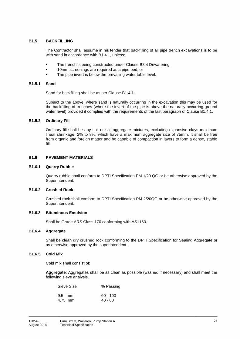
130549 August 2014
Emu Street, Wallaroo, Pump Station A Technical Specification
25
B1.5 BACKFILLING
The Contractor shall assume in his tender that backfilling of all pipe trench excavations is to be with sand in accordance with B1.4.1, unless:
• The trench is being constructed under Clause B3.4 Dewatering,
• 10mm screenings are required as a pipe bed, or
• The pipe invert is below the prevailing water table level. B1.5.1 Sand
Sand for backfilling shall be as per Clause B1.4.1. Subject to the above, where sand is naturally occurring in the excavation this may be used for the backfilling of trenches (where the invert of the pipe is above the naturally occurring ground water level) provided it complies with the requirements of the last paragraph of Clause B1.4.1.
B1.5.2 Ordinary Fill
Ordinary fill shall be any soil or soil-aggregate mixtures, excluding expansive clays maximum lineal shrinkage, 2% to 8%, which have a maximum aggregate size of 75mm. It shall be free from organic and foreign matter and be capable of compaction in layers to form a dense, stable fill.
B1.6 PAVEMENT MATERIALS B1.6.1 Quarry Rubble
Quarry rubble shall conform to DPTI Specification PM 1/20 QG or be otherwise approved by the Superintendent.
B1.6.2 Crushed Rock
Crushed rock shall conform to DPTI Specification PM 2/20QG or be otherwise approved by the Superintendent.
B1.6.3 Bituminous Emulsion
Shall be Grade ARS Class 170 conforming with AS1160.
B1.6.4 Aggregate
Shall be clean dry crushed rock conforming to the DPTI Specification for Sealing Aggregate or as otherwise approved by the superintendent.
B1.6.5 Cold Mix
Cold mix shall consist of: Aggregate: Aggregates shall be as clean as possible (washed if necessary) and shall meet the following sieve analysis.
Sieve Size % Passing 9.5 mm 60 - 100 4.75 mm 40 - 60

130549 August 2014
Emu Street, Wallaroo, Pump Station A Technical Specification
26
2.36 mm 36 - 45 0.75 mm 0 - 2 Emulsion Content: A bitumen content of 5-6% is required.
B1.6.6 Materials Sampling and Testing
The sampling and testing of all materials used in the construction and formation of pavement works, trench bedding and backfilling, shall be arranged and carried out at the expense of the Contractor. The sampling and testing shall be carried out in accordance with the relevant requirements of AS1289 "Methods of Testing Soils for Engineering Purposes". The testing shall be carried out by an independent N.A.T.A. registered testing laboratory. Copies of the test results shall be provided to the Superintendent for his approval at least seven (7) days before use of the material in the Works. If during the progress of the works the materials, from sources originally approved, change in properties, or alternative sources are proposed, further samples shall be tested and the results submitted for the Superintendent's approval. Any material which does not meet the specified requirements may be rejected and shall then be removed from the site by the Contractor and replaced at his own expense.
B1.7 CONCRETE MATERIALS B1.7.1 Cement
Portland cement - Type D (Sulphate resistant) shall be of approved brand to comply with the current Australian Standard Specification. Sulphate resistant cement shall be used in all concrete or mortar that will come into contact with sewage.
B1.7.2 Water
Water shall be clean potable water free from deleterious substances.
B1.7.3 Fine Aggregate
The fine aggregate shall conform with AS2758 and be clean sharp calcareous sand free from loam, clay, silt, vegetable matter, fine dust or other impurities.
B1.7.4 Coarse Aggregate
The coarse aggregate shall conform with AS2758 and be clean, free from loam, soft particles and foreign matter and shall meet the following gradings. Passing a 19.05mm sieve - at least 95% Retained on a 4.76mm screen - at least 95% Calcareous aggregate shall be used where the concrete will come in to contact with sewage.
B1.7.5 Cement Mortar
Cement mortar not in contact with sewage and unless otherwise specified shall be composed of one part Portland Cement, two parts fine aggregate properly mixed with a minimum amount of water necessary to render the mix workable.

130549 August 2014
Emu Street, Wallaroo, Pump Station A Technical Specification
27
B1.7.6 Concrete
Concrete not in contact with sewage and unless otherwise specified shall be composed of Portland Cement, fine aggregate, coarse aggregate and clean potable water thoroughly mixed and comply with the following: General Concrete characteristic compressive strength,
F'C of 32 MPa at 28 days, 80mm slump Concrete used in pump sumps characteristic compressive strength,
F'C of 40 MPa at 28 days, 80mm slump B1.7.7 Steel Reinforcement
Supply reinforcement as detailed, together with tie wire and support chairs necessary for fixing, generally complying with AS1480, free from loose scale, rust, oil, grease or other coatings, bundled and tagged for identification. Use reinforcing bars complying with AS4671.
B1.7.8 Precast Concrete Components
Manholes shall be totally precast manufactured, using sulphate resistant cement and calcareous aggregate, in accordance with SA Water standards or otherwise approved by the Superintendent. The minimum cover to reinforcement bars and tendons, on the internal surface of the maintenance hole, shall comply with the requirements of AS3735 "Concrete Structures for Retaining Liquids", exposure classification "D", Table 4.2 and/or 4.3. Pump Sumps and Storage Tanks shall be totally precast, manufactured using sulphate resistant cement and calcareous aggregate, as shown on the Drawings or otherwise approved by the Superintendent. The minimum cover to reinforcement bars and tendons, on the internal surface of the pump sump, shall comply with the requirements of AS3735 "Concrete Structures for Retaining Liquids", exposure classification "D", Table 4.2 and/or 4.3. Certificates from the manufacturer certifying the use of sulphate resistant cement and calcareous aggregate shall be submitted to the Superintendent prior to the installation of any precast concrete component. Pump Sump Covers shall be checker plate covers manufactured and complying with Clause B1.2.5 of this Specification, unless specified otherwise on Drawings. Lids shall also have hinged aluminium safety grids beneath the plate covers on all chambers. Maintenance Shaft Covers/surrounds shall be of precast concrete with cast iron covers as manufactured by "Everlevel", namely IO102 for 100mm diameter risers and IO152 for 150mm diameter risers. Inspection Point Covers shall be of the dimensions shown on the Drawings using 32 MPa concrete and manufactured by an approved precast concrete manufacturer, "Everlevel" IP 100CF. Openings through precast components shall be precast or saw cut. Chiselled openings shall not be permitted.

130549 August 2014
Emu Street, Wallaroo, Pump Station A Technical Specification
28
B1.8 FERROUS COMPONENTS B1.8.1 Access Covers (Cast Iron) – General
Covers shall consist of a cover and its metal frame as a unit. Circular covers manufactured by one maker shall be interchangeable in any frame. The Contractor shall provide a corrosion-inhibiting coating to all cast iron surfaces. Details of the proposed coating shall be submitted for approval prior to application. The makers name shall be cast into the top surface of the cover or frame. The cover shall consist of cross webbed, cellular construction with the ribs uppermost to allow later infilling with concrete. Cover keyholes shall positively locate lifting keys and shall be fitted with plastic plugs. Keys shall rotate clockwise to stop in key holes.
B1.8.2 Materials
Cover and frame shall be of cast iron grade T200 in accordance with the latest edition of AS1830 - "Grey Cast Iron". Frame bolts shall be hot dip galvanised.
B1.8.3 Tolerances and Dimensions
The maximum tolerance on mating face alignment and segmented cover surface level shall be 0.25mm. The horizontal and vertical mating faces of the cover and frame shall be machined to permanently eliminate movement due to traffic and to provide a gas tight and waterproof seal when coated with the equivalent of 0.25mm of grease. Bearing surfaces shall be at least 20mm wide for light duty covers and 30mm wide for heavy duty covers. Matched covers and frames shall provide a clear opening of 600mm diameter for circular covers as specified or shown on the Drawings.
B1.8.4 Identification Disk
The identification disk to be made from cast iron grade T200 in accordance with AS1830 "Grey Cast Iron" cast as detailed on the Drawings.
B1.8.5 Checker Plate Covers, Frames and Fittings
Shall be fabricated as detailed on the Drawings and hot dip galvanised all in accordance with Clause B1.2.6.
B1.9 FENCING
All fencing shall be constructed and positioned as shown on the Drawings.

130549 August 2014
Emu Street, Wallaroo, Pump Station A Technical Specification
29
B2. CONCRETE CONSTRUCTION STANDARDS
B2.1 SCOPE
Unless concrete components are made by an approved pre-cast concrete manufacturer, they shall be cast in site using ingredients complying with Section B1 of this Technical Specification and conform with the following mixing and construction standards.
B2.2 MIXING
The selection of the mix materials and proportions of the mix to achieve the specified concrete standard shall be the responsibility of the Contractor.
B2.2.1 Site Mixed Supply – Concrete
STANDARD: To AS3600, in an approved plant complying with the relevant requirements of AS1379. ELAPSED TIME: Site mixed concrete is liable to be rejected if the elapsed time between the wetting and the discharge of the mix exceeds 45 minutes. MIXING TIME: Not less than 90 seconds for mixes of 1m
3 or less. Increase by 30 seconds for
each additional cubic metre or part thereof. EMERGENCIES: Mixing by hand in emergencies is not permitted.
B2.2.2 Ready-Mixed Supply – Concrete
STANDARD: To AS1379, from an approved supplier. Deliver in agitating trucks. ELAPSED DELIVERY TIME: Concrete is liable to be rejected if the elapsed time between the wetting of the mix and the discharge of the mix at the site exceeds the following: CONCRETE TEMPERATURE MAXIMUM ELAPSED TIME at time of discharge (hours) 10°C - 24°C 2.0 24°C - 27°C 1.5 27°C - 30°C 1.0 30°C - 32°C 0.75 DELIVERY DOCKET: The Contractor shall obtain a docket with each batch, containing the information required by AS1379, and stating in addition:
• the concrete element or part of the works for which the concrete was ordered;
• the total amount of water as delivered and the amount to be added at the site; and
• the source of the coarse aggregate. The Contractor shall keep all dockets and make them available to the Superintendent on request. SITE ADDITIONS: The Contractor shall not add water or any other material to the concrete at the site without approval.
B2.2.3 No-Fines Concrete – Concrete
MATERIALS: Cement and coarse aggregate.

130549 August 2014
Emu Street, Wallaroo, Pump Station A Technical Specification
30
Aggregate grading: Sieve size (mm) % passing
37.5 100 19 95-100 9.5 0-5 PROPORTIONS: (Aggregate: cement): 6:1 to 8:1 by weight. WATER/CEMENT RATIO: 0.35 to 0.45 by weight.
B2.2.4 Inspection and Testing
The Contractor shall give the Superintendent 24 hours’ notice so that an inspection may be made of the following:
• completed form work,
• reinforcement fixed in place,
• cores and embedments fixed in place, and
• placing concrete.
For all concrete structures poured in-situ, the Contractor must conduct three cylinder tests from each batch at 14 days, 28 days and 56 days as well as a slump test.
B2.2.5 Rejection – Concrete
The Superintendent may reject concrete on the basis of: CRITERIA: To AS 3600. The Contractor shall remove rejected concrete to the extent determined by the Superintendent at no cost to the Principal. The Superintendent may permit the retention of concrete liable to be rejected, on the basis of:
• An appraisal of the statistical information related to the concrete strength;
• A structural investigation;
• Additional tests, eg. to AS3600; and/or
• Approved remedial work.
B2.2.6 Formwork
Formwork shall conform to AS3610 so that concrete, when cast in the forms, will have the dimensions, shape, location and surface finish required by the Contract. The Contractor shall be, responsible for the sufficiency of the formwork, except to the extent, if any, that formwork design is shown on the Drawings or specified. If formwork fails to meet the requirements of the Contract, the Superintendent may reject it and any concrete which has been cast in it. In that case, remove the rejected concrete, form construction joints, reconstruct the formwork and recast the concrete.
B2.2.7 Dimensional Tolerances – Concrete
The formwork shall conform with Class 3 as described in AS1510 and shall have a:

130549 August 2014
Emu Street, Wallaroo, Pump Station A Technical Specification
31
• maximum deviation of 20mm from the correct position; and
• maximum misalignment of 2mm between pours or across joints with a maximum finish or recess of 3mm.
B2.2.8 Formed Surfaces
Formed surfaces shall be Class 3 for exposed surfaces and internal faces of maintenance holes and pump stations and Class 5 on all other surfaces.
B2.2.9 Lost Formwork – Concrete
Permanent or lost formwork, if required, shall be incombustible, shall not contain calcium chloride, and shall not impair the structural performance of the concrete.
B2.2.10 Form Coatings – Release Agents
FORM COATINGS - shall conform to AS3610 RELEASE AGENTS - shall conform to AS3610 FORMWORK REMOVAL - shall conform to AS3610
B2.3 PLACING B2.3.1 Weather Conditions
Concrete shall not be mixed or placed in temperatures less than 5°C and above 32°C unless approved by the Superintendent.
B2.3.2 Placing
Placing procedures shall generally comply with AS3600. The Contractor shall:
• Not attempt to move a mass of concrete along the forms to its final position. Movement may be by means of suitable clean chutes, troughs or pipes. The Contractor shall not use water to facilitate the movement.
• Limit the free fall of concrete to 1500mm per 100mm element thickness, by means such as enclosed chutes, access hatches in forms, and the like. As far as practicable keep chutes vertical and full of concrete during placement, with ends immersed in the placed concrete.
• Place concrete in layers not more than 300mm thick. Each layer shall be compacted before the preceding layer has taken its initial set, so that the two are blended by the compaction process.
Concrete exposed to rain before it has set, including during mixing, transport or placing, shall be liable to rejection.
B2.3.3 Compaction
Concrete shall be compacted in accordance with the provisions of AS 3600 using approved concrete immersion vibrators. Concrete shall be vibrated to achieve a dense concrete. Care
130549 August 2014
Emu Street, Wallaroo, Pump Station A Technical Specification
32
shall be taken not to over-vibrate concrete or for vibrators to come in contact with partially set concrete.
B2.4 CURING
Curing procedures shall conform to AS3600. The Contractor shall protect fresh concrete from premature drying and excessively hot or cold temperatures. Concrete shall be maintained at a reasonably constant temperature with minimum moisture loss for the curing period. Unless otherwise specified, concrete shall be cured continuously until the cumulative number of days or fractions thereof, not necessarily consecutive, during which the air temperature in contact with the concrete is above 10°C, totals not less than the following:
• Concrete made with normal or sulphate resistant, Portland cement: = 7 days
B2.5 PROTECTION
The Contractor shall:
• protect the concrete from damage due to load over stresses, heavy shocks and excessive vibrations, particularly during the curing period; and
• protect finished concrete surfaces from damage from any cause, including mortar splashes and stains, timber stains, rust, stains, chemical attack, additives, curing compounds, protective coatings, rain, running water, and the like.
B2.6 PRECAST UNITS
B2.6.1 Standard
Precast units shall conform to AS3850, and where applicable AS3735, and shall be manufactured by an approved sub-contractor.
B2.6.2 Marking and Identification
Marking and identification shall conform to AS3850. A replacement unit shall not have the same marking as the rejected unit it replaces.
B2.6.3 Handling Precast Units
Handling precast units shall conform to AS 3850. The Contractor shall not place lifting attachments, holes and other temporary fixings for handling purposes on visible faces of units unless otherwise approved. Recess lifting attachments such as ferrules, or other types of cast-in fixings shall be provided and these shall have approved plugs for sealing. Remove temporary attachments after erection and seal or otherwise make good to approval any residual recesses.
B2.6.4 Installing Precast Units – Concrete
The Contractor shall fix precast units securely in their final positions within the specified tolerances. All necessary components and materials shall be supplied and fixed in place, including fixings, temporary fixings, braces, shims, jointing strips, sealant, flashings, grout, mortar and the like, as shown on the Drawings.

130549 August 2014
Emu Street, Wallaroo, Pump Station A Technical Specification
33
B2.6.5 Precast Dimensional Tolerance
Precast dimensional tolerances shall conform with tolerances stated in AS3850.
B3. EXCAVATION, BACKFILL AND REINSTATEMENT
B3.1 NOTICE BEFORE COMMENCEMENT OF WORKS
Before commencement of the works in any area and/or before entry into private property to carry out the works of the Contract, the Contractor shall give notice to the occupier(s) of land as set out in Clause A14.
B3.2 SITE PREPARATION B3.2.1 Site Preparation
The Contractor shall take all necessary precautions and care to avoid damage to existing services, fences or other improvements on or in the vicinity of the site and to minimise disturbance of any trees which are to remain after construction. Trees shall be removed only where necessary for the construction of the works, where nominated on the Drawings or as otherwise authorised by the Superintendent. Where trees are removed, stumps and root systems shall be removed as directed by the Superintendent. The excavation shall be backfilled with Class "C" Ordinary Fill, material compacted in accordance with Clause B3.7.5. The site shall be cleared only in those parts on which the works are to be carried out. All clearing shall be carried out by the Contractor at his expense. All materials resulting from the clearing shall be removed from the site, with the exception of any materials required to be retained by the property owner, by the Contractor at his expense.
B3.2.2 Topsoil
Topsoil shall be stripped from all areas where works are to be constructed and shall be stockpiled on the site to reinstate footpath areas, nature strips, batter slopes, allotments (including easements) and all other such areas to make good. Topsoil shall be imported if required. Minimum topsoil thickness to be 150mm. Imported topsoil shall be clean, free from clay, stones, lumps, organic material and be obtained from an area free from noxious weeds and seeds. The source shall be approved by the Superintendent.
B3.3 EXCAVATION B3.3.1 General
All excavations shall have uniform vertical sides to the dimensions, levels, clearances and tolerances prescribed unless otherwise approved by the Superintendent. The floor of excavations shall be trimmed to remove all intrusions and loose material to produce a firm sub-grade of a depth which will provide for a uniform sand or aggregate bedding beneath the drain or structure.
130549 August 2014
Emu Street, Wallaroo, Pump Station A Technical Specification
34
• For gravity drains, the width of trench excavation shall comply with Clause 5.2.2.3 of Australian Standard AS2032, namely "The trench shall be excavated, trimmed to the required grade, and should be as narrow as practicable. The bed width should be not less than 200mm wider than the outside diameter of the pipe for pipes of 100mm nominal size and above, and not less than twice the pipe diameter for smaller pipes. Where required, the trench should be wide enough for inspection purposes.
• For rising mains, the width of trench excavation shall comply with Clause 4.2.2.3 of Australian Standard AS2033, namely "The trench shall be excavated, trimmed to the required grade, and should be as narrow as practicable. The bed width should be not less than 200mm wider than the outside diameter of the pipe for pipes of 125mm nominal outside diameter and above, and not less than twice the pipe diameter for smaller pipes. Where required, the trench should be wide enough for inspection purposes.
• The trench width shall otherwise be determined by the Contractor and shall be sufficient to allow unrestricted access for the preparation of pipe bedding and installation of the pipe and to allow for the thickness of all necessary shoring.
• Not more than 200m of trench shall be opened by a drainage gang on a drain line unless approved by the Superintendent.
• Excavation for maintenance holes, pump stations etc. shall be uniform in shape and of the minimum clearance outside the walls of the structure to permit safe access for making pipe connections and sealing joints.
B3.3.2 Hand Digging of Trenches
The Contractor shall allow in his tender for hand digging and backfilling of trenches to provide for areas which are made inaccessible by sheds, large trees, etc.
B3.3.3 Mechanical Boring & PVC Sleeving
The installation of drains by underground mechanical boring will be permitted, to avoid disruption to property, subject to the approval of, or at the direction of the Superintendent. All bored drains shall be laid at a minimum 2% grade unless otherwise specified. They shall be a minimum PN12.5, and shall be the equivalent size of the nominated uPVC drain. An inspection outlet shall be placed at the join between the PVC and HDPE drains. A puddle flange shall also be installed adjacent the PVC/HDPE join. The Contractor shall supply a rig that is capable of drilling through rock from the nominated entry and exit pit locations. The Contractor will be paid for boring through rock as an over and above cost. However, the Principal will not pay for re-establishment of the rig if it is not able to drill in rock.
B3.3.4 Tolerances
The permitted tolerance of excavations shall not exceed:
• Sides of excavations ± 50mm from the specified position.
• Floor of excavation ± 25mm from the specified depth. B3.3.5 Over Excavation
Over Excavation in Clean Sand Over excavation in clean sand shall be backfilled to the design trench floor level with the excavated sand, compacted to 90% Standard Dry Density.
130549 August 2014
Emu Street, Wallaroo, Pump Station A Technical Specification
35
Over Excavation in Stable, Dry Conditions Over excavation in stable, dry conditions shall be made good with sand as per B1.5.1. Over Excavation in Soft Clays Over excavation in soft clays shall be made good by placing an approved geotextile fabric on the over excavated trench floor, extending up the sides of the trench to at least the mid height of the pipe. The over excavation shall then be backfilled to the design trench floor level with imported material similar to the pipe bedding material, with cement treated quarry waste or other material approved by the Superintendent, and shall be compacted to the satisfaction of the Superintendent. All over excavation shall be made good by the Contractor at the Contractor's expense.
B3.3.6 Excess Soil and Rock
The Contractor shall stock pile excess soil and rock at the location nominated by the Superintendent. The Contractor shall separate limestone rock and mixed loads, and stock these in separate piles on the site.
B3.3.7 Excavation Under Obstructions
The Contractor shall allow, in his tender, for all hand digging involved in exposing and excavation adjacent to and under services, pipes, spoon drains and road kerbings etc, and all excavation shall be as far as practicable, be carried out by tunnelling. Any damage incurred shall be reinstated at the Contractor's expense to the satisfaction of the Superintendent. The Contractor shall ensure that due care is taken to compact the backfill material under kerbs and services to the satisfaction of the Superintendent.
B3.3.8 Responsibility for Damage by Floodwaters, etc
The Contractor shall be deemed to have fully informed himself concerning the rise and fall of any adjacent water courses in as far as it may affect his work and the Principal will not accept any responsibility for loss of, or damage to the structures, the Contractors plant or materials, due to flooding. The Contractor shall be fully responsible and reinstate at his own cost any drain or structure which has been installed and subsequently damaged or adversely affected due to storm water, flooding or from any other cause during the currency of the Contract. The Contractor shall be responsible for protecting all excavations from the entry of surface runoff produced by rainfall and shall make good damage caused by such runoff. Should the Contractor interfere with or divert the natural flow of any watercourse, surface or stormwater such interference or diversion shall be approved by the Superintendent. The Principal shall be fully indemnified by the Contractor against flood damage to the works to the date of the expiry of the maintenance period.
B3.3.9 Trenches Open Exceeding 48 Hours
If the Superintendent deems it necessary, he may order the Contractor to backfill any trench or excavation or part thereof where no work has been carried out over a period exceeding 48 hours. Should the Contractor fail to backfill such trench or excavation as directed the Principal

130549 August 2014
Emu Street, Wallaroo, Pump Station A Technical Specification
36
may carry out the work and recover the cost by deduction from payments to the Contractor. The Contractor shall have no claim for any loss suffered by him in consequence of such direction.
B3.3.10 Excavation – Bituminised Roads
Where any excavation is to be carried out along or across any bituminised or sealed roads, the Contractor shall cut the sealed or bituminised surface with a carborundum or other approved type of mechanical saw or equipment. The saw cut shall be made to the full depth of the bitumen surface. The Contractor shall allow, in his tender, to make two parallel cuts at a width 500mm wider than the intended trench excavation. The trench shall be excavated centrally within the saw cuts. In the case of a spray seal, the Contractor shall be permitted to make the cuts after the trench has been excavated. This will be done at the Contractor’s discretion and any tear-outs resulting from not pre-cutting the seal shall be reinstated at the Contractor’s expense. The width between the saw cuts shall allow for additional excavation width necessary to provide for shoring. The Contractor shall carry out the excavation, placement and removal of shoring, dewatering equipment, pipe bedding and installation, backfill, compaction and reinstatement with all due care and in such away so as to prevent damage to the sealed surface outside the saw cuts. Should any damage occur outside the area contained by the saw cuts, a new saw cut shall be made by the Contractor as directed by the Superintendent to provide a neat clean edge to match to when reinstating the seal. The Contractor shall be responsible for all costs associated with such additional reinstatement, unless in the opinion of the Superintendent, that although the Contractor had taken due care, the damage/overbreak outside the saw cuts was unavoidable due to ground conditions or the nature or condition of the road base materials and/or surface, in which case the Contractor shall be paid for additional saw cutting, reinstatement of the road base and sealed surface at the rates provided in the Schedules submitted with the Tender. The Contractor should note that the rates submitted in the Tender shall be examined against a predetermined quantity for the purpose of Tender assessment.
B3.4 DEWATERING B3.4.1 By Sump Pump
Where groundwater is encountered, the Contractor shall be responsible for dewatering the excavation in a safe and efficient manner. Where possible, a sump pump shall be used, in association with aggregate pipe bedding and initial backfill, to maintain groundwater at 50mm below the invert level of the pipe. The Contractor shall make due allowance in his Tender for all dewatering where ground water is encountered using sump pump techniques.
B3.4.2 Well Point Dewatering – Provisional Sum
Where sump pump techniques will not maintain the ground water at 50mm below the invert level of the pipe, "well point equipment" shall be used to de-water the excavation. The Contractor shall install sufficient "well pointing" as indicated by the site conditions sufficiently ahead of the excavation to draw down the water table below the bottom of the trench.

130549 August 2014
Emu Street, Wallaroo, Pump Station A Technical Specification
37
Well point dewatering shall be paid for in accordance with the unit rates within the schedule supplied with the tender. The unit rate shall be over and above the tender allowance for sump pump dewatering. When costing the above schedule of rates to determine the provisional quantity, the well point dewatering method adopted by the Contractor shall allow for at least the following:
• 1.5m well point spacing up to 6m deep;
• A single sided arrangement; and
• A 48 hour draw down period. If more extensive dewatering system requirements are needed then this shall be negotiated on site with the Superintendent. A Provisional Sum shall be allowed for in the tender for well point dewatering, including up to 10 deployments of the dewatering equipment. This quantity could either increase or decrease according to field findings and measurement certified by the Superintendent and adjustment shall be made, in accordance with the General conditions of Contract, at the rate provided by the Contractor with his Tender. The unit rate shall provide for the degree of difficulty associated with dewatering, damage to equipment, reinstatement of road surfaces damaged by the installation of equipment, aggregate bedding and cover, and geotextile fabric (as provided below). All transportation of equipment to and from the site, assembly of equipment and installation, servicing and attendance, removal and disassembly, stand down of equipment when not required but still on site shall be provided for in the establishment / disestablishment cost. In addition to the above, the unit rate shall be deemed to provide for all additional costs to the Contractor, such as overhead and profit, associated with the existence of the ground water including all consequential costs such as decreased rates of production. A deployment shall be deemed to be the establishment and associated disestablishment, of well points inside a pump station catchment. If several lines require dewatering inside a catchment area or if dewatering along one line requires several pump setups this will be deemed as one establishment of the dewatering equipment. The method used in assessing payment on this item shall be the length of trench in which groundwater was intercepted and or the length of trench agreed by the Superintendent as being necessary to dewater using well point equipment.
B3.4.3 Pipe Bedding in Ground Water
The Contractor shall allow in his tender for bedding and initial backfill in trench excavations requiring dewatering as follows: Where the trench excavation requires dewatering, geotextile fabric shall be placed over the floor of the trench, extending up the sides of the trench to at least the mid height of the pipe before placement of the bedding material. Bedding material shall be 10mm single aggregate bedding. Initial backfill over the pipe to a level of 200mm above the top of the pipe shall be as for bedding material; this shall be covered with geotextile fabric before placing any excavated and/or imported trench backfill material.
B3.5 ROCK EXCAVATION - PROVISIONAL SUM
The construction of the works will require the excavation of rock. The Contractor shall allow in his Tender a Provisional Sum for the excavation of rock. This sum could either increase or

130549 August 2014
Emu Street, Wallaroo, Pump Station A Technical Specification
38
decrease according to field findings and measurement certified by the Superintendent and adjustment shall be made, in accordance with the General conditions of Contract, at the rate provided by the Contractor with his Tender. Providing levels etc. permit, a drain located in rock may be raised or relocated subject to the approval of the Superintendent.
B3.5.1 Use of Explosives
Under no circumstances shall explosives be brought to the site or used in connection with any part of the Contract, unless directed by the Principal in writing.
B3.5.2 Definition of Rock
For the purposes of interpretation, measurement and/or payment relevant to the term "rock" as mentioned throughout this Specification, rock shall be defined as only that material found in ledges, masses, bedded deposits and/or conglomerate deposits so firmly cemented and presenting the characteristics of rock which in the opinion of the Superintendent cannot be removed by using an excavator with tiger teeth rated at 20 tonne and would normally be removed by pneumatic tools or mechanical impactor. Where due to limited access the use of a machine as above is impracticable, a side shift excavator rated at12 tonne will be approved. Floaters in trenches, foundations or similar excavations shall be classified as rock only when their least dimension exceeds 0.6m or where their volume exceeds 0.25m
3.
Materials which, in the opinion of the Superintendent, could be excavated by the above rated plant such as such as broken shale, coastal limestone, weak conglomerates, etc. shall not be classified as rock for purpose of payment. The Contractor is to provide a separate rate for the use of a rock saw (as included in Tender Schedules).
B3.5.3 Measurement and Payment of Rock Excavation
Note that this Clause refers only to rock excavation for the drainage works (i.e. gravity drains, maintenance holes, flushing points, pump stations and rising mains). Actual payment for rock excavation in drainage works shall be made on the following basis:
• The Contractor shall include in his tender a unit rate per cubic metre of rock excavation as set out in the Schedules submitted with the Tender.
• The unit rate shall be deemed to provide for all plant, equipment, labour and all additional costs to the Contractor, such as overhead and profit, associated with the existence of rock including all consequential costs such as decreased rates of production.
• The schedule rates shall apply to rock as measured jointly by representatives of the Contractor and the Principal.
• The rock shall be measured in the solid form, within the limits of the trench excavation, before any backfilling is placed, or new work commenced.
• The limits of the trench excavation shall be determined at 450mm maximum trench width. Where it is necessary to provide shoring within the excavation a maximum trench width of 600mm shall be allowed, or as approved by the Superintendent. Where common service
130549 August 2014
Emu Street, Wallaroo, Pump Station A Technical Specification
39
trenching is provided the trench width, for the purpose of measurement of rock, shall be approved by the Superintendent.
• No payment shall be made for over break beyond the limits of the required excavation.
• The Contractor shall keep a daily record of the agreed volume of rock excavated, detailing:
• the drain line no;
• the chainage at which the rock was encountered;
• the agreed volume of rock excavated; and
• the rate applicable to the rock excavated.
These details shall be verified and certified by the Superintendent, daily.
• The Contractor shall provide two copies of the verified certificate to the Superintendent for his records.
• Payment for rock shall be made only when the Superintendent deems the material to comply with the definition for rock.
B3.6 SHORING
B3.6.1 General
The Contractor shall allow in his Tender for all provisions for shoring. No additional payments will be made by the Principal for shoring of trenches. The Contractor shall put in place and maintain such sheeting, bracing, timbering or a patent shoring system to prevent collapse of earth adjoining the excavation. The system used shall be installed to protect the safety of workers in conformity with the provisions of the regulations under the Occupational Health, Safety and Welfare Act and facilitate efficient construction practices. If approval is given to batter or shelve the sides of trenches, no additional payment will be made. The Contractor shall meet the full costs of extra excavation and restoration and for any required increase in pipe strength. The responsibility for stability of any such battering or shelving shall remain with the Contractor. For the purpose of preventing injury to persons or damage to property, the Superintendent may direct that any shoring more than 1.5m deep be left in place and the shoring above that level cut off and removed from the site. The Superintendent may order the provision of shoring at any location deemed necessary to protect the stability of the excavation and the safety of workman and property. Any direction or lack of direction given by the Superintendent shall not relieve the Contractor of any responsibility regarding the provisions of shoring.
B3.7 BACKFILL B3.7.1 Initial Backfill, Drains, Rising Mains
After the line and level of the drain has been approved by the Superintendent, the Contractor shall cover the drain with sand if the bedding is sand and 10mm screenings if the bedding is of screenings, to at least 200mm above the top of the drain. Such cover shall be spread uniformly
130549 August 2014
Emu Street, Wallaroo, Pump Station A Technical Specification
40
over the full length and width of the trench and shall be compacted using hand compaction tools or by flooding to the satisfaction of the Superintendent. The Contractor shall place the initial and subsequent backfill carefully and in such a way that the drain and appurtenances are neither damaged nor disturbed. If conditions are such as to require screenings as bedding material and cover over the drain, the screenings shall be covered with a geotextile fabric for the full width of the trench prior to placing the backfill material (Refer also Clause B3.4.3).
B3.7.2 Backfill Generally
Following placement of the initial backfill and on receipt of approval by the Superintendent, final backfill shall be placed, spread and compacted as follows: Within Council roadways and other trafficable areas as defined herein Class ”B” backfill Within footways Class “C” backfill Within private property Class “D” backfill
B3.7.3 Backfill Class “A”
Shall be in accordance with the “Standard Specification for Excavation and Reinstatement of Road Pavement” issued in October 2010 by DPTI and any relevant update there part of.
B3.7.4 Backfill Class “B”
Backfill Class “B” shall be of sand as specified in Clause B1.5.1 uniformly compacted in horizontal layers of 300mm loose thickness to not less than 95% of the maximum dry density, (Standard), to within 600mm of the finished level and not less than 98% (Standard) at all levels above 600mm below finished surface in accordance with AS1289, to 200mm below the road pavement or finished surface level. The top 200mm shall be backfilled with 20mm quarry waste as specified in Clause B1.6.1. and uniformly compacted to not less than 96% of the maximum dry density (Modified), in accordance with AS1289.
B3.7.5 Backfill Class “C”
Backfill Class “C” shall be "ordinary fill", as specified in Clause B1.5.2., uniformly compacted in horizontal layers of 300mm loose thickness to not less than 95% of the maximum dry density, (Standard), in accordance with AS1289 to 100mm below the finished surface level. The top 100mm of the trench shall be backfilled with 20mm quarry waste compacted to 95% Standard.
B3.7.6 Backfill Class “D”
Backfill Class “D” shall be "ordinary fill" as specified in Clause B1.5.2 uniformly compacted in horizontal layers of 300mm loose thickness to not less than 90% of the maximum dry density, (Standard), in accordance with AS1289 to natural surface.
130549 August 2014
Emu Street, Wallaroo, Pump Station A Technical Specification
41
B3.7.7 Definitions
Roadway shall be all of the formed or unformed, sealed or unsealed portion of the road reserve not allocated as footpath. Footpath shall be the formed or unformed, sealed or unsealed portion of the road reserve not allocated as roadway. Where the footpath is not clearly defined by kerbing or other means the width of the footpath area shall be three (3) metres from the boundary of the road reserve. Private Property shall be all property not classified as road reserve.
B3.8 REINSTATEMENT OF PROPERTY, PAVEMENTS AND FOOTWAYS B3.8.1 Making Good
The Contractor shall make good without compensation, unless a specific Provisional Sum is provided, all damage caused to the existing buildings, ground, gates, fences etc, and shall reinstate damaged paving in private premises to the same condition as they were before the work commenced. Making good shall include making good settlement, soil subsidence and any damage or defect caused by settlement. Any works or structure passed as satisfactory pursuant to the provisions of this Clause shall not release the Contractor from his obligations under the maintenance provisions of the Contract to make good or maintain any settlement or damage caused by the settlement to the date at which the maintenance period expires. If after 48 hours of the completion of any drain or appurtenance in any area the Superintendent considers the cleaning up, making good or reinstatement to be unsatisfactory he will visit the area with the Contractor and issue such necessary directions to have the area brought to the same conditions as existed prior to the commencement of work. Should the Contractor fail to complete this work within the time specified by the Superintendent, the Principal may carry out the work and deduct the costs incurred from payments made to the Contractor under the conditions of the contract.
B3.8.2 Reinstatement of Roads & Footways
General Any damage to any roadway or footpath during the carrying out of the Contract shall be made good, at the Contractor's own expense, to the satisfaction of the appropriate authority and the Superintendent. Any paved surfaces, whether concrete or bitumen, that have been destroyed, damaged or removed by trenching operations or plant shall be reinstated by the Contractor to the satisfaction of the Superintendent (refer also to Clause B3.3.10). Council Roads Council roads shall be reinstated to match the existing pavement shape as follows: Hotmix Asphalt Pavements Where the existing surface is hotmix asphalt, the Contractor shall: a. Excavate to 30mm below the final level to allow for new asphalt.

130549 August 2014
Emu Street, Wallaroo, Pump Station A Technical Specification
42
b. Trim and compact the crushed rock to not less than 98% of the maximum dry density
(Modified) in accordance with AS1289. c. Apply an emulsion prime CRS60 to the crushed rock at a uniform application rate of 0.55
L/m2. d. Place and compact the Bituminous Hotmix by an approved method. The amount of
Hotmix shall be sufficient to level out under the effects of compaction to result in a minimum compacted thickness of 30mm and to provide a smooth ride for passing traffic.
On completion of compaction, the Hotmix shall be dusted with fine aggregate to prevent “pick-up”. The Contractor shall schedule the Hotmix surfacing so that trenches are not left unsealed for an unreasonable length of time, as determined by the Superintendent, while avoiding working in excessively small sections. Where reinstatement of the sealed surface is not to be carried out immediately after backfilling and compaction, the Contractor shall place the base course material up to the adjacent road surface level and open the road to traffic. The Contractor shall maintain the temporary road surface in a trafficable condition up until placement of the Hotmix. Spray Seal Pavements Where the existing surface is a spray seal, the Contractor shall use a 14mm/7mm double coat seal. The residual cold bitumen application rates shall be 1.3 L/m2 and 1.1 L/m2 and the spread rate shall be 90 m
2 per cubic metre and 130 m
2 per cubic metre respectively.
a. Where the existing seal has been damaged beyond the initial saw cuts (refer Clause
B3.3.10), the Superintendent and the Contractor shall agree on a seal width to best suit the section of road requiring reseal.
b. The Contractor shall then box out the trench ensuring that a clean cut edge is obtained
on the damaged section of road. This can be achieved with a mechanical saw or grader blade or other method approved by the Superintendent.
c. The top 200mm of the trench shall be filled with crushed rubble (PM 2/20QG). The trench
shall be left proud to enable trimming to be done prior to the application of the seal.
d. The final surface of the basecourse is to be inspected by the Superintendent prior to applying the first coat of seal. The surface shall be a trimmed, uniform, tight marix and shall be swept prior to seal application.
e. The first seal coat shall be placed flush with the existing surface and be rolled with a
pneumatic roller prior to the application of the second coat.
f. The second coat shall overlap the first coat by 100mm and be rolled with a pneumatic roller to the satisfaction of the Superintendent.
Settlement Trenches in Council roads shall be maintained in a safe trafficable condition throughout the duration of the Contract.

130549 August 2014
Emu Street, Wallaroo, Pump Station A Technical Specification
43
Reinstatement of Defective Roadways Where the pavements of existing roads which are cut by excavations under the Contract are defective, the Contractor shall notify the Superintendent prior to the commencement of works so that the extent and standard of reinstatement can be agreed with the Superintendent prior to excavation commencing.
B3.8.3 Reinstatement of Footways
Footways shall be reinstated as for Council roads using the following pavement standards: Earth Footways - reinstate with 100mm of compacted topsoil (refer to Clause B3.2.2) to match existing formation.
Gravel Footways - reinstate with 100mm of compacted quarry waste to match existing formation. Paved Footways - pavement to match existing materials, shape and finish.
B3.8.4 Reinstatement of Defective Footways
As for Defective Road Pavements (refer to Clause B3.8.2).
B3.8.5 Compaction Testing
Unless specified otherwise by the relevant authority, compaction testing of pipe backfill is required at a rate of one (1) test set per one hundred (100) metres. Each test set is to contain the three (3) tests, one at each of the following locations: 1. Pipe haunch, side or overlay zone (within 200mm of top of pipe) 2. Backfill zone (depth to vary across test sets) 3. Subgrade Note: Requirement for subgrade compaction testing may be deleted where no pavement reinstatement is required Where compaction test results do not meet the required compaction standards, the Contractor shall be responsible for all re-work and testing associated with bringing the section of trench up to the required standard. Testing shall be carried out by such persons as shall be approved by the Superintendent.
B3.8.6 Compaction Testing – Provisional Sum
The Contractor shall include in his Tender a Provisional Sum for testing of trench compaction as judged necessary by the Superintendent. Where compaction test results do not meet the required compaction standards, the Contractor shall be responsible for all re-work and testing associated with bringing the section of trench up to the required standard. Testing shall be carried out by such persons as shall be approved by the Superintendent. Testing shall only be paid for as a Provisional Cost when the testing is requested by the Superintendent. Any testing completed by the Contractor for his own records or quality system or any re-testing following a failure shall be at the Contractor’s expense.

130549 August 2014
Emu Street, Wallaroo, Pump Station A Technical Specification
44
B3.8.7 Collapsing Soils
The Contractor shall allow in his Tender for all provisions for areas where collapsing soils may affect trenches. No additional payments will be made by the Principal for implications of collapsing soils in trenches (ie. full allowance for closed shoring and additional reinstatement for break out areas).
B4. GRAVITY DRAINS, RISING MAINS AND MAINTENANCE HOLES
This section covers the standards of workmanship for the installation and testing of all drains, maintenance holes, flushing points and property connections.
B4.1 INSTALLATION OF DRAINS, RISING MAINS AND PROPERTY CONNECTIONS B4.1.1 Storage and Handling of uPVC & Polyethylene Pipes
All pipes and fittings shall be handled in accordance with AS2032 and AS2033. Any pipe or fitting which, in the opinion of the Superintendent, is excessively bowed, distorted or damaged, shall not be used, and shall be replaced by the Contractor at his expense.
B4.1.2 Cooling of uPVC Drains before Backfilling
Backfilling of the pipe should not proceed if the temperature of the pipe is likely to be significantly greater than the surrounding earth and the joints have not been given the time specified by the solvent manufacturer for curing. In these conditions, backfilling should be delayed until cooler conditions prevail (e.g. early morning) or the pipes should be cooled by filling the line with cold water, or as directed by the Superintendent.
B4.1.3 Excavation
As specified in Clause B3.3.
B4.1.4 Pipe Bedding
Where naturally occurring dry conditions are found to exist in the trench, drains and rising mains shall be laid on a sand bedding. Where the ground watertable, prior to the commencement of excavation and installation of the drain or rising main, is above the base of the trench, the drain or rising main shall be laid on a bed of 10mm aggregate except as provided for in Clause B3.4.3. Prior to placement of the bedding, the Contractor shall obtain the Superintendent’s approval to ensure that the base of the trench is free from uncompacted material and is sound and does not require any form of "stabilising treatment" to ensure adequate support of the drain or rising main. The bedding shall be spread, compacted and evenly graded over the full width of the trench to a uniform depth of not greater than 75mm below the underside of the drain or rising main so as to provide uniform support for the drain or rising main over its full length.
B4.1.5 Trench Base Stabilisation
If, in the opinion of the Superintendent, the condition of the trench is such as to indicate that stabilisation of the base is necessary to provide adequate support for the drain, the trench shall be over-excavated to 450mm below the normal bed level. A layer of geotextile fabric shall then be placed on the base of the trench extending 450mm up the sides of the trench. This shall be followed by a layer of cement treated quarry rubble which shall be tamped with the excavator

130549 August 2014
Emu Street, Wallaroo, Pump Station A Technical Specification
45
bucket or similar and levelled to provide a uniformly graded sub-base 450mm thick, on which the bedding of screenings shall be placed as specified above. The Contractor shall provide a unit rate in his Tender which shall be used as the basis of payment for this item. The unit rate shall be deemed to provide for all materials, plant, equipment, labour necessary to stabilise the trench as provided above and all additional costs to the Contractor, such as overhead and profit, associated with the necessity to stabilise the trench base, including all consequential costs such as decreased rates of production.
B4.1.6 Pipe Laying
a. Line and Level
The Contractor shall install all drains and rising mains in accordance with alignments, levels and gradients shown on the Drawings and/or the Schedule of levels provided in the Contract Documents. Clearances between sewers and other underground services are to be in accordance with Table 4.2 of the Sewerage Code of Australia (WSA 02-2002-2.2) or the service authority requirement, whichever is the greater. The work shall be carried out by a competent drain layer in accordance with the requirements of AS2032 and AS3500 and to the approval of the Superintendent.
b. Sequence and Tolerances for Pipe Laying
The laying of drains and rising mains shall be commenced at the lower or outlet level and proceed to the higher level with pipe faucets, when laid, facing upstream. The pipes when laid to line and level shall be within the following tolerances. Alignment ± 25mm and not more than 5mm deviation in any 3m length. Level ± 10mm from design invert and not more than 5mm deviation in grade in
any 3m length.
c. Vertical Risers to Flushing Points and Property Connections The vertical riser to flushing points and property connections shall be installed plumb to the axis of the through drain and at 90 degrees to the flow taking into account the drain line gradient. Deviation from any point on the riser from its correct position shall not exceed one half pipe diameters from the base.
B4.1.7 Solvent Welded Joints – uPVC
Solvent welded joints shall be formed in the following manner: a. Cut the pipe end to be jointed shall be cut in a mitre box. All such cuts to be made
square with the axis of the pipe being cut. or Cut the pipe end to be jointed using an approved pipe cutter. b. Remove all burs from the inside edge of the pipe and file the outer half of the spigot end
to an angle of approximately 45° to the pipe axis. c. Clean both surfaces to be jointed with an approved dye impregnated cleaning fluid
(Primer).
130549 August 2014
Emu Street, Wallaroo, Pump Station A Technical Specification
46
The depth of the socket shall be marked on the spigot end of the pipe. Another measured mark (not by means of scratching pipe) shall be placed outside the depth of the socket mark. An even thin layer of solvent cement shall be applied to both surfaces to be jointed so as to minimise excess solvent accumulating in the pipe after jointing. Enter the spigot end into the socket and push home as quickly as possible to the full depth of the socket. Clean off surplus solvent cement. The joint should not be disturbed for ten minutes and not stressed for twenty four hours beyond that involved in testing as outlined in this Section. Jointing shall not be carried out in a damp atmosphere or in wet conditions. The surfaces of the joint shall be dry during forming and made in accordance with the manufacturer’s directions.
B4.1.8 Solvent Cement
The instructions of the solvent cement manufacturer shall be adhered to in every detail. The lid shall be kept on the container and lumpy or stringy cement shall not be used. Brushes shall be kept clean and soft.
B4.1.9 Expansion Joints and Fittings
Expansion joints and fittings shall be provided at the ingress side of each pumping sump. Expansion joints shall be wrapped with "Denso" tape to seal against entry of tree roots. Each turn of the Denso tape shall overlap by half the width of the tape and shall extend 100mm beyond each end of the expansion joint.
B4.1.10 Rubber Ring Joints
Clean rings where necessary with soapy water only. Wipe and clean out spigots, sockets and jointing collars before placing rings in position. Use jointing lubricant as recommended by the manufacturer. Push spigots into sockets and collars to the manufacturer's witness mark on the pipe or fitting. Do not use rings which have been stored on site for longer than 2 months. All jointing is to comply with the manufacturer's recommendations.
B4.1.11 Backfill
Backfill shall be as specified in Clause B3.7.
B4.2 MAINTENANCE SHAFTS
The Contractor shall construct and install maintenance shafts on main drain lines as shown on the ground and the Drawings and as otherwise specified. Where a maintenance shaft is shown at the end of a line, a terminating maintenance shaft shall be installed. When constructed the precast concrete base and cover shall be installed so that no weight is transmitted to the uPVC riser (refer to the Drawings and to Clause B4.2). There shall be a minimum of 75mm clear space between either side of the uPVC riser and the precast concrete base and access cover.

130549 August 2014
Emu Street, Wallaroo, Pump Station A Technical Specification
47
The uPVC risers shall be 225mm diameter, and be sealed with a screw threaded or rubber ring roll fit access cap. The top of the access cap shall not extend above the level of the precast concrete base slab. The Contractor shall allow in his tender to provide maintenance shafts at locations as shown on the ground and in the Drawings or the Schedule of Levels.
B4.3 FLUSHING POINTS
The Contractor shall construct and install flushing points on main drain lines as shown on the ground and the Drawings and as otherwise specified. When constructed the precast concrete base and cover shall be installed so that no weight is transmitted to the uPVC riser (refer to the Drawings and to Clause B4.1.6). There shall be a minimum of 75mm clear space between either side of the uPVC riser and the precast concrete base and access cover. The uPVC risers shall be of the same diameter as the drain (100mm for 100mm drain and 150mm for 150mm drain and all main drains of diameters greater than 150mm shall have 150mm flushing point risers installed), and be sealed with a screw threaded access cap. The top of the access cap shall not extend above the level of the precast concrete base slab. The Contractor shall allow in his tender to provide flushing points at locations as shown on the ground and in the Drawings or the Schedule of Levels.
B4.4 PROPERTY CONNECTIONS
The Contractor shall allow to install a 100mm diameter connection drain to each residential allotment as detailed and in the position and to the depth shown on the Drawings or as nominated by the Superintendent. Allotment connection drains shall be installed before the drain into which they discharge is tested, passed and backfilled. Each property connection shall include an inspection opening, with 100mm diameter uPVC riser, screwed access cap, precast concrete cover of trafficable standard and timber bearers as shown on the LGA Standard Drawings. When constructed the precast concrete cover shall be installed so that no weight is transmitted to the uPVC riser (Refer Drawings and Clause B4.1.6). Where a drain does not pass through an allotment, the property connection shall be extended from the main drain junction to 300mm inside the allotment boundary. Where a drain is located within the allotment served, the property connection shall extend not less than 1000mm from the main drain. Each property connection drain shall be sealed as shown on the Drawings. The trench for each property connection shall extend at least 150mm past the sealed end of the property connection and be filled with sand to the depth of the initial sand backfill.

130549 August 2014
Emu Street, Wallaroo, Pump Station A Technical Specification
48
B4.5 MAINTENANCE HOLES
The Contractor shall construct and install maintenance holes as provided for in this Specification and in the Drawings, in accordance with the SA Water Sewer Manual.
B4.5.1 Excavation and Preparation of Sub-Grade
The excavation for maintenance holes shall be the minimum uniform shaped excavation necessary to permit the installation of the maintenance hole and to allow external sealing of joints, pipe entries, etc. The floor of the excavation shall be level and free from loose or soft material prior to placing the bedding material. The Contractor shall have the Superintendent inspect the excavation to determine whether additional treatment is required.
B4.5.2 Maintenance Hole Construction
Maintenance holes shall be as shown on the Drawings and may be of pre-cast concrete products manufactured in accordance with Clause B1.7.8. The Contractor shall be responsible for checking ground or pavement surface levels prior to ordering materials to ensure that the maintenance hole cover finishes flush with the surrounding ground or pavement surface. All maintenance holes shall be constructed so as to prevent the ingress of any ground or surface water and egress of effluent. The drainage channel in the floor of the manhole shall be formed to the shapes and dimensions shown on the Drawings using the uPVC pipe to form the liner of the channel. The remainder of the manhole floor shall be concrete, finished to a steel trowelled finish as shown on the Drawings.
B4.5.3 Sealing of Maintenance Holes
Circumferential Joints All maintenance hole circumferential joints on the interlocking pipes and the maintenance hole top slab (where made of precast components) shall be sealed with approved caulking sealant (butyl rubber based) "Everlevel" or similar, 25 x 15mm continuous trip installed in the compression mode, as required by the manufacturers instruction and as shown on the Drawings. The joint shall be clean, dry and free from loose mortar or laitance. The resultant void created on the internal face of the circumferential joint shall be filled with an approved sealant as provided for in Clause B1.2.10 to finish flush with the internal wall surface. The sealant shall be forced into the joint in such a way that the cavity is completely filled with the sealant to avoid air entrapment. The joint between the cover slab and the maintenance hole walls shall be sealed as for circumferential joints. Openings Through Maintenance Hole Walls Holes cut in walls of maintenance holes to take inlet and outlet drains shall be neatly cast or machine cut to provide a uniform 15mm cavity around the pipes. The cavities shall be filled and sealed with an approved sealant as provided for in Clause B1.2.10.
130549 August 2014
Emu Street, Wallaroo, Pump Station A Technical Specification
49
The sealant shall be forced into the joint, working from the bottom upwards, such that the cavity surrounding the pipe is completely filled with the sealant to avoid air entrapment. A fillet of sealant shall be splayed off at 45 degrees on the internal and external surfaces of the maintenance hole.
B4.5.4 Backfill Around and Testing of Maintenance Holes
Backfill The excavation around maintenance holes shall be backfilled in accordance with Backfill Class "A" (refer to Clause B3.7.3). Testing Same as for testing of pump sumps (refer to Clause B5.3).
B4.6 TESTING OF GRAVITY DRAINS
Maximum length of gravitational drain for testing shall not exceed 300 metres without the approval of the Superintendent. The Contractor shall supply all equipment and labour necessary for the pneumatic testing of drains. The Contractor shall apply the test and maintain the drain under test during the backfilling procedures, or alternatively, the Contractor will be permitted to apply a test to the drain after backfilling is completed. Any defects to the drain are to be rectified at the Contractor's expense. Property connections shall be installed before the drains into which they discharge are tested. a. Testing of uPVC Drains with Air
The Contractor shall provide airtight seals to all openings in the drain to be tested. Air shall be slowly introduced through a specially prepared stopper until a pressure of 50 kilopascals is obtained. The air supply shall be cut off, and providing the pressure in the drain being tested does not fall below 35 kilopascals within 15 minutes the drain or section being tested will be considered satisfactory. If the pressure is not maintained within the specified limits the Contractor shall determine the source of leak/s. Any damaged and/or defective joint/s, fitting/s or pipe shall be made good or replaced to the satisfaction of and as specified by the Superintendent. Following replacement of the damaged and/or defective joint/s, fitting/s or pipe the drain shall be retested and provided the specified pressures are maintained will be passed as satisfactory. Testing equipment shall include a glass faced clock type pressure gauge at least 75mm in diameter calibrated 0 to 100 kilopascals.
b. Damage after Testing
The passing of the installation/s as acceptable on completion of testing shall not negate the Contractors obligations to repair any faulty section of the work discovered after testing or where any section of the work is damaged during backfilling and/or reinstatement

130549 August 2014
Emu Street, Wallaroo, Pump Station A Technical Specification
50
activities. Where defective, damaged and/or faulty sections of the work are so discovered or suspected, the Superintendent retains the right to direct further testing at the Contractor’s expense.
B4.7 TESTING OF RISING MAINS
The Contractor shall test all rising mains for leaks after backfilling is carried out by the application of a pressure test of 1.5 times the maximum working pressure of the main under full pumping load or 300 kilopascals whichever is the greater. The main shall be deemed to be satisfactory when there is no evidence of leakage and the pressure is maintained for a period of not less than 30 minutes (the permissible pressure loss during this period is zero). The test shall be hydrostatic and the Superintendent shall be present when testing is carried out. Any defects or leaks discovered during testing shall be rectified by the Contractor and the drain retested at his own expense. The Superintendent reserves the right to require the Contractor to test the rising main to a pressure not exceeding 75% of the manufacturer's recommended maximum working pressure.
B4.8 DRAINS OR RISING MAINS UNDER CREEK BED
Sections of drains installed under creek beds or watercourses shall be surrounded with reinforced cement concrete of a thickness which is 300mm greater than the outside diameter of the drain or as otherwise shown on the Drawings. Where encased in concrete the uPVC drain shall be lagged with a suitable flexible material not less than 6mm thick, fixed to the pipe to prevent dislodgment during placement of concrete.
B4.9 THRUST BLOCKS ON RISING MAINS
The Contractor shall construct concrete thrust blocks at all changes of direction and junctions of rising mains, with the exception stated in Clause B4.8, in accordance with the LGA Standard Drawings. Concrete material properties shall comply with Clause B1.7 “General Concrete”. The surface bearing area calculations can be found in the SA Water drawing 02-0293-01A. Where pipe joints can develop the full axial strength of the pipe (welding, electrofusion, flanges), thrust blocks are not required. It shall be the Contractor responsibility to assess requirements for thrust blocks.
B4.9.1 Electro fusion Fittings
Where horizontal changes in direction or horizontal junctions are constructed using electro fusion fittings, the use of thrust blocks is not required. However, vertical changes in direction or vertical junctions constructed using electro fusion fittings still require the use of thrust blocks as per Clause B4.9.
B4.10 LOCATION MARKER POSTS FOR RISING MAINS
The Contractor shall install location marker posts along the length of the rising main. The marker posts shall be installed at all changes in direction and at intervals not exceeding 200 metres. The location marker post shall be installed against the boundary line and located at 90 degrees to the bend or line of the rising main. The marker post shall be fitted with a Photo Anodised 1mm aluminium plate having silver lettering on a black background. The distance
130549 August 2014
Emu Street, Wallaroo, Pump Station A Technical Specification
51
from the boundary to the rising main shall be stamped on the plate after installation (refer to the Drawings).
B4.11 VALVES ON RISING MAINS
All air bleeding, scour, non return and gate valves shall be installed in the direction and position shown on the Drawings, as outlined in elsewhere in the Specification or as agreed with the Superintendent and tested to ensure correct operations.
B4.12 GALVANISED STEEL PIPE
All galvanised steel pipe and fittings installed below ground surface shall be protected from corrosion by wrapping with "Denso " tape. Each turn of the Denso tape shall overlap by half the width of the tape. Galvanised steel pipe installed above ground, such as the gravity drain crossing near PS 1 shall be fixed firmly to the supporting structure and any single unsupported span shall not exceed 3m length. Ends of the galvanised steel carrier pipe shall be filled with a flexible and UV resistant sealer.
B4.13 FLUSHING OF GRAVITY DRAINS
On completion of a pumping area, or the whole of the works the Contractor shall flush all drains with clean, clear water to the satisfaction of the Superintendent. The sequence of gravity drain flushing shall commence at the top end of the drain, following downstream. All property connections shall be flushed prior to flushing any drain. All branch drains shall be flushed in sequence with the main drain flushed after all branch drains. Flushing shall be accomplished with sufficient flow through the drain to remove all sand, screenings, soil etc. that may have entered the drain during construction. The flow at the outlet end of the drains being flushed shall have a free fall into a pump sump at all times during the flushing process. All drains, pump sump and maintenance holes are to be flushed clear and cleansed before any pump is operated. On completion of drain line flushing there shall be no accumulation of water in the base of the drains except that which may result from the application of the tolerances provided for in Clause B4.1.6 of this Specification or as may be determined acceptable by the Superintendent. Where the accumulation of water in the base of the drain is determined unacceptable the Contractor shall, at his own expense, determine the cause of the accumulation and take all necessary action to rectify the situation. Where the Contractor’s proposed method of flushing fails to clean the drains to the satisfaction of the Superintendent, the Contractor shall use the following method: High Pressure Drain Line Flushing Line flushing shall be conducted using a high pressure, high volume jet system. Other methods of line flushing can be proposed by the Contractor but these must be outlined in their submission.
130549 August 2014
Emu Street, Wallaroo, Pump Station A Technical Specification
52
Where the allowance in the Tender for Drain Line Flushing does not include High Pressure Flushing the Contractor shall submit a price in the schedule of rates to complete all line flushing using the above method. The Superintendent reserves the right to instruct the Contractor to use the above method at the rate stated in the schedule, should the Contractor’s method of flushing prove unsatisfactory.
B4.14 FLUSHING OF RISING MAINS
On completion of a pumping station and rising main the Contractor shall flush the rising main by operating the pumps using clean, clear water until the mains have a clean, clear flow to the satisfaction of the Superintendent.
B5. PUMP STATIONS B5.1 EXCAVATION FOR AND CONSTRUCTION OF PUMP STATION/S
The Contractor shall obtain the approval of the Superintendent prior to constructing the pump stations. The Contractor shall construct and install pump sumps, pumps, electrical connections, control switch gear, connecting pipework, valves, electrical control cabinets, pump housing, etc. as provided for in this Specification and in the Drawings. Payment for dewatering around the sump will form part of the dewatering PC item and will be at rates provided in the schedule.
B5.1.1 Excavation and Preparation of Sub-Grade for Pump Sump
The Contractor shall be responsible for checking ground or pavement surface levels prior to ordering materials to ensure that the Pump Sump cover finishes above the surrounding ground or pavement surface as shown on the Drawings. The excavation for pump sump/s shall be the minimum uniform shaped excavation necessary to permit the installation of the pump sump and to allow external sealing of joints, pipe entries etc. The floor of the excavation shall be level and free from loose or soft material prior to placing the bedding material. The bedding shall be a uniform compacted layer of 10mm screening of at least 100mm thickness placed over the whole of the excavation floor and shall be placed to the level of the underside of the pump sump base. The Contractor shall have the Superintendent inspect the excavation prior to placing the bedding to determine whether additional treatment is required.
B5.1.2 Pump Sump Construction
Pump sumps shall be as shown on the Drawings and shall be fully pre-cast and be manufactured in accordance with Clause B1.7.8. On completion, the pump sump/s shall be sealed to prevent the ingress of ground or storm water and the egress of collected effluent. Holes cut in walls of pumping sumps to take inlet drain/s, transfer pipes, vents etc. shall be neatly machine cut to provide a uniform 15mm cavity around the pipes.

130549 August 2014
Emu Street, Wallaroo, Pump Station A Technical Specification
53
B5.2 SEALING OF PUMP SUMPS B5.2.1 Circumferential Joints
The circumferential joints on interlocking pipes and all openings through pump sump walls shall be sealed as specified in Clause B4, of this Specification. The joint between the cover slab and the pump sump walls shall be sealed as for circumferential joints.
B5.2.2 Openings Through Pump Station Walls
All penetrations through pump station walls shall be sealed in accordance with Clause B4.
B5.3 TESTING OF PUMP SUMPS
The pipes to the pump sump shall be sealed with stoppers and the pump sump filled to the top with water and allowed to stand for 24 hours. It shall then be topped up with water again and the drop in water level shall then not exceed 20mm in 24 hours. Water tests shall be witnessed by the Superintendent. Where water loss exceeds this rate, the pump sump shall be emptied and the seals on all joints and entries resealed and cracked or defective sections of the pump sump repaired in a manner approved by the Superintendent and the chamber retested. At the completion of the test the water shall be pumped from the sump. The Contractor shall not backfill around the pump sump until the water test is complete unless otherwise approved by the Superintendent.
B5.4 BACKFILL AROUND PUMP SUMPS
The excavation around pump chambers shall be backfilled with sand complying with Clause B3.7.4 (i.e. Backfill Class “B”), unless the sump is in a DPTI road in which case it shall be backfilled as per Clause B3.7.3 (i.e. Backfill Class “A”).
B5.5 VALVE INSPECTION BOX
All gate valves not in pump stations shall be placed in valve chambers with removable covers, “Everlevel”, as shown on the Drawings. The valve box may be located adjacent the pump sump as a separate chamber or may be constructed as a chamber within the pump sump, cast as an integral part of the pump sump, and be sealed from the main pump chamber. The valve inspection box shall be constructed to the details and dimensions as shown on the Drawings or as approved by the Superintendent. The Contractor shall provide sleeves in the walls to allow for the entry and exit of any pipes through the walls. Such openings shall be no larger than 15mm greater than the size required, and shall be sealed as detailed in Clause B4. Backfill around valve inspection boxes shall be as for pump sumps.
130549 August 2014
Emu Street, Wallaroo, Pump Station A Technical Specification
54
B5.6 VENTING OF PUMPING SUMPS
The Contractor shall supply and install, at each pumping chamber and storage chamber, a ground mounted odour filter or vent stack (as specified on drawings), connected directly to a 150 mm cored hole in the chamber lid. Where one ground mounted odour filter is proposed at each site, pipework from the adjoining chamber shall be constructed ensuring a continuous rising grade to the odour filter. Pipework shall have a minimum grade of 1%, be located as close as possible to the top of the tank, be installed with a minimum 400mm cover (note area is deemed non trafficable through the provision of bollards) and be constructed with 150mm diameter PVC sewer drain.
B5.7 INSTALLATION AND OPERATION OF PUMPS AND EQUIPMENT
The Contractor shall allow to install pumps, pumping equipment, pump housing, switchgear, control equipment, electrical wiring, pipework, etc. as shown on the Drawings, in accordance with the manufacturer’s requirements and conforming to this Specification.
B5.8 PUMPS AND EQUIPMENT
B5.8.1 General
Materials and equipment used must be able to give a long operating life with a minimum of maintenance under the prevailing conditions.
B5.8.2 Submersible Pumps and Motors
a. General
Submersible pumps shall be of the sump base mounted type, with slide and lock system for connection to the delivery mains, and be provided with stainless steel guide rails for raising and lowering the pumps. The pumps shall conform with the following performance requirements:
• The unit shall be able to operate over the full head range from full flow to no flow duties in either wet or dry well installation without overloading the motor. The cooling system shall be integral and adequate for all operating conditions.
• The unit shall operate in the vertical position.
• The pumps shall be suitable for the pumping of raw sewage without undue wear or corrosion to the casing, shaft, impeller or seals.
• The unit shall be resistant to the severe corrosion associated with sewage pumping stations and shall be lubricated sufficiently to allow long periods of operation without attention.
• Wear rings and seals should be constructed in such a manner as to preclude excessive wear from intrusive silt or grit.
• The pump shall be capable of passing a sphere not less than 38mm diameter or be of the cutter or shredder design.

130549 August 2014
Emu Street, Wallaroo, Pump Station A Technical Specification
55
• Pump installation shall be in accordance with the manufacturer’s recommendations and specifications and any deviation from the Drawings and this Specification must be approved by the Superintendent.
• The pump shall be fitted with a moisture monitoring probe. b. Pump Motor
The motor shall be:
• Designed for 240 volt single phase or 415 volt 3 phase 50 Hertz electrical supply. Starting current shall not exceed six times the normal operating current. The motor shall be capable of not less than fifteen starts per hour without overheating.
• Rated for non-overloading horsepower.
• Totally enclosed oil immersed squirrel cage 50 Hz with performance in accordance with AS1359.
• Water tight and of cast iron construction to at least T220 to AS1831. Entry of water at the shaft shall be prevented by use of mechanical face seals installed in an oil filled chamber incorporating adequate pressure relief.
• Fitted with an adequate length of cable and be completely sealed.
• Fitted with 1000 ohm PTC thermistors. c. Pump Schedule
The pumps shall be Flygt pumps or otherwise approved by the Superintendent. Refer to the Drawings for details on pumps.
B5.9 CONTROL SWITCHBOARD AND SWITCHGEAR B5.9.1 General
The Contractor shall supply and install the switchboard and switchgear and all associated wiring complying with this Specification, together with Australian Standard Wiring Rules AS3000, AS1939 and AS3439. The switchboard and switchgear shall be suitable for connection to a 415 volts, 50 hertz, 3 phase 4 wire system, unless connection to a 240 volts, 50 Hertz single phase supply is shown on the Drawings. The switchboard shall be an enclosed type, front connected, dust proof and moisture proof, heritage green in colour, minimum IP54, constructed as detailed in the Drawings. The switchboard shall have appropriate protection from corrosion in a coastal environment. All push button selector switches, etc. which are to be normally operated shall be accessible from the front. Covers shall be removable without disturbing wiring to equipment. Hinged control panels may be used. It shall be possible to operate all control gear selector switches, etc. and to read all meters, etc. without the removal of covers, or exposure to live parts within the switchboard. Power circuit breakers shall be arranged for operation without the removal of covers, etc.

130549 August 2014
Emu Street, Wallaroo, Pump Station A Technical Specification
56
Switchboard construction and schematic wiring diagrams shall be submitted for approval before manufacture is commenced. Approval of the wiring diagrams by the Superintendent does not release the Contractor from his obligations under the Contract to ensure that the pumps operate in accordance with the requirements of this Specification.
B5.9.2 Control Equipment
Where the functions of the pump system as described in this Specification are controlled by Programmable Logic Control (PLC), the Contractor shall allow in the tender price to provide the Superintendent with a copy of the control function program for inclusion in the Operation Manual. The control function program shall be written to allow access by other than the control equipment manufacturer and be capable of function adjustment. The Controls shall comprise the following equipment:
One (1) Three phase isolator switch.
Two (2) Direct on-line contactors fitted with suitably rated three pole ambient temperature compensated thermal overload relays having positive single phasing protection characteristics.
One (1) 240/24 volt control transformer.
Two (2) Hour run indicators.
Two (2) Pump control "Manual - Off - Auto" single pole rotary switches.
One (1) Alarm cancel push button.
One (1) Reset push button.
One (1) Pilot light for each alarm condition.
One (1) Lamp test switch (to include testing of all pilot and alarm warning lights)
One (1) Terminal strip to be provided for the termination of level regulator cables and
wiring to all external equipment. Control and Fault Relays for:
(a) High level
(b) Thermal/Current overload
(c) Low level
(d) Thermistor (motor winding temperature)
(e) Moisture Probe
The fault relays are required to perform the functions outlined in Clauses B5.9.4 and B5.9.5. Each alarm output shall have an associated pair of potentially free normally open contacts for connection to the Remote Alarm Monitoring System. Red pilot lights (static or flashing or combination of both) to indicate: the preceding control and fault relays. Green pilot lights to indicate:

130549 August 2014
Emu Street, Wallaroo, Pump Station A Technical Specification
57
(a) Power On (b) Pump Operating
Controls to be accessible from front cover:
(a) Reset push button (b) Control switch (Man-Off-Auto) (c) Alarm cancel button (d) Separate pilot lights for each alarm condition (refer to B5.9.4(i)) (e) Hour run meters (reading 10,000 hours with 1/10 hour increments) (f) Lamp test switch for external alarm warning light and all pilot lights
B5.9.3 Level Control Switches
Level control switches shall be “mercury float” type of the fully sealed bulb style, or "Multi-Trode" 2.0/10 multi sensored probe or individual 0.2/1 probes for each sensor setting or equal approved control switching mechanisms, installed in accordance with the Drawings. Where individual float or probe level controllers are used provision shall be made in the level control cables for alteration of the operating levels by plus or minus 1800mm.
B5.9.4 Control and Alarm Systems
The control and alarm system shall have the following protection measures (where applicable): a. High Level and Level Transmitter Fault
High level indication shall be provided. The high level switch, if operated, shall energise a relay and activate the alarm. A pilot light shall also be energised. The alarm shall remain active until cancelled manually by the alarm cancel function. System reset will be required.
b. Thermal Current Overload Thermal current overload protection shall be provided. Each thermal current overload relay, on over current, shall energise a fault relay, activate the alarm and stop the pump. A pilot light shall also be energised. The alarm shall remain active until cancelled manually by the alarm cancel function. System reset will be required. The thermal current overload relay shall be set to suit the running current of the motor but in no circumstances shall it be greater than the full load current of the motor. Warning: Over current protection shall not be omitted when over-temperature protection is provided.
c. Over Temperature Protection Motor over temperature control (thermistor) shall be provided. Over temperature shall energise a fault relay, activate the alarm and stop the pump. A pilot light shall also be energised. The alarm shall remain active until cancelled manually by the alarm cancel function. System reset will be required.
d. No Flow Protection

130549 August 2014
Emu Street, Wallaroo, Pump Station A Technical Specification
58
Where it is required that no flow protection be provided, a limit switch and time delay relay shall be installed for each pump. Additional fault relays and pilot lights shall also be provided. The time delay relay shall override no flow during start up. No flow shall energise a fault relay, activate the alarm and stop the respective pump. A pilot light shall be energised. Duty shall transfer to the standby pump. The alarm shall remain active until cancelled manually by the alarm cancel function. System reset will be required.
e. Seal Check Protection Where it is required that seal check protection be provided, a liquid detection relay shall be installed for each pump. Additional fault relays and pilot lights shall be provided. Seal failure shall energise a fault relay, activate the alarm and stop the pump. A pilot light shall also be energised. The alarm shall remain active until cancelled manually by the alarm cancel function. System reset will be required.
f. High Pressure Protection Where it is required that high pressure protection be provided, a pressure switch shall be installed for each pump. Additional fault relays and pilot lights shall be provided. High pressure shall energise a fault relay, activate the alarm and stop the pump. A pilot light shall also be energised. The alarm shall remain active until cancelled manually by the alarm cancel function. System reset will be required.
g. Low Level Protection (for float type level controllers only) Where it is required that low level protection be provided (refer to Clause B5.9.5), a low level control switch shall be installed. An additional fault relay and pilot light shall be provided. Low level shall energise a fault relay, activate the alarm and shut down the pumps. A pilot light shall also be energised. The alarm shall remain active until cancelled manually by the alarm cancel function. System reset will be required.
h. Cyclic Fault Protection Cyclic fault protection shall be provided to ensure that the number of pump starts per hour does not exceed the pump manufacturer’s recommendations. A cyclic fault shall energise a fault relay, activate the alarm and stop the pump. A pilot light shall also be energised. The alarm shall remain active until cancelled manually by the alarm cancel function. System reset will be required.
i. Remote Alarm Monitoring System The Contractor shall supply, install, program and commission a solid state automatic alarm dialler capable of monitoring and reporting alarm conditions at the pump station/s. The system shall also enable a pump station to be shut down remotely. The remote monitoring system shall comprise: One (1) EDAC Model 400, Automatic Alarm Dialler, with user recordable voice message facility and phone list, back up battery power supply, and FAX GUARD Transient Protection unit.

130549 August 2014
Emu Street, Wallaroo, Pump Station A Technical Specification
59
A user programmable seven day 24 hour time clock, with battery back up, shall be incorporated into the auto-dialler non critical alarm input to allow for delay of alarm reporting to times allocated and determined by the Principal. The alarm dialler and timer shall enable the following operations to occur:
i. The immediate reporting of all Critical Alarm conditions.
ii. Non Critical Alarm conditions to be reported either immediately or delayed to times predetermined by the Principal. Initially this function shall be set to report non critical alarms during normal business hours five days a week pending further instruction from the Principal.
iii. The phone number list shall dial sequentially until answered and cancelled.
Cancellation shall be by operation of tone key on phone.
iv. All voice messages, phone number lists, dialler operations and time clock shall be fully programmable by the Principal.
v. The control system shall enable the pump station to be shut down
remotely using a facility on the auto-dialler using a predetermined code.
All alarms from each system shall be configured into up to four (4) auto dialler inputs as required by this Specification and in accordance with the following:
Critical Alarms (individual inputs)
High level in pump station Mains power failure - if still present after adjustable delay (0 minutes to 24 hours) Low level in pump station (if applicable)
Non Critical Alarms (single grouped input)
Thermal/Current overload - all pumps Thermistor over load - all pumps Low Voltage Backup Battery Cyclic Fault Seal Probe High Pressure No Flow (if applicable)
All alarm conditions shall be automatically dialled to a group of at least four (4) pre-defined telephone numbers. Numbers shall be dialled sequentially in order until answered and cancelled using telephone tone keys. A pre-recorded voice message shall be provided for critical or non-critical alarm conditions and shall include the following:
• Pump station site identification,
• Nature of alarm (i.e. critical type or non-critical), and
• For critical alarms, advice that urgent attention is required. The auto dialler shall be compatible with both DTMF and Decadic telephone systems. Battery backup shall maintain full system operation for at least four hours without mains power and retain programming and voice recordings for at least 48 hours without mains power.

130549 August 2014
Emu Street, Wallaroo, Pump Station A Technical Specification
60
All components associated with the Automatic Alarm Dialer shall be installed with-in the main control cabinet. Three (3) copies of all manuals for the Remote Alarm Monitoring System shall be provided to the Superintendent. Documentation shall include full workshop manuals and user handbooks for each component, as installed wiring and interconnection diagrams, full details of programming and alarm messages and recommended maintenance procedures.
j. Identification
Engraved labels shall be provided to identify all equipment, switches, pilot lights, etc. Where a single pilot light is used to indicate two alarm conditions, the label shall clearly identify and correlate the status of the warning light to the specific alarm condition. e.g. static light indicates over pressure flashing light indicates cyclic fault All terminals and wiring shall be identified and conform to the wiring diagram.
k. Direct On-Line Starting Where the rating of the pump motor exceeds that allowed for direct-on-line starting by the supply authority, reduced voltage starting shall be provided. It is the responsibility of the Contractor to ensure that the starting torque on reduced voltage starting is adequate to start and accelerate the pump.
l. Provision for Manual Control Provision shall be made to run the pumps under manual control. WARNING: The manual control shall only override the pump start function, all
other control and fault systems shall continue to operate. Alternatively, manual operation shall be controlled by a timing device to limit operation of the pump in conditions of low sump level beyond the recommendations of the pump manufacturer.
m. Alarm System Reset
The alarm cancel function shall be wired so that when the alarms are isolated, the defaulting pump cannot be started until a manual system reset is performed.
n. Alarm Warning In addition to any requirements for Remote Alarm Monitoring the alarm system, in the event of a fault, is required to activate a 240 volt 40 watt weatherproof light, fitted with a red (impact resistant) polycarbonate well-glass, located as indicated on the Drawings or as otherwise directed by the Superintendent.
B5.9.5 Summary of Equipment Schedule
The Contractor shall include the following protection equipment in accordance with this Specification, as detailed and as follows: Pump stations:
Seal Check
High Pressure

130549 August 2014
Emu Street, Wallaroo, Pump Station A Technical Specification
61
High Level
Low Level All associated wiring and equipment shall be integrated with the basic control and alarm system.
B5.10 PUMP OPERATION
The performance of the completed pumping system may be managed using a Programmable Logic Controller having sufficient input and output modes to allow the pumping system to operate in accordance with this Specification and as follows: a. Automatic start of the pump shall occur on call by the level control regulator, and be
capable of automatic operation exclusively when desired by the Principal. The start controller shall be set at the level indicated on the Drawings.
b. Automatic stop of the operating pump shall occur on call from the level control regulator.
The stop controller shall be set at the level indicated on the Drawings.
c. The high level control regulator shall activate the alarm when the liquid level is above the limit shown on the Drawings.
d. The thermal overload relay shall detect the running current of the motor and ensure that
the operating pump does not operate when over-current is detected.
e. The thermistor relay shall detect over-temperature within the motor casing and ensure that the operating pump does not operate when over-temperature is detected.
f. (i) Where required, a no flow switch activated by the non-return valve shall ensure
that the operating pump does not operate for a duration greater than that recommended by the pump manufacturer when there is no flow.
(ii) Where required, a seal check relay shall detect the ingress of water within the
lower motor casing and ensure that the operating pump does not operate when moisture is detected.
(iii) Where required, a high pressure switch in the pump discharge main shall ensure
that the operating pump does not operate above a pressure set by the Superintendent.
(iv) Where required, a low level float switch shall ensure that both pumps are shut
down and do not operate when the liquid level falls below the limit shown on the Drawings.
g. In the event of a fault, the pump shall automatically cease operation and the alarm shall
be activated. The respective fault indicator shall be illuminated. (Refer also to Clause B5.9.4).
h. A time delay relay shall ensure that the on/off operation of either pump cannot be more
frequent than the lesser of 15 starts per hour or as recommended by the manufacturer. (Refer also to Clause B5.9.4).
i. Controls shall be provided for isolation, automatic or manual stop/start operation for
commissioning, inspection and maintenance purposes. (Refer Clause B5.9.4(l) for conditions for manual control).
j. The pressure switch shall be adjustable over the range of 5 to 35m head. The initial
switch setting shall turn on at 15m and off at 27.5m.

130549 August 2014
Emu Street, Wallaroo, Pump Station A Technical Specification
62
B5.11 METER CABINET, SWITCHBOARD AND PUMP CONTROL BOARD B5.11.1 General
Where the pumps are not housed in a shed, the Contractor shall supply and install a free standing meter and control switchgear cabinet for each pumping station, located as shown on the Drawings. The Cabinet shall be a two (2) section unit, the top section (the main switchboard) shall contain the Supply Authority meters, the main supply switch and circuit protection, the lower section the pump control board and switchgear.
B5.11.2 Construction
The cabinet shall be weather proof, IP56D fabricated from 1.6mm galvanised sheet steel fully folded and welded and constructed in accordance with the Drawings. The Contractor shall provide a hot dipped galvanised, steel angle iron base bolted to the underside of the cabinet, to form a solid fixing to the concrete plinth as shown on the Drawings. The doors shall be of the hinged lift off type and provided with lockable "Tee" handles. Two keys shall be provided for each lock. The locks for all cabinets shall be keyed alike. Metering sections shall be keyed as approved by the supply authority (SA Power Networks Key Code ES) and control board sections shall have key code 604. Each door shall be restrained from fully opening using a removable chain or other approved device. A sun shield, together with ventilation louvres with replaceable filters and insect screens, shall be provided. Dust-proofing seals shall be of a neoprene air cushion type, cemented to the cabinet return. The entire unit shall be degreased before multi etch primer is applied. This shall be followed by one coat of undercoat and two coats of high gloss finish paint. The paint colour shall be “Rivergum” unless otherwise selected by the Superintendent. The cabinet shall be of sufficient dimensions to house the supply meter and all the control equipment.
B5.11.3 Metering Section
The Contractor shall supply and fit a double hinged insulation panel within the top section to the supply authority’s requirements, including suitably rated main switch, sub-circuit breakers and neutral and earth links.
B5.11.4 Pump Control Section
The Contractor shall supply and fit an internally hinged panel to the lower section for switchgear and control equipment, indicated for the operation of the pumps. A removable equipment plate shall be provided behind the panel to accept switchgear. The Contractor shall supply and fit all switchgear and control equipment for the operation of the pumps in accordance with this Specification.
B5.12 SUPPLY OF ELECTRICITY AND TELECOMMUNICATIONS EXCHANGE LINE
For each pump station, the Contractor shall:

130549 August 2014
Emu Street, Wallaroo, Pump Station A Technical Specification
63
• make all applications and arrangements with the appropriate power service provider for the supply of electricity from the main network to a suitable service supply point; and
• make all applications and arrangements with the appropriate telecommunications provider for the supply of a telecommunication exchange line from the main network to the remote alarm monitoring facility in the control cabinet. The telecommunications line should be DTMF ("tone dialing") if available. Alternatively, the Contractor shall provide a mobile telephone connection and modem if a suitable network is available and is sufficiently reliable.
Both applications (i.e. for the supply of electricity and for the telecommunications line / mobile connection) shall be made in the name of the Principal. The Principal will pay each service provider directly for all fees and costs associated with the provision of electricity and telecommunications to the respective service supply points.
B5.13 SERVICE WIRING
The Contractor shall install service wiring from the power service provider’s service supply point to the meter provided by the power service provider.
B5.14 ELECTRIC WIRING
The Contractor shall supply and install all electric wiring necessary for the proper operation of the complete pumping systems, switchgear and controls. The switchgear and controls shall be mounted as indicated on the Drawings and/or as directed by the Superintendent. All wiring, electrical equipment and installation shall be in accordance with Australian Standard AS3000 and the Supply Authority service rules.
B5.15 SWITCH BOARD CIRCUIT PROTECTION
A main switch, motor, control, general power outlet and light sub circuit protection shall be provided. Neutral and earth links of suitable capacity are required. Sub circuit protection shall be via suitably rated miniature circuit breakers. It is the responsibility of the Contractor to determine the rating of the circuit breakers to suit the installation and motor starting capacity.
B5.16 POWER OUTLETS
The Contractor shall install a double 240 volt 10 amp, RCD protected, power outlet within each metering and control switchgear cabinet or pump shed as applicable. An external power source socket shall also be provided in the case of extended power outage at each pump station. The socket shall be the appropriate rating to power the pumps individually by use of a genset.
B5.17 TESTING
The Contractor shall be responsible for all testing necessary to establish with the Superintendent that the pumping installation performs as required by this Specification in all possible operating modes and sequences.

130549 August 2014
Emu Street, Wallaroo, Pump Station A Technical Specification
64
Testing shall include the provision of fresh water for the filling of rising mains and the pump chambers, the measurement of operating pressure at the pump outlet and the recording of draw down rates in the pump sump to establish pump performance. If the test operation does not meet the specified performance for the installation as a whole or any part, the installation shall be rectified and further tests shall be carried out to the satisfaction of the Superintendent at no extra cost to the Principal. On the successful completion of the testing at the installation, the Contractor shall provide the Superintendent with a certification by a Qualified Electrician confirming that the installation conforms with the requirements of the Electricity Supply Authority.
B5.18 INSTRUCTION OF THE PRINCIPAL’S REPRESENTATIVE Following acceptance of the tested pump stations, the Contractor shall provide instruction to the Principal’s Representative in the use and operation of the pumping system.
B5.19 CIRCUIT DIAGRAMS
An approved circuit diagram in a waterproof clean plastic envelope shall be attached to the inside of the switch cabinet.
B5.20 OPERATING MANUAL
The Contractor shall provide, to the Superintendent, three (3) copies of an operating manual, which shall provide details relevant to each pump station. The information to be provided in full detail is to be categorised as follows: (a) Introduction (b) Start up procedures (c) Alarm conditions (d) Components (e) Installation, dismantling and re-assembly procedures (f) Testing (g) Operation (h) Maintenance instructions (i) Fault list (symptom, cause and action) (j) Wiring diagrams
B6. EMERGENCY STORAGE PIPES
B6.1 STANDARD SPECIFICATION REFERENCES
The latest editions including all revision of the following standards are referred to in this section and shall form the basis for the performance of the work covered by this section.
AS4058 Precast Concrete Drainage Pipes AS1260 Unplasticised PVC (uPVC) pipes and fitting for sewerage applications AS3725 Loads on buried concrete pipes AS3996 Cast Iron Access Covers and Grates
130549 August 2014
Emu Street, Wallaroo, Pump Station A Technical Specification
65
B6.2 SCOPE OF WORK The work covered by this Specification includes the supply of all materials, labour, plant, equipment and other tools necessary to install the pipework as specified herein and as shown on the drawings, the scope of which is more particularly described hereunder:
Excavation and backfilling of trenches
Bedding, laying and joining of pipes,
Junction boxes,
CCTV survey. B6.3 MATERIAL B6.3.1 Reinforced Concrete Pipes
All emergency storage pipes shall be Class 4 reinforced concrete pipes with rubber ring joints conforming to AS 4058 unless otherwise shown on the Drawings. Rubber ring joints shall be used in each joint in the run.
B6.3.2 Unplasticised PVC Pipes
Unplasticised PVC pipe conforming to AS 1260 (Sewer Class) and amendments. These pipes shall be Class HD in all situations unless otherwise shown on the Drawings.
B6.4 EXCAVATION
B6.4.1 General
Refer to the Earthworks Section B3 of this specification for excavation details. All excavation for pipework, pits, etc. shall be taken out accurately to line and level and grades.
B6.4.2 Tolerances
Pits shall be excavated to the required depth and dimensions to allow for the construction of the pits. The sides of the excavation shall not be used as a back form for the reinforced concrete walls.
B6.4.3 Dewatering
Requirements for dewatering, shoring, bedding and backfilling etc. shall conform to the Earthworks Section B3 of this specification.
B6.5 PIPE BEDDING
Bedding for emergency storage pipes shall be in accordance with type H1 support, conforming to AS3725. Bedding shall be sand – in accordance with Section B1.4 spread over the full width of the trench to a minimum compacted depth of:
100mm for Dn 1500mm.
150mm for Dn > 1500mm. Compaction shall be to a minimum density index (DI) of 50.

130549 August 2014
Emu Street, Wallaroo, Pump Station A Technical Specification
66
For pipes with sockets protruding beyond the barrel outside surface, chases shall be dug into the bed and foundation if necessary in the appropriate positions so that each pipe is supported along the full length of the barrel and the socket is not subjected to point loading. Bedding shall also be provided under the pipe haunches up to a height of 0.1 times the pipe outside diameter, compacted to a minimum density index (DI) of 50. The material shall be placed over the full width of the trench in 150mm maximum compacted layers. Compaction shall be by ‘tamping and watering in’.
B6.6 PIPE LAYING
Reinforced concrete pipes shall be laid in accordance with AS 3725 'Loads on Buried Concrete Pipes'. All conduit centrelines shall coincide with junction box centreline unless otherwise indicated on the drawings and shall have a uniform fall to the discharging end as indicated on the drawings. Any conduit which is not in true alignment and grade, or which shows any settlement after laying or which is damaged during construction, shall be removed and replaced by the Contractor at his expense. The tolerance in level shall be + 5 mm and the tolerance in horizontal location shall be 50 mm from the lines shown on the Drawings.
B6.7 TESTING
The Contractor shall undertake checks to ensure that pipes and pits are constructed to the tolerances as defined in this specification. Backfill shall be texted in accordance with the requirements for trench backfill.
B6.8 BACKFILLING B6.8.1 Drains and Pits
Refer to the section B1.5 of this Specification for backfilling details. Any damage to pipes or pits as a result of compaction of backfilling shall be made good at the Contractor's expense and to the satisfaction of the Superintendent. Backfilling shall not proceed until all pipe laying and pipe jointing has been inspected and approved by the Superintendent.
B6.9 CONCRETE
Concrete to pits and junction boxes shall comply with the relevant section of this Specification. B6.10 COVERS
All sump covers shall comply with AS 3996 and all covers to be bolt down type as shown on the drawings.

130549 August 2014
Emu Street, Wallaroo, Pump Station A Technical Specification
67
B6.11 CCTV SURVEY
The Contractor shall, at its cost, undertake a CCTV inspection of the emergency storage pipe system after the completion of all works in this contract but prior to inspection for practical completion. The Contractor shall ensure that all the pipes have been thoroughly cleaned prior to undertaking CCTV inspection of the system. A video copy of a CCTV survey of the underground pipe system shall be provided to Council prior to accepting practical completion.


