Embedded System Laboratory Serial Port
39
-
Upload
zeph-chaney -
Category
Documents
-
view
54 -
download
1
description
Embedded System Laboratory Serial Port. Suthit Rattathanapad [email protected]. Basic of Serial Communications. 1. Configuring the Serial Port. 2. Advanced Serial Programming. Appendix B, ASCII Codes. 3. 5. Appendix A, RS-232 Pinouts. 4. Contents. What are Serial Communications?. - PowerPoint PPT Presentation
Transcript of Embedded System Laboratory Serial Port

Contents
Basic of Serial Communications1
Configuring the Serial Port2
Advanced Serial Programming3
Appendix A, RS-232 Pinouts4
2 Embedded System Laboratory
Appendix B, ASCII Codes5

What are Serial Communications?
Computers transfer information (data) one or more bits at a time. Serial refers to the transfer of data one bit at a time. Serial communications include most network devices, keyboards, mice, MODEMs, and terminals.
When doing serial communications each word (i.e. byte or character) of data you send or receive is sent one bit at a time. Each bit is either on or off. The terms you'll hear sometimes are mark for the on state and space for the off state.
The speed of the serial data is most often expressed as bits-per-second ("bps") or baudot rate ("baud"). This just represents the number of ones and zeroes that can be sent in one second.
3 Embedded System Laboratory

What is RS-232?
RS-232 is a standard electrical interface for serial communications defined by the Electronic Industries Association ("EIA"). RS-232 actually comes in 3 different flavors (A, B, and C) with each one defining a different voltage range for the on and off levels. The most commonly used variety is RS-232C, which defines a mark (on) bit as a voltage between -3V and -12V and a space (off) bit as a voltage between +3V and +12V. The RS-232C specification says these signals can go about 25 feet (8m) before they become unusable. You can usually send signals a bit farther than this as long as the baud is low enough.
4 Embedded System Laboratory

What is RS-232? (Cont.)
5 Embedded System Laboratory
Pin Description Pin Description Pin Description Pin Description Pin Description
1 Earth Ground 6DSR - Data Set Ready
11 Unassigned 16Secondary RXD
21Signal Quality Detect
2TXD - Transmitted Data
7GND - Logic Ground
12Secondary DCD
17 Receiver Clock 22 Ring Detect
3RXD - Received Data
8DCD - Data Carrier Detect
13Secondary CTS
18 Unassigned 23Data Rate Select
4RTS - Request To Send
9 Reserved 14Secondary TXD
19Secondary RTS
24 Transmit Clock
5CTS - Clear To Send
10 Reserved 15 Transmit Clock 20DTR - Data Terminal Ready
25 Unassigned

Signal Definitions
6 Embedded System Laboratory
GND The common signal ground connection. All the other signals refer to this
reference. This must be connected at both connectors.
TXD The data signal from the PC.
RXD The data signal to the PC.
DCD A control signal to the PC. The modem is receiving a valid carrier signal from
the remote modem.

Signal Definitions (Cont.)
7 Embedded System Laboratory
CTS A control signal to the PC. The remote host is ready to receive your data.
RTS A control signal from to the PC. The PC is ready to receive data.
DSR A control signal to the PC. The modem is ready to answer or originate a call –
as opposed to being in a test mode.
DTR A control signal from the PC. The PC uses this to enable the modem. The
modem is allowed to go on-line or answer a call.

Asynchronous Communications
8 Embedded System Laboratory
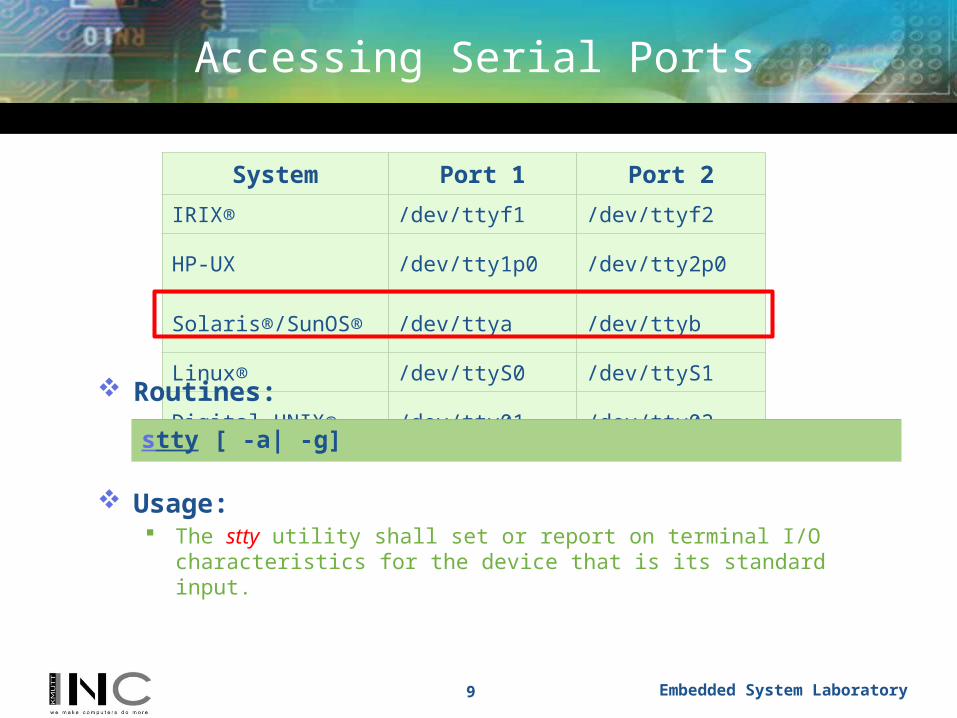
Accessing Serial Ports
9 Embedded System Laboratory
System Port 1 Port 2
IRIX® /dev/ttyf1 /dev/ttyf2
HP-UX /dev/tty1p0 /dev/tty2p0
Solaris®/SunOS® /dev/ttya /dev/ttyb
Linux® /dev/ttyS0 /dev/ttyS1
Digital UNIX® /dev/tty01 /dev/tty02 Routines:
Usage: The stty utility shall set or report on terminal I/O characteristics for the device
that is its standard input.
stty [ -a| -g]
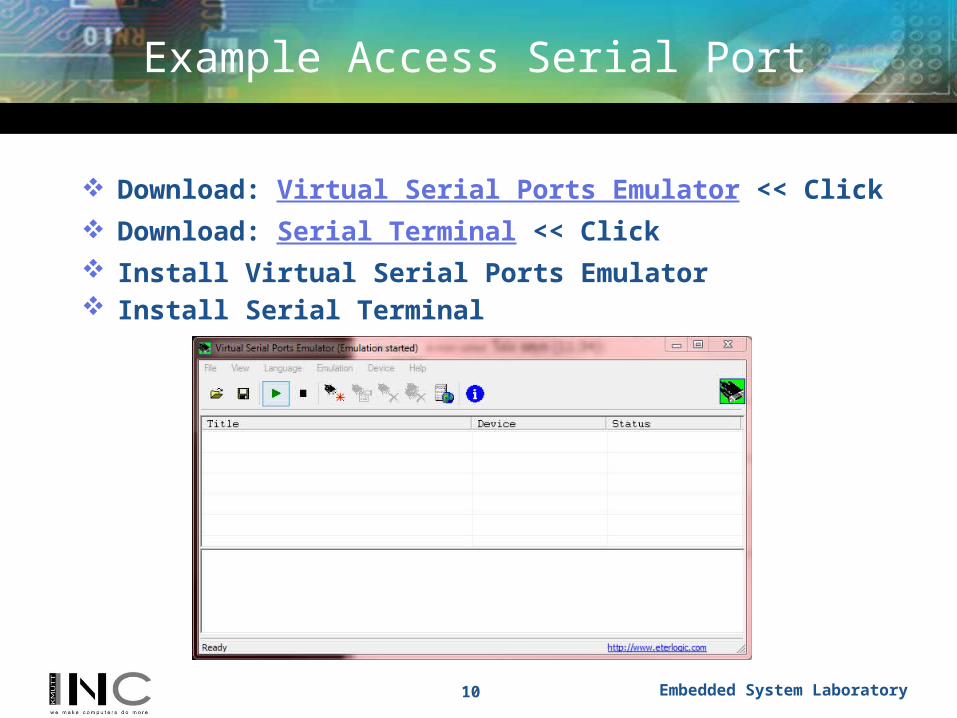
Example Access Serial Port
Download: Virtual Serial Ports Emulator << Click Download: Serial Terminal << Click Install Virtual Serial Ports Emulator Install Serial Terminal
10 Embedded System Laboratory

Example Access Serial Port (Cont.)
Click Create new device… Select Device type: pair Click Next Select your virtual serial port 1 and 2 Click Finish
11 Embedded System Laboratory

Example Access Serial Port (Cont.)
Open Vmware Click Edit virtual machine setting Add Serial Port Connection:
Use physical serial port
Select your virtual serial port
12 Embedded System Laboratory

Example Access Serial Port (Cont.)
Practice: A list of Serial Port name
Practice: Change baud rate to 38400
Practice: Enable parity bit
Practice: Print only one line containing string $
13 Embedded System Laboratory
root@slax:# dmesg | grep tty
root@slax:# stty –F /dev/ttyS0 38400
root@slax:# stty –F /dev/ttyS0 parenb
root@slax:# cat /dev/ttyS0 | grep $ -m 1

Contents
Basic of Serial Communications1
Configuring the Serial Port2
Advanced Serial Programming3
Appendix A, RS-232 Pinouts4
14 Embedded System Laboratory
Appendix B, ASCII Codes5
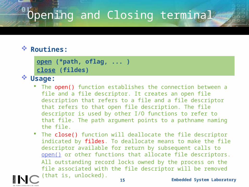
Opening and Closing terminal
Routines:
Usage: The open() function establishes the connection between a file and a file
descriptor. It creates an open file description that refers to a file and a file descriptor that refers to that open file description. The file descriptor is used by other I/O functions to refer to that file. The path argument points to a pathname naming the file.
The close() function will deallocate the file descriptor indicated by fildes. To deallocate means to make the file descriptor available for return by subsequent calls to open() or other functions that allocate file descriptors. All outstanding record locks owned by the process on the file associated with the file descriptor will be removed (that is, unlocked).
15 Embedded System Laboratory
open (*path, oflag, ... )close (fildes)

Getting and Setting terminal
Routines:
Usage: Most systems support the POSIX terminal (serial) interface for changing
parameters such as baud rate, character size, and so on. The first thing you need to do is include the file <termios.h>; this defines the terminal control structure as well as the POSIX control functions.
These get and set terminal attributes, respectively; you provide a pointer to a termios structure that contains all of the serial options available:
16 Embedded System Laboratory
tcgetattr (fildes, *termios_p) tcsetattr (fildes, optional_actions, *termios_p); cfgetispeed (*termios_p) cfsetispeed (*termios_p, speed_t) cfgetospeed (*termios_p) cfsetospeed (*termios_p, speed_t)

Reading and Writing terminal
Routines:
Usage: The read() function attempts to read nbyte bytes from the file associated with
the open file descriptor, fildes, into the buffer pointed to by buf. If nbyte is 0, read() will return 0 and have no other results. The write() function attempts to write nbyte bytes from the buffer pointed to
by buf to the file associated with the open file descriptor, fildes. If nbyte is 0, write() will return 0 and have no other results if the file is a
regular file; otherwise, the results are unspecified.
17 Embedded System Laboratory
read (fildes, *buf, nbyte) write (fildes, *buf, nbyte)

Example Configuring the Serial Port
Practice: vi serial.c
18 Embedded System Laboratory
#include <unistd.h>#include <sys/stat.h>#include <fcntl.h>#include <stdlib.h>#include <string.h>#include <stdio.h>#include <errno.h> #include <termios.h>
int main() { int port; int count = 0; char buf[] = "\r\nPlease press any key... in 10 sec\r\n"; struct termios tty_attributes;

Example Configuring the Serial Port
Practice: (Cont.)
19 Embedded System Laboratory
port = open("/dev/ttyS0", O_RDWR | O_NOCTTY | O_NONBLOCK); tcgetattr(port, &tty_attributes); tty_attributes.c_cflag = CS8 | CLOCAL | CREAD; tty_attributes.c_iflag = IGNPAR | IGNBRK; tty_attributes.c_oflag = 0;
cfsetospeed(&tty_attributes,B9600); // Set the baud rate cfsetispeed(&tty_attributes,B9600); tcflush(port, TCIOFLUSH); tcsetattr(port, TCSANOW, &tty_attributes); sleep(1);
write(port, buf, sizeof(buf)); sleep(10);

Example Configuring the Serial Port
Practice: (Cont.)
20 Embedded System Laboratory
while (read(port, &buf[count], 1) > 0) { count++; } buf[count++] = 0; printf("Your pressed key: %s\n", buf); write(port, buf, sizeof(char) * count);
close(port); exit(0);}

Contents
Basic of Serial Communications1
Configuring the Serial Port2
Advanced Serial Programming3
Appendix A, RS-232 Pinouts4
21 Embedded System Laboratory
Appendix B, ASCII Codes5

Advanced Serial Programming
Routines:
Usage: The ioctl() function performs a variety of control functions on STREAMS
devices. For non-STREAMS devices, the functions performed by this call are unspecified. The request argument and an optional third argument (with varying type) are passed to and interpreted by the appropriate part of the STREAM associated with fildes.
The fcntl() function provides for control over open files. The fildes argument is a file descriptor.
22 Embedded System Laboratory
Ioctl (fildes, request, ...) fcntl (fildes, cmd, ...)

Advanced Serial Programming
23 Embedded System Laboratory
Request Description POSIX Function
TCGETS Gets the current serial port settings. tcgetattr
TCSETS Sets the serial port settings immediately.
tcsetattr(fd, TCSANOW, &options)
TCSETSF Sets the serial port settings after flushing the input and output buffers.
tcsetattr(fd, TCSAFLUSH, &options)
TCSETSWSets the serial port settings after allowing the input and output buffers to drain/empty.
tcsetattr(fd, TCSADRAIN, &options)
TCSBRK Sends a break for the given time. tcsendbreak, tcdrain
TCXONC Controls software flow control. tcflow
TCFLSH Flushes the input and/or output queue. tcflush
TIOCMGET Returns the state of the "MODEM" bits. None
TIOCMSET Sets the state of the "MODEM" bits. None
FIONREAD Returns the number of bytes in the input buffer. None

Example Advance Serial Programming
Practice: vi interface.c
24 Embedded System Laboratory
#include <termios.h>#include <stdio.h>#include <unistd.h>#include <fcntl.h>#include <sys/signal.h>#include <sys/types.h>
#define BAUDRATE B38400#define FALSE 0#define TRUE 1
volatile int STOP=FALSE;
void signal_handler_IO (int status); int wait_flag=TRUE; FILE *input;FILE *output;int status;
Example Advance Serial Programming
Practice: (Cont.)
25 Embedded System Laboratory
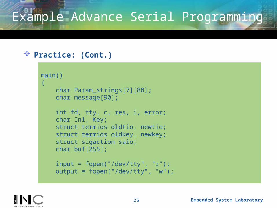
main(){ char Param_strings[7][80]; char message[90];
int fd, tty, c, res, i, error; char In1, Key; struct termios oldtio, newtio; struct termios oldkey, newkey; struct sigaction saio; char buf[255];
input = fopen("/dev/tty", "r"); output = fopen("/dev/tty", "w");

Example Advance Serial Programming
Practice: (Cont.)
26 Embedded System Laboratory
tty = open("/dev/tty", O_RDWR | O_NOCTTY | O_NONBLOCK); tcgetattr(tty,&oldkey); newkey.c_cflag = BAUDRATE | CRTSCTS | CS8 | CLOCAL | CREAD; newkey.c_iflag = IGNPAR; newkey.c_oflag = 0; newkey.c_lflag = 0; //ICANON; newkey.c_cc[VMIN] = 1; newkey.c_cc[VTIME] = 0; tcflush(tty, TCIFLUSH); tcsetattr(tty,TCSANOW,&newkey); fd = open("/dev/ttyS0", O_RDWR | O_NOCTTY | O_NONBLOCK);

Example Advance Serial Programming
Practice: (Cont.)
27 Embedded System Laboratory
//install the serial handler before making the device asynchronous saio.sa_handler = signal_handler_IO; sigemptyset(&saio.sa_mask); //saio.sa_mask = 0; saio.sa_flags = 0; saio.sa_restorer = NULL; sigaction(SIGIO,&saio,NULL);
// allow the process to receive SIGIO fcntl(fd, F_SETOWN, getpid()); // Make the file descriptor asynchronous (the manual page says only // O_APPEND and O_NONBLOCK, will work with F_SETFL...) fcntl(fd, F_SETFL, FASYNC);
tcgetattr(fd, &oldtio); // save current port settings // set new port settings for canonical input processing
Example Advance Serial Programming
Practice: (Cont.)
28 Embedded System Laboratory
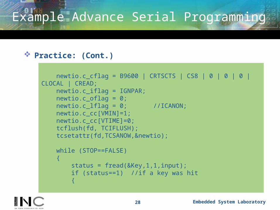
newtio.c_cflag = B9600 | CRTSCTS | CS8 | 0 | 0 | 0 | CLOCAL | CREAD; newtio.c_iflag = IGNPAR; newtio.c_oflag = 0; newtio.c_lflag = 0; //ICANON; newtio.c_cc[VMIN]=1; newtio.c_cc[VTIME]=0; tcflush(fd, TCIFLUSH); tcsetattr(fd,TCSANOW,&newtio);
while (STOP==FALSE) { status = fread(&Key,1,1,input); if (status==1) //if a key was hit {

Example Advance Serial Programming
Practice: (Cont.)
29 Embedded System Laboratory
switch (Key) {
case 0x1b: /* Esc */ STOP=TRUE;break;default: fputc((int) Key,output); write(fd,&Key,1);break;
} } if (wait_flag==FALSE) { res = read(fd,buf,255);

Example Advance Serial Programming
Practice: (Cont.)
30 Embedded System Laboratory
if (res>0) { printf("%s\n", buf); } wait_flag = TRUE; }
}
tcsetattr(fd,TCSANOW,&oldtio); tcsetattr(tty,TCSANOW,&oldkey); close(tty); close(fd);
Example Advance Serial Programming
Practice: (Cont.)
31 Embedded System Laboratory
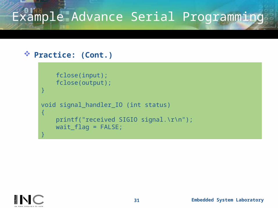
fclose(input); fclose(output);}
void signal_handler_IO (int status){ printf("received SIGIO signal.\r\n"); wait_flag = FALSE;}

Contents
Basic of Serial Communications1
Configuring the Serial Port2
Advanced Serial Programming3
Appendix A, RS-232 Pinouts4
32 Embedded System Laboratory
Appendix B, ASCII Codes5

RS-232 Pinouts RS-232 uses a 9-pin D-Sub connector
Appendix A, RS-232 Pinouts
33 Embedded System Laboratory
Pin Description Pin Description
1 DCD - Data Carrier Detect 6 Data Set Ready
2 RXD - Received Data 7 RTS - Request To Send
3 TXD - Transmitted Data 8 CTS - Clear To Send
4 DTR - Data Terminal Ready 9 Ring Detect
5 GND - Logic Ground

RS-232 Pinouts RS-232 comes in three flavors (A, B, C) and uses a 25-pin D-Sub connector:
Appendix A, RS-232 Pinouts
34 Embedded System Laboratory
Pin Description Pin Description
1 Earth Ground 14 Secondary TXD
2 TXD - Transmitted Data 15 Transmit Clock
3 RXD - Received Data 16 Secondary RXD
4 RTS - Request To Send 17 Receiver Clock
5 CTS - Clear To Send 18 Unassigned
6 DSR - Data Set Ready 19 Secondary RTS
7 GND - Logic Ground 20 DTR - Data Terminal Ready
8 DCD - Data Carrier Detect 21 Signal Quality Detect
9 Reserved 22 Ring Detect
10 Reserved 23 Data Rate Select
11 Unassigned 24 Transmit Clock
12 Secondary DCD 25 Unassigned
13 Secondary CTS

RS-422 Pinouts RS-422 also uses a 25-pin D-Sub connector, but with differential signals:
Appendix A, RS-232 Pinouts
35 Embedded System Laboratory
Pin Description Pin Description
1 Earth Ground 14 TXD+
2 TXD- - Transmitted Data 15 Transmit Clock-
3 RXD- - Received Data 16 RXD+
4 RTS- - Request To Send 17 Receiver Clock-
5 CTS- - Clear To Send 18 Unassigned
6 DSR - Data Set Ready 19 RTS+
7 GND - Logic Ground 20 DTR- - Data Terminal Ready
8 DCD- - Data Carrier Detect 21 Signal Quality Detect
9 Reserved 22 Unassigned
10 Reserved 23 DTR+
11 Unassigned 24 Transmit Clock+
12 DCD+ 25 Receiver Clock+
13 CTS+

Contents
Basic of Serial Communications1
Configuring the Serial Port2
Advanced Serial Programming3
Appendix A, RS-232 Pinouts4
36 Embedded System Laboratory
Appendix B, ASCII Codes5

Appendix B, ASCII Codes
37 Embedded System Laboratory
Most Significant Character
LeastSignificantCharacter
Hex 0 1 2 3 4 5 6 7
0 NUL DLE Space 0 @ P ` p
1 SOH DC1 ! 1 A Q a q
2 STX DC2 " 2 B R b r
3 ETX DC3 # 3 C S c s
4 EOT DC4 $ 4 D T d t
5 ENQ NAK % 5 E U e u
6 ACK SYN & 6 F V f v
7 Bell ETB ' 7 G W g w
8 BS CAN ( 8 H X h x
9 HT EM ) 9 I Y i y
A LF SUB * : J Z j z
B VT ESC + ; K [ k {
C FF FS , < L \ l |
D CR GS - = M ] m }
E SO RS . > N ^ n ~
F SI US / ? O _ o DEL

Appendix B, ASCII Codes (Cont.)
38 Embedded System Laboratory