Software Configuration - RobotShop...Lynxmotion UAV MultiWii Software Configuration B: Serial Port...
23
Lynxmotion UAV MultiWii Software Configuration Software Configuration FLIP (MultiWii compatible flight controller) Revision 1.0 Feb 17, 2014 BETA 1
Transcript of Software Configuration - RobotShop...Lynxmotion UAV MultiWii Software Configuration B: Serial Port...

Lynxmotion UAV MultiWii Software Configuration
Software ConfigurationFLIP (MultiWii compatible flight controller)
Revision 1.0 Feb 17, 2014 BETA
1

Lynxmotion UAV MultiWii Software Configuration
Table of Contents
Table of ContentsIntroductionSTEP 1: Preparation
A: MultiWii Board Drivers (For FLIP Flight Controller)B: Download / Install Arduino IDE SoftwareC: Download / Install JAVAD: MultiWii Files
STEP 2: MultiWii CodeSTEP 3: Arduino Board Setup
A: Board SelectionB: Serial Port SelectionC: Upload to the Board
STEP 4: MultiWii GUI Configuration ToolSTEP 5: End Point CalibrationSTEP 6: Load Configuration FileAppendix 1: Configure MultiWii (Advanced users)Appendix 2: Using the MultiWii GUI (Optional)
Introduction
The FLIP MultiWii compatible flight controller is one of the least expensive multirotor flight controllers on themarket. Alexandre Dubus started the MultiWii project many years ago, originally using an Arduinomicrocontroller linked to a Nintendo Wii gyroscope (already present in the remote) to control multirotoraircraft, which is where the name “MultiWii” came from. It quickly became more and more popular and hissoftware was adapted to work with a wide variety of sensors. Today the “MultiWii” project is a very powerfulopen source software that keeps getting better with each revision release and is compatible with a variety ofoff the shelf flight controllers and sensors. This document is intended to help you get started using the FLIP(MultiWii compatible) flight controller as part of Lynxmotion multirotor UAV kits.
2

Lynxmotion UAV MultiWii Software Configuration
STEP 1: Preparation
A: MultiWii Board Drivers (For FLIP Flight Controller)
http://www.silabs.com/products/mcu/pages/usbtouartbridgevcpdrivers.aspx
In order to communicate with the MultiWii board, you must download and install the correct USB toserial drivers (VCP = Virtual Com Port). This allows your computer to recognize and communicatewith the FLIP when it’s connected to the computer. Visit the site above and choose the downloadwhich corresponds to your operating system (“Download for ….”). After extracting the ZIP file, installit on your system using the .exe file.
B: Download / Install Arduino IDE Software
http://arduino.cc/en/main/software
The MultiWii program was created using the Arduino software. We suggest that you have the latestversion installed on your system. Go to www.Arduino.cc and click the "Download" tab at the top ofthe page. Scroll down and you will see a section "Arduino IDE" and Download". Choose the linkwhich corresponds to whichever operating system you are running on your computer (Windows,Mac, Linux etc) and download the software to a known location on your computer.
We suggest extracting the main “Arduino” folder to a new folder under c: drive. We tend to put itunder "Program Files". Once extracted, you can go to that folder on your computer and see an iconmarked "Arduino.exe". This starts the Arduino program (you may want to create a shortcut on yourdesktop too). You can double click this to see that it works, then close it.
Arduino software interface
3

Lynxmotion UAV MultiWii Software Configuration
C: Download / Install JAVA
https://www.java.com/en/
If you do not already have the latest version of Java, go to www.java.com and click the “FreeDownload”. It should automatically detect your system and provide the correct download file. Followthe instructions for the installation. JAVA is used for the MultiWii General User Interface (GUI).Note: If the GUI interface is not opening correctly, refer back to the JAVA installation in step 1.
D: MultiWii Files
Download the preconfigured MultiWii file your Lynxmotion UAV / Drone platform below. These fileshave been configured specifically for the FLIP flight controller and copter type.
http://www.lynxmotion.com/s4electronicsguides.aspx#UAV
Extract these files to a known location on your computer. We suggest placing them under the“examples” folder you created in step C. This way the MultiWii project will be available under the“Examples” tab within the IDE software. EX: C:Program Files/Arduino/examples/
Advanced users can also download the latest stable version of MultiWii. Do not download a “dev”version which is intended for developers or advanced users and are often in BETA state. Note thatthere are many tabs, many of which need to be modified slightly for a specific setup (ex. choosing acontroller type, copter type etc.).
https://code.google.com/p/multiwii/downloads/list
4

Lynxmotion UAV MultiWii Software Configuration
STEP 2: MultiWii Code
Connect the MultiWii board to the computer using the appropriate USB cable. Your computer should detectand identify the board since you already installed the drivers.
A. If you unzipped the file to the Arduino examples folder.1. Start the Arduino program by doubleclicking “Arduino.exe”2. At the top left of the screen, go to “File > Examples > MultiWii_X_X > MultiWii”3. Within the Arduino software, you should see several tabs appear on top, the first of which is
called "MultiWii"
B. If you unzipped the file to another location.1. Open the file location for Arduino created in step B.2. Start the Arduino program by doubleclicking “Arduino.exe”3. At the top left of the screen, go to “File > Open”4. Browse to the MultiWii file folder on your computer5. Within that folder you will find a file “MultiWii.ino”6. Select that file and click "open"7. Within the Arduino software, you should see several tabs appear on top, the first of which is
called "MultiWii"
MultiWii Program in Arduino Software
5

Lynxmotion UAV MultiWii Software Configuration
STEP 3: Arduino Board Setup
The next step is to select your MultiWii board and COM port so the Arduino software will know which boardit is communicating with and via which COM port so you can upload the file.
A: Board SelectionTell the Arduino software which board you're using. Under “Tools > Board” and select the rightboard. For the Flip MultiWii Flight Controller, select the “Arduino Pro / Pro Mini (5V, 16Mhz)w/ATMega328”.
Arduino Software Board Selection
6

Lynxmotion UAV MultiWii Software Configuration
B: Serial Port SelectionUnder “Tools > Serial Port”, select the right Serial Port > COM XX (The number is different for eachcomputer). If you don't know which COM port is connected to the board, unplug the board, look atthe selection of COM ports available, then plug the board back in; a new COM port should appearand this is the one you need to select.
Arduino Software COM port selection
WARNING Be sure to have the main battery removed when you upload code as there is a risk that the motors
may start spinning by accident.
7
Lynxmotion UAV MultiWii Software Configuration
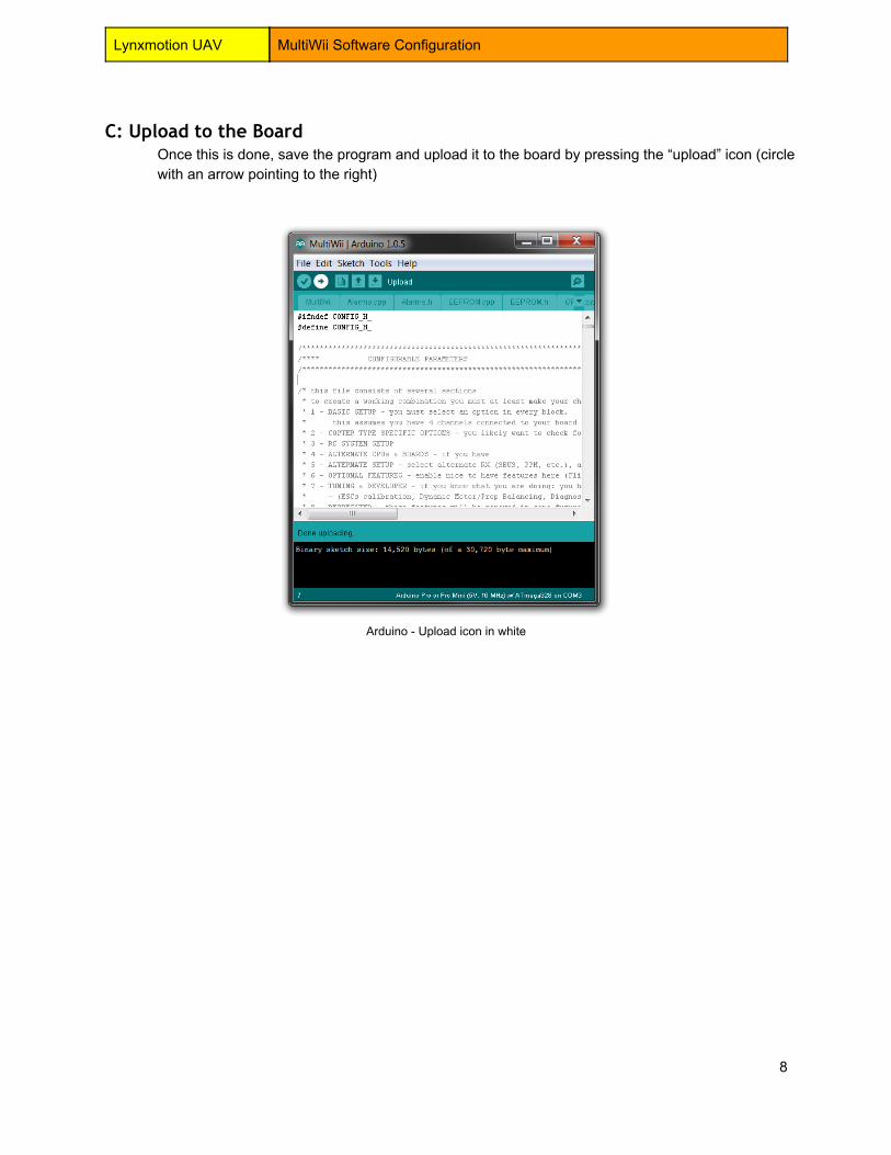
C: Upload to the BoardOnce this is done, save the program and upload it to the board by pressing the “upload” icon (circlewith an arrow pointing to the right)
Arduino Upload icon in white
8
Lynxmotion UAV MultiWii Software Configuration
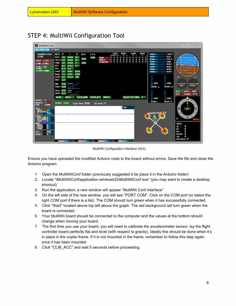
STEP 4: MultiWii Configuration Tool
MultiWii Configuration Interface (GUI)
Ensure you have uploaded the modified Arduino code to the board without errors. Save the file and close theArduino program.
1. Open the MultiWiiConf folder (previously suggested it be place it in the Arduino folder)2. Locate “\MultiWiiConf\application.windows32\MultiWiiConf.exe” (you may want to create a desktop
shortcut)3. Run the application; a new window will appear “MultiWii Conf Interface”4. On the left side of the new window, you will see “PORT COM”. Click on the COM port (or select the
right COM port if there is a list). The COM should turn green when it has successfully connected.5. Click "Start" located above top left above the graph. The red background will turn green when the
board is connected.6. Your MultiWii board should be connected to the computer and the values at the bottom should
change when moving your board.7. The first time you use your board, you will need to calibrate the accelerometer sensor: lay the flight
controller board perfectly flat and level (with respect to gravity). Ideally this should be done when it’sin place in the copter frame. If it is not mounted in the frame, remember to follow this step againonce it has been mounted.
8. Click "CLIB_ACC" and wait 5 seconds before proceeding.
9

Lynxmotion UAV MultiWii Software Configuration
STEP 5: End Point Calibration
WARNING The following setup should be done without the propellers installed on your copter. Moving the joysticks
around could cause it to become “Armed” causing the motors to spin.
In order to work correctly, the FLIP flight controller needs you to configure your transmitter’s “End Points”.End Points are the maximum and minimum signal values which your transmitter sends when the joystick(s)reach their mechanical limits. Unfortunately the min/max values on most controllers are not high enough tobe used by the FLIP controller and need to be set higher than the default settings. Note that not all flightcontrollers have the option to increase or decrease End Points; if you have chosen a remote control whichdoes not allow these settings to be modified, you will need to refer to the MultiWii online guide. For flightcontrollers which allow the End Points to be reconfigured, follow the procedure below:
1. Power your handheld transmitter and turn it on2. Connect your main battery (Should power up the Flight Controller and Receiver)3. Connect your Flight Controller to the PC with the USB cable4. Open the MultiWiiConf.exe application5. Make sure your subtrims are all centered and show values of 1500. If not, you can move them until
you reach that number.6. For each of your channels you have to set up the End Point so it shows 1000 as the minimum value
and 2000 at maximum (usually 120% on the transmitter)
STEP 6: Load Configuration File
PID settings need to be changed for your copter to react right. This is done mostly by trial and error of thesettings. We have some PreConfigured files for our platform that are included in the MultiWii zip youdownloaded earlier. If you want to do it yourself, please refer to MultiWii PID Wiki
1. In the MultiwiiConf GUI interface, click on the “LOAD” button and browse to the desired file. It shouldhave an .mwi extension. Once selected click “Open”.
2. You will see a message box saying “Configuration loaded: example.mwi”. Click “OK”3. Parameters should be loaded to the GUI, Click “WRITE” to send it to the board.
Note: This does not save the AUX settings.
You can now proceed with the electronics guide.
10
Lynxmotion UAV MultiWii Software Configuration
Appendix 1: Configure MultiWii (Advanced users)
Important Note: If you want to better understand the configuration needed in order to get the “general”MultiWii code configured for your specific copter type, a few of the major changes are outlined below.However, if you chose one of the preconfigured programs in step 1d, then you can skip to step 4c.
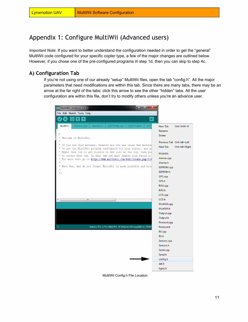
A) Configuration TabIf you’re not using one of our already “setup” MultiWii files, open the tab “config.h”. All the majorparameters that need modifications are within this tab. Since there are many tabs, there may be anarrow at the far right of the tabs; click this arrow to see the other “hidden” tabs. All the userconfiguration are within this file, don’t try to modify others unless you're an advance user.
MultiWii Config.h File Location
11

Lynxmotion UAV MultiWii Software Configuration
B) Changing ParametersIf you’re not using one of our preconfigured MultiWii files, you might have to change someparameters which are specific to your board, copter and/or hardware.
A. Copter TypeTo tell the software which copter type you will be using the board for. Find (****The Type ofmulticopter****) and under that uncomment the type of copter you have. ex: Quad, HEX6 orany others. To uncomment, remove the two forward slashes at the start of the line, the linewill turn from gray to black telling you it’s defined.
B. MultiWii Board/SensorsBecause MultiWii support many different board, you need to tell the software board you willbe using. Find (****Combined IMU Boards****) and uncomment your board. If you're usingthe FLIP MultiWii board the define will be #define FLYDUINO_MPU (towards the bottom ofthe list)
C. Throttle when ArmedNot all ESC’s react the same so you might have to play with this value to get the motors tospin at a slow rate when you arm the board. Find (****Motor minthrottle****) and define yourESC and if he is not in the list, only change the number. This is a try and test procedureuntil you have it where you want.
12

Lynxmotion UAV MultiWii Software Configuration
Appendix 2: Using the MultiWii GUI (Optional)
At this point, you can proceed to the electrical wiring. If you want to learn more about MultiWii you cancontinue with the rest of this guide.
Software versionThis give you which version is uploaded to yourMultiWii flight controller.
Save / Load configurationEnable you to save your PID and Setup settings to afile to be able to load it again later. Useful if you useyour Flight Controller on multiple platform.
COM Port SelectionHere you will have to select the COM port of yourFlight Controller before being able to start acommunication.
PID SettingsThese settings will determine how much of acompensation the flight controller will produce. Tochange them you have to maintain the click in thegreen square and move your mouse left or right tochange the value. Once set, click on WRITE to sendit to the Controller.MultiWii PID
Flight Mode / AUXHere are all the available flight mode that can beactivated from an AUX switch if needed. Only theMode’s that are compatible with your flight controllerwill show here.
13

Lynxmotion UAV MultiWii Software Configuration
RC Transmitter ValuesHere you can see the value of each channelconnected to your MultiWii board in real time.It’suseful to setup your transmitter to output all signalsbetween 10002000.
ESC ValuesThese are the output values sent to eachESC/Motors of your copter. Once armed, thesevalues should go up to to the ****Motorminthrottle**** value as found in Confi.h when youthrottle up.
Model 3D DisplayThis provides a visual (3D) representation of thequadcopter’s orientation. Note that the defaultorientation is at a slight angle.
Included in this diagram are which motors to connectto which pins on the MultiWii board. The red arrowsshow you the orientation / direction of the propellers.
HorizonJust as in a regular aircraft, a horizon shows you ifthe aircraft is pitched forward or backward or isrolling left or right. The blue represents “sky” andbrown represents “ground”. If your think your board ishorizontal and the horizon is not level, your sensorsneed to be recalibrated.
14

Lynxmotion UAV MultiWii Software Configuration
Compass / Additional SensorsThe FLIP / MultiWii board only contains anaccelerometer and a gyroscope. You can add anexternal pressure sensor (altimeter), GPS andmagnetic compass. Other compatible boards mayhave this functionality onboard. You would get thereadings for each here.
MultiWii Exponential & RateThis section if mostly used by experienced UAVpilots. It gives the user curves of the Throttle andPitch/Roll.
MultiWii Read/Write bar
READ: Reads the settings that are already loaded on the board RESET: Clears all the change you might have done if you didn’t click “WRITE” CALIB_MAG: Starts the Magnetometer calibration CALIB_ACC: Starts the Accelerometer calibration WRITE: Writes (uploads) the settings to the board SELECT SETTING: Experimental option (Don’t use unless you know what it is)
15

Lynxmotion UAV MultiWii Software Configuration
MultiWii Sensors value and Graph
This in important window; it’s the graph which shows you in real time the raw value of the sensors youhave on your board.
ACC (Accelerometer)
ROLL Accelerometer value for the Roll (~wing angle) axis
PITCH Accelerometer value for the Pitch (nose up/down) axis
Z Accelerometer value for the Z (vertical) axis
GYRO (Gyroscope)
ROLL Gyroscope value for the Roll axis
PITCH Gyroscope value for the Pitch axis
YAW Gyroscope value for the Yaw axis
MAG (Magnetometer)
ROLL Magnetometer value for the Roll axis
PITCH Magnetometer value for the Pitch axis
YAW Magnetometer value for the Yaw (direction) axis
ALT (Altitude) Altitude based on the Barometer
HEAD (Heading) Heading based on the Magnetometer
Table of sensors value showed in the GUI (with colors)
16

Lynxmotion UAV MultiWii Software Configuration
Troubleshooting Using Sensor ValuesThis approach helps to troubleshoot if you have directional issue with your copter. It will show you if theboard is mounted in the right orientation or if you have not selected the right board in the “config.h”
TILT the MULTI to the RIGHT (left side up):MAG_ROLL, ACC_ROLL and GYRO_ROLL goes upMAG_Z and ACC_Z goes down
TILT the MULTI forward (tail up):MAG_PITCH, ACC_PITCH and GYRO_PITCH goes upMAG_Z and ACC_Z goes down
Rotating the copter clockwise (YAW):GYRO_YAW goes up
The copter stays level:MAG_Z is positive ; ACC_Z is positive
Flight ModesA number of flight modes are defined and can be assigned to transmitter AUX switches in the MultiWiiConfGUI. If you have a transmitter with five or more channels you can configure the software to allow you tochange the flight mode via the 5th channel (aux switch). Each mode is defined below.
Mode Gyroscope Accelerometer Barometer Compass(Mag)
GPS
ACRO / Gyro Only X
ANGLE (Stable/Level/Acc) X X
HORIZON X X
BARO (Altitude Hold) X X X
MAG (Heading Hold) X X X
HEADFREE (CareFree) X X X
GPS Return to Home X X X X
GPS Waypoint X X X X
GPS Position Hold X X X X
Failsafe X
Flight modes showing hardware required
X = Required Hardware for the Mode
17
Lynxmotion UAV MultiWii Software Configuration
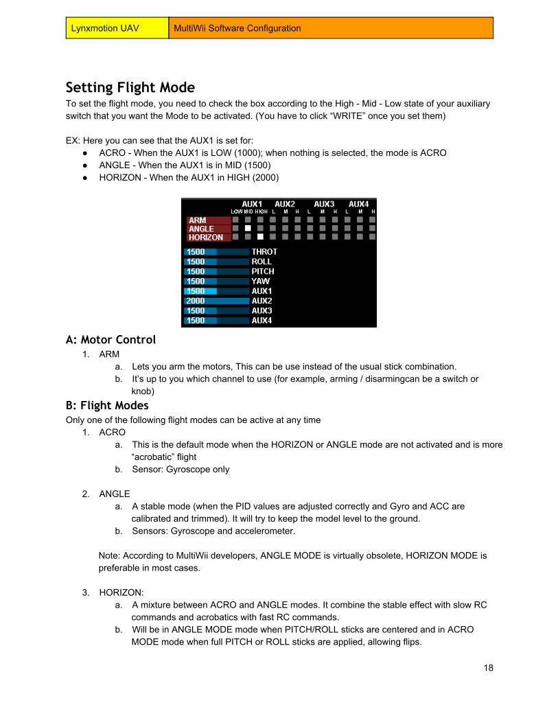
Setting Flight ModeTo set the flight mode, you need to check the box according to the High Mid Low state of your auxiliaryswitch that you want the Mode to be activated. (You have to click “WRITE” once you set them)
EX: Here you can see that the AUX1 is set for: ACRO When the AUX1 is LOW (1000); when nothing is selected, the mode is ACRO ANGLE When the AUX1 is in MID (1500) HORIZON When the AUX1 in HIGH (2000)
A: Motor Control1. ARM
a. Lets you arm the motors, This can be use instead of the usual stick combination.b. It’s up to you which channel to use (for example, arming / disarmingcan be a switch or
knob)B: Flight ModesOnly one of the following flight modes can be active at any time
1. ACROa. This is the default mode when the HORIZON or ANGLE mode are not activated and is more
“acrobatic” flightb. Sensor: Gyroscope only
2. ANGLEa. A stable mode (when the PID values are adjusted correctly and Gyro and ACC are
calibrated and trimmed). It will try to keep the model level to the ground.b. Sensors: Gyroscope and accelerometer.
Note: According to MultiWii developers, ANGLE MODE is virtually obsolete, HORIZON MODE ispreferable in most cases.
3. HORIZON:a. A mixture between ACRO and ANGLE modes. It combine the stable effect with slow RC
commands and acrobatics with fast RC commands.b. Will be in ANGLE MODE mode when PITCH/ROLL sticks are centered and in ACRO
MODE mode when full PITCH or ROLL sticks are applied, allowing flips.
18

Lynxmotion UAV MultiWii Software Configuration
c. Sensors: Gyroscope and Accelerometer.
Additional flight modes which can be activated in combination with the main flight modes and each other:
4. BAROa. The barometer is used in order to keep a certain (fixed) height when no other commands
from the RC transmitter are received.b. If you activate BARO (ALT HOLD) and the GPS modes, they will use the same calculated
altitude.c. Sensors: Gyroscope, Accelerometer and Barometer (Accelerometer is needed to estimate
the Z acceleration in this mode) You can activate BARO (ALT HOLD) and the GPS modeswill use the same altitude.
5. MAGa. Heading (compass direction) lock mode, it will try to keep its Yaw orientation. This can be
activated in all flight stabilization modes. The UAV will keep pointing in the same directionuntil there is a yaw input from the transmitter. Without this mode, you will still have slightdeviation (like a tail gyro in heli). Compared to no MAG, this mode offers a drift free tail, justlike the difference between heading hold and conventional helicopter gyros.
b. Sensors: Gyroscope, Accelerometer and Magnetometer (Accelerometer is needed alsobecause it is used in heading angle determination)
6. HEADFREEa. Does not impact the flight mode (ANGLE/HORIZON/ACRO). It only holds the orientation
(yaw) of the multi and will always move in the same 2D direction for the same ROLL/PITCHstick movement. Can be activated with MAG mode.
b. Holds the pilots 2D perspective as reference, MAG does not, both give a drift free tail.
7. HEADADJa. Sets a new yaw origin for HEADFREE mode.
C: GPS Modes
GPS modes can be activated in ANGLE or HORIZON flight modes. will be ignored if there is no GPS lock attime of arming. are generally used along with ALT HOLD, but this is not mandatory.the mag sensor is mandatory for GPS control, but MAG mode is not. Activation of MAG MODE has noeffect in GPS MODE. GPS altitude is never used in a control loop (only for display).
1. GPS HOMEa. Uses compass and GPS for the purpose of returning home to the starting point.
Stabilisation is done in accordance with the flight mode (ANGLE/HORIZON). The GPSaltitude is not very accurate and therefore not usable for holding the height.
2. GPS HOLDa. Hold current position using GPS and baro (if available).
19
Lynxmotion UAV MultiWii Software Configuration
VTail alternate MixingsMany user don’t like the way MultWii is mixing the special tail configuration of the VTail. So they changethose mixing to something more optimal. It is greatly suggested to do it but it require to change the codeslightly prior to upload.
Those will change the mixing output to the motors and should give a more natural behaviour for the copter.Our presetup files already have those changes done in the NewVTail.h file that is define in the config.h withthis line (#define MY_PRIVATE_MIXING "NewVTail.h")
If you want to start from scratch, here is how to do it.You need to find this line in the Output.ccp tab:
#elif defined( VTAIL4 )motor[0] = PIDMIX(+0,+1, +1); //REAR_Rmotor[1] = PIDMIX(1, 1, +0); //FRONT_Rmotor[2] = PIDMIX(+0,+1, 1); //REAR_Lmotor[3] = PIDMIX(+1, 1, 0); //FRONT_L
And replace it with one of those tested mix.
#elif defined( VTAIL4 )// Kipkool VTail's mixing motor[0] = PIDMIX(+0,+1, +1); //REAR_Rmotor[1] = PIDMIX(1, 1, 0.64); //FRONT_Rmotor[2] = PIDMIX(+0,+1, 1); //REAR_Lmotor[3] = PIDMIX(+1, 1, +0.64); //FRONT_L
#elif defined( VTAIL4 )// BrandXPD VTail 400/500 mixing motor[0] = PIDMIX(.50,+.93,+1);//REAR_Rmotor[1] = PIDMIX(.77,.50,.91); //FRONT_Rmotor[2] = PIDMIX(+.50,+.93,1); //REAR_Lmotor[3] = PIDMIX(+.77,.50,+.91); //FRONT_L
#elif defined( VTAIL4 )// BrandXPD MiniVTail mixing motor[0] = PIDMIX(.44,+.84,+1);//REAR_Rmotor[1] = PIDMIX(.75,.44,.81); //FRONT_Rmotor[2] = PIDMIX(+.44,+.84,1);//REAR_Lmotor[3] = PIDMIX(+.77,.44,+.81); //FRONT_L
Note: You can also define custom mixing table for odd shape copters.http://www.multiwii.com/wiki/index.php?title=Config.h#Individual_Mixing
20

Lynxmotion UAV MultiWii Software Configuration
MultiWii Stick Configuration (For Mode 2 Transmitter)
21
Lynxmotion UAV MultiWii Software Configuration
Alternate ESC CalibrationThere is a function in MultiWii to calibrate each ESC at the same time. This is done in config.h and needyou to upload a Not Flyable version that will calibrate all your ESC’s and then upload back the rightversion after. Be very careful with this procedure because it can cause the propeller to spin in someoccasions.
WARNING Remove your propellers from the motors prior to do this.
1. Remove all propellers.2. You have to upload a Non Flyable version of MultiWii to your board. Once done, the Flight
Controller will itself do the calibration at power up. After calibration the real MultiWii version will needto be reuploaded.
3. Go in the MultiWii “config.h” tab and find “//#define ESC_CALIB_CANNOT_FLY”. If you don’t find it.Click on the “Edit” menu on top and then “Find….”. Search for “//#defineESC_CALIB_CANNOT_FLY”.
4. Edit this line to remove the double dash before it like that “#define ESC_CALIB_CANNOT_FLY”.5. Upload this to your board.6. Power your copter, the board will run the calibration and you will hear the motors sound telling you
it’s doing the calibration also you will see the LED on the Flight Controller telling you it’s finished(After about 10 seconds).
7. ReEdit the line to add back the two dash “//#define ESC_CALIB_CANNOT_FLY” and Upload.8. The calibration is done.
Note: If necessary, the low and high values for the ESCs can be tweaked by changing the values for thedefines of ESC_CALIB_LOW and ESC_CALIB_HIGH 2000. Do this only if you know what you're doing.
22

Lynxmotion UAV MultiWii Software Configuration
Useful Links
Alternate GUI Interfacehttp://code.google.com/p/mwwingui/https://chrome.google.com/webstore/detail/baseflightconfigurator/mppkgnedeapfejgfimkdoninnofofigk?utm_source=gmailhttps://play.google.com/store/apps/details?id=com.ezio.multiwiihttps://play.google.com/store/apps/details?id=net.xrotor.andmultiwiiconf
Config.h Informationhttp://www.multiwii.com/wiki/index.php?title=Config.h
Config.h Online ConfiguratorFor MultiWii 2.2 and before onlyhttp://panoramaic.se/configurator/
PID Tuninghttp://www.multiwii.com/wiki/index.php?title=PID
MultiWii Official Wikihttp://www.multiwii.com/wiki
23