
EMA 3702 Mechanics & Materials Science (Mechanics of ... · w M x wx wLx 2 1 2 1 M x( ) wx R 2x D 2...
24
EMA 3702 Mechanics & Materials Science (Mechanics of Materials) Chapter 9 Deflection of Beams
Transcript of EMA 3702 Mechanics & Materials Science (Mechanics of ... · w M x wx wLx 2 1 2 1 M x( ) wx R 2x D 2...

EMA 3702
Mechanics & Materials Science
(Mechanics of Materials)
Chapter 9 Deflection of Beams

Introduction • Beams will deform under load, and the extent of
deformation, especially the transverse deformation or
displacement is of great interest for structure design, and
the transverse displacement is named “deflection”
• Goal: understand deformation/deflection under transverse
loading/bending moment and design appropriately

Deformation under Transverse Loading (1)
For bending of beam with moment
M, bending curvature (Chapter 4)
E Elastic modulus
I Moment of inertia
M Bending moment
Generally, M = M (x), therefore,
On the other hand, when and y and
dy/dx are very small, mathematically:
Therefore,
dx
dx
dyd
dx
yd
x
)(
)(
12
2
EI
xM
dx
yd )(2
2
1
𝜌=𝑀
𝐸𝐼
1
𝜌(𝑥)=𝑀(𝑥)
𝐸𝐼

Governing differential equation for
transverse deflection of a beam, i.e., for the
y(x) curve, also known as the “elastic curve”
EI Flexural rigidity
Deformation under Transverse Loading (2)
EI
xM
dx
yd )(2
2
Integrate the differential
equation in x, we have
Define as the angle
between elastic curve local
tangent and x axis
tandx
dywhen y
very small
in radian
𝐸𝐼𝑑𝑦
𝑑𝑥= න
0
𝑥
𝑀 𝑥 𝑑𝑥 + 𝐶1
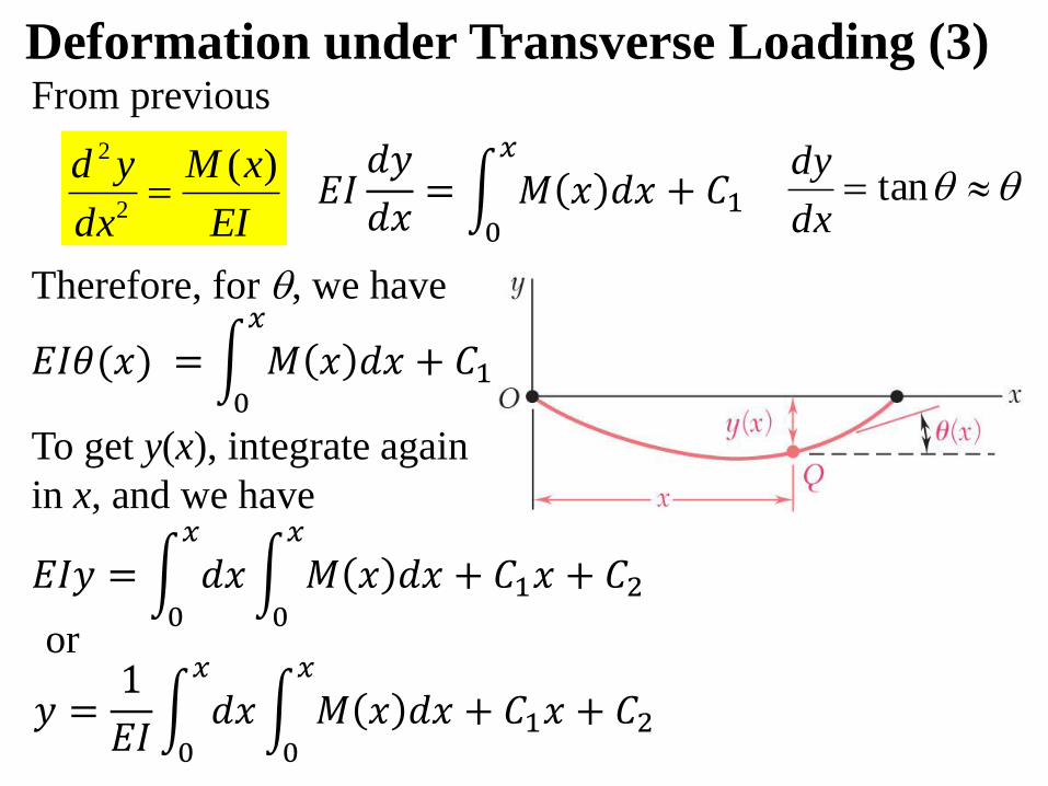
Therefore, for , we have
Deformation under Transverse Loading (3)
EI
xM
dx
yd )(2
2
tandx
dy
From previous
To get y(x), integrate again
in x, and we have
or
𝐸𝐼𝑑𝑦
𝑑𝑥= න
0
𝑥
𝑀 𝑥 𝑑𝑥 + 𝐶1
𝐸𝐼𝜃(𝑥) = න0
𝑥
𝑀 𝑥 𝑑𝑥 + 𝐶1
𝐸𝐼𝑦 = න0
𝑥
𝑑𝑥න0
𝑥
𝑀 𝑥 𝑑𝑥 + 𝐶1𝑥 + 𝐶2
𝑦 =1
𝐸𝐼න0
𝑥
𝑑𝑥න0
𝑥
𝑀 𝑥 𝑑𝑥 + 𝐶1𝑥 + 𝐶2

C1 & C2 are integration
constants and could be
determined from boundary
conditions.
Statically determinate beams
• M (x) easily determined
• 2 unknowns of C1 & C2
• 2 boundary conditions
Deflection for Statically
Determinate Beams
Deflection y(x) is given as
𝐸𝐼𝑦 = න0
𝑥
𝑑𝑥න0
𝑥
𝑀 𝑥 𝑑𝑥 + 𝐶1𝑥 + 𝐶2

Free body diagram for the
entire beam DE is drawn.
Equilibrium for DE gives:
∑Fy = 0 RD + RE = wL
∑M = 0 wL • 0.5L= REL
RD = RE = 0.5wL
Class Example: Simply Supported Beam (1)
For a simply supported beam DE
with vertical distributed load w
For arbitrary point G, FBD
for DG is drawn
The bending moment at G is:
w
L
D E
D E
RD RE
w
wLxwxxM2
1
2
1)( 2 xRwxxM D 2
2
1)( Therefore,
D G
RD V
w
M
wx0.5x
x

Therefore, w
L
D EwLxwxxMdx
ydEI
2
1
2
1)( 2
2
2
Integrating wrt. x
Integrating wrt. x again
1
23
4
1
6
1CwLxwx
dx
dyEI
21
34
12
1
24
1CxCwLxwxEIy
Class Example: Simply Supported Beam (2)

02 C
012
1
24
121
44 CLCwLwL
To solve C1 and C2, consider
two boundary conditions:
when x = 0, y = 0
when x = L, y = 0
21
34
12
1
24
1CxCwLxwxEIy
3
124
1wLC 02 C
xLLxxEI
wy 334 2
24Therefore
Class Example: Simply Supported Beam (3)
Therefore,

Class Exercise: Cantilever Beam (1)
For cantilever beam DE with
vertical load P at free end D,
determine the y deflection
P L
D E
For section DG with length x,
free body diagram is drawn
Equilibrium for DG gives
∑Fy = 0 V = P
∑MD = 0 M = Vx = -Px
(Minus sign for M as it is to
bending the beam concave down)
V
M(x)
D G
x
P
Therefore, PxxMdx
ydEI )(
2
2
x
y

PxxMdx
ydEI )(
2
2
Integrating in x
1
2
2
1CPx
dx
dyEI
Integrating in x again
21
3
6
1CxCPxEIy
P L
D E
V = P
M(x)= -Px
D G
x
P
To solve C1 and C2, consider
boundary conditions:
When x = L, y = 0 & = dy/dx = 0
Class Exercise: Cantilever Beam (2)
P
D E
x = L, y = 0
x = L, dy/dx = 0

x = L, y = 0
02
11
2 CPLdx
dyEI
P L
D E
V = P
M(x)= -Px
D G
x
P
0)2
1(
6
12
23 CLPLPLEIy
Solve for C2, we have
3
23
1PLC
Therefore,
323 236
LxLxEI
Py
Class Exercise: Cantilever Beam (3)x = L, = dy/dx = 0
21
3
6
1CxCPxEIy
1
2
2
1CPx
dx
dyEI 2
12
1PLC

Example: Statically Indeterminate Beam (1)For a prismatic beam AB with A
side fixed and B side supported on
a roller as illustrated, what are the
reactions at A and B?
Draw FBD
Reactions of Ay, By, Ax, MA.
Equilibrium gives 3 equations
∑Fx = 0 Ax = 0
∑Fy = 0 Ay + B - wL = 0
∑MA = 0 MA+BL–0.5wL2=0
3 remaining reactions Ay, B, MA
2 equations
Therefore, statically indeterminate (to the 1st degree, in this
case)
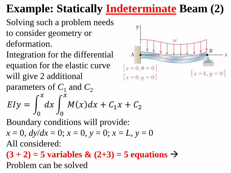
Solving such a problem needs
to consider geometry or
deformation.
Integration for the differential
equation for the elastic curve
will give 2 additional
parameters of C1 and C2
Example: Statically Indeterminate Beam (2)
Boundary conditions will provide:
x = 0, dy/dx = 0; x = 0, y = 0; x = L, y = 0
All considered:
(3 + 2) = 5 variables & (2+3) = 5 equations
Problem can be solved
𝐸𝐼𝑦 = න0
𝑥
𝑑𝑥න0
𝑥
𝑀 𝑥 𝑑𝑥 + 𝐶1𝑥 + 𝐶2

Example: Statically Indeterminate Beam (3)
Integrating wrt. x
FBD for AC is drawn
Equilibrium of M around C gives:
A CAy V
w
M
wx
0.5x
MA
x
xAwxMxM yA 2
2
1)(
Ay MxAwxxMdx
ydEI 2
2
2
2
1)(
1
23
2
1
6
1CxMxAwx
dx
dyEI Ay
21
234
2
1
6
1
24
1CxCxMxAwxEIy Ay
Therefore,

Remember
Consider 3 boundary conditions:
1
23
2
1
6
1CxMxAwx
dx
dyEI Ay
21
234
2
1
6
1
24
1CxCxMxAwxEIy Ay
x = 0, dy/dx = 0
x = 0, y = 0
x = L, y = 0
01 C
02 C
2
24
1
2
1
6
1wLMLA Ay
∑Fy = 0 wLBAy
∑MA = 0 2
2
1wLBLM A
wLAy8
5
2
8
1wLM A
wLB8
3
Example: Statically Indeterminate Beam (4)

Problem on right is statically
indeterminate to the 2nd degree:
Equilibrium gives 3 equations
∑Fx=0 Ax = 0
∑Fy=0 Ay + B - wL = 0
∑MA=0 MA+MB+BL=0.5wL2
4 remaining reactions
2 equations
Integration for elastic curve
gives 2 variables of C1 and C2
Consider boundary conditions
4 more equations
(4+2) = 6 variables
(2+4) = 6 equations
Statically Indeterminate Beam to 2nd Degree

Method of Superposition for Total DeflectionFor beams subject to more than one loads, local slope
(dy/dx or ) and local deflection y could be calculated
separately for each simple load (often by referring to tables
in engineering handbooks), and they could then be
combined following superposition principle at the same
position as long as:
• The stresses involved (even after combination) are well
within the proportional limit of the material
• None of the loadings will produce excessive
deformation that will impact the determination of any
other loadings
• Section considered for analysis is not too close to
loading points

Example: Superposition for Deflection
w
L
D E
L
D E
Px
xLLxxEI
wy wG
334 224
)( EIL
xLPxy PG
3
)()(
22
w
L
D E
Px
G
PGwGG yyy )()( At the same position G

EMA 3702 Mechanics & Materials Science Zhe Cheng (2018) 8 Deflection of Beams
Homework
Read textbook section 9.1, 9.2, and 9.4 and give a statement
confirm reading

EMA 3702 Mechanics & Materials Science Zhe Cheng (2018) 8 Deflection of Beams
Homework 9.1
For a simply supported prismatic beam DE with local moment at D,
please step-by-step determine (a) the equation of the elastic curve,
(b) the maximum deflection, (c) the slope at the two ends.
L
D EM

EMA 3702 Mechanics & Materials Science Zhe Cheng (2018) 8 Deflection of Beams
Homework 9.2
For a simply supported prismatic beam DE with concentrated load at G,
please step-by-step determine (a) the elastic curve y(x) for 0 < x < a and
(b) the deflection at point G.
L=a+b
D E
Pa b
G

EMA 3702 Mechanics & Materials Science Zhe Cheng (2018) 8 Deflection of Beams
Homework 9.3
For a prismatic cantilever beam DE with D side on roller and subject
to moment M0 and E side fixed, please step-by-step determine (a) the
elastic curve y(x) and (b) reactions at D and E
L
DE
M0

EMA 3702 Mechanics & Materials Science Zhe Cheng (2018) 8 Deflection of Beams
Homework 9.4
For cantilever beam with both distributed and concentrated load as
illustrated, please determine the slope and deflection at D end. (Hint: to
treat concentrated load at G alone, section GE will behave like a
cantilever beam under vertical load at the end (case 1 of textbook
Appendix D), while section DG remains straight.)
L
DE
w=P/L
P
G
0.5L