eletions are struck through, and additions€¦ · Svensson flame-retardant energy saving material,...
78
Please respond to: SB-8 Mayo Building Tallahassee, Florida 32399 September 25, 2012 ADDENDUM 4 TO: Vendors FROM: Christie Hutchinson, Purchasing Director RE: Invitation to Bid Number ITB/PI-12/13-02 THE CONSTRUCTION OF GREENHOUSES AND HEAD HOUSES AT THE CITRUS REPOSITORY This Addendum is to provide potential bidders with changes, additions and answers to questions received in reference to Invitation to Bid Number ITB/PI-12/13-02. Deletions are struck through, and additions are highlighted. BID OPENING The bid opening will be on September 28, 2012 October 5, 2012 at 2:00 p.m. Location of bid opening is Department of Agriculture and Consumer Services, Bureau of General Services, 407 S. Calhoun Street, Mayo Building, Room SB-8, Tallahassee, Florida 32399-0800. Chiller Specification for the Greenhouse Additional chiller specification requirements to the previously outlined specifications shall be as follows: ■ The complete package shall “Provide a performance based contract to provide a fully functional pre- engineered system, to include the electrical services needed to power the chiller system. The proposed building electrical services, plumbing services, and make up water services may have to be upgraded (as part of this bid package) to accept the chiller electrical loads.” ■ The minimum efficiency for these chillers shall be: Min. 10 EER & Min. 15 IPLV ■ Provide variable volume flow for energy savings to include Primary Variable Volume Pump Flow. ■ The control system for the chiller shall be Direct digital Controls (Bacnet) providing lead/lag of equipment, proof of flow pump control, chilled water temperature control, load control of chillers. Questions/Answers 1. Will the greenhouse manufacturer be responsible for providing stamped engineered drawings for the foundation, or will the owner’s architectural firm be responsible for this? The greenhouse manufacturer via the general contractor will be responsible for the engineered signed and sealed drawings. 2. What are the specifications for the clear fabric used in the Germplasm Cool House Energy Curtain System? Energy Curtains (No Substitute): Wadsworth Slope-Flat-Slope energy/shade push-pull system is to be included in each of the four growing areas. Each system will operate independently, controlled by the
Transcript of eletions are struck through, and additions€¦ · Svensson flame-retardant energy saving material,...
Please respond to: SB-8 Mayo Building Tallahassee, Florida 32399 September 25, 2012 ADDENDUM 4
TO: Vendors FROM: Christie Hutchinson, Purchasing Director RE: Invitation to Bid Number ITB/PI-12/13-02
THE CONSTRUCTION OF GREENHOUSES AND HEAD HOUSES AT THE CITRUS REPOSITORY
This Addendum is to provide potential bidders with changes, additions and answers to questions received in reference to Invitation to Bid Number ITB/PI-12/13-02. Deletions are struck through, and additions are highlighted. BID OPENING The bid opening will be on September 28, 2012 October 5, 2012 at 2:00 p.m. Location of bid opening is Department of Agriculture and Consumer Services, Bureau of General Services, 407 S. Calhoun Street, Mayo Building, Room SB-8, Tallahassee, Florida 32399-0800. Chiller Specification for the Greenhouse Additional chiller specification requirements to the previously outlined specifications shall be as follows: ■ The complete package shall “Provide a performance based contract to provide a fully functional pre-
engineered system, to include the electrical services needed to power the chiller system. The proposed building electrical services, plumbing services, and make up water services may have to be upgraded (as part of this bid package) to accept the chiller electrical loads.”
■ The minimum efficiency for these chillers shall be: Min. 10 EER & Min. 15 IPLV ■ Provide variable volume flow for energy savings to include Primary Variable Volume Pump Flow. ■ The control system for the chiller shall be Direct digital Controls (Bacnet) providing lead/lag of
equipment, proof of flow pump control, chilled water temperature control, load control of chillers. Questions/Answers 1. Will the greenhouse manufacturer be responsible for providing stamped engineered drawings for
the foundation, or will the owner’s architectural firm be responsible for this? The greenhouse manufacturer via the general contractor will be responsible for the engineered signed
and sealed drawings. 2. What are the specifications for the clear fabric used in the Germplasm Cool House Energy
Curtain System? Energy Curtains (No Substitute): Wadsworth Slope-Flat-Slope energy/shade push-pull system is to be
included in each of the four growing areas. Each system will operate independently, controlled by the
ADDENDUM 4 September 25, 2012 Page 2 Enviro-Step controller in each greenhouse growing area. Shade factor of fabric is to be XLS 13
Firebreak fabric as manufactured by Ludvig Svenson Company. In the east, air-conditioned greenhouse only, the system will pull a clear fabric when in open position and the XLS 13 Firebreak shade cloth when in the closed position. Also, add the Clear Energy Fabric in CGIP’s Cool Greenhouse should be Svensson flame-retardant energy saving material, XLS10 Revolux made of 100% polyester.
3. For the Budwood Greenhouse range, is the Svensson OLS 70 supposed to cover the insect
screening as well? Yes, the shadecloth will also need to be the Svensson product. 4. What sensors are required with the Microgrow Procom Growmaster series automatic control? The main functions are temperature control and the ability to activate fans and sump pumps. All of the
information necessary is included with the Procom system. The contractor should contact Microgrow for other information.
5. What sensors are required in the Germplasm greenhouse for the environmental controls (soil
moisture, light, temp humidity, etc.)? The main functions are temperature control and the ability to activate fans and sump pumps. 6. Will the owner/architect accept a 6/12 pitch instead of a 3/12 pitch? Bows will need to be 30’. The pitch can be changed as long as the gutters can handle the roof runoff
without flooding the house. 7. Are the heaters in the greenhouse LP gas or Natural gas. The heaters are LP. 8. Is an IGROW 1400 controller by Link4 an acceptable substitute for the Four Wadsworth
Envirostep control systems and the Four Sterling 18 station irrigation controllers? No. Use the Wadsworth STEP50A. 9. Will fans with galvanized steel housing and aluminum shutters be acceptable on the exhaust
fans? No. 10. I noticed the control specifications (15900) for Budwood and Germplasm indicate the control
manufacturer as “Computrol” only. Can other be acceptable? Yes, see attached revised section 15900. 11. In regard to the order and organization of the drawings, did you intend to provide two sets of
separate drawings, one with the Budwood, and the other with the Germplasm? Or, were your intentions to provide one complete set of drawings? I did refer to the list of drawings on each cover sheet, but I also noticed some discrepancies with the drawings listed and the drawing pdfs that were provided. I would only like to know how it is that you intended on arranging and organizing the drawings.
One project with two separate buildings and two greenhouses with one alternate greenhouse.
ADDENDUM 4 September 25, 2012 Page 3 12. On the Germplasm building drawings, the index shows civil drawings that were not included with
the drawings. Civil drawings were available after the architectural plans and are available at the printer (ARC,
Gainesville, 3239 SW 47 Ave Suite 300, Gainesville, Florida 32608; Telephone (352) 371-5772, (352) 371-1188; [email protected]).
13. The index also does not show a sheet M400 which was provided with the set. Civil drawings were available after the architectural plans and are available at the printer (ARC,
Gainesville, 3239 SW 47 Ave Suite 300, Gainesville, Florida 32608; Telephone (352) 371-5772, (352) 371-1188; [email protected]). This sheet should be included as part of the set.
14. The Budwood drawings index does not show sheet G001 which was included with the set. Civil drawings were available after the architectural plans and are available at the printer (ARC,
Gainesville, 3239 SW 47 Ave Suite 300, Gainesville, Florida 32608; Telephone (352) 371-5772, (352) 371-1188; [email protected]). This sheet should be included as part of the set.
15. Missing civil drawings and update the drawing indexes. See #’s 12, 13 and 14. 16. Please confirm that all appliances and growth chambers will be provided and installed by owner. The appliances and growth chambers will be provided and installed by owner. 17. Conference Room 107 shows a projector and screen. Are these owner furnished items? Yes, owner will furnish; general contractor to install. 18. Please provide a specification and schedule for all of the signs needed for this project. Please provide a $2,500 sign allowance. 19. It seems that the HVAC control contractor on the plans is out of business or something’s up. Is
ok to have other companies price this work? The name of the company in the plans should be deleted. The general contractors and his sub-
contractors will be doing the work. 20. Per Sheet 6 of 13 (Paving, Grading & Drainage Plan) – note #1 at bottom of page refers to soils
report. There is no soils report in the spec book please provide.
Attached please see soils report. 21. Per sheet 5 of 13 (Site Plan ) & thru-out civils/ landscaping showing this - there is note for weed
mat that references the architectural Plans and specifications- when you go to the A drawings it shows concrete instead of weed mat. Are we to bid per civil drawings or architectural. If civil, please provide detail for the weed mat / stone that is on it etc. If Architectural, please provide overall site plan showing concrete work for the site not just at buildings. Layout / design between civils & architectural do not match in all area’s.
The concrete areas shown on the architectural drawings shall be provided. The balance of the areas not
shown on the architectural plans as concrete shall receive 6’ min. of weed mat as per the civil documents.
ADDENDUM 4 September 25, 2012 Page 4 22. An automatic irrigation system is specified to be installed, but I do not see an irrigation plan or
specifications for the system. Is this to be designed and installed by the contractor, or am I missing sheets in the project documents?
It will be installed by owner. 23. There are no sod areas indicated on the Landscape Plan. It seems a good portion of the site will
be disturbed, so could you clarify what (if any) areas are to be sodded and what type of sod is to be used?
The disturbed areas of the project shall be priced with bahia sod throughout. Please provide a line item
price for this work. An alternate price will be provided to provided seed and straw protection in the general areas and bahia sod at the perimeter of greenhouses and buildings.
24. Addendum 1 in “clarification on Budwood and Germplasm buildings” #5, says the storefront
doors to be “as” per note 5 on sheet A601.1. That note says they are Kawneer 190 narrow stile doors. Is this a closed spec, or will Vistawall or YKK be allowed? They both make an identical door, with Florida Product Approvals, to the Kawneer door.
This is not a closed spec. Other door manufacturers are allowed. 25. Can you please address issues of drainage from the Germplasm Greenhouses (to include drains,
traps and treatment) which were not included in Addendum 1? At the end of the center trench drain system that exits out of the greenhouse, a full size pvc pea trap
(similar to a sink) should be provided that would prevent insects from entering (walking/crawling or flying) from the exterior to the interior of the greenhouse.
26. Addenda No. 1, Item # 8 under clarification for the greenhouses - Previous descriptions for doors
were 3’0” x 6’8” galvanized. The doors should be aluminum, not galvanized. 27. Specification 15080.3.10 - Mechanical Insulation calls for the flexible duct wrap to be 2” thick x
1.5 lb/ft³density (installed R-6.4) and the rigid board duct insulation to be 2.0” thick x 1.5 lb/ft³ (installed R-8.3). In the insulation industry, the following would provide from 15-25% first cost savings while giving a greater installed R-Factor as follows. We would propose to install flexible duct wrap to be 2.25” thick x .75 lb/ft³density (installed R-6.5) and the rigid board duct insulation to be 2.0” thick x 3.0 lb/ft³ (installed R-8.7). In the case of the flexible duct wrap, the thickness is giving the greater R-Factor and the industry standard of using the 2.25”x.75# wrap contributes to the decreased first-cost. In the case of the duct board, the higher density is giving the greater R-Factor and since the 2.0”x1.5# board comes without a jacket, the 2.0”x3.0# board with jacket contributes to the decreased first-cost.
We would respectfully request to use the recommended insulation as outlined. 28. We would respectfully request direction for the Building Automation System. TLC Response dated 9/18/12 as follows: Trane, JCI, FIS, Alerton, Automated Logic, Siemens are
acceptable.
ADDENDUM 4 September 25, 2012 Page 5 29. Can you please clarify the requirement for the “motorized dampers” or “exhaust fan dampers” in
the Budwood indexing greenhouse and the alternate? “Motorized and/or Exhaust Fan Dampers” shall be Tamco Series 1000SW, 56" x 56", with Belimo 120V
spring return actuators. 30. Germplasm and Budwood– Roof Mounted Exhaust Fans.
a. None shown on roof plan. Mechanical plans show fans on the roof. b. No structural supports shown. Trusses to be reinforced to accept the weight of the roof exhaust fans and curb. c. Will a Service platform and railing be required? No service platform or railing will be required. d. How will access to the roof be obtained? Access to the roof will be provided via ladders. e. EF-2 – Noted on plan sheet M201 to be located on the roof however it appears that the fan
is actually drawn as an in-line. Which one is correct? The fan is an in line fan.
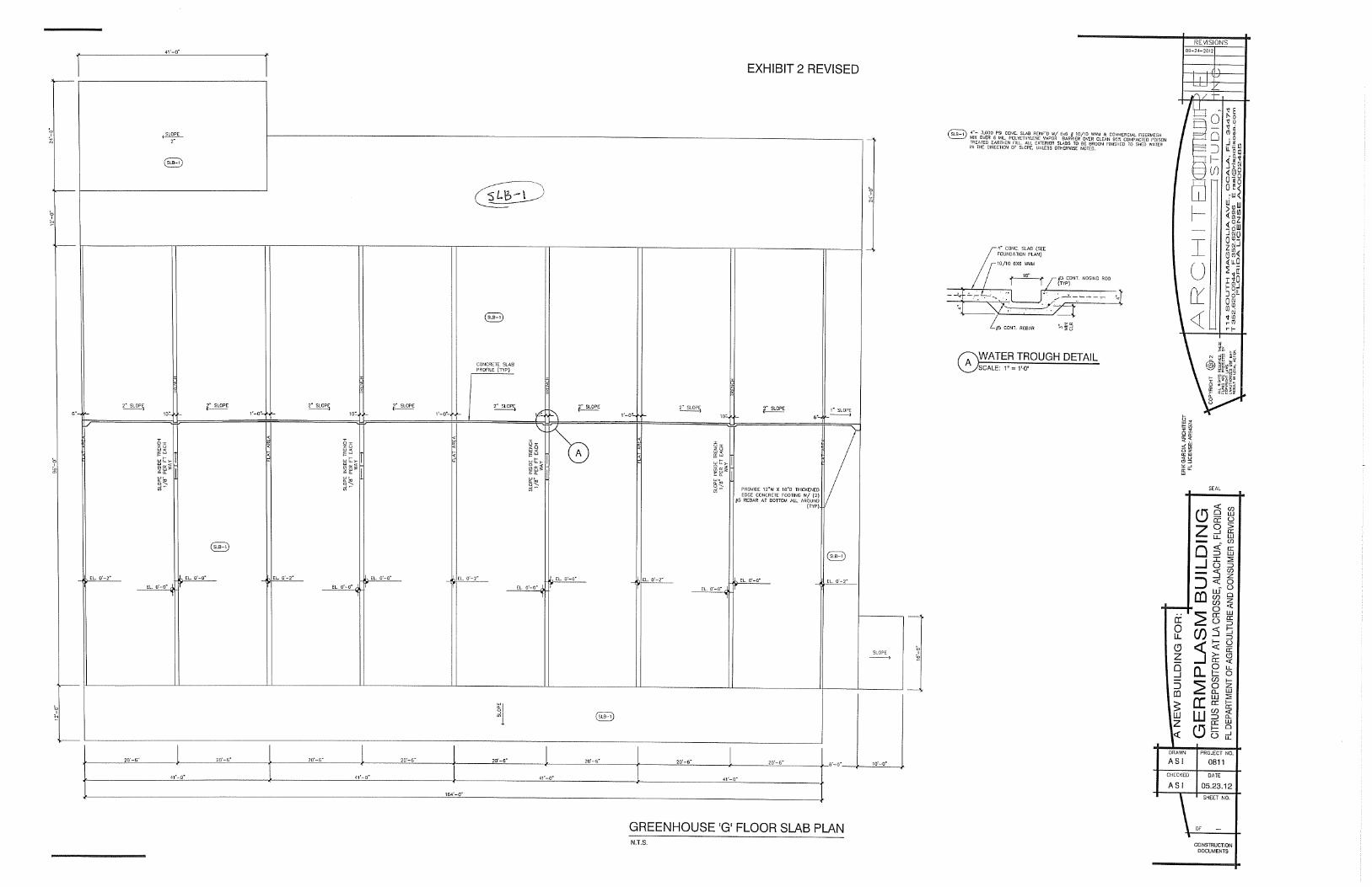
31. Is a 12’ wide x 55.4’ long 4” thick concrete slab required, just south of the germplasm building
and the greenhouse and the crushed stone service drive? Yes, the slab is shown on the civil plans on sheet 5 of 11 and shall be 4” – 3000 psi concrete and reinf’d
with 6 x 6 wwm over 6 mil visqueen over 98% compacted earthen fill dirt with a broom finish, slope away from building and greenhouse.
32. The wall section for both the Germplasm and the Budwood buildings, where suspended
acoustical ceilings occur, illustrate and call out R-30 kraft faced fiberglass insulation with netting connected to the bottom of the wood trusses.
In lieu of what is illustrated and specified, provide un-faced R-30 fiberglass batt insulation over Tyvek
house wrap secured to bottom of trusses. 33. What size ducts are to be used for the following areas?
a. Germplasm - Rectangular upstream of EF-5: 14 x 12 b. Germplasm - Downstream of 24/14 from EF-2: 16 x 14 & 12 x 12 c. Germplasm - Downstream of 12/12 from SF-1
Past 12 x 12 trans to 10" diameter to diffuser. 34. Germplasm AC-4: Rectangular supply duct serving rooms 120, 121 is not sized and there is no
means of controlling the air flow (No VAV Box). 6 x 6 supply duct no control required (min conditioned air for pressure control). Provide balance damper
in 6 x 6 supply for balancing (balance at max airflow).
ADDENDUM 4 September 25, 2012 Page 6 35. Budwood: What is the preferred material to be used for the exhaust duct and stack(s) for EF-5
and EF-6? Stainless, PVC, PVC coated etc.: 304 Stainless steel conforming to ASTM standards A653 and A924. 36. Germplasm - Grill / Diffuser Schedule.
a. No Mark "D". (Room 130): Provide type C diffuser for supplies to rooms with no ceiling. Provide D register for return with no ceiling. b. Mar “C” is drawn on sheet M201 as being a “lay-in” type but the grill schedule indicates
that it is a sidewall grill. Which type is correct? Provide type C or D grills and registers for hard ceilings or no ceilings. Alternately, type A and B
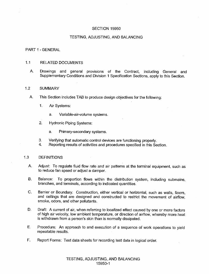
can be provided in hard ceiling applications with correct framing. 37. Spec. Section 15950 paragraph 1.2a indicates that Testing and Balancing will be “Directly
Contracted with the County Through Moss Independent of the Mechanical Contractor.” Is this correct?
No. See attached. Associated reference is a typo and is removed. 38. Spec. Section 15900 2.2a indicates that the new controls shall be “compatible with the existing
facilities system.” Is there an existing facility and system on this site? If not, is Computrol as a “sole source” valid as the only approved manufacturer? If not please provide a list of approved manufacturers for this project.
Tran, JCI, MCI, FIS, Alerton, Automated Logic and Siemens are also acceptable. NOTE: Attachments are as follows:
■ Section 15900 ■ Section 15950 ■ Revised Exhibit 2 ■ Revised “Review of M201, Mechanical Plan for Air-Conditioning Ductwork in Germplasm
Building” ■ Geotechnical Site Exploration Repot
To the extent this Addendum gives rise to a protest, failure to file a protest within the time prescribed in Section 120.57(3), Florida Statutes, shall constitute a waiver of proceedings under Chapter 120, Florida Statutes. All other terms, conditions and specifications of this Invitation to Bid will remain the same. If you have any questions regarding this addendum, please feel free to contact this office at (850) 617-7181.
HVAC INSTRUMENTATION AND CONTROLS15900-1
SECTION 15900
HVAC INSTRUMENTATION AND CONTROLS
PART 1 - GENERAL
1.1 SUMMARY
A. This Section includes control equipment for HVAC systems and components, includingcontrol components for terminal heating and cooling units not supplied with factory-wired controls.
B. Refer to "Sequence of Operation" on the drawings for requirements that relate to thisSection.
1.2 SUBMITTALS
A. Product Data: For each control device indicated.
B. Shop Drawings:
1. Schematic flow diagrams.2. Power, signal, and control wiring diagrams.3. Details of control panel faces.4. Damper schedule.5. Valve schedule.6. DDC System Hardware: Wiring diagrams, schematic floor plans, and schematic
control diagrams.7. Control System Software: Schematic diagrams, written descriptions, and points
list.
C. Software and firmware operational documentation.
D. Field quality-control test reports.
E. Operation and maintenance data.
1.3 QUALITY ASSURANCE
A. Electrical Components, Devices, and Accessories: Listed and labeled as defined inNFPA 70, Article 100, by a testing agency acceptable to authorities having jurisdiction,and marked for intended use.
HVAC INSTRUMENTATION AND CONTROLS15900-2
PART 2 - PRODUCTS
2.1 MANUFACTURERS
A. In other Part 2 articles where titles below introduce lists, the following requirementsapply to product selection:
1. Available Manufacturers: Subject to compliance with requirements,manufacturers offering products that may be incorporated into the Work include,but are not limited to, manufacturers specified.
2. Manufacturers: Subject to compliance with requirements, provide products byone of the manufacturers specified.
2.2 CONTROL SYSTEM
A. Manufacturers:
1. Computrol (located in Orlando, FL)2. Trane3. MC24. Johnson Controls5. Facility Integration Solutions6. Andover7. Alerton8. Automated Logic9. Siemens
New controls will be provided for all equipment. All controls shall have a BACNET in-terface. New controllers shall be tied into a new Energy Management/Building Automa-tion System that is compatible with the existing facility’s system. Controls will incorpo-rate night setback and heating/cooling changeover and shall be fully addressable withall mechanical equipment.
B. Control system shall consist of sensors, indicators, actuators, final control elements,interface equipment, other apparatus, accessories, wiring between all components andsoftware connected to distributed controllers operating in multi-user, multitaskingenvironment on token-passing network and programmed to control mechanicalsystems. The building will have a stand-alone control system, it will not be tied intoother Owner facilities. The control system shall be compatible with the Owner’s existingportable interface devices / diagnostic terminal units. New system shall be providedwith operator works station, laptop computer, and control units as specified.
C. Contractor shall be responsible for miscellaneous 120 volt power wiring as requiredfrom point of origin as provided by Electrical Contractor to all control components asrequired for a complete operating system. Provide all transformers, relays and controlunits as required. Install 120 volt power wiring form electrical panels to control itemsper division 16 specifications.
HVAC INSTRUMENTATION AND CONTROLS15900-3
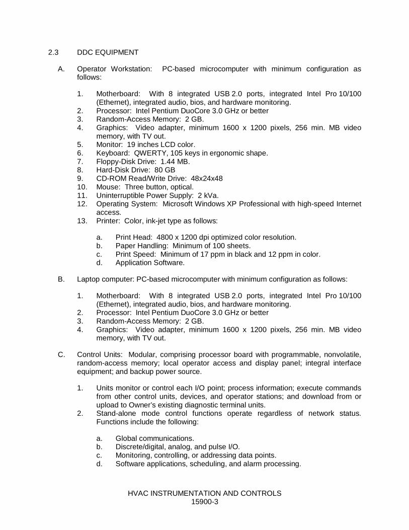
2.3 DDC EQUIPMENT
A. Operator Workstation: PC-based microcomputer with minimum configuration asfollows:
1. Motherboard: With 8 integrated USB 2.0 ports, integrated Intel Pro 10/100(Ethernet), integrated audio, bios, and hardware monitoring.
2. Processor: Intel Pentium DuoCore 3.0 GHz or better3. Random-Access Memory: 2 GB.4. Graphics: Video adapter, minimum 1600 x 1200 pixels, 256 min. MB video
memory, with TV out.5. Monitor: 19 inches LCD color.6. Keyboard: QWERTY, 105 keys in ergonomic shape.7. Floppy-Disk Drive: 1.44 MB.8. Hard-Disk Drive: 80 GB9. CD-ROM Read/Write Drive: 48x24x4810. Mouse: Three button, optical.11. Uninterruptible Power Supply: 2 kVa.12. Operating System: Microsoft Windows XP Professional with high-speed Internet
access.13. Printer: Color, ink-jet type as follows:
a. Print Head: 4800 x 1200 dpi optimized color resolution.b. Paper Handling: Minimum of 100 sheets.c. Print Speed: Minimum of 17 ppm in black and 12 ppm in color.d. Application Software.
B. Laptop computer: PC-based microcomputer with minimum configuration as follows:
1. Motherboard: With 8 integrated USB 2.0 ports, integrated Intel Pro 10/100(Ethernet), integrated audio, bios, and hardware monitoring.
2. Processor: Intel Pentium DuoCore 3.0 GHz or better3. Random-Access Memory: 2 GB.4. Graphics: Video adapter, minimum 1600 x 1200 pixels, 256 min. MB video
memory, with TV out.
C. Control Units: Modular, comprising processor board with programmable, nonvolatile,random-access memory; local operator access and display panel; integral interfaceequipment; and backup power source.
1. Units monitor or control each I/O point; process information; execute commandsfrom other control units, devices, and operator stations; and download from orupload to Owner’s existing diagnostic terminal units.
2. Stand-alone mode control functions operate regardless of network status.Functions include the following:
a. Global communications.b. Discrete/digital, analog, and pulse I/O.c. Monitoring, controlling, or addressing data points.d. Software applications, scheduling, and alarm processing.

HVAC INSTRUMENTATION AND CONTROLS15900-4
e. Testing and developing control algorithms without disrupting field hardwareand controlled environment.
D. Local Control Units: Modular, comprising processor board with electronicallyprogrammable, nonvolatile, read-only memory; and backup power source.
1. Units monitor or control each I/O point, process information, and download fromor upload to Owner’s existing diagnostic terminal unit.
2. Stand-alone mode control functions operate regardless of network status.Functions include the following:
a. Global communications.b. Discrete/digital, analog, and pulse I/O.c. Monitoring, controlling, or addressing data points.
3. Local operator interface provides for download from or upload to Owner’sexisting diagnostic terminal units.
E. I/O Interface: Hardwired inputs and outputs may tie into system through controllers.Protect points so that shorting will cause no damage to controllers.
1. Binary Inputs: Allow monitoring of on-off signals without external power.2. Pulse Accumulation Inputs: Accept up to 10 pulses per second.3. Analog Inputs: Allow monitoring of low-voltage (0- to 10-V dc), current (4 to 20
mA), or resistance signals.4. Binary Outputs: Provide on-off or pulsed low-voltage signal, selectable for
normally open or normally closed operation with three-position (on-off-auto)override switches and status lights.
5. Analog Outputs: Provide modulating signal, either low voltage (0- to 10-V dc) orcurrent (4 to 20 mA) with status lights, two-position (auto-manual) switch, andmanually adjustable potentiometer.
6. Tri-State Outputs: Provide two coordinated binary outputs for control of three-point, floating-type electronic actuators.
7. Universal I/Os: Provide software selectable binary or analog outputs.
F. Power Supplies: Transformers with Class 2 current-limiting type or overcurrentprotection; limit connected loads to 80 percent of rated capacity. DC power supplyshall match output current and voltage requirements and be full-wave rectifier type withthe following:
1. Output ripple of 5.0 mV maximum peak to peak.2. Combined 1 percent line and load regulation with 100-mic.sec. response time for
50 percent load changes.3. Built-in overvoltage and overcurrent protection and be able to withstand 150
percent overload for at least 3 seconds without failure.
G. Power Line Filtering: Internal or external transient voltage and surge suppression forworkstations or controllers with the following:
1. Minimum dielectric strength of 1000 V.
HVAC INSTRUMENTATION AND CONTROLS15900-5
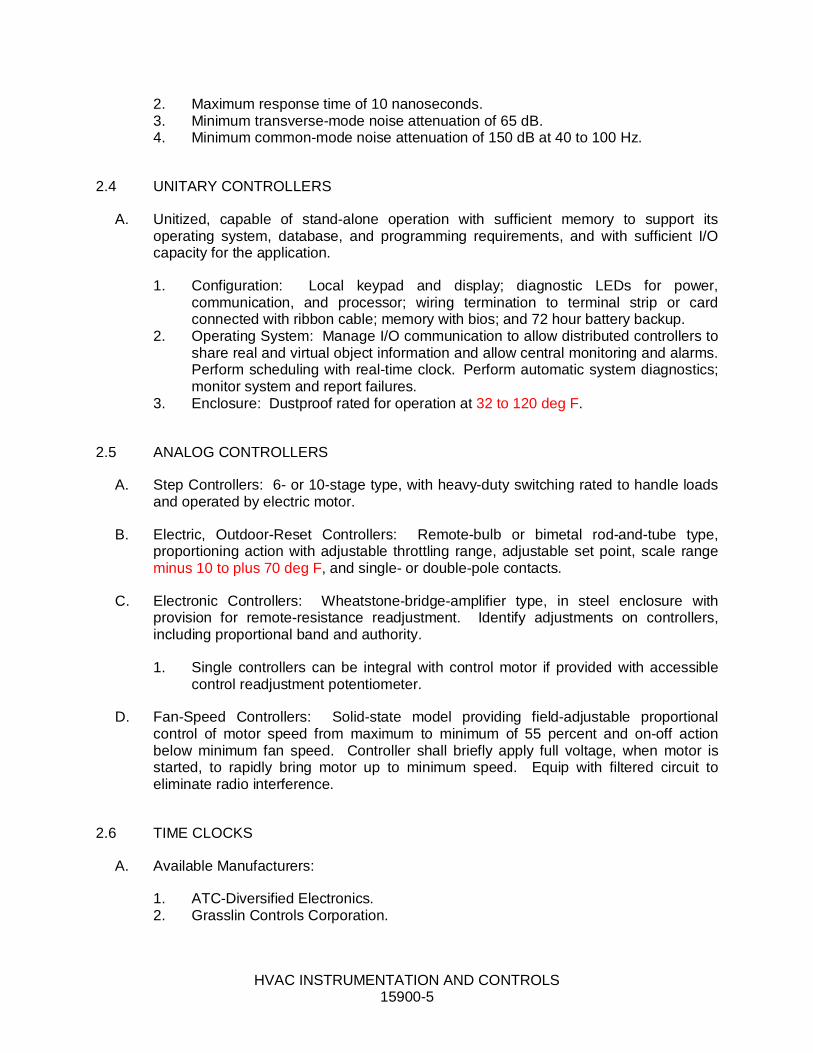
2. Maximum response time of 10 nanoseconds.3. Minimum transverse-mode noise attenuation of 65 dB.4. Minimum common-mode noise attenuation of 150 dB at 40 to 100 Hz.
2.4 UNITARY CONTROLLERS
A. Unitized, capable of stand-alone operation with sufficient memory to support itsoperating system, database, and programming requirements, and with sufficient I/Ocapacity for the application.
1. Configuration: Local keypad and display; diagnostic LEDs for power,communication, and processor; wiring termination to terminal strip or cardconnected with ribbon cable; memory with bios; and 72 hour battery backup.
2. Operating System: Manage I/O communication to allow distributed controllers toshare real and virtual object information and allow central monitoring and alarms.Perform scheduling with real-time clock. Perform automatic system diagnostics;monitor system and report failures.
3. Enclosure: Dustproof rated for operation at 32 to 120 deg F.
2.5 ANALOG CONTROLLERS
A. Step Controllers: 6- or 10-stage type, with heavy-duty switching rated to handle loadsand operated by electric motor.
B. Electric, Outdoor-Reset Controllers: Remote-bulb or bimetal rod-and-tube type,proportioning action with adjustable throttling range, adjustable set point, scale rangeminus 10 to plus 70 deg F, and single- or double-pole contacts.
C. Electronic Controllers: Wheatstone-bridge-amplifier type, in steel enclosure withprovision for remote-resistance readjustment. Identify adjustments on controllers,including proportional band and authority.
1. Single controllers can be integral with control motor if provided with accessiblecontrol readjustment potentiometer.
D. Fan-Speed Controllers: Solid-state model providing field-adjustable proportionalcontrol of motor speed from maximum to minimum of 55 percent and on-off actionbelow minimum fan speed. Controller shall briefly apply full voltage, when motor isstarted, to rapidly bring motor up to minimum speed. Equip with filtered circuit toeliminate radio interference.
2.6 TIME CLOCKS
A. Available Manufacturers:
1. ATC-Diversified Electronics.2. Grasslin Controls Corporation.
HVAC INSTRUMENTATION AND CONTROLS15900-6
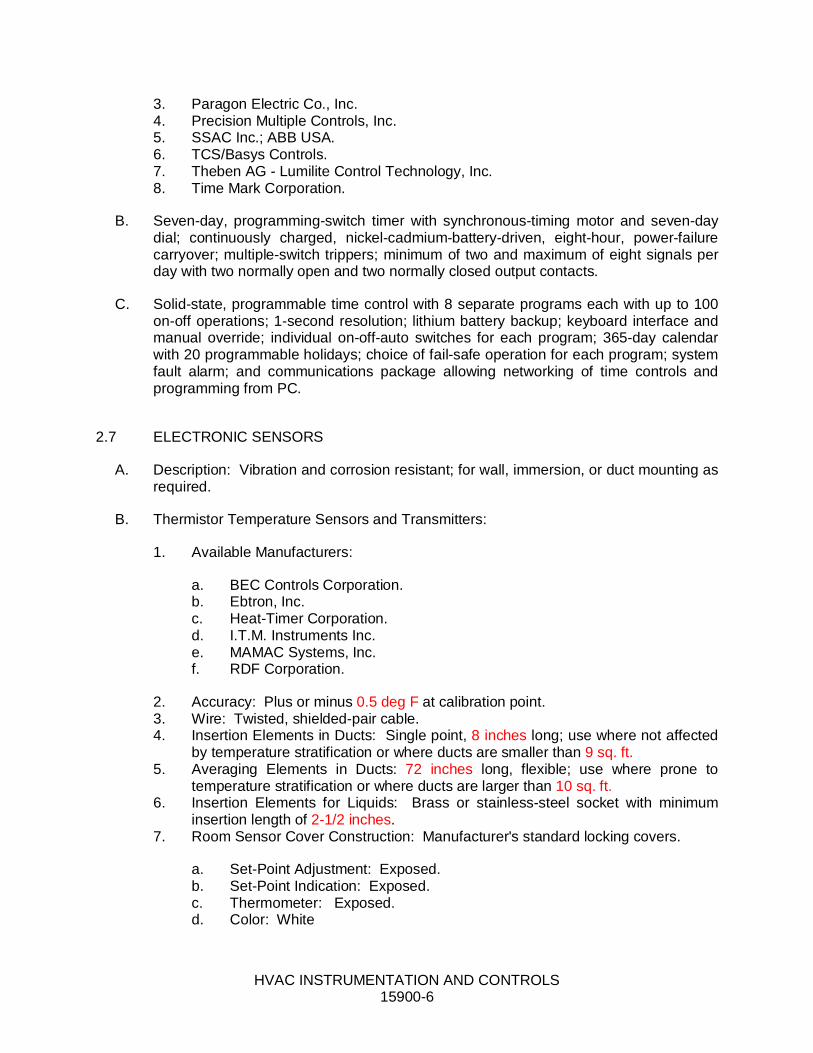
3. Paragon Electric Co., Inc.4. Precision Multiple Controls, Inc.5. SSAC Inc.; ABB USA.6. TCS/Basys Controls.7. Theben AG - Lumilite Control Technology, Inc.8. Time Mark Corporation.
B. Seven-day, programming-switch timer with synchronous-timing motor and seven-daydial; continuously charged, nickel-cadmium-battery-driven, eight-hour, power-failurecarryover; multiple-switch trippers; minimum of two and maximum of eight signals perday with two normally open and two normally closed output contacts.
C. Solid-state, programmable time control with 8 separate programs each with up to 100on-off operations; 1-second resolution; lithium battery backup; keyboard interface andmanual override; individual on-off-auto switches for each program; 365-day calendarwith 20 programmable holidays; choice of fail-safe operation for each program; systemfault alarm; and communications package allowing networking of time controls andprogramming from PC.
2.7 ELECTRONIC SENSORS
A. Description: Vibration and corrosion resistant; for wall, immersion, or duct mounting asrequired.
B. Thermistor Temperature Sensors and Transmitters:
1. Available Manufacturers:
a. BEC Controls Corporation.b. Ebtron, Inc.c. Heat-Timer Corporation.d. I.T.M. Instruments Inc.e. MAMAC Systems, Inc.f. RDF Corporation.
2. Accuracy: Plus or minus 0.5 deg F at calibration point.3. Wire: Twisted, shielded-pair cable.4. Insertion Elements in Ducts: Single point, 8 inches long; use where not affected
by temperature stratification or where ducts are smaller than 9 sq. ft.5. Averaging Elements in Ducts: 72 inches long, flexible; use where prone to
temperature stratification or where ducts are larger than 10 sq. ft.6. Insertion Elements for Liquids: Brass or stainless-steel socket with minimum
insertion length of 2-1/2 inches.7. Room Sensor Cover Construction: Manufacturer's standard locking covers.
a. Set-Point Adjustment: Exposed.b. Set-Point Indication: Exposed.c. Thermometer: Exposed.d. Color: White
HVAC INSTRUMENTATION AND CONTROLS15900-7
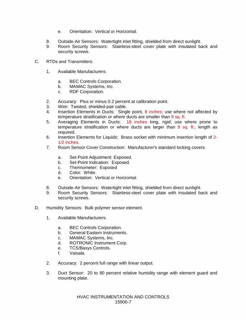
e. Orientation: Vertical or Horizontal.
8. Outside-Air Sensors: Watertight inlet fitting, shielded from direct sunlight.9. Room Security Sensors: Stainless-steel cover plate with insulated back and
security screws.
C. RTDs and Transmitters:
1. Available Manufacturers:
a. BEC Controls Corporation.b. MAMAC Systems, Inc.c. RDF Corporation.
2. Accuracy: Plus or minus 0.2 percent at calibration point.3. Wire: Twisted, shielded-pair cable.4. Insertion Elements in Ducts: Single point, 8 inches; use where not affected by
temperature stratification or where ducts are smaller than 9 sq. ft.5. Averaging Elements in Ducts: 18 inches long, rigid; use where prone to
temperature stratification or where ducts are larger than 9 sq. ft.; length asrequired.
6. Insertion Elements for Liquids: Brass socket with minimum insertion length of 2-1/2 inches.
7. Room Sensor Cover Construction: Manufacturer's standard locking covers.
a. Set-Point Adjustment: Exposed.b. Set-Point Indication: Exposed.c. Thermometer: Exposedd. Color: White.e. Orientation: Vertical or Horizontal.
8. Outside-Air Sensors: Watertight inlet fitting, shielded from direct sunlight.9. Room Security Sensors: Stainless-steel cover plate with insulated back and
security screws.
D. Humidity Sensors: Bulk polymer sensor element.
1. Available Manufacturers:
a. BEC Controls Corporation.b. General Eastern Instruments.c. MAMAC Systems, Inc.d. ROTRONIC Instrument Corp.e. TCS/Basys Controls.f. Vaisala.
2. Accuracy: 2 percent full range with linear output.
3. Duct Sensor: 20 to 80 percent relative humidity range with element guard andmounting plate.
HVAC INSTRUMENTATION AND CONTROLS15900-8
4. Duct and Sensors: With element guard and mounting plate, range of 0 to 100percent relative humidity.
2.8 STATUS SENSORS
A. Status Inputs for Fans: Differential-pressure switch with pilot-duty rating and withadjustable range of 0- to 5-inch wg.
2.9 THERMOSTATS
A. Available Manufacturers:
1. Erie Controls.2. Danfoss Inc.; Air-Conditioning and Refrigeration Div.3. Heat-Timer Corporation.4. Sauter Controls Corporation.5. tekmar Control Systems, Inc.6. Theben AG - Lumilite Control Technology, Inc.
B. Electric, solid-state, microcomputer-based room thermostat with remote sensor.
1. Automatic switching from heating to cooling.2. Preferential rate control to minimize overshoot and deviation from set point.3. Set up for four separate temperatures per day.4. Instant override of set point for continuous or timed period from 1 hour to 31
days.5. Short-cycle protection.6. Programming based on every day of week.7. Selection features include degree F or degree C display, 12- or 24-hour clock,
keyboard disable, remote sensor, and fan on-auto.8. Battery replacement without program loss.9. Thermostat display features include the following:
a. Time of day.b. Actual room temperature.c. Programmed temperature.d. Programmed time.e. Duration of timed override.f. Day of week.g. System mode indications include "heating," "off," "fan auto," and "fan on."
C. Low-Voltage, On-Off Thermostats: NEMA DC 3, 24-V, bimetal-operated, mercury-switch type, with adjustable or fixed anticipation heater, concealed set-pointadjustment, 55 to 85 deg F set-point range, and 2 deg F maximum differential.
HVAC INSTRUMENTATION AND CONTROLS15900-9
D. Line-Voltage, On-Off Thermostats: Bimetal-actuated, open contact or bellows-actuated, enclosed, snap-switch or equivalent solid-state type, with heat anticipator;listed for electrical rating; with concealed set-point adjustment, 55 to 85 deg F set-pointrange, and 2 deg F maximum differential.
1. Electric Heating Thermostats: Equip with off position on dial wired to breakungrounded conductors.
2. Selector Switch: Integral, manual on-off-auto.
E. Remote-Bulb Thermostats: On-off or modulating type, liquid filled to compensate forchanges in ambient temperature; with copper capillary and bulb, unless otherwiseindicated.
1. Bulbs in water lines with separate wells of same material as bulb.2. Bulbs in air ducts with flanges and shields.3. Averaging Elements: Copper tubing with either single- or multiple-unit elements,
extended to cover full width of duct or unit; adequately supported.4. Scale settings and differential settings are clearly visible and adjustable from
front of instrument.5. On-Off Thermostat: With precision snap switches and with electrical ratings
required by application.6. Modulating Thermostats: Construct so complete potentiometer coil and wiper
assembly is removable for inspection or replacement without disturbingcalibration of instrument.
F. Room Thermostat Cover Construction: Manufacturer's standard locking covers.
1. Set-Point Adjustment: Exposed.2. Set-Point Indication: Exposed.3. Thermometer: Exposed.4. Color: White.5. Orientation: Vertical or Horizontal.
G. Room thermostat accessories include the following:
1. Insulating Bases: For thermostats located on exterior walls.2. Thermostat Guards: Locking; heavy-duty, transparent plastic; mounted on
separate base.3. Adjusting Key: As required for calibration and cover screws.4. Set-Point Adjustment: 1/2-inch- diameter, adjustment knob.
2.10 HUMIDISTATS
A. Available Manufacturers:
1. MAMAC Systems, Inc.2. ROTRONIC Instrument Corp.

HVAC INSTRUMENTATION AND CONTROLS15900-10
B. Duct-Mounting Humidistats: Electric insertion, 2-position type with adjustable, 2percent throttling range, 20 to 80 percent operating range, and single- or double-polecontacts.
2.11 ACTUATORS
A. Electric Motors: Size to operate with sufficient reserve power to provide smoothmodulating action or two-position action.
1. Comply with requirements in Division 15 Section "Motors."2. Permanent Split-Capacitor or Shaded-Pole Type: Gear trains completely oil
immersed and sealed. Equip spring-return motors with integral spiral-springmechanism in housings designed for easy removal for service or adjustment oflimit switches, auxiliary switches, or feedback potentiometer.
3. Nonspring-Return Motors for Dampers Larger than 25 Sq. Ft.: Size for runningtorque of 150 in. x lbf and breakaway torque of 300 in. x lbf.
4. Spring-Return Motors for Dampers Larger than 25 Sq. Ft.: Size for running andbreakaway torque of 150 in. x lbf.
B. Electronic Actuators: Direct-coupled type designed for minimum 60,000 full-strokecycles at rated torque.
1. Available Manufacturers:
a. Belimo Aircontrols (USA), Inc.
2. Dampers: Size for running torque calculated as follows:
a. Parallel-Blade Damper with Edge Seals: 7 inch-lb/sq. ft. of damper.b. Opposed-Blade Damper with Edge Seals: 5 inch-lb/sq. ft. of damper.c. Parallel-Blade Damper without Edge Seals: 4 inch-lb/sq. ft of damper.d. Opposed-Blade Damper without Edge Seals: 3 inch-lb/sq. ft. of damper.e. Dampers with 2- to 3-Inch wg of Pressure Drop or Face Velocities of 1000
to 2500 fpm: Increase running torque by 1.5.f. Dampers with 3- to 4-Inch wg of Pressure Drop or Face Velocities of 2500
to 3000 fpm: Increase running torque by 2.0.
3. Coupling: V-bolt and V-shaped, toothed cradle.4. Overload Protection: Electronic overload or digital rotation-sensing circuitry.5. Fail-Safe Operation: Mechanical, spring-return mechanism. Provide external,
manual gear release on nonspring-return actuators.6. Power Requirements (Two-Position Spring Return): 24 120 230-V ac.7. Power Requirements (Modulating): Maximum 10 VA at 24-V ac or 8 W at 24-V
dc.8. Proportional Signal: 2- to 10-V dc or 4 to 20 mA, and 2- to 10-V dc position
feedback signal.9. Temperature Rating: Minus 22 to plus 122 deg F.10. Run Time: 12 seconds open, 5 seconds closed.
HVAC INSTRUMENTATION AND CONTROLS15900-11
2.12 DAMPERS
A. Available Manufacturers:
1. Air Balance Inc.2. Don Park Inc.; Autodamp Div.3. TAMCO (T. A. Morrison & Co. Inc.).4. United Enertech Corp.5. Vent Products Company, Inc.
B. Dampers: AMCA-rated, opposed-blade design; 0.108-inch- minimum thick,galvanized-steel or 0.125-inch- minimum thick, extruded-aluminum frames with holesfor duct mounting; damper blades shall not be less than 0.064-inch- thick galvanizedsteel with maximum blade width of 8 inches and length of 48 inches.
1. Secure blades to 1/2-inch- diameter, zinc-plated axles using zinc-platedhardware, with oil-impregnated sintered bronze blade bearings, blade-linkagehardware of zinc-plated steel and brass, ends sealed against spring-stainless-steel blade bearings, and thrust bearings at each end of every blade.
2. Operating Temperature Range: From minus 40 to plus 200 deg F.3. Edge Seals, Standard Pressure Applications: Closed-cell neoprene.4. Edge Seals, Low-Leakage Applications: Use inflatable blade edging or
replaceable rubber blade seals and spring-loaded stainless-steel side seals,rated for leakage at less than 10 cfm per sq. ft. of damper area, at differentialpressure of 4-inch wg when damper is held by torque of 50 in. x lbf; when testedaccording to AMCA 500D.
2.13 CONTROL CABLE
A. The Division 15 controls contractor shall provide all control cable as required betweencontrol components. Electronic and fiber-optic cables for control wiring shall complywith Division 16 specifications.
PART 3 - EXECUTION
3.1 INSTALLATION
A. Verify location of thermostats, humidistats, and other exposed control sensors withDrawings and room details before installation. Install devices 48 inches above thefloor.
1. Install averaging elements in ducts and plenums in crossing or zigzag pattern.
B. Install guards on thermostats in the following locations:
1. Entrances.2. Public areas.
HVAC INSTRUMENTATION AND CONTROLS15900-12
3. Where indicated.
C. Install automatic dampers according to Division 15 Section "Duct Accessories."
D. Install damper motors on outside of duct in warm areas, not in locations exposed tooutdoor temperatures.
E. Install labels and nameplates to identify control components according to Division 15Section "Mechanical Identification."
F. Install refrigerant instrument wells, valves, and other accessories according toDivision 15 Section "Refrigerant Piping."
G. Install duct volume-control dampers according to Division 15 Sections specifying airducts.
H. Install electronic and fiber-optic cables according to Division 16 Section "Voice andData Communication Cabling."
3.2 ELECTRICAL WIRING AND CONNECTION INSTALLATION
A. Install raceways, boxes, and cabinets according to Division 16 Section "Raceways andBoxes."
B. Install building wire and cable according to Division 16 Section "Conductors andCables."
C. Install signal and communication cable according to Division 16 Section "Voice andData Communication Cabling."
1. Conceal cable, except in mechanical rooms and areas where other conduit andpiping are exposed.
2. Install exposed cable in raceway.3. Install concealed cable in raceway.4. Bundle and harness multiconductor instrument cable in place of single cables
where several cables follow a common path.5. Fasten flexible conductors, bridging cabinets and doors, along hinge side; protect
against abrasion. Tie and support conductors.6. Number-code or color-code conductors for future identification and service of
control system, except local individual room control cables.7. Install wire and cable with sufficient slack and flexible connections to allow for
vibration of piping and equipment.
D. Connect manual-reset limit controls independent of manual-control switch positions.Automatic duct heater resets may be connected in interlock circuit of power controllers.
E. Connect hand-off-auto selector switches to override automatic interlock controls whenswitch is in hand position.
HVAC INSTRUMENTATION AND CONTROLS15900-13
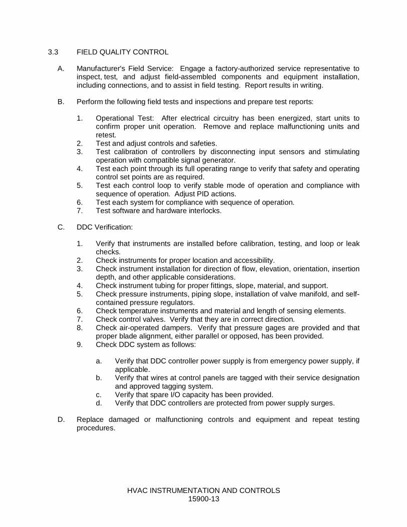
3.3 FIELD QUALITY CONTROL
A. Manufacturer's Field Service: Engage a factory-authorized service representative toinspect, test, and adjust field-assembled components and equipment installation,including connections, and to assist in field testing. Report results in writing.
B. Perform the following field tests and inspections and prepare test reports:
1. Operational Test: After electrical circuitry has been energized, start units toconfirm proper unit operation. Remove and replace malfunctioning units andretest.
2. Test and adjust controls and safeties.3. Test calibration of controllers by disconnecting input sensors and stimulating
operation with compatible signal generator.4. Test each point through its full operating range to verify that safety and operating
control set points are as required.5. Test each control loop to verify stable mode of operation and compliance with
sequence of operation. Adjust PID actions.6. Test each system for compliance with sequence of operation.7. Test software and hardware interlocks.
C. DDC Verification:
1. Verify that instruments are installed before calibration, testing, and loop or leakchecks.
2. Check instruments for proper location and accessibility.3. Check instrument installation for direction of flow, elevation, orientation, insertion
depth, and other applicable considerations.4. Check instrument tubing for proper fittings, slope, material, and support.5. Check pressure instruments, piping slope, installation of valve manifold, and self-
contained pressure regulators.6. Check temperature instruments and material and length of sensing elements.7. Check control valves. Verify that they are in correct direction.8. Check air-operated dampers. Verify that pressure gages are provided and that
proper blade alignment, either parallel or opposed, has been provided.9. Check DDC system as follows:
a. Verify that DDC controller power supply is from emergency power supply, ifapplicable.
b. Verify that wires at control panels are tagged with their service designationand approved tagging system.
c. Verify that spare I/O capacity has been provided.d. Verify that DDC controllers are protected from power supply surges.
D. Replace damaged or malfunctioning controls and equipment and repeat testingprocedures.

HVAC INSTRUMENTATION AND CONTROLS15900-14
3.4 DEMONSTRATION
A. Engage a factory-authorized service representative to train Owner's maintenancepersonnel to adjust, operate, and maintain HVAC instrumentation and controls. Referto Division 1 Section "Demonstration and Training."
END OF SECTION
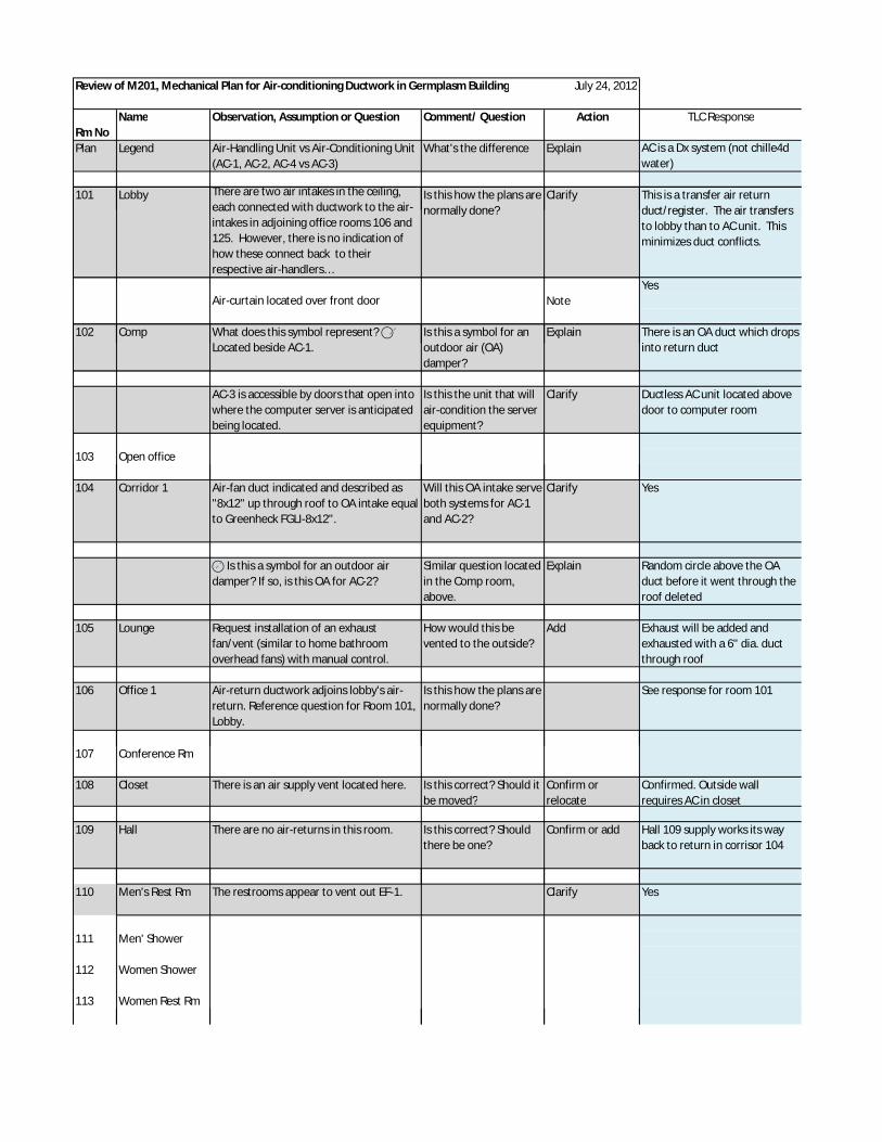
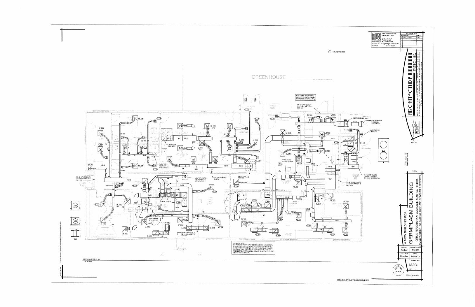
Review of M201, Mechanical Plan for Air-conditioning Ductwork in Germplasm Building July 24, 2012
Name Observation, Assumption or Question Comment/ Question Action TLC Response
Plan Legend Air-Handling Unit vs Air-Conditioning Unit(AC-1, AC-2, AC-4 vs AC-3)
What's the difference Explain AC is a Dx system (not chille4dwater)
101 Lobby There are two air intakes in the ceiling,each connected with ductwork to the air-
Is this how the plans arenormally done?
Clarify This is a transfer air returnduct/register. The air transfers
Rm No
each connected with ductwork to the air-intakes in adjoining office rooms 106 and125. However, there is no indication ofhow these connect back to theirrespective air-handlers…
normally done? duct/register. The air transfersto lobby than to AC unit. Thisminimizes duct conflicts.
YesAir-curtain located over front door Note
102 Comp What does this symbol represent?Located beside AC-1.
Is this a symbol for anoutdoor air (OA)
Explain There is an OA duct which dropsinto return ductLocated beside AC-1. outdoor air (OA)
damper?into return duct
AC-3 is accessible by doors that open intowhere the computer server is anticipatedbeing located.
Is this the unit that willair-condition the serverequipment?
Clarify Ductless AC unit located abovedoor to computer room
103 Open office
104 Corridor 1 Air-fan duct indicated and described as"8x12" up through roof to OA intake equalto Greenheck FGLI-8x12".
Will this OA intake serveboth systems for AC-1and AC-2?
Clarify Yes
Is this a symbol for an outdoor airdamper? If so, is this OA for AC-2?
Similar question locatedin the Comp room,above.
Explain Random circle above the OAduct before it went through theroof deleted
105 Lounge Request installation of an exhaustfan/vent (similar to home bathroomoverhead fans) with manual control.
How would this bevented to the outside?
Add Exhaust will be added andexhausted with a 6" dia. ductthrough roof
106 Office 1 Air-return ductwork adjoins lobby's air-return. Reference question for Room 101,Lobby.
Is this how the plans arenormally done?
See response for room 101
107 Conference Rm
108 Closet There is an air supply vent located here. Is this correct? Should itbe moved?
Confirm orrelocate
Confirmed. Outside wallrequires AC in closet
109 Hall There are no air-returns in this room. Is this correct? Shouldthere be one?
Confirm or add Hall 109 supply works its wayback to return in corrisor 104
110 Men's Rest Rm The restrooms appear to vent out EF-1. Clarify Yes
111 Men' Shower
112 Women Shower
113 Women Rest Rm
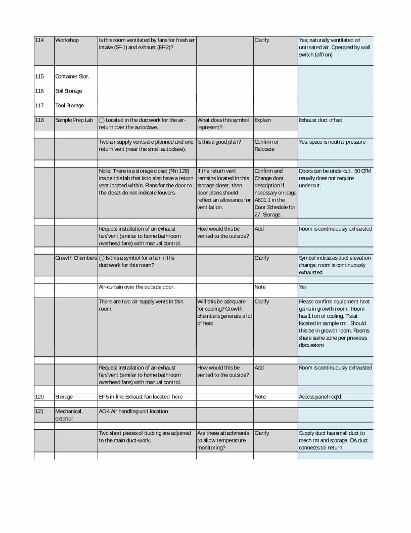
114 Workshop Is this room ventilated by fans for fresh airintake (SF-1) and exhaust (EF-2)?
Clarify Yes; naturally ventilated w/untreated air. Operated by wallswitch (off/on)
115 Container Stor.
116 Soil Storage
117 Tool Storage
118 Sample Prep Lab Located in the ductwork for the air-return over the autoclave.
What does this symbolrepresent?
Explain Exhaust duct offset
Two air supply vents are planned and onereturn vent (near the small autoclave).
Is this a good plan? Confirm orRelocate
Yes; space is neutral pressure
Note: There is a storage closet (Rm 129)inside this lab that is to also have a returnvent located within. Plans for the door tothe closet do not indicate louvers.
If the return ventremains located in thisstorage closet, thendoor plans shouldreflect an allowance forventilation.
Confirm andChange doordescription ifnecessary on pageA601.1 in theDoor Schedule for27, Storage.
Doors can be undercut. 50 CFMusually does not requireundercut.
Request installation of an exhaustfan/vent (similar to home bathroomoverhead fans) with manual control.
How would this bevented to the outside?
Add Room is continuously exhausted
Growth Chambers Is this a symbol for a fan in theductwork for this room?
Clarify Symbol indicates duct elevationchange; room is continuouslyexhausted
Air-curtain over the outside door. Note YesAir-curtain over the outside door. Note Yes
There are two air-supply vents in thisroom.
Will this be adequatefor cooling? Growthchambers generate a lotof heat.
Clarify Please confirm equipment heatgains in growth room. Roomhas 1 ton of ccoling. T'statlocated in sample rm. Shouldthis be in growth room. Roomsshare same zone per previousdiscussionsdiscussions
Request installation of an exhaustfan/vent (similar to home bathroomoverhead fans) with manual control.
How would this bevented to the outside?
Add Room is continuously exhausted
120 Storage EF-5 in-line Exhaust fan located here Note Access panel req'd
121 Mechanical, AC-4 Air handling unit location121 Mechanical,exterior
AC-4 Air handling unit location
Two short pieces of ducting are adjoinedto the main duct-work.
Are these attachmentsto allow temperaturemonitoring?
Clarify Supply duct has small duct tomech rm and storage. OA ductconnects toi return.
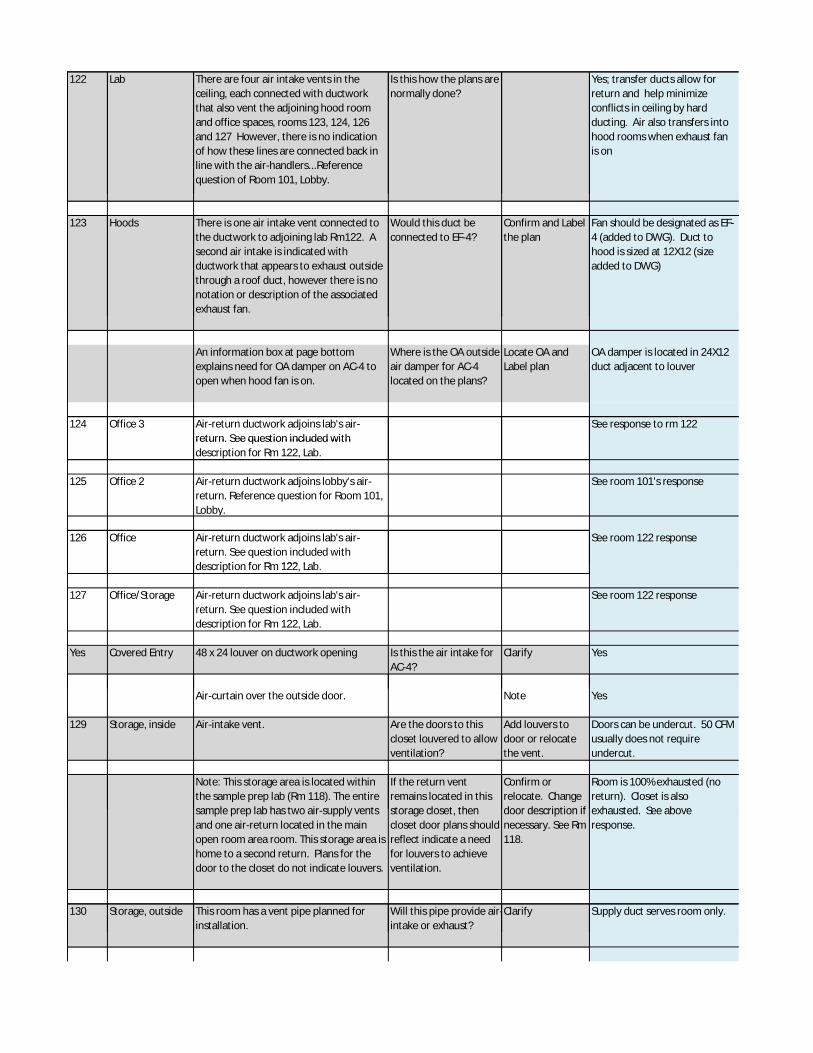
122 Lab There are four air intake vents in theceiling, each connected with ductworkthat also vent the adjoining hood roomand office spaces, rooms 123, 124, 126and 127 However, there is no indicationof how these lines are connected back inline with the air-handlers...Referencequestion of Room 101, Lobby.
Is this how the plans arenormally done?
Yes; transfer ducts allow forreturn and help minimizeconflicts in ceiling by hardducting. Air also transfers intohood rooms when exhaust fanis on
123 Hoods There is one air intake vent connected tothe ductwork to adjoining lab Rm122. Asecond air intake is indicated withductwork that appears to exhaust outsidethrough a roof duct, however there is nonotation or description of the associatedexhaust fan.
Would this duct beconnected to EF-4?
Confirm and Labelthe plan
Fan should be designated as EF-4 (added to DWG). Duct tohood is sized at 12X12 (sizeadded to DWG)
An information box at page bottomexplains need for OA damper on AC-4 toopen when hood fan is on.
Where is the OA outsideair damper for AC-4located on the plans?
Locate OA andLabel plan
OA damper is located in 24X12duct adjacent to louver
124 Office 3 Air-return ductwork adjoins lab's air-return. See question included with
See response to rm 122return. See question included withdescription for Rm 122, Lab.
125 Office 2 Air-return ductwork adjoins lobby's air-return. Reference question for Room 101,Lobby.
See room 101's response
126 Office Air-return ductwork adjoins lab's air-return. See question included withdescription for Rm 122, Lab.
See room 122 response
description for Rm 122, Lab.
127 Office/Storage Air-return ductwork adjoins lab's air-return. See question included withdescription for Rm 122, Lab.
See room 122 response
Yes Covered Entry 48 x 24 louver on ductwork opening Is this the air intake forAC-4?
Clarify Yes
Air-curtain over the outside door. Note Yes
129 Storage, inside Air-intake vent. Are the doors to thiscloset louvered to allowventilation?
Add louvers todoor or relocatethe vent.
Doors can be undercut. 50 CFMusually does not requireundercut.
Note: This storage area is located withinthe sample prep lab (Rm 118). The entiresample prep lab has two air-supply vents
If the return ventremains located in thisstorage closet, then
Confirm orrelocate. Changedoor description if
Room is 100% exhausted (noreturn). Closet is alsoexhausted. See abovesample prep lab has two air-supply vents
and one air-return located in the mainopen room area room. This storage area ishome to a second return. Plans for thedoor to the closet do not indicate louvers.
storage closet, thencloset door plans shouldreflect indicate a needfor louvers to achieveventilation.
door description ifnecessary. See Rm118.
exhausted. See aboveresponse.
130 Storage, outside This room has a vent pipe planned forinstallation.
Will this pipe provide air-intake or exhaust?
Clarify Supply duct serves room only.installation. intake or exhaust?

Exhaust fans had been planned for thisroom, but are not indicated in thisdrawing. 16" x 16" exhaust fan had beenplanned for installation in the west wall.
Would these fans posea problem for operationof the proposed ventpipe?
Confirm and ifacceptable, addexhaust fans tothis plan page.
Room is currently pressurizedwith conditioned air whichrelieves undercut doors.
131 Entry, east Air-curtain over the outside door. note
132 Mechanical Both AC-1 and AC-2 located here.132 MechanicalRoom, interior
Both AC-1 and AC-2 located here.
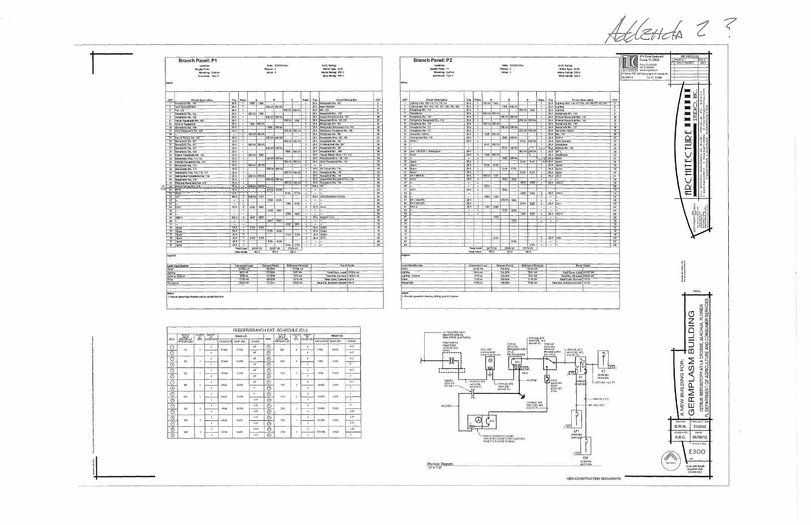
Branch Panel: P1 Loc:ntfon:
SUpply From:
Noles:
Mounting: Surface Endosure: Type 1
CKT Circuit Description 1 RoceptadeRm.125
Dc:rOper<ItOIOther
5 Rm.123 7 ROC!.'Jlllld!!Rm.123 9 Rcceph~deRm. 125
II PnnlerReceptlldeRm.I03
13 &1enorRoct"Pillde 15 Re<:t;lllldeRrn.1D-3 17 OV171 Reeeptade Rm. 105
19 -21 Faurei.S!71:;a-Rm.I05
Zl Rec~;JtlldeRm.107
25 Roceptnde:Rm.107 27 ROCf.'Jlll!deRm.107 2S Rec~;JllldeRm.1t>9
31 COpier Reo::eptade Rrn. 109
33 Rocept~deRms.111,112
35 Wnsher Reeeptnde Am. 114
6.117
5
Rm.118 a' .& 1 .11!1
55 LPI 57 -5S -fit CU-2
" 65 -67 EDH-1
tzgend;
I.DadCia-J:sii!C<~tlcn
HVAC
Ncttt~:
1.Pmvidlllyp!!'MiltB1d~ociOI'fsln\ingspeciflclocnboo,
:en
100
I~
l
1 r----;-l
1 r----;-l
1 r----;-
' 1 1---:;---
'I' ' 1 --;--
l
I~
JAW(;
Vchs: 121lr.!!.laWyc Phases:J
Trip Poles 20A 1 1000 lOA 20A
~A 1 :.WVA loo:l
20A
20A 1400 6001/A 20A 50 A
lOA 20A
- 100VA ~VA
:.'OA 600VA :!OOVA
20A :.WVA loo:l
lOA 20A ZtlA \ BOOVA 100VA
20A 200VA 400VA 2!lA lOA
_"!A -u
100A 3 BOOVA OVA
2760
20A OVA
20A 21JA ;.>OA OVA OVA
"'A Tct<lll.oad: 5J.U4VA
Toi<IIAmP'S: 452A
v.lres:4
!:OOVA 5001/A
aoovA :!!XI VA
1000 :?OOVA
500VA 600VA
6001/A 400VA
400VA 400VA
4001/A 500VA
!iOOVA 2001/A
49VA 22500
2760
OVA
OVA OVA
533171/A
451A
Cont~~::ded Load
mnoovA 4G73VA
1010VA
Demand Fodor 100.(}[)1{, 125.0\.1% 1ZS.o-J%
12719VA :msGOVA
!OO.o-J"l'o 57.51"~
..... 1
SOOVA 500VA 1
ZOOVA 1:00
tOO VA 200VA
600VA aoovA
1000 OOOVA
;_>[JQVA 100VA 2
tiOOVA tlOOVA
200VA 400VA 1
OVA 1m0
OVA
"'" 6667
OVA OVA
OVA OVA
47936VA
E,-JimllledOemand 10n00VA 5/J41VA
125JVA
127t&VA 19200VA
FEEDER/BRANCH CKT. SCHEDULE (CU)
G
l
A.LC.Rlii!ng: Mains Type.: MCB
Mal~ Rilling: SOOA MCB Ruling: 500 A
Trip Circuit 0esCI'fptlon 20 A Re:;eptndo Rm. 1Z7 20A tklcr0pG'ilta-
20A Rm.123 :.'0 A Re::eplade Rm. 124
20 A Cop11!f R~tade Rm. 103 20A RoceplliCieRms.103,125 20A ReceptadeRm.\01
20 A Rel'ngerntor Rcccptndc Rm. 105
20A MooWJtVeReceptadeRm.105 20A Recepl&:feRm.105
20 A Recept:lde Rm:;. 102, 105
:!lJA ReceplacleRm.107
20A TvRoceptadeRm. 107
ReceptocleRm.107
20A RecepladeRm. 109
20A F!1Ua~ISen$a- Rms.111, 112
20A RecrpltldeRm:<-110, 113 50 A c.-yer Re<:eptade Rm. 114
20A AJrCtr\alnRm.l\4
20A Recep!ocleRm.1t8
20 A Re::~t&IC! Rm. 118 20 A D.s11wa!:ller Recftllllde Rm. 118
20A RC!Ct'placfeRm.118
250A P2
150 A GREENHOUSE PN1El
40A AC-2
20A Sp!ll'e
21lA Sp!ll'e
20A Spnre
JOA SPD
TD1aiCon11. load: 1545!1\iVA
Total Ert Oemand: 1456J1 VA Total Conn. Current: 429A
Total Est. ~mand current 40/l A
G l~lll I 1-;-- II~~-·."'" ~~'ti':. I T -
1)/,V,'t;; 115/l
10
14
16
"' 22 24
" " " " 34
" 40
42 44
40
"' " 54 56
" " £4
" " 70 72 74 76 76
" "
Branch Panel: P2 Local. len:
Suppty'From: PI Mounting: surra~e
Enelosure: Type 1
CKT Circuit Description
•
100,110,111,112,114 101.102,103,104,1(o5,11.V;i,107,
119
7 Rm.119
11 AefngerntorR~q~tadeRm.119
13 Reo::ep!adeRm.119
-;~;
" -51 AC--t
53
55 -57 EF~1 (ROOF)
59 EF·2(ROOF)
61 VAV-3
6J -
65 -
"' 71 7J 75 77
" 01 6J
Lo3dC1a,IIIC<~tlon
HVAC UQtlUng UQ1111119~ Eli!!'IQ'
Not~:
1.PrtMdlltypewni!B1d~oclorysln!ing~ecificlocnboo.
Volts: 12012!:!!1 Wye
P"'*es: 3 ALC.RIIItng:
Mains Type: MCB
Mains Rilling: 250A MCSRatlng: 250A
Trip Poles ZOA 760VA 1642
:OA 26A 20A 1 SOOVA 400VA
21lA
20A
20A
Z!JA 20A
"" lOA
200VA 200VA
1500 500VA
OVA 400VA
1000
:.'OA OVA
20A
20A I 500VA 1245
20A
25A
26A
:OA
zaso t3'JJ
20A 1167
133J
Total load: 22174 VA
Tc!OJ!Amps: 1WA
v.lrn:4
1398 69SVA
400VA 200VA
200VA :.:OOVA
2500 670VA
OVA 100VA
1800 5COVA
OVA OVA
2933 1245
2880
670VA 1333
1167 2200
133J
OVA
225llilVA
19JA
Conn~cted Load 45·126VA 4673VA
1010VA
DcmandFaclor 100.00% \25.00';(, 125.00",(,
71701/A 4160VA
\llO.OO% 100.00%
400VA 1203
200VA ::OOVA
200VA 500VA
OVA 5001/A
360VA 661/A
OVA OVA
29:lJ 1500
2&!0
OVA "~"'80
tm6VA 148A
Poles Trip Circuit De9crlptlon 1 20A LlgtJhll{l Rm:<-116,117,116,119,120,121.126,130 1 2DA Llgt\llng
Llgt\Ung 20A Rea-ptade Rm. 11!!
20A Frl'l!.:'erAI!C('ptaciC!Rm.119
20A FreezerReceptacleRm.119 20 A Aea-pt~:~de Rm. 120
RccqJt!ldeRm.121 20A Geflenlt(lJ'Hettler
::.Rm.114 OQA
lOA .130
"' 20A R ptncle 20
1-=: 20A Spa~
I Spme 20A span: 20A spare 15A AC--3
20A VAV-2
:2DA
30A CU.\
20A VAVJ,
SPD
E$\lmatedDemnnd
45426VA ~841VA
1::63VA
Panc\Tctals
Tctill Ct»lll. lead: 62457 VA Total Ea Demand; D.lll82 VA
7170VA 4160VA
Total conn. curren1: 173 A
Total Est, Demand Current: 177 A
GH1
CKT
'
" 16 18 21!
" " " " "
'" 50 5.2
" 56
"
" 70 72 74
70
"
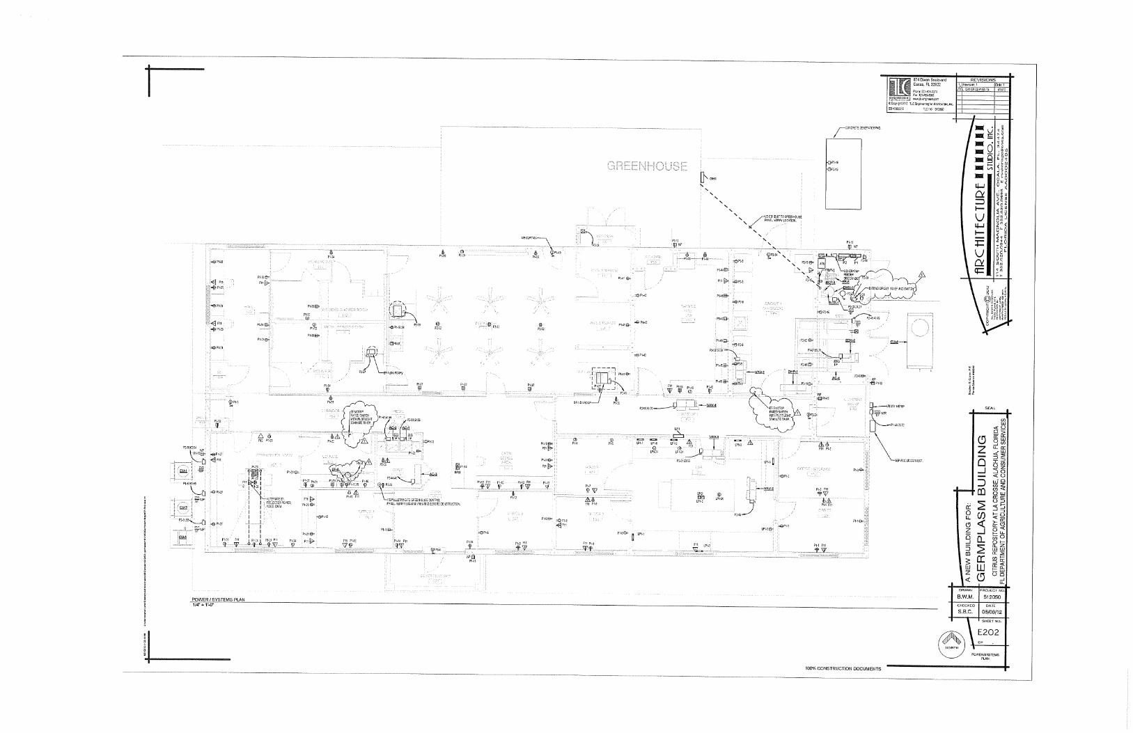
100% CONSTRUCTION DOCUMENTS
ll740ixonBoukward Cocoa, FL3::!9:!2
FnJ·,t-~~1-~t-e:i~ Fnll\..U;..d'-"0
f.':~~~.~-[.~!~.~ w~~-l;-t,~,em~~ CCt;r-;:'1:1-:t; TLCEf9r-H~Il!J'OrAt:.'lr.K:!n.lrl:.
:::1:::00::15 ftC JIG 51~05\1
REVISIONS 1 R=San 1 Ou!e 1
I Cf'!l::'l C'JV1J8iTS :11:11~
I
SEAL
B.W.M. 512050
CHC:CKt:D
S.B.C. 06/08/12
E300
ONE UNE FJSER DIAGRAM AND SCHEDUlES
SUMMARY REPORT OF A
GEOTECHNICAL SITE EXPLORATION
LACROSSE CITRUS REPOSITORY LACROSSE, ALACHUA COUNTY, FLORIDA
GSE PROJECT No. 11248
Prepared For: BUREAU OF CITRUS BUDWOOD REGISTRATION
SEPTEMBER 2011
Certificate of Authorization No. 27430
GSE Engineering & Consulting, Inc. 5590 SW 64th Street, Suite B Gainesville, Florida 32608
352-377-3233 Phone 352-377-0335 Fax
www.gseengineering.com Certificate of Authorization No. 27430
September 8, 2011
Mr. F. Benjamin Rosson, CCA Operations and Management Consultant II Bureau of Citrus Budwood Registration 9870 NW 42nd Court Chiefland, Florida 32626
Subject: Summary Report of a Geotechnical Site Exploration LaCrosse Citrus Repository LaCrosse, Alachua County, Florida GSE Project No. 11248
Dear Mr. Rosson:
GSE Engineering & Consulting, Inc. (GSE) is pleased to submit this geotechnical site exploration report for the above referenced project. Presented herein are the findings and conclusions of our exploration, including the geotechnical parameters and recommendations for stormwater management, pavement, and building foundation designs. We appreciate this opportunity to have assisted you on this project. If you have any questions or comments concerning this report, please contact us.
Sincerely,
GSE Engineering & Consulting, Inc.
Kenneth L. Hill, P.E. Jesse J. Jannette, E.I. Principal Engineer Staff Engineer Florida Registration Number 40146 KLH/jjj:ts Z:Projects\11248 LaCrosse Citrus Repository/11248.doc Distribution: Addressee (1)
File (1)
Summary Report of a Geotechnical Site Exploration September 8, 2011 LaCrosse Citrus Repository LaCrosse, Alachua County, Florida GSE Project No. 11248
ii
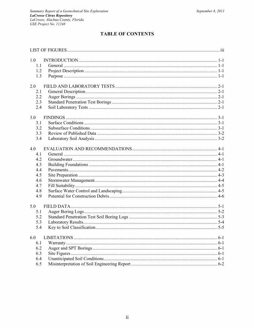
TABLE OF CONTENTS
LIST OF FIGURES ..................................................................................................................................... iii
1.0 INTRODUCTION ......................................................................................................................... 1-1 1.1 General ...................................................................................................................................... 1-1 1.2 Project Description .................................................................................................................... 1-1 1.3 Purpose ...................................................................................................................................... 1-1
2.0 FIELD AND LABORATORY TESTS ......................................................................................... 2-1 2.1 General Description ................................................................................................................... 2-1 2.2 Auger Borings ........................................................................................................................... 2-1 2.3 Standard Penetration Test Borings ............................................................................................ 2-1 2.4 Soil Laboratory Tests ................................................................................................................ 2-1
3.0 FINDINGS .................................................................................................................................... 3-1 3.1 Surface Conditions .................................................................................................................... 3-1 3.2 Subsurface Conditions ............................................................................................................... 3-1 3.3 Review of Published Data ......................................................................................................... 3-2 3.4 Laboratory Soil Analysis ........................................................................................................... 3-2
4.0 EVALUATION AND RECOMMENDATIONS .......................................................................... 4-1 4.1 General ...................................................................................................................................... 4-1 4.2 Groundwater .............................................................................................................................. 4-1 4.3 Building Foundations ................................................................................................................ 4-1 4.4 Pavements .................................................................................................................................. 4-2 4.5 Site Preparation ......................................................................................................................... 4-3 4.6 Stormwater Management ........................................................................................................... 4-4 4.7 Fill Suitability ............................................................................................................................ 4-5 4.8 Surface Water Control and Landscaping ................................................................................... 4-5 4.9 Potential for Construction Debris .............................................................................................. 4-6
5.0 FIELD DATA ................................................................................................................................ 5-1 5.1 Auger Boring Logs .................................................................................................................... 5-2 5.2 Standard Penetration Test Soil Boring Logs ............................................................................. 5-3 5.3 Laboratory Results ..................................................................................................................... 5-4 5.4 Key to Soil Classification .......................................................................................................... 5-5
6.0 LIMITATIONS ............................................................................................................................. 6-1 6.1 Warranty .................................................................................................................................... 6-1 6.2 Auger and SPT Borings ............................................................................................................. 6-1 6.3 Site Figures ................................................................................................................................ 6-1 6.4 Unanticipated Soil Conditions ................................................................................................... 6-1 6.5 Misinterpretation of Soil Engineering Report ........................................................................... 6-2

Summary Report of a Geotechnical Site Exploration September 8, 2011 LaCrosse Citrus Repository LaCrosse, Alachua County, Florida GSE Project No. 11248
iii
LIST OF FIGURES
Figure
1. Project Site Location Map
2. Site Plan Showing Approximate Locations of Field Tests
Summary Report of a Geotechnical Site Exploration September 8, 2011 LaCrosse Citrus Repository LaCrosse, Alachua County, Florida GSE Project No. 11248
1-1
1.0 INTRODUCTION
1.1 General
GSE Engineering & Consulting, Inc. (GSE) has completed this geotechnical exploration for the proposed LaCrosse Citrus Repository located in LaCrosse, Alachua County, Florida. Our exploration was performed in accordance with GSE Proposal No. 2011-137 dated July 20, 2011. You authorized our services on July 28, 2011.
1.2 Project Description
We understand this project will consist of office buildings and greenhouses located in LaCrosse, Alachua County, Florida. The site is located along the west side of State Road 121 in the north portion of LaCrosse, Florida. Figure 1 illustrates the project location.
You furnished us with a preliminary site plan showing the proposed building layouts and locations along with information about the project. We understand that the project will include a Budwood office building, Germplasm office building, two greenhouses, a driveway and parking lot, and a stormwater management facility.
The office buildings are expected to be single-story, concrete masonry unit (CMU) construction, and the greenhouses are expected to be pre-engineered, steel frame construction. The Germplasm greenhouse will have a concrete floor, while the larger greenhouse will not.
The Budwood structure will have an approximate footprint of 132 by 132 feet. The Germplasm office will have dimensions of about 48 by 105 feet. Structural loads of 2 to 3 kips per linear foot for walls and up to 30 kips for columns are anticipated. We anticipate the finished floor will be constructed within 2 feet of the existing grades.
The greenhouse structures will be open-air, steel frame construction. Column loads of up to 50 kips are anticipated. The Germplasm greenhouse will have an area of about 24,000 square feet, and the larger greenhouse will have an area of about 60,500 square feet.
You provided a preliminary site plan indicating the location of the proposed office buildings and greenhouses, driveway, parking lot, and stormwater management facility. In addition, a recent aerial photograph was also obtained and reviewed. We used the provided site plan and aerial photograph in the preparation of this exploration and report.
1.3 Purpose The purpose of this geotechnical exploration was to determine the general subsurface conditions, evaluate these conditions with respect to the proposed construction, and prepare geotechnical recommendations to assist in the design of the building foundations, pavements, and stormwater management facility.
Summary Report of a Geotechnical Site Exploration September 8, 2011 LaCrosse Citrus Repository LaCrosse, Alachua County, Florida GSE Project No. 11248
2-1
2.0 FIELD AND LABORATORY TESTS
2.1 General Description
The procedures used for field sampling and testing are in general accordance with industry standards of care and established geotechnical engineering practices for this geographic region. Our exploration consisted of performing eleven (11) Standard Penetration Test (SPT) borings to depths of 20 feet below land surface (bls) and four (4) auger borings to depths of 10 feet bls within the proposed building areas, three (3) auger borings to depths of 5 feet bls within the driveway and parking lot, and five (5) auger borings to depths of 15 feet bls within the area of the stormwater management facility.
The soil borings were performed at the approximate locations as shown on Figure 2. We located the borings at the site using the provided site plan and obvious site features as reference. You should consider the locations approximate. The soil borings were performed between the dates of August 22, 2011 and August 25, 2011.
2.2 Auger Borings
The auger borings were performed in accordance with ASTM Specification D-1452. The borings were performed with flight auger equipment that was rotated into the ground in a manner that reduces soil disturbance. After penetrating to the required depth, the auger was retracted and the soils collected on the auger flights or from the auger bucket were field classified and placed in sealed containers. Representative samples of each stratum were retained from the auger boring. Results from the auger borings are provided in Section 5.2.
2.3 Standard Penetration Test Borings
The soil borings were performed with a drill rig employing mud rotary drilling techniques and Standard Penetration Testing (SPT) in accordance with ASTM Specifications D-1586. The SPTs were performed continuously to 10 feet and at 5-foot intervals thereafter. Soil samples were obtained at the depths where the SPTs were performed. The soil samples were classified in the field, placed in sealed containers, and returned to our laboratory for further evaluation.
After drilling to the sampling depth and flushing the borehole, the standard two-inch O.D. split-barrel sampler was seated by driving it 6 inches into the undisturbed soil. Then the sampler was driven an additional 12 inches by blows of a 140-pound hammer falling 30 inches. The number of blows required to produce the next 12 inches of penetration were recorded as the penetration resistance (N-value). These values and the complete SPT boring logs are provided in Section 5.1.
Upon completion of the sampling, the boreholes were abandoned in accordance with Water Management District guidelines.
2.4 Soil Laboratory Tests
The soil samples recovered from the soil borings were returned to our laboratory, and examined to confirm the field descriptions. Representative samples were then selected for laboratory testing. The laboratory tests consisted of seven (7) percent soil fines passing the No. 200 sieve

Summary Report of a Geotechnical Site Exploration September 8, 2011 LaCrosse Citrus Repository LaCrosse, Alachua County, Florida GSE Project No. 11248
2-2
determinations with natural moisture contents and three (3) constant head permeability tests. These tests were performed in order to aid in classifying the soils and to further evaluate their engineering properties. The laboratory tests are provided in Section 5.3.
Summary Report of a Geotechnical Site Exploration September 8, 2011 LaCrosse Citrus Repository LaCrosse, Alachua County, Florida GSE Project No. 11248
3-1
3.0 FINDINGS
3.1 Surface Conditions
Messrs. Jesse J. Jannette E.I. and Jason E. Gowland, P.E. visited the site on August 15, 2011 to observe the site conditions and mark the boring locations.
We understand the parcel was recently cleared. The site is mostly open grass and weed covered. Small to large trees are scattered along the perimeter of the site. Burned debris was observed at the surface in a few areas of the site. The eastern side of the site is bordered by State Road 121. The western side of the site is bordered by Old State Road 121-A (abandoned). An existing fire tower is located in the northwestern portion of the property. A wooden fenced-in area is located at the northern extent of the parcel. The preliminary site plan indicates underground propane tanks are located in the western to northwestern portion of the site.
The topography at the site is gently sloping downward from west to east with the regional topography being gently sloping downward to the northeast. The LaCrosse USGS Topographic Map indicates the ground surface elevations at the site are near elevations 125 to 135 feet1 NGVD.
3.2 Subsurface Conditions
The locations of the SPT and auger borings are provided on Figure 2. Complete logs for the borings are provided in Sections 5.1 and 5.2. Descriptions for the soils encountered are accompanied by the Unified Soil Classification System symbol (SM, SP-SM, etc.) and are based on visual examination of the recovered soil samples and the laboratory tests performed. Stratification boundaries between the soil types should be considered approximate, as the actual transition between soil types may be gradual.
The SPT and auger borings indicate the soil conditions across the site are relatively consistent. The auger borings performed in the proposed building, driveway, parking lot, and stormwater management facility areas encountered sand with silt (SP-SM) and silty sand (SM) to the respective boring termination depths.
The SPT borings performed within the proposed building areas generally encountered sand with silt (SP-SM) and silty sand (SM) in the upper 12 to 19 feet bls. These surficial soils were underlain by silty sand with clay (SM-SC) to the 20 feet bls boring termination depth in borings B-2, B-5, B-7, B-8, B-9, and B-10. SPT boring B-1 encountered clayey sand (SC) underlying the silty sand with clay (SM-SC) layer. The surficial sand with silt (SP-SM) and silty sand (SM) strata were underlain by sandy clay to clay with sand (CL/CH) to the 20 feet bls boring termination depth in borings B-3, B-4, B-6, and B-11.
The SPTs performed indicate the surficial sand with silt (SP-SM) and silty sand (SM) encountered to depths ranging from approximately 12 to 19 feet bls are generally in a loose to medium dense strength soil condition with N-values ranging from 4 to 29 blows per foot. 1 DeLorme Topo USA® 6.0, Alachua Quadrangle, 1981.
Summary Report of a Geotechnical Site Exploration September 8, 2011 LaCrosse Citrus Repository LaCrosse, Alachua County, Florida GSE Project No. 11248
3-2
Isolated very loose soil conditions were encountered within the silty sand (SM) stratum in B-1 and B-7. The underlying silty sand with clay (SM-SC) is generally in a loose to dense condition, with N-values of 7 to 35 blows per foot. The exception occurred in B-8, which encountered very dense silty sand with clay (SM-SC) with an N-value of 70 blows per foot. The clayey sand (SC) encountered from approximately 17 to 20 feet bls in B-1 is medium dense, with an N-value of 29 blows per foot. The deeper sandy clay to clay with sand (CL/CH) encountered in borings B-3, B-4, B-6, and B-11 is stiff to very stiff, with N-values ranging from 12 to 22 blows per foot.
The groundwater table was encountered in each of the SPT borings and in auger borings A-1 through A-4 and P-1 through P-5 at depths ranging from approximately 4 to 5.5 feet bls at the time of our exploration. The groundwater table was not encountered in the driveway and parking lot auger borings (R-1, R-2, and R-3).
3.3 Review of Published Data
The Soil Conservation Service (SCS) Soil Survey for Alachua County2 maps one soil series in the general vicinity of the site consisting of Zolfo sand. The following soil description is from the Soil Survey.
Zolfo sand – This nearly level, somewhat poorly drained soil is on slight rises of the flatwoods and in the rather broad transitional area between the rolling uplands of the western part of the county and the flatwoods of the eastern part. Slopes are nearly level and range from 0 to 2 percent. The areas are irregular in shape and range from 25 to 75 acres. Typically, the surface layer is dark gray sand about 8 inches thick. The subsurface layer is sand and extends to a depth of 60 inches. The upper 6 inches is grayish brown; the next 20 inches is pale brown with mottles; and the lower 26 inches is very pale brown and has mottles. The subsoil is dark brown to dark reddish brown sand to a depth of 82 inches or more. Included with this soil in mapping are small areas of Chipley, Pottsburg, Sparr, and Tavares soils. Also included are small areas of soils that are similar to the Zolfo soil, but have a water table at a depth of 40 to 72 inches during wet periods. Total included areas are about 15 percent or less.
This Zolfo soil has a water table that is at a depth of 24 to 40 inches for 2 to 6 months during most years and may be at a depth of 10 to 24 inches for periods of about 2 weeks or less during very wet periods. Surface runoff is slow. The available water capacity is low to medium to a depth of 60 inches and medium to high below this depth. Permeability is rapid to a depth of 60 inches and moderate below. Natural fertility is low. Organic matter content of the surface layer is low.
3.4 Laboratory Soil Analysis
Selected soil samples recovered from the soil borings were analyzed for natural moisture content, the percent fines passing the No. 200 sieve and vertical permeability. Selected soil samples were 2 Soil Survey of Suwannee County, Florida. Soil Conservation Service, U.S. Department of Agriculture.

Summary Report of a Geotechnical Site Exploration September 8, 2011 LaCrosse Citrus Repository LaCrosse, Alachua County, Florida GSE Project No. 11248
3-3
collected from depths ranging from 2 to 10 feet bls. These tests were performed to confirm visual soil classification and evaluate their engineering properties. The complete laboratory report is provided in Section 5.3.
The laboratory tests indicate the tested soils consist of sand with silt (SP-SM). The sand with silt (SP-SM) had approximately 5.8 to 8.4 percent soil fines passing the No. 200 sieve and moisture contents of 8.7 to 19 percent.
The constant head permeability test results indicate the surficial sand with silt (SP-SM) has vertical coefficients of permeability on the order of 4 to 9 feet per day (1.30 x 10⁻³ to 3.34 x 10⁻³ cm/sec).
Summary Report of a Geotechnical Site Exploration September 8, 2011 LaCrosse Citrus Repository LaCrosse, Alachua County, Florida GSE Project No. 11248
4-1
4.0 EVALUATION AND RECOMMENDATIONS
4.1 General
The following recommendations are made based upon our understanding of the proposed construction, a review of the attached soil borings and laboratory test data, and experience with similar projects and subsurface conditions. If plans or the location of proposed construction changes from those discussed previously, we request the opportunity to review and possibly amend our recommendations with respect to those changes.
In this section of the report, we present our recommendations for building foundations, pavements, stormwater management design, and our general site preparation guidelines.
4.2 Groundwater
The groundwater table was encountered in each of the SPT borings and in auger borings A-1 through A-4 and P-1 through P-5 at depths ranging from approximately 4 to 5.5 feet bls at the time of our exploration. We anticipate the normal seasonal high water table to be at depths of approximately 2 to 3.5 feet bls.
Temporary dewatering may be required for deep excavations and utilities. If construction proceeds during the wet season, we anticipate dewatering can be accomplished with underdrain pipes or well points connected to vacuum pumps. Localized dewatering can also be accomplished with sumps placed just outside the construction areas.
4.3 Building Foundations
The soil borings within the proposed building footprint indicate the soils at the site are consistent. The borings indicate approximately 12 to 19 feet of sand with silt (SP-SM) and silty sand (SM) overlying silty sand with clay (SM-SC), clayey sand (SC), and sandy clay to clay with sand (CL/CH).
Based upon the soil conditions encountered, we recommend the buildings be supported by conventional, shallow spread foundations. We recommend the shallow foundations be designed for a maximum net soil bearing pressure of 2,000 psf. Net bearing pressure is defined as the soil bearing pressure at the base of the foundation in excess of the natural overburden pressure. The foundations should be designed based upon the maximum load that could be imposed by all loading conditions.
The foundations should be embedded a minimum of 18 inches below the lowest adjacent grade. Interior foundations or thickened sections should be embedded a minimum of 12 inches. The foundations should have minimum widths of 18 inches for strip footings, and 24 inches for columns, even though the maximum soil bearing pressure may not be fully developed. The upper 24 inches of the bearing surface should be compacted to 95 percent of the Modified Proctor maximum dry density (ASTM D 1557).
Summary Report of a Geotechnical Site Exploration September 8, 2011 LaCrosse Citrus Repository LaCrosse, Alachua County, Florida GSE Project No. 11248
4-2
Due to the mostly sandy nature of the majority of the near-surface soils, we expect settlement to be mostly elastic in nature. The majority of the settlement will occur on application of the loads, during and immediately following construction. Using the recommended maximum bearing pressure, the assumed maximum structural loads, and the field and laboratory test data which we have correlated into the strength and compressibility characteristics of the subsurface soils, we estimate the total settlements of the structure to be 1 inch or less, with approximately half of it occurring upon load application (during construction).
Differential settlement results from differences in applied bearing pressures and the variations in the compressibility characteristics of the subsurface soils. For the building pad prepared as recommended, we anticipate differential settlement of less than 1/2 inch.
Post-construction settlement of the structures will be influenced by several interrelated factors, such as (1) subsurface stratification and strength/compressibility characteristics of the bearing soils; (2) footing size, bearing level, applied loads, and resulting bearing pressures beneath the foundation; (3) site preparation and earthwork construction techniques used by the contractor, and (4) external factors, including but not limited to vibration from off-site sources and groundwater fluctuations beyond those normally anticipated for the naturally-occurring site and soil conditions which are present.
Our settlement estimates for the structure are based upon the use of successful adherence to the site preparation recommendations presented later in this report. Any deviation from these recommendations could result in an increase in the estimated post-construction settlement of the structure.
4.4 Pavements
Overall soil conditions encountered by our borings at this site are suitable for supporting conventional limerock base and asphalt wearing surface pavements. We recommend a minimum 2 foot separation between the bottom of the pavement base course and the estimated seasonal high water table. Is this separation cannot be maintained, we recommend underdrains be considered to lower the water table. We have not been provided the anticipated traffic loading conditions; therefore, the following pavement component recommendations should be used only as guidelines.
4.4.1 Stabilized Subgrade
The stabilized subgrade should have a minimum Limerock Bearing Ratio (LBR) of 40, with minimum thicknesses of 6 inches for automobile parking lots and 12 inches for the entrance driveway. The stabilized subgrade can be imported material or a mixture of imported and on-site material. If a mix is proposed, a mix design should be performed to determine the optimum mix proportions. The stabilized subgrade should be compacted to a minimum of 98 percent of the Modified Proctor maximum dry density (ASTM D-1557) for soils with less than 15 percent fines content. Soils with 15 percent or greater fines content should be compacted to 100 percent of the Standard Proctor maximum dry density (ASTM D-698).
Summary Report of a Geotechnical Site Exploration September 8, 2011 LaCrosse Citrus Repository LaCrosse, Alachua County, Florida GSE Project No. 11248
4-3
4.4.2 Base Course
The base course should consist of crushed limerock having a LBR of at least 100. Limerock should be obtained from a FDOT approved source, and should meet FDOT gradation requirements. The base course thickness should be a minimum of 6 inches in automobile parking areas, and 8 inches in driveway areas. The base course should be compacted to at least 98 percent of the Modified Proctor maximum dry density (ASTM D-1557).
4.4.3 Wearing Surface
The asphalt-wearing surface should consist of an FDOT Type SP Hot Mix Asphalt mixture. For automobile parking lots, the thickness should be at least 1.5 inches. For the driveways, the thickness should be at least 2.0 inches and consist of an SP-12.5 mix. The asphalt should be compacted to at least 95 percent of the mix design density.
4.5 Site Preparation
The soils at this site should be suitable for supporting the proposed construction using normal, good practice site preparation procedures.
4.5.1 Stripping
Strip the construction limits and 10 feet beyond the perimeter of all grass, roots, topsoil, pavement, burnt debris, and other deleterious materials. You should expect to strip to depths of 6 to 12 or more inches. Deeper stripping may be necessary if major root systems are present and went undetected as part of this investigation.
4.5.2 Dewatering
Temporary dewatering may be required for deep excavations and utilities. If construction proceeds during the wet season, we anticipate dewatering can be accomplished with underdrain pipes or well points connected to vacuum pumps. Localized dewatering can also be accomplished with sumps placed just outside the construction areas.
In any case, the site should always be graded to promote runoff and limit the amount of ponding. Localized ponding of stormwater is expected without proper grading during construction, and could render previously acceptable surfaces unacceptable.
4.5.3 Proof-Rolling
Proof-roll the subgrade with heavy rubber-tired equipment, such as a loaded front-end loader or dump truck, to identify any loose or soft zones not found by the soil borings. The proof-rolling should be monitored by a geotechnical engineer or qualified technician. If compaction cannot be achieved, undercut or otherwise treat these zones as recommended by the geotechnical engineer in this report.
Summary Report of a Geotechnical Site Exploration September 8, 2011 LaCrosse Citrus Repository LaCrosse, Alachua County, Florida GSE Project No. 11248
4-4
4.5.4 Proof Compaction
Compact the subgrade to a density of at least 95 percent of the Modified Proctor maximum dry density (ASTM Specification D-1557). The specified compaction should be obtained to a depth of 2 foot below the foundation bottoms and the existing grade prior to placing fill.
4.5.5 Fill Placement
Imported fill placed to raise the site grades should consist of clean sand having less than 10 percent passing the No. 200 sieve. On-site soils meeting the requirements of Section 4.7 may also be used as structural fill. The fill should be placed in maximum 12-inch loose lifts that are compacted to at least 95 percent of the Modified Proctor maximum dry density. If lighter “walk-behind” compaction equipment is used, this may require lifts of 4 inches or less to achieve the required degree of compaction.
4.5.6 Testing
Perform compaction testing in the subgrade and fill. One test should be performed every 50 linear feet of continuous footing and every other column footing, per foot depth of fill or native material. Perform a compaction test for each 2,500 square feet of floor area or 10,000 square feet of pavement area per foot of fill or native material, or a minimum of three tests each, whichever is greater. Test all footing excavations to a depth of 2 feet, at the frequencies stated above.
4.6 Stormwater Management
The soil conditions at the stormwater management facility are consistent with the building and parking borings. The borings encountered surficial sand with silt (SP-SM) and silty sand (SM) to the 15 feet bls boring termination depth.
The water table was encountered in the pond borings (P-1 through P-5) at depths of approximately 4 to 5 feet bls at the time of our exploration. We estimate the normal seasonal high water table at the site to vary from approximately 2 to 3.5 feet bls. We anticipate the normal seasonal high water table in the pond borings to be at approximately 2 to 2.5 feet bls. Considering the results of the auger borings performed in the stormwater management facility, coupled with the information provided in the soil survey and dry conditions experienced by the Alachua County area over the past several months, the water table encountered at the time of our site exploration is likely near the seasonal low water table. Therefore, we expect the normal seasonal low water table to be at approximate depths of 4 to 5 feet bls.
The laboratory permeability tests indicate the surficial layer of sand with silt (SP-SM) has vertical coefficients of permeability of 4 to 9 feet per day.
Based upon our findings and test results, our recommended soil and groundwater parameters for the proposed stormwater management area improvements are presented below. The recommended parameters consider the results of the permeability tests and wash 200 determinations, the permeability characteristics of the in situ materials, and our experience with these types of soils.
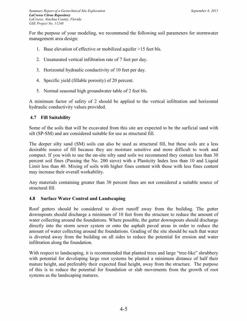
Summary Report of a Geotechnical Site Exploration September 8, 2011 LaCrosse Citrus Repository LaCrosse, Alachua County, Florida GSE Project No. 11248
4-5
For the purpose of your modeling, we recommend the following soil parameters for stormwater management area design:
1. Base elevation of effective or mobilized aquifer >15 feet bls.
2. Unsaturated vertical infiltration rate of 7 feet per day.
3. Horizontal hydraulic conductivity of 10 feet per day.
4. Specific yield (fillable porosity) of 20 percent.
5. Normal seasonal high groundwater table of 2 feet bls.
A minimum factor of safety of 2 should be applied to the vertical infiltration and horizontal hydraulic conductivity values provided.
4.7 Fill Suitability
Some of the soils that will be excavated from this site are expected to be the surficial sand with silt (SP-SM) and are considered suitable for use as structural fill.
The deeper silty sand (SM) soils can also be used as structural fill, but these soils are a less desirable source of fill because they are moisture sensitive and more difficult to work and compact. If you wish to use the on-site silty sand soils we recommend they contain less than 30 percent soil fines (Passing the No. 200 sieve) with a Plasticity Index less than 10 and Liquid Limit less than 40. Mixing of soils with higher fines content with those with less fines content may increase their overall workability.
Any materials containing greater than 30 percent fines are not considered a suitable source of structural fill.
4.8 Surface Water Control and Landscaping
Roof gutters should be considered to divert runoff away from the building. The gutter downspouts should discharge a minimum of 10 feet from the structure to reduce the amount of water collecting around the foundations. Where possible, the gutter downspouts should discharge directly into the storm sewer system or onto the asphalt paved areas in order to reduce the amount of water collecting around the foundations. Grading of the site should be such that water is diverted away from the building on all sides to reduce the potential for erosion and water infiltration along the foundation.
With respect to landscaping, it is recommended that planted trees and large “tree-like” shrubbery with potential for developing large root systems be planted a minimum distance of half their mature height, and preferably their expected final height, away from the structure. The purpose of this is to reduce the potential for foundation or slab movements from the growth of root systems as the landscaping matures.

Summary Report of a Geotechnical Site Exploration September 8, 2011 LaCrosse Citrus Repository LaCrosse, Alachua County, Florida GSE Project No. 11248
4-6
Consideration should also be given to using landscaping that has a low water demand, so that excessive irrigation is not conducted around the structures.
4.9 Potential for Construction Debris During our site visit trace amounts of asphalt and burned debris were observed on the surface of the site within the proposed building pad area. Our geotechnical exploration found no indicators of buried construction debris at the soil boring locations. However, if asphalt debris is observed during stripping and grubbing operations it should be removed from within the building and roadway limits.

Summary Report of a Geotechnical Site Exploration September 8, 2011 LaCrosse Citrus Repository LaCrosse, Alachua County, Florida GSE Project No. 11248
5-1
5.0 FIELD DATA

Summary Report of a Geotechnical Site Exploration September 8, 2011 LaCrosse Citrus Repository LaCrosse, Alachua County, Florida GSE Project No. 11248
5-2
5.1 Auger Boring Logs
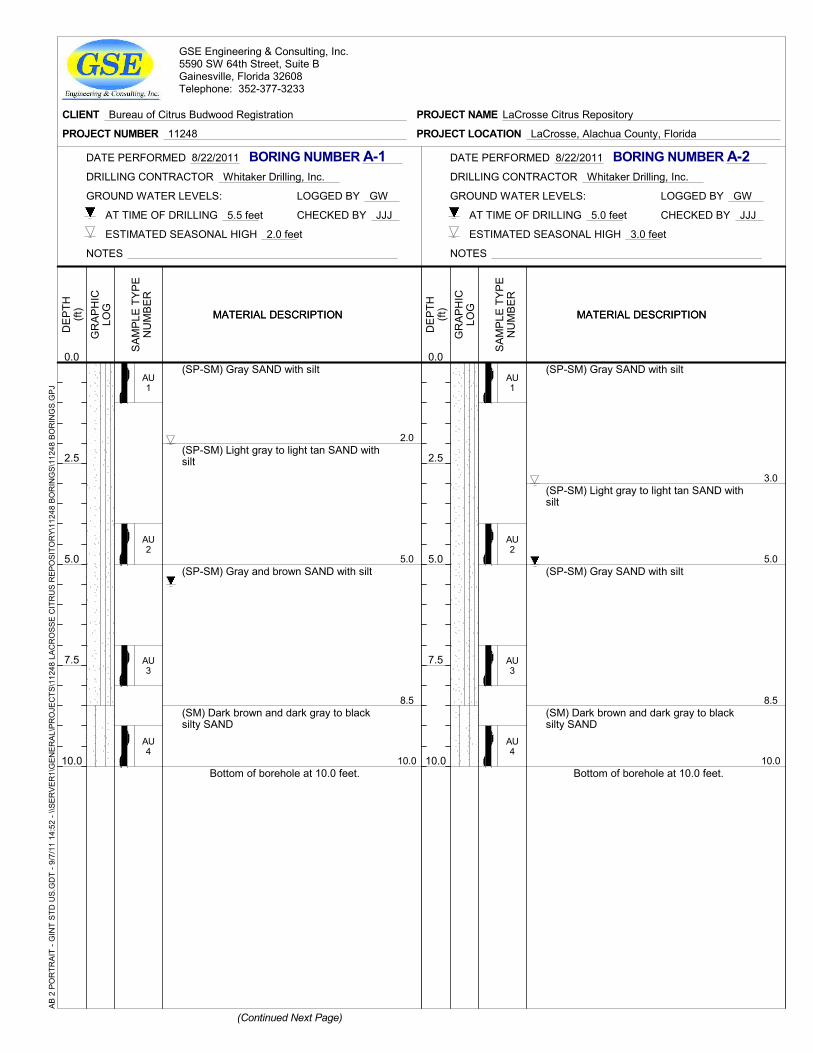
2.0
5.0
8.5
10.0
(SP-SM) Gray SAND with silt
(SP-SM) Light gray to light tan SAND withsilt
(SP-SM) Gray and brown SAND with silt
(SM) Dark brown and dark gray to blacksilty SAND
Bottom of borehole at 10.0 feet.
AU1
AU2
AU3
AU4
GR
AP
HIC
LOG
DE
PTH
(ft)
0.0
2.5
5.0
7.5
10.0
MATERIAL DESCRIPTIONMATERIAL DESCRIPTION
SA
MP
LE T
YP
EN
UM
BE
R
GROUND WATER LEVELS:
CHECKED BY JJJ
LOGGED BY GW
NOTES
AT TIME OF DRILLING 5.5 feet
DRILLING CONTRACTOR Whitaker Drilling, Inc.
BORING NUMBER A-1
ESTIMATED SEASONAL HIGH 2.0 feet
DATE PERFORMED 8/22/2011
(Continued Next Page)
CLIENT Bureau of Citrus Budwood Registration
PROJECT NUMBER 11248 PROJECT LOCATION LaCrosse, Alachua County, Florida
PROJECT NAME LaCrosse Citrus Repository
GSE Engineering & Consulting, Inc.5590 SW 64th Street, Suite BGainesville, Florida 32608Telephone: 352-377-3233
AB 2
PO
RTR
AIT
- GIN
T ST
D U
S.G
DT
- 9/7
/11
14:5
2 - \
\SER
VER
1\G
ENER
AL\P
RO
JEC
TS\1
1248
LAC
RO
SSE
CIT
RU
S R
EPO
SITO
RY\
1124
8 BO
RIN
GS\
1124
8 BO
RIN
GS.
GPJ
3.0
5.0
8.5
10.0
(SP-SM) Gray SAND with silt
(SP-SM) Light gray to light tan SAND withsilt
(SP-SM) Gray SAND with silt
(SM) Dark brown and dark gray to blacksilty SAND
Bottom of borehole at 10.0 feet.
AU1
AU2
AU3
AU4
GR
AP
HIC
LOG
DE
PTH
(ft)
0.0
2.5
5.0
7.5
10.0
MATERIAL DESCRIPTIONMATERIAL DESCRIPTION
SA
MP
LE T
YP
EN
UM
BE
R
GROUND WATER LEVELS:
CHECKED BY JJJ
LOGGED BY GW
NOTES
AT TIME OF DRILLING 5.0 feet
DRILLING CONTRACTOR Whitaker Drilling, Inc.
BORING NUMBER A-2
ESTIMATED SEASONAL HIGH 3.0 feet
DATE PERFORMED 8/22/2011
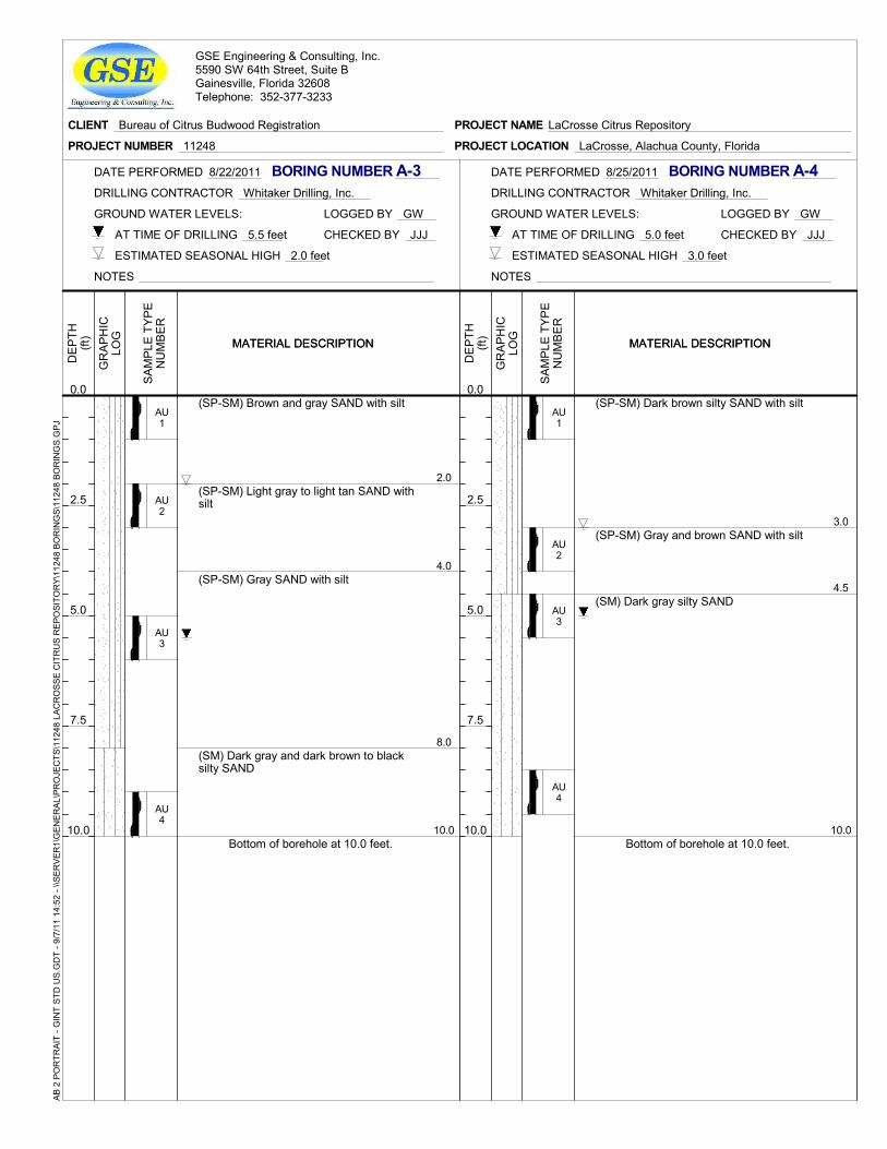
2.0
4.0
8.0
10.0
(SP-SM) Brown and gray SAND with silt
(SP-SM) Light gray to light tan SAND withsilt
(SP-SM) Gray SAND with silt
(SM) Dark gray and dark brown to blacksilty SAND
Bottom of borehole at 10.0 feet.
AU1
AU2
AU3
AU4
GR
AP
HIC
LOG
DE
PTH
(ft)
0.0
2.5
5.0
7.5
10.0
MATERIAL DESCRIPTIONMATERIAL DESCRIPTION
SA
MP
LE T
YP
EN
UM
BE
R
GROUND WATER LEVELS:
CHECKED BY JJJ
LOGGED BY GW
NOTES
AT TIME OF DRILLING 5.5 feet
DRILLING CONTRACTOR Whitaker Drilling, Inc.
BORING NUMBER A-3
ESTIMATED SEASONAL HIGH 2.0 feet
DATE PERFORMED 8/22/2011
CLIENT Bureau of Citrus Budwood Registration
PROJECT NUMBER 11248 PROJECT LOCATION LaCrosse, Alachua County, Florida
PROJECT NAME LaCrosse Citrus Repository
GSE Engineering & Consulting, Inc.5590 SW 64th Street, Suite BGainesville, Florida 32608Telephone: 352-377-3233
AB 2
PO
RTR
AIT
- GIN
T ST
D U
S.G
DT
- 9/7
/11
14:5
2 - \
\SER
VER
1\G
ENER
AL\P
RO
JEC
TS\1
1248
LAC
RO
SSE
CIT
RU
S R
EPO
SITO
RY\
1124
8 BO
RIN
GS\
1124
8 BO
RIN
GS.
GPJ
3.0
4.5
10.0
(SP-SM) Dark brown silty SAND with silt
(SP-SM) Gray and brown SAND with silt
(SM) Dark gray silty SAND
Bottom of borehole at 10.0 feet.
AU1
AU2
AU3
AU4
GR
AP
HIC
LOG
DE
PTH
(ft)
0.0
2.5
5.0
7.5
10.0
MATERIAL DESCRIPTIONMATERIAL DESCRIPTION
SA
MP
LE T
YP
EN
UM
BE
R
GROUND WATER LEVELS:
CHECKED BY JJJ
LOGGED BY GW
NOTES
AT TIME OF DRILLING 5.0 feet
DRILLING CONTRACTOR Whitaker Drilling, Inc.
BORING NUMBER A-4
ESTIMATED SEASONAL HIGH 3.0 feet
DATE PERFORMED 8/25/2011
3.0
5.0
(SP-SM) Brown and gray SAND with silt
(SP-SM) Light gray to light tan SAND withsilt
Bottom of borehole at 5.0 feet.
AU1
AU2
GR
AP
HIC
LOG
DE
PTH
(ft)
0.0
2.5
5.0
MATERIAL DESCRIPTIONMATERIAL DESCRIPTION
SA
MP
LE T
YP
EN
UM
BE
R
GROUND WATER LEVELS:
CHECKED BY JJJ
LOGGED BY GW
NOTES
AT TIME OF DRILLING NE
DRILLING CONTRACTOR Whitaker Drilling, Inc.
BORING NUMBER R-1
ESTIMATED SEASONAL HIGH 3.0 feet
DATE PERFORMED 8/22/2011
(Continued Next Page)
CLIENT Bureau of Citrus Budwood Registration
PROJECT NUMBER 11248 PROJECT LOCATION LaCrosse, Alachua County, Florida
PROJECT NAME LaCrosse Citrus Repository
GSE Engineering & Consulting, Inc.5590 SW 64th Street, Suite BGainesville, Florida 32608Telephone: 352-377-3233
AB 2
PO
RTR
AIT
- GIN
T ST
D U
S.G
DT
- 9/7
/11
14:5
3 - \
\SER
VER
1\G
ENER
AL\P
RO
JEC
TS\1
1248
LAC
RO
SSE
CIT
RU
S R
EPO
SITO
RY\
1124
8 BO
RIN
GS\
1124
8 BO
RIN
GS.
GPJ
2.0
4.0
5.0
(SP-SM) Gray SAND with silt
(SP-SM) Light gray SAND with silt
(SP-SM) Light gray to light brown SANDwith silt
Bottom of borehole at 5.0 feet.
AU1
AU2
AU3
GR
AP
HIC
LOG
DE
PTH
(ft)
0.0
2.5
5.0
MATERIAL DESCRIPTIONMATERIAL DESCRIPTION
SA
MP
LE T
YP
EN
UM
BE
R
GROUND WATER LEVELS:
CHECKED BY JJJ
LOGGED BY GW
NOTES
AT TIME OF DRILLING NE
DRILLING CONTRACTOR Whitaker Drilling, Inc.
BORING NUMBER R-2
ESTIMATED SEASONAL HIGH 2.0 feet
DATE PERFORMED 8/22/2011
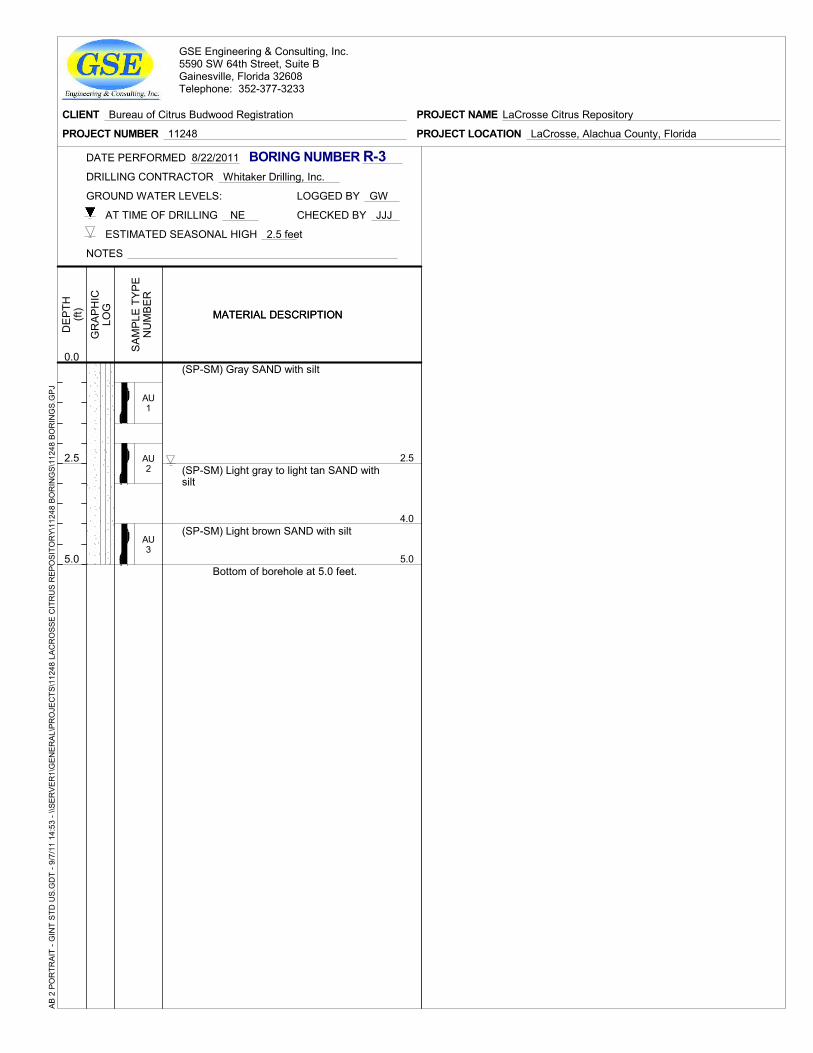
2.5
4.0
5.0
(SP-SM) Gray SAND with silt
(SP-SM) Light gray to light tan SAND withsilt
(SP-SM) Light brown SAND with silt
Bottom of borehole at 5.0 feet.
AU1
AU2
AU3
GR
AP
HIC
LOG
DE
PTH
(ft)
0.0
2.5
5.0
MATERIAL DESCRIPTIONMATERIAL DESCRIPTION
SA
MP
LE T
YP
EN
UM
BE
R
GROUND WATER LEVELS:
CHECKED BY JJJ
LOGGED BY GW
NOTES
AT TIME OF DRILLING NE
DRILLING CONTRACTOR Whitaker Drilling, Inc.
BORING NUMBER R-3
ESTIMATED SEASONAL HIGH 2.5 feet
DATE PERFORMED 8/22/2011
CLIENT Bureau of Citrus Budwood Registration
PROJECT NUMBER 11248 PROJECT LOCATION LaCrosse, Alachua County, Florida
PROJECT NAME LaCrosse Citrus Repository
GSE Engineering & Consulting, Inc.5590 SW 64th Street, Suite BGainesville, Florida 32608Telephone: 352-377-3233
AB 2
PO
RTR
AIT
- GIN
T ST
D U
S.G
DT
- 9/7
/11
14:5
3 - \
\SER
VER
1\G
ENER
AL\P
RO
JEC
TS\1
1248
LAC
RO
SSE
CIT
RU
S R
EPO
SITO
RY\
1124
8 BO
RIN
GS\
1124
8 BO
RIN
GS.
GPJ
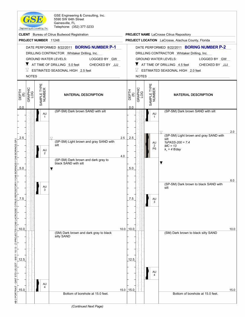
2.5
4.0
10.0
15.0
(SP-SM) Dark brown SAND with silt
(SP-SM) Light brown and gray SAND withsilt
(SP-SM) Dark brown and dark gray toblack SAND with silt
(SM) Dark brown and dark gray to blacksilty SAND
Bottom of borehole at 15.0 feet.
AU1
AU2
AU3
AU4
GR
AP
HIC
LOG
DE
PTH
(ft)
0.0
2.5
5.0
7.5
10.0
12.5
15.0
MATERIAL DESCRIPTIONMATERIAL DESCRIPTION
SA
MP
LE T
YP
EN
UM
BE
R
GROUND WATER LEVELS:
CHECKED BY JJJ
LOGGED BY GW
NOTES
AT TIME OF DRILLING 5.0 feet
DRILLING CONTRACTOR Whitaker Drilling, Inc.
BORING NUMBER P-1
ESTIMATED SEASONAL HIGH 2.5 feet
DATE PERFORMED 8/22/2011
(Continued Next Page)
CLIENT Bureau of Citrus Budwood Registration
PROJECT NUMBER 11248 PROJECT LOCATION LaCrosse, Alachua County, Florida
PROJECT NAME LaCrosse Citrus Repository
GSE Engineering & Consulting, Inc.5590 SW 64th StreetGainesville, FLTelephone: (352) 377-3233
AB 2
PO
RTR
AIT
- GIN
T ST
D U
S.G
DT
- 9/8
/11
10:1
3 - Z
:\PR
OJE
CTS
\112
48 L
ACR
OSS
E C
ITR
US
REP
OSI
TOR
Y\11
248
BOR
ING
S\11
248
BOR
ING
S.G
PJ
2.0
6.0
10.0
15.0
(SP-SM) Dark brown SAND with silt
(SP-SM) Light brown and gray SAND withsilt%PASS-200 = 7.4MC = 13kv = 4 ft/day
(SP-SM) Dark brown to black SAND withsilt
(SM) Dark brown to black silty SAND
Bottom of borehole at 15.0 feet.
AU1
AU2
PS
AU3
AU4
GR
AP
HIC
LOG
DE
PTH
(ft)
0.0
2.5
5.0
7.5
10.0
12.5
15.0
MATERIAL DESCRIPTIONMATERIAL DESCRIPTION
SA
MP
LE T
YP
EN
UM
BE
R
GROUND WATER LEVELS:
CHECKED BY JJJ
LOGGED BY GW
NOTES
AT TIME OF DRILLING 4.5 feet
DRILLING CONTRACTOR Whitaker Drilling, Inc.
BORING NUMBER P-2
ESTIMATED SEASONAL HIGH 2.0 feet
DATE PERFORMED 8/22/2011
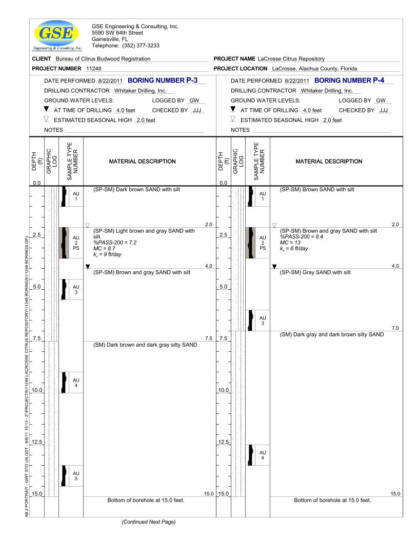
2.0
4.0
7.5
15.0
(SP-SM) Dark brown SAND with silt
(SP-SM) Light brown and gray SAND withsilt%PASS-200 = 7.2MC = 8.7kv = 9 ft/day
(SP-SM) Brown and gray SAND with silt
(SM) Dark brown and dark gray silty SAND
Bottom of borehole at 15.0 feet.
AU1
AU2
PS
AU3
AU4
AU5
GR
AP
HIC
LOG
DE
PTH
(ft)
0.0
2.5
5.0
7.5
10.0
12.5
15.0
MATERIAL DESCRIPTIONMATERIAL DESCRIPTION
SA
MP
LE T
YP
EN
UM
BE
R
GROUND WATER LEVELS:
CHECKED BY JJJ
LOGGED BY GW
NOTES
AT TIME OF DRILLING 4.0 feet
DRILLING CONTRACTOR Whitaker Drilling, Inc.
BORING NUMBER P-3
ESTIMATED SEASONAL HIGH 2.0 feet
DATE PERFORMED 8/22/2011
(Continued Next Page)
CLIENT Bureau of Citrus Budwood Registration
PROJECT NUMBER 11248 PROJECT LOCATION LaCrosse, Alachua County, Florida
PROJECT NAME LaCrosse Citrus Repository
GSE Engineering & Consulting, Inc.5590 SW 64th StreetGainesville, FLTelephone: (352) 377-3233
AB 2
PO
RTR
AIT
- GIN
T ST
D U
S.G
DT
- 9/8
/11
10:1
3 - Z
:\PR
OJE
CTS
\112
48 L
ACR
OSS
E C
ITR
US
REP
OSI
TOR
Y\11
248
BOR
ING
S\11
248
BOR
ING
S.G
PJ
2.0
4.0
7.0
15.0
(SP-SM) Brown SAND with silt
(SP-SM) Brown and gray SAND with silt%PASS-200 = 8.4MC = 13kv = 6 ft/day
(SP-SM) Gray SAND with silt
(SM) Dark gray and dark brown silty SAND
Bottom of borehole at 15.0 feet.
AU1
AU2
PS
AU3
AU4
GR
AP
HIC
LOG
DE
PTH
(ft)
0.0
2.5
5.0
7.5
10.0
12.5
15.0
MATERIAL DESCRIPTIONMATERIAL DESCRIPTION
SA
MP
LE T
YP
EN
UM
BE
R
GROUND WATER LEVELS:
CHECKED BY JJJ
LOGGED BY GW
NOTES
AT TIME OF DRILLING 4.0 feet
DRILLING CONTRACTOR Whitaker Drilling, Inc.
BORING NUMBER P-4
ESTIMATED SEASONAL HIGH 2.0 feet
DATE PERFORMED 8/22/2011
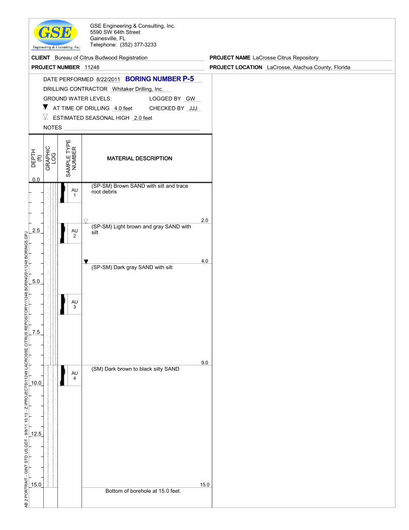
2.0
4.0
9.0
15.0
(SP-SM) Brown SAND with silt and traceroot debris
(SP-SM) Light brown and gray SAND withsilt
(SP-SM) Dark gray SAND with silt
(SM) Dark brown to black silty SAND
Bottom of borehole at 15.0 feet.
AU1
AU2
AU3
AU4
GR
AP
HIC
LOG
DE
PTH
(ft)
0.0
2.5
5.0
7.5
10.0
12.5
15.0
MATERIAL DESCRIPTIONMATERIAL DESCRIPTION
SA
MP
LE T
YP
EN
UM
BE
R
GROUND WATER LEVELS:
CHECKED BY JJJ
LOGGED BY GW
NOTES
AT TIME OF DRILLING 4.0 feet
DRILLING CONTRACTOR Whitaker Drilling, Inc.
BORING NUMBER P-5
ESTIMATED SEASONAL HIGH 2.0 feet
DATE PERFORMED 8/22/2011
CLIENT Bureau of Citrus Budwood Registration
PROJECT NUMBER 11248 PROJECT LOCATION LaCrosse, Alachua County, Florida
PROJECT NAME LaCrosse Citrus Repository
GSE Engineering & Consulting, Inc.5590 SW 64th StreetGainesville, FLTelephone: (352) 377-3233
AB 2
PO
RTR
AIT
- GIN
T ST
D U
S.G
DT
- 9/8
/11
10:1
3 - Z
:\PR
OJE
CTS
\112
48 L
ACR
OSS
E C
ITR
US
REP
OSI
TOR
Y\11
248
BOR
ING
S\11
248
BOR
ING
S.G
PJ

Summary Report of a Geotechnical Site Exploration September 8, 2011 LaCrosse Citrus Repository LaCrosse, Alachua County, Florida GSE Project No. 11248
5-3
5.2 Standard Penetration Test Soil Boring Logs
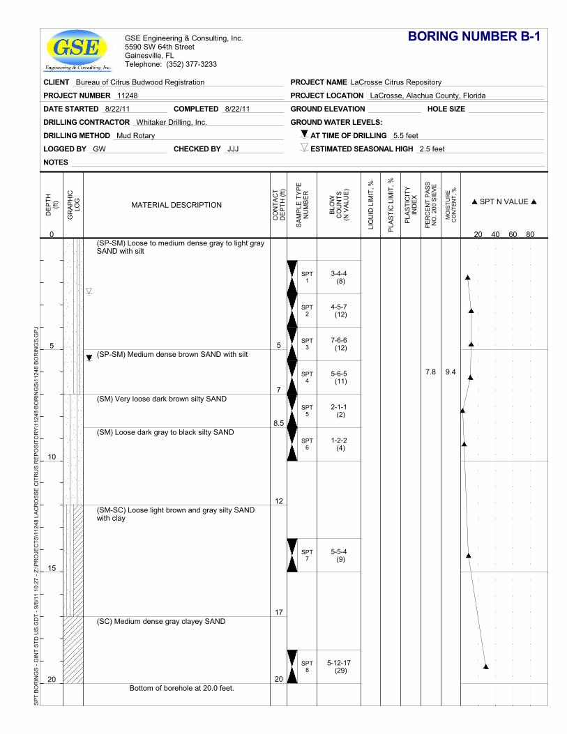
7.8 9.4
5
7
8.5
12
17
20
SPT1
SPT2
SPT3
SPT4
SPT5
SPT6
SPT7
SPT8
(SP-SM) Loose to medium dense gray to light graySAND with silt
(SP-SM) Medium dense brown SAND with silt
(SM) Very loose dark brown silty SAND
(SM) Loose dark gray to black silty SAND
(SM-SC) Loose light brown and gray silty SANDwith clay
(SC) Medium dense gray clayey SAND
Bottom of borehole at 20.0 feet.
3-4-4 (8)
4-5-7 (12)
7-6-6 (12)
5-6-5 (11)
2-1-1 (2)
1-2-2 (4)
5-5-4 (9)
5-12-17 (29)
GROUND ELEVATION
LOGGED BY GW
DRILLING METHOD Mud Rotary
HOLE SIZE
DRILLING CONTRACTOR Whitaker Drilling, Inc. GROUND WATER LEVELS:
CHECKED BY JJJ
DATE STARTED 8/22/11 COMPLETED 8/22/11
AT TIME OF DRILLING 5.5 feet
ESTIMATED SEASONAL HIGH 2.5 feet
NOTES
GR
AP
HIC
LOG
PER
CEN
T PA
SSN
O. 2
00 S
IEVE
MO
ISTU
RE
CO
NTE
NT,
%
DE
PTH
(ft)
0
5
10
15
20
CO
NTA
CT
DE
PTH
(ft)
PLA
STI
CIT
YIN
DE
X
LIQ
UID
LIM
IT, %
PLA
STI
C L
IMIT
, %
SA
MP
LE T
YP
EN
UM
BE
R
MATERIAL DESCRIPTION
BLO
WC
OU
NTS
(N V
ALU
E)
SPT N VALUE
20 40 60 80
BORING NUMBER B-1
CLIENT Bureau of Citrus Budwood Registration
PROJECT NUMBER 11248 PROJECT LOCATION LaCrosse, Alachua County, Florida
PROJECT NAME LaCrosse Citrus Repository
GSE Engineering & Consulting, Inc.5590 SW 64th StreetGainesville, FLTelephone: (352) 377-3233
SPT
BOR
ING
S - G
INT
STD
US.
GD
T - 9
/8/1
1 10
:27
- Z:\P
RO
JEC
TS\1
1248
LAC
RO
SSE
CIT
RU
S R
EPO
SITO
RY\
1124
8 BO
RIN
GS\
1124
8 BO
RIN
GS.
GPJ
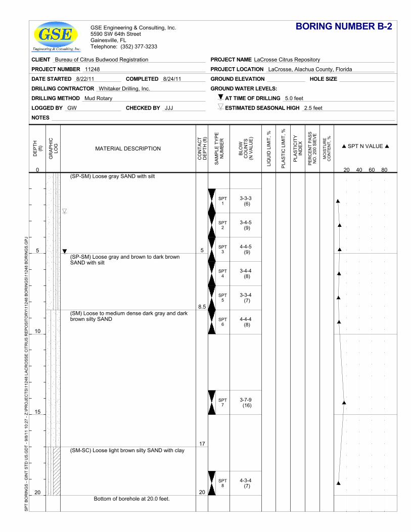
5
8.5
17
20
SPT1
SPT2
SPT3
SPT4
SPT5
SPT6
SPT7
SPT8
(SP-SM) Loose gray SAND with silt
(SP-SM) Loose gray and brown to dark brownSAND with silt
(SM) Loose to medium dense dark gray and darkbrown silty SAND
(SM-SC) Loose light brown silty SAND with clay
Bottom of borehole at 20.0 feet.
3-3-3 (6)
3-4-5 (9)
4-4-5 (9)
3-4-4 (8)
3-3-4 (7)
4-4-4 (8)
3-7-9 (16)
4-3-4 (7)
GROUND ELEVATION
LOGGED BY GW
DRILLING METHOD Mud Rotary
HOLE SIZE
DRILLING CONTRACTOR Whitaker Drilling, Inc. GROUND WATER LEVELS:
CHECKED BY JJJ
DATE STARTED 8/22/11 COMPLETED 8/24/11
AT TIME OF DRILLING 5.0 feet
ESTIMATED SEASONAL HIGH 2.5 feet
NOTES
GR
AP
HIC
LOG
PER
CEN
T PA
SSN
O. 2
00 S
IEVE
MO
ISTU
RE
CO
NTE
NT,
%
DE
PTH
(ft)
0
5
10
15
20
CO
NTA
CT
DE
PTH
(ft)
PLA
STI
CIT
YIN
DE
X
LIQ
UID
LIM
IT, %
PLA
STI
C L
IMIT
, %
SA
MP
LE T
YP
EN
UM
BE
R
MATERIAL DESCRIPTION
BLO
WC
OU
NTS
(N V
ALU
E)
SPT N VALUE
20 40 60 80
BORING NUMBER B-2
CLIENT Bureau of Citrus Budwood Registration
PROJECT NUMBER 11248 PROJECT LOCATION LaCrosse, Alachua County, Florida
PROJECT NAME LaCrosse Citrus Repository
GSE Engineering & Consulting, Inc.5590 SW 64th StreetGainesville, FLTelephone: (352) 377-3233
SPT
BOR
ING
S - G
INT
STD
US.
GD
T - 9
/8/1
1 10
:27
- Z:\P
RO
JEC
TS\1
1248
LAC
RO
SSE
CIT
RU
S R
EPO
SITO
RY\
1124
8 BO
RIN
GS\
1124
8 BO
RIN
GS.
GPJ
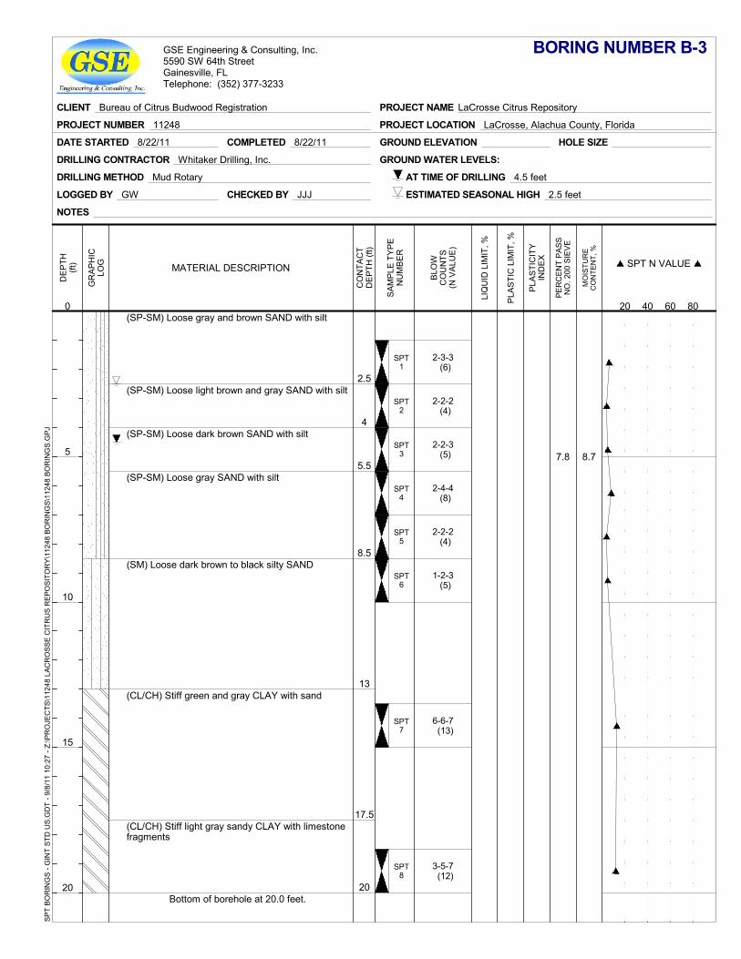
7.8 8.7
2.5
4
5.5
8.5
13
17.5
20
SPT1
SPT2
SPT3
SPT4
SPT5
SPT6
SPT7
SPT8
(SP-SM) Loose gray and brown SAND with silt
(SP-SM) Loose light brown and gray SAND with silt
(SP-SM) Loose dark brown SAND with silt
(SP-SM) Loose gray SAND with silt
(SM) Loose dark brown to black silty SAND
(CL/CH) Stiff green and gray CLAY with sand
(CL/CH) Stiff light gray sandy CLAY with limestonefragments
Bottom of borehole at 20.0 feet.
2-3-3 (6)
2-2-2 (4)
2-2-3 (5)
2-4-4 (8)
2-2-2 (4)
1-2-3 (5)
6-6-7 (13)
3-5-7 (12)
GROUND ELEVATION
LOGGED BY GW
DRILLING METHOD Mud Rotary
HOLE SIZE
DRILLING CONTRACTOR Whitaker Drilling, Inc. GROUND WATER LEVELS:
CHECKED BY JJJ
DATE STARTED 8/22/11 COMPLETED 8/22/11
AT TIME OF DRILLING 4.5 feet
ESTIMATED SEASONAL HIGH 2.5 feet
NOTES
GR
AP
HIC
LOG
PER
CEN
T PA
SSN
O. 2
00 S
IEVE
MO
ISTU
RE
CO
NTE
NT,
%
DE
PTH
(ft)
0
5
10
15
20
CO
NTA
CT
DE
PTH
(ft)
PLA
STI
CIT
YIN
DE
X
LIQ
UID
LIM
IT, %
PLA
STI
C L
IMIT
, %
SA
MP
LE T
YP
EN
UM
BE
R
MATERIAL DESCRIPTION
BLO
WC
OU
NTS
(N V
ALU
E)
SPT N VALUE
20 40 60 80
BORING NUMBER B-3
CLIENT Bureau of Citrus Budwood Registration
PROJECT NUMBER 11248 PROJECT LOCATION LaCrosse, Alachua County, Florida
PROJECT NAME LaCrosse Citrus Repository
GSE Engineering & Consulting, Inc.5590 SW 64th StreetGainesville, FLTelephone: (352) 377-3233
SPT
BOR
ING
S - G
INT
STD
US.
GD
T - 9
/8/1
1 10
:27
- Z:\P
RO
JEC
TS\1
1248
LAC
RO
SSE
CIT
RU
S R
EPO
SITO
RY\
1124
8 BO
RIN
GS\
1124
8 BO
RIN
GS.
GPJ

2.5
6
8.5
11
17
20
SPT1
SPT2
SPT3
SPT4
SPT5
SPT6
SPT7
SPT8
(SP-SM) Medium dense gray and brown SANDwith silt
(SP-SM) Medium dense gray and light brownSAND with silt
(SP-SM) Medium dense brown SAND with silt
(SP-SM) Loose brown and gray SAND with silt
(SM) Medium dense dark gray to black silty SAND
(CL/CH) Very stiff gray to pale green CLAY withlenses of sand
Bottom of borehole at 20.0 feet.
5-6-6 (12)
6-7-7 (14)
7-9-14 (23)
14-15-12 (27)
7-7-5 (12)
3-3-4 (7)
4-5-7 (12)
8-9-11 (20)
GROUND ELEVATION
LOGGED BY GW
DRILLING METHOD Mud Rotary
HOLE SIZE
DRILLING CONTRACTOR Whitaker Drilling, Inc. GROUND WATER LEVELS:
CHECKED BY JJJ
DATE STARTED 8/25/11 COMPLETED 8/25/11
AT TIME OF DRILLING 5.0 feet
ESTIMATED SEASONAL HIGH 2.5 feet
NOTES
GR
AP
HIC
LOG
PER
CEN
T PA
SSN
O. 2
00 S
IEVE
MO
ISTU
RE
CO
NTE
NT,
%
DE
PTH
(ft)
0
5
10
15
20
CO
NTA
CT
DE
PTH
(ft)
PLA
STI
CIT
YIN
DE
X
LIQ
UID
LIM
IT, %
PLA
STI
C L
IMIT
, %
SA
MP
LE T
YP
EN
UM
BE
R
MATERIAL DESCRIPTION
BLO
WC
OU
NTS
(N V
ALU
E)
SPT N VALUE
20 40 60 80
BORING NUMBER B-4
CLIENT Bureau of Citrus Budwood Registration
PROJECT NUMBER 11248 PROJECT LOCATION LaCrosse, Alachua County, Florida
PROJECT NAME LaCrosse Citrus Repository
GSE Engineering & Consulting, Inc.5590 SW 64th StreetGainesville, FLTelephone: (352) 377-3233
SPT
BOR
ING
S - G
INT
STD
US.
GD
T - 9
/8/1
1 10
:27
- Z:\P
RO
JEC
TS\1
1248
LAC
RO
SSE
CIT
RU
S R
EPO
SITO
RY\
1124
8 BO
RIN
GS\
1124
8 BO
RIN
GS.
GPJ
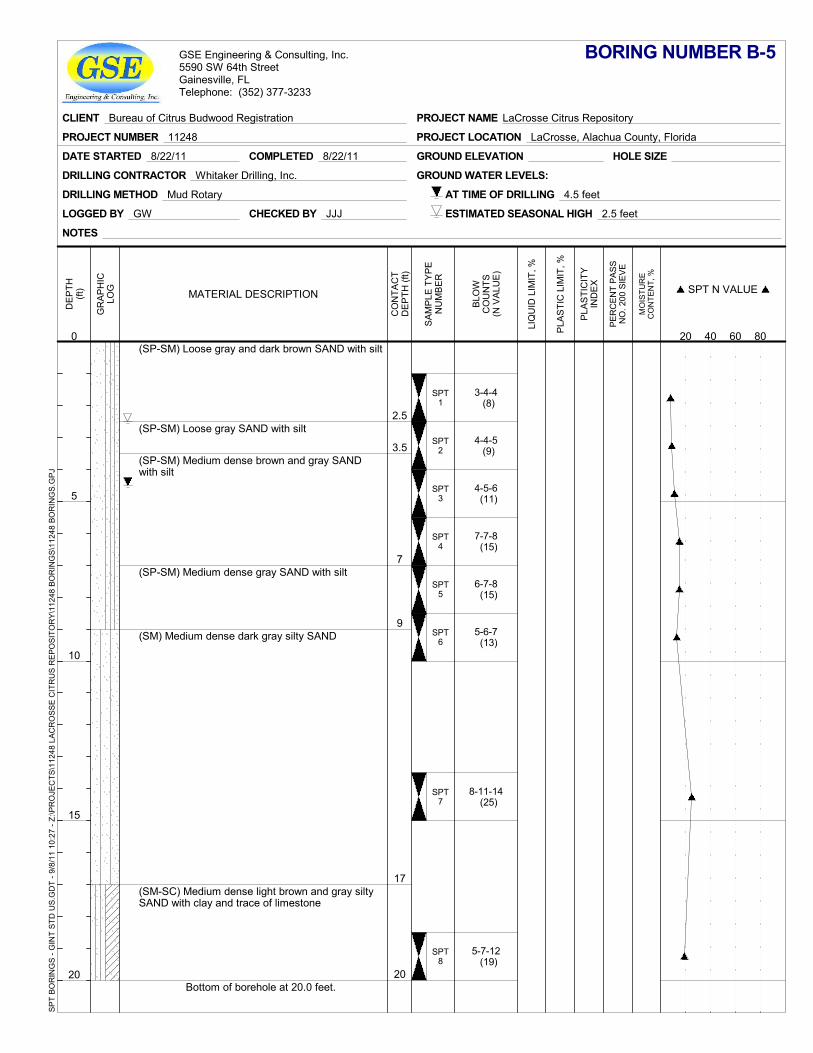
2.5
3.5
7
9
17
20
SPT1
SPT2
SPT3
SPT4
SPT5
SPT6
SPT7
SPT8
(SP-SM) Loose gray and dark brown SAND with silt
(SP-SM) Loose gray SAND with silt
(SP-SM) Medium dense brown and gray SANDwith silt
(SP-SM) Medium dense gray SAND with silt
(SM) Medium dense dark gray silty SAND
(SM-SC) Medium dense light brown and gray siltySAND with clay and trace of limestone
Bottom of borehole at 20.0 feet.
3-4-4 (8)
4-4-5 (9)
4-5-6 (11)
7-7-8 (15)
6-7-8 (15)
5-6-7 (13)
8-11-14 (25)
5-7-12 (19)
GROUND ELEVATION
LOGGED BY GW
DRILLING METHOD Mud Rotary
HOLE SIZE
DRILLING CONTRACTOR Whitaker Drilling, Inc. GROUND WATER LEVELS:
CHECKED BY JJJ
DATE STARTED 8/22/11 COMPLETED 8/22/11
AT TIME OF DRILLING 4.5 feet
ESTIMATED SEASONAL HIGH 2.5 feet
NOTES
GR
AP
HIC
LOG
PER
CEN
T PA
SSN
O. 2
00 S
IEVE
MO
ISTU
RE
CO
NTE
NT,
%
DE
PTH
(ft)
0
5
10
15
20
CO
NTA
CT
DE
PTH
(ft)
PLA
STI
CIT
YIN
DE
X
LIQ
UID
LIM
IT, %
PLA
STI
C L
IMIT
, %
SA
MP
LE T
YP
EN
UM
BE
R
MATERIAL DESCRIPTION
BLO
WC
OU
NTS
(N V
ALU
E)
SPT N VALUE
20 40 60 80
BORING NUMBER B-5
CLIENT Bureau of Citrus Budwood Registration
PROJECT NUMBER 11248 PROJECT LOCATION LaCrosse, Alachua County, Florida
PROJECT NAME LaCrosse Citrus Repository
GSE Engineering & Consulting, Inc.5590 SW 64th StreetGainesville, FLTelephone: (352) 377-3233
SPT
BOR
ING
S - G
INT
STD
US.
GD
T - 9
/8/1
1 10
:27
- Z:\P
RO
JEC
TS\1
1248
LAC
RO
SSE
CIT
RU
S R
EPO
SITO
RY\
1124
8 BO
RIN
GS\
1124
8 BO
RIN
GS.
GPJ
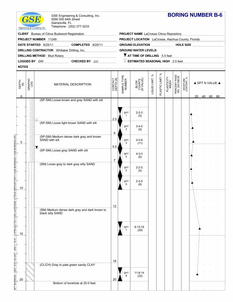
2.5
4
5.5
7
12
18
20
SPT1
SPT2
SPT3
SPT4
SPT5
SPT6
SPT7
SPT8
(SP-SM) Loose brown and gray SAND with silt
(SP-SM) Loose light brown SAND with silt
(SP-SM) Medium dense dark gray and brownSAND with silt
(SP-SM) Loose gray SAND with silt
(SM) Loose gray to dark gray silty SAND
(SM) Medium dense dark gray and dark brown toblack silty SAND
(CL/CH) Gray to pale green sandy CLAY
Bottom of borehole at 20.0 feet.
2-2-3 (5)
3-4-5 (9)
4-5-6 (11)
4-3-3 (6)
2-2-3 (5)
2-3-5 (8)
9-13-16 (29)
11-8-14 (22)
GROUND ELEVATION
LOGGED BY GW
DRILLING METHOD Mud Rotary
HOLE SIZE
DRILLING CONTRACTOR Whitaker Drilling, Inc. GROUND WATER LEVELS:
CHECKED BY JJJ
DATE STARTED 8/25/11 COMPLETED 8/25/11
AT TIME OF DRILLING 5.5 feet
ESTIMATED SEASONAL HIGH 2.5 feet
NOTES
GR
AP
HIC
LOG
PER
CEN
T PA
SSN
O. 2
00 S
IEVE
MO
ISTU
RE
CO
NTE
NT,
%
DE
PTH
(ft)
0
5
10
15
20
CO
NTA
CT
DE
PTH
(ft)
PLA
STI
CIT
YIN
DE
X
LIQ
UID
LIM
IT, %
PLA
STI
C L
IMIT
, %
SA
MP
LE T
YP
EN
UM
BE
R
MATERIAL DESCRIPTION
BLO
WC
OU
NTS
(N V
ALU
E)
SPT N VALUE
20 40 60 80
BORING NUMBER B-6
CLIENT Bureau of Citrus Budwood Registration
PROJECT NUMBER 11248 PROJECT LOCATION LaCrosse, Alachua County, Florida
PROJECT NAME LaCrosse Citrus Repository
GSE Engineering & Consulting, Inc.5590 SW 64th StreetGainesville, FLTelephone: (352) 377-3233
SPT
BOR
ING
S - G
INT
STD
US.
GD
T - 9
/8/1
1 10
:27
- Z:\P
RO
JEC
TS\1
1248
LAC
RO
SSE
CIT
RU
S R
EPO
SITO
RY\
1124
8 BO
RIN
GS\
1124
8 BO
RIN
GS.
GPJ
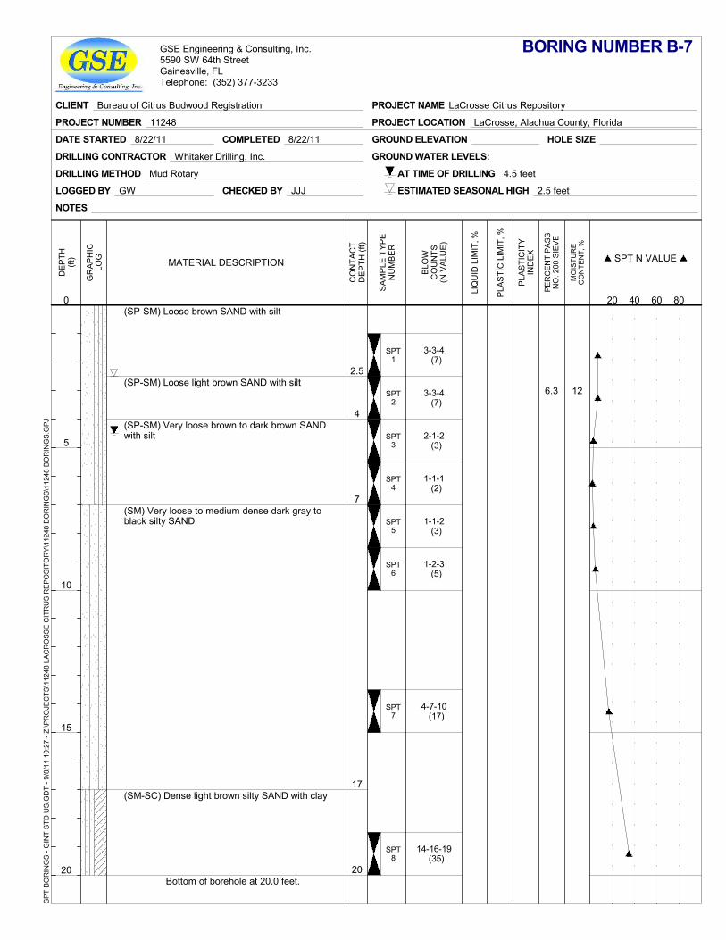
6.3 12
2.5
4
7
17
20
SPT1
SPT2
SPT3
SPT4
SPT5
SPT6
SPT7
SPT8
(SP-SM) Loose brown SAND with silt
(SP-SM) Loose light brown SAND with silt
(SP-SM) Very loose brown to dark brown SANDwith silt
(SM) Very loose to medium dense dark gray toblack silty SAND
(SM-SC) Dense light brown silty SAND with clay
Bottom of borehole at 20.0 feet.
3-3-4 (7)
3-3-4 (7)
2-1-2 (3)
1-1-1 (2)
1-1-2 (3)
1-2-3 (5)
4-7-10 (17)
14-16-19 (35)
GROUND ELEVATION
LOGGED BY GW
DRILLING METHOD Mud Rotary
HOLE SIZE
DRILLING CONTRACTOR Whitaker Drilling, Inc. GROUND WATER LEVELS:
CHECKED BY JJJ
DATE STARTED 8/22/11 COMPLETED 8/22/11
AT TIME OF DRILLING 4.5 feet
ESTIMATED SEASONAL HIGH 2.5 feet
NOTES
GR
AP
HIC
LOG
PER
CEN
T PA
SSN
O. 2
00 S
IEVE
MO
ISTU
RE
CO
NTE
NT,
%
DE
PTH
(ft)
0
5
10
15
20
CO
NTA
CT
DE
PTH
(ft)
PLA
STI
CIT
YIN
DE
X
LIQ
UID
LIM
IT, %
PLA
STI
C L
IMIT
, %
SA
MP
LE T
YP
EN
UM
BE
R
MATERIAL DESCRIPTION
BLO
WC
OU
NTS
(N V
ALU
E)
SPT N VALUE
20 40 60 80
BORING NUMBER B-7
CLIENT Bureau of Citrus Budwood Registration
PROJECT NUMBER 11248 PROJECT LOCATION LaCrosse, Alachua County, Florida
PROJECT NAME LaCrosse Citrus Repository
GSE Engineering & Consulting, Inc.5590 SW 64th StreetGainesville, FLTelephone: (352) 377-3233
SPT
BOR
ING
S - G
INT
STD
US.
GD
T - 9
/8/1
1 10
:27
- Z:\P
RO
JEC
TS\1
1248
LAC
RO
SSE
CIT
RU
S R
EPO
SITO
RY\
1124
8 BO
RIN
GS\
1124
8 BO
RIN
GS.
GPJ
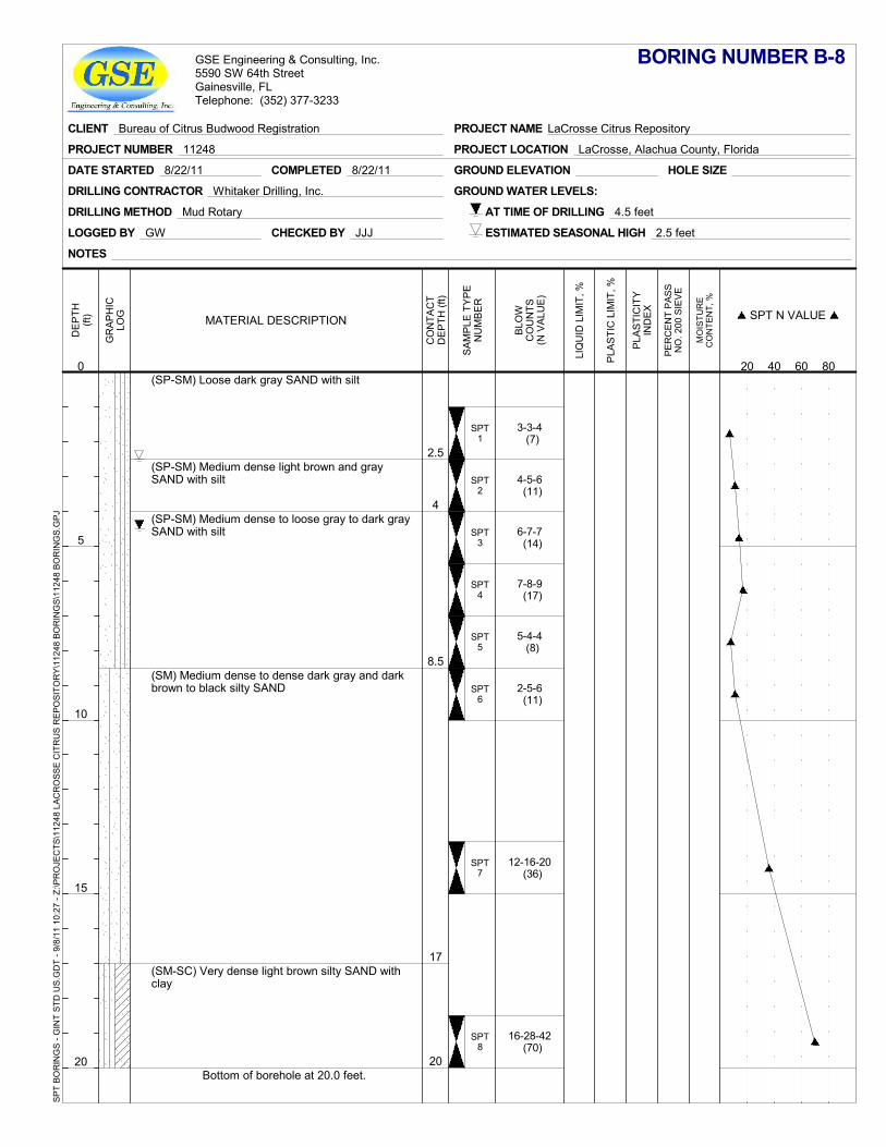
2.5
4
8.5
17
20
SPT1
SPT2
SPT3
SPT4
SPT5
SPT6
SPT7
SPT8
(SP-SM) Loose dark gray SAND with silt
(SP-SM) Medium dense light brown and graySAND with silt
(SP-SM) Medium dense to loose gray to dark graySAND with silt
(SM) Medium dense to dense dark gray and darkbrown to black silty SAND
(SM-SC) Very dense light brown silty SAND withclay
Bottom of borehole at 20.0 feet.
3-3-4 (7)
4-5-6 (11)
6-7-7 (14)
7-8-9 (17)
5-4-4 (8)
2-5-6 (11)
12-16-20 (36)
16-28-42 (70)
GROUND ELEVATION
LOGGED BY GW
DRILLING METHOD Mud Rotary
HOLE SIZE
DRILLING CONTRACTOR Whitaker Drilling, Inc. GROUND WATER LEVELS:
CHECKED BY JJJ
DATE STARTED 8/22/11 COMPLETED 8/22/11
AT TIME OF DRILLING 4.5 feet
ESTIMATED SEASONAL HIGH 2.5 feet
NOTES
GR
AP
HIC
LOG
PER
CEN
T PA
SSN
O. 2
00 S
IEVE
MO
ISTU
RE
CO
NTE
NT,
%
DE
PTH
(ft)
0
5
10
15
20
CO
NTA
CT
DE
PTH
(ft)
PLA
STI
CIT
YIN
DE
X
LIQ
UID
LIM
IT, %
PLA
STI
C L
IMIT
, %
SA
MP
LE T
YP
EN
UM
BE
R
MATERIAL DESCRIPTION
BLO
WC
OU
NTS
(N V
ALU
E)
SPT N VALUE
20 40 60 80
BORING NUMBER B-8
CLIENT Bureau of Citrus Budwood Registration
PROJECT NUMBER 11248 PROJECT LOCATION LaCrosse, Alachua County, Florida
PROJECT NAME LaCrosse Citrus Repository
GSE Engineering & Consulting, Inc.5590 SW 64th StreetGainesville, FLTelephone: (352) 377-3233
SPT
BOR
ING
S - G
INT
STD
US.
GD
T - 9
/8/1
1 10
:27
- Z:\P
RO
JEC
TS\1
1248
LAC
RO
SSE
CIT
RU
S R
EPO
SITO
RY\
1124
8 BO
RIN
GS\
1124
8 BO
RIN
GS.
GPJ
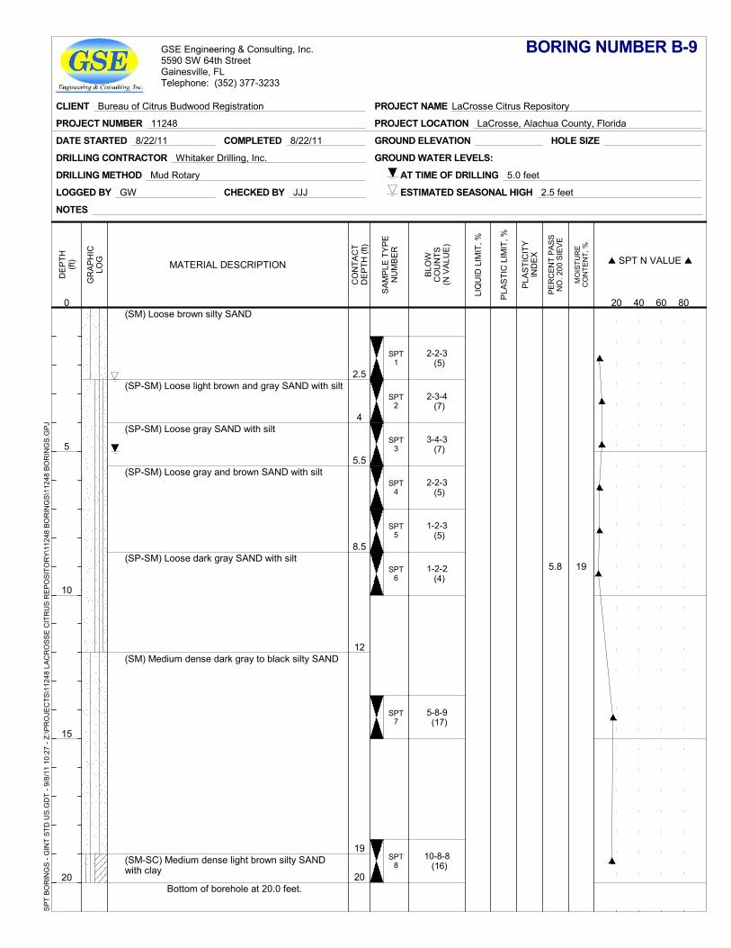
5.8 19
2.5
4
5.5
8.5
12
19
20
SPT1
SPT2
SPT3
SPT4
SPT5
SPT6
SPT7
SPT8
(SM) Loose brown silty SAND
(SP-SM) Loose light brown and gray SAND with silt
(SP-SM) Loose gray SAND with silt
(SP-SM) Loose gray and brown SAND with silt
(SP-SM) Loose dark gray SAND with silt
(SM) Medium dense dark gray to black silty SAND
(SM-SC) Medium dense light brown silty SANDwith clay
Bottom of borehole at 20.0 feet.
2-2-3 (5)
2-3-4 (7)
3-4-3 (7)
2-2-3 (5)
1-2-3 (5)
1-2-2 (4)
5-8-9 (17)
10-8-8 (16)
GROUND ELEVATION
LOGGED BY GW
DRILLING METHOD Mud Rotary
HOLE SIZE
DRILLING CONTRACTOR Whitaker Drilling, Inc. GROUND WATER LEVELS:
CHECKED BY JJJ
DATE STARTED 8/22/11 COMPLETED 8/22/11
AT TIME OF DRILLING 5.0 feet
ESTIMATED SEASONAL HIGH 2.5 feet
NOTES
GR
AP
HIC
LOG
PER
CEN
T PA
SSN
O. 2
00 S
IEVE
MO
ISTU
RE
CO
NTE
NT,
%
DE
PTH
(ft)
0
5
10
15
20
CO
NTA
CT
DE
PTH
(ft)
PLA
STI
CIT
YIN
DE
X
LIQ
UID
LIM
IT, %
PLA
STI
C L
IMIT
, %
SA
MP
LE T
YP
EN
UM
BE
R
MATERIAL DESCRIPTION
BLO
WC
OU
NTS
(N V
ALU
E)
SPT N VALUE
20 40 60 80
BORING NUMBER B-9
CLIENT Bureau of Citrus Budwood Registration
PROJECT NUMBER 11248 PROJECT LOCATION LaCrosse, Alachua County, Florida
PROJECT NAME LaCrosse Citrus Repository
GSE Engineering & Consulting, Inc.5590 SW 64th StreetGainesville, FLTelephone: (352) 377-3233
SPT
BOR
ING
S - G
INT
STD
US.
GD
T - 9
/8/1
1 10
:27
- Z:\P
RO
JEC
TS\1
1248
LAC
RO
SSE
CIT
RU
S R
EPO
SITO
RY\
1124
8 BO
RIN
GS\
1124
8 BO
RIN
GS.
GPJ
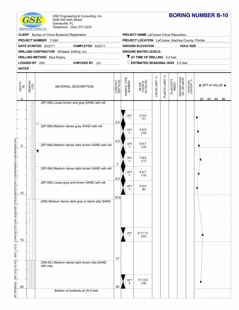
2.5
4.5
7
8.5
10.5
17
20
SPT1
SPT2
SPT3
SPT4
SPT5
SPT6
SPT7
SPT8
(SP-SM) Loose brown and gray SAND with silt
(SP-SM) Medium dense gray SAND with silt
(SP-SM) Medium dense dark brown SAND with silt
(SP-SM) Medium dense dark brown SAND with silt
(SP-SM) Loose gray and brown SAND with silt
(SM) Medium dense dark gray to black silty SAND
(SM-SC) Medium dense light brown silty SANDwith clay
Bottom of borehole at 20.0 feet.
2-3-4 (7)
3-4-6 (10)
5-6-7 (13)
7-8-9 (17)
4-5-7 (12)
3-4-4 (8)
6-11-12 (23)
17-13-5 (18)
GROUND ELEVATION
LOGGED BY GW
DRILLING METHOD Mud Rotary
HOLE SIZE
DRILLING CONTRACTOR Whitaker Drilling, Inc. GROUND WATER LEVELS:
CHECKED BY JJJ
DATE STARTED 8/22/11 COMPLETED 8/22/11
AT TIME OF DRILLING 5.5 feet
ESTIMATED SEASONAL HIGH 2.5 feet
NOTES
GR
AP
HIC
LOG
PER
CEN
T PA
SSN
O. 2
00 S
IEVE
MO
ISTU
RE
CO
NTE
NT,
%
DE
PTH
(ft)
0
5
10
15
20
CO
NTA
CT
DE
PTH
(ft)
PLA
STI
CIT
YIN
DE
X
LIQ
UID
LIM
IT, %
PLA
STI
C L
IMIT
, %
SA
MP
LE T
YP
EN
UM
BE
R
MATERIAL DESCRIPTION
BLO
WC
OU
NTS
(N V
ALU
E)
SPT N VALUE
20 40 60 80
BORING NUMBER B-10
CLIENT Bureau of Citrus Budwood Registration
PROJECT NUMBER 11248 PROJECT LOCATION LaCrosse, Alachua County, Florida
PROJECT NAME LaCrosse Citrus Repository
GSE Engineering & Consulting, Inc.5590 SW 64th StreetGainesville, FLTelephone: (352) 377-3233
SPT
BOR
ING
S - G
INT
STD
US.
GD
T - 9
/8/1
1 10
:27
- Z:\P
RO
JEC
TS\1
1248
LAC
RO
SSE
CIT
RU
S R
EPO
SITO
RY\
1124
8 BO
RIN
GS\
1124
8 BO
RIN
GS.
GPJ
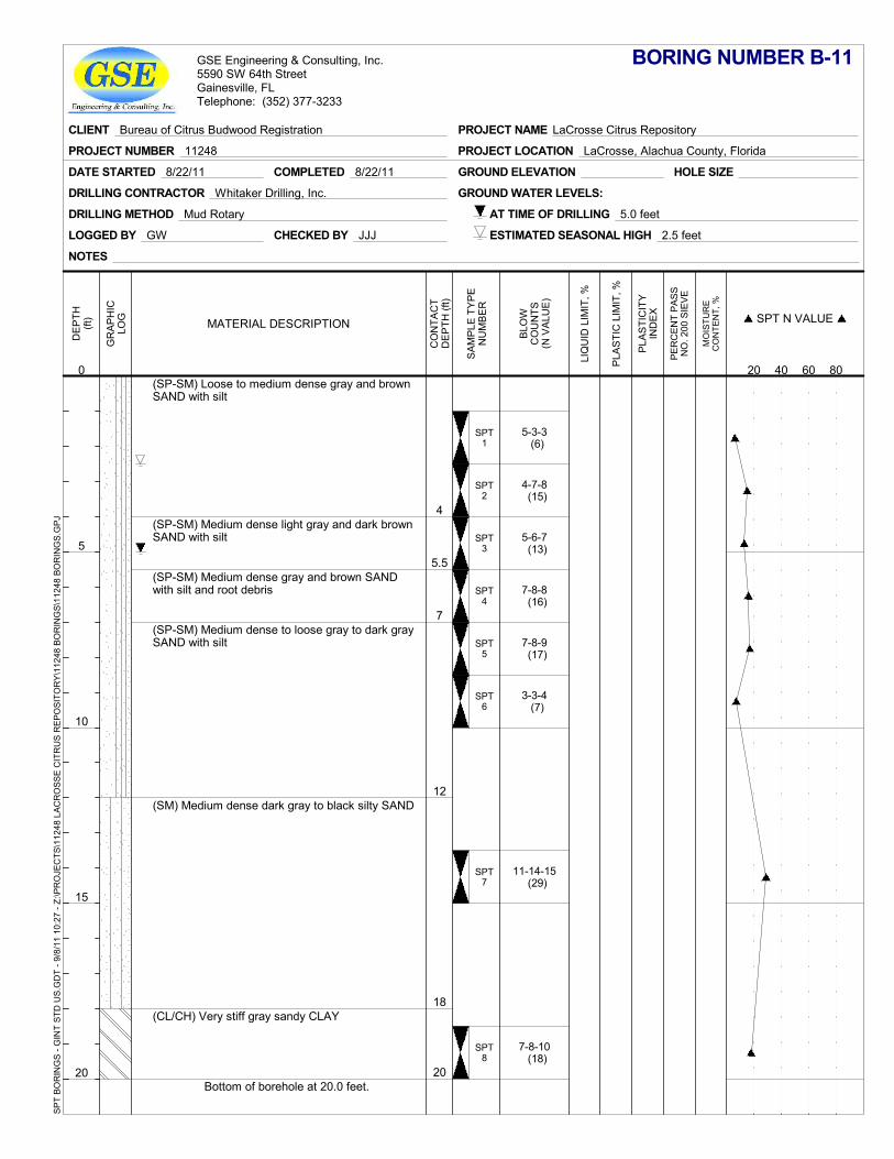
4
5.5
7
12
18
20
SPT1
SPT2
SPT3
SPT4
SPT5
SPT6
SPT7
SPT8
(SP-SM) Loose to medium dense gray and brownSAND with silt
(SP-SM) Medium dense light gray and dark brownSAND with silt
(SP-SM) Medium dense gray and brown SANDwith silt and root debris
(SP-SM) Medium dense to loose gray to dark graySAND with silt
(SM) Medium dense dark gray to black silty SAND
(CL/CH) Very stiff gray sandy CLAY
Bottom of borehole at 20.0 feet.
5-3-3 (6)
4-7-8 (15)
5-6-7 (13)
7-8-8 (16)
7-8-9 (17)
3-3-4 (7)
11-14-15 (29)
7-8-10 (18)
GROUND ELEVATION
LOGGED BY GW
DRILLING METHOD Mud Rotary
HOLE SIZE
DRILLING CONTRACTOR Whitaker Drilling, Inc. GROUND WATER LEVELS:
CHECKED BY JJJ
DATE STARTED 8/22/11 COMPLETED 8/22/11
AT TIME OF DRILLING 5.0 feet
ESTIMATED SEASONAL HIGH 2.5 feet
NOTES
GR
AP
HIC
LOG
PER
CEN
T PA
SSN
O. 2
00 S
IEVE
MO
ISTU
RE
CO
NTE
NT,
%
DE
PTH
(ft)
0
5
10
15
20
CO
NTA
CT
DE
PTH
(ft)
PLA
STI
CIT
YIN
DE
X
LIQ
UID
LIM
IT, %
PLA
STI
C L
IMIT
, %
SA
MP
LE T
YP
EN
UM
BE
R
MATERIAL DESCRIPTION
BLO
WC
OU
NTS
(N V
ALU
E)
SPT N VALUE
20 40 60 80
BORING NUMBER B-11
CLIENT Bureau of Citrus Budwood Registration
PROJECT NUMBER 11248 PROJECT LOCATION LaCrosse, Alachua County, Florida
PROJECT NAME LaCrosse Citrus Repository
GSE Engineering & Consulting, Inc.5590 SW 64th StreetGainesville, FLTelephone: (352) 377-3233
SPT
BOR
ING
S - G
INT
STD
US.
GD
T - 9
/8/1
1 10
:27
- Z:\P
RO
JEC
TS\1
1248
LAC
RO
SSE
CIT
RU
S R
EPO
SITO
RY\
1124
8 BO
RIN
GS\
1124
8 BO
RIN
GS.
GPJ

Summary Report of a Geotechnical Site Exploration September 8, 2011 LaCrosse Citrus Repository LaCrosse, Alachua County, Florida GSE Project No. 11248
5-4
5.3 Laboratory Results
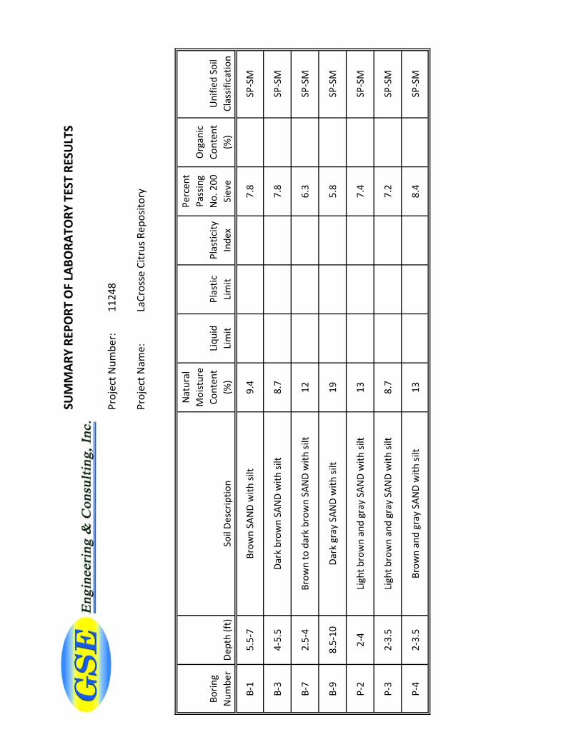
SUM
MAR
Y RE
PORT
OF
LABO
RATO
RY T
EST
RESU
LTS
Proj
ect N
umbe
r:11
248
Proj
ect N
ame:
LaCr
osse
Citr
us R
epos
itory
Borin
g N
umbe
rDe
pth
(ft)
Soil
Desc
riptio
n
Nat
ural
M
oist
ure
Cont
ent
(%)
Liqu
id
Lim
itPl
astic
Li
mit
Plas
ticity
In
dex
Perc
ent
Pass
ing
No.
200
Si
eve
Org
anic
Co
nten
t (%
)U
nifie
d So
il Cl
assif
icat
ion
B-1
5.5-
7Br
own
SAN
D w
ith si
lt9.
47.
8SP
-SM
B-3
4-5.
5Da
rk b
row
n SA
ND
with
silt
8.7
7.8
SP-S
M
B-7
2.5-
4Br
own
to d
ark
brow
n SA
ND
with
silt
126.
3SP
-SM
B-9
8.5-
10Da
rk g
ray
SAN
D w
ith si
lt19
5.8
SP-S
M
P-2
2-4
Ligh
t bro
wn
and
gray
SAN
D w
ith si
lt13
7.4
SP-S
M
P-3
2-3.
5Li
ght b
row
n an
d gr
ay S
AND
with
silt
8.7
7.2
SP-S
M
P-4
2-3.
5Br
own
and
gray
SAN
D w
ith si
lt13
8.4
SP-S
M

Constant Head Permeability Test Results
Project No.: Test Date 8/26/2011Project: LaCrosse Citrus Repository Tested By CFBoring No.:Sample Depth:Soil Description:
Length Between Manometer Outlets 7.62 cmDiameter of Soil Specimen 7.62 cmCross Section Area of Specimen (A) 45.60 cmBottom height of Specimen (h1) 2.5 cmTop height of Specimen (h2) 15.0 cmVolume of Specimen [(h2-h1) * A] 570.00 cm3
Mass of Air Dry Soil 1178.2 gMass of Unused Soil 182.3 gMass of Soil Specimen 995.9 gUnit Weight of Soil Specimen (air dry) 109.02 lb/ft3
Water Content 12.70 percentDry Unit Weight of Soil 96.74 lb/ft3
Trial No. Head Q Time (sec) Temp PermeabilityH1 H2
1 79.1 8.1 71.0 16.63 30.0 1.30E-032 79.1 8.1 71.0 16.45 30.0 1.29E-033 79.1 8.1 71.0 16.58 30.0 1.30E-034 79.1 8.1 71.0 16.49 30.0 1.29E-03
Average Permeability = 1.30E-03 cm/sec
4 ft/day
11248
P-22-4
Light brown and gray SAND with silt
Manometer Readings
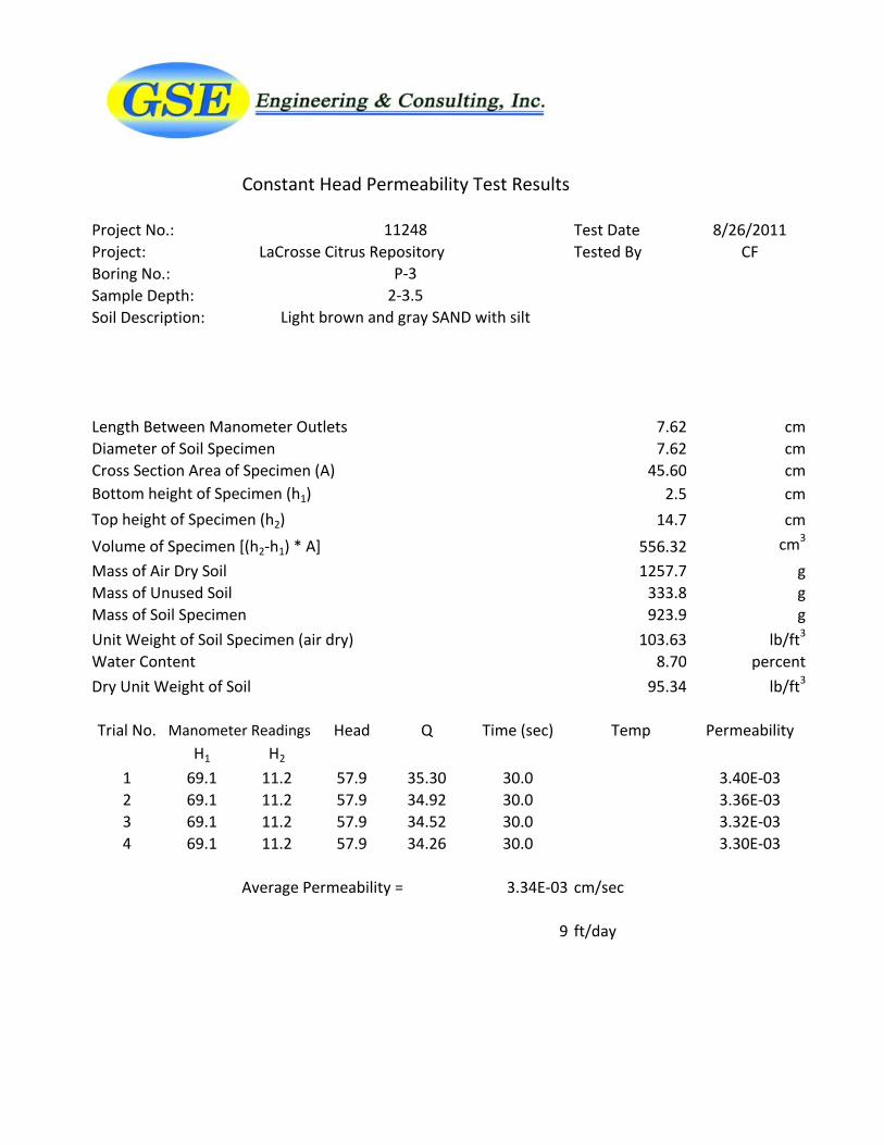
Constant Head Permeability Test Results
Project No.: Test Date 8/26/2011Project: LaCrosse Citrus Repository Tested By CFBoring No.:Sample Depth:Soil Description:
Length Between Manometer Outlets 7.62 cmDiameter of Soil Specimen 7.62 cmCross Section Area of Specimen (A) 45.60 cmBottom height of Specimen (h1) 2.5 cmTop height of Specimen (h2) 14.7 cmVolume of Specimen [(h2-h1) * A] 556.32 cm3
Mass of Air Dry Soil 1257.7 gMass of Unused Soil 333.8 gMass of Soil Specimen 923.9 gUnit Weight of Soil Specimen (air dry) 103.63 lb/ft3
Water Content 8.70 percentDry Unit Weight of Soil 95.34 lb/ft3
Trial No. Head Q Time (sec) Temp PermeabilityH1 H2
1 69.1 11.2 57.9 35.30 30.0 3.40E-032 69.1 11.2 57.9 34.92 30.0 3.36E-033 69.1 11.2 57.9 34.52 30.0 3.32E-034 69.1 11.2 57.9 34.26 30.0 3.30E-03
Average Permeability = 3.34E-03 cm/sec
9 ft/day
11248
P-32-3.5
Light brown and gray SAND with silt
Manometer Readings
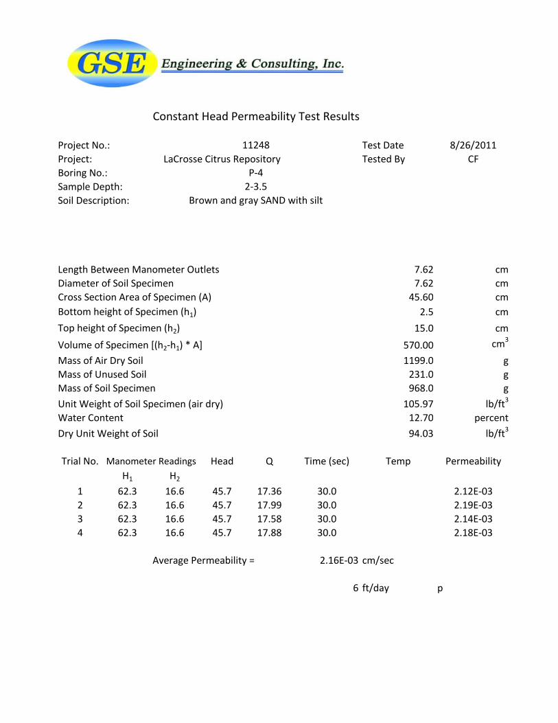
Constant Head Permeability Test Results
Project No.: Test Date 8/26/2011Project: LaCrosse Citrus Repository Tested By CFBoring No.:Sample Depth:Soil Description:
Length Between Manometer Outlets 7.62 cmDiameter of Soil Specimen 7.62 cmCross Section Area of Specimen (A) 45.60 cmBottom height of Specimen (h1) 2.5 cmTop height of Specimen (h2) 15.0 cmVolume of Specimen [(h2-h1) * A] 570.00 cm3
Mass of Air Dry Soil 1199.0 gMass of Unused Soil 231.0 gMass of Soil Specimen 968.0 gUnit Weight of Soil Specimen (air dry) 105.97 lb/ft3
Water Content 12.70 percentDry Unit Weight of Soil 94.03 lb/ft3
Trial No. Head Q Time (sec) Temp PermeabilityH1 H2
1 62.3 16.6 45.7 17.36 30.0 2.12E-032 62.3 16.6 45.7 17.99 30.0 2.19E-033 62.3 16.6 45.7 17.58 30.0 2.14E-034 62.3 16.6 45.7 17.88 30.0 2.18E-03
Average Permeability = 2.16E-03 cm/sec
6 ft/day p
11248
P-42-3.5
Brown and gray SAND with silt
Manometer Readings

Summary Report of a Geotechnical Site Exploration September 8, 2011 LaCrosse Citrus Repository LaCrosse, Alachua County, Florida GSE Project No. 11248
5-5
5.4 Key to Soil Classification
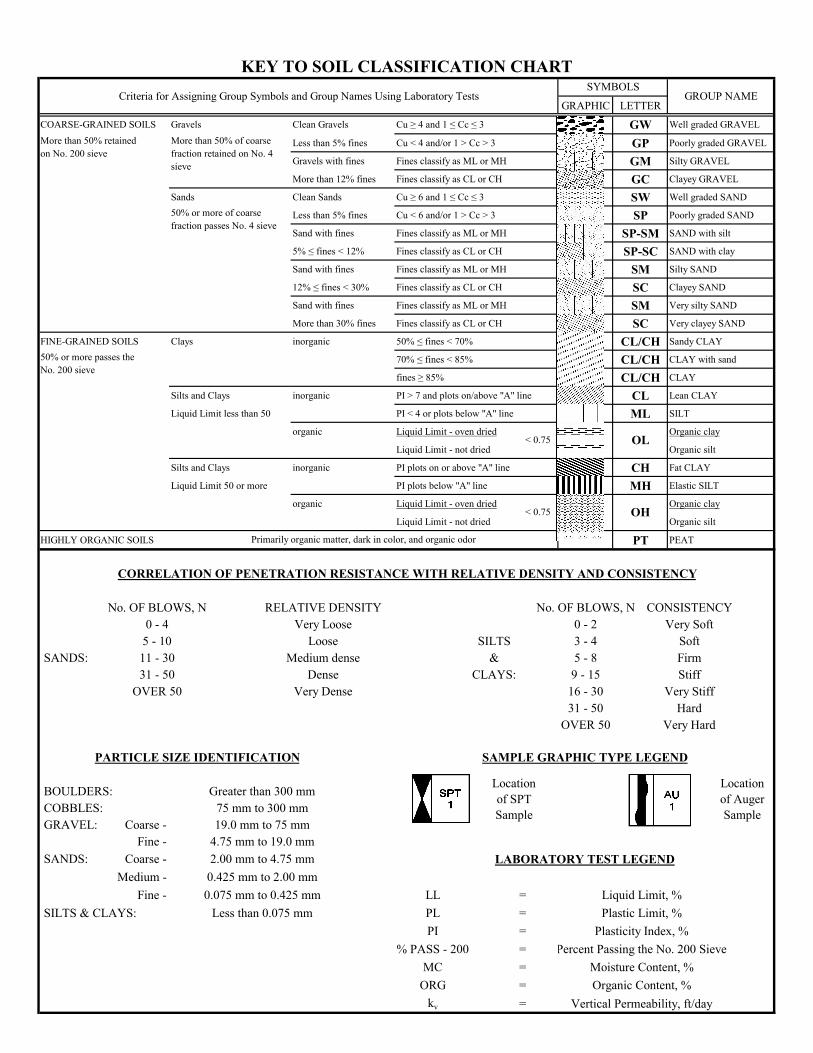
GRAPHIC LETTER
COARSE-GRAINED SOILS Gravels Clean Gravels Cu ≥ 4 and 1 ≤ Cc ≤ 3 GW Well graded GRAVEL
Less than 5% fines Cu < 4 and/or 1 > Cc > 3 GP Poorly graded GRAVEL
Gravels with fines Fines classify as ML or MH GM Silty GRAVEL
More than 12% fines Fines classify as CL or CH GC Clayey GRAVEL
Sands Clean Sands Cu ≥ 6 and 1 ≤ Cc ≤ 3 SW Well graded SAND
Less than 5% fines Cu < 6 and/or 1 > Cc > 3 SP Poorly graded SAND
Sand with fines Fines classify as ML or MH SP-SM SAND with silt
5% ≤ fines < 12% Fines classify as CL or CH SP-SC SAND with clay
Sand with fines Fines classify as ML or MH SM Silty SAND
12% ≤ fines < 30% Fines classify as CL or CH SC Clayey SAND
Sand with fines Fines classify as ML or MH SM Very silty SAND
More than 30% fines Fines classify as CL or CH SC Very clayey SAND
FINE-GRAINED SOILS Clays inorganic 50% ≤ fines < 70% CL/CH Sandy CLAY
70% ≤ fines < 85% CL/CH CLAY with sand
fines ≥ 85% CL/CH CLAY
Silts and Clays inorganic PI > 7 and plots on/above "A" line CL Lean CLAY
Liquid Limit less than 50 PI < 4 or plots below "A" line ML SILT
organic Liquid Limit - oven dried Organic clay
Liquid Limit - not dried Organic silt
Silts and Clays inorganic PI plots on or above "A" line CH Fat CLAY
Liquid Limit 50 or more PI plots below "A" line MH Elastic SILT
organic Liquid Limit - oven dried Organic clay
Liquid Limit - not dried Organic silt
HIGHLY ORGANIC SOILS PT PEAT
No. OF BLOWS, N RELATIVE DENSITY No. OF BLOWS, N CONSISTENCY0 - 4 Very Loose 0 - 2 Very Soft
5 - 10 Loose SILTS 3 - 4 Soft SANDS: 11 - 30 Medium dense & 5 - 8 Firm
31 - 50 Dense CLAYS: 9 - 15 StiffOVER 50 Very Dense 16 - 30 Very Stiff
31 - 50 HardOVER 50 Very Hard
BOULDERS: Greater than 300 mm COBBLES: 75 mm to 300 mm GRAVEL: Coarse - 19.0 mm to 75 mm
Fine - 4.75 mm to 19.0 mm SANDS: Coarse - 2.00 mm to 4.75 mm
Medium - 0.425 mm to 2.00 mmFine - 0.075 mm to 0.425 mm LL = Liquid Limit, %
SILTS & CLAYS: Less than 0.075 mm PL = Plastic Limit, %PI = Plasticity Index, %
% PASS - 200 = Percent Passing the No. 200 SieveMC = Moisture Content, %
ORG = Organic Content, %kv = Vertical Permeability, ft/day
50% or more passes the No. 200 sieve
50% or more of coarse fraction passes No. 4 sieve
< 0.75
< 0.75
KEY TO SOIL CLASSIFICATION CHARTGROUP NAME
More than 50% retained on No. 200 sieve
More than 50% of coarse fraction retained on No. 4 sieve
SYMBOLSCriteria for Assigning Group Symbols and Group Names Using Laboratory Tests
OL
OH
Primarily organic matter, dark in color, and organic odor
PARTICLE SIZE IDENTIFICATION
LABORATORY TEST LEGEND
CORRELATION OF PENETRATION RESISTANCE WITH RELATIVE DENSITY AND CONSISTENCY
Location of Auger Sample
SAMPLE GRAPHIC TYPE LEGEND
Location of SPT Sample

Summary Report of a Geotechnical Site Exploration September 8, 2011 LaCrosse Citrus Repository LaCrosse, Alachua County, Florida GSE Project No. 11248
6-1
6.0 LIMITATIONS
6.1 Warranty This report has been prepared for our client for his exclusive use, in accordance with generally accepted soil and foundation engineering practices, and makes no other warranty either expressed or implied as to the professional advice provided in the report. This exploration was confined to the zone of soil likely to be stressed by the proposed construction. Our work did not address the potential for surface expression of deep geological conditions, such as sinkhole development related to karst activity. If desired, this type of evaluation could require a more extensive range of field services than performed as part of this geotechnical investigation.
6.2 Auger and SPT Borings
The determination of soil type and conditions was performed from the ground surface to the maximum depth of the borings, only. Any changes in subsurface conditions that occur between or below the borings would not have been detected or reflected in this report.
Soil classifications that were made in the field are based upon identifiable textural changes, color changes, changes in composition or changes in resistance to penetration in the intervals from which the samples were collected. Abrupt changes in soil type, as reflected in boring logs and/or cross sections may not actually occur, but instead, be transitional.
Depth to the water table is based upon observations made during the performance of the SPT borings. This depth is an estimate and does not reflect the annual variations that would be expected in this area due to fluctuations in rainfall and rates of evapotranspiration.
6.3 Site Figures
The measurements used for the preparation of the figures in this report were made with a fiberglass tape and by estimating distances from existing structures and site features. Figures in this report were not prepared by a licensed land surveyor and should not be interpreted as such.
6.4 Unanticipated Soil Conditions The analysis and recommendations submitted in this report are based upon the data obtained from soil borings performed at the locations indicated on the Boring Location Plan. This report does not reflect any variations that may occur between these borings. The nature and extent of variations between borings may not become known until excavation begins. If variations appear, we may have to re-evaluate our recommendations after performing on-site observations and noting the characteristics of any variations.

Summary Report of a Geotechnical Site Exploration September 8, 2011 LaCrosse Citrus Repository LaCrosse, Alachua County, Florida GSE Project No. 11248
6-2
6.5 Misinterpretation of Soil Engineering Report GSE Engineering & Consulting, Inc. is responsible for the conclusions and opinions contained within this report based upon the data relating only to the specific project and location discussed herein. If others make the conclusions or recommendations based upon the data presented, those conclusions or recommendations are not the responsibility of GSE.

Summary Report of a Geotechnical Site Exploration September 8, 2011 LaCrosse Citrus Repository LaCrosse, Alachua County, Florida GSE Project No. 11248
FIGURES
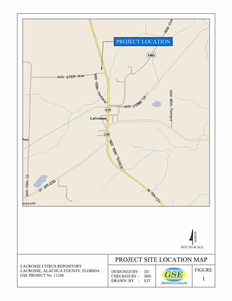
FIGURE
1
NOT TO SCALE
PROJECT SITE LOCATION MAP
NO
RTH
DESIGNED BY: JJJCHECKED BY : JBNDRAWN BY : EJT
PROJECT LOCATION
LACROSSE CITRUS REPOSITORYLACROSSE, ALACHUA COUNTY, FLORIDAGSE PROJECT No. 11248
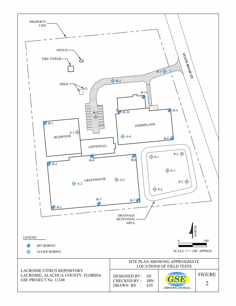
LEGEND :
FIGURE
2
SITE PLAN SHOWING APPROXIMATELOCATIONS OF FIELD TESTS
LACROSSE CITRUS REPOSITORYLACROSSE, ALACHUA COUNTY, FLORIDAGSE PROJECT No. 11248
DESIGNED BY: JJJCHECKED BY : JBNDRAWN BY : EJT
0 100'
SCALE: 1" = 100' APPROX.
NO
RTH
SPT BORING
AUGER BORING
B-3
A-2
B-2B-4
A-3
B-6
B-7B-5
P-4
P-1P-2
P-5
A-4
B-10
B-8
B-9
B-11
R-1
R-2
R-3
B-1
A-1
P-3
OFFICE
FIRE TOWER
SHED
BUDWOOD
(OPTIONAL)
GREENHOUSE
GERMPLASM
DRAINAGERETENTION
AREA
PROPERTYLINE
STATE R
OA
D 121


![[Jean Blondel, Richard Sinnott, Palle Svensson] Pe(BookFi.org)](https://static.fdocuments.in/doc/165x107/55cf9717550346d0338fb8f6/jean-blondel-richard-sinnott-palle-svensson-pebookfiorg.jpg)