
Elements of Axiomatic Design
29
Elements of Engineering Design page 1 – draft 29 March 2006 © Christopher A. Brown, Cazenovia, NY Elements of Axiomatic Design a simple and practical approach to engineering design Draft: 29 March 2006 Christopher A. Brown © Christopher A. Brown, Cazenovia, NY 2006 Table of contents Forward 1. Discovery of the axioms 2. What this book does 3. Engineering Design what it is and why it is important 4. Everyone can benefit from axiomatic design 5. Can engineering design be a science Chapter 1. An Introduction to Axiomatic Design 1. The main elements of axiomatic design 2. Design Axioms 2.1 Axiom one: Maximize Independence 2.2 Axiom two: Minimize Information – Maximize Success 3. Design Structures 3.1 Design Domains: Lateral Decomposition 3.2 Design Hierarchies: Vertical decomposition 3.2.1 Collectively Exhaustive and Mutually Exclusive (CEME) 4. Process 4.1 Zigzagging Decomposition 4.1.1 Importance of Domains and Upper level FRs 4.1.2 Using Generic DPs at the upper levels 4.1.3 Checks at each level 4.1.3.1 Checking for axiom one 4.1.3.2 Checking for axiom two 4.2 Physical Integration Chapter 2. The Design Axioms 1 Axiom one: Maximize Independence 1.1. kinds of coupling 1.1.1 sequential 2 Axiom two: Minimize Information Chapter 3. The Design Structures 1 Lateral Decomposition 2 Vertical Decomposition Chapter 4. The Design Process 1 Zigzagging decomposition 1.1 DPs as constraints – keeping options open 1.2 Solution neutral environment 2 Physical Integration 2.1 physical integration – functional independence
description
Elements of Axiomatic Design
Transcript of Elements of Axiomatic Design
Elements of Engineering Design page 1 – draft 29 March 2006 © Christopher A. Brown, Cazenovia, NY
Elements of Axiomatic Design a simple and practical approach to engineering design
Draft: 29 March 2006 Christopher A. Brown
© Christopher A. Brown, Cazenovia, NY 2006 Table of contents Forward 1. Discovery of the axioms 2. What this book does 3. Engineering Design what it is and why it is important 4. Everyone can benefit from axiomatic design 5. Can engineering design be a science Chapter 1. An Introduction to Axiomatic Design 1. The main elements of axiomatic design 2. Design Axioms 2.1 Axiom one: Maximize Independence 2.2 Axiom two: Minimize Information – Maximize Success 3. Design Structures 3.1 Design Domains: Lateral Decomposition 3.2 Design Hierarchies: Vertical decomposition 3.2.1 Collectively Exhaustive and Mutually Exclusive (CEME) 4. Process 4.1 Zigzagging Decomposition 4.1.1 Importance of Domains and Upper level FRs 4.1.2 Using Generic DPs at the upper levels 4.1.3 Checks at each level 4.1.3.1 Checking for axiom one 4.1.3.2 Checking for axiom two 4.2 Physical Integration Chapter 2. The Design Axioms 1 Axiom one: Maximize Independence 1.1. kinds of coupling 1.1.1 sequential 2 Axiom two: Minimize Information Chapter 3. The Design Structures 1 Lateral Decomposition 2 Vertical Decomposition Chapter 4. The Design Process 1 Zigzagging decomposition 1.1 DPs as constraints – keeping options open 1.2 Solution neutral environment 2 Physical Integration 2.1 physical integration – functional independence

Elements of Engineering Design page 2 – draft 29 March 2006 © Christopher A. Brown, Cazenovia, NY
Chapter 5. Closing remarks 5.1 creativity developing good FRs 5.2 everyday applications Foreword
Everyone does some kind of design everyday. It is part of the nature of humans. Planning, outlining, scheduling, and scheming are all forms of design. The purpose of this book is to teach readers how to apply axiomatic design to making all their designs better. Without giving much thought to the design of the workspace, you might position folders on your desk so that things that need attention are given separate positions. That way you think they are obvious and will get the attention they need. Eventually there are too many things that need attention and there is not enough space, so the folders get piled up. Is this a good design of a work space? Probably not, as you can’t reliably find what you need to work on next because it is buried under something else. The piles tend to couple the work in the folders, because the access and attention to the folders on the bottom of the piles is limited by the folders on the top. This design could be improved by some kind of file separator or trays which would allow access to the folders independently. These solutions both improve the independence and reduce the information in the design of the workspace. An engineering team was designing a plasma torch, which is used for cutting metals. It needed a cooling system, which required a water pump and a fan. In an effort to conserve parts an engineer on the team decided to use one electric motor and run both the pump and fan off the same shaft from this one motor. Was this a good design? It seemed like it, until the position of some of the plasma generation components were adjusted by another member of the team and it became awkward and expensive to run both components off the same motor. Finally the pump and the fan had to have their own electric motors. This was a better design from the point of view of maximizing independence. It also turned out to be less expensive and less complicated. Now the pump and fan components could be positioned independently and the motor speeds could be adjusted independently and the two motors could be selected independently for the two different requirements. These are examples of design problems that can be addressed by Suh’s design axioms. Both of these initial solutions were hampered by unnecessary physical linking of two functions. In both cases the decoupling was made possible by extra physical components. Clearly many engineers need to resist the temptation of thinking that fewer components are always better. Design problems traditionally could be said to come in two types:
A. developing candidate solutions for accomplishing the design objectives B. selecting between the candidate solutions.

Elements of Engineering Design page 3 – draft 29 March 2006 © Christopher A. Brown, Cazenovia, NY
These two problem types can naturally be decomposed, or broken down, possibility in a variety of ways. For example, stating the functional requirements for the design and the constraints on the potential solutions are decompositions of, or steps towards, developing candidate solutions. Decompositions of selection process could be the different kinds of disciplinary specific analyses, e.g., performing stress analysis to assure that the solution is sufficiently strong, are decompositions of selection. The solutions to both types problem are handled by the axiomatic design process. The selection of candidate solutions requires a certain kind of systematic description of the problem that provides the proper context for formulating candidate solutions. This description and context are provided by the domains and hierarchies of axiomatic design structures. The selection of the best solution requires ranking candidates by the goodness of the design solution. The goodness of a design solution can be evaluated by compliance with Suh’s two design axioms, which are:
Axiom one. maximize the independence of the functional elements; and Axiom two. minimize the information content of the design (i.e., maximize the probability of success).
These axioms can be applied even to relatively mundane, everyday coping problems, as well as to advanced engineering design. Design solutions need to be developed based on customer needs which are translated into functional requirements. The functional requirements need to be described in a solution neutral way so that none of the potentially viable design parameters i.e., physical embodiments for fulfilling the functional requirements, are excluded until they can be assessed by the axioms. The axiomatic design process described in this book explains how to do this.
Suh’s design axioms are like scientific laws. They cannot be proven, but no one has seen an exception to them. These axioms are the laws that govern good designs. Having two axioms to tell good designs from bad ones is a great simplification to previous design evaluation methods. These axioms can be used by everyone every day.
For engineers the design axioms transform the field of engineering design from a mixture of intuition, experience, art, and analysis to a scientific discipline in that there are simple, compact rules that can be applied to solving a wide range of design problems. Just as Newton’s laws apply to solving a wide variety of problems, from planetary motion to apples falling, the design axioms apply to a designing anything from your daily agenda to the crew survivability system for an orbital space plane. Neither Newton’s laws nor Suh’s axioms can be proven. Their validity relies on the lack of observations of violations. 1. The discovery of design axioms
Nam Suh, an engineering professor at MIT, discovered two design axioms in the 1970s. Many engineers have since found that these axioms are to engineering design what Newton’s laws of motion are to engineering mechanics – they are the keys to
Elements of Engineering Design page 4 – draft 29 March 2006 © Christopher A. Brown, Cazenovia, NY
solving problems in their respective fields. Some engineers do not agree that there is an axiomatic approach to solving design problems – I believe that their disagreement is merely because they do not yet understand axiomatic design well enough, and maybe this book can help. This axiomatic approach to design is still relatively new, especially compared with things like Newtonian mechanics. We should always expect some disagreement about new concepts. Challenges to new concepts can be healthy and strengthen the new concepts. In this book axiomatic design is developed so that anyone should be able to understand and apply axiomatic design.
Based on the belief that design axioms existed, Professor Suh and his group at MIT began a quest to discover them during the 1970s. They made a list of the six hypothetical, or candidate, axioms. These candidate axioms were based on elements that Suh and his group felt were found in all good designs. In any kind of problem solving the simplest solution is the best. Therefore the best list of axioms would be the shortest list that was comprehensively exhaustive, and where each axiom was independent of each other. With some study the initial list of candidate axioms was eventually shortened to two: first maximize the independence of the functional elements, and then minimize the information content.
This discovery of the design axioms was a tremendously important step for the design process. It makes the design process much easier to understand and to apply and to teach. The discovery of the axioms created a scientific discipline for design in the same way that mechanics and thermodynamics are scientific disciplines. The practice of design based on axioms became a scientific discipline in the sense that there is a self-consistent, axiom-based logic that leads to good solutions for design problems. This means that design can be taught as a scientific discipline based on the axioms, moving design beyond a field of study that relies too heavily on experience.
Prof. Suh’s books: The Principles of Design (Oxford Press 1990) and Axiomatic Design (2001) are excellent and complete descriptions of axiomatic design. Engineering graduate courses at select engineering schools around the world use these texts. Many undergraduate engineering students find parts of them to be challenging. Everyone I’ve worked with finds that the material in Suh’s axiomatic design books is easier to grasp with accompanying lectures and discussion. Much of what is written here is based on these books and on lectures developed over the past fifteen years to assist people in the assimilation of the axiomatic design concepts. This book can be used on its own and can serve as a helpful introduction to Prof. Suh’s books. 2. What this book does
The emphasis of this book is on how to apply of Axiomatic Design. The content of this book goes beyond Suh’s books in some areas although it skips some of the math and theoretical developments. Suh’s books also have several chapters on case studies. This book includes much of what I have learned using and teaching Axiomatic Design over the last quarter century. The intent is that this book also should be easier to understand for most people than Suh’s books.
This book should teach you what could be called the grammar of engineering design. You will have to supply the vocabulary – the knowledge of your subject – of what it is you are designing. You can read Strunk and White and learn the elements of style – English grammar – for writing well. Nonetheless the writer needs to supply the
Elements of Engineering Design page 5 – draft 29 March 2006 © Christopher A. Brown, Cazenovia, NY
vocabulary and the content. In this book you can learn the elements of engineering design using axioms. However, if you don’t know anything about aerodynamics, you still won’t be able to design airplanes. If you do know aerodynamics, or if you are learning aerodynamics, then this book will help you to design better airplanes faster. And if you master the elements of design and combine this with knowledge of aerodynamics, then you will find the best solution to the design problems and design the best airplanes.
Understanding engineering design will help you recognize good designs more easily and help you to design things better yourself – whatever it is you are designing or selecting – from airplanes and medical devices, to family trips and the processes of homemaking. The selection of which things to buy, software and how to configure it, the development of organizations and businesses, the organization our activities each day – all can be improved by using the elements of engineering design.
Axiomatic design is a powerful approach to any kind of design activity, like scheduling, organizing, and planning. Complying with the axioms will produce designs, systems, organizations, and plans that get better results – things that have the best chance of achieving their objectives. The axioms can be applied to any kind of design activity, even though they were originally developed for engineering design.
The objective of engineering design is to fulfill some function that satisfies a societal or customer need. As the architect Louis Sullivan said at the beginning of the twentieth century, “form follows function.” This doctrine of functionalism emphasizes utility. Engineering designs are formulated to achieve objectives. Axiomatic design first of all is a functionally based design system.
This book is primarily intended for people actively involved in technical or engineering type projects that require a systematic approach to design in work or school. For the most part these are people like engineers and engineering, and technical students in college and high school. However, this book could also be useful for business students, not only to better understand the technology in their businesses, but also to design businesses and organizational systems. Not all engineers agree that axiomatic design is the best approach to engineering design. I think it is. In 1980 I learned about it from its originator, Prof. Nam Suh of MIT, and I’ve been using it in some form ever since in all aspects of my professional and personal life. And I’ve been teaching it to engineering students and practicing engineers for about fifteen years. My students have told me how axiomatic design changes the way they think about everything, and how it has lead to patents and saved money for their companies and clients, is some cases hundreds of thousands or even millions of dollars. 3. Engineering Design: what it is and why it is important
Engineering design is the most important process for shaping the modern world. Everything we do involves some kind of interaction with something that has been designed. Even if we are not engineers we constantly design things in our everyday life, often without thinking about it. Planning our daily agenda, meals, trips to do errands, the organization of our homes and businesses, that is, any kind of planning or organization can all be considered some form of engineering design.
Engineering design is the process of dreaming of things that never were and asking why not. It involves conceiving, planning, analyzing, comparing, and selecting components and systems that fulfill some desired function. Engineering design is
Elements of Engineering Design page 6 – draft 29 March 2006 © Christopher A. Brown, Cazenovia, NY
functionally based and objective oriented. Engineering design is not just drawing or drafting. Engineering design first is the process of developing concepts. This is where much of the substantive content of the design begins.
Drafting, i.e., creating engineering drawings, which often gets confused with designing, is strictly speaking just a process that is used to render certain kinds of engineering design concepts on paper or on a computer for development, storage, and communication. Drafting is part of the engineering design process that does not necessarily involve any creativity. The drafting process does help the designer to focus on design details and how they will integrate physically. Engineering design encompasses much more than drafting.
Nearly everything around us and nearly everything we interact with is designed – houses, cars, highways, bridges, airplanes, security systems, software, clothes, organizations, schools, recreation facilities, sports equipment, entertainment systems, government, and businesses – you name it. The method of design that is used to conceive, develop and select these designs thereby influences, or colors, all these things. Therefore there are few things, if any, that have more impact on our material and organizational existence than the method that is used for engineering design.
Even if you are not designing an airplane, the method that you use to design things, like, your vacation, work, daily activities, impacts how successful you are at doing these things.
Most people don’t think about the method they use to design their activities. Many of these activities could be done better, accomplishing the objectives, reaching the goals more often, if an axiomatic design method is used. There is no more important tool in the modern world that the method by which we create functional designs.
Often the method we use to design things is intuitive. We are a species of designers, and we can design many things adequately using our intuition alone – without considering any special method for the design process. After all we are the homo-sapiens. We are the toolmakers – the builders – the planners – the engineers – the designers. A seemingly inherent ability to conceive and realize complex and varied engineering design is the most important thing distinguishing our species from all the others. 4. Everyone can benefit from axiomatic design
Everyone can apply axiomatic design to their design, planning, and to their organizational processes and projects. Students at every level can apply axiomatic design to their school projects.
Some engineering professors might claim that you can’t study engineering design until you know enough science and mathematics. This is nonsense. This kind of professor emphasizes the analysis component of the design process. Once sophisticated mathematics was necessary for many kinds of analysis, now many kinds of complex analysis are performed by software that makes the complexity transparent to the user.
We are a species of designers. People start designing before they can speak. Babies quickly learn how manipulate the people around, to accomplish functions they want done. They know they can get certain reactions by doing things like crying and smiling. Everyone already understands an essential part of design – how to vary inputs to

Elements of Engineering Design page 7 – draft 29 March 2006 © Christopher A. Brown, Cazenovia, NY
get a desired output, or function. There are many situations where axiomatic design can be applied qualitatively, using no mathematics at all, and this book will explain how.
Everyone should study engineering design in public schools, the way we now study science. From grade school through high school we all learned something about science and the scientific method. Few of my classmates ever practiced science, although everyone practices engineering design in some form. Everyone would benefit from understanding how to use axiomatic design.
When a design challenge is new, or old and problematic, or large, or complex, enough a formal approach to the engineering design process is obviously necessary. Sometimes when the design problem appears simple, maybe because of a lot of experience, people think that best solution to a design problem is obvious and that a formal design method is not necessary. Be careful if you decide not to use the elements of axiomatic design. Conventional wisdom in design can be too conventional and not too wise – clearly poor attributes for most designs. At least there can some comfort in using a formal approach to check even those things that seem obvious. It can be useful for practice and maybe as a verification of the process. However, if the elements of axiomatic design are applied properly, in a solution neutral environment, free from previous solutions, substantial advances can be made. There are many examples where a less experienced engineer has developed a better design because of application of the elements of axiomatic design in a solution neutral environment. 5. Engineering design can be a science
When we say that a field of study is a science discipline we mean that there is a self-consistent set of underlying rules that can be used to solve a wide range of problems and explain a broad range of phenomena in that field. There are great advantages when engineering fields can be considered to be scientific disciplines. Scientific disciplines are fields of study that are governed by a few simple axioms, like Newton’s Laws for engineering mechanics or Maxwell’s equations for electrical engineering.
The scientific method is the process of studying things that are and trying to understand why they are that way. It involves proposing theories, testing them and then revising them. The objective of the scientific method is to find the simplest rules, i.e., laws or axioms that can explain the broadest range of observations. It is the discovery of these axioms that govern phenomena in a field that is particularly important.
Engineering design is the process of conceiving of new things and figuring out how to make them. Part of the “figuring out” is engineering analysis. The analysis is often based on scientific disciplines. The real purpose of engineering analysis is to support design as a component in the design process. Analysis by itself is not design. Analysis allows engineers versed in some field to predict the future of things that are performing in that field. For example, an engineer versed in the field of structural engineering could make a prediction like: “If you build the bridge this way, it will support trucks this heavy, but will collapse under heavier trucks.” Analysis is not design. Before the bridge could be analyzed it had to be conceived. The axioms can be applied with the conception of a design.
Historically engineering design itself could not be considered a scientific discipline. It was taught, and mostly still is taught, based on experience, just as we might imagine that mechanics was taught before Newton. Suh’s discovery of the governing

Elements of Engineering Design page 8 – draft 29 March 2006 © Christopher A. Brown, Cazenovia, NY
axioms for engineering design in provided the basis for establishing engineering design as a scientific discipline. One advantage of a scientific discipline over fields that do not have clear axioms is that it is much easier and more efficient to teach and learn a scientific discipline than it is to teach or to learn a field that relies heavily on experience. In this context it is difficult to overstate the importance of the discovery of the design axioms.
Practically, in addition to developing superior designs, the axioms speed and facilitate the design process like nothing else can. Examples can be found where the design processes are shortened by a factor of two or greater and the resulting designs are superior.
When design is done with a team, people often become irrationally strong proponents of portions of the design that they thought of. Designs can be like babies. Designs often look better to the people who made them than they do to people with more objective points of view, or to people with other “design babies” that they are advocating. Discussions of design alternatives often get slowed by people arguing in favor of their designs when there is no good way of evaluating and comparing them. The axioms provide the basis for evaluating design. A former doctoral student (E.M.Shipluski) noted after applying axiomatic design at GE that the axioms allow design teams to move “from argument to analysis.” Chapter 1 An Introduction to Axiomatic Design
The purpose of this book is to teach the essential elements of axiomatic engineering design so that they can be applied to designing and planning anything better than could be done without the axioms. Designs and plans are intended to accomplish functions. Designs are created to get something done – fulfill a purpose. Everyone who needs to get things done can benefit from understanding how to do axiomatic design. This book teaches the elements of axiomatic design and how to use them to create, or even just to select, better things – anything – from consumer products, to manufacturing systems, businesses, organizations, filing systems, vacations, and your daily agenda.
The most effective way to learn how to follow and effectively utilize a process, like axiomatic design, is by using it. You should start using it early in the learning activity, at least in some elementary form. In this way the process can be appreciated, and perhaps some benefit can be derived from it, which should increase the motivation to learn more about it. This first chapter introduces all the basic elements of axiomatic design and gives an overview about how they are used. This should be enough to get started. The following chapters go into more depth, supplying details and further elaborations for increasing the breadth and depth of developing solutions to design problems.
This first chapter describes the entire axiomatic design process concisely. It is intended to be read sequentially in order to understand how the full process works. By the time you finish the first chapter you should have a working knowledge of axiomatic

Elements of Engineering Design page 9 – draft 29 March 2006 © Christopher A. Brown, Cazenovia, NY
design. The later chapters then could be read sequentially as well, or used as reference material, reading only the sections needed to better understand some element of axiomatic design. 1. The Three Primary Elements of Axiomatic Design The three primary elements that compose axiomatic design are the axioms, the structures, and the processes. They are the basis for understanding and applying axiomatic design.
Each of these primary elements can be decomposed into two secondary elements as shown in table 1.
The axioms are the basis for axiomatic design. They supply the foundation for the design process and drive the other two elements. The other two primary elements, structures and processes, supply the means to apply the axioms systematically to any design. In order to apply the axioms the design must have certain structures. The creation of these structures is facilitated by certain processes. Table 1. The primary and secondary elements of design Primary Secondary Notes
1.1 Maximum Independence Avoids iteration and unintended consequences
1. Axioms
1.2 Minimum Information Maximizes chance of success 2.1 Design Domains Decomposes laterally by type 2. Structures 2.2 Design Hierarchies Decomposes vertically by level of
detail 3.1 Zigzagging decomposition Developing detail down through
the hierarchic domains 3. Processes
3.2 Physical integration Integrating detail up through the physical domain
2. Design Axioms The objective of this section is to explain the design axioms. Understanding the design axioms and how to apply them is the foundation of axiomatic designs, and the superior and innovative designs that result.
The axioms are the rules that all good designs comply with – the rules that govern good design. These rules need to be applied at each level of the design and each stage in the design creation process. They are good not only for designs that get worked out on paper or on a computer, can be applied to anything including a vacation or interpersonal relationships. Whenever you get involved in applying the axioms to a design or to some kind of planning or organizing, you will first need to configure a description of whatever it is, i.e. structure, so that you can apply the axioms. 2.1 Axiom One: Maximize Independence This first axiom is probably the most useful and beneficial part of axiomatic design. The independence axiom is about creating a design that is adjustable and controllable by avoiding unwanted coupling. Unwanted coupling results in unintended consequences and makes a design difficult to control or adjust. When two things are coupled it means that they cannot be adjusted or changed independently, i.e., a change in one influences the other to bring about a change in it too.

Elements of Engineering Design page 10 – draft 29 March 2006 © Christopher A. Brown, Cazenovia, NY
A classic example is a conventional water faucet that can be found still on many sinks (Suh 1990). It has one handle for adjusting the flow of the hot water and another adjusting the flow of the cold water. All the water flows through one faucet that mixes the hot and the cold water together before it comes out into the sink.
The problem with this faucet design is that adjustment of the amount of the water coming out of the faucet is coupled with the adjustment of the temperature of the water. Adjusting either the cold or the hot water handles changes both the flow and the temperature. With this kind of conventional system the flow and the temperature cannot be adjusted, or controlled, independently, which is another way of saying that the adjustment of the water temperature and the flow are coupled.
The problem with coupled designs is that some non-productive iteration will generally be required to reach the desired result. If one functional requirement of the design had been to control the water temperature and another had been to control the flow, then this design would violate axiom one. In the case of the water faucet a satisfactory temperature and flow rate can rarely be achieved on the first try, at least not without some luck. The non-productive iteration might go like this: a first guess at the adjustment of the two valves is made while observing the flow rate, then the temperature is tested by sticking a hand into the flow and a subsequent adjustment is made to one or the other valve to adjust the temperature, this adjustment changes the flow rate, so a compensating adjustment is made to make the flow rate acceptable, which could take the temperature out of the acceptable range. The consequences of this iteration to adjust flow and temperature are not to severe, a few extra moments for washing hands, a little water splashed onto the clothes if the flow rate gets to high, or a hand that is too warm or cold for a moment. Obviously it would be better if this kind of iteration could be avoided, especially where time and cost are critical.
A coupled design will be difficult to adjust or control and suffer from unintended consequences because every time you adjust one thing, something else that is important goes out of adjustment. The only way you may be able to adjust everything is to iterate, and even then there is no guarantee that an iteration strategy will converge on an acceptable result. This iteration is a waste of time. Fully independent designs that comply with axiom one can be adjusted without iteration.
In order to detect undesirable coupling early in the design process, in other words, in order to apply axiom one, the components making up the design needs to be structured or organized so that the coupling is obvious. With the proper structure to the design undesirable coupling can be designed out. Whether or not a design is coupled depends on what the desired functions, or functional requirements (FRs), are, and how they are matched with physical components of the design or design parameters (DPs). FRs and DPs are elements of two different design domains, which are discussed in more detail in the section on structures below and later in the chapter on structures.
For now let’s note that there are three basic kinds of coupling to consider in design:
1) FR-FR coupling between functional requirements, 2) FR-DP coupling between functional requirements and design parameters, and 3) DP-DP coupling between the design parameters. .

Elements of Engineering Design page 11 – draft 29 March 2006 © Christopher A. Brown, Cazenovia, NY
The conventional faucet design discussed above is an example of unwanted FR-DP coupling. The structure can be introduced to the faucet design this way, supposing the highest level functional requirement (FR0) is to control the water supply for washing hands. This might be decomposed into two components, or lower level functional requirements: FR1) control the water temperature and FR2) control the water flow rate. In the coupled design example there are two design parameters at this level DP1) the hot water control valve, and DP2) the cold water control valve.
Sometimes it is not possible to make FR-DP components of a design independent. Then it is important to know where the interactions are, and what consequences they will have on controllability and to be able to compare competing designs on the amount of coupling. Designs that are quasi-coupled can be adjustable without iteration if the correct order of adjustment is selected. This is explained more fully in chapter two. 2.2 Axiom Two: Minimize Information – Maximize Success
Axiom two is called the information axiom, and it states that of all the designs that satisfy the independence axiom equally, the best design is the one with the least information. Note that there is an order in the process or applying the axioms, first apply axiom one, then apply axiom two. In practice most of the effort is put into satisfying axiom one. There may not be more than one design that satisfies axiom one, in which case there is no need to apply axiom two and axiom two is sometimes not considered. Another way of saying minimize the information is to maximize the probability of success. In the sense that it is used in axiom two, information is based on the ratio of the total number of possible outcomes a design would produce, to the number of those outcomes that would satisfy the functional requirements. At a minimum this ratio is one. The larger this ratio the worse the design, because its probability of success is lower. Intuitively axiom two can be understood in some situations as selecting the design that has the minimum amount of instructions. If more instructions are required to fulfill a requirement in a design, then the chance that all the instructions will be followed correctly is smaller. In this way the information axiom is obviously useful in designing a process, like giving someone driving directions, or for making something as in a manufacturing process. Axiom two is used to select the best design from alternatives that comply with axiom one. This means that in order for the information axiom to be useful, there must be at least two alternatives that comply equally with the independence axiom.
An example of a violation of axiom two are driving directions that may be good from the perspective of describing the shortest route or avoiding traffic, but are so intricate that you have concerns about being able to follow them. New England seems to have plenty of these kinds of things: “…turn right just after where the school house used to be, then take a left about a hundred yards before you get to the covered bridge...” With every turn you must take or land mark you need to recognize there is a chance of an error. The information content of the directions is high, i.e., the probability of success is low, and the risk of getting lost is great. Often the best directions are the simplest.
In manufacturing there are some well known generalities that are consistent with axiom two, for example, a design that allows a broader tolerance will have a greater probability of being manufactured within that tolerance. Designs with broader tolerances will more often be able to fulfill their functional requirements after some wear than

Elements of Engineering Design page 12 – draft 29 March 2006 © Christopher A. Brown, Cazenovia, NY
designs with tighter tolerances. Axiom two can be applied quantitatively in manufacturing environments where sufficient data should be available on process capabilities. Axiom two can also be used in process planning and the selection of machines and the order of operation. To use axiom two in any situation remember to select the biggest target and to keep the instructions short. Of course you can’t just make the target large by declaration, or make the instructions short just by deletion. The design needs to be such that the tolerances can be broad and the functions are still achieved. The design also needs to be such that short instructions are appropriate for successful operation. 3. Structures
The objective of this section is to explain how a design should be structured in order to apply the axioms. Understanding the structure of the design is a prerequisite for creating a design that complies with the axioms. The structure allows designers to create and communicate designs more effectively and completely. The structure also allows the designer to understand the consequences of changes on the design.
The structure is made up laterally of design domains and vertically of hierarchies of detail in the domains. The design domains essentially are just different ways of describing the design. Good descriptions are essential to good designs, they are also essential to the communication and negation that are part of developing good designs. The structure is a decomposition of the design into domains and hierarchies of detail.
The structure is created so that the axioms can be applied thoroughly and systematically to all the aspects of the design. In other words the function of having to apply the axioms to the design, drives the design to be structured in a certain way. The form of the design process itself follows the functions required during the process. The axiomatic design process is designed based on the axioms – it is self consistent.
The first part of the structure in design is the domains, the different kinds of description. The most important kinds of domains are functional and physical – describing designs by what they do or by what they look like. The second part is to show the hierarchical decomposition of the design, dividing the design into manageable systems of components at different levels of detail. The decompositions must be logical in two ways so that, 1) the entities fit into the right categories or domains, and 2) the level of detail flows logically in the hierarchy from parent to child.
The decomposition is a kind of taxonomy of the design. In the elements of the different design domains are connected to each other. These connections are evaluated by the axioms. In design decompositions, just as in biological taxonomies, different systems are possible for the decompositions or classifications, and some will work better than others. 3.1 Design Domains – Lateral Decomposition The design domains are like spaces, or zones, on the playing field for the a game we could call design. The domains are the different kinds of entities that make up the design. The two most commonly used domains in the design exercise are the Functional and Physical Domains, which describe respectively the function of the design and physically how that function is accomplished. Each element of the Functional Domain should directly drive an element of the Physical Domain so that there is a one-to-one
Elements of Engineering Design page 13 – draft 29 March 2006 © Christopher A. Brown, Cazenovia, NY
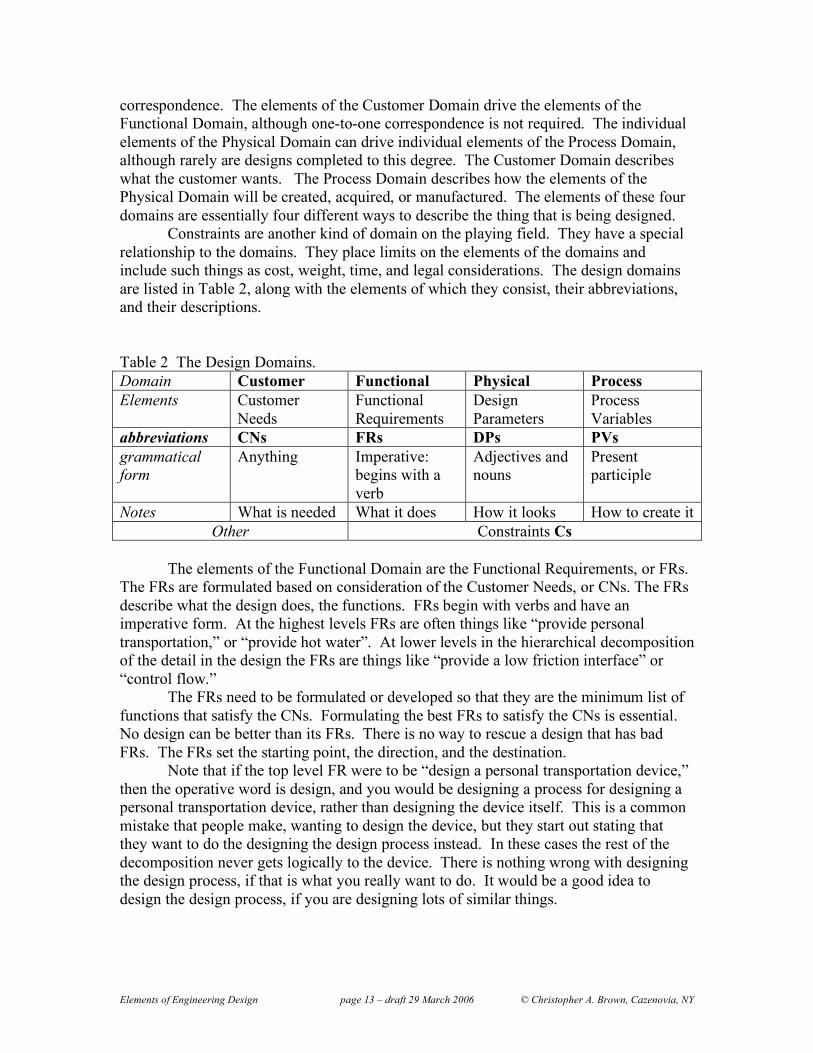
correspondence. The elements of the Customer Domain drive the elements of the Functional Domain, although one-to-one correspondence is not required. The individual elements of the Physical Domain can drive individual elements of the Process Domain, although rarely are designs completed to this degree. The Customer Domain describes what the customer wants. The Process Domain describes how the elements of the Physical Domain will be created, acquired, or manufactured. The elements of these four domains are essentially four different ways to describe the thing that is being designed.
Constraints are another kind of domain on the playing field. They have a special relationship to the domains. They place limits on the elements of the domains and include such things as cost, weight, time, and legal considerations. The design domains are listed in Table 2, along with the elements of which they consist, their abbreviations, and their descriptions. Table 2 The Design Domains. Domain Customer Functional Physical Process Elements Customer
Needs Functional Requirements
Design Parameters
Process Variables
abbreviations CNs FRs DPs PVs grammatical form
Anything Imperative: begins with a verb
Adjectives and nouns
Present participle
Notes What is needed What it does How it looks How to create it Other Constraints Cs
The elements of the Functional Domain are the Functional Requirements, or FRs.
The FRs are formulated based on consideration of the Customer Needs, or CNs. The FRs describe what the design does, the functions. FRs begin with verbs and have an imperative form. At the highest levels FRs are often things like “provide personal transportation,” or “provide hot water”. At lower levels in the hierarchical decomposition of the detail in the design the FRs are things like “provide a low friction interface” or “control flow.”
The FRs need to be formulated or developed so that they are the minimum list of functions that satisfy the CNs. Formulating the best FRs to satisfy the CNs is essential. No design can be better than its FRs. There is no way to rescue a design that has bad FRs. The FRs set the starting point, the direction, and the destination.
Note that if the top level FR were to be “design a personal transportation device,” then the operative word is design, and you would be designing a process for designing a personal transportation device, rather than designing the device itself. This is a common mistake that people make, wanting to design the device, but they start out stating that they want to do the designing the design process instead. In these cases the rest of the decomposition never gets logically to the device. There is nothing wrong with designing the design process, if that is what you really want to do. It would be a good idea to design the design process, if you are designing lots of similar things.

Elements of Engineering Design page 14 – draft 29 March 2006 © Christopher A. Brown, Cazenovia, NY
The elements of the Physical Domain are the Design Parameters, or DPs. The DPs describe what the design looks like and include bills of materials and blue prints. DPs begin with nouns or adjectives. At the highest levels DPs are things like “personal transportation device” or “hot water system.” At the lower levels DRs are things like “ball bearings” or “valves”.
The DPs are the physical attributes that fulfill the FRs. In order to comply with axiom one, the independence axiom, there must be one and only one DP corresponding to each FR. Ideally that DP should only influence the FR that it is intended to fulfill.
The term “physical,” referring to the physical domain and physical attributes, is not always applied literally. Physical elements, that is, the DPs, can also be “computer code,” “education modules,” “slots of time in an agenda,” or “blueprints.” These DPs would fulfill FRs like “calculate best fit line,” “teach engineering design,” “meet with clients,” or “describe the new building.”
The elements of the Process Domain are the Process Variables, or PVs. The PVs describe how the DPs are created. In classical product design, where the product is a physical entity like a household appliance, the PVs are manufacturing processes, like machining, injection molding, and assembly. In some designs the Process Domain will be fully developed so that the PVs relate to the DPs like the DPs relate to the FRs. Most of the time it is not necessary to develop this kind of detail in the Process Domain. When it is time to do process design, then it can be advisable to begin a new design with FRs and DPs again. There is more on this in chapter ____.
The elements of the Customer Domain are the Customer Needs (CNs). The CNs might be supplied by a marketing department or by the customer. The CNs are the starting points for the design. The requirements for grammatical form of the CNs are not strict. The form can be left up to the customer. The designer has to see what kinds of elements there are. There may be indications for many different kinds of elements in it, including FRs, DPs, PVs and constraints. The indications from the CNs on the DPs and PVs will most likely act as constraints on the selection of DPs and PVs. The designer needs to sort them out.
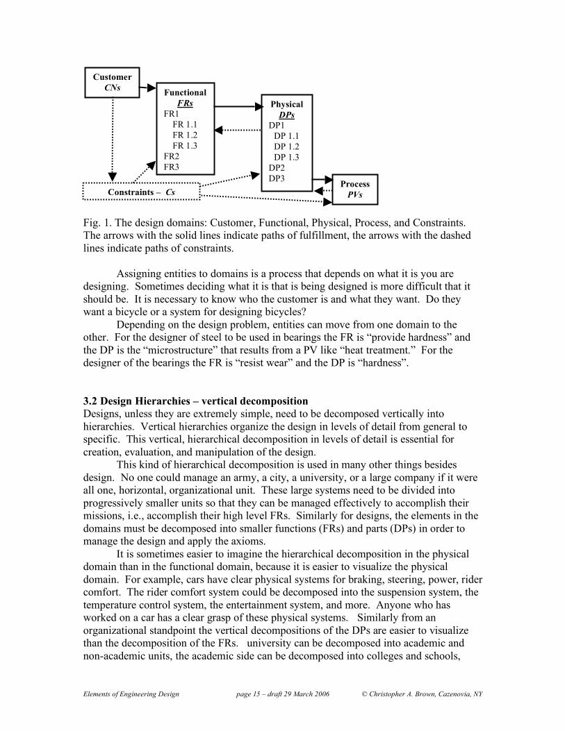
There is a chain of fulfillment that runs from the Customer Domain to the Functional Domain, and then from that to the Physical Domain, and then to the Process Domain (Fig 1).
The Constraint Domain is not in the fulfillment loop. The elements of the Constraint Domain are Cs. Cs can always fit into the category of things that must be avoided rather than fulfilled, e.g., “don’t use flammable materials,” “don’t use processes that pollute.” An important difference between a C and a FR is that an FR requires a DP. Another important difference is that while each FRs should be independent of all of the other FRs, a C can influence all the FRs and DPs, e.g., weight and cost limitations.
Selection of upper level DPs put constraints on lower level FRs. For example, if it is decided that a braking system should be electronic, so an upper level DP would be “Electronic braking system”, then lower level FRs would refer to supplying the needs of an electronic system, e.g., “supply electric power,” as opposed to a hydraulic system where the lower lever FR might be “supply hydraulic pressure.”
Elements of Engineering Design page 15 – draft 29 March 2006 © Christopher A. Brown, Cazenovia, NY
Fig. 1. The design domains: Customer, Functional, Physical, Process, and Constraints. The arrows with the solid lines indicate paths of fulfillment, the arrows with the dashed lines indicate paths of constraints.
Assigning entities to domains is a process that depends on what it is you are designing. Sometimes deciding what it is that is being designed is more difficult that it should be. It is necessary to know who the customer is and what they want. Do they want a bicycle or a system for designing bicycles?
Depending on the design problem, entities can move from one domain to the other. For the designer of steel to be used in bearings the FR is “provide hardness” and the DP is the “microstructure” that results from a PV like “heat treatment.” For the designer of the bearings the FR is “resist wear” and the DP is “hardness”. 3.2 Design Hierarchies – vertical decomposition Designs, unless they are extremely simple, need to be decomposed vertically into hierarchies. Vertical hierarchies organize the design in levels of detail from general to specific. This vertical, hierarchical decomposition in levels of detail is essential for creation, evaluation, and manipulation of the design.
This kind of hierarchical decomposition is used in many other things besides design. No one could manage an army, a city, a university, or a large company if it were all one, horizontal, organizational unit. These large systems need to be divided into progressively smaller units so that they can be managed effectively to accomplish their missions, i.e., accomplish their high level FRs. Similarly for designs, the elements in the domains must be decomposed into smaller functions (FRs) and parts (DPs) in order to manage the design and apply the axioms. It is sometimes easier to imagine the hierarchical decomposition in the physical domain than in the functional domain, because it is easier to visualize the physical domain. For example, cars have clear physical systems for braking, steering, power, rider comfort. The rider comfort system could be decomposed into the suspension system, the temperature control system, the entertainment system, and more. Anyone who has worked on a car has a clear grasp of these physical systems. Similarly from an organizational standpoint the vertical decompositions of the DPs are easier to visualize than the decomposition of the FRs. university can be decomposed into academic and non-academic units, the academic side can be decomposed into colleges and schools,
Functional FRs
FR1 FR 1.1 FR 1.2 FR 1.3
FR2 FR3
Physical DPs
DP1 DP 1.1 DP 1.2 DP 1.3
DP2 DP3
Customer CNs
Process PVs Constraints – Cs
Elements of Engineering Design page 16 – draft 29 March 2006 © Christopher A. Brown, Cazenovia, NY
which can be decomposed into departments, which can be decomposed into programs. Sometimes it is more difficult to imagine the decomposition in the functional domain. But because the design must be functionally based, the functional domain is where the decomposition must originate.
There may be different themes along which a design can be decomposed. The themes that are selected for decomposition will influence the outcome, as well as the ability to apply the axioms. The themes for the decompositions must be based on the desired functions that the design should accomplish. The functions should be customer based. Keeping the decomposition based on the functions helps to insure that the design stays focused on the functions and will satisfy the customer. It also helps to insure that the form will follow the function, i.e., the DPs follow the FRs.
The decomposition structure goes from general at the top to specific at the bottom. The decomposition continues into finer and finer levels of detail until it is clear what the lower levels would be. In other words, follow the decomposition until the solution to the rest of the design detail is obvious. As is discussed in the section that follows on process the FRs are decomposed first, then DPs are selected to satisfy them.
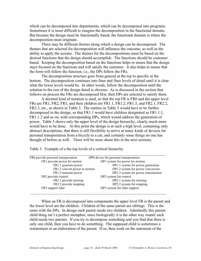
A decimal kind of notation is used, so that the top FR is FR0 and the upper level FRs are FR1, FR2, FR3, and their children are FR1.1, FR1.2, FR1.3, and FR2.1, FR2.2, FR2.3, etc., as shown in Table 3. The entities in Table 3 would have to be further decomposed in the design, so that FR1.1 would have children designated as FR1.1.1, FR1.1.2 and so on, with corresponding DPs, which would address the generation of power. Table 3 shows only the upper level of the design hierarchy, clearly much more would have to be done. At this point the design is at such a high level, containing only abstract descriptions, that there is still flexibility to arrive at many kinds of devices for personal transportation from a bicycle to a car, and certainly some things no one has thought of before as well. There will be more about this in the next sections.
Table 3. Example of a the top levels of a vertical hierarchy _____________________________________________________________________ FR0 provide personal transportation DP0 device for personal transportation
FR1 provide power for motion DP1 system for power for motion FR1.1 generate power DP1.1 system for power generation FR1.2 convert power to motion DP1.2 system for power conversion FR1.3 transmit power DP1.3 system for power transmission FR2 provide control DP2 system for control FR2.1 provide steering DP2.1 system for steering FR2.2 provide stopping DP2.2 system for stopping FR3 support rider DP3 system for rider support
_____________________________________________________________________ When an FR is decomposed into components the upper level FR is the parent and
the lower level are the children. Children of the same parent are siblings. This is the same with the DPs. In design each parent needs two children. Admittedly this parent-child thing isn’t a perfect metaphor, since biologically it is the other way round: each child needs two parents. If you try to decompose something and you find that there is only one child, then you have to do something. The supposed child is sometimes a restatement or an elaboration of the parent. If so, then work on the statement of the

Elements of Engineering Design page 17 – draft 29 March 2006 © Christopher A. Brown, Cazenovia, NY
parent FR. If you are convinced the parent FR needs to be decomposed, then you must find another child, i.e., a sibling for the otherwise single child. A parent and its children are called a branch. In table 3 FR1 and its children could be called the power branch, while FR2 and its children could be called the control branch, because power and control are the respective objectives of each branch. The branches would be decomposed further, to the leaf level, or the nitty-gritty of the design. At the leaf level it is obvious what each DP is and probably how each DP is to be obtained or created. 3.2.1 Collectively Exhaustive and Mutually Exclusive (CEME)
This is a concept that is important and useful enough that it deserves special attention at this point. This concept also can be applied beneficially in many kinds of situations beyond axiomatic design.
Decompositions at each level should be Collectively Exhaustive and Mutually Exclusive (CEME). Collectively exhaustive so that everything that should be included is included – making sure that nothing is left out. Mutually exclusive so that each thing is separate or distinct and there is no overlap – avoiding coupling that can lead unintended consequences.
CEME applies to decompositions of many other things besides design. Anyone that has done free-body diagrams in high school physics has used the principle of CEME. Decomposing a force into its x, y, and z components is CEME. It also should be a useful decomposition, in that it makes the problem easier to understand and solve. Anyone who has done this much has probably noted that some coordinate system orientations and locations are better than others for solving problems. Selecting the right theme for the decomposition is a little like selecting the right orientation and location for the coordinate system in setting up a solution in Newtonian mechanics. 4. Processes
The objective of this section is to explain the processes for creating the structures necessary to systematically apply the axioms to a design. The first parts of the process are to decide what it is that is being designed, define the domains appropriately and then to perform a functionally based decomposition. The second part is to integrate the physical parts into a full design. In the traditional kind of engineering design the outcome is a drawing. This traditional outcome is not meant to be restrictive, as an engineering drawing can be used as a metaphor for other kinds of designs or plans.
The result of the design process should not only provide sufficient information so that the design can be completely communicated and implemented. In axiomatic design every design feature should be traceable to a function. As much as is practical the traceability can be indicated on the drawing, often by referencing the position in the hierarchy, e.g., DP1.2. The reference to the location in the structure should supply the rationale of the design. In the structure the design decisions should be traceable in the final design product. This traceability of rationale may require notes or documentation in the design that are written during the decomposition and integration processes.
The process should result in a structure of the design, through documented decompositions, such that the impact of modifications to the design on the fulfillment of

Elements of Engineering Design page 18 – draft 29 March 2006 © Christopher A. Brown, Cazenovia, NY
the axioms can be easily understood. In this way the controllability and robustness of the design can be maintained during design changes and unintended consequences avoided.
The final product of the axiomatic design process should somehow show the design, as in drawings, and indicate which FRs are fulfilled by which DPs. There should be a clear indication of the design hierarchy to show the decomposition. Design matrices at all levels should be included. For engineering designs the final product typically would be blueprints or some kind of engineering drawings with indications of the FRs and DPs. These engineering drawings indicate results of the final step of the engineering design process, physical integration of the DPs.The examples that are used in this and other works on design are largely from exiting designs. This is a serious shortcoming. While it is interesting to deconstruct existing designs, the real work of design is to create something new. This requires a process of creation. 4.1 Zigzagging Decomposition
There are several useful novel outcomes from this zigzagging process. The process of zigzagging decomposition creates the structures that are necessary for applying the axioms.
The upper level decompositions are frequently ignored in traditional design processes. When the process focuses too quickly on details, then the design decisions are not as traceable and the rationale may not be as clear and the impact of changes on the high level functions may not be as obvious, as when the upper levels of the hierarchy are adequately developed.
Another valuable outcome is the verification of compliance with the axioms, which is unique to axiomatic design.
The ultimate outcome of the zigzagging decomposition is the list of the physical components and the functions they satisfy. These lists are compliant with the axioms. They are arranged systematically in a hierarchy so that the design decisions are traceable and their rationale is clear. What also should be clear is the impact of changes, which can be traced systematically through the hierarchies, verifying the compliance of the changes with the axioms.
Zigzagging refers to the process of defining the FRs for the functional decomposition on one level, then selecting DPs to satisfy these FRs, then going back to define the FRs at the next level on each of the branches. This process continues down each of the braches until the solution is obvious. The zigzagging process is shown graphically in Fig 2.
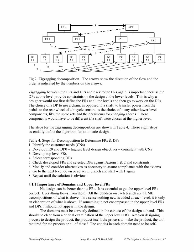
Elements of Engineering Design page 19 – draft 29 March 2006 © Christopher A. Brown, Cazenovia, NY
Fig 2. Zigzagging decomposition. The arrows show the direction of the flow and the order is indicated by the numbers on the arrows. Zigzagging between the FRs and DPs and back to the FRs again is important because the DPs at one level provide constraints on the design at the lower levels. This is why a designer would not first define the FRs at all the levels and then go to work on the DPs. The choice of a DP to use a chain, as opposed to a shaft, to transfer power from the pedals to the rear wheel of a bicycle constrains the choice of many other lower level components, like the sprockets and the derailleurs for changing speeds. These components would have to be different if a shaft were chosen at the higher level. The steps for the zigzagging decomposition are shown in Table 4. These eight steps essentially define the algorithm for axiomatic design. Table 4. Steps for Decomposition to Determine FRs & DPs 1. Identify the customer needs (CNs) 2. Develop FR0 and DP0 – highest level design objectives – consistent with CNs 3. Develop top level FRs 4. Select corresponding DPs 5. Check developed FRs and selected DPs against Axiom 1 & 2 and constraints 6. Modify and consider alternatives as necessary to assure compliance with the axioms 7. Go to the next level down or adjacent branch and start with 1 again 8. Repeat until the solution is obvious 4.1.1 Importance of Domains and Upper level FRs
No design can be better than its FRs. It is essential to get the upper level FRs correct. Everything flows from them. All the children on each branch are CEME decompositions of what is above. In a sense nothing new is added at each level, it is only an elaboration of what is above. If something in not encompassed in the upper level FRs and DPs, it should not appear in the design.
The domains must be correctly defined in the context of the design at hand. This should be clear from a critical examination of the upper level FRs. Are you designing process to design the product, the product itself, the process to make the product, the tool required for the process or all of these? The entities in each domain need to be self-
FR 1 FR 2 DP 1 DP 2
FR 1.1
FR 1.2
FR 1.3
FR 2.1
FR 2.2
DP 1.1
DP1.2
DP1.3
FR 0 DP 0
DP 2.1
DP 2.2
1
2
3 4
5 6
7 8 9…
Elements of Engineering Design page 20 – draft 29 March 2006 © Christopher A. Brown, Cazenovia, NY
consistent. Use extra design processes if you need to. You may need to zigzag between the different designs, e.g., from product design, to process design, to tool design, as appropriate. Recognize when points come up, which are legitimate parts of the current design process and which need to be spun off, to a separate but maybe associated process. The ME part of the CEME decomposition is essential for avoiding coupling of the first kind, between FRs at the same level. Naturally the parent FR is coupled with each child FRs, but the children must be independent of one another to satisfy Axiom One. Design teams new to the axiomatic design process, but committed to it, can spend hours, or even days for large design projects, working on the upper level FRs and DPs. The definition of the upper levels goes well if someone presents a draft evaluates it with the rest of the team, critically, word by word. Egos should be left out of this process. It is useful to have a computer projector and appropriate software (Acclaro is good) for axiomatic design. At the end of these hours or days there may not even be any conceptual drawings to show for the effort, only some upper level FRs and maybe some generic DPs. If these upper levels are right, so that the design team all buys into them, then the investment in getting them right will pay off in time and quality of the design as the process moves forward.
Only when the importance of the upper level FRs and corresponding DPs are realized can the value of getting them right be appreciated. Getting them right takes time. No design can be better than its FRs.
If you are working on the design by yourself, even a small design project, like planning a vacation, you will benefit from writing down the upper level FRs and DPs and developing the design matrices discussed below. The definition of the upper level FRs is good when they the minimum list of independent functions that satisfy the customer needs completely. In other words, in the context of the CNs the FRs are minimum list that is CEME.
The one thing that takes time and is difficult to control, is the process of understanding the customer needs to provide the proper context for developing the upper level FRs. This is because rarely does the customer understand axiomatic design so the needs expressed are a mixture of FRs, DPs, PVs, and Cs at all levels. The CNs as stated by the customer are usually not CEME. They are usually redundant, maybe contradictory, and overlapping. The definitions of the words in the CNs are usually uncertain. Getting the FRs right has to involve interaction with the customers. The better the customer understands axiomatic design, the faster the designer and the customer will converge on the right FRs. 4.1.2 Using Generic DPs at the upper levels
The upper level DPs can be generic, especially at the beginning. This helps speed the process of further decomposing the FRs. Generic DPs are like those listed in Table 3. They are systems and devices. They are still flexible, in that they have not been narrowed to thermal, mechanical, electric, pneumatic, or hydraulic. The detail can come on further decomposition. Several competing DPs can be considered in parallel. 4.1.3 Checks at each level
At each level in the decomposition, as the DPs are being considered, before zigzagging back to the next level down on the FRs three actions have to be made. As

Elements of Engineering Design page 21 – draft 29 March 2006 © Christopher A. Brown, Cazenovia, NY
listed in Table 5. First be sure that no constraints are violated, then check for coupling for compliance with axiom one, and then if there are still choices left select the DP with the highest probability of fulfilling the FR. Table 5. Checks at each level order Description Tool metric 1 Compliance with constraints Checklist Violation 2 Compliance with axiom 1 Matrix Coupling 3 Selection from axiom 2 Equation Probability of
success The checklist for verifying the compliance with the constraints can be straightforward on some items, like don’t release certain elements in to the environment when you are designing a manufacturing process. Some are more difficult, like cost or weight when you are designing a large system with many components, then it is difficult to say is one component has violated the constraint. Then it might help to work out some kind budgeting negotiation, so that different branches can be granted some portion of the weight or cost. 4.1.3.1 Checking for axiom one This is probably the most valuable part of axiomatic design, verifying compliance with axiom one, the independence axiom. The procedure is to check for coupling using matrices. In this example the matrix is set up to look for coupling of the second kind, between DPs and FRs.
Ideally each DP only influences the FR it is selected to fulfill. However this is not always the case. In order to visualize the DP-FR influences a design matrix is used. The FRs listed down the left side and the DPs listed across the top and influences or lack of are recorded in the matrix elements indicated by Xs and 0s respectively as shown in Table 6. Table 6. Uncoupled basic Design Matrix - fully independent DP1 DP2 DP3 FR1 X 0 0 FR2 0 X 0 FR3 0 0 X
The fully independent, uncoupled design matrix, as shown in Table 5 is the optimum. The Xs indicate interactions of the DPs on FRs. In this example each DP influences only one FR, the one it was selected to influence. The matrix is called diagonal, because the Xs are on all of the diagonal elements and all the off diagonal elements are zero. While the example shows only three FRs and DPs this kind of matrix could be used for any number of FRs and DPs.
If there off-diagonal terms that are non-zero (Xs) then there is a risk that the design will suffer from unintended consequences, poor control and undesirable iterations. These are the design problems that result from non-compliance with axiom one. To a

Elements of Engineering Design page 22 – draft 29 March 2006 © Christopher A. Brown, Cazenovia, NY
certain extent some non-zero, off-diagonal terms can be accommodated. There is more on this below.
The matrix elements above the diagonal are referred to as the upper triangle and the matrix elements below are referred to as the lower triangle. If either of these triangles is filled with X’s, then the matrix is referred to as upper triangular or lower triangular, depending on which triangle has the Xs. If they are not all filed in the upper or lower triangle, then it can be referred to as a partial triangular matrix.
Note that the number of DPs must be the same as the number of FRs. That means that the design matrix must be square. If the design matrix is not square, then the design is either coupled or redundant.
The design matrix is not necessarily symmetric. In other words, an X in the 1,3 position (first row, third column) means that DP3 influences FR1. In order for this to be a symmetric matrix then there would also have to be an X in the 3,1 position (third row, first column), which indicates an influence by DP1 on FR3, but this is not necessarily the case. Just because DP3 influences FR1 does not mean that DP1 will influence FR3. The form of the matrix depends on the choices of the FRs and DPs.
If we look at the design of a personal transportation device shown in Table 3, the design matrix in Table 6 might apply. However the level of the hierarchy is so high in Table 3 it is difficult to tell what is going on in terms of interactions. The use of generic DPs makes the design sufficiently abstract at this stage, that almost any combination of interactions in the design matrix might be imagined. Consider making the generic design started in Table 3 slightly more specific. Selecting the rider’s legs for the power moves the design towards a conventional bicycle, as shown in Table 7. Table 7 design of a bicycle – higher levels ______________________________________________________________________________________ FR0 provide personal transportation DP0 device for personal transportation
FR1 provide power for motion DP1 system for power for motion FR1.1 generate power DP1.1 rider’s legs FR1.2 convert power to motion DP1.2 pedal-crank system FR1.3 transmit power DP1.3 chain-sprocket-rear wheel system FR2 provide control DP2 system for control FR2.1 provide steering DP2.1 front headset system FR2.2 provide stopping DP2.2 braking system FR3 support rider DP3 system for rider support FR3.1 support upper body DP3.1 front frame vertical loading system FR3.2 support lower body DP3.1 rear frame vertical loading system
______________________________________________________________________________________ With the information in Table 7 it is possible to fill in the design matrix more completely. Since the legs, which need to be supported, are being used for power, the provide power branch is going to interact with the support. We could make a similar argument for the upper body, which needs to be supported and helps to provide steering. At first glance the bicycle looks like highly coupled; actually it is a good example of physical integration while maintaining functional independence. Table 8. Quasi-coupled or decoupled Design Matrix - managed dependence DP1 DP2 DP3

Elements of Engineering Design page 23 – draft 29 March 2006 © Christopher A. Brown, Cazenovia, NY
FR1 X 0 0 FR2 0 X 0 FR3 X X X
Fig. 3 shows the expanded matrix with the interactions of the next level down. At this level of complexity it is useful to use software. Acclaro (axiomaticdesign.com) is written for facilitating axiomatic design. Fig. 3 and Table 8 show the same interactions at the highest level. (Note that Fig. 3 shows the zero level, which could be considered to be a higher level, but will not be considered here.) Fig. 3 allows us to see where in the lower the interaction comes from that couples FR3 to DP1 and to DP2.
The influence of DP1 on FR3 comes from the interaction of the riders legs, being used for power (DP1.1) impacting the support for the lower body (FR3.2). If the legs are going to supply power, then they must be able to move, as power is a product of the force and the speed, which implies movement. If the legs are going to be able to move then the support for the lower body must take this movement into consideration, hence the design of the often uncomfortable, conventional bicycle seat.
Fig. 3 A screen shot from Acclaro modified to emphasize the inheritance of
coupling from children to parents. (note to self: re-do this figure highlight the 0 level and cover the lines between the boxes – use the block mode for showing the matrix)
The influence of DP2 on FR3 comes from the interaction of the control system
with the support of the upper body. Since the upper body is supported on the handlebars (found in a further decomposition of DP 2.1), and the handlebars are also used for control, then the support for the upper body is influenced by the design of the control system.

Elements of Engineering Design page 24 – draft 29 March 2006 © Christopher A. Brown, Cazenovia, NY
` Notice that the coupling is inherited by the parents from the children. The children collectively must be a collectively exhaustive, i.e., complete, decomposition of the parent, and nothing more than that. For the parents not to inherit coupling from the children implies that the children contain something that is not in the parent, and hence are not a good decomposition of the parent. The children cannot contain anything more than what is in the parent. Therefore, if the children DPs are influencing children FRs, i.e., coupled with other children, then the parents of these children are also coupled. The upper level design matrix then inherits the Xs, which indicate the coupling, from the lower levels. Assigning coupling during the decomposition can be speculative or a kind of act of faith in how the children will turn out. It can also be viewed as commitment of the designer to trying to make the coupling of the children turn out a certain way. The design matrix should be constructed and analyzed at each level in each branch of the decomposition. Since the children at the end of the branch, i.e., leaf level children, are not known until the decomposition reaches that level, and the upper levels inherit coupling from the lower, there can be some uncertainty about coupling at the upper levels earlier in the process. In a new design the diagonal elements should all be Xs, if not, then another DP should be selected or developed that actually fulfills the FR it is intended to fulfill, and an X appears on the diagonal. The off-diagonal terms ideally should all be zero, indicating no interaction, but it is not always possible through the lower levels of the decomposition.
If at a lower level off-diagonal coupling is encountered, then it has to propagate, i.e., be inherited, all the way up indicating undesirable FR-DP coupling, until it merges with a diagonal at a higher level. The design matrices at the higher levels would therefore need to be adjusted, until it eventually merges to a diagonal. Note that at the zero, i.e., highest, level designs, there is one FR and one DP so all coupling at the lower levels has merged into the diagonal.
In the design matrix in Table 8 the upper three elements, upper triangle, are all shown as zero. Similarly, at the lower levels, shown in Fig. 3 the off-diagonal zeros are maintained. There are designs that are easily imagined where the Xs could be introduced into the upper triangle in Fig. 3. Imagine a lovely comfortable seat, with a horizontal portion that supports the thighs and the butt more fully against gravity. Imagine how it would work on a conventional bicycle. You would not be able to pedal because the horizontal thigh-butt support portion would get in the way. Therefore keeping the Xs out of some of the upper triangle are a commitment to keeping the seat out of the way of the legs at the lower levels of the decomposition.
FRs at each level normally should be decomposed in a environment that is neutral with respect to the DPs that will eventually satisfy them, i.e., a solution neutral environment. The problem with using the design of a well known existing device, like a bicycle, as an example in learning the design process is that there are strong pre-conceptions of what the DPs should be. In this design exercise we have been working with a pre-conceived solution of a conventional bicycle. Clearly this is not a solution neutral environment because everyone has knows what a bicycle looks like and it is hard to ignore that knowledge when formulating the FRs at each level. Acknowledging this difficulty, trying to overcome preconceived solutions in design can at least help to

Elements of Engineering Design page 25 – draft 29 March 2006 © Christopher A. Brown, Cazenovia, NY
improve the learning exercise and can help to understand the impact of preconceived solutions on inhibiting the formulation of alternative DPs.
In this process we are imagining that there is interference between supplying power with the legs and supporting the lower part of the body, because we are imagining that the pedals are positioned vertically somewhere below the hips. There may be some good reasons to do this, such as to improve control during leaning and to get the head high enough to see above cars and apply the body weight directly to the pedals. Another solution would be to imagine that the legs could be more horizontal in a recumbent configuration.
For this exercise we could imagine that there is a constraint, stating that the solution should look something close to an existing bicycle. In reality there might be good reasons for this as well, such as marketability.
In this process we have chosen to leave Xs out of the DP columns relating to the Support System, where they would interact with FRs to Provide Control and Power. That means we have made a commitment to select the support systems so they do not interfere with the control and power systems in the lower levels of the design.
In this design example supplying the power is more important than comfort in rider support system. This relative importance of supplying power over providing comfort in the support system is manifested in the design matrix. The pattern of Xs and 0s shows in the off-diagonal locations how the design is to proceed. In Fig. 3 coupling is foreseen between DP1 the power system and FR3 for supporting the rider. Coupling is not foreseen between the DPs for rider support and the FRs for supplying power. So there is intent that is evident in the design matrix to keep the rider support system out of the way of the power supply. It might have been done the other way around, with the intent to design a comfortable support system first and work the power system around it. In this case the matrix would be upper triangular as opposed to lower. Emphasis on the rider support system over the power supply system might lead to a recumbent configuration as opposed to conventional.
There are two other possibilities. One is that at this level, where the DPs are still generic, the matrix is left diagonal and the designer tries to find specific solutions that leave the design uncoupled, i.e., diagonal. This would be the best solution; however, filling in Os in all the off-diagonal locations at this level is no guarantee that the specific solutions to keep the design uncoupled at the lower levels will be found. The other possibility is to have a coupled design with Xs on both sides of the diagonal, and no way of rearranging the matrix to place them all in one triangle or the other.
The degree of satisfaction of axiom one is indicated by the number and placement of the off diagonal Xs. As stated above diagonal is best, triangular is acceptable and anything else should send the designer looking for other DPs or restating the FRs to find a better solution. There are ways of quantitatively evaluating the design matrix to quantify the coupling, although the quantitative relation between the FRs and DPs must be known and reducible to a coefficient (Suh 1990).
The Xs are place holders for the actual relations between FRs and DPs. Many times that is all that is needed to proceed with the design. These relations that the Xs are holding the places for might be expressed as an equation, a table or a graph. With the relation expressed as a graph, then the FR could be on the vertical axis and the DP on the

Elements of Engineering Design page 26 – draft 29 March 2006 © Christopher A. Brown, Cazenovia, NY
horizontal axis, as discussed below in section 4.1.2. There is more about this in later chapters. 4.1.3.2 Checking for axiom two
Axiom two states that of all the designs that satisfy axiom one equally, the best is the one with the least information. In this context information is inversely related to the probability of success, i.e., the greater the probability of success the smaller the information content. The information can be calculated quantitatively as shown below in equation [1].
During the design process the task is to choose between alternative DPs. This means that one must evaluate and compare the probability of success of two design parameters, or two sets of design parameters – the probabilities that they can fulfill the functional requirements that they are selected to fulfill. This task needs to be applied to competing designs that satisfy axiom one, i.e., pass step two in Table 5 equally.
In applying axiom two, we need to realize that things that can go wrong it will go wrong some percentage of the time. Applying axiom two removes the opportunity for Murphy’s law to be applied. During assembly if a component can be inserted upside down, it will be. If there are two different sizes of fasteners with similar appearance that are needed and supplied for assembling something, then someone will get them mixed up. What is commonly called “idiot proofing” is consistent with the application of axiom two.
To get a design that is compliant with axiom two there need to be safeguards against actions that will lead to failure. This realization leads to the consideration of the information content in triangular matrices as opposed to diagonal. Designs that have triangular design matrices inherently have less of a probability of success as compared with diagonal matrices. This is because, when there are Xs in the off-diagonal locations in the matrix, a certain order of adjustment of the DPs is required, in order to fulfill the FRs and avoid iteration. That order of adjustment increases the information content, as long as there is a probability less than one that the order of adjustment will be missed.
The procedure for the application of axiom two is to assign each DP in the branch and level being considered a probability of success of satisfying the corresponding FR. Probabilities must be between zero and one, where zero means that there is no chance of success and one means that there is no chance of failure. At this point the best design may already be obvious.
If the best design is not already obvious, then one approach is to multiply all the probabilities to calculate an overall probability of success of each design being considered. The result will be between zero and one. A design where all the probabilities are one has the least information content. A design where the probability of success is zero has an information content that is infinitely large.
Another approach is to apply equation one and calculate the information content. I = log(1/p) [1]
Equation one states that the information content, I, is equal to the log of one divided by the probability of success, p. As discussed above the probability, p, must be greater than or equal to zero and less than or equal to one. Therefore, since the log of one is zero, then there is a perfect probability of success the information content is zero. When there
Elements of Engineering Design page 27 – draft 29 March 2006 © Christopher A. Brown, Cazenovia, NY
is no probability of success and p equals zero then the term in the parentheses in equation one goes to infinity, as does the information content. The units on the information content depend on the base used for taking the logarithm in equation one. If log base two is used then the units are bits, if the natural log is used then the units are nats. Any log base can be used, as long as it is consistent, and you don’t add different kinds of units without converting them, just as you would not add pounds and kilograms. For each DP a probability of success can be determined, or estimated, and the information content can be calculated. The total information content for a branch and level of design is the sum of all the information contents. If there are conditional probabilities then the process is more involved, and this will be discussed later. For now the design decision can be made at each level based on the total information content.
The parents inherit the information content from the children, so that information contents at the higher levels will have to be revised, just as the design matrix for determining compliance with axiom one must be, based on the results of the details of the design, as the design progresses.
If you prefer multiplying probabilities to determine the overall success, then there is no reason to use equation one. Selecting the design that has the greatest probability of success is an equivalent statement of axiom two. In general it may be more convenient to add information contents than to multiply probabilities. And it may be easier to minimize something that goes to zero, as opposed to maximizing something that goes to one. 4.2 Physical Integration This is the final step of the design process. This is the step where the components, resulting from the decomposition and application of the axioms are somehow integrated into one product, and generally this will be a physical integration. During the physical integration the compliance with the axioms needs to be maintained. The physical integration often provides opportunities to reduce the information content, and often carries the risk of introducing the kind of coupling earlier referred to as integrational coupling. At the completion of this physical integration step the design should be complete.
Physical integration is the process of combining all the components, the DPs, into one entity. Physical integration should be viewed broadly so that it can be applied to non-physical designs. Physical integration does not mean that all the components must be physical or connected physically.
In general everything that can be physically integrated should be, provided that the axioms are not violated as a result of the physical integration.
Coupling of the second (FR-DP) and third (DP-DP) kinds need to be avoided during physical integration.
Coupling of the second kind should have been addressed in the decomposition phase. All of the FR-DP coupling that could be avoided should have been avoided in the decomposition phase. The objective in the integration phase in regard to FR-DP coupling is not to exacerbate it – new FR-DP coupling should be avoided as well as increasing the degree of undesired FR-DP coupling that already exists.
DP-DP coupling can be investigated with a physical integration matrix, where the DPs are mapped against the DPs. The diagonal on this matrix can be ignored as a DP
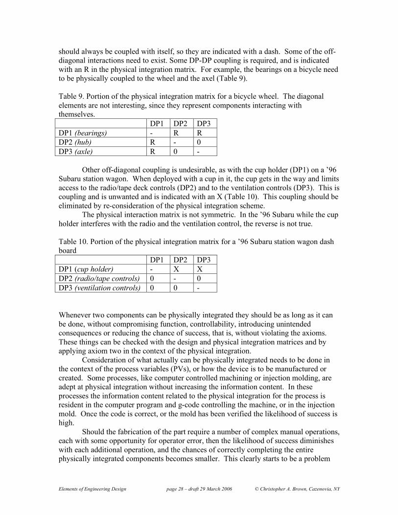
Elements of Engineering Design page 28 – draft 29 March 2006 © Christopher A. Brown, Cazenovia, NY
should always be coupled with itself, so they are indicated with a dash. Some of the off-diagonal interactions need to exist. Some DP-DP coupling is required, and is indicated with an R in the physical integration matrix. For example, the bearings on a bicycle need to be physically coupled to the wheel and the axel (Table 9). Table 9. Portion of the physical integration matrix for a bicycle wheel. The diagonal elements are not interesting, since they represent components interacting with themselves. DP1 DP2 DP3 DP1 (bearings) - R R DP2 (hub) R - 0 DP3 (axle) R 0 -
Other off-diagonal coupling is undesirable, as with the cup holder (DP1) on a ’96 Subaru station wagon. When deployed with a cup in it, the cup gets in the way and limits access to the radio/tape deck controls (DP2) and to the ventilation controls (DP3). This is coupling and is unwanted and is indicated with an X (Table 10). This coupling should be eliminated by re-consideration of the physical integration scheme.
The physical interaction matrix is not symmetric. In the ’96 Subaru while the cup holder interferes with the radio and the ventilation control, the reverse is not true. Table 10. Portion of the physical integration matrix for a ’96 Subaru station wagon dash board DP1 DP2 DP3 DP1 (cup holder) - X X DP2 (radio/tape controls) 0 - 0 DP3 (ventilation controls) 0 0 -
Whenever two components can be physically integrated they should be as long as it can be done, without compromising function, controllability, introducing unintended consequences or reducing the chance of success, that is, without violating the axioms. These things can be checked with the design and physical integration matrices and by applying axiom two in the context of the physical integration.
Consideration of what actually can be physically integrated needs to be done in the context of the process variables (PVs), or how the device is to be manufactured or created. Some processes, like computer controlled machining or injection molding, are adept at physical integration without increasing the information content. In these processes the information content related to the physical integration for the process is resident in the computer program and g-code controlling the machine, or in the injection mold. Once the code is correct, or the mold has been verified the likelihood of success is high.
Should the fabrication of the part require a number of complex manual operations, each with some opportunity for operator error, then the likelihood of success diminishes with each additional operation, and the chances of correctly completing the entire physically integrated components becomes smaller. This clearly starts to be a problem

Elements of Engineering Design page 29 – draft 29 March 2006 © Christopher A. Brown, Cazenovia, NY
with axiom two, information. In these cases it may be advantageous to manufacture the part in such a way that an error on one component does not adversely influence another component. The component with the error can be re-tried, limiting the adverse effects of the error to the component in question. 5. Concluding remarks for Chapter one. Chapter one contains all that is needed to get started with axiomatic design. You should start using it. The value is developed in the application. You can only get benefit from it, and learn to apply it effectively and efficiently if you practice it through use. You should have the knowledge to use this powerful method. To get started with axiomatic design, begin with section four on processes, the third Primary element. You will refer to the other two primary elements as required for building the structure and following the axioms. As you attempt to apply axiomatic design to larger problems, designs with more that about a dozen FR-DP pairs become unwieldy without some kind of software. Acclaro (www.axiomaticdesign.com) is good. Spreadsheets can be helpful.