Electrospinning of Continuous Nanofiber Bundles and ...€¦ · properties and potential...
23
8 Electrospinning of Continuous Nanofiber Bundles and Twisted Nanofiber Yarns Usman Ali, Yaqiong Zhou, Xungai Wang and Tong Lin Centre for Material and Fibre Innovation, Deakin University, Australia 1. Introduction Spinning is a prehistoric technology in which endless filaments, shorter fibers or twisted fibers are put together to produce yarns that serve as key element to assemble multifarious structural designs for diverse functions. Electrospinning has been regarded as the most effective and versatile technology to produce nanofibers with controlled fiber morphology, dimension and functional components from various polymeric materials (Dersch et al., 2007, Frenot and Chronakis, 2003, Schreuder-Gibson et al., 2002). However, most electrospun fibers are produced in the form of randomly-oriented nonwoven fiber mats (Doshi and Reneker, 1995, Madhavamoorthi, 2005). The relatively low mechanical strength and difficulty in tailoring the fibrous structure have restricted their applications. With the rapid development in nanoscience and nanotechnology, yarns composed of nanofibers may uncover new opportunities for development of well-defined three dimensional nano fibrous architectures. This chapter focuses on recent research and advancement in electrospinning of nanofiber bundles and nanofiber yarns. The preparation, morphology, mechanical properties and potential applications of these fibrous materials are discussed in details. 2. Nanofibers and yarns Nanofibers are defined as one dimensional nanomaterials with diameters less than 1 µm (1000 nm), and an aspect ratio (length/diameter) larger than 100:1. They are also named superfine or ultrathin fibers in some literatures (Supaphol et al., 2005, Alborzi et al.). When the fibers are in the range of 100–1000 nm, they are also referred to as submicron fibers (Bellan et al., 2006, Keun Kwon et al., 2005, Givens et al., 2007). This intrinsic feature offers them drastically increased surface to volume ratio and high aspect ratio. There are several methods to prepare nanofibers, encompassing top-down (melt-blown (Ellison et al., 2007), melt electrospinning (Dalton et al., 2007, Lyons et al., 2004), islands-in-the-sea (Nakata et al., 2007), and electrospinning (Bhardwaj and Kundu)), and bottom-up (interfacial polymerization (Xing et al., 2008), self-assembly (Viney, 2004), and phase separation (Zhao et al.)) approaches. Nanofibers produced from electrospinning have a naturally formed porous structure with excellent pore interconnectivity and the pores are in the range between tens of nanometers to a few micrometers. The open pore structure and high permeability to gas, along with the high surface area make them ideal porous membranes. Compared with other one-dimensional nanostructures (e.g. nanotubes or nano-rods), www.intechopen.com
Transcript of Electrospinning of Continuous Nanofiber Bundles and ...€¦ · properties and potential...

8
Electrospinning of Continuous Nanofiber Bundles and Twisted Nanofiber Yarns
Usman Ali, Yaqiong Zhou, Xungai Wang and Tong Lin Centre for Material and Fibre Innovation, Deakin University,
Australia
1. Introduction
Spinning is a prehistoric technology in which endless filaments, shorter fibers or twisted fibers are put together to produce yarns that serve as key element to assemble multifarious structural designs for diverse functions. Electrospinning has been regarded as the most effective and versatile technology to produce nanofibers with controlled fiber morphology, dimension and functional components from various polymeric materials (Dersch et al., 2007, Frenot and Chronakis, 2003, Schreuder-Gibson et al., 2002). However, most electrospun fibers are produced in the form of randomly-oriented nonwoven fiber mats (Doshi and Reneker, 1995, Madhavamoorthi, 2005). The relatively low mechanical strength and difficulty in tailoring the fibrous structure have restricted their applications. With the rapid development in nanoscience and nanotechnology, yarns composed of nanofibers may uncover new opportunities for development of well-defined three dimensional nano fibrous architectures. This chapter focuses on recent research and advancement in electrospinning of nanofiber bundles and nanofiber yarns. The preparation, morphology, mechanical properties and potential applications of these fibrous materials are discussed in details.
2. Nanofibers and yarns
Nanofibers are defined as one dimensional nanomaterials with diameters less than 1 µm (1000 nm), and an aspect ratio (length/diameter) larger than 100:1. They are also named superfine or ultrathin fibers in some literatures (Supaphol et al., 2005, Alborzi et al.). When the fibers are in the range of 100–1000 nm, they are also referred to as submicron fibers (Bellan et al., 2006, Keun Kwon et al., 2005, Givens et al., 2007). This intrinsic feature offers them drastically increased surface to volume ratio and high aspect ratio. There are several methods to prepare nanofibers, encompassing top-down (melt-blown (Ellison et al., 2007), melt electrospinning (Dalton et al., 2007, Lyons et al., 2004), islands-in-the-sea (Nakata et al., 2007), and electrospinning (Bhardwaj and Kundu)), and bottom-up (interfacial polymerization (Xing et al., 2008), self-assembly (Viney, 2004), and phase separation (Zhao et al.)) approaches. Nanofibers produced from electrospinning have a naturally formed porous structure with excellent pore interconnectivity and the pores are in the range between tens of nanometers to a few micrometers. The open pore structure and high permeability to gas, along with the high surface area make them ideal porous membranes. Compared with other one-dimensional nanostructures (e.g. nanotubes or nano-rods),
www.intechopen.com

Nanofibers – Production, Properties and Functional Applications
154
continuous nanofibers are advantageous in terms of fabrication cost and the possibility of being integrated into other desired assembly in one-step. Ascribed to the high surface area, porous structure, and the ability to adopt functional molecules and nanomaterials (e.g. nanoparticles, nanotubes), nanofiber nonwoven webs have been used in areas as diverse as batteries (Norris et al., 2000), biomedical (Liang et al., 2007, Agarwal et al., 2008, Yoshimoto et al., 2003, Cao et al., 2009, Xu et al., 2004), filtrations (Gibson et al., 2001, F. DOTTI and MAZZUCHETTI*, October 2007), medical prostheses (Buchko et al., 1999, Buchko et al., 2001), sensors (Wang et al., 2002b, Wang et al., 2002a), fuel cells (Shabani et al., Li et al.), nanocomposites (Huang et al., 2003, Chronakis, 2005), and protective clothing (Lee and Obendorf, 2007, Ramakrishna et al., 2006). Electrospun nanofibers are generally collected as nonwoven or randomly arranged structures, due to the “whipping instability” of the electrospinning jet. Early studies on fiber deposition and its assemblies were focused on controlling the fiber alignment. A few typical ways to electrospun-aligned nanofibers are shown in Figure 1. Aligned nanofibers can be collected using a dynamic mechanical collector such as cylindrical drum (Ding et al., 2002, Li and Xia, 2004), wired drum (Katta et al., 2004) or a tapered wheel (Xu et al., 2004) , either grounded or negatively charged (Theron et al., 2001). When the collector rotates at a high surface speed, such as 8 m/s, fibers start to align along the rotating axis. However, it is yet difficult to obtain perfect fiber alignment with this method, because the residual charge accumulation on the deposited fibers interferes with the incoming ones.
Fig. 1. Basic methods for controlling the alignment of electrospun nanofibers. (a) High speed rotating drum collector, b) a tapered wheel, c) stationary gap collector.
(a) (b)
(c)
www.intechopen.com

Electrospinning of Continuous Nanofiber Bundles and Twisted Nanofiber Yarns
155
Since the electrostatic forces dominate the electrospinning process, it is also possible to obtain aligned nanofibers through the manipulation of the electric field. Electric field was manipulated by using two split parallel flat plates (Gap Collector) connected with grounded electrode (Li et al., 2004, Liu and Dzenis, 2008, Dan Li, June 20, 2003, Bazbouz and Stylios, 2008a, Kameoka et al., 2004, Ishii et al., 2008), or a frame-shaped collector (Dersch et al., 2003). The distance between two conductive electrodes is up to centimeters. A high degree of fiber alignment can be achieved with this method, and the produced fibers can be easily transferred to other substrates for device fabrication. However, the fibers thus produced are of limited length and thickness. Yarns can be assembled or interlaced into many fibrous structures by the process of weaving, knitting or embroidery (P. J Denton and Daniels, 2002). Single nanofibers are too fragile and too thin for such processes, and it also requires sophisticated equipment for precise handling of these fibers (Tan et al., 2005). Attempts to produce nanofiber yarns from electrospun nanofibers were reported by Formhals as early as in 1934. In a series of patents (Anton, 1934, Anton, 1938b, Anton, 1944, Anton, 1938a), he described the experimental setups to produce polymer filaments by using electrostatic forces. Most of the early works on electrospinning of nanofiber yarns were actually focused on non-twisted nanofiber bundles. Although twist can be inserted by a post-electrospinning treatment, it is now highly preferred that twists can be added to continuous nanofiber yarns directly from an electrospinning process.
3. Discontinuous nanofiber bundles and twisted yarns
Generally, electrospinning produces random nanofiber mats, if a planar stationary plate is used as a collector. However, by manipulating the electric field or using moving collecting or spinneret systems, one can collect non-continuous nanofiber bundles or twisted yarns rather than mats.
3.1 Short nanofiber bundles
In 2001, Deitzel et al (Deitzel et al., Deitzel et al., 2001) demonstrated the deposition of nanofibers in a more targeted fashion by a series of charged rings in the electrospinning zone, as shown in Table 1A. The charged rings had the same polarity as the surface charge on the jet, which increased the downward force on the jet. This method resulted in nanofiber deposition in a narrow strip (0.6 cm wide) when the target was a rotating drum. The average diameter of fibers was 300 nm. The prepared short bundles of polyethylene oxide were analyzed using wide angle X-ray diffraction (WAXD) technique and some molecular orientation but poor crystalline microstructure was found in the fibers. Theron et al (Theron et al., 2001) described an electrostatic field-assisted assembly technique in combination with the dynamic rotating collector to position and align individual nanofibers. Bundles of nanofibers were collected on a tapered wheel-like disc as shown in Table 1B. The disc was made of aluminum with a diameter of 200 mm, a thickness of 5 mm and a tapered angle of 26.6°. The tapered edge of the wheel collector had a strong converging electric field, thus enabling the jet emerged from the droplet to form an envelope cone at the start and then shrink and form an inverted cone, once it approached the sharp edge. As a result, nanofibers of polyethylene oxide (PEO) with a diameter varying within 100-300 nm would preferentially deposit on the wheel edges, which were assembled in a parallel array due to the rotation of the wheel.
www.intechopen.com

Nanofibers – Production, Properties and Functional Applications
156
Teo and Ramakrishna (Teo and Ramakrishna, 2005) demonstrated the fabrication of
nanofiber bundles by collecting them across two negatively charged steel blades (3 cm
apart) as shown in Table 1C, and then dipping them in water. During electrospinning, the
fibers were preferentially deposited between the blades due to the concentration of
electrostatic charges on the sharp edges. The fibers were first deposited on one blade, and
then stretched to the other with the aid of electrostatic forces acting on the fibers. As a result,
fibers were deposited across the gap. However, “stray” fibers could not be eliminated
during the electrospinning process. A further step of dipping fibers in water was thus
required to cluster the fibers together, by the force of water surface tension. The resulting
fiber bundles had two fixed ends, which were of limited length, but they were free to be
transferred to other substrates, and to be twisted or braided manually.
Year Author Setup Morphology Fiber Bundling/Polymer
A. 2001
Deitzel et al. Jet was stabilized by placing a
series of charged rings in the electrospinning zone and the rings were charged to have the same polarity to the spinneret; PEO
B. 2001
Theron et al. Electric field is concentrated on
the tapered wheel which rotates for fiber alignment. The collector has a limited fiber deposition area; PEO
C. 2005
Teo et al.
Gap collector using sharp blades for concentration of electric field; PCL
Table 1. Short Nanofiber Bundles.
Short nanofiber bundles with parallel orientated short fibers can also be prepared by cutting
an aligned nanofiber membrane into narrow strips. In this case, preparing aligned nanofiber
membranes is the focus. Different fiber alignment techniques have been used, such as using
www.intechopen.com

Electrospinning of Continuous Nanofiber Bundles and Twisted Nanofiber Yarns
157
a rapidly oscillating frame (Fong et al., 2002, Dersch et al., 2003), and a copper comb
collector in needleless electrospinning (Jiri Chvojka and Lukas, 2009).
3.2 Short nanofiber yarns
High-speed rotating drum has been recognized as the easiest way to get highly aligned
nanofibers. Fennessey et al (Fennessey and Farris, 2004) prepared short nanofiber yarns
using aligned PAN nanofiber membranes. The nanofiber membrane was cut into short tows
(approximately 32 cm × 2 m) and then linked together. An electric spinner was used to
insert twist and the action of twist on yarn tensile strength and modulus was studied. They
found that increasing the twist angles led to increased yarn ultimate strength and modulus.
Liu et al (Liu et al., 2008) also used a high speed annual shaped collector to prepare aligned
nanofiber membrane, and the membrane was cut and twisted in a similar way into short
yarns. Later on, PAN nanofibers reinforced by carbon nanotubes (CNTs) were also prepared
into short nanofiber yarn by Farouk et al (Farouk et al., 2009) who used a high speed
rotating drum collector. They found that well dispersed CNTs in the polymer solution for
electrospinning led to high yarn mechanical properties. Recently, Moon et al (Moon and
Farris, 2009) prepared short PAN nanofiber yarns using a similar method for making carbon
nanofiber yarns. They reported that the carbon nanofiber yarns had a tensile strength as
high as 1 GPa.
Researchers have also paid attention to directly getting short twisted nanofiber yarns. For
instance, Dalton et al (Dalton et al., 2005) used two parallel grounded rings to get aligned
nanofibers (Table 2A). Nanofibers were first deposited at the lower part of the rings, which
then proceeded upward to the ring top, aligning across the gap. By rotating one of the rings
the suspended fibers were converted into a multi-filament yarn with a diameter of less than
5 µm and a length of 4 ~ 10 cm. The yarn length was limited by the distance between the
two electrodes. Later on Liu et al (Liu et al., 2007) prepared nanofiber-based composite ropes
of poly(methyl methacrylate) (PMMA)/MWCNT by using a gap collector (Table 2B).
Nanofibers were electrospun vertically downward and bridged between the two electrodes.
By rotating the point electrode, the as-spun PMMA/MWNT nanofibers were converted into
yarns of 30 ~ 40 cm in length and 13 ~ 23 µm in diameter. This method was difficult to spin
yarns longer than 40 cm, as the constant distance between two collectors had to be
maintained so that nanofibers can be continuously deposited.
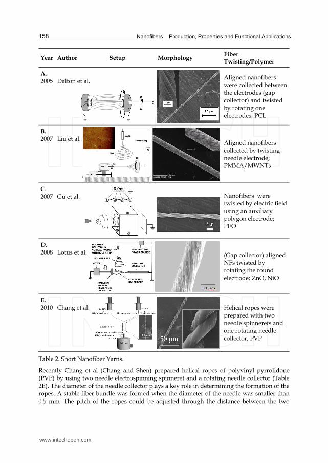
Gu et al (Gu et al., 2007) described a method of directly fabricating single twisted nanofibers by controlling the electric field around an auxiliary electrode (Table 2C). A polygon with several faces was placed in between the needle and the collecting plate. Each face of the polygon was subjected to an applied voltage. By switching the voltage rapidly, a rotated electric field was created, changing the direction of the electrostatic force which led to the twisted nanofibers. Lotus et al (Lotus et al., 2008) also adopted the concept of rotating an electrode in the gap collector to produce twisted nanofiber yarns. The set-up consists of a rotating hollow hemisphere and a non-rotating but translating tapered metal rod. The tapered end of the rod and the edge of the hemisphere are conductive so fibers would preferentially deposit on their edges, and form a conical cone with its apex lying on the rod tip, as shown in Table 2D. by rotating the hollow the hollow hemisphere, and translating the metal rod away, 10cm long zinc oxide and nickel oxide yarns can be fabricated. The yarns are 5~30 µm in diameter and consist of nanofibers 60~100nm in diameter.
www.intechopen.com
Nanofibers – Production, Properties and Functional Applications
158
Year Author Setup Morphology Fiber Twisting/Polymer
A. 2005
Dalton et al.
Aligned nanofibers were collected between the electrodes (gap collector) and twisted by rotating one electrodes; PCL
B. 2007
Liu et al.
Aligned nanofibers collected by twisting needle electrode; PMMA/MWNTs
C. 2007
Gu et al.
Nanofibers were twisted by electric field using an auxiliary polygon electrode; PEO
D. 2008
Lotus et al.
(Gap collector) aligned NFs twisted by rotating the round electrode; ZnO, NiO
E. 2010
Chang et al.
Helical ropes were prepared with two needle spinnerets and one rotating needle collector; PVP
Table 2. Short Nanofiber Yarns.
Recently Chang et al (Chang and Shen) prepared helical ropes of polyvinyl pyrrolidone (PVP) by using two needle electrospinning spinneret and a rotating needle collector (Table 2E). The diameter of the needle collector plays a key role in determining the formation of the ropes. A stable fiber bundle was formed when the diameter of the needle was smaller than 0.5 mm. The pitch of the ropes could be adjusted through the distance between the two
www.intechopen.com

Electrospinning of Continuous Nanofiber Bundles and Twisted Nanofiber Yarns
159
spinnerets. When a needle collector of the diameter greater than 5 mm was used, fibers travelled randomly and deposited as a mat on the collector.
4. Continuous nanofiber bundles
Continuous nanofiber bundles are defined as a group of loosely assembled nanofibers,
which have no twist. The main techniques to get continuous nanofiber bundles are
described in Table 3.
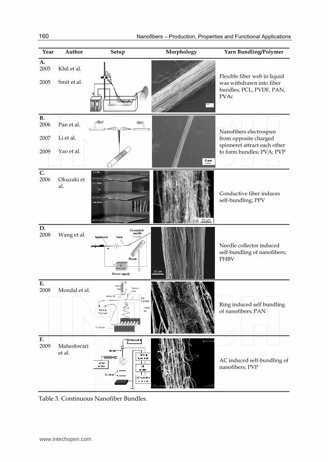
A liquid medium was used separately by Khil et al (Khil et al., 2005) and Smit et al(Smit et
al., 2005)to collect nanofibers and subsequently wind into continuous nanofiber bundles
(Table 3A). Nanofibers initially formed a random web on the liquid surface, which were
drawn and lifted off with a rotating mandrel to form a fiber bundle. Under the action of
liquid surface tension, the bundle was elongated and collapsed into a round cross-section.
By continuously depositing nanofibers into the liquid, while at the same time collecting
them with the winder, a continuous nanofiber bundle was obtained. The fiber bundles could
be drawn at a rate of 0.05 m/s ~ 0.5 m/s. To make the fiber suspend on the liquid surface
could help the collection, and a liquid having a high density or high surface tension was
normally selected as the collecting medium.
To obtain continuous nanofiber bundles, Pan et al (Pan et al., 2006) used a special
electrospinning setup consisting of a pair of spinnerets with opposite polarities and a
rotating shaft collector (Table 3B). In the process, the nanofibers from the two spinnerets
carried opposite charges. They attracted to each other to form a fiber bundle and the fibers
aligned within the bundle. The fiber bundle production rate was dependent on the rotating
speed of the collector, the polymer material used and the fiber diameter produced. The yarn
diameter can be controlled by the number of spinneret pairs. For PVP nanofibers with an
average diameter of 670 nm, the maximum production speed was 14.9 m/s. Later, Li et al
(Li et al., 2008) and Yao et al (Yao et al., 2009) respectively prepared nanocomposite yarns of
poly(L-lactide)(PLLA)/nanotricalium phosphate and PLLA/Zein using this electrospinning
setup. Li et al also studied the effect of electrospinning distance and found that nanofibers
bonded tightly to each other at an electrospinning distance of 20 cm, however longer
electrospinning distance resulted in loosely packed nanofiber bundles.
Okuzaki et al (Okuzaki et al., 2008) observed the formation of poly(p-phenylenevinylene)
(PPV) precursor fiber bundles using just a conventional electrospinning setup (Table 3C).
The spinneret was placed vertically on top of the grounded flat collector. The unusual
bundle formation was explained by the conductive nature of the PPV precursor. The
deposited fibers discharged through polyelectrolyte chains to the grounded target, which
preferred the gravitated deposition so as to decrease the gap between the fibers and the
needle. Centimeter-long nanofiber bundles were formed spontaneously between the
spinneret and the grounded plate within a minute. Subsequent thermal conversion led to
bundles of PPV nanofibers.
In 2008, Wang et al (Wang et al., 2008b) reported a method to self assemble continuous
nanofiber bundles (Table 3D). A grounded needle tip was incorporated into the collecting
system to induce self-bundling of nanofibers. It was observed that the liquid jet was a
straight line initially, and then whipped around until it got close to the tip of the needle
collector, splaying fibers to converge on the needle collector due to the large electrostatic
attraction. By pulling back the bundle and winding it on a grounded rotating collector,
www.intechopen.com
Nanofibers – Production, Properties and Functional Applications
160
Year Author Setup Morphology Yarn Bundling/Polymer
A. 2005 2005
Khil et al. Smit et al.
Flexible fiber web in liquid was withdrawn into fiber bundles; PCL, PVDF, PAN, PVAc
B. 2006 2007 2009
Pan et al. Li et al. Yao et al.
Nanofibers electrospun from opposite charged spinneret attract each other to form bundles; PVA; PVP
C. 2006
Okuzaki et al.
Conductive fiber induces self-bundling; PPV
D. 2008
Wang et al.
Needle collector induced self-bundling of nanofibers; PHBV
E. 2008
Mondal et al.
Ring induced self bundling of nanofibers; PAN
F. 2009
Maheshwari et al.
AC induced self-bundling of nanofibers; PVP
Table 3. Continuous Nanofiber Bundles.
www.intechopen.com

Electrospinning of Continuous Nanofiber Bundles and Twisted Nanofiber Yarns
161
continuous nanofiber bundle was generated, provided that the surface velocity of the rotating drum matched the velocity of the bundle growth. The self-bundling became easier when increasing the conductivity of polymer solution. When the solution conductivity was larger than 400 µS/cm, self-bundling occurred automatically without the induction of a needle collector. Greater fiber alignment was observed with the increase in the solution conductivity. Another approach to prepare electrospun nanofiber yarn was introduced by Mondal et al (Mondal et al., 2008). In their design, the electric field was manipulated by attaching a ring to the spinning nozzle just above the orifice to self-assemble the fibers for yarn formation (Table 3E). To initiate the yarn formation, a glass rod was introduced to attract yarn on the glass rod end. By moving the glass rod away from the spinning zone, a continuous nanofiber yarn was prepared manually. The formation of nanofiber yarn was controlled by temperature, polymer concentration and applied voltage. Maheshwari et al (Maheshwari and Chang, 2009) reported an assembly of multi-stranded nanofiber threads via AC electrospinning (Table 3F). Nanofibers with both positive and negative segments were electrospun because of polarity switching during electrospinning. The fibers experienced an alternation of attractive and repulsive forces, resulting in increased alignment. A visible thread was observed emerging downstream from the spinneret. The thread could be easily deflected away and collected because of the small attraction toward the counter electrode. The authors also showed how the AC voltage and frequency affected the fiber collection. Increasing the frequency suppressed the jet whipping instability, thus giving smaller thread width (thread with lower fiber density), but more beaded fibers. An opposite effect was seen with the increase in the voltage.
5. Continuous nanofiber yarns
A nanofiber yarn can be formed by twisting a thin strand of nanofibers around the axis. The fibers after twisting show a helical configuration. Twist functions to increase the fiber to fiber cohesion and strength of the yarn. In electrospinning research, considerable effort has gone into making continuous twisted nanofiber yarns in recent time. Table 4 summarizes the main techniques that have been developed to electrospin continuous nanofiber yarns.
Year Author Setup Morphology Yarn Twisting/Polymer
A. 2003
Ko et al.
Twisting of nanofibers with a special setup; PAN,PLA
B. 2005
Kim et al.
Manually drawing and twisting nanofibers electrospun from a multi-needle setup; Poly urethane
www.intechopen.com

Nanofibers – Production, Properties and Functional Applications
162
Year Author Setup Morphology Yarn Twisting/Polymer
C. 2006
Kim et al.
Manually drawing and twisting nanofibers electrospun from a needleless electrospinning setup;
D. 2007 2010
Teo et al. Yousef. et al.
Nanofibers twisted due to rotation of liquid water; polymer (Helix angel 19.76°)
E. 2007
Dabirian et al.
Nanofiber stream redirected and twisted by a twist winder; PAN
F. 2007
Bazbouz et al
Nanofibers twisted by rotating the left disk and then taken up by the right disk; Nylon6/MWNT
G. 2008
Lee et al.
Nanofiber web directly twisted by rotating the disk collector; PAI
H. 2009
Dabirian et al.
Nanofibers produced from two oppositely charged spinneret and twisted by using a electronic twister; PAN
www.intechopen.com

Electrospinning of Continuous Nanofiber Bundles and Twisted Nanofiber Yarns
163
Year Author Setup Morphology Yarn Twisting/Polymer
I. 2009
Kim et al.
Single and multi nozzles are arranged along the circumferential direction. Nanofibers are drawn and twisted; Nylon6, Nylon66 (Helix angle up to15°)
J. 2010
Afifi et al.
Fiber web was twisted by an earthed rotating funnel; PLLA
K. 2011
Ali et al.
Nanofiber yarns were
directly produced from an un-earthed fibrous cone formed on a rotating funnel; PVDF-HFP, PCL, PAN, PS (twist angle up to 0 - 61°)
Table 4. Continuous Nanofiber Yarns.
The concept of using nanofiber yarns to make complex fibrous structures for a new
generation of composites was firstly presented by Frank Ko (Ko et al., 2003). Continuous
poly(latic acid) (PLA) and PAN nanofiber yarns filled with carbon nanotubes in the
fibers were produced by applying a yarn twisting and subsequent winding method
(Table 4A). However, no details were presented to explain how the yarns were twisted
and continuously wound, considering in particular that the twisting arrangement
resembles a false twist texturing process rather than one that inserts any real twist into
the yarn.
Kim et al (Kim, 2010a, Kim, 2009a, Kim, 2008b, Kim, 2009b, Kim, 2010b, Kim, 2005) claimed
a series of patents to electrospin continuous filament composed of nanofibers. In one of
these techniques, a multiple needle electrospinning system was used to produce nonwoven
web on a rotating belt which was then stretched and collected on single winding roller
(Table 4B) (Kim, 2008b). The nonwoven web was also prepared by a needleless
electrospinning setup using a rotating cylinder spinneret before splitting it into several
strips (Table 4C). Later on, the group also prepared continuous nanofiber bundles by
collecting nanofibers on the circumference of a disc collector (Kim, 2008a) (Table 4I). By
using 16,000 nozzles, the group has achieved a maximum speed of 490 m/min with an
average fiber diameter of 480 nm.
Teo et al (Teo et al., 2007) demonstrated a technique for continuous formation of nanofiber
bundles using the water vortex. Different from previous fiber bundling techniques (Table
www.intechopen.com

Nanofibers – Production, Properties and Functional Applications
164
3A), the nanofiber bundles were formed inside a liquid (e.g. water), as shown in Table 4D. A
take-up rate of 1.05 m/s could be reached in this experiment. The nanofiber yarn had a
maximum twist angle of 19.76° (Yousefzadeh et al.).
Dabirian et al (Dabirian et al., 2007) reported a method of continuous nanofiber yarn formation through the manipulation of the electric field. A negative bar and a negative surface were placed within the electric field to direct the electrospinning jet. A spinning triangle was formed as a result (Table 4E). Nanofibers were collected and twisted with a three-phase motor. The twist level and the take-up speed were inter-related. To increase the twist level, the take-up speed has to be compromised. The yarn production rate was about 14 m/hr, whereas the yarn diameter was in the range of 160~170 µm. Later on in 2009, Dabirian et al (Dabirian and Hosseini, 2009) also produced nanofiber yarns by using two oppositely charged nozzles placed on either side of an uncharged collector (Table 4H), and the yarn take-up velocity was 5.76 m/hr. Bazbouz et al (Bazbouz and Stylios, 2008b) improved the gap collector by using two perpendicularly disks placed 4 cm apart. One disk was rotated to twist the nanofibers, and the other was for continuous yarn winding and both disks rotated at a constant rate (Table 4F). Different twist rates could be applied to provide fiber bundles with different degrees of lateral cohesion and friction. The yarn diameter was 5 ~ 10 µm and dependent on the number of fibers generated at the spinneret, as well as the twist and take-up speeds. The limitation of the method is the fiber sticking, due to the short spinning distance and the low evaporation rate of the solvent. Lee’s group (Lee, 2009, Lee, 2010b, Lee, 2010a, Lee, 2008) prepared a long filament consisting of nanofibers by using a multi-collector technique (Table 4G). They indicated that the first earthed collector should be made of a conductive metal plate or a metal mesh and the second collector a material capable of generating static electricity. The shape of the first collector was not fixed but the second collector must have a round shape like a tube. Different from previous methods based on gap collection, the glass rod is extendable, making the yarn collection continuous. However, due to its non-conductive nature, the fiber alignment could not be matched with the ones prepared by gap collector, where two electrodes are both conductive and grounded. Afifi et al (Afifi et al.) used a slowly rotating grounded “funnel” to collect PLLA electrospun fiber yarns (Table 4J). The charged jet was ejected toward the grounded funnel target from a diagonal direction, forming a web on the mouth plane. The web was twisted as it was formed, and pulled upward to the winder. Continuous yarns were fabricated thereby, with diameters of around 164 µm. However, the authors only demonstrated that micro-sized fibers with diameters around 6 µm were electrospun for this yarn production. Recently, Ali et al (Ali et al.) developed a method to directly electrospin highly twisted continuous nanofiber yarns. The setup combined a rotary funnel collector and two oppositely charged spinnerets, as shown in Table 4K. The funnel collector was not earthed. The deposition of nanofibers onto the funnel was largely due to the electrostatic attractions. Nanofibers mainly deposited to cover the funnel forming a fibrous membrane on its mouth. To initiate a twisted yarn, a plastic rod was first placed near the central area of the rotary membrane. When the rod was withdrawn from the funnel, the membrane formed a “fibrous cone” with its apex attaching to the rod, and its edges connecting to the funnel end. Further withdrawing of the cone apex induced the formation of continuous yarns as shown in Figure 2.
www.intechopen.com

Electrospinning of Continuous Nanofiber Bundles and Twisted Nanofiber Yarns
165
Fig. 2. a) Frames of a video showing the formation of nanofiber cone with the aid of a plastic
rod, b) hollow nanofiber cone taken up by continuous drawing with a winder,
c) a photograph of as-electrospun nanofiber yarn, d) SEM images of a nanofiber yarn
section.
The yarn could be collected and wound incessantly as far as the fibrous cone was
maintained dynamically. Kilometers of nanofiber yarns have been drawn from the fibrous
cone, with up to 7400 tpm of twist inserted through the rotation of the funnel. The average
yarn diameter can be adjusted in the range of 30 ~ 450 µm through the overall solution
feeding rate and the twist rate, while the constituent fiber diameter can be changed over a
wide range (between 480 - 1500 nm in the study).
Fig. 3. SEM images of nanofiber yarns produced from different polymers.
Poly(vinylidene fluoride-co-hexafluoropropene) (PVDF-HFP), PAN, polycaprolactone (PCL) and polystyrene (PS) have been successfully electrospun into yarns using this setup. The SEM images of the yarns are shown in Figure 3. This electrospinning mode increased not
www.intechopen.com

Nanofibers – Production, Properties and Functional Applications
166
only the stability of yarn formation but also the yarn spinning rate. In addition, the two spinnerets provide opportunities for fabrication of hybrid nanofiber yarns.
6. Morphology and mechanical properties
A lot of yarn manufacturing technologies have been explored (Zhou and Gong, 2008). It has been generally recognized that both the structure of fibers and their macroscopic arrangement play key roles in yarn mechanics. Teo et al (Teo et al., 2007) reported the morphology of individual fibers in the yarns and the control through adjusting the electrospinning parameters, such as solution concentration, flow rate, spinning distance and applied voltage. They also reported that the average diameter of nanofiber yarn increased linearly with increasing the feed rate of polymer solution. Ali et al (Ali et al.) study the effect of applied voltage, solution concentration and flow rate on the morphology of nanofiber yarns in detail and indicated that with an increase in the applied voltage the individual fiber diameter decreased but the overall diameter of yarn increased linearly. Not only the individual fiber but also the yarn increased their diameters linearly with polymer concentration and flow rate. The morphology of nanofiber yarns also depended on the winding rate. It was demonstrated that with increasing the winding rate, the diameters of both the individual fiber and the nanofiber yarn decreased linearly (Ali et al.). It is well known that the strength of conventional yarns increases with increasing the twist level in the yarn, up to a limit. Ali et al (Ali et al.) systematically studied the effect of twist on the mechanical properties of nanofiber yarns. They found that when the twist level was 420 tpm, the yarn tensile strength and elongation at break were 42.0 MPa and 250%, respectively. However the tensile strength started decreasing when the twist level reached 3500 tpm, as shown in Figure 4a. The maximum average tensile strength of PVDF-HFP nanofiber yarn produced from their method was 60.4 MPa. Figure 4b shows a comparison of stress-strain curves for the aligned twisted nanofiber strip, twisted nanofiber yarn and a yarn braid. It shows that when the nanofiber yarn is braided the tensile strength is improved considerably (Fig. 4b). Electrospun fibers normally possess poorly developed crystalline structure owing to the quick solidification of the spinning jet. Post-treatment such as drawing and annealing used for improving crystalline structure and mechanical strength of conventional fibers has also been applied to increase the crystallinity and yarn tensile strength. By uniaxial drawing PAN nanofiber yarns in boiling water under tension and annealing, higher molecular orientation and increased degree of crystallinity were observed (Wang et al., 2008a). It was indicated that drawing plus annealing was an effective way to improve the strength of nanofiber yarns, approaching the value equivalent to conventional fibers. Jalili et al (Jalili et al., 2006) also studied the mechanical properties after carrying out a post treatment in boiling water under tension. They found that fiber bundles became stronger but relatively low elongation after the post-treatment. The average values of E-Modulus and tensile strength before the treatment were 2786 ± 200 MPa, 99 ± 12% and after the post-treatments were 4575 ± 220 MPa and 178 ± 15%, respectively. Apart from twisting, immersing nanofiber yarns in some solvents can also improve yarn strength. For example, when electrospun MWNT/PMMA rope was immersed in methanol overnight and then dried for 8 hours at 40 ºC (Liu et al., 2007), the yarn strength was much improved, approaching that of the bulk material. This was attributed to the increased
www.intechopen.com

Electrospinning of Continuous Nanofiber Bundles and Twisted Nanofiber Yarns
167
Fig. 4. (a)Influence of twist level on the tensile properties of nanofiber yarns, (b) Typical stress–strain curves of a nanofiber yarn (twist level 3500 tpm), a nanofiber yarn braid (four-ply).
packing density within yarns by reducing the repulsive interactions from the residual surface charge. Carbon nanotube has been extensively used as a filler material to reinforce polymer
nanofibers, as demonstrated and reviewed by many groups. Ko et al (Ko et al., 2003) used
CNTs to improve the strength and toughness of nanofiber yarns. A two-fold increase in the
modulus was observed in SWNT/PAN yarns. It was explained that polymer matrix was
stiffened as a result of interaction with SWNTs. The structural changes of the polymer
caused by nanotubes could also be seen from the improved thermal stability. Farouk et al
(Farouk et al., 2009)reported that yarn tensile strength increased by about 35% due to
MWCNT reinforcement in the PAN polymer with surfactant-aided CNT dispersion. Also
the mechanical properties of the well-dispersed sample were improved relative to those of
the poorly dispersed samples. Similar effects were also observed with MWNT/PMMA
composite ropes (Liu et al., 2007).
7. Potential applications
Through weaving, knitting, or other embroidery processes, nanofiber yarns can be
assembled into many new fibrous structures, which may find uses in high performance
clothing, filters and composites. Nanofiber yarns have been shown their potential for carbon
fiber production, electronic devices, and tissue engineering. Many attempts have been
devoted to making high quality PAN nanofiber yarns to produce super-strong carbon
nanofibers (Moon and Farris, 2009). By twisting yarns composed of metal oxide nanofibers,
which displays semi-conducting behavior, a novel p-n junction can be fabricated (Lotus et
al., 2009). The typical rectifying current-voltage characteristics of the yarn have potential for
constructing sensors and transistor devices. A plain woven fabric of PCL nanofibers has
been shown successful for cell cultures, and used as a woven tissue scaffold (Khil et al.,
2005).
Another application for yarns is composite reinforcement, to enhance the fracture toughness
and damage tolerance. Yarns composed of nanofibers are also envisioned to have such
www.intechopen.com

Nanofibers – Production, Properties and Functional Applications
168
potential, as nanofibers possess much greater surface area and stiffness. Besides these,
nanofibers with diameters smaller than the wavelength of visible light should reinforce
composite without changing the composite color. However, electrospun nanofibers haven’t
been used much in composite reinforcement so far.
8. References
Afifi, A. M., Nakano, S., Yamane, H. & Kimura, Y. Electrospinning of continuous aligning
yarns with a 'funnel. Target. Macromolecular Materials and Engineering, 295, 660-665.
Agarwal, S., Wendorff, J. H. & Greiner, A. 2008. Use of electrospinning technique for
biomedical applications. Polymer, 49, 5603-5621.
Alborzi, S., Lim, L.-T. & Kakuda, Y. Electrospinning of Sodium Alginate-Pectin Ultrafine
Fibers. Journal of Food Science, 75, C100-C107.
Ali, U., Zhou, Y., Wang, X. & Lin, T. Direct electrospinning of highly twisted, continuous
nanofiber yarns. Journal of the Textile Institute. 2011
Anton, F. 1934. Process and apparatus for preparing artificial threads. United States patent
application 1975504.
Anton, F. 1938a. Artificial fiber construction. United States patent application 2109333.
Anton, F. 1938b. Method and apparatus for the production of fibers. United States patent
application 2123992.
Anton, F. 1944. Method and apparatus for spinning. United States patent application 2349950.
Bazbouz, M. B. & Stylios, G. K. 2008a. Alignment and optimization of nylon 6 nanofibers by
electrospinning. Journal of Applied Polymer Science, 107, 3023-3032.
Bazbouz, M. B. & Stylios, G. K. 2008b. Novel mechanism for spinning continuous twisted
composite nanofiber yarns. European Polymer Journal, 44, 1-12.
Bellan, L. M., Coates, G. W. & Craighead, H. G. 2006. Poly(dicyclopentadiene) Submicron
Fibers Produced by Electrospinning. Macromolecular Rapid Communications, 27, 511-
515.
Bhardwaj, N. & Kundu, S. C. Electrospinning: A fascinating fiber fabrication technique.
Biotechnology Advances, 28, 325-347.
Buchko, C. J., Chen, L. C., Shen, Y. & Martin, D. C. 1999. Processing and microstructural
characterization of porous biocompatible protein polymer thin films. Polymer, 40,
7397-7407.
Buchko, C. J., Kozloff, K. M. & Martin, D. C. 2001. Surface characterization of porous,
biocompatible protein polymer thin films. Biomaterials, 22, 1289-1300.
Cao, H., Liu, T. & Chew, S. Y. 2009. The application of nanofibrous scaffolds in neural tissue
engineering. Advanced Drug Delivery Reviews, 61, 1055-1064.
Chang, G. & Shen, J. Fabrication of microropes via bi-electrospinning with a rotating needle
collector. Macromolecular Rapid Communications, 31, 2151-2154.
Chronakis, I. S. 2005. Novel nanocomposites and nanoceramics based on polymer
nanofibers using electrospinning process - A review. Journal of Materials Processing
Technology, 167, 283-293.
Dabirian, F. & Hosseini, S. A. 2009. Novel method for nanofibre yarn production using two
differently charged nozzles. Fibres and Textiles in Eastern Europe, 74, 45-47.
www.intechopen.com

Electrospinning of Continuous Nanofiber Bundles and Twisted Nanofiber Yarns
169
Dabirian, F., Hosseini, Y. & Ravandi, S. A. H. 2007. Manipulation of the electric field of
electrospinning system to produce polyacrylonitrile nanofiber yarn. Journal of the
Textile Institute, 98, 237 - 241.
Dalton, P. D., Grafahrend, D., Klinkhammer, K., Klee, D. & Mãller, M. 2007. Electrospinning
of polymer melts: Phenomenological observations. Polymer, 48, 6823-6833.
Dalton, P. D., Klee, D. & Mãller, M. 2005. Electrospinning with dual collection rings. Polymer,
46, 611-614.
Dan Li, Y. W., And Younan Xia* June 20, 2003. Electrospinning of Polymeric and Ceramic
Nanofibers as Uniaxially Aligned Arrays. NANO LETTERS, Vol.3, No. 8, 1167-1171.
Deitzel, J. M., Kleinmeyer, J. D., Hirvonen, J. K. & Beck Tan, N. C. Controlled deposition of
electrospun poly(ethylene oxide) fibers. Online URL:
www.arl.army.mil/arlreports/2001/ARL-TR-2415.pdf, 2001
Deitzel, J. M., Kleinmeyer, J. D., Hirvonen, J. K. & Beck Tan, N. C. 2001. Controlled
deposition of electrospun poly(ethylene oxide) fibers. Polymer, 42, 8163-8170.
Dersch, R., Graeser, M., Greiner, A. & WendorfF, J. H. 2007. Electrospinning of Nanofibres:
Towards New Techniques, Functions, and Applications. Australian Journal of
Chemistry, 60, 719-728.
Dersch, R., Liu, T., Schaper, A. K., Greiner, A. & Wendorff, J. H. 2003. Electrospun
nanofibers: Internal structure and intrinsic orientation. Journal of Polymer Science,
Part A: Polymer Chemistry, 41, 545-553.
Ding, B., Kim, H. Y., Lee, S. C., Shao, C. L., Lee, D. R., Park, S. J., Kwag, G. B. & Choi, K. J.
2002. Preparation and characterization of a nanoscale poly(vinyl alcohol) fiber
aggregate produced by an electrospinning method. Journal of Polymer Science, Part
B: Polymer Physics, 40, 1261-1268.
Doshi, J. & Reneker, D. H. 1995. Electrospinning process and applications of electrospun
fibers. Journal of Electrostatics, 35, 151-160.
Ellison, C. J., Phatak, A., Giles, D. W., Macosko, C. W. & Bates, F. S. 2007. Melt blown
nanofibers: Fiber diameter distributions and onset of fiber breakup. Polymer, 48,
3306-3316.
F. Dotti, A. V., A. Montarsolo, A. Aluigi, & Mazzuchetti*, C. T. A. G. October 2007.
Electrospun Porous Mats for High Efficiency Filtration. Journal of Industrial Textiles,
Vol. 37, No. 2, 151-162.
Farouk, B., Uddin, N. M., Ko, F., Xiong, J. & Capaldi, F. 2009. Process, structure, and
properties of electrospun carbon nanotube-reinforced nanocomposite yarns.
Research Letters in Materials Science, 2009.
Fennessey, S. F. & Farris, R. J. 2004. Fabrication of aligned and molecularly oriented
electrospun polyacrylonitrile nanofibers and the mechanical behavior of their
twisted yarns. Polymer, 45, 4217-4225.
Fong, H., Liu, W., Wang, C. S. & Vaia, R. A. 2002. Generation of electrospun fibers of nylon 6
and nylon 6-montmorillonite nanocomposite. Polymer, 43, 775-780.
Frenot, A. & Chronakis, I. S. 2003. Polymer nanofibers assembled by electrospinning.
Current Opinion in Colloid & Interface Science, 8, 64-75.
www.intechopen.com

Nanofibers – Production, Properties and Functional Applications
170
Gibson, P., Schreuder-Gibson, H. & Rivin, D. 2001. Transport properties of porous
membranes based on electrospun nanofibers. Colloids and Surfaces A: Physicochemical
and Engineering Aspects, 187-188, 469-481.
Givens, S. R., Gardner, K. H., Rabolt, J. F. & Chase, D. B. 2007. High-temperature
electrospinning of polyethylene microfibers from solution. Macromolecules, 40, 608-
610.
Gu, B. K., Shin, M. K., Sohn, K. W., Kim, S. I., Kim, S. J., Kim, S. K., Lee, H. & Park, J. S. 2007.
Direct fabrication of twisted nanofibers by electrospinning. Applied Physics Letters,
90.
Huang, Z. M., Zhang, Y. Z., Kotaki, M. & Ramakrishna, S. 2003. A review on polymer
nanofibers by electrospinning and their applications in nanocomposites. Composites
Science and Technology, 63, 2223-2253.
Ishii, Y., Sakai, H. & Murata, H. 2008. A new electrospinning method to control the number
and a diameter of uniaxially aligned polymer fibers. Materials Letters, 62, 3370-3372.
Jalili, R., Morshed, M. & Ravandi, S. A. H. 2006. Fundamental parameters affecting
electrospinning of PAN nanofibers as uniaxially aligned fibers. Journal of Applied
Polymer Science, 101, 4350-4357.
Jiri Chvojka & Lukas, D. 2009. Electrospun Nanoyarns Produced Using Special Collectors.
Online URL: http://www.nanocon.cz/data/nanocon2009/sbornik/Lists/Papers/127.pdf
Kameoka, J., Czaplewski, D., Liu, H. & Craighead, H. G. 2004. Polymeric nanowire
architecture. Journal of Materials Chemistry, 14, 1503-1505.
Katta, P., Alessandro, M., Ramsier, R. D. & Chase, G. G. 2004. Continuous electrospinning of
aligned polymer nanofibers onto a wire drum collector. Nano Letters, 4, 2215-2218.
Keun Kwon, I., Kidoaki, S. & Matsuda, T. 2005. Electrospun nano- to microfiber fabrics
made of biodegradable copolyesters: structural characteristics, mechanical
properties and cell adhesion potential. Biomaterials, 26, 3929-3939.
Khil, M. S., Bhattarai, S. R., Kim, H. Y., Kim, S. Z. & Lee, K. H. 2005. Novel fabricated matrix
via electrospinning for tissue engineering. Journal of Biomedical Materials Research -
Part B Applied Biomaterials, 72, 117-124.
Kim, H.-Y.-., Pyunghwa-Dong 2 Ga, Wansan-Gu, Jeonju-Si, Jeollabuk-Do, 560-865, Kr), Gil,
Myung-Seop (Jeollabuk-Do, Kr), Jung, Yoon-Ho (Jeollabuk-Do, Kr), Kim, Hyung-
Jun (Jeollabuk-Do, Kr), Lee, Bong-Seok (Jeollabuk-Do, Kr). 2008a. Process of
preparing continuous filament composed of nano fiber. United States patent application
7354546.
Kim, H.-Y.-., Pyunghwa-Dong 2ga, Wansan-Gu, Jeonju-Si 560-865, KR), Park, Jong-Cheol
(109-1202, LG XI Apartment, 430, Ichon Dong, Yongsan-Gu, Seoul 140-030, KR).
2010a. Process of preparing continuous filament composed of nanofibers. United States
patent application 7807094.
Kim, H.-Y. C.-D., KR). 2009a. Process of preparing continuous filament composed of nanofibers.
United States patent application 20090189319.
Kim, H.-Y. C.-D., KR), Park, Jong-Cheol (Seoul, KR). 2008b. Process of Preparing Continuous
Filament Composed of Nanofibers. United States patent application 20080122142.
Kim, H.-Y. J.-D., KR), GIL, MYUNG-SEOP (JEOLLABUK-DO, KR), JUNG, YOON-HO
(Jeollabuk-Do, KR), Kim, Hyung-Jun (Jeollabuk-Do, KR), Lee, Bong-Seok
www.intechopen.com

Electrospinning of Continuous Nanofiber Bundles and Twisted Nanofiber Yarns
171
(Jeollabuk-Do, KR). 2005. Process of preparing continuous filament composed of nano
fiber. United States patent application 20050253305.
Kim, H.-Y. J.-S., KR). 2009b. Method Of Manufacturing A Continuous Filament By
Electrospinning And Continuous Filament Manufactured Thereby. United States patent
application 20090324950.
Kim, H.-Y. J.-S., KR). 2010b. Method of manufacturing a continuous filament by electrospinning.
United States patent application 7799262.
Ko, F., Gogotsi, Y., Ali, A., Naguib, N., Ye, H., Yang, G. L., Li, C. & Willis, P. 2003.
Electrospinning of Continuous Carbon Nanotube-Filled Nanofiber Yarns. Advanced
Materials, 15, 1161-1165.
Lee, J.-R. D., KR), Jee, Seung-Yong (Daejun, KR), Kim, Hyo-Jung (Daejun, KR), Hong,
Young-Taik (Daejun, KR), Kim, Seok (Daejun, KR), Park, Soo-Jin (Daejun, KR).
2008. Filament Bundle Type Nano Fiber and Manufacturing Method Thereof. United
States patent application 20080241538.
Lee, J.-R. D., KR), Jee, Seung-Yong (Daejun, KR), Kim, Hyo-Jung (Daejun, KR), Hong,
Young-Taik (Daejun, KR), Kim, Seok (Daejun, KR), Park, Soo-Jin (Daejun, KR).
2010a. Filament Bundle Type Nano Fiber And Manufacturing Method Thereof. United
States patent application 20100021732.
Lee, J.-R. Y.-G., KR), Jee, Seung-Yong (Daejun, KR), Kim, Hyo-Joong (Daejun, KR), Hong,
Young-Taik (Daejun, KR), Kim, Seok (Daejun, KR), Park, Soo-Jin (Daejun, KR).
2009. Filament Bundle Type Nano Fiber and Manufacturing Method Thereof. United
States patent application 20090117380.
Lee, J. R. D., KR), Jee, Seung Yong (Daejun, KR), Kim, Hyo Joong (Daejun, KR), Hong,
Young Taik (Daejun, KR), Kim, Seok (Daejun, KR), Park, Soo Jin (Daejun, KR).
2010b. Filament bundle type nano fiber and manufacturing method thereof. United States
patent application 7803460.
Lee, S. & Obendorf, S. K. 2007. Use of electrospun nanofiber web for protective textile
materials as barriers to liquid penetration. Textile Research Journal, 77, 696-702.
Li, D., Wang, Y. & Xia, Y. 2004. Electrospinning Nanofibers as Uniaxially Aligned Arrays
and Layer-by-Layer Stacked Films. Advanced Materials, 16, 361-366.
Li, D. & Xia, Y. 2004. Electrospinning of Nanofibers: Reinventing the Wheel? Advanced
Materials, 16, 1151-1170.
Li, L., Zhang, P., Liu, R. & Guo, S. M. Preparation of fibrous Ni-coated-YSZ anodes for solid
oxide fuel cells. Journal of Power Sources, 196, 1242-1247.
Li, X., Yao, C., Sun, F., Song, T., Li, Y. & Pu, Y. 2008. Conjugate electrospinning of
continuous nanofiber yarn of poly(L-lactide)/nanotricalcium phosphate
nanocomposite. Journal of Applied Polymer Science, 107, 3756-3764.
Liang, D., Hsiao, B. S. & Chu, B. 2007. Functional electrospun nanofibrous scaffolds for
biomedical applications. Advanced Drug Delivery Reviews, 59, 1392-1412.
Liu, C. K., Sun, R. J., Lai, K., Sun, C. Q. & Wang, Y. W. 2008. Preparation of short submicron-
fiber yarn by an annular collector through electrospinning. Materials Letters, 62,
4467-4469.
www.intechopen.com

Nanofibers – Production, Properties and Functional Applications
172
Liu, L.-Q., Eder, M., Burgert, I., Tasis, D., Prato, M. & Daniel Wagner, H. 2007. One-step
electrospun nanofiber-based composite ropes. Applied Physics Letters, 90, 083108-
083108-3.
Liu, L. & Dzenis, Y. A. 2008. Analysis of the effects of the residual charge and gap size on
electrospun nanofiber alignment in a gap method. Nanotechnology, 19.
Lotus, A. F., Bender, E. T., Evans, E. A., Ramsier, R. D., Reneker, D. H. & Chase, G. G. 2008.
Electrical, structural, and chemical properties of semiconducting metal oxide
nanofiber yarns. Journal of Applied Physics, 103, 6.
Lotus, A. F., Bhargava, S., Bender, E. T., Evans, E. A., Ramsier, R. D., Reneker, D. H. &
Chase, G. G. 2009. Electrospinning route for the fabrication of <equation>p-
n</equation> junction using nanofiber yarns. Journal of Applied Physics, 106,
014303-014303-4.
Lyons, J., Li, C. & Ko, F. 2004. Melt-electrospinning part I: Processing parameters and
geometric properties. Polymer, 45, 7597-7603.
Madhavamoorthi, P. 2005. "Nanofibers and nanofiber web": A new class of nonwovens.
Synthetic Fibres, 34, 12-18.
Maheshwari, S. & Chang, H.-C. 2009. Assembly of Multi-Stranded Nanofiber Threads
through AC Electrospinning. Advanced Materials, 21, 349-354.
Mondal, A., Borah, R., Mukherjee, A., Basu, S., Jassal, M. & Agrawal, A. K. 2008. Electrospun
self-assembled nanofiber yarns. Journal of Applied Polymer Science, 110, 603-607.
Moon, S. & Farris, R. J. 2009. Strong electrospun nanometer-diameter polyacrylonitrile
carbon fiber yarns. Carbon, 47, 2829-2839.
Nakata, K., Fujii, K., Ohkoshi, Y., Gotoh, Y., Nagura, M., Numata, M. & Kamiyama, M. 2007.
Poly(ethylene terephthalate) nanofibers made by sea-island-type conjugated melt
spinning and laser-heated flow drawing. Macromolecular Rapid Communications, 28,
792-795.
Norris, I. D., Shaker, M. M., Ko, F. K. & Macdiarmid, A. G. 2000. Electrostatic fabrication of
ultrafine conducting fibers: Polyaniline/polyethylene oxide blends. Synthetic
Metals, 114, 109-114.
Okuzaki, H., Takahashi, T., Hara, Y. & Yan, H. 2008. Uniaxially aligned carbon nanofibers
derived from electrospun precursor yarns. Journal of Polymer Science, Part B: Polymer
Physics, 46, 305-310.
P. J Denton & Daniels, P. N. 2002. Textile terms and definitions. , A Textile Institute.
Pan, H., Li, L., Hu, L. & Cui, X. 2006. Continuous aligned polymer fibers produced by a
modified electrospinning method. Polymer, 47, 4901-4904.
Ramakrishna, S., Fujihara, K., Teo, W. E., Yong, T., Ma, Z. W. & Ramaseshan, R. 2006.
Electrospun nanofibers: solving global issues. Materials Today, 9, 40-50.
Schreuder-Gibson, H., Gibson, P., Senecal, K., Sennett, M., Walker, J., Yeomans, W., Ziegler,
D. & TSAI, P. P. 2002. Protective textile materials based on electrospun nanofibers.
Journal of Advanced Materials, 34, 44-55.
Shabani, I., Hasani-Sadrabadi, M. M., Haddadi-Asl, V. & Soleimani, M. Nanofiber-based
polyelectrolytes as novel membranes for fuel cell applications. Journal of Membrane
Science, 368, 233-240.
www.intechopen.com

Electrospinning of Continuous Nanofiber Bundles and Twisted Nanofiber Yarns
173
Smit, E., Buttner, U. & Sanderson, R. D. 2005. Continuous yarns from electrospun fibers.
Polymer, 46, 2419-2423.
Supaphol, P., Mit-Uppatham, C. & Nithitanakul, M. 2005. Ultrafine Electrospun Polyamide-
6 Fibers: Effects of Solvent System and Emitting Electrode Polarity on Morphology
and Average Fiber Diameter. Macromolecular Materials and Engineering, 290, 933-942.
Tan, E. P. S., Ng, S. Y. & Lim, C. T. 2005. Tensile testing of a single ultrafine polymeric fiber.
Biomaterials, 26, 1453-1456.
Teo, W. E., Gopal, R., Ramaseshan, R., Fujihara, K. & Ramakrishna, S. 2007. A dynamic
liquid support system for continuous electrospun yarn fabrication. Polymer, 48,
3400-3405.
Teo, W. E. & Ramakrishna, S. 2005. Electrospun fibre bundle made of aligned nanofibres
over two fixed points. Nanotechnology, 16, 1878-1884.
Theron, A., Zussman, E. & Yarin, A. L. 2001. Electrostatic field-assisted alignment of
electrospun nanofibres. Nanotechnology, 12, 384-390.
Viney, C. 2004. Self-assembly as a route to fibrous materials: concepts, opportunities and
challenges. Current Opinion in Solid State and Materials Science, 8, 95-101.
Wang, X., Lee, S. H., Drew, C., Senecal, K. J., Kumar, J. & Samuelson, L. A. Year. Highly
sensitive optical sensors using electrospun polymeric nanofibrous membranes. In:
BAO, Z., BULOVIC, V., ERMER, S., JEN, A. & MAALIARAS, G., eds. Materials
Research Society Symposium - Proceedings, 2002a Boston, MA. 397-402.
Wang, X., Zhang, K., Zhu, M., Hsiao, B. S. & Chu, B. 2008a. Enhanced Mechanical
Performance of Self-Bundled Electrospun Fiber Yarns via Post-Treatments.
Macromolecular Rapid Communications, 29, 826-831.
Wang, X., Zhang, K., Zhu, M., Yu, H., Zhou, Z., Chen, Y. & Hsiao, B. S. 2008b. Continuous
polymer nanofiber yarns prepared by self-bundling electrospinning method.
Polymer, 49, 2755-2761.
Wang, X. Y., Drew, C., Lee, S. H., Senecal, K. J., Kumar, J. & Samuelson, L. A. 2002b.
Electrospinning technology: A novel approach to sensor application. Journal of
Macromolecular Science-Pure and Applied Chemistry, A39, 1251-1258.
Xing, S., Zheng, H. & Zhao, G. 2008. Preparation of polyaniline nanofibers via a novel
interfacial polymerization method. Synthetic Metals, 158, 59-63.
Xu, C. Y., Inai, R., Kotaki, M. & Ramakrishna, S. 2004. Aligned biodegradable nanotibrous
structure: a potential scaffold for blood vessel engineering. Biomaterials, 25, 877-886.
Yao, C., Li, X. & Song, T. 2009. Preparation and characterization of zein and zein/poly-L-
lactide nanofiber yarns. Journal of Applied Polymer Science, 114, 2079-2086.
Yoshimoto, H., Shin, Y. M., Terai, H. & Vacanti, J. P. 2003. A biodegradable nanofiber
scaffold by electrospinning and its potential for bone tissue engineering.
Biomaterials, 24, 2077-2082.
Yousefzadeh, M., Latifi, M., Teo, W.-E., Amani-Tehran, M. & Ramakrishna, S. Producing
continuous twisted yarn from well-aligned nanofibers by water vortex. Polymer
Engineering & Science, 51, 323-329.
Zhao, J., Han, W., Chen, H., Tu, M., Zeng, R., Shi, Y., Cha, Z. & Zhou, C. Preparation,
structure and crystallinity of chitosan nano-fibers by a solid-liquid phase separation
technique. Carbohydrate Polymers, 83, 1541-1546.
www.intechopen.com

Nanofibers – Production, Properties and Functional Applications
174
Zhou, F.-L. & Gong, R.-H. 2008. Manufacturing technologies of polymeric nanofibres and
nanofibre yarns. Polymer International, 57, 837-845.
www.intechopen.com

Nanofibers - Production, Properties and Functional ApplicationsEdited by Dr. Tong Lin
ISBN 978-953-307-420-7Hard cover, 458 pagesPublisher InTechPublished online 14, November, 2011Published in print edition November, 2011
InTech EuropeUniversity Campus STeP Ri Slavka Krautzeka 83/A 51000 Rijeka, Croatia Phone: +385 (51) 770 447 Fax: +385 (51) 686 166www.intechopen.com
InTech ChinaUnit 405, Office Block, Hotel Equatorial Shanghai No.65, Yan An Road (West), Shanghai, 200040, China
Phone: +86-21-62489820 Fax: +86-21-62489821
As an important one-dimensional nanomaterial, nanofibers have extremely high specific surface area becauseof their small diameters, and nanofiber membranes are highly porous with excellent pore interconnectivity.These unique characteristics plus the functionalities from the materials themselves impart nanofibers with anumber of novel properties for advanced applications. This book is a compilation of contributions made byexperts who specialize in nanofibers. It provides an up-to-date coverage of in nanofiber preparation, propertiesand functional applications. I am deeply appreciative of all the authors and have no doubt that theircontribution will be a useful resource for anyone associated with the discipline of nanofibers.
How to referenceIn order to correctly reference this scholarly work, feel free to copy and paste the following:
Usman Ali, Yaqiong Zhou, Xungai Wang and Tong Lin (2011). Electrospinning of Continuous NanofiberBundles and Twisted Nanofiber Yarns, Nanofibers - Production, Properties and Functional Applications, Dr.Tong Lin (Ed.), ISBN: 978-953-307-420-7, InTech, Available from:http://www.intechopen.com/books/nanofibers-production-properties-and-functional-applications/electrospinning-of-continuous-nanofiber-bundles-and-twisted-nanofiber-yarns