Electronic and Optoelectronic Polymers Wen-Chang Chen Department of Chemical Engineering Institute...
33
Electronic and Optoelectronic Polymers Wen-Chang Chen Department of Chemical Engineering Institute of Polymer Science and Engineering National Taiwan University
-
Upload
justina-francis -
Category
Documents
-
view
216 -
download
2
Transcript of Electronic and Optoelectronic Polymers Wen-Chang Chen Department of Chemical Engineering Institute...
Electronic and Optoelectronic Polymers
Wen-Chang ChenDepartment of Chemical Engineering
Institute of Polymer Science and Engineering
National Taiwan University
History of Conjugated Polymers
Electronic Structures of Conjugated Polymers
Polymer Light-emitting Diodes
Polymer-based Thin Film Transistors
Polymer-based Photovoltaics
Outlines
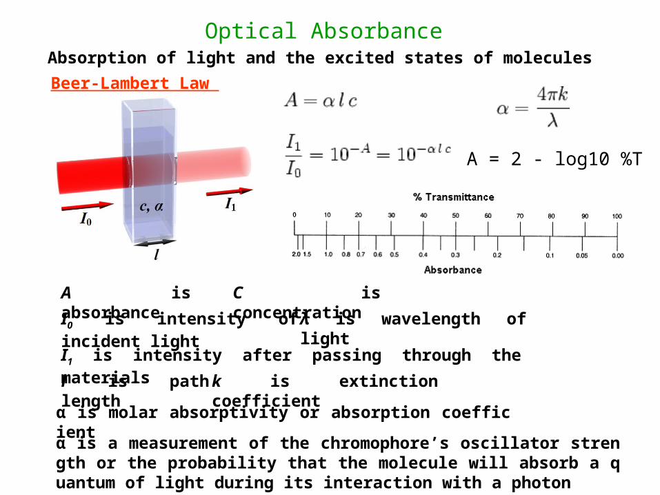
Optical AbsorbanceAbsorption of light and the excited states of molecules
A is absorbance I0 is intensity of incident light
I1 is intensity after passing through the materials
l is path length
C is concentration
λ is wavelength of light
k is extinction coefficient
α is molar absorptivity or absorption coefficient
Beer-Lambert Law
α is a measurement of the chromophore’s oscillator strength or the probability that the molecule will absorb a quantum of light during its interaction with a photon
A = 2 - log10 %T
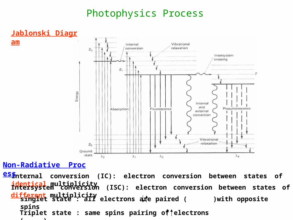
Photophysics Process
Internal conversion (IC): electron conversion between states of identical multiplicity
Intersystem conversion (ISC): electron conversion between states of different multiplicity
singlet state : all electrons are paired ( )with opposite spins
Triplet state : same spins pairing of electrons ( )
Jablonski Diagram
Non-Radiative Process
Photophysics Process
-
+
(
( )
)
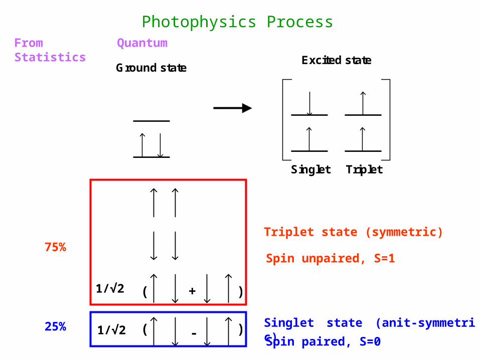
Ground stateExcited state
Singlet Triplet
1/√2
1/√2Singlet state (anit-symmetric)
Triplet state (symmetric)
Spin unpaired, S=1
Spin paired, S=0
From Quantum Statistics
25%
75%
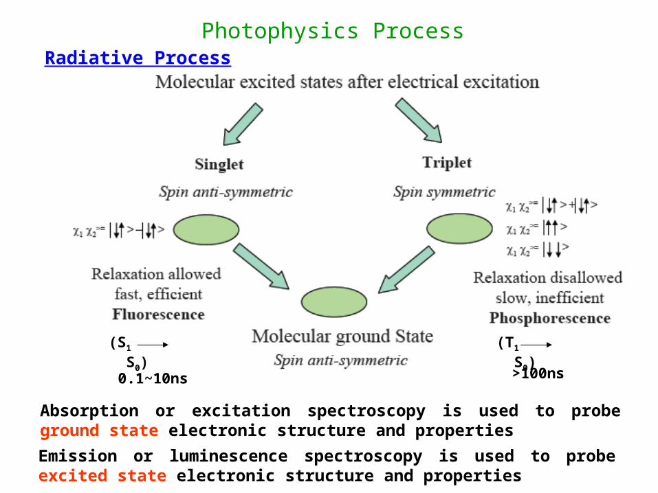
Photophysics Process
Absorption or excitation spectroscopy is used to probe ground state electronic structure and properties
Emission or luminescence spectroscopy is used to probe excited state electronic structure and properties
Radiative Process
(S1 S0) (T1 S0)
0.1~10ns >100ns
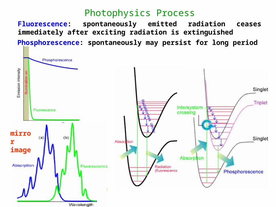
Photophysics ProcessFluorescence: spontaneously emitted radiation ceases immediately after exciting radiation is extinguished
Phosphorescence: spontaneously may persist for long period
mirror image
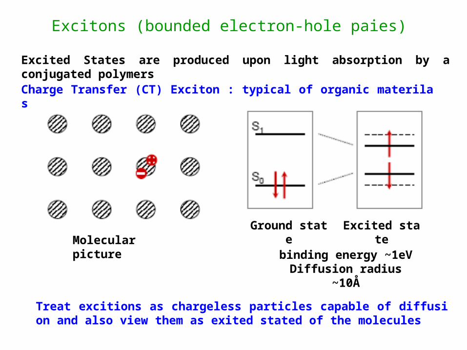
Excitons (bounded electron-hole paies)
binding energy ~1eVDiffusion radius ~10Å
Charge Transfer (CT) Exciton : typical of organic materilas
Excited States are produced upon light absorption by a conjugated polymers
Molecular pictureGround state Excited state
Treat excitions as chargeless particles capable of diffusion and also view them as exited stated of the molecules
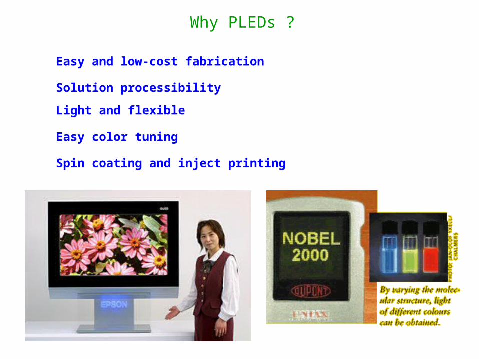
Why PLEDs ?
Easy and low-cost fabrication
Solution processibility
Light and flexible
Easy color tuning
Spin coating and inject printing
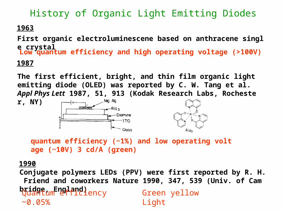
History of Organic Light Emitting Diodes
First organic electroluminescene based on anthracene single crystal
1963
1987
The first efficient, bright, and thin film organic light emitting diode (OLED) was reported by C. W. Tang et al. Appl Phys Lett 1987, 51, 913 (Kodak Research Labs, Rochester, NY)
1990Conjugate polymers LEDs (PPV) were first reported by R. H. Friend and coworkers Nature 1990, 347, 539 (Univ. of Cambridge, England)
Low quantum efficiency and high operating voltage (>100V)
Quantum efficiency ~0.05%
quantum efficiency (~1%) and low operating voltage (~10V) 3 cd/A (green)
Green yellow Light
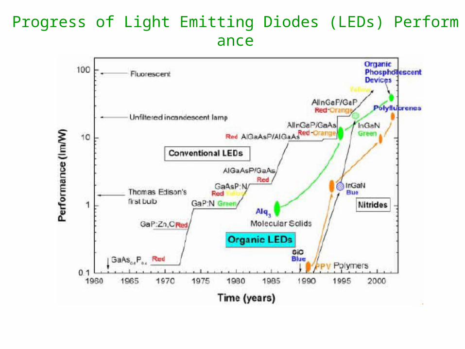
Progress of Light Emitting Diodes (LEDs) Performance
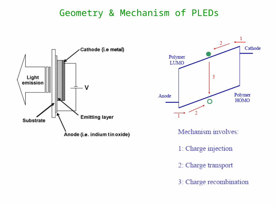
Geometry & Mechanism of PLEDs
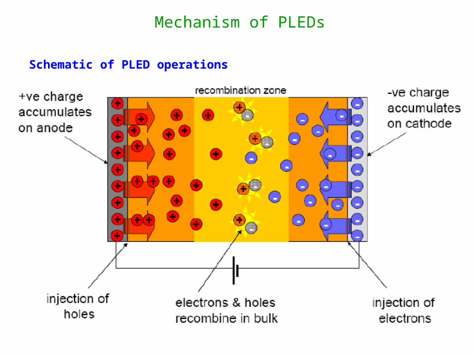
Schematic of PLED operations
Mechanism of PLEDs
LUMO
HOMO
Vacuum Level
ELMaterial CathodeAnode
IP
EA
Φ anode
Φ cathodeBarrier toelectroninjection
Barrier tohole
injection
Anode CathodeEL
MaterialLight
V
h+ e-
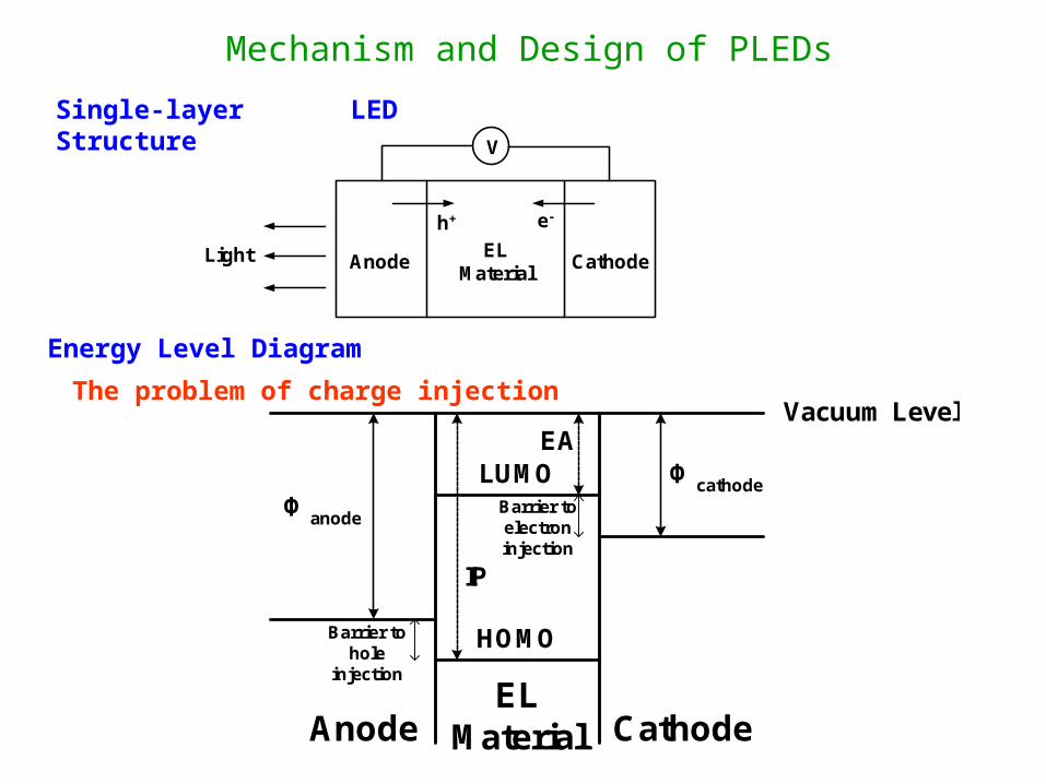
Mechanism and Design of PLEDsSingle-layer LED Structure
Energy Level Diagram
The problem of charge injection
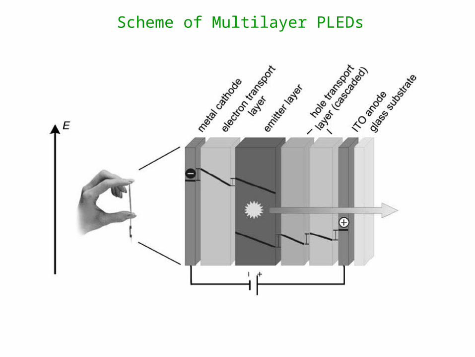
Scheme of Multilayer PLEDs
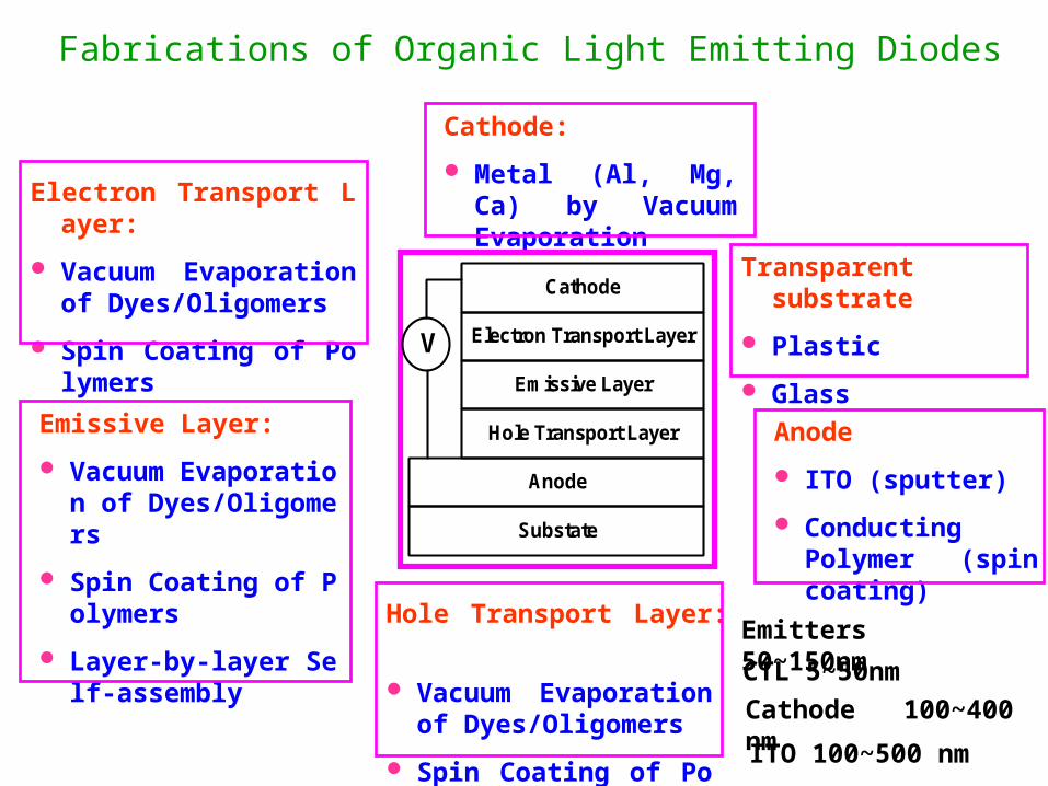
Fabrications of Organic Light Emitting Diodes
Electron Transport Layer:
Vacuum Evaporation of Dyes/Oligomers
Spin Coating of Polymers
Emissive Layer:
Vacuum Evaporation of Dyes/Oligomers
Spin Coating of Polymers
Layer-by-layer Self-assembly
Hole Transport Layer:
Vacuum Evaporation of Dyes/Oligomers
Spin Coating of Polymers
Cathode:
Metal (Al, Mg, Ca) by Vacuum Evaporation
Transparent substrate
Plastic
Glass
Anode
ITO (sputter)
Conducting Polymer (spin coating)
Emitters 50~150nm
CTL 5~50nm
Cathode 100~400 nm
ITO 100~500 nm
Cathode
Electron Transport Layer
Hole Transport Layer
Emissive Layer
Substate
Anode
V
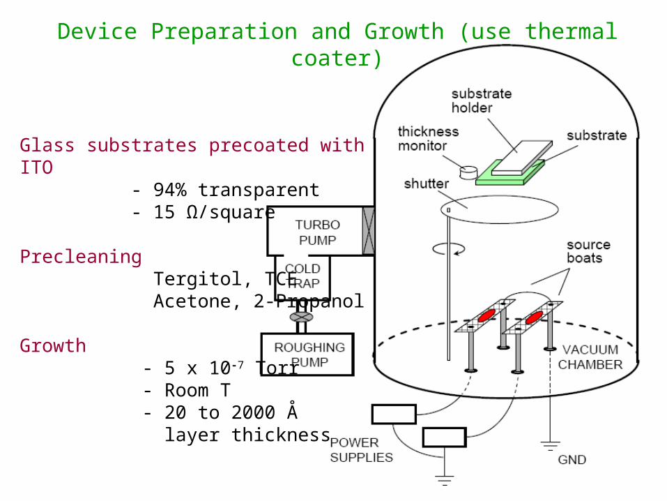
Glass substrates precoated with ITO - 94% transparent - 15 Ω/square
Precleaning Tergitol, TCE Acetone, 2-Propanol
Growth - 5 x 10⁻⁷ Torr - Room T - 20 to 2000 Å layer thickness
Device Preparation and Growth (use thermal coater)
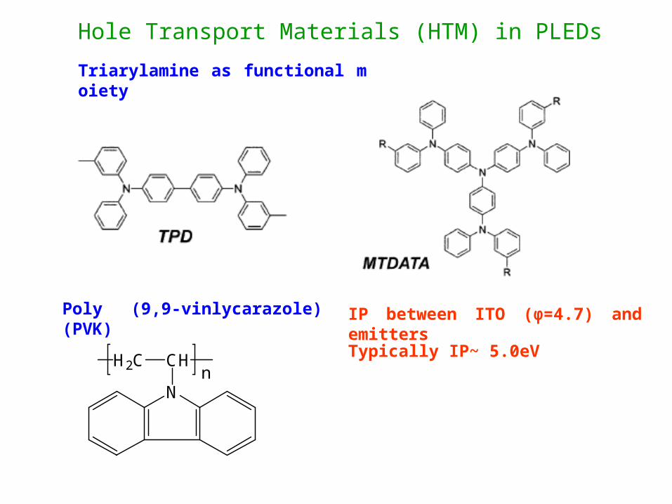
Hole Transport Materials (HTM) in PLEDsTriarylamine as functional moiety
N
CHH2Cn
Poly (9,9-vinlycarazole) (PVK) IP between ITO (φ=4.7) and emitters
Typically IP~ 5.0eV
SA Jenekhe et al, Chem Mater 2004, 16, 4556
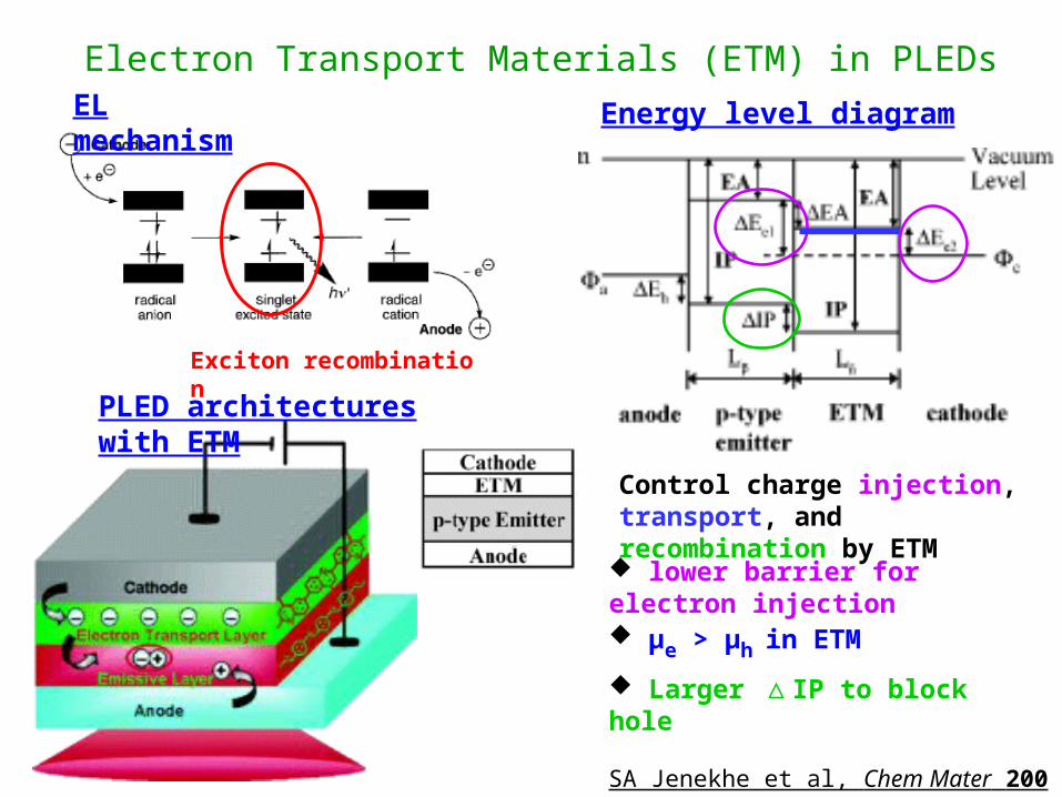
Electron Transport Materials (ETM) in PLEDsEL mechanism
Exciton recombination
PLED architectures with ETM
Energy level diagram
Control charge injection, transport, and recombination by ETM
lower barrier for electron injection μe > μh in ETM
Larger IP to block hole△
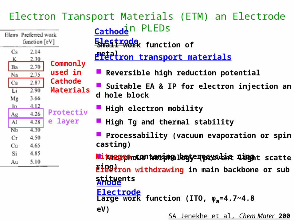
Electron Transport Materials (ETM) an Electrode in PLEDsCathode Electrode
Small work function of metal
Anode Electrode
Large work function (ITO, φa=4.7~4.8 eV)
Electron transport materials
Reversible high reduction potential
Suitable EA & IP for electron injection and hole block
High electron mobility
High Tg and thermal stability
Processability (vacuum evaporation or spin casting)
Amorphous morphology (prevent light scattering)
Nitrogen-contaning heterocyclic ring
Electron withdrawing in main backbone or substituents
Commonly used in Cathode Materials
SA Jenekhe et al, Chem Mater 2004, 16, 4556
Protective layer
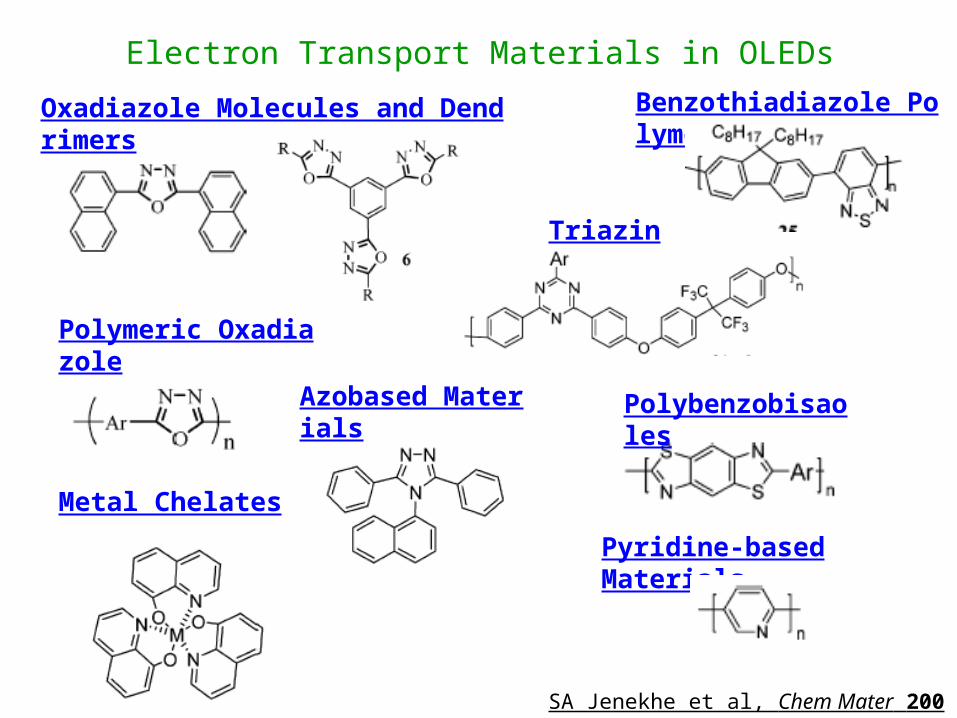
Electron Transport Materials in OLEDsOxadiazole Molecules and Dendrimers
Polymeric Oxadiazole
Metal Chelates
Azobased Materials
Triazines
Polybenzobisaoles
Benzothiadiazole Polymers
Pyridine-based Materials
SA Jenekhe et al, Chem Mater 2004, 16, 4556
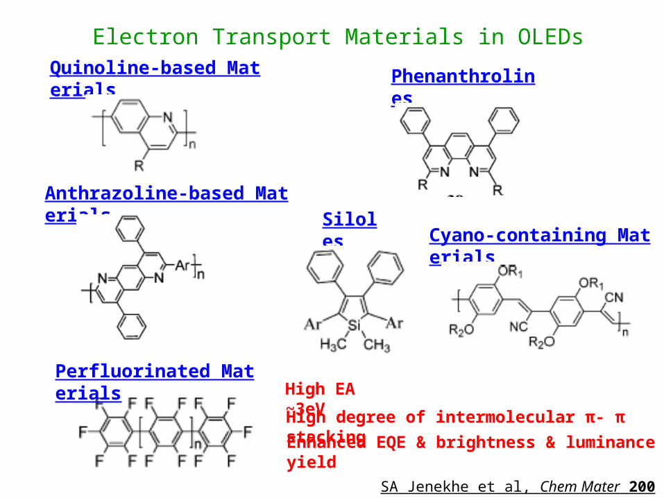
Quinoline-based Materials
Anthrazoline-based Materials
Phenanthrolines
SilolesCyano-containing Materials
Perfluorinated Materials
Electron Transport Materials in OLEDs
High EA ~3eV
High degree of intermolecular π- π stacking
Enhanced EQE & brightness & luminance yield
SA Jenekhe et al, Chem Mater 2004, 16, 4556
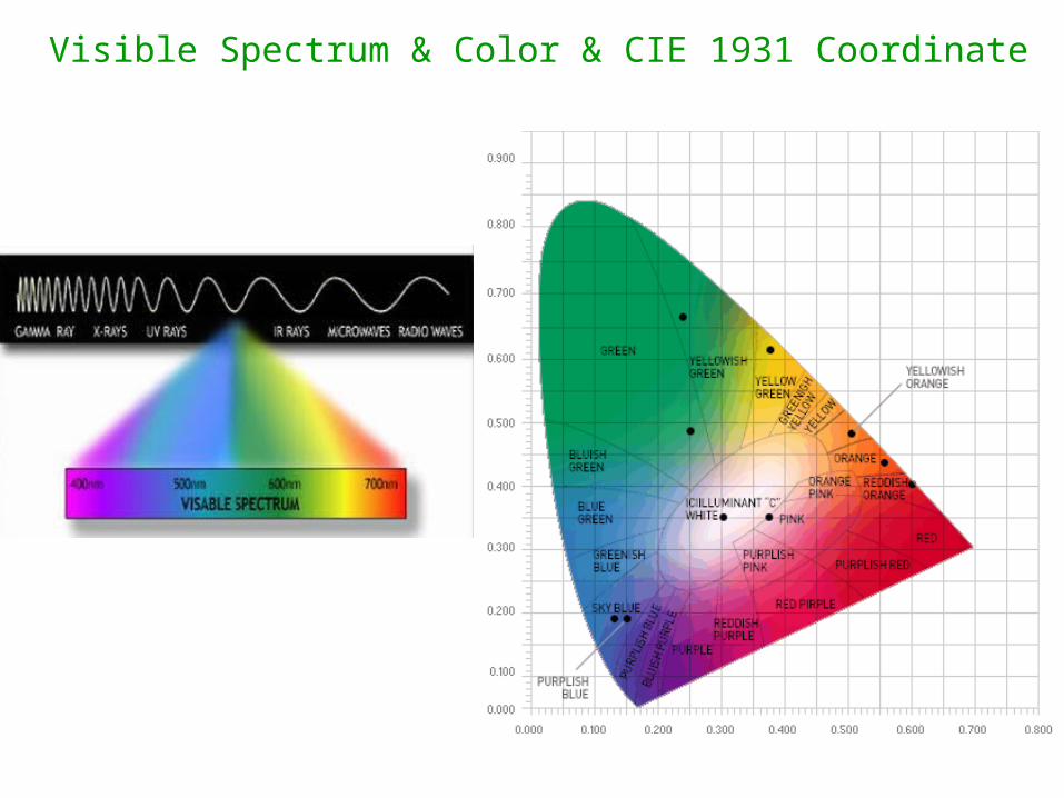
Visible Spectrum & Color & CIE 1931 Coordinate
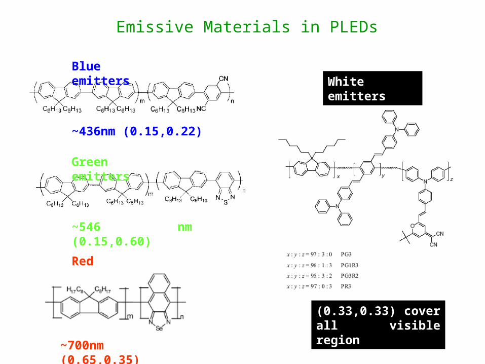
Emissive Materials in PLEDs
Blue emitters
Green emitters
Red emitters
White emitters
~436nm (0.15,0.22)
~546 nm (0.15,0.60)
~700nm (0.65,0.35)
(0.33,0.33) cover all visible region
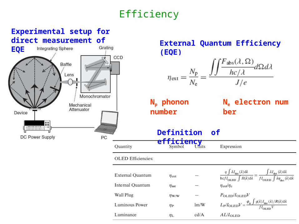
Efficiency
Experimental setup for direct measurement of EQE External Quantum Efficiency (EQE)
Np phonon number Ne electron number
Definition of efficiency
Cathode
Electron Transport Layer
Hole Transport Layer
Emissive Layer
Substate
Anode
V
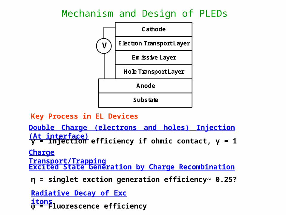
Mechanism and Design of PLEDs
Double Charge (electrons and holes) Injection (At interface)
Charge Transport/Trapping
Excited State Generation by Charge Recombination
Radiative Decay of Excitons
γ = injection efficiency if ohmic contact, γ = 1
η = singlet exction generation efficiency~ 0.25?
φ = Fluorescence efficiency
Key Process in EL Devices
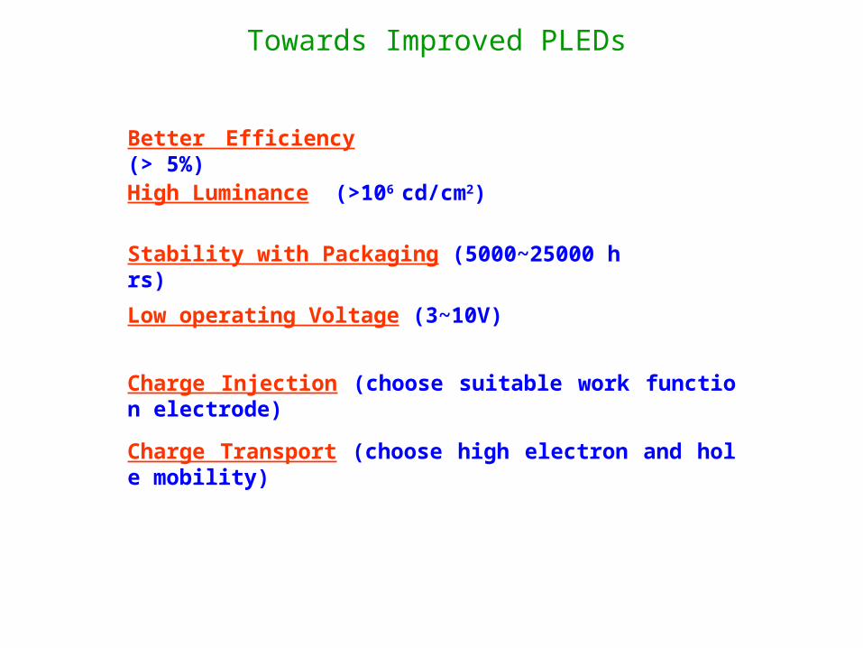
Towards Improved PLEDs
Better Efficiency (> 5%)
High Luminance (>106 cd/cm2)
Stability with Packaging (5000~25000 hrs)
Low operating Voltage (3~10V)
Charge Injection (choose suitable work function electrode)
Charge Transport (choose high electron and hole mobility)

THE ULTIMATE HANDHELD COMMUNICATION DEVICE
UDC, Inc.
Flexible Internet Display Screen
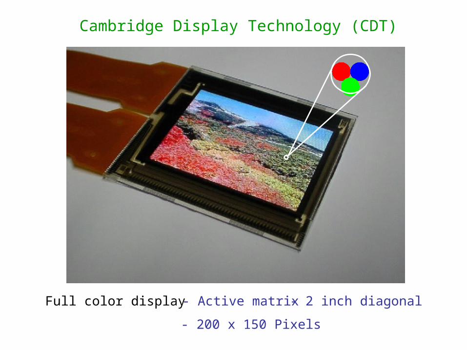
Full color display - Active matrix
- 200 x 150 Pixels
- 2 inch diagonal
Cambridge Display Technology (CDT)
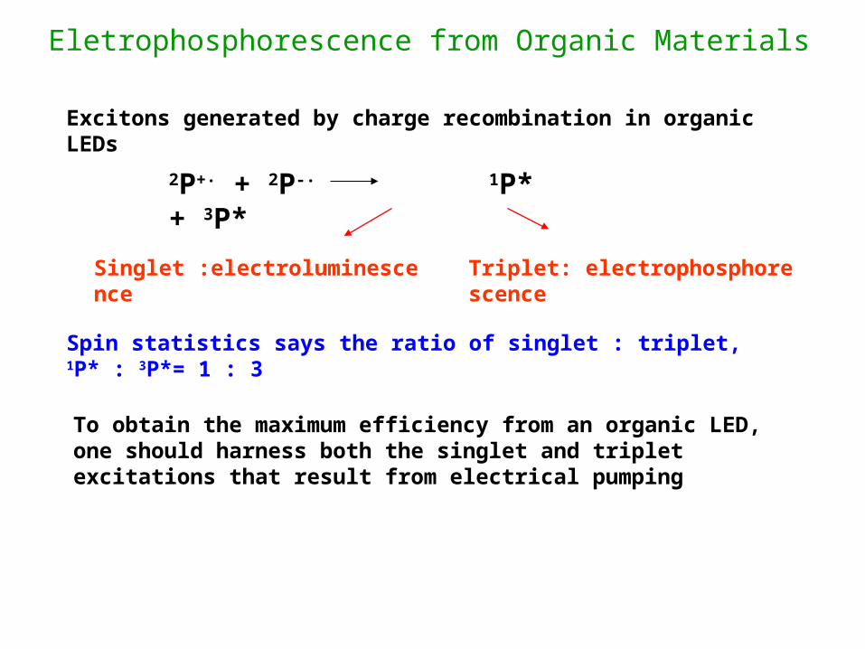
Eletrophosphorescence from Organic Materials
Excitons generated by charge recombination in organic LEDs
Spin statistics says the ratio of singlet : triplet, 1P* : 3P*= 1 : 3
To obtain the maximum efficiency from an organic LED, one should harness both the singlet and triplet excitations that result from electrical pumping
2P+‧ + 2P-‧ 1P* + 3P*
Singlet :electroluminescence Triplet: electrophosphorescence
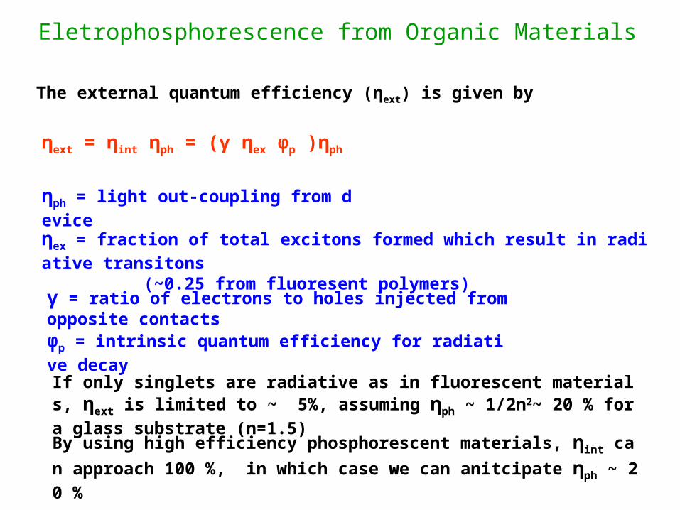
Eletrophosphorescence from Organic Materials
The external quantum efficiency (ηext) is given by
ηext = ηint ηph = (γ ηex φp )ηph
ηph = light out-coupling from device
ηex = fraction of total excitons formed which result in radiative transitons
(~0.25 from fluoresent polymers)
γ = ratio of electrons to holes injected from opposite contacts
φp = intrinsic quantum efficiency for radiative decay
If only singlets are radiative as in fluorescent materials, ηext is limited to
~ 5%, assuming ηph ~ 1/2n2~ 20 % for a glass substrate (n=1.5)
By using high efficiency phosphorescent materials, ηint can approach 10
0 %, in which case we can anitcipate ηph ~ 20 %
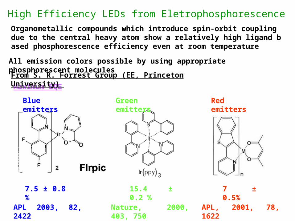
All emission colors possible by using appropriate phosphorescent molecules
Maximum EQE
Blue emitters Green emitters Red emitters
7.5 ± 0.8 % 15.4 ± 0.2 % 7 ± 0.5%
Nature, 2000, 403, 750APL 2003, 82, 2422 APL, 2001, 78, 1622
From S. R. Forrest Group (EE, Princeton University)
High Efficiency LEDs from Eletrophosphorescence Organometallic compounds which introduce spin-orbit coupling due to the central heavy atom show a relatively high ligand based phosphorescence efficiency even at room temperature
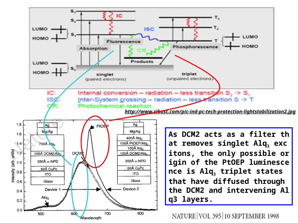
http://www.cibasc.com/pic-ind-pc-tech-protection-lightstabilization2.jpg
As DCM2 acts as a filter that removes singlet Alq3 excitons, the only possible origin of the PtOEP luminescence is Alq3 triplet states that have diffused through the DCM2 and intervening Alq3 layers.