Electromagnetic Metering Pump - Walchem Manual.pdf · Electromagnetic Metering. Pump ... Indicates...
66
. Read this manual before use of product IWAKI Electromagnetic Metering Pump EH-F series ( North America ) Instruction Manual This is patent pending product.
Transcript of Electromagnetic Metering Pump - Walchem Manual.pdf · Electromagnetic Metering. Pump ... Indicates...
httpwwwiwakipumpsjp
Read this manual before use of product
IWAKIElectromagnetic Metering Pump
EH-F series (North America)
Instruction ManualT596 0706
GermanyItalyDenmarkSwedenFinlandNorwayFranceUKSwitzerlandAustriaHollandSpainBelgiumUSA
TEL (49)2154 9254 0TEL (39)02 990 3931TEL (45)48 24 2345TEL (46)8 511 72900TEL (358)9 2742714TEL (47)66 81 16 60TEL (33)1 69 63 33 70TEL (44)1743 231363TEL (41)26 674 9300TEL (43)2236 33469TEL (31)297 241121TEL (34)943 630030TEL (32)1367 0200TEL (1)508 429 1440
AustraliaSingaporeIndonesiaMalaysiaTaiwanThailandHong KongChinaChinaChinaChinaPhilippinesKoreaVietnam
TEL (61)2 9899 2411TEL (65)6316 2028TEL (62)21 690 6606TEL (60)3 7803 8807TEL (886)2 8227 6900TEL (66)2 322 2471TEL (852)2 607 1168TEL (86)750 380 9018TEL (86)20 8435 0603TEL (86)10 6442 7713TEL (86)21 6272 7502TEL (63)2 888 0245TEL (82)2 3474 0523TEL (84)613 933456
IWAKI EUROPE GmbH IWAKI Italia SRL IWAKI Nordic AS IWAKI Sverige AB IWAKI Suomi Oy IWAKI Norge AS IWAKI France SA IWAKI PUMPS (UK) LTD IWAKI (Schweiz) AG IWAKI (Austria) GmbH IWAKI Holland BV IWAKI Iberica Pumps SA IWAKI Belgium nv IWAKI America Incorporated
FAX 2154 1028FAX 02 990 42888FAX 48 24 2346FAX 8 511 72922FAX 9 2742715FAX 66 81 16 61FAX 1 64 49 92 73FAX 1743 366507FAX 26 674 9302FAX 2236 33469FAX 297 273902FAX 943 628799FAX 1367 2030FAX 508 429 1386
IWAKI Pumps Australia Pty Ltd IWAKI Singapore Pte Ltd IWAKI Singapore (Indonesia Branch) IWAKIm Sdn Bhd IWAKI Pumps Taiwan Co Ltd IWAKI (Thailand) CoLtd IWAKI Pumps Co Ltd IWAKI Pumps (Guandong) Co Ltd GFTZ IWAKI Engineering amp Trading (Guangzhou) IWAKI Pumps Co Ltd (Beijing) IWAKI Pumps (Shanghai) Co Ltd IWAKI Chemical Pumps Philippines Inc IWAKI Korea CoLtd IWAKI Pumps Vietnam Joint Venture CoLtd
FAX 2 9899 2421FAX 6316 3221FAX 21 690 6612FAX 3 7803 4800FAX 2 8227 6818FAX 2 322 2477FAX 2 607 1000FAX 750 380 9078FAX 20 8435 9181FAX 10 6442 7712FAX 21 6272 6929FAX 2 843 3096FAX 2 3474 0221FAX 613 933399
( )Country codes
IWAKI COLTD 6-6 Kanda-Sudacho 2-chome Chiyoda-ku Tokyo 101-8558 JapanTEL(81)3 3254 2935 FAX3 3252 8892(httpwwwiwakipumpsjp)
This is patent pending product
Contents
Safety instruction middotmiddotmiddotmiddotmiddotmiddotmiddotmiddotmiddotmiddotmiddotmiddotmiddotmiddotmiddotmiddotmiddotmiddotmiddotmiddotmiddotmiddotmiddotmiddotmiddotmiddotmiddotmiddotmiddotmiddotmiddotmiddotmiddotmiddotmiddotmiddotmiddotmiddotmiddotmiddotmiddotmiddotmiddotmiddotmiddotmiddotmiddotmiddotmiddotmiddotmiddotmiddotmiddotmiddotmiddotmiddotmiddotmiddotmiddotmiddotmiddotmiddotmiddotmiddot 1~3
Product outline 1 Unpacking and inspection middotmiddotmiddotmiddotmiddotmiddotmiddotmiddotmiddotmiddotmiddotmiddotmiddotmiddotmiddotmiddotmiddotmiddotmiddotmiddotmiddotmiddotmiddotmiddotmiddotmiddotmiddotmiddotmiddotmiddotmiddot 42 Principle of operationmiddotmiddotmiddotmiddotmiddotmiddotmiddotmiddotmiddotmiddotmiddotmiddotmiddotmiddotmiddotmiddotmiddotmiddotmiddotmiddotmiddotmiddotmiddotmiddotmiddotmiddotmiddotmiddotmiddotmiddotmiddotmiddotmiddotmiddotmiddotmiddotmiddotmiddotmiddotmiddot 43 Model identification middotmiddotmiddotmiddotmiddotmiddotmiddotmiddotmiddotmiddotmiddotmiddotmiddotmiddotmiddotmiddotmiddotmiddotmiddotmiddotmiddotmiddotmiddotmiddotmiddotmiddotmiddotmiddotmiddotmiddotmiddotmiddotmiddotmiddotmiddotmiddotmiddotmiddotmiddotmiddot 54 Parts name middotmiddotmiddotmiddotmiddotmiddotmiddotmiddotmiddotmiddotmiddotmiddotmiddotmiddotmiddotmiddotmiddotmiddotmiddotmiddotmiddotmiddotmiddotmiddotmiddotmiddotmiddotmiddotmiddotmiddotmiddotmiddotmiddotmiddotmiddotmiddotmiddotmiddotmiddotmiddotmiddotmiddotmiddotmiddotmiddotmiddotmiddotmiddotmiddotmiddotmiddotmiddotmiddotmiddotmiddot 75 Specification middotmiddotmiddotmiddotmiddotmiddotmiddotmiddotmiddotmiddotmiddotmiddotmiddotmiddotmiddotmiddotmiddotmiddotmiddotmiddotmiddotmiddotmiddotmiddotmiddotmiddotmiddotmiddotmiddotmiddotmiddotmiddotmiddotmiddotmiddotmiddotmiddotmiddotmiddotmiddotmiddotmiddotmiddotmiddotmiddotmiddotmiddotmiddotmiddotmiddotmiddotmiddot 86 Operational function middotmiddotmiddotmiddotmiddotmiddotmiddotmiddotmiddotmiddotmiddotmiddotmiddotmiddotmiddotmiddotmiddotmiddotmiddotmiddotmiddotmiddotmiddotmiddotmiddotmiddotmiddotmiddotmiddotmiddotmiddotmiddotmiddotmiddotmiddotmiddotmiddotmiddotmiddot 97 Control display instruction middotmiddotmiddotmiddotmiddotmiddotmiddotmiddotmiddotmiddotmiddotmiddotmiddotmiddotmiddotmiddotmiddotmiddotmiddotmiddotmiddotmiddotmiddotmiddotmiddotmiddotmiddotmiddotmiddotmiddot 11
Installation 1 Before installation middotmiddotmiddotmiddotmiddotmiddotmiddotmiddotmiddotmiddotmiddotmiddotmiddotmiddotmiddotmiddotmiddotmiddotmiddotmiddotmiddotmiddotmiddotmiddotmiddotmiddotmiddotmiddotmiddotmiddotmiddotmiddotmiddotmiddotmiddotmiddotmiddotmiddotmiddotmiddotmiddotmiddotmiddot 132 Precaution on piping middotmiddotmiddotmiddotmiddotmiddotmiddotmiddotmiddotmiddotmiddotmiddotmiddotmiddotmiddotmiddotmiddotmiddotmiddotmiddotmiddotmiddotmiddotmiddotmiddotmiddotmiddotmiddotmiddotmiddotmiddotmiddotmiddotmiddotmiddotmiddotmiddotmiddotmiddot 153 Piping middotmiddotmiddotmiddotmiddotmiddotmiddotmiddotmiddotmiddotmiddotmiddotmiddotmiddotmiddotmiddotmiddotmiddotmiddotmiddotmiddotmiddotmiddotmiddotmiddotmiddotmiddotmiddotmiddotmiddotmiddotmiddotmiddotmiddotmiddotmiddotmiddotmiddotmiddotmiddotmiddotmiddotmiddotmiddotmiddotmiddotmiddotmiddotmiddotmiddotmiddotmiddotmiddotmiddotmiddotmiddotmiddotmiddotmiddotmiddotmiddotmiddot 154 Electrical wiring middotmiddotmiddotmiddotmiddotmiddotmiddotmiddotmiddotmiddotmiddotmiddotmiddotmiddotmiddotmiddotmiddotmiddotmiddotmiddotmiddotmiddotmiddotmiddotmiddotmiddotmiddotmiddotmiddotmiddotmiddotmiddotmiddotmiddotmiddotmiddotmiddotmiddotmiddotmiddotmiddotmiddotmiddotmiddotmiddotmiddot 21
Operation 1 Pump operation middotmiddotmiddotmiddotmiddotmiddotmiddotmiddotmiddotmiddotmiddotmiddotmiddotmiddotmiddotmiddotmiddotmiddotmiddotmiddotmiddotmiddotmiddotmiddotmiddotmiddotmiddotmiddotmiddotmiddotmiddotmiddotmiddotmiddotmiddotmiddotmiddotmiddotmiddotmiddotmiddotmiddotmiddotmiddotmiddotmiddotmiddotmiddot 272 Control unit operation middotmiddotmiddotmiddotmiddotmiddotmiddotmiddotmiddotmiddotmiddotmiddotmiddotmiddotmiddotmiddotmiddotmiddotmiddotmiddotmiddotmiddotmiddotmiddotmiddotmiddotmiddotmiddotmiddotmiddotmiddotmiddotmiddotmiddotmiddotmiddotmiddot 30
Maintenance 1 Troubleshooting middotmiddotmiddotmiddotmiddotmiddotmiddotmiddotmiddotmiddotmiddotmiddotmiddotmiddotmiddotmiddotmiddotmiddotmiddotmiddotmiddotmiddotmiddotmiddotmiddotmiddotmiddotmiddotmiddotmiddotmiddotmiddotmiddotmiddotmiddotmiddotmiddotmiddotmiddotmiddotmiddotmiddotmiddotmiddotmiddotmiddotmiddot 462 Maintenance and inspection middotmiddotmiddotmiddotmiddotmiddotmiddotmiddotmiddotmiddotmiddotmiddotmiddotmiddotmiddotmiddotmiddotmiddotmiddotmiddotmiddotmiddotmiddotmiddotmiddotmiddotmiddot 473 Dismantlement and assembly middotmiddotmiddotmiddotmiddotmiddotmiddotmiddotmiddotmiddotmiddotmiddotmiddotmiddotmiddotmiddotmiddotmiddotmiddotmiddotmiddotmiddotmiddotmiddotmiddotmiddot 494 Accessories middotmiddotmiddotmiddotmiddotmiddotmiddotmiddotmiddotmiddotmiddotmiddotmiddotmiddotmiddotmiddotmiddotmiddotmiddotmiddotmiddotmiddotmiddotmiddotmiddotmiddotmiddotmiddotmiddotmiddotmiddotmiddotmiddotmiddotmiddotmiddotmiddotmiddotmiddotmiddotmiddotmiddotmiddotmiddotmiddotmiddotmiddotmiddotmiddotmiddotmiddotmiddotmiddotmiddot 525 Exploded view middotmiddotmiddotmiddotmiddotmiddotmiddotmiddotmiddotmiddotmiddotmiddotmiddotmiddotmiddotmiddotmiddotmiddotmiddotmiddotmiddotmiddotmiddotmiddotmiddotmiddotmiddotmiddotmiddotmiddotmiddotmiddotmiddotmiddotmiddotmiddotmiddotmiddotmiddotmiddotmiddotmiddotmiddotmiddotmiddotmiddotmiddotmiddotmiddot 536 Outer dimension middotmiddotmiddotmiddotmiddotmiddotmiddotmiddotmiddotmiddotmiddotmiddotmiddotmiddotmiddotmiddotmiddotmiddotmiddotmiddotmiddotmiddotmiddotmiddotmiddotmiddotmiddotmiddotmiddotmiddotmiddotmiddotmiddotmiddotmiddotmiddotmiddotmiddotmiddotmiddotmiddotmiddotmiddotmiddotmiddotmiddot 58
Thank you for having selected IWAKI magnetic metering pump model EH-FRead this manual carefully for correct use This manual should be kept on hand by end user for quick referenceAs regards pump which is in special specification the handling of the pump should be in accordance with specific dimensions or authorized instructions
Contact us or your nearest dealer for further information
1
1 Safety instruction
Nonobservance or misapplication of the contents of the ldquoCautionrdquo section could lead to the personal injury to users or serious damage to the product
WARNINGNonobservance or misapplication of the contents of the ldquoWarningrdquo section could lead to a serious acci-dent which may result in death
CAUTION
Types of Symbols
Indicates that ldquoWarningrdquo or ldquoCautionrdquo must be exercised Inside this triangle a con-crete and practical image provided as a warning or caution message is depicted
Indicates a prohibited action or procedure Inside or near this circle a concrete and practical image of the activity to be avoided is depicted
Indicates an important action or procedure which must be performed or carried out without fail Failure to follow the instructions herein can lead to malfunction or damage to the pump
For the Safe and Correct Handling of the Pump
Safety Instruction section deals with important details about the handling of the product Before the use of the pump read this section carefully for the prevention of personnel injury or loss
Observe the instructions accompanied with WARNING or CAUTION in this manual These instructions are very important for protecting pump users from dangerous situations
The symbols on this instruction manual have the following meanings
2
Safety instruction
bull Qualified operators only This product must be operated by users with a full understanding of the pumps Person who has not
leaned about the pumps should not operate this productbull Turn off the power supply Dismantlementassembly without turning off the power supply may cause an electrical shock Before
engaging on any maintenance and inspection work be sure to turn the power supply switches off to stop the pump and the related devices
bull Risk of electric shock This pump is supplied with a grounding conductor and grounding-type attachment plug To reduce the risk
of electric shock be certain that it is connected only to a properly grounded grounding-type receptaclebull Wear protectors Getting wet with or coming in contact with the hazardous chemical liquid such as acid and alkaline
solution could lead to a serious injury Wear protective clothing such as a protective mask gloves and goggles according to the handled liquid during the work
bull Terminate operation Upon becoming aware of any dangerous signs or abnormal condition during operation terminate the
operation immediately and start it from the beginning againbull For specified application only The use of a pump in any application other than those clearly specified may result in the injury or the
damage to the pump Use the pump in accordance with the pump specificationsbull No modification Do not modify the pump Otherwise a serious accident may result We are not responsible for any
accidents or losses caused from any modifications to the pump without the first obtaining permission or instructions from Iwaki
bull Humid place prohibited This product is not water-proof construction If the pump is used at a highly humid place or the place
where liquid can splash the pump electrical shock or short-circuit may happenbull Do not step on tank
Stepping on tank the tank may fall down and cause personal injury or a loss Never step on tank
bull This pump has been evaluated for use with water only The suitability of this pump for use with liq-
uids other than water (such as acid and alkaline) is the responsibility of the user
bull Do not touch pump during the operation
Temperature of the pump surface during the operation is high Do not touch pump with the bare hands
bull Specified power only
Do not apply the voltage which is not specified on the nameplate to the product Otherwise damage or
fire may result Only the specified power source must be used
bull Pay attention to dry running
Do not run pump dry more than 30 minutes otherwise the screws of the pump head may loosen This
results in liquid leakage Secure the working condition for the prevention of dry running
Electrical Shock
No Remodeling
Wear protective gear
Prohibited
Prohibited
Caution
Do not wet or dampen
Caution
WARNING
CAUTION
Prohibited
Prohibited
Caution
Electrical Shock
3
Safety instruction
Prohibited
Prohibited
bull Do not wet or dampen If the electric parts or the wiring get wet by the unintentional liquid spillage a fire or an electrical
shock may occur and the controller breaks Install the system in a place free from liquid spillage or leakage Do not engage in wiring work with the wet hand
bull Do not operate pump with valves close Liquid spillage or the rupture of pump headpiping may occur due to an abnormal pressure rise Do
not run the pump with valves closebull Pay attention to the reciprocating motion of diaphragm Do not put any objects in bracket hole during the pump operation Diaphragm reciprocates inside the
bracket The contact with the object can cause malfunction bull Do not cover the pump body with cloth
The temperature inside the pump body rises when the pump body is covered This could lead to a fire Secure ventilationbull Prevention against freezing
Pump head may suffer damage due to freezing at below zero Be sure to remove the liquid from the pump body and piping after the use of pump
bull Ventilation Poisoning may result in the operation handling the toxic or odorous liquid Ventilate the operating site sufficientlybull Prevention of the spill-out accident Protective measures should be taken against any accidental spill-out as a result of unexpected damage
to the pump or the related pipingbull Damaged pump Never operate the damaged pumps The damaged pumps may cause leakage or electrical shockbull Handling of power cable Use of the defective or damaged power cable may result in a fire or electrical shock Do not scratch
modify or tug the power cablebull Install an earth leakage breaker (option) The operation of this product without using an earth leakage breaker may cause an electrical shock
Purchase an optional leakage breaker and install it in the systembull Frequent ON-OFF operation should be made via the STOP function with the signals to the STOP terminal In case
the ON-OFF operation without STOP function the maximum number of the ON-OFF must be 6 per an hourbull Follow the instruction manual Replace the consumable parts by following the descriptions in the instruction manual Do not disas-
semble the pump beyond the extent shown on the instruction manualbull Limited operating site and storage Do not install or store the pump in the following places where Flammable gas or material is used or stored The ambient temperature is extremely high (40 digC or higher) or extremely low (0 digC or lower) The pump is exposed to the direct sunlightbull Disposal of used pump The used or damaged pumps should be disposed of in accordance with the relevant local laws and
regulations (Consult a licensed industrial waste products disposing company)bull Loose fixation of mounting bolts can lead to liquid leakage
Be sure to tighten all the hex sock bolts (Number of bolts is 6 or 8) before an initial operation Periodically check all the bolts tight and re-tight as necessaryTightening torque is 255Nbullm Have the bolts tight gradually and diagonally
Caution
Prohibited
Caution
Caution
Caution
Caution
Prohibited
Electrical Shock
Do not wet or dampen
Caution
4
2 Product outline
2 Principle of operationIWAKI electromagnetic metering pump EH-F model is the diaphragm type metering pump of which dia-phragm is directly driven by the electromagnet force and consists of a pump head a driving unit and a control unit Reciprocating movement is made by the force of spring and the electromagnet generated by the pulse current coming from control unit The reciprocating movement is transferred to the diaphragm which is connected to a plunger to make volumetric change in pump chamber Pumping effect is obtained by the volumetric change and by the effect of valves which are placed in a pump head
Stroke lengthadjusting knob
Control unit
Driving unit (Pump body) Plunger
Pump head
Valve
Diaphragm
1 Unpacking and inspectionFor the purpose of confirming that the prod-uct delivered corresponds with your order after unpacking check whether-
bull The model flow rate discharge pressure andrated voltage on nameplate is as you ordered
bull All the accessories are in place Refer topage 52 Accessories
bull There is no transit damage and no loose boltnutbull Regarding union connection and flange connec-
tion types union sockets and flange units are packed apart from pump body
Note We ship the products with the greatest care but if you find any defects contact us or your nearest dealer
Handled liquid
5
Product outline
3 Model identification
1 Pump
EH - F 55 VC C6 - 10U -
Series code Driving unit code (Average power consumption) F 100 W Diaphragm effective diameter35 35 mm 45 45 mm 55 55 mm 70 70 mm
Wet end material
PartCode Pump head Valve O ring
Valve seat Gasket Diaphragm
VCPVC
Ceramic FKMPTFE
PTFE+
EPDM(Non wet end)
V6 SUS316 EPDMPC GFRPP Ceramic FKM
Special specification code01 - 99 Non standard material non standard connection or so
Connection hose diameter codeCode Connection hose dia
C6 empty 38 times empty 12C7 empty 58 times empty 34C8 12NPTC12 ANSI 150LB 12
Supply voltage codeCode Supply voltage10U AC115 V (with a plug)20U AC230 V (with a plug)
Allowable voltage range FrequencyAC1035 V - 1265 V 50-60 HzAC207 V - 253 V
Material code PVC Polyvinyl chloride PTFE Poytetrafluro ethylene (Teflon) FKM Fluor rubber (Acid resistant Viton) GFRPP Glass fibber reinforced polypropylene EPDM Ethylene propylene rubberNote Regarding handled liquid acid and alkaline solution is transferred depending on wet end material
Acid solutionAlkaline solutionAcid solution
6
Product outline
2 Controller
EHC - F 10U -
Controller unit type for EH-F EHC Controller EH pump driving unit code
Supply voltage code
Special specification code 01~99 Special specification
Code Average power consumptionF 100W
Code Supply voltage10U AC115V20U AC230V
Allowable voltage range FrequencyAC1035V - 1265V
50-60HzAC207V - 253V
7
Product outline
4 Parts name
1 Pump parts
Pump headLock screw
Driving unit
Control panel
Control unit
Stroke lengthadjusting knob
Socket cord
MAN DIV MULT ANAR V
OVER P12 LOCK Err SET
spm
mA
LED lights orange when Pre-STOP signal comes from level sensor or lights redly when STOP signal comes
Screen indicates operation states and setting values in figures and letters
StartStop key is used tostartstop pump operation
EXT keyis used to start pumpingin EXT operation mode
ON lamp lights as turning on power and blinks synchronously with each stroke
Up key is used to increase the setting values and to change the setting items Pressing Up and Down key at once can have the pump running at full spm
Down key is used to decrease the setting values or to change the setting items Pressing Up and Down key at once can have the pump running at full spm
2 Control unit
8
Product outline
5 Specification
1 Pump specification
2 Control unit specification
Operationmode
MAN (Manual operation) 1 - 240 spm
EXT
DIV (Pulse dividing) 1 - 9999MULT (Pulse multiply) times1 - 9999ANA R (Analog rigid) 4-20 0-20 20-4 20-0 mAANA V (Analog variable) 2 points in a range of 00-200 mA 0 - 240 spmEXT mode consists of the above 4 modes
Display
LCD 14 seg 5 digits spm Operational states and Settings
LEDON Green Lights as turning power on
Blinks synchronous with each strokeSTOP OrangeRed Lights orange when Pre-STOP is activated or lights redly when STOP is activated
Operation 4 keys STARTSTOP EXT UP DOWN
Control function
STOP Pump keeps running when Pre-STOP is activated or stops when STOP is activated
Self priming Pump operates at full speed when both Up and Down keys are depressed together
Key lock Lock and release key padsBuffer memory ONOFF setting is changeable (Initial setting is OFF)
InputPulse No-voltage contact Maximum 100 HzCurrent Range of DC0 - 20 mA (Input resistance 200 Ω)Level sensor Potential free contact or open collector 2-step contact
Output Photo MOS Relay ACDC 24 V 01 Aspm synchronous output The maximum input pulse frequency is 100 Hz however the maximum frequency is variable
depending on the setting of anti-chattering On-time of pulse requires 5 ms or more when ST 05 is selected
5060Hz
ModelsMax discharge
capacitymlmin(GPH)
Max discharge pressureMPa(PSI)
Stroke speed variable range
spm
Stroke length variable range
mm()
Average power
consumption
W
Masskg
EH-F 1 - 240 09 - 225(40 - 100) 100
45 750(119) 07(102)55 1200(190) 045(65)
16
70 2000(317) 03(44)
35 500(79) 10(145)
Note 1 Performance is obtained by pumping clean water at ambient temp at a rated voltage2 Discharge capacity is the value at max discharge pressure (100 stroke length 100
stroke rate) When discharge pressure is low pump discharges liquid much more than the discharge capacity shown above
3 Permissible ambient temperature 0 ~ 40 deg C 4 Permissible liquid temperature VC V6 0 ~ 40 deg C PC 0~60 degC 5 Permissible voltage fluctuation Within plusmn10 of the rated voltage6 Ask us or our distributor for special cases such as transferring slurry liquid
9
Product outline
6 Operational function
1 Manual operation and keys are used to set the number of strokes between 1 and 240 spm The pump startsstops
operation by pushing START STOP key The number of strokes is adjustable in the both pump states of running and stop
ON
ON
OFF
ON ON
STARTSTOP key
Operation
Stop
Operation
Pump operation
External signals
ON
OFF
Pump operation
1 2 3 4 1 2 3 4 1 2 3 4
Set value 14 in dividing operation
2 Pulse dividing operationIn this mode pump runs in the dividing operation for external pulse signals Dividing ratio is variable within the setting range between 9999 1 and 1 1 The upper limit of the number of strokes in the pulse dividing operation is equivalent to the maximum number of strokes in manual operation When the input signals over the upper limit stroke speed is incoming the residual signals can be stored up to 65535
External signals
Pump operationON
OFF
Set value 4 in multiply operation
1 2 3 4 1 2 3 4 1 2 3 4
3 Pulse multiply operationIn this mode pump runs in the multiply operation between 1 and 9999 times for an external pulse signal and stops automatically The number of strokes in the pulse multiply operation is equivalent to the number of strokes in manual operation The incoming pulse signals during the multiply operation motions are cancelled and are stored up to 65535
10
Product outline
4 Analog control operation ANA R(analogue rigid) mode
Pump operates within the range of 0-240 spm in proportion to the external signals between 0-20 mA4 (4-20 20-4 0-20 20-0) patterns are provided and the pump operates within 0-240 spm in proportion to the external signals in each patternIn the 4-20 or 20-4 pattern a breaking detective function becomes active automatically The function stops the pumping operation below 4 mA And an error indication DISCN blinks on the display of con-trol unit When this function is active check wiring This function can be released with STARTSTOP key
42
3
1
Num
ber o
f stro
kes
240
0 4 20
(spm)
Analog input(mA)
Conditions
The left graph is in the following patterns 4 - 20 20 - 4 0 - 20 20 - 0
240220
60
0 6 2017
(spm)
Analog input (mA)
P1
P2
Num
ber o
f stro
kes
Conditions
The left graph is in the following settingP 1 = 6 mA 60 spmP 2 = 17 mA 220 spm
ANA V(analogue variable) modePump operates within the range of 0-240 spm in proportion to the external signals between 0-20 mA Setting 2 points can draw a straight line Depending on the position of the 2 points 0 spm may not come at 0 mA in some cases When the stroke speed could become over 240 spm at some mA due to the set-ting pump speed is limited to 240 spm
11
Product outline
7 Control display instruction
1 Control unit
ON STOP
EXT
EH-F ControllerSTARTSTOP
DIVMAN
OVER P1 2 LOCK Err SETmA
spmMULT ANAR V
Manual operation indication (MAN)shows pump is in manual operation
indicationshows pump is running for self-priming at maximum stroke speed and calls userrsquos attention
mA indicationappears when setting amperage in EXT setting mode for analog control operation
SET indcationappears in user mode and EXT setting mode
Stop indicationappears during Pre-STOP or STOP signal input
Stroke speed indication appears when displayshows stroke speed
Pulse dividing indication (DIV)shows pump is in pulse dividing operation or pulse dividing ratio is being set
Pulse multiply indication(MULT) shows pump is in pulse multiply operation or pulse multiply ratio is being set
Display shows operational state and set values in figures and letters
STARTSTOP keyis used to startstop pump operationThis key is also used to confirm each set value in set modes and used to move to wait mode
EXT keyis used to start pump operation in EXT operation modes
Over indicationlights when incoming signals are surplus to 240 spm in EXT operation
P1 and P2 indicationsappear when 2 points(P1 P2) are set in ANA V(analog variable) mode for analog control operation
Lock indicationappears when keys are locked
ON lampappears as turning on power and blinks synchro-nously with each stroke
Error indicationappears when an error occurs
Analog control operation indication (ANA R ANA V)ANA R indicates pump is in analog rigid operation or setting mode ANA V indicates that pump is in analog variable operation or setting mode
Down key is used to decrease the setting values and to change the setting items Pressing Up and Down key at once can have the pump running at full spm
Up key is used to increase the setting value and to change the setting items Pressing Up and Down key at once can have the pump running at full spm
12
Product outline
2 Typical indications
3 Warning indications
Indications Show
Pump is operating in the manual operation modeThe display shows the set spm
Pump is operating in the analog control mode(ANAV) of the EXT operation Display indicates 168 spm
The stroke speed is being set while pump is operating in the multiply operation(MULT)
Pump is being stopped via STOP input while operating in the dividing operation(DIV)
MAN spm
LOCK SET mA
MAN ANA V spm
MULT
SET
DIV spm
Indications shows
Key lockAll the key operation can be ineffective in order to prevent any per-son other than user from operating the pump This function can be active by pressing STARTSTOP key for 5 seconds in any pump states and LOCK indication appears Key lock function can be released by pressing STARTSTOP key for 5 seconds when LOCK indication appears on the display
The left indication appears when input signal is below 4 mA with the 4-20 or 20-4 pattern in ANA R (Analog rigid) mode In this state pump is under suspensionBy pushing STARTSTOP key once this error is released and the mode moves to waiting mode Check wiring and signals
OVER indication appears when incoming signals are surplus to 240 spm in EXT operation
MAN spm
LOCK SET mA
ANAR
Err
spm
MAN spm
OVER
13
Installation
1 Before installation
Working without disconnecting the power supply may cause an electrical shock Before engaging upon any working procedures involving the pump be sure to turn the power supply switches off to stop the pump and the related devices
Upon becoming aware of a dangerous sign or an abnormal condition while engaging on the installation terminate the work immediately and start it from the beginning again
Do not operate the pump on the voltage which is not specified on the nameplate Failure to do so may result in damage or a fire Be sure to earth the pump
Do not place any dangerous materials or flammable objects near the pump for the sake of safety
WARNING
CAUT ION
1 Dropping the pump or subjecting it to a strong impact may result in the faulty performance Handle the pump with care Do not use the damaged pump for the prevention of the electri-cal leak or shock
2 When installing pump avoid the places where the pump is exposed to the direct sunlight the ambient temperature is above 40 digC or the relative humidity is above 85 Though the pump has a simple waterproof and dust-proof structure it is recommended to protect the pump with a cover when installing it outdoor
3
Installation
14
3 Select a level floor and use the four M6 bolts to firmly anchor the pump so as not to allow any vibration If the pump is inclined the discharge amount may decrease considerably
4 Pump should be installed in a well-ventilated place in summer and free from freezing in win-ter
6 Place the pump as close to the suction tank as possible realizing a flooded suction system (It is recommended the pump should be located lower than the suction-side tank)
7 If the pump is used to feed some liquid that gen-erates air bubbles easily (sodium hypochlorite hydrazine solution etc) the system must be positioned in a cool dark place away from direct sunlight If a tank is installed realize a flooded suction system
5 Select the installation site convenient for the future maintenance and inspection
2 Precaution for piping Piping vibrates due to the pulsation from pump Piping should be supported in order to prevent the vibra-
tion Install an air chamber or an accumulator to reduce the pulsation Ask us for further information Be careful not to have hose bend when arranging tubing It is recommended to arrange the short piping as much as possible The longer piping length the more
pressure drops and can exceed the allowable pressure of pump and can cause the over feed phenom-enon
It is recommended an automatic air bleed valve or a pressure relief valve should be installed in order to release the pressure of discharge piping for maintenance
It is recommended to install a relief valve on the discharge side piping that releases pressure automati-cally
Install a pressure gauge on the discharge side piping in order to measure the pressure inside the piping When installing EH-F pump with the flange connections or the union connections be sure to have the
connections on the discharge side fixation on wall pillar or the frame of equipment for the prevention of vibration Make sure that the piping is fixed as well
CAUTIONIncomplete fixation of pump and piping can lead to the damage to these products Significant vibration often results from the incomplete support for the discharge side connection of pump In case the direct support for the flange or union connection can not be secured try to support pump close to the discharge connection as much as possible
15
Installation
Check valve
Air bleedValve
Discharge hose
Pump
Tree way joint
Accumulator
Drain valve
Discharge valve
Back pressure valve
Pump
Suctionvalve
Air bleed valve
Airchamber
Pressure gauge
Relief valve
3 Piping1 Recommended piping drawings
Arrange piping to meet the suction and dis-charge requirement Especially pay attention to piping arrangement in case of handling the slurry which has settling property
Installation
16
Hose
Hose stopper
Fitting spacer
O ring
Fitting nut
Place hose stoppers with R surfaceface to face with fitting spacer
Hose
Hose stopperFitting spacer
O ring
Fitting nut
Fitting
Suction port
Pump head
2 Piping arrangement1 For hose connection first fit a fitting nut and then a
hose stopper and a fitting spacer in the last place If the hose stopper is not fitted properly leakage may occur and suction amount may decrease
The hose end should be secured by a hose stop-per Insert a hose end into a fitting spacer via a fitting nut and a hose stopper Then squash the hose end between the hose stopper and the fit-ting spacer Finally screw the fitting nut in
The hose stopper should be placed with its R surface face to face with the fitting spacer An incomplete hose stopper fixation or a reverse hose stopper placement can lead to leakage or insufficient suction
CAUTIONReverse hose stopper placement can dam-age hose
Fitting nut is made of plastics The fitting nut may break when it is tightened excessively
If attached hose is not long enough prepare a substitute hose such as chloroethene braided hose and polyethylene hose with a suitable bore to the hose fitting spacer
CAUTIONIt is very dangerous to attach the different size hose It may come off
Insert the fitting spacer into hose as deep as possible If the insertion is not enough hose may come off and leakage may result
Be careful not to lose the attached O rings Leakage or suction failure may result without an O ring
2 Hose connection tends to loose if liquid or ambient atmosphere is higher than normal temperature Re-tighten the fitting nut properly after starting opera-tion Be careful not to tighten the nuts too much
3 When fitting the hose again after detaching it for maintenance cut the end of hose off about 10 mm and insert it
17
Installation
4 Check valveEH-F35 45 (VCV6PC) types are attached with a check valve Fit the check valve to piping in the fol-lowing cases
1 The suction side liquid level is higher than the dis-charge side liquid level (Fig A) When injection point is below the liquid level of suction side at atmospheric pressure
2 The suction side pressure is higher than the discharge side pressure (Fig B)
3 The discharge side liquid level is higher than the suction side liquid level but the differential height between both liquid level is 5 m or below (Fig C)
4 The loading pressure of piping resistance and dis-charge head to the pump is under 013 MPa
Suction side Discharge side
Figure A
Figure B
5m
Figure C
To chemical tankor vessel
Remove check valve
3 Piping for bleedingPrior to bleeding disconnect hose and point a hose end at a suction tank or vessel Remove a check valve if it is attached on the discharge side piping
18
Installation
R12
Oslash12
5 Check valve mounting1 Tap the female thread of NPT12 at an injection
point Check valve is provided with the male thread of R12 Cut off the unused portion to fit it on a pip-ing
2 Apply seal tape on the threaded portion of the check valve and screw it in the injection point Pinch the check valve body lightly with a spanner and tighten it for easy mounting
3 When fitting a hose into a check valve with the check valve on main pipe tighten the fitting nut holding the check valve body by hand
4 Cut the end of check valve(empty 12) accordingly when mounting it in a small pipe It is recommended the end of the check valve comes at the centre of pipe bore
It is recommended to mount a check valve via a valve for maintenance Provide NPT12 female thread and screw it in Valve should be resistant to the chemical liquid in use
Valve
Check valve
Check valve body
Apply seal tape
Fitting nut
Pipe
Cut the end nozzle offif it is too long compared topipe bore
6 Flange connection and union connection1 Flange units and union sockets are packed apart from pump body Fit the flange units or the union sockets to
pump body before use Refer to the following figures2 Secure the sealing by fitting O rings to each connection
CAUTIONWhen mounting flange units or union sockets to pump body be careful not to allow O ring to get out of the groove Especially pay attention to the O ring on the groove on suction side
3 Fix the flange units or the union sockets to the pump body by tightening fitting nuts In this case first tighten the fitting nuts by the hand and then re-tighten it by 90 degrees with a spanner
CAUTION
Fitting nut is made of plastics The fitting nut may break when tightened excessively
Flange connection type
19
Instillation
Flange
Flange
Fitting nut
O ring
O ring
Elbow
Pump body
Fitting nut
Drain
Discharge
Air chamber
7 Accumulator and air chamber mountingInstall an accumulator or an air chamber on piping for the prevention of the vibration from the pulsation of pump discharge hose
20
Installation
8 Piping (General notes)1 Keep piping short and less bends Do not make the projections where air can remains
2 Support piping to avoid having the pump subject to the piping weight especially when wet-end mate-rial is made of PVC
3 In case of transferring the slurry which tends to settle do not make U shape on piping A drain plug is required at the lowest portion of piping as well
4 In case of transferring the viscous or toxic liquid or the liquid which tends to settle provide the piping for cleaning for the purpose of maintenance
5 In case of transferring the high temperature or low temperature liquid the telescopic motion of piping from temperature variation should be taken into consideration
6 Select pipe materials based on a through examination of the corrosive resistance and the estimated pressure applied to piping
7 Do not allow any adhesive agent to get in pump when connecting PVC-made pipe on the discharge side piping
8 Clean the inside of piping before installing pump in it
9 A relief valve is required to protect pump and piping Install a relief valve on the discharge piping near the pump
9 Suction piping1 Regarding suction piping a flooded suction system should be realized The bore of suction piping is
recommended to be larger than that of pump suction port
2 Each joint of suction piping needs to be mounted carefully in order to prevent air from coming in Air influx into piping may cause discharge performance failure and instability
10 Discharge piping1 Mount a relief valve on the discharge piping near pump A discharge valve should be mounted beyond
the relief valve
2 The pressure resistance of discharge piping should be higher than the set pressure of relief valve Mount each joint carefully
21
Installation
4 Electrical wiring
1 Power cord connection
Electrical works and the handling of power source must be done by qualified person
Do not operate pump with the wet hand
Make sure that power is not turned on while working on wirng
Do not dismantle electronic circuit
Electronic circuit may be broken Never apply other voltages than a rated voltage
WARNING
CAUT ION
High power equipment
CAUTION Avoid sharing a power source with a high
power equipment This can lead to the fail-ure of the electronic circuit of control unit due to extremely large surge voltage
The noise from an inverter can cause fail-ure
22
Installation
P
Surge absorption element
PNoise cut transformer
CAUTION
2 Wiring procedure
Electronic circuit of control unit may be failed by extremely large surge voltage Do not use the pump near to the high power equipment of 200V or more which may generate large surge voltage If the use of high power equipment is inevitable take either of the following measuresa Install a surge absorption element such
as varister with 2000A or more durability on the power point
b Install a noise cut transformer
CAUTION
Only qualified operatorsservice staff should be in charge of the related electrical arrange-ment and control of the power source Failure to observe this instruction may result in injury to person or damage to assets
Never connect wires while power is turned on otherwise an electrical shock or a short-circuit of controller may result Be sure to turn off power before wiring
Internal circuit is still electrified right after turning off power Take 1 minute or more to start wiring
Do not band a power cable either electrical wires or relay output wires
Earthing wire is equipped with a jumper pin Keep the jumper pin equipped in use
Do not combine the EXT or STOP signal line with a power cord or a power cable Do not com-bine power source line with the EXT or STOP signal line by a concentric cable (5 wires cable or so) Otherwise noise come about through EXT and STOP wires due to the induction effect from power cable and it may results in wrong operation or the failure of pump
Regarding frequent ON-OFF operation it is recommended to stop pump thorough STOP input terminal but not by connecting or disconnecting power source When connecting and discon-necting power cord can not be avoided it should be within 6 times an hour
23
Installation
Procedure to connect the signal cordUse DIN connector of five poles and four polesThe following connectors made by Binder in Germany are recommendedAsk IWAKI for the detail of Binder connector 5 poles 713 series 99-0436-10-05 for input signal 4 poles 715 series 99-0430-15-04 for level sensor
The following connector made by Hirschmann in Germany is recommendedAsk IWAKI for the detail of Hirschmann connector 4 poles GDS307 for output
The following procedures are based on the connector made by Binder and HirschmannIf a similar connector is used the wiring should be made according to the instruction manual of the manufacturer of connector
In case of Binder connector(1) Dismantle the connector and pass the wire through it Outer diameter of the cable should be oslash4-6
Using the different cable in diameter the connector can not be sealed properly
(2) Strip the cable ends and insert wire to the appropriate positions and connect them with screwsThe maximum allowable cross section of the wire is 075mm2
(3) After connecting the wire assemble the connector securely Slightly pull the cord to confirm that the cord connection is secured Perfect sealing can not be obtained unless the cord connection is loose
24
Installation
In case of Hirschmann connector(1) Dismantle the connector and pass the wire through it Insert a minus screw driver into the place shown by
ldquoLIFTrdquo and lift it up Outer diameter of the cable should be 35-6 mm Using the different cable in diam-eter the connector can not be sealed properly
(2) Strip the cable ends and insert wire to the appropriate positions and tighten them with screwsThe maximum allowable cross section of the wire is 075mm2
(3) After connecting wire assemble the connector securely Slightly pull the cord to confirm that the cord connection is secured Perfect sealing can not be obtained unless the cord connection is loose
Terminal position
NA Not Applicable
Connection of level sensorThe controller corresponds to two stage level sensor Connect the pre-alarm signal to Pre-STOP and the alarm signal to STOP When the pre-alarm signal comes in the orange lamp lights but the pump does not stop When a contact type is used connect wires to STOP and COM2 For open collector output level sensor Pay attention to the polarity Pre-Stop and STOP are plus (+) and COM2 is minus (-) (Max charged voltage 5V Current 18mA) For contact output level sensor Use the one designed for electronic circuit and the minimum applicable load of 1mA or less
Connection inside connector 1 STOP 2 Pre-STOP 3 Free 4 COM2
1
2
3
4 CLOSE
ON
PUMP
Level Sensor(STOP)
OPEN
Pulse
COM
+12VDC
NA
ANA(4-20)
Pre-STOP
STOP
COM
NA
OUT
25
Installation
Stop functionStop function is the function to stop the pump by the external signal Connect the wires to STOP and COM2 in the same way as the level sensor connection
CAUTION
Frequent stop and start of pump should be done by using STOP function (ON and OFF of STOP terminal) If you can not use STOP function and are forced to operate pump by turning OFF and ON of power source ON and OFF of power source should be limited to six times an hour
Pulse signal inputPulse signal input is used when the pump runs in the DIV or MULT of EXT modeDIV means dividing and MULT means multiply In case of open collector signal Pay attention to the polarity Pulse is plus (+) and COM1 is minus (-) (Max charged voltage 5V Current 18mA) In case of contact signal Use the one designed for electronic circuit and the minimum applicable load of 1mA or less
Connection inside connector 1 Free 2 Pulse 3 Free 4 12VDC 5 COM
3
2
4
15
Analog signal inputAnalog signal input is used when the pump runs in ANAR or ANAV of EXT modeANAR means analog rigid and ANAV means analog variable
Connection inside connector 1 ANA 2 Free 3 Free 4 Free 5 COM
3
2
4
15
26
Installation
Output signalOUT Photo MOS relay outputStandard is output synchronous with stroke Output is activated synchronous with each pump stroke
Connection inside connector 1 OUT 4 OUT
OUT 1
2
34
Surge voltage The electronic circuit of the control unit may be affected by excessively high surge voltage Do not operate the pump near the high-power elec-trical equipment of 200V or above that generates high surge voltage Under unavoidable circumstances take either of the following measures(1) Use a surge absorbing element (such as a
varistor with the surge resistance of 2000A or more) at the pump power supply connection
(2) Use a noise-cut transformer
Surge absorbing element
Noise-cut transformer
1 Preparation for pump operationBefore pump operation check that
bull Liquid tank is filled enough Supply liquid if it is less than the required levelbull There is no liquid leakage or congestion due to breakagebull Both suction and discharge side valves are openedbull Pump is connected to the predetermined power source correctlybull Electrical wiring is correct and there is no possibility of a short circuit or current leakage
2 BleedingBleeding is a process to eliminate the air inside the suction-side piping Be sure to carry out an air elimi-nation prior to initiating the pump operation after replacing the liquid inside a tank and after a long peri-od of storage Air gushes together with chemical liquid when carrying our bleeding For safety reasons first turn the end of a bleeding hose to a tank or a container
CAUTION
Some liquids may cause skin trouble or affect the quality of mechanical parts Wipe off chemi-cal liquid immediately when they splash on the hand or mechanical parts
27
Operation
1 Pump Operation
WA R N I N G Wear protective clothing
Wear protective clothing such as a protective mask safety gloves or so when handling chemical liquid
Do not operate pump with a discharge-side valve completely closed Operating the pump with the discharge-side valves fully closed may cause the liquid spillage or
the extremely high pressure inside the pump or the discharge-side pipingtubing This could lead to a piping burst Be sure not to operate pump with the discharge-sides valve closed
CAU T I O N A long time dry running (longer than 30 minutes) may cause the pump overheat and it could lead
to the deformation of the pump unit consists of a pump head and valve cases or so or may loosen the pump head fitting and result in liquid leakage
If the hex socket cap bolts on a pump head are loosened liquid leakage may resultBe sure to fasten all the 6 or 8 hex socket cap bolts tightly before starting the initial pump opera-tion And periodically check the looseness of the bolts on the pump head and retight the bolts as necessary
bull Tightening torque255NbullmTighten all the bolts diagonally applying equal tightness
If electric wiring gets wet due to accidental liquid spillage fire or electrical shock may occur Never get it wet When the electric wiring gets wet turn off power and wipe the liquid away
A frequent ON-OFF operation should be conducted by using STOP function(ON - OFF signals to STOP terminal) In case the STOP function is not available for the ON-OFF operation the ON - OFF operation by turning onoff power should be limited to six times an hour
4
28
3 Procedure for bleeding
Check valve should be removed
To tank or drain pan
100
75
50
25
0 25 50 75 100
(Fixed stroke length)
Stroke length adjustment
240spm
180spm
120spm
Flow
rate
Operation
[1] Extend the tube connected to the discharge-side fitting nut of pump to a chemical tank or a drain pan Then start pump operationbull Remove a check valve if it is installed on dis-
charge-side
[2] Operate the pump for about 10 minutes to eliminate air completely
[3] When the air in pump head is completely eliminated and liquid is replaced return the discharge-side tube to the regular tubing position
[4] Finally make sure there is no leakage in any section
4 Discharge capacity adjustmentDischarge capacity can be adjusted by both the stroke length adjustment and the stroke rate adjust-ment but basically adjust it via the stroke rate adjustment Stroke length adjustment is an auxiliary way to cover the range where the stroke rate adjustment can not reachPay attention to the following for correct procedure
Stroke rate adjustment(1) For some liquids which diffuses gas such as sodium hypochlorite and hydrazine solution adjust discharge capac-
ity by means of the stroke rate adjustment with the stroke length about 100 Gas lock may occur if the stroke length is set to short
(2) When the back pressure on discharge side is high adjust discharge capacity by the stroke rate adjustment with the stroke length about 100
(3) In case reaction is greatly influenced depending on the discharge capacity per pump shot in the application of neutralization or titration adjust discharge capacity by the stroke rate adjustment with the shortened stroke length and reduce the discharge capacity per shot
1 Discharge capacity adjustment procedureAppropriate stroke length and stroke rate are decided on the pump operating condition and liquid characteristics Following ways are recommended for proper calibration
(1) Set stroke length at 100 and roughly adjust discharge capacity by adjusting stroke rate
(2) Measure discharge capacity(3) If the measured capacity is below the wanted value
increase the stroke rate and measure again the dis-charge capacity
(4) Adjust stroke length for the fine adjustment of discharge capacity(5) Determine a discharge capacity at the last and confirm the wanted capacity is discharged
CAUTION
29
100
75
50
25
0 60 120 180 240spm
Fixed stroke length
Stroke rate adjustment
Flow
rate
Screw driverOPEN
LOCK
100
75
50
25
0 25 50 75 100
Fixed stroke rate
Flow
rate
Stroke length adjustment
Operation
2 Stroke rate adjustmentStroke rate is adjusted by the key operations of control unit Control the plunger stroke rate per minute from 1 to 240 spm via control unit
3 Stroke length adjustmentStroke length adjustment knob is locked with a screw Loosen the screw before adjustment and lock it afterwards
(1) Turn on pump and adjust the discharge capacity by turning the stroke length adjusting knob while pump is running
(2) The left graph shows the relation between stroke length and discharge capacity The maximum dis-charge capacity is shown on the name plate
bull The usage between 40 and 100 is practi-cal
Do not turn the stroke length adjusting knob when pump stops
CAUTIONBe sure to tighten the screw on the adjust-ment knob after an adjustment The knob may rotate unintentionally due to a loose fixation This may result in the fluctuation in a discharge rate
30
Mode ParameterDefault value
Setting range Step
Manual operation Stroke speed 240 1-240DIV setting Dividing ratio frasl 1 1-9999
MULT setting Multiply ratio times1 times1-9999ANA R setting 4-20 4-20 20-4 0-20 20-0
ANA V setting
P1 amperage 40 00-200P1 stroke speed 0 0-240P2 amperage 200 00-200P2 stroke speed 240 0-240
User setting
EXT operation ANA V DIV MULT ANA R ANA V
Anti-chatteringMECH MECH ELECST05 ST05 ST20 ST50FT01 FT02 FT04
Buffer memory MEM-N MEM-N MEM-Y
111-
011
011
2 Control unit operationEH-F type pump is controlled by means of setting or changing the setting values of the controller Control functions are various at each operation mode Read this section carefully before operation
Default parameter values
5 Full operationPut pump in use after bleeding and adjusting discharge capacityPump runs in manual operation or in accordance with the setting of control unit
6 Manual operationStarting pump After turning on power ON lamp (Green) appears and display shows WAIT mode For
the first time to turn on power MAN lamp appears and pump starts after pushing STARTSTOP key once
Stop pump Push STARTSTOP key to turn off MAN lamp and stop pump Pump starts and stops every time STARTSTOP key is pressed
7 EXT operationRefer to the next section of 2 Control unit operation
8 Shout down When pump will not in use for a long time (one month or more)
Run pump with clean water about 30 minutes in order to clean the wet-end parts and the inside of pip-ing before storage
When re-starting pump after a long time storage If pump dose not suck up liquid clean valve sets and remove the sticking foreign matters Carry out an air elimination and adjust discharge capacity when air stays inside pump head Refer to page 28 3 Procedure for bleeding
Operation
---
-
31
AN
A V
(Ana
log
var
iabl
e)
DIV
(Pul
se d
ivid
ing)
MU
LT(P
ulse
mul
tiply
)A
NA
R(A
nalo
g ri
gid)
SE
TS
ET
Use
r mod
e
EX
T m
ode
sele
ctio
n
EX
T
EX
TE
XT
EX
TE
XT
EX
T EX
T
EX
T
EX
T
EX
T
EX
T
EX
T
EX
T
EX
T
EX
T
EX
T
EX
T
EX
T
3 sec
onds
or m
ore
Wai
t mod
e
Set
ting
of fi
xatio
n pa
ttern
EX
T m
ode
Man
ual o
pera
tion
Set
ting
of s
troke
num
ber
AN
A R
(Ana
log
rigi
d)M
ULT
(Pul
se m
ultip
ly)
DIV
(Pul
se
div
idin
g)
AN
A V
(Ana
log
var
iabl
e)
anti-
chat
terin
gse
tting
dis
play
Setti
ng o
f div
idin
g ra
tioS
ettin
g of
cou
nt n
umbe
r
Curre
nt va
lue of
P1
Stro
ke nu
mbe
r of P
1
Curre
nt va
lue
of P
2
Stro
ke nu
mbe
r of P
2
EX
T O
pera
tion
Dis
play
EX
T se
tting
mod
e
Buf
fer m
emor
yse
tting
dis
play
Pow
er O
N
spm
MA
Nsp
m
spm
DIV
DIV
SE
TS
ET
MU
LT
MU
LTsp
mA
NA
V
spm
AN
AR
AN
AR
SE
Tm
AS
ET
mA
spm
AN
A
V
P1
mA
SE
T
spm
AN
A
V
P1
AN
AR
SE
Tm
A
AN
AR
SE
Tm
AS
ET
AN
A
V
P 2
SE
T
spm
AN
A
V
P 2
AN
AR
SE
Tm
A
AN
A
V
SE
TS
ET
SE
T
SE
T
SE
T
SE
T
SE
T
SE
T
SE
T
SE
T
SE
TS
ET
1 Overview Operating Scheme
Operation
1 means automatic transfer WAIT mode is selected when the power is switched on for the first time On and after the initial power activation pump restores the previous status right before the power is switched off
2 Regarding MANUAL mode pump starts operation by pushing STARTSTOP key at WAIT modePushing STARTSTOP key again the pump stops and returns to WAIT mode
3 Regarding EXT operation pushing EXT key at WAIT mode the pump moves to EXT mode and starts operationPushing STARTSTOP key stops the operation and returns the pump to WAIT mode
4 The change of each setting of EXT operation is accessible by pushing EXT key at EXT mode Pushing EXT key after the setting pump starts in EXT operation according to the changed setting
5 Pushing EXT key for 3 seconds at WAIT mode pump moves to USER mode At USER mode the EXT mode selection and the detailed setting such as the setting of buffer memory or so can be obtained
For details refer to each section of 2 Pump operation
2 Pump operation1 Operation of controller
Before turning on power confirm the specified power source on the nameplate
CAUTION
Connecting any other powers than the one shown on nameplate to pump is strictly prohibitedIt could lead to pump trouble or failure
Operation
32
1 Turning on powerDisplay shows WAIT mode when pump is turned on for the first time After the initial power activation the pump restores the previous mode right before the power was turned off last time If power is turned off at any setting modes WAIT mode appears at the next power activation
Stroke speed setting value is shown on display at WAIT mode ON lamp lights (Green)
EXT
EH-F ControllerSTARTSTOP
ON STOP
spm
33
2 Manual operation(1) Stroke speed can be adjusted by and
keys The figure changes quickly when either or key is depressed The picture below
shows the stroke speed is set to 160 spm
EXT
EH-F ControllerSTARTSTOP
ON STOP
spm
EXT
EH-F ControllerSTARTSTOP
ON STOP
MAN spm
EXT
EH-F ControllerSTARTSTOP
ON STOP
spm
(2) Push STARTSTOP key once to start the pump operation MAN indication appears and ON lamp blinks synchronously with each stroke
(3) MAN indication disappears and ON lamp stops blinking as STARTSTOP key is pushed again Pump enters WAIT mode
Operation
Operation
34
EXT
EH-F ControllerSTARTSTOP
ON STOP
ANA V
P1 SET mA
EXT
EH-F ControllerSTARTSTOP
ON STOP
P1 SET
ANA V spm
EXT
EH-F ControllerSTARTSTOP
ON STOP
spm
EXT
EH-F ControllerSTARTSTOP
ON STOP
ANA V spm
(4) Set the current value at P1 Figure increases or decreases as or key is pushed The pic-ture below shows 80 mA is set to point 1
EXT
EH-F ControllerSTARTSTOP
ON STOP
ANA V
P1 SET mA
(5) Pushing EXT key once spm appears on the display while mA disappears The picture below shows the number of strokes at P1
EXT
EH-F ControllerSTARTSTOP
ON STOP
P1 SET
ANA V spm
3 EXT operation (ANA V mode)(1) Push STARTSTOP key to move to WAIT mode
if pump is in another mode Go to next step if pump is in WAIT mode
(2) ANAV indication appears and pump enters an EXT mode as EXT key is pushed once Pump starts operation in accordance with current sig-nals and various settings ON lamp blinks at each pumping during operation Pump is con-trolled via the EXT mode which was select-ed at USER mode The initial setting of EXT mode is ANA V mode Select a preferable EXT mode in USER mode The picture below shows ANA V mode (The spm on the display changes according to input signals)
(3) Push EXT key once when pump is running in ANA V mode Display indicates the setting display of ANA V mode spm indication dis-appears and P1 SET and mA indications appear on the screen
(6) Set the number of strokes at P1 Figure increasesdecreases as key is pushed Picture below shows 10 spm is set for point 1
Operation
35
(7) Push EXT key to move to the setting display of the current value at P2 P1 and spm disap-pear and P2 and mA appears instead
EXT
EH-F ControllerSTARTSTOP
ON STOP
ANA V
P 2 SET mA
EXT
EH-F ControllerSTARTSTOP
ON STOP
ANA V
P 2 SET mA
EXT
EH-F ControllerSTARTSTOP
ON STOP
P 2 SET
ANA V spm
(11) Push EXT key to return to EXT mode Pump starts to run in ANA V mode on the setting of (4) through (10) ON lamp starts to blink at each pumping
EXT
EH-F ControllerSTARTSTOP
STOPON
ANA V spm
EXT
EH-F ControllerSTARTSTOP
ON STOP
P 2 SET
ANA V spm
EXT
EH-F ControllerSTARTSTOP
ON STOP
spm
(8) Set the current value of P2 by pushing and keys Picture below shows 180 mA is set to
point2
(9) Pushing EXT key once spm appears on the display while mA disappears The picture below shows the number of strokes at P2
(10) Set the number of strokes at P2 by pushing and keys Picture below shows 200
spm is set to point 2
(12) Pushing STARTSTOP key pump enters WAIT mode and pump stops ON lamp stops blink-ing and ANAV indication disappears
CAUTIONWhen the setting of the buffer memory is OFF keep the number of strokes in the dividing operation 240 spm or below The input signals to operate the pump over 240 spm can cause an unstable pump operationWhen the setting of the buffer memory is ON the pump operates for all the input pulse signalsPump keeps operating after all the signals are stopped in this case Be careful when setting of buffer memory
Operation
36
EXT
EH-F ControllerSTARTSTOP
ON STOP
DIV
SET
EXT
EH-F ControllerSTARTSTOP
ON STOP
DIV
SET
EXT
EH-F ControllerSTARTSTOP
STOPON
DIV spm
EXT
EH-F ControllerSTARTSTOP
ON STOP
spm
(2) Pushing EXT key DIV appears and pump starts operation in the ratio of input pulse sig-nals a pumping ON lamp blinks synchronous-ly at each pumping The initial setting of EXT selection is ANA V mode Change mode to DIV mode via USER mode Refer to P 40 for detail information
(3) Push EXT key while pump is operating in DIV mode Pump stop running and SET indication appears on the DIV setting display in stead of spm indication
(4) Enter a dividing ratioFigure increasesdecreases when key is pushed The picture below shows 10 is set
4 EXT operation (DIV mode)
(1) Push STARTSTOP key to move to WAIT mode if pump is in another mode Go to next step if pump is in WAIT mode
CAUTIONOn condition the setting of buffer memory is OFF do not input any pulse signals during the pumping motions for a input pulse signal in the multiply operation These input pulse signals are cancelledWhen the setting of buffer memory is ON pump operates for all the input pulse signals
Operation
37
EXT
EH-F ControllerSTARTSTOP
ON STOP
spm
EXT
EH-F ControllerSTARTSTOP
STOPON
DIV spm
EXT
EH-F ControllerSTARTSTOP
ON STOP
spm
EXT
EH-F ControllerSTARTSTOP
ON STOP
MULT
(5) Push EXT key to return to EXT operating mode Pump starts to run on the setting at item (4) ON lamp blinks synchronously at each pumping
(6) Pushing STARTSTOP key pump enters WAIT mode and pump stopsDIV indication disappears and ON lamp stops blinking
5 EXT operation (MULT mode)
(2) MULT indication appears and pump starts running in an EXT operation mode in the ratio of an input pulse signal pumpings as press-ing EXT key ON lamp blinks at each pump-ing Display shows the rest of the number of strokes In MULT mode the number of strokes is equal to the setting value in manual opera-tionThe initial setting of the EXT mode selection is ANA V mode which is the operation in pro-portion to current First select MULT mode via USER mode Refer to P 40 for detail informa-tion
(1) Push STARTSTOP key to move to WAIT mode if pump is in another mode Go to next step if pump is in WAIT mode
Operation
38
EXT
EH-F ControllerSTARTSTOP
ON STOP
spmEXT
EH-F ControllerSTARTSTOP
ON STOP
ANAR spm
EXT
EH-F ControllerSTARTSTOP
ON STOP
MULT
SET
EXT
EH-F ControllerSTARTSTOP
ON STOP
MULT
EXT
EH-F ControllerSTARTSTOP
ON STOP
spm
EXT
EH-F ControllerSTARTSTOP
ON STOP
MULT
SET
(5) Push EXT key to return to MULT mode(3) Pushing EXT key when pump is running in the multiply operation calls the setting display of MULT mode and SET indication appearsPump stops running and ON lamp stop blinking
(4) Enter the number of pumpings per input signalFigure increasesdecreases when key is pushed The picture below shows the pump-ing number is set to 1800 times per an input signal
6 EXT operation (ANA R mode)(1) Push STARTSTOP key to move to WAIT mode
if it is in another mode Go to next step if it is in WAIT mode
(6) Pushing STARTSTOP key recalls WAIT mode and pump stops spm indication appears in stead of MULT indication
(2) Pushing EXT key ANAR appears and pump starts running in the ratio of an input pulse sig-nal pumpings ON lamp blinks at each pump-ing The initial setting of the EXT mode selec-tion is ANA V mode which is the operation in proportion to current is selected First select ANA R mode in USER mode Refer to P 40 for more information
Operation
39
EXT
EH-F ControllerSTARTSTOP
ON STOP
ANAR
SET mA
EXT
EH-F ControllerSTARTSTOP
ON STOP
ANAR spm
EXT
EH-F ControllerSTARTSTOP
ON STOP
ANAR
SET mA
EXT
EH-F ControllerSTARTSTOP
ON STOP
spm
(4) Figure increasesdecreases when key is pushed The picture below is when it is set to 0-240 spm for 20-4 mA
(5) Push EXT key to return to EXT mode Pump starts to run on the setting at item (4) ON lamp blinks synchronously at each pumping
(6) When pushing STARTSTOP key pump enters WAIT mode and stops running ON lamp stops blinking and ANAR disappears
(3) Pushing EXT key when pump is running in the multiply operation calls the setting display of ANAR mode and SET and mA indications appear while spm disappears Pump stops running and ON lamp stops blinking
Operation
40
EXT
EH-F ControllerSTARTSTOP
ON STOP
ANA V
(5) Push EXT key to confirm the desired EXT mode Pump displays the EXT mode selection The picture below shows DIV appears to indi-cate DIV mode is selected
EXT
EH-F ControllerSTARTSTOP
ON STOP
DIV
EXT
EH-F ControllerSTARTSTOP
ON STOP
SET
EXT
EH-F ControllerSTARTSTOP
ON STOP
spm
EXT
EH-F ControllerSTARTSTOP
ON STOP
spm
EXT
EH-F ControllerSTARTSTOP
ON STOP
SET
7 USER settingThe setting of each function is changed in USER mode Have the pump entering WAIT mode in order to move to USER mode OUT (Output) is synchronous with spm and it can not be changed
7-1 EXT mode selection Any one of DIV (pulse dividing) MULT (pulse multiply) ANAR (analog rigid) or ANAV (analog vari-able) can be active in EXT mode The initial mode when shipped from factory is ANAV
(1) Push STARTSTOP key to move to WAIT mode if it is in another mode If it is in WAIT mode go to next step
(2) Press EXT key for more than 3 seconds to move to USER mode The picture below shows pump enters the EXT mode selection
(3) Pushing EXT key SET appears and display shows the mode currently set Picture below shows ANA V mode is selected
(4) Push or key to select a desired EXT mode The picture below shows DIV mode is selected
(6) Push STARTSTOP key to move to WAIT mode spm appears while DIV goes out
Operation
41
EXT
EH-F ControllerSTARTSTOP
ON STOP
spm
EXT
EH-F ControllerSTARTSTOP
ON STOP
ANA V
EXT
EH-F ControllerSTARTSTOP
ON STOP
SET
(3) Push key once
EXT
EH-F ControllerSTARTSTOP
ON STOP
(4) Push key again to move to the anti-chatter-ing setting display
EXT
EH-F ControllerSTARTSTOP
ON STOP
(5) Pushing EXT key display shows the mode cur-rently set and SET appears on it The picture below shows when MECH is selected
EXT
EH-F ControllerSTARTSTOP
ON STOP
SET
7-2 Setting of anti-chattering Anti-chattering function is settable against the incoming pulses during the DIV or MULT operation For the long chattering of mechanical contact such as relay set a large figure via MECH For the high speed (high frequency) chattering of the semi-conductor type contact such as transistor set a small figure via ELEC ST05 of MECH is initial setting
(6) Select MECH by or key for a mechani-cal contact And select ELEC for a semi-conductor contact The picture below shows ELEC is selected
(1) Push STARTSTOP key to move to WAIT mode if it is in another mode If it is in WAIT mode go to next step
(2) Press EXT key for more than 3 seconds to move to USER mode The picture below shows pump enters the EXT mode selection
Operation
42
EXT
EH-F ControllerSTARTSTOP
ON STOP
SET
(7) Push EXT key to display the current set state The picture below shows FT01 is selected
EXT
EH-F ControllerSTARTSTOP
ON STOP
SET EXT
EH-F ControllerSTARTSTOP
ON STOP
EXT
EH-F ControllerSTARTSTOP
ON STOP
spm
7-3 Setting of buffer memoryIn case pump operation can not catch up with the input pulse signals in DIV or MULT operation exces-sive pulse signals can be put in memory up to 65535 pulses However the excessive pulses can not be restored if once power is off or mode is changed
EXT
EH-F ControllerSTARTSTOP
ON STOP
spm
(2) Press EXT key for 3 seconds or more to move to USER mode The picture below shows the EXT mode selection display
EXT
EH-F ControllerSTARTSTOP
ON STOP
ANA V
(8) Set a large figure for the long chattering by or key and set a small figure for high speed (high frequency) chattering The picture below shows FT04 is selected
(9) Push EXT key to return to the anti-chattering setting display SET indication disappears
(10) Push STARTSTOP key to return to wait mode spm indication appears
(1) Push STARTSTOP key to move to WAIT mode if it is in another mode If it is in WAIT mode go to next
Operation
43
(3) Push key once
EXT
EH-F ControllerSTARTSTOP
ON STOP
(7) Push or key in order to set buffer memo-ry to ON or OFF Select MEM-Y to set it ON Select MEM-N for OFF setting The picture below shows when ON is set
EXT
EH-F ControllerSTARTSTOP
ON STOP
SET
(4) Push key once again
EXT
EH-F ControllerSTARTSTOP
ON STOP
(8) Push EXT key to return to the buffer memory setting display SET indication disappears
EXT
EH-F ControllerSTARTSTOP
ON STOP
(9) Push STARTSTOP key to return to WAIT mode spm indication appears
EXT
EH-F ControllerSTARTSTOP
ON STOP
spm
(5) Push key once again and the buffer memory setting display is shown
EXT
EH-F ControllerSTARTSTOP
ON STOP
(6) Push EXT key in order to display the current set state SET indication appears The picture below shows the buffer memory is set to OFF
EXT
EH-F ControllerSTARTSTOP
ON STOP
SET
Operation
44
8 Bleeding amp self-primingAt WAIT mode Manual operating mode and EXT operating mode pump operates at max speed tak-ing priority over any functions when both and keys are pushed at once Pump runs at max speed only when both keys are depressed Pump state returns to the previous mode once either or key is released Pressing and keys for 10 seconds keeps pump running at maximum speed In this state this fixation is released when pushing either or key once and pump returns to the previous mode
(1) When pump is running in ANAV mode
EXT
EH-F ControllerSTARTSTOP
ON STOP
ANA V spm
(2) Pump start to run at full speed when and keys are pressed at once Display shows
PRIME If either or key is released pump returns to the previous mode In this case pump returns to ANAV mode
EXT
EH-F ControllerSTARTSTOP
ON STOP
ANA V
(3) Pressing both and keys simultaneously for 10 seconds or more pump continues to run at full speed even if both keys are released In this case indication appearsPush either or key to release this state indication disappears and pump returns to the previous mode In this case pump returns to ANAV mode
EXT
EH-F ControllerSTARTSTOP
ON STOP
ANA V
Operation
45
10 Error display and release(1) In case Input signals fall to 4 mA or below while
4-20 or 20-4 is set to ANA R mode pump stops with DISCN blinking and Err on dis-play
(2) This error state can be released by push-ing STARTSTOP key and pumps enters wait mode In this case check the wiring and input signals
EXT
EH-F ControllerSTARTSTOP
ON STOP
ANAR
Err
spm
EXT
EH-F ControllerSTARTSTOP
ON STOP
spm
9 Key lockKey lock function is to prevent pump from being operated by some other person than user If STARTSTOP key is pressed for five seconds or more when pump is running or stops all key operations become ineffective with LOCK indication on display This function can be released by pressing STARTSTOP key for 5 seconds while LOCK lights
EXT
EH-F ControllerSTARTSTOP
ON STOP
MAN spm
LOCK
46
Do not conduct a maintenance work with the wet hands It can cause an electric shock
Before dismantling pump be sure to turn off power and check the pump is not electrified Do not
start a dismantlement work after stopping the pump by pushing the STARTSTOP key only Put up
the sign of ldquoMaintenance work is in progressrdquo in order to prevent a pump switch from turning on
unintentionally during the work Release the pressure of discharge piping and drain the liquid from
the wet end parts And then clean the inside of pump head
Wear protective clothing such as a protective mask globes goggles and chemical-proof wear
according to the handled chemical liquid during the work
WARNING
5 Maintenance
1 Trouble shootingTrouble Cause Troubleshooting
Pump dose not start Faulty wiring or disconnection in wiring Voltage is too low Failure in the electronic circuit of control unit
Pump dose not suck liquidDischarge amount is low
Air suction from suction piping Valve gasket is not installed Valve set assembling direction is wrong Pump is air-locked Pump stroke length is too short Suction-sidedischarge-side valve is clogged with
foreign matter Adhesion of valve onto valve seat
Discharge amount fluctuates
Liquid leaks
Key operation is ineffective Key is locked Release key lock
Pump doesnt run
Pump is in waiting mode Signals are not coming for EXT operation Pump is in EXT setting mode Pump is suspended with STOP
Move to operation mode Check wiring and correct the wrong part Move to EXT operating mode Release STOP function
Abnormal noise
Suction-sidedischarge-side valve is clogged with foreign matters
The sound absorption gasket is worn out Bearing is worn out Spring is damaged
Piping vibrates due to pulsation Bearing is worn out Spring is damaged
Install a accumulator or an air chamber The end of pump life span The end of pump life span
Suction-sidedischarge-side valve is clogged with foreign matters
Air is trapped in pump Overfeeding Diaphragm is damaged
Fittings are not tightly closed Pump head is not tightened Diaphragm is damaged O ring and valve gasket are not installed O ring is damaged
Correct wiring Inspect power source and provide measurement Replace the whole unit
Arrange piping again Install valve gasket Reassemble valve set Carry out air elimination Drive pump with 100 stroke length to prime liquid Then
reset stroke length Disassemble inspect and clean Disassemble inspect and clean
Tighten fittings Tighten pump head Replace diaphragm Install O ring and valve gasket Replace O ring
Disassemble inspect and clean
Carry out air elimination Install a check valve or a back pressure valve Replace diaphragm
Disassemble inspect and clean
The end of pump life span The end of pump life span The end of pump life span
Abnormal vibration
Input pulse can not be read Signals are not coming Anti-chattering setting is not proper
Check wiring and correct the wrong part Change the setting properly
Analog signal input can not be read
Wrong wiring Signals are over acceptable loaded resistance
Check wiring and correct wrong part The load resistance is 200Ω Use some devise which can
accept the load resistance
47
CAUTION Check periodically whether the bolts fixing pump head are tightened Tighten them as needed
The bolts fixing pump head may loosen in operation Tightening torque 255Nbullm
Maintenance
3
bull Tighten joint where leakage has occurredbull The excessive air bubbles in the discharged liquid mean air suc-
tion has been caused in system Examine the piping and tighten joint on where leaks
Is there liquid leakage or air suction at any joints on pump or piping
2 Maintenance and inspection
1 Daily inspectionPay attention to the following points during pump operation Stop pump immediately upon detecting abnormality and take measures according to the item Troubleshooting When wear parts come to the life time replace them by new ones
No
1
2
Check Point Description
Does pump lift liquid normally
bull Is liquid normally fedbull Is suction pressuredischarge pressure at normal levelbull Has liquid undergone quality change crystallization or solidifica-
tion
Abnormal noise or vibrationbull Abnormal noise or vibration may happen from the abnormal func-
tioning of pump
EXT setting can not be stored
After EXT setting STARTSTOP key is pushed for EXT by mistake
Push EXT key to operate pump in EXT mode
ldquoPRIME is kept indicated and other operations are inac-cessible
Self-priming function is active Push either or key to release the function
Analog signal input can not be read and DISCN indication appears
Wrong wiring or disconnection Check wiring and correct the wrong part Refer to page 45
for how to release an error indication
Trouble Cause Troubleshooting
48
Maintenance
2 Wear partsWear parts should be replaced in proper period for a long period of pump operation It is recommended that follow-ing parts are always ready for the replacementVC V6 PC P6 types
Parts Qty Life span
Pum
p he
ad
Valve set
EH-F35 EH-F45 EH-F55middot70
2sets
8000hours
Diaphragm 1
Refer to exploded view
Bac
k pr
essu
re v
alve
1
2
Che
ck v
alve
7 6 1
8 11 1
Diaphragm seat 1
O ring
Poppet check valve (With check gasket)
Check valve spring Spacer
Diaphragm
O ring
Note Durability of wear parts depend on the pumped liquid temperature and pressure Time to be replaced mentioned as above is the estimation obtained by continuous pump-ing of clean water at ambient temperature
8000hours
4000hours
49
3 Dismantlement and assembly
Getting wet with or coming in contact with chemicals and toxic liquid is harmful Wear protective clothing such as a protective mask globes goggles and chemical-proof wear during the work
Risk of electrical shock Be sure to turn off power and confirm that pump and devices are not electrified before the work
Release the pressure inside pump and a discharge hose by opening an air bleed valve on piping prior to loosening the piping connections or the dismantlement of pump Dismantlement with the pressure inside pump could lead to liquid spillage
Be careful not to touch residual liquid when dismantling pump Some liquids are harmful for skin or component parts Wipe off liquid when the hand or the component parts come in contact with liquid
WARNING
CAUT ION
Hose
Hose stopperFitting spacer
O ring
Fitting nut
Fitting
Pumphead
Remove the fittingwith a spanner
1 Valve set replacement Dismantlement1 Loosen a fitting nut and remove the hose con-
nected to pump head Pay attention to the liquid dripping
2 Loosen a fitting with a spanner to remove it Then detach the valve set from pump head
Maintenance
50
AssemblyAssembly procedure is in reverse order to disas-sembly Pay attention to the following when assembling valve set DispositionInsertion direction of valve set The wrong dispositioninsertion direction of valve
set component can lead to leakage and less dis-charge amount
O ring is fitted properly1 Discharge side valve set mounting
Put valve set in pump head and screw a fitting into a pump head by hand and then re-tighten it by 14 turns with a spanner
2 Suction side valve set mountingPut valve set in connection port and screw the fitting into pump head by hand and then re-tighten it by 14 turns with spanner
Note Pay attention to the mounting direction of the spacer fitted to EH-F45(VC V6 PC)Make sure the cut portion on the spacer of suction side should be downward the one of discharge side should be upward
Suction side
Discharge side
O ringValve gasket
Valve gasket
Valve gasket
Valve guideValveValve seatSpacer
O ring
Valve gasketValve guideValveValve seat
Spacer
1714
11
1312
11
1312
17
17
14
14
14
11
31
1312
31
17
14
11
1312
12
13
11
14
EH-F35
EH-F45
EH-F5570
Suct
ion
side
Dis
char
ge s
ide
For b
oth
suct
ion
and
disc
harg
e si
deFo
r bot
h su
ctio
nan
d di
scha
rge
side
VC V6 PC P6 Type
Maintenance
51
Pay attention not to lose diaphragm spacer and to apply the correct number of diaphragm spacers 0 to several pieces of diaphragm spacers are put between retainer and plunger to adjust the position of diaphragm The number of spacers mounted depends on the pump model There are the models which do not have spacers
Maintenance
2 Diaphragm replacement Dismantlement1 Set stroke length to 0 by adjusting stroke length
adjustment knob
2 Remove the pump head from the pump body by loos-ening hex socket cap bolts
3 Rotate a diaphragm anti-clockwise to remove it from a plunger pin The diaphragm is screwed into the plunger pin
AssemblyAssembly is done in reverse order to disassembly Follow the steps below1 Make sure the stroke length of pump is set to 0
prior to an assembly Operate pump to set the stroke length to 0 and
stop it Then turn off power
2 Fit a rear diaphragm seat a retainer and a diaphragm spacer into new diaphragm via the threaded pin and screw the diaphragm into the plunger pin
Fit the concave side of retainer into the convex side of diaphragm Pay attention the retainer dose not come off
3 Set the stroke length to 100 Operate pump to set the stroke length to 100
and stop it Then turn off power4 Install a pump head to a pump body by tightening
the hex sock cap bolts equally Tightening torque is 255Nbullm
52
4 Accessories1 Connection port bore bull Check valve bull Back pressure valve
Note1 Check valves and back pressure valves are options2 Regarding the connection of the discharge side of back pressure valve
NPT38 and NPT12 taper pipe thread is used for BV-N-CR
Pump type Connection port bore Check valve Back pressure valve
EH-F35VC empty38timesempty12 hose CA-3VCH-C6 ndash
empty38timesempty12 hose CA-3VEH-C6 ndashempty38timesempty12 hose CA-3VH-C6 ndashempty38timesempty12 hose CA-3VCH-C6 ndashempty38timesempty12 hose CA-3VEH-C6 ndashempty38timesempty12 hose CA-3VH-C6 ndash
V6
empty38timesempty12 hose ndash BV-3NV-C6Rempty38timesempty12 hose ndash BV-3NE-C6Rempty38timesempty12 hose ndash BV-3NPV-C6Rempty58timesempty34 hose ndash BV-3NV-C7Rempty58timesempty34 hose ndash BV-3NE-C7Rempty58timesempty34 hose ndash BV-3NPV-C7R
PC
EH-F45VCV6PC
EH-F55VCV6PC
EH-F70VCV6PC
Maintenance
53
Maintenance
5 Exploded view
1 General view The extent of dismantlement is within the following exploded view
Diaphragm spacer
Retainer
(Back up retainer)55 bull 70 types
Pump body
Valve set
Valve set
Pump head
Diaphragm
Rear diaphragm sheet
54
2 Pump head (Hose connection type)
EH-F45 type EH-F35 type
4
28
2930
3
1114
131211
131217
1897
1
17
111312111312
3
3029
28
4
1920
1920 21
17
111312
31
3
3029
28
4
131217
189
7
11
3114
14
4
282930
3
1
21
1515
EH-F55 type
4
28
2930
3
11
131217
18
9
7
10
1
1920 21
17
111312
3
30
29
28
4
EH-F70 type
4
28
2930
3
14
11131217
18
9
7
10
1
1920 21 17
111312
3
30
29
28
4
15 15
14
1414
14
14 14
Note1 The back up retainer of No10 is only for EH-F55 bull 70 typesNote2 The figure inside ( ) in the above table is for EH-F45 bull 55 bull 70 typesNote3 The number of the diaphragm spacers (No18) is not constant None or a few spacers is inserted at
each diaphragmNote4 The figure inside ( ) in the above table is for EH-F70Note5 EH-F35 bull 55 bull 70 (VC V6 PC ) types require 2 valve gaskets and EH-F45 (VC V6 PC) types
require 4 of themNote6 The spacer on No31 is for EH-F45 type only
No Name Qty1 Pump head 13 Fitting 24 Fitting nut 27 Diaphragm 19 Retainer 110 Back up retainer 1 Note111 Valve guide 4 (2) Note212 Valve seat13 Valve14 Valve gasket
No Name Qty
17 O ring 218 Diaphragm spacer 1 Note319 Hex socket head bolt 6 (8) Note420 Spring washer21 Plain washer28 Hose stopper 229 Fitting spacer 230 O ring 231 Spacer 2 Note6
15 Rear diaphragm seat 1
2 (4) Note54 (2) Note24 (2) Note2
6 (8) Note46 (8) Note4
Maintenance
55
Maintenance
3 Pump head (Flange connection type) EH-F55 type
30
3
11
131217
18
9
7
10
1
1920 21
17
11
1312
3
30
EH-F70 type
15
EH-F45 type EH-F35 type
30
3
11131211
131217
1897
1
17
11131211
1312
3
30
1920
1920 21
17
111312
31
3
131217
189
7
11
31
30
3
1
30
21
1515
30
3
11131217
18
9
7
10
1
1920 21 17
11
1312
3
30
15
32
33
33
32
4
32
433
43332
32
334
43332
32
33
32
334
44
1414
14 14 14
1414
14
14 14
NoNo Name Qty1 Pump head 13 Fitting 24 Fitting nut 27 Diaphragm 19 Retainer 110 Back up retainer 1 Note111 Valve guide 4(2)Note212 Valve seat 4(2)Note213 Valve 4(2)Note214 Valve gasket 2(4)Note5
Name Qty
17 O ring 218 Diaphragm spacer 1 Note319 Hex socket cap bolt 6(8)Note420 Spring washer 6(8)Note421 Plain washer 6(8)Note430 O ring 2
33 Union 2
31 Spacer 2 Note6
15 Rear diaphragm seat 1
32 Flange 2
Note1 The back up retainer of No10 is only for EH-F55 bull 70 typesNote2 The figure inside ( ) in the above table is for EH-F45 bull 55 bull 70 typesNote3 The number of the diaphragm spacers (No18) is not constant None or a few spacers is inserted at
each diaphragmNote4 The figure inside ( ) in the above table is for EH-F70Note5 EH-F35 bull 55 bull 70 (VC V6 ) types require 2 valve gaskets and EH-F45 (VC V6) types require 4 of
themNote6 The spacer on No31 is for EH-F45 type only
56
4 Pump head (Flange connection horizontal suction port type) EH-F55 type
30
3
11
131217
18
9
7
10
1
1920 21
17
111312
3
30
EH-F70 Type
15
EH-F45 Type EH-F35 type
30
3
11131211
131217
1897
1
17
111312111312
3
30
1920
1920 21
17
11131231
3
131217
189
7
11
31
30
3
1
30
21
1515
30
3
11131217
18
9
7
10
1
1920 21 17
111312
3
30
15
32
33
32
433
43334
32
32
334
43334
32
33
44
34
32
334
34
32
334
32
35 353535
1414
14 14 14
1414
14
14 14
No Name Qty1 Pump head 13 Fitting 24 Fitting nut 27 Diaphragm 19 Retainer 110 Back up retainer 1 Note111 Valve guide 4 (2) Note212 Valve seat13 Valve
15 Rear diaphragm sheet 114 Valve gasket
No Name Qty
18 Diaphragm spacer 1 Note319 Hex socket cap bolt20 Spring washer21 Plain washer
31 Spacer 2 Note6
35 Pipe 1
32 Flange 2
34 Elbow 133 Union 2
17 O ring 2
30 O ring 2
4 (2) Note24 (2) Note22 (4) Note5
6 (8) Note4
4 (2) Note24 (2) Note2
Maintenance
Note1 The back up retainer of No10 is only for EH-F55 bull 70 typesNote2 The figure inside ( ) in the above table is for EH-F45 bull 55 bull 70 typesNote3 The number of the diaphragm spacers (No18) is not constant None or a few spacers is inserted at
each diaphragmNote4 The figure inside ( ) in the above table is for EH-F70Note5 EH-F35 bull 55 bull 70 (VC V6) types require 2 valve gaskets and EH-F45 (VC V6) types require 4 of
themNote6 The spacer on No31 is for EH-F45 type only
57
5 Check valve CA-3 type
1 2 3 4 5 6 7 8 11 9 10
16
14
13
15
12
3
15
17
16
1110
98
7
1
54
2
6
14
13
6 Back pressure valve BV-3N-R type
No No Name Qty10 Stopper 111 Diaphragm 112 Lower case 113 Fitting spacer Hose port 114 Hose stopper Ferrule 115 O ring 216 Nut 217 Fitting 1
Name Qty1 Upper case 12 Hexhead bolt (with PW SW) 43 Hex nut 44 Adjusting bolt 15 Hexnut 16 Plain washer 1
8 Spring 19 Retainer plate 1
7 Spring seat 1
NoNo Name Qty1 Fitting nut 12 Hose stopper 13 Fitting spacer 14 O ring 15 Valve case 16 Gasket 1
Name Qty7 Poppet valve 18 Spring 19 O ring 110 Valve fitting 111 Spacer 1
Maintenance
58
Maintenance
1 Outer dimension (Hose connection type) EH-F35 type
TUBING(38rdquotimes12rdquo)
38rdquotimes12rdquo
EH-F45 type
38rdquotimes12rdquo
38rdquotimes12rdquo
59
EH-F55 type
58rdquotimes34rdquo
58rdquotimes34rdquo
EH-F70 type
Maintenance
38rdquotimes12rdquo
38rdquotimes12rdquo
60
Maintenance
2 Outer dimension (Flange connection type) EH-F35 type
EH-F45 type
61
EH-F55 type
EH-F70 type
Maintenance
62
Maintenance
3 Outer dimension (Flange connection horizontal suction port type) EH-F35 type
EH-F45 type
63
EH-F55 type
EH-F70Type
Maintenance
httpwwwiwakipumpsjp
Read this manual before use of product
IWAKIElectromagnetic Metering Pump
EH-F series (North America)
Instruction ManualT596 0706
GermanyItalyDenmarkSwedenFinlandNorwayFranceUKSwitzerlandAustriaHollandSpainBelgiumUSA
TEL (49)2154 9254 0TEL (39)02 990 3931TEL (45)48 24 2345TEL (46)8 511 72900TEL (358)9 2742714TEL (47)66 81 16 60TEL (33)1 69 63 33 70TEL (44)1743 231363TEL (41)26 674 9300TEL (43)2236 33469TEL (31)297 241121TEL (34)943 630030TEL (32)1367 0200TEL (1)508 429 1440
AustraliaSingaporeIndonesiaMalaysiaTaiwanThailandHong KongChinaChinaChinaChinaPhilippinesKoreaVietnam
TEL (61)2 9899 2411TEL (65)6316 2028TEL (62)21 690 6606TEL (60)3 7803 8807TEL (886)2 8227 6900TEL (66)2 322 2471TEL (852)2 607 1168TEL (86)750 380 9018TEL (86)20 8435 0603TEL (86)10 6442 7713TEL (86)21 6272 7502TEL (63)2 888 0245TEL (82)2 3474 0523TEL (84)613 933456
IWAKI EUROPE GmbH IWAKI Italia SRL IWAKI Nordic AS IWAKI Sverige AB IWAKI Suomi Oy IWAKI Norge AS IWAKI France SA IWAKI PUMPS (UK) LTD IWAKI (Schweiz) AG IWAKI (Austria) GmbH IWAKI Holland BV IWAKI Iberica Pumps SA IWAKI Belgium nv IWAKI America Incorporated
FAX 2154 1028FAX 02 990 42888FAX 48 24 2346FAX 8 511 72922FAX 9 2742715FAX 66 81 16 61FAX 1 64 49 92 73FAX 1743 366507FAX 26 674 9302FAX 2236 33469FAX 297 273902FAX 943 628799FAX 1367 2030FAX 508 429 1386
IWAKI Pumps Australia Pty Ltd IWAKI Singapore Pte Ltd IWAKI Singapore (Indonesia Branch) IWAKIm Sdn Bhd IWAKI Pumps Taiwan Co Ltd IWAKI (Thailand) CoLtd IWAKI Pumps Co Ltd IWAKI Pumps (Guandong) Co Ltd GFTZ IWAKI Engineering amp Trading (Guangzhou) IWAKI Pumps Co Ltd (Beijing) IWAKI Pumps (Shanghai) Co Ltd IWAKI Chemical Pumps Philippines Inc IWAKI Korea CoLtd IWAKI Pumps Vietnam Joint Venture CoLtd
FAX 2 9899 2421FAX 6316 3221FAX 21 690 6612FAX 3 7803 4800FAX 2 8227 6818FAX 2 322 2477FAX 2 607 1000FAX 750 380 9078FAX 20 8435 9181FAX 10 6442 7712FAX 21 6272 6929FAX 2 843 3096FAX 2 3474 0221FAX 613 933399
( )Country codes
IWAKI COLTD 6-6 Kanda-Sudacho 2-chome Chiyoda-ku Tokyo 101-8558 JapanTEL(81)3 3254 2935 FAX3 3252 8892(httpwwwiwakipumpsjp)
This is patent pending product
- 107
- 47
- 48
- 49
- 50
- 3
- 4
- 64
- 102
- 101
- 78
- 79
- 91
- 81
- 100
- 99
- 84
- 86
- 85
- 87
- 22
- 23
- 73
- 72
- 26
- 98
- 28
- 27
- 31
- 32
- 29
- 30
- 95
- 34
- 33
- 96
- 35
- 36
- 37
- 38
- 40
- 39
- 41
- 42
- 59
- 58
- 45
- 7
- 6
- 46
- 5
- 8
- 9
- 74
- 75
- 10
- 11
- 61
- 60
- 15
- 14
- 62
- 63
- 16
- 17
- 18
- 19
- 92
- 94
- 93
- 103
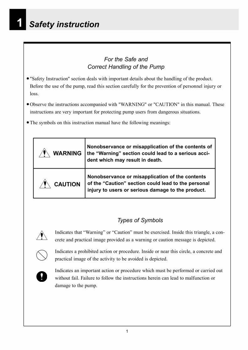
1
1 Safety instruction
Nonobservance or misapplication of the contents of the ldquoCautionrdquo section could lead to the personal injury to users or serious damage to the product
WARNINGNonobservance or misapplication of the contents of the ldquoWarningrdquo section could lead to a serious acci-dent which may result in death
CAUTION
Types of Symbols
Indicates that ldquoWarningrdquo or ldquoCautionrdquo must be exercised Inside this triangle a con-crete and practical image provided as a warning or caution message is depicted
Indicates a prohibited action or procedure Inside or near this circle a concrete and practical image of the activity to be avoided is depicted
Indicates an important action or procedure which must be performed or carried out without fail Failure to follow the instructions herein can lead to malfunction or damage to the pump
For the Safe and Correct Handling of the Pump
Safety Instruction section deals with important details about the handling of the product Before the use of the pump read this section carefully for the prevention of personnel injury or loss
Observe the instructions accompanied with WARNING or CAUTION in this manual These instructions are very important for protecting pump users from dangerous situations
The symbols on this instruction manual have the following meanings
2
Safety instruction
bull Qualified operators only This product must be operated by users with a full understanding of the pumps Person who has not
leaned about the pumps should not operate this productbull Turn off the power supply Dismantlementassembly without turning off the power supply may cause an electrical shock Before
engaging on any maintenance and inspection work be sure to turn the power supply switches off to stop the pump and the related devices
bull Risk of electric shock This pump is supplied with a grounding conductor and grounding-type attachment plug To reduce the risk
of electric shock be certain that it is connected only to a properly grounded grounding-type receptaclebull Wear protectors Getting wet with or coming in contact with the hazardous chemical liquid such as acid and alkaline
solution could lead to a serious injury Wear protective clothing such as a protective mask gloves and goggles according to the handled liquid during the work
bull Terminate operation Upon becoming aware of any dangerous signs or abnormal condition during operation terminate the
operation immediately and start it from the beginning againbull For specified application only The use of a pump in any application other than those clearly specified may result in the injury or the
damage to the pump Use the pump in accordance with the pump specificationsbull No modification Do not modify the pump Otherwise a serious accident may result We are not responsible for any
accidents or losses caused from any modifications to the pump without the first obtaining permission or instructions from Iwaki
bull Humid place prohibited This product is not water-proof construction If the pump is used at a highly humid place or the place
where liquid can splash the pump electrical shock or short-circuit may happenbull Do not step on tank
Stepping on tank the tank may fall down and cause personal injury or a loss Never step on tank
bull This pump has been evaluated for use with water only The suitability of this pump for use with liq-
uids other than water (such as acid and alkaline) is the responsibility of the user
bull Do not touch pump during the operation
Temperature of the pump surface during the operation is high Do not touch pump with the bare hands
bull Specified power only
Do not apply the voltage which is not specified on the nameplate to the product Otherwise damage or
fire may result Only the specified power source must be used
bull Pay attention to dry running
Do not run pump dry more than 30 minutes otherwise the screws of the pump head may loosen This
results in liquid leakage Secure the working condition for the prevention of dry running
Electrical Shock
No Remodeling
Wear protective gear
Prohibited
Prohibited
Caution
Do not wet or dampen
Caution
WARNING
CAUTION
Prohibited
Prohibited
Caution
Electrical Shock
3
Safety instruction
Prohibited
Prohibited
bull Do not wet or dampen If the electric parts or the wiring get wet by the unintentional liquid spillage a fire or an electrical
shock may occur and the controller breaks Install the system in a place free from liquid spillage or leakage Do not engage in wiring work with the wet hand
bull Do not operate pump with valves close Liquid spillage or the rupture of pump headpiping may occur due to an abnormal pressure rise Do
not run the pump with valves closebull Pay attention to the reciprocating motion of diaphragm Do not put any objects in bracket hole during the pump operation Diaphragm reciprocates inside the
bracket The contact with the object can cause malfunction bull Do not cover the pump body with cloth
The temperature inside the pump body rises when the pump body is covered This could lead to a fire Secure ventilationbull Prevention against freezing
Pump head may suffer damage due to freezing at below zero Be sure to remove the liquid from the pump body and piping after the use of pump
bull Ventilation Poisoning may result in the operation handling the toxic or odorous liquid Ventilate the operating site sufficientlybull Prevention of the spill-out accident Protective measures should be taken against any accidental spill-out as a result of unexpected damage
to the pump or the related pipingbull Damaged pump Never operate the damaged pumps The damaged pumps may cause leakage or electrical shockbull Handling of power cable Use of the defective or damaged power cable may result in a fire or electrical shock Do not scratch
modify or tug the power cablebull Install an earth leakage breaker (option) The operation of this product without using an earth leakage breaker may cause an electrical shock
Purchase an optional leakage breaker and install it in the systembull Frequent ON-OFF operation should be made via the STOP function with the signals to the STOP terminal In case
the ON-OFF operation without STOP function the maximum number of the ON-OFF must be 6 per an hourbull Follow the instruction manual Replace the consumable parts by following the descriptions in the instruction manual Do not disas-
semble the pump beyond the extent shown on the instruction manualbull Limited operating site and storage Do not install or store the pump in the following places where Flammable gas or material is used or stored The ambient temperature is extremely high (40 digC or higher) or extremely low (0 digC or lower) The pump is exposed to the direct sunlightbull Disposal of used pump The used or damaged pumps should be disposed of in accordance with the relevant local laws and
regulations (Consult a licensed industrial waste products disposing company)bull Loose fixation of mounting bolts can lead to liquid leakage
Be sure to tighten all the hex sock bolts (Number of bolts is 6 or 8) before an initial operation Periodically check all the bolts tight and re-tight as necessaryTightening torque is 255Nbullm Have the bolts tight gradually and diagonally
Caution
Prohibited
Caution
Caution
Caution
Caution
Prohibited
Electrical Shock
Do not wet or dampen
Caution
4
2 Product outline
2 Principle of operationIWAKI electromagnetic metering pump EH-F model is the diaphragm type metering pump of which dia-phragm is directly driven by the electromagnet force and consists of a pump head a driving unit and a control unit Reciprocating movement is made by the force of spring and the electromagnet generated by the pulse current coming from control unit The reciprocating movement is transferred to the diaphragm which is connected to a plunger to make volumetric change in pump chamber Pumping effect is obtained by the volumetric change and by the effect of valves which are placed in a pump head
Stroke lengthadjusting knob
Control unit
Driving unit (Pump body) Plunger
Pump head
Valve
Diaphragm
1 Unpacking and inspectionFor the purpose of confirming that the prod-uct delivered corresponds with your order after unpacking check whether-
bull The model flow rate discharge pressure andrated voltage on nameplate is as you ordered
bull All the accessories are in place Refer topage 52 Accessories
bull There is no transit damage and no loose boltnutbull Regarding union connection and flange connec-
tion types union sockets and flange units are packed apart from pump body
Note We ship the products with the greatest care but if you find any defects contact us or your nearest dealer
Handled liquid
5
Product outline
3 Model identification
1 Pump
EH - F 55 VC C6 - 10U -
Series code Driving unit code (Average power consumption) F 100 W Diaphragm effective diameter35 35 mm 45 45 mm 55 55 mm 70 70 mm
Wet end material
PartCode Pump head Valve O ring
Valve seat Gasket Diaphragm
VCPVC
Ceramic FKMPTFE
PTFE+
EPDM(Non wet end)
V6 SUS316 EPDMPC GFRPP Ceramic FKM
Special specification code01 - 99 Non standard material non standard connection or so
Connection hose diameter codeCode Connection hose dia
C6 empty 38 times empty 12C7 empty 58 times empty 34C8 12NPTC12 ANSI 150LB 12
Supply voltage codeCode Supply voltage10U AC115 V (with a plug)20U AC230 V (with a plug)
Allowable voltage range FrequencyAC1035 V - 1265 V 50-60 HzAC207 V - 253 V
Material code PVC Polyvinyl chloride PTFE Poytetrafluro ethylene (Teflon) FKM Fluor rubber (Acid resistant Viton) GFRPP Glass fibber reinforced polypropylene EPDM Ethylene propylene rubberNote Regarding handled liquid acid and alkaline solution is transferred depending on wet end material
Acid solutionAlkaline solutionAcid solution
6
Product outline
2 Controller
EHC - F 10U -
Controller unit type for EH-F EHC Controller EH pump driving unit code
Supply voltage code
Special specification code 01~99 Special specification
Code Average power consumptionF 100W
Code Supply voltage10U AC115V20U AC230V
Allowable voltage range FrequencyAC1035V - 1265V
50-60HzAC207V - 253V
7
Product outline
4 Parts name
1 Pump parts
Pump headLock screw
Driving unit
Control panel
Control unit
Stroke lengthadjusting knob
Socket cord
MAN DIV MULT ANAR V
OVER P12 LOCK Err SET
spm
mA
LED lights orange when Pre-STOP signal comes from level sensor or lights redly when STOP signal comes
Screen indicates operation states and setting values in figures and letters
StartStop key is used tostartstop pump operation
EXT keyis used to start pumpingin EXT operation mode
ON lamp lights as turning on power and blinks synchronously with each stroke
Up key is used to increase the setting values and to change the setting items Pressing Up and Down key at once can have the pump running at full spm
Down key is used to decrease the setting values or to change the setting items Pressing Up and Down key at once can have the pump running at full spm
2 Control unit
8
Product outline
5 Specification
1 Pump specification
2 Control unit specification
Operationmode
MAN (Manual operation) 1 - 240 spm
EXT
DIV (Pulse dividing) 1 - 9999MULT (Pulse multiply) times1 - 9999ANA R (Analog rigid) 4-20 0-20 20-4 20-0 mAANA V (Analog variable) 2 points in a range of 00-200 mA 0 - 240 spmEXT mode consists of the above 4 modes
Display
LCD 14 seg 5 digits spm Operational states and Settings
LEDON Green Lights as turning power on
Blinks synchronous with each strokeSTOP OrangeRed Lights orange when Pre-STOP is activated or lights redly when STOP is activated
Operation 4 keys STARTSTOP EXT UP DOWN
Control function
STOP Pump keeps running when Pre-STOP is activated or stops when STOP is activated
Self priming Pump operates at full speed when both Up and Down keys are depressed together
Key lock Lock and release key padsBuffer memory ONOFF setting is changeable (Initial setting is OFF)
InputPulse No-voltage contact Maximum 100 HzCurrent Range of DC0 - 20 mA (Input resistance 200 Ω)Level sensor Potential free contact or open collector 2-step contact
Output Photo MOS Relay ACDC 24 V 01 Aspm synchronous output The maximum input pulse frequency is 100 Hz however the maximum frequency is variable
depending on the setting of anti-chattering On-time of pulse requires 5 ms or more when ST 05 is selected
5060Hz
ModelsMax discharge
capacitymlmin(GPH)
Max discharge pressureMPa(PSI)
Stroke speed variable range
spm
Stroke length variable range
mm()
Average power
consumption
W
Masskg
EH-F 1 - 240 09 - 225(40 - 100) 100
45 750(119) 07(102)55 1200(190) 045(65)
16
70 2000(317) 03(44)
35 500(79) 10(145)
Note 1 Performance is obtained by pumping clean water at ambient temp at a rated voltage2 Discharge capacity is the value at max discharge pressure (100 stroke length 100
stroke rate) When discharge pressure is low pump discharges liquid much more than the discharge capacity shown above
3 Permissible ambient temperature 0 ~ 40 deg C 4 Permissible liquid temperature VC V6 0 ~ 40 deg C PC 0~60 degC 5 Permissible voltage fluctuation Within plusmn10 of the rated voltage6 Ask us or our distributor for special cases such as transferring slurry liquid
9
Product outline
6 Operational function
1 Manual operation and keys are used to set the number of strokes between 1 and 240 spm The pump startsstops
operation by pushing START STOP key The number of strokes is adjustable in the both pump states of running and stop
ON
ON
OFF
ON ON
STARTSTOP key
Operation
Stop
Operation
Pump operation
External signals
ON
OFF
Pump operation
1 2 3 4 1 2 3 4 1 2 3 4
Set value 14 in dividing operation
2 Pulse dividing operationIn this mode pump runs in the dividing operation for external pulse signals Dividing ratio is variable within the setting range between 9999 1 and 1 1 The upper limit of the number of strokes in the pulse dividing operation is equivalent to the maximum number of strokes in manual operation When the input signals over the upper limit stroke speed is incoming the residual signals can be stored up to 65535
External signals
Pump operationON
OFF
Set value 4 in multiply operation
1 2 3 4 1 2 3 4 1 2 3 4
3 Pulse multiply operationIn this mode pump runs in the multiply operation between 1 and 9999 times for an external pulse signal and stops automatically The number of strokes in the pulse multiply operation is equivalent to the number of strokes in manual operation The incoming pulse signals during the multiply operation motions are cancelled and are stored up to 65535
10
Product outline
4 Analog control operation ANA R(analogue rigid) mode
Pump operates within the range of 0-240 spm in proportion to the external signals between 0-20 mA4 (4-20 20-4 0-20 20-0) patterns are provided and the pump operates within 0-240 spm in proportion to the external signals in each patternIn the 4-20 or 20-4 pattern a breaking detective function becomes active automatically The function stops the pumping operation below 4 mA And an error indication DISCN blinks on the display of con-trol unit When this function is active check wiring This function can be released with STARTSTOP key
42
3
1
Num
ber o
f stro
kes
240
0 4 20
(spm)
Analog input(mA)
Conditions
The left graph is in the following patterns 4 - 20 20 - 4 0 - 20 20 - 0
240220
60
0 6 2017
(spm)
Analog input (mA)
P1
P2
Num
ber o
f stro
kes
Conditions
The left graph is in the following settingP 1 = 6 mA 60 spmP 2 = 17 mA 220 spm
ANA V(analogue variable) modePump operates within the range of 0-240 spm in proportion to the external signals between 0-20 mA Setting 2 points can draw a straight line Depending on the position of the 2 points 0 spm may not come at 0 mA in some cases When the stroke speed could become over 240 spm at some mA due to the set-ting pump speed is limited to 240 spm
11
Product outline
7 Control display instruction
1 Control unit
ON STOP
EXT
EH-F ControllerSTARTSTOP
DIVMAN
OVER P1 2 LOCK Err SETmA
spmMULT ANAR V
Manual operation indication (MAN)shows pump is in manual operation
indicationshows pump is running for self-priming at maximum stroke speed and calls userrsquos attention
mA indicationappears when setting amperage in EXT setting mode for analog control operation
SET indcationappears in user mode and EXT setting mode
Stop indicationappears during Pre-STOP or STOP signal input
Stroke speed indication appears when displayshows stroke speed
Pulse dividing indication (DIV)shows pump is in pulse dividing operation or pulse dividing ratio is being set
Pulse multiply indication(MULT) shows pump is in pulse multiply operation or pulse multiply ratio is being set
Display shows operational state and set values in figures and letters
STARTSTOP keyis used to startstop pump operationThis key is also used to confirm each set value in set modes and used to move to wait mode
EXT keyis used to start pump operation in EXT operation modes
Over indicationlights when incoming signals are surplus to 240 spm in EXT operation
P1 and P2 indicationsappear when 2 points(P1 P2) are set in ANA V(analog variable) mode for analog control operation
Lock indicationappears when keys are locked
ON lampappears as turning on power and blinks synchro-nously with each stroke
Error indicationappears when an error occurs
Analog control operation indication (ANA R ANA V)ANA R indicates pump is in analog rigid operation or setting mode ANA V indicates that pump is in analog variable operation or setting mode
Down key is used to decrease the setting values and to change the setting items Pressing Up and Down key at once can have the pump running at full spm
Up key is used to increase the setting value and to change the setting items Pressing Up and Down key at once can have the pump running at full spm
12
Product outline
2 Typical indications
3 Warning indications
Indications Show
Pump is operating in the manual operation modeThe display shows the set spm
Pump is operating in the analog control mode(ANAV) of the EXT operation Display indicates 168 spm
The stroke speed is being set while pump is operating in the multiply operation(MULT)
Pump is being stopped via STOP input while operating in the dividing operation(DIV)
MAN spm
LOCK SET mA
MAN ANA V spm
MULT
SET
DIV spm
Indications shows
Key lockAll the key operation can be ineffective in order to prevent any per-son other than user from operating the pump This function can be active by pressing STARTSTOP key for 5 seconds in any pump states and LOCK indication appears Key lock function can be released by pressing STARTSTOP key for 5 seconds when LOCK indication appears on the display
The left indication appears when input signal is below 4 mA with the 4-20 or 20-4 pattern in ANA R (Analog rigid) mode In this state pump is under suspensionBy pushing STARTSTOP key once this error is released and the mode moves to waiting mode Check wiring and signals
OVER indication appears when incoming signals are surplus to 240 spm in EXT operation
MAN spm
LOCK SET mA
ANAR
Err
spm
MAN spm
OVER
13
Installation
1 Before installation
Working without disconnecting the power supply may cause an electrical shock Before engaging upon any working procedures involving the pump be sure to turn the power supply switches off to stop the pump and the related devices
Upon becoming aware of a dangerous sign or an abnormal condition while engaging on the installation terminate the work immediately and start it from the beginning again
Do not operate the pump on the voltage which is not specified on the nameplate Failure to do so may result in damage or a fire Be sure to earth the pump
Do not place any dangerous materials or flammable objects near the pump for the sake of safety
WARNING
CAUT ION
1 Dropping the pump or subjecting it to a strong impact may result in the faulty performance Handle the pump with care Do not use the damaged pump for the prevention of the electri-cal leak or shock
2 When installing pump avoid the places where the pump is exposed to the direct sunlight the ambient temperature is above 40 digC or the relative humidity is above 85 Though the pump has a simple waterproof and dust-proof structure it is recommended to protect the pump with a cover when installing it outdoor
3
Installation
14
3 Select a level floor and use the four M6 bolts to firmly anchor the pump so as not to allow any vibration If the pump is inclined the discharge amount may decrease considerably
4 Pump should be installed in a well-ventilated place in summer and free from freezing in win-ter
6 Place the pump as close to the suction tank as possible realizing a flooded suction system (It is recommended the pump should be located lower than the suction-side tank)
7 If the pump is used to feed some liquid that gen-erates air bubbles easily (sodium hypochlorite hydrazine solution etc) the system must be positioned in a cool dark place away from direct sunlight If a tank is installed realize a flooded suction system
5 Select the installation site convenient for the future maintenance and inspection
2 Precaution for piping Piping vibrates due to the pulsation from pump Piping should be supported in order to prevent the vibra-
tion Install an air chamber or an accumulator to reduce the pulsation Ask us for further information Be careful not to have hose bend when arranging tubing It is recommended to arrange the short piping as much as possible The longer piping length the more
pressure drops and can exceed the allowable pressure of pump and can cause the over feed phenom-enon
It is recommended an automatic air bleed valve or a pressure relief valve should be installed in order to release the pressure of discharge piping for maintenance
It is recommended to install a relief valve on the discharge side piping that releases pressure automati-cally
Install a pressure gauge on the discharge side piping in order to measure the pressure inside the piping When installing EH-F pump with the flange connections or the union connections be sure to have the
connections on the discharge side fixation on wall pillar or the frame of equipment for the prevention of vibration Make sure that the piping is fixed as well
CAUTIONIncomplete fixation of pump and piping can lead to the damage to these products Significant vibration often results from the incomplete support for the discharge side connection of pump In case the direct support for the flange or union connection can not be secured try to support pump close to the discharge connection as much as possible
15
Installation
Check valve
Air bleedValve
Discharge hose
Pump
Tree way joint
Accumulator
Drain valve
Discharge valve
Back pressure valve
Pump
Suctionvalve
Air bleed valve
Airchamber
Pressure gauge
Relief valve
3 Piping1 Recommended piping drawings
Arrange piping to meet the suction and dis-charge requirement Especially pay attention to piping arrangement in case of handling the slurry which has settling property
Installation
16
Hose
Hose stopper
Fitting spacer
O ring
Fitting nut
Place hose stoppers with R surfaceface to face with fitting spacer
Hose
Hose stopperFitting spacer
O ring
Fitting nut
Fitting
Suction port
Pump head
2 Piping arrangement1 For hose connection first fit a fitting nut and then a
hose stopper and a fitting spacer in the last place If the hose stopper is not fitted properly leakage may occur and suction amount may decrease
The hose end should be secured by a hose stop-per Insert a hose end into a fitting spacer via a fitting nut and a hose stopper Then squash the hose end between the hose stopper and the fit-ting spacer Finally screw the fitting nut in
The hose stopper should be placed with its R surface face to face with the fitting spacer An incomplete hose stopper fixation or a reverse hose stopper placement can lead to leakage or insufficient suction
CAUTIONReverse hose stopper placement can dam-age hose
Fitting nut is made of plastics The fitting nut may break when it is tightened excessively
If attached hose is not long enough prepare a substitute hose such as chloroethene braided hose and polyethylene hose with a suitable bore to the hose fitting spacer
CAUTIONIt is very dangerous to attach the different size hose It may come off
Insert the fitting spacer into hose as deep as possible If the insertion is not enough hose may come off and leakage may result
Be careful not to lose the attached O rings Leakage or suction failure may result without an O ring
2 Hose connection tends to loose if liquid or ambient atmosphere is higher than normal temperature Re-tighten the fitting nut properly after starting opera-tion Be careful not to tighten the nuts too much
3 When fitting the hose again after detaching it for maintenance cut the end of hose off about 10 mm and insert it
17
Installation
4 Check valveEH-F35 45 (VCV6PC) types are attached with a check valve Fit the check valve to piping in the fol-lowing cases
1 The suction side liquid level is higher than the dis-charge side liquid level (Fig A) When injection point is below the liquid level of suction side at atmospheric pressure
2 The suction side pressure is higher than the discharge side pressure (Fig B)
3 The discharge side liquid level is higher than the suction side liquid level but the differential height between both liquid level is 5 m or below (Fig C)
4 The loading pressure of piping resistance and dis-charge head to the pump is under 013 MPa
Suction side Discharge side
Figure A
Figure B
5m
Figure C
To chemical tankor vessel
Remove check valve
3 Piping for bleedingPrior to bleeding disconnect hose and point a hose end at a suction tank or vessel Remove a check valve if it is attached on the discharge side piping
18
Installation
R12
Oslash12
5 Check valve mounting1 Tap the female thread of NPT12 at an injection
point Check valve is provided with the male thread of R12 Cut off the unused portion to fit it on a pip-ing
2 Apply seal tape on the threaded portion of the check valve and screw it in the injection point Pinch the check valve body lightly with a spanner and tighten it for easy mounting
3 When fitting a hose into a check valve with the check valve on main pipe tighten the fitting nut holding the check valve body by hand
4 Cut the end of check valve(empty 12) accordingly when mounting it in a small pipe It is recommended the end of the check valve comes at the centre of pipe bore
It is recommended to mount a check valve via a valve for maintenance Provide NPT12 female thread and screw it in Valve should be resistant to the chemical liquid in use
Valve
Check valve
Check valve body
Apply seal tape
Fitting nut
Pipe
Cut the end nozzle offif it is too long compared topipe bore
6 Flange connection and union connection1 Flange units and union sockets are packed apart from pump body Fit the flange units or the union sockets to
pump body before use Refer to the following figures2 Secure the sealing by fitting O rings to each connection
CAUTIONWhen mounting flange units or union sockets to pump body be careful not to allow O ring to get out of the groove Especially pay attention to the O ring on the groove on suction side
3 Fix the flange units or the union sockets to the pump body by tightening fitting nuts In this case first tighten the fitting nuts by the hand and then re-tighten it by 90 degrees with a spanner
CAUTION
Fitting nut is made of plastics The fitting nut may break when tightened excessively
Flange connection type
19
Instillation
Flange
Flange
Fitting nut
O ring
O ring
Elbow
Pump body
Fitting nut
Drain
Discharge
Air chamber
7 Accumulator and air chamber mountingInstall an accumulator or an air chamber on piping for the prevention of the vibration from the pulsation of pump discharge hose
20
Installation
8 Piping (General notes)1 Keep piping short and less bends Do not make the projections where air can remains
2 Support piping to avoid having the pump subject to the piping weight especially when wet-end mate-rial is made of PVC
3 In case of transferring the slurry which tends to settle do not make U shape on piping A drain plug is required at the lowest portion of piping as well
4 In case of transferring the viscous or toxic liquid or the liquid which tends to settle provide the piping for cleaning for the purpose of maintenance
5 In case of transferring the high temperature or low temperature liquid the telescopic motion of piping from temperature variation should be taken into consideration
6 Select pipe materials based on a through examination of the corrosive resistance and the estimated pressure applied to piping
7 Do not allow any adhesive agent to get in pump when connecting PVC-made pipe on the discharge side piping
8 Clean the inside of piping before installing pump in it
9 A relief valve is required to protect pump and piping Install a relief valve on the discharge piping near the pump
9 Suction piping1 Regarding suction piping a flooded suction system should be realized The bore of suction piping is
recommended to be larger than that of pump suction port
2 Each joint of suction piping needs to be mounted carefully in order to prevent air from coming in Air influx into piping may cause discharge performance failure and instability
10 Discharge piping1 Mount a relief valve on the discharge piping near pump A discharge valve should be mounted beyond
the relief valve
2 The pressure resistance of discharge piping should be higher than the set pressure of relief valve Mount each joint carefully
21
Installation
4 Electrical wiring
1 Power cord connection
Electrical works and the handling of power source must be done by qualified person
Do not operate pump with the wet hand
Make sure that power is not turned on while working on wirng
Do not dismantle electronic circuit
Electronic circuit may be broken Never apply other voltages than a rated voltage
WARNING
CAUT ION
High power equipment
CAUTION Avoid sharing a power source with a high
power equipment This can lead to the fail-ure of the electronic circuit of control unit due to extremely large surge voltage
The noise from an inverter can cause fail-ure
22
Installation
P
Surge absorption element
PNoise cut transformer
CAUTION
2 Wiring procedure
Electronic circuit of control unit may be failed by extremely large surge voltage Do not use the pump near to the high power equipment of 200V or more which may generate large surge voltage If the use of high power equipment is inevitable take either of the following measuresa Install a surge absorption element such
as varister with 2000A or more durability on the power point
b Install a noise cut transformer
CAUTION
Only qualified operatorsservice staff should be in charge of the related electrical arrange-ment and control of the power source Failure to observe this instruction may result in injury to person or damage to assets
Never connect wires while power is turned on otherwise an electrical shock or a short-circuit of controller may result Be sure to turn off power before wiring
Internal circuit is still electrified right after turning off power Take 1 minute or more to start wiring
Do not band a power cable either electrical wires or relay output wires
Earthing wire is equipped with a jumper pin Keep the jumper pin equipped in use
Do not combine the EXT or STOP signal line with a power cord or a power cable Do not com-bine power source line with the EXT or STOP signal line by a concentric cable (5 wires cable or so) Otherwise noise come about through EXT and STOP wires due to the induction effect from power cable and it may results in wrong operation or the failure of pump
Regarding frequent ON-OFF operation it is recommended to stop pump thorough STOP input terminal but not by connecting or disconnecting power source When connecting and discon-necting power cord can not be avoided it should be within 6 times an hour
23
Installation
Procedure to connect the signal cordUse DIN connector of five poles and four polesThe following connectors made by Binder in Germany are recommendedAsk IWAKI for the detail of Binder connector 5 poles 713 series 99-0436-10-05 for input signal 4 poles 715 series 99-0430-15-04 for level sensor
The following connector made by Hirschmann in Germany is recommendedAsk IWAKI for the detail of Hirschmann connector 4 poles GDS307 for output
The following procedures are based on the connector made by Binder and HirschmannIf a similar connector is used the wiring should be made according to the instruction manual of the manufacturer of connector
In case of Binder connector(1) Dismantle the connector and pass the wire through it Outer diameter of the cable should be oslash4-6
Using the different cable in diameter the connector can not be sealed properly
(2) Strip the cable ends and insert wire to the appropriate positions and connect them with screwsThe maximum allowable cross section of the wire is 075mm2
(3) After connecting the wire assemble the connector securely Slightly pull the cord to confirm that the cord connection is secured Perfect sealing can not be obtained unless the cord connection is loose
24
Installation
In case of Hirschmann connector(1) Dismantle the connector and pass the wire through it Insert a minus screw driver into the place shown by
ldquoLIFTrdquo and lift it up Outer diameter of the cable should be 35-6 mm Using the different cable in diam-eter the connector can not be sealed properly
(2) Strip the cable ends and insert wire to the appropriate positions and tighten them with screwsThe maximum allowable cross section of the wire is 075mm2
(3) After connecting wire assemble the connector securely Slightly pull the cord to confirm that the cord connection is secured Perfect sealing can not be obtained unless the cord connection is loose
Terminal position
NA Not Applicable
Connection of level sensorThe controller corresponds to two stage level sensor Connect the pre-alarm signal to Pre-STOP and the alarm signal to STOP When the pre-alarm signal comes in the orange lamp lights but the pump does not stop When a contact type is used connect wires to STOP and COM2 For open collector output level sensor Pay attention to the polarity Pre-Stop and STOP are plus (+) and COM2 is minus (-) (Max charged voltage 5V Current 18mA) For contact output level sensor Use the one designed for electronic circuit and the minimum applicable load of 1mA or less
Connection inside connector 1 STOP 2 Pre-STOP 3 Free 4 COM2
1
2
3
4 CLOSE
ON
PUMP
Level Sensor(STOP)
OPEN
Pulse
COM
+12VDC
NA
ANA(4-20)
Pre-STOP
STOP
COM
NA
OUT
25
Installation
Stop functionStop function is the function to stop the pump by the external signal Connect the wires to STOP and COM2 in the same way as the level sensor connection
CAUTION
Frequent stop and start of pump should be done by using STOP function (ON and OFF of STOP terminal) If you can not use STOP function and are forced to operate pump by turning OFF and ON of power source ON and OFF of power source should be limited to six times an hour
Pulse signal inputPulse signal input is used when the pump runs in the DIV or MULT of EXT modeDIV means dividing and MULT means multiply In case of open collector signal Pay attention to the polarity Pulse is plus (+) and COM1 is minus (-) (Max charged voltage 5V Current 18mA) In case of contact signal Use the one designed for electronic circuit and the minimum applicable load of 1mA or less
Connection inside connector 1 Free 2 Pulse 3 Free 4 12VDC 5 COM
3
2
4
15
Analog signal inputAnalog signal input is used when the pump runs in ANAR or ANAV of EXT modeANAR means analog rigid and ANAV means analog variable
Connection inside connector 1 ANA 2 Free 3 Free 4 Free 5 COM
3
2
4
15
26
Installation
Output signalOUT Photo MOS relay outputStandard is output synchronous with stroke Output is activated synchronous with each pump stroke
Connection inside connector 1 OUT 4 OUT
OUT 1
2
34
Surge voltage The electronic circuit of the control unit may be affected by excessively high surge voltage Do not operate the pump near the high-power elec-trical equipment of 200V or above that generates high surge voltage Under unavoidable circumstances take either of the following measures(1) Use a surge absorbing element (such as a
varistor with the surge resistance of 2000A or more) at the pump power supply connection
(2) Use a noise-cut transformer
Surge absorbing element
Noise-cut transformer
1 Preparation for pump operationBefore pump operation check that
bull Liquid tank is filled enough Supply liquid if it is less than the required levelbull There is no liquid leakage or congestion due to breakagebull Both suction and discharge side valves are openedbull Pump is connected to the predetermined power source correctlybull Electrical wiring is correct and there is no possibility of a short circuit or current leakage
2 BleedingBleeding is a process to eliminate the air inside the suction-side piping Be sure to carry out an air elimi-nation prior to initiating the pump operation after replacing the liquid inside a tank and after a long peri-od of storage Air gushes together with chemical liquid when carrying our bleeding For safety reasons first turn the end of a bleeding hose to a tank or a container
CAUTION
Some liquids may cause skin trouble or affect the quality of mechanical parts Wipe off chemi-cal liquid immediately when they splash on the hand or mechanical parts
27
Operation
1 Pump Operation
WA R N I N G Wear protective clothing
Wear protective clothing such as a protective mask safety gloves or so when handling chemical liquid
Do not operate pump with a discharge-side valve completely closed Operating the pump with the discharge-side valves fully closed may cause the liquid spillage or
the extremely high pressure inside the pump or the discharge-side pipingtubing This could lead to a piping burst Be sure not to operate pump with the discharge-sides valve closed
CAU T I O N A long time dry running (longer than 30 minutes) may cause the pump overheat and it could lead
to the deformation of the pump unit consists of a pump head and valve cases or so or may loosen the pump head fitting and result in liquid leakage
If the hex socket cap bolts on a pump head are loosened liquid leakage may resultBe sure to fasten all the 6 or 8 hex socket cap bolts tightly before starting the initial pump opera-tion And periodically check the looseness of the bolts on the pump head and retight the bolts as necessary
bull Tightening torque255NbullmTighten all the bolts diagonally applying equal tightness
If electric wiring gets wet due to accidental liquid spillage fire or electrical shock may occur Never get it wet When the electric wiring gets wet turn off power and wipe the liquid away
A frequent ON-OFF operation should be conducted by using STOP function(ON - OFF signals to STOP terminal) In case the STOP function is not available for the ON-OFF operation the ON - OFF operation by turning onoff power should be limited to six times an hour
4
28
3 Procedure for bleeding
Check valve should be removed
To tank or drain pan
100
75
50
25
0 25 50 75 100
(Fixed stroke length)
Stroke length adjustment
240spm
180spm
120spm
Flow
rate
Operation
[1] Extend the tube connected to the discharge-side fitting nut of pump to a chemical tank or a drain pan Then start pump operationbull Remove a check valve if it is installed on dis-
charge-side
[2] Operate the pump for about 10 minutes to eliminate air completely
[3] When the air in pump head is completely eliminated and liquid is replaced return the discharge-side tube to the regular tubing position
[4] Finally make sure there is no leakage in any section
4 Discharge capacity adjustmentDischarge capacity can be adjusted by both the stroke length adjustment and the stroke rate adjust-ment but basically adjust it via the stroke rate adjustment Stroke length adjustment is an auxiliary way to cover the range where the stroke rate adjustment can not reachPay attention to the following for correct procedure
Stroke rate adjustment(1) For some liquids which diffuses gas such as sodium hypochlorite and hydrazine solution adjust discharge capac-
ity by means of the stroke rate adjustment with the stroke length about 100 Gas lock may occur if the stroke length is set to short
(2) When the back pressure on discharge side is high adjust discharge capacity by the stroke rate adjustment with the stroke length about 100
(3) In case reaction is greatly influenced depending on the discharge capacity per pump shot in the application of neutralization or titration adjust discharge capacity by the stroke rate adjustment with the shortened stroke length and reduce the discharge capacity per shot
1 Discharge capacity adjustment procedureAppropriate stroke length and stroke rate are decided on the pump operating condition and liquid characteristics Following ways are recommended for proper calibration
(1) Set stroke length at 100 and roughly adjust discharge capacity by adjusting stroke rate
(2) Measure discharge capacity(3) If the measured capacity is below the wanted value
increase the stroke rate and measure again the dis-charge capacity
(4) Adjust stroke length for the fine adjustment of discharge capacity(5) Determine a discharge capacity at the last and confirm the wanted capacity is discharged
CAUTION
29
100
75
50
25
0 60 120 180 240spm
Fixed stroke length
Stroke rate adjustment
Flow
rate
Screw driverOPEN
LOCK
100
75
50
25
0 25 50 75 100
Fixed stroke rate
Flow
rate
Stroke length adjustment
Operation
2 Stroke rate adjustmentStroke rate is adjusted by the key operations of control unit Control the plunger stroke rate per minute from 1 to 240 spm via control unit
3 Stroke length adjustmentStroke length adjustment knob is locked with a screw Loosen the screw before adjustment and lock it afterwards
(1) Turn on pump and adjust the discharge capacity by turning the stroke length adjusting knob while pump is running
(2) The left graph shows the relation between stroke length and discharge capacity The maximum dis-charge capacity is shown on the name plate
bull The usage between 40 and 100 is practi-cal
Do not turn the stroke length adjusting knob when pump stops
CAUTIONBe sure to tighten the screw on the adjust-ment knob after an adjustment The knob may rotate unintentionally due to a loose fixation This may result in the fluctuation in a discharge rate
30
Mode ParameterDefault value
Setting range Step
Manual operation Stroke speed 240 1-240DIV setting Dividing ratio frasl 1 1-9999
MULT setting Multiply ratio times1 times1-9999ANA R setting 4-20 4-20 20-4 0-20 20-0
ANA V setting
P1 amperage 40 00-200P1 stroke speed 0 0-240P2 amperage 200 00-200P2 stroke speed 240 0-240
User setting
EXT operation ANA V DIV MULT ANA R ANA V
Anti-chatteringMECH MECH ELECST05 ST05 ST20 ST50FT01 FT02 FT04
Buffer memory MEM-N MEM-N MEM-Y
111-
011
011
2 Control unit operationEH-F type pump is controlled by means of setting or changing the setting values of the controller Control functions are various at each operation mode Read this section carefully before operation
Default parameter values
5 Full operationPut pump in use after bleeding and adjusting discharge capacityPump runs in manual operation or in accordance with the setting of control unit
6 Manual operationStarting pump After turning on power ON lamp (Green) appears and display shows WAIT mode For
the first time to turn on power MAN lamp appears and pump starts after pushing STARTSTOP key once
Stop pump Push STARTSTOP key to turn off MAN lamp and stop pump Pump starts and stops every time STARTSTOP key is pressed
7 EXT operationRefer to the next section of 2 Control unit operation
8 Shout down When pump will not in use for a long time (one month or more)
Run pump with clean water about 30 minutes in order to clean the wet-end parts and the inside of pip-ing before storage
When re-starting pump after a long time storage If pump dose not suck up liquid clean valve sets and remove the sticking foreign matters Carry out an air elimination and adjust discharge capacity when air stays inside pump head Refer to page 28 3 Procedure for bleeding
Operation
---
-
31
AN
A V
(Ana
log
var
iabl
e)
DIV
(Pul
se d
ivid
ing)
MU
LT(P
ulse
mul
tiply
)A
NA
R(A
nalo
g ri
gid)
SE
TS
ET
Use
r mod
e
EX
T m
ode
sele
ctio
n
EX
T
EX
TE
XT
EX
TE
XT
EX
T EX
T
EX
T
EX
T
EX
T
EX
T
EX
T
EX
T
EX
T
EX
T
EX
T
EX
T
EX
T
3 sec
onds
or m
ore
Wai
t mod
e
Set
ting
of fi
xatio
n pa
ttern
EX
T m
ode
Man
ual o
pera
tion
Set
ting
of s
troke
num
ber
AN
A R
(Ana
log
rigi
d)M
ULT
(Pul
se m
ultip
ly)
DIV
(Pul
se
div
idin
g)
AN
A V
(Ana
log
var
iabl
e)
anti-
chat
terin
gse
tting
dis
play
Setti
ng o
f div
idin
g ra
tioS
ettin
g of
cou
nt n
umbe
r
Curre
nt va
lue of
P1
Stro
ke nu
mbe
r of P
1
Curre
nt va
lue
of P
2
Stro
ke nu
mbe
r of P
2
EX
T O
pera
tion
Dis
play
EX
T se
tting
mod
e
Buf
fer m
emor
yse
tting
dis
play
Pow
er O
N
spm
MA
Nsp
m
spm
DIV
DIV
SE
TS
ET
MU
LT
MU
LTsp
mA
NA
V
spm
AN
AR
AN
AR
SE
Tm
AS
ET
mA
spm
AN
A
V
P1
mA
SE
T
spm
AN
A
V
P1
AN
AR
SE
Tm
A
AN
AR
SE
Tm
AS
ET
AN
A
V
P 2
SE
T
spm
AN
A
V
P 2
AN
AR
SE
Tm
A
AN
A
V
SE
TS
ET
SE
T
SE
T
SE
T
SE
T
SE
T
SE
T
SE
T
SE
T
SE
TS
ET
1 Overview Operating Scheme
Operation
1 means automatic transfer WAIT mode is selected when the power is switched on for the first time On and after the initial power activation pump restores the previous status right before the power is switched off
2 Regarding MANUAL mode pump starts operation by pushing STARTSTOP key at WAIT modePushing STARTSTOP key again the pump stops and returns to WAIT mode
3 Regarding EXT operation pushing EXT key at WAIT mode the pump moves to EXT mode and starts operationPushing STARTSTOP key stops the operation and returns the pump to WAIT mode
4 The change of each setting of EXT operation is accessible by pushing EXT key at EXT mode Pushing EXT key after the setting pump starts in EXT operation according to the changed setting
5 Pushing EXT key for 3 seconds at WAIT mode pump moves to USER mode At USER mode the EXT mode selection and the detailed setting such as the setting of buffer memory or so can be obtained
For details refer to each section of 2 Pump operation
2 Pump operation1 Operation of controller
Before turning on power confirm the specified power source on the nameplate
CAUTION
Connecting any other powers than the one shown on nameplate to pump is strictly prohibitedIt could lead to pump trouble or failure
Operation
32
1 Turning on powerDisplay shows WAIT mode when pump is turned on for the first time After the initial power activation the pump restores the previous mode right before the power was turned off last time If power is turned off at any setting modes WAIT mode appears at the next power activation
Stroke speed setting value is shown on display at WAIT mode ON lamp lights (Green)
EXT
EH-F ControllerSTARTSTOP
ON STOP
spm
33
2 Manual operation(1) Stroke speed can be adjusted by and
keys The figure changes quickly when either or key is depressed The picture below
shows the stroke speed is set to 160 spm
EXT
EH-F ControllerSTARTSTOP
ON STOP
spm
EXT
EH-F ControllerSTARTSTOP
ON STOP
MAN spm
EXT
EH-F ControllerSTARTSTOP
ON STOP
spm
(2) Push STARTSTOP key once to start the pump operation MAN indication appears and ON lamp blinks synchronously with each stroke
(3) MAN indication disappears and ON lamp stops blinking as STARTSTOP key is pushed again Pump enters WAIT mode
Operation
Operation
34
EXT
EH-F ControllerSTARTSTOP
ON STOP
ANA V
P1 SET mA
EXT
EH-F ControllerSTARTSTOP
ON STOP
P1 SET
ANA V spm
EXT
EH-F ControllerSTARTSTOP
ON STOP
spm
EXT
EH-F ControllerSTARTSTOP
ON STOP
ANA V spm
(4) Set the current value at P1 Figure increases or decreases as or key is pushed The pic-ture below shows 80 mA is set to point 1
EXT
EH-F ControllerSTARTSTOP
ON STOP
ANA V
P1 SET mA
(5) Pushing EXT key once spm appears on the display while mA disappears The picture below shows the number of strokes at P1
EXT
EH-F ControllerSTARTSTOP
ON STOP
P1 SET
ANA V spm
3 EXT operation (ANA V mode)(1) Push STARTSTOP key to move to WAIT mode
if pump is in another mode Go to next step if pump is in WAIT mode
(2) ANAV indication appears and pump enters an EXT mode as EXT key is pushed once Pump starts operation in accordance with current sig-nals and various settings ON lamp blinks at each pumping during operation Pump is con-trolled via the EXT mode which was select-ed at USER mode The initial setting of EXT mode is ANA V mode Select a preferable EXT mode in USER mode The picture below shows ANA V mode (The spm on the display changes according to input signals)
(3) Push EXT key once when pump is running in ANA V mode Display indicates the setting display of ANA V mode spm indication dis-appears and P1 SET and mA indications appear on the screen
(6) Set the number of strokes at P1 Figure increasesdecreases as key is pushed Picture below shows 10 spm is set for point 1
Operation
35
(7) Push EXT key to move to the setting display of the current value at P2 P1 and spm disap-pear and P2 and mA appears instead
EXT
EH-F ControllerSTARTSTOP
ON STOP
ANA V
P 2 SET mA
EXT
EH-F ControllerSTARTSTOP
ON STOP
ANA V
P 2 SET mA
EXT
EH-F ControllerSTARTSTOP
ON STOP
P 2 SET
ANA V spm
(11) Push EXT key to return to EXT mode Pump starts to run in ANA V mode on the setting of (4) through (10) ON lamp starts to blink at each pumping
EXT
EH-F ControllerSTARTSTOP
STOPON
ANA V spm
EXT
EH-F ControllerSTARTSTOP
ON STOP
P 2 SET
ANA V spm
EXT
EH-F ControllerSTARTSTOP
ON STOP
spm
(8) Set the current value of P2 by pushing and keys Picture below shows 180 mA is set to
point2
(9) Pushing EXT key once spm appears on the display while mA disappears The picture below shows the number of strokes at P2
(10) Set the number of strokes at P2 by pushing and keys Picture below shows 200
spm is set to point 2
(12) Pushing STARTSTOP key pump enters WAIT mode and pump stops ON lamp stops blink-ing and ANAV indication disappears
CAUTIONWhen the setting of the buffer memory is OFF keep the number of strokes in the dividing operation 240 spm or below The input signals to operate the pump over 240 spm can cause an unstable pump operationWhen the setting of the buffer memory is ON the pump operates for all the input pulse signalsPump keeps operating after all the signals are stopped in this case Be careful when setting of buffer memory
Operation
36
EXT
EH-F ControllerSTARTSTOP
ON STOP
DIV
SET
EXT
EH-F ControllerSTARTSTOP
ON STOP
DIV
SET
EXT
EH-F ControllerSTARTSTOP
STOPON
DIV spm
EXT
EH-F ControllerSTARTSTOP
ON STOP
spm
(2) Pushing EXT key DIV appears and pump starts operation in the ratio of input pulse sig-nals a pumping ON lamp blinks synchronous-ly at each pumping The initial setting of EXT selection is ANA V mode Change mode to DIV mode via USER mode Refer to P 40 for detail information
(3) Push EXT key while pump is operating in DIV mode Pump stop running and SET indication appears on the DIV setting display in stead of spm indication
(4) Enter a dividing ratioFigure increasesdecreases when key is pushed The picture below shows 10 is set
4 EXT operation (DIV mode)
(1) Push STARTSTOP key to move to WAIT mode if pump is in another mode Go to next step if pump is in WAIT mode
CAUTIONOn condition the setting of buffer memory is OFF do not input any pulse signals during the pumping motions for a input pulse signal in the multiply operation These input pulse signals are cancelledWhen the setting of buffer memory is ON pump operates for all the input pulse signals
Operation
37
EXT
EH-F ControllerSTARTSTOP
ON STOP
spm
EXT
EH-F ControllerSTARTSTOP
STOPON
DIV spm
EXT
EH-F ControllerSTARTSTOP
ON STOP
spm
EXT
EH-F ControllerSTARTSTOP
ON STOP
MULT
(5) Push EXT key to return to EXT operating mode Pump starts to run on the setting at item (4) ON lamp blinks synchronously at each pumping
(6) Pushing STARTSTOP key pump enters WAIT mode and pump stopsDIV indication disappears and ON lamp stops blinking
5 EXT operation (MULT mode)
(2) MULT indication appears and pump starts running in an EXT operation mode in the ratio of an input pulse signal pumpings as press-ing EXT key ON lamp blinks at each pump-ing Display shows the rest of the number of strokes In MULT mode the number of strokes is equal to the setting value in manual opera-tionThe initial setting of the EXT mode selection is ANA V mode which is the operation in pro-portion to current First select MULT mode via USER mode Refer to P 40 for detail informa-tion
(1) Push STARTSTOP key to move to WAIT mode if pump is in another mode Go to next step if pump is in WAIT mode
Operation
38
EXT
EH-F ControllerSTARTSTOP
ON STOP
spmEXT
EH-F ControllerSTARTSTOP
ON STOP
ANAR spm
EXT
EH-F ControllerSTARTSTOP
ON STOP
MULT
SET
EXT
EH-F ControllerSTARTSTOP
ON STOP
MULT
EXT
EH-F ControllerSTARTSTOP
ON STOP
spm
EXT
EH-F ControllerSTARTSTOP
ON STOP
MULT
SET
(5) Push EXT key to return to MULT mode(3) Pushing EXT key when pump is running in the multiply operation calls the setting display of MULT mode and SET indication appearsPump stops running and ON lamp stop blinking
(4) Enter the number of pumpings per input signalFigure increasesdecreases when key is pushed The picture below shows the pump-ing number is set to 1800 times per an input signal
6 EXT operation (ANA R mode)(1) Push STARTSTOP key to move to WAIT mode
if it is in another mode Go to next step if it is in WAIT mode
(6) Pushing STARTSTOP key recalls WAIT mode and pump stops spm indication appears in stead of MULT indication
(2) Pushing EXT key ANAR appears and pump starts running in the ratio of an input pulse sig-nal pumpings ON lamp blinks at each pump-ing The initial setting of the EXT mode selec-tion is ANA V mode which is the operation in proportion to current is selected First select ANA R mode in USER mode Refer to P 40 for more information
Operation
39
EXT
EH-F ControllerSTARTSTOP
ON STOP
ANAR
SET mA
EXT
EH-F ControllerSTARTSTOP
ON STOP
ANAR spm
EXT
EH-F ControllerSTARTSTOP
ON STOP
ANAR
SET mA
EXT
EH-F ControllerSTARTSTOP
ON STOP
spm
(4) Figure increasesdecreases when key is pushed The picture below is when it is set to 0-240 spm for 20-4 mA
(5) Push EXT key to return to EXT mode Pump starts to run on the setting at item (4) ON lamp blinks synchronously at each pumping
(6) When pushing STARTSTOP key pump enters WAIT mode and stops running ON lamp stops blinking and ANAR disappears
(3) Pushing EXT key when pump is running in the multiply operation calls the setting display of ANAR mode and SET and mA indications appear while spm disappears Pump stops running and ON lamp stops blinking
Operation
40
EXT
EH-F ControllerSTARTSTOP
ON STOP
ANA V
(5) Push EXT key to confirm the desired EXT mode Pump displays the EXT mode selection The picture below shows DIV appears to indi-cate DIV mode is selected
EXT
EH-F ControllerSTARTSTOP
ON STOP
DIV
EXT
EH-F ControllerSTARTSTOP
ON STOP
SET
EXT
EH-F ControllerSTARTSTOP
ON STOP
spm
EXT
EH-F ControllerSTARTSTOP
ON STOP
spm
EXT
EH-F ControllerSTARTSTOP
ON STOP
SET
7 USER settingThe setting of each function is changed in USER mode Have the pump entering WAIT mode in order to move to USER mode OUT (Output) is synchronous with spm and it can not be changed
7-1 EXT mode selection Any one of DIV (pulse dividing) MULT (pulse multiply) ANAR (analog rigid) or ANAV (analog vari-able) can be active in EXT mode The initial mode when shipped from factory is ANAV
(1) Push STARTSTOP key to move to WAIT mode if it is in another mode If it is in WAIT mode go to next step
(2) Press EXT key for more than 3 seconds to move to USER mode The picture below shows pump enters the EXT mode selection
(3) Pushing EXT key SET appears and display shows the mode currently set Picture below shows ANA V mode is selected
(4) Push or key to select a desired EXT mode The picture below shows DIV mode is selected
(6) Push STARTSTOP key to move to WAIT mode spm appears while DIV goes out
Operation
41
EXT
EH-F ControllerSTARTSTOP
ON STOP
spm
EXT
EH-F ControllerSTARTSTOP
ON STOP
ANA V
EXT
EH-F ControllerSTARTSTOP
ON STOP
SET
(3) Push key once
EXT
EH-F ControllerSTARTSTOP
ON STOP
(4) Push key again to move to the anti-chatter-ing setting display
EXT
EH-F ControllerSTARTSTOP
ON STOP
(5) Pushing EXT key display shows the mode cur-rently set and SET appears on it The picture below shows when MECH is selected
EXT
EH-F ControllerSTARTSTOP
ON STOP
SET
7-2 Setting of anti-chattering Anti-chattering function is settable against the incoming pulses during the DIV or MULT operation For the long chattering of mechanical contact such as relay set a large figure via MECH For the high speed (high frequency) chattering of the semi-conductor type contact such as transistor set a small figure via ELEC ST05 of MECH is initial setting
(6) Select MECH by or key for a mechani-cal contact And select ELEC for a semi-conductor contact The picture below shows ELEC is selected
(1) Push STARTSTOP key to move to WAIT mode if it is in another mode If it is in WAIT mode go to next step
(2) Press EXT key for more than 3 seconds to move to USER mode The picture below shows pump enters the EXT mode selection
Operation
42
EXT
EH-F ControllerSTARTSTOP
ON STOP
SET
(7) Push EXT key to display the current set state The picture below shows FT01 is selected
EXT
EH-F ControllerSTARTSTOP
ON STOP
SET EXT
EH-F ControllerSTARTSTOP
ON STOP
EXT
EH-F ControllerSTARTSTOP
ON STOP
spm
7-3 Setting of buffer memoryIn case pump operation can not catch up with the input pulse signals in DIV or MULT operation exces-sive pulse signals can be put in memory up to 65535 pulses However the excessive pulses can not be restored if once power is off or mode is changed
EXT
EH-F ControllerSTARTSTOP
ON STOP
spm
(2) Press EXT key for 3 seconds or more to move to USER mode The picture below shows the EXT mode selection display
EXT
EH-F ControllerSTARTSTOP
ON STOP
ANA V
(8) Set a large figure for the long chattering by or key and set a small figure for high speed (high frequency) chattering The picture below shows FT04 is selected
(9) Push EXT key to return to the anti-chattering setting display SET indication disappears
(10) Push STARTSTOP key to return to wait mode spm indication appears
(1) Push STARTSTOP key to move to WAIT mode if it is in another mode If it is in WAIT mode go to next
Operation
43
(3) Push key once
EXT
EH-F ControllerSTARTSTOP
ON STOP
(7) Push or key in order to set buffer memo-ry to ON or OFF Select MEM-Y to set it ON Select MEM-N for OFF setting The picture below shows when ON is set
EXT
EH-F ControllerSTARTSTOP
ON STOP
SET
(4) Push key once again
EXT
EH-F ControllerSTARTSTOP
ON STOP
(8) Push EXT key to return to the buffer memory setting display SET indication disappears
EXT
EH-F ControllerSTARTSTOP
ON STOP
(9) Push STARTSTOP key to return to WAIT mode spm indication appears
EXT
EH-F ControllerSTARTSTOP
ON STOP
spm
(5) Push key once again and the buffer memory setting display is shown
EXT
EH-F ControllerSTARTSTOP
ON STOP
(6) Push EXT key in order to display the current set state SET indication appears The picture below shows the buffer memory is set to OFF
EXT
EH-F ControllerSTARTSTOP
ON STOP
SET
Operation
44
8 Bleeding amp self-primingAt WAIT mode Manual operating mode and EXT operating mode pump operates at max speed tak-ing priority over any functions when both and keys are pushed at once Pump runs at max speed only when both keys are depressed Pump state returns to the previous mode once either or key is released Pressing and keys for 10 seconds keeps pump running at maximum speed In this state this fixation is released when pushing either or key once and pump returns to the previous mode
(1) When pump is running in ANAV mode
EXT
EH-F ControllerSTARTSTOP
ON STOP
ANA V spm
(2) Pump start to run at full speed when and keys are pressed at once Display shows
PRIME If either or key is released pump returns to the previous mode In this case pump returns to ANAV mode
EXT
EH-F ControllerSTARTSTOP
ON STOP
ANA V
(3) Pressing both and keys simultaneously for 10 seconds or more pump continues to run at full speed even if both keys are released In this case indication appearsPush either or key to release this state indication disappears and pump returns to the previous mode In this case pump returns to ANAV mode
EXT
EH-F ControllerSTARTSTOP
ON STOP
ANA V
Operation
45
10 Error display and release(1) In case Input signals fall to 4 mA or below while
4-20 or 20-4 is set to ANA R mode pump stops with DISCN blinking and Err on dis-play
(2) This error state can be released by push-ing STARTSTOP key and pumps enters wait mode In this case check the wiring and input signals
EXT
EH-F ControllerSTARTSTOP
ON STOP
ANAR
Err
spm
EXT
EH-F ControllerSTARTSTOP
ON STOP
spm
9 Key lockKey lock function is to prevent pump from being operated by some other person than user If STARTSTOP key is pressed for five seconds or more when pump is running or stops all key operations become ineffective with LOCK indication on display This function can be released by pressing STARTSTOP key for 5 seconds while LOCK lights
EXT
EH-F ControllerSTARTSTOP
ON STOP
MAN spm
LOCK
46
Do not conduct a maintenance work with the wet hands It can cause an electric shock
Before dismantling pump be sure to turn off power and check the pump is not electrified Do not
start a dismantlement work after stopping the pump by pushing the STARTSTOP key only Put up
the sign of ldquoMaintenance work is in progressrdquo in order to prevent a pump switch from turning on
unintentionally during the work Release the pressure of discharge piping and drain the liquid from
the wet end parts And then clean the inside of pump head
Wear protective clothing such as a protective mask globes goggles and chemical-proof wear
according to the handled chemical liquid during the work
WARNING
5 Maintenance
1 Trouble shootingTrouble Cause Troubleshooting
Pump dose not start Faulty wiring or disconnection in wiring Voltage is too low Failure in the electronic circuit of control unit
Pump dose not suck liquidDischarge amount is low
Air suction from suction piping Valve gasket is not installed Valve set assembling direction is wrong Pump is air-locked Pump stroke length is too short Suction-sidedischarge-side valve is clogged with
foreign matter Adhesion of valve onto valve seat
Discharge amount fluctuates
Liquid leaks
Key operation is ineffective Key is locked Release key lock
Pump doesnt run
Pump is in waiting mode Signals are not coming for EXT operation Pump is in EXT setting mode Pump is suspended with STOP
Move to operation mode Check wiring and correct the wrong part Move to EXT operating mode Release STOP function
Abnormal noise
Suction-sidedischarge-side valve is clogged with foreign matters
The sound absorption gasket is worn out Bearing is worn out Spring is damaged
Piping vibrates due to pulsation Bearing is worn out Spring is damaged
Install a accumulator or an air chamber The end of pump life span The end of pump life span
Suction-sidedischarge-side valve is clogged with foreign matters
Air is trapped in pump Overfeeding Diaphragm is damaged
Fittings are not tightly closed Pump head is not tightened Diaphragm is damaged O ring and valve gasket are not installed O ring is damaged
Correct wiring Inspect power source and provide measurement Replace the whole unit
Arrange piping again Install valve gasket Reassemble valve set Carry out air elimination Drive pump with 100 stroke length to prime liquid Then
reset stroke length Disassemble inspect and clean Disassemble inspect and clean
Tighten fittings Tighten pump head Replace diaphragm Install O ring and valve gasket Replace O ring
Disassemble inspect and clean
Carry out air elimination Install a check valve or a back pressure valve Replace diaphragm
Disassemble inspect and clean
The end of pump life span The end of pump life span The end of pump life span
Abnormal vibration
Input pulse can not be read Signals are not coming Anti-chattering setting is not proper
Check wiring and correct the wrong part Change the setting properly
Analog signal input can not be read
Wrong wiring Signals are over acceptable loaded resistance
Check wiring and correct wrong part The load resistance is 200Ω Use some devise which can
accept the load resistance
47
CAUTION Check periodically whether the bolts fixing pump head are tightened Tighten them as needed
The bolts fixing pump head may loosen in operation Tightening torque 255Nbullm
Maintenance
3
bull Tighten joint where leakage has occurredbull The excessive air bubbles in the discharged liquid mean air suc-
tion has been caused in system Examine the piping and tighten joint on where leaks
Is there liquid leakage or air suction at any joints on pump or piping
2 Maintenance and inspection
1 Daily inspectionPay attention to the following points during pump operation Stop pump immediately upon detecting abnormality and take measures according to the item Troubleshooting When wear parts come to the life time replace them by new ones
No
1
2
Check Point Description
Does pump lift liquid normally
bull Is liquid normally fedbull Is suction pressuredischarge pressure at normal levelbull Has liquid undergone quality change crystallization or solidifica-
tion
Abnormal noise or vibrationbull Abnormal noise or vibration may happen from the abnormal func-
tioning of pump
EXT setting can not be stored
After EXT setting STARTSTOP key is pushed for EXT by mistake
Push EXT key to operate pump in EXT mode
ldquoPRIME is kept indicated and other operations are inac-cessible
Self-priming function is active Push either or key to release the function
Analog signal input can not be read and DISCN indication appears
Wrong wiring or disconnection Check wiring and correct the wrong part Refer to page 45
for how to release an error indication
Trouble Cause Troubleshooting
48
Maintenance
2 Wear partsWear parts should be replaced in proper period for a long period of pump operation It is recommended that follow-ing parts are always ready for the replacementVC V6 PC P6 types
Parts Qty Life span
Pum
p he
ad
Valve set
EH-F35 EH-F45 EH-F55middot70
2sets
8000hours
Diaphragm 1
Refer to exploded view
Bac
k pr
essu
re v
alve
1
2
Che
ck v
alve
7 6 1
8 11 1
Diaphragm seat 1
O ring
Poppet check valve (With check gasket)
Check valve spring Spacer
Diaphragm
O ring
Note Durability of wear parts depend on the pumped liquid temperature and pressure Time to be replaced mentioned as above is the estimation obtained by continuous pump-ing of clean water at ambient temperature
8000hours
4000hours
49
3 Dismantlement and assembly
Getting wet with or coming in contact with chemicals and toxic liquid is harmful Wear protective clothing such as a protective mask globes goggles and chemical-proof wear during the work
Risk of electrical shock Be sure to turn off power and confirm that pump and devices are not electrified before the work
Release the pressure inside pump and a discharge hose by opening an air bleed valve on piping prior to loosening the piping connections or the dismantlement of pump Dismantlement with the pressure inside pump could lead to liquid spillage
Be careful not to touch residual liquid when dismantling pump Some liquids are harmful for skin or component parts Wipe off liquid when the hand or the component parts come in contact with liquid
WARNING
CAUT ION
Hose
Hose stopperFitting spacer
O ring
Fitting nut
Fitting
Pumphead
Remove the fittingwith a spanner
1 Valve set replacement Dismantlement1 Loosen a fitting nut and remove the hose con-
nected to pump head Pay attention to the liquid dripping
2 Loosen a fitting with a spanner to remove it Then detach the valve set from pump head
Maintenance
50
AssemblyAssembly procedure is in reverse order to disas-sembly Pay attention to the following when assembling valve set DispositionInsertion direction of valve set The wrong dispositioninsertion direction of valve
set component can lead to leakage and less dis-charge amount
O ring is fitted properly1 Discharge side valve set mounting
Put valve set in pump head and screw a fitting into a pump head by hand and then re-tighten it by 14 turns with a spanner
2 Suction side valve set mountingPut valve set in connection port and screw the fitting into pump head by hand and then re-tighten it by 14 turns with spanner
Note Pay attention to the mounting direction of the spacer fitted to EH-F45(VC V6 PC)Make sure the cut portion on the spacer of suction side should be downward the one of discharge side should be upward
Suction side
Discharge side
O ringValve gasket
Valve gasket
Valve gasket
Valve guideValveValve seatSpacer
O ring
Valve gasketValve guideValveValve seat
Spacer
1714
11
1312
11
1312
17
17
14
14
14
11
31
1312
31
17
14
11
1312
12
13
11
14
EH-F35
EH-F45
EH-F5570
Suct
ion
side
Dis
char
ge s
ide
For b
oth
suct
ion
and
disc
harg
e si
deFo
r bot
h su
ctio
nan
d di
scha
rge
side
VC V6 PC P6 Type
Maintenance
51
Pay attention not to lose diaphragm spacer and to apply the correct number of diaphragm spacers 0 to several pieces of diaphragm spacers are put between retainer and plunger to adjust the position of diaphragm The number of spacers mounted depends on the pump model There are the models which do not have spacers
Maintenance
2 Diaphragm replacement Dismantlement1 Set stroke length to 0 by adjusting stroke length
adjustment knob
2 Remove the pump head from the pump body by loos-ening hex socket cap bolts
3 Rotate a diaphragm anti-clockwise to remove it from a plunger pin The diaphragm is screwed into the plunger pin
AssemblyAssembly is done in reverse order to disassembly Follow the steps below1 Make sure the stroke length of pump is set to 0
prior to an assembly Operate pump to set the stroke length to 0 and
stop it Then turn off power
2 Fit a rear diaphragm seat a retainer and a diaphragm spacer into new diaphragm via the threaded pin and screw the diaphragm into the plunger pin
Fit the concave side of retainer into the convex side of diaphragm Pay attention the retainer dose not come off
3 Set the stroke length to 100 Operate pump to set the stroke length to 100
and stop it Then turn off power4 Install a pump head to a pump body by tightening
the hex sock cap bolts equally Tightening torque is 255Nbullm
52
4 Accessories1 Connection port bore bull Check valve bull Back pressure valve
Note1 Check valves and back pressure valves are options2 Regarding the connection of the discharge side of back pressure valve
NPT38 and NPT12 taper pipe thread is used for BV-N-CR
Pump type Connection port bore Check valve Back pressure valve
EH-F35VC empty38timesempty12 hose CA-3VCH-C6 ndash
empty38timesempty12 hose CA-3VEH-C6 ndashempty38timesempty12 hose CA-3VH-C6 ndashempty38timesempty12 hose CA-3VCH-C6 ndashempty38timesempty12 hose CA-3VEH-C6 ndashempty38timesempty12 hose CA-3VH-C6 ndash
V6
empty38timesempty12 hose ndash BV-3NV-C6Rempty38timesempty12 hose ndash BV-3NE-C6Rempty38timesempty12 hose ndash BV-3NPV-C6Rempty58timesempty34 hose ndash BV-3NV-C7Rempty58timesempty34 hose ndash BV-3NE-C7Rempty58timesempty34 hose ndash BV-3NPV-C7R
PC
EH-F45VCV6PC
EH-F55VCV6PC
EH-F70VCV6PC
Maintenance
53
Maintenance
5 Exploded view
1 General view The extent of dismantlement is within the following exploded view
Diaphragm spacer
Retainer
(Back up retainer)55 bull 70 types
Pump body
Valve set
Valve set
Pump head
Diaphragm
Rear diaphragm sheet
54
2 Pump head (Hose connection type)
EH-F45 type EH-F35 type
4
28
2930
3
1114
131211
131217
1897
1
17
111312111312
3
3029
28
4
1920
1920 21
17
111312
31
3
3029
28
4
131217
189
7
11
3114
14
4
282930
3
1
21
1515
EH-F55 type
4
28
2930
3
11
131217
18
9
7
10
1
1920 21
17
111312
3
30
29
28
4
EH-F70 type
4
28
2930
3
14
11131217
18
9
7
10
1
1920 21 17
111312
3
30
29
28
4
15 15
14
1414
14
14 14
Note1 The back up retainer of No10 is only for EH-F55 bull 70 typesNote2 The figure inside ( ) in the above table is for EH-F45 bull 55 bull 70 typesNote3 The number of the diaphragm spacers (No18) is not constant None or a few spacers is inserted at
each diaphragmNote4 The figure inside ( ) in the above table is for EH-F70Note5 EH-F35 bull 55 bull 70 (VC V6 PC ) types require 2 valve gaskets and EH-F45 (VC V6 PC) types
require 4 of themNote6 The spacer on No31 is for EH-F45 type only
No Name Qty1 Pump head 13 Fitting 24 Fitting nut 27 Diaphragm 19 Retainer 110 Back up retainer 1 Note111 Valve guide 4 (2) Note212 Valve seat13 Valve14 Valve gasket
No Name Qty
17 O ring 218 Diaphragm spacer 1 Note319 Hex socket head bolt 6 (8) Note420 Spring washer21 Plain washer28 Hose stopper 229 Fitting spacer 230 O ring 231 Spacer 2 Note6
15 Rear diaphragm seat 1
2 (4) Note54 (2) Note24 (2) Note2
6 (8) Note46 (8) Note4
Maintenance
55
Maintenance
3 Pump head (Flange connection type) EH-F55 type
30
3
11
131217
18
9
7
10
1
1920 21
17
11
1312
3
30
EH-F70 type
15
EH-F45 type EH-F35 type
30
3
11131211
131217
1897
1
17
11131211
1312
3
30
1920
1920 21
17
111312
31
3
131217
189
7
11
31
30
3
1
30
21
1515
30
3
11131217
18
9
7
10
1
1920 21 17
11
1312
3
30
15
32
33
33
32
4
32
433
43332
32
334
43332
32
33
32
334
44
1414
14 14 14
1414
14
14 14
NoNo Name Qty1 Pump head 13 Fitting 24 Fitting nut 27 Diaphragm 19 Retainer 110 Back up retainer 1 Note111 Valve guide 4(2)Note212 Valve seat 4(2)Note213 Valve 4(2)Note214 Valve gasket 2(4)Note5
Name Qty
17 O ring 218 Diaphragm spacer 1 Note319 Hex socket cap bolt 6(8)Note420 Spring washer 6(8)Note421 Plain washer 6(8)Note430 O ring 2
33 Union 2
31 Spacer 2 Note6
15 Rear diaphragm seat 1
32 Flange 2
Note1 The back up retainer of No10 is only for EH-F55 bull 70 typesNote2 The figure inside ( ) in the above table is for EH-F45 bull 55 bull 70 typesNote3 The number of the diaphragm spacers (No18) is not constant None or a few spacers is inserted at
each diaphragmNote4 The figure inside ( ) in the above table is for EH-F70Note5 EH-F35 bull 55 bull 70 (VC V6 ) types require 2 valve gaskets and EH-F45 (VC V6) types require 4 of
themNote6 The spacer on No31 is for EH-F45 type only
56
4 Pump head (Flange connection horizontal suction port type) EH-F55 type
30
3
11
131217
18
9
7
10
1
1920 21
17
111312
3
30
EH-F70 Type
15
EH-F45 Type EH-F35 type
30
3
11131211
131217
1897
1
17
111312111312
3
30
1920
1920 21
17
11131231
3
131217
189
7
11
31
30
3
1
30
21
1515
30
3
11131217
18
9
7
10
1
1920 21 17
111312
3
30
15
32
33
32
433
43334
32
32
334
43334
32
33
44
34
32
334
34
32
334
32
35 353535
1414
14 14 14
1414
14
14 14
No Name Qty1 Pump head 13 Fitting 24 Fitting nut 27 Diaphragm 19 Retainer 110 Back up retainer 1 Note111 Valve guide 4 (2) Note212 Valve seat13 Valve
15 Rear diaphragm sheet 114 Valve gasket
No Name Qty
18 Diaphragm spacer 1 Note319 Hex socket cap bolt20 Spring washer21 Plain washer
31 Spacer 2 Note6
35 Pipe 1
32 Flange 2
34 Elbow 133 Union 2
17 O ring 2
30 O ring 2
4 (2) Note24 (2) Note22 (4) Note5
6 (8) Note4
4 (2) Note24 (2) Note2
Maintenance
Note1 The back up retainer of No10 is only for EH-F55 bull 70 typesNote2 The figure inside ( ) in the above table is for EH-F45 bull 55 bull 70 typesNote3 The number of the diaphragm spacers (No18) is not constant None or a few spacers is inserted at
each diaphragmNote4 The figure inside ( ) in the above table is for EH-F70Note5 EH-F35 bull 55 bull 70 (VC V6) types require 2 valve gaskets and EH-F45 (VC V6) types require 4 of
themNote6 The spacer on No31 is for EH-F45 type only
57
5 Check valve CA-3 type
1 2 3 4 5 6 7 8 11 9 10
16
14
13
15
12
3
15
17
16
1110
98
7
1
54
2
6
14
13
6 Back pressure valve BV-3N-R type
No No Name Qty10 Stopper 111 Diaphragm 112 Lower case 113 Fitting spacer Hose port 114 Hose stopper Ferrule 115 O ring 216 Nut 217 Fitting 1
Name Qty1 Upper case 12 Hexhead bolt (with PW SW) 43 Hex nut 44 Adjusting bolt 15 Hexnut 16 Plain washer 1
8 Spring 19 Retainer plate 1
7 Spring seat 1
NoNo Name Qty1 Fitting nut 12 Hose stopper 13 Fitting spacer 14 O ring 15 Valve case 16 Gasket 1
Name Qty7 Poppet valve 18 Spring 19 O ring 110 Valve fitting 111 Spacer 1
Maintenance
58
Maintenance
1 Outer dimension (Hose connection type) EH-F35 type
TUBING(38rdquotimes12rdquo)
38rdquotimes12rdquo
EH-F45 type
38rdquotimes12rdquo
38rdquotimes12rdquo
59
EH-F55 type
58rdquotimes34rdquo
58rdquotimes34rdquo
EH-F70 type
Maintenance
38rdquotimes12rdquo
38rdquotimes12rdquo
60
Maintenance
2 Outer dimension (Flange connection type) EH-F35 type
EH-F45 type
61
EH-F55 type
EH-F70 type
Maintenance
62
Maintenance
3 Outer dimension (Flange connection horizontal suction port type) EH-F35 type
EH-F45 type
63
EH-F55 type
EH-F70Type
Maintenance
httpwwwiwakipumpsjp
Read this manual before use of product
IWAKIElectromagnetic Metering Pump
EH-F series (North America)
Instruction ManualT596 0706
GermanyItalyDenmarkSwedenFinlandNorwayFranceUKSwitzerlandAustriaHollandSpainBelgiumUSA
TEL (49)2154 9254 0TEL (39)02 990 3931TEL (45)48 24 2345TEL (46)8 511 72900TEL (358)9 2742714TEL (47)66 81 16 60TEL (33)1 69 63 33 70TEL (44)1743 231363TEL (41)26 674 9300TEL (43)2236 33469TEL (31)297 241121TEL (34)943 630030TEL (32)1367 0200TEL (1)508 429 1440
AustraliaSingaporeIndonesiaMalaysiaTaiwanThailandHong KongChinaChinaChinaChinaPhilippinesKoreaVietnam
TEL (61)2 9899 2411TEL (65)6316 2028TEL (62)21 690 6606TEL (60)3 7803 8807TEL (886)2 8227 6900TEL (66)2 322 2471TEL (852)2 607 1168TEL (86)750 380 9018TEL (86)20 8435 0603TEL (86)10 6442 7713TEL (86)21 6272 7502TEL (63)2 888 0245TEL (82)2 3474 0523TEL (84)613 933456
IWAKI EUROPE GmbH IWAKI Italia SRL IWAKI Nordic AS IWAKI Sverige AB IWAKI Suomi Oy IWAKI Norge AS IWAKI France SA IWAKI PUMPS (UK) LTD IWAKI (Schweiz) AG IWAKI (Austria) GmbH IWAKI Holland BV IWAKI Iberica Pumps SA IWAKI Belgium nv IWAKI America Incorporated
FAX 2154 1028FAX 02 990 42888FAX 48 24 2346FAX 8 511 72922FAX 9 2742715FAX 66 81 16 61FAX 1 64 49 92 73FAX 1743 366507FAX 26 674 9302FAX 2236 33469FAX 297 273902FAX 943 628799FAX 1367 2030FAX 508 429 1386
IWAKI Pumps Australia Pty Ltd IWAKI Singapore Pte Ltd IWAKI Singapore (Indonesia Branch) IWAKIm Sdn Bhd IWAKI Pumps Taiwan Co Ltd IWAKI (Thailand) CoLtd IWAKI Pumps Co Ltd IWAKI Pumps (Guandong) Co Ltd GFTZ IWAKI Engineering amp Trading (Guangzhou) IWAKI Pumps Co Ltd (Beijing) IWAKI Pumps (Shanghai) Co Ltd IWAKI Chemical Pumps Philippines Inc IWAKI Korea CoLtd IWAKI Pumps Vietnam Joint Venture CoLtd
FAX 2 9899 2421FAX 6316 3221FAX 21 690 6612FAX 3 7803 4800FAX 2 8227 6818FAX 2 322 2477FAX 2 607 1000FAX 750 380 9078FAX 20 8435 9181FAX 10 6442 7712FAX 21 6272 6929FAX 2 843 3096FAX 2 3474 0221FAX 613 933399
( )Country codes
IWAKI COLTD 6-6 Kanda-Sudacho 2-chome Chiyoda-ku Tokyo 101-8558 JapanTEL(81)3 3254 2935 FAX3 3252 8892(httpwwwiwakipumpsjp)
This is patent pending product
- 107
- 47
- 48
- 49
- 50
- 3
- 4
- 64
- 102
- 101
- 78
- 79
- 91
- 81
- 100
- 99
- 84
- 86
- 85
- 87
- 22
- 23
- 73
- 72
- 26
- 98
- 28
- 27
- 31
- 32
- 29
- 30
- 95
- 34
- 33
- 96
- 35
- 36
- 37
- 38
- 40
- 39
- 41
- 42
- 59
- 58
- 45
- 7
- 6
- 46
- 5
- 8
- 9
- 74
- 75
- 10
- 11
- 61
- 60
- 15
- 14
- 62
- 63
- 16
- 17
- 18
- 19
- 92
- 94
- 93
- 103

2
Safety instruction
bull Qualified operators only This product must be operated by users with a full understanding of the pumps Person who has not
leaned about the pumps should not operate this productbull Turn off the power supply Dismantlementassembly without turning off the power supply may cause an electrical shock Before
engaging on any maintenance and inspection work be sure to turn the power supply switches off to stop the pump and the related devices
bull Risk of electric shock This pump is supplied with a grounding conductor and grounding-type attachment plug To reduce the risk
of electric shock be certain that it is connected only to a properly grounded grounding-type receptaclebull Wear protectors Getting wet with or coming in contact with the hazardous chemical liquid such as acid and alkaline
solution could lead to a serious injury Wear protective clothing such as a protective mask gloves and goggles according to the handled liquid during the work
bull Terminate operation Upon becoming aware of any dangerous signs or abnormal condition during operation terminate the
operation immediately and start it from the beginning againbull For specified application only The use of a pump in any application other than those clearly specified may result in the injury or the
damage to the pump Use the pump in accordance with the pump specificationsbull No modification Do not modify the pump Otherwise a serious accident may result We are not responsible for any
accidents or losses caused from any modifications to the pump without the first obtaining permission or instructions from Iwaki
bull Humid place prohibited This product is not water-proof construction If the pump is used at a highly humid place or the place
where liquid can splash the pump electrical shock or short-circuit may happenbull Do not step on tank
Stepping on tank the tank may fall down and cause personal injury or a loss Never step on tank
bull This pump has been evaluated for use with water only The suitability of this pump for use with liq-
uids other than water (such as acid and alkaline) is the responsibility of the user
bull Do not touch pump during the operation
Temperature of the pump surface during the operation is high Do not touch pump with the bare hands
bull Specified power only
Do not apply the voltage which is not specified on the nameplate to the product Otherwise damage or
fire may result Only the specified power source must be used
bull Pay attention to dry running
Do not run pump dry more than 30 minutes otherwise the screws of the pump head may loosen This
results in liquid leakage Secure the working condition for the prevention of dry running
Electrical Shock
No Remodeling
Wear protective gear
Prohibited
Prohibited
Caution
Do not wet or dampen
Caution
WARNING
CAUTION
Prohibited
Prohibited
Caution
Electrical Shock
3
Safety instruction
Prohibited
Prohibited
bull Do not wet or dampen If the electric parts or the wiring get wet by the unintentional liquid spillage a fire or an electrical
shock may occur and the controller breaks Install the system in a place free from liquid spillage or leakage Do not engage in wiring work with the wet hand
bull Do not operate pump with valves close Liquid spillage or the rupture of pump headpiping may occur due to an abnormal pressure rise Do
not run the pump with valves closebull Pay attention to the reciprocating motion of diaphragm Do not put any objects in bracket hole during the pump operation Diaphragm reciprocates inside the
bracket The contact with the object can cause malfunction bull Do not cover the pump body with cloth
The temperature inside the pump body rises when the pump body is covered This could lead to a fire Secure ventilationbull Prevention against freezing
Pump head may suffer damage due to freezing at below zero Be sure to remove the liquid from the pump body and piping after the use of pump
bull Ventilation Poisoning may result in the operation handling the toxic or odorous liquid Ventilate the operating site sufficientlybull Prevention of the spill-out accident Protective measures should be taken against any accidental spill-out as a result of unexpected damage
to the pump or the related pipingbull Damaged pump Never operate the damaged pumps The damaged pumps may cause leakage or electrical shockbull Handling of power cable Use of the defective or damaged power cable may result in a fire or electrical shock Do not scratch
modify or tug the power cablebull Install an earth leakage breaker (option) The operation of this product without using an earth leakage breaker may cause an electrical shock
Purchase an optional leakage breaker and install it in the systembull Frequent ON-OFF operation should be made via the STOP function with the signals to the STOP terminal In case
the ON-OFF operation without STOP function the maximum number of the ON-OFF must be 6 per an hourbull Follow the instruction manual Replace the consumable parts by following the descriptions in the instruction manual Do not disas-
semble the pump beyond the extent shown on the instruction manualbull Limited operating site and storage Do not install or store the pump in the following places where Flammable gas or material is used or stored The ambient temperature is extremely high (40 digC or higher) or extremely low (0 digC or lower) The pump is exposed to the direct sunlightbull Disposal of used pump The used or damaged pumps should be disposed of in accordance with the relevant local laws and
regulations (Consult a licensed industrial waste products disposing company)bull Loose fixation of mounting bolts can lead to liquid leakage
Be sure to tighten all the hex sock bolts (Number of bolts is 6 or 8) before an initial operation Periodically check all the bolts tight and re-tight as necessaryTightening torque is 255Nbullm Have the bolts tight gradually and diagonally
Caution
Prohibited
Caution
Caution
Caution
Caution
Prohibited
Electrical Shock
Do not wet or dampen
Caution
4
2 Product outline
2 Principle of operationIWAKI electromagnetic metering pump EH-F model is the diaphragm type metering pump of which dia-phragm is directly driven by the electromagnet force and consists of a pump head a driving unit and a control unit Reciprocating movement is made by the force of spring and the electromagnet generated by the pulse current coming from control unit The reciprocating movement is transferred to the diaphragm which is connected to a plunger to make volumetric change in pump chamber Pumping effect is obtained by the volumetric change and by the effect of valves which are placed in a pump head
Stroke lengthadjusting knob
Control unit
Driving unit (Pump body) Plunger
Pump head
Valve
Diaphragm
1 Unpacking and inspectionFor the purpose of confirming that the prod-uct delivered corresponds with your order after unpacking check whether-
bull The model flow rate discharge pressure andrated voltage on nameplate is as you ordered
bull All the accessories are in place Refer topage 52 Accessories
bull There is no transit damage and no loose boltnutbull Regarding union connection and flange connec-
tion types union sockets and flange units are packed apart from pump body
Note We ship the products with the greatest care but if you find any defects contact us or your nearest dealer
Handled liquid
5
Product outline
3 Model identification
1 Pump
EH - F 55 VC C6 - 10U -
Series code Driving unit code (Average power consumption) F 100 W Diaphragm effective diameter35 35 mm 45 45 mm 55 55 mm 70 70 mm
Wet end material
PartCode Pump head Valve O ring
Valve seat Gasket Diaphragm
VCPVC
Ceramic FKMPTFE
PTFE+
EPDM(Non wet end)
V6 SUS316 EPDMPC GFRPP Ceramic FKM
Special specification code01 - 99 Non standard material non standard connection or so
Connection hose diameter codeCode Connection hose dia
C6 empty 38 times empty 12C7 empty 58 times empty 34C8 12NPTC12 ANSI 150LB 12
Supply voltage codeCode Supply voltage10U AC115 V (with a plug)20U AC230 V (with a plug)
Allowable voltage range FrequencyAC1035 V - 1265 V 50-60 HzAC207 V - 253 V
Material code PVC Polyvinyl chloride PTFE Poytetrafluro ethylene (Teflon) FKM Fluor rubber (Acid resistant Viton) GFRPP Glass fibber reinforced polypropylene EPDM Ethylene propylene rubberNote Regarding handled liquid acid and alkaline solution is transferred depending on wet end material
Acid solutionAlkaline solutionAcid solution
6
Product outline
2 Controller
EHC - F 10U -
Controller unit type for EH-F EHC Controller EH pump driving unit code
Supply voltage code
Special specification code 01~99 Special specification
Code Average power consumptionF 100W
Code Supply voltage10U AC115V20U AC230V
Allowable voltage range FrequencyAC1035V - 1265V
50-60HzAC207V - 253V
7
Product outline
4 Parts name
1 Pump parts
Pump headLock screw
Driving unit
Control panel
Control unit
Stroke lengthadjusting knob
Socket cord
MAN DIV MULT ANAR V
OVER P12 LOCK Err SET
spm
mA
LED lights orange when Pre-STOP signal comes from level sensor or lights redly when STOP signal comes
Screen indicates operation states and setting values in figures and letters
StartStop key is used tostartstop pump operation
EXT keyis used to start pumpingin EXT operation mode
ON lamp lights as turning on power and blinks synchronously with each stroke
Up key is used to increase the setting values and to change the setting items Pressing Up and Down key at once can have the pump running at full spm
Down key is used to decrease the setting values or to change the setting items Pressing Up and Down key at once can have the pump running at full spm
2 Control unit
8
Product outline
5 Specification
1 Pump specification
2 Control unit specification
Operationmode
MAN (Manual operation) 1 - 240 spm
EXT
DIV (Pulse dividing) 1 - 9999MULT (Pulse multiply) times1 - 9999ANA R (Analog rigid) 4-20 0-20 20-4 20-0 mAANA V (Analog variable) 2 points in a range of 00-200 mA 0 - 240 spmEXT mode consists of the above 4 modes
Display
LCD 14 seg 5 digits spm Operational states and Settings
LEDON Green Lights as turning power on
Blinks synchronous with each strokeSTOP OrangeRed Lights orange when Pre-STOP is activated or lights redly when STOP is activated
Operation 4 keys STARTSTOP EXT UP DOWN
Control function
STOP Pump keeps running when Pre-STOP is activated or stops when STOP is activated
Self priming Pump operates at full speed when both Up and Down keys are depressed together
Key lock Lock and release key padsBuffer memory ONOFF setting is changeable (Initial setting is OFF)
InputPulse No-voltage contact Maximum 100 HzCurrent Range of DC0 - 20 mA (Input resistance 200 Ω)Level sensor Potential free contact or open collector 2-step contact
Output Photo MOS Relay ACDC 24 V 01 Aspm synchronous output The maximum input pulse frequency is 100 Hz however the maximum frequency is variable
depending on the setting of anti-chattering On-time of pulse requires 5 ms or more when ST 05 is selected
5060Hz
ModelsMax discharge
capacitymlmin(GPH)
Max discharge pressureMPa(PSI)
Stroke speed variable range
spm
Stroke length variable range
mm()
Average power
consumption
W
Masskg
EH-F 1 - 240 09 - 225(40 - 100) 100
45 750(119) 07(102)55 1200(190) 045(65)
16
70 2000(317) 03(44)
35 500(79) 10(145)
Note 1 Performance is obtained by pumping clean water at ambient temp at a rated voltage2 Discharge capacity is the value at max discharge pressure (100 stroke length 100
stroke rate) When discharge pressure is low pump discharges liquid much more than the discharge capacity shown above
3 Permissible ambient temperature 0 ~ 40 deg C 4 Permissible liquid temperature VC V6 0 ~ 40 deg C PC 0~60 degC 5 Permissible voltage fluctuation Within plusmn10 of the rated voltage6 Ask us or our distributor for special cases such as transferring slurry liquid
9
Product outline
6 Operational function
1 Manual operation and keys are used to set the number of strokes between 1 and 240 spm The pump startsstops
operation by pushing START STOP key The number of strokes is adjustable in the both pump states of running and stop
ON
ON
OFF
ON ON
STARTSTOP key
Operation
Stop
Operation
Pump operation
External signals
ON
OFF
Pump operation
1 2 3 4 1 2 3 4 1 2 3 4
Set value 14 in dividing operation
2 Pulse dividing operationIn this mode pump runs in the dividing operation for external pulse signals Dividing ratio is variable within the setting range between 9999 1 and 1 1 The upper limit of the number of strokes in the pulse dividing operation is equivalent to the maximum number of strokes in manual operation When the input signals over the upper limit stroke speed is incoming the residual signals can be stored up to 65535
External signals
Pump operationON
OFF
Set value 4 in multiply operation
1 2 3 4 1 2 3 4 1 2 3 4
3 Pulse multiply operationIn this mode pump runs in the multiply operation between 1 and 9999 times for an external pulse signal and stops automatically The number of strokes in the pulse multiply operation is equivalent to the number of strokes in manual operation The incoming pulse signals during the multiply operation motions are cancelled and are stored up to 65535
10
Product outline
4 Analog control operation ANA R(analogue rigid) mode
Pump operates within the range of 0-240 spm in proportion to the external signals between 0-20 mA4 (4-20 20-4 0-20 20-0) patterns are provided and the pump operates within 0-240 spm in proportion to the external signals in each patternIn the 4-20 or 20-4 pattern a breaking detective function becomes active automatically The function stops the pumping operation below 4 mA And an error indication DISCN blinks on the display of con-trol unit When this function is active check wiring This function can be released with STARTSTOP key
42
3
1
Num
ber o
f stro
kes
240
0 4 20
(spm)
Analog input(mA)
Conditions
The left graph is in the following patterns 4 - 20 20 - 4 0 - 20 20 - 0
240220
60
0 6 2017
(spm)
Analog input (mA)
P1
P2
Num
ber o
f stro
kes
Conditions
The left graph is in the following settingP 1 = 6 mA 60 spmP 2 = 17 mA 220 spm
ANA V(analogue variable) modePump operates within the range of 0-240 spm in proportion to the external signals between 0-20 mA Setting 2 points can draw a straight line Depending on the position of the 2 points 0 spm may not come at 0 mA in some cases When the stroke speed could become over 240 spm at some mA due to the set-ting pump speed is limited to 240 spm
11
Product outline
7 Control display instruction
1 Control unit
ON STOP
EXT
EH-F ControllerSTARTSTOP
DIVMAN
OVER P1 2 LOCK Err SETmA
spmMULT ANAR V
Manual operation indication (MAN)shows pump is in manual operation
indicationshows pump is running for self-priming at maximum stroke speed and calls userrsquos attention
mA indicationappears when setting amperage in EXT setting mode for analog control operation
SET indcationappears in user mode and EXT setting mode
Stop indicationappears during Pre-STOP or STOP signal input
Stroke speed indication appears when displayshows stroke speed
Pulse dividing indication (DIV)shows pump is in pulse dividing operation or pulse dividing ratio is being set
Pulse multiply indication(MULT) shows pump is in pulse multiply operation or pulse multiply ratio is being set
Display shows operational state and set values in figures and letters
STARTSTOP keyis used to startstop pump operationThis key is also used to confirm each set value in set modes and used to move to wait mode
EXT keyis used to start pump operation in EXT operation modes
Over indicationlights when incoming signals are surplus to 240 spm in EXT operation
P1 and P2 indicationsappear when 2 points(P1 P2) are set in ANA V(analog variable) mode for analog control operation
Lock indicationappears when keys are locked
ON lampappears as turning on power and blinks synchro-nously with each stroke
Error indicationappears when an error occurs
Analog control operation indication (ANA R ANA V)ANA R indicates pump is in analog rigid operation or setting mode ANA V indicates that pump is in analog variable operation or setting mode
Down key is used to decrease the setting values and to change the setting items Pressing Up and Down key at once can have the pump running at full spm
Up key is used to increase the setting value and to change the setting items Pressing Up and Down key at once can have the pump running at full spm
12
Product outline
2 Typical indications
3 Warning indications
Indications Show
Pump is operating in the manual operation modeThe display shows the set spm
Pump is operating in the analog control mode(ANAV) of the EXT operation Display indicates 168 spm
The stroke speed is being set while pump is operating in the multiply operation(MULT)
Pump is being stopped via STOP input while operating in the dividing operation(DIV)
MAN spm
LOCK SET mA
MAN ANA V spm
MULT
SET
DIV spm
Indications shows
Key lockAll the key operation can be ineffective in order to prevent any per-son other than user from operating the pump This function can be active by pressing STARTSTOP key for 5 seconds in any pump states and LOCK indication appears Key lock function can be released by pressing STARTSTOP key for 5 seconds when LOCK indication appears on the display
The left indication appears when input signal is below 4 mA with the 4-20 or 20-4 pattern in ANA R (Analog rigid) mode In this state pump is under suspensionBy pushing STARTSTOP key once this error is released and the mode moves to waiting mode Check wiring and signals
OVER indication appears when incoming signals are surplus to 240 spm in EXT operation
MAN spm
LOCK SET mA
ANAR
Err
spm
MAN spm
OVER
13
Installation
1 Before installation
Working without disconnecting the power supply may cause an electrical shock Before engaging upon any working procedures involving the pump be sure to turn the power supply switches off to stop the pump and the related devices
Upon becoming aware of a dangerous sign or an abnormal condition while engaging on the installation terminate the work immediately and start it from the beginning again
Do not operate the pump on the voltage which is not specified on the nameplate Failure to do so may result in damage or a fire Be sure to earth the pump
Do not place any dangerous materials or flammable objects near the pump for the sake of safety
WARNING
CAUT ION
1 Dropping the pump or subjecting it to a strong impact may result in the faulty performance Handle the pump with care Do not use the damaged pump for the prevention of the electri-cal leak or shock
2 When installing pump avoid the places where the pump is exposed to the direct sunlight the ambient temperature is above 40 digC or the relative humidity is above 85 Though the pump has a simple waterproof and dust-proof structure it is recommended to protect the pump with a cover when installing it outdoor
3
Installation
14
3 Select a level floor and use the four M6 bolts to firmly anchor the pump so as not to allow any vibration If the pump is inclined the discharge amount may decrease considerably
4 Pump should be installed in a well-ventilated place in summer and free from freezing in win-ter
6 Place the pump as close to the suction tank as possible realizing a flooded suction system (It is recommended the pump should be located lower than the suction-side tank)
7 If the pump is used to feed some liquid that gen-erates air bubbles easily (sodium hypochlorite hydrazine solution etc) the system must be positioned in a cool dark place away from direct sunlight If a tank is installed realize a flooded suction system
5 Select the installation site convenient for the future maintenance and inspection
2 Precaution for piping Piping vibrates due to the pulsation from pump Piping should be supported in order to prevent the vibra-
tion Install an air chamber or an accumulator to reduce the pulsation Ask us for further information Be careful not to have hose bend when arranging tubing It is recommended to arrange the short piping as much as possible The longer piping length the more
pressure drops and can exceed the allowable pressure of pump and can cause the over feed phenom-enon
It is recommended an automatic air bleed valve or a pressure relief valve should be installed in order to release the pressure of discharge piping for maintenance
It is recommended to install a relief valve on the discharge side piping that releases pressure automati-cally
Install a pressure gauge on the discharge side piping in order to measure the pressure inside the piping When installing EH-F pump with the flange connections or the union connections be sure to have the
connections on the discharge side fixation on wall pillar or the frame of equipment for the prevention of vibration Make sure that the piping is fixed as well
CAUTIONIncomplete fixation of pump and piping can lead to the damage to these products Significant vibration often results from the incomplete support for the discharge side connection of pump In case the direct support for the flange or union connection can not be secured try to support pump close to the discharge connection as much as possible
15
Installation
Check valve
Air bleedValve
Discharge hose
Pump
Tree way joint
Accumulator
Drain valve
Discharge valve
Back pressure valve
Pump
Suctionvalve
Air bleed valve
Airchamber
Pressure gauge
Relief valve
3 Piping1 Recommended piping drawings
Arrange piping to meet the suction and dis-charge requirement Especially pay attention to piping arrangement in case of handling the slurry which has settling property
Installation
16
Hose
Hose stopper
Fitting spacer
O ring
Fitting nut
Place hose stoppers with R surfaceface to face with fitting spacer
Hose
Hose stopperFitting spacer
O ring
Fitting nut
Fitting
Suction port
Pump head
2 Piping arrangement1 For hose connection first fit a fitting nut and then a
hose stopper and a fitting spacer in the last place If the hose stopper is not fitted properly leakage may occur and suction amount may decrease
The hose end should be secured by a hose stop-per Insert a hose end into a fitting spacer via a fitting nut and a hose stopper Then squash the hose end between the hose stopper and the fit-ting spacer Finally screw the fitting nut in
The hose stopper should be placed with its R surface face to face with the fitting spacer An incomplete hose stopper fixation or a reverse hose stopper placement can lead to leakage or insufficient suction
CAUTIONReverse hose stopper placement can dam-age hose
Fitting nut is made of plastics The fitting nut may break when it is tightened excessively
If attached hose is not long enough prepare a substitute hose such as chloroethene braided hose and polyethylene hose with a suitable bore to the hose fitting spacer
CAUTIONIt is very dangerous to attach the different size hose It may come off
Insert the fitting spacer into hose as deep as possible If the insertion is not enough hose may come off and leakage may result
Be careful not to lose the attached O rings Leakage or suction failure may result without an O ring
2 Hose connection tends to loose if liquid or ambient atmosphere is higher than normal temperature Re-tighten the fitting nut properly after starting opera-tion Be careful not to tighten the nuts too much
3 When fitting the hose again after detaching it for maintenance cut the end of hose off about 10 mm and insert it
17
Installation
4 Check valveEH-F35 45 (VCV6PC) types are attached with a check valve Fit the check valve to piping in the fol-lowing cases
1 The suction side liquid level is higher than the dis-charge side liquid level (Fig A) When injection point is below the liquid level of suction side at atmospheric pressure
2 The suction side pressure is higher than the discharge side pressure (Fig B)
3 The discharge side liquid level is higher than the suction side liquid level but the differential height between both liquid level is 5 m or below (Fig C)
4 The loading pressure of piping resistance and dis-charge head to the pump is under 013 MPa
Suction side Discharge side
Figure A
Figure B
5m
Figure C
To chemical tankor vessel
Remove check valve
3 Piping for bleedingPrior to bleeding disconnect hose and point a hose end at a suction tank or vessel Remove a check valve if it is attached on the discharge side piping
18
Installation
R12
Oslash12
5 Check valve mounting1 Tap the female thread of NPT12 at an injection
point Check valve is provided with the male thread of R12 Cut off the unused portion to fit it on a pip-ing
2 Apply seal tape on the threaded portion of the check valve and screw it in the injection point Pinch the check valve body lightly with a spanner and tighten it for easy mounting
3 When fitting a hose into a check valve with the check valve on main pipe tighten the fitting nut holding the check valve body by hand
4 Cut the end of check valve(empty 12) accordingly when mounting it in a small pipe It is recommended the end of the check valve comes at the centre of pipe bore
It is recommended to mount a check valve via a valve for maintenance Provide NPT12 female thread and screw it in Valve should be resistant to the chemical liquid in use
Valve
Check valve
Check valve body
Apply seal tape
Fitting nut
Pipe
Cut the end nozzle offif it is too long compared topipe bore
6 Flange connection and union connection1 Flange units and union sockets are packed apart from pump body Fit the flange units or the union sockets to
pump body before use Refer to the following figures2 Secure the sealing by fitting O rings to each connection
CAUTIONWhen mounting flange units or union sockets to pump body be careful not to allow O ring to get out of the groove Especially pay attention to the O ring on the groove on suction side
3 Fix the flange units or the union sockets to the pump body by tightening fitting nuts In this case first tighten the fitting nuts by the hand and then re-tighten it by 90 degrees with a spanner
CAUTION
Fitting nut is made of plastics The fitting nut may break when tightened excessively
Flange connection type
19
Instillation
Flange
Flange
Fitting nut
O ring
O ring
Elbow
Pump body
Fitting nut
Drain
Discharge
Air chamber
7 Accumulator and air chamber mountingInstall an accumulator or an air chamber on piping for the prevention of the vibration from the pulsation of pump discharge hose
20
Installation
8 Piping (General notes)1 Keep piping short and less bends Do not make the projections where air can remains
2 Support piping to avoid having the pump subject to the piping weight especially when wet-end mate-rial is made of PVC
3 In case of transferring the slurry which tends to settle do not make U shape on piping A drain plug is required at the lowest portion of piping as well
4 In case of transferring the viscous or toxic liquid or the liquid which tends to settle provide the piping for cleaning for the purpose of maintenance
5 In case of transferring the high temperature or low temperature liquid the telescopic motion of piping from temperature variation should be taken into consideration
6 Select pipe materials based on a through examination of the corrosive resistance and the estimated pressure applied to piping
7 Do not allow any adhesive agent to get in pump when connecting PVC-made pipe on the discharge side piping
8 Clean the inside of piping before installing pump in it
9 A relief valve is required to protect pump and piping Install a relief valve on the discharge piping near the pump
9 Suction piping1 Regarding suction piping a flooded suction system should be realized The bore of suction piping is
recommended to be larger than that of pump suction port
2 Each joint of suction piping needs to be mounted carefully in order to prevent air from coming in Air influx into piping may cause discharge performance failure and instability
10 Discharge piping1 Mount a relief valve on the discharge piping near pump A discharge valve should be mounted beyond
the relief valve
2 The pressure resistance of discharge piping should be higher than the set pressure of relief valve Mount each joint carefully
21
Installation
4 Electrical wiring
1 Power cord connection
Electrical works and the handling of power source must be done by qualified person
Do not operate pump with the wet hand
Make sure that power is not turned on while working on wirng
Do not dismantle electronic circuit
Electronic circuit may be broken Never apply other voltages than a rated voltage
WARNING
CAUT ION
High power equipment
CAUTION Avoid sharing a power source with a high
power equipment This can lead to the fail-ure of the electronic circuit of control unit due to extremely large surge voltage
The noise from an inverter can cause fail-ure
22
Installation
P
Surge absorption element
PNoise cut transformer
CAUTION
2 Wiring procedure
Electronic circuit of control unit may be failed by extremely large surge voltage Do not use the pump near to the high power equipment of 200V or more which may generate large surge voltage If the use of high power equipment is inevitable take either of the following measuresa Install a surge absorption element such
as varister with 2000A or more durability on the power point
b Install a noise cut transformer
CAUTION
Only qualified operatorsservice staff should be in charge of the related electrical arrange-ment and control of the power source Failure to observe this instruction may result in injury to person or damage to assets
Never connect wires while power is turned on otherwise an electrical shock or a short-circuit of controller may result Be sure to turn off power before wiring
Internal circuit is still electrified right after turning off power Take 1 minute or more to start wiring
Do not band a power cable either electrical wires or relay output wires
Earthing wire is equipped with a jumper pin Keep the jumper pin equipped in use
Do not combine the EXT or STOP signal line with a power cord or a power cable Do not com-bine power source line with the EXT or STOP signal line by a concentric cable (5 wires cable or so) Otherwise noise come about through EXT and STOP wires due to the induction effect from power cable and it may results in wrong operation or the failure of pump
Regarding frequent ON-OFF operation it is recommended to stop pump thorough STOP input terminal but not by connecting or disconnecting power source When connecting and discon-necting power cord can not be avoided it should be within 6 times an hour
23
Installation
Procedure to connect the signal cordUse DIN connector of five poles and four polesThe following connectors made by Binder in Germany are recommendedAsk IWAKI for the detail of Binder connector 5 poles 713 series 99-0436-10-05 for input signal 4 poles 715 series 99-0430-15-04 for level sensor
The following connector made by Hirschmann in Germany is recommendedAsk IWAKI for the detail of Hirschmann connector 4 poles GDS307 for output
The following procedures are based on the connector made by Binder and HirschmannIf a similar connector is used the wiring should be made according to the instruction manual of the manufacturer of connector
In case of Binder connector(1) Dismantle the connector and pass the wire through it Outer diameter of the cable should be oslash4-6
Using the different cable in diameter the connector can not be sealed properly
(2) Strip the cable ends and insert wire to the appropriate positions and connect them with screwsThe maximum allowable cross section of the wire is 075mm2
(3) After connecting the wire assemble the connector securely Slightly pull the cord to confirm that the cord connection is secured Perfect sealing can not be obtained unless the cord connection is loose
24
Installation
In case of Hirschmann connector(1) Dismantle the connector and pass the wire through it Insert a minus screw driver into the place shown by
ldquoLIFTrdquo and lift it up Outer diameter of the cable should be 35-6 mm Using the different cable in diam-eter the connector can not be sealed properly
(2) Strip the cable ends and insert wire to the appropriate positions and tighten them with screwsThe maximum allowable cross section of the wire is 075mm2
(3) After connecting wire assemble the connector securely Slightly pull the cord to confirm that the cord connection is secured Perfect sealing can not be obtained unless the cord connection is loose
Terminal position
NA Not Applicable
Connection of level sensorThe controller corresponds to two stage level sensor Connect the pre-alarm signal to Pre-STOP and the alarm signal to STOP When the pre-alarm signal comes in the orange lamp lights but the pump does not stop When a contact type is used connect wires to STOP and COM2 For open collector output level sensor Pay attention to the polarity Pre-Stop and STOP are plus (+) and COM2 is minus (-) (Max charged voltage 5V Current 18mA) For contact output level sensor Use the one designed for electronic circuit and the minimum applicable load of 1mA or less
Connection inside connector 1 STOP 2 Pre-STOP 3 Free 4 COM2
1
2
3
4 CLOSE
ON
PUMP
Level Sensor(STOP)
OPEN
Pulse
COM
+12VDC
NA
ANA(4-20)
Pre-STOP
STOP
COM
NA
OUT
25
Installation
Stop functionStop function is the function to stop the pump by the external signal Connect the wires to STOP and COM2 in the same way as the level sensor connection
CAUTION
Frequent stop and start of pump should be done by using STOP function (ON and OFF of STOP terminal) If you can not use STOP function and are forced to operate pump by turning OFF and ON of power source ON and OFF of power source should be limited to six times an hour
Pulse signal inputPulse signal input is used when the pump runs in the DIV or MULT of EXT modeDIV means dividing and MULT means multiply In case of open collector signal Pay attention to the polarity Pulse is plus (+) and COM1 is minus (-) (Max charged voltage 5V Current 18mA) In case of contact signal Use the one designed for electronic circuit and the minimum applicable load of 1mA or less
Connection inside connector 1 Free 2 Pulse 3 Free 4 12VDC 5 COM
3
2
4
15
Analog signal inputAnalog signal input is used when the pump runs in ANAR or ANAV of EXT modeANAR means analog rigid and ANAV means analog variable
Connection inside connector 1 ANA 2 Free 3 Free 4 Free 5 COM
3
2
4
15
26
Installation
Output signalOUT Photo MOS relay outputStandard is output synchronous with stroke Output is activated synchronous with each pump stroke
Connection inside connector 1 OUT 4 OUT
OUT 1
2
34
Surge voltage The electronic circuit of the control unit may be affected by excessively high surge voltage Do not operate the pump near the high-power elec-trical equipment of 200V or above that generates high surge voltage Under unavoidable circumstances take either of the following measures(1) Use a surge absorbing element (such as a
varistor with the surge resistance of 2000A or more) at the pump power supply connection
(2) Use a noise-cut transformer
Surge absorbing element
Noise-cut transformer
1 Preparation for pump operationBefore pump operation check that
bull Liquid tank is filled enough Supply liquid if it is less than the required levelbull There is no liquid leakage or congestion due to breakagebull Both suction and discharge side valves are openedbull Pump is connected to the predetermined power source correctlybull Electrical wiring is correct and there is no possibility of a short circuit or current leakage
2 BleedingBleeding is a process to eliminate the air inside the suction-side piping Be sure to carry out an air elimi-nation prior to initiating the pump operation after replacing the liquid inside a tank and after a long peri-od of storage Air gushes together with chemical liquid when carrying our bleeding For safety reasons first turn the end of a bleeding hose to a tank or a container
CAUTION
Some liquids may cause skin trouble or affect the quality of mechanical parts Wipe off chemi-cal liquid immediately when they splash on the hand or mechanical parts
27
Operation
1 Pump Operation
WA R N I N G Wear protective clothing
Wear protective clothing such as a protective mask safety gloves or so when handling chemical liquid
Do not operate pump with a discharge-side valve completely closed Operating the pump with the discharge-side valves fully closed may cause the liquid spillage or
the extremely high pressure inside the pump or the discharge-side pipingtubing This could lead to a piping burst Be sure not to operate pump with the discharge-sides valve closed
CAU T I O N A long time dry running (longer than 30 minutes) may cause the pump overheat and it could lead
to the deformation of the pump unit consists of a pump head and valve cases or so or may loosen the pump head fitting and result in liquid leakage
If the hex socket cap bolts on a pump head are loosened liquid leakage may resultBe sure to fasten all the 6 or 8 hex socket cap bolts tightly before starting the initial pump opera-tion And periodically check the looseness of the bolts on the pump head and retight the bolts as necessary
bull Tightening torque255NbullmTighten all the bolts diagonally applying equal tightness
If electric wiring gets wet due to accidental liquid spillage fire or electrical shock may occur Never get it wet When the electric wiring gets wet turn off power and wipe the liquid away
A frequent ON-OFF operation should be conducted by using STOP function(ON - OFF signals to STOP terminal) In case the STOP function is not available for the ON-OFF operation the ON - OFF operation by turning onoff power should be limited to six times an hour
4
28
3 Procedure for bleeding
Check valve should be removed
To tank or drain pan
100
75
50
25
0 25 50 75 100
(Fixed stroke length)
Stroke length adjustment
240spm
180spm
120spm
Flow
rate
Operation
[1] Extend the tube connected to the discharge-side fitting nut of pump to a chemical tank or a drain pan Then start pump operationbull Remove a check valve if it is installed on dis-
charge-side
[2] Operate the pump for about 10 minutes to eliminate air completely
[3] When the air in pump head is completely eliminated and liquid is replaced return the discharge-side tube to the regular tubing position
[4] Finally make sure there is no leakage in any section
4 Discharge capacity adjustmentDischarge capacity can be adjusted by both the stroke length adjustment and the stroke rate adjust-ment but basically adjust it via the stroke rate adjustment Stroke length adjustment is an auxiliary way to cover the range where the stroke rate adjustment can not reachPay attention to the following for correct procedure
Stroke rate adjustment(1) For some liquids which diffuses gas such as sodium hypochlorite and hydrazine solution adjust discharge capac-
ity by means of the stroke rate adjustment with the stroke length about 100 Gas lock may occur if the stroke length is set to short
(2) When the back pressure on discharge side is high adjust discharge capacity by the stroke rate adjustment with the stroke length about 100
(3) In case reaction is greatly influenced depending on the discharge capacity per pump shot in the application of neutralization or titration adjust discharge capacity by the stroke rate adjustment with the shortened stroke length and reduce the discharge capacity per shot
1 Discharge capacity adjustment procedureAppropriate stroke length and stroke rate are decided on the pump operating condition and liquid characteristics Following ways are recommended for proper calibration
(1) Set stroke length at 100 and roughly adjust discharge capacity by adjusting stroke rate
(2) Measure discharge capacity(3) If the measured capacity is below the wanted value
increase the stroke rate and measure again the dis-charge capacity
(4) Adjust stroke length for the fine adjustment of discharge capacity(5) Determine a discharge capacity at the last and confirm the wanted capacity is discharged
CAUTION
29
100
75
50
25
0 60 120 180 240spm
Fixed stroke length
Stroke rate adjustment
Flow
rate
Screw driverOPEN
LOCK
100
75
50
25
0 25 50 75 100
Fixed stroke rate
Flow
rate
Stroke length adjustment
Operation
2 Stroke rate adjustmentStroke rate is adjusted by the key operations of control unit Control the plunger stroke rate per minute from 1 to 240 spm via control unit
3 Stroke length adjustmentStroke length adjustment knob is locked with a screw Loosen the screw before adjustment and lock it afterwards
(1) Turn on pump and adjust the discharge capacity by turning the stroke length adjusting knob while pump is running
(2) The left graph shows the relation between stroke length and discharge capacity The maximum dis-charge capacity is shown on the name plate
bull The usage between 40 and 100 is practi-cal
Do not turn the stroke length adjusting knob when pump stops
CAUTIONBe sure to tighten the screw on the adjust-ment knob after an adjustment The knob may rotate unintentionally due to a loose fixation This may result in the fluctuation in a discharge rate
30
Mode ParameterDefault value
Setting range Step
Manual operation Stroke speed 240 1-240DIV setting Dividing ratio frasl 1 1-9999
MULT setting Multiply ratio times1 times1-9999ANA R setting 4-20 4-20 20-4 0-20 20-0
ANA V setting
P1 amperage 40 00-200P1 stroke speed 0 0-240P2 amperage 200 00-200P2 stroke speed 240 0-240
User setting
EXT operation ANA V DIV MULT ANA R ANA V
Anti-chatteringMECH MECH ELECST05 ST05 ST20 ST50FT01 FT02 FT04
Buffer memory MEM-N MEM-N MEM-Y
111-
011
011
2 Control unit operationEH-F type pump is controlled by means of setting or changing the setting values of the controller Control functions are various at each operation mode Read this section carefully before operation
Default parameter values
5 Full operationPut pump in use after bleeding and adjusting discharge capacityPump runs in manual operation or in accordance with the setting of control unit
6 Manual operationStarting pump After turning on power ON lamp (Green) appears and display shows WAIT mode For
the first time to turn on power MAN lamp appears and pump starts after pushing STARTSTOP key once
Stop pump Push STARTSTOP key to turn off MAN lamp and stop pump Pump starts and stops every time STARTSTOP key is pressed
7 EXT operationRefer to the next section of 2 Control unit operation
8 Shout down When pump will not in use for a long time (one month or more)
Run pump with clean water about 30 minutes in order to clean the wet-end parts and the inside of pip-ing before storage
When re-starting pump after a long time storage If pump dose not suck up liquid clean valve sets and remove the sticking foreign matters Carry out an air elimination and adjust discharge capacity when air stays inside pump head Refer to page 28 3 Procedure for bleeding
Operation
---
-
31
AN
A V
(Ana
log
var
iabl
e)
DIV
(Pul
se d
ivid
ing)
MU
LT(P
ulse
mul
tiply
)A
NA
R(A
nalo
g ri
gid)
SE
TS
ET
Use
r mod
e
EX
T m
ode
sele
ctio
n
EX
T
EX
TE
XT
EX
TE
XT
EX
T EX
T
EX
T
EX
T
EX
T
EX
T
EX
T
EX
T
EX
T
EX
T
EX
T
EX
T
EX
T
3 sec
onds
or m
ore
Wai
t mod
e
Set
ting
of fi
xatio
n pa
ttern
EX
T m
ode
Man
ual o
pera
tion
Set
ting
of s
troke
num
ber
AN
A R
(Ana
log
rigi
d)M
ULT
(Pul
se m
ultip
ly)
DIV
(Pul
se
div
idin
g)
AN
A V
(Ana
log
var
iabl
e)
anti-
chat
terin
gse
tting
dis
play
Setti
ng o
f div
idin
g ra
tioS
ettin
g of
cou
nt n
umbe
r
Curre
nt va
lue of
P1
Stro
ke nu
mbe
r of P
1
Curre
nt va
lue
of P
2
Stro
ke nu
mbe
r of P
2
EX
T O
pera
tion
Dis
play
EX
T se
tting
mod
e
Buf
fer m
emor
yse
tting
dis
play
Pow
er O
N
spm
MA
Nsp
m
spm
DIV
DIV
SE
TS
ET
MU
LT
MU
LTsp
mA
NA
V
spm
AN
AR
AN
AR
SE
Tm
AS
ET
mA
spm
AN
A
V
P1
mA
SE
T
spm
AN
A
V
P1
AN
AR
SE
Tm
A
AN
AR
SE
Tm
AS
ET
AN
A
V
P 2
SE
T
spm
AN
A
V
P 2
AN
AR
SE
Tm
A
AN
A
V
SE
TS
ET
SE
T
SE
T
SE
T
SE
T
SE
T
SE
T
SE
T
SE
T
SE
TS
ET
1 Overview Operating Scheme
Operation
1 means automatic transfer WAIT mode is selected when the power is switched on for the first time On and after the initial power activation pump restores the previous status right before the power is switched off
2 Regarding MANUAL mode pump starts operation by pushing STARTSTOP key at WAIT modePushing STARTSTOP key again the pump stops and returns to WAIT mode
3 Regarding EXT operation pushing EXT key at WAIT mode the pump moves to EXT mode and starts operationPushing STARTSTOP key stops the operation and returns the pump to WAIT mode
4 The change of each setting of EXT operation is accessible by pushing EXT key at EXT mode Pushing EXT key after the setting pump starts in EXT operation according to the changed setting
5 Pushing EXT key for 3 seconds at WAIT mode pump moves to USER mode At USER mode the EXT mode selection and the detailed setting such as the setting of buffer memory or so can be obtained
For details refer to each section of 2 Pump operation
2 Pump operation1 Operation of controller
Before turning on power confirm the specified power source on the nameplate
CAUTION
Connecting any other powers than the one shown on nameplate to pump is strictly prohibitedIt could lead to pump trouble or failure
Operation
32
1 Turning on powerDisplay shows WAIT mode when pump is turned on for the first time After the initial power activation the pump restores the previous mode right before the power was turned off last time If power is turned off at any setting modes WAIT mode appears at the next power activation
Stroke speed setting value is shown on display at WAIT mode ON lamp lights (Green)
EXT
EH-F ControllerSTARTSTOP
ON STOP
spm
33
2 Manual operation(1) Stroke speed can be adjusted by and
keys The figure changes quickly when either or key is depressed The picture below
shows the stroke speed is set to 160 spm
EXT
EH-F ControllerSTARTSTOP
ON STOP
spm
EXT
EH-F ControllerSTARTSTOP
ON STOP
MAN spm
EXT
EH-F ControllerSTARTSTOP
ON STOP
spm
(2) Push STARTSTOP key once to start the pump operation MAN indication appears and ON lamp blinks synchronously with each stroke
(3) MAN indication disappears and ON lamp stops blinking as STARTSTOP key is pushed again Pump enters WAIT mode
Operation
Operation
34
EXT
EH-F ControllerSTARTSTOP
ON STOP
ANA V
P1 SET mA
EXT
EH-F ControllerSTARTSTOP
ON STOP
P1 SET
ANA V spm
EXT
EH-F ControllerSTARTSTOP
ON STOP
spm
EXT
EH-F ControllerSTARTSTOP
ON STOP
ANA V spm
(4) Set the current value at P1 Figure increases or decreases as or key is pushed The pic-ture below shows 80 mA is set to point 1
EXT
EH-F ControllerSTARTSTOP
ON STOP
ANA V
P1 SET mA
(5) Pushing EXT key once spm appears on the display while mA disappears The picture below shows the number of strokes at P1
EXT
EH-F ControllerSTARTSTOP
ON STOP
P1 SET
ANA V spm
3 EXT operation (ANA V mode)(1) Push STARTSTOP key to move to WAIT mode
if pump is in another mode Go to next step if pump is in WAIT mode
(2) ANAV indication appears and pump enters an EXT mode as EXT key is pushed once Pump starts operation in accordance with current sig-nals and various settings ON lamp blinks at each pumping during operation Pump is con-trolled via the EXT mode which was select-ed at USER mode The initial setting of EXT mode is ANA V mode Select a preferable EXT mode in USER mode The picture below shows ANA V mode (The spm on the display changes according to input signals)
(3) Push EXT key once when pump is running in ANA V mode Display indicates the setting display of ANA V mode spm indication dis-appears and P1 SET and mA indications appear on the screen
(6) Set the number of strokes at P1 Figure increasesdecreases as key is pushed Picture below shows 10 spm is set for point 1
Operation
35
(7) Push EXT key to move to the setting display of the current value at P2 P1 and spm disap-pear and P2 and mA appears instead
EXT
EH-F ControllerSTARTSTOP
ON STOP
ANA V
P 2 SET mA
EXT
EH-F ControllerSTARTSTOP
ON STOP
ANA V
P 2 SET mA
EXT
EH-F ControllerSTARTSTOP
ON STOP
P 2 SET
ANA V spm
(11) Push EXT key to return to EXT mode Pump starts to run in ANA V mode on the setting of (4) through (10) ON lamp starts to blink at each pumping
EXT
EH-F ControllerSTARTSTOP
STOPON
ANA V spm
EXT
EH-F ControllerSTARTSTOP
ON STOP
P 2 SET
ANA V spm
EXT
EH-F ControllerSTARTSTOP
ON STOP
spm
(8) Set the current value of P2 by pushing and keys Picture below shows 180 mA is set to
point2
(9) Pushing EXT key once spm appears on the display while mA disappears The picture below shows the number of strokes at P2
(10) Set the number of strokes at P2 by pushing and keys Picture below shows 200
spm is set to point 2
(12) Pushing STARTSTOP key pump enters WAIT mode and pump stops ON lamp stops blink-ing and ANAV indication disappears
CAUTIONWhen the setting of the buffer memory is OFF keep the number of strokes in the dividing operation 240 spm or below The input signals to operate the pump over 240 spm can cause an unstable pump operationWhen the setting of the buffer memory is ON the pump operates for all the input pulse signalsPump keeps operating after all the signals are stopped in this case Be careful when setting of buffer memory
Operation
36
EXT
EH-F ControllerSTARTSTOP
ON STOP
DIV
SET
EXT
EH-F ControllerSTARTSTOP
ON STOP
DIV
SET
EXT
EH-F ControllerSTARTSTOP
STOPON
DIV spm
EXT
EH-F ControllerSTARTSTOP
ON STOP
spm
(2) Pushing EXT key DIV appears and pump starts operation in the ratio of input pulse sig-nals a pumping ON lamp blinks synchronous-ly at each pumping The initial setting of EXT selection is ANA V mode Change mode to DIV mode via USER mode Refer to P 40 for detail information
(3) Push EXT key while pump is operating in DIV mode Pump stop running and SET indication appears on the DIV setting display in stead of spm indication
(4) Enter a dividing ratioFigure increasesdecreases when key is pushed The picture below shows 10 is set
4 EXT operation (DIV mode)
(1) Push STARTSTOP key to move to WAIT mode if pump is in another mode Go to next step if pump is in WAIT mode
CAUTIONOn condition the setting of buffer memory is OFF do not input any pulse signals during the pumping motions for a input pulse signal in the multiply operation These input pulse signals are cancelledWhen the setting of buffer memory is ON pump operates for all the input pulse signals
Operation
37
EXT
EH-F ControllerSTARTSTOP
ON STOP
spm
EXT
EH-F ControllerSTARTSTOP
STOPON
DIV spm
EXT
EH-F ControllerSTARTSTOP
ON STOP
spm
EXT
EH-F ControllerSTARTSTOP
ON STOP
MULT
(5) Push EXT key to return to EXT operating mode Pump starts to run on the setting at item (4) ON lamp blinks synchronously at each pumping
(6) Pushing STARTSTOP key pump enters WAIT mode and pump stopsDIV indication disappears and ON lamp stops blinking
5 EXT operation (MULT mode)
(2) MULT indication appears and pump starts running in an EXT operation mode in the ratio of an input pulse signal pumpings as press-ing EXT key ON lamp blinks at each pump-ing Display shows the rest of the number of strokes In MULT mode the number of strokes is equal to the setting value in manual opera-tionThe initial setting of the EXT mode selection is ANA V mode which is the operation in pro-portion to current First select MULT mode via USER mode Refer to P 40 for detail informa-tion
(1) Push STARTSTOP key to move to WAIT mode if pump is in another mode Go to next step if pump is in WAIT mode
Operation
38
EXT
EH-F ControllerSTARTSTOP
ON STOP
spmEXT
EH-F ControllerSTARTSTOP
ON STOP
ANAR spm
EXT
EH-F ControllerSTARTSTOP
ON STOP
MULT
SET
EXT
EH-F ControllerSTARTSTOP
ON STOP
MULT
EXT
EH-F ControllerSTARTSTOP
ON STOP
spm
EXT
EH-F ControllerSTARTSTOP
ON STOP
MULT
SET
(5) Push EXT key to return to MULT mode(3) Pushing EXT key when pump is running in the multiply operation calls the setting display of MULT mode and SET indication appearsPump stops running and ON lamp stop blinking
(4) Enter the number of pumpings per input signalFigure increasesdecreases when key is pushed The picture below shows the pump-ing number is set to 1800 times per an input signal
6 EXT operation (ANA R mode)(1) Push STARTSTOP key to move to WAIT mode
if it is in another mode Go to next step if it is in WAIT mode
(6) Pushing STARTSTOP key recalls WAIT mode and pump stops spm indication appears in stead of MULT indication
(2) Pushing EXT key ANAR appears and pump starts running in the ratio of an input pulse sig-nal pumpings ON lamp blinks at each pump-ing The initial setting of the EXT mode selec-tion is ANA V mode which is the operation in proportion to current is selected First select ANA R mode in USER mode Refer to P 40 for more information
Operation
39
EXT
EH-F ControllerSTARTSTOP
ON STOP
ANAR
SET mA
EXT
EH-F ControllerSTARTSTOP
ON STOP
ANAR spm
EXT
EH-F ControllerSTARTSTOP
ON STOP
ANAR
SET mA
EXT
EH-F ControllerSTARTSTOP
ON STOP
spm
(4) Figure increasesdecreases when key is pushed The picture below is when it is set to 0-240 spm for 20-4 mA
(5) Push EXT key to return to EXT mode Pump starts to run on the setting at item (4) ON lamp blinks synchronously at each pumping
(6) When pushing STARTSTOP key pump enters WAIT mode and stops running ON lamp stops blinking and ANAR disappears
(3) Pushing EXT key when pump is running in the multiply operation calls the setting display of ANAR mode and SET and mA indications appear while spm disappears Pump stops running and ON lamp stops blinking
Operation
40
EXT
EH-F ControllerSTARTSTOP
ON STOP
ANA V
(5) Push EXT key to confirm the desired EXT mode Pump displays the EXT mode selection The picture below shows DIV appears to indi-cate DIV mode is selected
EXT
EH-F ControllerSTARTSTOP
ON STOP
DIV
EXT
EH-F ControllerSTARTSTOP
ON STOP
SET
EXT
EH-F ControllerSTARTSTOP
ON STOP
spm
EXT
EH-F ControllerSTARTSTOP
ON STOP
spm
EXT
EH-F ControllerSTARTSTOP
ON STOP
SET
7 USER settingThe setting of each function is changed in USER mode Have the pump entering WAIT mode in order to move to USER mode OUT (Output) is synchronous with spm and it can not be changed
7-1 EXT mode selection Any one of DIV (pulse dividing) MULT (pulse multiply) ANAR (analog rigid) or ANAV (analog vari-able) can be active in EXT mode The initial mode when shipped from factory is ANAV
(1) Push STARTSTOP key to move to WAIT mode if it is in another mode If it is in WAIT mode go to next step
(2) Press EXT key for more than 3 seconds to move to USER mode The picture below shows pump enters the EXT mode selection
(3) Pushing EXT key SET appears and display shows the mode currently set Picture below shows ANA V mode is selected
(4) Push or key to select a desired EXT mode The picture below shows DIV mode is selected
(6) Push STARTSTOP key to move to WAIT mode spm appears while DIV goes out
Operation
41
EXT
EH-F ControllerSTARTSTOP
ON STOP
spm
EXT
EH-F ControllerSTARTSTOP
ON STOP
ANA V
EXT
EH-F ControllerSTARTSTOP
ON STOP
SET
(3) Push key once
EXT
EH-F ControllerSTARTSTOP
ON STOP
(4) Push key again to move to the anti-chatter-ing setting display
EXT
EH-F ControllerSTARTSTOP
ON STOP
(5) Pushing EXT key display shows the mode cur-rently set and SET appears on it The picture below shows when MECH is selected
EXT
EH-F ControllerSTARTSTOP
ON STOP
SET
7-2 Setting of anti-chattering Anti-chattering function is settable against the incoming pulses during the DIV or MULT operation For the long chattering of mechanical contact such as relay set a large figure via MECH For the high speed (high frequency) chattering of the semi-conductor type contact such as transistor set a small figure via ELEC ST05 of MECH is initial setting
(6) Select MECH by or key for a mechani-cal contact And select ELEC for a semi-conductor contact The picture below shows ELEC is selected
(1) Push STARTSTOP key to move to WAIT mode if it is in another mode If it is in WAIT mode go to next step
(2) Press EXT key for more than 3 seconds to move to USER mode The picture below shows pump enters the EXT mode selection
Operation
42
EXT
EH-F ControllerSTARTSTOP
ON STOP
SET
(7) Push EXT key to display the current set state The picture below shows FT01 is selected
EXT
EH-F ControllerSTARTSTOP
ON STOP
SET EXT
EH-F ControllerSTARTSTOP
ON STOP
EXT
EH-F ControllerSTARTSTOP
ON STOP
spm
7-3 Setting of buffer memoryIn case pump operation can not catch up with the input pulse signals in DIV or MULT operation exces-sive pulse signals can be put in memory up to 65535 pulses However the excessive pulses can not be restored if once power is off or mode is changed
EXT
EH-F ControllerSTARTSTOP
ON STOP
spm
(2) Press EXT key for 3 seconds or more to move to USER mode The picture below shows the EXT mode selection display
EXT
EH-F ControllerSTARTSTOP
ON STOP
ANA V
(8) Set a large figure for the long chattering by or key and set a small figure for high speed (high frequency) chattering The picture below shows FT04 is selected
(9) Push EXT key to return to the anti-chattering setting display SET indication disappears
(10) Push STARTSTOP key to return to wait mode spm indication appears
(1) Push STARTSTOP key to move to WAIT mode if it is in another mode If it is in WAIT mode go to next
Operation
43
(3) Push key once
EXT
EH-F ControllerSTARTSTOP
ON STOP
(7) Push or key in order to set buffer memo-ry to ON or OFF Select MEM-Y to set it ON Select MEM-N for OFF setting The picture below shows when ON is set
EXT
EH-F ControllerSTARTSTOP
ON STOP
SET
(4) Push key once again
EXT
EH-F ControllerSTARTSTOP
ON STOP
(8) Push EXT key to return to the buffer memory setting display SET indication disappears
EXT
EH-F ControllerSTARTSTOP
ON STOP
(9) Push STARTSTOP key to return to WAIT mode spm indication appears
EXT
EH-F ControllerSTARTSTOP
ON STOP
spm
(5) Push key once again and the buffer memory setting display is shown
EXT
EH-F ControllerSTARTSTOP
ON STOP
(6) Push EXT key in order to display the current set state SET indication appears The picture below shows the buffer memory is set to OFF
EXT
EH-F ControllerSTARTSTOP
ON STOP
SET
Operation
44
8 Bleeding amp self-primingAt WAIT mode Manual operating mode and EXT operating mode pump operates at max speed tak-ing priority over any functions when both and keys are pushed at once Pump runs at max speed only when both keys are depressed Pump state returns to the previous mode once either or key is released Pressing and keys for 10 seconds keeps pump running at maximum speed In this state this fixation is released when pushing either or key once and pump returns to the previous mode
(1) When pump is running in ANAV mode
EXT
EH-F ControllerSTARTSTOP
ON STOP
ANA V spm
(2) Pump start to run at full speed when and keys are pressed at once Display shows
PRIME If either or key is released pump returns to the previous mode In this case pump returns to ANAV mode
EXT
EH-F ControllerSTARTSTOP
ON STOP
ANA V
(3) Pressing both and keys simultaneously for 10 seconds or more pump continues to run at full speed even if both keys are released In this case indication appearsPush either or key to release this state indication disappears and pump returns to the previous mode In this case pump returns to ANAV mode
EXT
EH-F ControllerSTARTSTOP
ON STOP
ANA V
Operation
45
10 Error display and release(1) In case Input signals fall to 4 mA or below while
4-20 or 20-4 is set to ANA R mode pump stops with DISCN blinking and Err on dis-play
(2) This error state can be released by push-ing STARTSTOP key and pumps enters wait mode In this case check the wiring and input signals
EXT
EH-F ControllerSTARTSTOP
ON STOP
ANAR
Err
spm
EXT
EH-F ControllerSTARTSTOP
ON STOP
spm
9 Key lockKey lock function is to prevent pump from being operated by some other person than user If STARTSTOP key is pressed for five seconds or more when pump is running or stops all key operations become ineffective with LOCK indication on display This function can be released by pressing STARTSTOP key for 5 seconds while LOCK lights
EXT
EH-F ControllerSTARTSTOP
ON STOP
MAN spm
LOCK
46
Do not conduct a maintenance work with the wet hands It can cause an electric shock
Before dismantling pump be sure to turn off power and check the pump is not electrified Do not
start a dismantlement work after stopping the pump by pushing the STARTSTOP key only Put up
the sign of ldquoMaintenance work is in progressrdquo in order to prevent a pump switch from turning on
unintentionally during the work Release the pressure of discharge piping and drain the liquid from
the wet end parts And then clean the inside of pump head
Wear protective clothing such as a protective mask globes goggles and chemical-proof wear
according to the handled chemical liquid during the work
WARNING
5 Maintenance
1 Trouble shootingTrouble Cause Troubleshooting
Pump dose not start Faulty wiring or disconnection in wiring Voltage is too low Failure in the electronic circuit of control unit
Pump dose not suck liquidDischarge amount is low
Air suction from suction piping Valve gasket is not installed Valve set assembling direction is wrong Pump is air-locked Pump stroke length is too short Suction-sidedischarge-side valve is clogged with
foreign matter Adhesion of valve onto valve seat
Discharge amount fluctuates
Liquid leaks
Key operation is ineffective Key is locked Release key lock
Pump doesnt run
Pump is in waiting mode Signals are not coming for EXT operation Pump is in EXT setting mode Pump is suspended with STOP
Move to operation mode Check wiring and correct the wrong part Move to EXT operating mode Release STOP function
Abnormal noise
Suction-sidedischarge-side valve is clogged with foreign matters
The sound absorption gasket is worn out Bearing is worn out Spring is damaged
Piping vibrates due to pulsation Bearing is worn out Spring is damaged
Install a accumulator or an air chamber The end of pump life span The end of pump life span
Suction-sidedischarge-side valve is clogged with foreign matters
Air is trapped in pump Overfeeding Diaphragm is damaged
Fittings are not tightly closed Pump head is not tightened Diaphragm is damaged O ring and valve gasket are not installed O ring is damaged
Correct wiring Inspect power source and provide measurement Replace the whole unit
Arrange piping again Install valve gasket Reassemble valve set Carry out air elimination Drive pump with 100 stroke length to prime liquid Then
reset stroke length Disassemble inspect and clean Disassemble inspect and clean
Tighten fittings Tighten pump head Replace diaphragm Install O ring and valve gasket Replace O ring
Disassemble inspect and clean
Carry out air elimination Install a check valve or a back pressure valve Replace diaphragm
Disassemble inspect and clean
The end of pump life span The end of pump life span The end of pump life span
Abnormal vibration
Input pulse can not be read Signals are not coming Anti-chattering setting is not proper
Check wiring and correct the wrong part Change the setting properly
Analog signal input can not be read
Wrong wiring Signals are over acceptable loaded resistance
Check wiring and correct wrong part The load resistance is 200Ω Use some devise which can
accept the load resistance
47
CAUTION Check periodically whether the bolts fixing pump head are tightened Tighten them as needed
The bolts fixing pump head may loosen in operation Tightening torque 255Nbullm
Maintenance
3
bull Tighten joint where leakage has occurredbull The excessive air bubbles in the discharged liquid mean air suc-
tion has been caused in system Examine the piping and tighten joint on where leaks
Is there liquid leakage or air suction at any joints on pump or piping
2 Maintenance and inspection
1 Daily inspectionPay attention to the following points during pump operation Stop pump immediately upon detecting abnormality and take measures according to the item Troubleshooting When wear parts come to the life time replace them by new ones
No
1
2
Check Point Description
Does pump lift liquid normally
bull Is liquid normally fedbull Is suction pressuredischarge pressure at normal levelbull Has liquid undergone quality change crystallization or solidifica-
tion
Abnormal noise or vibrationbull Abnormal noise or vibration may happen from the abnormal func-
tioning of pump
EXT setting can not be stored
After EXT setting STARTSTOP key is pushed for EXT by mistake
Push EXT key to operate pump in EXT mode
ldquoPRIME is kept indicated and other operations are inac-cessible
Self-priming function is active Push either or key to release the function
Analog signal input can not be read and DISCN indication appears
Wrong wiring or disconnection Check wiring and correct the wrong part Refer to page 45
for how to release an error indication
Trouble Cause Troubleshooting
48
Maintenance
2 Wear partsWear parts should be replaced in proper period for a long period of pump operation It is recommended that follow-ing parts are always ready for the replacementVC V6 PC P6 types
Parts Qty Life span
Pum
p he
ad
Valve set
EH-F35 EH-F45 EH-F55middot70
2sets
8000hours
Diaphragm 1
Refer to exploded view
Bac
k pr
essu
re v
alve
1
2
Che
ck v
alve
7 6 1
8 11 1
Diaphragm seat 1
O ring
Poppet check valve (With check gasket)
Check valve spring Spacer
Diaphragm
O ring
Note Durability of wear parts depend on the pumped liquid temperature and pressure Time to be replaced mentioned as above is the estimation obtained by continuous pump-ing of clean water at ambient temperature
8000hours
4000hours
49
3 Dismantlement and assembly
Getting wet with or coming in contact with chemicals and toxic liquid is harmful Wear protective clothing such as a protective mask globes goggles and chemical-proof wear during the work
Risk of electrical shock Be sure to turn off power and confirm that pump and devices are not electrified before the work
Release the pressure inside pump and a discharge hose by opening an air bleed valve on piping prior to loosening the piping connections or the dismantlement of pump Dismantlement with the pressure inside pump could lead to liquid spillage
Be careful not to touch residual liquid when dismantling pump Some liquids are harmful for skin or component parts Wipe off liquid when the hand or the component parts come in contact with liquid
WARNING
CAUT ION
Hose
Hose stopperFitting spacer
O ring
Fitting nut
Fitting
Pumphead
Remove the fittingwith a spanner
1 Valve set replacement Dismantlement1 Loosen a fitting nut and remove the hose con-
nected to pump head Pay attention to the liquid dripping
2 Loosen a fitting with a spanner to remove it Then detach the valve set from pump head
Maintenance
50
AssemblyAssembly procedure is in reverse order to disas-sembly Pay attention to the following when assembling valve set DispositionInsertion direction of valve set The wrong dispositioninsertion direction of valve
set component can lead to leakage and less dis-charge amount
O ring is fitted properly1 Discharge side valve set mounting
Put valve set in pump head and screw a fitting into a pump head by hand and then re-tighten it by 14 turns with a spanner
2 Suction side valve set mountingPut valve set in connection port and screw the fitting into pump head by hand and then re-tighten it by 14 turns with spanner
Note Pay attention to the mounting direction of the spacer fitted to EH-F45(VC V6 PC)Make sure the cut portion on the spacer of suction side should be downward the one of discharge side should be upward
Suction side
Discharge side
O ringValve gasket
Valve gasket
Valve gasket
Valve guideValveValve seatSpacer
O ring
Valve gasketValve guideValveValve seat
Spacer
1714
11
1312
11
1312
17
17
14
14
14
11
31
1312
31
17
14
11
1312
12
13
11
14
EH-F35
EH-F45
EH-F5570
Suct
ion
side
Dis
char
ge s
ide
For b
oth
suct
ion
and
disc
harg
e si
deFo
r bot
h su
ctio
nan
d di
scha
rge
side
VC V6 PC P6 Type
Maintenance
51
Pay attention not to lose diaphragm spacer and to apply the correct number of diaphragm spacers 0 to several pieces of diaphragm spacers are put between retainer and plunger to adjust the position of diaphragm The number of spacers mounted depends on the pump model There are the models which do not have spacers
Maintenance
2 Diaphragm replacement Dismantlement1 Set stroke length to 0 by adjusting stroke length
adjustment knob
2 Remove the pump head from the pump body by loos-ening hex socket cap bolts
3 Rotate a diaphragm anti-clockwise to remove it from a plunger pin The diaphragm is screwed into the plunger pin
AssemblyAssembly is done in reverse order to disassembly Follow the steps below1 Make sure the stroke length of pump is set to 0
prior to an assembly Operate pump to set the stroke length to 0 and
stop it Then turn off power
2 Fit a rear diaphragm seat a retainer and a diaphragm spacer into new diaphragm via the threaded pin and screw the diaphragm into the plunger pin
Fit the concave side of retainer into the convex side of diaphragm Pay attention the retainer dose not come off
3 Set the stroke length to 100 Operate pump to set the stroke length to 100
and stop it Then turn off power4 Install a pump head to a pump body by tightening
the hex sock cap bolts equally Tightening torque is 255Nbullm
52
4 Accessories1 Connection port bore bull Check valve bull Back pressure valve
Note1 Check valves and back pressure valves are options2 Regarding the connection of the discharge side of back pressure valve
NPT38 and NPT12 taper pipe thread is used for BV-N-CR
Pump type Connection port bore Check valve Back pressure valve
EH-F35VC empty38timesempty12 hose CA-3VCH-C6 ndash
empty38timesempty12 hose CA-3VEH-C6 ndashempty38timesempty12 hose CA-3VH-C6 ndashempty38timesempty12 hose CA-3VCH-C6 ndashempty38timesempty12 hose CA-3VEH-C6 ndashempty38timesempty12 hose CA-3VH-C6 ndash
V6
empty38timesempty12 hose ndash BV-3NV-C6Rempty38timesempty12 hose ndash BV-3NE-C6Rempty38timesempty12 hose ndash BV-3NPV-C6Rempty58timesempty34 hose ndash BV-3NV-C7Rempty58timesempty34 hose ndash BV-3NE-C7Rempty58timesempty34 hose ndash BV-3NPV-C7R
PC
EH-F45VCV6PC
EH-F55VCV6PC
EH-F70VCV6PC
Maintenance
53
Maintenance
5 Exploded view
1 General view The extent of dismantlement is within the following exploded view
Diaphragm spacer
Retainer
(Back up retainer)55 bull 70 types
Pump body
Valve set
Valve set
Pump head
Diaphragm
Rear diaphragm sheet
54
2 Pump head (Hose connection type)
EH-F45 type EH-F35 type
4
28
2930
3
1114
131211
131217
1897
1
17
111312111312
3
3029
28
4
1920
1920 21
17
111312
31
3
3029
28
4
131217
189
7
11
3114
14
4
282930
3
1
21
1515
EH-F55 type
4
28
2930
3
11
131217
18
9
7
10
1
1920 21
17
111312
3
30
29
28
4
EH-F70 type
4
28
2930
3
14
11131217
18
9
7
10
1
1920 21 17
111312
3
30
29
28
4
15 15
14
1414
14
14 14
Note1 The back up retainer of No10 is only for EH-F55 bull 70 typesNote2 The figure inside ( ) in the above table is for EH-F45 bull 55 bull 70 typesNote3 The number of the diaphragm spacers (No18) is not constant None or a few spacers is inserted at
each diaphragmNote4 The figure inside ( ) in the above table is for EH-F70Note5 EH-F35 bull 55 bull 70 (VC V6 PC ) types require 2 valve gaskets and EH-F45 (VC V6 PC) types
require 4 of themNote6 The spacer on No31 is for EH-F45 type only
No Name Qty1 Pump head 13 Fitting 24 Fitting nut 27 Diaphragm 19 Retainer 110 Back up retainer 1 Note111 Valve guide 4 (2) Note212 Valve seat13 Valve14 Valve gasket
No Name Qty
17 O ring 218 Diaphragm spacer 1 Note319 Hex socket head bolt 6 (8) Note420 Spring washer21 Plain washer28 Hose stopper 229 Fitting spacer 230 O ring 231 Spacer 2 Note6
15 Rear diaphragm seat 1
2 (4) Note54 (2) Note24 (2) Note2
6 (8) Note46 (8) Note4
Maintenance
55
Maintenance
3 Pump head (Flange connection type) EH-F55 type
30
3
11
131217
18
9
7
10
1
1920 21
17
11
1312
3
30
EH-F70 type
15
EH-F45 type EH-F35 type
30
3
11131211
131217
1897
1
17
11131211
1312
3
30
1920
1920 21
17
111312
31
3
131217
189
7
11
31
30
3
1
30
21
1515
30
3
11131217
18
9
7
10
1
1920 21 17
11
1312
3
30
15
32
33
33
32
4
32
433
43332
32
334
43332
32
33
32
334
44
1414
14 14 14
1414
14
14 14
NoNo Name Qty1 Pump head 13 Fitting 24 Fitting nut 27 Diaphragm 19 Retainer 110 Back up retainer 1 Note111 Valve guide 4(2)Note212 Valve seat 4(2)Note213 Valve 4(2)Note214 Valve gasket 2(4)Note5
Name Qty
17 O ring 218 Diaphragm spacer 1 Note319 Hex socket cap bolt 6(8)Note420 Spring washer 6(8)Note421 Plain washer 6(8)Note430 O ring 2
33 Union 2
31 Spacer 2 Note6
15 Rear diaphragm seat 1
32 Flange 2
Note1 The back up retainer of No10 is only for EH-F55 bull 70 typesNote2 The figure inside ( ) in the above table is for EH-F45 bull 55 bull 70 typesNote3 The number of the diaphragm spacers (No18) is not constant None or a few spacers is inserted at
each diaphragmNote4 The figure inside ( ) in the above table is for EH-F70Note5 EH-F35 bull 55 bull 70 (VC V6 ) types require 2 valve gaskets and EH-F45 (VC V6) types require 4 of
themNote6 The spacer on No31 is for EH-F45 type only
56
4 Pump head (Flange connection horizontal suction port type) EH-F55 type
30
3
11
131217
18
9
7
10
1
1920 21
17
111312
3
30
EH-F70 Type
15
EH-F45 Type EH-F35 type
30
3
11131211
131217
1897
1
17
111312111312
3
30
1920
1920 21
17
11131231
3
131217
189
7
11
31
30
3
1
30
21
1515
30
3
11131217
18
9
7
10
1
1920 21 17
111312
3
30
15
32
33
32
433
43334
32
32
334
43334
32
33
44
34
32
334
34
32
334
32
35 353535
1414
14 14 14
1414
14
14 14
No Name Qty1 Pump head 13 Fitting 24 Fitting nut 27 Diaphragm 19 Retainer 110 Back up retainer 1 Note111 Valve guide 4 (2) Note212 Valve seat13 Valve
15 Rear diaphragm sheet 114 Valve gasket
No Name Qty
18 Diaphragm spacer 1 Note319 Hex socket cap bolt20 Spring washer21 Plain washer
31 Spacer 2 Note6
35 Pipe 1
32 Flange 2
34 Elbow 133 Union 2
17 O ring 2
30 O ring 2
4 (2) Note24 (2) Note22 (4) Note5
6 (8) Note4
4 (2) Note24 (2) Note2
Maintenance
Note1 The back up retainer of No10 is only for EH-F55 bull 70 typesNote2 The figure inside ( ) in the above table is for EH-F45 bull 55 bull 70 typesNote3 The number of the diaphragm spacers (No18) is not constant None or a few spacers is inserted at
each diaphragmNote4 The figure inside ( ) in the above table is for EH-F70Note5 EH-F35 bull 55 bull 70 (VC V6) types require 2 valve gaskets and EH-F45 (VC V6) types require 4 of
themNote6 The spacer on No31 is for EH-F45 type only
57
5 Check valve CA-3 type
1 2 3 4 5 6 7 8 11 9 10
16
14
13
15
12
3
15
17
16
1110
98
7
1
54
2
6
14
13
6 Back pressure valve BV-3N-R type
No No Name Qty10 Stopper 111 Diaphragm 112 Lower case 113 Fitting spacer Hose port 114 Hose stopper Ferrule 115 O ring 216 Nut 217 Fitting 1
Name Qty1 Upper case 12 Hexhead bolt (with PW SW) 43 Hex nut 44 Adjusting bolt 15 Hexnut 16 Plain washer 1
8 Spring 19 Retainer plate 1
7 Spring seat 1
NoNo Name Qty1 Fitting nut 12 Hose stopper 13 Fitting spacer 14 O ring 15 Valve case 16 Gasket 1
Name Qty7 Poppet valve 18 Spring 19 O ring 110 Valve fitting 111 Spacer 1
Maintenance
58
Maintenance
1 Outer dimension (Hose connection type) EH-F35 type
TUBING(38rdquotimes12rdquo)
38rdquotimes12rdquo
EH-F45 type
38rdquotimes12rdquo
38rdquotimes12rdquo
59
EH-F55 type
58rdquotimes34rdquo
58rdquotimes34rdquo
EH-F70 type
Maintenance
38rdquotimes12rdquo
38rdquotimes12rdquo
60
Maintenance
2 Outer dimension (Flange connection type) EH-F35 type
EH-F45 type
61
EH-F55 type
EH-F70 type
Maintenance
62
Maintenance
3 Outer dimension (Flange connection horizontal suction port type) EH-F35 type
EH-F45 type
63
EH-F55 type
EH-F70Type
Maintenance
httpwwwiwakipumpsjp
Read this manual before use of product
IWAKIElectromagnetic Metering Pump
EH-F series (North America)
Instruction ManualT596 0706
GermanyItalyDenmarkSwedenFinlandNorwayFranceUKSwitzerlandAustriaHollandSpainBelgiumUSA
TEL (49)2154 9254 0TEL (39)02 990 3931TEL (45)48 24 2345TEL (46)8 511 72900TEL (358)9 2742714TEL (47)66 81 16 60TEL (33)1 69 63 33 70TEL (44)1743 231363TEL (41)26 674 9300TEL (43)2236 33469TEL (31)297 241121TEL (34)943 630030TEL (32)1367 0200TEL (1)508 429 1440
AustraliaSingaporeIndonesiaMalaysiaTaiwanThailandHong KongChinaChinaChinaChinaPhilippinesKoreaVietnam
TEL (61)2 9899 2411TEL (65)6316 2028TEL (62)21 690 6606TEL (60)3 7803 8807TEL (886)2 8227 6900TEL (66)2 322 2471TEL (852)2 607 1168TEL (86)750 380 9018TEL (86)20 8435 0603TEL (86)10 6442 7713TEL (86)21 6272 7502TEL (63)2 888 0245TEL (82)2 3474 0523TEL (84)613 933456
IWAKI EUROPE GmbH IWAKI Italia SRL IWAKI Nordic AS IWAKI Sverige AB IWAKI Suomi Oy IWAKI Norge AS IWAKI France SA IWAKI PUMPS (UK) LTD IWAKI (Schweiz) AG IWAKI (Austria) GmbH IWAKI Holland BV IWAKI Iberica Pumps SA IWAKI Belgium nv IWAKI America Incorporated
FAX 2154 1028FAX 02 990 42888FAX 48 24 2346FAX 8 511 72922FAX 9 2742715FAX 66 81 16 61FAX 1 64 49 92 73FAX 1743 366507FAX 26 674 9302FAX 2236 33469FAX 297 273902FAX 943 628799FAX 1367 2030FAX 508 429 1386
IWAKI Pumps Australia Pty Ltd IWAKI Singapore Pte Ltd IWAKI Singapore (Indonesia Branch) IWAKIm Sdn Bhd IWAKI Pumps Taiwan Co Ltd IWAKI (Thailand) CoLtd IWAKI Pumps Co Ltd IWAKI Pumps (Guandong) Co Ltd GFTZ IWAKI Engineering amp Trading (Guangzhou) IWAKI Pumps Co Ltd (Beijing) IWAKI Pumps (Shanghai) Co Ltd IWAKI Chemical Pumps Philippines Inc IWAKI Korea CoLtd IWAKI Pumps Vietnam Joint Venture CoLtd
FAX 2 9899 2421FAX 6316 3221FAX 21 690 6612FAX 3 7803 4800FAX 2 8227 6818FAX 2 322 2477FAX 2 607 1000FAX 750 380 9078FAX 20 8435 9181FAX 10 6442 7712FAX 21 6272 6929FAX 2 843 3096FAX 2 3474 0221FAX 613 933399
( )Country codes
IWAKI COLTD 6-6 Kanda-Sudacho 2-chome Chiyoda-ku Tokyo 101-8558 JapanTEL(81)3 3254 2935 FAX3 3252 8892(httpwwwiwakipumpsjp)
This is patent pending product
- 107
- 47
- 48
- 49
- 50
- 3
- 4
- 64
- 102
- 101
- 78
- 79
- 91
- 81
- 100
- 99
- 84
- 86
- 85
- 87
- 22
- 23
- 73
- 72
- 26
- 98
- 28
- 27
- 31
- 32
- 29
- 30
- 95
- 34
- 33
- 96
- 35
- 36
- 37
- 38
- 40
- 39
- 41
- 42
- 59
- 58
- 45
- 7
- 6
- 46
- 5
- 8
- 9
- 74
- 75
- 10
- 11
- 61
- 60
- 15
- 14
- 62
- 63
- 16
- 17
- 18
- 19
- 92
- 94
- 93
- 103

3
Safety instruction
Prohibited
Prohibited
bull Do not wet or dampen If the electric parts or the wiring get wet by the unintentional liquid spillage a fire or an electrical
shock may occur and the controller breaks Install the system in a place free from liquid spillage or leakage Do not engage in wiring work with the wet hand
bull Do not operate pump with valves close Liquid spillage or the rupture of pump headpiping may occur due to an abnormal pressure rise Do
not run the pump with valves closebull Pay attention to the reciprocating motion of diaphragm Do not put any objects in bracket hole during the pump operation Diaphragm reciprocates inside the
bracket The contact with the object can cause malfunction bull Do not cover the pump body with cloth
The temperature inside the pump body rises when the pump body is covered This could lead to a fire Secure ventilationbull Prevention against freezing
Pump head may suffer damage due to freezing at below zero Be sure to remove the liquid from the pump body and piping after the use of pump
bull Ventilation Poisoning may result in the operation handling the toxic or odorous liquid Ventilate the operating site sufficientlybull Prevention of the spill-out accident Protective measures should be taken against any accidental spill-out as a result of unexpected damage
to the pump or the related pipingbull Damaged pump Never operate the damaged pumps The damaged pumps may cause leakage or electrical shockbull Handling of power cable Use of the defective or damaged power cable may result in a fire or electrical shock Do not scratch
modify or tug the power cablebull Install an earth leakage breaker (option) The operation of this product without using an earth leakage breaker may cause an electrical shock
Purchase an optional leakage breaker and install it in the systembull Frequent ON-OFF operation should be made via the STOP function with the signals to the STOP terminal In case
the ON-OFF operation without STOP function the maximum number of the ON-OFF must be 6 per an hourbull Follow the instruction manual Replace the consumable parts by following the descriptions in the instruction manual Do not disas-
semble the pump beyond the extent shown on the instruction manualbull Limited operating site and storage Do not install or store the pump in the following places where Flammable gas or material is used or stored The ambient temperature is extremely high (40 digC or higher) or extremely low (0 digC or lower) The pump is exposed to the direct sunlightbull Disposal of used pump The used or damaged pumps should be disposed of in accordance with the relevant local laws and
regulations (Consult a licensed industrial waste products disposing company)bull Loose fixation of mounting bolts can lead to liquid leakage
Be sure to tighten all the hex sock bolts (Number of bolts is 6 or 8) before an initial operation Periodically check all the bolts tight and re-tight as necessaryTightening torque is 255Nbullm Have the bolts tight gradually and diagonally
Caution
Prohibited
Caution
Caution
Caution
Caution
Prohibited
Electrical Shock
Do not wet or dampen
Caution
4
2 Product outline
2 Principle of operationIWAKI electromagnetic metering pump EH-F model is the diaphragm type metering pump of which dia-phragm is directly driven by the electromagnet force and consists of a pump head a driving unit and a control unit Reciprocating movement is made by the force of spring and the electromagnet generated by the pulse current coming from control unit The reciprocating movement is transferred to the diaphragm which is connected to a plunger to make volumetric change in pump chamber Pumping effect is obtained by the volumetric change and by the effect of valves which are placed in a pump head
Stroke lengthadjusting knob
Control unit
Driving unit (Pump body) Plunger
Pump head
Valve
Diaphragm
1 Unpacking and inspectionFor the purpose of confirming that the prod-uct delivered corresponds with your order after unpacking check whether-
bull The model flow rate discharge pressure andrated voltage on nameplate is as you ordered
bull All the accessories are in place Refer topage 52 Accessories
bull There is no transit damage and no loose boltnutbull Regarding union connection and flange connec-
tion types union sockets and flange units are packed apart from pump body
Note We ship the products with the greatest care but if you find any defects contact us or your nearest dealer
Handled liquid
5
Product outline
3 Model identification
1 Pump
EH - F 55 VC C6 - 10U -
Series code Driving unit code (Average power consumption) F 100 W Diaphragm effective diameter35 35 mm 45 45 mm 55 55 mm 70 70 mm
Wet end material
PartCode Pump head Valve O ring
Valve seat Gasket Diaphragm
VCPVC
Ceramic FKMPTFE
PTFE+
EPDM(Non wet end)
V6 SUS316 EPDMPC GFRPP Ceramic FKM
Special specification code01 - 99 Non standard material non standard connection or so
Connection hose diameter codeCode Connection hose dia
C6 empty 38 times empty 12C7 empty 58 times empty 34C8 12NPTC12 ANSI 150LB 12
Supply voltage codeCode Supply voltage10U AC115 V (with a plug)20U AC230 V (with a plug)
Allowable voltage range FrequencyAC1035 V - 1265 V 50-60 HzAC207 V - 253 V
Material code PVC Polyvinyl chloride PTFE Poytetrafluro ethylene (Teflon) FKM Fluor rubber (Acid resistant Viton) GFRPP Glass fibber reinforced polypropylene EPDM Ethylene propylene rubberNote Regarding handled liquid acid and alkaline solution is transferred depending on wet end material
Acid solutionAlkaline solutionAcid solution
6
Product outline
2 Controller
EHC - F 10U -
Controller unit type for EH-F EHC Controller EH pump driving unit code
Supply voltage code
Special specification code 01~99 Special specification
Code Average power consumptionF 100W
Code Supply voltage10U AC115V20U AC230V
Allowable voltage range FrequencyAC1035V - 1265V
50-60HzAC207V - 253V
7
Product outline
4 Parts name
1 Pump parts
Pump headLock screw
Driving unit
Control panel
Control unit
Stroke lengthadjusting knob
Socket cord
MAN DIV MULT ANAR V
OVER P12 LOCK Err SET
spm
mA
LED lights orange when Pre-STOP signal comes from level sensor or lights redly when STOP signal comes
Screen indicates operation states and setting values in figures and letters
StartStop key is used tostartstop pump operation
EXT keyis used to start pumpingin EXT operation mode
ON lamp lights as turning on power and blinks synchronously with each stroke
Up key is used to increase the setting values and to change the setting items Pressing Up and Down key at once can have the pump running at full spm
Down key is used to decrease the setting values or to change the setting items Pressing Up and Down key at once can have the pump running at full spm
2 Control unit
8
Product outline
5 Specification
1 Pump specification
2 Control unit specification
Operationmode
MAN (Manual operation) 1 - 240 spm
EXT
DIV (Pulse dividing) 1 - 9999MULT (Pulse multiply) times1 - 9999ANA R (Analog rigid) 4-20 0-20 20-4 20-0 mAANA V (Analog variable) 2 points in a range of 00-200 mA 0 - 240 spmEXT mode consists of the above 4 modes
Display
LCD 14 seg 5 digits spm Operational states and Settings
LEDON Green Lights as turning power on
Blinks synchronous with each strokeSTOP OrangeRed Lights orange when Pre-STOP is activated or lights redly when STOP is activated
Operation 4 keys STARTSTOP EXT UP DOWN
Control function
STOP Pump keeps running when Pre-STOP is activated or stops when STOP is activated
Self priming Pump operates at full speed when both Up and Down keys are depressed together
Key lock Lock and release key padsBuffer memory ONOFF setting is changeable (Initial setting is OFF)
InputPulse No-voltage contact Maximum 100 HzCurrent Range of DC0 - 20 mA (Input resistance 200 Ω)Level sensor Potential free contact or open collector 2-step contact
Output Photo MOS Relay ACDC 24 V 01 Aspm synchronous output The maximum input pulse frequency is 100 Hz however the maximum frequency is variable
depending on the setting of anti-chattering On-time of pulse requires 5 ms or more when ST 05 is selected
5060Hz
ModelsMax discharge
capacitymlmin(GPH)
Max discharge pressureMPa(PSI)
Stroke speed variable range
spm
Stroke length variable range
mm()
Average power
consumption
W
Masskg
EH-F 1 - 240 09 - 225(40 - 100) 100
45 750(119) 07(102)55 1200(190) 045(65)
16
70 2000(317) 03(44)
35 500(79) 10(145)
Note 1 Performance is obtained by pumping clean water at ambient temp at a rated voltage2 Discharge capacity is the value at max discharge pressure (100 stroke length 100
stroke rate) When discharge pressure is low pump discharges liquid much more than the discharge capacity shown above
3 Permissible ambient temperature 0 ~ 40 deg C 4 Permissible liquid temperature VC V6 0 ~ 40 deg C PC 0~60 degC 5 Permissible voltage fluctuation Within plusmn10 of the rated voltage6 Ask us or our distributor for special cases such as transferring slurry liquid
9
Product outline
6 Operational function
1 Manual operation and keys are used to set the number of strokes between 1 and 240 spm The pump startsstops
operation by pushing START STOP key The number of strokes is adjustable in the both pump states of running and stop
ON
ON
OFF
ON ON
STARTSTOP key
Operation
Stop
Operation
Pump operation
External signals
ON
OFF
Pump operation
1 2 3 4 1 2 3 4 1 2 3 4
Set value 14 in dividing operation
2 Pulse dividing operationIn this mode pump runs in the dividing operation for external pulse signals Dividing ratio is variable within the setting range between 9999 1 and 1 1 The upper limit of the number of strokes in the pulse dividing operation is equivalent to the maximum number of strokes in manual operation When the input signals over the upper limit stroke speed is incoming the residual signals can be stored up to 65535
External signals
Pump operationON
OFF
Set value 4 in multiply operation
1 2 3 4 1 2 3 4 1 2 3 4
3 Pulse multiply operationIn this mode pump runs in the multiply operation between 1 and 9999 times for an external pulse signal and stops automatically The number of strokes in the pulse multiply operation is equivalent to the number of strokes in manual operation The incoming pulse signals during the multiply operation motions are cancelled and are stored up to 65535
10
Product outline
4 Analog control operation ANA R(analogue rigid) mode
Pump operates within the range of 0-240 spm in proportion to the external signals between 0-20 mA4 (4-20 20-4 0-20 20-0) patterns are provided and the pump operates within 0-240 spm in proportion to the external signals in each patternIn the 4-20 or 20-4 pattern a breaking detective function becomes active automatically The function stops the pumping operation below 4 mA And an error indication DISCN blinks on the display of con-trol unit When this function is active check wiring This function can be released with STARTSTOP key
42
3
1
Num
ber o
f stro
kes
240
0 4 20
(spm)
Analog input(mA)
Conditions
The left graph is in the following patterns 4 - 20 20 - 4 0 - 20 20 - 0
240220
60
0 6 2017
(spm)
Analog input (mA)
P1
P2
Num
ber o
f stro
kes
Conditions
The left graph is in the following settingP 1 = 6 mA 60 spmP 2 = 17 mA 220 spm
ANA V(analogue variable) modePump operates within the range of 0-240 spm in proportion to the external signals between 0-20 mA Setting 2 points can draw a straight line Depending on the position of the 2 points 0 spm may not come at 0 mA in some cases When the stroke speed could become over 240 spm at some mA due to the set-ting pump speed is limited to 240 spm
11
Product outline
7 Control display instruction
1 Control unit
ON STOP
EXT
EH-F ControllerSTARTSTOP
DIVMAN
OVER P1 2 LOCK Err SETmA
spmMULT ANAR V
Manual operation indication (MAN)shows pump is in manual operation
indicationshows pump is running for self-priming at maximum stroke speed and calls userrsquos attention
mA indicationappears when setting amperage in EXT setting mode for analog control operation
SET indcationappears in user mode and EXT setting mode
Stop indicationappears during Pre-STOP or STOP signal input
Stroke speed indication appears when displayshows stroke speed
Pulse dividing indication (DIV)shows pump is in pulse dividing operation or pulse dividing ratio is being set
Pulse multiply indication(MULT) shows pump is in pulse multiply operation or pulse multiply ratio is being set
Display shows operational state and set values in figures and letters
STARTSTOP keyis used to startstop pump operationThis key is also used to confirm each set value in set modes and used to move to wait mode
EXT keyis used to start pump operation in EXT operation modes
Over indicationlights when incoming signals are surplus to 240 spm in EXT operation
P1 and P2 indicationsappear when 2 points(P1 P2) are set in ANA V(analog variable) mode for analog control operation
Lock indicationappears when keys are locked
ON lampappears as turning on power and blinks synchro-nously with each stroke
Error indicationappears when an error occurs
Analog control operation indication (ANA R ANA V)ANA R indicates pump is in analog rigid operation or setting mode ANA V indicates that pump is in analog variable operation or setting mode
Down key is used to decrease the setting values and to change the setting items Pressing Up and Down key at once can have the pump running at full spm
Up key is used to increase the setting value and to change the setting items Pressing Up and Down key at once can have the pump running at full spm
12
Product outline
2 Typical indications
3 Warning indications
Indications Show
Pump is operating in the manual operation modeThe display shows the set spm
Pump is operating in the analog control mode(ANAV) of the EXT operation Display indicates 168 spm
The stroke speed is being set while pump is operating in the multiply operation(MULT)
Pump is being stopped via STOP input while operating in the dividing operation(DIV)
MAN spm
LOCK SET mA
MAN ANA V spm
MULT
SET
DIV spm
Indications shows
Key lockAll the key operation can be ineffective in order to prevent any per-son other than user from operating the pump This function can be active by pressing STARTSTOP key for 5 seconds in any pump states and LOCK indication appears Key lock function can be released by pressing STARTSTOP key for 5 seconds when LOCK indication appears on the display
The left indication appears when input signal is below 4 mA with the 4-20 or 20-4 pattern in ANA R (Analog rigid) mode In this state pump is under suspensionBy pushing STARTSTOP key once this error is released and the mode moves to waiting mode Check wiring and signals
OVER indication appears when incoming signals are surplus to 240 spm in EXT operation
MAN spm
LOCK SET mA
ANAR
Err
spm
MAN spm
OVER
13
Installation
1 Before installation
Working without disconnecting the power supply may cause an electrical shock Before engaging upon any working procedures involving the pump be sure to turn the power supply switches off to stop the pump and the related devices
Upon becoming aware of a dangerous sign or an abnormal condition while engaging on the installation terminate the work immediately and start it from the beginning again
Do not operate the pump on the voltage which is not specified on the nameplate Failure to do so may result in damage or a fire Be sure to earth the pump
Do not place any dangerous materials or flammable objects near the pump for the sake of safety
WARNING
CAUT ION
1 Dropping the pump or subjecting it to a strong impact may result in the faulty performance Handle the pump with care Do not use the damaged pump for the prevention of the electri-cal leak or shock
2 When installing pump avoid the places where the pump is exposed to the direct sunlight the ambient temperature is above 40 digC or the relative humidity is above 85 Though the pump has a simple waterproof and dust-proof structure it is recommended to protect the pump with a cover when installing it outdoor
3
Installation
14
3 Select a level floor and use the four M6 bolts to firmly anchor the pump so as not to allow any vibration If the pump is inclined the discharge amount may decrease considerably
4 Pump should be installed in a well-ventilated place in summer and free from freezing in win-ter
6 Place the pump as close to the suction tank as possible realizing a flooded suction system (It is recommended the pump should be located lower than the suction-side tank)
7 If the pump is used to feed some liquid that gen-erates air bubbles easily (sodium hypochlorite hydrazine solution etc) the system must be positioned in a cool dark place away from direct sunlight If a tank is installed realize a flooded suction system
5 Select the installation site convenient for the future maintenance and inspection
2 Precaution for piping Piping vibrates due to the pulsation from pump Piping should be supported in order to prevent the vibra-
tion Install an air chamber or an accumulator to reduce the pulsation Ask us for further information Be careful not to have hose bend when arranging tubing It is recommended to arrange the short piping as much as possible The longer piping length the more
pressure drops and can exceed the allowable pressure of pump and can cause the over feed phenom-enon
It is recommended an automatic air bleed valve or a pressure relief valve should be installed in order to release the pressure of discharge piping for maintenance
It is recommended to install a relief valve on the discharge side piping that releases pressure automati-cally
Install a pressure gauge on the discharge side piping in order to measure the pressure inside the piping When installing EH-F pump with the flange connections or the union connections be sure to have the
connections on the discharge side fixation on wall pillar or the frame of equipment for the prevention of vibration Make sure that the piping is fixed as well
CAUTIONIncomplete fixation of pump and piping can lead to the damage to these products Significant vibration often results from the incomplete support for the discharge side connection of pump In case the direct support for the flange or union connection can not be secured try to support pump close to the discharge connection as much as possible
15
Installation
Check valve
Air bleedValve
Discharge hose
Pump
Tree way joint
Accumulator
Drain valve
Discharge valve
Back pressure valve
Pump
Suctionvalve
Air bleed valve
Airchamber
Pressure gauge
Relief valve
3 Piping1 Recommended piping drawings
Arrange piping to meet the suction and dis-charge requirement Especially pay attention to piping arrangement in case of handling the slurry which has settling property
Installation
16
Hose
Hose stopper
Fitting spacer
O ring
Fitting nut
Place hose stoppers with R surfaceface to face with fitting spacer
Hose
Hose stopperFitting spacer
O ring
Fitting nut
Fitting
Suction port
Pump head
2 Piping arrangement1 For hose connection first fit a fitting nut and then a
hose stopper and a fitting spacer in the last place If the hose stopper is not fitted properly leakage may occur and suction amount may decrease
The hose end should be secured by a hose stop-per Insert a hose end into a fitting spacer via a fitting nut and a hose stopper Then squash the hose end between the hose stopper and the fit-ting spacer Finally screw the fitting nut in
The hose stopper should be placed with its R surface face to face with the fitting spacer An incomplete hose stopper fixation or a reverse hose stopper placement can lead to leakage or insufficient suction
CAUTIONReverse hose stopper placement can dam-age hose
Fitting nut is made of plastics The fitting nut may break when it is tightened excessively
If attached hose is not long enough prepare a substitute hose such as chloroethene braided hose and polyethylene hose with a suitable bore to the hose fitting spacer
CAUTIONIt is very dangerous to attach the different size hose It may come off
Insert the fitting spacer into hose as deep as possible If the insertion is not enough hose may come off and leakage may result
Be careful not to lose the attached O rings Leakage or suction failure may result without an O ring
2 Hose connection tends to loose if liquid or ambient atmosphere is higher than normal temperature Re-tighten the fitting nut properly after starting opera-tion Be careful not to tighten the nuts too much
3 When fitting the hose again after detaching it for maintenance cut the end of hose off about 10 mm and insert it
17
Installation
4 Check valveEH-F35 45 (VCV6PC) types are attached with a check valve Fit the check valve to piping in the fol-lowing cases
1 The suction side liquid level is higher than the dis-charge side liquid level (Fig A) When injection point is below the liquid level of suction side at atmospheric pressure
2 The suction side pressure is higher than the discharge side pressure (Fig B)
3 The discharge side liquid level is higher than the suction side liquid level but the differential height between both liquid level is 5 m or below (Fig C)
4 The loading pressure of piping resistance and dis-charge head to the pump is under 013 MPa
Suction side Discharge side
Figure A
Figure B
5m
Figure C
To chemical tankor vessel
Remove check valve
3 Piping for bleedingPrior to bleeding disconnect hose and point a hose end at a suction tank or vessel Remove a check valve if it is attached on the discharge side piping
18
Installation
R12
Oslash12
5 Check valve mounting1 Tap the female thread of NPT12 at an injection
point Check valve is provided with the male thread of R12 Cut off the unused portion to fit it on a pip-ing
2 Apply seal tape on the threaded portion of the check valve and screw it in the injection point Pinch the check valve body lightly with a spanner and tighten it for easy mounting
3 When fitting a hose into a check valve with the check valve on main pipe tighten the fitting nut holding the check valve body by hand
4 Cut the end of check valve(empty 12) accordingly when mounting it in a small pipe It is recommended the end of the check valve comes at the centre of pipe bore
It is recommended to mount a check valve via a valve for maintenance Provide NPT12 female thread and screw it in Valve should be resistant to the chemical liquid in use
Valve
Check valve
Check valve body
Apply seal tape
Fitting nut
Pipe
Cut the end nozzle offif it is too long compared topipe bore
6 Flange connection and union connection1 Flange units and union sockets are packed apart from pump body Fit the flange units or the union sockets to
pump body before use Refer to the following figures2 Secure the sealing by fitting O rings to each connection
CAUTIONWhen mounting flange units or union sockets to pump body be careful not to allow O ring to get out of the groove Especially pay attention to the O ring on the groove on suction side
3 Fix the flange units or the union sockets to the pump body by tightening fitting nuts In this case first tighten the fitting nuts by the hand and then re-tighten it by 90 degrees with a spanner
CAUTION
Fitting nut is made of plastics The fitting nut may break when tightened excessively
Flange connection type
19
Instillation
Flange
Flange
Fitting nut
O ring
O ring
Elbow
Pump body
Fitting nut
Drain
Discharge
Air chamber
7 Accumulator and air chamber mountingInstall an accumulator or an air chamber on piping for the prevention of the vibration from the pulsation of pump discharge hose
20
Installation
8 Piping (General notes)1 Keep piping short and less bends Do not make the projections where air can remains
2 Support piping to avoid having the pump subject to the piping weight especially when wet-end mate-rial is made of PVC
3 In case of transferring the slurry which tends to settle do not make U shape on piping A drain plug is required at the lowest portion of piping as well
4 In case of transferring the viscous or toxic liquid or the liquid which tends to settle provide the piping for cleaning for the purpose of maintenance
5 In case of transferring the high temperature or low temperature liquid the telescopic motion of piping from temperature variation should be taken into consideration
6 Select pipe materials based on a through examination of the corrosive resistance and the estimated pressure applied to piping
7 Do not allow any adhesive agent to get in pump when connecting PVC-made pipe on the discharge side piping
8 Clean the inside of piping before installing pump in it
9 A relief valve is required to protect pump and piping Install a relief valve on the discharge piping near the pump
9 Suction piping1 Regarding suction piping a flooded suction system should be realized The bore of suction piping is
recommended to be larger than that of pump suction port
2 Each joint of suction piping needs to be mounted carefully in order to prevent air from coming in Air influx into piping may cause discharge performance failure and instability
10 Discharge piping1 Mount a relief valve on the discharge piping near pump A discharge valve should be mounted beyond
the relief valve
2 The pressure resistance of discharge piping should be higher than the set pressure of relief valve Mount each joint carefully
21
Installation
4 Electrical wiring
1 Power cord connection
Electrical works and the handling of power source must be done by qualified person
Do not operate pump with the wet hand
Make sure that power is not turned on while working on wirng
Do not dismantle electronic circuit
Electronic circuit may be broken Never apply other voltages than a rated voltage
WARNING
CAUT ION
High power equipment
CAUTION Avoid sharing a power source with a high
power equipment This can lead to the fail-ure of the electronic circuit of control unit due to extremely large surge voltage
The noise from an inverter can cause fail-ure
22
Installation
P
Surge absorption element
PNoise cut transformer
CAUTION
2 Wiring procedure
Electronic circuit of control unit may be failed by extremely large surge voltage Do not use the pump near to the high power equipment of 200V or more which may generate large surge voltage If the use of high power equipment is inevitable take either of the following measuresa Install a surge absorption element such
as varister with 2000A or more durability on the power point
b Install a noise cut transformer
CAUTION
Only qualified operatorsservice staff should be in charge of the related electrical arrange-ment and control of the power source Failure to observe this instruction may result in injury to person or damage to assets
Never connect wires while power is turned on otherwise an electrical shock or a short-circuit of controller may result Be sure to turn off power before wiring
Internal circuit is still electrified right after turning off power Take 1 minute or more to start wiring
Do not band a power cable either electrical wires or relay output wires
Earthing wire is equipped with a jumper pin Keep the jumper pin equipped in use
Do not combine the EXT or STOP signal line with a power cord or a power cable Do not com-bine power source line with the EXT or STOP signal line by a concentric cable (5 wires cable or so) Otherwise noise come about through EXT and STOP wires due to the induction effect from power cable and it may results in wrong operation or the failure of pump
Regarding frequent ON-OFF operation it is recommended to stop pump thorough STOP input terminal but not by connecting or disconnecting power source When connecting and discon-necting power cord can not be avoided it should be within 6 times an hour
23
Installation
Procedure to connect the signal cordUse DIN connector of five poles and four polesThe following connectors made by Binder in Germany are recommendedAsk IWAKI for the detail of Binder connector 5 poles 713 series 99-0436-10-05 for input signal 4 poles 715 series 99-0430-15-04 for level sensor
The following connector made by Hirschmann in Germany is recommendedAsk IWAKI for the detail of Hirschmann connector 4 poles GDS307 for output
The following procedures are based on the connector made by Binder and HirschmannIf a similar connector is used the wiring should be made according to the instruction manual of the manufacturer of connector
In case of Binder connector(1) Dismantle the connector and pass the wire through it Outer diameter of the cable should be oslash4-6
Using the different cable in diameter the connector can not be sealed properly
(2) Strip the cable ends and insert wire to the appropriate positions and connect them with screwsThe maximum allowable cross section of the wire is 075mm2
(3) After connecting the wire assemble the connector securely Slightly pull the cord to confirm that the cord connection is secured Perfect sealing can not be obtained unless the cord connection is loose
24
Installation
In case of Hirschmann connector(1) Dismantle the connector and pass the wire through it Insert a minus screw driver into the place shown by
ldquoLIFTrdquo and lift it up Outer diameter of the cable should be 35-6 mm Using the different cable in diam-eter the connector can not be sealed properly
(2) Strip the cable ends and insert wire to the appropriate positions and tighten them with screwsThe maximum allowable cross section of the wire is 075mm2
(3) After connecting wire assemble the connector securely Slightly pull the cord to confirm that the cord connection is secured Perfect sealing can not be obtained unless the cord connection is loose
Terminal position
NA Not Applicable
Connection of level sensorThe controller corresponds to two stage level sensor Connect the pre-alarm signal to Pre-STOP and the alarm signal to STOP When the pre-alarm signal comes in the orange lamp lights but the pump does not stop When a contact type is used connect wires to STOP and COM2 For open collector output level sensor Pay attention to the polarity Pre-Stop and STOP are plus (+) and COM2 is minus (-) (Max charged voltage 5V Current 18mA) For contact output level sensor Use the one designed for electronic circuit and the minimum applicable load of 1mA or less
Connection inside connector 1 STOP 2 Pre-STOP 3 Free 4 COM2
1
2
3
4 CLOSE
ON
PUMP
Level Sensor(STOP)
OPEN
Pulse
COM
+12VDC
NA
ANA(4-20)
Pre-STOP
STOP
COM
NA
OUT
25
Installation
Stop functionStop function is the function to stop the pump by the external signal Connect the wires to STOP and COM2 in the same way as the level sensor connection
CAUTION
Frequent stop and start of pump should be done by using STOP function (ON and OFF of STOP terminal) If you can not use STOP function and are forced to operate pump by turning OFF and ON of power source ON and OFF of power source should be limited to six times an hour
Pulse signal inputPulse signal input is used when the pump runs in the DIV or MULT of EXT modeDIV means dividing and MULT means multiply In case of open collector signal Pay attention to the polarity Pulse is plus (+) and COM1 is minus (-) (Max charged voltage 5V Current 18mA) In case of contact signal Use the one designed for electronic circuit and the minimum applicable load of 1mA or less
Connection inside connector 1 Free 2 Pulse 3 Free 4 12VDC 5 COM
3
2
4
15
Analog signal inputAnalog signal input is used when the pump runs in ANAR or ANAV of EXT modeANAR means analog rigid and ANAV means analog variable
Connection inside connector 1 ANA 2 Free 3 Free 4 Free 5 COM
3
2
4
15
26
Installation
Output signalOUT Photo MOS relay outputStandard is output synchronous with stroke Output is activated synchronous with each pump stroke
Connection inside connector 1 OUT 4 OUT
OUT 1
2
34
Surge voltage The electronic circuit of the control unit may be affected by excessively high surge voltage Do not operate the pump near the high-power elec-trical equipment of 200V or above that generates high surge voltage Under unavoidable circumstances take either of the following measures(1) Use a surge absorbing element (such as a
varistor with the surge resistance of 2000A or more) at the pump power supply connection
(2) Use a noise-cut transformer
Surge absorbing element
Noise-cut transformer
1 Preparation for pump operationBefore pump operation check that
bull Liquid tank is filled enough Supply liquid if it is less than the required levelbull There is no liquid leakage or congestion due to breakagebull Both suction and discharge side valves are openedbull Pump is connected to the predetermined power source correctlybull Electrical wiring is correct and there is no possibility of a short circuit or current leakage
2 BleedingBleeding is a process to eliminate the air inside the suction-side piping Be sure to carry out an air elimi-nation prior to initiating the pump operation after replacing the liquid inside a tank and after a long peri-od of storage Air gushes together with chemical liquid when carrying our bleeding For safety reasons first turn the end of a bleeding hose to a tank or a container
CAUTION
Some liquids may cause skin trouble or affect the quality of mechanical parts Wipe off chemi-cal liquid immediately when they splash on the hand or mechanical parts
27
Operation
1 Pump Operation
WA R N I N G Wear protective clothing
Wear protective clothing such as a protective mask safety gloves or so when handling chemical liquid
Do not operate pump with a discharge-side valve completely closed Operating the pump with the discharge-side valves fully closed may cause the liquid spillage or
the extremely high pressure inside the pump or the discharge-side pipingtubing This could lead to a piping burst Be sure not to operate pump with the discharge-sides valve closed
CAU T I O N A long time dry running (longer than 30 minutes) may cause the pump overheat and it could lead
to the deformation of the pump unit consists of a pump head and valve cases or so or may loosen the pump head fitting and result in liquid leakage
If the hex socket cap bolts on a pump head are loosened liquid leakage may resultBe sure to fasten all the 6 or 8 hex socket cap bolts tightly before starting the initial pump opera-tion And periodically check the looseness of the bolts on the pump head and retight the bolts as necessary
bull Tightening torque255NbullmTighten all the bolts diagonally applying equal tightness
If electric wiring gets wet due to accidental liquid spillage fire or electrical shock may occur Never get it wet When the electric wiring gets wet turn off power and wipe the liquid away
A frequent ON-OFF operation should be conducted by using STOP function(ON - OFF signals to STOP terminal) In case the STOP function is not available for the ON-OFF operation the ON - OFF operation by turning onoff power should be limited to six times an hour
4
28
3 Procedure for bleeding
Check valve should be removed
To tank or drain pan
100
75
50
25
0 25 50 75 100
(Fixed stroke length)
Stroke length adjustment
240spm
180spm
120spm
Flow
rate
Operation
[1] Extend the tube connected to the discharge-side fitting nut of pump to a chemical tank or a drain pan Then start pump operationbull Remove a check valve if it is installed on dis-
charge-side
[2] Operate the pump for about 10 minutes to eliminate air completely
[3] When the air in pump head is completely eliminated and liquid is replaced return the discharge-side tube to the regular tubing position
[4] Finally make sure there is no leakage in any section
4 Discharge capacity adjustmentDischarge capacity can be adjusted by both the stroke length adjustment and the stroke rate adjust-ment but basically adjust it via the stroke rate adjustment Stroke length adjustment is an auxiliary way to cover the range where the stroke rate adjustment can not reachPay attention to the following for correct procedure
Stroke rate adjustment(1) For some liquids which diffuses gas such as sodium hypochlorite and hydrazine solution adjust discharge capac-
ity by means of the stroke rate adjustment with the stroke length about 100 Gas lock may occur if the stroke length is set to short
(2) When the back pressure on discharge side is high adjust discharge capacity by the stroke rate adjustment with the stroke length about 100
(3) In case reaction is greatly influenced depending on the discharge capacity per pump shot in the application of neutralization or titration adjust discharge capacity by the stroke rate adjustment with the shortened stroke length and reduce the discharge capacity per shot
1 Discharge capacity adjustment procedureAppropriate stroke length and stroke rate are decided on the pump operating condition and liquid characteristics Following ways are recommended for proper calibration
(1) Set stroke length at 100 and roughly adjust discharge capacity by adjusting stroke rate
(2) Measure discharge capacity(3) If the measured capacity is below the wanted value
increase the stroke rate and measure again the dis-charge capacity
(4) Adjust stroke length for the fine adjustment of discharge capacity(5) Determine a discharge capacity at the last and confirm the wanted capacity is discharged
CAUTION
29
100
75
50
25
0 60 120 180 240spm
Fixed stroke length
Stroke rate adjustment
Flow
rate
Screw driverOPEN
LOCK
100
75
50
25
0 25 50 75 100
Fixed stroke rate
Flow
rate
Stroke length adjustment
Operation
2 Stroke rate adjustmentStroke rate is adjusted by the key operations of control unit Control the plunger stroke rate per minute from 1 to 240 spm via control unit
3 Stroke length adjustmentStroke length adjustment knob is locked with a screw Loosen the screw before adjustment and lock it afterwards
(1) Turn on pump and adjust the discharge capacity by turning the stroke length adjusting knob while pump is running
(2) The left graph shows the relation between stroke length and discharge capacity The maximum dis-charge capacity is shown on the name plate
bull The usage between 40 and 100 is practi-cal
Do not turn the stroke length adjusting knob when pump stops
CAUTIONBe sure to tighten the screw on the adjust-ment knob after an adjustment The knob may rotate unintentionally due to a loose fixation This may result in the fluctuation in a discharge rate
30
Mode ParameterDefault value
Setting range Step
Manual operation Stroke speed 240 1-240DIV setting Dividing ratio frasl 1 1-9999
MULT setting Multiply ratio times1 times1-9999ANA R setting 4-20 4-20 20-4 0-20 20-0
ANA V setting
P1 amperage 40 00-200P1 stroke speed 0 0-240P2 amperage 200 00-200P2 stroke speed 240 0-240
User setting
EXT operation ANA V DIV MULT ANA R ANA V
Anti-chatteringMECH MECH ELECST05 ST05 ST20 ST50FT01 FT02 FT04
Buffer memory MEM-N MEM-N MEM-Y
111-
011
011
2 Control unit operationEH-F type pump is controlled by means of setting or changing the setting values of the controller Control functions are various at each operation mode Read this section carefully before operation
Default parameter values
5 Full operationPut pump in use after bleeding and adjusting discharge capacityPump runs in manual operation or in accordance with the setting of control unit
6 Manual operationStarting pump After turning on power ON lamp (Green) appears and display shows WAIT mode For
the first time to turn on power MAN lamp appears and pump starts after pushing STARTSTOP key once
Stop pump Push STARTSTOP key to turn off MAN lamp and stop pump Pump starts and stops every time STARTSTOP key is pressed
7 EXT operationRefer to the next section of 2 Control unit operation
8 Shout down When pump will not in use for a long time (one month or more)
Run pump with clean water about 30 minutes in order to clean the wet-end parts and the inside of pip-ing before storage
When re-starting pump after a long time storage If pump dose not suck up liquid clean valve sets and remove the sticking foreign matters Carry out an air elimination and adjust discharge capacity when air stays inside pump head Refer to page 28 3 Procedure for bleeding
Operation
---
-
31
AN
A V
(Ana
log
var
iabl
e)
DIV
(Pul
se d
ivid
ing)
MU
LT(P
ulse
mul
tiply
)A
NA
R(A
nalo
g ri
gid)
SE
TS
ET
Use
r mod
e
EX
T m
ode
sele
ctio
n
EX
T
EX
TE
XT
EX
TE
XT
EX
T EX
T
EX
T
EX
T
EX
T
EX
T
EX
T
EX
T
EX
T
EX
T
EX
T
EX
T
EX
T
3 sec
onds
or m
ore
Wai
t mod
e
Set
ting
of fi
xatio
n pa
ttern
EX
T m
ode
Man
ual o
pera
tion
Set
ting
of s
troke
num
ber
AN
A R
(Ana
log
rigi
d)M
ULT
(Pul
se m
ultip
ly)
DIV
(Pul
se
div
idin
g)
AN
A V
(Ana
log
var
iabl
e)
anti-
chat
terin
gse
tting
dis
play
Setti
ng o
f div
idin
g ra
tioS
ettin
g of
cou
nt n
umbe
r
Curre
nt va
lue of
P1
Stro
ke nu
mbe
r of P
1
Curre
nt va
lue
of P
2
Stro
ke nu
mbe
r of P
2
EX
T O
pera
tion
Dis
play
EX
T se
tting
mod
e
Buf
fer m
emor
yse
tting
dis
play
Pow
er O
N
spm
MA
Nsp
m
spm
DIV
DIV
SE
TS
ET
MU
LT
MU
LTsp
mA
NA
V
spm
AN
AR
AN
AR
SE
Tm
AS
ET
mA
spm
AN
A
V
P1
mA
SE
T
spm
AN
A
V
P1
AN
AR
SE
Tm
A
AN
AR
SE
Tm
AS
ET
AN
A
V
P 2
SE
T
spm
AN
A
V
P 2
AN
AR
SE
Tm
A
AN
A
V
SE
TS
ET
SE
T
SE
T
SE
T
SE
T
SE
T
SE
T
SE
T
SE
T
SE
TS
ET
1 Overview Operating Scheme
Operation
1 means automatic transfer WAIT mode is selected when the power is switched on for the first time On and after the initial power activation pump restores the previous status right before the power is switched off
2 Regarding MANUAL mode pump starts operation by pushing STARTSTOP key at WAIT modePushing STARTSTOP key again the pump stops and returns to WAIT mode
3 Regarding EXT operation pushing EXT key at WAIT mode the pump moves to EXT mode and starts operationPushing STARTSTOP key stops the operation and returns the pump to WAIT mode
4 The change of each setting of EXT operation is accessible by pushing EXT key at EXT mode Pushing EXT key after the setting pump starts in EXT operation according to the changed setting
5 Pushing EXT key for 3 seconds at WAIT mode pump moves to USER mode At USER mode the EXT mode selection and the detailed setting such as the setting of buffer memory or so can be obtained
For details refer to each section of 2 Pump operation
2 Pump operation1 Operation of controller
Before turning on power confirm the specified power source on the nameplate
CAUTION
Connecting any other powers than the one shown on nameplate to pump is strictly prohibitedIt could lead to pump trouble or failure
Operation
32
1 Turning on powerDisplay shows WAIT mode when pump is turned on for the first time After the initial power activation the pump restores the previous mode right before the power was turned off last time If power is turned off at any setting modes WAIT mode appears at the next power activation
Stroke speed setting value is shown on display at WAIT mode ON lamp lights (Green)
EXT
EH-F ControllerSTARTSTOP
ON STOP
spm
33
2 Manual operation(1) Stroke speed can be adjusted by and
keys The figure changes quickly when either or key is depressed The picture below
shows the stroke speed is set to 160 spm
EXT
EH-F ControllerSTARTSTOP
ON STOP
spm
EXT
EH-F ControllerSTARTSTOP
ON STOP
MAN spm
EXT
EH-F ControllerSTARTSTOP
ON STOP
spm
(2) Push STARTSTOP key once to start the pump operation MAN indication appears and ON lamp blinks synchronously with each stroke
(3) MAN indication disappears and ON lamp stops blinking as STARTSTOP key is pushed again Pump enters WAIT mode
Operation
Operation
34
EXT
EH-F ControllerSTARTSTOP
ON STOP
ANA V
P1 SET mA
EXT
EH-F ControllerSTARTSTOP
ON STOP
P1 SET
ANA V spm
EXT
EH-F ControllerSTARTSTOP
ON STOP
spm
EXT
EH-F ControllerSTARTSTOP
ON STOP
ANA V spm
(4) Set the current value at P1 Figure increases or decreases as or key is pushed The pic-ture below shows 80 mA is set to point 1
EXT
EH-F ControllerSTARTSTOP
ON STOP
ANA V
P1 SET mA
(5) Pushing EXT key once spm appears on the display while mA disappears The picture below shows the number of strokes at P1
EXT
EH-F ControllerSTARTSTOP
ON STOP
P1 SET
ANA V spm
3 EXT operation (ANA V mode)(1) Push STARTSTOP key to move to WAIT mode
if pump is in another mode Go to next step if pump is in WAIT mode
(2) ANAV indication appears and pump enters an EXT mode as EXT key is pushed once Pump starts operation in accordance with current sig-nals and various settings ON lamp blinks at each pumping during operation Pump is con-trolled via the EXT mode which was select-ed at USER mode The initial setting of EXT mode is ANA V mode Select a preferable EXT mode in USER mode The picture below shows ANA V mode (The spm on the display changes according to input signals)
(3) Push EXT key once when pump is running in ANA V mode Display indicates the setting display of ANA V mode spm indication dis-appears and P1 SET and mA indications appear on the screen
(6) Set the number of strokes at P1 Figure increasesdecreases as key is pushed Picture below shows 10 spm is set for point 1
Operation
35
(7) Push EXT key to move to the setting display of the current value at P2 P1 and spm disap-pear and P2 and mA appears instead
EXT
EH-F ControllerSTARTSTOP
ON STOP
ANA V
P 2 SET mA
EXT
EH-F ControllerSTARTSTOP
ON STOP
ANA V
P 2 SET mA
EXT
EH-F ControllerSTARTSTOP
ON STOP
P 2 SET
ANA V spm
(11) Push EXT key to return to EXT mode Pump starts to run in ANA V mode on the setting of (4) through (10) ON lamp starts to blink at each pumping
EXT
EH-F ControllerSTARTSTOP
STOPON
ANA V spm
EXT
EH-F ControllerSTARTSTOP
ON STOP
P 2 SET
ANA V spm
EXT
EH-F ControllerSTARTSTOP
ON STOP
spm
(8) Set the current value of P2 by pushing and keys Picture below shows 180 mA is set to
point2
(9) Pushing EXT key once spm appears on the display while mA disappears The picture below shows the number of strokes at P2
(10) Set the number of strokes at P2 by pushing and keys Picture below shows 200
spm is set to point 2
(12) Pushing STARTSTOP key pump enters WAIT mode and pump stops ON lamp stops blink-ing and ANAV indication disappears
CAUTIONWhen the setting of the buffer memory is OFF keep the number of strokes in the dividing operation 240 spm or below The input signals to operate the pump over 240 spm can cause an unstable pump operationWhen the setting of the buffer memory is ON the pump operates for all the input pulse signalsPump keeps operating after all the signals are stopped in this case Be careful when setting of buffer memory
Operation
36
EXT
EH-F ControllerSTARTSTOP
ON STOP
DIV
SET
EXT
EH-F ControllerSTARTSTOP
ON STOP
DIV
SET
EXT
EH-F ControllerSTARTSTOP
STOPON
DIV spm
EXT
EH-F ControllerSTARTSTOP
ON STOP
spm
(2) Pushing EXT key DIV appears and pump starts operation in the ratio of input pulse sig-nals a pumping ON lamp blinks synchronous-ly at each pumping The initial setting of EXT selection is ANA V mode Change mode to DIV mode via USER mode Refer to P 40 for detail information
(3) Push EXT key while pump is operating in DIV mode Pump stop running and SET indication appears on the DIV setting display in stead of spm indication
(4) Enter a dividing ratioFigure increasesdecreases when key is pushed The picture below shows 10 is set
4 EXT operation (DIV mode)
(1) Push STARTSTOP key to move to WAIT mode if pump is in another mode Go to next step if pump is in WAIT mode
CAUTIONOn condition the setting of buffer memory is OFF do not input any pulse signals during the pumping motions for a input pulse signal in the multiply operation These input pulse signals are cancelledWhen the setting of buffer memory is ON pump operates for all the input pulse signals
Operation
37
EXT
EH-F ControllerSTARTSTOP
ON STOP
spm
EXT
EH-F ControllerSTARTSTOP
STOPON
DIV spm
EXT
EH-F ControllerSTARTSTOP
ON STOP
spm
EXT
EH-F ControllerSTARTSTOP
ON STOP
MULT
(5) Push EXT key to return to EXT operating mode Pump starts to run on the setting at item (4) ON lamp blinks synchronously at each pumping
(6) Pushing STARTSTOP key pump enters WAIT mode and pump stopsDIV indication disappears and ON lamp stops blinking
5 EXT operation (MULT mode)
(2) MULT indication appears and pump starts running in an EXT operation mode in the ratio of an input pulse signal pumpings as press-ing EXT key ON lamp blinks at each pump-ing Display shows the rest of the number of strokes In MULT mode the number of strokes is equal to the setting value in manual opera-tionThe initial setting of the EXT mode selection is ANA V mode which is the operation in pro-portion to current First select MULT mode via USER mode Refer to P 40 for detail informa-tion
(1) Push STARTSTOP key to move to WAIT mode if pump is in another mode Go to next step if pump is in WAIT mode
Operation
38
EXT
EH-F ControllerSTARTSTOP
ON STOP
spmEXT
EH-F ControllerSTARTSTOP
ON STOP
ANAR spm
EXT
EH-F ControllerSTARTSTOP
ON STOP
MULT
SET
EXT
EH-F ControllerSTARTSTOP
ON STOP
MULT
EXT
EH-F ControllerSTARTSTOP
ON STOP
spm
EXT
EH-F ControllerSTARTSTOP
ON STOP
MULT
SET
(5) Push EXT key to return to MULT mode(3) Pushing EXT key when pump is running in the multiply operation calls the setting display of MULT mode and SET indication appearsPump stops running and ON lamp stop blinking
(4) Enter the number of pumpings per input signalFigure increasesdecreases when key is pushed The picture below shows the pump-ing number is set to 1800 times per an input signal
6 EXT operation (ANA R mode)(1) Push STARTSTOP key to move to WAIT mode
if it is in another mode Go to next step if it is in WAIT mode
(6) Pushing STARTSTOP key recalls WAIT mode and pump stops spm indication appears in stead of MULT indication
(2) Pushing EXT key ANAR appears and pump starts running in the ratio of an input pulse sig-nal pumpings ON lamp blinks at each pump-ing The initial setting of the EXT mode selec-tion is ANA V mode which is the operation in proportion to current is selected First select ANA R mode in USER mode Refer to P 40 for more information
Operation
39
EXT
EH-F ControllerSTARTSTOP
ON STOP
ANAR
SET mA
EXT
EH-F ControllerSTARTSTOP
ON STOP
ANAR spm
EXT
EH-F ControllerSTARTSTOP
ON STOP
ANAR
SET mA
EXT
EH-F ControllerSTARTSTOP
ON STOP
spm
(4) Figure increasesdecreases when key is pushed The picture below is when it is set to 0-240 spm for 20-4 mA
(5) Push EXT key to return to EXT mode Pump starts to run on the setting at item (4) ON lamp blinks synchronously at each pumping
(6) When pushing STARTSTOP key pump enters WAIT mode and stops running ON lamp stops blinking and ANAR disappears
(3) Pushing EXT key when pump is running in the multiply operation calls the setting display of ANAR mode and SET and mA indications appear while spm disappears Pump stops running and ON lamp stops blinking
Operation
40
EXT
EH-F ControllerSTARTSTOP
ON STOP
ANA V
(5) Push EXT key to confirm the desired EXT mode Pump displays the EXT mode selection The picture below shows DIV appears to indi-cate DIV mode is selected
EXT
EH-F ControllerSTARTSTOP
ON STOP
DIV
EXT
EH-F ControllerSTARTSTOP
ON STOP
SET
EXT
EH-F ControllerSTARTSTOP
ON STOP
spm
EXT
EH-F ControllerSTARTSTOP
ON STOP
spm
EXT
EH-F ControllerSTARTSTOP
ON STOP
SET
7 USER settingThe setting of each function is changed in USER mode Have the pump entering WAIT mode in order to move to USER mode OUT (Output) is synchronous with spm and it can not be changed
7-1 EXT mode selection Any one of DIV (pulse dividing) MULT (pulse multiply) ANAR (analog rigid) or ANAV (analog vari-able) can be active in EXT mode The initial mode when shipped from factory is ANAV
(1) Push STARTSTOP key to move to WAIT mode if it is in another mode If it is in WAIT mode go to next step
(2) Press EXT key for more than 3 seconds to move to USER mode The picture below shows pump enters the EXT mode selection
(3) Pushing EXT key SET appears and display shows the mode currently set Picture below shows ANA V mode is selected
(4) Push or key to select a desired EXT mode The picture below shows DIV mode is selected
(6) Push STARTSTOP key to move to WAIT mode spm appears while DIV goes out
Operation
41
EXT
EH-F ControllerSTARTSTOP
ON STOP
spm
EXT
EH-F ControllerSTARTSTOP
ON STOP
ANA V
EXT
EH-F ControllerSTARTSTOP
ON STOP
SET
(3) Push key once
EXT
EH-F ControllerSTARTSTOP
ON STOP
(4) Push key again to move to the anti-chatter-ing setting display
EXT
EH-F ControllerSTARTSTOP
ON STOP
(5) Pushing EXT key display shows the mode cur-rently set and SET appears on it The picture below shows when MECH is selected
EXT
EH-F ControllerSTARTSTOP
ON STOP
SET
7-2 Setting of anti-chattering Anti-chattering function is settable against the incoming pulses during the DIV or MULT operation For the long chattering of mechanical contact such as relay set a large figure via MECH For the high speed (high frequency) chattering of the semi-conductor type contact such as transistor set a small figure via ELEC ST05 of MECH is initial setting
(6) Select MECH by or key for a mechani-cal contact And select ELEC for a semi-conductor contact The picture below shows ELEC is selected
(1) Push STARTSTOP key to move to WAIT mode if it is in another mode If it is in WAIT mode go to next step
(2) Press EXT key for more than 3 seconds to move to USER mode The picture below shows pump enters the EXT mode selection
Operation
42
EXT
EH-F ControllerSTARTSTOP
ON STOP
SET
(7) Push EXT key to display the current set state The picture below shows FT01 is selected
EXT
EH-F ControllerSTARTSTOP
ON STOP
SET EXT
EH-F ControllerSTARTSTOP
ON STOP
EXT
EH-F ControllerSTARTSTOP
ON STOP
spm
7-3 Setting of buffer memoryIn case pump operation can not catch up with the input pulse signals in DIV or MULT operation exces-sive pulse signals can be put in memory up to 65535 pulses However the excessive pulses can not be restored if once power is off or mode is changed
EXT
EH-F ControllerSTARTSTOP
ON STOP
spm
(2) Press EXT key for 3 seconds or more to move to USER mode The picture below shows the EXT mode selection display
EXT
EH-F ControllerSTARTSTOP
ON STOP
ANA V
(8) Set a large figure for the long chattering by or key and set a small figure for high speed (high frequency) chattering The picture below shows FT04 is selected
(9) Push EXT key to return to the anti-chattering setting display SET indication disappears
(10) Push STARTSTOP key to return to wait mode spm indication appears
(1) Push STARTSTOP key to move to WAIT mode if it is in another mode If it is in WAIT mode go to next
Operation
43
(3) Push key once
EXT
EH-F ControllerSTARTSTOP
ON STOP
(7) Push or key in order to set buffer memo-ry to ON or OFF Select MEM-Y to set it ON Select MEM-N for OFF setting The picture below shows when ON is set
EXT
EH-F ControllerSTARTSTOP
ON STOP
SET
(4) Push key once again
EXT
EH-F ControllerSTARTSTOP
ON STOP
(8) Push EXT key to return to the buffer memory setting display SET indication disappears
EXT
EH-F ControllerSTARTSTOP
ON STOP
(9) Push STARTSTOP key to return to WAIT mode spm indication appears
EXT
EH-F ControllerSTARTSTOP
ON STOP
spm
(5) Push key once again and the buffer memory setting display is shown
EXT
EH-F ControllerSTARTSTOP
ON STOP
(6) Push EXT key in order to display the current set state SET indication appears The picture below shows the buffer memory is set to OFF
EXT
EH-F ControllerSTARTSTOP
ON STOP
SET
Operation
44
8 Bleeding amp self-primingAt WAIT mode Manual operating mode and EXT operating mode pump operates at max speed tak-ing priority over any functions when both and keys are pushed at once Pump runs at max speed only when both keys are depressed Pump state returns to the previous mode once either or key is released Pressing and keys for 10 seconds keeps pump running at maximum speed In this state this fixation is released when pushing either or key once and pump returns to the previous mode
(1) When pump is running in ANAV mode
EXT
EH-F ControllerSTARTSTOP
ON STOP
ANA V spm
(2) Pump start to run at full speed when and keys are pressed at once Display shows
PRIME If either or key is released pump returns to the previous mode In this case pump returns to ANAV mode
EXT
EH-F ControllerSTARTSTOP
ON STOP
ANA V
(3) Pressing both and keys simultaneously for 10 seconds or more pump continues to run at full speed even if both keys are released In this case indication appearsPush either or key to release this state indication disappears and pump returns to the previous mode In this case pump returns to ANAV mode
EXT
EH-F ControllerSTARTSTOP
ON STOP
ANA V
Operation
45
10 Error display and release(1) In case Input signals fall to 4 mA or below while
4-20 or 20-4 is set to ANA R mode pump stops with DISCN blinking and Err on dis-play
(2) This error state can be released by push-ing STARTSTOP key and pumps enters wait mode In this case check the wiring and input signals
EXT
EH-F ControllerSTARTSTOP
ON STOP
ANAR
Err
spm
EXT
EH-F ControllerSTARTSTOP
ON STOP
spm
9 Key lockKey lock function is to prevent pump from being operated by some other person than user If STARTSTOP key is pressed for five seconds or more when pump is running or stops all key operations become ineffective with LOCK indication on display This function can be released by pressing STARTSTOP key for 5 seconds while LOCK lights
EXT
EH-F ControllerSTARTSTOP
ON STOP
MAN spm
LOCK
46
Do not conduct a maintenance work with the wet hands It can cause an electric shock
Before dismantling pump be sure to turn off power and check the pump is not electrified Do not
start a dismantlement work after stopping the pump by pushing the STARTSTOP key only Put up
the sign of ldquoMaintenance work is in progressrdquo in order to prevent a pump switch from turning on
unintentionally during the work Release the pressure of discharge piping and drain the liquid from
the wet end parts And then clean the inside of pump head
Wear protective clothing such as a protective mask globes goggles and chemical-proof wear
according to the handled chemical liquid during the work
WARNING
5 Maintenance
1 Trouble shootingTrouble Cause Troubleshooting
Pump dose not start Faulty wiring or disconnection in wiring Voltage is too low Failure in the electronic circuit of control unit
Pump dose not suck liquidDischarge amount is low
Air suction from suction piping Valve gasket is not installed Valve set assembling direction is wrong Pump is air-locked Pump stroke length is too short Suction-sidedischarge-side valve is clogged with
foreign matter Adhesion of valve onto valve seat
Discharge amount fluctuates
Liquid leaks
Key operation is ineffective Key is locked Release key lock
Pump doesnt run
Pump is in waiting mode Signals are not coming for EXT operation Pump is in EXT setting mode Pump is suspended with STOP
Move to operation mode Check wiring and correct the wrong part Move to EXT operating mode Release STOP function
Abnormal noise
Suction-sidedischarge-side valve is clogged with foreign matters
The sound absorption gasket is worn out Bearing is worn out Spring is damaged
Piping vibrates due to pulsation Bearing is worn out Spring is damaged
Install a accumulator or an air chamber The end of pump life span The end of pump life span
Suction-sidedischarge-side valve is clogged with foreign matters
Air is trapped in pump Overfeeding Diaphragm is damaged
Fittings are not tightly closed Pump head is not tightened Diaphragm is damaged O ring and valve gasket are not installed O ring is damaged
Correct wiring Inspect power source and provide measurement Replace the whole unit
Arrange piping again Install valve gasket Reassemble valve set Carry out air elimination Drive pump with 100 stroke length to prime liquid Then
reset stroke length Disassemble inspect and clean Disassemble inspect and clean
Tighten fittings Tighten pump head Replace diaphragm Install O ring and valve gasket Replace O ring
Disassemble inspect and clean
Carry out air elimination Install a check valve or a back pressure valve Replace diaphragm
Disassemble inspect and clean
The end of pump life span The end of pump life span The end of pump life span
Abnormal vibration
Input pulse can not be read Signals are not coming Anti-chattering setting is not proper
Check wiring and correct the wrong part Change the setting properly
Analog signal input can not be read
Wrong wiring Signals are over acceptable loaded resistance
Check wiring and correct wrong part The load resistance is 200Ω Use some devise which can
accept the load resistance
47
CAUTION Check periodically whether the bolts fixing pump head are tightened Tighten them as needed
The bolts fixing pump head may loosen in operation Tightening torque 255Nbullm
Maintenance
3
bull Tighten joint where leakage has occurredbull The excessive air bubbles in the discharged liquid mean air suc-
tion has been caused in system Examine the piping and tighten joint on where leaks
Is there liquid leakage or air suction at any joints on pump or piping
2 Maintenance and inspection
1 Daily inspectionPay attention to the following points during pump operation Stop pump immediately upon detecting abnormality and take measures according to the item Troubleshooting When wear parts come to the life time replace them by new ones
No
1
2
Check Point Description
Does pump lift liquid normally
bull Is liquid normally fedbull Is suction pressuredischarge pressure at normal levelbull Has liquid undergone quality change crystallization or solidifica-
tion
Abnormal noise or vibrationbull Abnormal noise or vibration may happen from the abnormal func-
tioning of pump
EXT setting can not be stored
After EXT setting STARTSTOP key is pushed for EXT by mistake
Push EXT key to operate pump in EXT mode
ldquoPRIME is kept indicated and other operations are inac-cessible
Self-priming function is active Push either or key to release the function
Analog signal input can not be read and DISCN indication appears
Wrong wiring or disconnection Check wiring and correct the wrong part Refer to page 45
for how to release an error indication
Trouble Cause Troubleshooting
48
Maintenance
2 Wear partsWear parts should be replaced in proper period for a long period of pump operation It is recommended that follow-ing parts are always ready for the replacementVC V6 PC P6 types
Parts Qty Life span
Pum
p he
ad
Valve set
EH-F35 EH-F45 EH-F55middot70
2sets
8000hours
Diaphragm 1
Refer to exploded view
Bac
k pr
essu
re v
alve
1
2
Che
ck v
alve
7 6 1
8 11 1
Diaphragm seat 1
O ring
Poppet check valve (With check gasket)
Check valve spring Spacer
Diaphragm
O ring
Note Durability of wear parts depend on the pumped liquid temperature and pressure Time to be replaced mentioned as above is the estimation obtained by continuous pump-ing of clean water at ambient temperature
8000hours
4000hours
49
3 Dismantlement and assembly
Getting wet with or coming in contact with chemicals and toxic liquid is harmful Wear protective clothing such as a protective mask globes goggles and chemical-proof wear during the work
Risk of electrical shock Be sure to turn off power and confirm that pump and devices are not electrified before the work
Release the pressure inside pump and a discharge hose by opening an air bleed valve on piping prior to loosening the piping connections or the dismantlement of pump Dismantlement with the pressure inside pump could lead to liquid spillage
Be careful not to touch residual liquid when dismantling pump Some liquids are harmful for skin or component parts Wipe off liquid when the hand or the component parts come in contact with liquid
WARNING
CAUT ION
Hose
Hose stopperFitting spacer
O ring
Fitting nut
Fitting
Pumphead
Remove the fittingwith a spanner
1 Valve set replacement Dismantlement1 Loosen a fitting nut and remove the hose con-
nected to pump head Pay attention to the liquid dripping
2 Loosen a fitting with a spanner to remove it Then detach the valve set from pump head
Maintenance
50
AssemblyAssembly procedure is in reverse order to disas-sembly Pay attention to the following when assembling valve set DispositionInsertion direction of valve set The wrong dispositioninsertion direction of valve
set component can lead to leakage and less dis-charge amount
O ring is fitted properly1 Discharge side valve set mounting
Put valve set in pump head and screw a fitting into a pump head by hand and then re-tighten it by 14 turns with a spanner
2 Suction side valve set mountingPut valve set in connection port and screw the fitting into pump head by hand and then re-tighten it by 14 turns with spanner
Note Pay attention to the mounting direction of the spacer fitted to EH-F45(VC V6 PC)Make sure the cut portion on the spacer of suction side should be downward the one of discharge side should be upward
Suction side
Discharge side
O ringValve gasket
Valve gasket
Valve gasket
Valve guideValveValve seatSpacer
O ring
Valve gasketValve guideValveValve seat
Spacer
1714
11
1312
11
1312
17
17
14
14
14
11
31
1312
31
17
14
11
1312
12
13
11
14
EH-F35
EH-F45
EH-F5570
Suct
ion
side
Dis
char
ge s
ide
For b
oth
suct
ion
and
disc
harg
e si
deFo
r bot
h su
ctio
nan
d di
scha
rge
side
VC V6 PC P6 Type
Maintenance
51
Pay attention not to lose diaphragm spacer and to apply the correct number of diaphragm spacers 0 to several pieces of diaphragm spacers are put between retainer and plunger to adjust the position of diaphragm The number of spacers mounted depends on the pump model There are the models which do not have spacers
Maintenance
2 Diaphragm replacement Dismantlement1 Set stroke length to 0 by adjusting stroke length
adjustment knob
2 Remove the pump head from the pump body by loos-ening hex socket cap bolts
3 Rotate a diaphragm anti-clockwise to remove it from a plunger pin The diaphragm is screwed into the plunger pin
AssemblyAssembly is done in reverse order to disassembly Follow the steps below1 Make sure the stroke length of pump is set to 0
prior to an assembly Operate pump to set the stroke length to 0 and
stop it Then turn off power
2 Fit a rear diaphragm seat a retainer and a diaphragm spacer into new diaphragm via the threaded pin and screw the diaphragm into the plunger pin
Fit the concave side of retainer into the convex side of diaphragm Pay attention the retainer dose not come off
3 Set the stroke length to 100 Operate pump to set the stroke length to 100
and stop it Then turn off power4 Install a pump head to a pump body by tightening
the hex sock cap bolts equally Tightening torque is 255Nbullm
52
4 Accessories1 Connection port bore bull Check valve bull Back pressure valve
Note1 Check valves and back pressure valves are options2 Regarding the connection of the discharge side of back pressure valve
NPT38 and NPT12 taper pipe thread is used for BV-N-CR
Pump type Connection port bore Check valve Back pressure valve
EH-F35VC empty38timesempty12 hose CA-3VCH-C6 ndash
empty38timesempty12 hose CA-3VEH-C6 ndashempty38timesempty12 hose CA-3VH-C6 ndashempty38timesempty12 hose CA-3VCH-C6 ndashempty38timesempty12 hose CA-3VEH-C6 ndashempty38timesempty12 hose CA-3VH-C6 ndash
V6
empty38timesempty12 hose ndash BV-3NV-C6Rempty38timesempty12 hose ndash BV-3NE-C6Rempty38timesempty12 hose ndash BV-3NPV-C6Rempty58timesempty34 hose ndash BV-3NV-C7Rempty58timesempty34 hose ndash BV-3NE-C7Rempty58timesempty34 hose ndash BV-3NPV-C7R
PC
EH-F45VCV6PC
EH-F55VCV6PC
EH-F70VCV6PC
Maintenance
53
Maintenance
5 Exploded view
1 General view The extent of dismantlement is within the following exploded view
Diaphragm spacer
Retainer
(Back up retainer)55 bull 70 types
Pump body
Valve set
Valve set
Pump head
Diaphragm
Rear diaphragm sheet
54
2 Pump head (Hose connection type)
EH-F45 type EH-F35 type
4
28
2930
3
1114
131211
131217
1897
1
17
111312111312
3
3029
28
4
1920
1920 21
17
111312
31
3
3029
28
4
131217
189
7
11
3114
14
4
282930
3
1
21
1515
EH-F55 type
4
28
2930
3
11
131217
18
9
7
10
1
1920 21
17
111312
3
30
29
28
4
EH-F70 type
4
28
2930
3
14
11131217
18
9
7
10
1
1920 21 17
111312
3
30
29
28
4
15 15
14
1414
14
14 14
Note1 The back up retainer of No10 is only for EH-F55 bull 70 typesNote2 The figure inside ( ) in the above table is for EH-F45 bull 55 bull 70 typesNote3 The number of the diaphragm spacers (No18) is not constant None or a few spacers is inserted at
each diaphragmNote4 The figure inside ( ) in the above table is for EH-F70Note5 EH-F35 bull 55 bull 70 (VC V6 PC ) types require 2 valve gaskets and EH-F45 (VC V6 PC) types
require 4 of themNote6 The spacer on No31 is for EH-F45 type only
No Name Qty1 Pump head 13 Fitting 24 Fitting nut 27 Diaphragm 19 Retainer 110 Back up retainer 1 Note111 Valve guide 4 (2) Note212 Valve seat13 Valve14 Valve gasket
No Name Qty
17 O ring 218 Diaphragm spacer 1 Note319 Hex socket head bolt 6 (8) Note420 Spring washer21 Plain washer28 Hose stopper 229 Fitting spacer 230 O ring 231 Spacer 2 Note6
15 Rear diaphragm seat 1
2 (4) Note54 (2) Note24 (2) Note2
6 (8) Note46 (8) Note4
Maintenance
55
Maintenance
3 Pump head (Flange connection type) EH-F55 type
30
3
11
131217
18
9
7
10
1
1920 21
17
11
1312
3
30
EH-F70 type
15
EH-F45 type EH-F35 type
30
3
11131211
131217
1897
1
17
11131211
1312
3
30
1920
1920 21
17
111312
31
3
131217
189
7
11
31
30
3
1
30
21
1515
30
3
11131217
18
9
7
10
1
1920 21 17
11
1312
3
30
15
32
33
33
32
4
32
433
43332
32
334
43332
32
33
32
334
44
1414
14 14 14
1414
14
14 14
NoNo Name Qty1 Pump head 13 Fitting 24 Fitting nut 27 Diaphragm 19 Retainer 110 Back up retainer 1 Note111 Valve guide 4(2)Note212 Valve seat 4(2)Note213 Valve 4(2)Note214 Valve gasket 2(4)Note5
Name Qty
17 O ring 218 Diaphragm spacer 1 Note319 Hex socket cap bolt 6(8)Note420 Spring washer 6(8)Note421 Plain washer 6(8)Note430 O ring 2
33 Union 2
31 Spacer 2 Note6
15 Rear diaphragm seat 1
32 Flange 2
Note1 The back up retainer of No10 is only for EH-F55 bull 70 typesNote2 The figure inside ( ) in the above table is for EH-F45 bull 55 bull 70 typesNote3 The number of the diaphragm spacers (No18) is not constant None or a few spacers is inserted at
each diaphragmNote4 The figure inside ( ) in the above table is for EH-F70Note5 EH-F35 bull 55 bull 70 (VC V6 ) types require 2 valve gaskets and EH-F45 (VC V6) types require 4 of
themNote6 The spacer on No31 is for EH-F45 type only
56
4 Pump head (Flange connection horizontal suction port type) EH-F55 type
30
3
11
131217
18
9
7
10
1
1920 21
17
111312
3
30
EH-F70 Type
15
EH-F45 Type EH-F35 type
30
3
11131211
131217
1897
1
17
111312111312
3
30
1920
1920 21
17
11131231
3
131217
189
7
11
31
30
3
1
30
21
1515
30
3
11131217
18
9
7
10
1
1920 21 17
111312
3
30
15
32
33
32
433
43334
32
32
334
43334
32
33
44
34
32
334
34
32
334
32
35 353535
1414
14 14 14
1414
14
14 14
No Name Qty1 Pump head 13 Fitting 24 Fitting nut 27 Diaphragm 19 Retainer 110 Back up retainer 1 Note111 Valve guide 4 (2) Note212 Valve seat13 Valve
15 Rear diaphragm sheet 114 Valve gasket
No Name Qty
18 Diaphragm spacer 1 Note319 Hex socket cap bolt20 Spring washer21 Plain washer
31 Spacer 2 Note6
35 Pipe 1
32 Flange 2
34 Elbow 133 Union 2
17 O ring 2
30 O ring 2
4 (2) Note24 (2) Note22 (4) Note5
6 (8) Note4
4 (2) Note24 (2) Note2
Maintenance
Note1 The back up retainer of No10 is only for EH-F55 bull 70 typesNote2 The figure inside ( ) in the above table is for EH-F45 bull 55 bull 70 typesNote3 The number of the diaphragm spacers (No18) is not constant None or a few spacers is inserted at
each diaphragmNote4 The figure inside ( ) in the above table is for EH-F70Note5 EH-F35 bull 55 bull 70 (VC V6) types require 2 valve gaskets and EH-F45 (VC V6) types require 4 of
themNote6 The spacer on No31 is for EH-F45 type only
57
5 Check valve CA-3 type
1 2 3 4 5 6 7 8 11 9 10
16
14
13
15
12
3
15
17
16
1110
98
7
1
54
2
6
14
13
6 Back pressure valve BV-3N-R type
No No Name Qty10 Stopper 111 Diaphragm 112 Lower case 113 Fitting spacer Hose port 114 Hose stopper Ferrule 115 O ring 216 Nut 217 Fitting 1
Name Qty1 Upper case 12 Hexhead bolt (with PW SW) 43 Hex nut 44 Adjusting bolt 15 Hexnut 16 Plain washer 1
8 Spring 19 Retainer plate 1
7 Spring seat 1
NoNo Name Qty1 Fitting nut 12 Hose stopper 13 Fitting spacer 14 O ring 15 Valve case 16 Gasket 1
Name Qty7 Poppet valve 18 Spring 19 O ring 110 Valve fitting 111 Spacer 1
Maintenance
58
Maintenance
1 Outer dimension (Hose connection type) EH-F35 type
TUBING(38rdquotimes12rdquo)
38rdquotimes12rdquo
EH-F45 type
38rdquotimes12rdquo
38rdquotimes12rdquo
59
EH-F55 type
58rdquotimes34rdquo
58rdquotimes34rdquo
EH-F70 type
Maintenance
38rdquotimes12rdquo
38rdquotimes12rdquo
60
Maintenance
2 Outer dimension (Flange connection type) EH-F35 type
EH-F45 type
61
EH-F55 type
EH-F70 type
Maintenance
62
Maintenance
3 Outer dimension (Flange connection horizontal suction port type) EH-F35 type
EH-F45 type
63
EH-F55 type
EH-F70Type
Maintenance
httpwwwiwakipumpsjp
Read this manual before use of product
IWAKIElectromagnetic Metering Pump
EH-F series (North America)
Instruction ManualT596 0706
GermanyItalyDenmarkSwedenFinlandNorwayFranceUKSwitzerlandAustriaHollandSpainBelgiumUSA
TEL (49)2154 9254 0TEL (39)02 990 3931TEL (45)48 24 2345TEL (46)8 511 72900TEL (358)9 2742714TEL (47)66 81 16 60TEL (33)1 69 63 33 70TEL (44)1743 231363TEL (41)26 674 9300TEL (43)2236 33469TEL (31)297 241121TEL (34)943 630030TEL (32)1367 0200TEL (1)508 429 1440
AustraliaSingaporeIndonesiaMalaysiaTaiwanThailandHong KongChinaChinaChinaChinaPhilippinesKoreaVietnam
TEL (61)2 9899 2411TEL (65)6316 2028TEL (62)21 690 6606TEL (60)3 7803 8807TEL (886)2 8227 6900TEL (66)2 322 2471TEL (852)2 607 1168TEL (86)750 380 9018TEL (86)20 8435 0603TEL (86)10 6442 7713TEL (86)21 6272 7502TEL (63)2 888 0245TEL (82)2 3474 0523TEL (84)613 933456
IWAKI EUROPE GmbH IWAKI Italia SRL IWAKI Nordic AS IWAKI Sverige AB IWAKI Suomi Oy IWAKI Norge AS IWAKI France SA IWAKI PUMPS (UK) LTD IWAKI (Schweiz) AG IWAKI (Austria) GmbH IWAKI Holland BV IWAKI Iberica Pumps SA IWAKI Belgium nv IWAKI America Incorporated
FAX 2154 1028FAX 02 990 42888FAX 48 24 2346FAX 8 511 72922FAX 9 2742715FAX 66 81 16 61FAX 1 64 49 92 73FAX 1743 366507FAX 26 674 9302FAX 2236 33469FAX 297 273902FAX 943 628799FAX 1367 2030FAX 508 429 1386
IWAKI Pumps Australia Pty Ltd IWAKI Singapore Pte Ltd IWAKI Singapore (Indonesia Branch) IWAKIm Sdn Bhd IWAKI Pumps Taiwan Co Ltd IWAKI (Thailand) CoLtd IWAKI Pumps Co Ltd IWAKI Pumps (Guandong) Co Ltd GFTZ IWAKI Engineering amp Trading (Guangzhou) IWAKI Pumps Co Ltd (Beijing) IWAKI Pumps (Shanghai) Co Ltd IWAKI Chemical Pumps Philippines Inc IWAKI Korea CoLtd IWAKI Pumps Vietnam Joint Venture CoLtd
FAX 2 9899 2421FAX 6316 3221FAX 21 690 6612FAX 3 7803 4800FAX 2 8227 6818FAX 2 322 2477FAX 2 607 1000FAX 750 380 9078FAX 20 8435 9181FAX 10 6442 7712FAX 21 6272 6929FAX 2 843 3096FAX 2 3474 0221FAX 613 933399
( )Country codes
IWAKI COLTD 6-6 Kanda-Sudacho 2-chome Chiyoda-ku Tokyo 101-8558 JapanTEL(81)3 3254 2935 FAX3 3252 8892(httpwwwiwakipumpsjp)
This is patent pending product
- 107
- 47
- 48
- 49
- 50
- 3
- 4
- 64
- 102
- 101
- 78
- 79
- 91
- 81
- 100
- 99
- 84
- 86
- 85
- 87
- 22
- 23
- 73
- 72
- 26
- 98
- 28
- 27
- 31
- 32
- 29
- 30
- 95
- 34
- 33
- 96
- 35
- 36
- 37
- 38
- 40
- 39
- 41
- 42
- 59
- 58
- 45
- 7
- 6
- 46
- 5
- 8
- 9
- 74
- 75
- 10
- 11
- 61
- 60
- 15
- 14
- 62
- 63
- 16
- 17
- 18
- 19
- 92
- 94
- 93
- 103
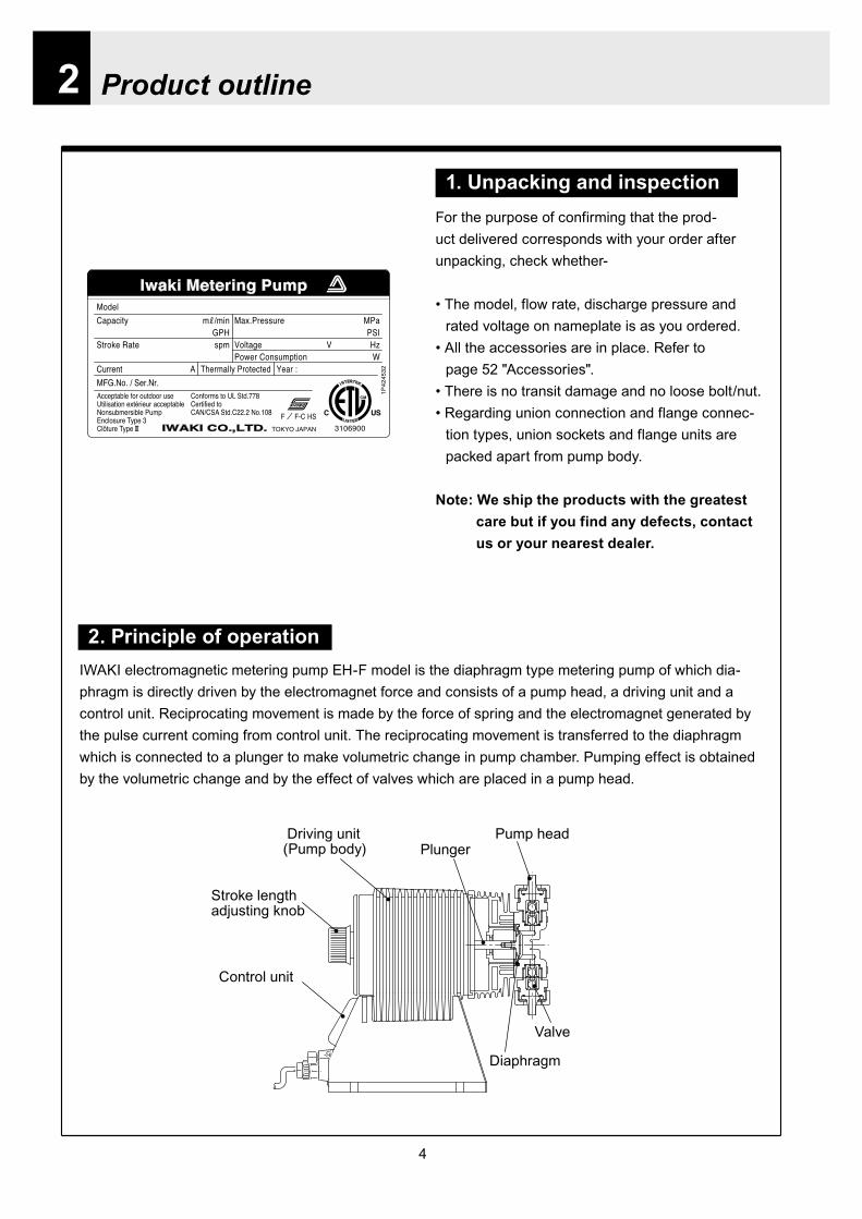
4
2 Product outline
2 Principle of operationIWAKI electromagnetic metering pump EH-F model is the diaphragm type metering pump of which dia-phragm is directly driven by the electromagnet force and consists of a pump head a driving unit and a control unit Reciprocating movement is made by the force of spring and the electromagnet generated by the pulse current coming from control unit The reciprocating movement is transferred to the diaphragm which is connected to a plunger to make volumetric change in pump chamber Pumping effect is obtained by the volumetric change and by the effect of valves which are placed in a pump head
Stroke lengthadjusting knob
Control unit
Driving unit (Pump body) Plunger
Pump head
Valve
Diaphragm
1 Unpacking and inspectionFor the purpose of confirming that the prod-uct delivered corresponds with your order after unpacking check whether-
bull The model flow rate discharge pressure andrated voltage on nameplate is as you ordered
bull All the accessories are in place Refer topage 52 Accessories
bull There is no transit damage and no loose boltnutbull Regarding union connection and flange connec-
tion types union sockets and flange units are packed apart from pump body
Note We ship the products with the greatest care but if you find any defects contact us or your nearest dealer
Handled liquid
5
Product outline
3 Model identification
1 Pump
EH - F 55 VC C6 - 10U -
Series code Driving unit code (Average power consumption) F 100 W Diaphragm effective diameter35 35 mm 45 45 mm 55 55 mm 70 70 mm
Wet end material
PartCode Pump head Valve O ring
Valve seat Gasket Diaphragm
VCPVC
Ceramic FKMPTFE
PTFE+
EPDM(Non wet end)
V6 SUS316 EPDMPC GFRPP Ceramic FKM
Special specification code01 - 99 Non standard material non standard connection or so
Connection hose diameter codeCode Connection hose dia
C6 empty 38 times empty 12C7 empty 58 times empty 34C8 12NPTC12 ANSI 150LB 12
Supply voltage codeCode Supply voltage10U AC115 V (with a plug)20U AC230 V (with a plug)
Allowable voltage range FrequencyAC1035 V - 1265 V 50-60 HzAC207 V - 253 V
Material code PVC Polyvinyl chloride PTFE Poytetrafluro ethylene (Teflon) FKM Fluor rubber (Acid resistant Viton) GFRPP Glass fibber reinforced polypropylene EPDM Ethylene propylene rubberNote Regarding handled liquid acid and alkaline solution is transferred depending on wet end material
Acid solutionAlkaline solutionAcid solution
6
Product outline
2 Controller
EHC - F 10U -
Controller unit type for EH-F EHC Controller EH pump driving unit code
Supply voltage code
Special specification code 01~99 Special specification
Code Average power consumptionF 100W
Code Supply voltage10U AC115V20U AC230V
Allowable voltage range FrequencyAC1035V - 1265V
50-60HzAC207V - 253V
7
Product outline
4 Parts name
1 Pump parts
Pump headLock screw
Driving unit
Control panel
Control unit
Stroke lengthadjusting knob
Socket cord
MAN DIV MULT ANAR V
OVER P12 LOCK Err SET
spm
mA
LED lights orange when Pre-STOP signal comes from level sensor or lights redly when STOP signal comes
Screen indicates operation states and setting values in figures and letters
StartStop key is used tostartstop pump operation
EXT keyis used to start pumpingin EXT operation mode
ON lamp lights as turning on power and blinks synchronously with each stroke
Up key is used to increase the setting values and to change the setting items Pressing Up and Down key at once can have the pump running at full spm
Down key is used to decrease the setting values or to change the setting items Pressing Up and Down key at once can have the pump running at full spm
2 Control unit
8
Product outline
5 Specification
1 Pump specification
2 Control unit specification
Operationmode
MAN (Manual operation) 1 - 240 spm
EXT
DIV (Pulse dividing) 1 - 9999MULT (Pulse multiply) times1 - 9999ANA R (Analog rigid) 4-20 0-20 20-4 20-0 mAANA V (Analog variable) 2 points in a range of 00-200 mA 0 - 240 spmEXT mode consists of the above 4 modes
Display
LCD 14 seg 5 digits spm Operational states and Settings
LEDON Green Lights as turning power on
Blinks synchronous with each strokeSTOP OrangeRed Lights orange when Pre-STOP is activated or lights redly when STOP is activated
Operation 4 keys STARTSTOP EXT UP DOWN
Control function
STOP Pump keeps running when Pre-STOP is activated or stops when STOP is activated
Self priming Pump operates at full speed when both Up and Down keys are depressed together
Key lock Lock and release key padsBuffer memory ONOFF setting is changeable (Initial setting is OFF)
InputPulse No-voltage contact Maximum 100 HzCurrent Range of DC0 - 20 mA (Input resistance 200 Ω)Level sensor Potential free contact or open collector 2-step contact
Output Photo MOS Relay ACDC 24 V 01 Aspm synchronous output The maximum input pulse frequency is 100 Hz however the maximum frequency is variable
depending on the setting of anti-chattering On-time of pulse requires 5 ms or more when ST 05 is selected
5060Hz
ModelsMax discharge
capacitymlmin(GPH)
Max discharge pressureMPa(PSI)
Stroke speed variable range
spm
Stroke length variable range
mm()
Average power
consumption
W
Masskg
EH-F 1 - 240 09 - 225(40 - 100) 100
45 750(119) 07(102)55 1200(190) 045(65)
16
70 2000(317) 03(44)
35 500(79) 10(145)
Note 1 Performance is obtained by pumping clean water at ambient temp at a rated voltage2 Discharge capacity is the value at max discharge pressure (100 stroke length 100
stroke rate) When discharge pressure is low pump discharges liquid much more than the discharge capacity shown above
3 Permissible ambient temperature 0 ~ 40 deg C 4 Permissible liquid temperature VC V6 0 ~ 40 deg C PC 0~60 degC 5 Permissible voltage fluctuation Within plusmn10 of the rated voltage6 Ask us or our distributor for special cases such as transferring slurry liquid
9
Product outline
6 Operational function
1 Manual operation and keys are used to set the number of strokes between 1 and 240 spm The pump startsstops
operation by pushing START STOP key The number of strokes is adjustable in the both pump states of running and stop
ON
ON
OFF
ON ON
STARTSTOP key
Operation
Stop
Operation
Pump operation
External signals
ON
OFF
Pump operation
1 2 3 4 1 2 3 4 1 2 3 4
Set value 14 in dividing operation
2 Pulse dividing operationIn this mode pump runs in the dividing operation for external pulse signals Dividing ratio is variable within the setting range between 9999 1 and 1 1 The upper limit of the number of strokes in the pulse dividing operation is equivalent to the maximum number of strokes in manual operation When the input signals over the upper limit stroke speed is incoming the residual signals can be stored up to 65535
External signals
Pump operationON
OFF
Set value 4 in multiply operation
1 2 3 4 1 2 3 4 1 2 3 4
3 Pulse multiply operationIn this mode pump runs in the multiply operation between 1 and 9999 times for an external pulse signal and stops automatically The number of strokes in the pulse multiply operation is equivalent to the number of strokes in manual operation The incoming pulse signals during the multiply operation motions are cancelled and are stored up to 65535
10
Product outline
4 Analog control operation ANA R(analogue rigid) mode
Pump operates within the range of 0-240 spm in proportion to the external signals between 0-20 mA4 (4-20 20-4 0-20 20-0) patterns are provided and the pump operates within 0-240 spm in proportion to the external signals in each patternIn the 4-20 or 20-4 pattern a breaking detective function becomes active automatically The function stops the pumping operation below 4 mA And an error indication DISCN blinks on the display of con-trol unit When this function is active check wiring This function can be released with STARTSTOP key
42
3
1
Num
ber o
f stro
kes
240
0 4 20
(spm)
Analog input(mA)
Conditions
The left graph is in the following patterns 4 - 20 20 - 4 0 - 20 20 - 0
240220
60
0 6 2017
(spm)
Analog input (mA)
P1
P2
Num
ber o
f stro
kes
Conditions
The left graph is in the following settingP 1 = 6 mA 60 spmP 2 = 17 mA 220 spm
ANA V(analogue variable) modePump operates within the range of 0-240 spm in proportion to the external signals between 0-20 mA Setting 2 points can draw a straight line Depending on the position of the 2 points 0 spm may not come at 0 mA in some cases When the stroke speed could become over 240 spm at some mA due to the set-ting pump speed is limited to 240 spm
11
Product outline
7 Control display instruction
1 Control unit
ON STOP
EXT
EH-F ControllerSTARTSTOP
DIVMAN
OVER P1 2 LOCK Err SETmA
spmMULT ANAR V
Manual operation indication (MAN)shows pump is in manual operation
indicationshows pump is running for self-priming at maximum stroke speed and calls userrsquos attention
mA indicationappears when setting amperage in EXT setting mode for analog control operation
SET indcationappears in user mode and EXT setting mode
Stop indicationappears during Pre-STOP or STOP signal input
Stroke speed indication appears when displayshows stroke speed
Pulse dividing indication (DIV)shows pump is in pulse dividing operation or pulse dividing ratio is being set
Pulse multiply indication(MULT) shows pump is in pulse multiply operation or pulse multiply ratio is being set
Display shows operational state and set values in figures and letters
STARTSTOP keyis used to startstop pump operationThis key is also used to confirm each set value in set modes and used to move to wait mode
EXT keyis used to start pump operation in EXT operation modes
Over indicationlights when incoming signals are surplus to 240 spm in EXT operation
P1 and P2 indicationsappear when 2 points(P1 P2) are set in ANA V(analog variable) mode for analog control operation
Lock indicationappears when keys are locked
ON lampappears as turning on power and blinks synchro-nously with each stroke
Error indicationappears when an error occurs
Analog control operation indication (ANA R ANA V)ANA R indicates pump is in analog rigid operation or setting mode ANA V indicates that pump is in analog variable operation or setting mode
Down key is used to decrease the setting values and to change the setting items Pressing Up and Down key at once can have the pump running at full spm
Up key is used to increase the setting value and to change the setting items Pressing Up and Down key at once can have the pump running at full spm
12
Product outline
2 Typical indications
3 Warning indications
Indications Show
Pump is operating in the manual operation modeThe display shows the set spm
Pump is operating in the analog control mode(ANAV) of the EXT operation Display indicates 168 spm
The stroke speed is being set while pump is operating in the multiply operation(MULT)
Pump is being stopped via STOP input while operating in the dividing operation(DIV)
MAN spm
LOCK SET mA
MAN ANA V spm
MULT
SET
DIV spm
Indications shows
Key lockAll the key operation can be ineffective in order to prevent any per-son other than user from operating the pump This function can be active by pressing STARTSTOP key for 5 seconds in any pump states and LOCK indication appears Key lock function can be released by pressing STARTSTOP key for 5 seconds when LOCK indication appears on the display
The left indication appears when input signal is below 4 mA with the 4-20 or 20-4 pattern in ANA R (Analog rigid) mode In this state pump is under suspensionBy pushing STARTSTOP key once this error is released and the mode moves to waiting mode Check wiring and signals
OVER indication appears when incoming signals are surplus to 240 spm in EXT operation
MAN spm
LOCK SET mA
ANAR
Err
spm
MAN spm
OVER
13
Installation
1 Before installation
Working without disconnecting the power supply may cause an electrical shock Before engaging upon any working procedures involving the pump be sure to turn the power supply switches off to stop the pump and the related devices
Upon becoming aware of a dangerous sign or an abnormal condition while engaging on the installation terminate the work immediately and start it from the beginning again
Do not operate the pump on the voltage which is not specified on the nameplate Failure to do so may result in damage or a fire Be sure to earth the pump
Do not place any dangerous materials or flammable objects near the pump for the sake of safety
WARNING
CAUT ION
1 Dropping the pump or subjecting it to a strong impact may result in the faulty performance Handle the pump with care Do not use the damaged pump for the prevention of the electri-cal leak or shock
2 When installing pump avoid the places where the pump is exposed to the direct sunlight the ambient temperature is above 40 digC or the relative humidity is above 85 Though the pump has a simple waterproof and dust-proof structure it is recommended to protect the pump with a cover when installing it outdoor
3
Installation
14
3 Select a level floor and use the four M6 bolts to firmly anchor the pump so as not to allow any vibration If the pump is inclined the discharge amount may decrease considerably
4 Pump should be installed in a well-ventilated place in summer and free from freezing in win-ter
6 Place the pump as close to the suction tank as possible realizing a flooded suction system (It is recommended the pump should be located lower than the suction-side tank)
7 If the pump is used to feed some liquid that gen-erates air bubbles easily (sodium hypochlorite hydrazine solution etc) the system must be positioned in a cool dark place away from direct sunlight If a tank is installed realize a flooded suction system
5 Select the installation site convenient for the future maintenance and inspection
2 Precaution for piping Piping vibrates due to the pulsation from pump Piping should be supported in order to prevent the vibra-
tion Install an air chamber or an accumulator to reduce the pulsation Ask us for further information Be careful not to have hose bend when arranging tubing It is recommended to arrange the short piping as much as possible The longer piping length the more
pressure drops and can exceed the allowable pressure of pump and can cause the over feed phenom-enon
It is recommended an automatic air bleed valve or a pressure relief valve should be installed in order to release the pressure of discharge piping for maintenance
It is recommended to install a relief valve on the discharge side piping that releases pressure automati-cally
Install a pressure gauge on the discharge side piping in order to measure the pressure inside the piping When installing EH-F pump with the flange connections or the union connections be sure to have the
connections on the discharge side fixation on wall pillar or the frame of equipment for the prevention of vibration Make sure that the piping is fixed as well
CAUTIONIncomplete fixation of pump and piping can lead to the damage to these products Significant vibration often results from the incomplete support for the discharge side connection of pump In case the direct support for the flange or union connection can not be secured try to support pump close to the discharge connection as much as possible
15
Installation
Check valve
Air bleedValve
Discharge hose
Pump
Tree way joint
Accumulator
Drain valve
Discharge valve
Back pressure valve
Pump
Suctionvalve
Air bleed valve
Airchamber
Pressure gauge
Relief valve
3 Piping1 Recommended piping drawings
Arrange piping to meet the suction and dis-charge requirement Especially pay attention to piping arrangement in case of handling the slurry which has settling property
Installation
16
Hose
Hose stopper
Fitting spacer
O ring
Fitting nut
Place hose stoppers with R surfaceface to face with fitting spacer
Hose
Hose stopperFitting spacer
O ring
Fitting nut
Fitting
Suction port
Pump head
2 Piping arrangement1 For hose connection first fit a fitting nut and then a
hose stopper and a fitting spacer in the last place If the hose stopper is not fitted properly leakage may occur and suction amount may decrease
The hose end should be secured by a hose stop-per Insert a hose end into a fitting spacer via a fitting nut and a hose stopper Then squash the hose end between the hose stopper and the fit-ting spacer Finally screw the fitting nut in
The hose stopper should be placed with its R surface face to face with the fitting spacer An incomplete hose stopper fixation or a reverse hose stopper placement can lead to leakage or insufficient suction
CAUTIONReverse hose stopper placement can dam-age hose
Fitting nut is made of plastics The fitting nut may break when it is tightened excessively
If attached hose is not long enough prepare a substitute hose such as chloroethene braided hose and polyethylene hose with a suitable bore to the hose fitting spacer
CAUTIONIt is very dangerous to attach the different size hose It may come off
Insert the fitting spacer into hose as deep as possible If the insertion is not enough hose may come off and leakage may result
Be careful not to lose the attached O rings Leakage or suction failure may result without an O ring
2 Hose connection tends to loose if liquid or ambient atmosphere is higher than normal temperature Re-tighten the fitting nut properly after starting opera-tion Be careful not to tighten the nuts too much
3 When fitting the hose again after detaching it for maintenance cut the end of hose off about 10 mm and insert it
17
Installation
4 Check valveEH-F35 45 (VCV6PC) types are attached with a check valve Fit the check valve to piping in the fol-lowing cases
1 The suction side liquid level is higher than the dis-charge side liquid level (Fig A) When injection point is below the liquid level of suction side at atmospheric pressure
2 The suction side pressure is higher than the discharge side pressure (Fig B)
3 The discharge side liquid level is higher than the suction side liquid level but the differential height between both liquid level is 5 m or below (Fig C)
4 The loading pressure of piping resistance and dis-charge head to the pump is under 013 MPa
Suction side Discharge side
Figure A
Figure B
5m
Figure C
To chemical tankor vessel
Remove check valve
3 Piping for bleedingPrior to bleeding disconnect hose and point a hose end at a suction tank or vessel Remove a check valve if it is attached on the discharge side piping
18
Installation
R12
Oslash12
5 Check valve mounting1 Tap the female thread of NPT12 at an injection
point Check valve is provided with the male thread of R12 Cut off the unused portion to fit it on a pip-ing
2 Apply seal tape on the threaded portion of the check valve and screw it in the injection point Pinch the check valve body lightly with a spanner and tighten it for easy mounting
3 When fitting a hose into a check valve with the check valve on main pipe tighten the fitting nut holding the check valve body by hand
4 Cut the end of check valve(empty 12) accordingly when mounting it in a small pipe It is recommended the end of the check valve comes at the centre of pipe bore
It is recommended to mount a check valve via a valve for maintenance Provide NPT12 female thread and screw it in Valve should be resistant to the chemical liquid in use
Valve
Check valve
Check valve body
Apply seal tape
Fitting nut
Pipe
Cut the end nozzle offif it is too long compared topipe bore
6 Flange connection and union connection1 Flange units and union sockets are packed apart from pump body Fit the flange units or the union sockets to
pump body before use Refer to the following figures2 Secure the sealing by fitting O rings to each connection
CAUTIONWhen mounting flange units or union sockets to pump body be careful not to allow O ring to get out of the groove Especially pay attention to the O ring on the groove on suction side
3 Fix the flange units or the union sockets to the pump body by tightening fitting nuts In this case first tighten the fitting nuts by the hand and then re-tighten it by 90 degrees with a spanner
CAUTION
Fitting nut is made of plastics The fitting nut may break when tightened excessively
Flange connection type
19
Instillation
Flange
Flange
Fitting nut
O ring
O ring
Elbow
Pump body
Fitting nut
Drain
Discharge
Air chamber
7 Accumulator and air chamber mountingInstall an accumulator or an air chamber on piping for the prevention of the vibration from the pulsation of pump discharge hose
20
Installation
8 Piping (General notes)1 Keep piping short and less bends Do not make the projections where air can remains
2 Support piping to avoid having the pump subject to the piping weight especially when wet-end mate-rial is made of PVC
3 In case of transferring the slurry which tends to settle do not make U shape on piping A drain plug is required at the lowest portion of piping as well
4 In case of transferring the viscous or toxic liquid or the liquid which tends to settle provide the piping for cleaning for the purpose of maintenance
5 In case of transferring the high temperature or low temperature liquid the telescopic motion of piping from temperature variation should be taken into consideration
6 Select pipe materials based on a through examination of the corrosive resistance and the estimated pressure applied to piping
7 Do not allow any adhesive agent to get in pump when connecting PVC-made pipe on the discharge side piping
8 Clean the inside of piping before installing pump in it
9 A relief valve is required to protect pump and piping Install a relief valve on the discharge piping near the pump
9 Suction piping1 Regarding suction piping a flooded suction system should be realized The bore of suction piping is
recommended to be larger than that of pump suction port
2 Each joint of suction piping needs to be mounted carefully in order to prevent air from coming in Air influx into piping may cause discharge performance failure and instability
10 Discharge piping1 Mount a relief valve on the discharge piping near pump A discharge valve should be mounted beyond
the relief valve
2 The pressure resistance of discharge piping should be higher than the set pressure of relief valve Mount each joint carefully
21
Installation
4 Electrical wiring
1 Power cord connection
Electrical works and the handling of power source must be done by qualified person
Do not operate pump with the wet hand
Make sure that power is not turned on while working on wirng
Do not dismantle electronic circuit
Electronic circuit may be broken Never apply other voltages than a rated voltage
WARNING
CAUT ION
High power equipment
CAUTION Avoid sharing a power source with a high
power equipment This can lead to the fail-ure of the electronic circuit of control unit due to extremely large surge voltage
The noise from an inverter can cause fail-ure
22
Installation
P
Surge absorption element
PNoise cut transformer
CAUTION
2 Wiring procedure
Electronic circuit of control unit may be failed by extremely large surge voltage Do not use the pump near to the high power equipment of 200V or more which may generate large surge voltage If the use of high power equipment is inevitable take either of the following measuresa Install a surge absorption element such
as varister with 2000A or more durability on the power point
b Install a noise cut transformer
CAUTION
Only qualified operatorsservice staff should be in charge of the related electrical arrange-ment and control of the power source Failure to observe this instruction may result in injury to person or damage to assets
Never connect wires while power is turned on otherwise an electrical shock or a short-circuit of controller may result Be sure to turn off power before wiring
Internal circuit is still electrified right after turning off power Take 1 minute or more to start wiring
Do not band a power cable either electrical wires or relay output wires
Earthing wire is equipped with a jumper pin Keep the jumper pin equipped in use
Do not combine the EXT or STOP signal line with a power cord or a power cable Do not com-bine power source line with the EXT or STOP signal line by a concentric cable (5 wires cable or so) Otherwise noise come about through EXT and STOP wires due to the induction effect from power cable and it may results in wrong operation or the failure of pump
Regarding frequent ON-OFF operation it is recommended to stop pump thorough STOP input terminal but not by connecting or disconnecting power source When connecting and discon-necting power cord can not be avoided it should be within 6 times an hour
23
Installation
Procedure to connect the signal cordUse DIN connector of five poles and four polesThe following connectors made by Binder in Germany are recommendedAsk IWAKI for the detail of Binder connector 5 poles 713 series 99-0436-10-05 for input signal 4 poles 715 series 99-0430-15-04 for level sensor
The following connector made by Hirschmann in Germany is recommendedAsk IWAKI for the detail of Hirschmann connector 4 poles GDS307 for output
The following procedures are based on the connector made by Binder and HirschmannIf a similar connector is used the wiring should be made according to the instruction manual of the manufacturer of connector
In case of Binder connector(1) Dismantle the connector and pass the wire through it Outer diameter of the cable should be oslash4-6
Using the different cable in diameter the connector can not be sealed properly
(2) Strip the cable ends and insert wire to the appropriate positions and connect them with screwsThe maximum allowable cross section of the wire is 075mm2
(3) After connecting the wire assemble the connector securely Slightly pull the cord to confirm that the cord connection is secured Perfect sealing can not be obtained unless the cord connection is loose
24
Installation
In case of Hirschmann connector(1) Dismantle the connector and pass the wire through it Insert a minus screw driver into the place shown by
ldquoLIFTrdquo and lift it up Outer diameter of the cable should be 35-6 mm Using the different cable in diam-eter the connector can not be sealed properly
(2) Strip the cable ends and insert wire to the appropriate positions and tighten them with screwsThe maximum allowable cross section of the wire is 075mm2
(3) After connecting wire assemble the connector securely Slightly pull the cord to confirm that the cord connection is secured Perfect sealing can not be obtained unless the cord connection is loose
Terminal position
NA Not Applicable
Connection of level sensorThe controller corresponds to two stage level sensor Connect the pre-alarm signal to Pre-STOP and the alarm signal to STOP When the pre-alarm signal comes in the orange lamp lights but the pump does not stop When a contact type is used connect wires to STOP and COM2 For open collector output level sensor Pay attention to the polarity Pre-Stop and STOP are plus (+) and COM2 is minus (-) (Max charged voltage 5V Current 18mA) For contact output level sensor Use the one designed for electronic circuit and the minimum applicable load of 1mA or less
Connection inside connector 1 STOP 2 Pre-STOP 3 Free 4 COM2
1
2
3
4 CLOSE
ON
PUMP
Level Sensor(STOP)
OPEN
Pulse
COM
+12VDC
NA
ANA(4-20)
Pre-STOP
STOP
COM
NA
OUT
25
Installation
Stop functionStop function is the function to stop the pump by the external signal Connect the wires to STOP and COM2 in the same way as the level sensor connection
CAUTION
Frequent stop and start of pump should be done by using STOP function (ON and OFF of STOP terminal) If you can not use STOP function and are forced to operate pump by turning OFF and ON of power source ON and OFF of power source should be limited to six times an hour
Pulse signal inputPulse signal input is used when the pump runs in the DIV or MULT of EXT modeDIV means dividing and MULT means multiply In case of open collector signal Pay attention to the polarity Pulse is plus (+) and COM1 is minus (-) (Max charged voltage 5V Current 18mA) In case of contact signal Use the one designed for electronic circuit and the minimum applicable load of 1mA or less
Connection inside connector 1 Free 2 Pulse 3 Free 4 12VDC 5 COM
3
2
4
15
Analog signal inputAnalog signal input is used when the pump runs in ANAR or ANAV of EXT modeANAR means analog rigid and ANAV means analog variable
Connection inside connector 1 ANA 2 Free 3 Free 4 Free 5 COM
3
2
4
15
26
Installation
Output signalOUT Photo MOS relay outputStandard is output synchronous with stroke Output is activated synchronous with each pump stroke
Connection inside connector 1 OUT 4 OUT
OUT 1
2
34
Surge voltage The electronic circuit of the control unit may be affected by excessively high surge voltage Do not operate the pump near the high-power elec-trical equipment of 200V or above that generates high surge voltage Under unavoidable circumstances take either of the following measures(1) Use a surge absorbing element (such as a
varistor with the surge resistance of 2000A or more) at the pump power supply connection
(2) Use a noise-cut transformer
Surge absorbing element
Noise-cut transformer
1 Preparation for pump operationBefore pump operation check that
bull Liquid tank is filled enough Supply liquid if it is less than the required levelbull There is no liquid leakage or congestion due to breakagebull Both suction and discharge side valves are openedbull Pump is connected to the predetermined power source correctlybull Electrical wiring is correct and there is no possibility of a short circuit or current leakage
2 BleedingBleeding is a process to eliminate the air inside the suction-side piping Be sure to carry out an air elimi-nation prior to initiating the pump operation after replacing the liquid inside a tank and after a long peri-od of storage Air gushes together with chemical liquid when carrying our bleeding For safety reasons first turn the end of a bleeding hose to a tank or a container
CAUTION
Some liquids may cause skin trouble or affect the quality of mechanical parts Wipe off chemi-cal liquid immediately when they splash on the hand or mechanical parts
27
Operation
1 Pump Operation
WA R N I N G Wear protective clothing
Wear protective clothing such as a protective mask safety gloves or so when handling chemical liquid
Do not operate pump with a discharge-side valve completely closed Operating the pump with the discharge-side valves fully closed may cause the liquid spillage or
the extremely high pressure inside the pump or the discharge-side pipingtubing This could lead to a piping burst Be sure not to operate pump with the discharge-sides valve closed
CAU T I O N A long time dry running (longer than 30 minutes) may cause the pump overheat and it could lead
to the deformation of the pump unit consists of a pump head and valve cases or so or may loosen the pump head fitting and result in liquid leakage
If the hex socket cap bolts on a pump head are loosened liquid leakage may resultBe sure to fasten all the 6 or 8 hex socket cap bolts tightly before starting the initial pump opera-tion And periodically check the looseness of the bolts on the pump head and retight the bolts as necessary
bull Tightening torque255NbullmTighten all the bolts diagonally applying equal tightness
If electric wiring gets wet due to accidental liquid spillage fire or electrical shock may occur Never get it wet When the electric wiring gets wet turn off power and wipe the liquid away
A frequent ON-OFF operation should be conducted by using STOP function(ON - OFF signals to STOP terminal) In case the STOP function is not available for the ON-OFF operation the ON - OFF operation by turning onoff power should be limited to six times an hour
4
28
3 Procedure for bleeding
Check valve should be removed
To tank or drain pan
100
75
50
25
0 25 50 75 100
(Fixed stroke length)
Stroke length adjustment
240spm
180spm
120spm
Flow
rate
Operation
[1] Extend the tube connected to the discharge-side fitting nut of pump to a chemical tank or a drain pan Then start pump operationbull Remove a check valve if it is installed on dis-
charge-side
[2] Operate the pump for about 10 minutes to eliminate air completely
[3] When the air in pump head is completely eliminated and liquid is replaced return the discharge-side tube to the regular tubing position
[4] Finally make sure there is no leakage in any section
4 Discharge capacity adjustmentDischarge capacity can be adjusted by both the stroke length adjustment and the stroke rate adjust-ment but basically adjust it via the stroke rate adjustment Stroke length adjustment is an auxiliary way to cover the range where the stroke rate adjustment can not reachPay attention to the following for correct procedure
Stroke rate adjustment(1) For some liquids which diffuses gas such as sodium hypochlorite and hydrazine solution adjust discharge capac-
ity by means of the stroke rate adjustment with the stroke length about 100 Gas lock may occur if the stroke length is set to short
(2) When the back pressure on discharge side is high adjust discharge capacity by the stroke rate adjustment with the stroke length about 100
(3) In case reaction is greatly influenced depending on the discharge capacity per pump shot in the application of neutralization or titration adjust discharge capacity by the stroke rate adjustment with the shortened stroke length and reduce the discharge capacity per shot
1 Discharge capacity adjustment procedureAppropriate stroke length and stroke rate are decided on the pump operating condition and liquid characteristics Following ways are recommended for proper calibration
(1) Set stroke length at 100 and roughly adjust discharge capacity by adjusting stroke rate
(2) Measure discharge capacity(3) If the measured capacity is below the wanted value
increase the stroke rate and measure again the dis-charge capacity
(4) Adjust stroke length for the fine adjustment of discharge capacity(5) Determine a discharge capacity at the last and confirm the wanted capacity is discharged
CAUTION
29
100
75
50
25
0 60 120 180 240spm
Fixed stroke length
Stroke rate adjustment
Flow
rate
Screw driverOPEN
LOCK
100
75
50
25
0 25 50 75 100
Fixed stroke rate
Flow
rate
Stroke length adjustment
Operation
2 Stroke rate adjustmentStroke rate is adjusted by the key operations of control unit Control the plunger stroke rate per minute from 1 to 240 spm via control unit
3 Stroke length adjustmentStroke length adjustment knob is locked with a screw Loosen the screw before adjustment and lock it afterwards
(1) Turn on pump and adjust the discharge capacity by turning the stroke length adjusting knob while pump is running
(2) The left graph shows the relation between stroke length and discharge capacity The maximum dis-charge capacity is shown on the name plate
bull The usage between 40 and 100 is practi-cal
Do not turn the stroke length adjusting knob when pump stops
CAUTIONBe sure to tighten the screw on the adjust-ment knob after an adjustment The knob may rotate unintentionally due to a loose fixation This may result in the fluctuation in a discharge rate
30
Mode ParameterDefault value
Setting range Step
Manual operation Stroke speed 240 1-240DIV setting Dividing ratio frasl 1 1-9999
MULT setting Multiply ratio times1 times1-9999ANA R setting 4-20 4-20 20-4 0-20 20-0
ANA V setting
P1 amperage 40 00-200P1 stroke speed 0 0-240P2 amperage 200 00-200P2 stroke speed 240 0-240
User setting
EXT operation ANA V DIV MULT ANA R ANA V
Anti-chatteringMECH MECH ELECST05 ST05 ST20 ST50FT01 FT02 FT04
Buffer memory MEM-N MEM-N MEM-Y
111-
011
011
2 Control unit operationEH-F type pump is controlled by means of setting or changing the setting values of the controller Control functions are various at each operation mode Read this section carefully before operation
Default parameter values
5 Full operationPut pump in use after bleeding and adjusting discharge capacityPump runs in manual operation or in accordance with the setting of control unit
6 Manual operationStarting pump After turning on power ON lamp (Green) appears and display shows WAIT mode For
the first time to turn on power MAN lamp appears and pump starts after pushing STARTSTOP key once
Stop pump Push STARTSTOP key to turn off MAN lamp and stop pump Pump starts and stops every time STARTSTOP key is pressed
7 EXT operationRefer to the next section of 2 Control unit operation
8 Shout down When pump will not in use for a long time (one month or more)
Run pump with clean water about 30 minutes in order to clean the wet-end parts and the inside of pip-ing before storage
When re-starting pump after a long time storage If pump dose not suck up liquid clean valve sets and remove the sticking foreign matters Carry out an air elimination and adjust discharge capacity when air stays inside pump head Refer to page 28 3 Procedure for bleeding
Operation
---
-
31
AN
A V
(Ana
log
var
iabl
e)
DIV
(Pul
se d
ivid
ing)
MU
LT(P
ulse
mul
tiply
)A
NA
R(A
nalo
g ri
gid)
SE
TS
ET
Use
r mod
e
EX
T m
ode
sele
ctio
n
EX
T
EX
TE
XT
EX
TE
XT
EX
T EX
T
EX
T
EX
T
EX
T
EX
T
EX
T
EX
T
EX
T
EX
T
EX
T
EX
T
EX
T
3 sec
onds
or m
ore
Wai
t mod
e
Set
ting
of fi
xatio
n pa
ttern
EX
T m
ode
Man
ual o
pera
tion
Set
ting
of s
troke
num
ber
AN
A R
(Ana
log
rigi
d)M
ULT
(Pul
se m
ultip
ly)
DIV
(Pul
se
div
idin
g)
AN
A V
(Ana
log
var
iabl
e)
anti-
chat
terin
gse
tting
dis
play
Setti
ng o
f div
idin
g ra
tioS
ettin
g of
cou
nt n
umbe
r
Curre
nt va
lue of
P1
Stro
ke nu
mbe
r of P
1
Curre
nt va
lue
of P
2
Stro
ke nu
mbe
r of P
2
EX
T O
pera
tion
Dis
play
EX
T se
tting
mod
e
Buf
fer m
emor
yse
tting
dis
play
Pow
er O
N
spm
MA
Nsp
m
spm
DIV
DIV
SE
TS
ET
MU
LT
MU
LTsp
mA
NA
V
spm
AN
AR
AN
AR
SE
Tm
AS
ET
mA
spm
AN
A
V
P1
mA
SE
T
spm
AN
A
V
P1
AN
AR
SE
Tm
A
AN
AR
SE
Tm
AS
ET
AN
A
V
P 2
SE
T
spm
AN
A
V
P 2
AN
AR
SE
Tm
A
AN
A
V
SE
TS
ET
SE
T
SE
T
SE
T
SE
T
SE
T
SE
T
SE
T
SE
T
SE
TS
ET
1 Overview Operating Scheme
Operation
1 means automatic transfer WAIT mode is selected when the power is switched on for the first time On and after the initial power activation pump restores the previous status right before the power is switched off
2 Regarding MANUAL mode pump starts operation by pushing STARTSTOP key at WAIT modePushing STARTSTOP key again the pump stops and returns to WAIT mode
3 Regarding EXT operation pushing EXT key at WAIT mode the pump moves to EXT mode and starts operationPushing STARTSTOP key stops the operation and returns the pump to WAIT mode
4 The change of each setting of EXT operation is accessible by pushing EXT key at EXT mode Pushing EXT key after the setting pump starts in EXT operation according to the changed setting
5 Pushing EXT key for 3 seconds at WAIT mode pump moves to USER mode At USER mode the EXT mode selection and the detailed setting such as the setting of buffer memory or so can be obtained
For details refer to each section of 2 Pump operation
2 Pump operation1 Operation of controller
Before turning on power confirm the specified power source on the nameplate
CAUTION
Connecting any other powers than the one shown on nameplate to pump is strictly prohibitedIt could lead to pump trouble or failure
Operation
32
1 Turning on powerDisplay shows WAIT mode when pump is turned on for the first time After the initial power activation the pump restores the previous mode right before the power was turned off last time If power is turned off at any setting modes WAIT mode appears at the next power activation
Stroke speed setting value is shown on display at WAIT mode ON lamp lights (Green)
EXT
EH-F ControllerSTARTSTOP
ON STOP
spm
33
2 Manual operation(1) Stroke speed can be adjusted by and
keys The figure changes quickly when either or key is depressed The picture below
shows the stroke speed is set to 160 spm
EXT
EH-F ControllerSTARTSTOP
ON STOP
spm
EXT
EH-F ControllerSTARTSTOP
ON STOP
MAN spm
EXT
EH-F ControllerSTARTSTOP
ON STOP
spm
(2) Push STARTSTOP key once to start the pump operation MAN indication appears and ON lamp blinks synchronously with each stroke
(3) MAN indication disappears and ON lamp stops blinking as STARTSTOP key is pushed again Pump enters WAIT mode
Operation
Operation
34
EXT
EH-F ControllerSTARTSTOP
ON STOP
ANA V
P1 SET mA
EXT
EH-F ControllerSTARTSTOP
ON STOP
P1 SET
ANA V spm
EXT
EH-F ControllerSTARTSTOP
ON STOP
spm
EXT
EH-F ControllerSTARTSTOP
ON STOP
ANA V spm
(4) Set the current value at P1 Figure increases or decreases as or key is pushed The pic-ture below shows 80 mA is set to point 1
EXT
EH-F ControllerSTARTSTOP
ON STOP
ANA V
P1 SET mA
(5) Pushing EXT key once spm appears on the display while mA disappears The picture below shows the number of strokes at P1
EXT
EH-F ControllerSTARTSTOP
ON STOP
P1 SET
ANA V spm
3 EXT operation (ANA V mode)(1) Push STARTSTOP key to move to WAIT mode
if pump is in another mode Go to next step if pump is in WAIT mode
(2) ANAV indication appears and pump enters an EXT mode as EXT key is pushed once Pump starts operation in accordance with current sig-nals and various settings ON lamp blinks at each pumping during operation Pump is con-trolled via the EXT mode which was select-ed at USER mode The initial setting of EXT mode is ANA V mode Select a preferable EXT mode in USER mode The picture below shows ANA V mode (The spm on the display changes according to input signals)
(3) Push EXT key once when pump is running in ANA V mode Display indicates the setting display of ANA V mode spm indication dis-appears and P1 SET and mA indications appear on the screen
(6) Set the number of strokes at P1 Figure increasesdecreases as key is pushed Picture below shows 10 spm is set for point 1
Operation
35
(7) Push EXT key to move to the setting display of the current value at P2 P1 and spm disap-pear and P2 and mA appears instead
EXT
EH-F ControllerSTARTSTOP
ON STOP
ANA V
P 2 SET mA
EXT
EH-F ControllerSTARTSTOP
ON STOP
ANA V
P 2 SET mA
EXT
EH-F ControllerSTARTSTOP
ON STOP
P 2 SET
ANA V spm
(11) Push EXT key to return to EXT mode Pump starts to run in ANA V mode on the setting of (4) through (10) ON lamp starts to blink at each pumping
EXT
EH-F ControllerSTARTSTOP
STOPON
ANA V spm
EXT
EH-F ControllerSTARTSTOP
ON STOP
P 2 SET
ANA V spm
EXT
EH-F ControllerSTARTSTOP
ON STOP
spm
(8) Set the current value of P2 by pushing and keys Picture below shows 180 mA is set to
point2
(9) Pushing EXT key once spm appears on the display while mA disappears The picture below shows the number of strokes at P2
(10) Set the number of strokes at P2 by pushing and keys Picture below shows 200
spm is set to point 2
(12) Pushing STARTSTOP key pump enters WAIT mode and pump stops ON lamp stops blink-ing and ANAV indication disappears
CAUTIONWhen the setting of the buffer memory is OFF keep the number of strokes in the dividing operation 240 spm or below The input signals to operate the pump over 240 spm can cause an unstable pump operationWhen the setting of the buffer memory is ON the pump operates for all the input pulse signalsPump keeps operating after all the signals are stopped in this case Be careful when setting of buffer memory
Operation
36
EXT
EH-F ControllerSTARTSTOP
ON STOP
DIV
SET
EXT
EH-F ControllerSTARTSTOP
ON STOP
DIV
SET
EXT
EH-F ControllerSTARTSTOP
STOPON
DIV spm
EXT
EH-F ControllerSTARTSTOP
ON STOP
spm
(2) Pushing EXT key DIV appears and pump starts operation in the ratio of input pulse sig-nals a pumping ON lamp blinks synchronous-ly at each pumping The initial setting of EXT selection is ANA V mode Change mode to DIV mode via USER mode Refer to P 40 for detail information
(3) Push EXT key while pump is operating in DIV mode Pump stop running and SET indication appears on the DIV setting display in stead of spm indication
(4) Enter a dividing ratioFigure increasesdecreases when key is pushed The picture below shows 10 is set
4 EXT operation (DIV mode)
(1) Push STARTSTOP key to move to WAIT mode if pump is in another mode Go to next step if pump is in WAIT mode
CAUTIONOn condition the setting of buffer memory is OFF do not input any pulse signals during the pumping motions for a input pulse signal in the multiply operation These input pulse signals are cancelledWhen the setting of buffer memory is ON pump operates for all the input pulse signals
Operation
37
EXT
EH-F ControllerSTARTSTOP
ON STOP
spm
EXT
EH-F ControllerSTARTSTOP
STOPON
DIV spm
EXT
EH-F ControllerSTARTSTOP
ON STOP
spm
EXT
EH-F ControllerSTARTSTOP
ON STOP
MULT
(5) Push EXT key to return to EXT operating mode Pump starts to run on the setting at item (4) ON lamp blinks synchronously at each pumping
(6) Pushing STARTSTOP key pump enters WAIT mode and pump stopsDIV indication disappears and ON lamp stops blinking
5 EXT operation (MULT mode)
(2) MULT indication appears and pump starts running in an EXT operation mode in the ratio of an input pulse signal pumpings as press-ing EXT key ON lamp blinks at each pump-ing Display shows the rest of the number of strokes In MULT mode the number of strokes is equal to the setting value in manual opera-tionThe initial setting of the EXT mode selection is ANA V mode which is the operation in pro-portion to current First select MULT mode via USER mode Refer to P 40 for detail informa-tion
(1) Push STARTSTOP key to move to WAIT mode if pump is in another mode Go to next step if pump is in WAIT mode
Operation
38
EXT
EH-F ControllerSTARTSTOP
ON STOP
spmEXT
EH-F ControllerSTARTSTOP
ON STOP
ANAR spm
EXT
EH-F ControllerSTARTSTOP
ON STOP
MULT
SET
EXT
EH-F ControllerSTARTSTOP
ON STOP
MULT
EXT
EH-F ControllerSTARTSTOP
ON STOP
spm
EXT
EH-F ControllerSTARTSTOP
ON STOP
MULT
SET
(5) Push EXT key to return to MULT mode(3) Pushing EXT key when pump is running in the multiply operation calls the setting display of MULT mode and SET indication appearsPump stops running and ON lamp stop blinking
(4) Enter the number of pumpings per input signalFigure increasesdecreases when key is pushed The picture below shows the pump-ing number is set to 1800 times per an input signal
6 EXT operation (ANA R mode)(1) Push STARTSTOP key to move to WAIT mode
if it is in another mode Go to next step if it is in WAIT mode
(6) Pushing STARTSTOP key recalls WAIT mode and pump stops spm indication appears in stead of MULT indication
(2) Pushing EXT key ANAR appears and pump starts running in the ratio of an input pulse sig-nal pumpings ON lamp blinks at each pump-ing The initial setting of the EXT mode selec-tion is ANA V mode which is the operation in proportion to current is selected First select ANA R mode in USER mode Refer to P 40 for more information
Operation
39
EXT
EH-F ControllerSTARTSTOP
ON STOP
ANAR
SET mA
EXT
EH-F ControllerSTARTSTOP
ON STOP
ANAR spm
EXT
EH-F ControllerSTARTSTOP
ON STOP
ANAR
SET mA
EXT
EH-F ControllerSTARTSTOP
ON STOP
spm
(4) Figure increasesdecreases when key is pushed The picture below is when it is set to 0-240 spm for 20-4 mA
(5) Push EXT key to return to EXT mode Pump starts to run on the setting at item (4) ON lamp blinks synchronously at each pumping
(6) When pushing STARTSTOP key pump enters WAIT mode and stops running ON lamp stops blinking and ANAR disappears
(3) Pushing EXT key when pump is running in the multiply operation calls the setting display of ANAR mode and SET and mA indications appear while spm disappears Pump stops running and ON lamp stops blinking
Operation
40
EXT
EH-F ControllerSTARTSTOP
ON STOP
ANA V
(5) Push EXT key to confirm the desired EXT mode Pump displays the EXT mode selection The picture below shows DIV appears to indi-cate DIV mode is selected
EXT
EH-F ControllerSTARTSTOP
ON STOP
DIV
EXT
EH-F ControllerSTARTSTOP
ON STOP
SET
EXT
EH-F ControllerSTARTSTOP
ON STOP
spm
EXT
EH-F ControllerSTARTSTOP
ON STOP
spm
EXT
EH-F ControllerSTARTSTOP
ON STOP
SET
7 USER settingThe setting of each function is changed in USER mode Have the pump entering WAIT mode in order to move to USER mode OUT (Output) is synchronous with spm and it can not be changed
7-1 EXT mode selection Any one of DIV (pulse dividing) MULT (pulse multiply) ANAR (analog rigid) or ANAV (analog vari-able) can be active in EXT mode The initial mode when shipped from factory is ANAV
(1) Push STARTSTOP key to move to WAIT mode if it is in another mode If it is in WAIT mode go to next step
(2) Press EXT key for more than 3 seconds to move to USER mode The picture below shows pump enters the EXT mode selection
(3) Pushing EXT key SET appears and display shows the mode currently set Picture below shows ANA V mode is selected
(4) Push or key to select a desired EXT mode The picture below shows DIV mode is selected
(6) Push STARTSTOP key to move to WAIT mode spm appears while DIV goes out
Operation
41
EXT
EH-F ControllerSTARTSTOP
ON STOP
spm
EXT
EH-F ControllerSTARTSTOP
ON STOP
ANA V
EXT
EH-F ControllerSTARTSTOP
ON STOP
SET
(3) Push key once
EXT
EH-F ControllerSTARTSTOP
ON STOP
(4) Push key again to move to the anti-chatter-ing setting display
EXT
EH-F ControllerSTARTSTOP
ON STOP
(5) Pushing EXT key display shows the mode cur-rently set and SET appears on it The picture below shows when MECH is selected
EXT
EH-F ControllerSTARTSTOP
ON STOP
SET
7-2 Setting of anti-chattering Anti-chattering function is settable against the incoming pulses during the DIV or MULT operation For the long chattering of mechanical contact such as relay set a large figure via MECH For the high speed (high frequency) chattering of the semi-conductor type contact such as transistor set a small figure via ELEC ST05 of MECH is initial setting
(6) Select MECH by or key for a mechani-cal contact And select ELEC for a semi-conductor contact The picture below shows ELEC is selected
(1) Push STARTSTOP key to move to WAIT mode if it is in another mode If it is in WAIT mode go to next step
(2) Press EXT key for more than 3 seconds to move to USER mode The picture below shows pump enters the EXT mode selection
Operation
42
EXT
EH-F ControllerSTARTSTOP
ON STOP
SET
(7) Push EXT key to display the current set state The picture below shows FT01 is selected
EXT
EH-F ControllerSTARTSTOP
ON STOP
SET EXT
EH-F ControllerSTARTSTOP
ON STOP
EXT
EH-F ControllerSTARTSTOP
ON STOP
spm
7-3 Setting of buffer memoryIn case pump operation can not catch up with the input pulse signals in DIV or MULT operation exces-sive pulse signals can be put in memory up to 65535 pulses However the excessive pulses can not be restored if once power is off or mode is changed
EXT
EH-F ControllerSTARTSTOP
ON STOP
spm
(2) Press EXT key for 3 seconds or more to move to USER mode The picture below shows the EXT mode selection display
EXT
EH-F ControllerSTARTSTOP
ON STOP
ANA V
(8) Set a large figure for the long chattering by or key and set a small figure for high speed (high frequency) chattering The picture below shows FT04 is selected
(9) Push EXT key to return to the anti-chattering setting display SET indication disappears
(10) Push STARTSTOP key to return to wait mode spm indication appears
(1) Push STARTSTOP key to move to WAIT mode if it is in another mode If it is in WAIT mode go to next
Operation
43
(3) Push key once
EXT
EH-F ControllerSTARTSTOP
ON STOP
(7) Push or key in order to set buffer memo-ry to ON or OFF Select MEM-Y to set it ON Select MEM-N for OFF setting The picture below shows when ON is set
EXT
EH-F ControllerSTARTSTOP
ON STOP
SET
(4) Push key once again
EXT
EH-F ControllerSTARTSTOP
ON STOP
(8) Push EXT key to return to the buffer memory setting display SET indication disappears
EXT
EH-F ControllerSTARTSTOP
ON STOP
(9) Push STARTSTOP key to return to WAIT mode spm indication appears
EXT
EH-F ControllerSTARTSTOP
ON STOP
spm
(5) Push key once again and the buffer memory setting display is shown
EXT
EH-F ControllerSTARTSTOP
ON STOP
(6) Push EXT key in order to display the current set state SET indication appears The picture below shows the buffer memory is set to OFF
EXT
EH-F ControllerSTARTSTOP
ON STOP
SET
Operation
44
8 Bleeding amp self-primingAt WAIT mode Manual operating mode and EXT operating mode pump operates at max speed tak-ing priority over any functions when both and keys are pushed at once Pump runs at max speed only when both keys are depressed Pump state returns to the previous mode once either or key is released Pressing and keys for 10 seconds keeps pump running at maximum speed In this state this fixation is released when pushing either or key once and pump returns to the previous mode
(1) When pump is running in ANAV mode
EXT
EH-F ControllerSTARTSTOP
ON STOP
ANA V spm
(2) Pump start to run at full speed when and keys are pressed at once Display shows
PRIME If either or key is released pump returns to the previous mode In this case pump returns to ANAV mode
EXT
EH-F ControllerSTARTSTOP
ON STOP
ANA V
(3) Pressing both and keys simultaneously for 10 seconds or more pump continues to run at full speed even if both keys are released In this case indication appearsPush either or key to release this state indication disappears and pump returns to the previous mode In this case pump returns to ANAV mode
EXT
EH-F ControllerSTARTSTOP
ON STOP
ANA V
Operation
45
10 Error display and release(1) In case Input signals fall to 4 mA or below while
4-20 or 20-4 is set to ANA R mode pump stops with DISCN blinking and Err on dis-play
(2) This error state can be released by push-ing STARTSTOP key and pumps enters wait mode In this case check the wiring and input signals
EXT
EH-F ControllerSTARTSTOP
ON STOP
ANAR
Err
spm
EXT
EH-F ControllerSTARTSTOP
ON STOP
spm
9 Key lockKey lock function is to prevent pump from being operated by some other person than user If STARTSTOP key is pressed for five seconds or more when pump is running or stops all key operations become ineffective with LOCK indication on display This function can be released by pressing STARTSTOP key for 5 seconds while LOCK lights
EXT
EH-F ControllerSTARTSTOP
ON STOP
MAN spm
LOCK
46
Do not conduct a maintenance work with the wet hands It can cause an electric shock
Before dismantling pump be sure to turn off power and check the pump is not electrified Do not
start a dismantlement work after stopping the pump by pushing the STARTSTOP key only Put up
the sign of ldquoMaintenance work is in progressrdquo in order to prevent a pump switch from turning on
unintentionally during the work Release the pressure of discharge piping and drain the liquid from
the wet end parts And then clean the inside of pump head
Wear protective clothing such as a protective mask globes goggles and chemical-proof wear
according to the handled chemical liquid during the work
WARNING
5 Maintenance
1 Trouble shootingTrouble Cause Troubleshooting
Pump dose not start Faulty wiring or disconnection in wiring Voltage is too low Failure in the electronic circuit of control unit
Pump dose not suck liquidDischarge amount is low
Air suction from suction piping Valve gasket is not installed Valve set assembling direction is wrong Pump is air-locked Pump stroke length is too short Suction-sidedischarge-side valve is clogged with
foreign matter Adhesion of valve onto valve seat
Discharge amount fluctuates
Liquid leaks
Key operation is ineffective Key is locked Release key lock
Pump doesnt run
Pump is in waiting mode Signals are not coming for EXT operation Pump is in EXT setting mode Pump is suspended with STOP
Move to operation mode Check wiring and correct the wrong part Move to EXT operating mode Release STOP function
Abnormal noise
Suction-sidedischarge-side valve is clogged with foreign matters
The sound absorption gasket is worn out Bearing is worn out Spring is damaged
Piping vibrates due to pulsation Bearing is worn out Spring is damaged
Install a accumulator or an air chamber The end of pump life span The end of pump life span
Suction-sidedischarge-side valve is clogged with foreign matters
Air is trapped in pump Overfeeding Diaphragm is damaged
Fittings are not tightly closed Pump head is not tightened Diaphragm is damaged O ring and valve gasket are not installed O ring is damaged
Correct wiring Inspect power source and provide measurement Replace the whole unit
Arrange piping again Install valve gasket Reassemble valve set Carry out air elimination Drive pump with 100 stroke length to prime liquid Then
reset stroke length Disassemble inspect and clean Disassemble inspect and clean
Tighten fittings Tighten pump head Replace diaphragm Install O ring and valve gasket Replace O ring
Disassemble inspect and clean
Carry out air elimination Install a check valve or a back pressure valve Replace diaphragm
Disassemble inspect and clean
The end of pump life span The end of pump life span The end of pump life span
Abnormal vibration
Input pulse can not be read Signals are not coming Anti-chattering setting is not proper
Check wiring and correct the wrong part Change the setting properly
Analog signal input can not be read
Wrong wiring Signals are over acceptable loaded resistance
Check wiring and correct wrong part The load resistance is 200Ω Use some devise which can
accept the load resistance
47
CAUTION Check periodically whether the bolts fixing pump head are tightened Tighten them as needed
The bolts fixing pump head may loosen in operation Tightening torque 255Nbullm
Maintenance
3
bull Tighten joint where leakage has occurredbull The excessive air bubbles in the discharged liquid mean air suc-
tion has been caused in system Examine the piping and tighten joint on where leaks
Is there liquid leakage or air suction at any joints on pump or piping
2 Maintenance and inspection
1 Daily inspectionPay attention to the following points during pump operation Stop pump immediately upon detecting abnormality and take measures according to the item Troubleshooting When wear parts come to the life time replace them by new ones
No
1
2
Check Point Description
Does pump lift liquid normally
bull Is liquid normally fedbull Is suction pressuredischarge pressure at normal levelbull Has liquid undergone quality change crystallization or solidifica-
tion
Abnormal noise or vibrationbull Abnormal noise or vibration may happen from the abnormal func-
tioning of pump
EXT setting can not be stored
After EXT setting STARTSTOP key is pushed for EXT by mistake
Push EXT key to operate pump in EXT mode
ldquoPRIME is kept indicated and other operations are inac-cessible
Self-priming function is active Push either or key to release the function
Analog signal input can not be read and DISCN indication appears
Wrong wiring or disconnection Check wiring and correct the wrong part Refer to page 45
for how to release an error indication
Trouble Cause Troubleshooting
48
Maintenance
2 Wear partsWear parts should be replaced in proper period for a long period of pump operation It is recommended that follow-ing parts are always ready for the replacementVC V6 PC P6 types
Parts Qty Life span
Pum
p he
ad
Valve set
EH-F35 EH-F45 EH-F55middot70
2sets
8000hours
Diaphragm 1
Refer to exploded view
Bac
k pr
essu
re v
alve
1
2
Che
ck v
alve
7 6 1
8 11 1
Diaphragm seat 1
O ring
Poppet check valve (With check gasket)
Check valve spring Spacer
Diaphragm
O ring
Note Durability of wear parts depend on the pumped liquid temperature and pressure Time to be replaced mentioned as above is the estimation obtained by continuous pump-ing of clean water at ambient temperature
8000hours
4000hours
49
3 Dismantlement and assembly
Getting wet with or coming in contact with chemicals and toxic liquid is harmful Wear protective clothing such as a protective mask globes goggles and chemical-proof wear during the work
Risk of electrical shock Be sure to turn off power and confirm that pump and devices are not electrified before the work
Release the pressure inside pump and a discharge hose by opening an air bleed valve on piping prior to loosening the piping connections or the dismantlement of pump Dismantlement with the pressure inside pump could lead to liquid spillage
Be careful not to touch residual liquid when dismantling pump Some liquids are harmful for skin or component parts Wipe off liquid when the hand or the component parts come in contact with liquid
WARNING
CAUT ION
Hose
Hose stopperFitting spacer
O ring
Fitting nut
Fitting
Pumphead
Remove the fittingwith a spanner
1 Valve set replacement Dismantlement1 Loosen a fitting nut and remove the hose con-
nected to pump head Pay attention to the liquid dripping
2 Loosen a fitting with a spanner to remove it Then detach the valve set from pump head
Maintenance
50
AssemblyAssembly procedure is in reverse order to disas-sembly Pay attention to the following when assembling valve set DispositionInsertion direction of valve set The wrong dispositioninsertion direction of valve
set component can lead to leakage and less dis-charge amount
O ring is fitted properly1 Discharge side valve set mounting
Put valve set in pump head and screw a fitting into a pump head by hand and then re-tighten it by 14 turns with a spanner
2 Suction side valve set mountingPut valve set in connection port and screw the fitting into pump head by hand and then re-tighten it by 14 turns with spanner
Note Pay attention to the mounting direction of the spacer fitted to EH-F45(VC V6 PC)Make sure the cut portion on the spacer of suction side should be downward the one of discharge side should be upward
Suction side
Discharge side
O ringValve gasket
Valve gasket
Valve gasket
Valve guideValveValve seatSpacer
O ring
Valve gasketValve guideValveValve seat
Spacer
1714
11
1312
11
1312
17
17
14
14
14
11
31
1312
31
17
14
11
1312
12
13
11
14
EH-F35
EH-F45
EH-F5570
Suct
ion
side
Dis
char
ge s
ide
For b
oth
suct
ion
and
disc
harg
e si
deFo
r bot
h su
ctio
nan
d di
scha
rge
side
VC V6 PC P6 Type
Maintenance
51
Pay attention not to lose diaphragm spacer and to apply the correct number of diaphragm spacers 0 to several pieces of diaphragm spacers are put between retainer and plunger to adjust the position of diaphragm The number of spacers mounted depends on the pump model There are the models which do not have spacers
Maintenance
2 Diaphragm replacement Dismantlement1 Set stroke length to 0 by adjusting stroke length
adjustment knob
2 Remove the pump head from the pump body by loos-ening hex socket cap bolts
3 Rotate a diaphragm anti-clockwise to remove it from a plunger pin The diaphragm is screwed into the plunger pin
AssemblyAssembly is done in reverse order to disassembly Follow the steps below1 Make sure the stroke length of pump is set to 0
prior to an assembly Operate pump to set the stroke length to 0 and
stop it Then turn off power
2 Fit a rear diaphragm seat a retainer and a diaphragm spacer into new diaphragm via the threaded pin and screw the diaphragm into the plunger pin
Fit the concave side of retainer into the convex side of diaphragm Pay attention the retainer dose not come off
3 Set the stroke length to 100 Operate pump to set the stroke length to 100
and stop it Then turn off power4 Install a pump head to a pump body by tightening
the hex sock cap bolts equally Tightening torque is 255Nbullm
52
4 Accessories1 Connection port bore bull Check valve bull Back pressure valve
Note1 Check valves and back pressure valves are options2 Regarding the connection of the discharge side of back pressure valve
NPT38 and NPT12 taper pipe thread is used for BV-N-CR
Pump type Connection port bore Check valve Back pressure valve
EH-F35VC empty38timesempty12 hose CA-3VCH-C6 ndash
empty38timesempty12 hose CA-3VEH-C6 ndashempty38timesempty12 hose CA-3VH-C6 ndashempty38timesempty12 hose CA-3VCH-C6 ndashempty38timesempty12 hose CA-3VEH-C6 ndashempty38timesempty12 hose CA-3VH-C6 ndash
V6
empty38timesempty12 hose ndash BV-3NV-C6Rempty38timesempty12 hose ndash BV-3NE-C6Rempty38timesempty12 hose ndash BV-3NPV-C6Rempty58timesempty34 hose ndash BV-3NV-C7Rempty58timesempty34 hose ndash BV-3NE-C7Rempty58timesempty34 hose ndash BV-3NPV-C7R
PC
EH-F45VCV6PC
EH-F55VCV6PC
EH-F70VCV6PC
Maintenance
53
Maintenance
5 Exploded view
1 General view The extent of dismantlement is within the following exploded view
Diaphragm spacer
Retainer
(Back up retainer)55 bull 70 types
Pump body
Valve set
Valve set
Pump head
Diaphragm
Rear diaphragm sheet
54
2 Pump head (Hose connection type)
EH-F45 type EH-F35 type
4
28
2930
3
1114
131211
131217
1897
1
17
111312111312
3
3029
28
4
1920
1920 21
17
111312
31
3
3029
28
4
131217
189
7
11
3114
14
4
282930
3
1
21
1515
EH-F55 type
4
28
2930
3
11
131217
18
9
7
10
1
1920 21
17
111312
3
30
29
28
4
EH-F70 type
4
28
2930
3
14
11131217
18
9
7
10
1
1920 21 17
111312
3
30
29
28
4
15 15
14
1414
14
14 14
Note1 The back up retainer of No10 is only for EH-F55 bull 70 typesNote2 The figure inside ( ) in the above table is for EH-F45 bull 55 bull 70 typesNote3 The number of the diaphragm spacers (No18) is not constant None or a few spacers is inserted at
each diaphragmNote4 The figure inside ( ) in the above table is for EH-F70Note5 EH-F35 bull 55 bull 70 (VC V6 PC ) types require 2 valve gaskets and EH-F45 (VC V6 PC) types
require 4 of themNote6 The spacer on No31 is for EH-F45 type only
No Name Qty1 Pump head 13 Fitting 24 Fitting nut 27 Diaphragm 19 Retainer 110 Back up retainer 1 Note111 Valve guide 4 (2) Note212 Valve seat13 Valve14 Valve gasket
No Name Qty
17 O ring 218 Diaphragm spacer 1 Note319 Hex socket head bolt 6 (8) Note420 Spring washer21 Plain washer28 Hose stopper 229 Fitting spacer 230 O ring 231 Spacer 2 Note6
15 Rear diaphragm seat 1
2 (4) Note54 (2) Note24 (2) Note2
6 (8) Note46 (8) Note4
Maintenance
55
Maintenance
3 Pump head (Flange connection type) EH-F55 type
30
3
11
131217
18
9
7
10
1
1920 21
17
11
1312
3
30
EH-F70 type
15
EH-F45 type EH-F35 type
30
3
11131211
131217
1897
1
17
11131211
1312
3
30
1920
1920 21
17
111312
31
3
131217
189
7
11
31
30
3
1
30
21
1515
30
3
11131217
18
9
7
10
1
1920 21 17
11
1312
3
30
15
32
33
33
32
4
32
433
43332
32
334
43332
32
33
32
334
44
1414
14 14 14
1414
14
14 14
NoNo Name Qty1 Pump head 13 Fitting 24 Fitting nut 27 Diaphragm 19 Retainer 110 Back up retainer 1 Note111 Valve guide 4(2)Note212 Valve seat 4(2)Note213 Valve 4(2)Note214 Valve gasket 2(4)Note5
Name Qty
17 O ring 218 Diaphragm spacer 1 Note319 Hex socket cap bolt 6(8)Note420 Spring washer 6(8)Note421 Plain washer 6(8)Note430 O ring 2
33 Union 2
31 Spacer 2 Note6
15 Rear diaphragm seat 1
32 Flange 2
Note1 The back up retainer of No10 is only for EH-F55 bull 70 typesNote2 The figure inside ( ) in the above table is for EH-F45 bull 55 bull 70 typesNote3 The number of the diaphragm spacers (No18) is not constant None or a few spacers is inserted at
each diaphragmNote4 The figure inside ( ) in the above table is for EH-F70Note5 EH-F35 bull 55 bull 70 (VC V6 ) types require 2 valve gaskets and EH-F45 (VC V6) types require 4 of
themNote6 The spacer on No31 is for EH-F45 type only
56
4 Pump head (Flange connection horizontal suction port type) EH-F55 type
30
3
11
131217
18
9
7
10
1
1920 21
17
111312
3
30
EH-F70 Type
15
EH-F45 Type EH-F35 type
30
3
11131211
131217
1897
1
17
111312111312
3
30
1920
1920 21
17
11131231
3
131217
189
7
11
31
30
3
1
30
21
1515
30
3
11131217
18
9
7
10
1
1920 21 17
111312
3
30
15
32
33
32
433
43334
32
32
334
43334
32
33
44
34
32
334
34
32
334
32
35 353535
1414
14 14 14
1414
14
14 14
No Name Qty1 Pump head 13 Fitting 24 Fitting nut 27 Diaphragm 19 Retainer 110 Back up retainer 1 Note111 Valve guide 4 (2) Note212 Valve seat13 Valve
15 Rear diaphragm sheet 114 Valve gasket
No Name Qty
18 Diaphragm spacer 1 Note319 Hex socket cap bolt20 Spring washer21 Plain washer
31 Spacer 2 Note6
35 Pipe 1
32 Flange 2
34 Elbow 133 Union 2
17 O ring 2
30 O ring 2
4 (2) Note24 (2) Note22 (4) Note5
6 (8) Note4
4 (2) Note24 (2) Note2
Maintenance
Note1 The back up retainer of No10 is only for EH-F55 bull 70 typesNote2 The figure inside ( ) in the above table is for EH-F45 bull 55 bull 70 typesNote3 The number of the diaphragm spacers (No18) is not constant None or a few spacers is inserted at
each diaphragmNote4 The figure inside ( ) in the above table is for EH-F70Note5 EH-F35 bull 55 bull 70 (VC V6) types require 2 valve gaskets and EH-F45 (VC V6) types require 4 of
themNote6 The spacer on No31 is for EH-F45 type only
57
5 Check valve CA-3 type
1 2 3 4 5 6 7 8 11 9 10
16
14
13
15
12
3
15
17
16
1110
98
7
1
54
2
6
14
13
6 Back pressure valve BV-3N-R type
No No Name Qty10 Stopper 111 Diaphragm 112 Lower case 113 Fitting spacer Hose port 114 Hose stopper Ferrule 115 O ring 216 Nut 217 Fitting 1
Name Qty1 Upper case 12 Hexhead bolt (with PW SW) 43 Hex nut 44 Adjusting bolt 15 Hexnut 16 Plain washer 1
8 Spring 19 Retainer plate 1
7 Spring seat 1
NoNo Name Qty1 Fitting nut 12 Hose stopper 13 Fitting spacer 14 O ring 15 Valve case 16 Gasket 1
Name Qty7 Poppet valve 18 Spring 19 O ring 110 Valve fitting 111 Spacer 1
Maintenance
58
Maintenance
1 Outer dimension (Hose connection type) EH-F35 type
TUBING(38rdquotimes12rdquo)
38rdquotimes12rdquo
EH-F45 type
38rdquotimes12rdquo
38rdquotimes12rdquo
59
EH-F55 type
58rdquotimes34rdquo
58rdquotimes34rdquo
EH-F70 type
Maintenance
38rdquotimes12rdquo
38rdquotimes12rdquo
60
Maintenance
2 Outer dimension (Flange connection type) EH-F35 type
EH-F45 type
61
EH-F55 type
EH-F70 type
Maintenance
62
Maintenance
3 Outer dimension (Flange connection horizontal suction port type) EH-F35 type
EH-F45 type
63
EH-F55 type
EH-F70Type
Maintenance
httpwwwiwakipumpsjp
Read this manual before use of product
IWAKIElectromagnetic Metering Pump
EH-F series (North America)
Instruction ManualT596 0706
GermanyItalyDenmarkSwedenFinlandNorwayFranceUKSwitzerlandAustriaHollandSpainBelgiumUSA
TEL (49)2154 9254 0TEL (39)02 990 3931TEL (45)48 24 2345TEL (46)8 511 72900TEL (358)9 2742714TEL (47)66 81 16 60TEL (33)1 69 63 33 70TEL (44)1743 231363TEL (41)26 674 9300TEL (43)2236 33469TEL (31)297 241121TEL (34)943 630030TEL (32)1367 0200TEL (1)508 429 1440
AustraliaSingaporeIndonesiaMalaysiaTaiwanThailandHong KongChinaChinaChinaChinaPhilippinesKoreaVietnam
TEL (61)2 9899 2411TEL (65)6316 2028TEL (62)21 690 6606TEL (60)3 7803 8807TEL (886)2 8227 6900TEL (66)2 322 2471TEL (852)2 607 1168TEL (86)750 380 9018TEL (86)20 8435 0603TEL (86)10 6442 7713TEL (86)21 6272 7502TEL (63)2 888 0245TEL (82)2 3474 0523TEL (84)613 933456
IWAKI EUROPE GmbH IWAKI Italia SRL IWAKI Nordic AS IWAKI Sverige AB IWAKI Suomi Oy IWAKI Norge AS IWAKI France SA IWAKI PUMPS (UK) LTD IWAKI (Schweiz) AG IWAKI (Austria) GmbH IWAKI Holland BV IWAKI Iberica Pumps SA IWAKI Belgium nv IWAKI America Incorporated
FAX 2154 1028FAX 02 990 42888FAX 48 24 2346FAX 8 511 72922FAX 9 2742715FAX 66 81 16 61FAX 1 64 49 92 73FAX 1743 366507FAX 26 674 9302FAX 2236 33469FAX 297 273902FAX 943 628799FAX 1367 2030FAX 508 429 1386
IWAKI Pumps Australia Pty Ltd IWAKI Singapore Pte Ltd IWAKI Singapore (Indonesia Branch) IWAKIm Sdn Bhd IWAKI Pumps Taiwan Co Ltd IWAKI (Thailand) CoLtd IWAKI Pumps Co Ltd IWAKI Pumps (Guandong) Co Ltd GFTZ IWAKI Engineering amp Trading (Guangzhou) IWAKI Pumps Co Ltd (Beijing) IWAKI Pumps (Shanghai) Co Ltd IWAKI Chemical Pumps Philippines Inc IWAKI Korea CoLtd IWAKI Pumps Vietnam Joint Venture CoLtd
FAX 2 9899 2421FAX 6316 3221FAX 21 690 6612FAX 3 7803 4800FAX 2 8227 6818FAX 2 322 2477FAX 2 607 1000FAX 750 380 9078FAX 20 8435 9181FAX 10 6442 7712FAX 21 6272 6929FAX 2 843 3096FAX 2 3474 0221FAX 613 933399
( )Country codes
IWAKI COLTD 6-6 Kanda-Sudacho 2-chome Chiyoda-ku Tokyo 101-8558 JapanTEL(81)3 3254 2935 FAX3 3252 8892(httpwwwiwakipumpsjp)
This is patent pending product
- 107
- 47
- 48
- 49
- 50
- 3
- 4
- 64
- 102
- 101
- 78
- 79
- 91
- 81
- 100
- 99
- 84
- 86
- 85
- 87
- 22
- 23
- 73
- 72
- 26
- 98
- 28
- 27
- 31
- 32
- 29
- 30
- 95
- 34
- 33
- 96
- 35
- 36
- 37
- 38
- 40
- 39
- 41
- 42
- 59
- 58
- 45
- 7
- 6
- 46
- 5
- 8
- 9
- 74
- 75
- 10
- 11
- 61
- 60
- 15
- 14
- 62
- 63
- 16
- 17
- 18
- 19
- 92
- 94
- 93
- 103
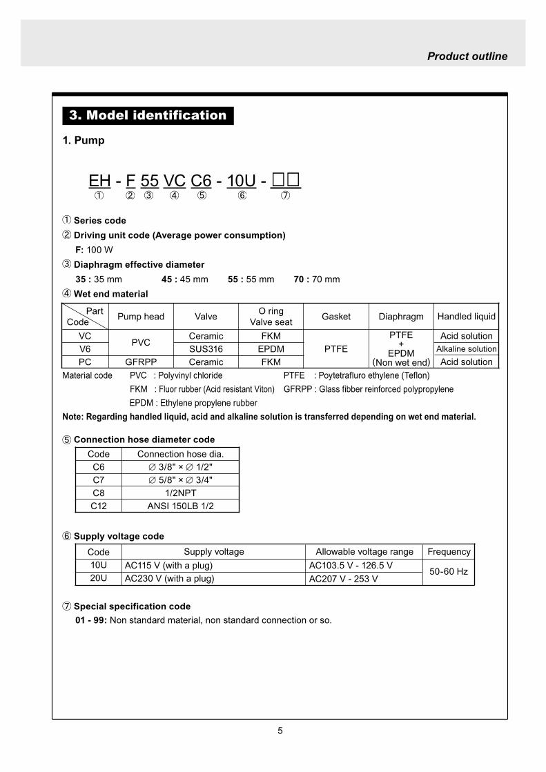
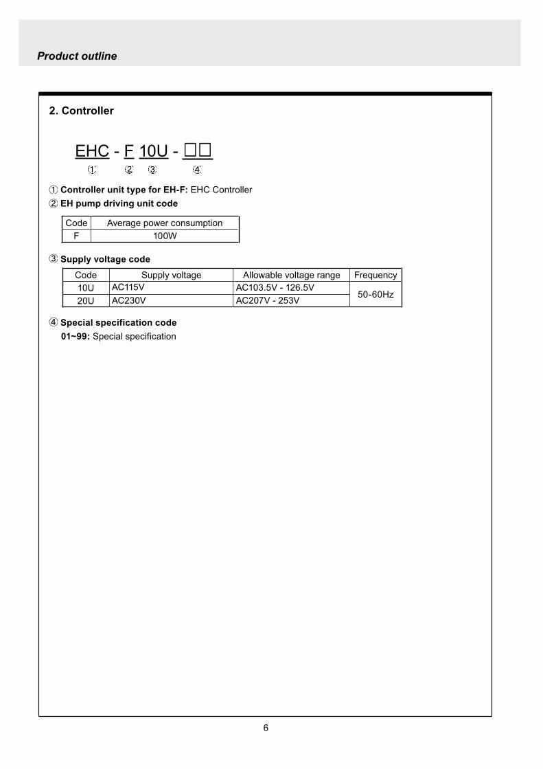
6
Product outline
2 Controller
EHC - F 10U -
Controller unit type for EH-F EHC Controller EH pump driving unit code
Supply voltage code
Special specification code 01~99 Special specification
Code Average power consumptionF 100W
Code Supply voltage10U AC115V20U AC230V
Allowable voltage range FrequencyAC1035V - 1265V
50-60HzAC207V - 253V
7
Product outline
4 Parts name
1 Pump parts
Pump headLock screw
Driving unit
Control panel
Control unit
Stroke lengthadjusting knob
Socket cord
MAN DIV MULT ANAR V
OVER P12 LOCK Err SET
spm
mA
LED lights orange when Pre-STOP signal comes from level sensor or lights redly when STOP signal comes
Screen indicates operation states and setting values in figures and letters
StartStop key is used tostartstop pump operation
EXT keyis used to start pumpingin EXT operation mode
ON lamp lights as turning on power and blinks synchronously with each stroke
Up key is used to increase the setting values and to change the setting items Pressing Up and Down key at once can have the pump running at full spm
Down key is used to decrease the setting values or to change the setting items Pressing Up and Down key at once can have the pump running at full spm
2 Control unit
8
Product outline
5 Specification
1 Pump specification
2 Control unit specification
Operationmode
MAN (Manual operation) 1 - 240 spm
EXT
DIV (Pulse dividing) 1 - 9999MULT (Pulse multiply) times1 - 9999ANA R (Analog rigid) 4-20 0-20 20-4 20-0 mAANA V (Analog variable) 2 points in a range of 00-200 mA 0 - 240 spmEXT mode consists of the above 4 modes
Display
LCD 14 seg 5 digits spm Operational states and Settings
LEDON Green Lights as turning power on
Blinks synchronous with each strokeSTOP OrangeRed Lights orange when Pre-STOP is activated or lights redly when STOP is activated
Operation 4 keys STARTSTOP EXT UP DOWN
Control function
STOP Pump keeps running when Pre-STOP is activated or stops when STOP is activated
Self priming Pump operates at full speed when both Up and Down keys are depressed together
Key lock Lock and release key padsBuffer memory ONOFF setting is changeable (Initial setting is OFF)
InputPulse No-voltage contact Maximum 100 HzCurrent Range of DC0 - 20 mA (Input resistance 200 Ω)Level sensor Potential free contact or open collector 2-step contact
Output Photo MOS Relay ACDC 24 V 01 Aspm synchronous output The maximum input pulse frequency is 100 Hz however the maximum frequency is variable
depending on the setting of anti-chattering On-time of pulse requires 5 ms or more when ST 05 is selected
5060Hz
ModelsMax discharge
capacitymlmin(GPH)
Max discharge pressureMPa(PSI)
Stroke speed variable range
spm
Stroke length variable range
mm()
Average power
consumption
W
Masskg
EH-F 1 - 240 09 - 225(40 - 100) 100
45 750(119) 07(102)55 1200(190) 045(65)
16
70 2000(317) 03(44)
35 500(79) 10(145)
Note 1 Performance is obtained by pumping clean water at ambient temp at a rated voltage2 Discharge capacity is the value at max discharge pressure (100 stroke length 100
stroke rate) When discharge pressure is low pump discharges liquid much more than the discharge capacity shown above
3 Permissible ambient temperature 0 ~ 40 deg C 4 Permissible liquid temperature VC V6 0 ~ 40 deg C PC 0~60 degC 5 Permissible voltage fluctuation Within plusmn10 of the rated voltage6 Ask us or our distributor for special cases such as transferring slurry liquid
9
Product outline
6 Operational function
1 Manual operation and keys are used to set the number of strokes between 1 and 240 spm The pump startsstops
operation by pushing START STOP key The number of strokes is adjustable in the both pump states of running and stop
ON
ON
OFF
ON ON
STARTSTOP key
Operation
Stop
Operation
Pump operation
External signals
ON
OFF
Pump operation
1 2 3 4 1 2 3 4 1 2 3 4
Set value 14 in dividing operation
2 Pulse dividing operationIn this mode pump runs in the dividing operation for external pulse signals Dividing ratio is variable within the setting range between 9999 1 and 1 1 The upper limit of the number of strokes in the pulse dividing operation is equivalent to the maximum number of strokes in manual operation When the input signals over the upper limit stroke speed is incoming the residual signals can be stored up to 65535
External signals
Pump operationON
OFF
Set value 4 in multiply operation
1 2 3 4 1 2 3 4 1 2 3 4
3 Pulse multiply operationIn this mode pump runs in the multiply operation between 1 and 9999 times for an external pulse signal and stops automatically The number of strokes in the pulse multiply operation is equivalent to the number of strokes in manual operation The incoming pulse signals during the multiply operation motions are cancelled and are stored up to 65535
10
Product outline
4 Analog control operation ANA R(analogue rigid) mode
Pump operates within the range of 0-240 spm in proportion to the external signals between 0-20 mA4 (4-20 20-4 0-20 20-0) patterns are provided and the pump operates within 0-240 spm in proportion to the external signals in each patternIn the 4-20 or 20-4 pattern a breaking detective function becomes active automatically The function stops the pumping operation below 4 mA And an error indication DISCN blinks on the display of con-trol unit When this function is active check wiring This function can be released with STARTSTOP key
42
3
1
Num
ber o
f stro
kes
240
0 4 20
(spm)
Analog input(mA)
Conditions
The left graph is in the following patterns 4 - 20 20 - 4 0 - 20 20 - 0
240220
60
0 6 2017
(spm)
Analog input (mA)
P1
P2
Num
ber o
f stro
kes
Conditions
The left graph is in the following settingP 1 = 6 mA 60 spmP 2 = 17 mA 220 spm
ANA V(analogue variable) modePump operates within the range of 0-240 spm in proportion to the external signals between 0-20 mA Setting 2 points can draw a straight line Depending on the position of the 2 points 0 spm may not come at 0 mA in some cases When the stroke speed could become over 240 spm at some mA due to the set-ting pump speed is limited to 240 spm
11
Product outline
7 Control display instruction
1 Control unit
ON STOP
EXT
EH-F ControllerSTARTSTOP
DIVMAN
OVER P1 2 LOCK Err SETmA
spmMULT ANAR V
Manual operation indication (MAN)shows pump is in manual operation
indicationshows pump is running for self-priming at maximum stroke speed and calls userrsquos attention
mA indicationappears when setting amperage in EXT setting mode for analog control operation
SET indcationappears in user mode and EXT setting mode
Stop indicationappears during Pre-STOP or STOP signal input
Stroke speed indication appears when displayshows stroke speed
Pulse dividing indication (DIV)shows pump is in pulse dividing operation or pulse dividing ratio is being set
Pulse multiply indication(MULT) shows pump is in pulse multiply operation or pulse multiply ratio is being set
Display shows operational state and set values in figures and letters
STARTSTOP keyis used to startstop pump operationThis key is also used to confirm each set value in set modes and used to move to wait mode
EXT keyis used to start pump operation in EXT operation modes
Over indicationlights when incoming signals are surplus to 240 spm in EXT operation
P1 and P2 indicationsappear when 2 points(P1 P2) are set in ANA V(analog variable) mode for analog control operation
Lock indicationappears when keys are locked
ON lampappears as turning on power and blinks synchro-nously with each stroke
Error indicationappears when an error occurs
Analog control operation indication (ANA R ANA V)ANA R indicates pump is in analog rigid operation or setting mode ANA V indicates that pump is in analog variable operation or setting mode
Down key is used to decrease the setting values and to change the setting items Pressing Up and Down key at once can have the pump running at full spm
Up key is used to increase the setting value and to change the setting items Pressing Up and Down key at once can have the pump running at full spm
12
Product outline
2 Typical indications
3 Warning indications
Indications Show
Pump is operating in the manual operation modeThe display shows the set spm
Pump is operating in the analog control mode(ANAV) of the EXT operation Display indicates 168 spm
The stroke speed is being set while pump is operating in the multiply operation(MULT)
Pump is being stopped via STOP input while operating in the dividing operation(DIV)
MAN spm
LOCK SET mA
MAN ANA V spm
MULT
SET
DIV spm
Indications shows
Key lockAll the key operation can be ineffective in order to prevent any per-son other than user from operating the pump This function can be active by pressing STARTSTOP key for 5 seconds in any pump states and LOCK indication appears Key lock function can be released by pressing STARTSTOP key for 5 seconds when LOCK indication appears on the display
The left indication appears when input signal is below 4 mA with the 4-20 or 20-4 pattern in ANA R (Analog rigid) mode In this state pump is under suspensionBy pushing STARTSTOP key once this error is released and the mode moves to waiting mode Check wiring and signals
OVER indication appears when incoming signals are surplus to 240 spm in EXT operation
MAN spm
LOCK SET mA
ANAR
Err
spm
MAN spm
OVER
13
Installation
1 Before installation
Working without disconnecting the power supply may cause an electrical shock Before engaging upon any working procedures involving the pump be sure to turn the power supply switches off to stop the pump and the related devices
Upon becoming aware of a dangerous sign or an abnormal condition while engaging on the installation terminate the work immediately and start it from the beginning again
Do not operate the pump on the voltage which is not specified on the nameplate Failure to do so may result in damage or a fire Be sure to earth the pump
Do not place any dangerous materials or flammable objects near the pump for the sake of safety
WARNING
CAUT ION
1 Dropping the pump or subjecting it to a strong impact may result in the faulty performance Handle the pump with care Do not use the damaged pump for the prevention of the electri-cal leak or shock
2 When installing pump avoid the places where the pump is exposed to the direct sunlight the ambient temperature is above 40 digC or the relative humidity is above 85 Though the pump has a simple waterproof and dust-proof structure it is recommended to protect the pump with a cover when installing it outdoor
3
Installation
14
3 Select a level floor and use the four M6 bolts to firmly anchor the pump so as not to allow any vibration If the pump is inclined the discharge amount may decrease considerably
4 Pump should be installed in a well-ventilated place in summer and free from freezing in win-ter
6 Place the pump as close to the suction tank as possible realizing a flooded suction system (It is recommended the pump should be located lower than the suction-side tank)
7 If the pump is used to feed some liquid that gen-erates air bubbles easily (sodium hypochlorite hydrazine solution etc) the system must be positioned in a cool dark place away from direct sunlight If a tank is installed realize a flooded suction system
5 Select the installation site convenient for the future maintenance and inspection
2 Precaution for piping Piping vibrates due to the pulsation from pump Piping should be supported in order to prevent the vibra-
tion Install an air chamber or an accumulator to reduce the pulsation Ask us for further information Be careful not to have hose bend when arranging tubing It is recommended to arrange the short piping as much as possible The longer piping length the more
pressure drops and can exceed the allowable pressure of pump and can cause the over feed phenom-enon
It is recommended an automatic air bleed valve or a pressure relief valve should be installed in order to release the pressure of discharge piping for maintenance
It is recommended to install a relief valve on the discharge side piping that releases pressure automati-cally
Install a pressure gauge on the discharge side piping in order to measure the pressure inside the piping When installing EH-F pump with the flange connections or the union connections be sure to have the
connections on the discharge side fixation on wall pillar or the frame of equipment for the prevention of vibration Make sure that the piping is fixed as well
CAUTIONIncomplete fixation of pump and piping can lead to the damage to these products Significant vibration often results from the incomplete support for the discharge side connection of pump In case the direct support for the flange or union connection can not be secured try to support pump close to the discharge connection as much as possible
15
Installation
Check valve
Air bleedValve
Discharge hose
Pump
Tree way joint
Accumulator
Drain valve
Discharge valve
Back pressure valve
Pump
Suctionvalve
Air bleed valve
Airchamber
Pressure gauge
Relief valve
3 Piping1 Recommended piping drawings
Arrange piping to meet the suction and dis-charge requirement Especially pay attention to piping arrangement in case of handling the slurry which has settling property
Installation
16
Hose
Hose stopper
Fitting spacer
O ring
Fitting nut
Place hose stoppers with R surfaceface to face with fitting spacer
Hose
Hose stopperFitting spacer
O ring
Fitting nut
Fitting
Suction port
Pump head
2 Piping arrangement1 For hose connection first fit a fitting nut and then a
hose stopper and a fitting spacer in the last place If the hose stopper is not fitted properly leakage may occur and suction amount may decrease
The hose end should be secured by a hose stop-per Insert a hose end into a fitting spacer via a fitting nut and a hose stopper Then squash the hose end between the hose stopper and the fit-ting spacer Finally screw the fitting nut in
The hose stopper should be placed with its R surface face to face with the fitting spacer An incomplete hose stopper fixation or a reverse hose stopper placement can lead to leakage or insufficient suction
CAUTIONReverse hose stopper placement can dam-age hose
Fitting nut is made of plastics The fitting nut may break when it is tightened excessively
If attached hose is not long enough prepare a substitute hose such as chloroethene braided hose and polyethylene hose with a suitable bore to the hose fitting spacer
CAUTIONIt is very dangerous to attach the different size hose It may come off
Insert the fitting spacer into hose as deep as possible If the insertion is not enough hose may come off and leakage may result
Be careful not to lose the attached O rings Leakage or suction failure may result without an O ring
2 Hose connection tends to loose if liquid or ambient atmosphere is higher than normal temperature Re-tighten the fitting nut properly after starting opera-tion Be careful not to tighten the nuts too much
3 When fitting the hose again after detaching it for maintenance cut the end of hose off about 10 mm and insert it
17
Installation
4 Check valveEH-F35 45 (VCV6PC) types are attached with a check valve Fit the check valve to piping in the fol-lowing cases
1 The suction side liquid level is higher than the dis-charge side liquid level (Fig A) When injection point is below the liquid level of suction side at atmospheric pressure
2 The suction side pressure is higher than the discharge side pressure (Fig B)
3 The discharge side liquid level is higher than the suction side liquid level but the differential height between both liquid level is 5 m or below (Fig C)
4 The loading pressure of piping resistance and dis-charge head to the pump is under 013 MPa
Suction side Discharge side
Figure A
Figure B
5m
Figure C
To chemical tankor vessel
Remove check valve
3 Piping for bleedingPrior to bleeding disconnect hose and point a hose end at a suction tank or vessel Remove a check valve if it is attached on the discharge side piping
18
Installation
R12
Oslash12
5 Check valve mounting1 Tap the female thread of NPT12 at an injection
point Check valve is provided with the male thread of R12 Cut off the unused portion to fit it on a pip-ing
2 Apply seal tape on the threaded portion of the check valve and screw it in the injection point Pinch the check valve body lightly with a spanner and tighten it for easy mounting
3 When fitting a hose into a check valve with the check valve on main pipe tighten the fitting nut holding the check valve body by hand
4 Cut the end of check valve(empty 12) accordingly when mounting it in a small pipe It is recommended the end of the check valve comes at the centre of pipe bore
It is recommended to mount a check valve via a valve for maintenance Provide NPT12 female thread and screw it in Valve should be resistant to the chemical liquid in use
Valve
Check valve
Check valve body
Apply seal tape
Fitting nut
Pipe
Cut the end nozzle offif it is too long compared topipe bore
6 Flange connection and union connection1 Flange units and union sockets are packed apart from pump body Fit the flange units or the union sockets to
pump body before use Refer to the following figures2 Secure the sealing by fitting O rings to each connection
CAUTIONWhen mounting flange units or union sockets to pump body be careful not to allow O ring to get out of the groove Especially pay attention to the O ring on the groove on suction side
3 Fix the flange units or the union sockets to the pump body by tightening fitting nuts In this case first tighten the fitting nuts by the hand and then re-tighten it by 90 degrees with a spanner
CAUTION
Fitting nut is made of plastics The fitting nut may break when tightened excessively
Flange connection type
19
Instillation
Flange
Flange
Fitting nut
O ring
O ring
Elbow
Pump body
Fitting nut
Drain
Discharge
Air chamber
7 Accumulator and air chamber mountingInstall an accumulator or an air chamber on piping for the prevention of the vibration from the pulsation of pump discharge hose
20
Installation
8 Piping (General notes)1 Keep piping short and less bends Do not make the projections where air can remains
2 Support piping to avoid having the pump subject to the piping weight especially when wet-end mate-rial is made of PVC
3 In case of transferring the slurry which tends to settle do not make U shape on piping A drain plug is required at the lowest portion of piping as well
4 In case of transferring the viscous or toxic liquid or the liquid which tends to settle provide the piping for cleaning for the purpose of maintenance
5 In case of transferring the high temperature or low temperature liquid the telescopic motion of piping from temperature variation should be taken into consideration
6 Select pipe materials based on a through examination of the corrosive resistance and the estimated pressure applied to piping
7 Do not allow any adhesive agent to get in pump when connecting PVC-made pipe on the discharge side piping
8 Clean the inside of piping before installing pump in it
9 A relief valve is required to protect pump and piping Install a relief valve on the discharge piping near the pump
9 Suction piping1 Regarding suction piping a flooded suction system should be realized The bore of suction piping is
recommended to be larger than that of pump suction port
2 Each joint of suction piping needs to be mounted carefully in order to prevent air from coming in Air influx into piping may cause discharge performance failure and instability
10 Discharge piping1 Mount a relief valve on the discharge piping near pump A discharge valve should be mounted beyond
the relief valve
2 The pressure resistance of discharge piping should be higher than the set pressure of relief valve Mount each joint carefully
21
Installation
4 Electrical wiring
1 Power cord connection
Electrical works and the handling of power source must be done by qualified person
Do not operate pump with the wet hand
Make sure that power is not turned on while working on wirng
Do not dismantle electronic circuit
Electronic circuit may be broken Never apply other voltages than a rated voltage
WARNING
CAUT ION
High power equipment
CAUTION Avoid sharing a power source with a high
power equipment This can lead to the fail-ure of the electronic circuit of control unit due to extremely large surge voltage
The noise from an inverter can cause fail-ure
22
Installation
P
Surge absorption element
PNoise cut transformer
CAUTION
2 Wiring procedure
Electronic circuit of control unit may be failed by extremely large surge voltage Do not use the pump near to the high power equipment of 200V or more which may generate large surge voltage If the use of high power equipment is inevitable take either of the following measuresa Install a surge absorption element such
as varister with 2000A or more durability on the power point
b Install a noise cut transformer
CAUTION
Only qualified operatorsservice staff should be in charge of the related electrical arrange-ment and control of the power source Failure to observe this instruction may result in injury to person or damage to assets
Never connect wires while power is turned on otherwise an electrical shock or a short-circuit of controller may result Be sure to turn off power before wiring
Internal circuit is still electrified right after turning off power Take 1 minute or more to start wiring
Do not band a power cable either electrical wires or relay output wires
Earthing wire is equipped with a jumper pin Keep the jumper pin equipped in use
Do not combine the EXT or STOP signal line with a power cord or a power cable Do not com-bine power source line with the EXT or STOP signal line by a concentric cable (5 wires cable or so) Otherwise noise come about through EXT and STOP wires due to the induction effect from power cable and it may results in wrong operation or the failure of pump
Regarding frequent ON-OFF operation it is recommended to stop pump thorough STOP input terminal but not by connecting or disconnecting power source When connecting and discon-necting power cord can not be avoided it should be within 6 times an hour
23
Installation
Procedure to connect the signal cordUse DIN connector of five poles and four polesThe following connectors made by Binder in Germany are recommendedAsk IWAKI for the detail of Binder connector 5 poles 713 series 99-0436-10-05 for input signal 4 poles 715 series 99-0430-15-04 for level sensor
The following connector made by Hirschmann in Germany is recommendedAsk IWAKI for the detail of Hirschmann connector 4 poles GDS307 for output
The following procedures are based on the connector made by Binder and HirschmannIf a similar connector is used the wiring should be made according to the instruction manual of the manufacturer of connector
In case of Binder connector(1) Dismantle the connector and pass the wire through it Outer diameter of the cable should be oslash4-6
Using the different cable in diameter the connector can not be sealed properly
(2) Strip the cable ends and insert wire to the appropriate positions and connect them with screwsThe maximum allowable cross section of the wire is 075mm2
(3) After connecting the wire assemble the connector securely Slightly pull the cord to confirm that the cord connection is secured Perfect sealing can not be obtained unless the cord connection is loose
24
Installation
In case of Hirschmann connector(1) Dismantle the connector and pass the wire through it Insert a minus screw driver into the place shown by
ldquoLIFTrdquo and lift it up Outer diameter of the cable should be 35-6 mm Using the different cable in diam-eter the connector can not be sealed properly
(2) Strip the cable ends and insert wire to the appropriate positions and tighten them with screwsThe maximum allowable cross section of the wire is 075mm2
(3) After connecting wire assemble the connector securely Slightly pull the cord to confirm that the cord connection is secured Perfect sealing can not be obtained unless the cord connection is loose
Terminal position
NA Not Applicable
Connection of level sensorThe controller corresponds to two stage level sensor Connect the pre-alarm signal to Pre-STOP and the alarm signal to STOP When the pre-alarm signal comes in the orange lamp lights but the pump does not stop When a contact type is used connect wires to STOP and COM2 For open collector output level sensor Pay attention to the polarity Pre-Stop and STOP are plus (+) and COM2 is minus (-) (Max charged voltage 5V Current 18mA) For contact output level sensor Use the one designed for electronic circuit and the minimum applicable load of 1mA or less
Connection inside connector 1 STOP 2 Pre-STOP 3 Free 4 COM2
1
2
3
4 CLOSE
ON
PUMP
Level Sensor(STOP)
OPEN
Pulse
COM
+12VDC
NA
ANA(4-20)
Pre-STOP
STOP
COM
NA
OUT
25
Installation
Stop functionStop function is the function to stop the pump by the external signal Connect the wires to STOP and COM2 in the same way as the level sensor connection
CAUTION
Frequent stop and start of pump should be done by using STOP function (ON and OFF of STOP terminal) If you can not use STOP function and are forced to operate pump by turning OFF and ON of power source ON and OFF of power source should be limited to six times an hour
Pulse signal inputPulse signal input is used when the pump runs in the DIV or MULT of EXT modeDIV means dividing and MULT means multiply In case of open collector signal Pay attention to the polarity Pulse is plus (+) and COM1 is minus (-) (Max charged voltage 5V Current 18mA) In case of contact signal Use the one designed for electronic circuit and the minimum applicable load of 1mA or less
Connection inside connector 1 Free 2 Pulse 3 Free 4 12VDC 5 COM
3
2
4
15
Analog signal inputAnalog signal input is used when the pump runs in ANAR or ANAV of EXT modeANAR means analog rigid and ANAV means analog variable
Connection inside connector 1 ANA 2 Free 3 Free 4 Free 5 COM
3
2
4
15
26
Installation
Output signalOUT Photo MOS relay outputStandard is output synchronous with stroke Output is activated synchronous with each pump stroke
Connection inside connector 1 OUT 4 OUT
OUT 1
2
34
Surge voltage The electronic circuit of the control unit may be affected by excessively high surge voltage Do not operate the pump near the high-power elec-trical equipment of 200V or above that generates high surge voltage Under unavoidable circumstances take either of the following measures(1) Use a surge absorbing element (such as a
varistor with the surge resistance of 2000A or more) at the pump power supply connection
(2) Use a noise-cut transformer
Surge absorbing element
Noise-cut transformer
1 Preparation for pump operationBefore pump operation check that
bull Liquid tank is filled enough Supply liquid if it is less than the required levelbull There is no liquid leakage or congestion due to breakagebull Both suction and discharge side valves are openedbull Pump is connected to the predetermined power source correctlybull Electrical wiring is correct and there is no possibility of a short circuit or current leakage
2 BleedingBleeding is a process to eliminate the air inside the suction-side piping Be sure to carry out an air elimi-nation prior to initiating the pump operation after replacing the liquid inside a tank and after a long peri-od of storage Air gushes together with chemical liquid when carrying our bleeding For safety reasons first turn the end of a bleeding hose to a tank or a container
CAUTION
Some liquids may cause skin trouble or affect the quality of mechanical parts Wipe off chemi-cal liquid immediately when they splash on the hand or mechanical parts
27
Operation
1 Pump Operation
WA R N I N G Wear protective clothing
Wear protective clothing such as a protective mask safety gloves or so when handling chemical liquid
Do not operate pump with a discharge-side valve completely closed Operating the pump with the discharge-side valves fully closed may cause the liquid spillage or
the extremely high pressure inside the pump or the discharge-side pipingtubing This could lead to a piping burst Be sure not to operate pump with the discharge-sides valve closed
CAU T I O N A long time dry running (longer than 30 minutes) may cause the pump overheat and it could lead
to the deformation of the pump unit consists of a pump head and valve cases or so or may loosen the pump head fitting and result in liquid leakage
If the hex socket cap bolts on a pump head are loosened liquid leakage may resultBe sure to fasten all the 6 or 8 hex socket cap bolts tightly before starting the initial pump opera-tion And periodically check the looseness of the bolts on the pump head and retight the bolts as necessary
bull Tightening torque255NbullmTighten all the bolts diagonally applying equal tightness
If electric wiring gets wet due to accidental liquid spillage fire or electrical shock may occur Never get it wet When the electric wiring gets wet turn off power and wipe the liquid away
A frequent ON-OFF operation should be conducted by using STOP function(ON - OFF signals to STOP terminal) In case the STOP function is not available for the ON-OFF operation the ON - OFF operation by turning onoff power should be limited to six times an hour
4
28
3 Procedure for bleeding
Check valve should be removed
To tank or drain pan
100
75
50
25
0 25 50 75 100
(Fixed stroke length)
Stroke length adjustment
240spm
180spm
120spm
Flow
rate
Operation
[1] Extend the tube connected to the discharge-side fitting nut of pump to a chemical tank or a drain pan Then start pump operationbull Remove a check valve if it is installed on dis-
charge-side
[2] Operate the pump for about 10 minutes to eliminate air completely
[3] When the air in pump head is completely eliminated and liquid is replaced return the discharge-side tube to the regular tubing position
[4] Finally make sure there is no leakage in any section
4 Discharge capacity adjustmentDischarge capacity can be adjusted by both the stroke length adjustment and the stroke rate adjust-ment but basically adjust it via the stroke rate adjustment Stroke length adjustment is an auxiliary way to cover the range where the stroke rate adjustment can not reachPay attention to the following for correct procedure
Stroke rate adjustment(1) For some liquids which diffuses gas such as sodium hypochlorite and hydrazine solution adjust discharge capac-
ity by means of the stroke rate adjustment with the stroke length about 100 Gas lock may occur if the stroke length is set to short
(2) When the back pressure on discharge side is high adjust discharge capacity by the stroke rate adjustment with the stroke length about 100
(3) In case reaction is greatly influenced depending on the discharge capacity per pump shot in the application of neutralization or titration adjust discharge capacity by the stroke rate adjustment with the shortened stroke length and reduce the discharge capacity per shot
1 Discharge capacity adjustment procedureAppropriate stroke length and stroke rate are decided on the pump operating condition and liquid characteristics Following ways are recommended for proper calibration
(1) Set stroke length at 100 and roughly adjust discharge capacity by adjusting stroke rate
(2) Measure discharge capacity(3) If the measured capacity is below the wanted value
increase the stroke rate and measure again the dis-charge capacity
(4) Adjust stroke length for the fine adjustment of discharge capacity(5) Determine a discharge capacity at the last and confirm the wanted capacity is discharged
CAUTION
29
100
75
50
25
0 60 120 180 240spm
Fixed stroke length
Stroke rate adjustment
Flow
rate
Screw driverOPEN
LOCK
100
75
50
25
0 25 50 75 100
Fixed stroke rate
Flow
rate
Stroke length adjustment
Operation
2 Stroke rate adjustmentStroke rate is adjusted by the key operations of control unit Control the plunger stroke rate per minute from 1 to 240 spm via control unit
3 Stroke length adjustmentStroke length adjustment knob is locked with a screw Loosen the screw before adjustment and lock it afterwards
(1) Turn on pump and adjust the discharge capacity by turning the stroke length adjusting knob while pump is running
(2) The left graph shows the relation between stroke length and discharge capacity The maximum dis-charge capacity is shown on the name plate
bull The usage between 40 and 100 is practi-cal
Do not turn the stroke length adjusting knob when pump stops
CAUTIONBe sure to tighten the screw on the adjust-ment knob after an adjustment The knob may rotate unintentionally due to a loose fixation This may result in the fluctuation in a discharge rate
30
Mode ParameterDefault value
Setting range Step
Manual operation Stroke speed 240 1-240DIV setting Dividing ratio frasl 1 1-9999
MULT setting Multiply ratio times1 times1-9999ANA R setting 4-20 4-20 20-4 0-20 20-0
ANA V setting
P1 amperage 40 00-200P1 stroke speed 0 0-240P2 amperage 200 00-200P2 stroke speed 240 0-240
User setting
EXT operation ANA V DIV MULT ANA R ANA V
Anti-chatteringMECH MECH ELECST05 ST05 ST20 ST50FT01 FT02 FT04
Buffer memory MEM-N MEM-N MEM-Y
111-
011
011
2 Control unit operationEH-F type pump is controlled by means of setting or changing the setting values of the controller Control functions are various at each operation mode Read this section carefully before operation
Default parameter values
5 Full operationPut pump in use after bleeding and adjusting discharge capacityPump runs in manual operation or in accordance with the setting of control unit
6 Manual operationStarting pump After turning on power ON lamp (Green) appears and display shows WAIT mode For
the first time to turn on power MAN lamp appears and pump starts after pushing STARTSTOP key once
Stop pump Push STARTSTOP key to turn off MAN lamp and stop pump Pump starts and stops every time STARTSTOP key is pressed
7 EXT operationRefer to the next section of 2 Control unit operation
8 Shout down When pump will not in use for a long time (one month or more)
Run pump with clean water about 30 minutes in order to clean the wet-end parts and the inside of pip-ing before storage
When re-starting pump after a long time storage If pump dose not suck up liquid clean valve sets and remove the sticking foreign matters Carry out an air elimination and adjust discharge capacity when air stays inside pump head Refer to page 28 3 Procedure for bleeding
Operation
---
-
31
AN
A V
(Ana
log
var
iabl
e)
DIV
(Pul
se d
ivid
ing)
MU
LT(P
ulse
mul
tiply
)A
NA
R(A
nalo
g ri
gid)
SE
TS
ET
Use
r mod
e
EX
T m
ode
sele
ctio
n
EX
T
EX
TE
XT
EX
TE
XT
EX
T EX
T
EX
T
EX
T
EX
T
EX
T
EX
T
EX
T
EX
T
EX
T
EX
T
EX
T
EX
T
3 sec
onds
or m
ore
Wai
t mod
e
Set
ting
of fi
xatio
n pa
ttern
EX
T m
ode
Man
ual o
pera
tion
Set
ting
of s
troke
num
ber
AN
A R
(Ana
log
rigi
d)M
ULT
(Pul
se m
ultip
ly)
DIV
(Pul
se
div
idin
g)
AN
A V
(Ana
log
var
iabl
e)
anti-
chat
terin
gse
tting
dis
play
Setti
ng o
f div
idin
g ra
tioS
ettin
g of
cou
nt n
umbe
r
Curre
nt va
lue of
P1
Stro
ke nu
mbe
r of P
1
Curre
nt va
lue
of P
2
Stro
ke nu
mbe
r of P
2
EX
T O
pera
tion
Dis
play
EX
T se
tting
mod
e
Buf
fer m
emor
yse
tting
dis
play
Pow
er O
N
spm
MA
Nsp
m
spm
DIV
DIV
SE
TS
ET
MU
LT
MU
LTsp
mA
NA
V
spm
AN
AR
AN
AR
SE
Tm
AS
ET
mA
spm
AN
A
V
P1
mA
SE
T
spm
AN
A
V
P1
AN
AR
SE
Tm
A
AN
AR
SE
Tm
AS
ET
AN
A
V
P 2
SE
T
spm
AN
A
V
P 2
AN
AR
SE
Tm
A
AN
A
V
SE
TS
ET
SE
T
SE
T
SE
T
SE
T
SE
T
SE
T
SE
T
SE
T
SE
TS
ET
1 Overview Operating Scheme
Operation
1 means automatic transfer WAIT mode is selected when the power is switched on for the first time On and after the initial power activation pump restores the previous status right before the power is switched off
2 Regarding MANUAL mode pump starts operation by pushing STARTSTOP key at WAIT modePushing STARTSTOP key again the pump stops and returns to WAIT mode
3 Regarding EXT operation pushing EXT key at WAIT mode the pump moves to EXT mode and starts operationPushing STARTSTOP key stops the operation and returns the pump to WAIT mode
4 The change of each setting of EXT operation is accessible by pushing EXT key at EXT mode Pushing EXT key after the setting pump starts in EXT operation according to the changed setting
5 Pushing EXT key for 3 seconds at WAIT mode pump moves to USER mode At USER mode the EXT mode selection and the detailed setting such as the setting of buffer memory or so can be obtained
For details refer to each section of 2 Pump operation
2 Pump operation1 Operation of controller
Before turning on power confirm the specified power source on the nameplate
CAUTION
Connecting any other powers than the one shown on nameplate to pump is strictly prohibitedIt could lead to pump trouble or failure
Operation
32
1 Turning on powerDisplay shows WAIT mode when pump is turned on for the first time After the initial power activation the pump restores the previous mode right before the power was turned off last time If power is turned off at any setting modes WAIT mode appears at the next power activation
Stroke speed setting value is shown on display at WAIT mode ON lamp lights (Green)
EXT
EH-F ControllerSTARTSTOP
ON STOP
spm
33
2 Manual operation(1) Stroke speed can be adjusted by and
keys The figure changes quickly when either or key is depressed The picture below
shows the stroke speed is set to 160 spm
EXT
EH-F ControllerSTARTSTOP
ON STOP
spm
EXT
EH-F ControllerSTARTSTOP
ON STOP
MAN spm
EXT
EH-F ControllerSTARTSTOP
ON STOP
spm
(2) Push STARTSTOP key once to start the pump operation MAN indication appears and ON lamp blinks synchronously with each stroke
(3) MAN indication disappears and ON lamp stops blinking as STARTSTOP key is pushed again Pump enters WAIT mode
Operation
Operation
34
EXT
EH-F ControllerSTARTSTOP
ON STOP
ANA V
P1 SET mA
EXT
EH-F ControllerSTARTSTOP
ON STOP
P1 SET
ANA V spm
EXT
EH-F ControllerSTARTSTOP
ON STOP
spm
EXT
EH-F ControllerSTARTSTOP
ON STOP
ANA V spm
(4) Set the current value at P1 Figure increases or decreases as or key is pushed The pic-ture below shows 80 mA is set to point 1
EXT
EH-F ControllerSTARTSTOP
ON STOP
ANA V
P1 SET mA
(5) Pushing EXT key once spm appears on the display while mA disappears The picture below shows the number of strokes at P1
EXT
EH-F ControllerSTARTSTOP
ON STOP
P1 SET
ANA V spm
3 EXT operation (ANA V mode)(1) Push STARTSTOP key to move to WAIT mode
if pump is in another mode Go to next step if pump is in WAIT mode
(2) ANAV indication appears and pump enters an EXT mode as EXT key is pushed once Pump starts operation in accordance with current sig-nals and various settings ON lamp blinks at each pumping during operation Pump is con-trolled via the EXT mode which was select-ed at USER mode The initial setting of EXT mode is ANA V mode Select a preferable EXT mode in USER mode The picture below shows ANA V mode (The spm on the display changes according to input signals)
(3) Push EXT key once when pump is running in ANA V mode Display indicates the setting display of ANA V mode spm indication dis-appears and P1 SET and mA indications appear on the screen
(6) Set the number of strokes at P1 Figure increasesdecreases as key is pushed Picture below shows 10 spm is set for point 1
Operation
35
(7) Push EXT key to move to the setting display of the current value at P2 P1 and spm disap-pear and P2 and mA appears instead
EXT
EH-F ControllerSTARTSTOP
ON STOP
ANA V
P 2 SET mA
EXT
EH-F ControllerSTARTSTOP
ON STOP
ANA V
P 2 SET mA
EXT
EH-F ControllerSTARTSTOP
ON STOP
P 2 SET
ANA V spm
(11) Push EXT key to return to EXT mode Pump starts to run in ANA V mode on the setting of (4) through (10) ON lamp starts to blink at each pumping
EXT
EH-F ControllerSTARTSTOP
STOPON
ANA V spm
EXT
EH-F ControllerSTARTSTOP
ON STOP
P 2 SET
ANA V spm
EXT
EH-F ControllerSTARTSTOP
ON STOP
spm
(8) Set the current value of P2 by pushing and keys Picture below shows 180 mA is set to
point2
(9) Pushing EXT key once spm appears on the display while mA disappears The picture below shows the number of strokes at P2
(10) Set the number of strokes at P2 by pushing and keys Picture below shows 200
spm is set to point 2
(12) Pushing STARTSTOP key pump enters WAIT mode and pump stops ON lamp stops blink-ing and ANAV indication disappears
CAUTIONWhen the setting of the buffer memory is OFF keep the number of strokes in the dividing operation 240 spm or below The input signals to operate the pump over 240 spm can cause an unstable pump operationWhen the setting of the buffer memory is ON the pump operates for all the input pulse signalsPump keeps operating after all the signals are stopped in this case Be careful when setting of buffer memory
Operation
36
EXT
EH-F ControllerSTARTSTOP
ON STOP
DIV
SET
EXT
EH-F ControllerSTARTSTOP
ON STOP
DIV
SET
EXT
EH-F ControllerSTARTSTOP
STOPON
DIV spm
EXT
EH-F ControllerSTARTSTOP
ON STOP
spm
(2) Pushing EXT key DIV appears and pump starts operation in the ratio of input pulse sig-nals a pumping ON lamp blinks synchronous-ly at each pumping The initial setting of EXT selection is ANA V mode Change mode to DIV mode via USER mode Refer to P 40 for detail information
(3) Push EXT key while pump is operating in DIV mode Pump stop running and SET indication appears on the DIV setting display in stead of spm indication
(4) Enter a dividing ratioFigure increasesdecreases when key is pushed The picture below shows 10 is set
4 EXT operation (DIV mode)
(1) Push STARTSTOP key to move to WAIT mode if pump is in another mode Go to next step if pump is in WAIT mode
CAUTIONOn condition the setting of buffer memory is OFF do not input any pulse signals during the pumping motions for a input pulse signal in the multiply operation These input pulse signals are cancelledWhen the setting of buffer memory is ON pump operates for all the input pulse signals
Operation
37
EXT
EH-F ControllerSTARTSTOP
ON STOP
spm
EXT
EH-F ControllerSTARTSTOP
STOPON
DIV spm
EXT
EH-F ControllerSTARTSTOP
ON STOP
spm
EXT
EH-F ControllerSTARTSTOP
ON STOP
MULT
(5) Push EXT key to return to EXT operating mode Pump starts to run on the setting at item (4) ON lamp blinks synchronously at each pumping
(6) Pushing STARTSTOP key pump enters WAIT mode and pump stopsDIV indication disappears and ON lamp stops blinking
5 EXT operation (MULT mode)
(2) MULT indication appears and pump starts running in an EXT operation mode in the ratio of an input pulse signal pumpings as press-ing EXT key ON lamp blinks at each pump-ing Display shows the rest of the number of strokes In MULT mode the number of strokes is equal to the setting value in manual opera-tionThe initial setting of the EXT mode selection is ANA V mode which is the operation in pro-portion to current First select MULT mode via USER mode Refer to P 40 for detail informa-tion
(1) Push STARTSTOP key to move to WAIT mode if pump is in another mode Go to next step if pump is in WAIT mode
Operation
38
EXT
EH-F ControllerSTARTSTOP
ON STOP
spmEXT
EH-F ControllerSTARTSTOP
ON STOP
ANAR spm
EXT
EH-F ControllerSTARTSTOP
ON STOP
MULT
SET
EXT
EH-F ControllerSTARTSTOP
ON STOP
MULT
EXT
EH-F ControllerSTARTSTOP
ON STOP
spm
EXT
EH-F ControllerSTARTSTOP
ON STOP
MULT
SET
(5) Push EXT key to return to MULT mode(3) Pushing EXT key when pump is running in the multiply operation calls the setting display of MULT mode and SET indication appearsPump stops running and ON lamp stop blinking
(4) Enter the number of pumpings per input signalFigure increasesdecreases when key is pushed The picture below shows the pump-ing number is set to 1800 times per an input signal
6 EXT operation (ANA R mode)(1) Push STARTSTOP key to move to WAIT mode
if it is in another mode Go to next step if it is in WAIT mode
(6) Pushing STARTSTOP key recalls WAIT mode and pump stops spm indication appears in stead of MULT indication
(2) Pushing EXT key ANAR appears and pump starts running in the ratio of an input pulse sig-nal pumpings ON lamp blinks at each pump-ing The initial setting of the EXT mode selec-tion is ANA V mode which is the operation in proportion to current is selected First select ANA R mode in USER mode Refer to P 40 for more information
Operation
39
EXT
EH-F ControllerSTARTSTOP
ON STOP
ANAR
SET mA
EXT
EH-F ControllerSTARTSTOP
ON STOP
ANAR spm
EXT
EH-F ControllerSTARTSTOP
ON STOP
ANAR
SET mA
EXT
EH-F ControllerSTARTSTOP
ON STOP
spm
(4) Figure increasesdecreases when key is pushed The picture below is when it is set to 0-240 spm for 20-4 mA
(5) Push EXT key to return to EXT mode Pump starts to run on the setting at item (4) ON lamp blinks synchronously at each pumping
(6) When pushing STARTSTOP key pump enters WAIT mode and stops running ON lamp stops blinking and ANAR disappears
(3) Pushing EXT key when pump is running in the multiply operation calls the setting display of ANAR mode and SET and mA indications appear while spm disappears Pump stops running and ON lamp stops blinking
Operation
40
EXT
EH-F ControllerSTARTSTOP
ON STOP
ANA V
(5) Push EXT key to confirm the desired EXT mode Pump displays the EXT mode selection The picture below shows DIV appears to indi-cate DIV mode is selected
EXT
EH-F ControllerSTARTSTOP
ON STOP
DIV
EXT
EH-F ControllerSTARTSTOP
ON STOP
SET
EXT
EH-F ControllerSTARTSTOP
ON STOP
spm
EXT
EH-F ControllerSTARTSTOP
ON STOP
spm
EXT
EH-F ControllerSTARTSTOP
ON STOP
SET
7 USER settingThe setting of each function is changed in USER mode Have the pump entering WAIT mode in order to move to USER mode OUT (Output) is synchronous with spm and it can not be changed
7-1 EXT mode selection Any one of DIV (pulse dividing) MULT (pulse multiply) ANAR (analog rigid) or ANAV (analog vari-able) can be active in EXT mode The initial mode when shipped from factory is ANAV
(1) Push STARTSTOP key to move to WAIT mode if it is in another mode If it is in WAIT mode go to next step
(2) Press EXT key for more than 3 seconds to move to USER mode The picture below shows pump enters the EXT mode selection
(3) Pushing EXT key SET appears and display shows the mode currently set Picture below shows ANA V mode is selected
(4) Push or key to select a desired EXT mode The picture below shows DIV mode is selected
(6) Push STARTSTOP key to move to WAIT mode spm appears while DIV goes out
Operation
41
EXT
EH-F ControllerSTARTSTOP
ON STOP
spm
EXT
EH-F ControllerSTARTSTOP
ON STOP
ANA V
EXT
EH-F ControllerSTARTSTOP
ON STOP
SET
(3) Push key once
EXT
EH-F ControllerSTARTSTOP
ON STOP
(4) Push key again to move to the anti-chatter-ing setting display
EXT
EH-F ControllerSTARTSTOP
ON STOP
(5) Pushing EXT key display shows the mode cur-rently set and SET appears on it The picture below shows when MECH is selected
EXT
EH-F ControllerSTARTSTOP
ON STOP
SET
7-2 Setting of anti-chattering Anti-chattering function is settable against the incoming pulses during the DIV or MULT operation For the long chattering of mechanical contact such as relay set a large figure via MECH For the high speed (high frequency) chattering of the semi-conductor type contact such as transistor set a small figure via ELEC ST05 of MECH is initial setting
(6) Select MECH by or key for a mechani-cal contact And select ELEC for a semi-conductor contact The picture below shows ELEC is selected
(1) Push STARTSTOP key to move to WAIT mode if it is in another mode If it is in WAIT mode go to next step
(2) Press EXT key for more than 3 seconds to move to USER mode The picture below shows pump enters the EXT mode selection
Operation
42
EXT
EH-F ControllerSTARTSTOP
ON STOP
SET
(7) Push EXT key to display the current set state The picture below shows FT01 is selected
EXT
EH-F ControllerSTARTSTOP
ON STOP
SET EXT
EH-F ControllerSTARTSTOP
ON STOP
EXT
EH-F ControllerSTARTSTOP
ON STOP
spm
7-3 Setting of buffer memoryIn case pump operation can not catch up with the input pulse signals in DIV or MULT operation exces-sive pulse signals can be put in memory up to 65535 pulses However the excessive pulses can not be restored if once power is off or mode is changed
EXT
EH-F ControllerSTARTSTOP
ON STOP
spm
(2) Press EXT key for 3 seconds or more to move to USER mode The picture below shows the EXT mode selection display
EXT
EH-F ControllerSTARTSTOP
ON STOP
ANA V
(8) Set a large figure for the long chattering by or key and set a small figure for high speed (high frequency) chattering The picture below shows FT04 is selected
(9) Push EXT key to return to the anti-chattering setting display SET indication disappears
(10) Push STARTSTOP key to return to wait mode spm indication appears
(1) Push STARTSTOP key to move to WAIT mode if it is in another mode If it is in WAIT mode go to next
Operation
43
(3) Push key once
EXT
EH-F ControllerSTARTSTOP
ON STOP
(7) Push or key in order to set buffer memo-ry to ON or OFF Select MEM-Y to set it ON Select MEM-N for OFF setting The picture below shows when ON is set
EXT
EH-F ControllerSTARTSTOP
ON STOP
SET
(4) Push key once again
EXT
EH-F ControllerSTARTSTOP
ON STOP
(8) Push EXT key to return to the buffer memory setting display SET indication disappears
EXT
EH-F ControllerSTARTSTOP
ON STOP
(9) Push STARTSTOP key to return to WAIT mode spm indication appears
EXT
EH-F ControllerSTARTSTOP
ON STOP
spm
(5) Push key once again and the buffer memory setting display is shown
EXT
EH-F ControllerSTARTSTOP
ON STOP
(6) Push EXT key in order to display the current set state SET indication appears The picture below shows the buffer memory is set to OFF
EXT
EH-F ControllerSTARTSTOP
ON STOP
SET
Operation
44
8 Bleeding amp self-primingAt WAIT mode Manual operating mode and EXT operating mode pump operates at max speed tak-ing priority over any functions when both and keys are pushed at once Pump runs at max speed only when both keys are depressed Pump state returns to the previous mode once either or key is released Pressing and keys for 10 seconds keeps pump running at maximum speed In this state this fixation is released when pushing either or key once and pump returns to the previous mode
(1) When pump is running in ANAV mode
EXT
EH-F ControllerSTARTSTOP
ON STOP
ANA V spm
(2) Pump start to run at full speed when and keys are pressed at once Display shows
PRIME If either or key is released pump returns to the previous mode In this case pump returns to ANAV mode
EXT
EH-F ControllerSTARTSTOP
ON STOP
ANA V
(3) Pressing both and keys simultaneously for 10 seconds or more pump continues to run at full speed even if both keys are released In this case indication appearsPush either or key to release this state indication disappears and pump returns to the previous mode In this case pump returns to ANAV mode
EXT
EH-F ControllerSTARTSTOP
ON STOP
ANA V
Operation
45
10 Error display and release(1) In case Input signals fall to 4 mA or below while
4-20 or 20-4 is set to ANA R mode pump stops with DISCN blinking and Err on dis-play
(2) This error state can be released by push-ing STARTSTOP key and pumps enters wait mode In this case check the wiring and input signals
EXT
EH-F ControllerSTARTSTOP
ON STOP
ANAR
Err
spm
EXT
EH-F ControllerSTARTSTOP
ON STOP
spm
9 Key lockKey lock function is to prevent pump from being operated by some other person than user If STARTSTOP key is pressed for five seconds or more when pump is running or stops all key operations become ineffective with LOCK indication on display This function can be released by pressing STARTSTOP key for 5 seconds while LOCK lights
EXT
EH-F ControllerSTARTSTOP
ON STOP
MAN spm
LOCK
46
Do not conduct a maintenance work with the wet hands It can cause an electric shock
Before dismantling pump be sure to turn off power and check the pump is not electrified Do not
start a dismantlement work after stopping the pump by pushing the STARTSTOP key only Put up
the sign of ldquoMaintenance work is in progressrdquo in order to prevent a pump switch from turning on
unintentionally during the work Release the pressure of discharge piping and drain the liquid from
the wet end parts And then clean the inside of pump head
Wear protective clothing such as a protective mask globes goggles and chemical-proof wear
according to the handled chemical liquid during the work
WARNING
5 Maintenance
1 Trouble shootingTrouble Cause Troubleshooting
Pump dose not start Faulty wiring or disconnection in wiring Voltage is too low Failure in the electronic circuit of control unit
Pump dose not suck liquidDischarge amount is low
Air suction from suction piping Valve gasket is not installed Valve set assembling direction is wrong Pump is air-locked Pump stroke length is too short Suction-sidedischarge-side valve is clogged with
foreign matter Adhesion of valve onto valve seat
Discharge amount fluctuates
Liquid leaks
Key operation is ineffective Key is locked Release key lock
Pump doesnt run
Pump is in waiting mode Signals are not coming for EXT operation Pump is in EXT setting mode Pump is suspended with STOP
Move to operation mode Check wiring and correct the wrong part Move to EXT operating mode Release STOP function
Abnormal noise
Suction-sidedischarge-side valve is clogged with foreign matters
The sound absorption gasket is worn out Bearing is worn out Spring is damaged
Piping vibrates due to pulsation Bearing is worn out Spring is damaged
Install a accumulator or an air chamber The end of pump life span The end of pump life span
Suction-sidedischarge-side valve is clogged with foreign matters
Air is trapped in pump Overfeeding Diaphragm is damaged
Fittings are not tightly closed Pump head is not tightened Diaphragm is damaged O ring and valve gasket are not installed O ring is damaged
Correct wiring Inspect power source and provide measurement Replace the whole unit
Arrange piping again Install valve gasket Reassemble valve set Carry out air elimination Drive pump with 100 stroke length to prime liquid Then
reset stroke length Disassemble inspect and clean Disassemble inspect and clean
Tighten fittings Tighten pump head Replace diaphragm Install O ring and valve gasket Replace O ring
Disassemble inspect and clean
Carry out air elimination Install a check valve or a back pressure valve Replace diaphragm
Disassemble inspect and clean
The end of pump life span The end of pump life span The end of pump life span
Abnormal vibration
Input pulse can not be read Signals are not coming Anti-chattering setting is not proper
Check wiring and correct the wrong part Change the setting properly
Analog signal input can not be read
Wrong wiring Signals are over acceptable loaded resistance
Check wiring and correct wrong part The load resistance is 200Ω Use some devise which can
accept the load resistance
47
CAUTION Check periodically whether the bolts fixing pump head are tightened Tighten them as needed
The bolts fixing pump head may loosen in operation Tightening torque 255Nbullm
Maintenance
3
bull Tighten joint where leakage has occurredbull The excessive air bubbles in the discharged liquid mean air suc-
tion has been caused in system Examine the piping and tighten joint on where leaks
Is there liquid leakage or air suction at any joints on pump or piping
2 Maintenance and inspection
1 Daily inspectionPay attention to the following points during pump operation Stop pump immediately upon detecting abnormality and take measures according to the item Troubleshooting When wear parts come to the life time replace them by new ones
No
1
2
Check Point Description
Does pump lift liquid normally
bull Is liquid normally fedbull Is suction pressuredischarge pressure at normal levelbull Has liquid undergone quality change crystallization or solidifica-
tion
Abnormal noise or vibrationbull Abnormal noise or vibration may happen from the abnormal func-
tioning of pump
EXT setting can not be stored
After EXT setting STARTSTOP key is pushed for EXT by mistake
Push EXT key to operate pump in EXT mode
ldquoPRIME is kept indicated and other operations are inac-cessible
Self-priming function is active Push either or key to release the function
Analog signal input can not be read and DISCN indication appears
Wrong wiring or disconnection Check wiring and correct the wrong part Refer to page 45
for how to release an error indication
Trouble Cause Troubleshooting
48
Maintenance
2 Wear partsWear parts should be replaced in proper period for a long period of pump operation It is recommended that follow-ing parts are always ready for the replacementVC V6 PC P6 types
Parts Qty Life span
Pum
p he
ad
Valve set
EH-F35 EH-F45 EH-F55middot70
2sets
8000hours
Diaphragm 1
Refer to exploded view
Bac
k pr
essu
re v
alve
1
2
Che
ck v
alve
7 6 1
8 11 1
Diaphragm seat 1
O ring
Poppet check valve (With check gasket)
Check valve spring Spacer
Diaphragm
O ring
Note Durability of wear parts depend on the pumped liquid temperature and pressure Time to be replaced mentioned as above is the estimation obtained by continuous pump-ing of clean water at ambient temperature
8000hours
4000hours
49
3 Dismantlement and assembly
Getting wet with or coming in contact with chemicals and toxic liquid is harmful Wear protective clothing such as a protective mask globes goggles and chemical-proof wear during the work
Risk of electrical shock Be sure to turn off power and confirm that pump and devices are not electrified before the work
Release the pressure inside pump and a discharge hose by opening an air bleed valve on piping prior to loosening the piping connections or the dismantlement of pump Dismantlement with the pressure inside pump could lead to liquid spillage
Be careful not to touch residual liquid when dismantling pump Some liquids are harmful for skin or component parts Wipe off liquid when the hand or the component parts come in contact with liquid
WARNING
CAUT ION
Hose
Hose stopperFitting spacer
O ring
Fitting nut
Fitting
Pumphead
Remove the fittingwith a spanner
1 Valve set replacement Dismantlement1 Loosen a fitting nut and remove the hose con-
nected to pump head Pay attention to the liquid dripping
2 Loosen a fitting with a spanner to remove it Then detach the valve set from pump head
Maintenance
50
AssemblyAssembly procedure is in reverse order to disas-sembly Pay attention to the following when assembling valve set DispositionInsertion direction of valve set The wrong dispositioninsertion direction of valve
set component can lead to leakage and less dis-charge amount
O ring is fitted properly1 Discharge side valve set mounting
Put valve set in pump head and screw a fitting into a pump head by hand and then re-tighten it by 14 turns with a spanner
2 Suction side valve set mountingPut valve set in connection port and screw the fitting into pump head by hand and then re-tighten it by 14 turns with spanner
Note Pay attention to the mounting direction of the spacer fitted to EH-F45(VC V6 PC)Make sure the cut portion on the spacer of suction side should be downward the one of discharge side should be upward
Suction side
Discharge side
O ringValve gasket
Valve gasket
Valve gasket
Valve guideValveValve seatSpacer
O ring
Valve gasketValve guideValveValve seat
Spacer
1714
11
1312
11
1312
17
17
14
14
14
11
31
1312
31
17
14
11
1312
12
13
11
14
EH-F35
EH-F45
EH-F5570
Suct
ion
side
Dis
char
ge s
ide
For b
oth
suct
ion
and
disc
harg
e si
deFo
r bot
h su
ctio
nan
d di
scha
rge
side
VC V6 PC P6 Type
Maintenance
51
Pay attention not to lose diaphragm spacer and to apply the correct number of diaphragm spacers 0 to several pieces of diaphragm spacers are put between retainer and plunger to adjust the position of diaphragm The number of spacers mounted depends on the pump model There are the models which do not have spacers
Maintenance
2 Diaphragm replacement Dismantlement1 Set stroke length to 0 by adjusting stroke length
adjustment knob
2 Remove the pump head from the pump body by loos-ening hex socket cap bolts
3 Rotate a diaphragm anti-clockwise to remove it from a plunger pin The diaphragm is screwed into the plunger pin
AssemblyAssembly is done in reverse order to disassembly Follow the steps below1 Make sure the stroke length of pump is set to 0
prior to an assembly Operate pump to set the stroke length to 0 and
stop it Then turn off power
2 Fit a rear diaphragm seat a retainer and a diaphragm spacer into new diaphragm via the threaded pin and screw the diaphragm into the plunger pin
Fit the concave side of retainer into the convex side of diaphragm Pay attention the retainer dose not come off
3 Set the stroke length to 100 Operate pump to set the stroke length to 100
and stop it Then turn off power4 Install a pump head to a pump body by tightening
the hex sock cap bolts equally Tightening torque is 255Nbullm
52
4 Accessories1 Connection port bore bull Check valve bull Back pressure valve
Note1 Check valves and back pressure valves are options2 Regarding the connection of the discharge side of back pressure valve
NPT38 and NPT12 taper pipe thread is used for BV-N-CR
Pump type Connection port bore Check valve Back pressure valve
EH-F35VC empty38timesempty12 hose CA-3VCH-C6 ndash
empty38timesempty12 hose CA-3VEH-C6 ndashempty38timesempty12 hose CA-3VH-C6 ndashempty38timesempty12 hose CA-3VCH-C6 ndashempty38timesempty12 hose CA-3VEH-C6 ndashempty38timesempty12 hose CA-3VH-C6 ndash
V6
empty38timesempty12 hose ndash BV-3NV-C6Rempty38timesempty12 hose ndash BV-3NE-C6Rempty38timesempty12 hose ndash BV-3NPV-C6Rempty58timesempty34 hose ndash BV-3NV-C7Rempty58timesempty34 hose ndash BV-3NE-C7Rempty58timesempty34 hose ndash BV-3NPV-C7R
PC
EH-F45VCV6PC
EH-F55VCV6PC
EH-F70VCV6PC
Maintenance
53
Maintenance
5 Exploded view
1 General view The extent of dismantlement is within the following exploded view
Diaphragm spacer
Retainer
(Back up retainer)55 bull 70 types
Pump body
Valve set
Valve set
Pump head
Diaphragm
Rear diaphragm sheet
54
2 Pump head (Hose connection type)
EH-F45 type EH-F35 type
4
28
2930
3
1114
131211
131217
1897
1
17
111312111312
3
3029
28
4
1920
1920 21
17
111312
31
3
3029
28
4
131217
189
7
11
3114
14
4
282930
3
1
21
1515
EH-F55 type
4
28
2930
3
11
131217
18
9
7
10
1
1920 21
17
111312
3
30
29
28
4
EH-F70 type
4
28
2930
3
14
11131217
18
9
7
10
1
1920 21 17
111312
3
30
29
28
4
15 15
14
1414
14
14 14
Note1 The back up retainer of No10 is only for EH-F55 bull 70 typesNote2 The figure inside ( ) in the above table is for EH-F45 bull 55 bull 70 typesNote3 The number of the diaphragm spacers (No18) is not constant None or a few spacers is inserted at
each diaphragmNote4 The figure inside ( ) in the above table is for EH-F70Note5 EH-F35 bull 55 bull 70 (VC V6 PC ) types require 2 valve gaskets and EH-F45 (VC V6 PC) types
require 4 of themNote6 The spacer on No31 is for EH-F45 type only
No Name Qty1 Pump head 13 Fitting 24 Fitting nut 27 Diaphragm 19 Retainer 110 Back up retainer 1 Note111 Valve guide 4 (2) Note212 Valve seat13 Valve14 Valve gasket
No Name Qty
17 O ring 218 Diaphragm spacer 1 Note319 Hex socket head bolt 6 (8) Note420 Spring washer21 Plain washer28 Hose stopper 229 Fitting spacer 230 O ring 231 Spacer 2 Note6
15 Rear diaphragm seat 1
2 (4) Note54 (2) Note24 (2) Note2
6 (8) Note46 (8) Note4
Maintenance
55
Maintenance
3 Pump head (Flange connection type) EH-F55 type
30
3
11
131217
18
9
7
10
1
1920 21
17
11
1312
3
30
EH-F70 type
15
EH-F45 type EH-F35 type
30
3
11131211
131217
1897
1
17
11131211
1312
3
30
1920
1920 21
17
111312
31
3
131217
189
7
11
31
30
3
1
30
21
1515
30
3
11131217
18
9
7
10
1
1920 21 17
11
1312
3
30
15
32
33
33
32
4
32
433
43332
32
334
43332
32
33
32
334
44
1414
14 14 14
1414
14
14 14
NoNo Name Qty1 Pump head 13 Fitting 24 Fitting nut 27 Diaphragm 19 Retainer 110 Back up retainer 1 Note111 Valve guide 4(2)Note212 Valve seat 4(2)Note213 Valve 4(2)Note214 Valve gasket 2(4)Note5
Name Qty
17 O ring 218 Diaphragm spacer 1 Note319 Hex socket cap bolt 6(8)Note420 Spring washer 6(8)Note421 Plain washer 6(8)Note430 O ring 2
33 Union 2
31 Spacer 2 Note6
15 Rear diaphragm seat 1
32 Flange 2
Note1 The back up retainer of No10 is only for EH-F55 bull 70 typesNote2 The figure inside ( ) in the above table is for EH-F45 bull 55 bull 70 typesNote3 The number of the diaphragm spacers (No18) is not constant None or a few spacers is inserted at
each diaphragmNote4 The figure inside ( ) in the above table is for EH-F70Note5 EH-F35 bull 55 bull 70 (VC V6 ) types require 2 valve gaskets and EH-F45 (VC V6) types require 4 of
themNote6 The spacer on No31 is for EH-F45 type only
56
4 Pump head (Flange connection horizontal suction port type) EH-F55 type
30
3
11
131217
18
9
7
10
1
1920 21
17
111312
3
30
EH-F70 Type
15
EH-F45 Type EH-F35 type
30
3
11131211
131217
1897
1
17
111312111312
3
30
1920
1920 21
17
11131231
3
131217
189
7
11
31
30
3
1
30
21
1515
30
3
11131217
18
9
7
10
1
1920 21 17
111312
3
30
15
32
33
32
433
43334
32
32
334
43334
32
33
44
34
32
334
34
32
334
32
35 353535
1414
14 14 14
1414
14
14 14
No Name Qty1 Pump head 13 Fitting 24 Fitting nut 27 Diaphragm 19 Retainer 110 Back up retainer 1 Note111 Valve guide 4 (2) Note212 Valve seat13 Valve
15 Rear diaphragm sheet 114 Valve gasket
No Name Qty
18 Diaphragm spacer 1 Note319 Hex socket cap bolt20 Spring washer21 Plain washer
31 Spacer 2 Note6
35 Pipe 1
32 Flange 2
34 Elbow 133 Union 2
17 O ring 2
30 O ring 2
4 (2) Note24 (2) Note22 (4) Note5
6 (8) Note4
4 (2) Note24 (2) Note2
Maintenance
Note1 The back up retainer of No10 is only for EH-F55 bull 70 typesNote2 The figure inside ( ) in the above table is for EH-F45 bull 55 bull 70 typesNote3 The number of the diaphragm spacers (No18) is not constant None or a few spacers is inserted at
each diaphragmNote4 The figure inside ( ) in the above table is for EH-F70Note5 EH-F35 bull 55 bull 70 (VC V6) types require 2 valve gaskets and EH-F45 (VC V6) types require 4 of
themNote6 The spacer on No31 is for EH-F45 type only
57
5 Check valve CA-3 type
1 2 3 4 5 6 7 8 11 9 10
16
14
13
15
12
3
15
17
16
1110
98
7
1
54
2
6
14
13
6 Back pressure valve BV-3N-R type
No No Name Qty10 Stopper 111 Diaphragm 112 Lower case 113 Fitting spacer Hose port 114 Hose stopper Ferrule 115 O ring 216 Nut 217 Fitting 1
Name Qty1 Upper case 12 Hexhead bolt (with PW SW) 43 Hex nut 44 Adjusting bolt 15 Hexnut 16 Plain washer 1
8 Spring 19 Retainer plate 1
7 Spring seat 1
NoNo Name Qty1 Fitting nut 12 Hose stopper 13 Fitting spacer 14 O ring 15 Valve case 16 Gasket 1
Name Qty7 Poppet valve 18 Spring 19 O ring 110 Valve fitting 111 Spacer 1
Maintenance
58
Maintenance
1 Outer dimension (Hose connection type) EH-F35 type
TUBING(38rdquotimes12rdquo)
38rdquotimes12rdquo
EH-F45 type
38rdquotimes12rdquo
38rdquotimes12rdquo
59
EH-F55 type
58rdquotimes34rdquo
58rdquotimes34rdquo
EH-F70 type
Maintenance
38rdquotimes12rdquo
38rdquotimes12rdquo
60
Maintenance
2 Outer dimension (Flange connection type) EH-F35 type
EH-F45 type
61
EH-F55 type
EH-F70 type
Maintenance
62
Maintenance
3 Outer dimension (Flange connection horizontal suction port type) EH-F35 type
EH-F45 type
63
EH-F55 type
EH-F70Type
Maintenance
httpwwwiwakipumpsjp
Read this manual before use of product
IWAKIElectromagnetic Metering Pump
EH-F series (North America)
Instruction ManualT596 0706
GermanyItalyDenmarkSwedenFinlandNorwayFranceUKSwitzerlandAustriaHollandSpainBelgiumUSA
TEL (49)2154 9254 0TEL (39)02 990 3931TEL (45)48 24 2345TEL (46)8 511 72900TEL (358)9 2742714TEL (47)66 81 16 60TEL (33)1 69 63 33 70TEL (44)1743 231363TEL (41)26 674 9300TEL (43)2236 33469TEL (31)297 241121TEL (34)943 630030TEL (32)1367 0200TEL (1)508 429 1440
AustraliaSingaporeIndonesiaMalaysiaTaiwanThailandHong KongChinaChinaChinaChinaPhilippinesKoreaVietnam
TEL (61)2 9899 2411TEL (65)6316 2028TEL (62)21 690 6606TEL (60)3 7803 8807TEL (886)2 8227 6900TEL (66)2 322 2471TEL (852)2 607 1168TEL (86)750 380 9018TEL (86)20 8435 0603TEL (86)10 6442 7713TEL (86)21 6272 7502TEL (63)2 888 0245TEL (82)2 3474 0523TEL (84)613 933456
IWAKI EUROPE GmbH IWAKI Italia SRL IWAKI Nordic AS IWAKI Sverige AB IWAKI Suomi Oy IWAKI Norge AS IWAKI France SA IWAKI PUMPS (UK) LTD IWAKI (Schweiz) AG IWAKI (Austria) GmbH IWAKI Holland BV IWAKI Iberica Pumps SA IWAKI Belgium nv IWAKI America Incorporated
FAX 2154 1028FAX 02 990 42888FAX 48 24 2346FAX 8 511 72922FAX 9 2742715FAX 66 81 16 61FAX 1 64 49 92 73FAX 1743 366507FAX 26 674 9302FAX 2236 33469FAX 297 273902FAX 943 628799FAX 1367 2030FAX 508 429 1386
IWAKI Pumps Australia Pty Ltd IWAKI Singapore Pte Ltd IWAKI Singapore (Indonesia Branch) IWAKIm Sdn Bhd IWAKI Pumps Taiwan Co Ltd IWAKI (Thailand) CoLtd IWAKI Pumps Co Ltd IWAKI Pumps (Guandong) Co Ltd GFTZ IWAKI Engineering amp Trading (Guangzhou) IWAKI Pumps Co Ltd (Beijing) IWAKI Pumps (Shanghai) Co Ltd IWAKI Chemical Pumps Philippines Inc IWAKI Korea CoLtd IWAKI Pumps Vietnam Joint Venture CoLtd
FAX 2 9899 2421FAX 6316 3221FAX 21 690 6612FAX 3 7803 4800FAX 2 8227 6818FAX 2 322 2477FAX 2 607 1000FAX 750 380 9078FAX 20 8435 9181FAX 10 6442 7712FAX 21 6272 6929FAX 2 843 3096FAX 2 3474 0221FAX 613 933399
( )Country codes
IWAKI COLTD 6-6 Kanda-Sudacho 2-chome Chiyoda-ku Tokyo 101-8558 JapanTEL(81)3 3254 2935 FAX3 3252 8892(httpwwwiwakipumpsjp)
This is patent pending product
- 107
- 47
- 48
- 49
- 50
- 3
- 4
- 64
- 102
- 101
- 78
- 79
- 91
- 81
- 100
- 99
- 84
- 86
- 85
- 87
- 22
- 23
- 73
- 72
- 26
- 98
- 28
- 27
- 31
- 32
- 29
- 30
- 95
- 34
- 33
- 96
- 35
- 36
- 37
- 38
- 40
- 39
- 41
- 42
- 59
- 58
- 45
- 7
- 6
- 46
- 5
- 8
- 9
- 74
- 75
- 10
- 11
- 61
- 60
- 15
- 14
- 62
- 63
- 16
- 17
- 18
- 19
- 92
- 94
- 93
- 103

7
Product outline
4 Parts name
1 Pump parts
Pump headLock screw
Driving unit
Control panel
Control unit
Stroke lengthadjusting knob
Socket cord
MAN DIV MULT ANAR V
OVER P12 LOCK Err SET
spm
mA
LED lights orange when Pre-STOP signal comes from level sensor or lights redly when STOP signal comes
Screen indicates operation states and setting values in figures and letters
StartStop key is used tostartstop pump operation
EXT keyis used to start pumpingin EXT operation mode
ON lamp lights as turning on power and blinks synchronously with each stroke
Up key is used to increase the setting values and to change the setting items Pressing Up and Down key at once can have the pump running at full spm
Down key is used to decrease the setting values or to change the setting items Pressing Up and Down key at once can have the pump running at full spm
2 Control unit
8
Product outline
5 Specification
1 Pump specification
2 Control unit specification
Operationmode
MAN (Manual operation) 1 - 240 spm
EXT
DIV (Pulse dividing) 1 - 9999MULT (Pulse multiply) times1 - 9999ANA R (Analog rigid) 4-20 0-20 20-4 20-0 mAANA V (Analog variable) 2 points in a range of 00-200 mA 0 - 240 spmEXT mode consists of the above 4 modes
Display
LCD 14 seg 5 digits spm Operational states and Settings
LEDON Green Lights as turning power on
Blinks synchronous with each strokeSTOP OrangeRed Lights orange when Pre-STOP is activated or lights redly when STOP is activated
Operation 4 keys STARTSTOP EXT UP DOWN
Control function
STOP Pump keeps running when Pre-STOP is activated or stops when STOP is activated
Self priming Pump operates at full speed when both Up and Down keys are depressed together
Key lock Lock and release key padsBuffer memory ONOFF setting is changeable (Initial setting is OFF)
InputPulse No-voltage contact Maximum 100 HzCurrent Range of DC0 - 20 mA (Input resistance 200 Ω)Level sensor Potential free contact or open collector 2-step contact
Output Photo MOS Relay ACDC 24 V 01 Aspm synchronous output The maximum input pulse frequency is 100 Hz however the maximum frequency is variable
depending on the setting of anti-chattering On-time of pulse requires 5 ms or more when ST 05 is selected
5060Hz
ModelsMax discharge
capacitymlmin(GPH)
Max discharge pressureMPa(PSI)
Stroke speed variable range
spm
Stroke length variable range
mm()
Average power
consumption
W
Masskg
EH-F 1 - 240 09 - 225(40 - 100) 100
45 750(119) 07(102)55 1200(190) 045(65)
16
70 2000(317) 03(44)
35 500(79) 10(145)
Note 1 Performance is obtained by pumping clean water at ambient temp at a rated voltage2 Discharge capacity is the value at max discharge pressure (100 stroke length 100
stroke rate) When discharge pressure is low pump discharges liquid much more than the discharge capacity shown above
3 Permissible ambient temperature 0 ~ 40 deg C 4 Permissible liquid temperature VC V6 0 ~ 40 deg C PC 0~60 degC 5 Permissible voltage fluctuation Within plusmn10 of the rated voltage6 Ask us or our distributor for special cases such as transferring slurry liquid
9
Product outline
6 Operational function
1 Manual operation and keys are used to set the number of strokes between 1 and 240 spm The pump startsstops
operation by pushing START STOP key The number of strokes is adjustable in the both pump states of running and stop
ON
ON
OFF
ON ON
STARTSTOP key
Operation
Stop
Operation
Pump operation
External signals
ON
OFF
Pump operation
1 2 3 4 1 2 3 4 1 2 3 4
Set value 14 in dividing operation
2 Pulse dividing operationIn this mode pump runs in the dividing operation for external pulse signals Dividing ratio is variable within the setting range between 9999 1 and 1 1 The upper limit of the number of strokes in the pulse dividing operation is equivalent to the maximum number of strokes in manual operation When the input signals over the upper limit stroke speed is incoming the residual signals can be stored up to 65535
External signals
Pump operationON
OFF
Set value 4 in multiply operation
1 2 3 4 1 2 3 4 1 2 3 4
3 Pulse multiply operationIn this mode pump runs in the multiply operation between 1 and 9999 times for an external pulse signal and stops automatically The number of strokes in the pulse multiply operation is equivalent to the number of strokes in manual operation The incoming pulse signals during the multiply operation motions are cancelled and are stored up to 65535
10
Product outline
4 Analog control operation ANA R(analogue rigid) mode
Pump operates within the range of 0-240 spm in proportion to the external signals between 0-20 mA4 (4-20 20-4 0-20 20-0) patterns are provided and the pump operates within 0-240 spm in proportion to the external signals in each patternIn the 4-20 or 20-4 pattern a breaking detective function becomes active automatically The function stops the pumping operation below 4 mA And an error indication DISCN blinks on the display of con-trol unit When this function is active check wiring This function can be released with STARTSTOP key
42
3
1
Num
ber o
f stro
kes
240
0 4 20
(spm)
Analog input(mA)
Conditions
The left graph is in the following patterns 4 - 20 20 - 4 0 - 20 20 - 0
240220
60
0 6 2017
(spm)
Analog input (mA)
P1
P2
Num
ber o
f stro
kes
Conditions
The left graph is in the following settingP 1 = 6 mA 60 spmP 2 = 17 mA 220 spm
ANA V(analogue variable) modePump operates within the range of 0-240 spm in proportion to the external signals between 0-20 mA Setting 2 points can draw a straight line Depending on the position of the 2 points 0 spm may not come at 0 mA in some cases When the stroke speed could become over 240 spm at some mA due to the set-ting pump speed is limited to 240 spm
11
Product outline
7 Control display instruction
1 Control unit
ON STOP
EXT
EH-F ControllerSTARTSTOP
DIVMAN
OVER P1 2 LOCK Err SETmA
spmMULT ANAR V
Manual operation indication (MAN)shows pump is in manual operation
indicationshows pump is running for self-priming at maximum stroke speed and calls userrsquos attention
mA indicationappears when setting amperage in EXT setting mode for analog control operation
SET indcationappears in user mode and EXT setting mode
Stop indicationappears during Pre-STOP or STOP signal input
Stroke speed indication appears when displayshows stroke speed
Pulse dividing indication (DIV)shows pump is in pulse dividing operation or pulse dividing ratio is being set
Pulse multiply indication(MULT) shows pump is in pulse multiply operation or pulse multiply ratio is being set
Display shows operational state and set values in figures and letters
STARTSTOP keyis used to startstop pump operationThis key is also used to confirm each set value in set modes and used to move to wait mode
EXT keyis used to start pump operation in EXT operation modes
Over indicationlights when incoming signals are surplus to 240 spm in EXT operation
P1 and P2 indicationsappear when 2 points(P1 P2) are set in ANA V(analog variable) mode for analog control operation
Lock indicationappears when keys are locked
ON lampappears as turning on power and blinks synchro-nously with each stroke
Error indicationappears when an error occurs
Analog control operation indication (ANA R ANA V)ANA R indicates pump is in analog rigid operation or setting mode ANA V indicates that pump is in analog variable operation or setting mode
Down key is used to decrease the setting values and to change the setting items Pressing Up and Down key at once can have the pump running at full spm
Up key is used to increase the setting value and to change the setting items Pressing Up and Down key at once can have the pump running at full spm
12
Product outline
2 Typical indications
3 Warning indications
Indications Show
Pump is operating in the manual operation modeThe display shows the set spm
Pump is operating in the analog control mode(ANAV) of the EXT operation Display indicates 168 spm
The stroke speed is being set while pump is operating in the multiply operation(MULT)
Pump is being stopped via STOP input while operating in the dividing operation(DIV)
MAN spm
LOCK SET mA
MAN ANA V spm
MULT
SET
DIV spm
Indications shows
Key lockAll the key operation can be ineffective in order to prevent any per-son other than user from operating the pump This function can be active by pressing STARTSTOP key for 5 seconds in any pump states and LOCK indication appears Key lock function can be released by pressing STARTSTOP key for 5 seconds when LOCK indication appears on the display
The left indication appears when input signal is below 4 mA with the 4-20 or 20-4 pattern in ANA R (Analog rigid) mode In this state pump is under suspensionBy pushing STARTSTOP key once this error is released and the mode moves to waiting mode Check wiring and signals
OVER indication appears when incoming signals are surplus to 240 spm in EXT operation
MAN spm
LOCK SET mA
ANAR
Err
spm
MAN spm
OVER
13
Installation
1 Before installation
Working without disconnecting the power supply may cause an electrical shock Before engaging upon any working procedures involving the pump be sure to turn the power supply switches off to stop the pump and the related devices
Upon becoming aware of a dangerous sign or an abnormal condition while engaging on the installation terminate the work immediately and start it from the beginning again
Do not operate the pump on the voltage which is not specified on the nameplate Failure to do so may result in damage or a fire Be sure to earth the pump
Do not place any dangerous materials or flammable objects near the pump for the sake of safety
WARNING
CAUT ION
1 Dropping the pump or subjecting it to a strong impact may result in the faulty performance Handle the pump with care Do not use the damaged pump for the prevention of the electri-cal leak or shock
2 When installing pump avoid the places where the pump is exposed to the direct sunlight the ambient temperature is above 40 digC or the relative humidity is above 85 Though the pump has a simple waterproof and dust-proof structure it is recommended to protect the pump with a cover when installing it outdoor
3
Installation
14
3 Select a level floor and use the four M6 bolts to firmly anchor the pump so as not to allow any vibration If the pump is inclined the discharge amount may decrease considerably
4 Pump should be installed in a well-ventilated place in summer and free from freezing in win-ter
6 Place the pump as close to the suction tank as possible realizing a flooded suction system (It is recommended the pump should be located lower than the suction-side tank)
7 If the pump is used to feed some liquid that gen-erates air bubbles easily (sodium hypochlorite hydrazine solution etc) the system must be positioned in a cool dark place away from direct sunlight If a tank is installed realize a flooded suction system
5 Select the installation site convenient for the future maintenance and inspection
2 Precaution for piping Piping vibrates due to the pulsation from pump Piping should be supported in order to prevent the vibra-
tion Install an air chamber or an accumulator to reduce the pulsation Ask us for further information Be careful not to have hose bend when arranging tubing It is recommended to arrange the short piping as much as possible The longer piping length the more
pressure drops and can exceed the allowable pressure of pump and can cause the over feed phenom-enon
It is recommended an automatic air bleed valve or a pressure relief valve should be installed in order to release the pressure of discharge piping for maintenance
It is recommended to install a relief valve on the discharge side piping that releases pressure automati-cally
Install a pressure gauge on the discharge side piping in order to measure the pressure inside the piping When installing EH-F pump with the flange connections or the union connections be sure to have the
connections on the discharge side fixation on wall pillar or the frame of equipment for the prevention of vibration Make sure that the piping is fixed as well
CAUTIONIncomplete fixation of pump and piping can lead to the damage to these products Significant vibration often results from the incomplete support for the discharge side connection of pump In case the direct support for the flange or union connection can not be secured try to support pump close to the discharge connection as much as possible
15
Installation
Check valve
Air bleedValve
Discharge hose
Pump
Tree way joint
Accumulator
Drain valve
Discharge valve
Back pressure valve
Pump
Suctionvalve
Air bleed valve
Airchamber
Pressure gauge
Relief valve
3 Piping1 Recommended piping drawings
Arrange piping to meet the suction and dis-charge requirement Especially pay attention to piping arrangement in case of handling the slurry which has settling property
Installation
16
Hose
Hose stopper
Fitting spacer
O ring
Fitting nut
Place hose stoppers with R surfaceface to face with fitting spacer
Hose
Hose stopperFitting spacer
O ring
Fitting nut
Fitting
Suction port
Pump head
2 Piping arrangement1 For hose connection first fit a fitting nut and then a
hose stopper and a fitting spacer in the last place If the hose stopper is not fitted properly leakage may occur and suction amount may decrease
The hose end should be secured by a hose stop-per Insert a hose end into a fitting spacer via a fitting nut and a hose stopper Then squash the hose end between the hose stopper and the fit-ting spacer Finally screw the fitting nut in
The hose stopper should be placed with its R surface face to face with the fitting spacer An incomplete hose stopper fixation or a reverse hose stopper placement can lead to leakage or insufficient suction
CAUTIONReverse hose stopper placement can dam-age hose
Fitting nut is made of plastics The fitting nut may break when it is tightened excessively
If attached hose is not long enough prepare a substitute hose such as chloroethene braided hose and polyethylene hose with a suitable bore to the hose fitting spacer
CAUTIONIt is very dangerous to attach the different size hose It may come off
Insert the fitting spacer into hose as deep as possible If the insertion is not enough hose may come off and leakage may result
Be careful not to lose the attached O rings Leakage or suction failure may result without an O ring
2 Hose connection tends to loose if liquid or ambient atmosphere is higher than normal temperature Re-tighten the fitting nut properly after starting opera-tion Be careful not to tighten the nuts too much
3 When fitting the hose again after detaching it for maintenance cut the end of hose off about 10 mm and insert it
17
Installation
4 Check valveEH-F35 45 (VCV6PC) types are attached with a check valve Fit the check valve to piping in the fol-lowing cases
1 The suction side liquid level is higher than the dis-charge side liquid level (Fig A) When injection point is below the liquid level of suction side at atmospheric pressure
2 The suction side pressure is higher than the discharge side pressure (Fig B)
3 The discharge side liquid level is higher than the suction side liquid level but the differential height between both liquid level is 5 m or below (Fig C)
4 The loading pressure of piping resistance and dis-charge head to the pump is under 013 MPa
Suction side Discharge side
Figure A
Figure B
5m
Figure C
To chemical tankor vessel
Remove check valve
3 Piping for bleedingPrior to bleeding disconnect hose and point a hose end at a suction tank or vessel Remove a check valve if it is attached on the discharge side piping
18
Installation
R12
Oslash12
5 Check valve mounting1 Tap the female thread of NPT12 at an injection
point Check valve is provided with the male thread of R12 Cut off the unused portion to fit it on a pip-ing
2 Apply seal tape on the threaded portion of the check valve and screw it in the injection point Pinch the check valve body lightly with a spanner and tighten it for easy mounting
3 When fitting a hose into a check valve with the check valve on main pipe tighten the fitting nut holding the check valve body by hand
4 Cut the end of check valve(empty 12) accordingly when mounting it in a small pipe It is recommended the end of the check valve comes at the centre of pipe bore
It is recommended to mount a check valve via a valve for maintenance Provide NPT12 female thread and screw it in Valve should be resistant to the chemical liquid in use
Valve
Check valve
Check valve body
Apply seal tape
Fitting nut
Pipe
Cut the end nozzle offif it is too long compared topipe bore
6 Flange connection and union connection1 Flange units and union sockets are packed apart from pump body Fit the flange units or the union sockets to
pump body before use Refer to the following figures2 Secure the sealing by fitting O rings to each connection
CAUTIONWhen mounting flange units or union sockets to pump body be careful not to allow O ring to get out of the groove Especially pay attention to the O ring on the groove on suction side
3 Fix the flange units or the union sockets to the pump body by tightening fitting nuts In this case first tighten the fitting nuts by the hand and then re-tighten it by 90 degrees with a spanner
CAUTION
Fitting nut is made of plastics The fitting nut may break when tightened excessively
Flange connection type
19
Instillation
Flange
Flange
Fitting nut
O ring
O ring
Elbow
Pump body
Fitting nut
Drain
Discharge
Air chamber
7 Accumulator and air chamber mountingInstall an accumulator or an air chamber on piping for the prevention of the vibration from the pulsation of pump discharge hose
20
Installation
8 Piping (General notes)1 Keep piping short and less bends Do not make the projections where air can remains
2 Support piping to avoid having the pump subject to the piping weight especially when wet-end mate-rial is made of PVC
3 In case of transferring the slurry which tends to settle do not make U shape on piping A drain plug is required at the lowest portion of piping as well
4 In case of transferring the viscous or toxic liquid or the liquid which tends to settle provide the piping for cleaning for the purpose of maintenance
5 In case of transferring the high temperature or low temperature liquid the telescopic motion of piping from temperature variation should be taken into consideration
6 Select pipe materials based on a through examination of the corrosive resistance and the estimated pressure applied to piping
7 Do not allow any adhesive agent to get in pump when connecting PVC-made pipe on the discharge side piping
8 Clean the inside of piping before installing pump in it
9 A relief valve is required to protect pump and piping Install a relief valve on the discharge piping near the pump
9 Suction piping1 Regarding suction piping a flooded suction system should be realized The bore of suction piping is
recommended to be larger than that of pump suction port
2 Each joint of suction piping needs to be mounted carefully in order to prevent air from coming in Air influx into piping may cause discharge performance failure and instability
10 Discharge piping1 Mount a relief valve on the discharge piping near pump A discharge valve should be mounted beyond
the relief valve
2 The pressure resistance of discharge piping should be higher than the set pressure of relief valve Mount each joint carefully
21
Installation
4 Electrical wiring
1 Power cord connection
Electrical works and the handling of power source must be done by qualified person
Do not operate pump with the wet hand
Make sure that power is not turned on while working on wirng
Do not dismantle electronic circuit
Electronic circuit may be broken Never apply other voltages than a rated voltage
WARNING
CAUT ION
High power equipment
CAUTION Avoid sharing a power source with a high
power equipment This can lead to the fail-ure of the electronic circuit of control unit due to extremely large surge voltage
The noise from an inverter can cause fail-ure
22
Installation
P
Surge absorption element
PNoise cut transformer
CAUTION
2 Wiring procedure
Electronic circuit of control unit may be failed by extremely large surge voltage Do not use the pump near to the high power equipment of 200V or more which may generate large surge voltage If the use of high power equipment is inevitable take either of the following measuresa Install a surge absorption element such
as varister with 2000A or more durability on the power point
b Install a noise cut transformer
CAUTION
Only qualified operatorsservice staff should be in charge of the related electrical arrange-ment and control of the power source Failure to observe this instruction may result in injury to person or damage to assets
Never connect wires while power is turned on otherwise an electrical shock or a short-circuit of controller may result Be sure to turn off power before wiring
Internal circuit is still electrified right after turning off power Take 1 minute or more to start wiring
Do not band a power cable either electrical wires or relay output wires
Earthing wire is equipped with a jumper pin Keep the jumper pin equipped in use
Do not combine the EXT or STOP signal line with a power cord or a power cable Do not com-bine power source line with the EXT or STOP signal line by a concentric cable (5 wires cable or so) Otherwise noise come about through EXT and STOP wires due to the induction effect from power cable and it may results in wrong operation or the failure of pump
Regarding frequent ON-OFF operation it is recommended to stop pump thorough STOP input terminal but not by connecting or disconnecting power source When connecting and discon-necting power cord can not be avoided it should be within 6 times an hour
23
Installation
Procedure to connect the signal cordUse DIN connector of five poles and four polesThe following connectors made by Binder in Germany are recommendedAsk IWAKI for the detail of Binder connector 5 poles 713 series 99-0436-10-05 for input signal 4 poles 715 series 99-0430-15-04 for level sensor
The following connector made by Hirschmann in Germany is recommendedAsk IWAKI for the detail of Hirschmann connector 4 poles GDS307 for output
The following procedures are based on the connector made by Binder and HirschmannIf a similar connector is used the wiring should be made according to the instruction manual of the manufacturer of connector
In case of Binder connector(1) Dismantle the connector and pass the wire through it Outer diameter of the cable should be oslash4-6
Using the different cable in diameter the connector can not be sealed properly
(2) Strip the cable ends and insert wire to the appropriate positions and connect them with screwsThe maximum allowable cross section of the wire is 075mm2
(3) After connecting the wire assemble the connector securely Slightly pull the cord to confirm that the cord connection is secured Perfect sealing can not be obtained unless the cord connection is loose
24
Installation
In case of Hirschmann connector(1) Dismantle the connector and pass the wire through it Insert a minus screw driver into the place shown by
ldquoLIFTrdquo and lift it up Outer diameter of the cable should be 35-6 mm Using the different cable in diam-eter the connector can not be sealed properly
(2) Strip the cable ends and insert wire to the appropriate positions and tighten them with screwsThe maximum allowable cross section of the wire is 075mm2
(3) After connecting wire assemble the connector securely Slightly pull the cord to confirm that the cord connection is secured Perfect sealing can not be obtained unless the cord connection is loose
Terminal position
NA Not Applicable
Connection of level sensorThe controller corresponds to two stage level sensor Connect the pre-alarm signal to Pre-STOP and the alarm signal to STOP When the pre-alarm signal comes in the orange lamp lights but the pump does not stop When a contact type is used connect wires to STOP and COM2 For open collector output level sensor Pay attention to the polarity Pre-Stop and STOP are plus (+) and COM2 is minus (-) (Max charged voltage 5V Current 18mA) For contact output level sensor Use the one designed for electronic circuit and the minimum applicable load of 1mA or less
Connection inside connector 1 STOP 2 Pre-STOP 3 Free 4 COM2
1
2
3
4 CLOSE
ON
PUMP
Level Sensor(STOP)
OPEN
Pulse
COM
+12VDC
NA
ANA(4-20)
Pre-STOP
STOP
COM
NA
OUT
25
Installation
Stop functionStop function is the function to stop the pump by the external signal Connect the wires to STOP and COM2 in the same way as the level sensor connection
CAUTION
Frequent stop and start of pump should be done by using STOP function (ON and OFF of STOP terminal) If you can not use STOP function and are forced to operate pump by turning OFF and ON of power source ON and OFF of power source should be limited to six times an hour
Pulse signal inputPulse signal input is used when the pump runs in the DIV or MULT of EXT modeDIV means dividing and MULT means multiply In case of open collector signal Pay attention to the polarity Pulse is plus (+) and COM1 is minus (-) (Max charged voltage 5V Current 18mA) In case of contact signal Use the one designed for electronic circuit and the minimum applicable load of 1mA or less
Connection inside connector 1 Free 2 Pulse 3 Free 4 12VDC 5 COM
3
2
4
15
Analog signal inputAnalog signal input is used when the pump runs in ANAR or ANAV of EXT modeANAR means analog rigid and ANAV means analog variable
Connection inside connector 1 ANA 2 Free 3 Free 4 Free 5 COM
3
2
4
15
26
Installation
Output signalOUT Photo MOS relay outputStandard is output synchronous with stroke Output is activated synchronous with each pump stroke
Connection inside connector 1 OUT 4 OUT
OUT 1
2
34
Surge voltage The electronic circuit of the control unit may be affected by excessively high surge voltage Do not operate the pump near the high-power elec-trical equipment of 200V or above that generates high surge voltage Under unavoidable circumstances take either of the following measures(1) Use a surge absorbing element (such as a
varistor with the surge resistance of 2000A or more) at the pump power supply connection
(2) Use a noise-cut transformer
Surge absorbing element
Noise-cut transformer
1 Preparation for pump operationBefore pump operation check that
bull Liquid tank is filled enough Supply liquid if it is less than the required levelbull There is no liquid leakage or congestion due to breakagebull Both suction and discharge side valves are openedbull Pump is connected to the predetermined power source correctlybull Electrical wiring is correct and there is no possibility of a short circuit or current leakage
2 BleedingBleeding is a process to eliminate the air inside the suction-side piping Be sure to carry out an air elimi-nation prior to initiating the pump operation after replacing the liquid inside a tank and after a long peri-od of storage Air gushes together with chemical liquid when carrying our bleeding For safety reasons first turn the end of a bleeding hose to a tank or a container
CAUTION
Some liquids may cause skin trouble or affect the quality of mechanical parts Wipe off chemi-cal liquid immediately when they splash on the hand or mechanical parts
27
Operation
1 Pump Operation
WA R N I N G Wear protective clothing
Wear protective clothing such as a protective mask safety gloves or so when handling chemical liquid
Do not operate pump with a discharge-side valve completely closed Operating the pump with the discharge-side valves fully closed may cause the liquid spillage or
the extremely high pressure inside the pump or the discharge-side pipingtubing This could lead to a piping burst Be sure not to operate pump with the discharge-sides valve closed
CAU T I O N A long time dry running (longer than 30 minutes) may cause the pump overheat and it could lead
to the deformation of the pump unit consists of a pump head and valve cases or so or may loosen the pump head fitting and result in liquid leakage
If the hex socket cap bolts on a pump head are loosened liquid leakage may resultBe sure to fasten all the 6 or 8 hex socket cap bolts tightly before starting the initial pump opera-tion And periodically check the looseness of the bolts on the pump head and retight the bolts as necessary
bull Tightening torque255NbullmTighten all the bolts diagonally applying equal tightness
If electric wiring gets wet due to accidental liquid spillage fire or electrical shock may occur Never get it wet When the electric wiring gets wet turn off power and wipe the liquid away
A frequent ON-OFF operation should be conducted by using STOP function(ON - OFF signals to STOP terminal) In case the STOP function is not available for the ON-OFF operation the ON - OFF operation by turning onoff power should be limited to six times an hour
4
28
3 Procedure for bleeding
Check valve should be removed
To tank or drain pan
100
75
50
25
0 25 50 75 100
(Fixed stroke length)
Stroke length adjustment
240spm
180spm
120spm
Flow
rate
Operation
[1] Extend the tube connected to the discharge-side fitting nut of pump to a chemical tank or a drain pan Then start pump operationbull Remove a check valve if it is installed on dis-
charge-side
[2] Operate the pump for about 10 minutes to eliminate air completely
[3] When the air in pump head is completely eliminated and liquid is replaced return the discharge-side tube to the regular tubing position
[4] Finally make sure there is no leakage in any section
4 Discharge capacity adjustmentDischarge capacity can be adjusted by both the stroke length adjustment and the stroke rate adjust-ment but basically adjust it via the stroke rate adjustment Stroke length adjustment is an auxiliary way to cover the range where the stroke rate adjustment can not reachPay attention to the following for correct procedure
Stroke rate adjustment(1) For some liquids which diffuses gas such as sodium hypochlorite and hydrazine solution adjust discharge capac-
ity by means of the stroke rate adjustment with the stroke length about 100 Gas lock may occur if the stroke length is set to short
(2) When the back pressure on discharge side is high adjust discharge capacity by the stroke rate adjustment with the stroke length about 100
(3) In case reaction is greatly influenced depending on the discharge capacity per pump shot in the application of neutralization or titration adjust discharge capacity by the stroke rate adjustment with the shortened stroke length and reduce the discharge capacity per shot
1 Discharge capacity adjustment procedureAppropriate stroke length and stroke rate are decided on the pump operating condition and liquid characteristics Following ways are recommended for proper calibration
(1) Set stroke length at 100 and roughly adjust discharge capacity by adjusting stroke rate
(2) Measure discharge capacity(3) If the measured capacity is below the wanted value
increase the stroke rate and measure again the dis-charge capacity
(4) Adjust stroke length for the fine adjustment of discharge capacity(5) Determine a discharge capacity at the last and confirm the wanted capacity is discharged
CAUTION
29
100
75
50
25
0 60 120 180 240spm
Fixed stroke length
Stroke rate adjustment
Flow
rate
Screw driverOPEN
LOCK
100
75
50
25
0 25 50 75 100
Fixed stroke rate
Flow
rate
Stroke length adjustment
Operation
2 Stroke rate adjustmentStroke rate is adjusted by the key operations of control unit Control the plunger stroke rate per minute from 1 to 240 spm via control unit
3 Stroke length adjustmentStroke length adjustment knob is locked with a screw Loosen the screw before adjustment and lock it afterwards
(1) Turn on pump and adjust the discharge capacity by turning the stroke length adjusting knob while pump is running
(2) The left graph shows the relation between stroke length and discharge capacity The maximum dis-charge capacity is shown on the name plate
bull The usage between 40 and 100 is practi-cal
Do not turn the stroke length adjusting knob when pump stops
CAUTIONBe sure to tighten the screw on the adjust-ment knob after an adjustment The knob may rotate unintentionally due to a loose fixation This may result in the fluctuation in a discharge rate
30
Mode ParameterDefault value
Setting range Step
Manual operation Stroke speed 240 1-240DIV setting Dividing ratio frasl 1 1-9999
MULT setting Multiply ratio times1 times1-9999ANA R setting 4-20 4-20 20-4 0-20 20-0
ANA V setting
P1 amperage 40 00-200P1 stroke speed 0 0-240P2 amperage 200 00-200P2 stroke speed 240 0-240
User setting
EXT operation ANA V DIV MULT ANA R ANA V
Anti-chatteringMECH MECH ELECST05 ST05 ST20 ST50FT01 FT02 FT04
Buffer memory MEM-N MEM-N MEM-Y
111-
011
011
2 Control unit operationEH-F type pump is controlled by means of setting or changing the setting values of the controller Control functions are various at each operation mode Read this section carefully before operation
Default parameter values
5 Full operationPut pump in use after bleeding and adjusting discharge capacityPump runs in manual operation or in accordance with the setting of control unit
6 Manual operationStarting pump After turning on power ON lamp (Green) appears and display shows WAIT mode For
the first time to turn on power MAN lamp appears and pump starts after pushing STARTSTOP key once
Stop pump Push STARTSTOP key to turn off MAN lamp and stop pump Pump starts and stops every time STARTSTOP key is pressed
7 EXT operationRefer to the next section of 2 Control unit operation
8 Shout down When pump will not in use for a long time (one month or more)
Run pump with clean water about 30 minutes in order to clean the wet-end parts and the inside of pip-ing before storage
When re-starting pump after a long time storage If pump dose not suck up liquid clean valve sets and remove the sticking foreign matters Carry out an air elimination and adjust discharge capacity when air stays inside pump head Refer to page 28 3 Procedure for bleeding
Operation
---
-
31
AN
A V
(Ana
log
var
iabl
e)
DIV
(Pul
se d
ivid
ing)
MU
LT(P
ulse
mul
tiply
)A
NA
R(A
nalo
g ri
gid)
SE
TS
ET
Use
r mod
e
EX
T m
ode
sele
ctio
n
EX
T
EX
TE
XT
EX
TE
XT
EX
T EX
T
EX
T
EX
T
EX
T
EX
T
EX
T
EX
T
EX
T
EX
T
EX
T
EX
T
EX
T
3 sec
onds
or m
ore
Wai
t mod
e
Set
ting
of fi
xatio
n pa
ttern
EX
T m
ode
Man
ual o
pera
tion
Set
ting
of s
troke
num
ber
AN
A R
(Ana
log
rigi
d)M
ULT
(Pul
se m
ultip
ly)
DIV
(Pul
se
div
idin
g)
AN
A V
(Ana
log
var
iabl
e)
anti-
chat
terin
gse
tting
dis
play
Setti
ng o
f div
idin
g ra
tioS
ettin
g of
cou
nt n
umbe
r
Curre
nt va
lue of
P1
Stro
ke nu
mbe
r of P
1
Curre
nt va
lue
of P
2
Stro
ke nu
mbe
r of P
2
EX
T O
pera
tion
Dis
play
EX
T se
tting
mod
e
Buf
fer m
emor
yse
tting
dis
play
Pow
er O
N
spm
MA
Nsp
m
spm
DIV
DIV
SE
TS
ET
MU
LT
MU
LTsp
mA
NA
V
spm
AN
AR
AN
AR
SE
Tm
AS
ET
mA
spm
AN
A
V
P1
mA
SE
T
spm
AN
A
V
P1
AN
AR
SE
Tm
A
AN
AR
SE
Tm
AS
ET
AN
A
V
P 2
SE
T
spm
AN
A
V
P 2
AN
AR
SE
Tm
A
AN
A
V
SE
TS
ET
SE
T
SE
T
SE
T
SE
T
SE
T
SE
T
SE
T
SE
T
SE
TS
ET
1 Overview Operating Scheme
Operation
1 means automatic transfer WAIT mode is selected when the power is switched on for the first time On and after the initial power activation pump restores the previous status right before the power is switched off
2 Regarding MANUAL mode pump starts operation by pushing STARTSTOP key at WAIT modePushing STARTSTOP key again the pump stops and returns to WAIT mode
3 Regarding EXT operation pushing EXT key at WAIT mode the pump moves to EXT mode and starts operationPushing STARTSTOP key stops the operation and returns the pump to WAIT mode
4 The change of each setting of EXT operation is accessible by pushing EXT key at EXT mode Pushing EXT key after the setting pump starts in EXT operation according to the changed setting
5 Pushing EXT key for 3 seconds at WAIT mode pump moves to USER mode At USER mode the EXT mode selection and the detailed setting such as the setting of buffer memory or so can be obtained
For details refer to each section of 2 Pump operation
2 Pump operation1 Operation of controller
Before turning on power confirm the specified power source on the nameplate
CAUTION
Connecting any other powers than the one shown on nameplate to pump is strictly prohibitedIt could lead to pump trouble or failure
Operation
32
1 Turning on powerDisplay shows WAIT mode when pump is turned on for the first time After the initial power activation the pump restores the previous mode right before the power was turned off last time If power is turned off at any setting modes WAIT mode appears at the next power activation
Stroke speed setting value is shown on display at WAIT mode ON lamp lights (Green)
EXT
EH-F ControllerSTARTSTOP
ON STOP
spm
33
2 Manual operation(1) Stroke speed can be adjusted by and
keys The figure changes quickly when either or key is depressed The picture below
shows the stroke speed is set to 160 spm
EXT
EH-F ControllerSTARTSTOP
ON STOP
spm
EXT
EH-F ControllerSTARTSTOP
ON STOP
MAN spm
EXT
EH-F ControllerSTARTSTOP
ON STOP
spm
(2) Push STARTSTOP key once to start the pump operation MAN indication appears and ON lamp blinks synchronously with each stroke
(3) MAN indication disappears and ON lamp stops blinking as STARTSTOP key is pushed again Pump enters WAIT mode
Operation
Operation
34
EXT
EH-F ControllerSTARTSTOP
ON STOP
ANA V
P1 SET mA
EXT
EH-F ControllerSTARTSTOP
ON STOP
P1 SET
ANA V spm
EXT
EH-F ControllerSTARTSTOP
ON STOP
spm
EXT
EH-F ControllerSTARTSTOP
ON STOP
ANA V spm
(4) Set the current value at P1 Figure increases or decreases as or key is pushed The pic-ture below shows 80 mA is set to point 1
EXT
EH-F ControllerSTARTSTOP
ON STOP
ANA V
P1 SET mA
(5) Pushing EXT key once spm appears on the display while mA disappears The picture below shows the number of strokes at P1
EXT
EH-F ControllerSTARTSTOP
ON STOP
P1 SET
ANA V spm
3 EXT operation (ANA V mode)(1) Push STARTSTOP key to move to WAIT mode
if pump is in another mode Go to next step if pump is in WAIT mode
(2) ANAV indication appears and pump enters an EXT mode as EXT key is pushed once Pump starts operation in accordance with current sig-nals and various settings ON lamp blinks at each pumping during operation Pump is con-trolled via the EXT mode which was select-ed at USER mode The initial setting of EXT mode is ANA V mode Select a preferable EXT mode in USER mode The picture below shows ANA V mode (The spm on the display changes according to input signals)
(3) Push EXT key once when pump is running in ANA V mode Display indicates the setting display of ANA V mode spm indication dis-appears and P1 SET and mA indications appear on the screen
(6) Set the number of strokes at P1 Figure increasesdecreases as key is pushed Picture below shows 10 spm is set for point 1
Operation
35
(7) Push EXT key to move to the setting display of the current value at P2 P1 and spm disap-pear and P2 and mA appears instead
EXT
EH-F ControllerSTARTSTOP
ON STOP
ANA V
P 2 SET mA
EXT
EH-F ControllerSTARTSTOP
ON STOP
ANA V
P 2 SET mA
EXT
EH-F ControllerSTARTSTOP
ON STOP
P 2 SET
ANA V spm
(11) Push EXT key to return to EXT mode Pump starts to run in ANA V mode on the setting of (4) through (10) ON lamp starts to blink at each pumping
EXT
EH-F ControllerSTARTSTOP
STOPON
ANA V spm
EXT
EH-F ControllerSTARTSTOP
ON STOP
P 2 SET
ANA V spm
EXT
EH-F ControllerSTARTSTOP
ON STOP
spm
(8) Set the current value of P2 by pushing and keys Picture below shows 180 mA is set to
point2
(9) Pushing EXT key once spm appears on the display while mA disappears The picture below shows the number of strokes at P2
(10) Set the number of strokes at P2 by pushing and keys Picture below shows 200
spm is set to point 2
(12) Pushing STARTSTOP key pump enters WAIT mode and pump stops ON lamp stops blink-ing and ANAV indication disappears
CAUTIONWhen the setting of the buffer memory is OFF keep the number of strokes in the dividing operation 240 spm or below The input signals to operate the pump over 240 spm can cause an unstable pump operationWhen the setting of the buffer memory is ON the pump operates for all the input pulse signalsPump keeps operating after all the signals are stopped in this case Be careful when setting of buffer memory
Operation
36
EXT
EH-F ControllerSTARTSTOP
ON STOP
DIV
SET
EXT
EH-F ControllerSTARTSTOP
ON STOP
DIV
SET
EXT
EH-F ControllerSTARTSTOP
STOPON
DIV spm
EXT
EH-F ControllerSTARTSTOP
ON STOP
spm
(2) Pushing EXT key DIV appears and pump starts operation in the ratio of input pulse sig-nals a pumping ON lamp blinks synchronous-ly at each pumping The initial setting of EXT selection is ANA V mode Change mode to DIV mode via USER mode Refer to P 40 for detail information
(3) Push EXT key while pump is operating in DIV mode Pump stop running and SET indication appears on the DIV setting display in stead of spm indication
(4) Enter a dividing ratioFigure increasesdecreases when key is pushed The picture below shows 10 is set
4 EXT operation (DIV mode)
(1) Push STARTSTOP key to move to WAIT mode if pump is in another mode Go to next step if pump is in WAIT mode
CAUTIONOn condition the setting of buffer memory is OFF do not input any pulse signals during the pumping motions for a input pulse signal in the multiply operation These input pulse signals are cancelledWhen the setting of buffer memory is ON pump operates for all the input pulse signals
Operation
37
EXT
EH-F ControllerSTARTSTOP
ON STOP
spm
EXT
EH-F ControllerSTARTSTOP
STOPON
DIV spm
EXT
EH-F ControllerSTARTSTOP
ON STOP
spm
EXT
EH-F ControllerSTARTSTOP
ON STOP
MULT
(5) Push EXT key to return to EXT operating mode Pump starts to run on the setting at item (4) ON lamp blinks synchronously at each pumping
(6) Pushing STARTSTOP key pump enters WAIT mode and pump stopsDIV indication disappears and ON lamp stops blinking
5 EXT operation (MULT mode)
(2) MULT indication appears and pump starts running in an EXT operation mode in the ratio of an input pulse signal pumpings as press-ing EXT key ON lamp blinks at each pump-ing Display shows the rest of the number of strokes In MULT mode the number of strokes is equal to the setting value in manual opera-tionThe initial setting of the EXT mode selection is ANA V mode which is the operation in pro-portion to current First select MULT mode via USER mode Refer to P 40 for detail informa-tion
(1) Push STARTSTOP key to move to WAIT mode if pump is in another mode Go to next step if pump is in WAIT mode
Operation
38
EXT
EH-F ControllerSTARTSTOP
ON STOP
spmEXT
EH-F ControllerSTARTSTOP
ON STOP
ANAR spm
EXT
EH-F ControllerSTARTSTOP
ON STOP
MULT
SET
EXT
EH-F ControllerSTARTSTOP
ON STOP
MULT
EXT
EH-F ControllerSTARTSTOP
ON STOP
spm
EXT
EH-F ControllerSTARTSTOP
ON STOP
MULT
SET
(5) Push EXT key to return to MULT mode(3) Pushing EXT key when pump is running in the multiply operation calls the setting display of MULT mode and SET indication appearsPump stops running and ON lamp stop blinking
(4) Enter the number of pumpings per input signalFigure increasesdecreases when key is pushed The picture below shows the pump-ing number is set to 1800 times per an input signal
6 EXT operation (ANA R mode)(1) Push STARTSTOP key to move to WAIT mode
if it is in another mode Go to next step if it is in WAIT mode
(6) Pushing STARTSTOP key recalls WAIT mode and pump stops spm indication appears in stead of MULT indication
(2) Pushing EXT key ANAR appears and pump starts running in the ratio of an input pulse sig-nal pumpings ON lamp blinks at each pump-ing The initial setting of the EXT mode selec-tion is ANA V mode which is the operation in proportion to current is selected First select ANA R mode in USER mode Refer to P 40 for more information
Operation
39
EXT
EH-F ControllerSTARTSTOP
ON STOP
ANAR
SET mA
EXT
EH-F ControllerSTARTSTOP
ON STOP
ANAR spm
EXT
EH-F ControllerSTARTSTOP
ON STOP
ANAR
SET mA
EXT
EH-F ControllerSTARTSTOP
ON STOP
spm
(4) Figure increasesdecreases when key is pushed The picture below is when it is set to 0-240 spm for 20-4 mA
(5) Push EXT key to return to EXT mode Pump starts to run on the setting at item (4) ON lamp blinks synchronously at each pumping
(6) When pushing STARTSTOP key pump enters WAIT mode and stops running ON lamp stops blinking and ANAR disappears
(3) Pushing EXT key when pump is running in the multiply operation calls the setting display of ANAR mode and SET and mA indications appear while spm disappears Pump stops running and ON lamp stops blinking
Operation
40
EXT
EH-F ControllerSTARTSTOP
ON STOP
ANA V
(5) Push EXT key to confirm the desired EXT mode Pump displays the EXT mode selection The picture below shows DIV appears to indi-cate DIV mode is selected
EXT
EH-F ControllerSTARTSTOP
ON STOP
DIV
EXT
EH-F ControllerSTARTSTOP
ON STOP
SET
EXT
EH-F ControllerSTARTSTOP
ON STOP
spm
EXT
EH-F ControllerSTARTSTOP
ON STOP
spm
EXT
EH-F ControllerSTARTSTOP
ON STOP
SET
7 USER settingThe setting of each function is changed in USER mode Have the pump entering WAIT mode in order to move to USER mode OUT (Output) is synchronous with spm and it can not be changed
7-1 EXT mode selection Any one of DIV (pulse dividing) MULT (pulse multiply) ANAR (analog rigid) or ANAV (analog vari-able) can be active in EXT mode The initial mode when shipped from factory is ANAV
(1) Push STARTSTOP key to move to WAIT mode if it is in another mode If it is in WAIT mode go to next step
(2) Press EXT key for more than 3 seconds to move to USER mode The picture below shows pump enters the EXT mode selection
(3) Pushing EXT key SET appears and display shows the mode currently set Picture below shows ANA V mode is selected
(4) Push or key to select a desired EXT mode The picture below shows DIV mode is selected
(6) Push STARTSTOP key to move to WAIT mode spm appears while DIV goes out
Operation
41
EXT
EH-F ControllerSTARTSTOP
ON STOP
spm
EXT
EH-F ControllerSTARTSTOP
ON STOP
ANA V
EXT
EH-F ControllerSTARTSTOP
ON STOP
SET
(3) Push key once
EXT
EH-F ControllerSTARTSTOP
ON STOP
(4) Push key again to move to the anti-chatter-ing setting display
EXT
EH-F ControllerSTARTSTOP
ON STOP
(5) Pushing EXT key display shows the mode cur-rently set and SET appears on it The picture below shows when MECH is selected
EXT
EH-F ControllerSTARTSTOP
ON STOP
SET
7-2 Setting of anti-chattering Anti-chattering function is settable against the incoming pulses during the DIV or MULT operation For the long chattering of mechanical contact such as relay set a large figure via MECH For the high speed (high frequency) chattering of the semi-conductor type contact such as transistor set a small figure via ELEC ST05 of MECH is initial setting
(6) Select MECH by or key for a mechani-cal contact And select ELEC for a semi-conductor contact The picture below shows ELEC is selected
(1) Push STARTSTOP key to move to WAIT mode if it is in another mode If it is in WAIT mode go to next step
(2) Press EXT key for more than 3 seconds to move to USER mode The picture below shows pump enters the EXT mode selection
Operation
42
EXT
EH-F ControllerSTARTSTOP
ON STOP
SET
(7) Push EXT key to display the current set state The picture below shows FT01 is selected
EXT
EH-F ControllerSTARTSTOP
ON STOP
SET EXT
EH-F ControllerSTARTSTOP
ON STOP
EXT
EH-F ControllerSTARTSTOP
ON STOP
spm
7-3 Setting of buffer memoryIn case pump operation can not catch up with the input pulse signals in DIV or MULT operation exces-sive pulse signals can be put in memory up to 65535 pulses However the excessive pulses can not be restored if once power is off or mode is changed
EXT
EH-F ControllerSTARTSTOP
ON STOP
spm
(2) Press EXT key for 3 seconds or more to move to USER mode The picture below shows the EXT mode selection display
EXT
EH-F ControllerSTARTSTOP
ON STOP
ANA V
(8) Set a large figure for the long chattering by or key and set a small figure for high speed (high frequency) chattering The picture below shows FT04 is selected
(9) Push EXT key to return to the anti-chattering setting display SET indication disappears
(10) Push STARTSTOP key to return to wait mode spm indication appears
(1) Push STARTSTOP key to move to WAIT mode if it is in another mode If it is in WAIT mode go to next
Operation
43
(3) Push key once
EXT
EH-F ControllerSTARTSTOP
ON STOP
(7) Push or key in order to set buffer memo-ry to ON or OFF Select MEM-Y to set it ON Select MEM-N for OFF setting The picture below shows when ON is set
EXT
EH-F ControllerSTARTSTOP
ON STOP
SET
(4) Push key once again
EXT
EH-F ControllerSTARTSTOP
ON STOP
(8) Push EXT key to return to the buffer memory setting display SET indication disappears
EXT
EH-F ControllerSTARTSTOP
ON STOP
(9) Push STARTSTOP key to return to WAIT mode spm indication appears
EXT
EH-F ControllerSTARTSTOP
ON STOP
spm
(5) Push key once again and the buffer memory setting display is shown
EXT
EH-F ControllerSTARTSTOP
ON STOP
(6) Push EXT key in order to display the current set state SET indication appears The picture below shows the buffer memory is set to OFF
EXT
EH-F ControllerSTARTSTOP
ON STOP
SET
Operation
44
8 Bleeding amp self-primingAt WAIT mode Manual operating mode and EXT operating mode pump operates at max speed tak-ing priority over any functions when both and keys are pushed at once Pump runs at max speed only when both keys are depressed Pump state returns to the previous mode once either or key is released Pressing and keys for 10 seconds keeps pump running at maximum speed In this state this fixation is released when pushing either or key once and pump returns to the previous mode
(1) When pump is running in ANAV mode
EXT
EH-F ControllerSTARTSTOP
ON STOP
ANA V spm
(2) Pump start to run at full speed when and keys are pressed at once Display shows
PRIME If either or key is released pump returns to the previous mode In this case pump returns to ANAV mode
EXT
EH-F ControllerSTARTSTOP
ON STOP
ANA V
(3) Pressing both and keys simultaneously for 10 seconds or more pump continues to run at full speed even if both keys are released In this case indication appearsPush either or key to release this state indication disappears and pump returns to the previous mode In this case pump returns to ANAV mode
EXT
EH-F ControllerSTARTSTOP
ON STOP
ANA V
Operation
45
10 Error display and release(1) In case Input signals fall to 4 mA or below while
4-20 or 20-4 is set to ANA R mode pump stops with DISCN blinking and Err on dis-play
(2) This error state can be released by push-ing STARTSTOP key and pumps enters wait mode In this case check the wiring and input signals
EXT
EH-F ControllerSTARTSTOP
ON STOP
ANAR
Err
spm
EXT
EH-F ControllerSTARTSTOP
ON STOP
spm
9 Key lockKey lock function is to prevent pump from being operated by some other person than user If STARTSTOP key is pressed for five seconds or more when pump is running or stops all key operations become ineffective with LOCK indication on display This function can be released by pressing STARTSTOP key for 5 seconds while LOCK lights
EXT
EH-F ControllerSTARTSTOP
ON STOP
MAN spm
LOCK
46
Do not conduct a maintenance work with the wet hands It can cause an electric shock
Before dismantling pump be sure to turn off power and check the pump is not electrified Do not
start a dismantlement work after stopping the pump by pushing the STARTSTOP key only Put up
the sign of ldquoMaintenance work is in progressrdquo in order to prevent a pump switch from turning on
unintentionally during the work Release the pressure of discharge piping and drain the liquid from
the wet end parts And then clean the inside of pump head
Wear protective clothing such as a protective mask globes goggles and chemical-proof wear
according to the handled chemical liquid during the work
WARNING
5 Maintenance
1 Trouble shootingTrouble Cause Troubleshooting
Pump dose not start Faulty wiring or disconnection in wiring Voltage is too low Failure in the electronic circuit of control unit
Pump dose not suck liquidDischarge amount is low
Air suction from suction piping Valve gasket is not installed Valve set assembling direction is wrong Pump is air-locked Pump stroke length is too short Suction-sidedischarge-side valve is clogged with
foreign matter Adhesion of valve onto valve seat
Discharge amount fluctuates
Liquid leaks
Key operation is ineffective Key is locked Release key lock
Pump doesnt run
Pump is in waiting mode Signals are not coming for EXT operation Pump is in EXT setting mode Pump is suspended with STOP
Move to operation mode Check wiring and correct the wrong part Move to EXT operating mode Release STOP function
Abnormal noise
Suction-sidedischarge-side valve is clogged with foreign matters
The sound absorption gasket is worn out Bearing is worn out Spring is damaged
Piping vibrates due to pulsation Bearing is worn out Spring is damaged
Install a accumulator or an air chamber The end of pump life span The end of pump life span
Suction-sidedischarge-side valve is clogged with foreign matters
Air is trapped in pump Overfeeding Diaphragm is damaged
Fittings are not tightly closed Pump head is not tightened Diaphragm is damaged O ring and valve gasket are not installed O ring is damaged
Correct wiring Inspect power source and provide measurement Replace the whole unit
Arrange piping again Install valve gasket Reassemble valve set Carry out air elimination Drive pump with 100 stroke length to prime liquid Then
reset stroke length Disassemble inspect and clean Disassemble inspect and clean
Tighten fittings Tighten pump head Replace diaphragm Install O ring and valve gasket Replace O ring
Disassemble inspect and clean
Carry out air elimination Install a check valve or a back pressure valve Replace diaphragm
Disassemble inspect and clean
The end of pump life span The end of pump life span The end of pump life span
Abnormal vibration
Input pulse can not be read Signals are not coming Anti-chattering setting is not proper
Check wiring and correct the wrong part Change the setting properly
Analog signal input can not be read
Wrong wiring Signals are over acceptable loaded resistance
Check wiring and correct wrong part The load resistance is 200Ω Use some devise which can
accept the load resistance
47
CAUTION Check periodically whether the bolts fixing pump head are tightened Tighten them as needed
The bolts fixing pump head may loosen in operation Tightening torque 255Nbullm
Maintenance
3
bull Tighten joint where leakage has occurredbull The excessive air bubbles in the discharged liquid mean air suc-
tion has been caused in system Examine the piping and tighten joint on where leaks
Is there liquid leakage or air suction at any joints on pump or piping
2 Maintenance and inspection
1 Daily inspectionPay attention to the following points during pump operation Stop pump immediately upon detecting abnormality and take measures according to the item Troubleshooting When wear parts come to the life time replace them by new ones
No
1
2
Check Point Description
Does pump lift liquid normally
bull Is liquid normally fedbull Is suction pressuredischarge pressure at normal levelbull Has liquid undergone quality change crystallization or solidifica-
tion
Abnormal noise or vibrationbull Abnormal noise or vibration may happen from the abnormal func-
tioning of pump
EXT setting can not be stored
After EXT setting STARTSTOP key is pushed for EXT by mistake
Push EXT key to operate pump in EXT mode
ldquoPRIME is kept indicated and other operations are inac-cessible
Self-priming function is active Push either or key to release the function
Analog signal input can not be read and DISCN indication appears
Wrong wiring or disconnection Check wiring and correct the wrong part Refer to page 45
for how to release an error indication
Trouble Cause Troubleshooting
48
Maintenance
2 Wear partsWear parts should be replaced in proper period for a long period of pump operation It is recommended that follow-ing parts are always ready for the replacementVC V6 PC P6 types
Parts Qty Life span
Pum
p he
ad
Valve set
EH-F35 EH-F45 EH-F55middot70
2sets
8000hours
Diaphragm 1
Refer to exploded view
Bac
k pr
essu
re v
alve
1
2
Che
ck v
alve
7 6 1
8 11 1
Diaphragm seat 1
O ring
Poppet check valve (With check gasket)
Check valve spring Spacer
Diaphragm
O ring
Note Durability of wear parts depend on the pumped liquid temperature and pressure Time to be replaced mentioned as above is the estimation obtained by continuous pump-ing of clean water at ambient temperature
8000hours
4000hours
49
3 Dismantlement and assembly
Getting wet with or coming in contact with chemicals and toxic liquid is harmful Wear protective clothing such as a protective mask globes goggles and chemical-proof wear during the work
Risk of electrical shock Be sure to turn off power and confirm that pump and devices are not electrified before the work
Release the pressure inside pump and a discharge hose by opening an air bleed valve on piping prior to loosening the piping connections or the dismantlement of pump Dismantlement with the pressure inside pump could lead to liquid spillage
Be careful not to touch residual liquid when dismantling pump Some liquids are harmful for skin or component parts Wipe off liquid when the hand or the component parts come in contact with liquid
WARNING
CAUT ION
Hose
Hose stopperFitting spacer
O ring
Fitting nut
Fitting
Pumphead
Remove the fittingwith a spanner
1 Valve set replacement Dismantlement1 Loosen a fitting nut and remove the hose con-
nected to pump head Pay attention to the liquid dripping
2 Loosen a fitting with a spanner to remove it Then detach the valve set from pump head
Maintenance
50
AssemblyAssembly procedure is in reverse order to disas-sembly Pay attention to the following when assembling valve set DispositionInsertion direction of valve set The wrong dispositioninsertion direction of valve
set component can lead to leakage and less dis-charge amount
O ring is fitted properly1 Discharge side valve set mounting
Put valve set in pump head and screw a fitting into a pump head by hand and then re-tighten it by 14 turns with a spanner
2 Suction side valve set mountingPut valve set in connection port and screw the fitting into pump head by hand and then re-tighten it by 14 turns with spanner
Note Pay attention to the mounting direction of the spacer fitted to EH-F45(VC V6 PC)Make sure the cut portion on the spacer of suction side should be downward the one of discharge side should be upward
Suction side
Discharge side
O ringValve gasket
Valve gasket
Valve gasket
Valve guideValveValve seatSpacer
O ring
Valve gasketValve guideValveValve seat
Spacer
1714
11
1312
11
1312
17
17
14
14
14
11
31
1312
31
17
14
11
1312
12
13
11
14
EH-F35
EH-F45
EH-F5570
Suct
ion
side
Dis
char
ge s
ide
For b
oth
suct
ion
and
disc
harg
e si
deFo
r bot
h su
ctio
nan
d di
scha
rge
side
VC V6 PC P6 Type
Maintenance
51
Pay attention not to lose diaphragm spacer and to apply the correct number of diaphragm spacers 0 to several pieces of diaphragm spacers are put between retainer and plunger to adjust the position of diaphragm The number of spacers mounted depends on the pump model There are the models which do not have spacers
Maintenance
2 Diaphragm replacement Dismantlement1 Set stroke length to 0 by adjusting stroke length
adjustment knob
2 Remove the pump head from the pump body by loos-ening hex socket cap bolts
3 Rotate a diaphragm anti-clockwise to remove it from a plunger pin The diaphragm is screwed into the plunger pin
AssemblyAssembly is done in reverse order to disassembly Follow the steps below1 Make sure the stroke length of pump is set to 0
prior to an assembly Operate pump to set the stroke length to 0 and
stop it Then turn off power
2 Fit a rear diaphragm seat a retainer and a diaphragm spacer into new diaphragm via the threaded pin and screw the diaphragm into the plunger pin
Fit the concave side of retainer into the convex side of diaphragm Pay attention the retainer dose not come off
3 Set the stroke length to 100 Operate pump to set the stroke length to 100
and stop it Then turn off power4 Install a pump head to a pump body by tightening
the hex sock cap bolts equally Tightening torque is 255Nbullm
52
4 Accessories1 Connection port bore bull Check valve bull Back pressure valve
Note1 Check valves and back pressure valves are options2 Regarding the connection of the discharge side of back pressure valve
NPT38 and NPT12 taper pipe thread is used for BV-N-CR
Pump type Connection port bore Check valve Back pressure valve
EH-F35VC empty38timesempty12 hose CA-3VCH-C6 ndash
empty38timesempty12 hose CA-3VEH-C6 ndashempty38timesempty12 hose CA-3VH-C6 ndashempty38timesempty12 hose CA-3VCH-C6 ndashempty38timesempty12 hose CA-3VEH-C6 ndashempty38timesempty12 hose CA-3VH-C6 ndash
V6
empty38timesempty12 hose ndash BV-3NV-C6Rempty38timesempty12 hose ndash BV-3NE-C6Rempty38timesempty12 hose ndash BV-3NPV-C6Rempty58timesempty34 hose ndash BV-3NV-C7Rempty58timesempty34 hose ndash BV-3NE-C7Rempty58timesempty34 hose ndash BV-3NPV-C7R
PC
EH-F45VCV6PC
EH-F55VCV6PC
EH-F70VCV6PC
Maintenance
53
Maintenance
5 Exploded view
1 General view The extent of dismantlement is within the following exploded view
Diaphragm spacer
Retainer
(Back up retainer)55 bull 70 types
Pump body
Valve set
Valve set
Pump head
Diaphragm
Rear diaphragm sheet
54
2 Pump head (Hose connection type)
EH-F45 type EH-F35 type
4
28
2930
3
1114
131211
131217
1897
1
17
111312111312
3
3029
28
4
1920
1920 21
17
111312
31
3
3029
28
4
131217
189
7
11
3114
14
4
282930
3
1
21
1515
EH-F55 type
4
28
2930
3
11
131217
18
9
7
10
1
1920 21
17
111312
3
30
29
28
4
EH-F70 type
4
28
2930
3
14
11131217
18
9
7
10
1
1920 21 17
111312
3
30
29
28
4
15 15
14
1414
14
14 14
Note1 The back up retainer of No10 is only for EH-F55 bull 70 typesNote2 The figure inside ( ) in the above table is for EH-F45 bull 55 bull 70 typesNote3 The number of the diaphragm spacers (No18) is not constant None or a few spacers is inserted at
each diaphragmNote4 The figure inside ( ) in the above table is for EH-F70Note5 EH-F35 bull 55 bull 70 (VC V6 PC ) types require 2 valve gaskets and EH-F45 (VC V6 PC) types
require 4 of themNote6 The spacer on No31 is for EH-F45 type only
No Name Qty1 Pump head 13 Fitting 24 Fitting nut 27 Diaphragm 19 Retainer 110 Back up retainer 1 Note111 Valve guide 4 (2) Note212 Valve seat13 Valve14 Valve gasket
No Name Qty
17 O ring 218 Diaphragm spacer 1 Note319 Hex socket head bolt 6 (8) Note420 Spring washer21 Plain washer28 Hose stopper 229 Fitting spacer 230 O ring 231 Spacer 2 Note6
15 Rear diaphragm seat 1
2 (4) Note54 (2) Note24 (2) Note2
6 (8) Note46 (8) Note4
Maintenance
55
Maintenance
3 Pump head (Flange connection type) EH-F55 type
30
3
11
131217
18
9
7
10
1
1920 21
17
11
1312
3
30
EH-F70 type
15
EH-F45 type EH-F35 type
30
3
11131211
131217
1897
1
17
11131211
1312
3
30
1920
1920 21
17
111312
31
3
131217
189
7
11
31
30
3
1
30
21
1515
30
3
11131217
18
9
7
10
1
1920 21 17
11
1312
3
30
15
32
33
33
32
4
32
433
43332
32
334
43332
32
33
32
334
44
1414
14 14 14
1414
14
14 14
NoNo Name Qty1 Pump head 13 Fitting 24 Fitting nut 27 Diaphragm 19 Retainer 110 Back up retainer 1 Note111 Valve guide 4(2)Note212 Valve seat 4(2)Note213 Valve 4(2)Note214 Valve gasket 2(4)Note5
Name Qty
17 O ring 218 Diaphragm spacer 1 Note319 Hex socket cap bolt 6(8)Note420 Spring washer 6(8)Note421 Plain washer 6(8)Note430 O ring 2
33 Union 2
31 Spacer 2 Note6
15 Rear diaphragm seat 1
32 Flange 2
Note1 The back up retainer of No10 is only for EH-F55 bull 70 typesNote2 The figure inside ( ) in the above table is for EH-F45 bull 55 bull 70 typesNote3 The number of the diaphragm spacers (No18) is not constant None or a few spacers is inserted at
each diaphragmNote4 The figure inside ( ) in the above table is for EH-F70Note5 EH-F35 bull 55 bull 70 (VC V6 ) types require 2 valve gaskets and EH-F45 (VC V6) types require 4 of
themNote6 The spacer on No31 is for EH-F45 type only
56
4 Pump head (Flange connection horizontal suction port type) EH-F55 type
30
3
11
131217
18
9
7
10
1
1920 21
17
111312
3
30
EH-F70 Type
15
EH-F45 Type EH-F35 type
30
3
11131211
131217
1897
1
17
111312111312
3
30
1920
1920 21
17
11131231
3
131217
189
7
11
31
30
3
1
30
21
1515
30
3
11131217
18
9
7
10
1
1920 21 17
111312
3
30
15
32
33
32
433
43334
32
32
334
43334
32
33
44
34
32
334
34
32
334
32
35 353535
1414
14 14 14
1414
14
14 14
No Name Qty1 Pump head 13 Fitting 24 Fitting nut 27 Diaphragm 19 Retainer 110 Back up retainer 1 Note111 Valve guide 4 (2) Note212 Valve seat13 Valve
15 Rear diaphragm sheet 114 Valve gasket
No Name Qty
18 Diaphragm spacer 1 Note319 Hex socket cap bolt20 Spring washer21 Plain washer
31 Spacer 2 Note6
35 Pipe 1
32 Flange 2
34 Elbow 133 Union 2
17 O ring 2
30 O ring 2
4 (2) Note24 (2) Note22 (4) Note5
6 (8) Note4
4 (2) Note24 (2) Note2
Maintenance
Note1 The back up retainer of No10 is only for EH-F55 bull 70 typesNote2 The figure inside ( ) in the above table is for EH-F45 bull 55 bull 70 typesNote3 The number of the diaphragm spacers (No18) is not constant None or a few spacers is inserted at
each diaphragmNote4 The figure inside ( ) in the above table is for EH-F70Note5 EH-F35 bull 55 bull 70 (VC V6) types require 2 valve gaskets and EH-F45 (VC V6) types require 4 of
themNote6 The spacer on No31 is for EH-F45 type only
57
5 Check valve CA-3 type
1 2 3 4 5 6 7 8 11 9 10
16
14
13
15
12
3
15
17
16
1110
98
7
1
54
2
6
14
13
6 Back pressure valve BV-3N-R type
No No Name Qty10 Stopper 111 Diaphragm 112 Lower case 113 Fitting spacer Hose port 114 Hose stopper Ferrule 115 O ring 216 Nut 217 Fitting 1
Name Qty1 Upper case 12 Hexhead bolt (with PW SW) 43 Hex nut 44 Adjusting bolt 15 Hexnut 16 Plain washer 1
8 Spring 19 Retainer plate 1
7 Spring seat 1
NoNo Name Qty1 Fitting nut 12 Hose stopper 13 Fitting spacer 14 O ring 15 Valve case 16 Gasket 1
Name Qty7 Poppet valve 18 Spring 19 O ring 110 Valve fitting 111 Spacer 1
Maintenance
58
Maintenance
1 Outer dimension (Hose connection type) EH-F35 type
TUBING(38rdquotimes12rdquo)
38rdquotimes12rdquo
EH-F45 type
38rdquotimes12rdquo
38rdquotimes12rdquo
59
EH-F55 type
58rdquotimes34rdquo
58rdquotimes34rdquo
EH-F70 type
Maintenance
38rdquotimes12rdquo
38rdquotimes12rdquo
60
Maintenance
2 Outer dimension (Flange connection type) EH-F35 type
EH-F45 type
61
EH-F55 type
EH-F70 type
Maintenance
62
Maintenance
3 Outer dimension (Flange connection horizontal suction port type) EH-F35 type
EH-F45 type
63
EH-F55 type
EH-F70Type
Maintenance
httpwwwiwakipumpsjp
Read this manual before use of product
IWAKIElectromagnetic Metering Pump
EH-F series (North America)
Instruction ManualT596 0706
GermanyItalyDenmarkSwedenFinlandNorwayFranceUKSwitzerlandAustriaHollandSpainBelgiumUSA
TEL (49)2154 9254 0TEL (39)02 990 3931TEL (45)48 24 2345TEL (46)8 511 72900TEL (358)9 2742714TEL (47)66 81 16 60TEL (33)1 69 63 33 70TEL (44)1743 231363TEL (41)26 674 9300TEL (43)2236 33469TEL (31)297 241121TEL (34)943 630030TEL (32)1367 0200TEL (1)508 429 1440
AustraliaSingaporeIndonesiaMalaysiaTaiwanThailandHong KongChinaChinaChinaChinaPhilippinesKoreaVietnam
TEL (61)2 9899 2411TEL (65)6316 2028TEL (62)21 690 6606TEL (60)3 7803 8807TEL (886)2 8227 6900TEL (66)2 322 2471TEL (852)2 607 1168TEL (86)750 380 9018TEL (86)20 8435 0603TEL (86)10 6442 7713TEL (86)21 6272 7502TEL (63)2 888 0245TEL (82)2 3474 0523TEL (84)613 933456
IWAKI EUROPE GmbH IWAKI Italia SRL IWAKI Nordic AS IWAKI Sverige AB IWAKI Suomi Oy IWAKI Norge AS IWAKI France SA IWAKI PUMPS (UK) LTD IWAKI (Schweiz) AG IWAKI (Austria) GmbH IWAKI Holland BV IWAKI Iberica Pumps SA IWAKI Belgium nv IWAKI America Incorporated
FAX 2154 1028FAX 02 990 42888FAX 48 24 2346FAX 8 511 72922FAX 9 2742715FAX 66 81 16 61FAX 1 64 49 92 73FAX 1743 366507FAX 26 674 9302FAX 2236 33469FAX 297 273902FAX 943 628799FAX 1367 2030FAX 508 429 1386
IWAKI Pumps Australia Pty Ltd IWAKI Singapore Pte Ltd IWAKI Singapore (Indonesia Branch) IWAKIm Sdn Bhd IWAKI Pumps Taiwan Co Ltd IWAKI (Thailand) CoLtd IWAKI Pumps Co Ltd IWAKI Pumps (Guandong) Co Ltd GFTZ IWAKI Engineering amp Trading (Guangzhou) IWAKI Pumps Co Ltd (Beijing) IWAKI Pumps (Shanghai) Co Ltd IWAKI Chemical Pumps Philippines Inc IWAKI Korea CoLtd IWAKI Pumps Vietnam Joint Venture CoLtd
FAX 2 9899 2421FAX 6316 3221FAX 21 690 6612FAX 3 7803 4800FAX 2 8227 6818FAX 2 322 2477FAX 2 607 1000FAX 750 380 9078FAX 20 8435 9181FAX 10 6442 7712FAX 21 6272 6929FAX 2 843 3096FAX 2 3474 0221FAX 613 933399
( )Country codes
IWAKI COLTD 6-6 Kanda-Sudacho 2-chome Chiyoda-ku Tokyo 101-8558 JapanTEL(81)3 3254 2935 FAX3 3252 8892(httpwwwiwakipumpsjp)
This is patent pending product
- 107
- 47
- 48
- 49
- 50
- 3
- 4
- 64
- 102
- 101
- 78
- 79
- 91
- 81
- 100
- 99
- 84
- 86
- 85
- 87
- 22
- 23
- 73
- 72
- 26
- 98
- 28
- 27
- 31
- 32
- 29
- 30
- 95
- 34
- 33
- 96
- 35
- 36
- 37
- 38
- 40
- 39
- 41
- 42
- 59
- 58
- 45
- 7
- 6
- 46
- 5
- 8
- 9
- 74
- 75
- 10
- 11
- 61
- 60
- 15
- 14
- 62
- 63
- 16
- 17
- 18
- 19
- 92
- 94
- 93
- 103

9
Product outline
6 Operational function
1 Manual operation and keys are used to set the number of strokes between 1 and 240 spm The pump startsstops
operation by pushing START STOP key The number of strokes is adjustable in the both pump states of running and stop
ON
ON
OFF
ON ON
STARTSTOP key
Operation
Stop
Operation
Pump operation
External signals
ON
OFF
Pump operation
1 2 3 4 1 2 3 4 1 2 3 4
Set value 14 in dividing operation
2 Pulse dividing operationIn this mode pump runs in the dividing operation for external pulse signals Dividing ratio is variable within the setting range between 9999 1 and 1 1 The upper limit of the number of strokes in the pulse dividing operation is equivalent to the maximum number of strokes in manual operation When the input signals over the upper limit stroke speed is incoming the residual signals can be stored up to 65535
External signals
Pump operationON
OFF
Set value 4 in multiply operation
1 2 3 4 1 2 3 4 1 2 3 4
3 Pulse multiply operationIn this mode pump runs in the multiply operation between 1 and 9999 times for an external pulse signal and stops automatically The number of strokes in the pulse multiply operation is equivalent to the number of strokes in manual operation The incoming pulse signals during the multiply operation motions are cancelled and are stored up to 65535
10
Product outline
4 Analog control operation ANA R(analogue rigid) mode
Pump operates within the range of 0-240 spm in proportion to the external signals between 0-20 mA4 (4-20 20-4 0-20 20-0) patterns are provided and the pump operates within 0-240 spm in proportion to the external signals in each patternIn the 4-20 or 20-4 pattern a breaking detective function becomes active automatically The function stops the pumping operation below 4 mA And an error indication DISCN blinks on the display of con-trol unit When this function is active check wiring This function can be released with STARTSTOP key
42
3
1
Num
ber o
f stro
kes
240
0 4 20
(spm)
Analog input(mA)
Conditions
The left graph is in the following patterns 4 - 20 20 - 4 0 - 20 20 - 0
240220
60
0 6 2017
(spm)
Analog input (mA)
P1
P2
Num
ber o
f stro
kes
Conditions
The left graph is in the following settingP 1 = 6 mA 60 spmP 2 = 17 mA 220 spm
ANA V(analogue variable) modePump operates within the range of 0-240 spm in proportion to the external signals between 0-20 mA Setting 2 points can draw a straight line Depending on the position of the 2 points 0 spm may not come at 0 mA in some cases When the stroke speed could become over 240 spm at some mA due to the set-ting pump speed is limited to 240 spm
11
Product outline
7 Control display instruction
1 Control unit
ON STOP
EXT
EH-F ControllerSTARTSTOP
DIVMAN
OVER P1 2 LOCK Err SETmA
spmMULT ANAR V
Manual operation indication (MAN)shows pump is in manual operation
indicationshows pump is running for self-priming at maximum stroke speed and calls userrsquos attention
mA indicationappears when setting amperage in EXT setting mode for analog control operation
SET indcationappears in user mode and EXT setting mode
Stop indicationappears during Pre-STOP or STOP signal input
Stroke speed indication appears when displayshows stroke speed
Pulse dividing indication (DIV)shows pump is in pulse dividing operation or pulse dividing ratio is being set
Pulse multiply indication(MULT) shows pump is in pulse multiply operation or pulse multiply ratio is being set
Display shows operational state and set values in figures and letters
STARTSTOP keyis used to startstop pump operationThis key is also used to confirm each set value in set modes and used to move to wait mode
EXT keyis used to start pump operation in EXT operation modes
Over indicationlights when incoming signals are surplus to 240 spm in EXT operation
P1 and P2 indicationsappear when 2 points(P1 P2) are set in ANA V(analog variable) mode for analog control operation
Lock indicationappears when keys are locked
ON lampappears as turning on power and blinks synchro-nously with each stroke
Error indicationappears when an error occurs
Analog control operation indication (ANA R ANA V)ANA R indicates pump is in analog rigid operation or setting mode ANA V indicates that pump is in analog variable operation or setting mode
Down key is used to decrease the setting values and to change the setting items Pressing Up and Down key at once can have the pump running at full spm
Up key is used to increase the setting value and to change the setting items Pressing Up and Down key at once can have the pump running at full spm
12
Product outline
2 Typical indications
3 Warning indications
Indications Show
Pump is operating in the manual operation modeThe display shows the set spm
Pump is operating in the analog control mode(ANAV) of the EXT operation Display indicates 168 spm
The stroke speed is being set while pump is operating in the multiply operation(MULT)
Pump is being stopped via STOP input while operating in the dividing operation(DIV)
MAN spm
LOCK SET mA
MAN ANA V spm
MULT
SET
DIV spm
Indications shows
Key lockAll the key operation can be ineffective in order to prevent any per-son other than user from operating the pump This function can be active by pressing STARTSTOP key for 5 seconds in any pump states and LOCK indication appears Key lock function can be released by pressing STARTSTOP key for 5 seconds when LOCK indication appears on the display
The left indication appears when input signal is below 4 mA with the 4-20 or 20-4 pattern in ANA R (Analog rigid) mode In this state pump is under suspensionBy pushing STARTSTOP key once this error is released and the mode moves to waiting mode Check wiring and signals
OVER indication appears when incoming signals are surplus to 240 spm in EXT operation
MAN spm
LOCK SET mA
ANAR
Err
spm
MAN spm
OVER
13
Installation
1 Before installation
Working without disconnecting the power supply may cause an electrical shock Before engaging upon any working procedures involving the pump be sure to turn the power supply switches off to stop the pump and the related devices
Upon becoming aware of a dangerous sign or an abnormal condition while engaging on the installation terminate the work immediately and start it from the beginning again
Do not operate the pump on the voltage which is not specified on the nameplate Failure to do so may result in damage or a fire Be sure to earth the pump
Do not place any dangerous materials or flammable objects near the pump for the sake of safety
WARNING
CAUT ION
1 Dropping the pump or subjecting it to a strong impact may result in the faulty performance Handle the pump with care Do not use the damaged pump for the prevention of the electri-cal leak or shock
2 When installing pump avoid the places where the pump is exposed to the direct sunlight the ambient temperature is above 40 digC or the relative humidity is above 85 Though the pump has a simple waterproof and dust-proof structure it is recommended to protect the pump with a cover when installing it outdoor
3
Installation
14
3 Select a level floor and use the four M6 bolts to firmly anchor the pump so as not to allow any vibration If the pump is inclined the discharge amount may decrease considerably
4 Pump should be installed in a well-ventilated place in summer and free from freezing in win-ter
6 Place the pump as close to the suction tank as possible realizing a flooded suction system (It is recommended the pump should be located lower than the suction-side tank)
7 If the pump is used to feed some liquid that gen-erates air bubbles easily (sodium hypochlorite hydrazine solution etc) the system must be positioned in a cool dark place away from direct sunlight If a tank is installed realize a flooded suction system
5 Select the installation site convenient for the future maintenance and inspection
2 Precaution for piping Piping vibrates due to the pulsation from pump Piping should be supported in order to prevent the vibra-
tion Install an air chamber or an accumulator to reduce the pulsation Ask us for further information Be careful not to have hose bend when arranging tubing It is recommended to arrange the short piping as much as possible The longer piping length the more
pressure drops and can exceed the allowable pressure of pump and can cause the over feed phenom-enon
It is recommended an automatic air bleed valve or a pressure relief valve should be installed in order to release the pressure of discharge piping for maintenance
It is recommended to install a relief valve on the discharge side piping that releases pressure automati-cally
Install a pressure gauge on the discharge side piping in order to measure the pressure inside the piping When installing EH-F pump with the flange connections or the union connections be sure to have the
connections on the discharge side fixation on wall pillar or the frame of equipment for the prevention of vibration Make sure that the piping is fixed as well
CAUTIONIncomplete fixation of pump and piping can lead to the damage to these products Significant vibration often results from the incomplete support for the discharge side connection of pump In case the direct support for the flange or union connection can not be secured try to support pump close to the discharge connection as much as possible
15
Installation
Check valve
Air bleedValve
Discharge hose
Pump
Tree way joint
Accumulator
Drain valve
Discharge valve
Back pressure valve
Pump
Suctionvalve
Air bleed valve
Airchamber
Pressure gauge
Relief valve
3 Piping1 Recommended piping drawings
Arrange piping to meet the suction and dis-charge requirement Especially pay attention to piping arrangement in case of handling the slurry which has settling property
Installation
16
Hose
Hose stopper
Fitting spacer
O ring
Fitting nut
Place hose stoppers with R surfaceface to face with fitting spacer
Hose
Hose stopperFitting spacer
O ring
Fitting nut
Fitting
Suction port
Pump head
2 Piping arrangement1 For hose connection first fit a fitting nut and then a
hose stopper and a fitting spacer in the last place If the hose stopper is not fitted properly leakage may occur and suction amount may decrease
The hose end should be secured by a hose stop-per Insert a hose end into a fitting spacer via a fitting nut and a hose stopper Then squash the hose end between the hose stopper and the fit-ting spacer Finally screw the fitting nut in
The hose stopper should be placed with its R surface face to face with the fitting spacer An incomplete hose stopper fixation or a reverse hose stopper placement can lead to leakage or insufficient suction
CAUTIONReverse hose stopper placement can dam-age hose
Fitting nut is made of plastics The fitting nut may break when it is tightened excessively
If attached hose is not long enough prepare a substitute hose such as chloroethene braided hose and polyethylene hose with a suitable bore to the hose fitting spacer
CAUTIONIt is very dangerous to attach the different size hose It may come off
Insert the fitting spacer into hose as deep as possible If the insertion is not enough hose may come off and leakage may result
Be careful not to lose the attached O rings Leakage or suction failure may result without an O ring
2 Hose connection tends to loose if liquid or ambient atmosphere is higher than normal temperature Re-tighten the fitting nut properly after starting opera-tion Be careful not to tighten the nuts too much
3 When fitting the hose again after detaching it for maintenance cut the end of hose off about 10 mm and insert it
17
Installation
4 Check valveEH-F35 45 (VCV6PC) types are attached with a check valve Fit the check valve to piping in the fol-lowing cases
1 The suction side liquid level is higher than the dis-charge side liquid level (Fig A) When injection point is below the liquid level of suction side at atmospheric pressure
2 The suction side pressure is higher than the discharge side pressure (Fig B)
3 The discharge side liquid level is higher than the suction side liquid level but the differential height between both liquid level is 5 m or below (Fig C)
4 The loading pressure of piping resistance and dis-charge head to the pump is under 013 MPa
Suction side Discharge side
Figure A
Figure B
5m
Figure C
To chemical tankor vessel
Remove check valve
3 Piping for bleedingPrior to bleeding disconnect hose and point a hose end at a suction tank or vessel Remove a check valve if it is attached on the discharge side piping
18
Installation
R12
Oslash12
5 Check valve mounting1 Tap the female thread of NPT12 at an injection
point Check valve is provided with the male thread of R12 Cut off the unused portion to fit it on a pip-ing
2 Apply seal tape on the threaded portion of the check valve and screw it in the injection point Pinch the check valve body lightly with a spanner and tighten it for easy mounting
3 When fitting a hose into a check valve with the check valve on main pipe tighten the fitting nut holding the check valve body by hand
4 Cut the end of check valve(empty 12) accordingly when mounting it in a small pipe It is recommended the end of the check valve comes at the centre of pipe bore
It is recommended to mount a check valve via a valve for maintenance Provide NPT12 female thread and screw it in Valve should be resistant to the chemical liquid in use
Valve
Check valve
Check valve body
Apply seal tape
Fitting nut
Pipe
Cut the end nozzle offif it is too long compared topipe bore
6 Flange connection and union connection1 Flange units and union sockets are packed apart from pump body Fit the flange units or the union sockets to
pump body before use Refer to the following figures2 Secure the sealing by fitting O rings to each connection
CAUTIONWhen mounting flange units or union sockets to pump body be careful not to allow O ring to get out of the groove Especially pay attention to the O ring on the groove on suction side
3 Fix the flange units or the union sockets to the pump body by tightening fitting nuts In this case first tighten the fitting nuts by the hand and then re-tighten it by 90 degrees with a spanner
CAUTION
Fitting nut is made of plastics The fitting nut may break when tightened excessively
Flange connection type
19
Instillation
Flange
Flange
Fitting nut
O ring
O ring
Elbow
Pump body
Fitting nut
Drain
Discharge
Air chamber
7 Accumulator and air chamber mountingInstall an accumulator or an air chamber on piping for the prevention of the vibration from the pulsation of pump discharge hose
20
Installation
8 Piping (General notes)1 Keep piping short and less bends Do not make the projections where air can remains
2 Support piping to avoid having the pump subject to the piping weight especially when wet-end mate-rial is made of PVC
3 In case of transferring the slurry which tends to settle do not make U shape on piping A drain plug is required at the lowest portion of piping as well
4 In case of transferring the viscous or toxic liquid or the liquid which tends to settle provide the piping for cleaning for the purpose of maintenance
5 In case of transferring the high temperature or low temperature liquid the telescopic motion of piping from temperature variation should be taken into consideration
6 Select pipe materials based on a through examination of the corrosive resistance and the estimated pressure applied to piping
7 Do not allow any adhesive agent to get in pump when connecting PVC-made pipe on the discharge side piping
8 Clean the inside of piping before installing pump in it
9 A relief valve is required to protect pump and piping Install a relief valve on the discharge piping near the pump
9 Suction piping1 Regarding suction piping a flooded suction system should be realized The bore of suction piping is
recommended to be larger than that of pump suction port
2 Each joint of suction piping needs to be mounted carefully in order to prevent air from coming in Air influx into piping may cause discharge performance failure and instability
10 Discharge piping1 Mount a relief valve on the discharge piping near pump A discharge valve should be mounted beyond
the relief valve
2 The pressure resistance of discharge piping should be higher than the set pressure of relief valve Mount each joint carefully
21
Installation
4 Electrical wiring
1 Power cord connection
Electrical works and the handling of power source must be done by qualified person
Do not operate pump with the wet hand
Make sure that power is not turned on while working on wirng
Do not dismantle electronic circuit
Electronic circuit may be broken Never apply other voltages than a rated voltage
WARNING
CAUT ION
High power equipment
CAUTION Avoid sharing a power source with a high
power equipment This can lead to the fail-ure of the electronic circuit of control unit due to extremely large surge voltage
The noise from an inverter can cause fail-ure
22
Installation
P
Surge absorption element
PNoise cut transformer
CAUTION
2 Wiring procedure
Electronic circuit of control unit may be failed by extremely large surge voltage Do not use the pump near to the high power equipment of 200V or more which may generate large surge voltage If the use of high power equipment is inevitable take either of the following measuresa Install a surge absorption element such
as varister with 2000A or more durability on the power point
b Install a noise cut transformer
CAUTION
Only qualified operatorsservice staff should be in charge of the related electrical arrange-ment and control of the power source Failure to observe this instruction may result in injury to person or damage to assets
Never connect wires while power is turned on otherwise an electrical shock or a short-circuit of controller may result Be sure to turn off power before wiring
Internal circuit is still electrified right after turning off power Take 1 minute or more to start wiring
Do not band a power cable either electrical wires or relay output wires
Earthing wire is equipped with a jumper pin Keep the jumper pin equipped in use
Do not combine the EXT or STOP signal line with a power cord or a power cable Do not com-bine power source line with the EXT or STOP signal line by a concentric cable (5 wires cable or so) Otherwise noise come about through EXT and STOP wires due to the induction effect from power cable and it may results in wrong operation or the failure of pump
Regarding frequent ON-OFF operation it is recommended to stop pump thorough STOP input terminal but not by connecting or disconnecting power source When connecting and discon-necting power cord can not be avoided it should be within 6 times an hour
23
Installation
Procedure to connect the signal cordUse DIN connector of five poles and four polesThe following connectors made by Binder in Germany are recommendedAsk IWAKI for the detail of Binder connector 5 poles 713 series 99-0436-10-05 for input signal 4 poles 715 series 99-0430-15-04 for level sensor
The following connector made by Hirschmann in Germany is recommendedAsk IWAKI for the detail of Hirschmann connector 4 poles GDS307 for output
The following procedures are based on the connector made by Binder and HirschmannIf a similar connector is used the wiring should be made according to the instruction manual of the manufacturer of connector
In case of Binder connector(1) Dismantle the connector and pass the wire through it Outer diameter of the cable should be oslash4-6
Using the different cable in diameter the connector can not be sealed properly
(2) Strip the cable ends and insert wire to the appropriate positions and connect them with screwsThe maximum allowable cross section of the wire is 075mm2
(3) After connecting the wire assemble the connector securely Slightly pull the cord to confirm that the cord connection is secured Perfect sealing can not be obtained unless the cord connection is loose
24
Installation
In case of Hirschmann connector(1) Dismantle the connector and pass the wire through it Insert a minus screw driver into the place shown by
ldquoLIFTrdquo and lift it up Outer diameter of the cable should be 35-6 mm Using the different cable in diam-eter the connector can not be sealed properly
(2) Strip the cable ends and insert wire to the appropriate positions and tighten them with screwsThe maximum allowable cross section of the wire is 075mm2
(3) After connecting wire assemble the connector securely Slightly pull the cord to confirm that the cord connection is secured Perfect sealing can not be obtained unless the cord connection is loose
Terminal position
NA Not Applicable
Connection of level sensorThe controller corresponds to two stage level sensor Connect the pre-alarm signal to Pre-STOP and the alarm signal to STOP When the pre-alarm signal comes in the orange lamp lights but the pump does not stop When a contact type is used connect wires to STOP and COM2 For open collector output level sensor Pay attention to the polarity Pre-Stop and STOP are plus (+) and COM2 is minus (-) (Max charged voltage 5V Current 18mA) For contact output level sensor Use the one designed for electronic circuit and the minimum applicable load of 1mA or less
Connection inside connector 1 STOP 2 Pre-STOP 3 Free 4 COM2
1
2
3
4 CLOSE
ON
PUMP
Level Sensor(STOP)
OPEN
Pulse
COM
+12VDC
NA
ANA(4-20)
Pre-STOP
STOP
COM
NA
OUT
25
Installation
Stop functionStop function is the function to stop the pump by the external signal Connect the wires to STOP and COM2 in the same way as the level sensor connection
CAUTION
Frequent stop and start of pump should be done by using STOP function (ON and OFF of STOP terminal) If you can not use STOP function and are forced to operate pump by turning OFF and ON of power source ON and OFF of power source should be limited to six times an hour
Pulse signal inputPulse signal input is used when the pump runs in the DIV or MULT of EXT modeDIV means dividing and MULT means multiply In case of open collector signal Pay attention to the polarity Pulse is plus (+) and COM1 is minus (-) (Max charged voltage 5V Current 18mA) In case of contact signal Use the one designed for electronic circuit and the minimum applicable load of 1mA or less
Connection inside connector 1 Free 2 Pulse 3 Free 4 12VDC 5 COM
3
2
4
15
Analog signal inputAnalog signal input is used when the pump runs in ANAR or ANAV of EXT modeANAR means analog rigid and ANAV means analog variable
Connection inside connector 1 ANA 2 Free 3 Free 4 Free 5 COM
3
2
4
15
26
Installation
Output signalOUT Photo MOS relay outputStandard is output synchronous with stroke Output is activated synchronous with each pump stroke
Connection inside connector 1 OUT 4 OUT
OUT 1
2
34
Surge voltage The electronic circuit of the control unit may be affected by excessively high surge voltage Do not operate the pump near the high-power elec-trical equipment of 200V or above that generates high surge voltage Under unavoidable circumstances take either of the following measures(1) Use a surge absorbing element (such as a
varistor with the surge resistance of 2000A or more) at the pump power supply connection
(2) Use a noise-cut transformer
Surge absorbing element
Noise-cut transformer
1 Preparation for pump operationBefore pump operation check that
bull Liquid tank is filled enough Supply liquid if it is less than the required levelbull There is no liquid leakage or congestion due to breakagebull Both suction and discharge side valves are openedbull Pump is connected to the predetermined power source correctlybull Electrical wiring is correct and there is no possibility of a short circuit or current leakage
2 BleedingBleeding is a process to eliminate the air inside the suction-side piping Be sure to carry out an air elimi-nation prior to initiating the pump operation after replacing the liquid inside a tank and after a long peri-od of storage Air gushes together with chemical liquid when carrying our bleeding For safety reasons first turn the end of a bleeding hose to a tank or a container
CAUTION
Some liquids may cause skin trouble or affect the quality of mechanical parts Wipe off chemi-cal liquid immediately when they splash on the hand or mechanical parts
27
Operation
1 Pump Operation
WA R N I N G Wear protective clothing
Wear protective clothing such as a protective mask safety gloves or so when handling chemical liquid
Do not operate pump with a discharge-side valve completely closed Operating the pump with the discharge-side valves fully closed may cause the liquid spillage or
the extremely high pressure inside the pump or the discharge-side pipingtubing This could lead to a piping burst Be sure not to operate pump with the discharge-sides valve closed
CAU T I O N A long time dry running (longer than 30 minutes) may cause the pump overheat and it could lead
to the deformation of the pump unit consists of a pump head and valve cases or so or may loosen the pump head fitting and result in liquid leakage
If the hex socket cap bolts on a pump head are loosened liquid leakage may resultBe sure to fasten all the 6 or 8 hex socket cap bolts tightly before starting the initial pump opera-tion And periodically check the looseness of the bolts on the pump head and retight the bolts as necessary
bull Tightening torque255NbullmTighten all the bolts diagonally applying equal tightness
If electric wiring gets wet due to accidental liquid spillage fire or electrical shock may occur Never get it wet When the electric wiring gets wet turn off power and wipe the liquid away
A frequent ON-OFF operation should be conducted by using STOP function(ON - OFF signals to STOP terminal) In case the STOP function is not available for the ON-OFF operation the ON - OFF operation by turning onoff power should be limited to six times an hour
4
28
3 Procedure for bleeding
Check valve should be removed
To tank or drain pan
100
75
50
25
0 25 50 75 100
(Fixed stroke length)
Stroke length adjustment
240spm
180spm
120spm
Flow
rate
Operation
[1] Extend the tube connected to the discharge-side fitting nut of pump to a chemical tank or a drain pan Then start pump operationbull Remove a check valve if it is installed on dis-
charge-side
[2] Operate the pump for about 10 minutes to eliminate air completely
[3] When the air in pump head is completely eliminated and liquid is replaced return the discharge-side tube to the regular tubing position
[4] Finally make sure there is no leakage in any section
4 Discharge capacity adjustmentDischarge capacity can be adjusted by both the stroke length adjustment and the stroke rate adjust-ment but basically adjust it via the stroke rate adjustment Stroke length adjustment is an auxiliary way to cover the range where the stroke rate adjustment can not reachPay attention to the following for correct procedure
Stroke rate adjustment(1) For some liquids which diffuses gas such as sodium hypochlorite and hydrazine solution adjust discharge capac-
ity by means of the stroke rate adjustment with the stroke length about 100 Gas lock may occur if the stroke length is set to short
(2) When the back pressure on discharge side is high adjust discharge capacity by the stroke rate adjustment with the stroke length about 100
(3) In case reaction is greatly influenced depending on the discharge capacity per pump shot in the application of neutralization or titration adjust discharge capacity by the stroke rate adjustment with the shortened stroke length and reduce the discharge capacity per shot
1 Discharge capacity adjustment procedureAppropriate stroke length and stroke rate are decided on the pump operating condition and liquid characteristics Following ways are recommended for proper calibration
(1) Set stroke length at 100 and roughly adjust discharge capacity by adjusting stroke rate
(2) Measure discharge capacity(3) If the measured capacity is below the wanted value
increase the stroke rate and measure again the dis-charge capacity
(4) Adjust stroke length for the fine adjustment of discharge capacity(5) Determine a discharge capacity at the last and confirm the wanted capacity is discharged
CAUTION
29
100
75
50
25
0 60 120 180 240spm
Fixed stroke length
Stroke rate adjustment
Flow
rate
Screw driverOPEN
LOCK
100
75
50
25
0 25 50 75 100
Fixed stroke rate
Flow
rate
Stroke length adjustment
Operation
2 Stroke rate adjustmentStroke rate is adjusted by the key operations of control unit Control the plunger stroke rate per minute from 1 to 240 spm via control unit
3 Stroke length adjustmentStroke length adjustment knob is locked with a screw Loosen the screw before adjustment and lock it afterwards
(1) Turn on pump and adjust the discharge capacity by turning the stroke length adjusting knob while pump is running
(2) The left graph shows the relation between stroke length and discharge capacity The maximum dis-charge capacity is shown on the name plate
bull The usage between 40 and 100 is practi-cal
Do not turn the stroke length adjusting knob when pump stops
CAUTIONBe sure to tighten the screw on the adjust-ment knob after an adjustment The knob may rotate unintentionally due to a loose fixation This may result in the fluctuation in a discharge rate
30
Mode ParameterDefault value
Setting range Step
Manual operation Stroke speed 240 1-240DIV setting Dividing ratio frasl 1 1-9999
MULT setting Multiply ratio times1 times1-9999ANA R setting 4-20 4-20 20-4 0-20 20-0
ANA V setting
P1 amperage 40 00-200P1 stroke speed 0 0-240P2 amperage 200 00-200P2 stroke speed 240 0-240
User setting
EXT operation ANA V DIV MULT ANA R ANA V
Anti-chatteringMECH MECH ELECST05 ST05 ST20 ST50FT01 FT02 FT04
Buffer memory MEM-N MEM-N MEM-Y
111-
011
011
2 Control unit operationEH-F type pump is controlled by means of setting or changing the setting values of the controller Control functions are various at each operation mode Read this section carefully before operation
Default parameter values
5 Full operationPut pump in use after bleeding and adjusting discharge capacityPump runs in manual operation or in accordance with the setting of control unit
6 Manual operationStarting pump After turning on power ON lamp (Green) appears and display shows WAIT mode For
the first time to turn on power MAN lamp appears and pump starts after pushing STARTSTOP key once
Stop pump Push STARTSTOP key to turn off MAN lamp and stop pump Pump starts and stops every time STARTSTOP key is pressed
7 EXT operationRefer to the next section of 2 Control unit operation
8 Shout down When pump will not in use for a long time (one month or more)
Run pump with clean water about 30 minutes in order to clean the wet-end parts and the inside of pip-ing before storage
When re-starting pump after a long time storage If pump dose not suck up liquid clean valve sets and remove the sticking foreign matters Carry out an air elimination and adjust discharge capacity when air stays inside pump head Refer to page 28 3 Procedure for bleeding
Operation
---
-
31
AN
A V
(Ana
log
var
iabl
e)
DIV
(Pul
se d
ivid
ing)
MU
LT(P
ulse
mul
tiply
)A
NA
R(A
nalo
g ri
gid)
SE
TS
ET
Use
r mod
e
EX
T m
ode
sele
ctio
n
EX
T
EX
TE
XT
EX
TE
XT
EX
T EX
T
EX
T
EX
T
EX
T
EX
T
EX
T
EX
T
EX
T
EX
T
EX
T
EX
T
EX
T
3 sec
onds
or m
ore
Wai
t mod
e
Set
ting
of fi
xatio
n pa
ttern
EX
T m
ode
Man
ual o
pera
tion
Set
ting
of s
troke
num
ber
AN
A R
(Ana
log
rigi
d)M
ULT
(Pul
se m
ultip
ly)
DIV
(Pul
se
div
idin
g)
AN
A V
(Ana
log
var
iabl
e)
anti-
chat
terin
gse
tting
dis
play
Setti
ng o
f div
idin
g ra
tioS
ettin
g of
cou
nt n
umbe
r
Curre
nt va
lue of
P1
Stro
ke nu
mbe
r of P
1
Curre
nt va
lue
of P
2
Stro
ke nu
mbe
r of P
2
EX
T O
pera
tion
Dis
play
EX
T se
tting
mod
e
Buf
fer m
emor
yse
tting
dis
play
Pow
er O
N
spm
MA
Nsp
m
spm
DIV
DIV
SE
TS
ET
MU
LT
MU
LTsp
mA
NA
V
spm
AN
AR
AN
AR
SE
Tm
AS
ET
mA
spm
AN
A
V
P1
mA
SE
T
spm
AN
A
V
P1
AN
AR
SE
Tm
A
AN
AR
SE
Tm
AS
ET
AN
A
V
P 2
SE
T
spm
AN
A
V
P 2
AN
AR
SE
Tm
A
AN
A
V
SE
TS
ET
SE
T
SE
T
SE
T
SE
T
SE
T
SE
T
SE
T
SE
T
SE
TS
ET
1 Overview Operating Scheme
Operation
1 means automatic transfer WAIT mode is selected when the power is switched on for the first time On and after the initial power activation pump restores the previous status right before the power is switched off
2 Regarding MANUAL mode pump starts operation by pushing STARTSTOP key at WAIT modePushing STARTSTOP key again the pump stops and returns to WAIT mode
3 Regarding EXT operation pushing EXT key at WAIT mode the pump moves to EXT mode and starts operationPushing STARTSTOP key stops the operation and returns the pump to WAIT mode
4 The change of each setting of EXT operation is accessible by pushing EXT key at EXT mode Pushing EXT key after the setting pump starts in EXT operation according to the changed setting
5 Pushing EXT key for 3 seconds at WAIT mode pump moves to USER mode At USER mode the EXT mode selection and the detailed setting such as the setting of buffer memory or so can be obtained
For details refer to each section of 2 Pump operation
2 Pump operation1 Operation of controller
Before turning on power confirm the specified power source on the nameplate
CAUTION
Connecting any other powers than the one shown on nameplate to pump is strictly prohibitedIt could lead to pump trouble or failure
Operation
32
1 Turning on powerDisplay shows WAIT mode when pump is turned on for the first time After the initial power activation the pump restores the previous mode right before the power was turned off last time If power is turned off at any setting modes WAIT mode appears at the next power activation
Stroke speed setting value is shown on display at WAIT mode ON lamp lights (Green)
EXT
EH-F ControllerSTARTSTOP
ON STOP
spm
33
2 Manual operation(1) Stroke speed can be adjusted by and
keys The figure changes quickly when either or key is depressed The picture below
shows the stroke speed is set to 160 spm
EXT
EH-F ControllerSTARTSTOP
ON STOP
spm
EXT
EH-F ControllerSTARTSTOP
ON STOP
MAN spm
EXT
EH-F ControllerSTARTSTOP
ON STOP
spm
(2) Push STARTSTOP key once to start the pump operation MAN indication appears and ON lamp blinks synchronously with each stroke
(3) MAN indication disappears and ON lamp stops blinking as STARTSTOP key is pushed again Pump enters WAIT mode
Operation
Operation
34
EXT
EH-F ControllerSTARTSTOP
ON STOP
ANA V
P1 SET mA
EXT
EH-F ControllerSTARTSTOP
ON STOP
P1 SET
ANA V spm
EXT
EH-F ControllerSTARTSTOP
ON STOP
spm
EXT
EH-F ControllerSTARTSTOP
ON STOP
ANA V spm
(4) Set the current value at P1 Figure increases or decreases as or key is pushed The pic-ture below shows 80 mA is set to point 1
EXT
EH-F ControllerSTARTSTOP
ON STOP
ANA V
P1 SET mA
(5) Pushing EXT key once spm appears on the display while mA disappears The picture below shows the number of strokes at P1
EXT
EH-F ControllerSTARTSTOP
ON STOP
P1 SET
ANA V spm
3 EXT operation (ANA V mode)(1) Push STARTSTOP key to move to WAIT mode
if pump is in another mode Go to next step if pump is in WAIT mode
(2) ANAV indication appears and pump enters an EXT mode as EXT key is pushed once Pump starts operation in accordance with current sig-nals and various settings ON lamp blinks at each pumping during operation Pump is con-trolled via the EXT mode which was select-ed at USER mode The initial setting of EXT mode is ANA V mode Select a preferable EXT mode in USER mode The picture below shows ANA V mode (The spm on the display changes according to input signals)
(3) Push EXT key once when pump is running in ANA V mode Display indicates the setting display of ANA V mode spm indication dis-appears and P1 SET and mA indications appear on the screen
(6) Set the number of strokes at P1 Figure increasesdecreases as key is pushed Picture below shows 10 spm is set for point 1
Operation
35
(7) Push EXT key to move to the setting display of the current value at P2 P1 and spm disap-pear and P2 and mA appears instead
EXT
EH-F ControllerSTARTSTOP
ON STOP
ANA V
P 2 SET mA
EXT
EH-F ControllerSTARTSTOP
ON STOP
ANA V
P 2 SET mA
EXT
EH-F ControllerSTARTSTOP
ON STOP
P 2 SET
ANA V spm
(11) Push EXT key to return to EXT mode Pump starts to run in ANA V mode on the setting of (4) through (10) ON lamp starts to blink at each pumping
EXT
EH-F ControllerSTARTSTOP
STOPON
ANA V spm
EXT
EH-F ControllerSTARTSTOP
ON STOP
P 2 SET
ANA V spm
EXT
EH-F ControllerSTARTSTOP
ON STOP
spm
(8) Set the current value of P2 by pushing and keys Picture below shows 180 mA is set to
point2
(9) Pushing EXT key once spm appears on the display while mA disappears The picture below shows the number of strokes at P2
(10) Set the number of strokes at P2 by pushing and keys Picture below shows 200
spm is set to point 2
(12) Pushing STARTSTOP key pump enters WAIT mode and pump stops ON lamp stops blink-ing and ANAV indication disappears
CAUTIONWhen the setting of the buffer memory is OFF keep the number of strokes in the dividing operation 240 spm or below The input signals to operate the pump over 240 spm can cause an unstable pump operationWhen the setting of the buffer memory is ON the pump operates for all the input pulse signalsPump keeps operating after all the signals are stopped in this case Be careful when setting of buffer memory
Operation
36
EXT
EH-F ControllerSTARTSTOP
ON STOP
DIV
SET
EXT
EH-F ControllerSTARTSTOP
ON STOP
DIV
SET
EXT
EH-F ControllerSTARTSTOP
STOPON
DIV spm
EXT
EH-F ControllerSTARTSTOP
ON STOP
spm
(2) Pushing EXT key DIV appears and pump starts operation in the ratio of input pulse sig-nals a pumping ON lamp blinks synchronous-ly at each pumping The initial setting of EXT selection is ANA V mode Change mode to DIV mode via USER mode Refer to P 40 for detail information
(3) Push EXT key while pump is operating in DIV mode Pump stop running and SET indication appears on the DIV setting display in stead of spm indication
(4) Enter a dividing ratioFigure increasesdecreases when key is pushed The picture below shows 10 is set
4 EXT operation (DIV mode)
(1) Push STARTSTOP key to move to WAIT mode if pump is in another mode Go to next step if pump is in WAIT mode
CAUTIONOn condition the setting of buffer memory is OFF do not input any pulse signals during the pumping motions for a input pulse signal in the multiply operation These input pulse signals are cancelledWhen the setting of buffer memory is ON pump operates for all the input pulse signals
Operation
37
EXT
EH-F ControllerSTARTSTOP
ON STOP
spm
EXT
EH-F ControllerSTARTSTOP
STOPON
DIV spm
EXT
EH-F ControllerSTARTSTOP
ON STOP
spm
EXT
EH-F ControllerSTARTSTOP
ON STOP
MULT
(5) Push EXT key to return to EXT operating mode Pump starts to run on the setting at item (4) ON lamp blinks synchronously at each pumping
(6) Pushing STARTSTOP key pump enters WAIT mode and pump stopsDIV indication disappears and ON lamp stops blinking
5 EXT operation (MULT mode)
(2) MULT indication appears and pump starts running in an EXT operation mode in the ratio of an input pulse signal pumpings as press-ing EXT key ON lamp blinks at each pump-ing Display shows the rest of the number of strokes In MULT mode the number of strokes is equal to the setting value in manual opera-tionThe initial setting of the EXT mode selection is ANA V mode which is the operation in pro-portion to current First select MULT mode via USER mode Refer to P 40 for detail informa-tion
(1) Push STARTSTOP key to move to WAIT mode if pump is in another mode Go to next step if pump is in WAIT mode
Operation
38
EXT
EH-F ControllerSTARTSTOP
ON STOP
spmEXT
EH-F ControllerSTARTSTOP
ON STOP
ANAR spm
EXT
EH-F ControllerSTARTSTOP
ON STOP
MULT
SET
EXT
EH-F ControllerSTARTSTOP
ON STOP
MULT
EXT
EH-F ControllerSTARTSTOP
ON STOP
spm
EXT
EH-F ControllerSTARTSTOP
ON STOP
MULT
SET
(5) Push EXT key to return to MULT mode(3) Pushing EXT key when pump is running in the multiply operation calls the setting display of MULT mode and SET indication appearsPump stops running and ON lamp stop blinking
(4) Enter the number of pumpings per input signalFigure increasesdecreases when key is pushed The picture below shows the pump-ing number is set to 1800 times per an input signal
6 EXT operation (ANA R mode)(1) Push STARTSTOP key to move to WAIT mode
if it is in another mode Go to next step if it is in WAIT mode
(6) Pushing STARTSTOP key recalls WAIT mode and pump stops spm indication appears in stead of MULT indication
(2) Pushing EXT key ANAR appears and pump starts running in the ratio of an input pulse sig-nal pumpings ON lamp blinks at each pump-ing The initial setting of the EXT mode selec-tion is ANA V mode which is the operation in proportion to current is selected First select ANA R mode in USER mode Refer to P 40 for more information
Operation
39
EXT
EH-F ControllerSTARTSTOP
ON STOP
ANAR
SET mA
EXT
EH-F ControllerSTARTSTOP
ON STOP
ANAR spm
EXT
EH-F ControllerSTARTSTOP
ON STOP
ANAR
SET mA
EXT
EH-F ControllerSTARTSTOP
ON STOP
spm
(4) Figure increasesdecreases when key is pushed The picture below is when it is set to 0-240 spm for 20-4 mA
(5) Push EXT key to return to EXT mode Pump starts to run on the setting at item (4) ON lamp blinks synchronously at each pumping
(6) When pushing STARTSTOP key pump enters WAIT mode and stops running ON lamp stops blinking and ANAR disappears
(3) Pushing EXT key when pump is running in the multiply operation calls the setting display of ANAR mode and SET and mA indications appear while spm disappears Pump stops running and ON lamp stops blinking
Operation
40
EXT
EH-F ControllerSTARTSTOP
ON STOP
ANA V
(5) Push EXT key to confirm the desired EXT mode Pump displays the EXT mode selection The picture below shows DIV appears to indi-cate DIV mode is selected
EXT
EH-F ControllerSTARTSTOP
ON STOP
DIV
EXT
EH-F ControllerSTARTSTOP
ON STOP
SET
EXT
EH-F ControllerSTARTSTOP
ON STOP
spm
EXT
EH-F ControllerSTARTSTOP
ON STOP
spm
EXT
EH-F ControllerSTARTSTOP
ON STOP
SET
7 USER settingThe setting of each function is changed in USER mode Have the pump entering WAIT mode in order to move to USER mode OUT (Output) is synchronous with spm and it can not be changed
7-1 EXT mode selection Any one of DIV (pulse dividing) MULT (pulse multiply) ANAR (analog rigid) or ANAV (analog vari-able) can be active in EXT mode The initial mode when shipped from factory is ANAV
(1) Push STARTSTOP key to move to WAIT mode if it is in another mode If it is in WAIT mode go to next step
(2) Press EXT key for more than 3 seconds to move to USER mode The picture below shows pump enters the EXT mode selection
(3) Pushing EXT key SET appears and display shows the mode currently set Picture below shows ANA V mode is selected
(4) Push or key to select a desired EXT mode The picture below shows DIV mode is selected
(6) Push STARTSTOP key to move to WAIT mode spm appears while DIV goes out
Operation
41
EXT
EH-F ControllerSTARTSTOP
ON STOP
spm
EXT
EH-F ControllerSTARTSTOP
ON STOP
ANA V
EXT
EH-F ControllerSTARTSTOP
ON STOP
SET
(3) Push key once
EXT
EH-F ControllerSTARTSTOP
ON STOP
(4) Push key again to move to the anti-chatter-ing setting display
EXT
EH-F ControllerSTARTSTOP
ON STOP
(5) Pushing EXT key display shows the mode cur-rently set and SET appears on it The picture below shows when MECH is selected
EXT
EH-F ControllerSTARTSTOP
ON STOP
SET
7-2 Setting of anti-chattering Anti-chattering function is settable against the incoming pulses during the DIV or MULT operation For the long chattering of mechanical contact such as relay set a large figure via MECH For the high speed (high frequency) chattering of the semi-conductor type contact such as transistor set a small figure via ELEC ST05 of MECH is initial setting
(6) Select MECH by or key for a mechani-cal contact And select ELEC for a semi-conductor contact The picture below shows ELEC is selected
(1) Push STARTSTOP key to move to WAIT mode if it is in another mode If it is in WAIT mode go to next step
(2) Press EXT key for more than 3 seconds to move to USER mode The picture below shows pump enters the EXT mode selection
Operation
42
EXT
EH-F ControllerSTARTSTOP
ON STOP
SET
(7) Push EXT key to display the current set state The picture below shows FT01 is selected
EXT
EH-F ControllerSTARTSTOP
ON STOP
SET EXT
EH-F ControllerSTARTSTOP
ON STOP
EXT
EH-F ControllerSTARTSTOP
ON STOP
spm
7-3 Setting of buffer memoryIn case pump operation can not catch up with the input pulse signals in DIV or MULT operation exces-sive pulse signals can be put in memory up to 65535 pulses However the excessive pulses can not be restored if once power is off or mode is changed
EXT
EH-F ControllerSTARTSTOP
ON STOP
spm
(2) Press EXT key for 3 seconds or more to move to USER mode The picture below shows the EXT mode selection display
EXT
EH-F ControllerSTARTSTOP
ON STOP
ANA V
(8) Set a large figure for the long chattering by or key and set a small figure for high speed (high frequency) chattering The picture below shows FT04 is selected
(9) Push EXT key to return to the anti-chattering setting display SET indication disappears
(10) Push STARTSTOP key to return to wait mode spm indication appears
(1) Push STARTSTOP key to move to WAIT mode if it is in another mode If it is in WAIT mode go to next
Operation
43
(3) Push key once
EXT
EH-F ControllerSTARTSTOP
ON STOP
(7) Push or key in order to set buffer memo-ry to ON or OFF Select MEM-Y to set it ON Select MEM-N for OFF setting The picture below shows when ON is set
EXT
EH-F ControllerSTARTSTOP
ON STOP
SET
(4) Push key once again
EXT
EH-F ControllerSTARTSTOP
ON STOP
(8) Push EXT key to return to the buffer memory setting display SET indication disappears
EXT
EH-F ControllerSTARTSTOP
ON STOP
(9) Push STARTSTOP key to return to WAIT mode spm indication appears
EXT
EH-F ControllerSTARTSTOP
ON STOP
spm
(5) Push key once again and the buffer memory setting display is shown
EXT
EH-F ControllerSTARTSTOP
ON STOP
(6) Push EXT key in order to display the current set state SET indication appears The picture below shows the buffer memory is set to OFF
EXT
EH-F ControllerSTARTSTOP
ON STOP
SET
Operation
44
8 Bleeding amp self-primingAt WAIT mode Manual operating mode and EXT operating mode pump operates at max speed tak-ing priority over any functions when both and keys are pushed at once Pump runs at max speed only when both keys are depressed Pump state returns to the previous mode once either or key is released Pressing and keys for 10 seconds keeps pump running at maximum speed In this state this fixation is released when pushing either or key once and pump returns to the previous mode
(1) When pump is running in ANAV mode
EXT
EH-F ControllerSTARTSTOP
ON STOP
ANA V spm
(2) Pump start to run at full speed when and keys are pressed at once Display shows
PRIME If either or key is released pump returns to the previous mode In this case pump returns to ANAV mode
EXT
EH-F ControllerSTARTSTOP
ON STOP
ANA V
(3) Pressing both and keys simultaneously for 10 seconds or more pump continues to run at full speed even if both keys are released In this case indication appearsPush either or key to release this state indication disappears and pump returns to the previous mode In this case pump returns to ANAV mode
EXT
EH-F ControllerSTARTSTOP
ON STOP
ANA V
Operation
45
10 Error display and release(1) In case Input signals fall to 4 mA or below while
4-20 or 20-4 is set to ANA R mode pump stops with DISCN blinking and Err on dis-play
(2) This error state can be released by push-ing STARTSTOP key and pumps enters wait mode In this case check the wiring and input signals
EXT
EH-F ControllerSTARTSTOP
ON STOP
ANAR
Err
spm
EXT
EH-F ControllerSTARTSTOP
ON STOP
spm
9 Key lockKey lock function is to prevent pump from being operated by some other person than user If STARTSTOP key is pressed for five seconds or more when pump is running or stops all key operations become ineffective with LOCK indication on display This function can be released by pressing STARTSTOP key for 5 seconds while LOCK lights
EXT
EH-F ControllerSTARTSTOP
ON STOP
MAN spm
LOCK
46
Do not conduct a maintenance work with the wet hands It can cause an electric shock
Before dismantling pump be sure to turn off power and check the pump is not electrified Do not
start a dismantlement work after stopping the pump by pushing the STARTSTOP key only Put up
the sign of ldquoMaintenance work is in progressrdquo in order to prevent a pump switch from turning on
unintentionally during the work Release the pressure of discharge piping and drain the liquid from
the wet end parts And then clean the inside of pump head
Wear protective clothing such as a protective mask globes goggles and chemical-proof wear
according to the handled chemical liquid during the work
WARNING
5 Maintenance
1 Trouble shootingTrouble Cause Troubleshooting
Pump dose not start Faulty wiring or disconnection in wiring Voltage is too low Failure in the electronic circuit of control unit
Pump dose not suck liquidDischarge amount is low
Air suction from suction piping Valve gasket is not installed Valve set assembling direction is wrong Pump is air-locked Pump stroke length is too short Suction-sidedischarge-side valve is clogged with
foreign matter Adhesion of valve onto valve seat
Discharge amount fluctuates
Liquid leaks
Key operation is ineffective Key is locked Release key lock
Pump doesnt run
Pump is in waiting mode Signals are not coming for EXT operation Pump is in EXT setting mode Pump is suspended with STOP
Move to operation mode Check wiring and correct the wrong part Move to EXT operating mode Release STOP function
Abnormal noise
Suction-sidedischarge-side valve is clogged with foreign matters
The sound absorption gasket is worn out Bearing is worn out Spring is damaged
Piping vibrates due to pulsation Bearing is worn out Spring is damaged
Install a accumulator or an air chamber The end of pump life span The end of pump life span
Suction-sidedischarge-side valve is clogged with foreign matters
Air is trapped in pump Overfeeding Diaphragm is damaged
Fittings are not tightly closed Pump head is not tightened Diaphragm is damaged O ring and valve gasket are not installed O ring is damaged
Correct wiring Inspect power source and provide measurement Replace the whole unit
Arrange piping again Install valve gasket Reassemble valve set Carry out air elimination Drive pump with 100 stroke length to prime liquid Then
reset stroke length Disassemble inspect and clean Disassemble inspect and clean
Tighten fittings Tighten pump head Replace diaphragm Install O ring and valve gasket Replace O ring
Disassemble inspect and clean
Carry out air elimination Install a check valve or a back pressure valve Replace diaphragm
Disassemble inspect and clean
The end of pump life span The end of pump life span The end of pump life span
Abnormal vibration
Input pulse can not be read Signals are not coming Anti-chattering setting is not proper
Check wiring and correct the wrong part Change the setting properly
Analog signal input can not be read
Wrong wiring Signals are over acceptable loaded resistance
Check wiring and correct wrong part The load resistance is 200Ω Use some devise which can
accept the load resistance
47
CAUTION Check periodically whether the bolts fixing pump head are tightened Tighten them as needed
The bolts fixing pump head may loosen in operation Tightening torque 255Nbullm
Maintenance
3
bull Tighten joint where leakage has occurredbull The excessive air bubbles in the discharged liquid mean air suc-
tion has been caused in system Examine the piping and tighten joint on where leaks
Is there liquid leakage or air suction at any joints on pump or piping
2 Maintenance and inspection
1 Daily inspectionPay attention to the following points during pump operation Stop pump immediately upon detecting abnormality and take measures according to the item Troubleshooting When wear parts come to the life time replace them by new ones
No
1
2
Check Point Description
Does pump lift liquid normally
bull Is liquid normally fedbull Is suction pressuredischarge pressure at normal levelbull Has liquid undergone quality change crystallization or solidifica-
tion
Abnormal noise or vibrationbull Abnormal noise or vibration may happen from the abnormal func-
tioning of pump
EXT setting can not be stored
After EXT setting STARTSTOP key is pushed for EXT by mistake
Push EXT key to operate pump in EXT mode
ldquoPRIME is kept indicated and other operations are inac-cessible
Self-priming function is active Push either or key to release the function
Analog signal input can not be read and DISCN indication appears
Wrong wiring or disconnection Check wiring and correct the wrong part Refer to page 45
for how to release an error indication
Trouble Cause Troubleshooting
48
Maintenance
2 Wear partsWear parts should be replaced in proper period for a long period of pump operation It is recommended that follow-ing parts are always ready for the replacementVC V6 PC P6 types
Parts Qty Life span
Pum
p he
ad
Valve set
EH-F35 EH-F45 EH-F55middot70
2sets
8000hours
Diaphragm 1
Refer to exploded view
Bac
k pr
essu
re v
alve
1
2
Che
ck v
alve
7 6 1
8 11 1
Diaphragm seat 1
O ring
Poppet check valve (With check gasket)
Check valve spring Spacer
Diaphragm
O ring
Note Durability of wear parts depend on the pumped liquid temperature and pressure Time to be replaced mentioned as above is the estimation obtained by continuous pump-ing of clean water at ambient temperature
8000hours
4000hours
49
3 Dismantlement and assembly
Getting wet with or coming in contact with chemicals and toxic liquid is harmful Wear protective clothing such as a protective mask globes goggles and chemical-proof wear during the work
Risk of electrical shock Be sure to turn off power and confirm that pump and devices are not electrified before the work
Release the pressure inside pump and a discharge hose by opening an air bleed valve on piping prior to loosening the piping connections or the dismantlement of pump Dismantlement with the pressure inside pump could lead to liquid spillage
Be careful not to touch residual liquid when dismantling pump Some liquids are harmful for skin or component parts Wipe off liquid when the hand or the component parts come in contact with liquid
WARNING
CAUT ION
Hose
Hose stopperFitting spacer
O ring
Fitting nut
Fitting
Pumphead
Remove the fittingwith a spanner
1 Valve set replacement Dismantlement1 Loosen a fitting nut and remove the hose con-
nected to pump head Pay attention to the liquid dripping
2 Loosen a fitting with a spanner to remove it Then detach the valve set from pump head
Maintenance
50
AssemblyAssembly procedure is in reverse order to disas-sembly Pay attention to the following when assembling valve set DispositionInsertion direction of valve set The wrong dispositioninsertion direction of valve
set component can lead to leakage and less dis-charge amount
O ring is fitted properly1 Discharge side valve set mounting
Put valve set in pump head and screw a fitting into a pump head by hand and then re-tighten it by 14 turns with a spanner
2 Suction side valve set mountingPut valve set in connection port and screw the fitting into pump head by hand and then re-tighten it by 14 turns with spanner
Note Pay attention to the mounting direction of the spacer fitted to EH-F45(VC V6 PC)Make sure the cut portion on the spacer of suction side should be downward the one of discharge side should be upward
Suction side
Discharge side
O ringValve gasket
Valve gasket
Valve gasket
Valve guideValveValve seatSpacer
O ring
Valve gasketValve guideValveValve seat
Spacer
1714
11
1312
11
1312
17
17
14
14
14
11
31
1312
31
17
14
11
1312
12
13
11
14
EH-F35
EH-F45
EH-F5570
Suct
ion
side
Dis
char
ge s
ide
For b
oth
suct
ion
and
disc
harg
e si
deFo
r bot
h su
ctio
nan
d di
scha
rge
side
VC V6 PC P6 Type
Maintenance
51
Pay attention not to lose diaphragm spacer and to apply the correct number of diaphragm spacers 0 to several pieces of diaphragm spacers are put between retainer and plunger to adjust the position of diaphragm The number of spacers mounted depends on the pump model There are the models which do not have spacers
Maintenance
2 Diaphragm replacement Dismantlement1 Set stroke length to 0 by adjusting stroke length
adjustment knob
2 Remove the pump head from the pump body by loos-ening hex socket cap bolts
3 Rotate a diaphragm anti-clockwise to remove it from a plunger pin The diaphragm is screwed into the plunger pin
AssemblyAssembly is done in reverse order to disassembly Follow the steps below1 Make sure the stroke length of pump is set to 0
prior to an assembly Operate pump to set the stroke length to 0 and
stop it Then turn off power
2 Fit a rear diaphragm seat a retainer and a diaphragm spacer into new diaphragm via the threaded pin and screw the diaphragm into the plunger pin
Fit the concave side of retainer into the convex side of diaphragm Pay attention the retainer dose not come off
3 Set the stroke length to 100 Operate pump to set the stroke length to 100
and stop it Then turn off power4 Install a pump head to a pump body by tightening
the hex sock cap bolts equally Tightening torque is 255Nbullm
52
4 Accessories1 Connection port bore bull Check valve bull Back pressure valve
Note1 Check valves and back pressure valves are options2 Regarding the connection of the discharge side of back pressure valve
NPT38 and NPT12 taper pipe thread is used for BV-N-CR
Pump type Connection port bore Check valve Back pressure valve
EH-F35VC empty38timesempty12 hose CA-3VCH-C6 ndash
empty38timesempty12 hose CA-3VEH-C6 ndashempty38timesempty12 hose CA-3VH-C6 ndashempty38timesempty12 hose CA-3VCH-C6 ndashempty38timesempty12 hose CA-3VEH-C6 ndashempty38timesempty12 hose CA-3VH-C6 ndash
V6
empty38timesempty12 hose ndash BV-3NV-C6Rempty38timesempty12 hose ndash BV-3NE-C6Rempty38timesempty12 hose ndash BV-3NPV-C6Rempty58timesempty34 hose ndash BV-3NV-C7Rempty58timesempty34 hose ndash BV-3NE-C7Rempty58timesempty34 hose ndash BV-3NPV-C7R
PC
EH-F45VCV6PC
EH-F55VCV6PC
EH-F70VCV6PC
Maintenance
53
Maintenance
5 Exploded view
1 General view The extent of dismantlement is within the following exploded view
Diaphragm spacer
Retainer
(Back up retainer)55 bull 70 types
Pump body
Valve set
Valve set
Pump head
Diaphragm
Rear diaphragm sheet
54
2 Pump head (Hose connection type)
EH-F45 type EH-F35 type
4
28
2930
3
1114
131211
131217
1897
1
17
111312111312
3
3029
28
4
1920
1920 21
17
111312
31
3
3029
28
4
131217
189
7
11
3114
14
4
282930
3
1
21
1515
EH-F55 type
4
28
2930
3
11
131217
18
9
7
10
1
1920 21
17
111312
3
30
29
28
4
EH-F70 type
4
28
2930
3
14
11131217
18
9
7
10
1
1920 21 17
111312
3
30
29
28
4
15 15
14
1414
14
14 14
Note1 The back up retainer of No10 is only for EH-F55 bull 70 typesNote2 The figure inside ( ) in the above table is for EH-F45 bull 55 bull 70 typesNote3 The number of the diaphragm spacers (No18) is not constant None or a few spacers is inserted at
each diaphragmNote4 The figure inside ( ) in the above table is for EH-F70Note5 EH-F35 bull 55 bull 70 (VC V6 PC ) types require 2 valve gaskets and EH-F45 (VC V6 PC) types
require 4 of themNote6 The spacer on No31 is for EH-F45 type only
No Name Qty1 Pump head 13 Fitting 24 Fitting nut 27 Diaphragm 19 Retainer 110 Back up retainer 1 Note111 Valve guide 4 (2) Note212 Valve seat13 Valve14 Valve gasket
No Name Qty
17 O ring 218 Diaphragm spacer 1 Note319 Hex socket head bolt 6 (8) Note420 Spring washer21 Plain washer28 Hose stopper 229 Fitting spacer 230 O ring 231 Spacer 2 Note6
15 Rear diaphragm seat 1
2 (4) Note54 (2) Note24 (2) Note2
6 (8) Note46 (8) Note4
Maintenance
55
Maintenance
3 Pump head (Flange connection type) EH-F55 type
30
3
11
131217
18
9
7
10
1
1920 21
17
11
1312
3
30
EH-F70 type
15
EH-F45 type EH-F35 type
30
3
11131211
131217
1897
1
17
11131211
1312
3
30
1920
1920 21
17
111312
31
3
131217
189
7
11
31
30
3
1
30
21
1515
30
3
11131217
18
9
7
10
1
1920 21 17
11
1312
3
30
15
32
33
33
32
4
32
433
43332
32
334
43332
32
33
32
334
44
1414
14 14 14
1414
14
14 14
NoNo Name Qty1 Pump head 13 Fitting 24 Fitting nut 27 Diaphragm 19 Retainer 110 Back up retainer 1 Note111 Valve guide 4(2)Note212 Valve seat 4(2)Note213 Valve 4(2)Note214 Valve gasket 2(4)Note5
Name Qty
17 O ring 218 Diaphragm spacer 1 Note319 Hex socket cap bolt 6(8)Note420 Spring washer 6(8)Note421 Plain washer 6(8)Note430 O ring 2
33 Union 2
31 Spacer 2 Note6
15 Rear diaphragm seat 1
32 Flange 2
Note1 The back up retainer of No10 is only for EH-F55 bull 70 typesNote2 The figure inside ( ) in the above table is for EH-F45 bull 55 bull 70 typesNote3 The number of the diaphragm spacers (No18) is not constant None or a few spacers is inserted at
each diaphragmNote4 The figure inside ( ) in the above table is for EH-F70Note5 EH-F35 bull 55 bull 70 (VC V6 ) types require 2 valve gaskets and EH-F45 (VC V6) types require 4 of
themNote6 The spacer on No31 is for EH-F45 type only
56
4 Pump head (Flange connection horizontal suction port type) EH-F55 type
30
3
11
131217
18
9
7
10
1
1920 21
17
111312
3
30
EH-F70 Type
15
EH-F45 Type EH-F35 type
30
3
11131211
131217
1897
1
17
111312111312
3
30
1920
1920 21
17
11131231
3
131217
189
7
11
31
30
3
1
30
21
1515
30
3
11131217
18
9
7
10
1
1920 21 17
111312
3
30
15
32
33
32
433
43334
32
32
334
43334
32
33
44
34
32
334
34
32
334
32
35 353535
1414
14 14 14
1414
14
14 14
No Name Qty1 Pump head 13 Fitting 24 Fitting nut 27 Diaphragm 19 Retainer 110 Back up retainer 1 Note111 Valve guide 4 (2) Note212 Valve seat13 Valve
15 Rear diaphragm sheet 114 Valve gasket
No Name Qty
18 Diaphragm spacer 1 Note319 Hex socket cap bolt20 Spring washer21 Plain washer
31 Spacer 2 Note6
35 Pipe 1
32 Flange 2
34 Elbow 133 Union 2
17 O ring 2
30 O ring 2
4 (2) Note24 (2) Note22 (4) Note5
6 (8) Note4
4 (2) Note24 (2) Note2
Maintenance
Note1 The back up retainer of No10 is only for EH-F55 bull 70 typesNote2 The figure inside ( ) in the above table is for EH-F45 bull 55 bull 70 typesNote3 The number of the diaphragm spacers (No18) is not constant None or a few spacers is inserted at
each diaphragmNote4 The figure inside ( ) in the above table is for EH-F70Note5 EH-F35 bull 55 bull 70 (VC V6) types require 2 valve gaskets and EH-F45 (VC V6) types require 4 of
themNote6 The spacer on No31 is for EH-F45 type only
57
5 Check valve CA-3 type
1 2 3 4 5 6 7 8 11 9 10
16
14
13
15
12
3
15
17
16
1110
98
7
1
54
2
6
14
13
6 Back pressure valve BV-3N-R type
No No Name Qty10 Stopper 111 Diaphragm 112 Lower case 113 Fitting spacer Hose port 114 Hose stopper Ferrule 115 O ring 216 Nut 217 Fitting 1
Name Qty1 Upper case 12 Hexhead bolt (with PW SW) 43 Hex nut 44 Adjusting bolt 15 Hexnut 16 Plain washer 1
8 Spring 19 Retainer plate 1
7 Spring seat 1
NoNo Name Qty1 Fitting nut 12 Hose stopper 13 Fitting spacer 14 O ring 15 Valve case 16 Gasket 1
Name Qty7 Poppet valve 18 Spring 19 O ring 110 Valve fitting 111 Spacer 1
Maintenance
58
Maintenance
1 Outer dimension (Hose connection type) EH-F35 type
TUBING(38rdquotimes12rdquo)
38rdquotimes12rdquo
EH-F45 type
38rdquotimes12rdquo
38rdquotimes12rdquo
59
EH-F55 type
58rdquotimes34rdquo
58rdquotimes34rdquo
EH-F70 type
Maintenance
38rdquotimes12rdquo
38rdquotimes12rdquo
60
Maintenance
2 Outer dimension (Flange connection type) EH-F35 type
EH-F45 type
61
EH-F55 type
EH-F70 type
Maintenance
62
Maintenance
3 Outer dimension (Flange connection horizontal suction port type) EH-F35 type
EH-F45 type
63
EH-F55 type
EH-F70Type
Maintenance
httpwwwiwakipumpsjp
Read this manual before use of product
IWAKIElectromagnetic Metering Pump
EH-F series (North America)
Instruction ManualT596 0706
GermanyItalyDenmarkSwedenFinlandNorwayFranceUKSwitzerlandAustriaHollandSpainBelgiumUSA
TEL (49)2154 9254 0TEL (39)02 990 3931TEL (45)48 24 2345TEL (46)8 511 72900TEL (358)9 2742714TEL (47)66 81 16 60TEL (33)1 69 63 33 70TEL (44)1743 231363TEL (41)26 674 9300TEL (43)2236 33469TEL (31)297 241121TEL (34)943 630030TEL (32)1367 0200TEL (1)508 429 1440
AustraliaSingaporeIndonesiaMalaysiaTaiwanThailandHong KongChinaChinaChinaChinaPhilippinesKoreaVietnam
TEL (61)2 9899 2411TEL (65)6316 2028TEL (62)21 690 6606TEL (60)3 7803 8807TEL (886)2 8227 6900TEL (66)2 322 2471TEL (852)2 607 1168TEL (86)750 380 9018TEL (86)20 8435 0603TEL (86)10 6442 7713TEL (86)21 6272 7502TEL (63)2 888 0245TEL (82)2 3474 0523TEL (84)613 933456
IWAKI EUROPE GmbH IWAKI Italia SRL IWAKI Nordic AS IWAKI Sverige AB IWAKI Suomi Oy IWAKI Norge AS IWAKI France SA IWAKI PUMPS (UK) LTD IWAKI (Schweiz) AG IWAKI (Austria) GmbH IWAKI Holland BV IWAKI Iberica Pumps SA IWAKI Belgium nv IWAKI America Incorporated
FAX 2154 1028FAX 02 990 42888FAX 48 24 2346FAX 8 511 72922FAX 9 2742715FAX 66 81 16 61FAX 1 64 49 92 73FAX 1743 366507FAX 26 674 9302FAX 2236 33469FAX 297 273902FAX 943 628799FAX 1367 2030FAX 508 429 1386
IWAKI Pumps Australia Pty Ltd IWAKI Singapore Pte Ltd IWAKI Singapore (Indonesia Branch) IWAKIm Sdn Bhd IWAKI Pumps Taiwan Co Ltd IWAKI (Thailand) CoLtd IWAKI Pumps Co Ltd IWAKI Pumps (Guandong) Co Ltd GFTZ IWAKI Engineering amp Trading (Guangzhou) IWAKI Pumps Co Ltd (Beijing) IWAKI Pumps (Shanghai) Co Ltd IWAKI Chemical Pumps Philippines Inc IWAKI Korea CoLtd IWAKI Pumps Vietnam Joint Venture CoLtd
FAX 2 9899 2421FAX 6316 3221FAX 21 690 6612FAX 3 7803 4800FAX 2 8227 6818FAX 2 322 2477FAX 2 607 1000FAX 750 380 9078FAX 20 8435 9181FAX 10 6442 7712FAX 21 6272 6929FAX 2 843 3096FAX 2 3474 0221FAX 613 933399
( )Country codes
IWAKI COLTD 6-6 Kanda-Sudacho 2-chome Chiyoda-ku Tokyo 101-8558 JapanTEL(81)3 3254 2935 FAX3 3252 8892(httpwwwiwakipumpsjp)
This is patent pending product
- 107
- 47
- 48
- 49
- 50
- 3
- 4
- 64
- 102
- 101
- 78
- 79
- 91
- 81
- 100
- 99
- 84
- 86
- 85
- 87
- 22
- 23
- 73
- 72
- 26
- 98
- 28
- 27
- 31
- 32
- 29
- 30
- 95
- 34
- 33
- 96
- 35
- 36
- 37
- 38
- 40
- 39
- 41
- 42
- 59
- 58
- 45
- 7
- 6
- 46
- 5
- 8
- 9
- 74
- 75
- 10
- 11
- 61
- 60
- 15
- 14
- 62
- 63
- 16
- 17
- 18
- 19
- 92
- 94
- 93
- 103

10
Product outline
4 Analog control operation ANA R(analogue rigid) mode
Pump operates within the range of 0-240 spm in proportion to the external signals between 0-20 mA4 (4-20 20-4 0-20 20-0) patterns are provided and the pump operates within 0-240 spm in proportion to the external signals in each patternIn the 4-20 or 20-4 pattern a breaking detective function becomes active automatically The function stops the pumping operation below 4 mA And an error indication DISCN blinks on the display of con-trol unit When this function is active check wiring This function can be released with STARTSTOP key
42
3
1
Num
ber o
f stro
kes
240
0 4 20
(spm)
Analog input(mA)
Conditions
The left graph is in the following patterns 4 - 20 20 - 4 0 - 20 20 - 0
240220
60
0 6 2017
(spm)
Analog input (mA)
P1
P2
Num
ber o
f stro
kes
Conditions
The left graph is in the following settingP 1 = 6 mA 60 spmP 2 = 17 mA 220 spm
ANA V(analogue variable) modePump operates within the range of 0-240 spm in proportion to the external signals between 0-20 mA Setting 2 points can draw a straight line Depending on the position of the 2 points 0 spm may not come at 0 mA in some cases When the stroke speed could become over 240 spm at some mA due to the set-ting pump speed is limited to 240 spm
11
Product outline
7 Control display instruction
1 Control unit
ON STOP
EXT
EH-F ControllerSTARTSTOP
DIVMAN
OVER P1 2 LOCK Err SETmA
spmMULT ANAR V
Manual operation indication (MAN)shows pump is in manual operation
indicationshows pump is running for self-priming at maximum stroke speed and calls userrsquos attention
mA indicationappears when setting amperage in EXT setting mode for analog control operation
SET indcationappears in user mode and EXT setting mode
Stop indicationappears during Pre-STOP or STOP signal input
Stroke speed indication appears when displayshows stroke speed
Pulse dividing indication (DIV)shows pump is in pulse dividing operation or pulse dividing ratio is being set
Pulse multiply indication(MULT) shows pump is in pulse multiply operation or pulse multiply ratio is being set
Display shows operational state and set values in figures and letters
STARTSTOP keyis used to startstop pump operationThis key is also used to confirm each set value in set modes and used to move to wait mode
EXT keyis used to start pump operation in EXT operation modes
Over indicationlights when incoming signals are surplus to 240 spm in EXT operation
P1 and P2 indicationsappear when 2 points(P1 P2) are set in ANA V(analog variable) mode for analog control operation
Lock indicationappears when keys are locked
ON lampappears as turning on power and blinks synchro-nously with each stroke
Error indicationappears when an error occurs
Analog control operation indication (ANA R ANA V)ANA R indicates pump is in analog rigid operation or setting mode ANA V indicates that pump is in analog variable operation or setting mode
Down key is used to decrease the setting values and to change the setting items Pressing Up and Down key at once can have the pump running at full spm
Up key is used to increase the setting value and to change the setting items Pressing Up and Down key at once can have the pump running at full spm
12
Product outline
2 Typical indications
3 Warning indications
Indications Show
Pump is operating in the manual operation modeThe display shows the set spm
Pump is operating in the analog control mode(ANAV) of the EXT operation Display indicates 168 spm
The stroke speed is being set while pump is operating in the multiply operation(MULT)
Pump is being stopped via STOP input while operating in the dividing operation(DIV)
MAN spm
LOCK SET mA
MAN ANA V spm
MULT
SET
DIV spm
Indications shows
Key lockAll the key operation can be ineffective in order to prevent any per-son other than user from operating the pump This function can be active by pressing STARTSTOP key for 5 seconds in any pump states and LOCK indication appears Key lock function can be released by pressing STARTSTOP key for 5 seconds when LOCK indication appears on the display
The left indication appears when input signal is below 4 mA with the 4-20 or 20-4 pattern in ANA R (Analog rigid) mode In this state pump is under suspensionBy pushing STARTSTOP key once this error is released and the mode moves to waiting mode Check wiring and signals
OVER indication appears when incoming signals are surplus to 240 spm in EXT operation
MAN spm
LOCK SET mA
ANAR
Err
spm
MAN spm
OVER
13
Installation
1 Before installation
Working without disconnecting the power supply may cause an electrical shock Before engaging upon any working procedures involving the pump be sure to turn the power supply switches off to stop the pump and the related devices
Upon becoming aware of a dangerous sign or an abnormal condition while engaging on the installation terminate the work immediately and start it from the beginning again
Do not operate the pump on the voltage which is not specified on the nameplate Failure to do so may result in damage or a fire Be sure to earth the pump
Do not place any dangerous materials or flammable objects near the pump for the sake of safety
WARNING
CAUT ION
1 Dropping the pump or subjecting it to a strong impact may result in the faulty performance Handle the pump with care Do not use the damaged pump for the prevention of the electri-cal leak or shock
2 When installing pump avoid the places where the pump is exposed to the direct sunlight the ambient temperature is above 40 digC or the relative humidity is above 85 Though the pump has a simple waterproof and dust-proof structure it is recommended to protect the pump with a cover when installing it outdoor
3
Installation
14
3 Select a level floor and use the four M6 bolts to firmly anchor the pump so as not to allow any vibration If the pump is inclined the discharge amount may decrease considerably
4 Pump should be installed in a well-ventilated place in summer and free from freezing in win-ter
6 Place the pump as close to the suction tank as possible realizing a flooded suction system (It is recommended the pump should be located lower than the suction-side tank)
7 If the pump is used to feed some liquid that gen-erates air bubbles easily (sodium hypochlorite hydrazine solution etc) the system must be positioned in a cool dark place away from direct sunlight If a tank is installed realize a flooded suction system
5 Select the installation site convenient for the future maintenance and inspection
2 Precaution for piping Piping vibrates due to the pulsation from pump Piping should be supported in order to prevent the vibra-
tion Install an air chamber or an accumulator to reduce the pulsation Ask us for further information Be careful not to have hose bend when arranging tubing It is recommended to arrange the short piping as much as possible The longer piping length the more
pressure drops and can exceed the allowable pressure of pump and can cause the over feed phenom-enon
It is recommended an automatic air bleed valve or a pressure relief valve should be installed in order to release the pressure of discharge piping for maintenance
It is recommended to install a relief valve on the discharge side piping that releases pressure automati-cally
Install a pressure gauge on the discharge side piping in order to measure the pressure inside the piping When installing EH-F pump with the flange connections or the union connections be sure to have the
connections on the discharge side fixation on wall pillar or the frame of equipment for the prevention of vibration Make sure that the piping is fixed as well
CAUTIONIncomplete fixation of pump and piping can lead to the damage to these products Significant vibration often results from the incomplete support for the discharge side connection of pump In case the direct support for the flange or union connection can not be secured try to support pump close to the discharge connection as much as possible
15
Installation
Check valve
Air bleedValve
Discharge hose
Pump
Tree way joint
Accumulator
Drain valve
Discharge valve
Back pressure valve
Pump
Suctionvalve
Air bleed valve
Airchamber
Pressure gauge
Relief valve
3 Piping1 Recommended piping drawings
Arrange piping to meet the suction and dis-charge requirement Especially pay attention to piping arrangement in case of handling the slurry which has settling property
Installation
16
Hose
Hose stopper
Fitting spacer
O ring
Fitting nut
Place hose stoppers with R surfaceface to face with fitting spacer
Hose
Hose stopperFitting spacer
O ring
Fitting nut
Fitting
Suction port
Pump head
2 Piping arrangement1 For hose connection first fit a fitting nut and then a
hose stopper and a fitting spacer in the last place If the hose stopper is not fitted properly leakage may occur and suction amount may decrease
The hose end should be secured by a hose stop-per Insert a hose end into a fitting spacer via a fitting nut and a hose stopper Then squash the hose end between the hose stopper and the fit-ting spacer Finally screw the fitting nut in
The hose stopper should be placed with its R surface face to face with the fitting spacer An incomplete hose stopper fixation or a reverse hose stopper placement can lead to leakage or insufficient suction
CAUTIONReverse hose stopper placement can dam-age hose
Fitting nut is made of plastics The fitting nut may break when it is tightened excessively
If attached hose is not long enough prepare a substitute hose such as chloroethene braided hose and polyethylene hose with a suitable bore to the hose fitting spacer
CAUTIONIt is very dangerous to attach the different size hose It may come off
Insert the fitting spacer into hose as deep as possible If the insertion is not enough hose may come off and leakage may result
Be careful not to lose the attached O rings Leakage or suction failure may result without an O ring
2 Hose connection tends to loose if liquid or ambient atmosphere is higher than normal temperature Re-tighten the fitting nut properly after starting opera-tion Be careful not to tighten the nuts too much
3 When fitting the hose again after detaching it for maintenance cut the end of hose off about 10 mm and insert it
17
Installation
4 Check valveEH-F35 45 (VCV6PC) types are attached with a check valve Fit the check valve to piping in the fol-lowing cases
1 The suction side liquid level is higher than the dis-charge side liquid level (Fig A) When injection point is below the liquid level of suction side at atmospheric pressure
2 The suction side pressure is higher than the discharge side pressure (Fig B)
3 The discharge side liquid level is higher than the suction side liquid level but the differential height between both liquid level is 5 m or below (Fig C)
4 The loading pressure of piping resistance and dis-charge head to the pump is under 013 MPa
Suction side Discharge side
Figure A
Figure B
5m
Figure C
To chemical tankor vessel
Remove check valve
3 Piping for bleedingPrior to bleeding disconnect hose and point a hose end at a suction tank or vessel Remove a check valve if it is attached on the discharge side piping
18
Installation
R12
Oslash12
5 Check valve mounting1 Tap the female thread of NPT12 at an injection
point Check valve is provided with the male thread of R12 Cut off the unused portion to fit it on a pip-ing
2 Apply seal tape on the threaded portion of the check valve and screw it in the injection point Pinch the check valve body lightly with a spanner and tighten it for easy mounting
3 When fitting a hose into a check valve with the check valve on main pipe tighten the fitting nut holding the check valve body by hand
4 Cut the end of check valve(empty 12) accordingly when mounting it in a small pipe It is recommended the end of the check valve comes at the centre of pipe bore
It is recommended to mount a check valve via a valve for maintenance Provide NPT12 female thread and screw it in Valve should be resistant to the chemical liquid in use
Valve
Check valve
Check valve body
Apply seal tape
Fitting nut
Pipe
Cut the end nozzle offif it is too long compared topipe bore
6 Flange connection and union connection1 Flange units and union sockets are packed apart from pump body Fit the flange units or the union sockets to
pump body before use Refer to the following figures2 Secure the sealing by fitting O rings to each connection
CAUTIONWhen mounting flange units or union sockets to pump body be careful not to allow O ring to get out of the groove Especially pay attention to the O ring on the groove on suction side
3 Fix the flange units or the union sockets to the pump body by tightening fitting nuts In this case first tighten the fitting nuts by the hand and then re-tighten it by 90 degrees with a spanner
CAUTION
Fitting nut is made of plastics The fitting nut may break when tightened excessively
Flange connection type
19
Instillation
Flange
Flange
Fitting nut
O ring
O ring
Elbow
Pump body
Fitting nut
Drain
Discharge
Air chamber
7 Accumulator and air chamber mountingInstall an accumulator or an air chamber on piping for the prevention of the vibration from the pulsation of pump discharge hose
20
Installation
8 Piping (General notes)1 Keep piping short and less bends Do not make the projections where air can remains
2 Support piping to avoid having the pump subject to the piping weight especially when wet-end mate-rial is made of PVC
3 In case of transferring the slurry which tends to settle do not make U shape on piping A drain plug is required at the lowest portion of piping as well
4 In case of transferring the viscous or toxic liquid or the liquid which tends to settle provide the piping for cleaning for the purpose of maintenance
5 In case of transferring the high temperature or low temperature liquid the telescopic motion of piping from temperature variation should be taken into consideration
6 Select pipe materials based on a through examination of the corrosive resistance and the estimated pressure applied to piping
7 Do not allow any adhesive agent to get in pump when connecting PVC-made pipe on the discharge side piping
8 Clean the inside of piping before installing pump in it
9 A relief valve is required to protect pump and piping Install a relief valve on the discharge piping near the pump
9 Suction piping1 Regarding suction piping a flooded suction system should be realized The bore of suction piping is
recommended to be larger than that of pump suction port
2 Each joint of suction piping needs to be mounted carefully in order to prevent air from coming in Air influx into piping may cause discharge performance failure and instability
10 Discharge piping1 Mount a relief valve on the discharge piping near pump A discharge valve should be mounted beyond
the relief valve
2 The pressure resistance of discharge piping should be higher than the set pressure of relief valve Mount each joint carefully
21
Installation
4 Electrical wiring
1 Power cord connection
Electrical works and the handling of power source must be done by qualified person
Do not operate pump with the wet hand
Make sure that power is not turned on while working on wirng
Do not dismantle electronic circuit
Electronic circuit may be broken Never apply other voltages than a rated voltage
WARNING
CAUT ION
High power equipment
CAUTION Avoid sharing a power source with a high
power equipment This can lead to the fail-ure of the electronic circuit of control unit due to extremely large surge voltage
The noise from an inverter can cause fail-ure
22
Installation
P
Surge absorption element
PNoise cut transformer
CAUTION
2 Wiring procedure
Electronic circuit of control unit may be failed by extremely large surge voltage Do not use the pump near to the high power equipment of 200V or more which may generate large surge voltage If the use of high power equipment is inevitable take either of the following measuresa Install a surge absorption element such
as varister with 2000A or more durability on the power point
b Install a noise cut transformer
CAUTION
Only qualified operatorsservice staff should be in charge of the related electrical arrange-ment and control of the power source Failure to observe this instruction may result in injury to person or damage to assets
Never connect wires while power is turned on otherwise an electrical shock or a short-circuit of controller may result Be sure to turn off power before wiring
Internal circuit is still electrified right after turning off power Take 1 minute or more to start wiring
Do not band a power cable either electrical wires or relay output wires
Earthing wire is equipped with a jumper pin Keep the jumper pin equipped in use
Do not combine the EXT or STOP signal line with a power cord or a power cable Do not com-bine power source line with the EXT or STOP signal line by a concentric cable (5 wires cable or so) Otherwise noise come about through EXT and STOP wires due to the induction effect from power cable and it may results in wrong operation or the failure of pump
Regarding frequent ON-OFF operation it is recommended to stop pump thorough STOP input terminal but not by connecting or disconnecting power source When connecting and discon-necting power cord can not be avoided it should be within 6 times an hour
23
Installation
Procedure to connect the signal cordUse DIN connector of five poles and four polesThe following connectors made by Binder in Germany are recommendedAsk IWAKI for the detail of Binder connector 5 poles 713 series 99-0436-10-05 for input signal 4 poles 715 series 99-0430-15-04 for level sensor
The following connector made by Hirschmann in Germany is recommendedAsk IWAKI for the detail of Hirschmann connector 4 poles GDS307 for output
The following procedures are based on the connector made by Binder and HirschmannIf a similar connector is used the wiring should be made according to the instruction manual of the manufacturer of connector
In case of Binder connector(1) Dismantle the connector and pass the wire through it Outer diameter of the cable should be oslash4-6
Using the different cable in diameter the connector can not be sealed properly
(2) Strip the cable ends and insert wire to the appropriate positions and connect them with screwsThe maximum allowable cross section of the wire is 075mm2
(3) After connecting the wire assemble the connector securely Slightly pull the cord to confirm that the cord connection is secured Perfect sealing can not be obtained unless the cord connection is loose
24
Installation
In case of Hirschmann connector(1) Dismantle the connector and pass the wire through it Insert a minus screw driver into the place shown by
ldquoLIFTrdquo and lift it up Outer diameter of the cable should be 35-6 mm Using the different cable in diam-eter the connector can not be sealed properly
(2) Strip the cable ends and insert wire to the appropriate positions and tighten them with screwsThe maximum allowable cross section of the wire is 075mm2
(3) After connecting wire assemble the connector securely Slightly pull the cord to confirm that the cord connection is secured Perfect sealing can not be obtained unless the cord connection is loose
Terminal position
NA Not Applicable
Connection of level sensorThe controller corresponds to two stage level sensor Connect the pre-alarm signal to Pre-STOP and the alarm signal to STOP When the pre-alarm signal comes in the orange lamp lights but the pump does not stop When a contact type is used connect wires to STOP and COM2 For open collector output level sensor Pay attention to the polarity Pre-Stop and STOP are plus (+) and COM2 is minus (-) (Max charged voltage 5V Current 18mA) For contact output level sensor Use the one designed for electronic circuit and the minimum applicable load of 1mA or less
Connection inside connector 1 STOP 2 Pre-STOP 3 Free 4 COM2
1
2
3
4 CLOSE
ON
PUMP
Level Sensor(STOP)
OPEN
Pulse
COM
+12VDC
NA
ANA(4-20)
Pre-STOP
STOP
COM
NA
OUT
25
Installation
Stop functionStop function is the function to stop the pump by the external signal Connect the wires to STOP and COM2 in the same way as the level sensor connection
CAUTION
Frequent stop and start of pump should be done by using STOP function (ON and OFF of STOP terminal) If you can not use STOP function and are forced to operate pump by turning OFF and ON of power source ON and OFF of power source should be limited to six times an hour
Pulse signal inputPulse signal input is used when the pump runs in the DIV or MULT of EXT modeDIV means dividing and MULT means multiply In case of open collector signal Pay attention to the polarity Pulse is plus (+) and COM1 is minus (-) (Max charged voltage 5V Current 18mA) In case of contact signal Use the one designed for electronic circuit and the minimum applicable load of 1mA or less
Connection inside connector 1 Free 2 Pulse 3 Free 4 12VDC 5 COM
3
2
4
15
Analog signal inputAnalog signal input is used when the pump runs in ANAR or ANAV of EXT modeANAR means analog rigid and ANAV means analog variable
Connection inside connector 1 ANA 2 Free 3 Free 4 Free 5 COM
3
2
4
15
26
Installation
Output signalOUT Photo MOS relay outputStandard is output synchronous with stroke Output is activated synchronous with each pump stroke
Connection inside connector 1 OUT 4 OUT
OUT 1
2
34
Surge voltage The electronic circuit of the control unit may be affected by excessively high surge voltage Do not operate the pump near the high-power elec-trical equipment of 200V or above that generates high surge voltage Under unavoidable circumstances take either of the following measures(1) Use a surge absorbing element (such as a
varistor with the surge resistance of 2000A or more) at the pump power supply connection
(2) Use a noise-cut transformer
Surge absorbing element
Noise-cut transformer
1 Preparation for pump operationBefore pump operation check that
bull Liquid tank is filled enough Supply liquid if it is less than the required levelbull There is no liquid leakage or congestion due to breakagebull Both suction and discharge side valves are openedbull Pump is connected to the predetermined power source correctlybull Electrical wiring is correct and there is no possibility of a short circuit or current leakage
2 BleedingBleeding is a process to eliminate the air inside the suction-side piping Be sure to carry out an air elimi-nation prior to initiating the pump operation after replacing the liquid inside a tank and after a long peri-od of storage Air gushes together with chemical liquid when carrying our bleeding For safety reasons first turn the end of a bleeding hose to a tank or a container
CAUTION
Some liquids may cause skin trouble or affect the quality of mechanical parts Wipe off chemi-cal liquid immediately when they splash on the hand or mechanical parts
27
Operation
1 Pump Operation
WA R N I N G Wear protective clothing
Wear protective clothing such as a protective mask safety gloves or so when handling chemical liquid
Do not operate pump with a discharge-side valve completely closed Operating the pump with the discharge-side valves fully closed may cause the liquid spillage or
the extremely high pressure inside the pump or the discharge-side pipingtubing This could lead to a piping burst Be sure not to operate pump with the discharge-sides valve closed
CAU T I O N A long time dry running (longer than 30 minutes) may cause the pump overheat and it could lead
to the deformation of the pump unit consists of a pump head and valve cases or so or may loosen the pump head fitting and result in liquid leakage
If the hex socket cap bolts on a pump head are loosened liquid leakage may resultBe sure to fasten all the 6 or 8 hex socket cap bolts tightly before starting the initial pump opera-tion And periodically check the looseness of the bolts on the pump head and retight the bolts as necessary
bull Tightening torque255NbullmTighten all the bolts diagonally applying equal tightness
If electric wiring gets wet due to accidental liquid spillage fire or electrical shock may occur Never get it wet When the electric wiring gets wet turn off power and wipe the liquid away
A frequent ON-OFF operation should be conducted by using STOP function(ON - OFF signals to STOP terminal) In case the STOP function is not available for the ON-OFF operation the ON - OFF operation by turning onoff power should be limited to six times an hour
4
28
3 Procedure for bleeding
Check valve should be removed
To tank or drain pan
100
75
50
25
0 25 50 75 100
(Fixed stroke length)
Stroke length adjustment
240spm
180spm
120spm
Flow
rate
Operation
[1] Extend the tube connected to the discharge-side fitting nut of pump to a chemical tank or a drain pan Then start pump operationbull Remove a check valve if it is installed on dis-
charge-side
[2] Operate the pump for about 10 minutes to eliminate air completely
[3] When the air in pump head is completely eliminated and liquid is replaced return the discharge-side tube to the regular tubing position
[4] Finally make sure there is no leakage in any section
4 Discharge capacity adjustmentDischarge capacity can be adjusted by both the stroke length adjustment and the stroke rate adjust-ment but basically adjust it via the stroke rate adjustment Stroke length adjustment is an auxiliary way to cover the range where the stroke rate adjustment can not reachPay attention to the following for correct procedure
Stroke rate adjustment(1) For some liquids which diffuses gas such as sodium hypochlorite and hydrazine solution adjust discharge capac-
ity by means of the stroke rate adjustment with the stroke length about 100 Gas lock may occur if the stroke length is set to short
(2) When the back pressure on discharge side is high adjust discharge capacity by the stroke rate adjustment with the stroke length about 100
(3) In case reaction is greatly influenced depending on the discharge capacity per pump shot in the application of neutralization or titration adjust discharge capacity by the stroke rate adjustment with the shortened stroke length and reduce the discharge capacity per shot
1 Discharge capacity adjustment procedureAppropriate stroke length and stroke rate are decided on the pump operating condition and liquid characteristics Following ways are recommended for proper calibration
(1) Set stroke length at 100 and roughly adjust discharge capacity by adjusting stroke rate
(2) Measure discharge capacity(3) If the measured capacity is below the wanted value
increase the stroke rate and measure again the dis-charge capacity
(4) Adjust stroke length for the fine adjustment of discharge capacity(5) Determine a discharge capacity at the last and confirm the wanted capacity is discharged
CAUTION
29
100
75
50
25
0 60 120 180 240spm
Fixed stroke length
Stroke rate adjustment
Flow
rate
Screw driverOPEN
LOCK
100
75
50
25
0 25 50 75 100
Fixed stroke rate
Flow
rate
Stroke length adjustment
Operation
2 Stroke rate adjustmentStroke rate is adjusted by the key operations of control unit Control the plunger stroke rate per minute from 1 to 240 spm via control unit
3 Stroke length adjustmentStroke length adjustment knob is locked with a screw Loosen the screw before adjustment and lock it afterwards
(1) Turn on pump and adjust the discharge capacity by turning the stroke length adjusting knob while pump is running
(2) The left graph shows the relation between stroke length and discharge capacity The maximum dis-charge capacity is shown on the name plate
bull The usage between 40 and 100 is practi-cal
Do not turn the stroke length adjusting knob when pump stops
CAUTIONBe sure to tighten the screw on the adjust-ment knob after an adjustment The knob may rotate unintentionally due to a loose fixation This may result in the fluctuation in a discharge rate
30
Mode ParameterDefault value
Setting range Step
Manual operation Stroke speed 240 1-240DIV setting Dividing ratio frasl 1 1-9999
MULT setting Multiply ratio times1 times1-9999ANA R setting 4-20 4-20 20-4 0-20 20-0
ANA V setting
P1 amperage 40 00-200P1 stroke speed 0 0-240P2 amperage 200 00-200P2 stroke speed 240 0-240
User setting
EXT operation ANA V DIV MULT ANA R ANA V
Anti-chatteringMECH MECH ELECST05 ST05 ST20 ST50FT01 FT02 FT04
Buffer memory MEM-N MEM-N MEM-Y
111-
011
011
2 Control unit operationEH-F type pump is controlled by means of setting or changing the setting values of the controller Control functions are various at each operation mode Read this section carefully before operation
Default parameter values
5 Full operationPut pump in use after bleeding and adjusting discharge capacityPump runs in manual operation or in accordance with the setting of control unit
6 Manual operationStarting pump After turning on power ON lamp (Green) appears and display shows WAIT mode For
the first time to turn on power MAN lamp appears and pump starts after pushing STARTSTOP key once
Stop pump Push STARTSTOP key to turn off MAN lamp and stop pump Pump starts and stops every time STARTSTOP key is pressed
7 EXT operationRefer to the next section of 2 Control unit operation
8 Shout down When pump will not in use for a long time (one month or more)
Run pump with clean water about 30 minutes in order to clean the wet-end parts and the inside of pip-ing before storage
When re-starting pump after a long time storage If pump dose not suck up liquid clean valve sets and remove the sticking foreign matters Carry out an air elimination and adjust discharge capacity when air stays inside pump head Refer to page 28 3 Procedure for bleeding
Operation
---
-
31
AN
A V
(Ana
log
var
iabl
e)
DIV
(Pul
se d
ivid
ing)
MU
LT(P
ulse
mul
tiply
)A
NA
R(A
nalo
g ri
gid)
SE
TS
ET
Use
r mod
e
EX
T m
ode
sele
ctio
n
EX
T
EX
TE
XT
EX
TE
XT
EX
T EX
T
EX
T
EX
T
EX
T
EX
T
EX
T
EX
T
EX
T
EX
T
EX
T
EX
T
EX
T
3 sec
onds
or m
ore
Wai
t mod
e
Set
ting
of fi
xatio
n pa
ttern
EX
T m
ode
Man
ual o
pera
tion
Set
ting
of s
troke
num
ber
AN
A R
(Ana
log
rigi
d)M
ULT
(Pul
se m
ultip
ly)
DIV
(Pul
se
div
idin
g)
AN
A V
(Ana
log
var
iabl
e)
anti-
chat
terin
gse
tting
dis
play
Setti
ng o
f div
idin
g ra
tioS
ettin
g of
cou
nt n
umbe
r
Curre
nt va
lue of
P1
Stro
ke nu
mbe
r of P
1
Curre
nt va
lue
of P
2
Stro
ke nu
mbe
r of P
2
EX
T O
pera
tion
Dis
play
EX
T se
tting
mod
e
Buf
fer m
emor
yse
tting
dis
play
Pow
er O
N
spm
MA
Nsp
m
spm
DIV
DIV
SE
TS
ET
MU
LT
MU
LTsp
mA
NA
V
spm
AN
AR
AN
AR
SE
Tm
AS
ET
mA
spm
AN
A
V
P1
mA
SE
T
spm
AN
A
V
P1
AN
AR
SE
Tm
A
AN
AR
SE
Tm
AS
ET
AN
A
V
P 2
SE
T
spm
AN
A
V
P 2
AN
AR
SE
Tm
A
AN
A
V
SE
TS
ET
SE
T
SE
T
SE
T
SE
T
SE
T
SE
T
SE
T
SE
T
SE
TS
ET
1 Overview Operating Scheme
Operation
1 means automatic transfer WAIT mode is selected when the power is switched on for the first time On and after the initial power activation pump restores the previous status right before the power is switched off
2 Regarding MANUAL mode pump starts operation by pushing STARTSTOP key at WAIT modePushing STARTSTOP key again the pump stops and returns to WAIT mode
3 Regarding EXT operation pushing EXT key at WAIT mode the pump moves to EXT mode and starts operationPushing STARTSTOP key stops the operation and returns the pump to WAIT mode
4 The change of each setting of EXT operation is accessible by pushing EXT key at EXT mode Pushing EXT key after the setting pump starts in EXT operation according to the changed setting
5 Pushing EXT key for 3 seconds at WAIT mode pump moves to USER mode At USER mode the EXT mode selection and the detailed setting such as the setting of buffer memory or so can be obtained
For details refer to each section of 2 Pump operation
2 Pump operation1 Operation of controller
Before turning on power confirm the specified power source on the nameplate
CAUTION
Connecting any other powers than the one shown on nameplate to pump is strictly prohibitedIt could lead to pump trouble or failure
Operation
32
1 Turning on powerDisplay shows WAIT mode when pump is turned on for the first time After the initial power activation the pump restores the previous mode right before the power was turned off last time If power is turned off at any setting modes WAIT mode appears at the next power activation
Stroke speed setting value is shown on display at WAIT mode ON lamp lights (Green)
EXT
EH-F ControllerSTARTSTOP
ON STOP
spm
33
2 Manual operation(1) Stroke speed can be adjusted by and
keys The figure changes quickly when either or key is depressed The picture below
shows the stroke speed is set to 160 spm
EXT
EH-F ControllerSTARTSTOP
ON STOP
spm
EXT
EH-F ControllerSTARTSTOP
ON STOP
MAN spm
EXT
EH-F ControllerSTARTSTOP
ON STOP
spm
(2) Push STARTSTOP key once to start the pump operation MAN indication appears and ON lamp blinks synchronously with each stroke
(3) MAN indication disappears and ON lamp stops blinking as STARTSTOP key is pushed again Pump enters WAIT mode
Operation
Operation
34
EXT
EH-F ControllerSTARTSTOP
ON STOP
ANA V
P1 SET mA
EXT
EH-F ControllerSTARTSTOP
ON STOP
P1 SET
ANA V spm
EXT
EH-F ControllerSTARTSTOP
ON STOP
spm
EXT
EH-F ControllerSTARTSTOP
ON STOP
ANA V spm
(4) Set the current value at P1 Figure increases or decreases as or key is pushed The pic-ture below shows 80 mA is set to point 1
EXT
EH-F ControllerSTARTSTOP
ON STOP
ANA V
P1 SET mA
(5) Pushing EXT key once spm appears on the display while mA disappears The picture below shows the number of strokes at P1
EXT
EH-F ControllerSTARTSTOP
ON STOP
P1 SET
ANA V spm
3 EXT operation (ANA V mode)(1) Push STARTSTOP key to move to WAIT mode
if pump is in another mode Go to next step if pump is in WAIT mode
(2) ANAV indication appears and pump enters an EXT mode as EXT key is pushed once Pump starts operation in accordance with current sig-nals and various settings ON lamp blinks at each pumping during operation Pump is con-trolled via the EXT mode which was select-ed at USER mode The initial setting of EXT mode is ANA V mode Select a preferable EXT mode in USER mode The picture below shows ANA V mode (The spm on the display changes according to input signals)
(3) Push EXT key once when pump is running in ANA V mode Display indicates the setting display of ANA V mode spm indication dis-appears and P1 SET and mA indications appear on the screen
(6) Set the number of strokes at P1 Figure increasesdecreases as key is pushed Picture below shows 10 spm is set for point 1
Operation
35
(7) Push EXT key to move to the setting display of the current value at P2 P1 and spm disap-pear and P2 and mA appears instead
EXT
EH-F ControllerSTARTSTOP
ON STOP
ANA V
P 2 SET mA
EXT
EH-F ControllerSTARTSTOP
ON STOP
ANA V
P 2 SET mA
EXT
EH-F ControllerSTARTSTOP
ON STOP
P 2 SET
ANA V spm
(11) Push EXT key to return to EXT mode Pump starts to run in ANA V mode on the setting of (4) through (10) ON lamp starts to blink at each pumping
EXT
EH-F ControllerSTARTSTOP
STOPON
ANA V spm
EXT
EH-F ControllerSTARTSTOP
ON STOP
P 2 SET
ANA V spm
EXT
EH-F ControllerSTARTSTOP
ON STOP
spm
(8) Set the current value of P2 by pushing and keys Picture below shows 180 mA is set to
point2
(9) Pushing EXT key once spm appears on the display while mA disappears The picture below shows the number of strokes at P2
(10) Set the number of strokes at P2 by pushing and keys Picture below shows 200
spm is set to point 2
(12) Pushing STARTSTOP key pump enters WAIT mode and pump stops ON lamp stops blink-ing and ANAV indication disappears
CAUTIONWhen the setting of the buffer memory is OFF keep the number of strokes in the dividing operation 240 spm or below The input signals to operate the pump over 240 spm can cause an unstable pump operationWhen the setting of the buffer memory is ON the pump operates for all the input pulse signalsPump keeps operating after all the signals are stopped in this case Be careful when setting of buffer memory
Operation
36
EXT
EH-F ControllerSTARTSTOP
ON STOP
DIV
SET
EXT
EH-F ControllerSTARTSTOP
ON STOP
DIV
SET
EXT
EH-F ControllerSTARTSTOP
STOPON
DIV spm
EXT
EH-F ControllerSTARTSTOP
ON STOP
spm
(2) Pushing EXT key DIV appears and pump starts operation in the ratio of input pulse sig-nals a pumping ON lamp blinks synchronous-ly at each pumping The initial setting of EXT selection is ANA V mode Change mode to DIV mode via USER mode Refer to P 40 for detail information
(3) Push EXT key while pump is operating in DIV mode Pump stop running and SET indication appears on the DIV setting display in stead of spm indication
(4) Enter a dividing ratioFigure increasesdecreases when key is pushed The picture below shows 10 is set
4 EXT operation (DIV mode)
(1) Push STARTSTOP key to move to WAIT mode if pump is in another mode Go to next step if pump is in WAIT mode
CAUTIONOn condition the setting of buffer memory is OFF do not input any pulse signals during the pumping motions for a input pulse signal in the multiply operation These input pulse signals are cancelledWhen the setting of buffer memory is ON pump operates for all the input pulse signals
Operation
37
EXT
EH-F ControllerSTARTSTOP
ON STOP
spm
EXT
EH-F ControllerSTARTSTOP
STOPON
DIV spm
EXT
EH-F ControllerSTARTSTOP
ON STOP
spm
EXT
EH-F ControllerSTARTSTOP
ON STOP
MULT
(5) Push EXT key to return to EXT operating mode Pump starts to run on the setting at item (4) ON lamp blinks synchronously at each pumping
(6) Pushing STARTSTOP key pump enters WAIT mode and pump stopsDIV indication disappears and ON lamp stops blinking
5 EXT operation (MULT mode)
(2) MULT indication appears and pump starts running in an EXT operation mode in the ratio of an input pulse signal pumpings as press-ing EXT key ON lamp blinks at each pump-ing Display shows the rest of the number of strokes In MULT mode the number of strokes is equal to the setting value in manual opera-tionThe initial setting of the EXT mode selection is ANA V mode which is the operation in pro-portion to current First select MULT mode via USER mode Refer to P 40 for detail informa-tion
(1) Push STARTSTOP key to move to WAIT mode if pump is in another mode Go to next step if pump is in WAIT mode
Operation
38
EXT
EH-F ControllerSTARTSTOP
ON STOP
spmEXT
EH-F ControllerSTARTSTOP
ON STOP
ANAR spm
EXT
EH-F ControllerSTARTSTOP
ON STOP
MULT
SET
EXT
EH-F ControllerSTARTSTOP
ON STOP
MULT
EXT
EH-F ControllerSTARTSTOP
ON STOP
spm
EXT
EH-F ControllerSTARTSTOP
ON STOP
MULT
SET
(5) Push EXT key to return to MULT mode(3) Pushing EXT key when pump is running in the multiply operation calls the setting display of MULT mode and SET indication appearsPump stops running and ON lamp stop blinking
(4) Enter the number of pumpings per input signalFigure increasesdecreases when key is pushed The picture below shows the pump-ing number is set to 1800 times per an input signal
6 EXT operation (ANA R mode)(1) Push STARTSTOP key to move to WAIT mode
if it is in another mode Go to next step if it is in WAIT mode
(6) Pushing STARTSTOP key recalls WAIT mode and pump stops spm indication appears in stead of MULT indication
(2) Pushing EXT key ANAR appears and pump starts running in the ratio of an input pulse sig-nal pumpings ON lamp blinks at each pump-ing The initial setting of the EXT mode selec-tion is ANA V mode which is the operation in proportion to current is selected First select ANA R mode in USER mode Refer to P 40 for more information
Operation
39
EXT
EH-F ControllerSTARTSTOP
ON STOP
ANAR
SET mA
EXT
EH-F ControllerSTARTSTOP
ON STOP
ANAR spm
EXT
EH-F ControllerSTARTSTOP
ON STOP
ANAR
SET mA
EXT
EH-F ControllerSTARTSTOP
ON STOP
spm
(4) Figure increasesdecreases when key is pushed The picture below is when it is set to 0-240 spm for 20-4 mA
(5) Push EXT key to return to EXT mode Pump starts to run on the setting at item (4) ON lamp blinks synchronously at each pumping
(6) When pushing STARTSTOP key pump enters WAIT mode and stops running ON lamp stops blinking and ANAR disappears
(3) Pushing EXT key when pump is running in the multiply operation calls the setting display of ANAR mode and SET and mA indications appear while spm disappears Pump stops running and ON lamp stops blinking
Operation
40
EXT
EH-F ControllerSTARTSTOP
ON STOP
ANA V
(5) Push EXT key to confirm the desired EXT mode Pump displays the EXT mode selection The picture below shows DIV appears to indi-cate DIV mode is selected
EXT
EH-F ControllerSTARTSTOP
ON STOP
DIV
EXT
EH-F ControllerSTARTSTOP
ON STOP
SET
EXT
EH-F ControllerSTARTSTOP
ON STOP
spm
EXT
EH-F ControllerSTARTSTOP
ON STOP
spm
EXT
EH-F ControllerSTARTSTOP
ON STOP
SET
7 USER settingThe setting of each function is changed in USER mode Have the pump entering WAIT mode in order to move to USER mode OUT (Output) is synchronous with spm and it can not be changed
7-1 EXT mode selection Any one of DIV (pulse dividing) MULT (pulse multiply) ANAR (analog rigid) or ANAV (analog vari-able) can be active in EXT mode The initial mode when shipped from factory is ANAV
(1) Push STARTSTOP key to move to WAIT mode if it is in another mode If it is in WAIT mode go to next step
(2) Press EXT key for more than 3 seconds to move to USER mode The picture below shows pump enters the EXT mode selection
(3) Pushing EXT key SET appears and display shows the mode currently set Picture below shows ANA V mode is selected
(4) Push or key to select a desired EXT mode The picture below shows DIV mode is selected
(6) Push STARTSTOP key to move to WAIT mode spm appears while DIV goes out
Operation
41
EXT
EH-F ControllerSTARTSTOP
ON STOP
spm
EXT
EH-F ControllerSTARTSTOP
ON STOP
ANA V
EXT
EH-F ControllerSTARTSTOP
ON STOP
SET
(3) Push key once
EXT
EH-F ControllerSTARTSTOP
ON STOP
(4) Push key again to move to the anti-chatter-ing setting display
EXT
EH-F ControllerSTARTSTOP
ON STOP
(5) Pushing EXT key display shows the mode cur-rently set and SET appears on it The picture below shows when MECH is selected
EXT
EH-F ControllerSTARTSTOP
ON STOP
SET
7-2 Setting of anti-chattering Anti-chattering function is settable against the incoming pulses during the DIV or MULT operation For the long chattering of mechanical contact such as relay set a large figure via MECH For the high speed (high frequency) chattering of the semi-conductor type contact such as transistor set a small figure via ELEC ST05 of MECH is initial setting
(6) Select MECH by or key for a mechani-cal contact And select ELEC for a semi-conductor contact The picture below shows ELEC is selected
(1) Push STARTSTOP key to move to WAIT mode if it is in another mode If it is in WAIT mode go to next step
(2) Press EXT key for more than 3 seconds to move to USER mode The picture below shows pump enters the EXT mode selection
Operation
42
EXT
EH-F ControllerSTARTSTOP
ON STOP
SET
(7) Push EXT key to display the current set state The picture below shows FT01 is selected
EXT
EH-F ControllerSTARTSTOP
ON STOP
SET EXT
EH-F ControllerSTARTSTOP
ON STOP
EXT
EH-F ControllerSTARTSTOP
ON STOP
spm
7-3 Setting of buffer memoryIn case pump operation can not catch up with the input pulse signals in DIV or MULT operation exces-sive pulse signals can be put in memory up to 65535 pulses However the excessive pulses can not be restored if once power is off or mode is changed
EXT
EH-F ControllerSTARTSTOP
ON STOP
spm
(2) Press EXT key for 3 seconds or more to move to USER mode The picture below shows the EXT mode selection display
EXT
EH-F ControllerSTARTSTOP
ON STOP
ANA V
(8) Set a large figure for the long chattering by or key and set a small figure for high speed (high frequency) chattering The picture below shows FT04 is selected
(9) Push EXT key to return to the anti-chattering setting display SET indication disappears
(10) Push STARTSTOP key to return to wait mode spm indication appears
(1) Push STARTSTOP key to move to WAIT mode if it is in another mode If it is in WAIT mode go to next
Operation
43
(3) Push key once
EXT
EH-F ControllerSTARTSTOP
ON STOP
(7) Push or key in order to set buffer memo-ry to ON or OFF Select MEM-Y to set it ON Select MEM-N for OFF setting The picture below shows when ON is set
EXT
EH-F ControllerSTARTSTOP
ON STOP
SET
(4) Push key once again
EXT
EH-F ControllerSTARTSTOP
ON STOP
(8) Push EXT key to return to the buffer memory setting display SET indication disappears
EXT
EH-F ControllerSTARTSTOP
ON STOP
(9) Push STARTSTOP key to return to WAIT mode spm indication appears
EXT
EH-F ControllerSTARTSTOP
ON STOP
spm
(5) Push key once again and the buffer memory setting display is shown
EXT
EH-F ControllerSTARTSTOP
ON STOP
(6) Push EXT key in order to display the current set state SET indication appears The picture below shows the buffer memory is set to OFF
EXT
EH-F ControllerSTARTSTOP
ON STOP
SET
Operation
44
8 Bleeding amp self-primingAt WAIT mode Manual operating mode and EXT operating mode pump operates at max speed tak-ing priority over any functions when both and keys are pushed at once Pump runs at max speed only when both keys are depressed Pump state returns to the previous mode once either or key is released Pressing and keys for 10 seconds keeps pump running at maximum speed In this state this fixation is released when pushing either or key once and pump returns to the previous mode
(1) When pump is running in ANAV mode
EXT
EH-F ControllerSTARTSTOP
ON STOP
ANA V spm
(2) Pump start to run at full speed when and keys are pressed at once Display shows
PRIME If either or key is released pump returns to the previous mode In this case pump returns to ANAV mode
EXT
EH-F ControllerSTARTSTOP
ON STOP
ANA V
(3) Pressing both and keys simultaneously for 10 seconds or more pump continues to run at full speed even if both keys are released In this case indication appearsPush either or key to release this state indication disappears and pump returns to the previous mode In this case pump returns to ANAV mode
EXT
EH-F ControllerSTARTSTOP
ON STOP
ANA V
Operation
45
10 Error display and release(1) In case Input signals fall to 4 mA or below while
4-20 or 20-4 is set to ANA R mode pump stops with DISCN blinking and Err on dis-play
(2) This error state can be released by push-ing STARTSTOP key and pumps enters wait mode In this case check the wiring and input signals
EXT
EH-F ControllerSTARTSTOP
ON STOP
ANAR
Err
spm
EXT
EH-F ControllerSTARTSTOP
ON STOP
spm
9 Key lockKey lock function is to prevent pump from being operated by some other person than user If STARTSTOP key is pressed for five seconds or more when pump is running or stops all key operations become ineffective with LOCK indication on display This function can be released by pressing STARTSTOP key for 5 seconds while LOCK lights
EXT
EH-F ControllerSTARTSTOP
ON STOP
MAN spm
LOCK
46
Do not conduct a maintenance work with the wet hands It can cause an electric shock
Before dismantling pump be sure to turn off power and check the pump is not electrified Do not
start a dismantlement work after stopping the pump by pushing the STARTSTOP key only Put up
the sign of ldquoMaintenance work is in progressrdquo in order to prevent a pump switch from turning on
unintentionally during the work Release the pressure of discharge piping and drain the liquid from
the wet end parts And then clean the inside of pump head
Wear protective clothing such as a protective mask globes goggles and chemical-proof wear
according to the handled chemical liquid during the work
WARNING
5 Maintenance
1 Trouble shootingTrouble Cause Troubleshooting
Pump dose not start Faulty wiring or disconnection in wiring Voltage is too low Failure in the electronic circuit of control unit
Pump dose not suck liquidDischarge amount is low
Air suction from suction piping Valve gasket is not installed Valve set assembling direction is wrong Pump is air-locked Pump stroke length is too short Suction-sidedischarge-side valve is clogged with
foreign matter Adhesion of valve onto valve seat
Discharge amount fluctuates
Liquid leaks
Key operation is ineffective Key is locked Release key lock
Pump doesnt run
Pump is in waiting mode Signals are not coming for EXT operation Pump is in EXT setting mode Pump is suspended with STOP
Move to operation mode Check wiring and correct the wrong part Move to EXT operating mode Release STOP function
Abnormal noise
Suction-sidedischarge-side valve is clogged with foreign matters
The sound absorption gasket is worn out Bearing is worn out Spring is damaged
Piping vibrates due to pulsation Bearing is worn out Spring is damaged
Install a accumulator or an air chamber The end of pump life span The end of pump life span
Suction-sidedischarge-side valve is clogged with foreign matters
Air is trapped in pump Overfeeding Diaphragm is damaged
Fittings are not tightly closed Pump head is not tightened Diaphragm is damaged O ring and valve gasket are not installed O ring is damaged
Correct wiring Inspect power source and provide measurement Replace the whole unit
Arrange piping again Install valve gasket Reassemble valve set Carry out air elimination Drive pump with 100 stroke length to prime liquid Then
reset stroke length Disassemble inspect and clean Disassemble inspect and clean
Tighten fittings Tighten pump head Replace diaphragm Install O ring and valve gasket Replace O ring
Disassemble inspect and clean
Carry out air elimination Install a check valve or a back pressure valve Replace diaphragm
Disassemble inspect and clean
The end of pump life span The end of pump life span The end of pump life span
Abnormal vibration
Input pulse can not be read Signals are not coming Anti-chattering setting is not proper
Check wiring and correct the wrong part Change the setting properly
Analog signal input can not be read
Wrong wiring Signals are over acceptable loaded resistance
Check wiring and correct wrong part The load resistance is 200Ω Use some devise which can
accept the load resistance
47
CAUTION Check periodically whether the bolts fixing pump head are tightened Tighten them as needed
The bolts fixing pump head may loosen in operation Tightening torque 255Nbullm
Maintenance
3
bull Tighten joint where leakage has occurredbull The excessive air bubbles in the discharged liquid mean air suc-
tion has been caused in system Examine the piping and tighten joint on where leaks
Is there liquid leakage or air suction at any joints on pump or piping
2 Maintenance and inspection
1 Daily inspectionPay attention to the following points during pump operation Stop pump immediately upon detecting abnormality and take measures according to the item Troubleshooting When wear parts come to the life time replace them by new ones
No
1
2
Check Point Description
Does pump lift liquid normally
bull Is liquid normally fedbull Is suction pressuredischarge pressure at normal levelbull Has liquid undergone quality change crystallization or solidifica-
tion
Abnormal noise or vibrationbull Abnormal noise or vibration may happen from the abnormal func-
tioning of pump
EXT setting can not be stored
After EXT setting STARTSTOP key is pushed for EXT by mistake
Push EXT key to operate pump in EXT mode
ldquoPRIME is kept indicated and other operations are inac-cessible
Self-priming function is active Push either or key to release the function
Analog signal input can not be read and DISCN indication appears
Wrong wiring or disconnection Check wiring and correct the wrong part Refer to page 45
for how to release an error indication
Trouble Cause Troubleshooting
48
Maintenance
2 Wear partsWear parts should be replaced in proper period for a long period of pump operation It is recommended that follow-ing parts are always ready for the replacementVC V6 PC P6 types
Parts Qty Life span
Pum
p he
ad
Valve set
EH-F35 EH-F45 EH-F55middot70
2sets
8000hours
Diaphragm 1
Refer to exploded view
Bac
k pr
essu
re v
alve
1
2
Che
ck v
alve
7 6 1
8 11 1
Diaphragm seat 1
O ring
Poppet check valve (With check gasket)
Check valve spring Spacer
Diaphragm
O ring
Note Durability of wear parts depend on the pumped liquid temperature and pressure Time to be replaced mentioned as above is the estimation obtained by continuous pump-ing of clean water at ambient temperature
8000hours
4000hours
49
3 Dismantlement and assembly
Getting wet with or coming in contact with chemicals and toxic liquid is harmful Wear protective clothing such as a protective mask globes goggles and chemical-proof wear during the work
Risk of electrical shock Be sure to turn off power and confirm that pump and devices are not electrified before the work
Release the pressure inside pump and a discharge hose by opening an air bleed valve on piping prior to loosening the piping connections or the dismantlement of pump Dismantlement with the pressure inside pump could lead to liquid spillage
Be careful not to touch residual liquid when dismantling pump Some liquids are harmful for skin or component parts Wipe off liquid when the hand or the component parts come in contact with liquid
WARNING
CAUT ION
Hose
Hose stopperFitting spacer
O ring
Fitting nut
Fitting
Pumphead
Remove the fittingwith a spanner
1 Valve set replacement Dismantlement1 Loosen a fitting nut and remove the hose con-
nected to pump head Pay attention to the liquid dripping
2 Loosen a fitting with a spanner to remove it Then detach the valve set from pump head
Maintenance
50
AssemblyAssembly procedure is in reverse order to disas-sembly Pay attention to the following when assembling valve set DispositionInsertion direction of valve set The wrong dispositioninsertion direction of valve
set component can lead to leakage and less dis-charge amount
O ring is fitted properly1 Discharge side valve set mounting
Put valve set in pump head and screw a fitting into a pump head by hand and then re-tighten it by 14 turns with a spanner
2 Suction side valve set mountingPut valve set in connection port and screw the fitting into pump head by hand and then re-tighten it by 14 turns with spanner
Note Pay attention to the mounting direction of the spacer fitted to EH-F45(VC V6 PC)Make sure the cut portion on the spacer of suction side should be downward the one of discharge side should be upward
Suction side
Discharge side
O ringValve gasket
Valve gasket
Valve gasket
Valve guideValveValve seatSpacer
O ring
Valve gasketValve guideValveValve seat
Spacer
1714
11
1312
11
1312
17
17
14
14
14
11
31
1312
31
17
14
11
1312
12
13
11
14
EH-F35
EH-F45
EH-F5570
Suct
ion
side
Dis
char
ge s
ide
For b
oth
suct
ion
and
disc
harg
e si
deFo
r bot
h su
ctio
nan
d di
scha
rge
side
VC V6 PC P6 Type
Maintenance
51
Pay attention not to lose diaphragm spacer and to apply the correct number of diaphragm spacers 0 to several pieces of diaphragm spacers are put between retainer and plunger to adjust the position of diaphragm The number of spacers mounted depends on the pump model There are the models which do not have spacers
Maintenance
2 Diaphragm replacement Dismantlement1 Set stroke length to 0 by adjusting stroke length
adjustment knob
2 Remove the pump head from the pump body by loos-ening hex socket cap bolts
3 Rotate a diaphragm anti-clockwise to remove it from a plunger pin The diaphragm is screwed into the plunger pin
AssemblyAssembly is done in reverse order to disassembly Follow the steps below1 Make sure the stroke length of pump is set to 0
prior to an assembly Operate pump to set the stroke length to 0 and
stop it Then turn off power
2 Fit a rear diaphragm seat a retainer and a diaphragm spacer into new diaphragm via the threaded pin and screw the diaphragm into the plunger pin
Fit the concave side of retainer into the convex side of diaphragm Pay attention the retainer dose not come off
3 Set the stroke length to 100 Operate pump to set the stroke length to 100
and stop it Then turn off power4 Install a pump head to a pump body by tightening
the hex sock cap bolts equally Tightening torque is 255Nbullm
52
4 Accessories1 Connection port bore bull Check valve bull Back pressure valve
Note1 Check valves and back pressure valves are options2 Regarding the connection of the discharge side of back pressure valve
NPT38 and NPT12 taper pipe thread is used for BV-N-CR
Pump type Connection port bore Check valve Back pressure valve
EH-F35VC empty38timesempty12 hose CA-3VCH-C6 ndash
empty38timesempty12 hose CA-3VEH-C6 ndashempty38timesempty12 hose CA-3VH-C6 ndashempty38timesempty12 hose CA-3VCH-C6 ndashempty38timesempty12 hose CA-3VEH-C6 ndashempty38timesempty12 hose CA-3VH-C6 ndash
V6
empty38timesempty12 hose ndash BV-3NV-C6Rempty38timesempty12 hose ndash BV-3NE-C6Rempty38timesempty12 hose ndash BV-3NPV-C6Rempty58timesempty34 hose ndash BV-3NV-C7Rempty58timesempty34 hose ndash BV-3NE-C7Rempty58timesempty34 hose ndash BV-3NPV-C7R
PC
EH-F45VCV6PC
EH-F55VCV6PC
EH-F70VCV6PC
Maintenance
53
Maintenance
5 Exploded view
1 General view The extent of dismantlement is within the following exploded view
Diaphragm spacer
Retainer
(Back up retainer)55 bull 70 types
Pump body
Valve set
Valve set
Pump head
Diaphragm
Rear diaphragm sheet
54
2 Pump head (Hose connection type)
EH-F45 type EH-F35 type
4
28
2930
3
1114
131211
131217
1897
1
17
111312111312
3
3029
28
4
1920
1920 21
17
111312
31
3
3029
28
4
131217
189
7
11
3114
14
4
282930
3
1
21
1515
EH-F55 type
4
28
2930
3
11
131217
18
9
7
10
1
1920 21
17
111312
3
30
29
28
4
EH-F70 type
4
28
2930
3
14
11131217
18
9
7
10
1
1920 21 17
111312
3
30
29
28
4
15 15
14
1414
14
14 14
Note1 The back up retainer of No10 is only for EH-F55 bull 70 typesNote2 The figure inside ( ) in the above table is for EH-F45 bull 55 bull 70 typesNote3 The number of the diaphragm spacers (No18) is not constant None or a few spacers is inserted at
each diaphragmNote4 The figure inside ( ) in the above table is for EH-F70Note5 EH-F35 bull 55 bull 70 (VC V6 PC ) types require 2 valve gaskets and EH-F45 (VC V6 PC) types
require 4 of themNote6 The spacer on No31 is for EH-F45 type only
No Name Qty1 Pump head 13 Fitting 24 Fitting nut 27 Diaphragm 19 Retainer 110 Back up retainer 1 Note111 Valve guide 4 (2) Note212 Valve seat13 Valve14 Valve gasket
No Name Qty
17 O ring 218 Diaphragm spacer 1 Note319 Hex socket head bolt 6 (8) Note420 Spring washer21 Plain washer28 Hose stopper 229 Fitting spacer 230 O ring 231 Spacer 2 Note6
15 Rear diaphragm seat 1
2 (4) Note54 (2) Note24 (2) Note2
6 (8) Note46 (8) Note4
Maintenance
55
Maintenance
3 Pump head (Flange connection type) EH-F55 type
30
3
11
131217
18
9
7
10
1
1920 21
17
11
1312
3
30
EH-F70 type
15
EH-F45 type EH-F35 type
30
3
11131211
131217
1897
1
17
11131211
1312
3
30
1920
1920 21
17
111312
31
3
131217
189
7
11
31
30
3
1
30
21
1515
30
3
11131217
18
9
7
10
1
1920 21 17
11
1312
3
30
15
32
33
33
32
4
32
433
43332
32
334
43332
32
33
32
334
44
1414
14 14 14
1414
14
14 14
NoNo Name Qty1 Pump head 13 Fitting 24 Fitting nut 27 Diaphragm 19 Retainer 110 Back up retainer 1 Note111 Valve guide 4(2)Note212 Valve seat 4(2)Note213 Valve 4(2)Note214 Valve gasket 2(4)Note5
Name Qty
17 O ring 218 Diaphragm spacer 1 Note319 Hex socket cap bolt 6(8)Note420 Spring washer 6(8)Note421 Plain washer 6(8)Note430 O ring 2
33 Union 2
31 Spacer 2 Note6
15 Rear diaphragm seat 1
32 Flange 2
Note1 The back up retainer of No10 is only for EH-F55 bull 70 typesNote2 The figure inside ( ) in the above table is for EH-F45 bull 55 bull 70 typesNote3 The number of the diaphragm spacers (No18) is not constant None or a few spacers is inserted at
each diaphragmNote4 The figure inside ( ) in the above table is for EH-F70Note5 EH-F35 bull 55 bull 70 (VC V6 ) types require 2 valve gaskets and EH-F45 (VC V6) types require 4 of
themNote6 The spacer on No31 is for EH-F45 type only
56
4 Pump head (Flange connection horizontal suction port type) EH-F55 type
30
3
11
131217
18
9
7
10
1
1920 21
17
111312
3
30
EH-F70 Type
15
EH-F45 Type EH-F35 type
30
3
11131211
131217
1897
1
17
111312111312
3
30
1920
1920 21
17
11131231
3
131217
189
7
11
31
30
3
1
30
21
1515
30
3
11131217
18
9
7
10
1
1920 21 17
111312
3
30
15
32
33
32
433
43334
32
32
334
43334
32
33
44
34
32
334
34
32
334
32
35 353535
1414
14 14 14
1414
14
14 14
No Name Qty1 Pump head 13 Fitting 24 Fitting nut 27 Diaphragm 19 Retainer 110 Back up retainer 1 Note111 Valve guide 4 (2) Note212 Valve seat13 Valve
15 Rear diaphragm sheet 114 Valve gasket
No Name Qty
18 Diaphragm spacer 1 Note319 Hex socket cap bolt20 Spring washer21 Plain washer
31 Spacer 2 Note6
35 Pipe 1
32 Flange 2
34 Elbow 133 Union 2
17 O ring 2
30 O ring 2
4 (2) Note24 (2) Note22 (4) Note5
6 (8) Note4
4 (2) Note24 (2) Note2
Maintenance
Note1 The back up retainer of No10 is only for EH-F55 bull 70 typesNote2 The figure inside ( ) in the above table is for EH-F45 bull 55 bull 70 typesNote3 The number of the diaphragm spacers (No18) is not constant None or a few spacers is inserted at
each diaphragmNote4 The figure inside ( ) in the above table is for EH-F70Note5 EH-F35 bull 55 bull 70 (VC V6) types require 2 valve gaskets and EH-F45 (VC V6) types require 4 of
themNote6 The spacer on No31 is for EH-F45 type only
57
5 Check valve CA-3 type
1 2 3 4 5 6 7 8 11 9 10
16
14
13
15
12
3
15
17
16
1110
98
7
1
54
2
6
14
13
6 Back pressure valve BV-3N-R type
No No Name Qty10 Stopper 111 Diaphragm 112 Lower case 113 Fitting spacer Hose port 114 Hose stopper Ferrule 115 O ring 216 Nut 217 Fitting 1
Name Qty1 Upper case 12 Hexhead bolt (with PW SW) 43 Hex nut 44 Adjusting bolt 15 Hexnut 16 Plain washer 1
8 Spring 19 Retainer plate 1
7 Spring seat 1
NoNo Name Qty1 Fitting nut 12 Hose stopper 13 Fitting spacer 14 O ring 15 Valve case 16 Gasket 1
Name Qty7 Poppet valve 18 Spring 19 O ring 110 Valve fitting 111 Spacer 1
Maintenance
58
Maintenance
1 Outer dimension (Hose connection type) EH-F35 type
TUBING(38rdquotimes12rdquo)
38rdquotimes12rdquo
EH-F45 type
38rdquotimes12rdquo
38rdquotimes12rdquo
59
EH-F55 type
58rdquotimes34rdquo
58rdquotimes34rdquo
EH-F70 type
Maintenance
38rdquotimes12rdquo
38rdquotimes12rdquo
60
Maintenance
2 Outer dimension (Flange connection type) EH-F35 type
EH-F45 type
61
EH-F55 type
EH-F70 type
Maintenance
62
Maintenance
3 Outer dimension (Flange connection horizontal suction port type) EH-F35 type
EH-F45 type
63
EH-F55 type
EH-F70Type
Maintenance
httpwwwiwakipumpsjp
Read this manual before use of product
IWAKIElectromagnetic Metering Pump
EH-F series (North America)
Instruction ManualT596 0706
GermanyItalyDenmarkSwedenFinlandNorwayFranceUKSwitzerlandAustriaHollandSpainBelgiumUSA
TEL (49)2154 9254 0TEL (39)02 990 3931TEL (45)48 24 2345TEL (46)8 511 72900TEL (358)9 2742714TEL (47)66 81 16 60TEL (33)1 69 63 33 70TEL (44)1743 231363TEL (41)26 674 9300TEL (43)2236 33469TEL (31)297 241121TEL (34)943 630030TEL (32)1367 0200TEL (1)508 429 1440
AustraliaSingaporeIndonesiaMalaysiaTaiwanThailandHong KongChinaChinaChinaChinaPhilippinesKoreaVietnam
TEL (61)2 9899 2411TEL (65)6316 2028TEL (62)21 690 6606TEL (60)3 7803 8807TEL (886)2 8227 6900TEL (66)2 322 2471TEL (852)2 607 1168TEL (86)750 380 9018TEL (86)20 8435 0603TEL (86)10 6442 7713TEL (86)21 6272 7502TEL (63)2 888 0245TEL (82)2 3474 0523TEL (84)613 933456
IWAKI EUROPE GmbH IWAKI Italia SRL IWAKI Nordic AS IWAKI Sverige AB IWAKI Suomi Oy IWAKI Norge AS IWAKI France SA IWAKI PUMPS (UK) LTD IWAKI (Schweiz) AG IWAKI (Austria) GmbH IWAKI Holland BV IWAKI Iberica Pumps SA IWAKI Belgium nv IWAKI America Incorporated
FAX 2154 1028FAX 02 990 42888FAX 48 24 2346FAX 8 511 72922FAX 9 2742715FAX 66 81 16 61FAX 1 64 49 92 73FAX 1743 366507FAX 26 674 9302FAX 2236 33469FAX 297 273902FAX 943 628799FAX 1367 2030FAX 508 429 1386
IWAKI Pumps Australia Pty Ltd IWAKI Singapore Pte Ltd IWAKI Singapore (Indonesia Branch) IWAKIm Sdn Bhd IWAKI Pumps Taiwan Co Ltd IWAKI (Thailand) CoLtd IWAKI Pumps Co Ltd IWAKI Pumps (Guandong) Co Ltd GFTZ IWAKI Engineering amp Trading (Guangzhou) IWAKI Pumps Co Ltd (Beijing) IWAKI Pumps (Shanghai) Co Ltd IWAKI Chemical Pumps Philippines Inc IWAKI Korea CoLtd IWAKI Pumps Vietnam Joint Venture CoLtd
FAX 2 9899 2421FAX 6316 3221FAX 21 690 6612FAX 3 7803 4800FAX 2 8227 6818FAX 2 322 2477FAX 2 607 1000FAX 750 380 9078FAX 20 8435 9181FAX 10 6442 7712FAX 21 6272 6929FAX 2 843 3096FAX 2 3474 0221FAX 613 933399
( )Country codes
IWAKI COLTD 6-6 Kanda-Sudacho 2-chome Chiyoda-ku Tokyo 101-8558 JapanTEL(81)3 3254 2935 FAX3 3252 8892(httpwwwiwakipumpsjp)
This is patent pending product
- 107
- 47
- 48
- 49
- 50
- 3
- 4
- 64
- 102
- 101
- 78
- 79
- 91
- 81
- 100
- 99
- 84
- 86
- 85
- 87
- 22
- 23
- 73
- 72
- 26
- 98
- 28
- 27
- 31
- 32
- 29
- 30
- 95
- 34
- 33
- 96
- 35
- 36
- 37
- 38
- 40
- 39
- 41
- 42
- 59
- 58
- 45
- 7
- 6
- 46
- 5
- 8
- 9
- 74
- 75
- 10
- 11
- 61
- 60
- 15
- 14
- 62
- 63
- 16
- 17
- 18
- 19
- 92
- 94
- 93
- 103
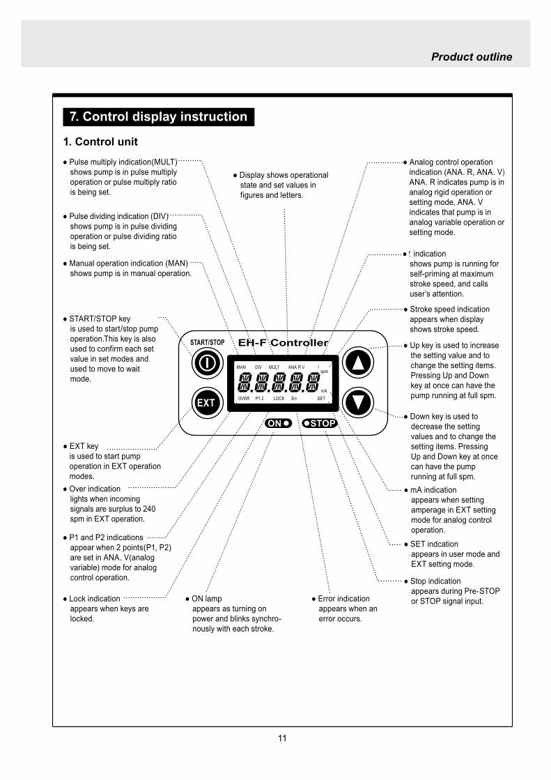
11
Product outline
7 Control display instruction
1 Control unit
ON STOP
EXT
EH-F ControllerSTARTSTOP
DIVMAN
OVER P1 2 LOCK Err SETmA
spmMULT ANAR V
Manual operation indication (MAN)shows pump is in manual operation
indicationshows pump is running for self-priming at maximum stroke speed and calls userrsquos attention
mA indicationappears when setting amperage in EXT setting mode for analog control operation
SET indcationappears in user mode and EXT setting mode
Stop indicationappears during Pre-STOP or STOP signal input
Stroke speed indication appears when displayshows stroke speed
Pulse dividing indication (DIV)shows pump is in pulse dividing operation or pulse dividing ratio is being set
Pulse multiply indication(MULT) shows pump is in pulse multiply operation or pulse multiply ratio is being set
Display shows operational state and set values in figures and letters
STARTSTOP keyis used to startstop pump operationThis key is also used to confirm each set value in set modes and used to move to wait mode
EXT keyis used to start pump operation in EXT operation modes
Over indicationlights when incoming signals are surplus to 240 spm in EXT operation
P1 and P2 indicationsappear when 2 points(P1 P2) are set in ANA V(analog variable) mode for analog control operation
Lock indicationappears when keys are locked
ON lampappears as turning on power and blinks synchro-nously with each stroke
Error indicationappears when an error occurs
Analog control operation indication (ANA R ANA V)ANA R indicates pump is in analog rigid operation or setting mode ANA V indicates that pump is in analog variable operation or setting mode
Down key is used to decrease the setting values and to change the setting items Pressing Up and Down key at once can have the pump running at full spm
Up key is used to increase the setting value and to change the setting items Pressing Up and Down key at once can have the pump running at full spm
12
Product outline
2 Typical indications
3 Warning indications
Indications Show
Pump is operating in the manual operation modeThe display shows the set spm
Pump is operating in the analog control mode(ANAV) of the EXT operation Display indicates 168 spm
The stroke speed is being set while pump is operating in the multiply operation(MULT)
Pump is being stopped via STOP input while operating in the dividing operation(DIV)
MAN spm
LOCK SET mA
MAN ANA V spm
MULT
SET
DIV spm
Indications shows
Key lockAll the key operation can be ineffective in order to prevent any per-son other than user from operating the pump This function can be active by pressing STARTSTOP key for 5 seconds in any pump states and LOCK indication appears Key lock function can be released by pressing STARTSTOP key for 5 seconds when LOCK indication appears on the display
The left indication appears when input signal is below 4 mA with the 4-20 or 20-4 pattern in ANA R (Analog rigid) mode In this state pump is under suspensionBy pushing STARTSTOP key once this error is released and the mode moves to waiting mode Check wiring and signals
OVER indication appears when incoming signals are surplus to 240 spm in EXT operation
MAN spm
LOCK SET mA
ANAR
Err
spm
MAN spm
OVER
13
Installation
1 Before installation
Working without disconnecting the power supply may cause an electrical shock Before engaging upon any working procedures involving the pump be sure to turn the power supply switches off to stop the pump and the related devices
Upon becoming aware of a dangerous sign or an abnormal condition while engaging on the installation terminate the work immediately and start it from the beginning again
Do not operate the pump on the voltage which is not specified on the nameplate Failure to do so may result in damage or a fire Be sure to earth the pump
Do not place any dangerous materials or flammable objects near the pump for the sake of safety
WARNING
CAUT ION
1 Dropping the pump or subjecting it to a strong impact may result in the faulty performance Handle the pump with care Do not use the damaged pump for the prevention of the electri-cal leak or shock
2 When installing pump avoid the places where the pump is exposed to the direct sunlight the ambient temperature is above 40 digC or the relative humidity is above 85 Though the pump has a simple waterproof and dust-proof structure it is recommended to protect the pump with a cover when installing it outdoor
3
Installation
14
3 Select a level floor and use the four M6 bolts to firmly anchor the pump so as not to allow any vibration If the pump is inclined the discharge amount may decrease considerably
4 Pump should be installed in a well-ventilated place in summer and free from freezing in win-ter
6 Place the pump as close to the suction tank as possible realizing a flooded suction system (It is recommended the pump should be located lower than the suction-side tank)
7 If the pump is used to feed some liquid that gen-erates air bubbles easily (sodium hypochlorite hydrazine solution etc) the system must be positioned in a cool dark place away from direct sunlight If a tank is installed realize a flooded suction system
5 Select the installation site convenient for the future maintenance and inspection
2 Precaution for piping Piping vibrates due to the pulsation from pump Piping should be supported in order to prevent the vibra-
tion Install an air chamber or an accumulator to reduce the pulsation Ask us for further information Be careful not to have hose bend when arranging tubing It is recommended to arrange the short piping as much as possible The longer piping length the more
pressure drops and can exceed the allowable pressure of pump and can cause the over feed phenom-enon
It is recommended an automatic air bleed valve or a pressure relief valve should be installed in order to release the pressure of discharge piping for maintenance
It is recommended to install a relief valve on the discharge side piping that releases pressure automati-cally
Install a pressure gauge on the discharge side piping in order to measure the pressure inside the piping When installing EH-F pump with the flange connections or the union connections be sure to have the
connections on the discharge side fixation on wall pillar or the frame of equipment for the prevention of vibration Make sure that the piping is fixed as well
CAUTIONIncomplete fixation of pump and piping can lead to the damage to these products Significant vibration often results from the incomplete support for the discharge side connection of pump In case the direct support for the flange or union connection can not be secured try to support pump close to the discharge connection as much as possible
15
Installation
Check valve
Air bleedValve
Discharge hose
Pump
Tree way joint
Accumulator
Drain valve
Discharge valve
Back pressure valve
Pump
Suctionvalve
Air bleed valve
Airchamber
Pressure gauge
Relief valve
3 Piping1 Recommended piping drawings
Arrange piping to meet the suction and dis-charge requirement Especially pay attention to piping arrangement in case of handling the slurry which has settling property
Installation
16
Hose
Hose stopper
Fitting spacer
O ring
Fitting nut
Place hose stoppers with R surfaceface to face with fitting spacer
Hose
Hose stopperFitting spacer
O ring
Fitting nut
Fitting
Suction port
Pump head
2 Piping arrangement1 For hose connection first fit a fitting nut and then a
hose stopper and a fitting spacer in the last place If the hose stopper is not fitted properly leakage may occur and suction amount may decrease
The hose end should be secured by a hose stop-per Insert a hose end into a fitting spacer via a fitting nut and a hose stopper Then squash the hose end between the hose stopper and the fit-ting spacer Finally screw the fitting nut in
The hose stopper should be placed with its R surface face to face with the fitting spacer An incomplete hose stopper fixation or a reverse hose stopper placement can lead to leakage or insufficient suction
CAUTIONReverse hose stopper placement can dam-age hose
Fitting nut is made of plastics The fitting nut may break when it is tightened excessively
If attached hose is not long enough prepare a substitute hose such as chloroethene braided hose and polyethylene hose with a suitable bore to the hose fitting spacer
CAUTIONIt is very dangerous to attach the different size hose It may come off
Insert the fitting spacer into hose as deep as possible If the insertion is not enough hose may come off and leakage may result
Be careful not to lose the attached O rings Leakage or suction failure may result without an O ring
2 Hose connection tends to loose if liquid or ambient atmosphere is higher than normal temperature Re-tighten the fitting nut properly after starting opera-tion Be careful not to tighten the nuts too much
3 When fitting the hose again after detaching it for maintenance cut the end of hose off about 10 mm and insert it
17
Installation
4 Check valveEH-F35 45 (VCV6PC) types are attached with a check valve Fit the check valve to piping in the fol-lowing cases
1 The suction side liquid level is higher than the dis-charge side liquid level (Fig A) When injection point is below the liquid level of suction side at atmospheric pressure
2 The suction side pressure is higher than the discharge side pressure (Fig B)
3 The discharge side liquid level is higher than the suction side liquid level but the differential height between both liquid level is 5 m or below (Fig C)
4 The loading pressure of piping resistance and dis-charge head to the pump is under 013 MPa
Suction side Discharge side
Figure A
Figure B
5m
Figure C
To chemical tankor vessel
Remove check valve
3 Piping for bleedingPrior to bleeding disconnect hose and point a hose end at a suction tank or vessel Remove a check valve if it is attached on the discharge side piping
18
Installation
R12
Oslash12
5 Check valve mounting1 Tap the female thread of NPT12 at an injection
point Check valve is provided with the male thread of R12 Cut off the unused portion to fit it on a pip-ing
2 Apply seal tape on the threaded portion of the check valve and screw it in the injection point Pinch the check valve body lightly with a spanner and tighten it for easy mounting
3 When fitting a hose into a check valve with the check valve on main pipe tighten the fitting nut holding the check valve body by hand
4 Cut the end of check valve(empty 12) accordingly when mounting it in a small pipe It is recommended the end of the check valve comes at the centre of pipe bore
It is recommended to mount a check valve via a valve for maintenance Provide NPT12 female thread and screw it in Valve should be resistant to the chemical liquid in use
Valve
Check valve
Check valve body
Apply seal tape
Fitting nut
Pipe
Cut the end nozzle offif it is too long compared topipe bore
6 Flange connection and union connection1 Flange units and union sockets are packed apart from pump body Fit the flange units or the union sockets to
pump body before use Refer to the following figures2 Secure the sealing by fitting O rings to each connection
CAUTIONWhen mounting flange units or union sockets to pump body be careful not to allow O ring to get out of the groove Especially pay attention to the O ring on the groove on suction side
3 Fix the flange units or the union sockets to the pump body by tightening fitting nuts In this case first tighten the fitting nuts by the hand and then re-tighten it by 90 degrees with a spanner
CAUTION
Fitting nut is made of plastics The fitting nut may break when tightened excessively
Flange connection type
19
Instillation
Flange
Flange
Fitting nut
O ring
O ring
Elbow
Pump body
Fitting nut
Drain
Discharge
Air chamber
7 Accumulator and air chamber mountingInstall an accumulator or an air chamber on piping for the prevention of the vibration from the pulsation of pump discharge hose
20
Installation
8 Piping (General notes)1 Keep piping short and less bends Do not make the projections where air can remains
2 Support piping to avoid having the pump subject to the piping weight especially when wet-end mate-rial is made of PVC
3 In case of transferring the slurry which tends to settle do not make U shape on piping A drain plug is required at the lowest portion of piping as well
4 In case of transferring the viscous or toxic liquid or the liquid which tends to settle provide the piping for cleaning for the purpose of maintenance
5 In case of transferring the high temperature or low temperature liquid the telescopic motion of piping from temperature variation should be taken into consideration
6 Select pipe materials based on a through examination of the corrosive resistance and the estimated pressure applied to piping
7 Do not allow any adhesive agent to get in pump when connecting PVC-made pipe on the discharge side piping
8 Clean the inside of piping before installing pump in it
9 A relief valve is required to protect pump and piping Install a relief valve on the discharge piping near the pump
9 Suction piping1 Regarding suction piping a flooded suction system should be realized The bore of suction piping is
recommended to be larger than that of pump suction port
2 Each joint of suction piping needs to be mounted carefully in order to prevent air from coming in Air influx into piping may cause discharge performance failure and instability
10 Discharge piping1 Mount a relief valve on the discharge piping near pump A discharge valve should be mounted beyond
the relief valve
2 The pressure resistance of discharge piping should be higher than the set pressure of relief valve Mount each joint carefully
21
Installation
4 Electrical wiring
1 Power cord connection
Electrical works and the handling of power source must be done by qualified person
Do not operate pump with the wet hand
Make sure that power is not turned on while working on wirng
Do not dismantle electronic circuit
Electronic circuit may be broken Never apply other voltages than a rated voltage
WARNING
CAUT ION
High power equipment
CAUTION Avoid sharing a power source with a high
power equipment This can lead to the fail-ure of the electronic circuit of control unit due to extremely large surge voltage
The noise from an inverter can cause fail-ure
22
Installation
P
Surge absorption element
PNoise cut transformer
CAUTION
2 Wiring procedure
Electronic circuit of control unit may be failed by extremely large surge voltage Do not use the pump near to the high power equipment of 200V or more which may generate large surge voltage If the use of high power equipment is inevitable take either of the following measuresa Install a surge absorption element such
as varister with 2000A or more durability on the power point
b Install a noise cut transformer
CAUTION
Only qualified operatorsservice staff should be in charge of the related electrical arrange-ment and control of the power source Failure to observe this instruction may result in injury to person or damage to assets
Never connect wires while power is turned on otherwise an electrical shock or a short-circuit of controller may result Be sure to turn off power before wiring
Internal circuit is still electrified right after turning off power Take 1 minute or more to start wiring
Do not band a power cable either electrical wires or relay output wires
Earthing wire is equipped with a jumper pin Keep the jumper pin equipped in use
Do not combine the EXT or STOP signal line with a power cord or a power cable Do not com-bine power source line with the EXT or STOP signal line by a concentric cable (5 wires cable or so) Otherwise noise come about through EXT and STOP wires due to the induction effect from power cable and it may results in wrong operation or the failure of pump
Regarding frequent ON-OFF operation it is recommended to stop pump thorough STOP input terminal but not by connecting or disconnecting power source When connecting and discon-necting power cord can not be avoided it should be within 6 times an hour
23
Installation
Procedure to connect the signal cordUse DIN connector of five poles and four polesThe following connectors made by Binder in Germany are recommendedAsk IWAKI for the detail of Binder connector 5 poles 713 series 99-0436-10-05 for input signal 4 poles 715 series 99-0430-15-04 for level sensor
The following connector made by Hirschmann in Germany is recommendedAsk IWAKI for the detail of Hirschmann connector 4 poles GDS307 for output
The following procedures are based on the connector made by Binder and HirschmannIf a similar connector is used the wiring should be made according to the instruction manual of the manufacturer of connector
In case of Binder connector(1) Dismantle the connector and pass the wire through it Outer diameter of the cable should be oslash4-6
Using the different cable in diameter the connector can not be sealed properly
(2) Strip the cable ends and insert wire to the appropriate positions and connect them with screwsThe maximum allowable cross section of the wire is 075mm2
(3) After connecting the wire assemble the connector securely Slightly pull the cord to confirm that the cord connection is secured Perfect sealing can not be obtained unless the cord connection is loose
24
Installation
In case of Hirschmann connector(1) Dismantle the connector and pass the wire through it Insert a minus screw driver into the place shown by
ldquoLIFTrdquo and lift it up Outer diameter of the cable should be 35-6 mm Using the different cable in diam-eter the connector can not be sealed properly
(2) Strip the cable ends and insert wire to the appropriate positions and tighten them with screwsThe maximum allowable cross section of the wire is 075mm2
(3) After connecting wire assemble the connector securely Slightly pull the cord to confirm that the cord connection is secured Perfect sealing can not be obtained unless the cord connection is loose
Terminal position
NA Not Applicable
Connection of level sensorThe controller corresponds to two stage level sensor Connect the pre-alarm signal to Pre-STOP and the alarm signal to STOP When the pre-alarm signal comes in the orange lamp lights but the pump does not stop When a contact type is used connect wires to STOP and COM2 For open collector output level sensor Pay attention to the polarity Pre-Stop and STOP are plus (+) and COM2 is minus (-) (Max charged voltage 5V Current 18mA) For contact output level sensor Use the one designed for electronic circuit and the minimum applicable load of 1mA or less
Connection inside connector 1 STOP 2 Pre-STOP 3 Free 4 COM2
1
2
3
4 CLOSE
ON
PUMP
Level Sensor(STOP)
OPEN
Pulse
COM
+12VDC
NA
ANA(4-20)
Pre-STOP
STOP
COM
NA
OUT
25
Installation
Stop functionStop function is the function to stop the pump by the external signal Connect the wires to STOP and COM2 in the same way as the level sensor connection
CAUTION
Frequent stop and start of pump should be done by using STOP function (ON and OFF of STOP terminal) If you can not use STOP function and are forced to operate pump by turning OFF and ON of power source ON and OFF of power source should be limited to six times an hour
Pulse signal inputPulse signal input is used when the pump runs in the DIV or MULT of EXT modeDIV means dividing and MULT means multiply In case of open collector signal Pay attention to the polarity Pulse is plus (+) and COM1 is minus (-) (Max charged voltage 5V Current 18mA) In case of contact signal Use the one designed for electronic circuit and the minimum applicable load of 1mA or less
Connection inside connector 1 Free 2 Pulse 3 Free 4 12VDC 5 COM
3
2
4
15
Analog signal inputAnalog signal input is used when the pump runs in ANAR or ANAV of EXT modeANAR means analog rigid and ANAV means analog variable
Connection inside connector 1 ANA 2 Free 3 Free 4 Free 5 COM
3
2
4
15
26
Installation
Output signalOUT Photo MOS relay outputStandard is output synchronous with stroke Output is activated synchronous with each pump stroke
Connection inside connector 1 OUT 4 OUT
OUT 1
2
34
Surge voltage The electronic circuit of the control unit may be affected by excessively high surge voltage Do not operate the pump near the high-power elec-trical equipment of 200V or above that generates high surge voltage Under unavoidable circumstances take either of the following measures(1) Use a surge absorbing element (such as a
varistor with the surge resistance of 2000A or more) at the pump power supply connection
(2) Use a noise-cut transformer
Surge absorbing element
Noise-cut transformer
1 Preparation for pump operationBefore pump operation check that
bull Liquid tank is filled enough Supply liquid if it is less than the required levelbull There is no liquid leakage or congestion due to breakagebull Both suction and discharge side valves are openedbull Pump is connected to the predetermined power source correctlybull Electrical wiring is correct and there is no possibility of a short circuit or current leakage
2 BleedingBleeding is a process to eliminate the air inside the suction-side piping Be sure to carry out an air elimi-nation prior to initiating the pump operation after replacing the liquid inside a tank and after a long peri-od of storage Air gushes together with chemical liquid when carrying our bleeding For safety reasons first turn the end of a bleeding hose to a tank or a container
CAUTION
Some liquids may cause skin trouble or affect the quality of mechanical parts Wipe off chemi-cal liquid immediately when they splash on the hand or mechanical parts
27
Operation
1 Pump Operation
WA R N I N G Wear protective clothing
Wear protective clothing such as a protective mask safety gloves or so when handling chemical liquid
Do not operate pump with a discharge-side valve completely closed Operating the pump with the discharge-side valves fully closed may cause the liquid spillage or
the extremely high pressure inside the pump or the discharge-side pipingtubing This could lead to a piping burst Be sure not to operate pump with the discharge-sides valve closed
CAU T I O N A long time dry running (longer than 30 minutes) may cause the pump overheat and it could lead
to the deformation of the pump unit consists of a pump head and valve cases or so or may loosen the pump head fitting and result in liquid leakage
If the hex socket cap bolts on a pump head are loosened liquid leakage may resultBe sure to fasten all the 6 or 8 hex socket cap bolts tightly before starting the initial pump opera-tion And periodically check the looseness of the bolts on the pump head and retight the bolts as necessary
bull Tightening torque255NbullmTighten all the bolts diagonally applying equal tightness
If electric wiring gets wet due to accidental liquid spillage fire or electrical shock may occur Never get it wet When the electric wiring gets wet turn off power and wipe the liquid away
A frequent ON-OFF operation should be conducted by using STOP function(ON - OFF signals to STOP terminal) In case the STOP function is not available for the ON-OFF operation the ON - OFF operation by turning onoff power should be limited to six times an hour
4
28
3 Procedure for bleeding
Check valve should be removed
To tank or drain pan
100
75
50
25
0 25 50 75 100
(Fixed stroke length)
Stroke length adjustment
240spm
180spm
120spm
Flow
rate
Operation
[1] Extend the tube connected to the discharge-side fitting nut of pump to a chemical tank or a drain pan Then start pump operationbull Remove a check valve if it is installed on dis-
charge-side
[2] Operate the pump for about 10 minutes to eliminate air completely
[3] When the air in pump head is completely eliminated and liquid is replaced return the discharge-side tube to the regular tubing position
[4] Finally make sure there is no leakage in any section
4 Discharge capacity adjustmentDischarge capacity can be adjusted by both the stroke length adjustment and the stroke rate adjust-ment but basically adjust it via the stroke rate adjustment Stroke length adjustment is an auxiliary way to cover the range where the stroke rate adjustment can not reachPay attention to the following for correct procedure
Stroke rate adjustment(1) For some liquids which diffuses gas such as sodium hypochlorite and hydrazine solution adjust discharge capac-
ity by means of the stroke rate adjustment with the stroke length about 100 Gas lock may occur if the stroke length is set to short
(2) When the back pressure on discharge side is high adjust discharge capacity by the stroke rate adjustment with the stroke length about 100
(3) In case reaction is greatly influenced depending on the discharge capacity per pump shot in the application of neutralization or titration adjust discharge capacity by the stroke rate adjustment with the shortened stroke length and reduce the discharge capacity per shot
1 Discharge capacity adjustment procedureAppropriate stroke length and stroke rate are decided on the pump operating condition and liquid characteristics Following ways are recommended for proper calibration
(1) Set stroke length at 100 and roughly adjust discharge capacity by adjusting stroke rate
(2) Measure discharge capacity(3) If the measured capacity is below the wanted value
increase the stroke rate and measure again the dis-charge capacity
(4) Adjust stroke length for the fine adjustment of discharge capacity(5) Determine a discharge capacity at the last and confirm the wanted capacity is discharged
CAUTION
29
100
75
50
25
0 60 120 180 240spm
Fixed stroke length
Stroke rate adjustment
Flow
rate
Screw driverOPEN
LOCK
100
75
50
25
0 25 50 75 100
Fixed stroke rate
Flow
rate
Stroke length adjustment
Operation
2 Stroke rate adjustmentStroke rate is adjusted by the key operations of control unit Control the plunger stroke rate per minute from 1 to 240 spm via control unit
3 Stroke length adjustmentStroke length adjustment knob is locked with a screw Loosen the screw before adjustment and lock it afterwards
(1) Turn on pump and adjust the discharge capacity by turning the stroke length adjusting knob while pump is running
(2) The left graph shows the relation between stroke length and discharge capacity The maximum dis-charge capacity is shown on the name plate
bull The usage between 40 and 100 is practi-cal
Do not turn the stroke length adjusting knob when pump stops
CAUTIONBe sure to tighten the screw on the adjust-ment knob after an adjustment The knob may rotate unintentionally due to a loose fixation This may result in the fluctuation in a discharge rate
30
Mode ParameterDefault value
Setting range Step
Manual operation Stroke speed 240 1-240DIV setting Dividing ratio frasl 1 1-9999
MULT setting Multiply ratio times1 times1-9999ANA R setting 4-20 4-20 20-4 0-20 20-0
ANA V setting
P1 amperage 40 00-200P1 stroke speed 0 0-240P2 amperage 200 00-200P2 stroke speed 240 0-240
User setting
EXT operation ANA V DIV MULT ANA R ANA V
Anti-chatteringMECH MECH ELECST05 ST05 ST20 ST50FT01 FT02 FT04
Buffer memory MEM-N MEM-N MEM-Y
111-
011
011
2 Control unit operationEH-F type pump is controlled by means of setting or changing the setting values of the controller Control functions are various at each operation mode Read this section carefully before operation
Default parameter values
5 Full operationPut pump in use after bleeding and adjusting discharge capacityPump runs in manual operation or in accordance with the setting of control unit
6 Manual operationStarting pump After turning on power ON lamp (Green) appears and display shows WAIT mode For
the first time to turn on power MAN lamp appears and pump starts after pushing STARTSTOP key once
Stop pump Push STARTSTOP key to turn off MAN lamp and stop pump Pump starts and stops every time STARTSTOP key is pressed
7 EXT operationRefer to the next section of 2 Control unit operation
8 Shout down When pump will not in use for a long time (one month or more)
Run pump with clean water about 30 minutes in order to clean the wet-end parts and the inside of pip-ing before storage
When re-starting pump after a long time storage If pump dose not suck up liquid clean valve sets and remove the sticking foreign matters Carry out an air elimination and adjust discharge capacity when air stays inside pump head Refer to page 28 3 Procedure for bleeding
Operation
---
-
31
AN
A V
(Ana
log
var
iabl
e)
DIV
(Pul
se d
ivid
ing)
MU
LT(P
ulse
mul
tiply
)A
NA
R(A
nalo
g ri
gid)
SE
TS
ET
Use
r mod
e
EX
T m
ode
sele
ctio
n
EX
T
EX
TE
XT
EX
TE
XT
EX
T EX
T
EX
T
EX
T
EX
T
EX
T
EX
T
EX
T
EX
T
EX
T
EX
T
EX
T
EX
T
3 sec
onds
or m
ore
Wai
t mod
e
Set
ting
of fi
xatio
n pa
ttern
EX
T m
ode
Man
ual o
pera
tion
Set
ting
of s
troke
num
ber
AN
A R
(Ana
log
rigi
d)M
ULT
(Pul
se m
ultip
ly)
DIV
(Pul
se
div
idin
g)
AN
A V
(Ana
log
var
iabl
e)
anti-
chat
terin
gse
tting
dis
play
Setti
ng o
f div
idin
g ra
tioS
ettin
g of
cou
nt n
umbe
r
Curre
nt va
lue of
P1
Stro
ke nu
mbe
r of P
1
Curre
nt va
lue
of P
2
Stro
ke nu
mbe
r of P
2
EX
T O
pera
tion
Dis
play
EX
T se
tting
mod
e
Buf
fer m
emor
yse
tting
dis
play
Pow
er O
N
spm
MA
Nsp
m
spm
DIV
DIV
SE
TS
ET
MU
LT
MU
LTsp
mA
NA
V
spm
AN
AR
AN
AR
SE
Tm
AS
ET
mA
spm
AN
A
V
P1
mA
SE
T
spm
AN
A
V
P1
AN
AR
SE
Tm
A
AN
AR
SE
Tm
AS
ET
AN
A
V
P 2
SE
T
spm
AN
A
V
P 2
AN
AR
SE
Tm
A
AN
A
V
SE
TS
ET
SE
T
SE
T
SE
T
SE
T
SE
T
SE
T
SE
T
SE
T
SE
TS
ET
1 Overview Operating Scheme
Operation
1 means automatic transfer WAIT mode is selected when the power is switched on for the first time On and after the initial power activation pump restores the previous status right before the power is switched off
2 Regarding MANUAL mode pump starts operation by pushing STARTSTOP key at WAIT modePushing STARTSTOP key again the pump stops and returns to WAIT mode
3 Regarding EXT operation pushing EXT key at WAIT mode the pump moves to EXT mode and starts operationPushing STARTSTOP key stops the operation and returns the pump to WAIT mode
4 The change of each setting of EXT operation is accessible by pushing EXT key at EXT mode Pushing EXT key after the setting pump starts in EXT operation according to the changed setting
5 Pushing EXT key for 3 seconds at WAIT mode pump moves to USER mode At USER mode the EXT mode selection and the detailed setting such as the setting of buffer memory or so can be obtained
For details refer to each section of 2 Pump operation
2 Pump operation1 Operation of controller
Before turning on power confirm the specified power source on the nameplate
CAUTION
Connecting any other powers than the one shown on nameplate to pump is strictly prohibitedIt could lead to pump trouble or failure
Operation
32
1 Turning on powerDisplay shows WAIT mode when pump is turned on for the first time After the initial power activation the pump restores the previous mode right before the power was turned off last time If power is turned off at any setting modes WAIT mode appears at the next power activation
Stroke speed setting value is shown on display at WAIT mode ON lamp lights (Green)
EXT
EH-F ControllerSTARTSTOP
ON STOP
spm
33
2 Manual operation(1) Stroke speed can be adjusted by and
keys The figure changes quickly when either or key is depressed The picture below
shows the stroke speed is set to 160 spm
EXT
EH-F ControllerSTARTSTOP
ON STOP
spm
EXT
EH-F ControllerSTARTSTOP
ON STOP
MAN spm
EXT
EH-F ControllerSTARTSTOP
ON STOP
spm
(2) Push STARTSTOP key once to start the pump operation MAN indication appears and ON lamp blinks synchronously with each stroke
(3) MAN indication disappears and ON lamp stops blinking as STARTSTOP key is pushed again Pump enters WAIT mode
Operation
Operation
34
EXT
EH-F ControllerSTARTSTOP
ON STOP
ANA V
P1 SET mA
EXT
EH-F ControllerSTARTSTOP
ON STOP
P1 SET
ANA V spm
EXT
EH-F ControllerSTARTSTOP
ON STOP
spm
EXT
EH-F ControllerSTARTSTOP
ON STOP
ANA V spm
(4) Set the current value at P1 Figure increases or decreases as or key is pushed The pic-ture below shows 80 mA is set to point 1
EXT
EH-F ControllerSTARTSTOP
ON STOP
ANA V
P1 SET mA
(5) Pushing EXT key once spm appears on the display while mA disappears The picture below shows the number of strokes at P1
EXT
EH-F ControllerSTARTSTOP
ON STOP
P1 SET
ANA V spm
3 EXT operation (ANA V mode)(1) Push STARTSTOP key to move to WAIT mode
if pump is in another mode Go to next step if pump is in WAIT mode
(2) ANAV indication appears and pump enters an EXT mode as EXT key is pushed once Pump starts operation in accordance with current sig-nals and various settings ON lamp blinks at each pumping during operation Pump is con-trolled via the EXT mode which was select-ed at USER mode The initial setting of EXT mode is ANA V mode Select a preferable EXT mode in USER mode The picture below shows ANA V mode (The spm on the display changes according to input signals)
(3) Push EXT key once when pump is running in ANA V mode Display indicates the setting display of ANA V mode spm indication dis-appears and P1 SET and mA indications appear on the screen
(6) Set the number of strokes at P1 Figure increasesdecreases as key is pushed Picture below shows 10 spm is set for point 1
Operation
35
(7) Push EXT key to move to the setting display of the current value at P2 P1 and spm disap-pear and P2 and mA appears instead
EXT
EH-F ControllerSTARTSTOP
ON STOP
ANA V
P 2 SET mA
EXT
EH-F ControllerSTARTSTOP
ON STOP
ANA V
P 2 SET mA
EXT
EH-F ControllerSTARTSTOP
ON STOP
P 2 SET
ANA V spm
(11) Push EXT key to return to EXT mode Pump starts to run in ANA V mode on the setting of (4) through (10) ON lamp starts to blink at each pumping
EXT
EH-F ControllerSTARTSTOP
STOPON
ANA V spm
EXT
EH-F ControllerSTARTSTOP
ON STOP
P 2 SET
ANA V spm
EXT
EH-F ControllerSTARTSTOP
ON STOP
spm
(8) Set the current value of P2 by pushing and keys Picture below shows 180 mA is set to
point2
(9) Pushing EXT key once spm appears on the display while mA disappears The picture below shows the number of strokes at P2
(10) Set the number of strokes at P2 by pushing and keys Picture below shows 200
spm is set to point 2
(12) Pushing STARTSTOP key pump enters WAIT mode and pump stops ON lamp stops blink-ing and ANAV indication disappears
CAUTIONWhen the setting of the buffer memory is OFF keep the number of strokes in the dividing operation 240 spm or below The input signals to operate the pump over 240 spm can cause an unstable pump operationWhen the setting of the buffer memory is ON the pump operates for all the input pulse signalsPump keeps operating after all the signals are stopped in this case Be careful when setting of buffer memory
Operation
36
EXT
EH-F ControllerSTARTSTOP
ON STOP
DIV
SET
EXT
EH-F ControllerSTARTSTOP
ON STOP
DIV
SET
EXT
EH-F ControllerSTARTSTOP
STOPON
DIV spm
EXT
EH-F ControllerSTARTSTOP
ON STOP
spm
(2) Pushing EXT key DIV appears and pump starts operation in the ratio of input pulse sig-nals a pumping ON lamp blinks synchronous-ly at each pumping The initial setting of EXT selection is ANA V mode Change mode to DIV mode via USER mode Refer to P 40 for detail information
(3) Push EXT key while pump is operating in DIV mode Pump stop running and SET indication appears on the DIV setting display in stead of spm indication
(4) Enter a dividing ratioFigure increasesdecreases when key is pushed The picture below shows 10 is set
4 EXT operation (DIV mode)
(1) Push STARTSTOP key to move to WAIT mode if pump is in another mode Go to next step if pump is in WAIT mode
CAUTIONOn condition the setting of buffer memory is OFF do not input any pulse signals during the pumping motions for a input pulse signal in the multiply operation These input pulse signals are cancelledWhen the setting of buffer memory is ON pump operates for all the input pulse signals
Operation
37
EXT
EH-F ControllerSTARTSTOP
ON STOP
spm
EXT
EH-F ControllerSTARTSTOP
STOPON
DIV spm
EXT
EH-F ControllerSTARTSTOP
ON STOP
spm
EXT
EH-F ControllerSTARTSTOP
ON STOP
MULT
(5) Push EXT key to return to EXT operating mode Pump starts to run on the setting at item (4) ON lamp blinks synchronously at each pumping
(6) Pushing STARTSTOP key pump enters WAIT mode and pump stopsDIV indication disappears and ON lamp stops blinking
5 EXT operation (MULT mode)
(2) MULT indication appears and pump starts running in an EXT operation mode in the ratio of an input pulse signal pumpings as press-ing EXT key ON lamp blinks at each pump-ing Display shows the rest of the number of strokes In MULT mode the number of strokes is equal to the setting value in manual opera-tionThe initial setting of the EXT mode selection is ANA V mode which is the operation in pro-portion to current First select MULT mode via USER mode Refer to P 40 for detail informa-tion
(1) Push STARTSTOP key to move to WAIT mode if pump is in another mode Go to next step if pump is in WAIT mode
Operation
38
EXT
EH-F ControllerSTARTSTOP
ON STOP
spmEXT
EH-F ControllerSTARTSTOP
ON STOP
ANAR spm
EXT
EH-F ControllerSTARTSTOP
ON STOP
MULT
SET
EXT
EH-F ControllerSTARTSTOP
ON STOP
MULT
EXT
EH-F ControllerSTARTSTOP
ON STOP
spm
EXT
EH-F ControllerSTARTSTOP
ON STOP
MULT
SET
(5) Push EXT key to return to MULT mode(3) Pushing EXT key when pump is running in the multiply operation calls the setting display of MULT mode and SET indication appearsPump stops running and ON lamp stop blinking
(4) Enter the number of pumpings per input signalFigure increasesdecreases when key is pushed The picture below shows the pump-ing number is set to 1800 times per an input signal
6 EXT operation (ANA R mode)(1) Push STARTSTOP key to move to WAIT mode
if it is in another mode Go to next step if it is in WAIT mode
(6) Pushing STARTSTOP key recalls WAIT mode and pump stops spm indication appears in stead of MULT indication
(2) Pushing EXT key ANAR appears and pump starts running in the ratio of an input pulse sig-nal pumpings ON lamp blinks at each pump-ing The initial setting of the EXT mode selec-tion is ANA V mode which is the operation in proportion to current is selected First select ANA R mode in USER mode Refer to P 40 for more information
Operation
39
EXT
EH-F ControllerSTARTSTOP
ON STOP
ANAR
SET mA
EXT
EH-F ControllerSTARTSTOP
ON STOP
ANAR spm
EXT
EH-F ControllerSTARTSTOP
ON STOP
ANAR
SET mA
EXT
EH-F ControllerSTARTSTOP
ON STOP
spm
(4) Figure increasesdecreases when key is pushed The picture below is when it is set to 0-240 spm for 20-4 mA
(5) Push EXT key to return to EXT mode Pump starts to run on the setting at item (4) ON lamp blinks synchronously at each pumping
(6) When pushing STARTSTOP key pump enters WAIT mode and stops running ON lamp stops blinking and ANAR disappears
(3) Pushing EXT key when pump is running in the multiply operation calls the setting display of ANAR mode and SET and mA indications appear while spm disappears Pump stops running and ON lamp stops blinking
Operation
40
EXT
EH-F ControllerSTARTSTOP
ON STOP
ANA V
(5) Push EXT key to confirm the desired EXT mode Pump displays the EXT mode selection The picture below shows DIV appears to indi-cate DIV mode is selected
EXT
EH-F ControllerSTARTSTOP
ON STOP
DIV
EXT
EH-F ControllerSTARTSTOP
ON STOP
SET
EXT
EH-F ControllerSTARTSTOP
ON STOP
spm
EXT
EH-F ControllerSTARTSTOP
ON STOP
spm
EXT
EH-F ControllerSTARTSTOP
ON STOP
SET
7 USER settingThe setting of each function is changed in USER mode Have the pump entering WAIT mode in order to move to USER mode OUT (Output) is synchronous with spm and it can not be changed
7-1 EXT mode selection Any one of DIV (pulse dividing) MULT (pulse multiply) ANAR (analog rigid) or ANAV (analog vari-able) can be active in EXT mode The initial mode when shipped from factory is ANAV
(1) Push STARTSTOP key to move to WAIT mode if it is in another mode If it is in WAIT mode go to next step
(2) Press EXT key for more than 3 seconds to move to USER mode The picture below shows pump enters the EXT mode selection
(3) Pushing EXT key SET appears and display shows the mode currently set Picture below shows ANA V mode is selected
(4) Push or key to select a desired EXT mode The picture below shows DIV mode is selected
(6) Push STARTSTOP key to move to WAIT mode spm appears while DIV goes out
Operation
41
EXT
EH-F ControllerSTARTSTOP
ON STOP
spm
EXT
EH-F ControllerSTARTSTOP
ON STOP
ANA V
EXT
EH-F ControllerSTARTSTOP
ON STOP
SET
(3) Push key once
EXT
EH-F ControllerSTARTSTOP
ON STOP
(4) Push key again to move to the anti-chatter-ing setting display
EXT
EH-F ControllerSTARTSTOP
ON STOP
(5) Pushing EXT key display shows the mode cur-rently set and SET appears on it The picture below shows when MECH is selected
EXT
EH-F ControllerSTARTSTOP
ON STOP
SET
7-2 Setting of anti-chattering Anti-chattering function is settable against the incoming pulses during the DIV or MULT operation For the long chattering of mechanical contact such as relay set a large figure via MECH For the high speed (high frequency) chattering of the semi-conductor type contact such as transistor set a small figure via ELEC ST05 of MECH is initial setting
(6) Select MECH by or key for a mechani-cal contact And select ELEC for a semi-conductor contact The picture below shows ELEC is selected
(1) Push STARTSTOP key to move to WAIT mode if it is in another mode If it is in WAIT mode go to next step
(2) Press EXT key for more than 3 seconds to move to USER mode The picture below shows pump enters the EXT mode selection
Operation
42
EXT
EH-F ControllerSTARTSTOP
ON STOP
SET
(7) Push EXT key to display the current set state The picture below shows FT01 is selected
EXT
EH-F ControllerSTARTSTOP
ON STOP
SET EXT
EH-F ControllerSTARTSTOP
ON STOP
EXT
EH-F ControllerSTARTSTOP
ON STOP
spm
7-3 Setting of buffer memoryIn case pump operation can not catch up with the input pulse signals in DIV or MULT operation exces-sive pulse signals can be put in memory up to 65535 pulses However the excessive pulses can not be restored if once power is off or mode is changed
EXT
EH-F ControllerSTARTSTOP
ON STOP
spm
(2) Press EXT key for 3 seconds or more to move to USER mode The picture below shows the EXT mode selection display
EXT
EH-F ControllerSTARTSTOP
ON STOP
ANA V
(8) Set a large figure for the long chattering by or key and set a small figure for high speed (high frequency) chattering The picture below shows FT04 is selected
(9) Push EXT key to return to the anti-chattering setting display SET indication disappears
(10) Push STARTSTOP key to return to wait mode spm indication appears
(1) Push STARTSTOP key to move to WAIT mode if it is in another mode If it is in WAIT mode go to next
Operation
43
(3) Push key once
EXT
EH-F ControllerSTARTSTOP
ON STOP
(7) Push or key in order to set buffer memo-ry to ON or OFF Select MEM-Y to set it ON Select MEM-N for OFF setting The picture below shows when ON is set
EXT
EH-F ControllerSTARTSTOP
ON STOP
SET
(4) Push key once again
EXT
EH-F ControllerSTARTSTOP
ON STOP
(8) Push EXT key to return to the buffer memory setting display SET indication disappears
EXT
EH-F ControllerSTARTSTOP
ON STOP
(9) Push STARTSTOP key to return to WAIT mode spm indication appears
EXT
EH-F ControllerSTARTSTOP
ON STOP
spm
(5) Push key once again and the buffer memory setting display is shown
EXT
EH-F ControllerSTARTSTOP
ON STOP
(6) Push EXT key in order to display the current set state SET indication appears The picture below shows the buffer memory is set to OFF
EXT
EH-F ControllerSTARTSTOP
ON STOP
SET
Operation
44
8 Bleeding amp self-primingAt WAIT mode Manual operating mode and EXT operating mode pump operates at max speed tak-ing priority over any functions when both and keys are pushed at once Pump runs at max speed only when both keys are depressed Pump state returns to the previous mode once either or key is released Pressing and keys for 10 seconds keeps pump running at maximum speed In this state this fixation is released when pushing either or key once and pump returns to the previous mode
(1) When pump is running in ANAV mode
EXT
EH-F ControllerSTARTSTOP
ON STOP
ANA V spm
(2) Pump start to run at full speed when and keys are pressed at once Display shows
PRIME If either or key is released pump returns to the previous mode In this case pump returns to ANAV mode
EXT
EH-F ControllerSTARTSTOP
ON STOP
ANA V
(3) Pressing both and keys simultaneously for 10 seconds or more pump continues to run at full speed even if both keys are released In this case indication appearsPush either or key to release this state indication disappears and pump returns to the previous mode In this case pump returns to ANAV mode
EXT
EH-F ControllerSTARTSTOP
ON STOP
ANA V
Operation
45
10 Error display and release(1) In case Input signals fall to 4 mA or below while
4-20 or 20-4 is set to ANA R mode pump stops with DISCN blinking and Err on dis-play
(2) This error state can be released by push-ing STARTSTOP key and pumps enters wait mode In this case check the wiring and input signals
EXT
EH-F ControllerSTARTSTOP
ON STOP
ANAR
Err
spm
EXT
EH-F ControllerSTARTSTOP
ON STOP
spm
9 Key lockKey lock function is to prevent pump from being operated by some other person than user If STARTSTOP key is pressed for five seconds or more when pump is running or stops all key operations become ineffective with LOCK indication on display This function can be released by pressing STARTSTOP key for 5 seconds while LOCK lights
EXT
EH-F ControllerSTARTSTOP
ON STOP
MAN spm
LOCK
46
Do not conduct a maintenance work with the wet hands It can cause an electric shock
Before dismantling pump be sure to turn off power and check the pump is not electrified Do not
start a dismantlement work after stopping the pump by pushing the STARTSTOP key only Put up
the sign of ldquoMaintenance work is in progressrdquo in order to prevent a pump switch from turning on
unintentionally during the work Release the pressure of discharge piping and drain the liquid from
the wet end parts And then clean the inside of pump head
Wear protective clothing such as a protective mask globes goggles and chemical-proof wear
according to the handled chemical liquid during the work
WARNING
5 Maintenance
1 Trouble shootingTrouble Cause Troubleshooting
Pump dose not start Faulty wiring or disconnection in wiring Voltage is too low Failure in the electronic circuit of control unit
Pump dose not suck liquidDischarge amount is low
Air suction from suction piping Valve gasket is not installed Valve set assembling direction is wrong Pump is air-locked Pump stroke length is too short Suction-sidedischarge-side valve is clogged with
foreign matter Adhesion of valve onto valve seat
Discharge amount fluctuates
Liquid leaks
Key operation is ineffective Key is locked Release key lock
Pump doesnt run
Pump is in waiting mode Signals are not coming for EXT operation Pump is in EXT setting mode Pump is suspended with STOP
Move to operation mode Check wiring and correct the wrong part Move to EXT operating mode Release STOP function
Abnormal noise
Suction-sidedischarge-side valve is clogged with foreign matters
The sound absorption gasket is worn out Bearing is worn out Spring is damaged
Piping vibrates due to pulsation Bearing is worn out Spring is damaged
Install a accumulator or an air chamber The end of pump life span The end of pump life span
Suction-sidedischarge-side valve is clogged with foreign matters
Air is trapped in pump Overfeeding Diaphragm is damaged
Fittings are not tightly closed Pump head is not tightened Diaphragm is damaged O ring and valve gasket are not installed O ring is damaged
Correct wiring Inspect power source and provide measurement Replace the whole unit
Arrange piping again Install valve gasket Reassemble valve set Carry out air elimination Drive pump with 100 stroke length to prime liquid Then
reset stroke length Disassemble inspect and clean Disassemble inspect and clean
Tighten fittings Tighten pump head Replace diaphragm Install O ring and valve gasket Replace O ring
Disassemble inspect and clean
Carry out air elimination Install a check valve or a back pressure valve Replace diaphragm
Disassemble inspect and clean
The end of pump life span The end of pump life span The end of pump life span
Abnormal vibration
Input pulse can not be read Signals are not coming Anti-chattering setting is not proper
Check wiring and correct the wrong part Change the setting properly
Analog signal input can not be read
Wrong wiring Signals are over acceptable loaded resistance
Check wiring and correct wrong part The load resistance is 200Ω Use some devise which can
accept the load resistance
47
CAUTION Check periodically whether the bolts fixing pump head are tightened Tighten them as needed
The bolts fixing pump head may loosen in operation Tightening torque 255Nbullm
Maintenance
3
bull Tighten joint where leakage has occurredbull The excessive air bubbles in the discharged liquid mean air suc-
tion has been caused in system Examine the piping and tighten joint on where leaks
Is there liquid leakage or air suction at any joints on pump or piping
2 Maintenance and inspection
1 Daily inspectionPay attention to the following points during pump operation Stop pump immediately upon detecting abnormality and take measures according to the item Troubleshooting When wear parts come to the life time replace them by new ones
No
1
2
Check Point Description
Does pump lift liquid normally
bull Is liquid normally fedbull Is suction pressuredischarge pressure at normal levelbull Has liquid undergone quality change crystallization or solidifica-
tion
Abnormal noise or vibrationbull Abnormal noise or vibration may happen from the abnormal func-
tioning of pump
EXT setting can not be stored
After EXT setting STARTSTOP key is pushed for EXT by mistake
Push EXT key to operate pump in EXT mode
ldquoPRIME is kept indicated and other operations are inac-cessible
Self-priming function is active Push either or key to release the function
Analog signal input can not be read and DISCN indication appears
Wrong wiring or disconnection Check wiring and correct the wrong part Refer to page 45
for how to release an error indication
Trouble Cause Troubleshooting
48
Maintenance
2 Wear partsWear parts should be replaced in proper period for a long period of pump operation It is recommended that follow-ing parts are always ready for the replacementVC V6 PC P6 types
Parts Qty Life span
Pum
p he
ad
Valve set
EH-F35 EH-F45 EH-F55middot70
2sets
8000hours
Diaphragm 1
Refer to exploded view
Bac
k pr
essu
re v
alve
1
2
Che
ck v
alve
7 6 1
8 11 1
Diaphragm seat 1
O ring
Poppet check valve (With check gasket)
Check valve spring Spacer
Diaphragm
O ring
Note Durability of wear parts depend on the pumped liquid temperature and pressure Time to be replaced mentioned as above is the estimation obtained by continuous pump-ing of clean water at ambient temperature
8000hours
4000hours
49
3 Dismantlement and assembly
Getting wet with or coming in contact with chemicals and toxic liquid is harmful Wear protective clothing such as a protective mask globes goggles and chemical-proof wear during the work
Risk of electrical shock Be sure to turn off power and confirm that pump and devices are not electrified before the work
Release the pressure inside pump and a discharge hose by opening an air bleed valve on piping prior to loosening the piping connections or the dismantlement of pump Dismantlement with the pressure inside pump could lead to liquid spillage
Be careful not to touch residual liquid when dismantling pump Some liquids are harmful for skin or component parts Wipe off liquid when the hand or the component parts come in contact with liquid
WARNING
CAUT ION
Hose
Hose stopperFitting spacer
O ring
Fitting nut
Fitting
Pumphead
Remove the fittingwith a spanner
1 Valve set replacement Dismantlement1 Loosen a fitting nut and remove the hose con-
nected to pump head Pay attention to the liquid dripping
2 Loosen a fitting with a spanner to remove it Then detach the valve set from pump head
Maintenance
50
AssemblyAssembly procedure is in reverse order to disas-sembly Pay attention to the following when assembling valve set DispositionInsertion direction of valve set The wrong dispositioninsertion direction of valve
set component can lead to leakage and less dis-charge amount
O ring is fitted properly1 Discharge side valve set mounting
Put valve set in pump head and screw a fitting into a pump head by hand and then re-tighten it by 14 turns with a spanner
2 Suction side valve set mountingPut valve set in connection port and screw the fitting into pump head by hand and then re-tighten it by 14 turns with spanner
Note Pay attention to the mounting direction of the spacer fitted to EH-F45(VC V6 PC)Make sure the cut portion on the spacer of suction side should be downward the one of discharge side should be upward
Suction side
Discharge side
O ringValve gasket
Valve gasket
Valve gasket
Valve guideValveValve seatSpacer
O ring
Valve gasketValve guideValveValve seat
Spacer
1714
11
1312
11
1312
17
17
14
14
14
11
31
1312
31
17
14
11
1312
12
13
11
14
EH-F35
EH-F45
EH-F5570
Suct
ion
side
Dis
char
ge s
ide
For b
oth
suct
ion
and
disc
harg
e si
deFo
r bot
h su
ctio
nan
d di
scha
rge
side
VC V6 PC P6 Type
Maintenance
51
Pay attention not to lose diaphragm spacer and to apply the correct number of diaphragm spacers 0 to several pieces of diaphragm spacers are put between retainer and plunger to adjust the position of diaphragm The number of spacers mounted depends on the pump model There are the models which do not have spacers
Maintenance
2 Diaphragm replacement Dismantlement1 Set stroke length to 0 by adjusting stroke length
adjustment knob
2 Remove the pump head from the pump body by loos-ening hex socket cap bolts
3 Rotate a diaphragm anti-clockwise to remove it from a plunger pin The diaphragm is screwed into the plunger pin
AssemblyAssembly is done in reverse order to disassembly Follow the steps below1 Make sure the stroke length of pump is set to 0
prior to an assembly Operate pump to set the stroke length to 0 and
stop it Then turn off power
2 Fit a rear diaphragm seat a retainer and a diaphragm spacer into new diaphragm via the threaded pin and screw the diaphragm into the plunger pin
Fit the concave side of retainer into the convex side of diaphragm Pay attention the retainer dose not come off
3 Set the stroke length to 100 Operate pump to set the stroke length to 100
and stop it Then turn off power4 Install a pump head to a pump body by tightening
the hex sock cap bolts equally Tightening torque is 255Nbullm
52
4 Accessories1 Connection port bore bull Check valve bull Back pressure valve
Note1 Check valves and back pressure valves are options2 Regarding the connection of the discharge side of back pressure valve
NPT38 and NPT12 taper pipe thread is used for BV-N-CR
Pump type Connection port bore Check valve Back pressure valve
EH-F35VC empty38timesempty12 hose CA-3VCH-C6 ndash
empty38timesempty12 hose CA-3VEH-C6 ndashempty38timesempty12 hose CA-3VH-C6 ndashempty38timesempty12 hose CA-3VCH-C6 ndashempty38timesempty12 hose CA-3VEH-C6 ndashempty38timesempty12 hose CA-3VH-C6 ndash
V6
empty38timesempty12 hose ndash BV-3NV-C6Rempty38timesempty12 hose ndash BV-3NE-C6Rempty38timesempty12 hose ndash BV-3NPV-C6Rempty58timesempty34 hose ndash BV-3NV-C7Rempty58timesempty34 hose ndash BV-3NE-C7Rempty58timesempty34 hose ndash BV-3NPV-C7R
PC
EH-F45VCV6PC
EH-F55VCV6PC
EH-F70VCV6PC
Maintenance
53
Maintenance
5 Exploded view
1 General view The extent of dismantlement is within the following exploded view
Diaphragm spacer
Retainer
(Back up retainer)55 bull 70 types
Pump body
Valve set
Valve set
Pump head
Diaphragm
Rear diaphragm sheet
54
2 Pump head (Hose connection type)
EH-F45 type EH-F35 type
4
28
2930
3
1114
131211
131217
1897
1
17
111312111312
3
3029
28
4
1920
1920 21
17
111312
31
3
3029
28
4
131217
189
7
11
3114
14
4
282930
3
1
21
1515
EH-F55 type
4
28
2930
3
11
131217
18
9
7
10
1
1920 21
17
111312
3
30
29
28
4
EH-F70 type
4
28
2930
3
14
11131217
18
9
7
10
1
1920 21 17
111312
3
30
29
28
4
15 15
14
1414
14
14 14
Note1 The back up retainer of No10 is only for EH-F55 bull 70 typesNote2 The figure inside ( ) in the above table is for EH-F45 bull 55 bull 70 typesNote3 The number of the diaphragm spacers (No18) is not constant None or a few spacers is inserted at
each diaphragmNote4 The figure inside ( ) in the above table is for EH-F70Note5 EH-F35 bull 55 bull 70 (VC V6 PC ) types require 2 valve gaskets and EH-F45 (VC V6 PC) types
require 4 of themNote6 The spacer on No31 is for EH-F45 type only
No Name Qty1 Pump head 13 Fitting 24 Fitting nut 27 Diaphragm 19 Retainer 110 Back up retainer 1 Note111 Valve guide 4 (2) Note212 Valve seat13 Valve14 Valve gasket
No Name Qty
17 O ring 218 Diaphragm spacer 1 Note319 Hex socket head bolt 6 (8) Note420 Spring washer21 Plain washer28 Hose stopper 229 Fitting spacer 230 O ring 231 Spacer 2 Note6
15 Rear diaphragm seat 1
2 (4) Note54 (2) Note24 (2) Note2
6 (8) Note46 (8) Note4
Maintenance
55
Maintenance
3 Pump head (Flange connection type) EH-F55 type
30
3
11
131217
18
9
7
10
1
1920 21
17
11
1312
3
30
EH-F70 type
15
EH-F45 type EH-F35 type
30
3
11131211
131217
1897
1
17
11131211
1312
3
30
1920
1920 21
17
111312
31
3
131217
189
7
11
31
30
3
1
30
21
1515
30
3
11131217
18
9
7
10
1
1920 21 17
11
1312
3
30
15
32
33
33
32
4
32
433
43332
32
334
43332
32
33
32
334
44
1414
14 14 14
1414
14
14 14
NoNo Name Qty1 Pump head 13 Fitting 24 Fitting nut 27 Diaphragm 19 Retainer 110 Back up retainer 1 Note111 Valve guide 4(2)Note212 Valve seat 4(2)Note213 Valve 4(2)Note214 Valve gasket 2(4)Note5
Name Qty
17 O ring 218 Diaphragm spacer 1 Note319 Hex socket cap bolt 6(8)Note420 Spring washer 6(8)Note421 Plain washer 6(8)Note430 O ring 2
33 Union 2
31 Spacer 2 Note6
15 Rear diaphragm seat 1
32 Flange 2
Note1 The back up retainer of No10 is only for EH-F55 bull 70 typesNote2 The figure inside ( ) in the above table is for EH-F45 bull 55 bull 70 typesNote3 The number of the diaphragm spacers (No18) is not constant None or a few spacers is inserted at
each diaphragmNote4 The figure inside ( ) in the above table is for EH-F70Note5 EH-F35 bull 55 bull 70 (VC V6 ) types require 2 valve gaskets and EH-F45 (VC V6) types require 4 of
themNote6 The spacer on No31 is for EH-F45 type only
56
4 Pump head (Flange connection horizontal suction port type) EH-F55 type
30
3
11
131217
18
9
7
10
1
1920 21
17
111312
3
30
EH-F70 Type
15
EH-F45 Type EH-F35 type
30
3
11131211
131217
1897
1
17
111312111312
3
30
1920
1920 21
17
11131231
3
131217
189
7
11
31
30
3
1
30
21
1515
30
3
11131217
18
9
7
10
1
1920 21 17
111312
3
30
15
32
33
32
433
43334
32
32
334
43334
32
33
44
34
32
334
34
32
334
32
35 353535
1414
14 14 14
1414
14
14 14
No Name Qty1 Pump head 13 Fitting 24 Fitting nut 27 Diaphragm 19 Retainer 110 Back up retainer 1 Note111 Valve guide 4 (2) Note212 Valve seat13 Valve
15 Rear diaphragm sheet 114 Valve gasket
No Name Qty
18 Diaphragm spacer 1 Note319 Hex socket cap bolt20 Spring washer21 Plain washer
31 Spacer 2 Note6
35 Pipe 1
32 Flange 2
34 Elbow 133 Union 2
17 O ring 2
30 O ring 2
4 (2) Note24 (2) Note22 (4) Note5
6 (8) Note4
4 (2) Note24 (2) Note2
Maintenance
Note1 The back up retainer of No10 is only for EH-F55 bull 70 typesNote2 The figure inside ( ) in the above table is for EH-F45 bull 55 bull 70 typesNote3 The number of the diaphragm spacers (No18) is not constant None or a few spacers is inserted at
each diaphragmNote4 The figure inside ( ) in the above table is for EH-F70Note5 EH-F35 bull 55 bull 70 (VC V6) types require 2 valve gaskets and EH-F45 (VC V6) types require 4 of
themNote6 The spacer on No31 is for EH-F45 type only
57
5 Check valve CA-3 type
1 2 3 4 5 6 7 8 11 9 10
16
14
13
15
12
3
15
17
16
1110
98
7
1
54
2
6
14
13
6 Back pressure valve BV-3N-R type
No No Name Qty10 Stopper 111 Diaphragm 112 Lower case 113 Fitting spacer Hose port 114 Hose stopper Ferrule 115 O ring 216 Nut 217 Fitting 1
Name Qty1 Upper case 12 Hexhead bolt (with PW SW) 43 Hex nut 44 Adjusting bolt 15 Hexnut 16 Plain washer 1
8 Spring 19 Retainer plate 1
7 Spring seat 1
NoNo Name Qty1 Fitting nut 12 Hose stopper 13 Fitting spacer 14 O ring 15 Valve case 16 Gasket 1
Name Qty7 Poppet valve 18 Spring 19 O ring 110 Valve fitting 111 Spacer 1
Maintenance
58
Maintenance
1 Outer dimension (Hose connection type) EH-F35 type
TUBING(38rdquotimes12rdquo)
38rdquotimes12rdquo
EH-F45 type
38rdquotimes12rdquo
38rdquotimes12rdquo
59
EH-F55 type
58rdquotimes34rdquo
58rdquotimes34rdquo
EH-F70 type
Maintenance
38rdquotimes12rdquo
38rdquotimes12rdquo
60
Maintenance
2 Outer dimension (Flange connection type) EH-F35 type
EH-F45 type
61
EH-F55 type
EH-F70 type
Maintenance
62
Maintenance
3 Outer dimension (Flange connection horizontal suction port type) EH-F35 type
EH-F45 type
63
EH-F55 type
EH-F70Type
Maintenance
httpwwwiwakipumpsjp
Read this manual before use of product
IWAKIElectromagnetic Metering Pump
EH-F series (North America)
Instruction ManualT596 0706
GermanyItalyDenmarkSwedenFinlandNorwayFranceUKSwitzerlandAustriaHollandSpainBelgiumUSA
TEL (49)2154 9254 0TEL (39)02 990 3931TEL (45)48 24 2345TEL (46)8 511 72900TEL (358)9 2742714TEL (47)66 81 16 60TEL (33)1 69 63 33 70TEL (44)1743 231363TEL (41)26 674 9300TEL (43)2236 33469TEL (31)297 241121TEL (34)943 630030TEL (32)1367 0200TEL (1)508 429 1440
AustraliaSingaporeIndonesiaMalaysiaTaiwanThailandHong KongChinaChinaChinaChinaPhilippinesKoreaVietnam
TEL (61)2 9899 2411TEL (65)6316 2028TEL (62)21 690 6606TEL (60)3 7803 8807TEL (886)2 8227 6900TEL (66)2 322 2471TEL (852)2 607 1168TEL (86)750 380 9018TEL (86)20 8435 0603TEL (86)10 6442 7713TEL (86)21 6272 7502TEL (63)2 888 0245TEL (82)2 3474 0523TEL (84)613 933456
IWAKI EUROPE GmbH IWAKI Italia SRL IWAKI Nordic AS IWAKI Sverige AB IWAKI Suomi Oy IWAKI Norge AS IWAKI France SA IWAKI PUMPS (UK) LTD IWAKI (Schweiz) AG IWAKI (Austria) GmbH IWAKI Holland BV IWAKI Iberica Pumps SA IWAKI Belgium nv IWAKI America Incorporated
FAX 2154 1028FAX 02 990 42888FAX 48 24 2346FAX 8 511 72922FAX 9 2742715FAX 66 81 16 61FAX 1 64 49 92 73FAX 1743 366507FAX 26 674 9302FAX 2236 33469FAX 297 273902FAX 943 628799FAX 1367 2030FAX 508 429 1386
IWAKI Pumps Australia Pty Ltd IWAKI Singapore Pte Ltd IWAKI Singapore (Indonesia Branch) IWAKIm Sdn Bhd IWAKI Pumps Taiwan Co Ltd IWAKI (Thailand) CoLtd IWAKI Pumps Co Ltd IWAKI Pumps (Guandong) Co Ltd GFTZ IWAKI Engineering amp Trading (Guangzhou) IWAKI Pumps Co Ltd (Beijing) IWAKI Pumps (Shanghai) Co Ltd IWAKI Chemical Pumps Philippines Inc IWAKI Korea CoLtd IWAKI Pumps Vietnam Joint Venture CoLtd
FAX 2 9899 2421FAX 6316 3221FAX 21 690 6612FAX 3 7803 4800FAX 2 8227 6818FAX 2 322 2477FAX 2 607 1000FAX 750 380 9078FAX 20 8435 9181FAX 10 6442 7712FAX 21 6272 6929FAX 2 843 3096FAX 2 3474 0221FAX 613 933399
( )Country codes
IWAKI COLTD 6-6 Kanda-Sudacho 2-chome Chiyoda-ku Tokyo 101-8558 JapanTEL(81)3 3254 2935 FAX3 3252 8892(httpwwwiwakipumpsjp)
This is patent pending product
- 107
- 47
- 48
- 49
- 50
- 3
- 4
- 64
- 102
- 101
- 78
- 79
- 91
- 81
- 100
- 99
- 84
- 86
- 85
- 87
- 22
- 23
- 73
- 72
- 26
- 98
- 28
- 27
- 31
- 32
- 29
- 30
- 95
- 34
- 33
- 96
- 35
- 36
- 37
- 38
- 40
- 39
- 41
- 42
- 59
- 58
- 45
- 7
- 6
- 46
- 5
- 8
- 9
- 74
- 75
- 10
- 11
- 61
- 60
- 15
- 14
- 62
- 63
- 16
- 17
- 18
- 19
- 92
- 94
- 93
- 103
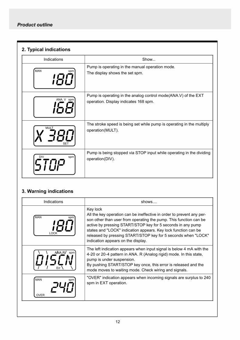
12
Product outline
2 Typical indications
3 Warning indications
Indications Show
Pump is operating in the manual operation modeThe display shows the set spm
Pump is operating in the analog control mode(ANAV) of the EXT operation Display indicates 168 spm
The stroke speed is being set while pump is operating in the multiply operation(MULT)
Pump is being stopped via STOP input while operating in the dividing operation(DIV)
MAN spm
LOCK SET mA
MAN ANA V spm
MULT
SET
DIV spm
Indications shows
Key lockAll the key operation can be ineffective in order to prevent any per-son other than user from operating the pump This function can be active by pressing STARTSTOP key for 5 seconds in any pump states and LOCK indication appears Key lock function can be released by pressing STARTSTOP key for 5 seconds when LOCK indication appears on the display
The left indication appears when input signal is below 4 mA with the 4-20 or 20-4 pattern in ANA R (Analog rigid) mode In this state pump is under suspensionBy pushing STARTSTOP key once this error is released and the mode moves to waiting mode Check wiring and signals
OVER indication appears when incoming signals are surplus to 240 spm in EXT operation
MAN spm
LOCK SET mA
ANAR
Err
spm
MAN spm
OVER
13
Installation
1 Before installation
Working without disconnecting the power supply may cause an electrical shock Before engaging upon any working procedures involving the pump be sure to turn the power supply switches off to stop the pump and the related devices
Upon becoming aware of a dangerous sign or an abnormal condition while engaging on the installation terminate the work immediately and start it from the beginning again
Do not operate the pump on the voltage which is not specified on the nameplate Failure to do so may result in damage or a fire Be sure to earth the pump
Do not place any dangerous materials or flammable objects near the pump for the sake of safety
WARNING
CAUT ION
1 Dropping the pump or subjecting it to a strong impact may result in the faulty performance Handle the pump with care Do not use the damaged pump for the prevention of the electri-cal leak or shock
2 When installing pump avoid the places where the pump is exposed to the direct sunlight the ambient temperature is above 40 digC or the relative humidity is above 85 Though the pump has a simple waterproof and dust-proof structure it is recommended to protect the pump with a cover when installing it outdoor
3
Installation
14
3 Select a level floor and use the four M6 bolts to firmly anchor the pump so as not to allow any vibration If the pump is inclined the discharge amount may decrease considerably
4 Pump should be installed in a well-ventilated place in summer and free from freezing in win-ter
6 Place the pump as close to the suction tank as possible realizing a flooded suction system (It is recommended the pump should be located lower than the suction-side tank)
7 If the pump is used to feed some liquid that gen-erates air bubbles easily (sodium hypochlorite hydrazine solution etc) the system must be positioned in a cool dark place away from direct sunlight If a tank is installed realize a flooded suction system
5 Select the installation site convenient for the future maintenance and inspection
2 Precaution for piping Piping vibrates due to the pulsation from pump Piping should be supported in order to prevent the vibra-
tion Install an air chamber or an accumulator to reduce the pulsation Ask us for further information Be careful not to have hose bend when arranging tubing It is recommended to arrange the short piping as much as possible The longer piping length the more
pressure drops and can exceed the allowable pressure of pump and can cause the over feed phenom-enon
It is recommended an automatic air bleed valve or a pressure relief valve should be installed in order to release the pressure of discharge piping for maintenance
It is recommended to install a relief valve on the discharge side piping that releases pressure automati-cally
Install a pressure gauge on the discharge side piping in order to measure the pressure inside the piping When installing EH-F pump with the flange connections or the union connections be sure to have the
connections on the discharge side fixation on wall pillar or the frame of equipment for the prevention of vibration Make sure that the piping is fixed as well
CAUTIONIncomplete fixation of pump and piping can lead to the damage to these products Significant vibration often results from the incomplete support for the discharge side connection of pump In case the direct support for the flange or union connection can not be secured try to support pump close to the discharge connection as much as possible
15
Installation
Check valve
Air bleedValve
Discharge hose
Pump
Tree way joint
Accumulator
Drain valve
Discharge valve
Back pressure valve
Pump
Suctionvalve
Air bleed valve
Airchamber
Pressure gauge
Relief valve
3 Piping1 Recommended piping drawings
Arrange piping to meet the suction and dis-charge requirement Especially pay attention to piping arrangement in case of handling the slurry which has settling property
Installation
16
Hose
Hose stopper
Fitting spacer
O ring
Fitting nut
Place hose stoppers with R surfaceface to face with fitting spacer
Hose
Hose stopperFitting spacer
O ring
Fitting nut
Fitting
Suction port
Pump head
2 Piping arrangement1 For hose connection first fit a fitting nut and then a
hose stopper and a fitting spacer in the last place If the hose stopper is not fitted properly leakage may occur and suction amount may decrease
The hose end should be secured by a hose stop-per Insert a hose end into a fitting spacer via a fitting nut and a hose stopper Then squash the hose end between the hose stopper and the fit-ting spacer Finally screw the fitting nut in
The hose stopper should be placed with its R surface face to face with the fitting spacer An incomplete hose stopper fixation or a reverse hose stopper placement can lead to leakage or insufficient suction
CAUTIONReverse hose stopper placement can dam-age hose
Fitting nut is made of plastics The fitting nut may break when it is tightened excessively
If attached hose is not long enough prepare a substitute hose such as chloroethene braided hose and polyethylene hose with a suitable bore to the hose fitting spacer
CAUTIONIt is very dangerous to attach the different size hose It may come off
Insert the fitting spacer into hose as deep as possible If the insertion is not enough hose may come off and leakage may result
Be careful not to lose the attached O rings Leakage or suction failure may result without an O ring
2 Hose connection tends to loose if liquid or ambient atmosphere is higher than normal temperature Re-tighten the fitting nut properly after starting opera-tion Be careful not to tighten the nuts too much
3 When fitting the hose again after detaching it for maintenance cut the end of hose off about 10 mm and insert it
17
Installation
4 Check valveEH-F35 45 (VCV6PC) types are attached with a check valve Fit the check valve to piping in the fol-lowing cases
1 The suction side liquid level is higher than the dis-charge side liquid level (Fig A) When injection point is below the liquid level of suction side at atmospheric pressure
2 The suction side pressure is higher than the discharge side pressure (Fig B)
3 The discharge side liquid level is higher than the suction side liquid level but the differential height between both liquid level is 5 m or below (Fig C)
4 The loading pressure of piping resistance and dis-charge head to the pump is under 013 MPa
Suction side Discharge side
Figure A
Figure B
5m
Figure C
To chemical tankor vessel
Remove check valve
3 Piping for bleedingPrior to bleeding disconnect hose and point a hose end at a suction tank or vessel Remove a check valve if it is attached on the discharge side piping
18
Installation
R12
Oslash12
5 Check valve mounting1 Tap the female thread of NPT12 at an injection
point Check valve is provided with the male thread of R12 Cut off the unused portion to fit it on a pip-ing
2 Apply seal tape on the threaded portion of the check valve and screw it in the injection point Pinch the check valve body lightly with a spanner and tighten it for easy mounting
3 When fitting a hose into a check valve with the check valve on main pipe tighten the fitting nut holding the check valve body by hand
4 Cut the end of check valve(empty 12) accordingly when mounting it in a small pipe It is recommended the end of the check valve comes at the centre of pipe bore
It is recommended to mount a check valve via a valve for maintenance Provide NPT12 female thread and screw it in Valve should be resistant to the chemical liquid in use
Valve
Check valve
Check valve body
Apply seal tape
Fitting nut
Pipe
Cut the end nozzle offif it is too long compared topipe bore
6 Flange connection and union connection1 Flange units and union sockets are packed apart from pump body Fit the flange units or the union sockets to
pump body before use Refer to the following figures2 Secure the sealing by fitting O rings to each connection
CAUTIONWhen mounting flange units or union sockets to pump body be careful not to allow O ring to get out of the groove Especially pay attention to the O ring on the groove on suction side
3 Fix the flange units or the union sockets to the pump body by tightening fitting nuts In this case first tighten the fitting nuts by the hand and then re-tighten it by 90 degrees with a spanner
CAUTION
Fitting nut is made of plastics The fitting nut may break when tightened excessively
Flange connection type
19
Instillation
Flange
Flange
Fitting nut
O ring
O ring
Elbow
Pump body
Fitting nut
Drain
Discharge
Air chamber
7 Accumulator and air chamber mountingInstall an accumulator or an air chamber on piping for the prevention of the vibration from the pulsation of pump discharge hose
20
Installation
8 Piping (General notes)1 Keep piping short and less bends Do not make the projections where air can remains
2 Support piping to avoid having the pump subject to the piping weight especially when wet-end mate-rial is made of PVC
3 In case of transferring the slurry which tends to settle do not make U shape on piping A drain plug is required at the lowest portion of piping as well
4 In case of transferring the viscous or toxic liquid or the liquid which tends to settle provide the piping for cleaning for the purpose of maintenance
5 In case of transferring the high temperature or low temperature liquid the telescopic motion of piping from temperature variation should be taken into consideration
6 Select pipe materials based on a through examination of the corrosive resistance and the estimated pressure applied to piping
7 Do not allow any adhesive agent to get in pump when connecting PVC-made pipe on the discharge side piping
8 Clean the inside of piping before installing pump in it
9 A relief valve is required to protect pump and piping Install a relief valve on the discharge piping near the pump
9 Suction piping1 Regarding suction piping a flooded suction system should be realized The bore of suction piping is
recommended to be larger than that of pump suction port
2 Each joint of suction piping needs to be mounted carefully in order to prevent air from coming in Air influx into piping may cause discharge performance failure and instability
10 Discharge piping1 Mount a relief valve on the discharge piping near pump A discharge valve should be mounted beyond
the relief valve
2 The pressure resistance of discharge piping should be higher than the set pressure of relief valve Mount each joint carefully
21
Installation
4 Electrical wiring
1 Power cord connection
Electrical works and the handling of power source must be done by qualified person
Do not operate pump with the wet hand
Make sure that power is not turned on while working on wirng
Do not dismantle electronic circuit
Electronic circuit may be broken Never apply other voltages than a rated voltage
WARNING
CAUT ION
High power equipment
CAUTION Avoid sharing a power source with a high
power equipment This can lead to the fail-ure of the electronic circuit of control unit due to extremely large surge voltage
The noise from an inverter can cause fail-ure
22
Installation
P
Surge absorption element
PNoise cut transformer
CAUTION
2 Wiring procedure
Electronic circuit of control unit may be failed by extremely large surge voltage Do not use the pump near to the high power equipment of 200V or more which may generate large surge voltage If the use of high power equipment is inevitable take either of the following measuresa Install a surge absorption element such
as varister with 2000A or more durability on the power point
b Install a noise cut transformer
CAUTION
Only qualified operatorsservice staff should be in charge of the related electrical arrange-ment and control of the power source Failure to observe this instruction may result in injury to person or damage to assets
Never connect wires while power is turned on otherwise an electrical shock or a short-circuit of controller may result Be sure to turn off power before wiring
Internal circuit is still electrified right after turning off power Take 1 minute or more to start wiring
Do not band a power cable either electrical wires or relay output wires
Earthing wire is equipped with a jumper pin Keep the jumper pin equipped in use
Do not combine the EXT or STOP signal line with a power cord or a power cable Do not com-bine power source line with the EXT or STOP signal line by a concentric cable (5 wires cable or so) Otherwise noise come about through EXT and STOP wires due to the induction effect from power cable and it may results in wrong operation or the failure of pump
Regarding frequent ON-OFF operation it is recommended to stop pump thorough STOP input terminal but not by connecting or disconnecting power source When connecting and discon-necting power cord can not be avoided it should be within 6 times an hour
23
Installation
Procedure to connect the signal cordUse DIN connector of five poles and four polesThe following connectors made by Binder in Germany are recommendedAsk IWAKI for the detail of Binder connector 5 poles 713 series 99-0436-10-05 for input signal 4 poles 715 series 99-0430-15-04 for level sensor
The following connector made by Hirschmann in Germany is recommendedAsk IWAKI for the detail of Hirschmann connector 4 poles GDS307 for output
The following procedures are based on the connector made by Binder and HirschmannIf a similar connector is used the wiring should be made according to the instruction manual of the manufacturer of connector
In case of Binder connector(1) Dismantle the connector and pass the wire through it Outer diameter of the cable should be oslash4-6
Using the different cable in diameter the connector can not be sealed properly
(2) Strip the cable ends and insert wire to the appropriate positions and connect them with screwsThe maximum allowable cross section of the wire is 075mm2
(3) After connecting the wire assemble the connector securely Slightly pull the cord to confirm that the cord connection is secured Perfect sealing can not be obtained unless the cord connection is loose
24
Installation
In case of Hirschmann connector(1) Dismantle the connector and pass the wire through it Insert a minus screw driver into the place shown by
ldquoLIFTrdquo and lift it up Outer diameter of the cable should be 35-6 mm Using the different cable in diam-eter the connector can not be sealed properly
(2) Strip the cable ends and insert wire to the appropriate positions and tighten them with screwsThe maximum allowable cross section of the wire is 075mm2
(3) After connecting wire assemble the connector securely Slightly pull the cord to confirm that the cord connection is secured Perfect sealing can not be obtained unless the cord connection is loose
Terminal position
NA Not Applicable
Connection of level sensorThe controller corresponds to two stage level sensor Connect the pre-alarm signal to Pre-STOP and the alarm signal to STOP When the pre-alarm signal comes in the orange lamp lights but the pump does not stop When a contact type is used connect wires to STOP and COM2 For open collector output level sensor Pay attention to the polarity Pre-Stop and STOP are plus (+) and COM2 is minus (-) (Max charged voltage 5V Current 18mA) For contact output level sensor Use the one designed for electronic circuit and the minimum applicable load of 1mA or less
Connection inside connector 1 STOP 2 Pre-STOP 3 Free 4 COM2
1
2
3
4 CLOSE
ON
PUMP
Level Sensor(STOP)
OPEN
Pulse
COM
+12VDC
NA
ANA(4-20)
Pre-STOP
STOP
COM
NA
OUT
25
Installation
Stop functionStop function is the function to stop the pump by the external signal Connect the wires to STOP and COM2 in the same way as the level sensor connection
CAUTION
Frequent stop and start of pump should be done by using STOP function (ON and OFF of STOP terminal) If you can not use STOP function and are forced to operate pump by turning OFF and ON of power source ON and OFF of power source should be limited to six times an hour
Pulse signal inputPulse signal input is used when the pump runs in the DIV or MULT of EXT modeDIV means dividing and MULT means multiply In case of open collector signal Pay attention to the polarity Pulse is plus (+) and COM1 is minus (-) (Max charged voltage 5V Current 18mA) In case of contact signal Use the one designed for electronic circuit and the minimum applicable load of 1mA or less
Connection inside connector 1 Free 2 Pulse 3 Free 4 12VDC 5 COM
3
2
4
15
Analog signal inputAnalog signal input is used when the pump runs in ANAR or ANAV of EXT modeANAR means analog rigid and ANAV means analog variable
Connection inside connector 1 ANA 2 Free 3 Free 4 Free 5 COM
3
2
4
15
26
Installation
Output signalOUT Photo MOS relay outputStandard is output synchronous with stroke Output is activated synchronous with each pump stroke
Connection inside connector 1 OUT 4 OUT
OUT 1
2
34
Surge voltage The electronic circuit of the control unit may be affected by excessively high surge voltage Do not operate the pump near the high-power elec-trical equipment of 200V or above that generates high surge voltage Under unavoidable circumstances take either of the following measures(1) Use a surge absorbing element (such as a
varistor with the surge resistance of 2000A or more) at the pump power supply connection
(2) Use a noise-cut transformer
Surge absorbing element
Noise-cut transformer
1 Preparation for pump operationBefore pump operation check that
bull Liquid tank is filled enough Supply liquid if it is less than the required levelbull There is no liquid leakage or congestion due to breakagebull Both suction and discharge side valves are openedbull Pump is connected to the predetermined power source correctlybull Electrical wiring is correct and there is no possibility of a short circuit or current leakage
2 BleedingBleeding is a process to eliminate the air inside the suction-side piping Be sure to carry out an air elimi-nation prior to initiating the pump operation after replacing the liquid inside a tank and after a long peri-od of storage Air gushes together with chemical liquid when carrying our bleeding For safety reasons first turn the end of a bleeding hose to a tank or a container
CAUTION
Some liquids may cause skin trouble or affect the quality of mechanical parts Wipe off chemi-cal liquid immediately when they splash on the hand or mechanical parts
27
Operation
1 Pump Operation
WA R N I N G Wear protective clothing
Wear protective clothing such as a protective mask safety gloves or so when handling chemical liquid
Do not operate pump with a discharge-side valve completely closed Operating the pump with the discharge-side valves fully closed may cause the liquid spillage or
the extremely high pressure inside the pump or the discharge-side pipingtubing This could lead to a piping burst Be sure not to operate pump with the discharge-sides valve closed
CAU T I O N A long time dry running (longer than 30 minutes) may cause the pump overheat and it could lead
to the deformation of the pump unit consists of a pump head and valve cases or so or may loosen the pump head fitting and result in liquid leakage
If the hex socket cap bolts on a pump head are loosened liquid leakage may resultBe sure to fasten all the 6 or 8 hex socket cap bolts tightly before starting the initial pump opera-tion And periodically check the looseness of the bolts on the pump head and retight the bolts as necessary
bull Tightening torque255NbullmTighten all the bolts diagonally applying equal tightness
If electric wiring gets wet due to accidental liquid spillage fire or electrical shock may occur Never get it wet When the electric wiring gets wet turn off power and wipe the liquid away
A frequent ON-OFF operation should be conducted by using STOP function(ON - OFF signals to STOP terminal) In case the STOP function is not available for the ON-OFF operation the ON - OFF operation by turning onoff power should be limited to six times an hour
4
28
3 Procedure for bleeding
Check valve should be removed
To tank or drain pan
100
75
50
25
0 25 50 75 100
(Fixed stroke length)
Stroke length adjustment
240spm
180spm
120spm
Flow
rate
Operation
[1] Extend the tube connected to the discharge-side fitting nut of pump to a chemical tank or a drain pan Then start pump operationbull Remove a check valve if it is installed on dis-
charge-side
[2] Operate the pump for about 10 minutes to eliminate air completely
[3] When the air in pump head is completely eliminated and liquid is replaced return the discharge-side tube to the regular tubing position
[4] Finally make sure there is no leakage in any section
4 Discharge capacity adjustmentDischarge capacity can be adjusted by both the stroke length adjustment and the stroke rate adjust-ment but basically adjust it via the stroke rate adjustment Stroke length adjustment is an auxiliary way to cover the range where the stroke rate adjustment can not reachPay attention to the following for correct procedure
Stroke rate adjustment(1) For some liquids which diffuses gas such as sodium hypochlorite and hydrazine solution adjust discharge capac-
ity by means of the stroke rate adjustment with the stroke length about 100 Gas lock may occur if the stroke length is set to short
(2) When the back pressure on discharge side is high adjust discharge capacity by the stroke rate adjustment with the stroke length about 100
(3) In case reaction is greatly influenced depending on the discharge capacity per pump shot in the application of neutralization or titration adjust discharge capacity by the stroke rate adjustment with the shortened stroke length and reduce the discharge capacity per shot
1 Discharge capacity adjustment procedureAppropriate stroke length and stroke rate are decided on the pump operating condition and liquid characteristics Following ways are recommended for proper calibration
(1) Set stroke length at 100 and roughly adjust discharge capacity by adjusting stroke rate
(2) Measure discharge capacity(3) If the measured capacity is below the wanted value
increase the stroke rate and measure again the dis-charge capacity
(4) Adjust stroke length for the fine adjustment of discharge capacity(5) Determine a discharge capacity at the last and confirm the wanted capacity is discharged
CAUTION
29
100
75
50
25
0 60 120 180 240spm
Fixed stroke length
Stroke rate adjustment
Flow
rate
Screw driverOPEN
LOCK
100
75
50
25
0 25 50 75 100
Fixed stroke rate
Flow
rate
Stroke length adjustment
Operation
2 Stroke rate adjustmentStroke rate is adjusted by the key operations of control unit Control the plunger stroke rate per minute from 1 to 240 spm via control unit
3 Stroke length adjustmentStroke length adjustment knob is locked with a screw Loosen the screw before adjustment and lock it afterwards
(1) Turn on pump and adjust the discharge capacity by turning the stroke length adjusting knob while pump is running
(2) The left graph shows the relation between stroke length and discharge capacity The maximum dis-charge capacity is shown on the name plate
bull The usage between 40 and 100 is practi-cal
Do not turn the stroke length adjusting knob when pump stops
CAUTIONBe sure to tighten the screw on the adjust-ment knob after an adjustment The knob may rotate unintentionally due to a loose fixation This may result in the fluctuation in a discharge rate
30
Mode ParameterDefault value
Setting range Step
Manual operation Stroke speed 240 1-240DIV setting Dividing ratio frasl 1 1-9999
MULT setting Multiply ratio times1 times1-9999ANA R setting 4-20 4-20 20-4 0-20 20-0
ANA V setting
P1 amperage 40 00-200P1 stroke speed 0 0-240P2 amperage 200 00-200P2 stroke speed 240 0-240
User setting
EXT operation ANA V DIV MULT ANA R ANA V
Anti-chatteringMECH MECH ELECST05 ST05 ST20 ST50FT01 FT02 FT04
Buffer memory MEM-N MEM-N MEM-Y
111-
011
011
2 Control unit operationEH-F type pump is controlled by means of setting or changing the setting values of the controller Control functions are various at each operation mode Read this section carefully before operation
Default parameter values
5 Full operationPut pump in use after bleeding and adjusting discharge capacityPump runs in manual operation or in accordance with the setting of control unit
6 Manual operationStarting pump After turning on power ON lamp (Green) appears and display shows WAIT mode For
the first time to turn on power MAN lamp appears and pump starts after pushing STARTSTOP key once
Stop pump Push STARTSTOP key to turn off MAN lamp and stop pump Pump starts and stops every time STARTSTOP key is pressed
7 EXT operationRefer to the next section of 2 Control unit operation
8 Shout down When pump will not in use for a long time (one month or more)
Run pump with clean water about 30 minutes in order to clean the wet-end parts and the inside of pip-ing before storage
When re-starting pump after a long time storage If pump dose not suck up liquid clean valve sets and remove the sticking foreign matters Carry out an air elimination and adjust discharge capacity when air stays inside pump head Refer to page 28 3 Procedure for bleeding
Operation
---
-
31
AN
A V
(Ana
log
var
iabl
e)
DIV
(Pul
se d
ivid
ing)
MU
LT(P
ulse
mul
tiply
)A
NA
R(A
nalo
g ri
gid)
SE
TS
ET
Use
r mod
e
EX
T m
ode
sele
ctio
n
EX
T
EX
TE
XT
EX
TE
XT
EX
T EX
T
EX
T
EX
T
EX
T
EX
T
EX
T
EX
T
EX
T
EX
T
EX
T
EX
T
EX
T
3 sec
onds
or m
ore
Wai
t mod
e
Set
ting
of fi
xatio
n pa
ttern
EX
T m
ode
Man
ual o
pera
tion
Set
ting
of s
troke
num
ber
AN
A R
(Ana
log
rigi
d)M
ULT
(Pul
se m
ultip
ly)
DIV
(Pul
se
div
idin
g)
AN
A V
(Ana
log
var
iabl
e)
anti-
chat
terin
gse
tting
dis
play
Setti
ng o
f div
idin
g ra
tioS
ettin
g of
cou
nt n
umbe
r
Curre
nt va
lue of
P1
Stro
ke nu
mbe
r of P
1
Curre
nt va
lue
of P
2
Stro
ke nu
mbe
r of P
2
EX
T O
pera
tion
Dis
play
EX
T se
tting
mod
e
Buf
fer m
emor
yse
tting
dis
play
Pow
er O
N
spm
MA
Nsp
m
spm
DIV
DIV
SE
TS
ET
MU
LT
MU
LTsp
mA
NA
V
spm
AN
AR
AN
AR
SE
Tm
AS
ET
mA
spm
AN
A
V
P1
mA
SE
T
spm
AN
A
V
P1
AN
AR
SE
Tm
A
AN
AR
SE
Tm
AS
ET
AN
A
V
P 2
SE
T
spm
AN
A
V
P 2
AN
AR
SE
Tm
A
AN
A
V
SE
TS
ET
SE
T
SE
T
SE
T
SE
T
SE
T
SE
T
SE
T
SE
T
SE
TS
ET
1 Overview Operating Scheme
Operation
1 means automatic transfer WAIT mode is selected when the power is switched on for the first time On and after the initial power activation pump restores the previous status right before the power is switched off
2 Regarding MANUAL mode pump starts operation by pushing STARTSTOP key at WAIT modePushing STARTSTOP key again the pump stops and returns to WAIT mode
3 Regarding EXT operation pushing EXT key at WAIT mode the pump moves to EXT mode and starts operationPushing STARTSTOP key stops the operation and returns the pump to WAIT mode
4 The change of each setting of EXT operation is accessible by pushing EXT key at EXT mode Pushing EXT key after the setting pump starts in EXT operation according to the changed setting
5 Pushing EXT key for 3 seconds at WAIT mode pump moves to USER mode At USER mode the EXT mode selection and the detailed setting such as the setting of buffer memory or so can be obtained
For details refer to each section of 2 Pump operation
2 Pump operation1 Operation of controller
Before turning on power confirm the specified power source on the nameplate
CAUTION
Connecting any other powers than the one shown on nameplate to pump is strictly prohibitedIt could lead to pump trouble or failure
Operation
32
1 Turning on powerDisplay shows WAIT mode when pump is turned on for the first time After the initial power activation the pump restores the previous mode right before the power was turned off last time If power is turned off at any setting modes WAIT mode appears at the next power activation
Stroke speed setting value is shown on display at WAIT mode ON lamp lights (Green)
EXT
EH-F ControllerSTARTSTOP
ON STOP
spm
33
2 Manual operation(1) Stroke speed can be adjusted by and
keys The figure changes quickly when either or key is depressed The picture below
shows the stroke speed is set to 160 spm
EXT
EH-F ControllerSTARTSTOP
ON STOP
spm
EXT
EH-F ControllerSTARTSTOP
ON STOP
MAN spm
EXT
EH-F ControllerSTARTSTOP
ON STOP
spm
(2) Push STARTSTOP key once to start the pump operation MAN indication appears and ON lamp blinks synchronously with each stroke
(3) MAN indication disappears and ON lamp stops blinking as STARTSTOP key is pushed again Pump enters WAIT mode
Operation
Operation
34
EXT
EH-F ControllerSTARTSTOP
ON STOP
ANA V
P1 SET mA
EXT
EH-F ControllerSTARTSTOP
ON STOP
P1 SET
ANA V spm
EXT
EH-F ControllerSTARTSTOP
ON STOP
spm
EXT
EH-F ControllerSTARTSTOP
ON STOP
ANA V spm
(4) Set the current value at P1 Figure increases or decreases as or key is pushed The pic-ture below shows 80 mA is set to point 1
EXT
EH-F ControllerSTARTSTOP
ON STOP
ANA V
P1 SET mA
(5) Pushing EXT key once spm appears on the display while mA disappears The picture below shows the number of strokes at P1
EXT
EH-F ControllerSTARTSTOP
ON STOP
P1 SET
ANA V spm
3 EXT operation (ANA V mode)(1) Push STARTSTOP key to move to WAIT mode
if pump is in another mode Go to next step if pump is in WAIT mode
(2) ANAV indication appears and pump enters an EXT mode as EXT key is pushed once Pump starts operation in accordance with current sig-nals and various settings ON lamp blinks at each pumping during operation Pump is con-trolled via the EXT mode which was select-ed at USER mode The initial setting of EXT mode is ANA V mode Select a preferable EXT mode in USER mode The picture below shows ANA V mode (The spm on the display changes according to input signals)
(3) Push EXT key once when pump is running in ANA V mode Display indicates the setting display of ANA V mode spm indication dis-appears and P1 SET and mA indications appear on the screen
(6) Set the number of strokes at P1 Figure increasesdecreases as key is pushed Picture below shows 10 spm is set for point 1
Operation
35
(7) Push EXT key to move to the setting display of the current value at P2 P1 and spm disap-pear and P2 and mA appears instead
EXT
EH-F ControllerSTARTSTOP
ON STOP
ANA V
P 2 SET mA
EXT
EH-F ControllerSTARTSTOP
ON STOP
ANA V
P 2 SET mA
EXT
EH-F ControllerSTARTSTOP
ON STOP
P 2 SET
ANA V spm
(11) Push EXT key to return to EXT mode Pump starts to run in ANA V mode on the setting of (4) through (10) ON lamp starts to blink at each pumping
EXT
EH-F ControllerSTARTSTOP
STOPON
ANA V spm
EXT
EH-F ControllerSTARTSTOP
ON STOP
P 2 SET
ANA V spm
EXT
EH-F ControllerSTARTSTOP
ON STOP
spm
(8) Set the current value of P2 by pushing and keys Picture below shows 180 mA is set to
point2
(9) Pushing EXT key once spm appears on the display while mA disappears The picture below shows the number of strokes at P2
(10) Set the number of strokes at P2 by pushing and keys Picture below shows 200
spm is set to point 2
(12) Pushing STARTSTOP key pump enters WAIT mode and pump stops ON lamp stops blink-ing and ANAV indication disappears
CAUTIONWhen the setting of the buffer memory is OFF keep the number of strokes in the dividing operation 240 spm or below The input signals to operate the pump over 240 spm can cause an unstable pump operationWhen the setting of the buffer memory is ON the pump operates for all the input pulse signalsPump keeps operating after all the signals are stopped in this case Be careful when setting of buffer memory
Operation
36
EXT
EH-F ControllerSTARTSTOP
ON STOP
DIV
SET
EXT
EH-F ControllerSTARTSTOP
ON STOP
DIV
SET
EXT
EH-F ControllerSTARTSTOP
STOPON
DIV spm
EXT
EH-F ControllerSTARTSTOP
ON STOP
spm
(2) Pushing EXT key DIV appears and pump starts operation in the ratio of input pulse sig-nals a pumping ON lamp blinks synchronous-ly at each pumping The initial setting of EXT selection is ANA V mode Change mode to DIV mode via USER mode Refer to P 40 for detail information
(3) Push EXT key while pump is operating in DIV mode Pump stop running and SET indication appears on the DIV setting display in stead of spm indication
(4) Enter a dividing ratioFigure increasesdecreases when key is pushed The picture below shows 10 is set
4 EXT operation (DIV mode)
(1) Push STARTSTOP key to move to WAIT mode if pump is in another mode Go to next step if pump is in WAIT mode
CAUTIONOn condition the setting of buffer memory is OFF do not input any pulse signals during the pumping motions for a input pulse signal in the multiply operation These input pulse signals are cancelledWhen the setting of buffer memory is ON pump operates for all the input pulse signals
Operation
37
EXT
EH-F ControllerSTARTSTOP
ON STOP
spm
EXT
EH-F ControllerSTARTSTOP
STOPON
DIV spm
EXT
EH-F ControllerSTARTSTOP
ON STOP
spm
EXT
EH-F ControllerSTARTSTOP
ON STOP
MULT
(5) Push EXT key to return to EXT operating mode Pump starts to run on the setting at item (4) ON lamp blinks synchronously at each pumping
(6) Pushing STARTSTOP key pump enters WAIT mode and pump stopsDIV indication disappears and ON lamp stops blinking
5 EXT operation (MULT mode)
(2) MULT indication appears and pump starts running in an EXT operation mode in the ratio of an input pulse signal pumpings as press-ing EXT key ON lamp blinks at each pump-ing Display shows the rest of the number of strokes In MULT mode the number of strokes is equal to the setting value in manual opera-tionThe initial setting of the EXT mode selection is ANA V mode which is the operation in pro-portion to current First select MULT mode via USER mode Refer to P 40 for detail informa-tion
(1) Push STARTSTOP key to move to WAIT mode if pump is in another mode Go to next step if pump is in WAIT mode
Operation
38
EXT
EH-F ControllerSTARTSTOP
ON STOP
spmEXT
EH-F ControllerSTARTSTOP
ON STOP
ANAR spm
EXT
EH-F ControllerSTARTSTOP
ON STOP
MULT
SET
EXT
EH-F ControllerSTARTSTOP
ON STOP
MULT
EXT
EH-F ControllerSTARTSTOP
ON STOP
spm
EXT
EH-F ControllerSTARTSTOP
ON STOP
MULT
SET
(5) Push EXT key to return to MULT mode(3) Pushing EXT key when pump is running in the multiply operation calls the setting display of MULT mode and SET indication appearsPump stops running and ON lamp stop blinking
(4) Enter the number of pumpings per input signalFigure increasesdecreases when key is pushed The picture below shows the pump-ing number is set to 1800 times per an input signal
6 EXT operation (ANA R mode)(1) Push STARTSTOP key to move to WAIT mode
if it is in another mode Go to next step if it is in WAIT mode
(6) Pushing STARTSTOP key recalls WAIT mode and pump stops spm indication appears in stead of MULT indication
(2) Pushing EXT key ANAR appears and pump starts running in the ratio of an input pulse sig-nal pumpings ON lamp blinks at each pump-ing The initial setting of the EXT mode selec-tion is ANA V mode which is the operation in proportion to current is selected First select ANA R mode in USER mode Refer to P 40 for more information
Operation
39
EXT
EH-F ControllerSTARTSTOP
ON STOP
ANAR
SET mA
EXT
EH-F ControllerSTARTSTOP
ON STOP
ANAR spm
EXT
EH-F ControllerSTARTSTOP
ON STOP
ANAR
SET mA
EXT
EH-F ControllerSTARTSTOP
ON STOP
spm
(4) Figure increasesdecreases when key is pushed The picture below is when it is set to 0-240 spm for 20-4 mA
(5) Push EXT key to return to EXT mode Pump starts to run on the setting at item (4) ON lamp blinks synchronously at each pumping
(6) When pushing STARTSTOP key pump enters WAIT mode and stops running ON lamp stops blinking and ANAR disappears
(3) Pushing EXT key when pump is running in the multiply operation calls the setting display of ANAR mode and SET and mA indications appear while spm disappears Pump stops running and ON lamp stops blinking
Operation
40
EXT
EH-F ControllerSTARTSTOP
ON STOP
ANA V
(5) Push EXT key to confirm the desired EXT mode Pump displays the EXT mode selection The picture below shows DIV appears to indi-cate DIV mode is selected
EXT
EH-F ControllerSTARTSTOP
ON STOP
DIV
EXT
EH-F ControllerSTARTSTOP
ON STOP
SET
EXT
EH-F ControllerSTARTSTOP
ON STOP
spm
EXT
EH-F ControllerSTARTSTOP
ON STOP
spm
EXT
EH-F ControllerSTARTSTOP
ON STOP
SET
7 USER settingThe setting of each function is changed in USER mode Have the pump entering WAIT mode in order to move to USER mode OUT (Output) is synchronous with spm and it can not be changed
7-1 EXT mode selection Any one of DIV (pulse dividing) MULT (pulse multiply) ANAR (analog rigid) or ANAV (analog vari-able) can be active in EXT mode The initial mode when shipped from factory is ANAV
(1) Push STARTSTOP key to move to WAIT mode if it is in another mode If it is in WAIT mode go to next step
(2) Press EXT key for more than 3 seconds to move to USER mode The picture below shows pump enters the EXT mode selection
(3) Pushing EXT key SET appears and display shows the mode currently set Picture below shows ANA V mode is selected
(4) Push or key to select a desired EXT mode The picture below shows DIV mode is selected
(6) Push STARTSTOP key to move to WAIT mode spm appears while DIV goes out
Operation
41
EXT
EH-F ControllerSTARTSTOP
ON STOP
spm
EXT
EH-F ControllerSTARTSTOP
ON STOP
ANA V
EXT
EH-F ControllerSTARTSTOP
ON STOP
SET
(3) Push key once
EXT
EH-F ControllerSTARTSTOP
ON STOP
(4) Push key again to move to the anti-chatter-ing setting display
EXT
EH-F ControllerSTARTSTOP
ON STOP
(5) Pushing EXT key display shows the mode cur-rently set and SET appears on it The picture below shows when MECH is selected
EXT
EH-F ControllerSTARTSTOP
ON STOP
SET
7-2 Setting of anti-chattering Anti-chattering function is settable against the incoming pulses during the DIV or MULT operation For the long chattering of mechanical contact such as relay set a large figure via MECH For the high speed (high frequency) chattering of the semi-conductor type contact such as transistor set a small figure via ELEC ST05 of MECH is initial setting
(6) Select MECH by or key for a mechani-cal contact And select ELEC for a semi-conductor contact The picture below shows ELEC is selected
(1) Push STARTSTOP key to move to WAIT mode if it is in another mode If it is in WAIT mode go to next step
(2) Press EXT key for more than 3 seconds to move to USER mode The picture below shows pump enters the EXT mode selection
Operation
42
EXT
EH-F ControllerSTARTSTOP
ON STOP
SET
(7) Push EXT key to display the current set state The picture below shows FT01 is selected
EXT
EH-F ControllerSTARTSTOP
ON STOP
SET EXT
EH-F ControllerSTARTSTOP
ON STOP
EXT
EH-F ControllerSTARTSTOP
ON STOP
spm
7-3 Setting of buffer memoryIn case pump operation can not catch up with the input pulse signals in DIV or MULT operation exces-sive pulse signals can be put in memory up to 65535 pulses However the excessive pulses can not be restored if once power is off or mode is changed
EXT
EH-F ControllerSTARTSTOP
ON STOP
spm
(2) Press EXT key for 3 seconds or more to move to USER mode The picture below shows the EXT mode selection display
EXT
EH-F ControllerSTARTSTOP
ON STOP
ANA V
(8) Set a large figure for the long chattering by or key and set a small figure for high speed (high frequency) chattering The picture below shows FT04 is selected
(9) Push EXT key to return to the anti-chattering setting display SET indication disappears
(10) Push STARTSTOP key to return to wait mode spm indication appears
(1) Push STARTSTOP key to move to WAIT mode if it is in another mode If it is in WAIT mode go to next
Operation
43
(3) Push key once
EXT
EH-F ControllerSTARTSTOP
ON STOP
(7) Push or key in order to set buffer memo-ry to ON or OFF Select MEM-Y to set it ON Select MEM-N for OFF setting The picture below shows when ON is set
EXT
EH-F ControllerSTARTSTOP
ON STOP
SET
(4) Push key once again
EXT
EH-F ControllerSTARTSTOP
ON STOP
(8) Push EXT key to return to the buffer memory setting display SET indication disappears
EXT
EH-F ControllerSTARTSTOP
ON STOP
(9) Push STARTSTOP key to return to WAIT mode spm indication appears
EXT
EH-F ControllerSTARTSTOP
ON STOP
spm
(5) Push key once again and the buffer memory setting display is shown
EXT
EH-F ControllerSTARTSTOP
ON STOP
(6) Push EXT key in order to display the current set state SET indication appears The picture below shows the buffer memory is set to OFF
EXT
EH-F ControllerSTARTSTOP
ON STOP
SET
Operation
44
8 Bleeding amp self-primingAt WAIT mode Manual operating mode and EXT operating mode pump operates at max speed tak-ing priority over any functions when both and keys are pushed at once Pump runs at max speed only when both keys are depressed Pump state returns to the previous mode once either or key is released Pressing and keys for 10 seconds keeps pump running at maximum speed In this state this fixation is released when pushing either or key once and pump returns to the previous mode
(1) When pump is running in ANAV mode
EXT
EH-F ControllerSTARTSTOP
ON STOP
ANA V spm
(2) Pump start to run at full speed when and keys are pressed at once Display shows
PRIME If either or key is released pump returns to the previous mode In this case pump returns to ANAV mode
EXT
EH-F ControllerSTARTSTOP
ON STOP
ANA V
(3) Pressing both and keys simultaneously for 10 seconds or more pump continues to run at full speed even if both keys are released In this case indication appearsPush either or key to release this state indication disappears and pump returns to the previous mode In this case pump returns to ANAV mode
EXT
EH-F ControllerSTARTSTOP
ON STOP
ANA V
Operation
45
10 Error display and release(1) In case Input signals fall to 4 mA or below while
4-20 or 20-4 is set to ANA R mode pump stops with DISCN blinking and Err on dis-play
(2) This error state can be released by push-ing STARTSTOP key and pumps enters wait mode In this case check the wiring and input signals
EXT
EH-F ControllerSTARTSTOP
ON STOP
ANAR
Err
spm
EXT
EH-F ControllerSTARTSTOP
ON STOP
spm
9 Key lockKey lock function is to prevent pump from being operated by some other person than user If STARTSTOP key is pressed for five seconds or more when pump is running or stops all key operations become ineffective with LOCK indication on display This function can be released by pressing STARTSTOP key for 5 seconds while LOCK lights
EXT
EH-F ControllerSTARTSTOP
ON STOP
MAN spm
LOCK
46
Do not conduct a maintenance work with the wet hands It can cause an electric shock
Before dismantling pump be sure to turn off power and check the pump is not electrified Do not
start a dismantlement work after stopping the pump by pushing the STARTSTOP key only Put up
the sign of ldquoMaintenance work is in progressrdquo in order to prevent a pump switch from turning on
unintentionally during the work Release the pressure of discharge piping and drain the liquid from
the wet end parts And then clean the inside of pump head
Wear protective clothing such as a protective mask globes goggles and chemical-proof wear
according to the handled chemical liquid during the work
WARNING
5 Maintenance
1 Trouble shootingTrouble Cause Troubleshooting
Pump dose not start Faulty wiring or disconnection in wiring Voltage is too low Failure in the electronic circuit of control unit
Pump dose not suck liquidDischarge amount is low
Air suction from suction piping Valve gasket is not installed Valve set assembling direction is wrong Pump is air-locked Pump stroke length is too short Suction-sidedischarge-side valve is clogged with
foreign matter Adhesion of valve onto valve seat
Discharge amount fluctuates
Liquid leaks
Key operation is ineffective Key is locked Release key lock
Pump doesnt run
Pump is in waiting mode Signals are not coming for EXT operation Pump is in EXT setting mode Pump is suspended with STOP
Move to operation mode Check wiring and correct the wrong part Move to EXT operating mode Release STOP function
Abnormal noise
Suction-sidedischarge-side valve is clogged with foreign matters
The sound absorption gasket is worn out Bearing is worn out Spring is damaged
Piping vibrates due to pulsation Bearing is worn out Spring is damaged
Install a accumulator or an air chamber The end of pump life span The end of pump life span
Suction-sidedischarge-side valve is clogged with foreign matters
Air is trapped in pump Overfeeding Diaphragm is damaged
Fittings are not tightly closed Pump head is not tightened Diaphragm is damaged O ring and valve gasket are not installed O ring is damaged
Correct wiring Inspect power source and provide measurement Replace the whole unit
Arrange piping again Install valve gasket Reassemble valve set Carry out air elimination Drive pump with 100 stroke length to prime liquid Then
reset stroke length Disassemble inspect and clean Disassemble inspect and clean
Tighten fittings Tighten pump head Replace diaphragm Install O ring and valve gasket Replace O ring
Disassemble inspect and clean
Carry out air elimination Install a check valve or a back pressure valve Replace diaphragm
Disassemble inspect and clean
The end of pump life span The end of pump life span The end of pump life span
Abnormal vibration
Input pulse can not be read Signals are not coming Anti-chattering setting is not proper
Check wiring and correct the wrong part Change the setting properly
Analog signal input can not be read
Wrong wiring Signals are over acceptable loaded resistance
Check wiring and correct wrong part The load resistance is 200Ω Use some devise which can
accept the load resistance
47
CAUTION Check periodically whether the bolts fixing pump head are tightened Tighten them as needed
The bolts fixing pump head may loosen in operation Tightening torque 255Nbullm
Maintenance
3
bull Tighten joint where leakage has occurredbull The excessive air bubbles in the discharged liquid mean air suc-
tion has been caused in system Examine the piping and tighten joint on where leaks
Is there liquid leakage or air suction at any joints on pump or piping
2 Maintenance and inspection
1 Daily inspectionPay attention to the following points during pump operation Stop pump immediately upon detecting abnormality and take measures according to the item Troubleshooting When wear parts come to the life time replace them by new ones
No
1
2
Check Point Description
Does pump lift liquid normally
bull Is liquid normally fedbull Is suction pressuredischarge pressure at normal levelbull Has liquid undergone quality change crystallization or solidifica-
tion
Abnormal noise or vibrationbull Abnormal noise or vibration may happen from the abnormal func-
tioning of pump
EXT setting can not be stored
After EXT setting STARTSTOP key is pushed for EXT by mistake
Push EXT key to operate pump in EXT mode
ldquoPRIME is kept indicated and other operations are inac-cessible
Self-priming function is active Push either or key to release the function
Analog signal input can not be read and DISCN indication appears
Wrong wiring or disconnection Check wiring and correct the wrong part Refer to page 45
for how to release an error indication
Trouble Cause Troubleshooting
48
Maintenance
2 Wear partsWear parts should be replaced in proper period for a long period of pump operation It is recommended that follow-ing parts are always ready for the replacementVC V6 PC P6 types
Parts Qty Life span
Pum
p he
ad
Valve set
EH-F35 EH-F45 EH-F55middot70
2sets
8000hours
Diaphragm 1
Refer to exploded view
Bac
k pr
essu
re v
alve
1
2
Che
ck v
alve
7 6 1
8 11 1
Diaphragm seat 1
O ring
Poppet check valve (With check gasket)
Check valve spring Spacer
Diaphragm
O ring
Note Durability of wear parts depend on the pumped liquid temperature and pressure Time to be replaced mentioned as above is the estimation obtained by continuous pump-ing of clean water at ambient temperature
8000hours
4000hours
49
3 Dismantlement and assembly
Getting wet with or coming in contact with chemicals and toxic liquid is harmful Wear protective clothing such as a protective mask globes goggles and chemical-proof wear during the work
Risk of electrical shock Be sure to turn off power and confirm that pump and devices are not electrified before the work
Release the pressure inside pump and a discharge hose by opening an air bleed valve on piping prior to loosening the piping connections or the dismantlement of pump Dismantlement with the pressure inside pump could lead to liquid spillage
Be careful not to touch residual liquid when dismantling pump Some liquids are harmful for skin or component parts Wipe off liquid when the hand or the component parts come in contact with liquid
WARNING
CAUT ION
Hose
Hose stopperFitting spacer
O ring
Fitting nut
Fitting
Pumphead
Remove the fittingwith a spanner
1 Valve set replacement Dismantlement1 Loosen a fitting nut and remove the hose con-
nected to pump head Pay attention to the liquid dripping
2 Loosen a fitting with a spanner to remove it Then detach the valve set from pump head
Maintenance
50
AssemblyAssembly procedure is in reverse order to disas-sembly Pay attention to the following when assembling valve set DispositionInsertion direction of valve set The wrong dispositioninsertion direction of valve
set component can lead to leakage and less dis-charge amount
O ring is fitted properly1 Discharge side valve set mounting
Put valve set in pump head and screw a fitting into a pump head by hand and then re-tighten it by 14 turns with a spanner
2 Suction side valve set mountingPut valve set in connection port and screw the fitting into pump head by hand and then re-tighten it by 14 turns with spanner
Note Pay attention to the mounting direction of the spacer fitted to EH-F45(VC V6 PC)Make sure the cut portion on the spacer of suction side should be downward the one of discharge side should be upward
Suction side
Discharge side
O ringValve gasket
Valve gasket
Valve gasket
Valve guideValveValve seatSpacer
O ring
Valve gasketValve guideValveValve seat
Spacer
1714
11
1312
11
1312
17
17
14
14
14
11
31
1312
31
17
14
11
1312
12
13
11
14
EH-F35
EH-F45
EH-F5570
Suct
ion
side
Dis
char
ge s
ide
For b
oth
suct
ion
and
disc
harg
e si
deFo
r bot
h su
ctio
nan
d di
scha
rge
side
VC V6 PC P6 Type
Maintenance
51
Pay attention not to lose diaphragm spacer and to apply the correct number of diaphragm spacers 0 to several pieces of diaphragm spacers are put between retainer and plunger to adjust the position of diaphragm The number of spacers mounted depends on the pump model There are the models which do not have spacers
Maintenance
2 Diaphragm replacement Dismantlement1 Set stroke length to 0 by adjusting stroke length
adjustment knob
2 Remove the pump head from the pump body by loos-ening hex socket cap bolts
3 Rotate a diaphragm anti-clockwise to remove it from a plunger pin The diaphragm is screwed into the plunger pin
AssemblyAssembly is done in reverse order to disassembly Follow the steps below1 Make sure the stroke length of pump is set to 0
prior to an assembly Operate pump to set the stroke length to 0 and
stop it Then turn off power
2 Fit a rear diaphragm seat a retainer and a diaphragm spacer into new diaphragm via the threaded pin and screw the diaphragm into the plunger pin
Fit the concave side of retainer into the convex side of diaphragm Pay attention the retainer dose not come off
3 Set the stroke length to 100 Operate pump to set the stroke length to 100
and stop it Then turn off power4 Install a pump head to a pump body by tightening
the hex sock cap bolts equally Tightening torque is 255Nbullm
52
4 Accessories1 Connection port bore bull Check valve bull Back pressure valve
Note1 Check valves and back pressure valves are options2 Regarding the connection of the discharge side of back pressure valve
NPT38 and NPT12 taper pipe thread is used for BV-N-CR
Pump type Connection port bore Check valve Back pressure valve
EH-F35VC empty38timesempty12 hose CA-3VCH-C6 ndash
empty38timesempty12 hose CA-3VEH-C6 ndashempty38timesempty12 hose CA-3VH-C6 ndashempty38timesempty12 hose CA-3VCH-C6 ndashempty38timesempty12 hose CA-3VEH-C6 ndashempty38timesempty12 hose CA-3VH-C6 ndash
V6
empty38timesempty12 hose ndash BV-3NV-C6Rempty38timesempty12 hose ndash BV-3NE-C6Rempty38timesempty12 hose ndash BV-3NPV-C6Rempty58timesempty34 hose ndash BV-3NV-C7Rempty58timesempty34 hose ndash BV-3NE-C7Rempty58timesempty34 hose ndash BV-3NPV-C7R
PC
EH-F45VCV6PC
EH-F55VCV6PC
EH-F70VCV6PC
Maintenance
53
Maintenance
5 Exploded view
1 General view The extent of dismantlement is within the following exploded view
Diaphragm spacer
Retainer
(Back up retainer)55 bull 70 types
Pump body
Valve set
Valve set
Pump head
Diaphragm
Rear diaphragm sheet
54
2 Pump head (Hose connection type)
EH-F45 type EH-F35 type
4
28
2930
3
1114
131211
131217
1897
1
17
111312111312
3
3029
28
4
1920
1920 21
17
111312
31
3
3029
28
4
131217
189
7
11
3114
14
4
282930
3
1
21
1515
EH-F55 type
4
28
2930
3
11
131217
18
9
7
10
1
1920 21
17
111312
3
30
29
28
4
EH-F70 type
4
28
2930
3
14
11131217
18
9
7
10
1
1920 21 17
111312
3
30
29
28
4
15 15
14
1414
14
14 14
Note1 The back up retainer of No10 is only for EH-F55 bull 70 typesNote2 The figure inside ( ) in the above table is for EH-F45 bull 55 bull 70 typesNote3 The number of the diaphragm spacers (No18) is not constant None or a few spacers is inserted at
each diaphragmNote4 The figure inside ( ) in the above table is for EH-F70Note5 EH-F35 bull 55 bull 70 (VC V6 PC ) types require 2 valve gaskets and EH-F45 (VC V6 PC) types
require 4 of themNote6 The spacer on No31 is for EH-F45 type only
No Name Qty1 Pump head 13 Fitting 24 Fitting nut 27 Diaphragm 19 Retainer 110 Back up retainer 1 Note111 Valve guide 4 (2) Note212 Valve seat13 Valve14 Valve gasket
No Name Qty
17 O ring 218 Diaphragm spacer 1 Note319 Hex socket head bolt 6 (8) Note420 Spring washer21 Plain washer28 Hose stopper 229 Fitting spacer 230 O ring 231 Spacer 2 Note6
15 Rear diaphragm seat 1
2 (4) Note54 (2) Note24 (2) Note2
6 (8) Note46 (8) Note4
Maintenance
55
Maintenance
3 Pump head (Flange connection type) EH-F55 type
30
3
11
131217
18
9
7
10
1
1920 21
17
11
1312
3
30
EH-F70 type
15
EH-F45 type EH-F35 type
30
3
11131211
131217
1897
1
17
11131211
1312
3
30
1920
1920 21
17
111312
31
3
131217
189
7
11
31
30
3
1
30
21
1515
30
3
11131217
18
9
7
10
1
1920 21 17
11
1312
3
30
15
32
33
33
32
4
32
433
43332
32
334
43332
32
33
32
334
44
1414
14 14 14
1414
14
14 14
NoNo Name Qty1 Pump head 13 Fitting 24 Fitting nut 27 Diaphragm 19 Retainer 110 Back up retainer 1 Note111 Valve guide 4(2)Note212 Valve seat 4(2)Note213 Valve 4(2)Note214 Valve gasket 2(4)Note5
Name Qty
17 O ring 218 Diaphragm spacer 1 Note319 Hex socket cap bolt 6(8)Note420 Spring washer 6(8)Note421 Plain washer 6(8)Note430 O ring 2
33 Union 2
31 Spacer 2 Note6
15 Rear diaphragm seat 1
32 Flange 2
Note1 The back up retainer of No10 is only for EH-F55 bull 70 typesNote2 The figure inside ( ) in the above table is for EH-F45 bull 55 bull 70 typesNote3 The number of the diaphragm spacers (No18) is not constant None or a few spacers is inserted at
each diaphragmNote4 The figure inside ( ) in the above table is for EH-F70Note5 EH-F35 bull 55 bull 70 (VC V6 ) types require 2 valve gaskets and EH-F45 (VC V6) types require 4 of
themNote6 The spacer on No31 is for EH-F45 type only
56
4 Pump head (Flange connection horizontal suction port type) EH-F55 type
30
3
11
131217
18
9
7
10
1
1920 21
17
111312
3
30
EH-F70 Type
15
EH-F45 Type EH-F35 type
30
3
11131211
131217
1897
1
17
111312111312
3
30
1920
1920 21
17
11131231
3
131217
189
7
11
31
30
3
1
30
21
1515
30
3
11131217
18
9
7
10
1
1920 21 17
111312
3
30
15
32
33
32
433
43334
32
32
334
43334
32
33
44
34
32
334
34
32
334
32
35 353535
1414
14 14 14
1414
14
14 14
No Name Qty1 Pump head 13 Fitting 24 Fitting nut 27 Diaphragm 19 Retainer 110 Back up retainer 1 Note111 Valve guide 4 (2) Note212 Valve seat13 Valve
15 Rear diaphragm sheet 114 Valve gasket
No Name Qty
18 Diaphragm spacer 1 Note319 Hex socket cap bolt20 Spring washer21 Plain washer
31 Spacer 2 Note6
35 Pipe 1
32 Flange 2
34 Elbow 133 Union 2
17 O ring 2
30 O ring 2
4 (2) Note24 (2) Note22 (4) Note5
6 (8) Note4
4 (2) Note24 (2) Note2
Maintenance
Note1 The back up retainer of No10 is only for EH-F55 bull 70 typesNote2 The figure inside ( ) in the above table is for EH-F45 bull 55 bull 70 typesNote3 The number of the diaphragm spacers (No18) is not constant None or a few spacers is inserted at
each diaphragmNote4 The figure inside ( ) in the above table is for EH-F70Note5 EH-F35 bull 55 bull 70 (VC V6) types require 2 valve gaskets and EH-F45 (VC V6) types require 4 of
themNote6 The spacer on No31 is for EH-F45 type only
57
5 Check valve CA-3 type
1 2 3 4 5 6 7 8 11 9 10
16
14
13
15
12
3
15
17
16
1110
98
7
1
54
2
6
14
13
6 Back pressure valve BV-3N-R type
No No Name Qty10 Stopper 111 Diaphragm 112 Lower case 113 Fitting spacer Hose port 114 Hose stopper Ferrule 115 O ring 216 Nut 217 Fitting 1
Name Qty1 Upper case 12 Hexhead bolt (with PW SW) 43 Hex nut 44 Adjusting bolt 15 Hexnut 16 Plain washer 1
8 Spring 19 Retainer plate 1
7 Spring seat 1
NoNo Name Qty1 Fitting nut 12 Hose stopper 13 Fitting spacer 14 O ring 15 Valve case 16 Gasket 1
Name Qty7 Poppet valve 18 Spring 19 O ring 110 Valve fitting 111 Spacer 1
Maintenance
58
Maintenance
1 Outer dimension (Hose connection type) EH-F35 type
TUBING(38rdquotimes12rdquo)
38rdquotimes12rdquo
EH-F45 type
38rdquotimes12rdquo
38rdquotimes12rdquo
59
EH-F55 type
58rdquotimes34rdquo
58rdquotimes34rdquo
EH-F70 type
Maintenance
38rdquotimes12rdquo
38rdquotimes12rdquo
60
Maintenance
2 Outer dimension (Flange connection type) EH-F35 type
EH-F45 type
61
EH-F55 type
EH-F70 type
Maintenance
62
Maintenance
3 Outer dimension (Flange connection horizontal suction port type) EH-F35 type
EH-F45 type
63
EH-F55 type
EH-F70Type
Maintenance
httpwwwiwakipumpsjp
Read this manual before use of product
IWAKIElectromagnetic Metering Pump
EH-F series (North America)
Instruction ManualT596 0706
GermanyItalyDenmarkSwedenFinlandNorwayFranceUKSwitzerlandAustriaHollandSpainBelgiumUSA
TEL (49)2154 9254 0TEL (39)02 990 3931TEL (45)48 24 2345TEL (46)8 511 72900TEL (358)9 2742714TEL (47)66 81 16 60TEL (33)1 69 63 33 70TEL (44)1743 231363TEL (41)26 674 9300TEL (43)2236 33469TEL (31)297 241121TEL (34)943 630030TEL (32)1367 0200TEL (1)508 429 1440
AustraliaSingaporeIndonesiaMalaysiaTaiwanThailandHong KongChinaChinaChinaChinaPhilippinesKoreaVietnam
TEL (61)2 9899 2411TEL (65)6316 2028TEL (62)21 690 6606TEL (60)3 7803 8807TEL (886)2 8227 6900TEL (66)2 322 2471TEL (852)2 607 1168TEL (86)750 380 9018TEL (86)20 8435 0603TEL (86)10 6442 7713TEL (86)21 6272 7502TEL (63)2 888 0245TEL (82)2 3474 0523TEL (84)613 933456
IWAKI EUROPE GmbH IWAKI Italia SRL IWAKI Nordic AS IWAKI Sverige AB IWAKI Suomi Oy IWAKI Norge AS IWAKI France SA IWAKI PUMPS (UK) LTD IWAKI (Schweiz) AG IWAKI (Austria) GmbH IWAKI Holland BV IWAKI Iberica Pumps SA IWAKI Belgium nv IWAKI America Incorporated
FAX 2154 1028FAX 02 990 42888FAX 48 24 2346FAX 8 511 72922FAX 9 2742715FAX 66 81 16 61FAX 1 64 49 92 73FAX 1743 366507FAX 26 674 9302FAX 2236 33469FAX 297 273902FAX 943 628799FAX 1367 2030FAX 508 429 1386
IWAKI Pumps Australia Pty Ltd IWAKI Singapore Pte Ltd IWAKI Singapore (Indonesia Branch) IWAKIm Sdn Bhd IWAKI Pumps Taiwan Co Ltd IWAKI (Thailand) CoLtd IWAKI Pumps Co Ltd IWAKI Pumps (Guandong) Co Ltd GFTZ IWAKI Engineering amp Trading (Guangzhou) IWAKI Pumps Co Ltd (Beijing) IWAKI Pumps (Shanghai) Co Ltd IWAKI Chemical Pumps Philippines Inc IWAKI Korea CoLtd IWAKI Pumps Vietnam Joint Venture CoLtd
FAX 2 9899 2421FAX 6316 3221FAX 21 690 6612FAX 3 7803 4800FAX 2 8227 6818FAX 2 322 2477FAX 2 607 1000FAX 750 380 9078FAX 20 8435 9181FAX 10 6442 7712FAX 21 6272 6929FAX 2 843 3096FAX 2 3474 0221FAX 613 933399
( )Country codes
IWAKI COLTD 6-6 Kanda-Sudacho 2-chome Chiyoda-ku Tokyo 101-8558 JapanTEL(81)3 3254 2935 FAX3 3252 8892(httpwwwiwakipumpsjp)
This is patent pending product
- 107
- 47
- 48
- 49
- 50
- 3
- 4
- 64
- 102
- 101
- 78
- 79
- 91
- 81
- 100
- 99
- 84
- 86
- 85
- 87
- 22
- 23
- 73
- 72
- 26
- 98
- 28
- 27
- 31
- 32
- 29
- 30
- 95
- 34
- 33
- 96
- 35
- 36
- 37
- 38
- 40
- 39
- 41
- 42
- 59
- 58
- 45
- 7
- 6
- 46
- 5
- 8
- 9
- 74
- 75
- 10
- 11
- 61
- 60
- 15
- 14
- 62
- 63
- 16
- 17
- 18
- 19
- 92
- 94
- 93
- 103
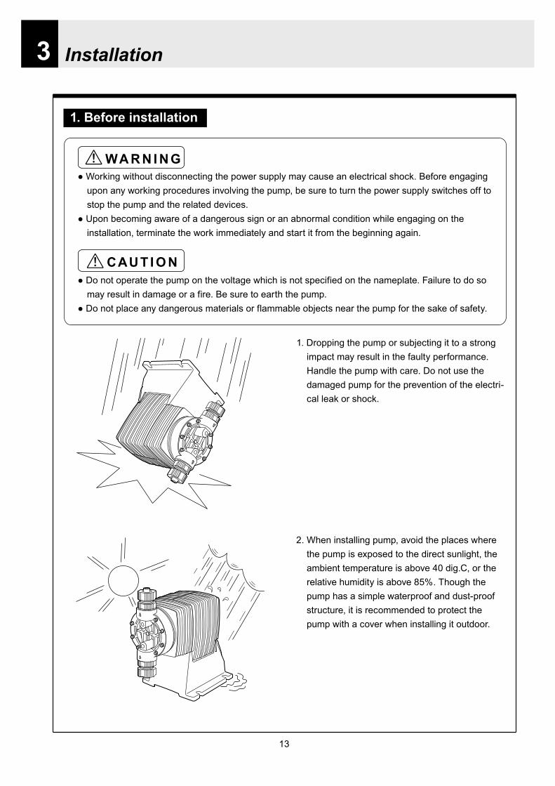
13
Installation
1 Before installation
Working without disconnecting the power supply may cause an electrical shock Before engaging upon any working procedures involving the pump be sure to turn the power supply switches off to stop the pump and the related devices
Upon becoming aware of a dangerous sign or an abnormal condition while engaging on the installation terminate the work immediately and start it from the beginning again
Do not operate the pump on the voltage which is not specified on the nameplate Failure to do so may result in damage or a fire Be sure to earth the pump
Do not place any dangerous materials or flammable objects near the pump for the sake of safety
WARNING
CAUT ION
1 Dropping the pump or subjecting it to a strong impact may result in the faulty performance Handle the pump with care Do not use the damaged pump for the prevention of the electri-cal leak or shock
2 When installing pump avoid the places where the pump is exposed to the direct sunlight the ambient temperature is above 40 digC or the relative humidity is above 85 Though the pump has a simple waterproof and dust-proof structure it is recommended to protect the pump with a cover when installing it outdoor
3
Installation
14
3 Select a level floor and use the four M6 bolts to firmly anchor the pump so as not to allow any vibration If the pump is inclined the discharge amount may decrease considerably
4 Pump should be installed in a well-ventilated place in summer and free from freezing in win-ter
6 Place the pump as close to the suction tank as possible realizing a flooded suction system (It is recommended the pump should be located lower than the suction-side tank)
7 If the pump is used to feed some liquid that gen-erates air bubbles easily (sodium hypochlorite hydrazine solution etc) the system must be positioned in a cool dark place away from direct sunlight If a tank is installed realize a flooded suction system
5 Select the installation site convenient for the future maintenance and inspection
2 Precaution for piping Piping vibrates due to the pulsation from pump Piping should be supported in order to prevent the vibra-
tion Install an air chamber or an accumulator to reduce the pulsation Ask us for further information Be careful not to have hose bend when arranging tubing It is recommended to arrange the short piping as much as possible The longer piping length the more
pressure drops and can exceed the allowable pressure of pump and can cause the over feed phenom-enon
It is recommended an automatic air bleed valve or a pressure relief valve should be installed in order to release the pressure of discharge piping for maintenance
It is recommended to install a relief valve on the discharge side piping that releases pressure automati-cally
Install a pressure gauge on the discharge side piping in order to measure the pressure inside the piping When installing EH-F pump with the flange connections or the union connections be sure to have the
connections on the discharge side fixation on wall pillar or the frame of equipment for the prevention of vibration Make sure that the piping is fixed as well
CAUTIONIncomplete fixation of pump and piping can lead to the damage to these products Significant vibration often results from the incomplete support for the discharge side connection of pump In case the direct support for the flange or union connection can not be secured try to support pump close to the discharge connection as much as possible
15
Installation
Check valve
Air bleedValve
Discharge hose
Pump
Tree way joint
Accumulator
Drain valve
Discharge valve
Back pressure valve
Pump
Suctionvalve
Air bleed valve
Airchamber
Pressure gauge
Relief valve
3 Piping1 Recommended piping drawings
Arrange piping to meet the suction and dis-charge requirement Especially pay attention to piping arrangement in case of handling the slurry which has settling property
Installation
16
Hose
Hose stopper
Fitting spacer
O ring
Fitting nut
Place hose stoppers with R surfaceface to face with fitting spacer
Hose
Hose stopperFitting spacer
O ring
Fitting nut
Fitting
Suction port
Pump head
2 Piping arrangement1 For hose connection first fit a fitting nut and then a
hose stopper and a fitting spacer in the last place If the hose stopper is not fitted properly leakage may occur and suction amount may decrease
The hose end should be secured by a hose stop-per Insert a hose end into a fitting spacer via a fitting nut and a hose stopper Then squash the hose end between the hose stopper and the fit-ting spacer Finally screw the fitting nut in
The hose stopper should be placed with its R surface face to face with the fitting spacer An incomplete hose stopper fixation or a reverse hose stopper placement can lead to leakage or insufficient suction
CAUTIONReverse hose stopper placement can dam-age hose
Fitting nut is made of plastics The fitting nut may break when it is tightened excessively
If attached hose is not long enough prepare a substitute hose such as chloroethene braided hose and polyethylene hose with a suitable bore to the hose fitting spacer
CAUTIONIt is very dangerous to attach the different size hose It may come off
Insert the fitting spacer into hose as deep as possible If the insertion is not enough hose may come off and leakage may result
Be careful not to lose the attached O rings Leakage or suction failure may result without an O ring
2 Hose connection tends to loose if liquid or ambient atmosphere is higher than normal temperature Re-tighten the fitting nut properly after starting opera-tion Be careful not to tighten the nuts too much
3 When fitting the hose again after detaching it for maintenance cut the end of hose off about 10 mm and insert it
17
Installation
4 Check valveEH-F35 45 (VCV6PC) types are attached with a check valve Fit the check valve to piping in the fol-lowing cases
1 The suction side liquid level is higher than the dis-charge side liquid level (Fig A) When injection point is below the liquid level of suction side at atmospheric pressure
2 The suction side pressure is higher than the discharge side pressure (Fig B)
3 The discharge side liquid level is higher than the suction side liquid level but the differential height between both liquid level is 5 m or below (Fig C)
4 The loading pressure of piping resistance and dis-charge head to the pump is under 013 MPa
Suction side Discharge side
Figure A
Figure B
5m
Figure C
To chemical tankor vessel
Remove check valve
3 Piping for bleedingPrior to bleeding disconnect hose and point a hose end at a suction tank or vessel Remove a check valve if it is attached on the discharge side piping
18
Installation
R12
Oslash12
5 Check valve mounting1 Tap the female thread of NPT12 at an injection
point Check valve is provided with the male thread of R12 Cut off the unused portion to fit it on a pip-ing
2 Apply seal tape on the threaded portion of the check valve and screw it in the injection point Pinch the check valve body lightly with a spanner and tighten it for easy mounting
3 When fitting a hose into a check valve with the check valve on main pipe tighten the fitting nut holding the check valve body by hand
4 Cut the end of check valve(empty 12) accordingly when mounting it in a small pipe It is recommended the end of the check valve comes at the centre of pipe bore
It is recommended to mount a check valve via a valve for maintenance Provide NPT12 female thread and screw it in Valve should be resistant to the chemical liquid in use
Valve
Check valve
Check valve body
Apply seal tape
Fitting nut
Pipe
Cut the end nozzle offif it is too long compared topipe bore
6 Flange connection and union connection1 Flange units and union sockets are packed apart from pump body Fit the flange units or the union sockets to
pump body before use Refer to the following figures2 Secure the sealing by fitting O rings to each connection
CAUTIONWhen mounting flange units or union sockets to pump body be careful not to allow O ring to get out of the groove Especially pay attention to the O ring on the groove on suction side
3 Fix the flange units or the union sockets to the pump body by tightening fitting nuts In this case first tighten the fitting nuts by the hand and then re-tighten it by 90 degrees with a spanner
CAUTION
Fitting nut is made of plastics The fitting nut may break when tightened excessively
Flange connection type
19
Instillation
Flange
Flange
Fitting nut
O ring
O ring
Elbow
Pump body
Fitting nut
Drain
Discharge
Air chamber
7 Accumulator and air chamber mountingInstall an accumulator or an air chamber on piping for the prevention of the vibration from the pulsation of pump discharge hose
20
Installation
8 Piping (General notes)1 Keep piping short and less bends Do not make the projections where air can remains
2 Support piping to avoid having the pump subject to the piping weight especially when wet-end mate-rial is made of PVC
3 In case of transferring the slurry which tends to settle do not make U shape on piping A drain plug is required at the lowest portion of piping as well
4 In case of transferring the viscous or toxic liquid or the liquid which tends to settle provide the piping for cleaning for the purpose of maintenance
5 In case of transferring the high temperature or low temperature liquid the telescopic motion of piping from temperature variation should be taken into consideration
6 Select pipe materials based on a through examination of the corrosive resistance and the estimated pressure applied to piping
7 Do not allow any adhesive agent to get in pump when connecting PVC-made pipe on the discharge side piping
8 Clean the inside of piping before installing pump in it
9 A relief valve is required to protect pump and piping Install a relief valve on the discharge piping near the pump
9 Suction piping1 Regarding suction piping a flooded suction system should be realized The bore of suction piping is
recommended to be larger than that of pump suction port
2 Each joint of suction piping needs to be mounted carefully in order to prevent air from coming in Air influx into piping may cause discharge performance failure and instability
10 Discharge piping1 Mount a relief valve on the discharge piping near pump A discharge valve should be mounted beyond
the relief valve
2 The pressure resistance of discharge piping should be higher than the set pressure of relief valve Mount each joint carefully
21
Installation
4 Electrical wiring
1 Power cord connection
Electrical works and the handling of power source must be done by qualified person
Do not operate pump with the wet hand
Make sure that power is not turned on while working on wirng
Do not dismantle electronic circuit
Electronic circuit may be broken Never apply other voltages than a rated voltage
WARNING
CAUT ION
High power equipment
CAUTION Avoid sharing a power source with a high
power equipment This can lead to the fail-ure of the electronic circuit of control unit due to extremely large surge voltage
The noise from an inverter can cause fail-ure
22
Installation
P
Surge absorption element
PNoise cut transformer
CAUTION
2 Wiring procedure
Electronic circuit of control unit may be failed by extremely large surge voltage Do not use the pump near to the high power equipment of 200V or more which may generate large surge voltage If the use of high power equipment is inevitable take either of the following measuresa Install a surge absorption element such
as varister with 2000A or more durability on the power point
b Install a noise cut transformer
CAUTION
Only qualified operatorsservice staff should be in charge of the related electrical arrange-ment and control of the power source Failure to observe this instruction may result in injury to person or damage to assets
Never connect wires while power is turned on otherwise an electrical shock or a short-circuit of controller may result Be sure to turn off power before wiring
Internal circuit is still electrified right after turning off power Take 1 minute or more to start wiring
Do not band a power cable either electrical wires or relay output wires
Earthing wire is equipped with a jumper pin Keep the jumper pin equipped in use
Do not combine the EXT or STOP signal line with a power cord or a power cable Do not com-bine power source line with the EXT or STOP signal line by a concentric cable (5 wires cable or so) Otherwise noise come about through EXT and STOP wires due to the induction effect from power cable and it may results in wrong operation or the failure of pump
Regarding frequent ON-OFF operation it is recommended to stop pump thorough STOP input terminal but not by connecting or disconnecting power source When connecting and discon-necting power cord can not be avoided it should be within 6 times an hour
23
Installation
Procedure to connect the signal cordUse DIN connector of five poles and four polesThe following connectors made by Binder in Germany are recommendedAsk IWAKI for the detail of Binder connector 5 poles 713 series 99-0436-10-05 for input signal 4 poles 715 series 99-0430-15-04 for level sensor
The following connector made by Hirschmann in Germany is recommendedAsk IWAKI for the detail of Hirschmann connector 4 poles GDS307 for output
The following procedures are based on the connector made by Binder and HirschmannIf a similar connector is used the wiring should be made according to the instruction manual of the manufacturer of connector
In case of Binder connector(1) Dismantle the connector and pass the wire through it Outer diameter of the cable should be oslash4-6
Using the different cable in diameter the connector can not be sealed properly
(2) Strip the cable ends and insert wire to the appropriate positions and connect them with screwsThe maximum allowable cross section of the wire is 075mm2
(3) After connecting the wire assemble the connector securely Slightly pull the cord to confirm that the cord connection is secured Perfect sealing can not be obtained unless the cord connection is loose
24
Installation
In case of Hirschmann connector(1) Dismantle the connector and pass the wire through it Insert a minus screw driver into the place shown by
ldquoLIFTrdquo and lift it up Outer diameter of the cable should be 35-6 mm Using the different cable in diam-eter the connector can not be sealed properly
(2) Strip the cable ends and insert wire to the appropriate positions and tighten them with screwsThe maximum allowable cross section of the wire is 075mm2
(3) After connecting wire assemble the connector securely Slightly pull the cord to confirm that the cord connection is secured Perfect sealing can not be obtained unless the cord connection is loose
Terminal position
NA Not Applicable
Connection of level sensorThe controller corresponds to two stage level sensor Connect the pre-alarm signal to Pre-STOP and the alarm signal to STOP When the pre-alarm signal comes in the orange lamp lights but the pump does not stop When a contact type is used connect wires to STOP and COM2 For open collector output level sensor Pay attention to the polarity Pre-Stop and STOP are plus (+) and COM2 is minus (-) (Max charged voltage 5V Current 18mA) For contact output level sensor Use the one designed for electronic circuit and the minimum applicable load of 1mA or less
Connection inside connector 1 STOP 2 Pre-STOP 3 Free 4 COM2
1
2
3
4 CLOSE
ON
PUMP
Level Sensor(STOP)
OPEN
Pulse
COM
+12VDC
NA
ANA(4-20)
Pre-STOP
STOP
COM
NA
OUT
25
Installation
Stop functionStop function is the function to stop the pump by the external signal Connect the wires to STOP and COM2 in the same way as the level sensor connection
CAUTION
Frequent stop and start of pump should be done by using STOP function (ON and OFF of STOP terminal) If you can not use STOP function and are forced to operate pump by turning OFF and ON of power source ON and OFF of power source should be limited to six times an hour
Pulse signal inputPulse signal input is used when the pump runs in the DIV or MULT of EXT modeDIV means dividing and MULT means multiply In case of open collector signal Pay attention to the polarity Pulse is plus (+) and COM1 is minus (-) (Max charged voltage 5V Current 18mA) In case of contact signal Use the one designed for electronic circuit and the minimum applicable load of 1mA or less
Connection inside connector 1 Free 2 Pulse 3 Free 4 12VDC 5 COM
3
2
4
15
Analog signal inputAnalog signal input is used when the pump runs in ANAR or ANAV of EXT modeANAR means analog rigid and ANAV means analog variable
Connection inside connector 1 ANA 2 Free 3 Free 4 Free 5 COM
3
2
4
15
26
Installation
Output signalOUT Photo MOS relay outputStandard is output synchronous with stroke Output is activated synchronous with each pump stroke
Connection inside connector 1 OUT 4 OUT
OUT 1
2
34
Surge voltage The electronic circuit of the control unit may be affected by excessively high surge voltage Do not operate the pump near the high-power elec-trical equipment of 200V or above that generates high surge voltage Under unavoidable circumstances take either of the following measures(1) Use a surge absorbing element (such as a
varistor with the surge resistance of 2000A or more) at the pump power supply connection
(2) Use a noise-cut transformer
Surge absorbing element
Noise-cut transformer
1 Preparation for pump operationBefore pump operation check that
bull Liquid tank is filled enough Supply liquid if it is less than the required levelbull There is no liquid leakage or congestion due to breakagebull Both suction and discharge side valves are openedbull Pump is connected to the predetermined power source correctlybull Electrical wiring is correct and there is no possibility of a short circuit or current leakage
2 BleedingBleeding is a process to eliminate the air inside the suction-side piping Be sure to carry out an air elimi-nation prior to initiating the pump operation after replacing the liquid inside a tank and after a long peri-od of storage Air gushes together with chemical liquid when carrying our bleeding For safety reasons first turn the end of a bleeding hose to a tank or a container
CAUTION
Some liquids may cause skin trouble or affect the quality of mechanical parts Wipe off chemi-cal liquid immediately when they splash on the hand or mechanical parts
27
Operation
1 Pump Operation
WA R N I N G Wear protective clothing
Wear protective clothing such as a protective mask safety gloves or so when handling chemical liquid
Do not operate pump with a discharge-side valve completely closed Operating the pump with the discharge-side valves fully closed may cause the liquid spillage or
the extremely high pressure inside the pump or the discharge-side pipingtubing This could lead to a piping burst Be sure not to operate pump with the discharge-sides valve closed
CAU T I O N A long time dry running (longer than 30 minutes) may cause the pump overheat and it could lead
to the deformation of the pump unit consists of a pump head and valve cases or so or may loosen the pump head fitting and result in liquid leakage
If the hex socket cap bolts on a pump head are loosened liquid leakage may resultBe sure to fasten all the 6 or 8 hex socket cap bolts tightly before starting the initial pump opera-tion And periodically check the looseness of the bolts on the pump head and retight the bolts as necessary
bull Tightening torque255NbullmTighten all the bolts diagonally applying equal tightness
If electric wiring gets wet due to accidental liquid spillage fire or electrical shock may occur Never get it wet When the electric wiring gets wet turn off power and wipe the liquid away
A frequent ON-OFF operation should be conducted by using STOP function(ON - OFF signals to STOP terminal) In case the STOP function is not available for the ON-OFF operation the ON - OFF operation by turning onoff power should be limited to six times an hour
4
28
3 Procedure for bleeding
Check valve should be removed
To tank or drain pan
100
75
50
25
0 25 50 75 100
(Fixed stroke length)
Stroke length adjustment
240spm
180spm
120spm
Flow
rate
Operation
[1] Extend the tube connected to the discharge-side fitting nut of pump to a chemical tank or a drain pan Then start pump operationbull Remove a check valve if it is installed on dis-
charge-side
[2] Operate the pump for about 10 minutes to eliminate air completely
[3] When the air in pump head is completely eliminated and liquid is replaced return the discharge-side tube to the regular tubing position
[4] Finally make sure there is no leakage in any section
4 Discharge capacity adjustmentDischarge capacity can be adjusted by both the stroke length adjustment and the stroke rate adjust-ment but basically adjust it via the stroke rate adjustment Stroke length adjustment is an auxiliary way to cover the range where the stroke rate adjustment can not reachPay attention to the following for correct procedure
Stroke rate adjustment(1) For some liquids which diffuses gas such as sodium hypochlorite and hydrazine solution adjust discharge capac-
ity by means of the stroke rate adjustment with the stroke length about 100 Gas lock may occur if the stroke length is set to short
(2) When the back pressure on discharge side is high adjust discharge capacity by the stroke rate adjustment with the stroke length about 100
(3) In case reaction is greatly influenced depending on the discharge capacity per pump shot in the application of neutralization or titration adjust discharge capacity by the stroke rate adjustment with the shortened stroke length and reduce the discharge capacity per shot
1 Discharge capacity adjustment procedureAppropriate stroke length and stroke rate are decided on the pump operating condition and liquid characteristics Following ways are recommended for proper calibration
(1) Set stroke length at 100 and roughly adjust discharge capacity by adjusting stroke rate
(2) Measure discharge capacity(3) If the measured capacity is below the wanted value
increase the stroke rate and measure again the dis-charge capacity
(4) Adjust stroke length for the fine adjustment of discharge capacity(5) Determine a discharge capacity at the last and confirm the wanted capacity is discharged
CAUTION
29
100
75
50
25
0 60 120 180 240spm
Fixed stroke length
Stroke rate adjustment
Flow
rate
Screw driverOPEN
LOCK
100
75
50
25
0 25 50 75 100
Fixed stroke rate
Flow
rate
Stroke length adjustment
Operation
2 Stroke rate adjustmentStroke rate is adjusted by the key operations of control unit Control the plunger stroke rate per minute from 1 to 240 spm via control unit
3 Stroke length adjustmentStroke length adjustment knob is locked with a screw Loosen the screw before adjustment and lock it afterwards
(1) Turn on pump and adjust the discharge capacity by turning the stroke length adjusting knob while pump is running
(2) The left graph shows the relation between stroke length and discharge capacity The maximum dis-charge capacity is shown on the name plate
bull The usage between 40 and 100 is practi-cal
Do not turn the stroke length adjusting knob when pump stops
CAUTIONBe sure to tighten the screw on the adjust-ment knob after an adjustment The knob may rotate unintentionally due to a loose fixation This may result in the fluctuation in a discharge rate
30
Mode ParameterDefault value
Setting range Step
Manual operation Stroke speed 240 1-240DIV setting Dividing ratio frasl 1 1-9999
MULT setting Multiply ratio times1 times1-9999ANA R setting 4-20 4-20 20-4 0-20 20-0
ANA V setting
P1 amperage 40 00-200P1 stroke speed 0 0-240P2 amperage 200 00-200P2 stroke speed 240 0-240
User setting
EXT operation ANA V DIV MULT ANA R ANA V
Anti-chatteringMECH MECH ELECST05 ST05 ST20 ST50FT01 FT02 FT04
Buffer memory MEM-N MEM-N MEM-Y
111-
011
011
2 Control unit operationEH-F type pump is controlled by means of setting or changing the setting values of the controller Control functions are various at each operation mode Read this section carefully before operation
Default parameter values
5 Full operationPut pump in use after bleeding and adjusting discharge capacityPump runs in manual operation or in accordance with the setting of control unit
6 Manual operationStarting pump After turning on power ON lamp (Green) appears and display shows WAIT mode For
the first time to turn on power MAN lamp appears and pump starts after pushing STARTSTOP key once
Stop pump Push STARTSTOP key to turn off MAN lamp and stop pump Pump starts and stops every time STARTSTOP key is pressed
7 EXT operationRefer to the next section of 2 Control unit operation
8 Shout down When pump will not in use for a long time (one month or more)
Run pump with clean water about 30 minutes in order to clean the wet-end parts and the inside of pip-ing before storage
When re-starting pump after a long time storage If pump dose not suck up liquid clean valve sets and remove the sticking foreign matters Carry out an air elimination and adjust discharge capacity when air stays inside pump head Refer to page 28 3 Procedure for bleeding
Operation
---
-
31
AN
A V
(Ana
log
var
iabl
e)
DIV
(Pul
se d
ivid
ing)
MU
LT(P
ulse
mul
tiply
)A
NA
R(A
nalo
g ri
gid)
SE
TS
ET
Use
r mod
e
EX
T m
ode
sele
ctio
n
EX
T
EX
TE
XT
EX
TE
XT
EX
T EX
T
EX
T
EX
T
EX
T
EX
T
EX
T
EX
T
EX
T
EX
T
EX
T
EX
T
EX
T
3 sec
onds
or m
ore
Wai
t mod
e
Set
ting
of fi
xatio
n pa
ttern
EX
T m
ode
Man
ual o
pera
tion
Set
ting
of s
troke
num
ber
AN
A R
(Ana
log
rigi
d)M
ULT
(Pul
se m
ultip
ly)
DIV
(Pul
se
div
idin
g)
AN
A V
(Ana
log
var
iabl
e)
anti-
chat
terin
gse
tting
dis
play
Setti
ng o
f div
idin
g ra
tioS
ettin
g of
cou
nt n
umbe
r
Curre
nt va
lue of
P1
Stro
ke nu
mbe
r of P
1
Curre
nt va
lue
of P
2
Stro
ke nu
mbe
r of P
2
EX
T O
pera
tion
Dis
play
EX
T se
tting
mod
e
Buf
fer m
emor
yse
tting
dis
play
Pow
er O
N
spm
MA
Nsp
m
spm
DIV
DIV
SE
TS
ET
MU
LT
MU
LTsp
mA
NA
V
spm
AN
AR
AN
AR
SE
Tm
AS
ET
mA
spm
AN
A
V
P1
mA
SE
T
spm
AN
A
V
P1
AN
AR
SE
Tm
A
AN
AR
SE
Tm
AS
ET
AN
A
V
P 2
SE
T
spm
AN
A
V
P 2
AN
AR
SE
Tm
A
AN
A
V
SE
TS
ET
SE
T
SE
T
SE
T
SE
T
SE
T
SE
T
SE
T
SE
T
SE
TS
ET
1 Overview Operating Scheme
Operation
1 means automatic transfer WAIT mode is selected when the power is switched on for the first time On and after the initial power activation pump restores the previous status right before the power is switched off
2 Regarding MANUAL mode pump starts operation by pushing STARTSTOP key at WAIT modePushing STARTSTOP key again the pump stops and returns to WAIT mode
3 Regarding EXT operation pushing EXT key at WAIT mode the pump moves to EXT mode and starts operationPushing STARTSTOP key stops the operation and returns the pump to WAIT mode
4 The change of each setting of EXT operation is accessible by pushing EXT key at EXT mode Pushing EXT key after the setting pump starts in EXT operation according to the changed setting
5 Pushing EXT key for 3 seconds at WAIT mode pump moves to USER mode At USER mode the EXT mode selection and the detailed setting such as the setting of buffer memory or so can be obtained
For details refer to each section of 2 Pump operation
2 Pump operation1 Operation of controller
Before turning on power confirm the specified power source on the nameplate
CAUTION
Connecting any other powers than the one shown on nameplate to pump is strictly prohibitedIt could lead to pump trouble or failure
Operation
32
1 Turning on powerDisplay shows WAIT mode when pump is turned on for the first time After the initial power activation the pump restores the previous mode right before the power was turned off last time If power is turned off at any setting modes WAIT mode appears at the next power activation
Stroke speed setting value is shown on display at WAIT mode ON lamp lights (Green)
EXT
EH-F ControllerSTARTSTOP
ON STOP
spm
33
2 Manual operation(1) Stroke speed can be adjusted by and
keys The figure changes quickly when either or key is depressed The picture below
shows the stroke speed is set to 160 spm
EXT
EH-F ControllerSTARTSTOP
ON STOP
spm
EXT
EH-F ControllerSTARTSTOP
ON STOP
MAN spm
EXT
EH-F ControllerSTARTSTOP
ON STOP
spm
(2) Push STARTSTOP key once to start the pump operation MAN indication appears and ON lamp blinks synchronously with each stroke
(3) MAN indication disappears and ON lamp stops blinking as STARTSTOP key is pushed again Pump enters WAIT mode
Operation
Operation
34
EXT
EH-F ControllerSTARTSTOP
ON STOP
ANA V
P1 SET mA
EXT
EH-F ControllerSTARTSTOP
ON STOP
P1 SET
ANA V spm
EXT
EH-F ControllerSTARTSTOP
ON STOP
spm
EXT
EH-F ControllerSTARTSTOP
ON STOP
ANA V spm
(4) Set the current value at P1 Figure increases or decreases as or key is pushed The pic-ture below shows 80 mA is set to point 1
EXT
EH-F ControllerSTARTSTOP
ON STOP
ANA V
P1 SET mA
(5) Pushing EXT key once spm appears on the display while mA disappears The picture below shows the number of strokes at P1
EXT
EH-F ControllerSTARTSTOP
ON STOP
P1 SET
ANA V spm
3 EXT operation (ANA V mode)(1) Push STARTSTOP key to move to WAIT mode
if pump is in another mode Go to next step if pump is in WAIT mode
(2) ANAV indication appears and pump enters an EXT mode as EXT key is pushed once Pump starts operation in accordance with current sig-nals and various settings ON lamp blinks at each pumping during operation Pump is con-trolled via the EXT mode which was select-ed at USER mode The initial setting of EXT mode is ANA V mode Select a preferable EXT mode in USER mode The picture below shows ANA V mode (The spm on the display changes according to input signals)
(3) Push EXT key once when pump is running in ANA V mode Display indicates the setting display of ANA V mode spm indication dis-appears and P1 SET and mA indications appear on the screen
(6) Set the number of strokes at P1 Figure increasesdecreases as key is pushed Picture below shows 10 spm is set for point 1
Operation
35
(7) Push EXT key to move to the setting display of the current value at P2 P1 and spm disap-pear and P2 and mA appears instead
EXT
EH-F ControllerSTARTSTOP
ON STOP
ANA V
P 2 SET mA
EXT
EH-F ControllerSTARTSTOP
ON STOP
ANA V
P 2 SET mA
EXT
EH-F ControllerSTARTSTOP
ON STOP
P 2 SET
ANA V spm
(11) Push EXT key to return to EXT mode Pump starts to run in ANA V mode on the setting of (4) through (10) ON lamp starts to blink at each pumping
EXT
EH-F ControllerSTARTSTOP
STOPON
ANA V spm
EXT
EH-F ControllerSTARTSTOP
ON STOP
P 2 SET
ANA V spm
EXT
EH-F ControllerSTARTSTOP
ON STOP
spm
(8) Set the current value of P2 by pushing and keys Picture below shows 180 mA is set to
point2
(9) Pushing EXT key once spm appears on the display while mA disappears The picture below shows the number of strokes at P2
(10) Set the number of strokes at P2 by pushing and keys Picture below shows 200
spm is set to point 2
(12) Pushing STARTSTOP key pump enters WAIT mode and pump stops ON lamp stops blink-ing and ANAV indication disappears
CAUTIONWhen the setting of the buffer memory is OFF keep the number of strokes in the dividing operation 240 spm or below The input signals to operate the pump over 240 spm can cause an unstable pump operationWhen the setting of the buffer memory is ON the pump operates for all the input pulse signalsPump keeps operating after all the signals are stopped in this case Be careful when setting of buffer memory
Operation
36
EXT
EH-F ControllerSTARTSTOP
ON STOP
DIV
SET
EXT
EH-F ControllerSTARTSTOP
ON STOP
DIV
SET
EXT
EH-F ControllerSTARTSTOP
STOPON
DIV spm
EXT
EH-F ControllerSTARTSTOP
ON STOP
spm
(2) Pushing EXT key DIV appears and pump starts operation in the ratio of input pulse sig-nals a pumping ON lamp blinks synchronous-ly at each pumping The initial setting of EXT selection is ANA V mode Change mode to DIV mode via USER mode Refer to P 40 for detail information
(3) Push EXT key while pump is operating in DIV mode Pump stop running and SET indication appears on the DIV setting display in stead of spm indication
(4) Enter a dividing ratioFigure increasesdecreases when key is pushed The picture below shows 10 is set
4 EXT operation (DIV mode)
(1) Push STARTSTOP key to move to WAIT mode if pump is in another mode Go to next step if pump is in WAIT mode
CAUTIONOn condition the setting of buffer memory is OFF do not input any pulse signals during the pumping motions for a input pulse signal in the multiply operation These input pulse signals are cancelledWhen the setting of buffer memory is ON pump operates for all the input pulse signals
Operation
37
EXT
EH-F ControllerSTARTSTOP
ON STOP
spm
EXT
EH-F ControllerSTARTSTOP
STOPON
DIV spm
EXT
EH-F ControllerSTARTSTOP
ON STOP
spm
EXT
EH-F ControllerSTARTSTOP
ON STOP
MULT
(5) Push EXT key to return to EXT operating mode Pump starts to run on the setting at item (4) ON lamp blinks synchronously at each pumping
(6) Pushing STARTSTOP key pump enters WAIT mode and pump stopsDIV indication disappears and ON lamp stops blinking
5 EXT operation (MULT mode)
(2) MULT indication appears and pump starts running in an EXT operation mode in the ratio of an input pulse signal pumpings as press-ing EXT key ON lamp blinks at each pump-ing Display shows the rest of the number of strokes In MULT mode the number of strokes is equal to the setting value in manual opera-tionThe initial setting of the EXT mode selection is ANA V mode which is the operation in pro-portion to current First select MULT mode via USER mode Refer to P 40 for detail informa-tion
(1) Push STARTSTOP key to move to WAIT mode if pump is in another mode Go to next step if pump is in WAIT mode
Operation
38
EXT
EH-F ControllerSTARTSTOP
ON STOP
spmEXT
EH-F ControllerSTARTSTOP
ON STOP
ANAR spm
EXT
EH-F ControllerSTARTSTOP
ON STOP
MULT
SET
EXT
EH-F ControllerSTARTSTOP
ON STOP
MULT
EXT
EH-F ControllerSTARTSTOP
ON STOP
spm
EXT
EH-F ControllerSTARTSTOP
ON STOP
MULT
SET
(5) Push EXT key to return to MULT mode(3) Pushing EXT key when pump is running in the multiply operation calls the setting display of MULT mode and SET indication appearsPump stops running and ON lamp stop blinking
(4) Enter the number of pumpings per input signalFigure increasesdecreases when key is pushed The picture below shows the pump-ing number is set to 1800 times per an input signal
6 EXT operation (ANA R mode)(1) Push STARTSTOP key to move to WAIT mode
if it is in another mode Go to next step if it is in WAIT mode
(6) Pushing STARTSTOP key recalls WAIT mode and pump stops spm indication appears in stead of MULT indication
(2) Pushing EXT key ANAR appears and pump starts running in the ratio of an input pulse sig-nal pumpings ON lamp blinks at each pump-ing The initial setting of the EXT mode selec-tion is ANA V mode which is the operation in proportion to current is selected First select ANA R mode in USER mode Refer to P 40 for more information
Operation
39
EXT
EH-F ControllerSTARTSTOP
ON STOP
ANAR
SET mA
EXT
EH-F ControllerSTARTSTOP
ON STOP
ANAR spm
EXT
EH-F ControllerSTARTSTOP
ON STOP
ANAR
SET mA
EXT
EH-F ControllerSTARTSTOP
ON STOP
spm
(4) Figure increasesdecreases when key is pushed The picture below is when it is set to 0-240 spm for 20-4 mA
(5) Push EXT key to return to EXT mode Pump starts to run on the setting at item (4) ON lamp blinks synchronously at each pumping
(6) When pushing STARTSTOP key pump enters WAIT mode and stops running ON lamp stops blinking and ANAR disappears
(3) Pushing EXT key when pump is running in the multiply operation calls the setting display of ANAR mode and SET and mA indications appear while spm disappears Pump stops running and ON lamp stops blinking
Operation
40
EXT
EH-F ControllerSTARTSTOP
ON STOP
ANA V
(5) Push EXT key to confirm the desired EXT mode Pump displays the EXT mode selection The picture below shows DIV appears to indi-cate DIV mode is selected
EXT
EH-F ControllerSTARTSTOP
ON STOP
DIV
EXT
EH-F ControllerSTARTSTOP
ON STOP
SET
EXT
EH-F ControllerSTARTSTOP
ON STOP
spm
EXT
EH-F ControllerSTARTSTOP
ON STOP
spm
EXT
EH-F ControllerSTARTSTOP
ON STOP
SET
7 USER settingThe setting of each function is changed in USER mode Have the pump entering WAIT mode in order to move to USER mode OUT (Output) is synchronous with spm and it can not be changed
7-1 EXT mode selection Any one of DIV (pulse dividing) MULT (pulse multiply) ANAR (analog rigid) or ANAV (analog vari-able) can be active in EXT mode The initial mode when shipped from factory is ANAV
(1) Push STARTSTOP key to move to WAIT mode if it is in another mode If it is in WAIT mode go to next step
(2) Press EXT key for more than 3 seconds to move to USER mode The picture below shows pump enters the EXT mode selection
(3) Pushing EXT key SET appears and display shows the mode currently set Picture below shows ANA V mode is selected
(4) Push or key to select a desired EXT mode The picture below shows DIV mode is selected
(6) Push STARTSTOP key to move to WAIT mode spm appears while DIV goes out
Operation
41
EXT
EH-F ControllerSTARTSTOP
ON STOP
spm
EXT
EH-F ControllerSTARTSTOP
ON STOP
ANA V
EXT
EH-F ControllerSTARTSTOP
ON STOP
SET
(3) Push key once
EXT
EH-F ControllerSTARTSTOP
ON STOP
(4) Push key again to move to the anti-chatter-ing setting display
EXT
EH-F ControllerSTARTSTOP
ON STOP
(5) Pushing EXT key display shows the mode cur-rently set and SET appears on it The picture below shows when MECH is selected
EXT
EH-F ControllerSTARTSTOP
ON STOP
SET
7-2 Setting of anti-chattering Anti-chattering function is settable against the incoming pulses during the DIV or MULT operation For the long chattering of mechanical contact such as relay set a large figure via MECH For the high speed (high frequency) chattering of the semi-conductor type contact such as transistor set a small figure via ELEC ST05 of MECH is initial setting
(6) Select MECH by or key for a mechani-cal contact And select ELEC for a semi-conductor contact The picture below shows ELEC is selected
(1) Push STARTSTOP key to move to WAIT mode if it is in another mode If it is in WAIT mode go to next step
(2) Press EXT key for more than 3 seconds to move to USER mode The picture below shows pump enters the EXT mode selection
Operation
42
EXT
EH-F ControllerSTARTSTOP
ON STOP
SET
(7) Push EXT key to display the current set state The picture below shows FT01 is selected
EXT
EH-F ControllerSTARTSTOP
ON STOP
SET EXT
EH-F ControllerSTARTSTOP
ON STOP
EXT
EH-F ControllerSTARTSTOP
ON STOP
spm
7-3 Setting of buffer memoryIn case pump operation can not catch up with the input pulse signals in DIV or MULT operation exces-sive pulse signals can be put in memory up to 65535 pulses However the excessive pulses can not be restored if once power is off or mode is changed
EXT
EH-F ControllerSTARTSTOP
ON STOP
spm
(2) Press EXT key for 3 seconds or more to move to USER mode The picture below shows the EXT mode selection display
EXT
EH-F ControllerSTARTSTOP
ON STOP
ANA V
(8) Set a large figure for the long chattering by or key and set a small figure for high speed (high frequency) chattering The picture below shows FT04 is selected
(9) Push EXT key to return to the anti-chattering setting display SET indication disappears
(10) Push STARTSTOP key to return to wait mode spm indication appears
(1) Push STARTSTOP key to move to WAIT mode if it is in another mode If it is in WAIT mode go to next
Operation
43
(3) Push key once
EXT
EH-F ControllerSTARTSTOP
ON STOP
(7) Push or key in order to set buffer memo-ry to ON or OFF Select MEM-Y to set it ON Select MEM-N for OFF setting The picture below shows when ON is set
EXT
EH-F ControllerSTARTSTOP
ON STOP
SET
(4) Push key once again
EXT
EH-F ControllerSTARTSTOP
ON STOP
(8) Push EXT key to return to the buffer memory setting display SET indication disappears
EXT
EH-F ControllerSTARTSTOP
ON STOP
(9) Push STARTSTOP key to return to WAIT mode spm indication appears
EXT
EH-F ControllerSTARTSTOP
ON STOP
spm
(5) Push key once again and the buffer memory setting display is shown
EXT
EH-F ControllerSTARTSTOP
ON STOP
(6) Push EXT key in order to display the current set state SET indication appears The picture below shows the buffer memory is set to OFF
EXT
EH-F ControllerSTARTSTOP
ON STOP
SET
Operation
44
8 Bleeding amp self-primingAt WAIT mode Manual operating mode and EXT operating mode pump operates at max speed tak-ing priority over any functions when both and keys are pushed at once Pump runs at max speed only when both keys are depressed Pump state returns to the previous mode once either or key is released Pressing and keys for 10 seconds keeps pump running at maximum speed In this state this fixation is released when pushing either or key once and pump returns to the previous mode
(1) When pump is running in ANAV mode
EXT
EH-F ControllerSTARTSTOP
ON STOP
ANA V spm
(2) Pump start to run at full speed when and keys are pressed at once Display shows
PRIME If either or key is released pump returns to the previous mode In this case pump returns to ANAV mode
EXT
EH-F ControllerSTARTSTOP
ON STOP
ANA V
(3) Pressing both and keys simultaneously for 10 seconds or more pump continues to run at full speed even if both keys are released In this case indication appearsPush either or key to release this state indication disappears and pump returns to the previous mode In this case pump returns to ANAV mode
EXT
EH-F ControllerSTARTSTOP
ON STOP
ANA V
Operation
45
10 Error display and release(1) In case Input signals fall to 4 mA or below while
4-20 or 20-4 is set to ANA R mode pump stops with DISCN blinking and Err on dis-play
(2) This error state can be released by push-ing STARTSTOP key and pumps enters wait mode In this case check the wiring and input signals
EXT
EH-F ControllerSTARTSTOP
ON STOP
ANAR
Err
spm
EXT
EH-F ControllerSTARTSTOP
ON STOP
spm
9 Key lockKey lock function is to prevent pump from being operated by some other person than user If STARTSTOP key is pressed for five seconds or more when pump is running or stops all key operations become ineffective with LOCK indication on display This function can be released by pressing STARTSTOP key for 5 seconds while LOCK lights
EXT
EH-F ControllerSTARTSTOP
ON STOP
MAN spm
LOCK
46
Do not conduct a maintenance work with the wet hands It can cause an electric shock
Before dismantling pump be sure to turn off power and check the pump is not electrified Do not
start a dismantlement work after stopping the pump by pushing the STARTSTOP key only Put up
the sign of ldquoMaintenance work is in progressrdquo in order to prevent a pump switch from turning on
unintentionally during the work Release the pressure of discharge piping and drain the liquid from
the wet end parts And then clean the inside of pump head
Wear protective clothing such as a protective mask globes goggles and chemical-proof wear
according to the handled chemical liquid during the work
WARNING
5 Maintenance
1 Trouble shootingTrouble Cause Troubleshooting
Pump dose not start Faulty wiring or disconnection in wiring Voltage is too low Failure in the electronic circuit of control unit
Pump dose not suck liquidDischarge amount is low
Air suction from suction piping Valve gasket is not installed Valve set assembling direction is wrong Pump is air-locked Pump stroke length is too short Suction-sidedischarge-side valve is clogged with
foreign matter Adhesion of valve onto valve seat
Discharge amount fluctuates
Liquid leaks
Key operation is ineffective Key is locked Release key lock
Pump doesnt run
Pump is in waiting mode Signals are not coming for EXT operation Pump is in EXT setting mode Pump is suspended with STOP
Move to operation mode Check wiring and correct the wrong part Move to EXT operating mode Release STOP function
Abnormal noise
Suction-sidedischarge-side valve is clogged with foreign matters
The sound absorption gasket is worn out Bearing is worn out Spring is damaged
Piping vibrates due to pulsation Bearing is worn out Spring is damaged
Install a accumulator or an air chamber The end of pump life span The end of pump life span
Suction-sidedischarge-side valve is clogged with foreign matters
Air is trapped in pump Overfeeding Diaphragm is damaged
Fittings are not tightly closed Pump head is not tightened Diaphragm is damaged O ring and valve gasket are not installed O ring is damaged
Correct wiring Inspect power source and provide measurement Replace the whole unit
Arrange piping again Install valve gasket Reassemble valve set Carry out air elimination Drive pump with 100 stroke length to prime liquid Then
reset stroke length Disassemble inspect and clean Disassemble inspect and clean
Tighten fittings Tighten pump head Replace diaphragm Install O ring and valve gasket Replace O ring
Disassemble inspect and clean
Carry out air elimination Install a check valve or a back pressure valve Replace diaphragm
Disassemble inspect and clean
The end of pump life span The end of pump life span The end of pump life span
Abnormal vibration
Input pulse can not be read Signals are not coming Anti-chattering setting is not proper
Check wiring and correct the wrong part Change the setting properly
Analog signal input can not be read
Wrong wiring Signals are over acceptable loaded resistance
Check wiring and correct wrong part The load resistance is 200Ω Use some devise which can
accept the load resistance
47
CAUTION Check periodically whether the bolts fixing pump head are tightened Tighten them as needed
The bolts fixing pump head may loosen in operation Tightening torque 255Nbullm
Maintenance
3
bull Tighten joint where leakage has occurredbull The excessive air bubbles in the discharged liquid mean air suc-
tion has been caused in system Examine the piping and tighten joint on where leaks
Is there liquid leakage or air suction at any joints on pump or piping
2 Maintenance and inspection
1 Daily inspectionPay attention to the following points during pump operation Stop pump immediately upon detecting abnormality and take measures according to the item Troubleshooting When wear parts come to the life time replace them by new ones
No
1
2
Check Point Description
Does pump lift liquid normally
bull Is liquid normally fedbull Is suction pressuredischarge pressure at normal levelbull Has liquid undergone quality change crystallization or solidifica-
tion
Abnormal noise or vibrationbull Abnormal noise or vibration may happen from the abnormal func-
tioning of pump
EXT setting can not be stored
After EXT setting STARTSTOP key is pushed for EXT by mistake
Push EXT key to operate pump in EXT mode
ldquoPRIME is kept indicated and other operations are inac-cessible
Self-priming function is active Push either or key to release the function
Analog signal input can not be read and DISCN indication appears
Wrong wiring or disconnection Check wiring and correct the wrong part Refer to page 45
for how to release an error indication
Trouble Cause Troubleshooting
48
Maintenance
2 Wear partsWear parts should be replaced in proper period for a long period of pump operation It is recommended that follow-ing parts are always ready for the replacementVC V6 PC P6 types
Parts Qty Life span
Pum
p he
ad
Valve set
EH-F35 EH-F45 EH-F55middot70
2sets
8000hours
Diaphragm 1
Refer to exploded view
Bac
k pr
essu
re v
alve
1
2
Che
ck v
alve
7 6 1
8 11 1
Diaphragm seat 1
O ring
Poppet check valve (With check gasket)
Check valve spring Spacer
Diaphragm
O ring
Note Durability of wear parts depend on the pumped liquid temperature and pressure Time to be replaced mentioned as above is the estimation obtained by continuous pump-ing of clean water at ambient temperature
8000hours
4000hours
49
3 Dismantlement and assembly
Getting wet with or coming in contact with chemicals and toxic liquid is harmful Wear protective clothing such as a protective mask globes goggles and chemical-proof wear during the work
Risk of electrical shock Be sure to turn off power and confirm that pump and devices are not electrified before the work
Release the pressure inside pump and a discharge hose by opening an air bleed valve on piping prior to loosening the piping connections or the dismantlement of pump Dismantlement with the pressure inside pump could lead to liquid spillage
Be careful not to touch residual liquid when dismantling pump Some liquids are harmful for skin or component parts Wipe off liquid when the hand or the component parts come in contact with liquid
WARNING
CAUT ION
Hose
Hose stopperFitting spacer
O ring
Fitting nut
Fitting
Pumphead
Remove the fittingwith a spanner
1 Valve set replacement Dismantlement1 Loosen a fitting nut and remove the hose con-
nected to pump head Pay attention to the liquid dripping
2 Loosen a fitting with a spanner to remove it Then detach the valve set from pump head
Maintenance
50
AssemblyAssembly procedure is in reverse order to disas-sembly Pay attention to the following when assembling valve set DispositionInsertion direction of valve set The wrong dispositioninsertion direction of valve
set component can lead to leakage and less dis-charge amount
O ring is fitted properly1 Discharge side valve set mounting
Put valve set in pump head and screw a fitting into a pump head by hand and then re-tighten it by 14 turns with a spanner
2 Suction side valve set mountingPut valve set in connection port and screw the fitting into pump head by hand and then re-tighten it by 14 turns with spanner
Note Pay attention to the mounting direction of the spacer fitted to EH-F45(VC V6 PC)Make sure the cut portion on the spacer of suction side should be downward the one of discharge side should be upward
Suction side
Discharge side
O ringValve gasket
Valve gasket
Valve gasket
Valve guideValveValve seatSpacer
O ring
Valve gasketValve guideValveValve seat
Spacer
1714
11
1312
11
1312
17
17
14
14
14
11
31
1312
31
17
14
11
1312
12
13
11
14
EH-F35
EH-F45
EH-F5570
Suct
ion
side
Dis
char
ge s
ide
For b
oth
suct
ion
and
disc
harg
e si
deFo
r bot
h su
ctio
nan
d di
scha
rge
side
VC V6 PC P6 Type
Maintenance
51
Pay attention not to lose diaphragm spacer and to apply the correct number of diaphragm spacers 0 to several pieces of diaphragm spacers are put between retainer and plunger to adjust the position of diaphragm The number of spacers mounted depends on the pump model There are the models which do not have spacers
Maintenance
2 Diaphragm replacement Dismantlement1 Set stroke length to 0 by adjusting stroke length
adjustment knob
2 Remove the pump head from the pump body by loos-ening hex socket cap bolts
3 Rotate a diaphragm anti-clockwise to remove it from a plunger pin The diaphragm is screwed into the plunger pin
AssemblyAssembly is done in reverse order to disassembly Follow the steps below1 Make sure the stroke length of pump is set to 0
prior to an assembly Operate pump to set the stroke length to 0 and
stop it Then turn off power
2 Fit a rear diaphragm seat a retainer and a diaphragm spacer into new diaphragm via the threaded pin and screw the diaphragm into the plunger pin
Fit the concave side of retainer into the convex side of diaphragm Pay attention the retainer dose not come off
3 Set the stroke length to 100 Operate pump to set the stroke length to 100
and stop it Then turn off power4 Install a pump head to a pump body by tightening
the hex sock cap bolts equally Tightening torque is 255Nbullm
52
4 Accessories1 Connection port bore bull Check valve bull Back pressure valve
Note1 Check valves and back pressure valves are options2 Regarding the connection of the discharge side of back pressure valve
NPT38 and NPT12 taper pipe thread is used for BV-N-CR
Pump type Connection port bore Check valve Back pressure valve
EH-F35VC empty38timesempty12 hose CA-3VCH-C6 ndash
empty38timesempty12 hose CA-3VEH-C6 ndashempty38timesempty12 hose CA-3VH-C6 ndashempty38timesempty12 hose CA-3VCH-C6 ndashempty38timesempty12 hose CA-3VEH-C6 ndashempty38timesempty12 hose CA-3VH-C6 ndash
V6
empty38timesempty12 hose ndash BV-3NV-C6Rempty38timesempty12 hose ndash BV-3NE-C6Rempty38timesempty12 hose ndash BV-3NPV-C6Rempty58timesempty34 hose ndash BV-3NV-C7Rempty58timesempty34 hose ndash BV-3NE-C7Rempty58timesempty34 hose ndash BV-3NPV-C7R
PC
EH-F45VCV6PC
EH-F55VCV6PC
EH-F70VCV6PC
Maintenance
53
Maintenance
5 Exploded view
1 General view The extent of dismantlement is within the following exploded view
Diaphragm spacer
Retainer
(Back up retainer)55 bull 70 types
Pump body
Valve set
Valve set
Pump head
Diaphragm
Rear diaphragm sheet
54
2 Pump head (Hose connection type)
EH-F45 type EH-F35 type
4
28
2930
3
1114
131211
131217
1897
1
17
111312111312
3
3029
28
4
1920
1920 21
17
111312
31
3
3029
28
4
131217
189
7
11
3114
14
4
282930
3
1
21
1515
EH-F55 type
4
28
2930
3
11
131217
18
9
7
10
1
1920 21
17
111312
3
30
29
28
4
EH-F70 type
4
28
2930
3
14
11131217
18
9
7
10
1
1920 21 17
111312
3
30
29
28
4
15 15
14
1414
14
14 14
Note1 The back up retainer of No10 is only for EH-F55 bull 70 typesNote2 The figure inside ( ) in the above table is for EH-F45 bull 55 bull 70 typesNote3 The number of the diaphragm spacers (No18) is not constant None or a few spacers is inserted at
each diaphragmNote4 The figure inside ( ) in the above table is for EH-F70Note5 EH-F35 bull 55 bull 70 (VC V6 PC ) types require 2 valve gaskets and EH-F45 (VC V6 PC) types
require 4 of themNote6 The spacer on No31 is for EH-F45 type only
No Name Qty1 Pump head 13 Fitting 24 Fitting nut 27 Diaphragm 19 Retainer 110 Back up retainer 1 Note111 Valve guide 4 (2) Note212 Valve seat13 Valve14 Valve gasket
No Name Qty
17 O ring 218 Diaphragm spacer 1 Note319 Hex socket head bolt 6 (8) Note420 Spring washer21 Plain washer28 Hose stopper 229 Fitting spacer 230 O ring 231 Spacer 2 Note6
15 Rear diaphragm seat 1
2 (4) Note54 (2) Note24 (2) Note2
6 (8) Note46 (8) Note4
Maintenance
55
Maintenance
3 Pump head (Flange connection type) EH-F55 type
30
3
11
131217
18
9
7
10
1
1920 21
17
11
1312
3
30
EH-F70 type
15
EH-F45 type EH-F35 type
30
3
11131211
131217
1897
1
17
11131211
1312
3
30
1920
1920 21
17
111312
31
3
131217
189
7
11
31
30
3
1
30
21
1515
30
3
11131217
18
9
7
10
1
1920 21 17
11
1312
3
30
15
32
33
33
32
4
32
433
43332
32
334
43332
32
33
32
334
44
1414
14 14 14
1414
14
14 14
NoNo Name Qty1 Pump head 13 Fitting 24 Fitting nut 27 Diaphragm 19 Retainer 110 Back up retainer 1 Note111 Valve guide 4(2)Note212 Valve seat 4(2)Note213 Valve 4(2)Note214 Valve gasket 2(4)Note5
Name Qty
17 O ring 218 Diaphragm spacer 1 Note319 Hex socket cap bolt 6(8)Note420 Spring washer 6(8)Note421 Plain washer 6(8)Note430 O ring 2
33 Union 2
31 Spacer 2 Note6
15 Rear diaphragm seat 1
32 Flange 2
Note1 The back up retainer of No10 is only for EH-F55 bull 70 typesNote2 The figure inside ( ) in the above table is for EH-F45 bull 55 bull 70 typesNote3 The number of the diaphragm spacers (No18) is not constant None or a few spacers is inserted at
each diaphragmNote4 The figure inside ( ) in the above table is for EH-F70Note5 EH-F35 bull 55 bull 70 (VC V6 ) types require 2 valve gaskets and EH-F45 (VC V6) types require 4 of
themNote6 The spacer on No31 is for EH-F45 type only
56
4 Pump head (Flange connection horizontal suction port type) EH-F55 type
30
3
11
131217
18
9
7
10
1
1920 21
17
111312
3
30
EH-F70 Type
15
EH-F45 Type EH-F35 type
30
3
11131211
131217
1897
1
17
111312111312
3
30
1920
1920 21
17
11131231
3
131217
189
7
11
31
30
3
1
30
21
1515
30
3
11131217
18
9
7
10
1
1920 21 17
111312
3
30
15
32
33
32
433
43334
32
32
334
43334
32
33
44
34
32
334
34
32
334
32
35 353535
1414
14 14 14
1414
14
14 14
No Name Qty1 Pump head 13 Fitting 24 Fitting nut 27 Diaphragm 19 Retainer 110 Back up retainer 1 Note111 Valve guide 4 (2) Note212 Valve seat13 Valve
15 Rear diaphragm sheet 114 Valve gasket
No Name Qty
18 Diaphragm spacer 1 Note319 Hex socket cap bolt20 Spring washer21 Plain washer
31 Spacer 2 Note6
35 Pipe 1
32 Flange 2
34 Elbow 133 Union 2
17 O ring 2
30 O ring 2
4 (2) Note24 (2) Note22 (4) Note5
6 (8) Note4
4 (2) Note24 (2) Note2
Maintenance
Note1 The back up retainer of No10 is only for EH-F55 bull 70 typesNote2 The figure inside ( ) in the above table is for EH-F45 bull 55 bull 70 typesNote3 The number of the diaphragm spacers (No18) is not constant None or a few spacers is inserted at
each diaphragmNote4 The figure inside ( ) in the above table is for EH-F70Note5 EH-F35 bull 55 bull 70 (VC V6) types require 2 valve gaskets and EH-F45 (VC V6) types require 4 of
themNote6 The spacer on No31 is for EH-F45 type only
57
5 Check valve CA-3 type
1 2 3 4 5 6 7 8 11 9 10
16
14
13
15
12
3
15
17
16
1110
98
7
1
54
2
6
14
13
6 Back pressure valve BV-3N-R type
No No Name Qty10 Stopper 111 Diaphragm 112 Lower case 113 Fitting spacer Hose port 114 Hose stopper Ferrule 115 O ring 216 Nut 217 Fitting 1
Name Qty1 Upper case 12 Hexhead bolt (with PW SW) 43 Hex nut 44 Adjusting bolt 15 Hexnut 16 Plain washer 1
8 Spring 19 Retainer plate 1
7 Spring seat 1
NoNo Name Qty1 Fitting nut 12 Hose stopper 13 Fitting spacer 14 O ring 15 Valve case 16 Gasket 1
Name Qty7 Poppet valve 18 Spring 19 O ring 110 Valve fitting 111 Spacer 1
Maintenance
58
Maintenance
1 Outer dimension (Hose connection type) EH-F35 type
TUBING(38rdquotimes12rdquo)
38rdquotimes12rdquo
EH-F45 type
38rdquotimes12rdquo
38rdquotimes12rdquo
59
EH-F55 type
58rdquotimes34rdquo
58rdquotimes34rdquo
EH-F70 type
Maintenance
38rdquotimes12rdquo
38rdquotimes12rdquo
60
Maintenance
2 Outer dimension (Flange connection type) EH-F35 type
EH-F45 type
61
EH-F55 type
EH-F70 type
Maintenance
62
Maintenance
3 Outer dimension (Flange connection horizontal suction port type) EH-F35 type
EH-F45 type
63
EH-F55 type
EH-F70Type
Maintenance
httpwwwiwakipumpsjp
Read this manual before use of product
IWAKIElectromagnetic Metering Pump
EH-F series (North America)
Instruction ManualT596 0706
GermanyItalyDenmarkSwedenFinlandNorwayFranceUKSwitzerlandAustriaHollandSpainBelgiumUSA
TEL (49)2154 9254 0TEL (39)02 990 3931TEL (45)48 24 2345TEL (46)8 511 72900TEL (358)9 2742714TEL (47)66 81 16 60TEL (33)1 69 63 33 70TEL (44)1743 231363TEL (41)26 674 9300TEL (43)2236 33469TEL (31)297 241121TEL (34)943 630030TEL (32)1367 0200TEL (1)508 429 1440
AustraliaSingaporeIndonesiaMalaysiaTaiwanThailandHong KongChinaChinaChinaChinaPhilippinesKoreaVietnam
TEL (61)2 9899 2411TEL (65)6316 2028TEL (62)21 690 6606TEL (60)3 7803 8807TEL (886)2 8227 6900TEL (66)2 322 2471TEL (852)2 607 1168TEL (86)750 380 9018TEL (86)20 8435 0603TEL (86)10 6442 7713TEL (86)21 6272 7502TEL (63)2 888 0245TEL (82)2 3474 0523TEL (84)613 933456
IWAKI EUROPE GmbH IWAKI Italia SRL IWAKI Nordic AS IWAKI Sverige AB IWAKI Suomi Oy IWAKI Norge AS IWAKI France SA IWAKI PUMPS (UK) LTD IWAKI (Schweiz) AG IWAKI (Austria) GmbH IWAKI Holland BV IWAKI Iberica Pumps SA IWAKI Belgium nv IWAKI America Incorporated
FAX 2154 1028FAX 02 990 42888FAX 48 24 2346FAX 8 511 72922FAX 9 2742715FAX 66 81 16 61FAX 1 64 49 92 73FAX 1743 366507FAX 26 674 9302FAX 2236 33469FAX 297 273902FAX 943 628799FAX 1367 2030FAX 508 429 1386
IWAKI Pumps Australia Pty Ltd IWAKI Singapore Pte Ltd IWAKI Singapore (Indonesia Branch) IWAKIm Sdn Bhd IWAKI Pumps Taiwan Co Ltd IWAKI (Thailand) CoLtd IWAKI Pumps Co Ltd IWAKI Pumps (Guandong) Co Ltd GFTZ IWAKI Engineering amp Trading (Guangzhou) IWAKI Pumps Co Ltd (Beijing) IWAKI Pumps (Shanghai) Co Ltd IWAKI Chemical Pumps Philippines Inc IWAKI Korea CoLtd IWAKI Pumps Vietnam Joint Venture CoLtd
FAX 2 9899 2421FAX 6316 3221FAX 21 690 6612FAX 3 7803 4800FAX 2 8227 6818FAX 2 322 2477FAX 2 607 1000FAX 750 380 9078FAX 20 8435 9181FAX 10 6442 7712FAX 21 6272 6929FAX 2 843 3096FAX 2 3474 0221FAX 613 933399
( )Country codes
IWAKI COLTD 6-6 Kanda-Sudacho 2-chome Chiyoda-ku Tokyo 101-8558 JapanTEL(81)3 3254 2935 FAX3 3252 8892(httpwwwiwakipumpsjp)
This is patent pending product
- 107
- 47
- 48
- 49
- 50
- 3
- 4
- 64
- 102
- 101
- 78
- 79
- 91
- 81
- 100
- 99
- 84
- 86
- 85
- 87
- 22
- 23
- 73
- 72
- 26
- 98
- 28
- 27
- 31
- 32
- 29
- 30
- 95
- 34
- 33
- 96
- 35
- 36
- 37
- 38
- 40
- 39
- 41
- 42
- 59
- 58
- 45
- 7
- 6
- 46
- 5
- 8
- 9
- 74
- 75
- 10
- 11
- 61
- 60
- 15
- 14
- 62
- 63
- 16
- 17
- 18
- 19
- 92
- 94
- 93
- 103

Installation
14
3 Select a level floor and use the four M6 bolts to firmly anchor the pump so as not to allow any vibration If the pump is inclined the discharge amount may decrease considerably
4 Pump should be installed in a well-ventilated place in summer and free from freezing in win-ter
6 Place the pump as close to the suction tank as possible realizing a flooded suction system (It is recommended the pump should be located lower than the suction-side tank)
7 If the pump is used to feed some liquid that gen-erates air bubbles easily (sodium hypochlorite hydrazine solution etc) the system must be positioned in a cool dark place away from direct sunlight If a tank is installed realize a flooded suction system
5 Select the installation site convenient for the future maintenance and inspection
2 Precaution for piping Piping vibrates due to the pulsation from pump Piping should be supported in order to prevent the vibra-
tion Install an air chamber or an accumulator to reduce the pulsation Ask us for further information Be careful not to have hose bend when arranging tubing It is recommended to arrange the short piping as much as possible The longer piping length the more
pressure drops and can exceed the allowable pressure of pump and can cause the over feed phenom-enon
It is recommended an automatic air bleed valve or a pressure relief valve should be installed in order to release the pressure of discharge piping for maintenance
It is recommended to install a relief valve on the discharge side piping that releases pressure automati-cally
Install a pressure gauge on the discharge side piping in order to measure the pressure inside the piping When installing EH-F pump with the flange connections or the union connections be sure to have the
connections on the discharge side fixation on wall pillar or the frame of equipment for the prevention of vibration Make sure that the piping is fixed as well
CAUTIONIncomplete fixation of pump and piping can lead to the damage to these products Significant vibration often results from the incomplete support for the discharge side connection of pump In case the direct support for the flange or union connection can not be secured try to support pump close to the discharge connection as much as possible
15
Installation
Check valve
Air bleedValve
Discharge hose
Pump
Tree way joint
Accumulator
Drain valve
Discharge valve
Back pressure valve
Pump
Suctionvalve
Air bleed valve
Airchamber
Pressure gauge
Relief valve
3 Piping1 Recommended piping drawings
Arrange piping to meet the suction and dis-charge requirement Especially pay attention to piping arrangement in case of handling the slurry which has settling property
Installation
16
Hose
Hose stopper
Fitting spacer
O ring
Fitting nut
Place hose stoppers with R surfaceface to face with fitting spacer
Hose
Hose stopperFitting spacer
O ring
Fitting nut
Fitting
Suction port
Pump head
2 Piping arrangement1 For hose connection first fit a fitting nut and then a
hose stopper and a fitting spacer in the last place If the hose stopper is not fitted properly leakage may occur and suction amount may decrease
The hose end should be secured by a hose stop-per Insert a hose end into a fitting spacer via a fitting nut and a hose stopper Then squash the hose end between the hose stopper and the fit-ting spacer Finally screw the fitting nut in
The hose stopper should be placed with its R surface face to face with the fitting spacer An incomplete hose stopper fixation or a reverse hose stopper placement can lead to leakage or insufficient suction
CAUTIONReverse hose stopper placement can dam-age hose
Fitting nut is made of plastics The fitting nut may break when it is tightened excessively
If attached hose is not long enough prepare a substitute hose such as chloroethene braided hose and polyethylene hose with a suitable bore to the hose fitting spacer
CAUTIONIt is very dangerous to attach the different size hose It may come off
Insert the fitting spacer into hose as deep as possible If the insertion is not enough hose may come off and leakage may result
Be careful not to lose the attached O rings Leakage or suction failure may result without an O ring
2 Hose connection tends to loose if liquid or ambient atmosphere is higher than normal temperature Re-tighten the fitting nut properly after starting opera-tion Be careful not to tighten the nuts too much
3 When fitting the hose again after detaching it for maintenance cut the end of hose off about 10 mm and insert it
17
Installation
4 Check valveEH-F35 45 (VCV6PC) types are attached with a check valve Fit the check valve to piping in the fol-lowing cases
1 The suction side liquid level is higher than the dis-charge side liquid level (Fig A) When injection point is below the liquid level of suction side at atmospheric pressure
2 The suction side pressure is higher than the discharge side pressure (Fig B)
3 The discharge side liquid level is higher than the suction side liquid level but the differential height between both liquid level is 5 m or below (Fig C)
4 The loading pressure of piping resistance and dis-charge head to the pump is under 013 MPa
Suction side Discharge side
Figure A
Figure B
5m
Figure C
To chemical tankor vessel
Remove check valve
3 Piping for bleedingPrior to bleeding disconnect hose and point a hose end at a suction tank or vessel Remove a check valve if it is attached on the discharge side piping
18
Installation
R12
Oslash12
5 Check valve mounting1 Tap the female thread of NPT12 at an injection
point Check valve is provided with the male thread of R12 Cut off the unused portion to fit it on a pip-ing
2 Apply seal tape on the threaded portion of the check valve and screw it in the injection point Pinch the check valve body lightly with a spanner and tighten it for easy mounting
3 When fitting a hose into a check valve with the check valve on main pipe tighten the fitting nut holding the check valve body by hand
4 Cut the end of check valve(empty 12) accordingly when mounting it in a small pipe It is recommended the end of the check valve comes at the centre of pipe bore
It is recommended to mount a check valve via a valve for maintenance Provide NPT12 female thread and screw it in Valve should be resistant to the chemical liquid in use
Valve
Check valve
Check valve body
Apply seal tape
Fitting nut
Pipe
Cut the end nozzle offif it is too long compared topipe bore
6 Flange connection and union connection1 Flange units and union sockets are packed apart from pump body Fit the flange units or the union sockets to
pump body before use Refer to the following figures2 Secure the sealing by fitting O rings to each connection
CAUTIONWhen mounting flange units or union sockets to pump body be careful not to allow O ring to get out of the groove Especially pay attention to the O ring on the groove on suction side
3 Fix the flange units or the union sockets to the pump body by tightening fitting nuts In this case first tighten the fitting nuts by the hand and then re-tighten it by 90 degrees with a spanner
CAUTION
Fitting nut is made of plastics The fitting nut may break when tightened excessively
Flange connection type
19
Instillation
Flange
Flange
Fitting nut
O ring
O ring
Elbow
Pump body
Fitting nut
Drain
Discharge
Air chamber
7 Accumulator and air chamber mountingInstall an accumulator or an air chamber on piping for the prevention of the vibration from the pulsation of pump discharge hose
20
Installation
8 Piping (General notes)1 Keep piping short and less bends Do not make the projections where air can remains
2 Support piping to avoid having the pump subject to the piping weight especially when wet-end mate-rial is made of PVC
3 In case of transferring the slurry which tends to settle do not make U shape on piping A drain plug is required at the lowest portion of piping as well
4 In case of transferring the viscous or toxic liquid or the liquid which tends to settle provide the piping for cleaning for the purpose of maintenance
5 In case of transferring the high temperature or low temperature liquid the telescopic motion of piping from temperature variation should be taken into consideration
6 Select pipe materials based on a through examination of the corrosive resistance and the estimated pressure applied to piping
7 Do not allow any adhesive agent to get in pump when connecting PVC-made pipe on the discharge side piping
8 Clean the inside of piping before installing pump in it
9 A relief valve is required to protect pump and piping Install a relief valve on the discharge piping near the pump
9 Suction piping1 Regarding suction piping a flooded suction system should be realized The bore of suction piping is
recommended to be larger than that of pump suction port
2 Each joint of suction piping needs to be mounted carefully in order to prevent air from coming in Air influx into piping may cause discharge performance failure and instability
10 Discharge piping1 Mount a relief valve on the discharge piping near pump A discharge valve should be mounted beyond
the relief valve
2 The pressure resistance of discharge piping should be higher than the set pressure of relief valve Mount each joint carefully
21
Installation
4 Electrical wiring
1 Power cord connection
Electrical works and the handling of power source must be done by qualified person
Do not operate pump with the wet hand
Make sure that power is not turned on while working on wirng
Do not dismantle electronic circuit
Electronic circuit may be broken Never apply other voltages than a rated voltage
WARNING
CAUT ION
High power equipment
CAUTION Avoid sharing a power source with a high
power equipment This can lead to the fail-ure of the electronic circuit of control unit due to extremely large surge voltage
The noise from an inverter can cause fail-ure
22
Installation
P
Surge absorption element
PNoise cut transformer
CAUTION
2 Wiring procedure
Electronic circuit of control unit may be failed by extremely large surge voltage Do not use the pump near to the high power equipment of 200V or more which may generate large surge voltage If the use of high power equipment is inevitable take either of the following measuresa Install a surge absorption element such
as varister with 2000A or more durability on the power point
b Install a noise cut transformer
CAUTION
Only qualified operatorsservice staff should be in charge of the related electrical arrange-ment and control of the power source Failure to observe this instruction may result in injury to person or damage to assets
Never connect wires while power is turned on otherwise an electrical shock or a short-circuit of controller may result Be sure to turn off power before wiring
Internal circuit is still electrified right after turning off power Take 1 minute or more to start wiring
Do not band a power cable either electrical wires or relay output wires
Earthing wire is equipped with a jumper pin Keep the jumper pin equipped in use
Do not combine the EXT or STOP signal line with a power cord or a power cable Do not com-bine power source line with the EXT or STOP signal line by a concentric cable (5 wires cable or so) Otherwise noise come about through EXT and STOP wires due to the induction effect from power cable and it may results in wrong operation or the failure of pump
Regarding frequent ON-OFF operation it is recommended to stop pump thorough STOP input terminal but not by connecting or disconnecting power source When connecting and discon-necting power cord can not be avoided it should be within 6 times an hour
23
Installation
Procedure to connect the signal cordUse DIN connector of five poles and four polesThe following connectors made by Binder in Germany are recommendedAsk IWAKI for the detail of Binder connector 5 poles 713 series 99-0436-10-05 for input signal 4 poles 715 series 99-0430-15-04 for level sensor
The following connector made by Hirschmann in Germany is recommendedAsk IWAKI for the detail of Hirschmann connector 4 poles GDS307 for output
The following procedures are based on the connector made by Binder and HirschmannIf a similar connector is used the wiring should be made according to the instruction manual of the manufacturer of connector
In case of Binder connector(1) Dismantle the connector and pass the wire through it Outer diameter of the cable should be oslash4-6
Using the different cable in diameter the connector can not be sealed properly
(2) Strip the cable ends and insert wire to the appropriate positions and connect them with screwsThe maximum allowable cross section of the wire is 075mm2
(3) After connecting the wire assemble the connector securely Slightly pull the cord to confirm that the cord connection is secured Perfect sealing can not be obtained unless the cord connection is loose
24
Installation
In case of Hirschmann connector(1) Dismantle the connector and pass the wire through it Insert a minus screw driver into the place shown by
ldquoLIFTrdquo and lift it up Outer diameter of the cable should be 35-6 mm Using the different cable in diam-eter the connector can not be sealed properly
(2) Strip the cable ends and insert wire to the appropriate positions and tighten them with screwsThe maximum allowable cross section of the wire is 075mm2
(3) After connecting wire assemble the connector securely Slightly pull the cord to confirm that the cord connection is secured Perfect sealing can not be obtained unless the cord connection is loose
Terminal position
NA Not Applicable
Connection of level sensorThe controller corresponds to two stage level sensor Connect the pre-alarm signal to Pre-STOP and the alarm signal to STOP When the pre-alarm signal comes in the orange lamp lights but the pump does not stop When a contact type is used connect wires to STOP and COM2 For open collector output level sensor Pay attention to the polarity Pre-Stop and STOP are plus (+) and COM2 is minus (-) (Max charged voltage 5V Current 18mA) For contact output level sensor Use the one designed for electronic circuit and the minimum applicable load of 1mA or less
Connection inside connector 1 STOP 2 Pre-STOP 3 Free 4 COM2
1
2
3
4 CLOSE
ON
PUMP
Level Sensor(STOP)
OPEN
Pulse
COM
+12VDC
NA
ANA(4-20)
Pre-STOP
STOP
COM
NA
OUT
25
Installation
Stop functionStop function is the function to stop the pump by the external signal Connect the wires to STOP and COM2 in the same way as the level sensor connection
CAUTION
Frequent stop and start of pump should be done by using STOP function (ON and OFF of STOP terminal) If you can not use STOP function and are forced to operate pump by turning OFF and ON of power source ON and OFF of power source should be limited to six times an hour
Pulse signal inputPulse signal input is used when the pump runs in the DIV or MULT of EXT modeDIV means dividing and MULT means multiply In case of open collector signal Pay attention to the polarity Pulse is plus (+) and COM1 is minus (-) (Max charged voltage 5V Current 18mA) In case of contact signal Use the one designed for electronic circuit and the minimum applicable load of 1mA or less
Connection inside connector 1 Free 2 Pulse 3 Free 4 12VDC 5 COM
3
2
4
15
Analog signal inputAnalog signal input is used when the pump runs in ANAR or ANAV of EXT modeANAR means analog rigid and ANAV means analog variable
Connection inside connector 1 ANA 2 Free 3 Free 4 Free 5 COM
3
2
4
15
26
Installation
Output signalOUT Photo MOS relay outputStandard is output synchronous with stroke Output is activated synchronous with each pump stroke
Connection inside connector 1 OUT 4 OUT
OUT 1
2
34
Surge voltage The electronic circuit of the control unit may be affected by excessively high surge voltage Do not operate the pump near the high-power elec-trical equipment of 200V or above that generates high surge voltage Under unavoidable circumstances take either of the following measures(1) Use a surge absorbing element (such as a
varistor with the surge resistance of 2000A or more) at the pump power supply connection
(2) Use a noise-cut transformer
Surge absorbing element
Noise-cut transformer
1 Preparation for pump operationBefore pump operation check that
bull Liquid tank is filled enough Supply liquid if it is less than the required levelbull There is no liquid leakage or congestion due to breakagebull Both suction and discharge side valves are openedbull Pump is connected to the predetermined power source correctlybull Electrical wiring is correct and there is no possibility of a short circuit or current leakage
2 BleedingBleeding is a process to eliminate the air inside the suction-side piping Be sure to carry out an air elimi-nation prior to initiating the pump operation after replacing the liquid inside a tank and after a long peri-od of storage Air gushes together with chemical liquid when carrying our bleeding For safety reasons first turn the end of a bleeding hose to a tank or a container
CAUTION
Some liquids may cause skin trouble or affect the quality of mechanical parts Wipe off chemi-cal liquid immediately when they splash on the hand or mechanical parts
27
Operation
1 Pump Operation
WA R N I N G Wear protective clothing
Wear protective clothing such as a protective mask safety gloves or so when handling chemical liquid
Do not operate pump with a discharge-side valve completely closed Operating the pump with the discharge-side valves fully closed may cause the liquid spillage or
the extremely high pressure inside the pump or the discharge-side pipingtubing This could lead to a piping burst Be sure not to operate pump with the discharge-sides valve closed
CAU T I O N A long time dry running (longer than 30 minutes) may cause the pump overheat and it could lead
to the deformation of the pump unit consists of a pump head and valve cases or so or may loosen the pump head fitting and result in liquid leakage
If the hex socket cap bolts on a pump head are loosened liquid leakage may resultBe sure to fasten all the 6 or 8 hex socket cap bolts tightly before starting the initial pump opera-tion And periodically check the looseness of the bolts on the pump head and retight the bolts as necessary
bull Tightening torque255NbullmTighten all the bolts diagonally applying equal tightness
If electric wiring gets wet due to accidental liquid spillage fire or electrical shock may occur Never get it wet When the electric wiring gets wet turn off power and wipe the liquid away
A frequent ON-OFF operation should be conducted by using STOP function(ON - OFF signals to STOP terminal) In case the STOP function is not available for the ON-OFF operation the ON - OFF operation by turning onoff power should be limited to six times an hour
4
28
3 Procedure for bleeding
Check valve should be removed
To tank or drain pan
100
75
50
25
0 25 50 75 100
(Fixed stroke length)
Stroke length adjustment
240spm
180spm
120spm
Flow
rate
Operation
[1] Extend the tube connected to the discharge-side fitting nut of pump to a chemical tank or a drain pan Then start pump operationbull Remove a check valve if it is installed on dis-
charge-side
[2] Operate the pump for about 10 minutes to eliminate air completely
[3] When the air in pump head is completely eliminated and liquid is replaced return the discharge-side tube to the regular tubing position
[4] Finally make sure there is no leakage in any section
4 Discharge capacity adjustmentDischarge capacity can be adjusted by both the stroke length adjustment and the stroke rate adjust-ment but basically adjust it via the stroke rate adjustment Stroke length adjustment is an auxiliary way to cover the range where the stroke rate adjustment can not reachPay attention to the following for correct procedure
Stroke rate adjustment(1) For some liquids which diffuses gas such as sodium hypochlorite and hydrazine solution adjust discharge capac-
ity by means of the stroke rate adjustment with the stroke length about 100 Gas lock may occur if the stroke length is set to short
(2) When the back pressure on discharge side is high adjust discharge capacity by the stroke rate adjustment with the stroke length about 100
(3) In case reaction is greatly influenced depending on the discharge capacity per pump shot in the application of neutralization or titration adjust discharge capacity by the stroke rate adjustment with the shortened stroke length and reduce the discharge capacity per shot
1 Discharge capacity adjustment procedureAppropriate stroke length and stroke rate are decided on the pump operating condition and liquid characteristics Following ways are recommended for proper calibration
(1) Set stroke length at 100 and roughly adjust discharge capacity by adjusting stroke rate
(2) Measure discharge capacity(3) If the measured capacity is below the wanted value
increase the stroke rate and measure again the dis-charge capacity
(4) Adjust stroke length for the fine adjustment of discharge capacity(5) Determine a discharge capacity at the last and confirm the wanted capacity is discharged
CAUTION
29
100
75
50
25
0 60 120 180 240spm
Fixed stroke length
Stroke rate adjustment
Flow
rate
Screw driverOPEN
LOCK
100
75
50
25
0 25 50 75 100
Fixed stroke rate
Flow
rate
Stroke length adjustment
Operation
2 Stroke rate adjustmentStroke rate is adjusted by the key operations of control unit Control the plunger stroke rate per minute from 1 to 240 spm via control unit
3 Stroke length adjustmentStroke length adjustment knob is locked with a screw Loosen the screw before adjustment and lock it afterwards
(1) Turn on pump and adjust the discharge capacity by turning the stroke length adjusting knob while pump is running
(2) The left graph shows the relation between stroke length and discharge capacity The maximum dis-charge capacity is shown on the name plate
bull The usage between 40 and 100 is practi-cal
Do not turn the stroke length adjusting knob when pump stops
CAUTIONBe sure to tighten the screw on the adjust-ment knob after an adjustment The knob may rotate unintentionally due to a loose fixation This may result in the fluctuation in a discharge rate
30
Mode ParameterDefault value
Setting range Step
Manual operation Stroke speed 240 1-240DIV setting Dividing ratio frasl 1 1-9999
MULT setting Multiply ratio times1 times1-9999ANA R setting 4-20 4-20 20-4 0-20 20-0
ANA V setting
P1 amperage 40 00-200P1 stroke speed 0 0-240P2 amperage 200 00-200P2 stroke speed 240 0-240
User setting
EXT operation ANA V DIV MULT ANA R ANA V
Anti-chatteringMECH MECH ELECST05 ST05 ST20 ST50FT01 FT02 FT04
Buffer memory MEM-N MEM-N MEM-Y
111-
011
011
2 Control unit operationEH-F type pump is controlled by means of setting or changing the setting values of the controller Control functions are various at each operation mode Read this section carefully before operation
Default parameter values
5 Full operationPut pump in use after bleeding and adjusting discharge capacityPump runs in manual operation or in accordance with the setting of control unit
6 Manual operationStarting pump After turning on power ON lamp (Green) appears and display shows WAIT mode For
the first time to turn on power MAN lamp appears and pump starts after pushing STARTSTOP key once
Stop pump Push STARTSTOP key to turn off MAN lamp and stop pump Pump starts and stops every time STARTSTOP key is pressed
7 EXT operationRefer to the next section of 2 Control unit operation
8 Shout down When pump will not in use for a long time (one month or more)
Run pump with clean water about 30 minutes in order to clean the wet-end parts and the inside of pip-ing before storage
When re-starting pump after a long time storage If pump dose not suck up liquid clean valve sets and remove the sticking foreign matters Carry out an air elimination and adjust discharge capacity when air stays inside pump head Refer to page 28 3 Procedure for bleeding
Operation
---
-
31
AN
A V
(Ana
log
var
iabl
e)
DIV
(Pul
se d
ivid
ing)
MU
LT(P
ulse
mul
tiply
)A
NA
R(A
nalo
g ri
gid)
SE
TS
ET
Use
r mod
e
EX
T m
ode
sele
ctio
n
EX
T
EX
TE
XT
EX
TE
XT
EX
T EX
T
EX
T
EX
T
EX
T
EX
T
EX
T
EX
T
EX
T
EX
T
EX
T
EX
T
EX
T
3 sec
onds
or m
ore
Wai
t mod
e
Set
ting
of fi
xatio
n pa
ttern
EX
T m
ode
Man
ual o
pera
tion
Set
ting
of s
troke
num
ber
AN
A R
(Ana
log
rigi
d)M
ULT
(Pul
se m
ultip
ly)
DIV
(Pul
se
div
idin
g)
AN
A V
(Ana
log
var
iabl
e)
anti-
chat
terin
gse
tting
dis
play
Setti
ng o
f div
idin
g ra
tioS
ettin
g of
cou
nt n
umbe
r
Curre
nt va
lue of
P1
Stro
ke nu
mbe
r of P
1
Curre
nt va
lue
of P
2
Stro
ke nu
mbe
r of P
2
EX
T O
pera
tion
Dis
play
EX
T se
tting
mod
e
Buf
fer m
emor
yse
tting
dis
play
Pow
er O
N
spm
MA
Nsp
m
spm
DIV
DIV
SE
TS
ET
MU
LT
MU
LTsp
mA
NA
V
spm
AN
AR
AN
AR
SE
Tm
AS
ET
mA
spm
AN
A
V
P1
mA
SE
T
spm
AN
A
V
P1
AN
AR
SE
Tm
A
AN
AR
SE
Tm
AS
ET
AN
A
V
P 2
SE
T
spm
AN
A
V
P 2
AN
AR
SE
Tm
A
AN
A
V
SE
TS
ET
SE
T
SE
T
SE
T
SE
T
SE
T
SE
T
SE
T
SE
T
SE
TS
ET
1 Overview Operating Scheme
Operation
1 means automatic transfer WAIT mode is selected when the power is switched on for the first time On and after the initial power activation pump restores the previous status right before the power is switched off
2 Regarding MANUAL mode pump starts operation by pushing STARTSTOP key at WAIT modePushing STARTSTOP key again the pump stops and returns to WAIT mode
3 Regarding EXT operation pushing EXT key at WAIT mode the pump moves to EXT mode and starts operationPushing STARTSTOP key stops the operation and returns the pump to WAIT mode
4 The change of each setting of EXT operation is accessible by pushing EXT key at EXT mode Pushing EXT key after the setting pump starts in EXT operation according to the changed setting
5 Pushing EXT key for 3 seconds at WAIT mode pump moves to USER mode At USER mode the EXT mode selection and the detailed setting such as the setting of buffer memory or so can be obtained
For details refer to each section of 2 Pump operation
2 Pump operation1 Operation of controller
Before turning on power confirm the specified power source on the nameplate
CAUTION
Connecting any other powers than the one shown on nameplate to pump is strictly prohibitedIt could lead to pump trouble or failure
Operation
32
1 Turning on powerDisplay shows WAIT mode when pump is turned on for the first time After the initial power activation the pump restores the previous mode right before the power was turned off last time If power is turned off at any setting modes WAIT mode appears at the next power activation
Stroke speed setting value is shown on display at WAIT mode ON lamp lights (Green)
EXT
EH-F ControllerSTARTSTOP
ON STOP
spm
33
2 Manual operation(1) Stroke speed can be adjusted by and
keys The figure changes quickly when either or key is depressed The picture below
shows the stroke speed is set to 160 spm
EXT
EH-F ControllerSTARTSTOP
ON STOP
spm
EXT
EH-F ControllerSTARTSTOP
ON STOP
MAN spm
EXT
EH-F ControllerSTARTSTOP
ON STOP
spm
(2) Push STARTSTOP key once to start the pump operation MAN indication appears and ON lamp blinks synchronously with each stroke
(3) MAN indication disappears and ON lamp stops blinking as STARTSTOP key is pushed again Pump enters WAIT mode
Operation
Operation
34
EXT
EH-F ControllerSTARTSTOP
ON STOP
ANA V
P1 SET mA
EXT
EH-F ControllerSTARTSTOP
ON STOP
P1 SET
ANA V spm
EXT
EH-F ControllerSTARTSTOP
ON STOP
spm
EXT
EH-F ControllerSTARTSTOP
ON STOP
ANA V spm
(4) Set the current value at P1 Figure increases or decreases as or key is pushed The pic-ture below shows 80 mA is set to point 1
EXT
EH-F ControllerSTARTSTOP
ON STOP
ANA V
P1 SET mA
(5) Pushing EXT key once spm appears on the display while mA disappears The picture below shows the number of strokes at P1
EXT
EH-F ControllerSTARTSTOP
ON STOP
P1 SET
ANA V spm
3 EXT operation (ANA V mode)(1) Push STARTSTOP key to move to WAIT mode
if pump is in another mode Go to next step if pump is in WAIT mode
(2) ANAV indication appears and pump enters an EXT mode as EXT key is pushed once Pump starts operation in accordance with current sig-nals and various settings ON lamp blinks at each pumping during operation Pump is con-trolled via the EXT mode which was select-ed at USER mode The initial setting of EXT mode is ANA V mode Select a preferable EXT mode in USER mode The picture below shows ANA V mode (The spm on the display changes according to input signals)
(3) Push EXT key once when pump is running in ANA V mode Display indicates the setting display of ANA V mode spm indication dis-appears and P1 SET and mA indications appear on the screen
(6) Set the number of strokes at P1 Figure increasesdecreases as key is pushed Picture below shows 10 spm is set for point 1
Operation
35
(7) Push EXT key to move to the setting display of the current value at P2 P1 and spm disap-pear and P2 and mA appears instead
EXT
EH-F ControllerSTARTSTOP
ON STOP
ANA V
P 2 SET mA
EXT
EH-F ControllerSTARTSTOP
ON STOP
ANA V
P 2 SET mA
EXT
EH-F ControllerSTARTSTOP
ON STOP
P 2 SET
ANA V spm
(11) Push EXT key to return to EXT mode Pump starts to run in ANA V mode on the setting of (4) through (10) ON lamp starts to blink at each pumping
EXT
EH-F ControllerSTARTSTOP
STOPON
ANA V spm
EXT
EH-F ControllerSTARTSTOP
ON STOP
P 2 SET
ANA V spm
EXT
EH-F ControllerSTARTSTOP
ON STOP
spm
(8) Set the current value of P2 by pushing and keys Picture below shows 180 mA is set to
point2
(9) Pushing EXT key once spm appears on the display while mA disappears The picture below shows the number of strokes at P2
(10) Set the number of strokes at P2 by pushing and keys Picture below shows 200
spm is set to point 2
(12) Pushing STARTSTOP key pump enters WAIT mode and pump stops ON lamp stops blink-ing and ANAV indication disappears
CAUTIONWhen the setting of the buffer memory is OFF keep the number of strokes in the dividing operation 240 spm or below The input signals to operate the pump over 240 spm can cause an unstable pump operationWhen the setting of the buffer memory is ON the pump operates for all the input pulse signalsPump keeps operating after all the signals are stopped in this case Be careful when setting of buffer memory
Operation
36
EXT
EH-F ControllerSTARTSTOP
ON STOP
DIV
SET
EXT
EH-F ControllerSTARTSTOP
ON STOP
DIV
SET
EXT
EH-F ControllerSTARTSTOP
STOPON
DIV spm
EXT
EH-F ControllerSTARTSTOP
ON STOP
spm
(2) Pushing EXT key DIV appears and pump starts operation in the ratio of input pulse sig-nals a pumping ON lamp blinks synchronous-ly at each pumping The initial setting of EXT selection is ANA V mode Change mode to DIV mode via USER mode Refer to P 40 for detail information
(3) Push EXT key while pump is operating in DIV mode Pump stop running and SET indication appears on the DIV setting display in stead of spm indication
(4) Enter a dividing ratioFigure increasesdecreases when key is pushed The picture below shows 10 is set
4 EXT operation (DIV mode)
(1) Push STARTSTOP key to move to WAIT mode if pump is in another mode Go to next step if pump is in WAIT mode
CAUTIONOn condition the setting of buffer memory is OFF do not input any pulse signals during the pumping motions for a input pulse signal in the multiply operation These input pulse signals are cancelledWhen the setting of buffer memory is ON pump operates for all the input pulse signals
Operation
37
EXT
EH-F ControllerSTARTSTOP
ON STOP
spm
EXT
EH-F ControllerSTARTSTOP
STOPON
DIV spm
EXT
EH-F ControllerSTARTSTOP
ON STOP
spm
EXT
EH-F ControllerSTARTSTOP
ON STOP
MULT
(5) Push EXT key to return to EXT operating mode Pump starts to run on the setting at item (4) ON lamp blinks synchronously at each pumping
(6) Pushing STARTSTOP key pump enters WAIT mode and pump stopsDIV indication disappears and ON lamp stops blinking
5 EXT operation (MULT mode)
(2) MULT indication appears and pump starts running in an EXT operation mode in the ratio of an input pulse signal pumpings as press-ing EXT key ON lamp blinks at each pump-ing Display shows the rest of the number of strokes In MULT mode the number of strokes is equal to the setting value in manual opera-tionThe initial setting of the EXT mode selection is ANA V mode which is the operation in pro-portion to current First select MULT mode via USER mode Refer to P 40 for detail informa-tion
(1) Push STARTSTOP key to move to WAIT mode if pump is in another mode Go to next step if pump is in WAIT mode
Operation
38
EXT
EH-F ControllerSTARTSTOP
ON STOP
spmEXT
EH-F ControllerSTARTSTOP
ON STOP
ANAR spm
EXT
EH-F ControllerSTARTSTOP
ON STOP
MULT
SET
EXT
EH-F ControllerSTARTSTOP
ON STOP
MULT
EXT
EH-F ControllerSTARTSTOP
ON STOP
spm
EXT
EH-F ControllerSTARTSTOP
ON STOP
MULT
SET
(5) Push EXT key to return to MULT mode(3) Pushing EXT key when pump is running in the multiply operation calls the setting display of MULT mode and SET indication appearsPump stops running and ON lamp stop blinking
(4) Enter the number of pumpings per input signalFigure increasesdecreases when key is pushed The picture below shows the pump-ing number is set to 1800 times per an input signal
6 EXT operation (ANA R mode)(1) Push STARTSTOP key to move to WAIT mode
if it is in another mode Go to next step if it is in WAIT mode
(6) Pushing STARTSTOP key recalls WAIT mode and pump stops spm indication appears in stead of MULT indication
(2) Pushing EXT key ANAR appears and pump starts running in the ratio of an input pulse sig-nal pumpings ON lamp blinks at each pump-ing The initial setting of the EXT mode selec-tion is ANA V mode which is the operation in proportion to current is selected First select ANA R mode in USER mode Refer to P 40 for more information
Operation
39
EXT
EH-F ControllerSTARTSTOP
ON STOP
ANAR
SET mA
EXT
EH-F ControllerSTARTSTOP
ON STOP
ANAR spm
EXT
EH-F ControllerSTARTSTOP
ON STOP
ANAR
SET mA
EXT
EH-F ControllerSTARTSTOP
ON STOP
spm
(4) Figure increasesdecreases when key is pushed The picture below is when it is set to 0-240 spm for 20-4 mA
(5) Push EXT key to return to EXT mode Pump starts to run on the setting at item (4) ON lamp blinks synchronously at each pumping
(6) When pushing STARTSTOP key pump enters WAIT mode and stops running ON lamp stops blinking and ANAR disappears
(3) Pushing EXT key when pump is running in the multiply operation calls the setting display of ANAR mode and SET and mA indications appear while spm disappears Pump stops running and ON lamp stops blinking
Operation
40
EXT
EH-F ControllerSTARTSTOP
ON STOP
ANA V
(5) Push EXT key to confirm the desired EXT mode Pump displays the EXT mode selection The picture below shows DIV appears to indi-cate DIV mode is selected
EXT
EH-F ControllerSTARTSTOP
ON STOP
DIV
EXT
EH-F ControllerSTARTSTOP
ON STOP
SET
EXT
EH-F ControllerSTARTSTOP
ON STOP
spm
EXT
EH-F ControllerSTARTSTOP
ON STOP
spm
EXT
EH-F ControllerSTARTSTOP
ON STOP
SET
7 USER settingThe setting of each function is changed in USER mode Have the pump entering WAIT mode in order to move to USER mode OUT (Output) is synchronous with spm and it can not be changed
7-1 EXT mode selection Any one of DIV (pulse dividing) MULT (pulse multiply) ANAR (analog rigid) or ANAV (analog vari-able) can be active in EXT mode The initial mode when shipped from factory is ANAV
(1) Push STARTSTOP key to move to WAIT mode if it is in another mode If it is in WAIT mode go to next step
(2) Press EXT key for more than 3 seconds to move to USER mode The picture below shows pump enters the EXT mode selection
(3) Pushing EXT key SET appears and display shows the mode currently set Picture below shows ANA V mode is selected
(4) Push or key to select a desired EXT mode The picture below shows DIV mode is selected
(6) Push STARTSTOP key to move to WAIT mode spm appears while DIV goes out
Operation
41
EXT
EH-F ControllerSTARTSTOP
ON STOP
spm
EXT
EH-F ControllerSTARTSTOP
ON STOP
ANA V
EXT
EH-F ControllerSTARTSTOP
ON STOP
SET
(3) Push key once
EXT
EH-F ControllerSTARTSTOP
ON STOP
(4) Push key again to move to the anti-chatter-ing setting display
EXT
EH-F ControllerSTARTSTOP
ON STOP
(5) Pushing EXT key display shows the mode cur-rently set and SET appears on it The picture below shows when MECH is selected
EXT
EH-F ControllerSTARTSTOP
ON STOP
SET
7-2 Setting of anti-chattering Anti-chattering function is settable against the incoming pulses during the DIV or MULT operation For the long chattering of mechanical contact such as relay set a large figure via MECH For the high speed (high frequency) chattering of the semi-conductor type contact such as transistor set a small figure via ELEC ST05 of MECH is initial setting
(6) Select MECH by or key for a mechani-cal contact And select ELEC for a semi-conductor contact The picture below shows ELEC is selected
(1) Push STARTSTOP key to move to WAIT mode if it is in another mode If it is in WAIT mode go to next step
(2) Press EXT key for more than 3 seconds to move to USER mode The picture below shows pump enters the EXT mode selection
Operation
42
EXT
EH-F ControllerSTARTSTOP
ON STOP
SET
(7) Push EXT key to display the current set state The picture below shows FT01 is selected
EXT
EH-F ControllerSTARTSTOP
ON STOP
SET EXT
EH-F ControllerSTARTSTOP
ON STOP
EXT
EH-F ControllerSTARTSTOP
ON STOP
spm
7-3 Setting of buffer memoryIn case pump operation can not catch up with the input pulse signals in DIV or MULT operation exces-sive pulse signals can be put in memory up to 65535 pulses However the excessive pulses can not be restored if once power is off or mode is changed
EXT
EH-F ControllerSTARTSTOP
ON STOP
spm
(2) Press EXT key for 3 seconds or more to move to USER mode The picture below shows the EXT mode selection display
EXT
EH-F ControllerSTARTSTOP
ON STOP
ANA V
(8) Set a large figure for the long chattering by or key and set a small figure for high speed (high frequency) chattering The picture below shows FT04 is selected
(9) Push EXT key to return to the anti-chattering setting display SET indication disappears
(10) Push STARTSTOP key to return to wait mode spm indication appears
(1) Push STARTSTOP key to move to WAIT mode if it is in another mode If it is in WAIT mode go to next
Operation
43
(3) Push key once
EXT
EH-F ControllerSTARTSTOP
ON STOP
(7) Push or key in order to set buffer memo-ry to ON or OFF Select MEM-Y to set it ON Select MEM-N for OFF setting The picture below shows when ON is set
EXT
EH-F ControllerSTARTSTOP
ON STOP
SET
(4) Push key once again
EXT
EH-F ControllerSTARTSTOP
ON STOP
(8) Push EXT key to return to the buffer memory setting display SET indication disappears
EXT
EH-F ControllerSTARTSTOP
ON STOP
(9) Push STARTSTOP key to return to WAIT mode spm indication appears
EXT
EH-F ControllerSTARTSTOP
ON STOP
spm
(5) Push key once again and the buffer memory setting display is shown
EXT
EH-F ControllerSTARTSTOP
ON STOP
(6) Push EXT key in order to display the current set state SET indication appears The picture below shows the buffer memory is set to OFF
EXT
EH-F ControllerSTARTSTOP
ON STOP
SET
Operation
44
8 Bleeding amp self-primingAt WAIT mode Manual operating mode and EXT operating mode pump operates at max speed tak-ing priority over any functions when both and keys are pushed at once Pump runs at max speed only when both keys are depressed Pump state returns to the previous mode once either or key is released Pressing and keys for 10 seconds keeps pump running at maximum speed In this state this fixation is released when pushing either or key once and pump returns to the previous mode
(1) When pump is running in ANAV mode
EXT
EH-F ControllerSTARTSTOP
ON STOP
ANA V spm
(2) Pump start to run at full speed when and keys are pressed at once Display shows
PRIME If either or key is released pump returns to the previous mode In this case pump returns to ANAV mode
EXT
EH-F ControllerSTARTSTOP
ON STOP
ANA V
(3) Pressing both and keys simultaneously for 10 seconds or more pump continues to run at full speed even if both keys are released In this case indication appearsPush either or key to release this state indication disappears and pump returns to the previous mode In this case pump returns to ANAV mode
EXT
EH-F ControllerSTARTSTOP
ON STOP
ANA V
Operation
45
10 Error display and release(1) In case Input signals fall to 4 mA or below while
4-20 or 20-4 is set to ANA R mode pump stops with DISCN blinking and Err on dis-play
(2) This error state can be released by push-ing STARTSTOP key and pumps enters wait mode In this case check the wiring and input signals
EXT
EH-F ControllerSTARTSTOP
ON STOP
ANAR
Err
spm
EXT
EH-F ControllerSTARTSTOP
ON STOP
spm
9 Key lockKey lock function is to prevent pump from being operated by some other person than user If STARTSTOP key is pressed for five seconds or more when pump is running or stops all key operations become ineffective with LOCK indication on display This function can be released by pressing STARTSTOP key for 5 seconds while LOCK lights
EXT
EH-F ControllerSTARTSTOP
ON STOP
MAN spm
LOCK
46
Do not conduct a maintenance work with the wet hands It can cause an electric shock
Before dismantling pump be sure to turn off power and check the pump is not electrified Do not
start a dismantlement work after stopping the pump by pushing the STARTSTOP key only Put up
the sign of ldquoMaintenance work is in progressrdquo in order to prevent a pump switch from turning on
unintentionally during the work Release the pressure of discharge piping and drain the liquid from
the wet end parts And then clean the inside of pump head
Wear protective clothing such as a protective mask globes goggles and chemical-proof wear
according to the handled chemical liquid during the work
WARNING
5 Maintenance
1 Trouble shootingTrouble Cause Troubleshooting
Pump dose not start Faulty wiring or disconnection in wiring Voltage is too low Failure in the electronic circuit of control unit
Pump dose not suck liquidDischarge amount is low
Air suction from suction piping Valve gasket is not installed Valve set assembling direction is wrong Pump is air-locked Pump stroke length is too short Suction-sidedischarge-side valve is clogged with
foreign matter Adhesion of valve onto valve seat
Discharge amount fluctuates
Liquid leaks
Key operation is ineffective Key is locked Release key lock
Pump doesnt run
Pump is in waiting mode Signals are not coming for EXT operation Pump is in EXT setting mode Pump is suspended with STOP
Move to operation mode Check wiring and correct the wrong part Move to EXT operating mode Release STOP function
Abnormal noise
Suction-sidedischarge-side valve is clogged with foreign matters
The sound absorption gasket is worn out Bearing is worn out Spring is damaged
Piping vibrates due to pulsation Bearing is worn out Spring is damaged
Install a accumulator or an air chamber The end of pump life span The end of pump life span
Suction-sidedischarge-side valve is clogged with foreign matters
Air is trapped in pump Overfeeding Diaphragm is damaged
Fittings are not tightly closed Pump head is not tightened Diaphragm is damaged O ring and valve gasket are not installed O ring is damaged
Correct wiring Inspect power source and provide measurement Replace the whole unit
Arrange piping again Install valve gasket Reassemble valve set Carry out air elimination Drive pump with 100 stroke length to prime liquid Then
reset stroke length Disassemble inspect and clean Disassemble inspect and clean
Tighten fittings Tighten pump head Replace diaphragm Install O ring and valve gasket Replace O ring
Disassemble inspect and clean
Carry out air elimination Install a check valve or a back pressure valve Replace diaphragm
Disassemble inspect and clean
The end of pump life span The end of pump life span The end of pump life span
Abnormal vibration
Input pulse can not be read Signals are not coming Anti-chattering setting is not proper
Check wiring and correct the wrong part Change the setting properly
Analog signal input can not be read
Wrong wiring Signals are over acceptable loaded resistance
Check wiring and correct wrong part The load resistance is 200Ω Use some devise which can
accept the load resistance
47
CAUTION Check periodically whether the bolts fixing pump head are tightened Tighten them as needed
The bolts fixing pump head may loosen in operation Tightening torque 255Nbullm
Maintenance
3
bull Tighten joint where leakage has occurredbull The excessive air bubbles in the discharged liquid mean air suc-
tion has been caused in system Examine the piping and tighten joint on where leaks
Is there liquid leakage or air suction at any joints on pump or piping
2 Maintenance and inspection
1 Daily inspectionPay attention to the following points during pump operation Stop pump immediately upon detecting abnormality and take measures according to the item Troubleshooting When wear parts come to the life time replace them by new ones
No
1
2
Check Point Description
Does pump lift liquid normally
bull Is liquid normally fedbull Is suction pressuredischarge pressure at normal levelbull Has liquid undergone quality change crystallization or solidifica-
tion
Abnormal noise or vibrationbull Abnormal noise or vibration may happen from the abnormal func-
tioning of pump
EXT setting can not be stored
After EXT setting STARTSTOP key is pushed for EXT by mistake
Push EXT key to operate pump in EXT mode
ldquoPRIME is kept indicated and other operations are inac-cessible
Self-priming function is active Push either or key to release the function
Analog signal input can not be read and DISCN indication appears
Wrong wiring or disconnection Check wiring and correct the wrong part Refer to page 45
for how to release an error indication
Trouble Cause Troubleshooting
48
Maintenance
2 Wear partsWear parts should be replaced in proper period for a long period of pump operation It is recommended that follow-ing parts are always ready for the replacementVC V6 PC P6 types
Parts Qty Life span
Pum
p he
ad
Valve set
EH-F35 EH-F45 EH-F55middot70
2sets
8000hours
Diaphragm 1
Refer to exploded view
Bac
k pr
essu
re v
alve
1
2
Che
ck v
alve
7 6 1
8 11 1
Diaphragm seat 1
O ring
Poppet check valve (With check gasket)
Check valve spring Spacer
Diaphragm
O ring
Note Durability of wear parts depend on the pumped liquid temperature and pressure Time to be replaced mentioned as above is the estimation obtained by continuous pump-ing of clean water at ambient temperature
8000hours
4000hours
49
3 Dismantlement and assembly
Getting wet with or coming in contact with chemicals and toxic liquid is harmful Wear protective clothing such as a protective mask globes goggles and chemical-proof wear during the work
Risk of electrical shock Be sure to turn off power and confirm that pump and devices are not electrified before the work
Release the pressure inside pump and a discharge hose by opening an air bleed valve on piping prior to loosening the piping connections or the dismantlement of pump Dismantlement with the pressure inside pump could lead to liquid spillage
Be careful not to touch residual liquid when dismantling pump Some liquids are harmful for skin or component parts Wipe off liquid when the hand or the component parts come in contact with liquid
WARNING
CAUT ION
Hose
Hose stopperFitting spacer
O ring
Fitting nut
Fitting
Pumphead
Remove the fittingwith a spanner
1 Valve set replacement Dismantlement1 Loosen a fitting nut and remove the hose con-
nected to pump head Pay attention to the liquid dripping
2 Loosen a fitting with a spanner to remove it Then detach the valve set from pump head
Maintenance
50
AssemblyAssembly procedure is in reverse order to disas-sembly Pay attention to the following when assembling valve set DispositionInsertion direction of valve set The wrong dispositioninsertion direction of valve
set component can lead to leakage and less dis-charge amount
O ring is fitted properly1 Discharge side valve set mounting
Put valve set in pump head and screw a fitting into a pump head by hand and then re-tighten it by 14 turns with a spanner
2 Suction side valve set mountingPut valve set in connection port and screw the fitting into pump head by hand and then re-tighten it by 14 turns with spanner
Note Pay attention to the mounting direction of the spacer fitted to EH-F45(VC V6 PC)Make sure the cut portion on the spacer of suction side should be downward the one of discharge side should be upward
Suction side
Discharge side
O ringValve gasket
Valve gasket
Valve gasket
Valve guideValveValve seatSpacer
O ring
Valve gasketValve guideValveValve seat
Spacer
1714
11
1312
11
1312
17
17
14
14
14
11
31
1312
31
17
14
11
1312
12
13
11
14
EH-F35
EH-F45
EH-F5570
Suct
ion
side
Dis
char
ge s
ide
For b
oth
suct
ion
and
disc
harg
e si
deFo
r bot
h su
ctio
nan
d di
scha
rge
side
VC V6 PC P6 Type
Maintenance
51
Pay attention not to lose diaphragm spacer and to apply the correct number of diaphragm spacers 0 to several pieces of diaphragm spacers are put between retainer and plunger to adjust the position of diaphragm The number of spacers mounted depends on the pump model There are the models which do not have spacers
Maintenance
2 Diaphragm replacement Dismantlement1 Set stroke length to 0 by adjusting stroke length
adjustment knob
2 Remove the pump head from the pump body by loos-ening hex socket cap bolts
3 Rotate a diaphragm anti-clockwise to remove it from a plunger pin The diaphragm is screwed into the plunger pin
AssemblyAssembly is done in reverse order to disassembly Follow the steps below1 Make sure the stroke length of pump is set to 0
prior to an assembly Operate pump to set the stroke length to 0 and
stop it Then turn off power
2 Fit a rear diaphragm seat a retainer and a diaphragm spacer into new diaphragm via the threaded pin and screw the diaphragm into the plunger pin
Fit the concave side of retainer into the convex side of diaphragm Pay attention the retainer dose not come off
3 Set the stroke length to 100 Operate pump to set the stroke length to 100
and stop it Then turn off power4 Install a pump head to a pump body by tightening
the hex sock cap bolts equally Tightening torque is 255Nbullm
52
4 Accessories1 Connection port bore bull Check valve bull Back pressure valve
Note1 Check valves and back pressure valves are options2 Regarding the connection of the discharge side of back pressure valve
NPT38 and NPT12 taper pipe thread is used for BV-N-CR
Pump type Connection port bore Check valve Back pressure valve
EH-F35VC empty38timesempty12 hose CA-3VCH-C6 ndash
empty38timesempty12 hose CA-3VEH-C6 ndashempty38timesempty12 hose CA-3VH-C6 ndashempty38timesempty12 hose CA-3VCH-C6 ndashempty38timesempty12 hose CA-3VEH-C6 ndashempty38timesempty12 hose CA-3VH-C6 ndash
V6
empty38timesempty12 hose ndash BV-3NV-C6Rempty38timesempty12 hose ndash BV-3NE-C6Rempty38timesempty12 hose ndash BV-3NPV-C6Rempty58timesempty34 hose ndash BV-3NV-C7Rempty58timesempty34 hose ndash BV-3NE-C7Rempty58timesempty34 hose ndash BV-3NPV-C7R
PC
EH-F45VCV6PC
EH-F55VCV6PC
EH-F70VCV6PC
Maintenance
53
Maintenance
5 Exploded view
1 General view The extent of dismantlement is within the following exploded view
Diaphragm spacer
Retainer
(Back up retainer)55 bull 70 types
Pump body
Valve set
Valve set
Pump head
Diaphragm
Rear diaphragm sheet
54
2 Pump head (Hose connection type)
EH-F45 type EH-F35 type
4
28
2930
3
1114
131211
131217
1897
1
17
111312111312
3
3029
28
4
1920
1920 21
17
111312
31
3
3029
28
4
131217
189
7
11
3114
14
4
282930
3
1
21
1515
EH-F55 type
4
28
2930
3
11
131217
18
9
7
10
1
1920 21
17
111312
3
30
29
28
4
EH-F70 type
4
28
2930
3
14
11131217
18
9
7
10
1
1920 21 17
111312
3
30
29
28
4
15 15
14
1414
14
14 14
Note1 The back up retainer of No10 is only for EH-F55 bull 70 typesNote2 The figure inside ( ) in the above table is for EH-F45 bull 55 bull 70 typesNote3 The number of the diaphragm spacers (No18) is not constant None or a few spacers is inserted at
each diaphragmNote4 The figure inside ( ) in the above table is for EH-F70Note5 EH-F35 bull 55 bull 70 (VC V6 PC ) types require 2 valve gaskets and EH-F45 (VC V6 PC) types
require 4 of themNote6 The spacer on No31 is for EH-F45 type only
No Name Qty1 Pump head 13 Fitting 24 Fitting nut 27 Diaphragm 19 Retainer 110 Back up retainer 1 Note111 Valve guide 4 (2) Note212 Valve seat13 Valve14 Valve gasket
No Name Qty
17 O ring 218 Diaphragm spacer 1 Note319 Hex socket head bolt 6 (8) Note420 Spring washer21 Plain washer28 Hose stopper 229 Fitting spacer 230 O ring 231 Spacer 2 Note6
15 Rear diaphragm seat 1
2 (4) Note54 (2) Note24 (2) Note2
6 (8) Note46 (8) Note4
Maintenance
55
Maintenance
3 Pump head (Flange connection type) EH-F55 type
30
3
11
131217
18
9
7
10
1
1920 21
17
11
1312
3
30
EH-F70 type
15
EH-F45 type EH-F35 type
30
3
11131211
131217
1897
1
17
11131211
1312
3
30
1920
1920 21
17
111312
31
3
131217
189
7
11
31
30
3
1
30
21
1515
30
3
11131217
18
9
7
10
1
1920 21 17
11
1312
3
30
15
32
33
33
32
4
32
433
43332
32
334
43332
32
33
32
334
44
1414
14 14 14
1414
14
14 14
NoNo Name Qty1 Pump head 13 Fitting 24 Fitting nut 27 Diaphragm 19 Retainer 110 Back up retainer 1 Note111 Valve guide 4(2)Note212 Valve seat 4(2)Note213 Valve 4(2)Note214 Valve gasket 2(4)Note5
Name Qty
17 O ring 218 Diaphragm spacer 1 Note319 Hex socket cap bolt 6(8)Note420 Spring washer 6(8)Note421 Plain washer 6(8)Note430 O ring 2
33 Union 2
31 Spacer 2 Note6
15 Rear diaphragm seat 1
32 Flange 2
Note1 The back up retainer of No10 is only for EH-F55 bull 70 typesNote2 The figure inside ( ) in the above table is for EH-F45 bull 55 bull 70 typesNote3 The number of the diaphragm spacers (No18) is not constant None or a few spacers is inserted at
each diaphragmNote4 The figure inside ( ) in the above table is for EH-F70Note5 EH-F35 bull 55 bull 70 (VC V6 ) types require 2 valve gaskets and EH-F45 (VC V6) types require 4 of
themNote6 The spacer on No31 is for EH-F45 type only
56
4 Pump head (Flange connection horizontal suction port type) EH-F55 type
30
3
11
131217
18
9
7
10
1
1920 21
17
111312
3
30
EH-F70 Type
15
EH-F45 Type EH-F35 type
30
3
11131211
131217
1897
1
17
111312111312
3
30
1920
1920 21
17
11131231
3
131217
189
7
11
31
30
3
1
30
21
1515
30
3
11131217
18
9
7
10
1
1920 21 17
111312
3
30
15
32
33
32
433
43334
32
32
334
43334
32
33
44
34
32
334
34
32
334
32
35 353535
1414
14 14 14
1414
14
14 14
No Name Qty1 Pump head 13 Fitting 24 Fitting nut 27 Diaphragm 19 Retainer 110 Back up retainer 1 Note111 Valve guide 4 (2) Note212 Valve seat13 Valve
15 Rear diaphragm sheet 114 Valve gasket
No Name Qty
18 Diaphragm spacer 1 Note319 Hex socket cap bolt20 Spring washer21 Plain washer
31 Spacer 2 Note6
35 Pipe 1
32 Flange 2
34 Elbow 133 Union 2
17 O ring 2
30 O ring 2
4 (2) Note24 (2) Note22 (4) Note5
6 (8) Note4
4 (2) Note24 (2) Note2
Maintenance
Note1 The back up retainer of No10 is only for EH-F55 bull 70 typesNote2 The figure inside ( ) in the above table is for EH-F45 bull 55 bull 70 typesNote3 The number of the diaphragm spacers (No18) is not constant None or a few spacers is inserted at
each diaphragmNote4 The figure inside ( ) in the above table is for EH-F70Note5 EH-F35 bull 55 bull 70 (VC V6) types require 2 valve gaskets and EH-F45 (VC V6) types require 4 of
themNote6 The spacer on No31 is for EH-F45 type only
57
5 Check valve CA-3 type
1 2 3 4 5 6 7 8 11 9 10
16
14
13
15
12
3
15
17
16
1110
98
7
1
54
2
6
14
13
6 Back pressure valve BV-3N-R type
No No Name Qty10 Stopper 111 Diaphragm 112 Lower case 113 Fitting spacer Hose port 114 Hose stopper Ferrule 115 O ring 216 Nut 217 Fitting 1
Name Qty1 Upper case 12 Hexhead bolt (with PW SW) 43 Hex nut 44 Adjusting bolt 15 Hexnut 16 Plain washer 1
8 Spring 19 Retainer plate 1
7 Spring seat 1
NoNo Name Qty1 Fitting nut 12 Hose stopper 13 Fitting spacer 14 O ring 15 Valve case 16 Gasket 1
Name Qty7 Poppet valve 18 Spring 19 O ring 110 Valve fitting 111 Spacer 1
Maintenance
58
Maintenance
1 Outer dimension (Hose connection type) EH-F35 type
TUBING(38rdquotimes12rdquo)
38rdquotimes12rdquo
EH-F45 type
38rdquotimes12rdquo
38rdquotimes12rdquo
59
EH-F55 type
58rdquotimes34rdquo
58rdquotimes34rdquo
EH-F70 type
Maintenance
38rdquotimes12rdquo
38rdquotimes12rdquo
60
Maintenance
2 Outer dimension (Flange connection type) EH-F35 type
EH-F45 type
61
EH-F55 type
EH-F70 type
Maintenance
62
Maintenance
3 Outer dimension (Flange connection horizontal suction port type) EH-F35 type
EH-F45 type
63
EH-F55 type
EH-F70Type
Maintenance
httpwwwiwakipumpsjp
Read this manual before use of product
IWAKIElectromagnetic Metering Pump
EH-F series (North America)
Instruction ManualT596 0706
GermanyItalyDenmarkSwedenFinlandNorwayFranceUKSwitzerlandAustriaHollandSpainBelgiumUSA
TEL (49)2154 9254 0TEL (39)02 990 3931TEL (45)48 24 2345TEL (46)8 511 72900TEL (358)9 2742714TEL (47)66 81 16 60TEL (33)1 69 63 33 70TEL (44)1743 231363TEL (41)26 674 9300TEL (43)2236 33469TEL (31)297 241121TEL (34)943 630030TEL (32)1367 0200TEL (1)508 429 1440
AustraliaSingaporeIndonesiaMalaysiaTaiwanThailandHong KongChinaChinaChinaChinaPhilippinesKoreaVietnam
TEL (61)2 9899 2411TEL (65)6316 2028TEL (62)21 690 6606TEL (60)3 7803 8807TEL (886)2 8227 6900TEL (66)2 322 2471TEL (852)2 607 1168TEL (86)750 380 9018TEL (86)20 8435 0603TEL (86)10 6442 7713TEL (86)21 6272 7502TEL (63)2 888 0245TEL (82)2 3474 0523TEL (84)613 933456
IWAKI EUROPE GmbH IWAKI Italia SRL IWAKI Nordic AS IWAKI Sverige AB IWAKI Suomi Oy IWAKI Norge AS IWAKI France SA IWAKI PUMPS (UK) LTD IWAKI (Schweiz) AG IWAKI (Austria) GmbH IWAKI Holland BV IWAKI Iberica Pumps SA IWAKI Belgium nv IWAKI America Incorporated
FAX 2154 1028FAX 02 990 42888FAX 48 24 2346FAX 8 511 72922FAX 9 2742715FAX 66 81 16 61FAX 1 64 49 92 73FAX 1743 366507FAX 26 674 9302FAX 2236 33469FAX 297 273902FAX 943 628799FAX 1367 2030FAX 508 429 1386
IWAKI Pumps Australia Pty Ltd IWAKI Singapore Pte Ltd IWAKI Singapore (Indonesia Branch) IWAKIm Sdn Bhd IWAKI Pumps Taiwan Co Ltd IWAKI (Thailand) CoLtd IWAKI Pumps Co Ltd IWAKI Pumps (Guandong) Co Ltd GFTZ IWAKI Engineering amp Trading (Guangzhou) IWAKI Pumps Co Ltd (Beijing) IWAKI Pumps (Shanghai) Co Ltd IWAKI Chemical Pumps Philippines Inc IWAKI Korea CoLtd IWAKI Pumps Vietnam Joint Venture CoLtd
FAX 2 9899 2421FAX 6316 3221FAX 21 690 6612FAX 3 7803 4800FAX 2 8227 6818FAX 2 322 2477FAX 2 607 1000FAX 750 380 9078FAX 20 8435 9181FAX 10 6442 7712FAX 21 6272 6929FAX 2 843 3096FAX 2 3474 0221FAX 613 933399
( )Country codes
IWAKI COLTD 6-6 Kanda-Sudacho 2-chome Chiyoda-ku Tokyo 101-8558 JapanTEL(81)3 3254 2935 FAX3 3252 8892(httpwwwiwakipumpsjp)
This is patent pending product
- 107
- 47
- 48
- 49
- 50
- 3
- 4
- 64
- 102
- 101
- 78
- 79
- 91
- 81
- 100
- 99
- 84
- 86
- 85
- 87
- 22
- 23
- 73
- 72
- 26
- 98
- 28
- 27
- 31
- 32
- 29
- 30
- 95
- 34
- 33
- 96
- 35
- 36
- 37
- 38
- 40
- 39
- 41
- 42
- 59
- 58
- 45
- 7
- 6
- 46
- 5
- 8
- 9
- 74
- 75
- 10
- 11
- 61
- 60
- 15
- 14
- 62
- 63
- 16
- 17
- 18
- 19
- 92
- 94
- 93
- 103
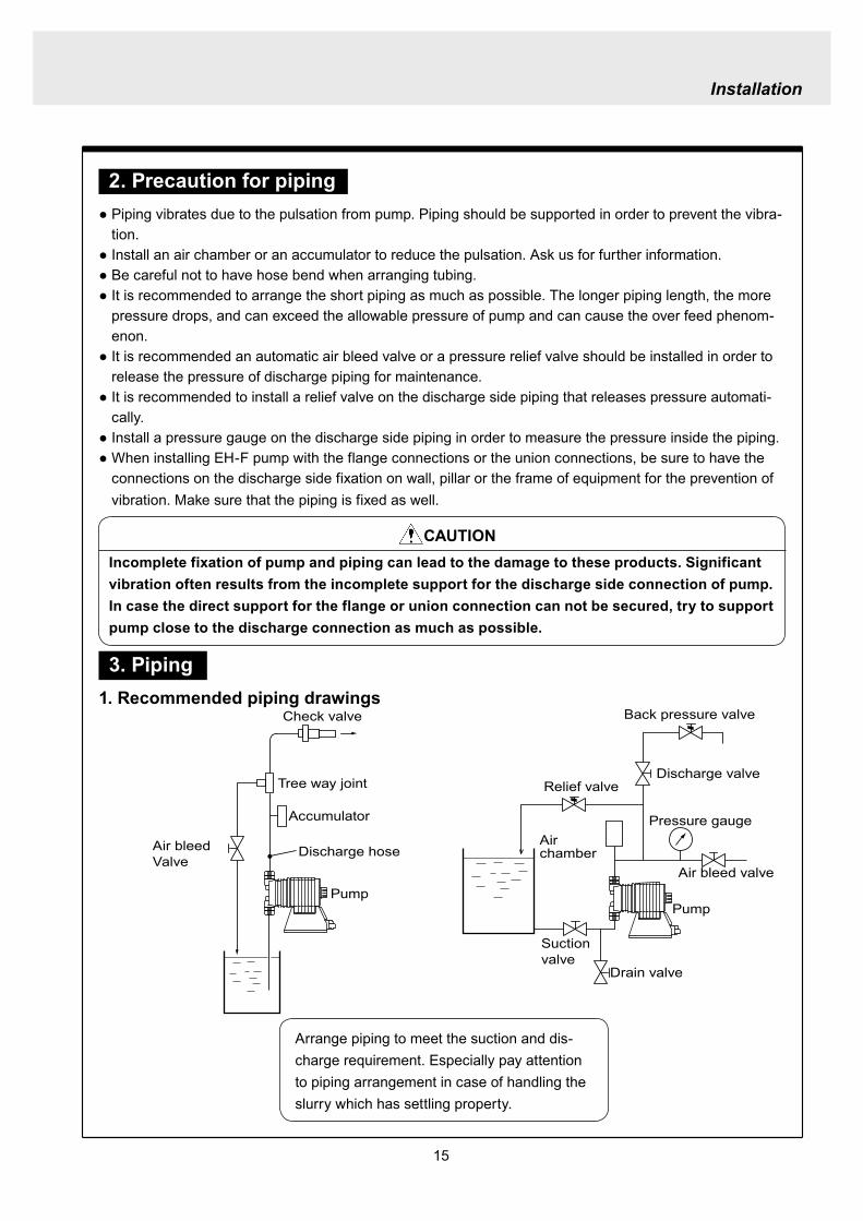
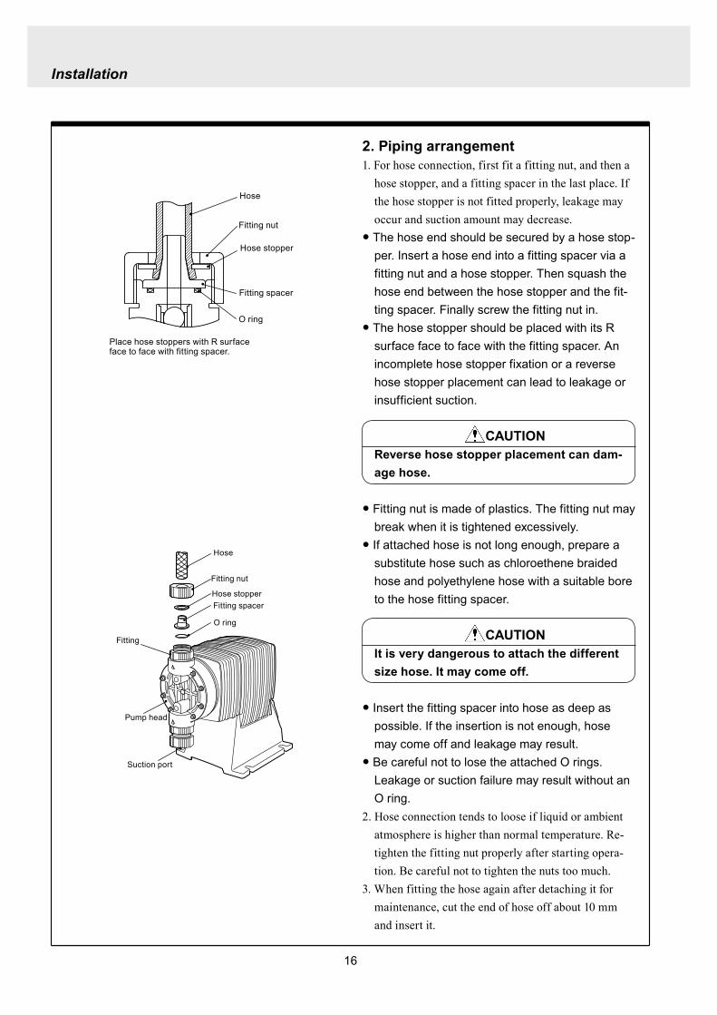
Installation
16
Hose
Hose stopper
Fitting spacer
O ring
Fitting nut
Place hose stoppers with R surfaceface to face with fitting spacer
Hose
Hose stopperFitting spacer
O ring
Fitting nut
Fitting
Suction port
Pump head
2 Piping arrangement1 For hose connection first fit a fitting nut and then a
hose stopper and a fitting spacer in the last place If the hose stopper is not fitted properly leakage may occur and suction amount may decrease
The hose end should be secured by a hose stop-per Insert a hose end into a fitting spacer via a fitting nut and a hose stopper Then squash the hose end between the hose stopper and the fit-ting spacer Finally screw the fitting nut in
The hose stopper should be placed with its R surface face to face with the fitting spacer An incomplete hose stopper fixation or a reverse hose stopper placement can lead to leakage or insufficient suction
CAUTIONReverse hose stopper placement can dam-age hose
Fitting nut is made of plastics The fitting nut may break when it is tightened excessively
If attached hose is not long enough prepare a substitute hose such as chloroethene braided hose and polyethylene hose with a suitable bore to the hose fitting spacer
CAUTIONIt is very dangerous to attach the different size hose It may come off
Insert the fitting spacer into hose as deep as possible If the insertion is not enough hose may come off and leakage may result
Be careful not to lose the attached O rings Leakage or suction failure may result without an O ring
2 Hose connection tends to loose if liquid or ambient atmosphere is higher than normal temperature Re-tighten the fitting nut properly after starting opera-tion Be careful not to tighten the nuts too much
3 When fitting the hose again after detaching it for maintenance cut the end of hose off about 10 mm and insert it
17
Installation
4 Check valveEH-F35 45 (VCV6PC) types are attached with a check valve Fit the check valve to piping in the fol-lowing cases
1 The suction side liquid level is higher than the dis-charge side liquid level (Fig A) When injection point is below the liquid level of suction side at atmospheric pressure
2 The suction side pressure is higher than the discharge side pressure (Fig B)
3 The discharge side liquid level is higher than the suction side liquid level but the differential height between both liquid level is 5 m or below (Fig C)
4 The loading pressure of piping resistance and dis-charge head to the pump is under 013 MPa
Suction side Discharge side
Figure A
Figure B
5m
Figure C
To chemical tankor vessel
Remove check valve
3 Piping for bleedingPrior to bleeding disconnect hose and point a hose end at a suction tank or vessel Remove a check valve if it is attached on the discharge side piping
18
Installation
R12
Oslash12
5 Check valve mounting1 Tap the female thread of NPT12 at an injection
point Check valve is provided with the male thread of R12 Cut off the unused portion to fit it on a pip-ing
2 Apply seal tape on the threaded portion of the check valve and screw it in the injection point Pinch the check valve body lightly with a spanner and tighten it for easy mounting
3 When fitting a hose into a check valve with the check valve on main pipe tighten the fitting nut holding the check valve body by hand
4 Cut the end of check valve(empty 12) accordingly when mounting it in a small pipe It is recommended the end of the check valve comes at the centre of pipe bore
It is recommended to mount a check valve via a valve for maintenance Provide NPT12 female thread and screw it in Valve should be resistant to the chemical liquid in use
Valve
Check valve
Check valve body
Apply seal tape
Fitting nut
Pipe
Cut the end nozzle offif it is too long compared topipe bore
6 Flange connection and union connection1 Flange units and union sockets are packed apart from pump body Fit the flange units or the union sockets to
pump body before use Refer to the following figures2 Secure the sealing by fitting O rings to each connection
CAUTIONWhen mounting flange units or union sockets to pump body be careful not to allow O ring to get out of the groove Especially pay attention to the O ring on the groove on suction side
3 Fix the flange units or the union sockets to the pump body by tightening fitting nuts In this case first tighten the fitting nuts by the hand and then re-tighten it by 90 degrees with a spanner
CAUTION
Fitting nut is made of plastics The fitting nut may break when tightened excessively
Flange connection type
19
Instillation
Flange
Flange
Fitting nut
O ring
O ring
Elbow
Pump body
Fitting nut
Drain
Discharge
Air chamber
7 Accumulator and air chamber mountingInstall an accumulator or an air chamber on piping for the prevention of the vibration from the pulsation of pump discharge hose
20
Installation
8 Piping (General notes)1 Keep piping short and less bends Do not make the projections where air can remains
2 Support piping to avoid having the pump subject to the piping weight especially when wet-end mate-rial is made of PVC
3 In case of transferring the slurry which tends to settle do not make U shape on piping A drain plug is required at the lowest portion of piping as well
4 In case of transferring the viscous or toxic liquid or the liquid which tends to settle provide the piping for cleaning for the purpose of maintenance
5 In case of transferring the high temperature or low temperature liquid the telescopic motion of piping from temperature variation should be taken into consideration
6 Select pipe materials based on a through examination of the corrosive resistance and the estimated pressure applied to piping
7 Do not allow any adhesive agent to get in pump when connecting PVC-made pipe on the discharge side piping
8 Clean the inside of piping before installing pump in it
9 A relief valve is required to protect pump and piping Install a relief valve on the discharge piping near the pump
9 Suction piping1 Regarding suction piping a flooded suction system should be realized The bore of suction piping is
recommended to be larger than that of pump suction port
2 Each joint of suction piping needs to be mounted carefully in order to prevent air from coming in Air influx into piping may cause discharge performance failure and instability
10 Discharge piping1 Mount a relief valve on the discharge piping near pump A discharge valve should be mounted beyond
the relief valve
2 The pressure resistance of discharge piping should be higher than the set pressure of relief valve Mount each joint carefully
21
Installation
4 Electrical wiring
1 Power cord connection
Electrical works and the handling of power source must be done by qualified person
Do not operate pump with the wet hand
Make sure that power is not turned on while working on wirng
Do not dismantle electronic circuit
Electronic circuit may be broken Never apply other voltages than a rated voltage
WARNING
CAUT ION
High power equipment
CAUTION Avoid sharing a power source with a high
power equipment This can lead to the fail-ure of the electronic circuit of control unit due to extremely large surge voltage
The noise from an inverter can cause fail-ure
22
Installation
P
Surge absorption element
PNoise cut transformer
CAUTION
2 Wiring procedure
Electronic circuit of control unit may be failed by extremely large surge voltage Do not use the pump near to the high power equipment of 200V or more which may generate large surge voltage If the use of high power equipment is inevitable take either of the following measuresa Install a surge absorption element such
as varister with 2000A or more durability on the power point
b Install a noise cut transformer
CAUTION
Only qualified operatorsservice staff should be in charge of the related electrical arrange-ment and control of the power source Failure to observe this instruction may result in injury to person or damage to assets
Never connect wires while power is turned on otherwise an electrical shock or a short-circuit of controller may result Be sure to turn off power before wiring
Internal circuit is still electrified right after turning off power Take 1 minute or more to start wiring
Do not band a power cable either electrical wires or relay output wires
Earthing wire is equipped with a jumper pin Keep the jumper pin equipped in use
Do not combine the EXT or STOP signal line with a power cord or a power cable Do not com-bine power source line with the EXT or STOP signal line by a concentric cable (5 wires cable or so) Otherwise noise come about through EXT and STOP wires due to the induction effect from power cable and it may results in wrong operation or the failure of pump
Regarding frequent ON-OFF operation it is recommended to stop pump thorough STOP input terminal but not by connecting or disconnecting power source When connecting and discon-necting power cord can not be avoided it should be within 6 times an hour
23
Installation
Procedure to connect the signal cordUse DIN connector of five poles and four polesThe following connectors made by Binder in Germany are recommendedAsk IWAKI for the detail of Binder connector 5 poles 713 series 99-0436-10-05 for input signal 4 poles 715 series 99-0430-15-04 for level sensor
The following connector made by Hirschmann in Germany is recommendedAsk IWAKI for the detail of Hirschmann connector 4 poles GDS307 for output
The following procedures are based on the connector made by Binder and HirschmannIf a similar connector is used the wiring should be made according to the instruction manual of the manufacturer of connector
In case of Binder connector(1) Dismantle the connector and pass the wire through it Outer diameter of the cable should be oslash4-6
Using the different cable in diameter the connector can not be sealed properly
(2) Strip the cable ends and insert wire to the appropriate positions and connect them with screwsThe maximum allowable cross section of the wire is 075mm2
(3) After connecting the wire assemble the connector securely Slightly pull the cord to confirm that the cord connection is secured Perfect sealing can not be obtained unless the cord connection is loose
24
Installation
In case of Hirschmann connector(1) Dismantle the connector and pass the wire through it Insert a minus screw driver into the place shown by
ldquoLIFTrdquo and lift it up Outer diameter of the cable should be 35-6 mm Using the different cable in diam-eter the connector can not be sealed properly
(2) Strip the cable ends and insert wire to the appropriate positions and tighten them with screwsThe maximum allowable cross section of the wire is 075mm2
(3) After connecting wire assemble the connector securely Slightly pull the cord to confirm that the cord connection is secured Perfect sealing can not be obtained unless the cord connection is loose
Terminal position
NA Not Applicable
Connection of level sensorThe controller corresponds to two stage level sensor Connect the pre-alarm signal to Pre-STOP and the alarm signal to STOP When the pre-alarm signal comes in the orange lamp lights but the pump does not stop When a contact type is used connect wires to STOP and COM2 For open collector output level sensor Pay attention to the polarity Pre-Stop and STOP are plus (+) and COM2 is minus (-) (Max charged voltage 5V Current 18mA) For contact output level sensor Use the one designed for electronic circuit and the minimum applicable load of 1mA or less
Connection inside connector 1 STOP 2 Pre-STOP 3 Free 4 COM2
1
2
3
4 CLOSE
ON
PUMP
Level Sensor(STOP)
OPEN
Pulse
COM
+12VDC
NA
ANA(4-20)
Pre-STOP
STOP
COM
NA
OUT
25
Installation
Stop functionStop function is the function to stop the pump by the external signal Connect the wires to STOP and COM2 in the same way as the level sensor connection
CAUTION
Frequent stop and start of pump should be done by using STOP function (ON and OFF of STOP terminal) If you can not use STOP function and are forced to operate pump by turning OFF and ON of power source ON and OFF of power source should be limited to six times an hour
Pulse signal inputPulse signal input is used when the pump runs in the DIV or MULT of EXT modeDIV means dividing and MULT means multiply In case of open collector signal Pay attention to the polarity Pulse is plus (+) and COM1 is minus (-) (Max charged voltage 5V Current 18mA) In case of contact signal Use the one designed for electronic circuit and the minimum applicable load of 1mA or less
Connection inside connector 1 Free 2 Pulse 3 Free 4 12VDC 5 COM
3
2
4
15
Analog signal inputAnalog signal input is used when the pump runs in ANAR or ANAV of EXT modeANAR means analog rigid and ANAV means analog variable
Connection inside connector 1 ANA 2 Free 3 Free 4 Free 5 COM
3
2
4
15
26
Installation
Output signalOUT Photo MOS relay outputStandard is output synchronous with stroke Output is activated synchronous with each pump stroke
Connection inside connector 1 OUT 4 OUT
OUT 1
2
34
Surge voltage The electronic circuit of the control unit may be affected by excessively high surge voltage Do not operate the pump near the high-power elec-trical equipment of 200V or above that generates high surge voltage Under unavoidable circumstances take either of the following measures(1) Use a surge absorbing element (such as a
varistor with the surge resistance of 2000A or more) at the pump power supply connection
(2) Use a noise-cut transformer
Surge absorbing element
Noise-cut transformer
1 Preparation for pump operationBefore pump operation check that
bull Liquid tank is filled enough Supply liquid if it is less than the required levelbull There is no liquid leakage or congestion due to breakagebull Both suction and discharge side valves are openedbull Pump is connected to the predetermined power source correctlybull Electrical wiring is correct and there is no possibility of a short circuit or current leakage
2 BleedingBleeding is a process to eliminate the air inside the suction-side piping Be sure to carry out an air elimi-nation prior to initiating the pump operation after replacing the liquid inside a tank and after a long peri-od of storage Air gushes together with chemical liquid when carrying our bleeding For safety reasons first turn the end of a bleeding hose to a tank or a container
CAUTION
Some liquids may cause skin trouble or affect the quality of mechanical parts Wipe off chemi-cal liquid immediately when they splash on the hand or mechanical parts
27
Operation
1 Pump Operation
WA R N I N G Wear protective clothing
Wear protective clothing such as a protective mask safety gloves or so when handling chemical liquid
Do not operate pump with a discharge-side valve completely closed Operating the pump with the discharge-side valves fully closed may cause the liquid spillage or
the extremely high pressure inside the pump or the discharge-side pipingtubing This could lead to a piping burst Be sure not to operate pump with the discharge-sides valve closed
CAU T I O N A long time dry running (longer than 30 minutes) may cause the pump overheat and it could lead
to the deformation of the pump unit consists of a pump head and valve cases or so or may loosen the pump head fitting and result in liquid leakage
If the hex socket cap bolts on a pump head are loosened liquid leakage may resultBe sure to fasten all the 6 or 8 hex socket cap bolts tightly before starting the initial pump opera-tion And periodically check the looseness of the bolts on the pump head and retight the bolts as necessary
bull Tightening torque255NbullmTighten all the bolts diagonally applying equal tightness
If electric wiring gets wet due to accidental liquid spillage fire or electrical shock may occur Never get it wet When the electric wiring gets wet turn off power and wipe the liquid away
A frequent ON-OFF operation should be conducted by using STOP function(ON - OFF signals to STOP terminal) In case the STOP function is not available for the ON-OFF operation the ON - OFF operation by turning onoff power should be limited to six times an hour
4
28
3 Procedure for bleeding
Check valve should be removed
To tank or drain pan
100
75
50
25
0 25 50 75 100
(Fixed stroke length)
Stroke length adjustment
240spm
180spm
120spm
Flow
rate
Operation
[1] Extend the tube connected to the discharge-side fitting nut of pump to a chemical tank or a drain pan Then start pump operationbull Remove a check valve if it is installed on dis-
charge-side
[2] Operate the pump for about 10 minutes to eliminate air completely
[3] When the air in pump head is completely eliminated and liquid is replaced return the discharge-side tube to the regular tubing position
[4] Finally make sure there is no leakage in any section
4 Discharge capacity adjustmentDischarge capacity can be adjusted by both the stroke length adjustment and the stroke rate adjust-ment but basically adjust it via the stroke rate adjustment Stroke length adjustment is an auxiliary way to cover the range where the stroke rate adjustment can not reachPay attention to the following for correct procedure
Stroke rate adjustment(1) For some liquids which diffuses gas such as sodium hypochlorite and hydrazine solution adjust discharge capac-
ity by means of the stroke rate adjustment with the stroke length about 100 Gas lock may occur if the stroke length is set to short
(2) When the back pressure on discharge side is high adjust discharge capacity by the stroke rate adjustment with the stroke length about 100
(3) In case reaction is greatly influenced depending on the discharge capacity per pump shot in the application of neutralization or titration adjust discharge capacity by the stroke rate adjustment with the shortened stroke length and reduce the discharge capacity per shot
1 Discharge capacity adjustment procedureAppropriate stroke length and stroke rate are decided on the pump operating condition and liquid characteristics Following ways are recommended for proper calibration
(1) Set stroke length at 100 and roughly adjust discharge capacity by adjusting stroke rate
(2) Measure discharge capacity(3) If the measured capacity is below the wanted value
increase the stroke rate and measure again the dis-charge capacity
(4) Adjust stroke length for the fine adjustment of discharge capacity(5) Determine a discharge capacity at the last and confirm the wanted capacity is discharged
CAUTION
29
100
75
50
25
0 60 120 180 240spm
Fixed stroke length
Stroke rate adjustment
Flow
rate
Screw driverOPEN
LOCK
100
75
50
25
0 25 50 75 100
Fixed stroke rate
Flow
rate
Stroke length adjustment
Operation
2 Stroke rate adjustmentStroke rate is adjusted by the key operations of control unit Control the plunger stroke rate per minute from 1 to 240 spm via control unit
3 Stroke length adjustmentStroke length adjustment knob is locked with a screw Loosen the screw before adjustment and lock it afterwards
(1) Turn on pump and adjust the discharge capacity by turning the stroke length adjusting knob while pump is running
(2) The left graph shows the relation between stroke length and discharge capacity The maximum dis-charge capacity is shown on the name plate
bull The usage between 40 and 100 is practi-cal
Do not turn the stroke length adjusting knob when pump stops
CAUTIONBe sure to tighten the screw on the adjust-ment knob after an adjustment The knob may rotate unintentionally due to a loose fixation This may result in the fluctuation in a discharge rate
30
Mode ParameterDefault value
Setting range Step
Manual operation Stroke speed 240 1-240DIV setting Dividing ratio frasl 1 1-9999
MULT setting Multiply ratio times1 times1-9999ANA R setting 4-20 4-20 20-4 0-20 20-0
ANA V setting
P1 amperage 40 00-200P1 stroke speed 0 0-240P2 amperage 200 00-200P2 stroke speed 240 0-240
User setting
EXT operation ANA V DIV MULT ANA R ANA V
Anti-chatteringMECH MECH ELECST05 ST05 ST20 ST50FT01 FT02 FT04
Buffer memory MEM-N MEM-N MEM-Y
111-
011
011
2 Control unit operationEH-F type pump is controlled by means of setting or changing the setting values of the controller Control functions are various at each operation mode Read this section carefully before operation
Default parameter values
5 Full operationPut pump in use after bleeding and adjusting discharge capacityPump runs in manual operation or in accordance with the setting of control unit
6 Manual operationStarting pump After turning on power ON lamp (Green) appears and display shows WAIT mode For
the first time to turn on power MAN lamp appears and pump starts after pushing STARTSTOP key once
Stop pump Push STARTSTOP key to turn off MAN lamp and stop pump Pump starts and stops every time STARTSTOP key is pressed
7 EXT operationRefer to the next section of 2 Control unit operation
8 Shout down When pump will not in use for a long time (one month or more)
Run pump with clean water about 30 minutes in order to clean the wet-end parts and the inside of pip-ing before storage
When re-starting pump after a long time storage If pump dose not suck up liquid clean valve sets and remove the sticking foreign matters Carry out an air elimination and adjust discharge capacity when air stays inside pump head Refer to page 28 3 Procedure for bleeding
Operation
---
-
31
AN
A V
(Ana
log
var
iabl
e)
DIV
(Pul
se d
ivid
ing)
MU
LT(P
ulse
mul
tiply
)A
NA
R(A
nalo
g ri
gid)
SE
TS
ET
Use
r mod
e
EX
T m
ode
sele
ctio
n
EX
T
EX
TE
XT
EX
TE
XT
EX
T EX
T
EX
T
EX
T
EX
T
EX
T
EX
T
EX
T
EX
T
EX
T
EX
T
EX
T
EX
T
3 sec
onds
or m
ore
Wai
t mod
e
Set
ting
of fi
xatio
n pa
ttern
EX
T m
ode
Man
ual o
pera
tion
Set
ting
of s
troke
num
ber
AN
A R
(Ana
log
rigi
d)M
ULT
(Pul
se m
ultip
ly)
DIV
(Pul
se
div
idin
g)
AN
A V
(Ana
log
var
iabl
e)
anti-
chat
terin
gse
tting
dis
play
Setti
ng o
f div
idin
g ra
tioS
ettin
g of
cou
nt n
umbe
r
Curre
nt va
lue of
P1
Stro
ke nu
mbe
r of P
1
Curre
nt va
lue
of P
2
Stro
ke nu
mbe
r of P
2
EX
T O
pera
tion
Dis
play
EX
T se
tting
mod
e
Buf
fer m
emor
yse
tting
dis
play
Pow
er O
N
spm
MA
Nsp
m
spm
DIV
DIV
SE
TS
ET
MU
LT
MU
LTsp
mA
NA
V
spm
AN
AR
AN
AR
SE
Tm
AS
ET
mA
spm
AN
A
V
P1
mA
SE
T
spm
AN
A
V
P1
AN
AR
SE
Tm
A
AN
AR
SE
Tm
AS
ET
AN
A
V
P 2
SE
T
spm
AN
A
V
P 2
AN
AR
SE
Tm
A
AN
A
V
SE
TS
ET
SE
T
SE
T
SE
T
SE
T
SE
T
SE
T
SE
T
SE
T
SE
TS
ET
1 Overview Operating Scheme
Operation
1 means automatic transfer WAIT mode is selected when the power is switched on for the first time On and after the initial power activation pump restores the previous status right before the power is switched off
2 Regarding MANUAL mode pump starts operation by pushing STARTSTOP key at WAIT modePushing STARTSTOP key again the pump stops and returns to WAIT mode
3 Regarding EXT operation pushing EXT key at WAIT mode the pump moves to EXT mode and starts operationPushing STARTSTOP key stops the operation and returns the pump to WAIT mode
4 The change of each setting of EXT operation is accessible by pushing EXT key at EXT mode Pushing EXT key after the setting pump starts in EXT operation according to the changed setting
5 Pushing EXT key for 3 seconds at WAIT mode pump moves to USER mode At USER mode the EXT mode selection and the detailed setting such as the setting of buffer memory or so can be obtained
For details refer to each section of 2 Pump operation
2 Pump operation1 Operation of controller
Before turning on power confirm the specified power source on the nameplate
CAUTION
Connecting any other powers than the one shown on nameplate to pump is strictly prohibitedIt could lead to pump trouble or failure
Operation
32
1 Turning on powerDisplay shows WAIT mode when pump is turned on for the first time After the initial power activation the pump restores the previous mode right before the power was turned off last time If power is turned off at any setting modes WAIT mode appears at the next power activation
Stroke speed setting value is shown on display at WAIT mode ON lamp lights (Green)
EXT
EH-F ControllerSTARTSTOP
ON STOP
spm
33
2 Manual operation(1) Stroke speed can be adjusted by and
keys The figure changes quickly when either or key is depressed The picture below
shows the stroke speed is set to 160 spm
EXT
EH-F ControllerSTARTSTOP
ON STOP
spm
EXT
EH-F ControllerSTARTSTOP
ON STOP
MAN spm
EXT
EH-F ControllerSTARTSTOP
ON STOP
spm
(2) Push STARTSTOP key once to start the pump operation MAN indication appears and ON lamp blinks synchronously with each stroke
(3) MAN indication disappears and ON lamp stops blinking as STARTSTOP key is pushed again Pump enters WAIT mode
Operation
Operation
34
EXT
EH-F ControllerSTARTSTOP
ON STOP
ANA V
P1 SET mA
EXT
EH-F ControllerSTARTSTOP
ON STOP
P1 SET
ANA V spm
EXT
EH-F ControllerSTARTSTOP
ON STOP
spm
EXT
EH-F ControllerSTARTSTOP
ON STOP
ANA V spm
(4) Set the current value at P1 Figure increases or decreases as or key is pushed The pic-ture below shows 80 mA is set to point 1
EXT
EH-F ControllerSTARTSTOP
ON STOP
ANA V
P1 SET mA
(5) Pushing EXT key once spm appears on the display while mA disappears The picture below shows the number of strokes at P1
EXT
EH-F ControllerSTARTSTOP
ON STOP
P1 SET
ANA V spm
3 EXT operation (ANA V mode)(1) Push STARTSTOP key to move to WAIT mode
if pump is in another mode Go to next step if pump is in WAIT mode
(2) ANAV indication appears and pump enters an EXT mode as EXT key is pushed once Pump starts operation in accordance with current sig-nals and various settings ON lamp blinks at each pumping during operation Pump is con-trolled via the EXT mode which was select-ed at USER mode The initial setting of EXT mode is ANA V mode Select a preferable EXT mode in USER mode The picture below shows ANA V mode (The spm on the display changes according to input signals)
(3) Push EXT key once when pump is running in ANA V mode Display indicates the setting display of ANA V mode spm indication dis-appears and P1 SET and mA indications appear on the screen
(6) Set the number of strokes at P1 Figure increasesdecreases as key is pushed Picture below shows 10 spm is set for point 1
Operation
35
(7) Push EXT key to move to the setting display of the current value at P2 P1 and spm disap-pear and P2 and mA appears instead
EXT
EH-F ControllerSTARTSTOP
ON STOP
ANA V
P 2 SET mA
EXT
EH-F ControllerSTARTSTOP
ON STOP
ANA V
P 2 SET mA
EXT
EH-F ControllerSTARTSTOP
ON STOP
P 2 SET
ANA V spm
(11) Push EXT key to return to EXT mode Pump starts to run in ANA V mode on the setting of (4) through (10) ON lamp starts to blink at each pumping
EXT
EH-F ControllerSTARTSTOP
STOPON
ANA V spm
EXT
EH-F ControllerSTARTSTOP
ON STOP
P 2 SET
ANA V spm
EXT
EH-F ControllerSTARTSTOP
ON STOP
spm
(8) Set the current value of P2 by pushing and keys Picture below shows 180 mA is set to
point2
(9) Pushing EXT key once spm appears on the display while mA disappears The picture below shows the number of strokes at P2
(10) Set the number of strokes at P2 by pushing and keys Picture below shows 200
spm is set to point 2
(12) Pushing STARTSTOP key pump enters WAIT mode and pump stops ON lamp stops blink-ing and ANAV indication disappears
CAUTIONWhen the setting of the buffer memory is OFF keep the number of strokes in the dividing operation 240 spm or below The input signals to operate the pump over 240 spm can cause an unstable pump operationWhen the setting of the buffer memory is ON the pump operates for all the input pulse signalsPump keeps operating after all the signals are stopped in this case Be careful when setting of buffer memory
Operation
36
EXT
EH-F ControllerSTARTSTOP
ON STOP
DIV
SET
EXT
EH-F ControllerSTARTSTOP
ON STOP
DIV
SET
EXT
EH-F ControllerSTARTSTOP
STOPON
DIV spm
EXT
EH-F ControllerSTARTSTOP
ON STOP
spm
(2) Pushing EXT key DIV appears and pump starts operation in the ratio of input pulse sig-nals a pumping ON lamp blinks synchronous-ly at each pumping The initial setting of EXT selection is ANA V mode Change mode to DIV mode via USER mode Refer to P 40 for detail information
(3) Push EXT key while pump is operating in DIV mode Pump stop running and SET indication appears on the DIV setting display in stead of spm indication
(4) Enter a dividing ratioFigure increasesdecreases when key is pushed The picture below shows 10 is set
4 EXT operation (DIV mode)
(1) Push STARTSTOP key to move to WAIT mode if pump is in another mode Go to next step if pump is in WAIT mode
CAUTIONOn condition the setting of buffer memory is OFF do not input any pulse signals during the pumping motions for a input pulse signal in the multiply operation These input pulse signals are cancelledWhen the setting of buffer memory is ON pump operates for all the input pulse signals
Operation
37
EXT
EH-F ControllerSTARTSTOP
ON STOP
spm
EXT
EH-F ControllerSTARTSTOP
STOPON
DIV spm
EXT
EH-F ControllerSTARTSTOP
ON STOP
spm
EXT
EH-F ControllerSTARTSTOP
ON STOP
MULT
(5) Push EXT key to return to EXT operating mode Pump starts to run on the setting at item (4) ON lamp blinks synchronously at each pumping
(6) Pushing STARTSTOP key pump enters WAIT mode and pump stopsDIV indication disappears and ON lamp stops blinking
5 EXT operation (MULT mode)
(2) MULT indication appears and pump starts running in an EXT operation mode in the ratio of an input pulse signal pumpings as press-ing EXT key ON lamp blinks at each pump-ing Display shows the rest of the number of strokes In MULT mode the number of strokes is equal to the setting value in manual opera-tionThe initial setting of the EXT mode selection is ANA V mode which is the operation in pro-portion to current First select MULT mode via USER mode Refer to P 40 for detail informa-tion
(1) Push STARTSTOP key to move to WAIT mode if pump is in another mode Go to next step if pump is in WAIT mode
Operation
38
EXT
EH-F ControllerSTARTSTOP
ON STOP
spmEXT
EH-F ControllerSTARTSTOP
ON STOP
ANAR spm
EXT
EH-F ControllerSTARTSTOP
ON STOP
MULT
SET
EXT
EH-F ControllerSTARTSTOP
ON STOP
MULT
EXT
EH-F ControllerSTARTSTOP
ON STOP
spm
EXT
EH-F ControllerSTARTSTOP
ON STOP
MULT
SET
(5) Push EXT key to return to MULT mode(3) Pushing EXT key when pump is running in the multiply operation calls the setting display of MULT mode and SET indication appearsPump stops running and ON lamp stop blinking
(4) Enter the number of pumpings per input signalFigure increasesdecreases when key is pushed The picture below shows the pump-ing number is set to 1800 times per an input signal
6 EXT operation (ANA R mode)(1) Push STARTSTOP key to move to WAIT mode
if it is in another mode Go to next step if it is in WAIT mode
(6) Pushing STARTSTOP key recalls WAIT mode and pump stops spm indication appears in stead of MULT indication
(2) Pushing EXT key ANAR appears and pump starts running in the ratio of an input pulse sig-nal pumpings ON lamp blinks at each pump-ing The initial setting of the EXT mode selec-tion is ANA V mode which is the operation in proportion to current is selected First select ANA R mode in USER mode Refer to P 40 for more information
Operation
39
EXT
EH-F ControllerSTARTSTOP
ON STOP
ANAR
SET mA
EXT
EH-F ControllerSTARTSTOP
ON STOP
ANAR spm
EXT
EH-F ControllerSTARTSTOP
ON STOP
ANAR
SET mA
EXT
EH-F ControllerSTARTSTOP
ON STOP
spm
(4) Figure increasesdecreases when key is pushed The picture below is when it is set to 0-240 spm for 20-4 mA
(5) Push EXT key to return to EXT mode Pump starts to run on the setting at item (4) ON lamp blinks synchronously at each pumping
(6) When pushing STARTSTOP key pump enters WAIT mode and stops running ON lamp stops blinking and ANAR disappears
(3) Pushing EXT key when pump is running in the multiply operation calls the setting display of ANAR mode and SET and mA indications appear while spm disappears Pump stops running and ON lamp stops blinking
Operation
40
EXT
EH-F ControllerSTARTSTOP
ON STOP
ANA V
(5) Push EXT key to confirm the desired EXT mode Pump displays the EXT mode selection The picture below shows DIV appears to indi-cate DIV mode is selected
EXT
EH-F ControllerSTARTSTOP
ON STOP
DIV
EXT
EH-F ControllerSTARTSTOP
ON STOP
SET
EXT
EH-F ControllerSTARTSTOP
ON STOP
spm
EXT
EH-F ControllerSTARTSTOP
ON STOP
spm
EXT
EH-F ControllerSTARTSTOP
ON STOP
SET
7 USER settingThe setting of each function is changed in USER mode Have the pump entering WAIT mode in order to move to USER mode OUT (Output) is synchronous with spm and it can not be changed
7-1 EXT mode selection Any one of DIV (pulse dividing) MULT (pulse multiply) ANAR (analog rigid) or ANAV (analog vari-able) can be active in EXT mode The initial mode when shipped from factory is ANAV
(1) Push STARTSTOP key to move to WAIT mode if it is in another mode If it is in WAIT mode go to next step
(2) Press EXT key for more than 3 seconds to move to USER mode The picture below shows pump enters the EXT mode selection
(3) Pushing EXT key SET appears and display shows the mode currently set Picture below shows ANA V mode is selected
(4) Push or key to select a desired EXT mode The picture below shows DIV mode is selected
(6) Push STARTSTOP key to move to WAIT mode spm appears while DIV goes out
Operation
41
EXT
EH-F ControllerSTARTSTOP
ON STOP
spm
EXT
EH-F ControllerSTARTSTOP
ON STOP
ANA V
EXT
EH-F ControllerSTARTSTOP
ON STOP
SET
(3) Push key once
EXT
EH-F ControllerSTARTSTOP
ON STOP
(4) Push key again to move to the anti-chatter-ing setting display
EXT
EH-F ControllerSTARTSTOP
ON STOP
(5) Pushing EXT key display shows the mode cur-rently set and SET appears on it The picture below shows when MECH is selected
EXT
EH-F ControllerSTARTSTOP
ON STOP
SET
7-2 Setting of anti-chattering Anti-chattering function is settable against the incoming pulses during the DIV or MULT operation For the long chattering of mechanical contact such as relay set a large figure via MECH For the high speed (high frequency) chattering of the semi-conductor type contact such as transistor set a small figure via ELEC ST05 of MECH is initial setting
(6) Select MECH by or key for a mechani-cal contact And select ELEC for a semi-conductor contact The picture below shows ELEC is selected
(1) Push STARTSTOP key to move to WAIT mode if it is in another mode If it is in WAIT mode go to next step
(2) Press EXT key for more than 3 seconds to move to USER mode The picture below shows pump enters the EXT mode selection
Operation
42
EXT
EH-F ControllerSTARTSTOP
ON STOP
SET
(7) Push EXT key to display the current set state The picture below shows FT01 is selected
EXT
EH-F ControllerSTARTSTOP
ON STOP
SET EXT
EH-F ControllerSTARTSTOP
ON STOP
EXT
EH-F ControllerSTARTSTOP
ON STOP
spm
7-3 Setting of buffer memoryIn case pump operation can not catch up with the input pulse signals in DIV or MULT operation exces-sive pulse signals can be put in memory up to 65535 pulses However the excessive pulses can not be restored if once power is off or mode is changed
EXT
EH-F ControllerSTARTSTOP
ON STOP
spm
(2) Press EXT key for 3 seconds or more to move to USER mode The picture below shows the EXT mode selection display
EXT
EH-F ControllerSTARTSTOP
ON STOP
ANA V
(8) Set a large figure for the long chattering by or key and set a small figure for high speed (high frequency) chattering The picture below shows FT04 is selected
(9) Push EXT key to return to the anti-chattering setting display SET indication disappears
(10) Push STARTSTOP key to return to wait mode spm indication appears
(1) Push STARTSTOP key to move to WAIT mode if it is in another mode If it is in WAIT mode go to next
Operation
43
(3) Push key once
EXT
EH-F ControllerSTARTSTOP
ON STOP
(7) Push or key in order to set buffer memo-ry to ON or OFF Select MEM-Y to set it ON Select MEM-N for OFF setting The picture below shows when ON is set
EXT
EH-F ControllerSTARTSTOP
ON STOP
SET
(4) Push key once again
EXT
EH-F ControllerSTARTSTOP
ON STOP
(8) Push EXT key to return to the buffer memory setting display SET indication disappears
EXT
EH-F ControllerSTARTSTOP
ON STOP
(9) Push STARTSTOP key to return to WAIT mode spm indication appears
EXT
EH-F ControllerSTARTSTOP
ON STOP
spm
(5) Push key once again and the buffer memory setting display is shown
EXT
EH-F ControllerSTARTSTOP
ON STOP
(6) Push EXT key in order to display the current set state SET indication appears The picture below shows the buffer memory is set to OFF
EXT
EH-F ControllerSTARTSTOP
ON STOP
SET
Operation
44
8 Bleeding amp self-primingAt WAIT mode Manual operating mode and EXT operating mode pump operates at max speed tak-ing priority over any functions when both and keys are pushed at once Pump runs at max speed only when both keys are depressed Pump state returns to the previous mode once either or key is released Pressing and keys for 10 seconds keeps pump running at maximum speed In this state this fixation is released when pushing either or key once and pump returns to the previous mode
(1) When pump is running in ANAV mode
EXT
EH-F ControllerSTARTSTOP
ON STOP
ANA V spm
(2) Pump start to run at full speed when and keys are pressed at once Display shows
PRIME If either or key is released pump returns to the previous mode In this case pump returns to ANAV mode
EXT
EH-F ControllerSTARTSTOP
ON STOP
ANA V
(3) Pressing both and keys simultaneously for 10 seconds or more pump continues to run at full speed even if both keys are released In this case indication appearsPush either or key to release this state indication disappears and pump returns to the previous mode In this case pump returns to ANAV mode
EXT
EH-F ControllerSTARTSTOP
ON STOP
ANA V
Operation
45
10 Error display and release(1) In case Input signals fall to 4 mA or below while
4-20 or 20-4 is set to ANA R mode pump stops with DISCN blinking and Err on dis-play
(2) This error state can be released by push-ing STARTSTOP key and pumps enters wait mode In this case check the wiring and input signals
EXT
EH-F ControllerSTARTSTOP
ON STOP
ANAR
Err
spm
EXT
EH-F ControllerSTARTSTOP
ON STOP
spm
9 Key lockKey lock function is to prevent pump from being operated by some other person than user If STARTSTOP key is pressed for five seconds or more when pump is running or stops all key operations become ineffective with LOCK indication on display This function can be released by pressing STARTSTOP key for 5 seconds while LOCK lights
EXT
EH-F ControllerSTARTSTOP
ON STOP
MAN spm
LOCK
46
Do not conduct a maintenance work with the wet hands It can cause an electric shock
Before dismantling pump be sure to turn off power and check the pump is not electrified Do not
start a dismantlement work after stopping the pump by pushing the STARTSTOP key only Put up
the sign of ldquoMaintenance work is in progressrdquo in order to prevent a pump switch from turning on
unintentionally during the work Release the pressure of discharge piping and drain the liquid from
the wet end parts And then clean the inside of pump head
Wear protective clothing such as a protective mask globes goggles and chemical-proof wear
according to the handled chemical liquid during the work
WARNING
5 Maintenance
1 Trouble shootingTrouble Cause Troubleshooting
Pump dose not start Faulty wiring or disconnection in wiring Voltage is too low Failure in the electronic circuit of control unit
Pump dose not suck liquidDischarge amount is low
Air suction from suction piping Valve gasket is not installed Valve set assembling direction is wrong Pump is air-locked Pump stroke length is too short Suction-sidedischarge-side valve is clogged with
foreign matter Adhesion of valve onto valve seat
Discharge amount fluctuates
Liquid leaks
Key operation is ineffective Key is locked Release key lock
Pump doesnt run
Pump is in waiting mode Signals are not coming for EXT operation Pump is in EXT setting mode Pump is suspended with STOP
Move to operation mode Check wiring and correct the wrong part Move to EXT operating mode Release STOP function
Abnormal noise
Suction-sidedischarge-side valve is clogged with foreign matters
The sound absorption gasket is worn out Bearing is worn out Spring is damaged
Piping vibrates due to pulsation Bearing is worn out Spring is damaged
Install a accumulator or an air chamber The end of pump life span The end of pump life span
Suction-sidedischarge-side valve is clogged with foreign matters
Air is trapped in pump Overfeeding Diaphragm is damaged
Fittings are not tightly closed Pump head is not tightened Diaphragm is damaged O ring and valve gasket are not installed O ring is damaged
Correct wiring Inspect power source and provide measurement Replace the whole unit
Arrange piping again Install valve gasket Reassemble valve set Carry out air elimination Drive pump with 100 stroke length to prime liquid Then
reset stroke length Disassemble inspect and clean Disassemble inspect and clean
Tighten fittings Tighten pump head Replace diaphragm Install O ring and valve gasket Replace O ring
Disassemble inspect and clean
Carry out air elimination Install a check valve or a back pressure valve Replace diaphragm
Disassemble inspect and clean
The end of pump life span The end of pump life span The end of pump life span
Abnormal vibration
Input pulse can not be read Signals are not coming Anti-chattering setting is not proper
Check wiring and correct the wrong part Change the setting properly
Analog signal input can not be read
Wrong wiring Signals are over acceptable loaded resistance
Check wiring and correct wrong part The load resistance is 200Ω Use some devise which can
accept the load resistance
47
CAUTION Check periodically whether the bolts fixing pump head are tightened Tighten them as needed
The bolts fixing pump head may loosen in operation Tightening torque 255Nbullm
Maintenance
3
bull Tighten joint where leakage has occurredbull The excessive air bubbles in the discharged liquid mean air suc-
tion has been caused in system Examine the piping and tighten joint on where leaks
Is there liquid leakage or air suction at any joints on pump or piping
2 Maintenance and inspection
1 Daily inspectionPay attention to the following points during pump operation Stop pump immediately upon detecting abnormality and take measures according to the item Troubleshooting When wear parts come to the life time replace them by new ones
No
1
2
Check Point Description
Does pump lift liquid normally
bull Is liquid normally fedbull Is suction pressuredischarge pressure at normal levelbull Has liquid undergone quality change crystallization or solidifica-
tion
Abnormal noise or vibrationbull Abnormal noise or vibration may happen from the abnormal func-
tioning of pump
EXT setting can not be stored
After EXT setting STARTSTOP key is pushed for EXT by mistake
Push EXT key to operate pump in EXT mode
ldquoPRIME is kept indicated and other operations are inac-cessible
Self-priming function is active Push either or key to release the function
Analog signal input can not be read and DISCN indication appears
Wrong wiring or disconnection Check wiring and correct the wrong part Refer to page 45
for how to release an error indication
Trouble Cause Troubleshooting
48
Maintenance
2 Wear partsWear parts should be replaced in proper period for a long period of pump operation It is recommended that follow-ing parts are always ready for the replacementVC V6 PC P6 types
Parts Qty Life span
Pum
p he
ad
Valve set
EH-F35 EH-F45 EH-F55middot70
2sets
8000hours
Diaphragm 1
Refer to exploded view
Bac
k pr
essu
re v
alve
1
2
Che
ck v
alve
7 6 1
8 11 1
Diaphragm seat 1
O ring
Poppet check valve (With check gasket)
Check valve spring Spacer
Diaphragm
O ring
Note Durability of wear parts depend on the pumped liquid temperature and pressure Time to be replaced mentioned as above is the estimation obtained by continuous pump-ing of clean water at ambient temperature
8000hours
4000hours
49
3 Dismantlement and assembly
Getting wet with or coming in contact with chemicals and toxic liquid is harmful Wear protective clothing such as a protective mask globes goggles and chemical-proof wear during the work
Risk of electrical shock Be sure to turn off power and confirm that pump and devices are not electrified before the work
Release the pressure inside pump and a discharge hose by opening an air bleed valve on piping prior to loosening the piping connections or the dismantlement of pump Dismantlement with the pressure inside pump could lead to liquid spillage
Be careful not to touch residual liquid when dismantling pump Some liquids are harmful for skin or component parts Wipe off liquid when the hand or the component parts come in contact with liquid
WARNING
CAUT ION
Hose
Hose stopperFitting spacer
O ring
Fitting nut
Fitting
Pumphead
Remove the fittingwith a spanner
1 Valve set replacement Dismantlement1 Loosen a fitting nut and remove the hose con-
nected to pump head Pay attention to the liquid dripping
2 Loosen a fitting with a spanner to remove it Then detach the valve set from pump head
Maintenance
50
AssemblyAssembly procedure is in reverse order to disas-sembly Pay attention to the following when assembling valve set DispositionInsertion direction of valve set The wrong dispositioninsertion direction of valve
set component can lead to leakage and less dis-charge amount
O ring is fitted properly1 Discharge side valve set mounting
Put valve set in pump head and screw a fitting into a pump head by hand and then re-tighten it by 14 turns with a spanner
2 Suction side valve set mountingPut valve set in connection port and screw the fitting into pump head by hand and then re-tighten it by 14 turns with spanner
Note Pay attention to the mounting direction of the spacer fitted to EH-F45(VC V6 PC)Make sure the cut portion on the spacer of suction side should be downward the one of discharge side should be upward
Suction side
Discharge side
O ringValve gasket
Valve gasket
Valve gasket
Valve guideValveValve seatSpacer
O ring
Valve gasketValve guideValveValve seat
Spacer
1714
11
1312
11
1312
17
17
14
14
14
11
31
1312
31
17
14
11
1312
12
13
11
14
EH-F35
EH-F45
EH-F5570
Suct
ion
side
Dis
char
ge s
ide
For b
oth
suct
ion
and
disc
harg
e si
deFo
r bot
h su
ctio
nan
d di
scha
rge
side
VC V6 PC P6 Type
Maintenance
51
Pay attention not to lose diaphragm spacer and to apply the correct number of diaphragm spacers 0 to several pieces of diaphragm spacers are put between retainer and plunger to adjust the position of diaphragm The number of spacers mounted depends on the pump model There are the models which do not have spacers
Maintenance
2 Diaphragm replacement Dismantlement1 Set stroke length to 0 by adjusting stroke length
adjustment knob
2 Remove the pump head from the pump body by loos-ening hex socket cap bolts
3 Rotate a diaphragm anti-clockwise to remove it from a plunger pin The diaphragm is screwed into the plunger pin
AssemblyAssembly is done in reverse order to disassembly Follow the steps below1 Make sure the stroke length of pump is set to 0
prior to an assembly Operate pump to set the stroke length to 0 and
stop it Then turn off power
2 Fit a rear diaphragm seat a retainer and a diaphragm spacer into new diaphragm via the threaded pin and screw the diaphragm into the plunger pin
Fit the concave side of retainer into the convex side of diaphragm Pay attention the retainer dose not come off
3 Set the stroke length to 100 Operate pump to set the stroke length to 100
and stop it Then turn off power4 Install a pump head to a pump body by tightening
the hex sock cap bolts equally Tightening torque is 255Nbullm
52
4 Accessories1 Connection port bore bull Check valve bull Back pressure valve
Note1 Check valves and back pressure valves are options2 Regarding the connection of the discharge side of back pressure valve
NPT38 and NPT12 taper pipe thread is used for BV-N-CR
Pump type Connection port bore Check valve Back pressure valve
EH-F35VC empty38timesempty12 hose CA-3VCH-C6 ndash
empty38timesempty12 hose CA-3VEH-C6 ndashempty38timesempty12 hose CA-3VH-C6 ndashempty38timesempty12 hose CA-3VCH-C6 ndashempty38timesempty12 hose CA-3VEH-C6 ndashempty38timesempty12 hose CA-3VH-C6 ndash
V6
empty38timesempty12 hose ndash BV-3NV-C6Rempty38timesempty12 hose ndash BV-3NE-C6Rempty38timesempty12 hose ndash BV-3NPV-C6Rempty58timesempty34 hose ndash BV-3NV-C7Rempty58timesempty34 hose ndash BV-3NE-C7Rempty58timesempty34 hose ndash BV-3NPV-C7R
PC
EH-F45VCV6PC
EH-F55VCV6PC
EH-F70VCV6PC
Maintenance
53
Maintenance
5 Exploded view
1 General view The extent of dismantlement is within the following exploded view
Diaphragm spacer
Retainer
(Back up retainer)55 bull 70 types
Pump body
Valve set
Valve set
Pump head
Diaphragm
Rear diaphragm sheet
54
2 Pump head (Hose connection type)
EH-F45 type EH-F35 type
4
28
2930
3
1114
131211
131217
1897
1
17
111312111312
3
3029
28
4
1920
1920 21
17
111312
31
3
3029
28
4
131217
189
7
11
3114
14
4
282930
3
1
21
1515
EH-F55 type
4
28
2930
3
11
131217
18
9
7
10
1
1920 21
17
111312
3
30
29
28
4
EH-F70 type
4
28
2930
3
14
11131217
18
9
7
10
1
1920 21 17
111312
3
30
29
28
4
15 15
14
1414
14
14 14
Note1 The back up retainer of No10 is only for EH-F55 bull 70 typesNote2 The figure inside ( ) in the above table is for EH-F45 bull 55 bull 70 typesNote3 The number of the diaphragm spacers (No18) is not constant None or a few spacers is inserted at
each diaphragmNote4 The figure inside ( ) in the above table is for EH-F70Note5 EH-F35 bull 55 bull 70 (VC V6 PC ) types require 2 valve gaskets and EH-F45 (VC V6 PC) types
require 4 of themNote6 The spacer on No31 is for EH-F45 type only
No Name Qty1 Pump head 13 Fitting 24 Fitting nut 27 Diaphragm 19 Retainer 110 Back up retainer 1 Note111 Valve guide 4 (2) Note212 Valve seat13 Valve14 Valve gasket
No Name Qty
17 O ring 218 Diaphragm spacer 1 Note319 Hex socket head bolt 6 (8) Note420 Spring washer21 Plain washer28 Hose stopper 229 Fitting spacer 230 O ring 231 Spacer 2 Note6
15 Rear diaphragm seat 1
2 (4) Note54 (2) Note24 (2) Note2
6 (8) Note46 (8) Note4
Maintenance
55
Maintenance
3 Pump head (Flange connection type) EH-F55 type
30
3
11
131217
18
9
7
10
1
1920 21
17
11
1312
3
30
EH-F70 type
15
EH-F45 type EH-F35 type
30
3
11131211
131217
1897
1
17
11131211
1312
3
30
1920
1920 21
17
111312
31
3
131217
189
7
11
31
30
3
1
30
21
1515
30
3
11131217
18
9
7
10
1
1920 21 17
11
1312
3
30
15
32
33
33
32
4
32
433
43332
32
334
43332
32
33
32
334
44
1414
14 14 14
1414
14
14 14
NoNo Name Qty1 Pump head 13 Fitting 24 Fitting nut 27 Diaphragm 19 Retainer 110 Back up retainer 1 Note111 Valve guide 4(2)Note212 Valve seat 4(2)Note213 Valve 4(2)Note214 Valve gasket 2(4)Note5
Name Qty
17 O ring 218 Diaphragm spacer 1 Note319 Hex socket cap bolt 6(8)Note420 Spring washer 6(8)Note421 Plain washer 6(8)Note430 O ring 2
33 Union 2
31 Spacer 2 Note6
15 Rear diaphragm seat 1
32 Flange 2
Note1 The back up retainer of No10 is only for EH-F55 bull 70 typesNote2 The figure inside ( ) in the above table is for EH-F45 bull 55 bull 70 typesNote3 The number of the diaphragm spacers (No18) is not constant None or a few spacers is inserted at
each diaphragmNote4 The figure inside ( ) in the above table is for EH-F70Note5 EH-F35 bull 55 bull 70 (VC V6 ) types require 2 valve gaskets and EH-F45 (VC V6) types require 4 of
themNote6 The spacer on No31 is for EH-F45 type only
56
4 Pump head (Flange connection horizontal suction port type) EH-F55 type
30
3
11
131217
18
9
7
10
1
1920 21
17
111312
3
30
EH-F70 Type
15
EH-F45 Type EH-F35 type
30
3
11131211
131217
1897
1
17
111312111312
3
30
1920
1920 21
17
11131231
3
131217
189
7
11
31
30
3
1
30
21
1515
30
3
11131217
18
9
7
10
1
1920 21 17
111312
3
30
15
32
33
32
433
43334
32
32
334
43334
32
33
44
34
32
334
34
32
334
32
35 353535
1414
14 14 14
1414
14
14 14
No Name Qty1 Pump head 13 Fitting 24 Fitting nut 27 Diaphragm 19 Retainer 110 Back up retainer 1 Note111 Valve guide 4 (2) Note212 Valve seat13 Valve
15 Rear diaphragm sheet 114 Valve gasket
No Name Qty
18 Diaphragm spacer 1 Note319 Hex socket cap bolt20 Spring washer21 Plain washer
31 Spacer 2 Note6
35 Pipe 1
32 Flange 2
34 Elbow 133 Union 2
17 O ring 2
30 O ring 2
4 (2) Note24 (2) Note22 (4) Note5
6 (8) Note4
4 (2) Note24 (2) Note2
Maintenance
Note1 The back up retainer of No10 is only for EH-F55 bull 70 typesNote2 The figure inside ( ) in the above table is for EH-F45 bull 55 bull 70 typesNote3 The number of the diaphragm spacers (No18) is not constant None or a few spacers is inserted at
each diaphragmNote4 The figure inside ( ) in the above table is for EH-F70Note5 EH-F35 bull 55 bull 70 (VC V6) types require 2 valve gaskets and EH-F45 (VC V6) types require 4 of
themNote6 The spacer on No31 is for EH-F45 type only
57
5 Check valve CA-3 type
1 2 3 4 5 6 7 8 11 9 10
16
14
13
15
12
3
15
17
16
1110
98
7
1
54
2
6
14
13
6 Back pressure valve BV-3N-R type
No No Name Qty10 Stopper 111 Diaphragm 112 Lower case 113 Fitting spacer Hose port 114 Hose stopper Ferrule 115 O ring 216 Nut 217 Fitting 1
Name Qty1 Upper case 12 Hexhead bolt (with PW SW) 43 Hex nut 44 Adjusting bolt 15 Hexnut 16 Plain washer 1
8 Spring 19 Retainer plate 1
7 Spring seat 1
NoNo Name Qty1 Fitting nut 12 Hose stopper 13 Fitting spacer 14 O ring 15 Valve case 16 Gasket 1
Name Qty7 Poppet valve 18 Spring 19 O ring 110 Valve fitting 111 Spacer 1
Maintenance
58
Maintenance
1 Outer dimension (Hose connection type) EH-F35 type
TUBING(38rdquotimes12rdquo)
38rdquotimes12rdquo
EH-F45 type
38rdquotimes12rdquo
38rdquotimes12rdquo
59
EH-F55 type
58rdquotimes34rdquo
58rdquotimes34rdquo
EH-F70 type
Maintenance
38rdquotimes12rdquo
38rdquotimes12rdquo
60
Maintenance
2 Outer dimension (Flange connection type) EH-F35 type
EH-F45 type
61
EH-F55 type
EH-F70 type
Maintenance
62
Maintenance
3 Outer dimension (Flange connection horizontal suction port type) EH-F35 type
EH-F45 type
63
EH-F55 type
EH-F70Type
Maintenance
httpwwwiwakipumpsjp
Read this manual before use of product
IWAKIElectromagnetic Metering Pump
EH-F series (North America)
Instruction ManualT596 0706
GermanyItalyDenmarkSwedenFinlandNorwayFranceUKSwitzerlandAustriaHollandSpainBelgiumUSA
TEL (49)2154 9254 0TEL (39)02 990 3931TEL (45)48 24 2345TEL (46)8 511 72900TEL (358)9 2742714TEL (47)66 81 16 60TEL (33)1 69 63 33 70TEL (44)1743 231363TEL (41)26 674 9300TEL (43)2236 33469TEL (31)297 241121TEL (34)943 630030TEL (32)1367 0200TEL (1)508 429 1440
AustraliaSingaporeIndonesiaMalaysiaTaiwanThailandHong KongChinaChinaChinaChinaPhilippinesKoreaVietnam
TEL (61)2 9899 2411TEL (65)6316 2028TEL (62)21 690 6606TEL (60)3 7803 8807TEL (886)2 8227 6900TEL (66)2 322 2471TEL (852)2 607 1168TEL (86)750 380 9018TEL (86)20 8435 0603TEL (86)10 6442 7713TEL (86)21 6272 7502TEL (63)2 888 0245TEL (82)2 3474 0523TEL (84)613 933456
IWAKI EUROPE GmbH IWAKI Italia SRL IWAKI Nordic AS IWAKI Sverige AB IWAKI Suomi Oy IWAKI Norge AS IWAKI France SA IWAKI PUMPS (UK) LTD IWAKI (Schweiz) AG IWAKI (Austria) GmbH IWAKI Holland BV IWAKI Iberica Pumps SA IWAKI Belgium nv IWAKI America Incorporated
FAX 2154 1028FAX 02 990 42888FAX 48 24 2346FAX 8 511 72922FAX 9 2742715FAX 66 81 16 61FAX 1 64 49 92 73FAX 1743 366507FAX 26 674 9302FAX 2236 33469FAX 297 273902FAX 943 628799FAX 1367 2030FAX 508 429 1386
IWAKI Pumps Australia Pty Ltd IWAKI Singapore Pte Ltd IWAKI Singapore (Indonesia Branch) IWAKIm Sdn Bhd IWAKI Pumps Taiwan Co Ltd IWAKI (Thailand) CoLtd IWAKI Pumps Co Ltd IWAKI Pumps (Guandong) Co Ltd GFTZ IWAKI Engineering amp Trading (Guangzhou) IWAKI Pumps Co Ltd (Beijing) IWAKI Pumps (Shanghai) Co Ltd IWAKI Chemical Pumps Philippines Inc IWAKI Korea CoLtd IWAKI Pumps Vietnam Joint Venture CoLtd
FAX 2 9899 2421FAX 6316 3221FAX 21 690 6612FAX 3 7803 4800FAX 2 8227 6818FAX 2 322 2477FAX 2 607 1000FAX 750 380 9078FAX 20 8435 9181FAX 10 6442 7712FAX 21 6272 6929FAX 2 843 3096FAX 2 3474 0221FAX 613 933399
( )Country codes
IWAKI COLTD 6-6 Kanda-Sudacho 2-chome Chiyoda-ku Tokyo 101-8558 JapanTEL(81)3 3254 2935 FAX3 3252 8892(httpwwwiwakipumpsjp)
This is patent pending product
- 107
- 47
- 48
- 49
- 50
- 3
- 4
- 64
- 102
- 101
- 78
- 79
- 91
- 81
- 100
- 99
- 84
- 86
- 85
- 87
- 22
- 23
- 73
- 72
- 26
- 98
- 28
- 27
- 31
- 32
- 29
- 30
- 95
- 34
- 33
- 96
- 35
- 36
- 37
- 38
- 40
- 39
- 41
- 42
- 59
- 58
- 45
- 7
- 6
- 46
- 5
- 8
- 9
- 74
- 75
- 10
- 11
- 61
- 60
- 15
- 14
- 62
- 63
- 16
- 17
- 18
- 19
- 92
- 94
- 93
- 103
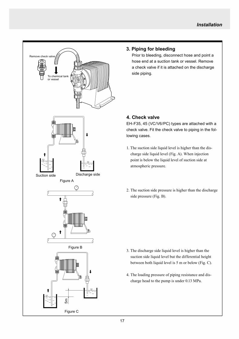
17
Installation
4 Check valveEH-F35 45 (VCV6PC) types are attached with a check valve Fit the check valve to piping in the fol-lowing cases
1 The suction side liquid level is higher than the dis-charge side liquid level (Fig A) When injection point is below the liquid level of suction side at atmospheric pressure
2 The suction side pressure is higher than the discharge side pressure (Fig B)
3 The discharge side liquid level is higher than the suction side liquid level but the differential height between both liquid level is 5 m or below (Fig C)
4 The loading pressure of piping resistance and dis-charge head to the pump is under 013 MPa
Suction side Discharge side
Figure A
Figure B
5m
Figure C
To chemical tankor vessel
Remove check valve
3 Piping for bleedingPrior to bleeding disconnect hose and point a hose end at a suction tank or vessel Remove a check valve if it is attached on the discharge side piping
18
Installation
R12
Oslash12
5 Check valve mounting1 Tap the female thread of NPT12 at an injection
point Check valve is provided with the male thread of R12 Cut off the unused portion to fit it on a pip-ing
2 Apply seal tape on the threaded portion of the check valve and screw it in the injection point Pinch the check valve body lightly with a spanner and tighten it for easy mounting
3 When fitting a hose into a check valve with the check valve on main pipe tighten the fitting nut holding the check valve body by hand
4 Cut the end of check valve(empty 12) accordingly when mounting it in a small pipe It is recommended the end of the check valve comes at the centre of pipe bore
It is recommended to mount a check valve via a valve for maintenance Provide NPT12 female thread and screw it in Valve should be resistant to the chemical liquid in use
Valve
Check valve
Check valve body
Apply seal tape
Fitting nut
Pipe
Cut the end nozzle offif it is too long compared topipe bore
6 Flange connection and union connection1 Flange units and union sockets are packed apart from pump body Fit the flange units or the union sockets to
pump body before use Refer to the following figures2 Secure the sealing by fitting O rings to each connection
CAUTIONWhen mounting flange units or union sockets to pump body be careful not to allow O ring to get out of the groove Especially pay attention to the O ring on the groove on suction side
3 Fix the flange units or the union sockets to the pump body by tightening fitting nuts In this case first tighten the fitting nuts by the hand and then re-tighten it by 90 degrees with a spanner
CAUTION
Fitting nut is made of plastics The fitting nut may break when tightened excessively
Flange connection type
19
Instillation
Flange
Flange
Fitting nut
O ring
O ring
Elbow
Pump body
Fitting nut
Drain
Discharge
Air chamber
7 Accumulator and air chamber mountingInstall an accumulator or an air chamber on piping for the prevention of the vibration from the pulsation of pump discharge hose
20
Installation
8 Piping (General notes)1 Keep piping short and less bends Do not make the projections where air can remains
2 Support piping to avoid having the pump subject to the piping weight especially when wet-end mate-rial is made of PVC
3 In case of transferring the slurry which tends to settle do not make U shape on piping A drain plug is required at the lowest portion of piping as well
4 In case of transferring the viscous or toxic liquid or the liquid which tends to settle provide the piping for cleaning for the purpose of maintenance
5 In case of transferring the high temperature or low temperature liquid the telescopic motion of piping from temperature variation should be taken into consideration
6 Select pipe materials based on a through examination of the corrosive resistance and the estimated pressure applied to piping
7 Do not allow any adhesive agent to get in pump when connecting PVC-made pipe on the discharge side piping
8 Clean the inside of piping before installing pump in it
9 A relief valve is required to protect pump and piping Install a relief valve on the discharge piping near the pump
9 Suction piping1 Regarding suction piping a flooded suction system should be realized The bore of suction piping is
recommended to be larger than that of pump suction port
2 Each joint of suction piping needs to be mounted carefully in order to prevent air from coming in Air influx into piping may cause discharge performance failure and instability
10 Discharge piping1 Mount a relief valve on the discharge piping near pump A discharge valve should be mounted beyond
the relief valve
2 The pressure resistance of discharge piping should be higher than the set pressure of relief valve Mount each joint carefully
21
Installation
4 Electrical wiring
1 Power cord connection
Electrical works and the handling of power source must be done by qualified person
Do not operate pump with the wet hand
Make sure that power is not turned on while working on wirng
Do not dismantle electronic circuit
Electronic circuit may be broken Never apply other voltages than a rated voltage
WARNING
CAUT ION
High power equipment
CAUTION Avoid sharing a power source with a high
power equipment This can lead to the fail-ure of the electronic circuit of control unit due to extremely large surge voltage
The noise from an inverter can cause fail-ure
22
Installation
P
Surge absorption element
PNoise cut transformer
CAUTION
2 Wiring procedure
Electronic circuit of control unit may be failed by extremely large surge voltage Do not use the pump near to the high power equipment of 200V or more which may generate large surge voltage If the use of high power equipment is inevitable take either of the following measuresa Install a surge absorption element such
as varister with 2000A or more durability on the power point
b Install a noise cut transformer
CAUTION
Only qualified operatorsservice staff should be in charge of the related electrical arrange-ment and control of the power source Failure to observe this instruction may result in injury to person or damage to assets
Never connect wires while power is turned on otherwise an electrical shock or a short-circuit of controller may result Be sure to turn off power before wiring
Internal circuit is still electrified right after turning off power Take 1 minute or more to start wiring
Do not band a power cable either electrical wires or relay output wires
Earthing wire is equipped with a jumper pin Keep the jumper pin equipped in use
Do not combine the EXT or STOP signal line with a power cord or a power cable Do not com-bine power source line with the EXT or STOP signal line by a concentric cable (5 wires cable or so) Otherwise noise come about through EXT and STOP wires due to the induction effect from power cable and it may results in wrong operation or the failure of pump
Regarding frequent ON-OFF operation it is recommended to stop pump thorough STOP input terminal but not by connecting or disconnecting power source When connecting and discon-necting power cord can not be avoided it should be within 6 times an hour
23
Installation
Procedure to connect the signal cordUse DIN connector of five poles and four polesThe following connectors made by Binder in Germany are recommendedAsk IWAKI for the detail of Binder connector 5 poles 713 series 99-0436-10-05 for input signal 4 poles 715 series 99-0430-15-04 for level sensor
The following connector made by Hirschmann in Germany is recommendedAsk IWAKI for the detail of Hirschmann connector 4 poles GDS307 for output
The following procedures are based on the connector made by Binder and HirschmannIf a similar connector is used the wiring should be made according to the instruction manual of the manufacturer of connector
In case of Binder connector(1) Dismantle the connector and pass the wire through it Outer diameter of the cable should be oslash4-6
Using the different cable in diameter the connector can not be sealed properly
(2) Strip the cable ends and insert wire to the appropriate positions and connect them with screwsThe maximum allowable cross section of the wire is 075mm2
(3) After connecting the wire assemble the connector securely Slightly pull the cord to confirm that the cord connection is secured Perfect sealing can not be obtained unless the cord connection is loose
24
Installation
In case of Hirschmann connector(1) Dismantle the connector and pass the wire through it Insert a minus screw driver into the place shown by
ldquoLIFTrdquo and lift it up Outer diameter of the cable should be 35-6 mm Using the different cable in diam-eter the connector can not be sealed properly
(2) Strip the cable ends and insert wire to the appropriate positions and tighten them with screwsThe maximum allowable cross section of the wire is 075mm2
(3) After connecting wire assemble the connector securely Slightly pull the cord to confirm that the cord connection is secured Perfect sealing can not be obtained unless the cord connection is loose
Terminal position
NA Not Applicable
Connection of level sensorThe controller corresponds to two stage level sensor Connect the pre-alarm signal to Pre-STOP and the alarm signal to STOP When the pre-alarm signal comes in the orange lamp lights but the pump does not stop When a contact type is used connect wires to STOP and COM2 For open collector output level sensor Pay attention to the polarity Pre-Stop and STOP are plus (+) and COM2 is minus (-) (Max charged voltage 5V Current 18mA) For contact output level sensor Use the one designed for electronic circuit and the minimum applicable load of 1mA or less
Connection inside connector 1 STOP 2 Pre-STOP 3 Free 4 COM2
1
2
3
4 CLOSE
ON
PUMP
Level Sensor(STOP)
OPEN
Pulse
COM
+12VDC
NA
ANA(4-20)
Pre-STOP
STOP
COM
NA
OUT
25
Installation
Stop functionStop function is the function to stop the pump by the external signal Connect the wires to STOP and COM2 in the same way as the level sensor connection
CAUTION
Frequent stop and start of pump should be done by using STOP function (ON and OFF of STOP terminal) If you can not use STOP function and are forced to operate pump by turning OFF and ON of power source ON and OFF of power source should be limited to six times an hour
Pulse signal inputPulse signal input is used when the pump runs in the DIV or MULT of EXT modeDIV means dividing and MULT means multiply In case of open collector signal Pay attention to the polarity Pulse is plus (+) and COM1 is minus (-) (Max charged voltage 5V Current 18mA) In case of contact signal Use the one designed for electronic circuit and the minimum applicable load of 1mA or less
Connection inside connector 1 Free 2 Pulse 3 Free 4 12VDC 5 COM
3
2
4
15
Analog signal inputAnalog signal input is used when the pump runs in ANAR or ANAV of EXT modeANAR means analog rigid and ANAV means analog variable
Connection inside connector 1 ANA 2 Free 3 Free 4 Free 5 COM
3
2
4
15
26
Installation
Output signalOUT Photo MOS relay outputStandard is output synchronous with stroke Output is activated synchronous with each pump stroke
Connection inside connector 1 OUT 4 OUT
OUT 1
2
34
Surge voltage The electronic circuit of the control unit may be affected by excessively high surge voltage Do not operate the pump near the high-power elec-trical equipment of 200V or above that generates high surge voltage Under unavoidable circumstances take either of the following measures(1) Use a surge absorbing element (such as a
varistor with the surge resistance of 2000A or more) at the pump power supply connection
(2) Use a noise-cut transformer
Surge absorbing element
Noise-cut transformer
1 Preparation for pump operationBefore pump operation check that
bull Liquid tank is filled enough Supply liquid if it is less than the required levelbull There is no liquid leakage or congestion due to breakagebull Both suction and discharge side valves are openedbull Pump is connected to the predetermined power source correctlybull Electrical wiring is correct and there is no possibility of a short circuit or current leakage
2 BleedingBleeding is a process to eliminate the air inside the suction-side piping Be sure to carry out an air elimi-nation prior to initiating the pump operation after replacing the liquid inside a tank and after a long peri-od of storage Air gushes together with chemical liquid when carrying our bleeding For safety reasons first turn the end of a bleeding hose to a tank or a container
CAUTION
Some liquids may cause skin trouble or affect the quality of mechanical parts Wipe off chemi-cal liquid immediately when they splash on the hand or mechanical parts
27
Operation
1 Pump Operation
WA R N I N G Wear protective clothing
Wear protective clothing such as a protective mask safety gloves or so when handling chemical liquid
Do not operate pump with a discharge-side valve completely closed Operating the pump with the discharge-side valves fully closed may cause the liquid spillage or
the extremely high pressure inside the pump or the discharge-side pipingtubing This could lead to a piping burst Be sure not to operate pump with the discharge-sides valve closed
CAU T I O N A long time dry running (longer than 30 minutes) may cause the pump overheat and it could lead
to the deformation of the pump unit consists of a pump head and valve cases or so or may loosen the pump head fitting and result in liquid leakage
If the hex socket cap bolts on a pump head are loosened liquid leakage may resultBe sure to fasten all the 6 or 8 hex socket cap bolts tightly before starting the initial pump opera-tion And periodically check the looseness of the bolts on the pump head and retight the bolts as necessary
bull Tightening torque255NbullmTighten all the bolts diagonally applying equal tightness
If electric wiring gets wet due to accidental liquid spillage fire or electrical shock may occur Never get it wet When the electric wiring gets wet turn off power and wipe the liquid away
A frequent ON-OFF operation should be conducted by using STOP function(ON - OFF signals to STOP terminal) In case the STOP function is not available for the ON-OFF operation the ON - OFF operation by turning onoff power should be limited to six times an hour
4
28
3 Procedure for bleeding
Check valve should be removed
To tank or drain pan
100
75
50
25
0 25 50 75 100
(Fixed stroke length)
Stroke length adjustment
240spm
180spm
120spm
Flow
rate
Operation
[1] Extend the tube connected to the discharge-side fitting nut of pump to a chemical tank or a drain pan Then start pump operationbull Remove a check valve if it is installed on dis-
charge-side
[2] Operate the pump for about 10 minutes to eliminate air completely
[3] When the air in pump head is completely eliminated and liquid is replaced return the discharge-side tube to the regular tubing position
[4] Finally make sure there is no leakage in any section
4 Discharge capacity adjustmentDischarge capacity can be adjusted by both the stroke length adjustment and the stroke rate adjust-ment but basically adjust it via the stroke rate adjustment Stroke length adjustment is an auxiliary way to cover the range where the stroke rate adjustment can not reachPay attention to the following for correct procedure
Stroke rate adjustment(1) For some liquids which diffuses gas such as sodium hypochlorite and hydrazine solution adjust discharge capac-
ity by means of the stroke rate adjustment with the stroke length about 100 Gas lock may occur if the stroke length is set to short
(2) When the back pressure on discharge side is high adjust discharge capacity by the stroke rate adjustment with the stroke length about 100
(3) In case reaction is greatly influenced depending on the discharge capacity per pump shot in the application of neutralization or titration adjust discharge capacity by the stroke rate adjustment with the shortened stroke length and reduce the discharge capacity per shot
1 Discharge capacity adjustment procedureAppropriate stroke length and stroke rate are decided on the pump operating condition and liquid characteristics Following ways are recommended for proper calibration
(1) Set stroke length at 100 and roughly adjust discharge capacity by adjusting stroke rate
(2) Measure discharge capacity(3) If the measured capacity is below the wanted value
increase the stroke rate and measure again the dis-charge capacity
(4) Adjust stroke length for the fine adjustment of discharge capacity(5) Determine a discharge capacity at the last and confirm the wanted capacity is discharged
CAUTION
29
100
75
50
25
0 60 120 180 240spm
Fixed stroke length
Stroke rate adjustment
Flow
rate
Screw driverOPEN
LOCK
100
75
50
25
0 25 50 75 100
Fixed stroke rate
Flow
rate
Stroke length adjustment
Operation
2 Stroke rate adjustmentStroke rate is adjusted by the key operations of control unit Control the plunger stroke rate per minute from 1 to 240 spm via control unit
3 Stroke length adjustmentStroke length adjustment knob is locked with a screw Loosen the screw before adjustment and lock it afterwards
(1) Turn on pump and adjust the discharge capacity by turning the stroke length adjusting knob while pump is running
(2) The left graph shows the relation between stroke length and discharge capacity The maximum dis-charge capacity is shown on the name plate
bull The usage between 40 and 100 is practi-cal
Do not turn the stroke length adjusting knob when pump stops
CAUTIONBe sure to tighten the screw on the adjust-ment knob after an adjustment The knob may rotate unintentionally due to a loose fixation This may result in the fluctuation in a discharge rate
30
Mode ParameterDefault value
Setting range Step
Manual operation Stroke speed 240 1-240DIV setting Dividing ratio frasl 1 1-9999
MULT setting Multiply ratio times1 times1-9999ANA R setting 4-20 4-20 20-4 0-20 20-0
ANA V setting
P1 amperage 40 00-200P1 stroke speed 0 0-240P2 amperage 200 00-200P2 stroke speed 240 0-240
User setting
EXT operation ANA V DIV MULT ANA R ANA V
Anti-chatteringMECH MECH ELECST05 ST05 ST20 ST50FT01 FT02 FT04
Buffer memory MEM-N MEM-N MEM-Y
111-
011
011
2 Control unit operationEH-F type pump is controlled by means of setting or changing the setting values of the controller Control functions are various at each operation mode Read this section carefully before operation
Default parameter values
5 Full operationPut pump in use after bleeding and adjusting discharge capacityPump runs in manual operation or in accordance with the setting of control unit
6 Manual operationStarting pump After turning on power ON lamp (Green) appears and display shows WAIT mode For
the first time to turn on power MAN lamp appears and pump starts after pushing STARTSTOP key once
Stop pump Push STARTSTOP key to turn off MAN lamp and stop pump Pump starts and stops every time STARTSTOP key is pressed
7 EXT operationRefer to the next section of 2 Control unit operation
8 Shout down When pump will not in use for a long time (one month or more)
Run pump with clean water about 30 minutes in order to clean the wet-end parts and the inside of pip-ing before storage
When re-starting pump after a long time storage If pump dose not suck up liquid clean valve sets and remove the sticking foreign matters Carry out an air elimination and adjust discharge capacity when air stays inside pump head Refer to page 28 3 Procedure for bleeding
Operation
---
-
31
AN
A V
(Ana
log
var
iabl
e)
DIV
(Pul
se d
ivid
ing)
MU
LT(P
ulse
mul
tiply
)A
NA
R(A
nalo
g ri
gid)
SE
TS
ET
Use
r mod
e
EX
T m
ode
sele
ctio
n
EX
T
EX
TE
XT
EX
TE
XT
EX
T EX
T
EX
T
EX
T
EX
T
EX
T
EX
T
EX
T
EX
T
EX
T
EX
T
EX
T
EX
T
3 sec
onds
or m
ore
Wai
t mod
e
Set
ting
of fi
xatio
n pa
ttern
EX
T m
ode
Man
ual o
pera
tion
Set
ting
of s
troke
num
ber
AN
A R
(Ana
log
rigi
d)M
ULT
(Pul
se m
ultip
ly)
DIV
(Pul
se
div
idin
g)
AN
A V
(Ana
log
var
iabl
e)
anti-
chat
terin
gse
tting
dis
play
Setti
ng o
f div
idin
g ra
tioS
ettin
g of
cou
nt n
umbe
r
Curre
nt va
lue of
P1
Stro
ke nu
mbe
r of P
1
Curre
nt va
lue
of P
2
Stro
ke nu
mbe
r of P
2
EX
T O
pera
tion
Dis
play
EX
T se
tting
mod
e
Buf
fer m
emor
yse
tting
dis
play
Pow
er O
N
spm
MA
Nsp
m
spm
DIV
DIV
SE
TS
ET
MU
LT
MU
LTsp
mA
NA
V
spm
AN
AR
AN
AR
SE
Tm
AS
ET
mA
spm
AN
A
V
P1
mA
SE
T
spm
AN
A
V
P1
AN
AR
SE
Tm
A
AN
AR
SE
Tm
AS
ET
AN
A
V
P 2
SE
T
spm
AN
A
V
P 2
AN
AR
SE
Tm
A
AN
A
V
SE
TS
ET
SE
T
SE
T
SE
T
SE
T
SE
T
SE
T
SE
T
SE
T
SE
TS
ET
1 Overview Operating Scheme
Operation
1 means automatic transfer WAIT mode is selected when the power is switched on for the first time On and after the initial power activation pump restores the previous status right before the power is switched off
2 Regarding MANUAL mode pump starts operation by pushing STARTSTOP key at WAIT modePushing STARTSTOP key again the pump stops and returns to WAIT mode
3 Regarding EXT operation pushing EXT key at WAIT mode the pump moves to EXT mode and starts operationPushing STARTSTOP key stops the operation and returns the pump to WAIT mode
4 The change of each setting of EXT operation is accessible by pushing EXT key at EXT mode Pushing EXT key after the setting pump starts in EXT operation according to the changed setting
5 Pushing EXT key for 3 seconds at WAIT mode pump moves to USER mode At USER mode the EXT mode selection and the detailed setting such as the setting of buffer memory or so can be obtained
For details refer to each section of 2 Pump operation
2 Pump operation1 Operation of controller
Before turning on power confirm the specified power source on the nameplate
CAUTION
Connecting any other powers than the one shown on nameplate to pump is strictly prohibitedIt could lead to pump trouble or failure
Operation
32
1 Turning on powerDisplay shows WAIT mode when pump is turned on for the first time After the initial power activation the pump restores the previous mode right before the power was turned off last time If power is turned off at any setting modes WAIT mode appears at the next power activation
Stroke speed setting value is shown on display at WAIT mode ON lamp lights (Green)
EXT
EH-F ControllerSTARTSTOP
ON STOP
spm
33
2 Manual operation(1) Stroke speed can be adjusted by and
keys The figure changes quickly when either or key is depressed The picture below
shows the stroke speed is set to 160 spm
EXT
EH-F ControllerSTARTSTOP
ON STOP
spm
EXT
EH-F ControllerSTARTSTOP
ON STOP
MAN spm
EXT
EH-F ControllerSTARTSTOP
ON STOP
spm
(2) Push STARTSTOP key once to start the pump operation MAN indication appears and ON lamp blinks synchronously with each stroke
(3) MAN indication disappears and ON lamp stops blinking as STARTSTOP key is pushed again Pump enters WAIT mode
Operation
Operation
34
EXT
EH-F ControllerSTARTSTOP
ON STOP
ANA V
P1 SET mA
EXT
EH-F ControllerSTARTSTOP
ON STOP
P1 SET
ANA V spm
EXT
EH-F ControllerSTARTSTOP
ON STOP
spm
EXT
EH-F ControllerSTARTSTOP
ON STOP
ANA V spm
(4) Set the current value at P1 Figure increases or decreases as or key is pushed The pic-ture below shows 80 mA is set to point 1
EXT
EH-F ControllerSTARTSTOP
ON STOP
ANA V
P1 SET mA
(5) Pushing EXT key once spm appears on the display while mA disappears The picture below shows the number of strokes at P1
EXT
EH-F ControllerSTARTSTOP
ON STOP
P1 SET
ANA V spm
3 EXT operation (ANA V mode)(1) Push STARTSTOP key to move to WAIT mode
if pump is in another mode Go to next step if pump is in WAIT mode
(2) ANAV indication appears and pump enters an EXT mode as EXT key is pushed once Pump starts operation in accordance with current sig-nals and various settings ON lamp blinks at each pumping during operation Pump is con-trolled via the EXT mode which was select-ed at USER mode The initial setting of EXT mode is ANA V mode Select a preferable EXT mode in USER mode The picture below shows ANA V mode (The spm on the display changes according to input signals)
(3) Push EXT key once when pump is running in ANA V mode Display indicates the setting display of ANA V mode spm indication dis-appears and P1 SET and mA indications appear on the screen
(6) Set the number of strokes at P1 Figure increasesdecreases as key is pushed Picture below shows 10 spm is set for point 1
Operation
35
(7) Push EXT key to move to the setting display of the current value at P2 P1 and spm disap-pear and P2 and mA appears instead
EXT
EH-F ControllerSTARTSTOP
ON STOP
ANA V
P 2 SET mA
EXT
EH-F ControllerSTARTSTOP
ON STOP
ANA V
P 2 SET mA
EXT
EH-F ControllerSTARTSTOP
ON STOP
P 2 SET
ANA V spm
(11) Push EXT key to return to EXT mode Pump starts to run in ANA V mode on the setting of (4) through (10) ON lamp starts to blink at each pumping
EXT
EH-F ControllerSTARTSTOP
STOPON
ANA V spm
EXT
EH-F ControllerSTARTSTOP
ON STOP
P 2 SET
ANA V spm
EXT
EH-F ControllerSTARTSTOP
ON STOP
spm
(8) Set the current value of P2 by pushing and keys Picture below shows 180 mA is set to
point2
(9) Pushing EXT key once spm appears on the display while mA disappears The picture below shows the number of strokes at P2
(10) Set the number of strokes at P2 by pushing and keys Picture below shows 200
spm is set to point 2
(12) Pushing STARTSTOP key pump enters WAIT mode and pump stops ON lamp stops blink-ing and ANAV indication disappears
CAUTIONWhen the setting of the buffer memory is OFF keep the number of strokes in the dividing operation 240 spm or below The input signals to operate the pump over 240 spm can cause an unstable pump operationWhen the setting of the buffer memory is ON the pump operates for all the input pulse signalsPump keeps operating after all the signals are stopped in this case Be careful when setting of buffer memory
Operation
36
EXT
EH-F ControllerSTARTSTOP
ON STOP
DIV
SET
EXT
EH-F ControllerSTARTSTOP
ON STOP
DIV
SET
EXT
EH-F ControllerSTARTSTOP
STOPON
DIV spm
EXT
EH-F ControllerSTARTSTOP
ON STOP
spm
(2) Pushing EXT key DIV appears and pump starts operation in the ratio of input pulse sig-nals a pumping ON lamp blinks synchronous-ly at each pumping The initial setting of EXT selection is ANA V mode Change mode to DIV mode via USER mode Refer to P 40 for detail information
(3) Push EXT key while pump is operating in DIV mode Pump stop running and SET indication appears on the DIV setting display in stead of spm indication
(4) Enter a dividing ratioFigure increasesdecreases when key is pushed The picture below shows 10 is set
4 EXT operation (DIV mode)
(1) Push STARTSTOP key to move to WAIT mode if pump is in another mode Go to next step if pump is in WAIT mode
CAUTIONOn condition the setting of buffer memory is OFF do not input any pulse signals during the pumping motions for a input pulse signal in the multiply operation These input pulse signals are cancelledWhen the setting of buffer memory is ON pump operates for all the input pulse signals
Operation
37
EXT
EH-F ControllerSTARTSTOP
ON STOP
spm
EXT
EH-F ControllerSTARTSTOP
STOPON
DIV spm
EXT
EH-F ControllerSTARTSTOP
ON STOP
spm
EXT
EH-F ControllerSTARTSTOP
ON STOP
MULT
(5) Push EXT key to return to EXT operating mode Pump starts to run on the setting at item (4) ON lamp blinks synchronously at each pumping
(6) Pushing STARTSTOP key pump enters WAIT mode and pump stopsDIV indication disappears and ON lamp stops blinking
5 EXT operation (MULT mode)
(2) MULT indication appears and pump starts running in an EXT operation mode in the ratio of an input pulse signal pumpings as press-ing EXT key ON lamp blinks at each pump-ing Display shows the rest of the number of strokes In MULT mode the number of strokes is equal to the setting value in manual opera-tionThe initial setting of the EXT mode selection is ANA V mode which is the operation in pro-portion to current First select MULT mode via USER mode Refer to P 40 for detail informa-tion
(1) Push STARTSTOP key to move to WAIT mode if pump is in another mode Go to next step if pump is in WAIT mode
Operation
38
EXT
EH-F ControllerSTARTSTOP
ON STOP
spmEXT
EH-F ControllerSTARTSTOP
ON STOP
ANAR spm
EXT
EH-F ControllerSTARTSTOP
ON STOP
MULT
SET
EXT
EH-F ControllerSTARTSTOP
ON STOP
MULT
EXT
EH-F ControllerSTARTSTOP
ON STOP
spm
EXT
EH-F ControllerSTARTSTOP
ON STOP
MULT
SET
(5) Push EXT key to return to MULT mode(3) Pushing EXT key when pump is running in the multiply operation calls the setting display of MULT mode and SET indication appearsPump stops running and ON lamp stop blinking
(4) Enter the number of pumpings per input signalFigure increasesdecreases when key is pushed The picture below shows the pump-ing number is set to 1800 times per an input signal
6 EXT operation (ANA R mode)(1) Push STARTSTOP key to move to WAIT mode
if it is in another mode Go to next step if it is in WAIT mode
(6) Pushing STARTSTOP key recalls WAIT mode and pump stops spm indication appears in stead of MULT indication
(2) Pushing EXT key ANAR appears and pump starts running in the ratio of an input pulse sig-nal pumpings ON lamp blinks at each pump-ing The initial setting of the EXT mode selec-tion is ANA V mode which is the operation in proportion to current is selected First select ANA R mode in USER mode Refer to P 40 for more information
Operation
39
EXT
EH-F ControllerSTARTSTOP
ON STOP
ANAR
SET mA
EXT
EH-F ControllerSTARTSTOP
ON STOP
ANAR spm
EXT
EH-F ControllerSTARTSTOP
ON STOP
ANAR
SET mA
EXT
EH-F ControllerSTARTSTOP
ON STOP
spm
(4) Figure increasesdecreases when key is pushed The picture below is when it is set to 0-240 spm for 20-4 mA
(5) Push EXT key to return to EXT mode Pump starts to run on the setting at item (4) ON lamp blinks synchronously at each pumping
(6) When pushing STARTSTOP key pump enters WAIT mode and stops running ON lamp stops blinking and ANAR disappears
(3) Pushing EXT key when pump is running in the multiply operation calls the setting display of ANAR mode and SET and mA indications appear while spm disappears Pump stops running and ON lamp stops blinking
Operation
40
EXT
EH-F ControllerSTARTSTOP
ON STOP
ANA V
(5) Push EXT key to confirm the desired EXT mode Pump displays the EXT mode selection The picture below shows DIV appears to indi-cate DIV mode is selected
EXT
EH-F ControllerSTARTSTOP
ON STOP
DIV
EXT
EH-F ControllerSTARTSTOP
ON STOP
SET
EXT
EH-F ControllerSTARTSTOP
ON STOP
spm
EXT
EH-F ControllerSTARTSTOP
ON STOP
spm
EXT
EH-F ControllerSTARTSTOP
ON STOP
SET
7 USER settingThe setting of each function is changed in USER mode Have the pump entering WAIT mode in order to move to USER mode OUT (Output) is synchronous with spm and it can not be changed
7-1 EXT mode selection Any one of DIV (pulse dividing) MULT (pulse multiply) ANAR (analog rigid) or ANAV (analog vari-able) can be active in EXT mode The initial mode when shipped from factory is ANAV
(1) Push STARTSTOP key to move to WAIT mode if it is in another mode If it is in WAIT mode go to next step
(2) Press EXT key for more than 3 seconds to move to USER mode The picture below shows pump enters the EXT mode selection
(3) Pushing EXT key SET appears and display shows the mode currently set Picture below shows ANA V mode is selected
(4) Push or key to select a desired EXT mode The picture below shows DIV mode is selected
(6) Push STARTSTOP key to move to WAIT mode spm appears while DIV goes out
Operation
41
EXT
EH-F ControllerSTARTSTOP
ON STOP
spm
EXT
EH-F ControllerSTARTSTOP
ON STOP
ANA V
EXT
EH-F ControllerSTARTSTOP
ON STOP
SET
(3) Push key once
EXT
EH-F ControllerSTARTSTOP
ON STOP
(4) Push key again to move to the anti-chatter-ing setting display
EXT
EH-F ControllerSTARTSTOP
ON STOP
(5) Pushing EXT key display shows the mode cur-rently set and SET appears on it The picture below shows when MECH is selected
EXT
EH-F ControllerSTARTSTOP
ON STOP
SET
7-2 Setting of anti-chattering Anti-chattering function is settable against the incoming pulses during the DIV or MULT operation For the long chattering of mechanical contact such as relay set a large figure via MECH For the high speed (high frequency) chattering of the semi-conductor type contact such as transistor set a small figure via ELEC ST05 of MECH is initial setting
(6) Select MECH by or key for a mechani-cal contact And select ELEC for a semi-conductor contact The picture below shows ELEC is selected
(1) Push STARTSTOP key to move to WAIT mode if it is in another mode If it is in WAIT mode go to next step
(2) Press EXT key for more than 3 seconds to move to USER mode The picture below shows pump enters the EXT mode selection
Operation
42
EXT
EH-F ControllerSTARTSTOP
ON STOP
SET
(7) Push EXT key to display the current set state The picture below shows FT01 is selected
EXT
EH-F ControllerSTARTSTOP
ON STOP
SET EXT
EH-F ControllerSTARTSTOP
ON STOP
EXT
EH-F ControllerSTARTSTOP
ON STOP
spm
7-3 Setting of buffer memoryIn case pump operation can not catch up with the input pulse signals in DIV or MULT operation exces-sive pulse signals can be put in memory up to 65535 pulses However the excessive pulses can not be restored if once power is off or mode is changed
EXT
EH-F ControllerSTARTSTOP
ON STOP
spm
(2) Press EXT key for 3 seconds or more to move to USER mode The picture below shows the EXT mode selection display
EXT
EH-F ControllerSTARTSTOP
ON STOP
ANA V
(8) Set a large figure for the long chattering by or key and set a small figure for high speed (high frequency) chattering The picture below shows FT04 is selected
(9) Push EXT key to return to the anti-chattering setting display SET indication disappears
(10) Push STARTSTOP key to return to wait mode spm indication appears
(1) Push STARTSTOP key to move to WAIT mode if it is in another mode If it is in WAIT mode go to next
Operation
43
(3) Push key once
EXT
EH-F ControllerSTARTSTOP
ON STOP
(7) Push or key in order to set buffer memo-ry to ON or OFF Select MEM-Y to set it ON Select MEM-N for OFF setting The picture below shows when ON is set
EXT
EH-F ControllerSTARTSTOP
ON STOP
SET
(4) Push key once again
EXT
EH-F ControllerSTARTSTOP
ON STOP
(8) Push EXT key to return to the buffer memory setting display SET indication disappears
EXT
EH-F ControllerSTARTSTOP
ON STOP
(9) Push STARTSTOP key to return to WAIT mode spm indication appears
EXT
EH-F ControllerSTARTSTOP
ON STOP
spm
(5) Push key once again and the buffer memory setting display is shown
EXT
EH-F ControllerSTARTSTOP
ON STOP
(6) Push EXT key in order to display the current set state SET indication appears The picture below shows the buffer memory is set to OFF
EXT
EH-F ControllerSTARTSTOP
ON STOP
SET
Operation
44
8 Bleeding amp self-primingAt WAIT mode Manual operating mode and EXT operating mode pump operates at max speed tak-ing priority over any functions when both and keys are pushed at once Pump runs at max speed only when both keys are depressed Pump state returns to the previous mode once either or key is released Pressing and keys for 10 seconds keeps pump running at maximum speed In this state this fixation is released when pushing either or key once and pump returns to the previous mode
(1) When pump is running in ANAV mode
EXT
EH-F ControllerSTARTSTOP
ON STOP
ANA V spm
(2) Pump start to run at full speed when and keys are pressed at once Display shows
PRIME If either or key is released pump returns to the previous mode In this case pump returns to ANAV mode
EXT
EH-F ControllerSTARTSTOP
ON STOP
ANA V
(3) Pressing both and keys simultaneously for 10 seconds or more pump continues to run at full speed even if both keys are released In this case indication appearsPush either or key to release this state indication disappears and pump returns to the previous mode In this case pump returns to ANAV mode
EXT
EH-F ControllerSTARTSTOP
ON STOP
ANA V
Operation
45
10 Error display and release(1) In case Input signals fall to 4 mA or below while
4-20 or 20-4 is set to ANA R mode pump stops with DISCN blinking and Err on dis-play
(2) This error state can be released by push-ing STARTSTOP key and pumps enters wait mode In this case check the wiring and input signals
EXT
EH-F ControllerSTARTSTOP
ON STOP
ANAR
Err
spm
EXT
EH-F ControllerSTARTSTOP
ON STOP
spm
9 Key lockKey lock function is to prevent pump from being operated by some other person than user If STARTSTOP key is pressed for five seconds or more when pump is running or stops all key operations become ineffective with LOCK indication on display This function can be released by pressing STARTSTOP key for 5 seconds while LOCK lights
EXT
EH-F ControllerSTARTSTOP
ON STOP
MAN spm
LOCK
46
Do not conduct a maintenance work with the wet hands It can cause an electric shock
Before dismantling pump be sure to turn off power and check the pump is not electrified Do not
start a dismantlement work after stopping the pump by pushing the STARTSTOP key only Put up
the sign of ldquoMaintenance work is in progressrdquo in order to prevent a pump switch from turning on
unintentionally during the work Release the pressure of discharge piping and drain the liquid from
the wet end parts And then clean the inside of pump head
Wear protective clothing such as a protective mask globes goggles and chemical-proof wear
according to the handled chemical liquid during the work
WARNING
5 Maintenance
1 Trouble shootingTrouble Cause Troubleshooting
Pump dose not start Faulty wiring or disconnection in wiring Voltage is too low Failure in the electronic circuit of control unit
Pump dose not suck liquidDischarge amount is low
Air suction from suction piping Valve gasket is not installed Valve set assembling direction is wrong Pump is air-locked Pump stroke length is too short Suction-sidedischarge-side valve is clogged with
foreign matter Adhesion of valve onto valve seat
Discharge amount fluctuates
Liquid leaks
Key operation is ineffective Key is locked Release key lock
Pump doesnt run
Pump is in waiting mode Signals are not coming for EXT operation Pump is in EXT setting mode Pump is suspended with STOP
Move to operation mode Check wiring and correct the wrong part Move to EXT operating mode Release STOP function
Abnormal noise
Suction-sidedischarge-side valve is clogged with foreign matters
The sound absorption gasket is worn out Bearing is worn out Spring is damaged
Piping vibrates due to pulsation Bearing is worn out Spring is damaged
Install a accumulator or an air chamber The end of pump life span The end of pump life span
Suction-sidedischarge-side valve is clogged with foreign matters
Air is trapped in pump Overfeeding Diaphragm is damaged
Fittings are not tightly closed Pump head is not tightened Diaphragm is damaged O ring and valve gasket are not installed O ring is damaged
Correct wiring Inspect power source and provide measurement Replace the whole unit
Arrange piping again Install valve gasket Reassemble valve set Carry out air elimination Drive pump with 100 stroke length to prime liquid Then
reset stroke length Disassemble inspect and clean Disassemble inspect and clean
Tighten fittings Tighten pump head Replace diaphragm Install O ring and valve gasket Replace O ring
Disassemble inspect and clean
Carry out air elimination Install a check valve or a back pressure valve Replace diaphragm
Disassemble inspect and clean
The end of pump life span The end of pump life span The end of pump life span
Abnormal vibration
Input pulse can not be read Signals are not coming Anti-chattering setting is not proper
Check wiring and correct the wrong part Change the setting properly
Analog signal input can not be read
Wrong wiring Signals are over acceptable loaded resistance
Check wiring and correct wrong part The load resistance is 200Ω Use some devise which can
accept the load resistance
47
CAUTION Check periodically whether the bolts fixing pump head are tightened Tighten them as needed
The bolts fixing pump head may loosen in operation Tightening torque 255Nbullm
Maintenance
3
bull Tighten joint where leakage has occurredbull The excessive air bubbles in the discharged liquid mean air suc-
tion has been caused in system Examine the piping and tighten joint on where leaks
Is there liquid leakage or air suction at any joints on pump or piping
2 Maintenance and inspection
1 Daily inspectionPay attention to the following points during pump operation Stop pump immediately upon detecting abnormality and take measures according to the item Troubleshooting When wear parts come to the life time replace them by new ones
No
1
2
Check Point Description
Does pump lift liquid normally
bull Is liquid normally fedbull Is suction pressuredischarge pressure at normal levelbull Has liquid undergone quality change crystallization or solidifica-
tion
Abnormal noise or vibrationbull Abnormal noise or vibration may happen from the abnormal func-
tioning of pump
EXT setting can not be stored
After EXT setting STARTSTOP key is pushed for EXT by mistake
Push EXT key to operate pump in EXT mode
ldquoPRIME is kept indicated and other operations are inac-cessible
Self-priming function is active Push either or key to release the function
Analog signal input can not be read and DISCN indication appears
Wrong wiring or disconnection Check wiring and correct the wrong part Refer to page 45
for how to release an error indication
Trouble Cause Troubleshooting
48
Maintenance
2 Wear partsWear parts should be replaced in proper period for a long period of pump operation It is recommended that follow-ing parts are always ready for the replacementVC V6 PC P6 types
Parts Qty Life span
Pum
p he
ad
Valve set
EH-F35 EH-F45 EH-F55middot70
2sets
8000hours
Diaphragm 1
Refer to exploded view
Bac
k pr
essu
re v
alve
1
2
Che
ck v
alve
7 6 1
8 11 1
Diaphragm seat 1
O ring
Poppet check valve (With check gasket)
Check valve spring Spacer
Diaphragm
O ring
Note Durability of wear parts depend on the pumped liquid temperature and pressure Time to be replaced mentioned as above is the estimation obtained by continuous pump-ing of clean water at ambient temperature
8000hours
4000hours
49
3 Dismantlement and assembly
Getting wet with or coming in contact with chemicals and toxic liquid is harmful Wear protective clothing such as a protective mask globes goggles and chemical-proof wear during the work
Risk of electrical shock Be sure to turn off power and confirm that pump and devices are not electrified before the work
Release the pressure inside pump and a discharge hose by opening an air bleed valve on piping prior to loosening the piping connections or the dismantlement of pump Dismantlement with the pressure inside pump could lead to liquid spillage
Be careful not to touch residual liquid when dismantling pump Some liquids are harmful for skin or component parts Wipe off liquid when the hand or the component parts come in contact with liquid
WARNING
CAUT ION
Hose
Hose stopperFitting spacer
O ring
Fitting nut
Fitting
Pumphead
Remove the fittingwith a spanner
1 Valve set replacement Dismantlement1 Loosen a fitting nut and remove the hose con-
nected to pump head Pay attention to the liquid dripping
2 Loosen a fitting with a spanner to remove it Then detach the valve set from pump head
Maintenance
50
AssemblyAssembly procedure is in reverse order to disas-sembly Pay attention to the following when assembling valve set DispositionInsertion direction of valve set The wrong dispositioninsertion direction of valve
set component can lead to leakage and less dis-charge amount
O ring is fitted properly1 Discharge side valve set mounting
Put valve set in pump head and screw a fitting into a pump head by hand and then re-tighten it by 14 turns with a spanner
2 Suction side valve set mountingPut valve set in connection port and screw the fitting into pump head by hand and then re-tighten it by 14 turns with spanner
Note Pay attention to the mounting direction of the spacer fitted to EH-F45(VC V6 PC)Make sure the cut portion on the spacer of suction side should be downward the one of discharge side should be upward
Suction side
Discharge side
O ringValve gasket
Valve gasket
Valve gasket
Valve guideValveValve seatSpacer
O ring
Valve gasketValve guideValveValve seat
Spacer
1714
11
1312
11
1312
17
17
14
14
14
11
31
1312
31
17
14
11
1312
12
13
11
14
EH-F35
EH-F45
EH-F5570
Suct
ion
side
Dis
char
ge s
ide
For b
oth
suct
ion
and
disc
harg
e si
deFo
r bot
h su
ctio
nan
d di
scha
rge
side
VC V6 PC P6 Type
Maintenance
51
Pay attention not to lose diaphragm spacer and to apply the correct number of diaphragm spacers 0 to several pieces of diaphragm spacers are put between retainer and plunger to adjust the position of diaphragm The number of spacers mounted depends on the pump model There are the models which do not have spacers
Maintenance
2 Diaphragm replacement Dismantlement1 Set stroke length to 0 by adjusting stroke length
adjustment knob
2 Remove the pump head from the pump body by loos-ening hex socket cap bolts
3 Rotate a diaphragm anti-clockwise to remove it from a plunger pin The diaphragm is screwed into the plunger pin
AssemblyAssembly is done in reverse order to disassembly Follow the steps below1 Make sure the stroke length of pump is set to 0
prior to an assembly Operate pump to set the stroke length to 0 and
stop it Then turn off power
2 Fit a rear diaphragm seat a retainer and a diaphragm spacer into new diaphragm via the threaded pin and screw the diaphragm into the plunger pin
Fit the concave side of retainer into the convex side of diaphragm Pay attention the retainer dose not come off
3 Set the stroke length to 100 Operate pump to set the stroke length to 100
and stop it Then turn off power4 Install a pump head to a pump body by tightening
the hex sock cap bolts equally Tightening torque is 255Nbullm
52
4 Accessories1 Connection port bore bull Check valve bull Back pressure valve
Note1 Check valves and back pressure valves are options2 Regarding the connection of the discharge side of back pressure valve
NPT38 and NPT12 taper pipe thread is used for BV-N-CR
Pump type Connection port bore Check valve Back pressure valve
EH-F35VC empty38timesempty12 hose CA-3VCH-C6 ndash
empty38timesempty12 hose CA-3VEH-C6 ndashempty38timesempty12 hose CA-3VH-C6 ndashempty38timesempty12 hose CA-3VCH-C6 ndashempty38timesempty12 hose CA-3VEH-C6 ndashempty38timesempty12 hose CA-3VH-C6 ndash
V6
empty38timesempty12 hose ndash BV-3NV-C6Rempty38timesempty12 hose ndash BV-3NE-C6Rempty38timesempty12 hose ndash BV-3NPV-C6Rempty58timesempty34 hose ndash BV-3NV-C7Rempty58timesempty34 hose ndash BV-3NE-C7Rempty58timesempty34 hose ndash BV-3NPV-C7R
PC
EH-F45VCV6PC
EH-F55VCV6PC
EH-F70VCV6PC
Maintenance
53
Maintenance
5 Exploded view
1 General view The extent of dismantlement is within the following exploded view
Diaphragm spacer
Retainer
(Back up retainer)55 bull 70 types
Pump body
Valve set
Valve set
Pump head
Diaphragm
Rear diaphragm sheet
54
2 Pump head (Hose connection type)
EH-F45 type EH-F35 type
4
28
2930
3
1114
131211
131217
1897
1
17
111312111312
3
3029
28
4
1920
1920 21
17
111312
31
3
3029
28
4
131217
189
7
11
3114
14
4
282930
3
1
21
1515
EH-F55 type
4
28
2930
3
11
131217
18
9
7
10
1
1920 21
17
111312
3
30
29
28
4
EH-F70 type
4
28
2930
3
14
11131217
18
9
7
10
1
1920 21 17
111312
3
30
29
28
4
15 15
14
1414
14
14 14
Note1 The back up retainer of No10 is only for EH-F55 bull 70 typesNote2 The figure inside ( ) in the above table is for EH-F45 bull 55 bull 70 typesNote3 The number of the diaphragm spacers (No18) is not constant None or a few spacers is inserted at
each diaphragmNote4 The figure inside ( ) in the above table is for EH-F70Note5 EH-F35 bull 55 bull 70 (VC V6 PC ) types require 2 valve gaskets and EH-F45 (VC V6 PC) types
require 4 of themNote6 The spacer on No31 is for EH-F45 type only
No Name Qty1 Pump head 13 Fitting 24 Fitting nut 27 Diaphragm 19 Retainer 110 Back up retainer 1 Note111 Valve guide 4 (2) Note212 Valve seat13 Valve14 Valve gasket
No Name Qty
17 O ring 218 Diaphragm spacer 1 Note319 Hex socket head bolt 6 (8) Note420 Spring washer21 Plain washer28 Hose stopper 229 Fitting spacer 230 O ring 231 Spacer 2 Note6
15 Rear diaphragm seat 1
2 (4) Note54 (2) Note24 (2) Note2
6 (8) Note46 (8) Note4
Maintenance
55
Maintenance
3 Pump head (Flange connection type) EH-F55 type
30
3
11
131217
18
9
7
10
1
1920 21
17
11
1312
3
30
EH-F70 type
15
EH-F45 type EH-F35 type
30
3
11131211
131217
1897
1
17
11131211
1312
3
30
1920
1920 21
17
111312
31
3
131217
189
7
11
31
30
3
1
30
21
1515
30
3
11131217
18
9
7
10
1
1920 21 17
11
1312
3
30
15
32
33
33
32
4
32
433
43332
32
334
43332
32
33
32
334
44
1414
14 14 14
1414
14
14 14
NoNo Name Qty1 Pump head 13 Fitting 24 Fitting nut 27 Diaphragm 19 Retainer 110 Back up retainer 1 Note111 Valve guide 4(2)Note212 Valve seat 4(2)Note213 Valve 4(2)Note214 Valve gasket 2(4)Note5
Name Qty
17 O ring 218 Diaphragm spacer 1 Note319 Hex socket cap bolt 6(8)Note420 Spring washer 6(8)Note421 Plain washer 6(8)Note430 O ring 2
33 Union 2
31 Spacer 2 Note6
15 Rear diaphragm seat 1
32 Flange 2
Note1 The back up retainer of No10 is only for EH-F55 bull 70 typesNote2 The figure inside ( ) in the above table is for EH-F45 bull 55 bull 70 typesNote3 The number of the diaphragm spacers (No18) is not constant None or a few spacers is inserted at
each diaphragmNote4 The figure inside ( ) in the above table is for EH-F70Note5 EH-F35 bull 55 bull 70 (VC V6 ) types require 2 valve gaskets and EH-F45 (VC V6) types require 4 of
themNote6 The spacer on No31 is for EH-F45 type only
56
4 Pump head (Flange connection horizontal suction port type) EH-F55 type
30
3
11
131217
18
9
7
10
1
1920 21
17
111312
3
30
EH-F70 Type
15
EH-F45 Type EH-F35 type
30
3
11131211
131217
1897
1
17
111312111312
3
30
1920
1920 21
17
11131231
3
131217
189
7
11
31
30
3
1
30
21
1515
30
3
11131217
18
9
7
10
1
1920 21 17
111312
3
30
15
32
33
32
433
43334
32
32
334
43334
32
33
44
34
32
334
34
32
334
32
35 353535
1414
14 14 14
1414
14
14 14
No Name Qty1 Pump head 13 Fitting 24 Fitting nut 27 Diaphragm 19 Retainer 110 Back up retainer 1 Note111 Valve guide 4 (2) Note212 Valve seat13 Valve
15 Rear diaphragm sheet 114 Valve gasket
No Name Qty
18 Diaphragm spacer 1 Note319 Hex socket cap bolt20 Spring washer21 Plain washer
31 Spacer 2 Note6
35 Pipe 1
32 Flange 2
34 Elbow 133 Union 2
17 O ring 2
30 O ring 2
4 (2) Note24 (2) Note22 (4) Note5
6 (8) Note4
4 (2) Note24 (2) Note2
Maintenance
Note1 The back up retainer of No10 is only for EH-F55 bull 70 typesNote2 The figure inside ( ) in the above table is for EH-F45 bull 55 bull 70 typesNote3 The number of the diaphragm spacers (No18) is not constant None or a few spacers is inserted at
each diaphragmNote4 The figure inside ( ) in the above table is for EH-F70Note5 EH-F35 bull 55 bull 70 (VC V6) types require 2 valve gaskets and EH-F45 (VC V6) types require 4 of
themNote6 The spacer on No31 is for EH-F45 type only
57
5 Check valve CA-3 type
1 2 3 4 5 6 7 8 11 9 10
16
14
13
15
12
3
15
17
16
1110
98
7
1
54
2
6
14
13
6 Back pressure valve BV-3N-R type
No No Name Qty10 Stopper 111 Diaphragm 112 Lower case 113 Fitting spacer Hose port 114 Hose stopper Ferrule 115 O ring 216 Nut 217 Fitting 1
Name Qty1 Upper case 12 Hexhead bolt (with PW SW) 43 Hex nut 44 Adjusting bolt 15 Hexnut 16 Plain washer 1
8 Spring 19 Retainer plate 1
7 Spring seat 1
NoNo Name Qty1 Fitting nut 12 Hose stopper 13 Fitting spacer 14 O ring 15 Valve case 16 Gasket 1
Name Qty7 Poppet valve 18 Spring 19 O ring 110 Valve fitting 111 Spacer 1
Maintenance
58
Maintenance
1 Outer dimension (Hose connection type) EH-F35 type
TUBING(38rdquotimes12rdquo)
38rdquotimes12rdquo
EH-F45 type
38rdquotimes12rdquo
38rdquotimes12rdquo
59
EH-F55 type
58rdquotimes34rdquo
58rdquotimes34rdquo
EH-F70 type
Maintenance
38rdquotimes12rdquo
38rdquotimes12rdquo
60
Maintenance
2 Outer dimension (Flange connection type) EH-F35 type
EH-F45 type
61
EH-F55 type
EH-F70 type
Maintenance
62
Maintenance
3 Outer dimension (Flange connection horizontal suction port type) EH-F35 type
EH-F45 type
63
EH-F55 type
EH-F70Type
Maintenance
httpwwwiwakipumpsjp
Read this manual before use of product
IWAKIElectromagnetic Metering Pump
EH-F series (North America)
Instruction ManualT596 0706
GermanyItalyDenmarkSwedenFinlandNorwayFranceUKSwitzerlandAustriaHollandSpainBelgiumUSA
TEL (49)2154 9254 0TEL (39)02 990 3931TEL (45)48 24 2345TEL (46)8 511 72900TEL (358)9 2742714TEL (47)66 81 16 60TEL (33)1 69 63 33 70TEL (44)1743 231363TEL (41)26 674 9300TEL (43)2236 33469TEL (31)297 241121TEL (34)943 630030TEL (32)1367 0200TEL (1)508 429 1440
AustraliaSingaporeIndonesiaMalaysiaTaiwanThailandHong KongChinaChinaChinaChinaPhilippinesKoreaVietnam
TEL (61)2 9899 2411TEL (65)6316 2028TEL (62)21 690 6606TEL (60)3 7803 8807TEL (886)2 8227 6900TEL (66)2 322 2471TEL (852)2 607 1168TEL (86)750 380 9018TEL (86)20 8435 0603TEL (86)10 6442 7713TEL (86)21 6272 7502TEL (63)2 888 0245TEL (82)2 3474 0523TEL (84)613 933456
IWAKI EUROPE GmbH IWAKI Italia SRL IWAKI Nordic AS IWAKI Sverige AB IWAKI Suomi Oy IWAKI Norge AS IWAKI France SA IWAKI PUMPS (UK) LTD IWAKI (Schweiz) AG IWAKI (Austria) GmbH IWAKI Holland BV IWAKI Iberica Pumps SA IWAKI Belgium nv IWAKI America Incorporated
FAX 2154 1028FAX 02 990 42888FAX 48 24 2346FAX 8 511 72922FAX 9 2742715FAX 66 81 16 61FAX 1 64 49 92 73FAX 1743 366507FAX 26 674 9302FAX 2236 33469FAX 297 273902FAX 943 628799FAX 1367 2030FAX 508 429 1386
IWAKI Pumps Australia Pty Ltd IWAKI Singapore Pte Ltd IWAKI Singapore (Indonesia Branch) IWAKIm Sdn Bhd IWAKI Pumps Taiwan Co Ltd IWAKI (Thailand) CoLtd IWAKI Pumps Co Ltd IWAKI Pumps (Guandong) Co Ltd GFTZ IWAKI Engineering amp Trading (Guangzhou) IWAKI Pumps Co Ltd (Beijing) IWAKI Pumps (Shanghai) Co Ltd IWAKI Chemical Pumps Philippines Inc IWAKI Korea CoLtd IWAKI Pumps Vietnam Joint Venture CoLtd
FAX 2 9899 2421FAX 6316 3221FAX 21 690 6612FAX 3 7803 4800FAX 2 8227 6818FAX 2 322 2477FAX 2 607 1000FAX 750 380 9078FAX 20 8435 9181FAX 10 6442 7712FAX 21 6272 6929FAX 2 843 3096FAX 2 3474 0221FAX 613 933399
( )Country codes
IWAKI COLTD 6-6 Kanda-Sudacho 2-chome Chiyoda-ku Tokyo 101-8558 JapanTEL(81)3 3254 2935 FAX3 3252 8892(httpwwwiwakipumpsjp)
This is patent pending product
- 107
- 47
- 48
- 49
- 50
- 3
- 4
- 64
- 102
- 101
- 78
- 79
- 91
- 81
- 100
- 99
- 84
- 86
- 85
- 87
- 22
- 23
- 73
- 72
- 26
- 98
- 28
- 27
- 31
- 32
- 29
- 30
- 95
- 34
- 33
- 96
- 35
- 36
- 37
- 38
- 40
- 39
- 41
- 42
- 59
- 58
- 45
- 7
- 6
- 46
- 5
- 8
- 9
- 74
- 75
- 10
- 11
- 61
- 60
- 15
- 14
- 62
- 63
- 16
- 17
- 18
- 19
- 92
- 94
- 93
- 103

18
Installation
R12
Oslash12
5 Check valve mounting1 Tap the female thread of NPT12 at an injection
point Check valve is provided with the male thread of R12 Cut off the unused portion to fit it on a pip-ing
2 Apply seal tape on the threaded portion of the check valve and screw it in the injection point Pinch the check valve body lightly with a spanner and tighten it for easy mounting
3 When fitting a hose into a check valve with the check valve on main pipe tighten the fitting nut holding the check valve body by hand
4 Cut the end of check valve(empty 12) accordingly when mounting it in a small pipe It is recommended the end of the check valve comes at the centre of pipe bore
It is recommended to mount a check valve via a valve for maintenance Provide NPT12 female thread and screw it in Valve should be resistant to the chemical liquid in use
Valve
Check valve
Check valve body
Apply seal tape
Fitting nut
Pipe
Cut the end nozzle offif it is too long compared topipe bore
6 Flange connection and union connection1 Flange units and union sockets are packed apart from pump body Fit the flange units or the union sockets to
pump body before use Refer to the following figures2 Secure the sealing by fitting O rings to each connection
CAUTIONWhen mounting flange units or union sockets to pump body be careful not to allow O ring to get out of the groove Especially pay attention to the O ring on the groove on suction side
3 Fix the flange units or the union sockets to the pump body by tightening fitting nuts In this case first tighten the fitting nuts by the hand and then re-tighten it by 90 degrees with a spanner
CAUTION
Fitting nut is made of plastics The fitting nut may break when tightened excessively
Flange connection type
19
Instillation
Flange
Flange
Fitting nut
O ring
O ring
Elbow
Pump body
Fitting nut
Drain
Discharge
Air chamber
7 Accumulator and air chamber mountingInstall an accumulator or an air chamber on piping for the prevention of the vibration from the pulsation of pump discharge hose
20
Installation
8 Piping (General notes)1 Keep piping short and less bends Do not make the projections where air can remains
2 Support piping to avoid having the pump subject to the piping weight especially when wet-end mate-rial is made of PVC
3 In case of transferring the slurry which tends to settle do not make U shape on piping A drain plug is required at the lowest portion of piping as well
4 In case of transferring the viscous or toxic liquid or the liquid which tends to settle provide the piping for cleaning for the purpose of maintenance
5 In case of transferring the high temperature or low temperature liquid the telescopic motion of piping from temperature variation should be taken into consideration
6 Select pipe materials based on a through examination of the corrosive resistance and the estimated pressure applied to piping
7 Do not allow any adhesive agent to get in pump when connecting PVC-made pipe on the discharge side piping
8 Clean the inside of piping before installing pump in it
9 A relief valve is required to protect pump and piping Install a relief valve on the discharge piping near the pump
9 Suction piping1 Regarding suction piping a flooded suction system should be realized The bore of suction piping is
recommended to be larger than that of pump suction port
2 Each joint of suction piping needs to be mounted carefully in order to prevent air from coming in Air influx into piping may cause discharge performance failure and instability
10 Discharge piping1 Mount a relief valve on the discharge piping near pump A discharge valve should be mounted beyond
the relief valve
2 The pressure resistance of discharge piping should be higher than the set pressure of relief valve Mount each joint carefully
21
Installation
4 Electrical wiring
1 Power cord connection
Electrical works and the handling of power source must be done by qualified person
Do not operate pump with the wet hand
Make sure that power is not turned on while working on wirng
Do not dismantle electronic circuit
Electronic circuit may be broken Never apply other voltages than a rated voltage
WARNING
CAUT ION
High power equipment
CAUTION Avoid sharing a power source with a high
power equipment This can lead to the fail-ure of the electronic circuit of control unit due to extremely large surge voltage
The noise from an inverter can cause fail-ure
22
Installation
P
Surge absorption element
PNoise cut transformer
CAUTION
2 Wiring procedure
Electronic circuit of control unit may be failed by extremely large surge voltage Do not use the pump near to the high power equipment of 200V or more which may generate large surge voltage If the use of high power equipment is inevitable take either of the following measuresa Install a surge absorption element such
as varister with 2000A or more durability on the power point
b Install a noise cut transformer
CAUTION
Only qualified operatorsservice staff should be in charge of the related electrical arrange-ment and control of the power source Failure to observe this instruction may result in injury to person or damage to assets
Never connect wires while power is turned on otherwise an electrical shock or a short-circuit of controller may result Be sure to turn off power before wiring
Internal circuit is still electrified right after turning off power Take 1 minute or more to start wiring
Do not band a power cable either electrical wires or relay output wires
Earthing wire is equipped with a jumper pin Keep the jumper pin equipped in use
Do not combine the EXT or STOP signal line with a power cord or a power cable Do not com-bine power source line with the EXT or STOP signal line by a concentric cable (5 wires cable or so) Otherwise noise come about through EXT and STOP wires due to the induction effect from power cable and it may results in wrong operation or the failure of pump
Regarding frequent ON-OFF operation it is recommended to stop pump thorough STOP input terminal but not by connecting or disconnecting power source When connecting and discon-necting power cord can not be avoided it should be within 6 times an hour
23
Installation
Procedure to connect the signal cordUse DIN connector of five poles and four polesThe following connectors made by Binder in Germany are recommendedAsk IWAKI for the detail of Binder connector 5 poles 713 series 99-0436-10-05 for input signal 4 poles 715 series 99-0430-15-04 for level sensor
The following connector made by Hirschmann in Germany is recommendedAsk IWAKI for the detail of Hirschmann connector 4 poles GDS307 for output
The following procedures are based on the connector made by Binder and HirschmannIf a similar connector is used the wiring should be made according to the instruction manual of the manufacturer of connector
In case of Binder connector(1) Dismantle the connector and pass the wire through it Outer diameter of the cable should be oslash4-6
Using the different cable in diameter the connector can not be sealed properly
(2) Strip the cable ends and insert wire to the appropriate positions and connect them with screwsThe maximum allowable cross section of the wire is 075mm2
(3) After connecting the wire assemble the connector securely Slightly pull the cord to confirm that the cord connection is secured Perfect sealing can not be obtained unless the cord connection is loose
24
Installation
In case of Hirschmann connector(1) Dismantle the connector and pass the wire through it Insert a minus screw driver into the place shown by
ldquoLIFTrdquo and lift it up Outer diameter of the cable should be 35-6 mm Using the different cable in diam-eter the connector can not be sealed properly
(2) Strip the cable ends and insert wire to the appropriate positions and tighten them with screwsThe maximum allowable cross section of the wire is 075mm2
(3) After connecting wire assemble the connector securely Slightly pull the cord to confirm that the cord connection is secured Perfect sealing can not be obtained unless the cord connection is loose
Terminal position
NA Not Applicable
Connection of level sensorThe controller corresponds to two stage level sensor Connect the pre-alarm signal to Pre-STOP and the alarm signal to STOP When the pre-alarm signal comes in the orange lamp lights but the pump does not stop When a contact type is used connect wires to STOP and COM2 For open collector output level sensor Pay attention to the polarity Pre-Stop and STOP are plus (+) and COM2 is minus (-) (Max charged voltage 5V Current 18mA) For contact output level sensor Use the one designed for electronic circuit and the minimum applicable load of 1mA or less
Connection inside connector 1 STOP 2 Pre-STOP 3 Free 4 COM2
1
2
3
4 CLOSE
ON
PUMP
Level Sensor(STOP)
OPEN
Pulse
COM
+12VDC
NA
ANA(4-20)
Pre-STOP
STOP
COM
NA
OUT
25
Installation
Stop functionStop function is the function to stop the pump by the external signal Connect the wires to STOP and COM2 in the same way as the level sensor connection
CAUTION
Frequent stop and start of pump should be done by using STOP function (ON and OFF of STOP terminal) If you can not use STOP function and are forced to operate pump by turning OFF and ON of power source ON and OFF of power source should be limited to six times an hour
Pulse signal inputPulse signal input is used when the pump runs in the DIV or MULT of EXT modeDIV means dividing and MULT means multiply In case of open collector signal Pay attention to the polarity Pulse is plus (+) and COM1 is minus (-) (Max charged voltage 5V Current 18mA) In case of contact signal Use the one designed for electronic circuit and the minimum applicable load of 1mA or less
Connection inside connector 1 Free 2 Pulse 3 Free 4 12VDC 5 COM
3
2
4
15
Analog signal inputAnalog signal input is used when the pump runs in ANAR or ANAV of EXT modeANAR means analog rigid and ANAV means analog variable
Connection inside connector 1 ANA 2 Free 3 Free 4 Free 5 COM
3
2
4
15
26
Installation
Output signalOUT Photo MOS relay outputStandard is output synchronous with stroke Output is activated synchronous with each pump stroke
Connection inside connector 1 OUT 4 OUT
OUT 1
2
34
Surge voltage The electronic circuit of the control unit may be affected by excessively high surge voltage Do not operate the pump near the high-power elec-trical equipment of 200V or above that generates high surge voltage Under unavoidable circumstances take either of the following measures(1) Use a surge absorbing element (such as a
varistor with the surge resistance of 2000A or more) at the pump power supply connection
(2) Use a noise-cut transformer
Surge absorbing element
Noise-cut transformer
1 Preparation for pump operationBefore pump operation check that
bull Liquid tank is filled enough Supply liquid if it is less than the required levelbull There is no liquid leakage or congestion due to breakagebull Both suction and discharge side valves are openedbull Pump is connected to the predetermined power source correctlybull Electrical wiring is correct and there is no possibility of a short circuit or current leakage
2 BleedingBleeding is a process to eliminate the air inside the suction-side piping Be sure to carry out an air elimi-nation prior to initiating the pump operation after replacing the liquid inside a tank and after a long peri-od of storage Air gushes together with chemical liquid when carrying our bleeding For safety reasons first turn the end of a bleeding hose to a tank or a container
CAUTION
Some liquids may cause skin trouble or affect the quality of mechanical parts Wipe off chemi-cal liquid immediately when they splash on the hand or mechanical parts
27
Operation
1 Pump Operation
WA R N I N G Wear protective clothing
Wear protective clothing such as a protective mask safety gloves or so when handling chemical liquid
Do not operate pump with a discharge-side valve completely closed Operating the pump with the discharge-side valves fully closed may cause the liquid spillage or
the extremely high pressure inside the pump or the discharge-side pipingtubing This could lead to a piping burst Be sure not to operate pump with the discharge-sides valve closed
CAU T I O N A long time dry running (longer than 30 minutes) may cause the pump overheat and it could lead
to the deformation of the pump unit consists of a pump head and valve cases or so or may loosen the pump head fitting and result in liquid leakage
If the hex socket cap bolts on a pump head are loosened liquid leakage may resultBe sure to fasten all the 6 or 8 hex socket cap bolts tightly before starting the initial pump opera-tion And periodically check the looseness of the bolts on the pump head and retight the bolts as necessary
bull Tightening torque255NbullmTighten all the bolts diagonally applying equal tightness
If electric wiring gets wet due to accidental liquid spillage fire or electrical shock may occur Never get it wet When the electric wiring gets wet turn off power and wipe the liquid away
A frequent ON-OFF operation should be conducted by using STOP function(ON - OFF signals to STOP terminal) In case the STOP function is not available for the ON-OFF operation the ON - OFF operation by turning onoff power should be limited to six times an hour
4
28
3 Procedure for bleeding
Check valve should be removed
To tank or drain pan
100
75
50
25
0 25 50 75 100
(Fixed stroke length)
Stroke length adjustment
240spm
180spm
120spm
Flow
rate
Operation
[1] Extend the tube connected to the discharge-side fitting nut of pump to a chemical tank or a drain pan Then start pump operationbull Remove a check valve if it is installed on dis-
charge-side
[2] Operate the pump for about 10 minutes to eliminate air completely
[3] When the air in pump head is completely eliminated and liquid is replaced return the discharge-side tube to the regular tubing position
[4] Finally make sure there is no leakage in any section
4 Discharge capacity adjustmentDischarge capacity can be adjusted by both the stroke length adjustment and the stroke rate adjust-ment but basically adjust it via the stroke rate adjustment Stroke length adjustment is an auxiliary way to cover the range where the stroke rate adjustment can not reachPay attention to the following for correct procedure
Stroke rate adjustment(1) For some liquids which diffuses gas such as sodium hypochlorite and hydrazine solution adjust discharge capac-
ity by means of the stroke rate adjustment with the stroke length about 100 Gas lock may occur if the stroke length is set to short
(2) When the back pressure on discharge side is high adjust discharge capacity by the stroke rate adjustment with the stroke length about 100
(3) In case reaction is greatly influenced depending on the discharge capacity per pump shot in the application of neutralization or titration adjust discharge capacity by the stroke rate adjustment with the shortened stroke length and reduce the discharge capacity per shot
1 Discharge capacity adjustment procedureAppropriate stroke length and stroke rate are decided on the pump operating condition and liquid characteristics Following ways are recommended for proper calibration
(1) Set stroke length at 100 and roughly adjust discharge capacity by adjusting stroke rate
(2) Measure discharge capacity(3) If the measured capacity is below the wanted value
increase the stroke rate and measure again the dis-charge capacity
(4) Adjust stroke length for the fine adjustment of discharge capacity(5) Determine a discharge capacity at the last and confirm the wanted capacity is discharged
CAUTION
29
100
75
50
25
0 60 120 180 240spm
Fixed stroke length
Stroke rate adjustment
Flow
rate
Screw driverOPEN
LOCK
100
75
50
25
0 25 50 75 100
Fixed stroke rate
Flow
rate
Stroke length adjustment
Operation
2 Stroke rate adjustmentStroke rate is adjusted by the key operations of control unit Control the plunger stroke rate per minute from 1 to 240 spm via control unit
3 Stroke length adjustmentStroke length adjustment knob is locked with a screw Loosen the screw before adjustment and lock it afterwards
(1) Turn on pump and adjust the discharge capacity by turning the stroke length adjusting knob while pump is running
(2) The left graph shows the relation between stroke length and discharge capacity The maximum dis-charge capacity is shown on the name plate
bull The usage between 40 and 100 is practi-cal
Do not turn the stroke length adjusting knob when pump stops
CAUTIONBe sure to tighten the screw on the adjust-ment knob after an adjustment The knob may rotate unintentionally due to a loose fixation This may result in the fluctuation in a discharge rate
30
Mode ParameterDefault value
Setting range Step
Manual operation Stroke speed 240 1-240DIV setting Dividing ratio frasl 1 1-9999
MULT setting Multiply ratio times1 times1-9999ANA R setting 4-20 4-20 20-4 0-20 20-0
ANA V setting
P1 amperage 40 00-200P1 stroke speed 0 0-240P2 amperage 200 00-200P2 stroke speed 240 0-240
User setting
EXT operation ANA V DIV MULT ANA R ANA V
Anti-chatteringMECH MECH ELECST05 ST05 ST20 ST50FT01 FT02 FT04
Buffer memory MEM-N MEM-N MEM-Y
111-
011
011
2 Control unit operationEH-F type pump is controlled by means of setting or changing the setting values of the controller Control functions are various at each operation mode Read this section carefully before operation
Default parameter values
5 Full operationPut pump in use after bleeding and adjusting discharge capacityPump runs in manual operation or in accordance with the setting of control unit
6 Manual operationStarting pump After turning on power ON lamp (Green) appears and display shows WAIT mode For
the first time to turn on power MAN lamp appears and pump starts after pushing STARTSTOP key once
Stop pump Push STARTSTOP key to turn off MAN lamp and stop pump Pump starts and stops every time STARTSTOP key is pressed
7 EXT operationRefer to the next section of 2 Control unit operation
8 Shout down When pump will not in use for a long time (one month or more)
Run pump with clean water about 30 minutes in order to clean the wet-end parts and the inside of pip-ing before storage
When re-starting pump after a long time storage If pump dose not suck up liquid clean valve sets and remove the sticking foreign matters Carry out an air elimination and adjust discharge capacity when air stays inside pump head Refer to page 28 3 Procedure for bleeding
Operation
---
-
31
AN
A V
(Ana
log
var
iabl
e)
DIV
(Pul
se d
ivid
ing)
MU
LT(P
ulse
mul
tiply
)A
NA
R(A
nalo
g ri
gid)
SE
TS
ET
Use
r mod
e
EX
T m
ode
sele
ctio
n
EX
T
EX
TE
XT
EX
TE
XT
EX
T EX
T
EX
T
EX
T
EX
T
EX
T
EX
T
EX
T
EX
T
EX
T
EX
T
EX
T
EX
T
3 sec
onds
or m
ore
Wai
t mod
e
Set
ting
of fi
xatio
n pa
ttern
EX
T m
ode
Man
ual o
pera
tion
Set
ting
of s
troke
num
ber
AN
A R
(Ana
log
rigi
d)M
ULT
(Pul
se m
ultip
ly)
DIV
(Pul
se
div
idin
g)
AN
A V
(Ana
log
var
iabl
e)
anti-
chat
terin
gse
tting
dis
play
Setti
ng o
f div
idin
g ra
tioS
ettin
g of
cou
nt n
umbe
r
Curre
nt va
lue of
P1
Stro
ke nu
mbe
r of P
1
Curre
nt va
lue
of P
2
Stro
ke nu
mbe
r of P
2
EX
T O
pera
tion
Dis
play
EX
T se
tting
mod
e
Buf
fer m
emor
yse
tting
dis
play
Pow
er O
N
spm
MA
Nsp
m
spm
DIV
DIV
SE
TS
ET
MU
LT
MU
LTsp
mA
NA
V
spm
AN
AR
AN
AR
SE
Tm
AS
ET
mA
spm
AN
A
V
P1
mA
SE
T
spm
AN
A
V
P1
AN
AR
SE
Tm
A
AN
AR
SE
Tm
AS
ET
AN
A
V
P 2
SE
T
spm
AN
A
V
P 2
AN
AR
SE
Tm
A
AN
A
V
SE
TS
ET
SE
T
SE
T
SE
T
SE
T
SE
T
SE
T
SE
T
SE
T
SE
TS
ET
1 Overview Operating Scheme
Operation
1 means automatic transfer WAIT mode is selected when the power is switched on for the first time On and after the initial power activation pump restores the previous status right before the power is switched off
2 Regarding MANUAL mode pump starts operation by pushing STARTSTOP key at WAIT modePushing STARTSTOP key again the pump stops and returns to WAIT mode
3 Regarding EXT operation pushing EXT key at WAIT mode the pump moves to EXT mode and starts operationPushing STARTSTOP key stops the operation and returns the pump to WAIT mode
4 The change of each setting of EXT operation is accessible by pushing EXT key at EXT mode Pushing EXT key after the setting pump starts in EXT operation according to the changed setting
5 Pushing EXT key for 3 seconds at WAIT mode pump moves to USER mode At USER mode the EXT mode selection and the detailed setting such as the setting of buffer memory or so can be obtained
For details refer to each section of 2 Pump operation
2 Pump operation1 Operation of controller
Before turning on power confirm the specified power source on the nameplate
CAUTION
Connecting any other powers than the one shown on nameplate to pump is strictly prohibitedIt could lead to pump trouble or failure
Operation
32
1 Turning on powerDisplay shows WAIT mode when pump is turned on for the first time After the initial power activation the pump restores the previous mode right before the power was turned off last time If power is turned off at any setting modes WAIT mode appears at the next power activation
Stroke speed setting value is shown on display at WAIT mode ON lamp lights (Green)
EXT
EH-F ControllerSTARTSTOP
ON STOP
spm
33
2 Manual operation(1) Stroke speed can be adjusted by and
keys The figure changes quickly when either or key is depressed The picture below
shows the stroke speed is set to 160 spm
EXT
EH-F ControllerSTARTSTOP
ON STOP
spm
EXT
EH-F ControllerSTARTSTOP
ON STOP
MAN spm
EXT
EH-F ControllerSTARTSTOP
ON STOP
spm
(2) Push STARTSTOP key once to start the pump operation MAN indication appears and ON lamp blinks synchronously with each stroke
(3) MAN indication disappears and ON lamp stops blinking as STARTSTOP key is pushed again Pump enters WAIT mode
Operation
Operation
34
EXT
EH-F ControllerSTARTSTOP
ON STOP
ANA V
P1 SET mA
EXT
EH-F ControllerSTARTSTOP
ON STOP
P1 SET
ANA V spm
EXT
EH-F ControllerSTARTSTOP
ON STOP
spm
EXT
EH-F ControllerSTARTSTOP
ON STOP
ANA V spm
(4) Set the current value at P1 Figure increases or decreases as or key is pushed The pic-ture below shows 80 mA is set to point 1
EXT
EH-F ControllerSTARTSTOP
ON STOP
ANA V
P1 SET mA
(5) Pushing EXT key once spm appears on the display while mA disappears The picture below shows the number of strokes at P1
EXT
EH-F ControllerSTARTSTOP
ON STOP
P1 SET
ANA V spm
3 EXT operation (ANA V mode)(1) Push STARTSTOP key to move to WAIT mode
if pump is in another mode Go to next step if pump is in WAIT mode
(2) ANAV indication appears and pump enters an EXT mode as EXT key is pushed once Pump starts operation in accordance with current sig-nals and various settings ON lamp blinks at each pumping during operation Pump is con-trolled via the EXT mode which was select-ed at USER mode The initial setting of EXT mode is ANA V mode Select a preferable EXT mode in USER mode The picture below shows ANA V mode (The spm on the display changes according to input signals)
(3) Push EXT key once when pump is running in ANA V mode Display indicates the setting display of ANA V mode spm indication dis-appears and P1 SET and mA indications appear on the screen
(6) Set the number of strokes at P1 Figure increasesdecreases as key is pushed Picture below shows 10 spm is set for point 1
Operation
35
(7) Push EXT key to move to the setting display of the current value at P2 P1 and spm disap-pear and P2 and mA appears instead
EXT
EH-F ControllerSTARTSTOP
ON STOP
ANA V
P 2 SET mA
EXT
EH-F ControllerSTARTSTOP
ON STOP
ANA V
P 2 SET mA
EXT
EH-F ControllerSTARTSTOP
ON STOP
P 2 SET
ANA V spm
(11) Push EXT key to return to EXT mode Pump starts to run in ANA V mode on the setting of (4) through (10) ON lamp starts to blink at each pumping
EXT
EH-F ControllerSTARTSTOP
STOPON
ANA V spm
EXT
EH-F ControllerSTARTSTOP
ON STOP
P 2 SET
ANA V spm
EXT
EH-F ControllerSTARTSTOP
ON STOP
spm
(8) Set the current value of P2 by pushing and keys Picture below shows 180 mA is set to
point2
(9) Pushing EXT key once spm appears on the display while mA disappears The picture below shows the number of strokes at P2
(10) Set the number of strokes at P2 by pushing and keys Picture below shows 200
spm is set to point 2
(12) Pushing STARTSTOP key pump enters WAIT mode and pump stops ON lamp stops blink-ing and ANAV indication disappears
CAUTIONWhen the setting of the buffer memory is OFF keep the number of strokes in the dividing operation 240 spm or below The input signals to operate the pump over 240 spm can cause an unstable pump operationWhen the setting of the buffer memory is ON the pump operates for all the input pulse signalsPump keeps operating after all the signals are stopped in this case Be careful when setting of buffer memory
Operation
36
EXT
EH-F ControllerSTARTSTOP
ON STOP
DIV
SET
EXT
EH-F ControllerSTARTSTOP
ON STOP
DIV
SET
EXT
EH-F ControllerSTARTSTOP
STOPON
DIV spm
EXT
EH-F ControllerSTARTSTOP
ON STOP
spm
(2) Pushing EXT key DIV appears and pump starts operation in the ratio of input pulse sig-nals a pumping ON lamp blinks synchronous-ly at each pumping The initial setting of EXT selection is ANA V mode Change mode to DIV mode via USER mode Refer to P 40 for detail information
(3) Push EXT key while pump is operating in DIV mode Pump stop running and SET indication appears on the DIV setting display in stead of spm indication
(4) Enter a dividing ratioFigure increasesdecreases when key is pushed The picture below shows 10 is set
4 EXT operation (DIV mode)
(1) Push STARTSTOP key to move to WAIT mode if pump is in another mode Go to next step if pump is in WAIT mode
CAUTIONOn condition the setting of buffer memory is OFF do not input any pulse signals during the pumping motions for a input pulse signal in the multiply operation These input pulse signals are cancelledWhen the setting of buffer memory is ON pump operates for all the input pulse signals
Operation
37
EXT
EH-F ControllerSTARTSTOP
ON STOP
spm
EXT
EH-F ControllerSTARTSTOP
STOPON
DIV spm
EXT
EH-F ControllerSTARTSTOP
ON STOP
spm
EXT
EH-F ControllerSTARTSTOP
ON STOP
MULT
(5) Push EXT key to return to EXT operating mode Pump starts to run on the setting at item (4) ON lamp blinks synchronously at each pumping
(6) Pushing STARTSTOP key pump enters WAIT mode and pump stopsDIV indication disappears and ON lamp stops blinking
5 EXT operation (MULT mode)
(2) MULT indication appears and pump starts running in an EXT operation mode in the ratio of an input pulse signal pumpings as press-ing EXT key ON lamp blinks at each pump-ing Display shows the rest of the number of strokes In MULT mode the number of strokes is equal to the setting value in manual opera-tionThe initial setting of the EXT mode selection is ANA V mode which is the operation in pro-portion to current First select MULT mode via USER mode Refer to P 40 for detail informa-tion
(1) Push STARTSTOP key to move to WAIT mode if pump is in another mode Go to next step if pump is in WAIT mode
Operation
38
EXT
EH-F ControllerSTARTSTOP
ON STOP
spmEXT
EH-F ControllerSTARTSTOP
ON STOP
ANAR spm
EXT
EH-F ControllerSTARTSTOP
ON STOP
MULT
SET
EXT
EH-F ControllerSTARTSTOP
ON STOP
MULT
EXT
EH-F ControllerSTARTSTOP
ON STOP
spm
EXT
EH-F ControllerSTARTSTOP
ON STOP
MULT
SET
(5) Push EXT key to return to MULT mode(3) Pushing EXT key when pump is running in the multiply operation calls the setting display of MULT mode and SET indication appearsPump stops running and ON lamp stop blinking
(4) Enter the number of pumpings per input signalFigure increasesdecreases when key is pushed The picture below shows the pump-ing number is set to 1800 times per an input signal
6 EXT operation (ANA R mode)(1) Push STARTSTOP key to move to WAIT mode
if it is in another mode Go to next step if it is in WAIT mode
(6) Pushing STARTSTOP key recalls WAIT mode and pump stops spm indication appears in stead of MULT indication
(2) Pushing EXT key ANAR appears and pump starts running in the ratio of an input pulse sig-nal pumpings ON lamp blinks at each pump-ing The initial setting of the EXT mode selec-tion is ANA V mode which is the operation in proportion to current is selected First select ANA R mode in USER mode Refer to P 40 for more information
Operation
39
EXT
EH-F ControllerSTARTSTOP
ON STOP
ANAR
SET mA
EXT
EH-F ControllerSTARTSTOP
ON STOP
ANAR spm
EXT
EH-F ControllerSTARTSTOP
ON STOP
ANAR
SET mA
EXT
EH-F ControllerSTARTSTOP
ON STOP
spm
(4) Figure increasesdecreases when key is pushed The picture below is when it is set to 0-240 spm for 20-4 mA
(5) Push EXT key to return to EXT mode Pump starts to run on the setting at item (4) ON lamp blinks synchronously at each pumping
(6) When pushing STARTSTOP key pump enters WAIT mode and stops running ON lamp stops blinking and ANAR disappears
(3) Pushing EXT key when pump is running in the multiply operation calls the setting display of ANAR mode and SET and mA indications appear while spm disappears Pump stops running and ON lamp stops blinking
Operation
40
EXT
EH-F ControllerSTARTSTOP
ON STOP
ANA V
(5) Push EXT key to confirm the desired EXT mode Pump displays the EXT mode selection The picture below shows DIV appears to indi-cate DIV mode is selected
EXT
EH-F ControllerSTARTSTOP
ON STOP
DIV
EXT
EH-F ControllerSTARTSTOP
ON STOP
SET
EXT
EH-F ControllerSTARTSTOP
ON STOP
spm
EXT
EH-F ControllerSTARTSTOP
ON STOP
spm
EXT
EH-F ControllerSTARTSTOP
ON STOP
SET
7 USER settingThe setting of each function is changed in USER mode Have the pump entering WAIT mode in order to move to USER mode OUT (Output) is synchronous with spm and it can not be changed
7-1 EXT mode selection Any one of DIV (pulse dividing) MULT (pulse multiply) ANAR (analog rigid) or ANAV (analog vari-able) can be active in EXT mode The initial mode when shipped from factory is ANAV
(1) Push STARTSTOP key to move to WAIT mode if it is in another mode If it is in WAIT mode go to next step
(2) Press EXT key for more than 3 seconds to move to USER mode The picture below shows pump enters the EXT mode selection
(3) Pushing EXT key SET appears and display shows the mode currently set Picture below shows ANA V mode is selected
(4) Push or key to select a desired EXT mode The picture below shows DIV mode is selected
(6) Push STARTSTOP key to move to WAIT mode spm appears while DIV goes out
Operation
41
EXT
EH-F ControllerSTARTSTOP
ON STOP
spm
EXT
EH-F ControllerSTARTSTOP
ON STOP
ANA V
EXT
EH-F ControllerSTARTSTOP
ON STOP
SET
(3) Push key once
EXT
EH-F ControllerSTARTSTOP
ON STOP
(4) Push key again to move to the anti-chatter-ing setting display
EXT
EH-F ControllerSTARTSTOP
ON STOP
(5) Pushing EXT key display shows the mode cur-rently set and SET appears on it The picture below shows when MECH is selected
EXT
EH-F ControllerSTARTSTOP
ON STOP
SET
7-2 Setting of anti-chattering Anti-chattering function is settable against the incoming pulses during the DIV or MULT operation For the long chattering of mechanical contact such as relay set a large figure via MECH For the high speed (high frequency) chattering of the semi-conductor type contact such as transistor set a small figure via ELEC ST05 of MECH is initial setting
(6) Select MECH by or key for a mechani-cal contact And select ELEC for a semi-conductor contact The picture below shows ELEC is selected
(1) Push STARTSTOP key to move to WAIT mode if it is in another mode If it is in WAIT mode go to next step
(2) Press EXT key for more than 3 seconds to move to USER mode The picture below shows pump enters the EXT mode selection
Operation
42
EXT
EH-F ControllerSTARTSTOP
ON STOP
SET
(7) Push EXT key to display the current set state The picture below shows FT01 is selected
EXT
EH-F ControllerSTARTSTOP
ON STOP
SET EXT
EH-F ControllerSTARTSTOP
ON STOP
EXT
EH-F ControllerSTARTSTOP
ON STOP
spm
7-3 Setting of buffer memoryIn case pump operation can not catch up with the input pulse signals in DIV or MULT operation exces-sive pulse signals can be put in memory up to 65535 pulses However the excessive pulses can not be restored if once power is off or mode is changed
EXT
EH-F ControllerSTARTSTOP
ON STOP
spm
(2) Press EXT key for 3 seconds or more to move to USER mode The picture below shows the EXT mode selection display
EXT
EH-F ControllerSTARTSTOP
ON STOP
ANA V
(8) Set a large figure for the long chattering by or key and set a small figure for high speed (high frequency) chattering The picture below shows FT04 is selected
(9) Push EXT key to return to the anti-chattering setting display SET indication disappears
(10) Push STARTSTOP key to return to wait mode spm indication appears
(1) Push STARTSTOP key to move to WAIT mode if it is in another mode If it is in WAIT mode go to next
Operation
43
(3) Push key once
EXT
EH-F ControllerSTARTSTOP
ON STOP
(7) Push or key in order to set buffer memo-ry to ON or OFF Select MEM-Y to set it ON Select MEM-N for OFF setting The picture below shows when ON is set
EXT
EH-F ControllerSTARTSTOP
ON STOP
SET
(4) Push key once again
EXT
EH-F ControllerSTARTSTOP
ON STOP
(8) Push EXT key to return to the buffer memory setting display SET indication disappears
EXT
EH-F ControllerSTARTSTOP
ON STOP
(9) Push STARTSTOP key to return to WAIT mode spm indication appears
EXT
EH-F ControllerSTARTSTOP
ON STOP
spm
(5) Push key once again and the buffer memory setting display is shown
EXT
EH-F ControllerSTARTSTOP
ON STOP
(6) Push EXT key in order to display the current set state SET indication appears The picture below shows the buffer memory is set to OFF
EXT
EH-F ControllerSTARTSTOP
ON STOP
SET
Operation
44
8 Bleeding amp self-primingAt WAIT mode Manual operating mode and EXT operating mode pump operates at max speed tak-ing priority over any functions when both and keys are pushed at once Pump runs at max speed only when both keys are depressed Pump state returns to the previous mode once either or key is released Pressing and keys for 10 seconds keeps pump running at maximum speed In this state this fixation is released when pushing either or key once and pump returns to the previous mode
(1) When pump is running in ANAV mode
EXT
EH-F ControllerSTARTSTOP
ON STOP
ANA V spm
(2) Pump start to run at full speed when and keys are pressed at once Display shows
PRIME If either or key is released pump returns to the previous mode In this case pump returns to ANAV mode
EXT
EH-F ControllerSTARTSTOP
ON STOP
ANA V
(3) Pressing both and keys simultaneously for 10 seconds or more pump continues to run at full speed even if both keys are released In this case indication appearsPush either or key to release this state indication disappears and pump returns to the previous mode In this case pump returns to ANAV mode
EXT
EH-F ControllerSTARTSTOP
ON STOP
ANA V
Operation
45
10 Error display and release(1) In case Input signals fall to 4 mA or below while
4-20 or 20-4 is set to ANA R mode pump stops with DISCN blinking and Err on dis-play
(2) This error state can be released by push-ing STARTSTOP key and pumps enters wait mode In this case check the wiring and input signals
EXT
EH-F ControllerSTARTSTOP
ON STOP
ANAR
Err
spm
EXT
EH-F ControllerSTARTSTOP
ON STOP
spm
9 Key lockKey lock function is to prevent pump from being operated by some other person than user If STARTSTOP key is pressed for five seconds or more when pump is running or stops all key operations become ineffective with LOCK indication on display This function can be released by pressing STARTSTOP key for 5 seconds while LOCK lights
EXT
EH-F ControllerSTARTSTOP
ON STOP
MAN spm
LOCK
46
Do not conduct a maintenance work with the wet hands It can cause an electric shock
Before dismantling pump be sure to turn off power and check the pump is not electrified Do not
start a dismantlement work after stopping the pump by pushing the STARTSTOP key only Put up
the sign of ldquoMaintenance work is in progressrdquo in order to prevent a pump switch from turning on
unintentionally during the work Release the pressure of discharge piping and drain the liquid from
the wet end parts And then clean the inside of pump head
Wear protective clothing such as a protective mask globes goggles and chemical-proof wear
according to the handled chemical liquid during the work
WARNING
5 Maintenance
1 Trouble shootingTrouble Cause Troubleshooting
Pump dose not start Faulty wiring or disconnection in wiring Voltage is too low Failure in the electronic circuit of control unit
Pump dose not suck liquidDischarge amount is low
Air suction from suction piping Valve gasket is not installed Valve set assembling direction is wrong Pump is air-locked Pump stroke length is too short Suction-sidedischarge-side valve is clogged with
foreign matter Adhesion of valve onto valve seat
Discharge amount fluctuates
Liquid leaks
Key operation is ineffective Key is locked Release key lock
Pump doesnt run
Pump is in waiting mode Signals are not coming for EXT operation Pump is in EXT setting mode Pump is suspended with STOP
Move to operation mode Check wiring and correct the wrong part Move to EXT operating mode Release STOP function
Abnormal noise
Suction-sidedischarge-side valve is clogged with foreign matters
The sound absorption gasket is worn out Bearing is worn out Spring is damaged
Piping vibrates due to pulsation Bearing is worn out Spring is damaged
Install a accumulator or an air chamber The end of pump life span The end of pump life span
Suction-sidedischarge-side valve is clogged with foreign matters
Air is trapped in pump Overfeeding Diaphragm is damaged
Fittings are not tightly closed Pump head is not tightened Diaphragm is damaged O ring and valve gasket are not installed O ring is damaged
Correct wiring Inspect power source and provide measurement Replace the whole unit
Arrange piping again Install valve gasket Reassemble valve set Carry out air elimination Drive pump with 100 stroke length to prime liquid Then
reset stroke length Disassemble inspect and clean Disassemble inspect and clean
Tighten fittings Tighten pump head Replace diaphragm Install O ring and valve gasket Replace O ring
Disassemble inspect and clean
Carry out air elimination Install a check valve or a back pressure valve Replace diaphragm
Disassemble inspect and clean
The end of pump life span The end of pump life span The end of pump life span
Abnormal vibration
Input pulse can not be read Signals are not coming Anti-chattering setting is not proper
Check wiring and correct the wrong part Change the setting properly
Analog signal input can not be read
Wrong wiring Signals are over acceptable loaded resistance
Check wiring and correct wrong part The load resistance is 200Ω Use some devise which can
accept the load resistance
47
CAUTION Check periodically whether the bolts fixing pump head are tightened Tighten them as needed
The bolts fixing pump head may loosen in operation Tightening torque 255Nbullm
Maintenance
3
bull Tighten joint where leakage has occurredbull The excessive air bubbles in the discharged liquid mean air suc-
tion has been caused in system Examine the piping and tighten joint on where leaks
Is there liquid leakage or air suction at any joints on pump or piping
2 Maintenance and inspection
1 Daily inspectionPay attention to the following points during pump operation Stop pump immediately upon detecting abnormality and take measures according to the item Troubleshooting When wear parts come to the life time replace them by new ones
No
1
2
Check Point Description
Does pump lift liquid normally
bull Is liquid normally fedbull Is suction pressuredischarge pressure at normal levelbull Has liquid undergone quality change crystallization or solidifica-
tion
Abnormal noise or vibrationbull Abnormal noise or vibration may happen from the abnormal func-
tioning of pump
EXT setting can not be stored
After EXT setting STARTSTOP key is pushed for EXT by mistake
Push EXT key to operate pump in EXT mode
ldquoPRIME is kept indicated and other operations are inac-cessible
Self-priming function is active Push either or key to release the function
Analog signal input can not be read and DISCN indication appears
Wrong wiring or disconnection Check wiring and correct the wrong part Refer to page 45
for how to release an error indication
Trouble Cause Troubleshooting
48
Maintenance
2 Wear partsWear parts should be replaced in proper period for a long period of pump operation It is recommended that follow-ing parts are always ready for the replacementVC V6 PC P6 types
Parts Qty Life span
Pum
p he
ad
Valve set
EH-F35 EH-F45 EH-F55middot70
2sets
8000hours
Diaphragm 1
Refer to exploded view
Bac
k pr
essu
re v
alve
1
2
Che
ck v
alve
7 6 1
8 11 1
Diaphragm seat 1
O ring
Poppet check valve (With check gasket)
Check valve spring Spacer
Diaphragm
O ring
Note Durability of wear parts depend on the pumped liquid temperature and pressure Time to be replaced mentioned as above is the estimation obtained by continuous pump-ing of clean water at ambient temperature
8000hours
4000hours
49
3 Dismantlement and assembly
Getting wet with or coming in contact with chemicals and toxic liquid is harmful Wear protective clothing such as a protective mask globes goggles and chemical-proof wear during the work
Risk of electrical shock Be sure to turn off power and confirm that pump and devices are not electrified before the work
Release the pressure inside pump and a discharge hose by opening an air bleed valve on piping prior to loosening the piping connections or the dismantlement of pump Dismantlement with the pressure inside pump could lead to liquid spillage
Be careful not to touch residual liquid when dismantling pump Some liquids are harmful for skin or component parts Wipe off liquid when the hand or the component parts come in contact with liquid
WARNING
CAUT ION
Hose
Hose stopperFitting spacer
O ring
Fitting nut
Fitting
Pumphead
Remove the fittingwith a spanner
1 Valve set replacement Dismantlement1 Loosen a fitting nut and remove the hose con-
nected to pump head Pay attention to the liquid dripping
2 Loosen a fitting with a spanner to remove it Then detach the valve set from pump head
Maintenance
50
AssemblyAssembly procedure is in reverse order to disas-sembly Pay attention to the following when assembling valve set DispositionInsertion direction of valve set The wrong dispositioninsertion direction of valve
set component can lead to leakage and less dis-charge amount
O ring is fitted properly1 Discharge side valve set mounting
Put valve set in pump head and screw a fitting into a pump head by hand and then re-tighten it by 14 turns with a spanner
2 Suction side valve set mountingPut valve set in connection port and screw the fitting into pump head by hand and then re-tighten it by 14 turns with spanner
Note Pay attention to the mounting direction of the spacer fitted to EH-F45(VC V6 PC)Make sure the cut portion on the spacer of suction side should be downward the one of discharge side should be upward
Suction side
Discharge side
O ringValve gasket
Valve gasket
Valve gasket
Valve guideValveValve seatSpacer
O ring
Valve gasketValve guideValveValve seat
Spacer
1714
11
1312
11
1312
17
17
14
14
14
11
31
1312
31
17
14
11
1312
12
13
11
14
EH-F35
EH-F45
EH-F5570
Suct
ion
side
Dis
char
ge s
ide
For b
oth
suct
ion
and
disc
harg
e si
deFo
r bot
h su
ctio
nan
d di
scha
rge
side
VC V6 PC P6 Type
Maintenance
51
Pay attention not to lose diaphragm spacer and to apply the correct number of diaphragm spacers 0 to several pieces of diaphragm spacers are put between retainer and plunger to adjust the position of diaphragm The number of spacers mounted depends on the pump model There are the models which do not have spacers
Maintenance
2 Diaphragm replacement Dismantlement1 Set stroke length to 0 by adjusting stroke length
adjustment knob
2 Remove the pump head from the pump body by loos-ening hex socket cap bolts
3 Rotate a diaphragm anti-clockwise to remove it from a plunger pin The diaphragm is screwed into the plunger pin
AssemblyAssembly is done in reverse order to disassembly Follow the steps below1 Make sure the stroke length of pump is set to 0
prior to an assembly Operate pump to set the stroke length to 0 and
stop it Then turn off power
2 Fit a rear diaphragm seat a retainer and a diaphragm spacer into new diaphragm via the threaded pin and screw the diaphragm into the plunger pin
Fit the concave side of retainer into the convex side of diaphragm Pay attention the retainer dose not come off
3 Set the stroke length to 100 Operate pump to set the stroke length to 100
and stop it Then turn off power4 Install a pump head to a pump body by tightening
the hex sock cap bolts equally Tightening torque is 255Nbullm
52
4 Accessories1 Connection port bore bull Check valve bull Back pressure valve
Note1 Check valves and back pressure valves are options2 Regarding the connection of the discharge side of back pressure valve
NPT38 and NPT12 taper pipe thread is used for BV-N-CR
Pump type Connection port bore Check valve Back pressure valve
EH-F35VC empty38timesempty12 hose CA-3VCH-C6 ndash
empty38timesempty12 hose CA-3VEH-C6 ndashempty38timesempty12 hose CA-3VH-C6 ndashempty38timesempty12 hose CA-3VCH-C6 ndashempty38timesempty12 hose CA-3VEH-C6 ndashempty38timesempty12 hose CA-3VH-C6 ndash
V6
empty38timesempty12 hose ndash BV-3NV-C6Rempty38timesempty12 hose ndash BV-3NE-C6Rempty38timesempty12 hose ndash BV-3NPV-C6Rempty58timesempty34 hose ndash BV-3NV-C7Rempty58timesempty34 hose ndash BV-3NE-C7Rempty58timesempty34 hose ndash BV-3NPV-C7R
PC
EH-F45VCV6PC
EH-F55VCV6PC
EH-F70VCV6PC
Maintenance
53
Maintenance
5 Exploded view
1 General view The extent of dismantlement is within the following exploded view
Diaphragm spacer
Retainer
(Back up retainer)55 bull 70 types
Pump body
Valve set
Valve set
Pump head
Diaphragm
Rear diaphragm sheet
54
2 Pump head (Hose connection type)
EH-F45 type EH-F35 type
4
28
2930
3
1114
131211
131217
1897
1
17
111312111312
3
3029
28
4
1920
1920 21
17
111312
31
3
3029
28
4
131217
189
7
11
3114
14
4
282930
3
1
21
1515
EH-F55 type
4
28
2930
3
11
131217
18
9
7
10
1
1920 21
17
111312
3
30
29
28
4
EH-F70 type
4
28
2930
3
14
11131217
18
9
7
10
1
1920 21 17
111312
3
30
29
28
4
15 15
14
1414
14
14 14
Note1 The back up retainer of No10 is only for EH-F55 bull 70 typesNote2 The figure inside ( ) in the above table is for EH-F45 bull 55 bull 70 typesNote3 The number of the diaphragm spacers (No18) is not constant None or a few spacers is inserted at
each diaphragmNote4 The figure inside ( ) in the above table is for EH-F70Note5 EH-F35 bull 55 bull 70 (VC V6 PC ) types require 2 valve gaskets and EH-F45 (VC V6 PC) types
require 4 of themNote6 The spacer on No31 is for EH-F45 type only
No Name Qty1 Pump head 13 Fitting 24 Fitting nut 27 Diaphragm 19 Retainer 110 Back up retainer 1 Note111 Valve guide 4 (2) Note212 Valve seat13 Valve14 Valve gasket
No Name Qty
17 O ring 218 Diaphragm spacer 1 Note319 Hex socket head bolt 6 (8) Note420 Spring washer21 Plain washer28 Hose stopper 229 Fitting spacer 230 O ring 231 Spacer 2 Note6
15 Rear diaphragm seat 1
2 (4) Note54 (2) Note24 (2) Note2
6 (8) Note46 (8) Note4
Maintenance
55
Maintenance
3 Pump head (Flange connection type) EH-F55 type
30
3
11
131217
18
9
7
10
1
1920 21
17
11
1312
3
30
EH-F70 type
15
EH-F45 type EH-F35 type
30
3
11131211
131217
1897
1
17
11131211
1312
3
30
1920
1920 21
17
111312
31
3
131217
189
7
11
31
30
3
1
30
21
1515
30
3
11131217
18
9
7
10
1
1920 21 17
11
1312
3
30
15
32
33
33
32
4
32
433
43332
32
334
43332
32
33
32
334
44
1414
14 14 14
1414
14
14 14
NoNo Name Qty1 Pump head 13 Fitting 24 Fitting nut 27 Diaphragm 19 Retainer 110 Back up retainer 1 Note111 Valve guide 4(2)Note212 Valve seat 4(2)Note213 Valve 4(2)Note214 Valve gasket 2(4)Note5
Name Qty
17 O ring 218 Diaphragm spacer 1 Note319 Hex socket cap bolt 6(8)Note420 Spring washer 6(8)Note421 Plain washer 6(8)Note430 O ring 2
33 Union 2
31 Spacer 2 Note6
15 Rear diaphragm seat 1
32 Flange 2
Note1 The back up retainer of No10 is only for EH-F55 bull 70 typesNote2 The figure inside ( ) in the above table is for EH-F45 bull 55 bull 70 typesNote3 The number of the diaphragm spacers (No18) is not constant None or a few spacers is inserted at
each diaphragmNote4 The figure inside ( ) in the above table is for EH-F70Note5 EH-F35 bull 55 bull 70 (VC V6 ) types require 2 valve gaskets and EH-F45 (VC V6) types require 4 of
themNote6 The spacer on No31 is for EH-F45 type only
56
4 Pump head (Flange connection horizontal suction port type) EH-F55 type
30
3
11
131217
18
9
7
10
1
1920 21
17
111312
3
30
EH-F70 Type
15
EH-F45 Type EH-F35 type
30
3
11131211
131217
1897
1
17
111312111312
3
30
1920
1920 21
17
11131231
3
131217
189
7
11
31
30
3
1
30
21
1515
30
3
11131217
18
9
7
10
1
1920 21 17
111312
3
30
15
32
33
32
433
43334
32
32
334
43334
32
33
44
34
32
334
34
32
334
32
35 353535
1414
14 14 14
1414
14
14 14
No Name Qty1 Pump head 13 Fitting 24 Fitting nut 27 Diaphragm 19 Retainer 110 Back up retainer 1 Note111 Valve guide 4 (2) Note212 Valve seat13 Valve
15 Rear diaphragm sheet 114 Valve gasket
No Name Qty
18 Diaphragm spacer 1 Note319 Hex socket cap bolt20 Spring washer21 Plain washer
31 Spacer 2 Note6
35 Pipe 1
32 Flange 2
34 Elbow 133 Union 2
17 O ring 2
30 O ring 2
4 (2) Note24 (2) Note22 (4) Note5
6 (8) Note4
4 (2) Note24 (2) Note2
Maintenance
Note1 The back up retainer of No10 is only for EH-F55 bull 70 typesNote2 The figure inside ( ) in the above table is for EH-F45 bull 55 bull 70 typesNote3 The number of the diaphragm spacers (No18) is not constant None or a few spacers is inserted at
each diaphragmNote4 The figure inside ( ) in the above table is for EH-F70Note5 EH-F35 bull 55 bull 70 (VC V6) types require 2 valve gaskets and EH-F45 (VC V6) types require 4 of
themNote6 The spacer on No31 is for EH-F45 type only
57
5 Check valve CA-3 type
1 2 3 4 5 6 7 8 11 9 10
16
14
13
15
12
3
15
17
16
1110
98
7
1
54
2
6
14
13
6 Back pressure valve BV-3N-R type
No No Name Qty10 Stopper 111 Diaphragm 112 Lower case 113 Fitting spacer Hose port 114 Hose stopper Ferrule 115 O ring 216 Nut 217 Fitting 1
Name Qty1 Upper case 12 Hexhead bolt (with PW SW) 43 Hex nut 44 Adjusting bolt 15 Hexnut 16 Plain washer 1
8 Spring 19 Retainer plate 1
7 Spring seat 1
NoNo Name Qty1 Fitting nut 12 Hose stopper 13 Fitting spacer 14 O ring 15 Valve case 16 Gasket 1
Name Qty7 Poppet valve 18 Spring 19 O ring 110 Valve fitting 111 Spacer 1
Maintenance
58
Maintenance
1 Outer dimension (Hose connection type) EH-F35 type
TUBING(38rdquotimes12rdquo)
38rdquotimes12rdquo
EH-F45 type
38rdquotimes12rdquo
38rdquotimes12rdquo
59
EH-F55 type
58rdquotimes34rdquo
58rdquotimes34rdquo
EH-F70 type
Maintenance
38rdquotimes12rdquo
38rdquotimes12rdquo
60
Maintenance
2 Outer dimension (Flange connection type) EH-F35 type
EH-F45 type
61
EH-F55 type
EH-F70 type
Maintenance
62
Maintenance
3 Outer dimension (Flange connection horizontal suction port type) EH-F35 type
EH-F45 type
63
EH-F55 type
EH-F70Type
Maintenance
httpwwwiwakipumpsjp
Read this manual before use of product
IWAKIElectromagnetic Metering Pump
EH-F series (North America)
Instruction ManualT596 0706
GermanyItalyDenmarkSwedenFinlandNorwayFranceUKSwitzerlandAustriaHollandSpainBelgiumUSA
TEL (49)2154 9254 0TEL (39)02 990 3931TEL (45)48 24 2345TEL (46)8 511 72900TEL (358)9 2742714TEL (47)66 81 16 60TEL (33)1 69 63 33 70TEL (44)1743 231363TEL (41)26 674 9300TEL (43)2236 33469TEL (31)297 241121TEL (34)943 630030TEL (32)1367 0200TEL (1)508 429 1440
AustraliaSingaporeIndonesiaMalaysiaTaiwanThailandHong KongChinaChinaChinaChinaPhilippinesKoreaVietnam
TEL (61)2 9899 2411TEL (65)6316 2028TEL (62)21 690 6606TEL (60)3 7803 8807TEL (886)2 8227 6900TEL (66)2 322 2471TEL (852)2 607 1168TEL (86)750 380 9018TEL (86)20 8435 0603TEL (86)10 6442 7713TEL (86)21 6272 7502TEL (63)2 888 0245TEL (82)2 3474 0523TEL (84)613 933456
IWAKI EUROPE GmbH IWAKI Italia SRL IWAKI Nordic AS IWAKI Sverige AB IWAKI Suomi Oy IWAKI Norge AS IWAKI France SA IWAKI PUMPS (UK) LTD IWAKI (Schweiz) AG IWAKI (Austria) GmbH IWAKI Holland BV IWAKI Iberica Pumps SA IWAKI Belgium nv IWAKI America Incorporated
FAX 2154 1028FAX 02 990 42888FAX 48 24 2346FAX 8 511 72922FAX 9 2742715FAX 66 81 16 61FAX 1 64 49 92 73FAX 1743 366507FAX 26 674 9302FAX 2236 33469FAX 297 273902FAX 943 628799FAX 1367 2030FAX 508 429 1386
IWAKI Pumps Australia Pty Ltd IWAKI Singapore Pte Ltd IWAKI Singapore (Indonesia Branch) IWAKIm Sdn Bhd IWAKI Pumps Taiwan Co Ltd IWAKI (Thailand) CoLtd IWAKI Pumps Co Ltd IWAKI Pumps (Guandong) Co Ltd GFTZ IWAKI Engineering amp Trading (Guangzhou) IWAKI Pumps Co Ltd (Beijing) IWAKI Pumps (Shanghai) Co Ltd IWAKI Chemical Pumps Philippines Inc IWAKI Korea CoLtd IWAKI Pumps Vietnam Joint Venture CoLtd
FAX 2 9899 2421FAX 6316 3221FAX 21 690 6612FAX 3 7803 4800FAX 2 8227 6818FAX 2 322 2477FAX 2 607 1000FAX 750 380 9078FAX 20 8435 9181FAX 10 6442 7712FAX 21 6272 6929FAX 2 843 3096FAX 2 3474 0221FAX 613 933399
( )Country codes
IWAKI COLTD 6-6 Kanda-Sudacho 2-chome Chiyoda-ku Tokyo 101-8558 JapanTEL(81)3 3254 2935 FAX3 3252 8892(httpwwwiwakipumpsjp)
This is patent pending product
- 107
- 47
- 48
- 49
- 50
- 3
- 4
- 64
- 102
- 101
- 78
- 79
- 91
- 81
- 100
- 99
- 84
- 86
- 85
- 87
- 22
- 23
- 73
- 72
- 26
- 98
- 28
- 27
- 31
- 32
- 29
- 30
- 95
- 34
- 33
- 96
- 35
- 36
- 37
- 38
- 40
- 39
- 41
- 42
- 59
- 58
- 45
- 7
- 6
- 46
- 5
- 8
- 9
- 74
- 75
- 10
- 11
- 61
- 60
- 15
- 14
- 62
- 63
- 16
- 17
- 18
- 19
- 92
- 94
- 93
- 103
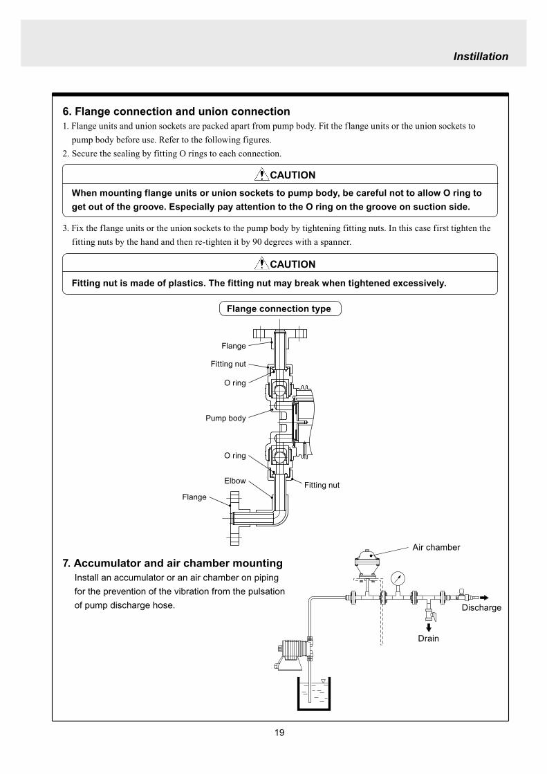
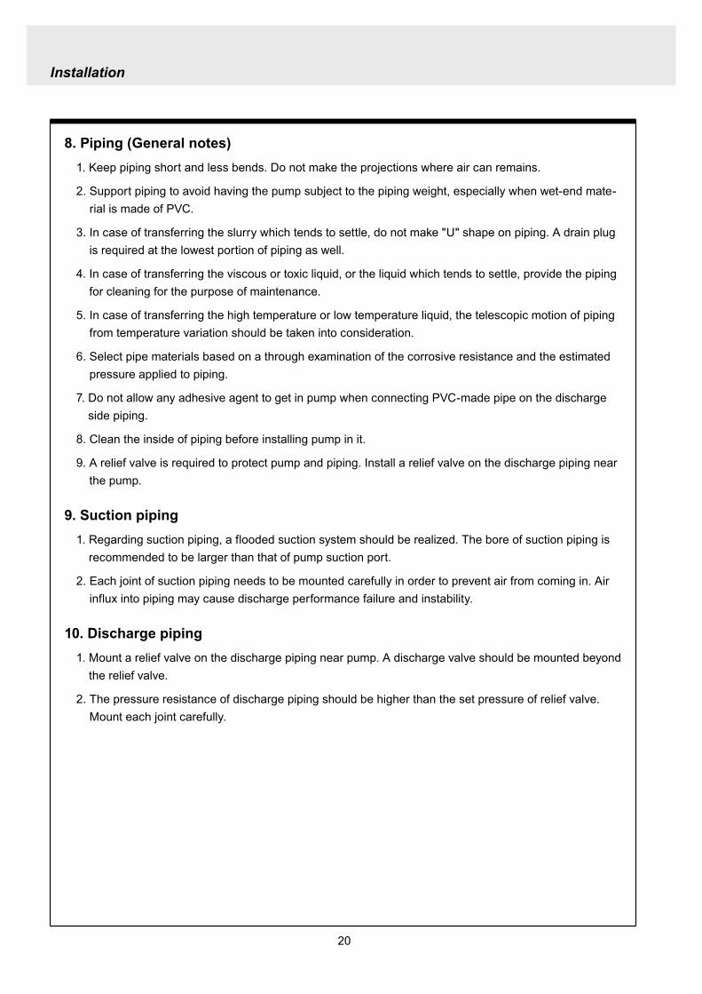

21
Installation
4 Electrical wiring
1 Power cord connection
Electrical works and the handling of power source must be done by qualified person
Do not operate pump with the wet hand
Make sure that power is not turned on while working on wirng
Do not dismantle electronic circuit
Electronic circuit may be broken Never apply other voltages than a rated voltage
WARNING
CAUT ION
High power equipment
CAUTION Avoid sharing a power source with a high
power equipment This can lead to the fail-ure of the electronic circuit of control unit due to extremely large surge voltage
The noise from an inverter can cause fail-ure
22
Installation
P
Surge absorption element
PNoise cut transformer
CAUTION
2 Wiring procedure
Electronic circuit of control unit may be failed by extremely large surge voltage Do not use the pump near to the high power equipment of 200V or more which may generate large surge voltage If the use of high power equipment is inevitable take either of the following measuresa Install a surge absorption element such
as varister with 2000A or more durability on the power point
b Install a noise cut transformer
CAUTION
Only qualified operatorsservice staff should be in charge of the related electrical arrange-ment and control of the power source Failure to observe this instruction may result in injury to person or damage to assets
Never connect wires while power is turned on otherwise an electrical shock or a short-circuit of controller may result Be sure to turn off power before wiring
Internal circuit is still electrified right after turning off power Take 1 minute or more to start wiring
Do not band a power cable either electrical wires or relay output wires
Earthing wire is equipped with a jumper pin Keep the jumper pin equipped in use
Do not combine the EXT or STOP signal line with a power cord or a power cable Do not com-bine power source line with the EXT or STOP signal line by a concentric cable (5 wires cable or so) Otherwise noise come about through EXT and STOP wires due to the induction effect from power cable and it may results in wrong operation or the failure of pump
Regarding frequent ON-OFF operation it is recommended to stop pump thorough STOP input terminal but not by connecting or disconnecting power source When connecting and discon-necting power cord can not be avoided it should be within 6 times an hour
23
Installation
Procedure to connect the signal cordUse DIN connector of five poles and four polesThe following connectors made by Binder in Germany are recommendedAsk IWAKI for the detail of Binder connector 5 poles 713 series 99-0436-10-05 for input signal 4 poles 715 series 99-0430-15-04 for level sensor
The following connector made by Hirschmann in Germany is recommendedAsk IWAKI for the detail of Hirschmann connector 4 poles GDS307 for output
The following procedures are based on the connector made by Binder and HirschmannIf a similar connector is used the wiring should be made according to the instruction manual of the manufacturer of connector
In case of Binder connector(1) Dismantle the connector and pass the wire through it Outer diameter of the cable should be oslash4-6
Using the different cable in diameter the connector can not be sealed properly
(2) Strip the cable ends and insert wire to the appropriate positions and connect them with screwsThe maximum allowable cross section of the wire is 075mm2
(3) After connecting the wire assemble the connector securely Slightly pull the cord to confirm that the cord connection is secured Perfect sealing can not be obtained unless the cord connection is loose
24
Installation
In case of Hirschmann connector(1) Dismantle the connector and pass the wire through it Insert a minus screw driver into the place shown by
ldquoLIFTrdquo and lift it up Outer diameter of the cable should be 35-6 mm Using the different cable in diam-eter the connector can not be sealed properly
(2) Strip the cable ends and insert wire to the appropriate positions and tighten them with screwsThe maximum allowable cross section of the wire is 075mm2
(3) After connecting wire assemble the connector securely Slightly pull the cord to confirm that the cord connection is secured Perfect sealing can not be obtained unless the cord connection is loose
Terminal position
NA Not Applicable
Connection of level sensorThe controller corresponds to two stage level sensor Connect the pre-alarm signal to Pre-STOP and the alarm signal to STOP When the pre-alarm signal comes in the orange lamp lights but the pump does not stop When a contact type is used connect wires to STOP and COM2 For open collector output level sensor Pay attention to the polarity Pre-Stop and STOP are plus (+) and COM2 is minus (-) (Max charged voltage 5V Current 18mA) For contact output level sensor Use the one designed for electronic circuit and the minimum applicable load of 1mA or less
Connection inside connector 1 STOP 2 Pre-STOP 3 Free 4 COM2
1
2
3
4 CLOSE
ON
PUMP
Level Sensor(STOP)
OPEN
Pulse
COM
+12VDC
NA
ANA(4-20)
Pre-STOP
STOP
COM
NA
OUT
25
Installation
Stop functionStop function is the function to stop the pump by the external signal Connect the wires to STOP and COM2 in the same way as the level sensor connection
CAUTION
Frequent stop and start of pump should be done by using STOP function (ON and OFF of STOP terminal) If you can not use STOP function and are forced to operate pump by turning OFF and ON of power source ON and OFF of power source should be limited to six times an hour
Pulse signal inputPulse signal input is used when the pump runs in the DIV or MULT of EXT modeDIV means dividing and MULT means multiply In case of open collector signal Pay attention to the polarity Pulse is plus (+) and COM1 is minus (-) (Max charged voltage 5V Current 18mA) In case of contact signal Use the one designed for electronic circuit and the minimum applicable load of 1mA or less
Connection inside connector 1 Free 2 Pulse 3 Free 4 12VDC 5 COM
3
2
4
15
Analog signal inputAnalog signal input is used when the pump runs in ANAR or ANAV of EXT modeANAR means analog rigid and ANAV means analog variable
Connection inside connector 1 ANA 2 Free 3 Free 4 Free 5 COM
3
2
4
15
26
Installation
Output signalOUT Photo MOS relay outputStandard is output synchronous with stroke Output is activated synchronous with each pump stroke
Connection inside connector 1 OUT 4 OUT
OUT 1
2
34
Surge voltage The electronic circuit of the control unit may be affected by excessively high surge voltage Do not operate the pump near the high-power elec-trical equipment of 200V or above that generates high surge voltage Under unavoidable circumstances take either of the following measures(1) Use a surge absorbing element (such as a
varistor with the surge resistance of 2000A or more) at the pump power supply connection
(2) Use a noise-cut transformer
Surge absorbing element
Noise-cut transformer
1 Preparation for pump operationBefore pump operation check that
bull Liquid tank is filled enough Supply liquid if it is less than the required levelbull There is no liquid leakage or congestion due to breakagebull Both suction and discharge side valves are openedbull Pump is connected to the predetermined power source correctlybull Electrical wiring is correct and there is no possibility of a short circuit or current leakage
2 BleedingBleeding is a process to eliminate the air inside the suction-side piping Be sure to carry out an air elimi-nation prior to initiating the pump operation after replacing the liquid inside a tank and after a long peri-od of storage Air gushes together with chemical liquid when carrying our bleeding For safety reasons first turn the end of a bleeding hose to a tank or a container
CAUTION
Some liquids may cause skin trouble or affect the quality of mechanical parts Wipe off chemi-cal liquid immediately when they splash on the hand or mechanical parts
27
Operation
1 Pump Operation
WA R N I N G Wear protective clothing
Wear protective clothing such as a protective mask safety gloves or so when handling chemical liquid
Do not operate pump with a discharge-side valve completely closed Operating the pump with the discharge-side valves fully closed may cause the liquid spillage or
the extremely high pressure inside the pump or the discharge-side pipingtubing This could lead to a piping burst Be sure not to operate pump with the discharge-sides valve closed
CAU T I O N A long time dry running (longer than 30 minutes) may cause the pump overheat and it could lead
to the deformation of the pump unit consists of a pump head and valve cases or so or may loosen the pump head fitting and result in liquid leakage
If the hex socket cap bolts on a pump head are loosened liquid leakage may resultBe sure to fasten all the 6 or 8 hex socket cap bolts tightly before starting the initial pump opera-tion And periodically check the looseness of the bolts on the pump head and retight the bolts as necessary
bull Tightening torque255NbullmTighten all the bolts diagonally applying equal tightness
If electric wiring gets wet due to accidental liquid spillage fire or electrical shock may occur Never get it wet When the electric wiring gets wet turn off power and wipe the liquid away
A frequent ON-OFF operation should be conducted by using STOP function(ON - OFF signals to STOP terminal) In case the STOP function is not available for the ON-OFF operation the ON - OFF operation by turning onoff power should be limited to six times an hour
4
28
3 Procedure for bleeding
Check valve should be removed
To tank or drain pan
100
75
50
25
0 25 50 75 100
(Fixed stroke length)
Stroke length adjustment
240spm
180spm
120spm
Flow
rate
Operation
[1] Extend the tube connected to the discharge-side fitting nut of pump to a chemical tank or a drain pan Then start pump operationbull Remove a check valve if it is installed on dis-
charge-side
[2] Operate the pump for about 10 minutes to eliminate air completely
[3] When the air in pump head is completely eliminated and liquid is replaced return the discharge-side tube to the regular tubing position
[4] Finally make sure there is no leakage in any section
4 Discharge capacity adjustmentDischarge capacity can be adjusted by both the stroke length adjustment and the stroke rate adjust-ment but basically adjust it via the stroke rate adjustment Stroke length adjustment is an auxiliary way to cover the range where the stroke rate adjustment can not reachPay attention to the following for correct procedure
Stroke rate adjustment(1) For some liquids which diffuses gas such as sodium hypochlorite and hydrazine solution adjust discharge capac-
ity by means of the stroke rate adjustment with the stroke length about 100 Gas lock may occur if the stroke length is set to short
(2) When the back pressure on discharge side is high adjust discharge capacity by the stroke rate adjustment with the stroke length about 100
(3) In case reaction is greatly influenced depending on the discharge capacity per pump shot in the application of neutralization or titration adjust discharge capacity by the stroke rate adjustment with the shortened stroke length and reduce the discharge capacity per shot
1 Discharge capacity adjustment procedureAppropriate stroke length and stroke rate are decided on the pump operating condition and liquid characteristics Following ways are recommended for proper calibration
(1) Set stroke length at 100 and roughly adjust discharge capacity by adjusting stroke rate
(2) Measure discharge capacity(3) If the measured capacity is below the wanted value
increase the stroke rate and measure again the dis-charge capacity
(4) Adjust stroke length for the fine adjustment of discharge capacity(5) Determine a discharge capacity at the last and confirm the wanted capacity is discharged
CAUTION
29
100
75
50
25
0 60 120 180 240spm
Fixed stroke length
Stroke rate adjustment
Flow
rate
Screw driverOPEN
LOCK
100
75
50
25
0 25 50 75 100
Fixed stroke rate
Flow
rate
Stroke length adjustment
Operation
2 Stroke rate adjustmentStroke rate is adjusted by the key operations of control unit Control the plunger stroke rate per minute from 1 to 240 spm via control unit
3 Stroke length adjustmentStroke length adjustment knob is locked with a screw Loosen the screw before adjustment and lock it afterwards
(1) Turn on pump and adjust the discharge capacity by turning the stroke length adjusting knob while pump is running
(2) The left graph shows the relation between stroke length and discharge capacity The maximum dis-charge capacity is shown on the name plate
bull The usage between 40 and 100 is practi-cal
Do not turn the stroke length adjusting knob when pump stops
CAUTIONBe sure to tighten the screw on the adjust-ment knob after an adjustment The knob may rotate unintentionally due to a loose fixation This may result in the fluctuation in a discharge rate
30
Mode ParameterDefault value
Setting range Step
Manual operation Stroke speed 240 1-240DIV setting Dividing ratio frasl 1 1-9999
MULT setting Multiply ratio times1 times1-9999ANA R setting 4-20 4-20 20-4 0-20 20-0
ANA V setting
P1 amperage 40 00-200P1 stroke speed 0 0-240P2 amperage 200 00-200P2 stroke speed 240 0-240
User setting
EXT operation ANA V DIV MULT ANA R ANA V
Anti-chatteringMECH MECH ELECST05 ST05 ST20 ST50FT01 FT02 FT04
Buffer memory MEM-N MEM-N MEM-Y
111-
011
011
2 Control unit operationEH-F type pump is controlled by means of setting or changing the setting values of the controller Control functions are various at each operation mode Read this section carefully before operation
Default parameter values
5 Full operationPut pump in use after bleeding and adjusting discharge capacityPump runs in manual operation or in accordance with the setting of control unit
6 Manual operationStarting pump After turning on power ON lamp (Green) appears and display shows WAIT mode For
the first time to turn on power MAN lamp appears and pump starts after pushing STARTSTOP key once
Stop pump Push STARTSTOP key to turn off MAN lamp and stop pump Pump starts and stops every time STARTSTOP key is pressed
7 EXT operationRefer to the next section of 2 Control unit operation
8 Shout down When pump will not in use for a long time (one month or more)
Run pump with clean water about 30 minutes in order to clean the wet-end parts and the inside of pip-ing before storage
When re-starting pump after a long time storage If pump dose not suck up liquid clean valve sets and remove the sticking foreign matters Carry out an air elimination and adjust discharge capacity when air stays inside pump head Refer to page 28 3 Procedure for bleeding
Operation
---
-
31
AN
A V
(Ana
log
var
iabl
e)
DIV
(Pul
se d
ivid
ing)
MU
LT(P
ulse
mul
tiply
)A
NA
R(A
nalo
g ri
gid)
SE
TS
ET
Use
r mod
e
EX
T m
ode
sele
ctio
n
EX
T
EX
TE
XT
EX
TE
XT
EX
T EX
T
EX
T
EX
T
EX
T
EX
T
EX
T
EX
T
EX
T
EX
T
EX
T
EX
T
EX
T
3 sec
onds
or m
ore
Wai
t mod
e
Set
ting
of fi
xatio
n pa
ttern
EX
T m
ode
Man
ual o
pera
tion
Set
ting
of s
troke
num
ber
AN
A R
(Ana
log
rigi
d)M
ULT
(Pul
se m
ultip
ly)
DIV
(Pul
se
div
idin
g)
AN
A V
(Ana
log
var
iabl
e)
anti-
chat
terin
gse
tting
dis
play
Setti
ng o
f div
idin
g ra
tioS
ettin
g of
cou
nt n
umbe
r
Curre
nt va
lue of
P1
Stro
ke nu
mbe
r of P
1
Curre
nt va
lue
of P
2
Stro
ke nu
mbe
r of P
2
EX
T O
pera
tion
Dis
play
EX
T se
tting
mod
e
Buf
fer m
emor
yse
tting
dis
play
Pow
er O
N
spm
MA
Nsp
m
spm
DIV
DIV
SE
TS
ET
MU
LT
MU
LTsp
mA
NA
V
spm
AN
AR
AN
AR
SE
Tm
AS
ET
mA
spm
AN
A
V
P1
mA
SE
T
spm
AN
A
V
P1
AN
AR
SE
Tm
A
AN
AR
SE
Tm
AS
ET
AN
A
V
P 2
SE
T
spm
AN
A
V
P 2
AN
AR
SE
Tm
A
AN
A
V
SE
TS
ET
SE
T
SE
T
SE
T
SE
T
SE
T
SE
T
SE
T
SE
T
SE
TS
ET
1 Overview Operating Scheme
Operation
1 means automatic transfer WAIT mode is selected when the power is switched on for the first time On and after the initial power activation pump restores the previous status right before the power is switched off
2 Regarding MANUAL mode pump starts operation by pushing STARTSTOP key at WAIT modePushing STARTSTOP key again the pump stops and returns to WAIT mode
3 Regarding EXT operation pushing EXT key at WAIT mode the pump moves to EXT mode and starts operationPushing STARTSTOP key stops the operation and returns the pump to WAIT mode
4 The change of each setting of EXT operation is accessible by pushing EXT key at EXT mode Pushing EXT key after the setting pump starts in EXT operation according to the changed setting
5 Pushing EXT key for 3 seconds at WAIT mode pump moves to USER mode At USER mode the EXT mode selection and the detailed setting such as the setting of buffer memory or so can be obtained
For details refer to each section of 2 Pump operation
2 Pump operation1 Operation of controller
Before turning on power confirm the specified power source on the nameplate
CAUTION
Connecting any other powers than the one shown on nameplate to pump is strictly prohibitedIt could lead to pump trouble or failure
Operation
32
1 Turning on powerDisplay shows WAIT mode when pump is turned on for the first time After the initial power activation the pump restores the previous mode right before the power was turned off last time If power is turned off at any setting modes WAIT mode appears at the next power activation
Stroke speed setting value is shown on display at WAIT mode ON lamp lights (Green)
EXT
EH-F ControllerSTARTSTOP
ON STOP
spm
33
2 Manual operation(1) Stroke speed can be adjusted by and
keys The figure changes quickly when either or key is depressed The picture below
shows the stroke speed is set to 160 spm
EXT
EH-F ControllerSTARTSTOP
ON STOP
spm
EXT
EH-F ControllerSTARTSTOP
ON STOP
MAN spm
EXT
EH-F ControllerSTARTSTOP
ON STOP
spm
(2) Push STARTSTOP key once to start the pump operation MAN indication appears and ON lamp blinks synchronously with each stroke
(3) MAN indication disappears and ON lamp stops blinking as STARTSTOP key is pushed again Pump enters WAIT mode
Operation
Operation
34
EXT
EH-F ControllerSTARTSTOP
ON STOP
ANA V
P1 SET mA
EXT
EH-F ControllerSTARTSTOP
ON STOP
P1 SET
ANA V spm
EXT
EH-F ControllerSTARTSTOP
ON STOP
spm
EXT
EH-F ControllerSTARTSTOP
ON STOP
ANA V spm
(4) Set the current value at P1 Figure increases or decreases as or key is pushed The pic-ture below shows 80 mA is set to point 1
EXT
EH-F ControllerSTARTSTOP
ON STOP
ANA V
P1 SET mA
(5) Pushing EXT key once spm appears on the display while mA disappears The picture below shows the number of strokes at P1
EXT
EH-F ControllerSTARTSTOP
ON STOP
P1 SET
ANA V spm
3 EXT operation (ANA V mode)(1) Push STARTSTOP key to move to WAIT mode
if pump is in another mode Go to next step if pump is in WAIT mode
(2) ANAV indication appears and pump enters an EXT mode as EXT key is pushed once Pump starts operation in accordance with current sig-nals and various settings ON lamp blinks at each pumping during operation Pump is con-trolled via the EXT mode which was select-ed at USER mode The initial setting of EXT mode is ANA V mode Select a preferable EXT mode in USER mode The picture below shows ANA V mode (The spm on the display changes according to input signals)
(3) Push EXT key once when pump is running in ANA V mode Display indicates the setting display of ANA V mode spm indication dis-appears and P1 SET and mA indications appear on the screen
(6) Set the number of strokes at P1 Figure increasesdecreases as key is pushed Picture below shows 10 spm is set for point 1
Operation
35
(7) Push EXT key to move to the setting display of the current value at P2 P1 and spm disap-pear and P2 and mA appears instead
EXT
EH-F ControllerSTARTSTOP
ON STOP
ANA V
P 2 SET mA
EXT
EH-F ControllerSTARTSTOP
ON STOP
ANA V
P 2 SET mA
EXT
EH-F ControllerSTARTSTOP
ON STOP
P 2 SET
ANA V spm
(11) Push EXT key to return to EXT mode Pump starts to run in ANA V mode on the setting of (4) through (10) ON lamp starts to blink at each pumping
EXT
EH-F ControllerSTARTSTOP
STOPON
ANA V spm
EXT
EH-F ControllerSTARTSTOP
ON STOP
P 2 SET
ANA V spm
EXT
EH-F ControllerSTARTSTOP
ON STOP
spm
(8) Set the current value of P2 by pushing and keys Picture below shows 180 mA is set to
point2
(9) Pushing EXT key once spm appears on the display while mA disappears The picture below shows the number of strokes at P2
(10) Set the number of strokes at P2 by pushing and keys Picture below shows 200
spm is set to point 2
(12) Pushing STARTSTOP key pump enters WAIT mode and pump stops ON lamp stops blink-ing and ANAV indication disappears
CAUTIONWhen the setting of the buffer memory is OFF keep the number of strokes in the dividing operation 240 spm or below The input signals to operate the pump over 240 spm can cause an unstable pump operationWhen the setting of the buffer memory is ON the pump operates for all the input pulse signalsPump keeps operating after all the signals are stopped in this case Be careful when setting of buffer memory
Operation
36
EXT
EH-F ControllerSTARTSTOP
ON STOP
DIV
SET
EXT
EH-F ControllerSTARTSTOP
ON STOP
DIV
SET
EXT
EH-F ControllerSTARTSTOP
STOPON
DIV spm
EXT
EH-F ControllerSTARTSTOP
ON STOP
spm
(2) Pushing EXT key DIV appears and pump starts operation in the ratio of input pulse sig-nals a pumping ON lamp blinks synchronous-ly at each pumping The initial setting of EXT selection is ANA V mode Change mode to DIV mode via USER mode Refer to P 40 for detail information
(3) Push EXT key while pump is operating in DIV mode Pump stop running and SET indication appears on the DIV setting display in stead of spm indication
(4) Enter a dividing ratioFigure increasesdecreases when key is pushed The picture below shows 10 is set
4 EXT operation (DIV mode)
(1) Push STARTSTOP key to move to WAIT mode if pump is in another mode Go to next step if pump is in WAIT mode
CAUTIONOn condition the setting of buffer memory is OFF do not input any pulse signals during the pumping motions for a input pulse signal in the multiply operation These input pulse signals are cancelledWhen the setting of buffer memory is ON pump operates for all the input pulse signals
Operation
37
EXT
EH-F ControllerSTARTSTOP
ON STOP
spm
EXT
EH-F ControllerSTARTSTOP
STOPON
DIV spm
EXT
EH-F ControllerSTARTSTOP
ON STOP
spm
EXT
EH-F ControllerSTARTSTOP
ON STOP
MULT
(5) Push EXT key to return to EXT operating mode Pump starts to run on the setting at item (4) ON lamp blinks synchronously at each pumping
(6) Pushing STARTSTOP key pump enters WAIT mode and pump stopsDIV indication disappears and ON lamp stops blinking
5 EXT operation (MULT mode)
(2) MULT indication appears and pump starts running in an EXT operation mode in the ratio of an input pulse signal pumpings as press-ing EXT key ON lamp blinks at each pump-ing Display shows the rest of the number of strokes In MULT mode the number of strokes is equal to the setting value in manual opera-tionThe initial setting of the EXT mode selection is ANA V mode which is the operation in pro-portion to current First select MULT mode via USER mode Refer to P 40 for detail informa-tion
(1) Push STARTSTOP key to move to WAIT mode if pump is in another mode Go to next step if pump is in WAIT mode
Operation
38
EXT
EH-F ControllerSTARTSTOP
ON STOP
spmEXT
EH-F ControllerSTARTSTOP
ON STOP
ANAR spm
EXT
EH-F ControllerSTARTSTOP
ON STOP
MULT
SET
EXT
EH-F ControllerSTARTSTOP
ON STOP
MULT
EXT
EH-F ControllerSTARTSTOP
ON STOP
spm
EXT
EH-F ControllerSTARTSTOP
ON STOP
MULT
SET
(5) Push EXT key to return to MULT mode(3) Pushing EXT key when pump is running in the multiply operation calls the setting display of MULT mode and SET indication appearsPump stops running and ON lamp stop blinking
(4) Enter the number of pumpings per input signalFigure increasesdecreases when key is pushed The picture below shows the pump-ing number is set to 1800 times per an input signal
6 EXT operation (ANA R mode)(1) Push STARTSTOP key to move to WAIT mode
if it is in another mode Go to next step if it is in WAIT mode
(6) Pushing STARTSTOP key recalls WAIT mode and pump stops spm indication appears in stead of MULT indication
(2) Pushing EXT key ANAR appears and pump starts running in the ratio of an input pulse sig-nal pumpings ON lamp blinks at each pump-ing The initial setting of the EXT mode selec-tion is ANA V mode which is the operation in proportion to current is selected First select ANA R mode in USER mode Refer to P 40 for more information
Operation
39
EXT
EH-F ControllerSTARTSTOP
ON STOP
ANAR
SET mA
EXT
EH-F ControllerSTARTSTOP
ON STOP
ANAR spm
EXT
EH-F ControllerSTARTSTOP
ON STOP
ANAR
SET mA
EXT
EH-F ControllerSTARTSTOP
ON STOP
spm
(4) Figure increasesdecreases when key is pushed The picture below is when it is set to 0-240 spm for 20-4 mA
(5) Push EXT key to return to EXT mode Pump starts to run on the setting at item (4) ON lamp blinks synchronously at each pumping
(6) When pushing STARTSTOP key pump enters WAIT mode and stops running ON lamp stops blinking and ANAR disappears
(3) Pushing EXT key when pump is running in the multiply operation calls the setting display of ANAR mode and SET and mA indications appear while spm disappears Pump stops running and ON lamp stops blinking
Operation
40
EXT
EH-F ControllerSTARTSTOP
ON STOP
ANA V
(5) Push EXT key to confirm the desired EXT mode Pump displays the EXT mode selection The picture below shows DIV appears to indi-cate DIV mode is selected
EXT
EH-F ControllerSTARTSTOP
ON STOP
DIV
EXT
EH-F ControllerSTARTSTOP
ON STOP
SET
EXT
EH-F ControllerSTARTSTOP
ON STOP
spm
EXT
EH-F ControllerSTARTSTOP
ON STOP
spm
EXT
EH-F ControllerSTARTSTOP
ON STOP
SET
7 USER settingThe setting of each function is changed in USER mode Have the pump entering WAIT mode in order to move to USER mode OUT (Output) is synchronous with spm and it can not be changed
7-1 EXT mode selection Any one of DIV (pulse dividing) MULT (pulse multiply) ANAR (analog rigid) or ANAV (analog vari-able) can be active in EXT mode The initial mode when shipped from factory is ANAV
(1) Push STARTSTOP key to move to WAIT mode if it is in another mode If it is in WAIT mode go to next step
(2) Press EXT key for more than 3 seconds to move to USER mode The picture below shows pump enters the EXT mode selection
(3) Pushing EXT key SET appears and display shows the mode currently set Picture below shows ANA V mode is selected
(4) Push or key to select a desired EXT mode The picture below shows DIV mode is selected
(6) Push STARTSTOP key to move to WAIT mode spm appears while DIV goes out
Operation
41
EXT
EH-F ControllerSTARTSTOP
ON STOP
spm
EXT
EH-F ControllerSTARTSTOP
ON STOP
ANA V
EXT
EH-F ControllerSTARTSTOP
ON STOP
SET
(3) Push key once
EXT
EH-F ControllerSTARTSTOP
ON STOP
(4) Push key again to move to the anti-chatter-ing setting display
EXT
EH-F ControllerSTARTSTOP
ON STOP
(5) Pushing EXT key display shows the mode cur-rently set and SET appears on it The picture below shows when MECH is selected
EXT
EH-F ControllerSTARTSTOP
ON STOP
SET
7-2 Setting of anti-chattering Anti-chattering function is settable against the incoming pulses during the DIV or MULT operation For the long chattering of mechanical contact such as relay set a large figure via MECH For the high speed (high frequency) chattering of the semi-conductor type contact such as transistor set a small figure via ELEC ST05 of MECH is initial setting
(6) Select MECH by or key for a mechani-cal contact And select ELEC for a semi-conductor contact The picture below shows ELEC is selected
(1) Push STARTSTOP key to move to WAIT mode if it is in another mode If it is in WAIT mode go to next step
(2) Press EXT key for more than 3 seconds to move to USER mode The picture below shows pump enters the EXT mode selection
Operation
42
EXT
EH-F ControllerSTARTSTOP
ON STOP
SET
(7) Push EXT key to display the current set state The picture below shows FT01 is selected
EXT
EH-F ControllerSTARTSTOP
ON STOP
SET EXT
EH-F ControllerSTARTSTOP
ON STOP
EXT
EH-F ControllerSTARTSTOP
ON STOP
spm
7-3 Setting of buffer memoryIn case pump operation can not catch up with the input pulse signals in DIV or MULT operation exces-sive pulse signals can be put in memory up to 65535 pulses However the excessive pulses can not be restored if once power is off or mode is changed
EXT
EH-F ControllerSTARTSTOP
ON STOP
spm
(2) Press EXT key for 3 seconds or more to move to USER mode The picture below shows the EXT mode selection display
EXT
EH-F ControllerSTARTSTOP
ON STOP
ANA V
(8) Set a large figure for the long chattering by or key and set a small figure for high speed (high frequency) chattering The picture below shows FT04 is selected
(9) Push EXT key to return to the anti-chattering setting display SET indication disappears
(10) Push STARTSTOP key to return to wait mode spm indication appears
(1) Push STARTSTOP key to move to WAIT mode if it is in another mode If it is in WAIT mode go to next
Operation
43
(3) Push key once
EXT
EH-F ControllerSTARTSTOP
ON STOP
(7) Push or key in order to set buffer memo-ry to ON or OFF Select MEM-Y to set it ON Select MEM-N for OFF setting The picture below shows when ON is set
EXT
EH-F ControllerSTARTSTOP
ON STOP
SET
(4) Push key once again
EXT
EH-F ControllerSTARTSTOP
ON STOP
(8) Push EXT key to return to the buffer memory setting display SET indication disappears
EXT
EH-F ControllerSTARTSTOP
ON STOP
(9) Push STARTSTOP key to return to WAIT mode spm indication appears
EXT
EH-F ControllerSTARTSTOP
ON STOP
spm
(5) Push key once again and the buffer memory setting display is shown
EXT
EH-F ControllerSTARTSTOP
ON STOP
(6) Push EXT key in order to display the current set state SET indication appears The picture below shows the buffer memory is set to OFF
EXT
EH-F ControllerSTARTSTOP
ON STOP
SET
Operation
44
8 Bleeding amp self-primingAt WAIT mode Manual operating mode and EXT operating mode pump operates at max speed tak-ing priority over any functions when both and keys are pushed at once Pump runs at max speed only when both keys are depressed Pump state returns to the previous mode once either or key is released Pressing and keys for 10 seconds keeps pump running at maximum speed In this state this fixation is released when pushing either or key once and pump returns to the previous mode
(1) When pump is running in ANAV mode
EXT
EH-F ControllerSTARTSTOP
ON STOP
ANA V spm
(2) Pump start to run at full speed when and keys are pressed at once Display shows
PRIME If either or key is released pump returns to the previous mode In this case pump returns to ANAV mode
EXT
EH-F ControllerSTARTSTOP
ON STOP
ANA V
(3) Pressing both and keys simultaneously for 10 seconds or more pump continues to run at full speed even if both keys are released In this case indication appearsPush either or key to release this state indication disappears and pump returns to the previous mode In this case pump returns to ANAV mode
EXT
EH-F ControllerSTARTSTOP
ON STOP
ANA V
Operation
45
10 Error display and release(1) In case Input signals fall to 4 mA or below while
4-20 or 20-4 is set to ANA R mode pump stops with DISCN blinking and Err on dis-play
(2) This error state can be released by push-ing STARTSTOP key and pumps enters wait mode In this case check the wiring and input signals
EXT
EH-F ControllerSTARTSTOP
ON STOP
ANAR
Err
spm
EXT
EH-F ControllerSTARTSTOP
ON STOP
spm
9 Key lockKey lock function is to prevent pump from being operated by some other person than user If STARTSTOP key is pressed for five seconds or more when pump is running or stops all key operations become ineffective with LOCK indication on display This function can be released by pressing STARTSTOP key for 5 seconds while LOCK lights
EXT
EH-F ControllerSTARTSTOP
ON STOP
MAN spm
LOCK
46
Do not conduct a maintenance work with the wet hands It can cause an electric shock
Before dismantling pump be sure to turn off power and check the pump is not electrified Do not
start a dismantlement work after stopping the pump by pushing the STARTSTOP key only Put up
the sign of ldquoMaintenance work is in progressrdquo in order to prevent a pump switch from turning on
unintentionally during the work Release the pressure of discharge piping and drain the liquid from
the wet end parts And then clean the inside of pump head
Wear protective clothing such as a protective mask globes goggles and chemical-proof wear
according to the handled chemical liquid during the work
WARNING
5 Maintenance
1 Trouble shootingTrouble Cause Troubleshooting
Pump dose not start Faulty wiring or disconnection in wiring Voltage is too low Failure in the electronic circuit of control unit
Pump dose not suck liquidDischarge amount is low
Air suction from suction piping Valve gasket is not installed Valve set assembling direction is wrong Pump is air-locked Pump stroke length is too short Suction-sidedischarge-side valve is clogged with
foreign matter Adhesion of valve onto valve seat
Discharge amount fluctuates
Liquid leaks
Key operation is ineffective Key is locked Release key lock
Pump doesnt run
Pump is in waiting mode Signals are not coming for EXT operation Pump is in EXT setting mode Pump is suspended with STOP
Move to operation mode Check wiring and correct the wrong part Move to EXT operating mode Release STOP function
Abnormal noise
Suction-sidedischarge-side valve is clogged with foreign matters
The sound absorption gasket is worn out Bearing is worn out Spring is damaged
Piping vibrates due to pulsation Bearing is worn out Spring is damaged
Install a accumulator or an air chamber The end of pump life span The end of pump life span
Suction-sidedischarge-side valve is clogged with foreign matters
Air is trapped in pump Overfeeding Diaphragm is damaged
Fittings are not tightly closed Pump head is not tightened Diaphragm is damaged O ring and valve gasket are not installed O ring is damaged
Correct wiring Inspect power source and provide measurement Replace the whole unit
Arrange piping again Install valve gasket Reassemble valve set Carry out air elimination Drive pump with 100 stroke length to prime liquid Then
reset stroke length Disassemble inspect and clean Disassemble inspect and clean
Tighten fittings Tighten pump head Replace diaphragm Install O ring and valve gasket Replace O ring
Disassemble inspect and clean
Carry out air elimination Install a check valve or a back pressure valve Replace diaphragm
Disassemble inspect and clean
The end of pump life span The end of pump life span The end of pump life span
Abnormal vibration
Input pulse can not be read Signals are not coming Anti-chattering setting is not proper
Check wiring and correct the wrong part Change the setting properly
Analog signal input can not be read
Wrong wiring Signals are over acceptable loaded resistance
Check wiring and correct wrong part The load resistance is 200Ω Use some devise which can
accept the load resistance
47
CAUTION Check periodically whether the bolts fixing pump head are tightened Tighten them as needed
The bolts fixing pump head may loosen in operation Tightening torque 255Nbullm
Maintenance
3
bull Tighten joint where leakage has occurredbull The excessive air bubbles in the discharged liquid mean air suc-
tion has been caused in system Examine the piping and tighten joint on where leaks
Is there liquid leakage or air suction at any joints on pump or piping
2 Maintenance and inspection
1 Daily inspectionPay attention to the following points during pump operation Stop pump immediately upon detecting abnormality and take measures according to the item Troubleshooting When wear parts come to the life time replace them by new ones
No
1
2
Check Point Description
Does pump lift liquid normally
bull Is liquid normally fedbull Is suction pressuredischarge pressure at normal levelbull Has liquid undergone quality change crystallization or solidifica-
tion
Abnormal noise or vibrationbull Abnormal noise or vibration may happen from the abnormal func-
tioning of pump
EXT setting can not be stored
After EXT setting STARTSTOP key is pushed for EXT by mistake
Push EXT key to operate pump in EXT mode
ldquoPRIME is kept indicated and other operations are inac-cessible
Self-priming function is active Push either or key to release the function
Analog signal input can not be read and DISCN indication appears
Wrong wiring or disconnection Check wiring and correct the wrong part Refer to page 45
for how to release an error indication
Trouble Cause Troubleshooting
48
Maintenance
2 Wear partsWear parts should be replaced in proper period for a long period of pump operation It is recommended that follow-ing parts are always ready for the replacementVC V6 PC P6 types
Parts Qty Life span
Pum
p he
ad
Valve set
EH-F35 EH-F45 EH-F55middot70
2sets
8000hours
Diaphragm 1
Refer to exploded view
Bac
k pr
essu
re v
alve
1
2
Che
ck v
alve
7 6 1
8 11 1
Diaphragm seat 1
O ring
Poppet check valve (With check gasket)
Check valve spring Spacer
Diaphragm
O ring
Note Durability of wear parts depend on the pumped liquid temperature and pressure Time to be replaced mentioned as above is the estimation obtained by continuous pump-ing of clean water at ambient temperature
8000hours
4000hours
49
3 Dismantlement and assembly
Getting wet with or coming in contact with chemicals and toxic liquid is harmful Wear protective clothing such as a protective mask globes goggles and chemical-proof wear during the work
Risk of electrical shock Be sure to turn off power and confirm that pump and devices are not electrified before the work
Release the pressure inside pump and a discharge hose by opening an air bleed valve on piping prior to loosening the piping connections or the dismantlement of pump Dismantlement with the pressure inside pump could lead to liquid spillage
Be careful not to touch residual liquid when dismantling pump Some liquids are harmful for skin or component parts Wipe off liquid when the hand or the component parts come in contact with liquid
WARNING
CAUT ION
Hose
Hose stopperFitting spacer
O ring
Fitting nut
Fitting
Pumphead
Remove the fittingwith a spanner
1 Valve set replacement Dismantlement1 Loosen a fitting nut and remove the hose con-
nected to pump head Pay attention to the liquid dripping
2 Loosen a fitting with a spanner to remove it Then detach the valve set from pump head
Maintenance
50
AssemblyAssembly procedure is in reverse order to disas-sembly Pay attention to the following when assembling valve set DispositionInsertion direction of valve set The wrong dispositioninsertion direction of valve
set component can lead to leakage and less dis-charge amount
O ring is fitted properly1 Discharge side valve set mounting
Put valve set in pump head and screw a fitting into a pump head by hand and then re-tighten it by 14 turns with a spanner
2 Suction side valve set mountingPut valve set in connection port and screw the fitting into pump head by hand and then re-tighten it by 14 turns with spanner
Note Pay attention to the mounting direction of the spacer fitted to EH-F45(VC V6 PC)Make sure the cut portion on the spacer of suction side should be downward the one of discharge side should be upward
Suction side
Discharge side
O ringValve gasket
Valve gasket
Valve gasket
Valve guideValveValve seatSpacer
O ring
Valve gasketValve guideValveValve seat
Spacer
1714
11
1312
11
1312
17
17
14
14
14
11
31
1312
31
17
14
11
1312
12
13
11
14
EH-F35
EH-F45
EH-F5570
Suct
ion
side
Dis
char
ge s
ide
For b
oth
suct
ion
and
disc
harg
e si
deFo
r bot
h su
ctio
nan
d di
scha
rge
side
VC V6 PC P6 Type
Maintenance
51
Pay attention not to lose diaphragm spacer and to apply the correct number of diaphragm spacers 0 to several pieces of diaphragm spacers are put between retainer and plunger to adjust the position of diaphragm The number of spacers mounted depends on the pump model There are the models which do not have spacers
Maintenance
2 Diaphragm replacement Dismantlement1 Set stroke length to 0 by adjusting stroke length
adjustment knob
2 Remove the pump head from the pump body by loos-ening hex socket cap bolts
3 Rotate a diaphragm anti-clockwise to remove it from a plunger pin The diaphragm is screwed into the plunger pin
AssemblyAssembly is done in reverse order to disassembly Follow the steps below1 Make sure the stroke length of pump is set to 0
prior to an assembly Operate pump to set the stroke length to 0 and
stop it Then turn off power
2 Fit a rear diaphragm seat a retainer and a diaphragm spacer into new diaphragm via the threaded pin and screw the diaphragm into the plunger pin
Fit the concave side of retainer into the convex side of diaphragm Pay attention the retainer dose not come off
3 Set the stroke length to 100 Operate pump to set the stroke length to 100
and stop it Then turn off power4 Install a pump head to a pump body by tightening
the hex sock cap bolts equally Tightening torque is 255Nbullm
52
4 Accessories1 Connection port bore bull Check valve bull Back pressure valve
Note1 Check valves and back pressure valves are options2 Regarding the connection of the discharge side of back pressure valve
NPT38 and NPT12 taper pipe thread is used for BV-N-CR
Pump type Connection port bore Check valve Back pressure valve
EH-F35VC empty38timesempty12 hose CA-3VCH-C6 ndash
empty38timesempty12 hose CA-3VEH-C6 ndashempty38timesempty12 hose CA-3VH-C6 ndashempty38timesempty12 hose CA-3VCH-C6 ndashempty38timesempty12 hose CA-3VEH-C6 ndashempty38timesempty12 hose CA-3VH-C6 ndash
V6
empty38timesempty12 hose ndash BV-3NV-C6Rempty38timesempty12 hose ndash BV-3NE-C6Rempty38timesempty12 hose ndash BV-3NPV-C6Rempty58timesempty34 hose ndash BV-3NV-C7Rempty58timesempty34 hose ndash BV-3NE-C7Rempty58timesempty34 hose ndash BV-3NPV-C7R
PC
EH-F45VCV6PC
EH-F55VCV6PC
EH-F70VCV6PC
Maintenance
53
Maintenance
5 Exploded view
1 General view The extent of dismantlement is within the following exploded view
Diaphragm spacer
Retainer
(Back up retainer)55 bull 70 types
Pump body
Valve set
Valve set
Pump head
Diaphragm
Rear diaphragm sheet
54
2 Pump head (Hose connection type)
EH-F45 type EH-F35 type
4
28
2930
3
1114
131211
131217
1897
1
17
111312111312
3
3029
28
4
1920
1920 21
17
111312
31
3
3029
28
4
131217
189
7
11
3114
14
4
282930
3
1
21
1515
EH-F55 type
4
28
2930
3
11
131217
18
9
7
10
1
1920 21
17
111312
3
30
29
28
4
EH-F70 type
4
28
2930
3
14
11131217
18
9
7
10
1
1920 21 17
111312
3
30
29
28
4
15 15
14
1414
14
14 14
Note1 The back up retainer of No10 is only for EH-F55 bull 70 typesNote2 The figure inside ( ) in the above table is for EH-F45 bull 55 bull 70 typesNote3 The number of the diaphragm spacers (No18) is not constant None or a few spacers is inserted at
each diaphragmNote4 The figure inside ( ) in the above table is for EH-F70Note5 EH-F35 bull 55 bull 70 (VC V6 PC ) types require 2 valve gaskets and EH-F45 (VC V6 PC) types
require 4 of themNote6 The spacer on No31 is for EH-F45 type only
No Name Qty1 Pump head 13 Fitting 24 Fitting nut 27 Diaphragm 19 Retainer 110 Back up retainer 1 Note111 Valve guide 4 (2) Note212 Valve seat13 Valve14 Valve gasket
No Name Qty
17 O ring 218 Diaphragm spacer 1 Note319 Hex socket head bolt 6 (8) Note420 Spring washer21 Plain washer28 Hose stopper 229 Fitting spacer 230 O ring 231 Spacer 2 Note6
15 Rear diaphragm seat 1
2 (4) Note54 (2) Note24 (2) Note2
6 (8) Note46 (8) Note4
Maintenance
55
Maintenance
3 Pump head (Flange connection type) EH-F55 type
30
3
11
131217
18
9
7
10
1
1920 21
17
11
1312
3
30
EH-F70 type
15
EH-F45 type EH-F35 type
30
3
11131211
131217
1897
1
17
11131211
1312
3
30
1920
1920 21
17
111312
31
3
131217
189
7
11
31
30
3
1
30
21
1515
30
3
11131217
18
9
7
10
1
1920 21 17
11
1312
3
30
15
32
33
33
32
4
32
433
43332
32
334
43332
32
33
32
334
44
1414
14 14 14
1414
14
14 14
NoNo Name Qty1 Pump head 13 Fitting 24 Fitting nut 27 Diaphragm 19 Retainer 110 Back up retainer 1 Note111 Valve guide 4(2)Note212 Valve seat 4(2)Note213 Valve 4(2)Note214 Valve gasket 2(4)Note5
Name Qty
17 O ring 218 Diaphragm spacer 1 Note319 Hex socket cap bolt 6(8)Note420 Spring washer 6(8)Note421 Plain washer 6(8)Note430 O ring 2
33 Union 2
31 Spacer 2 Note6
15 Rear diaphragm seat 1
32 Flange 2
Note1 The back up retainer of No10 is only for EH-F55 bull 70 typesNote2 The figure inside ( ) in the above table is for EH-F45 bull 55 bull 70 typesNote3 The number of the diaphragm spacers (No18) is not constant None or a few spacers is inserted at
each diaphragmNote4 The figure inside ( ) in the above table is for EH-F70Note5 EH-F35 bull 55 bull 70 (VC V6 ) types require 2 valve gaskets and EH-F45 (VC V6) types require 4 of
themNote6 The spacer on No31 is for EH-F45 type only
56
4 Pump head (Flange connection horizontal suction port type) EH-F55 type
30
3
11
131217
18
9
7
10
1
1920 21
17
111312
3
30
EH-F70 Type
15
EH-F45 Type EH-F35 type
30
3
11131211
131217
1897
1
17
111312111312
3
30
1920
1920 21
17
11131231
3
131217
189
7
11
31
30
3
1
30
21
1515
30
3
11131217
18
9
7
10
1
1920 21 17
111312
3
30
15
32
33
32
433
43334
32
32
334
43334
32
33
44
34
32
334
34
32
334
32
35 353535
1414
14 14 14
1414
14
14 14
No Name Qty1 Pump head 13 Fitting 24 Fitting nut 27 Diaphragm 19 Retainer 110 Back up retainer 1 Note111 Valve guide 4 (2) Note212 Valve seat13 Valve
15 Rear diaphragm sheet 114 Valve gasket
No Name Qty
18 Diaphragm spacer 1 Note319 Hex socket cap bolt20 Spring washer21 Plain washer
31 Spacer 2 Note6
35 Pipe 1
32 Flange 2
34 Elbow 133 Union 2
17 O ring 2
30 O ring 2
4 (2) Note24 (2) Note22 (4) Note5
6 (8) Note4
4 (2) Note24 (2) Note2
Maintenance
Note1 The back up retainer of No10 is only for EH-F55 bull 70 typesNote2 The figure inside ( ) in the above table is for EH-F45 bull 55 bull 70 typesNote3 The number of the diaphragm spacers (No18) is not constant None or a few spacers is inserted at
each diaphragmNote4 The figure inside ( ) in the above table is for EH-F70Note5 EH-F35 bull 55 bull 70 (VC V6) types require 2 valve gaskets and EH-F45 (VC V6) types require 4 of
themNote6 The spacer on No31 is for EH-F45 type only
57
5 Check valve CA-3 type
1 2 3 4 5 6 7 8 11 9 10
16
14
13
15
12
3
15
17
16
1110
98
7
1
54
2
6
14
13
6 Back pressure valve BV-3N-R type
No No Name Qty10 Stopper 111 Diaphragm 112 Lower case 113 Fitting spacer Hose port 114 Hose stopper Ferrule 115 O ring 216 Nut 217 Fitting 1
Name Qty1 Upper case 12 Hexhead bolt (with PW SW) 43 Hex nut 44 Adjusting bolt 15 Hexnut 16 Plain washer 1
8 Spring 19 Retainer plate 1
7 Spring seat 1
NoNo Name Qty1 Fitting nut 12 Hose stopper 13 Fitting spacer 14 O ring 15 Valve case 16 Gasket 1
Name Qty7 Poppet valve 18 Spring 19 O ring 110 Valve fitting 111 Spacer 1
Maintenance
58
Maintenance
1 Outer dimension (Hose connection type) EH-F35 type
TUBING(38rdquotimes12rdquo)
38rdquotimes12rdquo
EH-F45 type
38rdquotimes12rdquo
38rdquotimes12rdquo
59
EH-F55 type
58rdquotimes34rdquo
58rdquotimes34rdquo
EH-F70 type
Maintenance
38rdquotimes12rdquo
38rdquotimes12rdquo
60
Maintenance
2 Outer dimension (Flange connection type) EH-F35 type
EH-F45 type
61
EH-F55 type
EH-F70 type
Maintenance
62
Maintenance
3 Outer dimension (Flange connection horizontal suction port type) EH-F35 type
EH-F45 type
63
EH-F55 type
EH-F70Type
Maintenance
httpwwwiwakipumpsjp
Read this manual before use of product
IWAKIElectromagnetic Metering Pump
EH-F series (North America)
Instruction ManualT596 0706
GermanyItalyDenmarkSwedenFinlandNorwayFranceUKSwitzerlandAustriaHollandSpainBelgiumUSA
TEL (49)2154 9254 0TEL (39)02 990 3931TEL (45)48 24 2345TEL (46)8 511 72900TEL (358)9 2742714TEL (47)66 81 16 60TEL (33)1 69 63 33 70TEL (44)1743 231363TEL (41)26 674 9300TEL (43)2236 33469TEL (31)297 241121TEL (34)943 630030TEL (32)1367 0200TEL (1)508 429 1440
AustraliaSingaporeIndonesiaMalaysiaTaiwanThailandHong KongChinaChinaChinaChinaPhilippinesKoreaVietnam
TEL (61)2 9899 2411TEL (65)6316 2028TEL (62)21 690 6606TEL (60)3 7803 8807TEL (886)2 8227 6900TEL (66)2 322 2471TEL (852)2 607 1168TEL (86)750 380 9018TEL (86)20 8435 0603TEL (86)10 6442 7713TEL (86)21 6272 7502TEL (63)2 888 0245TEL (82)2 3474 0523TEL (84)613 933456
IWAKI EUROPE GmbH IWAKI Italia SRL IWAKI Nordic AS IWAKI Sverige AB IWAKI Suomi Oy IWAKI Norge AS IWAKI France SA IWAKI PUMPS (UK) LTD IWAKI (Schweiz) AG IWAKI (Austria) GmbH IWAKI Holland BV IWAKI Iberica Pumps SA IWAKI Belgium nv IWAKI America Incorporated
FAX 2154 1028FAX 02 990 42888FAX 48 24 2346FAX 8 511 72922FAX 9 2742715FAX 66 81 16 61FAX 1 64 49 92 73FAX 1743 366507FAX 26 674 9302FAX 2236 33469FAX 297 273902FAX 943 628799FAX 1367 2030FAX 508 429 1386
IWAKI Pumps Australia Pty Ltd IWAKI Singapore Pte Ltd IWAKI Singapore (Indonesia Branch) IWAKIm Sdn Bhd IWAKI Pumps Taiwan Co Ltd IWAKI (Thailand) CoLtd IWAKI Pumps Co Ltd IWAKI Pumps (Guandong) Co Ltd GFTZ IWAKI Engineering amp Trading (Guangzhou) IWAKI Pumps Co Ltd (Beijing) IWAKI Pumps (Shanghai) Co Ltd IWAKI Chemical Pumps Philippines Inc IWAKI Korea CoLtd IWAKI Pumps Vietnam Joint Venture CoLtd
FAX 2 9899 2421FAX 6316 3221FAX 21 690 6612FAX 3 7803 4800FAX 2 8227 6818FAX 2 322 2477FAX 2 607 1000FAX 750 380 9078FAX 20 8435 9181FAX 10 6442 7712FAX 21 6272 6929FAX 2 843 3096FAX 2 3474 0221FAX 613 933399
( )Country codes
IWAKI COLTD 6-6 Kanda-Sudacho 2-chome Chiyoda-ku Tokyo 101-8558 JapanTEL(81)3 3254 2935 FAX3 3252 8892(httpwwwiwakipumpsjp)
This is patent pending product
- 107
- 47
- 48
- 49
- 50
- 3
- 4
- 64
- 102
- 101
- 78
- 79
- 91
- 81
- 100
- 99
- 84
- 86
- 85
- 87
- 22
- 23
- 73
- 72
- 26
- 98
- 28
- 27
- 31
- 32
- 29
- 30
- 95
- 34
- 33
- 96
- 35
- 36
- 37
- 38
- 40
- 39
- 41
- 42
- 59
- 58
- 45
- 7
- 6
- 46
- 5
- 8
- 9
- 74
- 75
- 10
- 11
- 61
- 60
- 15
- 14
- 62
- 63
- 16
- 17
- 18
- 19
- 92
- 94
- 93
- 103
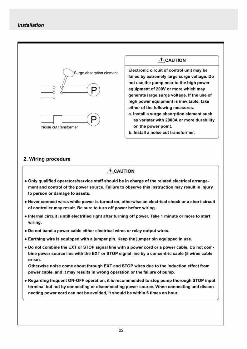

25
Installation
Stop functionStop function is the function to stop the pump by the external signal Connect the wires to STOP and COM2 in the same way as the level sensor connection
CAUTION
Frequent stop and start of pump should be done by using STOP function (ON and OFF of STOP terminal) If you can not use STOP function and are forced to operate pump by turning OFF and ON of power source ON and OFF of power source should be limited to six times an hour
Pulse signal inputPulse signal input is used when the pump runs in the DIV or MULT of EXT modeDIV means dividing and MULT means multiply In case of open collector signal Pay attention to the polarity Pulse is plus (+) and COM1 is minus (-) (Max charged voltage 5V Current 18mA) In case of contact signal Use the one designed for electronic circuit and the minimum applicable load of 1mA or less
Connection inside connector 1 Free 2 Pulse 3 Free 4 12VDC 5 COM
3
2
4
15
Analog signal inputAnalog signal input is used when the pump runs in ANAR or ANAV of EXT modeANAR means analog rigid and ANAV means analog variable
Connection inside connector 1 ANA 2 Free 3 Free 4 Free 5 COM
3
2
4
15
26
Installation
Output signalOUT Photo MOS relay outputStandard is output synchronous with stroke Output is activated synchronous with each pump stroke
Connection inside connector 1 OUT 4 OUT
OUT 1
2
34
Surge voltage The electronic circuit of the control unit may be affected by excessively high surge voltage Do not operate the pump near the high-power elec-trical equipment of 200V or above that generates high surge voltage Under unavoidable circumstances take either of the following measures(1) Use a surge absorbing element (such as a
varistor with the surge resistance of 2000A or more) at the pump power supply connection
(2) Use a noise-cut transformer
Surge absorbing element
Noise-cut transformer
1 Preparation for pump operationBefore pump operation check that
bull Liquid tank is filled enough Supply liquid if it is less than the required levelbull There is no liquid leakage or congestion due to breakagebull Both suction and discharge side valves are openedbull Pump is connected to the predetermined power source correctlybull Electrical wiring is correct and there is no possibility of a short circuit or current leakage
2 BleedingBleeding is a process to eliminate the air inside the suction-side piping Be sure to carry out an air elimi-nation prior to initiating the pump operation after replacing the liquid inside a tank and after a long peri-od of storage Air gushes together with chemical liquid when carrying our bleeding For safety reasons first turn the end of a bleeding hose to a tank or a container
CAUTION
Some liquids may cause skin trouble or affect the quality of mechanical parts Wipe off chemi-cal liquid immediately when they splash on the hand or mechanical parts
27
Operation
1 Pump Operation
WA R N I N G Wear protective clothing
Wear protective clothing such as a protective mask safety gloves or so when handling chemical liquid
Do not operate pump with a discharge-side valve completely closed Operating the pump with the discharge-side valves fully closed may cause the liquid spillage or
the extremely high pressure inside the pump or the discharge-side pipingtubing This could lead to a piping burst Be sure not to operate pump with the discharge-sides valve closed
CAU T I O N A long time dry running (longer than 30 minutes) may cause the pump overheat and it could lead
to the deformation of the pump unit consists of a pump head and valve cases or so or may loosen the pump head fitting and result in liquid leakage
If the hex socket cap bolts on a pump head are loosened liquid leakage may resultBe sure to fasten all the 6 or 8 hex socket cap bolts tightly before starting the initial pump opera-tion And periodically check the looseness of the bolts on the pump head and retight the bolts as necessary
bull Tightening torque255NbullmTighten all the bolts diagonally applying equal tightness
If electric wiring gets wet due to accidental liquid spillage fire or electrical shock may occur Never get it wet When the electric wiring gets wet turn off power and wipe the liquid away
A frequent ON-OFF operation should be conducted by using STOP function(ON - OFF signals to STOP terminal) In case the STOP function is not available for the ON-OFF operation the ON - OFF operation by turning onoff power should be limited to six times an hour
4
28
3 Procedure for bleeding
Check valve should be removed
To tank or drain pan
100
75
50
25
0 25 50 75 100
(Fixed stroke length)
Stroke length adjustment
240spm
180spm
120spm
Flow
rate
Operation
[1] Extend the tube connected to the discharge-side fitting nut of pump to a chemical tank or a drain pan Then start pump operationbull Remove a check valve if it is installed on dis-
charge-side
[2] Operate the pump for about 10 minutes to eliminate air completely
[3] When the air in pump head is completely eliminated and liquid is replaced return the discharge-side tube to the regular tubing position
[4] Finally make sure there is no leakage in any section
4 Discharge capacity adjustmentDischarge capacity can be adjusted by both the stroke length adjustment and the stroke rate adjust-ment but basically adjust it via the stroke rate adjustment Stroke length adjustment is an auxiliary way to cover the range where the stroke rate adjustment can not reachPay attention to the following for correct procedure
Stroke rate adjustment(1) For some liquids which diffuses gas such as sodium hypochlorite and hydrazine solution adjust discharge capac-
ity by means of the stroke rate adjustment with the stroke length about 100 Gas lock may occur if the stroke length is set to short
(2) When the back pressure on discharge side is high adjust discharge capacity by the stroke rate adjustment with the stroke length about 100
(3) In case reaction is greatly influenced depending on the discharge capacity per pump shot in the application of neutralization or titration adjust discharge capacity by the stroke rate adjustment with the shortened stroke length and reduce the discharge capacity per shot
1 Discharge capacity adjustment procedureAppropriate stroke length and stroke rate are decided on the pump operating condition and liquid characteristics Following ways are recommended for proper calibration
(1) Set stroke length at 100 and roughly adjust discharge capacity by adjusting stroke rate
(2) Measure discharge capacity(3) If the measured capacity is below the wanted value
increase the stroke rate and measure again the dis-charge capacity
(4) Adjust stroke length for the fine adjustment of discharge capacity(5) Determine a discharge capacity at the last and confirm the wanted capacity is discharged
CAUTION
29
100
75
50
25
0 60 120 180 240spm
Fixed stroke length
Stroke rate adjustment
Flow
rate
Screw driverOPEN
LOCK
100
75
50
25
0 25 50 75 100
Fixed stroke rate
Flow
rate
Stroke length adjustment
Operation
2 Stroke rate adjustmentStroke rate is adjusted by the key operations of control unit Control the plunger stroke rate per minute from 1 to 240 spm via control unit
3 Stroke length adjustmentStroke length adjustment knob is locked with a screw Loosen the screw before adjustment and lock it afterwards
(1) Turn on pump and adjust the discharge capacity by turning the stroke length adjusting knob while pump is running
(2) The left graph shows the relation between stroke length and discharge capacity The maximum dis-charge capacity is shown on the name plate
bull The usage between 40 and 100 is practi-cal
Do not turn the stroke length adjusting knob when pump stops
CAUTIONBe sure to tighten the screw on the adjust-ment knob after an adjustment The knob may rotate unintentionally due to a loose fixation This may result in the fluctuation in a discharge rate
30
Mode ParameterDefault value
Setting range Step
Manual operation Stroke speed 240 1-240DIV setting Dividing ratio frasl 1 1-9999
MULT setting Multiply ratio times1 times1-9999ANA R setting 4-20 4-20 20-4 0-20 20-0
ANA V setting
P1 amperage 40 00-200P1 stroke speed 0 0-240P2 amperage 200 00-200P2 stroke speed 240 0-240
User setting
EXT operation ANA V DIV MULT ANA R ANA V
Anti-chatteringMECH MECH ELECST05 ST05 ST20 ST50FT01 FT02 FT04
Buffer memory MEM-N MEM-N MEM-Y
111-
011
011
2 Control unit operationEH-F type pump is controlled by means of setting or changing the setting values of the controller Control functions are various at each operation mode Read this section carefully before operation
Default parameter values
5 Full operationPut pump in use after bleeding and adjusting discharge capacityPump runs in manual operation or in accordance with the setting of control unit
6 Manual operationStarting pump After turning on power ON lamp (Green) appears and display shows WAIT mode For
the first time to turn on power MAN lamp appears and pump starts after pushing STARTSTOP key once
Stop pump Push STARTSTOP key to turn off MAN lamp and stop pump Pump starts and stops every time STARTSTOP key is pressed
7 EXT operationRefer to the next section of 2 Control unit operation
8 Shout down When pump will not in use for a long time (one month or more)
Run pump with clean water about 30 minutes in order to clean the wet-end parts and the inside of pip-ing before storage
When re-starting pump after a long time storage If pump dose not suck up liquid clean valve sets and remove the sticking foreign matters Carry out an air elimination and adjust discharge capacity when air stays inside pump head Refer to page 28 3 Procedure for bleeding
Operation
---
-
31
AN
A V
(Ana
log
var
iabl
e)
DIV
(Pul
se d
ivid
ing)
MU
LT(P
ulse
mul
tiply
)A
NA
R(A
nalo
g ri
gid)
SE
TS
ET
Use
r mod
e
EX
T m
ode
sele
ctio
n
EX
T
EX
TE
XT
EX
TE
XT
EX
T EX
T
EX
T
EX
T
EX
T
EX
T
EX
T
EX
T
EX
T
EX
T
EX
T
EX
T
EX
T
3 sec
onds
or m
ore
Wai
t mod
e
Set
ting
of fi
xatio
n pa
ttern
EX
T m
ode
Man
ual o
pera
tion
Set
ting
of s
troke
num
ber
AN
A R
(Ana
log
rigi
d)M
ULT
(Pul
se m
ultip
ly)
DIV
(Pul
se
div
idin
g)
AN
A V
(Ana
log
var
iabl
e)
anti-
chat
terin
gse
tting
dis
play
Setti
ng o
f div
idin
g ra
tioS
ettin
g of
cou
nt n
umbe
r
Curre
nt va
lue of
P1
Stro
ke nu
mbe
r of P
1
Curre
nt va
lue
of P
2
Stro
ke nu
mbe
r of P
2
EX
T O
pera
tion
Dis
play
EX
T se
tting
mod
e
Buf
fer m
emor
yse
tting
dis
play
Pow
er O
N
spm
MA
Nsp
m
spm
DIV
DIV
SE
TS
ET
MU
LT
MU
LTsp
mA
NA
V
spm
AN
AR
AN
AR
SE
Tm
AS
ET
mA
spm
AN
A
V
P1
mA
SE
T
spm
AN
A
V
P1
AN
AR
SE
Tm
A
AN
AR
SE
Tm
AS
ET
AN
A
V
P 2
SE
T
spm
AN
A
V
P 2
AN
AR
SE
Tm
A
AN
A
V
SE
TS
ET
SE
T
SE
T
SE
T
SE
T
SE
T
SE
T
SE
T
SE
T
SE
TS
ET
1 Overview Operating Scheme
Operation
1 means automatic transfer WAIT mode is selected when the power is switched on for the first time On and after the initial power activation pump restores the previous status right before the power is switched off
2 Regarding MANUAL mode pump starts operation by pushing STARTSTOP key at WAIT modePushing STARTSTOP key again the pump stops and returns to WAIT mode
3 Regarding EXT operation pushing EXT key at WAIT mode the pump moves to EXT mode and starts operationPushing STARTSTOP key stops the operation and returns the pump to WAIT mode
4 The change of each setting of EXT operation is accessible by pushing EXT key at EXT mode Pushing EXT key after the setting pump starts in EXT operation according to the changed setting
5 Pushing EXT key for 3 seconds at WAIT mode pump moves to USER mode At USER mode the EXT mode selection and the detailed setting such as the setting of buffer memory or so can be obtained
For details refer to each section of 2 Pump operation
2 Pump operation1 Operation of controller
Before turning on power confirm the specified power source on the nameplate
CAUTION
Connecting any other powers than the one shown on nameplate to pump is strictly prohibitedIt could lead to pump trouble or failure
Operation
32
1 Turning on powerDisplay shows WAIT mode when pump is turned on for the first time After the initial power activation the pump restores the previous mode right before the power was turned off last time If power is turned off at any setting modes WAIT mode appears at the next power activation
Stroke speed setting value is shown on display at WAIT mode ON lamp lights (Green)
EXT
EH-F ControllerSTARTSTOP
ON STOP
spm
33
2 Manual operation(1) Stroke speed can be adjusted by and
keys The figure changes quickly when either or key is depressed The picture below
shows the stroke speed is set to 160 spm
EXT
EH-F ControllerSTARTSTOP
ON STOP
spm
EXT
EH-F ControllerSTARTSTOP
ON STOP
MAN spm
EXT
EH-F ControllerSTARTSTOP
ON STOP
spm
(2) Push STARTSTOP key once to start the pump operation MAN indication appears and ON lamp blinks synchronously with each stroke
(3) MAN indication disappears and ON lamp stops blinking as STARTSTOP key is pushed again Pump enters WAIT mode
Operation
Operation
34
EXT
EH-F ControllerSTARTSTOP
ON STOP
ANA V
P1 SET mA
EXT
EH-F ControllerSTARTSTOP
ON STOP
P1 SET
ANA V spm
EXT
EH-F ControllerSTARTSTOP
ON STOP
spm
EXT
EH-F ControllerSTARTSTOP
ON STOP
ANA V spm
(4) Set the current value at P1 Figure increases or decreases as or key is pushed The pic-ture below shows 80 mA is set to point 1
EXT
EH-F ControllerSTARTSTOP
ON STOP
ANA V
P1 SET mA
(5) Pushing EXT key once spm appears on the display while mA disappears The picture below shows the number of strokes at P1
EXT
EH-F ControllerSTARTSTOP
ON STOP
P1 SET
ANA V spm
3 EXT operation (ANA V mode)(1) Push STARTSTOP key to move to WAIT mode
if pump is in another mode Go to next step if pump is in WAIT mode
(2) ANAV indication appears and pump enters an EXT mode as EXT key is pushed once Pump starts operation in accordance with current sig-nals and various settings ON lamp blinks at each pumping during operation Pump is con-trolled via the EXT mode which was select-ed at USER mode The initial setting of EXT mode is ANA V mode Select a preferable EXT mode in USER mode The picture below shows ANA V mode (The spm on the display changes according to input signals)
(3) Push EXT key once when pump is running in ANA V mode Display indicates the setting display of ANA V mode spm indication dis-appears and P1 SET and mA indications appear on the screen
(6) Set the number of strokes at P1 Figure increasesdecreases as key is pushed Picture below shows 10 spm is set for point 1
Operation
35
(7) Push EXT key to move to the setting display of the current value at P2 P1 and spm disap-pear and P2 and mA appears instead
EXT
EH-F ControllerSTARTSTOP
ON STOP
ANA V
P 2 SET mA
EXT
EH-F ControllerSTARTSTOP
ON STOP
ANA V
P 2 SET mA
EXT
EH-F ControllerSTARTSTOP
ON STOP
P 2 SET
ANA V spm
(11) Push EXT key to return to EXT mode Pump starts to run in ANA V mode on the setting of (4) through (10) ON lamp starts to blink at each pumping
EXT
EH-F ControllerSTARTSTOP
STOPON
ANA V spm
EXT
EH-F ControllerSTARTSTOP
ON STOP
P 2 SET
ANA V spm
EXT
EH-F ControllerSTARTSTOP
ON STOP
spm
(8) Set the current value of P2 by pushing and keys Picture below shows 180 mA is set to
point2
(9) Pushing EXT key once spm appears on the display while mA disappears The picture below shows the number of strokes at P2
(10) Set the number of strokes at P2 by pushing and keys Picture below shows 200
spm is set to point 2
(12) Pushing STARTSTOP key pump enters WAIT mode and pump stops ON lamp stops blink-ing and ANAV indication disappears
CAUTIONWhen the setting of the buffer memory is OFF keep the number of strokes in the dividing operation 240 spm or below The input signals to operate the pump over 240 spm can cause an unstable pump operationWhen the setting of the buffer memory is ON the pump operates for all the input pulse signalsPump keeps operating after all the signals are stopped in this case Be careful when setting of buffer memory
Operation
36
EXT
EH-F ControllerSTARTSTOP
ON STOP
DIV
SET
EXT
EH-F ControllerSTARTSTOP
ON STOP
DIV
SET
EXT
EH-F ControllerSTARTSTOP
STOPON
DIV spm
EXT
EH-F ControllerSTARTSTOP
ON STOP
spm
(2) Pushing EXT key DIV appears and pump starts operation in the ratio of input pulse sig-nals a pumping ON lamp blinks synchronous-ly at each pumping The initial setting of EXT selection is ANA V mode Change mode to DIV mode via USER mode Refer to P 40 for detail information
(3) Push EXT key while pump is operating in DIV mode Pump stop running and SET indication appears on the DIV setting display in stead of spm indication
(4) Enter a dividing ratioFigure increasesdecreases when key is pushed The picture below shows 10 is set
4 EXT operation (DIV mode)
(1) Push STARTSTOP key to move to WAIT mode if pump is in another mode Go to next step if pump is in WAIT mode
CAUTIONOn condition the setting of buffer memory is OFF do not input any pulse signals during the pumping motions for a input pulse signal in the multiply operation These input pulse signals are cancelledWhen the setting of buffer memory is ON pump operates for all the input pulse signals
Operation
37
EXT
EH-F ControllerSTARTSTOP
ON STOP
spm
EXT
EH-F ControllerSTARTSTOP
STOPON
DIV spm
EXT
EH-F ControllerSTARTSTOP
ON STOP
spm
EXT
EH-F ControllerSTARTSTOP
ON STOP
MULT
(5) Push EXT key to return to EXT operating mode Pump starts to run on the setting at item (4) ON lamp blinks synchronously at each pumping
(6) Pushing STARTSTOP key pump enters WAIT mode and pump stopsDIV indication disappears and ON lamp stops blinking
5 EXT operation (MULT mode)
(2) MULT indication appears and pump starts running in an EXT operation mode in the ratio of an input pulse signal pumpings as press-ing EXT key ON lamp blinks at each pump-ing Display shows the rest of the number of strokes In MULT mode the number of strokes is equal to the setting value in manual opera-tionThe initial setting of the EXT mode selection is ANA V mode which is the operation in pro-portion to current First select MULT mode via USER mode Refer to P 40 for detail informa-tion
(1) Push STARTSTOP key to move to WAIT mode if pump is in another mode Go to next step if pump is in WAIT mode
Operation
38
EXT
EH-F ControllerSTARTSTOP
ON STOP
spmEXT
EH-F ControllerSTARTSTOP
ON STOP
ANAR spm
EXT
EH-F ControllerSTARTSTOP
ON STOP
MULT
SET
EXT
EH-F ControllerSTARTSTOP
ON STOP
MULT
EXT
EH-F ControllerSTARTSTOP
ON STOP
spm
EXT
EH-F ControllerSTARTSTOP
ON STOP
MULT
SET
(5) Push EXT key to return to MULT mode(3) Pushing EXT key when pump is running in the multiply operation calls the setting display of MULT mode and SET indication appearsPump stops running and ON lamp stop blinking
(4) Enter the number of pumpings per input signalFigure increasesdecreases when key is pushed The picture below shows the pump-ing number is set to 1800 times per an input signal
6 EXT operation (ANA R mode)(1) Push STARTSTOP key to move to WAIT mode
if it is in another mode Go to next step if it is in WAIT mode
(6) Pushing STARTSTOP key recalls WAIT mode and pump stops spm indication appears in stead of MULT indication
(2) Pushing EXT key ANAR appears and pump starts running in the ratio of an input pulse sig-nal pumpings ON lamp blinks at each pump-ing The initial setting of the EXT mode selec-tion is ANA V mode which is the operation in proportion to current is selected First select ANA R mode in USER mode Refer to P 40 for more information
Operation
39
EXT
EH-F ControllerSTARTSTOP
ON STOP
ANAR
SET mA
EXT
EH-F ControllerSTARTSTOP
ON STOP
ANAR spm
EXT
EH-F ControllerSTARTSTOP
ON STOP
ANAR
SET mA
EXT
EH-F ControllerSTARTSTOP
ON STOP
spm
(4) Figure increasesdecreases when key is pushed The picture below is when it is set to 0-240 spm for 20-4 mA
(5) Push EXT key to return to EXT mode Pump starts to run on the setting at item (4) ON lamp blinks synchronously at each pumping
(6) When pushing STARTSTOP key pump enters WAIT mode and stops running ON lamp stops blinking and ANAR disappears
(3) Pushing EXT key when pump is running in the multiply operation calls the setting display of ANAR mode and SET and mA indications appear while spm disappears Pump stops running and ON lamp stops blinking
Operation
40
EXT
EH-F ControllerSTARTSTOP
ON STOP
ANA V
(5) Push EXT key to confirm the desired EXT mode Pump displays the EXT mode selection The picture below shows DIV appears to indi-cate DIV mode is selected
EXT
EH-F ControllerSTARTSTOP
ON STOP
DIV
EXT
EH-F ControllerSTARTSTOP
ON STOP
SET
EXT
EH-F ControllerSTARTSTOP
ON STOP
spm
EXT
EH-F ControllerSTARTSTOP
ON STOP
spm
EXT
EH-F ControllerSTARTSTOP
ON STOP
SET
7 USER settingThe setting of each function is changed in USER mode Have the pump entering WAIT mode in order to move to USER mode OUT (Output) is synchronous with spm and it can not be changed
7-1 EXT mode selection Any one of DIV (pulse dividing) MULT (pulse multiply) ANAR (analog rigid) or ANAV (analog vari-able) can be active in EXT mode The initial mode when shipped from factory is ANAV
(1) Push STARTSTOP key to move to WAIT mode if it is in another mode If it is in WAIT mode go to next step
(2) Press EXT key for more than 3 seconds to move to USER mode The picture below shows pump enters the EXT mode selection
(3) Pushing EXT key SET appears and display shows the mode currently set Picture below shows ANA V mode is selected
(4) Push or key to select a desired EXT mode The picture below shows DIV mode is selected
(6) Push STARTSTOP key to move to WAIT mode spm appears while DIV goes out
Operation
41
EXT
EH-F ControllerSTARTSTOP
ON STOP
spm
EXT
EH-F ControllerSTARTSTOP
ON STOP
ANA V
EXT
EH-F ControllerSTARTSTOP
ON STOP
SET
(3) Push key once
EXT
EH-F ControllerSTARTSTOP
ON STOP
(4) Push key again to move to the anti-chatter-ing setting display
EXT
EH-F ControllerSTARTSTOP
ON STOP
(5) Pushing EXT key display shows the mode cur-rently set and SET appears on it The picture below shows when MECH is selected
EXT
EH-F ControllerSTARTSTOP
ON STOP
SET
7-2 Setting of anti-chattering Anti-chattering function is settable against the incoming pulses during the DIV or MULT operation For the long chattering of mechanical contact such as relay set a large figure via MECH For the high speed (high frequency) chattering of the semi-conductor type contact such as transistor set a small figure via ELEC ST05 of MECH is initial setting
(6) Select MECH by or key for a mechani-cal contact And select ELEC for a semi-conductor contact The picture below shows ELEC is selected
(1) Push STARTSTOP key to move to WAIT mode if it is in another mode If it is in WAIT mode go to next step
(2) Press EXT key for more than 3 seconds to move to USER mode The picture below shows pump enters the EXT mode selection
Operation
42
EXT
EH-F ControllerSTARTSTOP
ON STOP
SET
(7) Push EXT key to display the current set state The picture below shows FT01 is selected
EXT
EH-F ControllerSTARTSTOP
ON STOP
SET EXT
EH-F ControllerSTARTSTOP
ON STOP
EXT
EH-F ControllerSTARTSTOP
ON STOP
spm
7-3 Setting of buffer memoryIn case pump operation can not catch up with the input pulse signals in DIV or MULT operation exces-sive pulse signals can be put in memory up to 65535 pulses However the excessive pulses can not be restored if once power is off or mode is changed
EXT
EH-F ControllerSTARTSTOP
ON STOP
spm
(2) Press EXT key for 3 seconds or more to move to USER mode The picture below shows the EXT mode selection display
EXT
EH-F ControllerSTARTSTOP
ON STOP
ANA V
(8) Set a large figure for the long chattering by or key and set a small figure for high speed (high frequency) chattering The picture below shows FT04 is selected
(9) Push EXT key to return to the anti-chattering setting display SET indication disappears
(10) Push STARTSTOP key to return to wait mode spm indication appears
(1) Push STARTSTOP key to move to WAIT mode if it is in another mode If it is in WAIT mode go to next
Operation
43
(3) Push key once
EXT
EH-F ControllerSTARTSTOP
ON STOP
(7) Push or key in order to set buffer memo-ry to ON or OFF Select MEM-Y to set it ON Select MEM-N for OFF setting The picture below shows when ON is set
EXT
EH-F ControllerSTARTSTOP
ON STOP
SET
(4) Push key once again
EXT
EH-F ControllerSTARTSTOP
ON STOP
(8) Push EXT key to return to the buffer memory setting display SET indication disappears
EXT
EH-F ControllerSTARTSTOP
ON STOP
(9) Push STARTSTOP key to return to WAIT mode spm indication appears
EXT
EH-F ControllerSTARTSTOP
ON STOP
spm
(5) Push key once again and the buffer memory setting display is shown
EXT
EH-F ControllerSTARTSTOP
ON STOP
(6) Push EXT key in order to display the current set state SET indication appears The picture below shows the buffer memory is set to OFF
EXT
EH-F ControllerSTARTSTOP
ON STOP
SET
Operation
44
8 Bleeding amp self-primingAt WAIT mode Manual operating mode and EXT operating mode pump operates at max speed tak-ing priority over any functions when both and keys are pushed at once Pump runs at max speed only when both keys are depressed Pump state returns to the previous mode once either or key is released Pressing and keys for 10 seconds keeps pump running at maximum speed In this state this fixation is released when pushing either or key once and pump returns to the previous mode
(1) When pump is running in ANAV mode
EXT
EH-F ControllerSTARTSTOP
ON STOP
ANA V spm
(2) Pump start to run at full speed when and keys are pressed at once Display shows
PRIME If either or key is released pump returns to the previous mode In this case pump returns to ANAV mode
EXT
EH-F ControllerSTARTSTOP
ON STOP
ANA V
(3) Pressing both and keys simultaneously for 10 seconds or more pump continues to run at full speed even if both keys are released In this case indication appearsPush either or key to release this state indication disappears and pump returns to the previous mode In this case pump returns to ANAV mode
EXT
EH-F ControllerSTARTSTOP
ON STOP
ANA V
Operation
45
10 Error display and release(1) In case Input signals fall to 4 mA or below while
4-20 or 20-4 is set to ANA R mode pump stops with DISCN blinking and Err on dis-play
(2) This error state can be released by push-ing STARTSTOP key and pumps enters wait mode In this case check the wiring and input signals
EXT
EH-F ControllerSTARTSTOP
ON STOP
ANAR
Err
spm
EXT
EH-F ControllerSTARTSTOP
ON STOP
spm
9 Key lockKey lock function is to prevent pump from being operated by some other person than user If STARTSTOP key is pressed for five seconds or more when pump is running or stops all key operations become ineffective with LOCK indication on display This function can be released by pressing STARTSTOP key for 5 seconds while LOCK lights
EXT
EH-F ControllerSTARTSTOP
ON STOP
MAN spm
LOCK
46
Do not conduct a maintenance work with the wet hands It can cause an electric shock
Before dismantling pump be sure to turn off power and check the pump is not electrified Do not
start a dismantlement work after stopping the pump by pushing the STARTSTOP key only Put up
the sign of ldquoMaintenance work is in progressrdquo in order to prevent a pump switch from turning on
unintentionally during the work Release the pressure of discharge piping and drain the liquid from
the wet end parts And then clean the inside of pump head
Wear protective clothing such as a protective mask globes goggles and chemical-proof wear
according to the handled chemical liquid during the work
WARNING
5 Maintenance
1 Trouble shootingTrouble Cause Troubleshooting
Pump dose not start Faulty wiring or disconnection in wiring Voltage is too low Failure in the electronic circuit of control unit
Pump dose not suck liquidDischarge amount is low
Air suction from suction piping Valve gasket is not installed Valve set assembling direction is wrong Pump is air-locked Pump stroke length is too short Suction-sidedischarge-side valve is clogged with
foreign matter Adhesion of valve onto valve seat
Discharge amount fluctuates
Liquid leaks
Key operation is ineffective Key is locked Release key lock
Pump doesnt run
Pump is in waiting mode Signals are not coming for EXT operation Pump is in EXT setting mode Pump is suspended with STOP
Move to operation mode Check wiring and correct the wrong part Move to EXT operating mode Release STOP function
Abnormal noise
Suction-sidedischarge-side valve is clogged with foreign matters
The sound absorption gasket is worn out Bearing is worn out Spring is damaged
Piping vibrates due to pulsation Bearing is worn out Spring is damaged
Install a accumulator or an air chamber The end of pump life span The end of pump life span
Suction-sidedischarge-side valve is clogged with foreign matters
Air is trapped in pump Overfeeding Diaphragm is damaged
Fittings are not tightly closed Pump head is not tightened Diaphragm is damaged O ring and valve gasket are not installed O ring is damaged
Correct wiring Inspect power source and provide measurement Replace the whole unit
Arrange piping again Install valve gasket Reassemble valve set Carry out air elimination Drive pump with 100 stroke length to prime liquid Then
reset stroke length Disassemble inspect and clean Disassemble inspect and clean
Tighten fittings Tighten pump head Replace diaphragm Install O ring and valve gasket Replace O ring
Disassemble inspect and clean
Carry out air elimination Install a check valve or a back pressure valve Replace diaphragm
Disassemble inspect and clean
The end of pump life span The end of pump life span The end of pump life span
Abnormal vibration
Input pulse can not be read Signals are not coming Anti-chattering setting is not proper
Check wiring and correct the wrong part Change the setting properly
Analog signal input can not be read
Wrong wiring Signals are over acceptable loaded resistance
Check wiring and correct wrong part The load resistance is 200Ω Use some devise which can
accept the load resistance
47
CAUTION Check periodically whether the bolts fixing pump head are tightened Tighten them as needed
The bolts fixing pump head may loosen in operation Tightening torque 255Nbullm
Maintenance
3
bull Tighten joint where leakage has occurredbull The excessive air bubbles in the discharged liquid mean air suc-
tion has been caused in system Examine the piping and tighten joint on where leaks
Is there liquid leakage or air suction at any joints on pump or piping
2 Maintenance and inspection
1 Daily inspectionPay attention to the following points during pump operation Stop pump immediately upon detecting abnormality and take measures according to the item Troubleshooting When wear parts come to the life time replace them by new ones
No
1
2
Check Point Description
Does pump lift liquid normally
bull Is liquid normally fedbull Is suction pressuredischarge pressure at normal levelbull Has liquid undergone quality change crystallization or solidifica-
tion
Abnormal noise or vibrationbull Abnormal noise or vibration may happen from the abnormal func-
tioning of pump
EXT setting can not be stored
After EXT setting STARTSTOP key is pushed for EXT by mistake
Push EXT key to operate pump in EXT mode
ldquoPRIME is kept indicated and other operations are inac-cessible
Self-priming function is active Push either or key to release the function
Analog signal input can not be read and DISCN indication appears
Wrong wiring or disconnection Check wiring and correct the wrong part Refer to page 45
for how to release an error indication
Trouble Cause Troubleshooting
48
Maintenance
2 Wear partsWear parts should be replaced in proper period for a long period of pump operation It is recommended that follow-ing parts are always ready for the replacementVC V6 PC P6 types
Parts Qty Life span
Pum
p he
ad
Valve set
EH-F35 EH-F45 EH-F55middot70
2sets
8000hours
Diaphragm 1
Refer to exploded view
Bac
k pr
essu
re v
alve
1
2
Che
ck v
alve
7 6 1
8 11 1
Diaphragm seat 1
O ring
Poppet check valve (With check gasket)
Check valve spring Spacer
Diaphragm
O ring
Note Durability of wear parts depend on the pumped liquid temperature and pressure Time to be replaced mentioned as above is the estimation obtained by continuous pump-ing of clean water at ambient temperature
8000hours
4000hours
49
3 Dismantlement and assembly
Getting wet with or coming in contact with chemicals and toxic liquid is harmful Wear protective clothing such as a protective mask globes goggles and chemical-proof wear during the work
Risk of electrical shock Be sure to turn off power and confirm that pump and devices are not electrified before the work
Release the pressure inside pump and a discharge hose by opening an air bleed valve on piping prior to loosening the piping connections or the dismantlement of pump Dismantlement with the pressure inside pump could lead to liquid spillage
Be careful not to touch residual liquid when dismantling pump Some liquids are harmful for skin or component parts Wipe off liquid when the hand or the component parts come in contact with liquid
WARNING
CAUT ION
Hose
Hose stopperFitting spacer
O ring
Fitting nut
Fitting
Pumphead
Remove the fittingwith a spanner
1 Valve set replacement Dismantlement1 Loosen a fitting nut and remove the hose con-
nected to pump head Pay attention to the liquid dripping
2 Loosen a fitting with a spanner to remove it Then detach the valve set from pump head
Maintenance
50
AssemblyAssembly procedure is in reverse order to disas-sembly Pay attention to the following when assembling valve set DispositionInsertion direction of valve set The wrong dispositioninsertion direction of valve
set component can lead to leakage and less dis-charge amount
O ring is fitted properly1 Discharge side valve set mounting
Put valve set in pump head and screw a fitting into a pump head by hand and then re-tighten it by 14 turns with a spanner
2 Suction side valve set mountingPut valve set in connection port and screw the fitting into pump head by hand and then re-tighten it by 14 turns with spanner
Note Pay attention to the mounting direction of the spacer fitted to EH-F45(VC V6 PC)Make sure the cut portion on the spacer of suction side should be downward the one of discharge side should be upward
Suction side
Discharge side
O ringValve gasket
Valve gasket
Valve gasket
Valve guideValveValve seatSpacer
O ring
Valve gasketValve guideValveValve seat
Spacer
1714
11
1312
11
1312
17
17
14
14
14
11
31
1312
31
17
14
11
1312
12
13
11
14
EH-F35
EH-F45
EH-F5570
Suct
ion
side
Dis
char
ge s
ide
For b
oth
suct
ion
and
disc
harg
e si
deFo
r bot
h su
ctio
nan
d di
scha
rge
side
VC V6 PC P6 Type
Maintenance
51
Pay attention not to lose diaphragm spacer and to apply the correct number of diaphragm spacers 0 to several pieces of diaphragm spacers are put between retainer and plunger to adjust the position of diaphragm The number of spacers mounted depends on the pump model There are the models which do not have spacers
Maintenance
2 Diaphragm replacement Dismantlement1 Set stroke length to 0 by adjusting stroke length
adjustment knob
2 Remove the pump head from the pump body by loos-ening hex socket cap bolts
3 Rotate a diaphragm anti-clockwise to remove it from a plunger pin The diaphragm is screwed into the plunger pin
AssemblyAssembly is done in reverse order to disassembly Follow the steps below1 Make sure the stroke length of pump is set to 0
prior to an assembly Operate pump to set the stroke length to 0 and
stop it Then turn off power
2 Fit a rear diaphragm seat a retainer and a diaphragm spacer into new diaphragm via the threaded pin and screw the diaphragm into the plunger pin
Fit the concave side of retainer into the convex side of diaphragm Pay attention the retainer dose not come off
3 Set the stroke length to 100 Operate pump to set the stroke length to 100
and stop it Then turn off power4 Install a pump head to a pump body by tightening
the hex sock cap bolts equally Tightening torque is 255Nbullm
52
4 Accessories1 Connection port bore bull Check valve bull Back pressure valve
Note1 Check valves and back pressure valves are options2 Regarding the connection of the discharge side of back pressure valve
NPT38 and NPT12 taper pipe thread is used for BV-N-CR
Pump type Connection port bore Check valve Back pressure valve
EH-F35VC empty38timesempty12 hose CA-3VCH-C6 ndash
empty38timesempty12 hose CA-3VEH-C6 ndashempty38timesempty12 hose CA-3VH-C6 ndashempty38timesempty12 hose CA-3VCH-C6 ndashempty38timesempty12 hose CA-3VEH-C6 ndashempty38timesempty12 hose CA-3VH-C6 ndash
V6
empty38timesempty12 hose ndash BV-3NV-C6Rempty38timesempty12 hose ndash BV-3NE-C6Rempty38timesempty12 hose ndash BV-3NPV-C6Rempty58timesempty34 hose ndash BV-3NV-C7Rempty58timesempty34 hose ndash BV-3NE-C7Rempty58timesempty34 hose ndash BV-3NPV-C7R
PC
EH-F45VCV6PC
EH-F55VCV6PC
EH-F70VCV6PC
Maintenance
53
Maintenance
5 Exploded view
1 General view The extent of dismantlement is within the following exploded view
Diaphragm spacer
Retainer
(Back up retainer)55 bull 70 types
Pump body
Valve set
Valve set
Pump head
Diaphragm
Rear diaphragm sheet
54
2 Pump head (Hose connection type)
EH-F45 type EH-F35 type
4
28
2930
3
1114
131211
131217
1897
1
17
111312111312
3
3029
28
4
1920
1920 21
17
111312
31
3
3029
28
4
131217
189
7
11
3114
14
4
282930
3
1
21
1515
EH-F55 type
4
28
2930
3
11
131217
18
9
7
10
1
1920 21
17
111312
3
30
29
28
4
EH-F70 type
4
28
2930
3
14
11131217
18
9
7
10
1
1920 21 17
111312
3
30
29
28
4
15 15
14
1414
14
14 14
Note1 The back up retainer of No10 is only for EH-F55 bull 70 typesNote2 The figure inside ( ) in the above table is for EH-F45 bull 55 bull 70 typesNote3 The number of the diaphragm spacers (No18) is not constant None or a few spacers is inserted at
each diaphragmNote4 The figure inside ( ) in the above table is for EH-F70Note5 EH-F35 bull 55 bull 70 (VC V6 PC ) types require 2 valve gaskets and EH-F45 (VC V6 PC) types
require 4 of themNote6 The spacer on No31 is for EH-F45 type only
No Name Qty1 Pump head 13 Fitting 24 Fitting nut 27 Diaphragm 19 Retainer 110 Back up retainer 1 Note111 Valve guide 4 (2) Note212 Valve seat13 Valve14 Valve gasket
No Name Qty
17 O ring 218 Diaphragm spacer 1 Note319 Hex socket head bolt 6 (8) Note420 Spring washer21 Plain washer28 Hose stopper 229 Fitting spacer 230 O ring 231 Spacer 2 Note6
15 Rear diaphragm seat 1
2 (4) Note54 (2) Note24 (2) Note2
6 (8) Note46 (8) Note4
Maintenance
55
Maintenance
3 Pump head (Flange connection type) EH-F55 type
30
3
11
131217
18
9
7
10
1
1920 21
17
11
1312
3
30
EH-F70 type
15
EH-F45 type EH-F35 type
30
3
11131211
131217
1897
1
17
11131211
1312
3
30
1920
1920 21
17
111312
31
3
131217
189
7
11
31
30
3
1
30
21
1515
30
3
11131217
18
9
7
10
1
1920 21 17
11
1312
3
30
15
32
33
33
32
4
32
433
43332
32
334
43332
32
33
32
334
44
1414
14 14 14
1414
14
14 14
NoNo Name Qty1 Pump head 13 Fitting 24 Fitting nut 27 Diaphragm 19 Retainer 110 Back up retainer 1 Note111 Valve guide 4(2)Note212 Valve seat 4(2)Note213 Valve 4(2)Note214 Valve gasket 2(4)Note5
Name Qty
17 O ring 218 Diaphragm spacer 1 Note319 Hex socket cap bolt 6(8)Note420 Spring washer 6(8)Note421 Plain washer 6(8)Note430 O ring 2
33 Union 2
31 Spacer 2 Note6
15 Rear diaphragm seat 1
32 Flange 2
Note1 The back up retainer of No10 is only for EH-F55 bull 70 typesNote2 The figure inside ( ) in the above table is for EH-F45 bull 55 bull 70 typesNote3 The number of the diaphragm spacers (No18) is not constant None or a few spacers is inserted at
each diaphragmNote4 The figure inside ( ) in the above table is for EH-F70Note5 EH-F35 bull 55 bull 70 (VC V6 ) types require 2 valve gaskets and EH-F45 (VC V6) types require 4 of
themNote6 The spacer on No31 is for EH-F45 type only
56
4 Pump head (Flange connection horizontal suction port type) EH-F55 type
30
3
11
131217
18
9
7
10
1
1920 21
17
111312
3
30
EH-F70 Type
15
EH-F45 Type EH-F35 type
30
3
11131211
131217
1897
1
17
111312111312
3
30
1920
1920 21
17
11131231
3
131217
189
7
11
31
30
3
1
30
21
1515
30
3
11131217
18
9
7
10
1
1920 21 17
111312
3
30
15
32
33
32
433
43334
32
32
334
43334
32
33
44
34
32
334
34
32
334
32
35 353535
1414
14 14 14
1414
14
14 14
No Name Qty1 Pump head 13 Fitting 24 Fitting nut 27 Diaphragm 19 Retainer 110 Back up retainer 1 Note111 Valve guide 4 (2) Note212 Valve seat13 Valve
15 Rear diaphragm sheet 114 Valve gasket
No Name Qty
18 Diaphragm spacer 1 Note319 Hex socket cap bolt20 Spring washer21 Plain washer
31 Spacer 2 Note6
35 Pipe 1
32 Flange 2
34 Elbow 133 Union 2
17 O ring 2
30 O ring 2
4 (2) Note24 (2) Note22 (4) Note5
6 (8) Note4
4 (2) Note24 (2) Note2
Maintenance
Note1 The back up retainer of No10 is only for EH-F55 bull 70 typesNote2 The figure inside ( ) in the above table is for EH-F45 bull 55 bull 70 typesNote3 The number of the diaphragm spacers (No18) is not constant None or a few spacers is inserted at
each diaphragmNote4 The figure inside ( ) in the above table is for EH-F70Note5 EH-F35 bull 55 bull 70 (VC V6) types require 2 valve gaskets and EH-F45 (VC V6) types require 4 of
themNote6 The spacer on No31 is for EH-F45 type only
57
5 Check valve CA-3 type
1 2 3 4 5 6 7 8 11 9 10
16
14
13
15
12
3
15
17
16
1110
98
7
1
54
2
6
14
13
6 Back pressure valve BV-3N-R type
No No Name Qty10 Stopper 111 Diaphragm 112 Lower case 113 Fitting spacer Hose port 114 Hose stopper Ferrule 115 O ring 216 Nut 217 Fitting 1
Name Qty1 Upper case 12 Hexhead bolt (with PW SW) 43 Hex nut 44 Adjusting bolt 15 Hexnut 16 Plain washer 1
8 Spring 19 Retainer plate 1
7 Spring seat 1
NoNo Name Qty1 Fitting nut 12 Hose stopper 13 Fitting spacer 14 O ring 15 Valve case 16 Gasket 1
Name Qty7 Poppet valve 18 Spring 19 O ring 110 Valve fitting 111 Spacer 1
Maintenance
58
Maintenance
1 Outer dimension (Hose connection type) EH-F35 type
TUBING(38rdquotimes12rdquo)
38rdquotimes12rdquo
EH-F45 type
38rdquotimes12rdquo
38rdquotimes12rdquo
59
EH-F55 type
58rdquotimes34rdquo
58rdquotimes34rdquo
EH-F70 type
Maintenance
38rdquotimes12rdquo
38rdquotimes12rdquo
60
Maintenance
2 Outer dimension (Flange connection type) EH-F35 type
EH-F45 type
61
EH-F55 type
EH-F70 type
Maintenance
62
Maintenance
3 Outer dimension (Flange connection horizontal suction port type) EH-F35 type
EH-F45 type
63
EH-F55 type
EH-F70Type
Maintenance
httpwwwiwakipumpsjp
Read this manual before use of product
IWAKIElectromagnetic Metering Pump
EH-F series (North America)
Instruction ManualT596 0706
GermanyItalyDenmarkSwedenFinlandNorwayFranceUKSwitzerlandAustriaHollandSpainBelgiumUSA
TEL (49)2154 9254 0TEL (39)02 990 3931TEL (45)48 24 2345TEL (46)8 511 72900TEL (358)9 2742714TEL (47)66 81 16 60TEL (33)1 69 63 33 70TEL (44)1743 231363TEL (41)26 674 9300TEL (43)2236 33469TEL (31)297 241121TEL (34)943 630030TEL (32)1367 0200TEL (1)508 429 1440
AustraliaSingaporeIndonesiaMalaysiaTaiwanThailandHong KongChinaChinaChinaChinaPhilippinesKoreaVietnam
TEL (61)2 9899 2411TEL (65)6316 2028TEL (62)21 690 6606TEL (60)3 7803 8807TEL (886)2 8227 6900TEL (66)2 322 2471TEL (852)2 607 1168TEL (86)750 380 9018TEL (86)20 8435 0603TEL (86)10 6442 7713TEL (86)21 6272 7502TEL (63)2 888 0245TEL (82)2 3474 0523TEL (84)613 933456
IWAKI EUROPE GmbH IWAKI Italia SRL IWAKI Nordic AS IWAKI Sverige AB IWAKI Suomi Oy IWAKI Norge AS IWAKI France SA IWAKI PUMPS (UK) LTD IWAKI (Schweiz) AG IWAKI (Austria) GmbH IWAKI Holland BV IWAKI Iberica Pumps SA IWAKI Belgium nv IWAKI America Incorporated
FAX 2154 1028FAX 02 990 42888FAX 48 24 2346FAX 8 511 72922FAX 9 2742715FAX 66 81 16 61FAX 1 64 49 92 73FAX 1743 366507FAX 26 674 9302FAX 2236 33469FAX 297 273902FAX 943 628799FAX 1367 2030FAX 508 429 1386
IWAKI Pumps Australia Pty Ltd IWAKI Singapore Pte Ltd IWAKI Singapore (Indonesia Branch) IWAKIm Sdn Bhd IWAKI Pumps Taiwan Co Ltd IWAKI (Thailand) CoLtd IWAKI Pumps Co Ltd IWAKI Pumps (Guandong) Co Ltd GFTZ IWAKI Engineering amp Trading (Guangzhou) IWAKI Pumps Co Ltd (Beijing) IWAKI Pumps (Shanghai) Co Ltd IWAKI Chemical Pumps Philippines Inc IWAKI Korea CoLtd IWAKI Pumps Vietnam Joint Venture CoLtd
FAX 2 9899 2421FAX 6316 3221FAX 21 690 6612FAX 3 7803 4800FAX 2 8227 6818FAX 2 322 2477FAX 2 607 1000FAX 750 380 9078FAX 20 8435 9181FAX 10 6442 7712FAX 21 6272 6929FAX 2 843 3096FAX 2 3474 0221FAX 613 933399
( )Country codes
IWAKI COLTD 6-6 Kanda-Sudacho 2-chome Chiyoda-ku Tokyo 101-8558 JapanTEL(81)3 3254 2935 FAX3 3252 8892(httpwwwiwakipumpsjp)
This is patent pending product
- 107
- 47
- 48
- 49
- 50
- 3
- 4
- 64
- 102
- 101
- 78
- 79
- 91
- 81
- 100
- 99
- 84
- 86
- 85
- 87
- 22
- 23
- 73
- 72
- 26
- 98
- 28
- 27
- 31
- 32
- 29
- 30
- 95
- 34
- 33
- 96
- 35
- 36
- 37
- 38
- 40
- 39
- 41
- 42
- 59
- 58
- 45
- 7
- 6
- 46
- 5
- 8
- 9
- 74
- 75
- 10
- 11
- 61
- 60
- 15
- 14
- 62
- 63
- 16
- 17
- 18
- 19
- 92
- 94
- 93
- 103
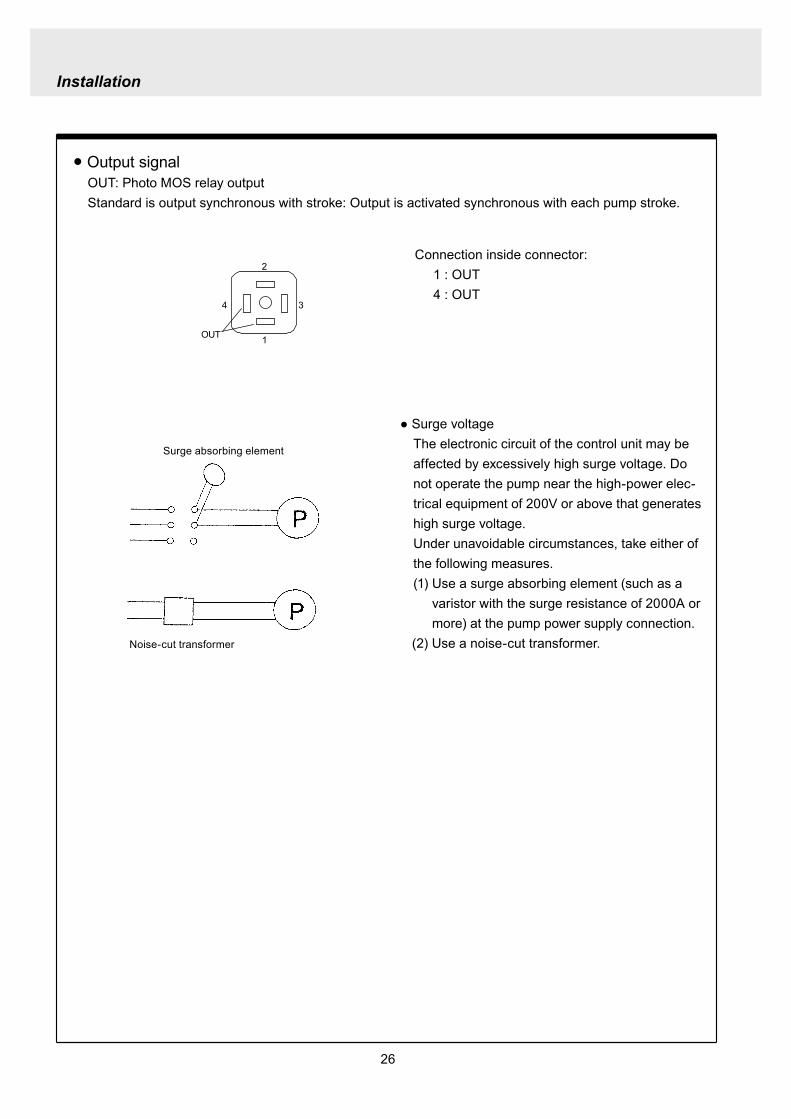
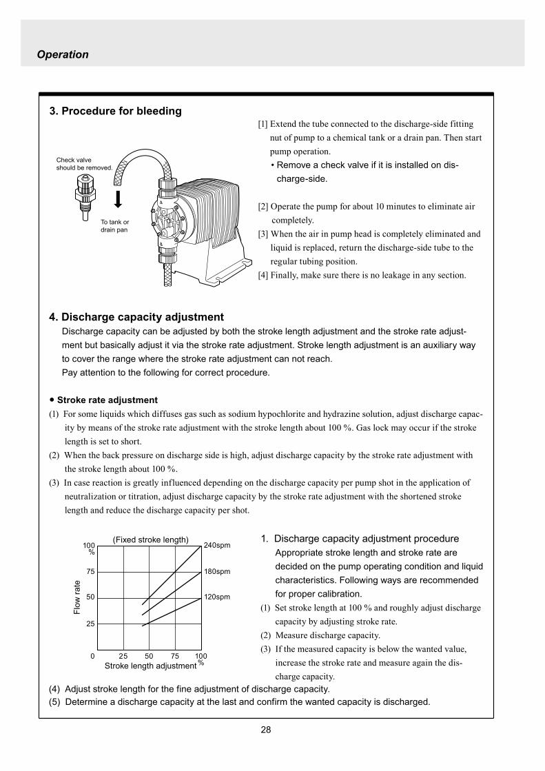
28
3 Procedure for bleeding
Check valve should be removed
To tank or drain pan
100
75
50
25
0 25 50 75 100
(Fixed stroke length)
Stroke length adjustment
240spm
180spm
120spm
Flow
rate
Operation
[1] Extend the tube connected to the discharge-side fitting nut of pump to a chemical tank or a drain pan Then start pump operationbull Remove a check valve if it is installed on dis-
charge-side
[2] Operate the pump for about 10 minutes to eliminate air completely
[3] When the air in pump head is completely eliminated and liquid is replaced return the discharge-side tube to the regular tubing position
[4] Finally make sure there is no leakage in any section
4 Discharge capacity adjustmentDischarge capacity can be adjusted by both the stroke length adjustment and the stroke rate adjust-ment but basically adjust it via the stroke rate adjustment Stroke length adjustment is an auxiliary way to cover the range where the stroke rate adjustment can not reachPay attention to the following for correct procedure
Stroke rate adjustment(1) For some liquids which diffuses gas such as sodium hypochlorite and hydrazine solution adjust discharge capac-
ity by means of the stroke rate adjustment with the stroke length about 100 Gas lock may occur if the stroke length is set to short
(2) When the back pressure on discharge side is high adjust discharge capacity by the stroke rate adjustment with the stroke length about 100
(3) In case reaction is greatly influenced depending on the discharge capacity per pump shot in the application of neutralization or titration adjust discharge capacity by the stroke rate adjustment with the shortened stroke length and reduce the discharge capacity per shot
1 Discharge capacity adjustment procedureAppropriate stroke length and stroke rate are decided on the pump operating condition and liquid characteristics Following ways are recommended for proper calibration
(1) Set stroke length at 100 and roughly adjust discharge capacity by adjusting stroke rate
(2) Measure discharge capacity(3) If the measured capacity is below the wanted value
increase the stroke rate and measure again the dis-charge capacity
(4) Adjust stroke length for the fine adjustment of discharge capacity(5) Determine a discharge capacity at the last and confirm the wanted capacity is discharged
CAUTION
29
100
75
50
25
0 60 120 180 240spm
Fixed stroke length
Stroke rate adjustment
Flow
rate
Screw driverOPEN
LOCK
100
75
50
25
0 25 50 75 100
Fixed stroke rate
Flow
rate
Stroke length adjustment
Operation
2 Stroke rate adjustmentStroke rate is adjusted by the key operations of control unit Control the plunger stroke rate per minute from 1 to 240 spm via control unit
3 Stroke length adjustmentStroke length adjustment knob is locked with a screw Loosen the screw before adjustment and lock it afterwards
(1) Turn on pump and adjust the discharge capacity by turning the stroke length adjusting knob while pump is running
(2) The left graph shows the relation between stroke length and discharge capacity The maximum dis-charge capacity is shown on the name plate
bull The usage between 40 and 100 is practi-cal
Do not turn the stroke length adjusting knob when pump stops
CAUTIONBe sure to tighten the screw on the adjust-ment knob after an adjustment The knob may rotate unintentionally due to a loose fixation This may result in the fluctuation in a discharge rate
30
Mode ParameterDefault value
Setting range Step
Manual operation Stroke speed 240 1-240DIV setting Dividing ratio frasl 1 1-9999
MULT setting Multiply ratio times1 times1-9999ANA R setting 4-20 4-20 20-4 0-20 20-0
ANA V setting
P1 amperage 40 00-200P1 stroke speed 0 0-240P2 amperage 200 00-200P2 stroke speed 240 0-240
User setting
EXT operation ANA V DIV MULT ANA R ANA V
Anti-chatteringMECH MECH ELECST05 ST05 ST20 ST50FT01 FT02 FT04
Buffer memory MEM-N MEM-N MEM-Y
111-
011
011
2 Control unit operationEH-F type pump is controlled by means of setting or changing the setting values of the controller Control functions are various at each operation mode Read this section carefully before operation
Default parameter values
5 Full operationPut pump in use after bleeding and adjusting discharge capacityPump runs in manual operation or in accordance with the setting of control unit
6 Manual operationStarting pump After turning on power ON lamp (Green) appears and display shows WAIT mode For
the first time to turn on power MAN lamp appears and pump starts after pushing STARTSTOP key once
Stop pump Push STARTSTOP key to turn off MAN lamp and stop pump Pump starts and stops every time STARTSTOP key is pressed
7 EXT operationRefer to the next section of 2 Control unit operation
8 Shout down When pump will not in use for a long time (one month or more)
Run pump with clean water about 30 minutes in order to clean the wet-end parts and the inside of pip-ing before storage
When re-starting pump after a long time storage If pump dose not suck up liquid clean valve sets and remove the sticking foreign matters Carry out an air elimination and adjust discharge capacity when air stays inside pump head Refer to page 28 3 Procedure for bleeding
Operation
---
-
31
AN
A V
(Ana
log
var
iabl
e)
DIV
(Pul
se d
ivid
ing)
MU
LT(P
ulse
mul
tiply
)A
NA
R(A
nalo
g ri
gid)
SE
TS
ET
Use
r mod
e
EX
T m
ode
sele
ctio
n
EX
T
EX
TE
XT
EX
TE
XT
EX
T EX
T
EX
T
EX
T
EX
T
EX
T
EX
T
EX
T
EX
T
EX
T
EX
T
EX
T
EX
T
3 sec
onds
or m
ore
Wai
t mod
e
Set
ting
of fi
xatio
n pa
ttern
EX
T m
ode
Man
ual o
pera
tion
Set
ting
of s
troke
num
ber
AN
A R
(Ana
log
rigi
d)M
ULT
(Pul
se m
ultip
ly)
DIV
(Pul
se
div
idin
g)
AN
A V
(Ana
log
var
iabl
e)
anti-
chat
terin
gse
tting
dis
play
Setti
ng o
f div
idin
g ra
tioS
ettin
g of
cou
nt n
umbe
r
Curre
nt va
lue of
P1
Stro
ke nu
mbe
r of P
1
Curre
nt va
lue
of P
2
Stro
ke nu
mbe
r of P
2
EX
T O
pera
tion
Dis
play
EX
T se
tting
mod
e
Buf
fer m
emor
yse
tting
dis
play
Pow
er O
N
spm
MA
Nsp
m
spm
DIV
DIV
SE
TS
ET
MU
LT
MU
LTsp
mA
NA
V
spm
AN
AR
AN
AR
SE
Tm
AS
ET
mA
spm
AN
A
V
P1
mA
SE
T
spm
AN
A
V
P1
AN
AR
SE
Tm
A
AN
AR
SE
Tm
AS
ET
AN
A
V
P 2
SE
T
spm
AN
A
V
P 2
AN
AR
SE
Tm
A
AN
A
V
SE
TS
ET
SE
T
SE
T
SE
T
SE
T
SE
T
SE
T
SE
T
SE
T
SE
TS
ET
1 Overview Operating Scheme
Operation
1 means automatic transfer WAIT mode is selected when the power is switched on for the first time On and after the initial power activation pump restores the previous status right before the power is switched off
2 Regarding MANUAL mode pump starts operation by pushing STARTSTOP key at WAIT modePushing STARTSTOP key again the pump stops and returns to WAIT mode
3 Regarding EXT operation pushing EXT key at WAIT mode the pump moves to EXT mode and starts operationPushing STARTSTOP key stops the operation and returns the pump to WAIT mode
4 The change of each setting of EXT operation is accessible by pushing EXT key at EXT mode Pushing EXT key after the setting pump starts in EXT operation according to the changed setting
5 Pushing EXT key for 3 seconds at WAIT mode pump moves to USER mode At USER mode the EXT mode selection and the detailed setting such as the setting of buffer memory or so can be obtained
For details refer to each section of 2 Pump operation
2 Pump operation1 Operation of controller
Before turning on power confirm the specified power source on the nameplate
CAUTION
Connecting any other powers than the one shown on nameplate to pump is strictly prohibitedIt could lead to pump trouble or failure
Operation
32
1 Turning on powerDisplay shows WAIT mode when pump is turned on for the first time After the initial power activation the pump restores the previous mode right before the power was turned off last time If power is turned off at any setting modes WAIT mode appears at the next power activation
Stroke speed setting value is shown on display at WAIT mode ON lamp lights (Green)
EXT
EH-F ControllerSTARTSTOP
ON STOP
spm
33
2 Manual operation(1) Stroke speed can be adjusted by and
keys The figure changes quickly when either or key is depressed The picture below
shows the stroke speed is set to 160 spm
EXT
EH-F ControllerSTARTSTOP
ON STOP
spm
EXT
EH-F ControllerSTARTSTOP
ON STOP
MAN spm
EXT
EH-F ControllerSTARTSTOP
ON STOP
spm
(2) Push STARTSTOP key once to start the pump operation MAN indication appears and ON lamp blinks synchronously with each stroke
(3) MAN indication disappears and ON lamp stops blinking as STARTSTOP key is pushed again Pump enters WAIT mode
Operation
Operation
34
EXT
EH-F ControllerSTARTSTOP
ON STOP
ANA V
P1 SET mA
EXT
EH-F ControllerSTARTSTOP
ON STOP
P1 SET
ANA V spm
EXT
EH-F ControllerSTARTSTOP
ON STOP
spm
EXT
EH-F ControllerSTARTSTOP
ON STOP
ANA V spm
(4) Set the current value at P1 Figure increases or decreases as or key is pushed The pic-ture below shows 80 mA is set to point 1
EXT
EH-F ControllerSTARTSTOP
ON STOP
ANA V
P1 SET mA
(5) Pushing EXT key once spm appears on the display while mA disappears The picture below shows the number of strokes at P1
EXT
EH-F ControllerSTARTSTOP
ON STOP
P1 SET
ANA V spm
3 EXT operation (ANA V mode)(1) Push STARTSTOP key to move to WAIT mode
if pump is in another mode Go to next step if pump is in WAIT mode
(2) ANAV indication appears and pump enters an EXT mode as EXT key is pushed once Pump starts operation in accordance with current sig-nals and various settings ON lamp blinks at each pumping during operation Pump is con-trolled via the EXT mode which was select-ed at USER mode The initial setting of EXT mode is ANA V mode Select a preferable EXT mode in USER mode The picture below shows ANA V mode (The spm on the display changes according to input signals)
(3) Push EXT key once when pump is running in ANA V mode Display indicates the setting display of ANA V mode spm indication dis-appears and P1 SET and mA indications appear on the screen
(6) Set the number of strokes at P1 Figure increasesdecreases as key is pushed Picture below shows 10 spm is set for point 1
Operation
35
(7) Push EXT key to move to the setting display of the current value at P2 P1 and spm disap-pear and P2 and mA appears instead
EXT
EH-F ControllerSTARTSTOP
ON STOP
ANA V
P 2 SET mA
EXT
EH-F ControllerSTARTSTOP
ON STOP
ANA V
P 2 SET mA
EXT
EH-F ControllerSTARTSTOP
ON STOP
P 2 SET
ANA V spm
(11) Push EXT key to return to EXT mode Pump starts to run in ANA V mode on the setting of (4) through (10) ON lamp starts to blink at each pumping
EXT
EH-F ControllerSTARTSTOP
STOPON
ANA V spm
EXT
EH-F ControllerSTARTSTOP
ON STOP
P 2 SET
ANA V spm
EXT
EH-F ControllerSTARTSTOP
ON STOP
spm
(8) Set the current value of P2 by pushing and keys Picture below shows 180 mA is set to
point2
(9) Pushing EXT key once spm appears on the display while mA disappears The picture below shows the number of strokes at P2
(10) Set the number of strokes at P2 by pushing and keys Picture below shows 200
spm is set to point 2
(12) Pushing STARTSTOP key pump enters WAIT mode and pump stops ON lamp stops blink-ing and ANAV indication disappears
CAUTIONWhen the setting of the buffer memory is OFF keep the number of strokes in the dividing operation 240 spm or below The input signals to operate the pump over 240 spm can cause an unstable pump operationWhen the setting of the buffer memory is ON the pump operates for all the input pulse signalsPump keeps operating after all the signals are stopped in this case Be careful when setting of buffer memory
Operation
36
EXT
EH-F ControllerSTARTSTOP
ON STOP
DIV
SET
EXT
EH-F ControllerSTARTSTOP
ON STOP
DIV
SET
EXT
EH-F ControllerSTARTSTOP
STOPON
DIV spm
EXT
EH-F ControllerSTARTSTOP
ON STOP
spm
(2) Pushing EXT key DIV appears and pump starts operation in the ratio of input pulse sig-nals a pumping ON lamp blinks synchronous-ly at each pumping The initial setting of EXT selection is ANA V mode Change mode to DIV mode via USER mode Refer to P 40 for detail information
(3) Push EXT key while pump is operating in DIV mode Pump stop running and SET indication appears on the DIV setting display in stead of spm indication
(4) Enter a dividing ratioFigure increasesdecreases when key is pushed The picture below shows 10 is set
4 EXT operation (DIV mode)
(1) Push STARTSTOP key to move to WAIT mode if pump is in another mode Go to next step if pump is in WAIT mode
CAUTIONOn condition the setting of buffer memory is OFF do not input any pulse signals during the pumping motions for a input pulse signal in the multiply operation These input pulse signals are cancelledWhen the setting of buffer memory is ON pump operates for all the input pulse signals
Operation
37
EXT
EH-F ControllerSTARTSTOP
ON STOP
spm
EXT
EH-F ControllerSTARTSTOP
STOPON
DIV spm
EXT
EH-F ControllerSTARTSTOP
ON STOP
spm
EXT
EH-F ControllerSTARTSTOP
ON STOP
MULT
(5) Push EXT key to return to EXT operating mode Pump starts to run on the setting at item (4) ON lamp blinks synchronously at each pumping
(6) Pushing STARTSTOP key pump enters WAIT mode and pump stopsDIV indication disappears and ON lamp stops blinking
5 EXT operation (MULT mode)
(2) MULT indication appears and pump starts running in an EXT operation mode in the ratio of an input pulse signal pumpings as press-ing EXT key ON lamp blinks at each pump-ing Display shows the rest of the number of strokes In MULT mode the number of strokes is equal to the setting value in manual opera-tionThe initial setting of the EXT mode selection is ANA V mode which is the operation in pro-portion to current First select MULT mode via USER mode Refer to P 40 for detail informa-tion
(1) Push STARTSTOP key to move to WAIT mode if pump is in another mode Go to next step if pump is in WAIT mode
Operation
38
EXT
EH-F ControllerSTARTSTOP
ON STOP
spmEXT
EH-F ControllerSTARTSTOP
ON STOP
ANAR spm
EXT
EH-F ControllerSTARTSTOP
ON STOP
MULT
SET
EXT
EH-F ControllerSTARTSTOP
ON STOP
MULT
EXT
EH-F ControllerSTARTSTOP
ON STOP
spm
EXT
EH-F ControllerSTARTSTOP
ON STOP
MULT
SET
(5) Push EXT key to return to MULT mode(3) Pushing EXT key when pump is running in the multiply operation calls the setting display of MULT mode and SET indication appearsPump stops running and ON lamp stop blinking
(4) Enter the number of pumpings per input signalFigure increasesdecreases when key is pushed The picture below shows the pump-ing number is set to 1800 times per an input signal
6 EXT operation (ANA R mode)(1) Push STARTSTOP key to move to WAIT mode
if it is in another mode Go to next step if it is in WAIT mode
(6) Pushing STARTSTOP key recalls WAIT mode and pump stops spm indication appears in stead of MULT indication
(2) Pushing EXT key ANAR appears and pump starts running in the ratio of an input pulse sig-nal pumpings ON lamp blinks at each pump-ing The initial setting of the EXT mode selec-tion is ANA V mode which is the operation in proportion to current is selected First select ANA R mode in USER mode Refer to P 40 for more information
Operation
39
EXT
EH-F ControllerSTARTSTOP
ON STOP
ANAR
SET mA
EXT
EH-F ControllerSTARTSTOP
ON STOP
ANAR spm
EXT
EH-F ControllerSTARTSTOP
ON STOP
ANAR
SET mA
EXT
EH-F ControllerSTARTSTOP
ON STOP
spm
(4) Figure increasesdecreases when key is pushed The picture below is when it is set to 0-240 spm for 20-4 mA
(5) Push EXT key to return to EXT mode Pump starts to run on the setting at item (4) ON lamp blinks synchronously at each pumping
(6) When pushing STARTSTOP key pump enters WAIT mode and stops running ON lamp stops blinking and ANAR disappears
(3) Pushing EXT key when pump is running in the multiply operation calls the setting display of ANAR mode and SET and mA indications appear while spm disappears Pump stops running and ON lamp stops blinking
Operation
40
EXT
EH-F ControllerSTARTSTOP
ON STOP
ANA V
(5) Push EXT key to confirm the desired EXT mode Pump displays the EXT mode selection The picture below shows DIV appears to indi-cate DIV mode is selected
EXT
EH-F ControllerSTARTSTOP
ON STOP
DIV
EXT
EH-F ControllerSTARTSTOP
ON STOP
SET
EXT
EH-F ControllerSTARTSTOP
ON STOP
spm
EXT
EH-F ControllerSTARTSTOP
ON STOP
spm
EXT
EH-F ControllerSTARTSTOP
ON STOP
SET
7 USER settingThe setting of each function is changed in USER mode Have the pump entering WAIT mode in order to move to USER mode OUT (Output) is synchronous with spm and it can not be changed
7-1 EXT mode selection Any one of DIV (pulse dividing) MULT (pulse multiply) ANAR (analog rigid) or ANAV (analog vari-able) can be active in EXT mode The initial mode when shipped from factory is ANAV
(1) Push STARTSTOP key to move to WAIT mode if it is in another mode If it is in WAIT mode go to next step
(2) Press EXT key for more than 3 seconds to move to USER mode The picture below shows pump enters the EXT mode selection
(3) Pushing EXT key SET appears and display shows the mode currently set Picture below shows ANA V mode is selected
(4) Push or key to select a desired EXT mode The picture below shows DIV mode is selected
(6) Push STARTSTOP key to move to WAIT mode spm appears while DIV goes out
Operation
41
EXT
EH-F ControllerSTARTSTOP
ON STOP
spm
EXT
EH-F ControllerSTARTSTOP
ON STOP
ANA V
EXT
EH-F ControllerSTARTSTOP
ON STOP
SET
(3) Push key once
EXT
EH-F ControllerSTARTSTOP
ON STOP
(4) Push key again to move to the anti-chatter-ing setting display
EXT
EH-F ControllerSTARTSTOP
ON STOP
(5) Pushing EXT key display shows the mode cur-rently set and SET appears on it The picture below shows when MECH is selected
EXT
EH-F ControllerSTARTSTOP
ON STOP
SET
7-2 Setting of anti-chattering Anti-chattering function is settable against the incoming pulses during the DIV or MULT operation For the long chattering of mechanical contact such as relay set a large figure via MECH For the high speed (high frequency) chattering of the semi-conductor type contact such as transistor set a small figure via ELEC ST05 of MECH is initial setting
(6) Select MECH by or key for a mechani-cal contact And select ELEC for a semi-conductor contact The picture below shows ELEC is selected
(1) Push STARTSTOP key to move to WAIT mode if it is in another mode If it is in WAIT mode go to next step
(2) Press EXT key for more than 3 seconds to move to USER mode The picture below shows pump enters the EXT mode selection
Operation
42
EXT
EH-F ControllerSTARTSTOP
ON STOP
SET
(7) Push EXT key to display the current set state The picture below shows FT01 is selected
EXT
EH-F ControllerSTARTSTOP
ON STOP
SET EXT
EH-F ControllerSTARTSTOP
ON STOP
EXT
EH-F ControllerSTARTSTOP
ON STOP
spm
7-3 Setting of buffer memoryIn case pump operation can not catch up with the input pulse signals in DIV or MULT operation exces-sive pulse signals can be put in memory up to 65535 pulses However the excessive pulses can not be restored if once power is off or mode is changed
EXT
EH-F ControllerSTARTSTOP
ON STOP
spm
(2) Press EXT key for 3 seconds or more to move to USER mode The picture below shows the EXT mode selection display
EXT
EH-F ControllerSTARTSTOP
ON STOP
ANA V
(8) Set a large figure for the long chattering by or key and set a small figure for high speed (high frequency) chattering The picture below shows FT04 is selected
(9) Push EXT key to return to the anti-chattering setting display SET indication disappears
(10) Push STARTSTOP key to return to wait mode spm indication appears
(1) Push STARTSTOP key to move to WAIT mode if it is in another mode If it is in WAIT mode go to next
Operation
43
(3) Push key once
EXT
EH-F ControllerSTARTSTOP
ON STOP
(7) Push or key in order to set buffer memo-ry to ON or OFF Select MEM-Y to set it ON Select MEM-N for OFF setting The picture below shows when ON is set
EXT
EH-F ControllerSTARTSTOP
ON STOP
SET
(4) Push key once again
EXT
EH-F ControllerSTARTSTOP
ON STOP
(8) Push EXT key to return to the buffer memory setting display SET indication disappears
EXT
EH-F ControllerSTARTSTOP
ON STOP
(9) Push STARTSTOP key to return to WAIT mode spm indication appears
EXT
EH-F ControllerSTARTSTOP
ON STOP
spm
(5) Push key once again and the buffer memory setting display is shown
EXT
EH-F ControllerSTARTSTOP
ON STOP
(6) Push EXT key in order to display the current set state SET indication appears The picture below shows the buffer memory is set to OFF
EXT
EH-F ControllerSTARTSTOP
ON STOP
SET
Operation
44
8 Bleeding amp self-primingAt WAIT mode Manual operating mode and EXT operating mode pump operates at max speed tak-ing priority over any functions when both and keys are pushed at once Pump runs at max speed only when both keys are depressed Pump state returns to the previous mode once either or key is released Pressing and keys for 10 seconds keeps pump running at maximum speed In this state this fixation is released when pushing either or key once and pump returns to the previous mode
(1) When pump is running in ANAV mode
EXT
EH-F ControllerSTARTSTOP
ON STOP
ANA V spm
(2) Pump start to run at full speed when and keys are pressed at once Display shows
PRIME If either or key is released pump returns to the previous mode In this case pump returns to ANAV mode
EXT
EH-F ControllerSTARTSTOP
ON STOP
ANA V
(3) Pressing both and keys simultaneously for 10 seconds or more pump continues to run at full speed even if both keys are released In this case indication appearsPush either or key to release this state indication disappears and pump returns to the previous mode In this case pump returns to ANAV mode
EXT
EH-F ControllerSTARTSTOP
ON STOP
ANA V
Operation
45
10 Error display and release(1) In case Input signals fall to 4 mA or below while
4-20 or 20-4 is set to ANA R mode pump stops with DISCN blinking and Err on dis-play
(2) This error state can be released by push-ing STARTSTOP key and pumps enters wait mode In this case check the wiring and input signals
EXT
EH-F ControllerSTARTSTOP
ON STOP
ANAR
Err
spm
EXT
EH-F ControllerSTARTSTOP
ON STOP
spm
9 Key lockKey lock function is to prevent pump from being operated by some other person than user If STARTSTOP key is pressed for five seconds or more when pump is running or stops all key operations become ineffective with LOCK indication on display This function can be released by pressing STARTSTOP key for 5 seconds while LOCK lights
EXT
EH-F ControllerSTARTSTOP
ON STOP
MAN spm
LOCK
46
Do not conduct a maintenance work with the wet hands It can cause an electric shock
Before dismantling pump be sure to turn off power and check the pump is not electrified Do not
start a dismantlement work after stopping the pump by pushing the STARTSTOP key only Put up
the sign of ldquoMaintenance work is in progressrdquo in order to prevent a pump switch from turning on
unintentionally during the work Release the pressure of discharge piping and drain the liquid from
the wet end parts And then clean the inside of pump head
Wear protective clothing such as a protective mask globes goggles and chemical-proof wear
according to the handled chemical liquid during the work
WARNING
5 Maintenance
1 Trouble shootingTrouble Cause Troubleshooting
Pump dose not start Faulty wiring or disconnection in wiring Voltage is too low Failure in the electronic circuit of control unit
Pump dose not suck liquidDischarge amount is low
Air suction from suction piping Valve gasket is not installed Valve set assembling direction is wrong Pump is air-locked Pump stroke length is too short Suction-sidedischarge-side valve is clogged with
foreign matter Adhesion of valve onto valve seat
Discharge amount fluctuates
Liquid leaks
Key operation is ineffective Key is locked Release key lock
Pump doesnt run
Pump is in waiting mode Signals are not coming for EXT operation Pump is in EXT setting mode Pump is suspended with STOP
Move to operation mode Check wiring and correct the wrong part Move to EXT operating mode Release STOP function
Abnormal noise
Suction-sidedischarge-side valve is clogged with foreign matters
The sound absorption gasket is worn out Bearing is worn out Spring is damaged
Piping vibrates due to pulsation Bearing is worn out Spring is damaged
Install a accumulator or an air chamber The end of pump life span The end of pump life span
Suction-sidedischarge-side valve is clogged with foreign matters
Air is trapped in pump Overfeeding Diaphragm is damaged
Fittings are not tightly closed Pump head is not tightened Diaphragm is damaged O ring and valve gasket are not installed O ring is damaged
Correct wiring Inspect power source and provide measurement Replace the whole unit
Arrange piping again Install valve gasket Reassemble valve set Carry out air elimination Drive pump with 100 stroke length to prime liquid Then
reset stroke length Disassemble inspect and clean Disassemble inspect and clean
Tighten fittings Tighten pump head Replace diaphragm Install O ring and valve gasket Replace O ring
Disassemble inspect and clean
Carry out air elimination Install a check valve or a back pressure valve Replace diaphragm
Disassemble inspect and clean
The end of pump life span The end of pump life span The end of pump life span
Abnormal vibration
Input pulse can not be read Signals are not coming Anti-chattering setting is not proper
Check wiring and correct the wrong part Change the setting properly
Analog signal input can not be read
Wrong wiring Signals are over acceptable loaded resistance
Check wiring and correct wrong part The load resistance is 200Ω Use some devise which can
accept the load resistance
47
CAUTION Check periodically whether the bolts fixing pump head are tightened Tighten them as needed
The bolts fixing pump head may loosen in operation Tightening torque 255Nbullm
Maintenance
3
bull Tighten joint where leakage has occurredbull The excessive air bubbles in the discharged liquid mean air suc-
tion has been caused in system Examine the piping and tighten joint on where leaks
Is there liquid leakage or air suction at any joints on pump or piping
2 Maintenance and inspection
1 Daily inspectionPay attention to the following points during pump operation Stop pump immediately upon detecting abnormality and take measures according to the item Troubleshooting When wear parts come to the life time replace them by new ones
No
1
2
Check Point Description
Does pump lift liquid normally
bull Is liquid normally fedbull Is suction pressuredischarge pressure at normal levelbull Has liquid undergone quality change crystallization or solidifica-
tion
Abnormal noise or vibrationbull Abnormal noise or vibration may happen from the abnormal func-
tioning of pump
EXT setting can not be stored
After EXT setting STARTSTOP key is pushed for EXT by mistake
Push EXT key to operate pump in EXT mode
ldquoPRIME is kept indicated and other operations are inac-cessible
Self-priming function is active Push either or key to release the function
Analog signal input can not be read and DISCN indication appears
Wrong wiring or disconnection Check wiring and correct the wrong part Refer to page 45
for how to release an error indication
Trouble Cause Troubleshooting
48
Maintenance
2 Wear partsWear parts should be replaced in proper period for a long period of pump operation It is recommended that follow-ing parts are always ready for the replacementVC V6 PC P6 types
Parts Qty Life span
Pum
p he
ad
Valve set
EH-F35 EH-F45 EH-F55middot70
2sets
8000hours
Diaphragm 1
Refer to exploded view
Bac
k pr
essu
re v
alve
1
2
Che
ck v
alve
7 6 1
8 11 1
Diaphragm seat 1
O ring
Poppet check valve (With check gasket)
Check valve spring Spacer
Diaphragm
O ring
Note Durability of wear parts depend on the pumped liquid temperature and pressure Time to be replaced mentioned as above is the estimation obtained by continuous pump-ing of clean water at ambient temperature
8000hours
4000hours
49
3 Dismantlement and assembly
Getting wet with or coming in contact with chemicals and toxic liquid is harmful Wear protective clothing such as a protective mask globes goggles and chemical-proof wear during the work
Risk of electrical shock Be sure to turn off power and confirm that pump and devices are not electrified before the work
Release the pressure inside pump and a discharge hose by opening an air bleed valve on piping prior to loosening the piping connections or the dismantlement of pump Dismantlement with the pressure inside pump could lead to liquid spillage
Be careful not to touch residual liquid when dismantling pump Some liquids are harmful for skin or component parts Wipe off liquid when the hand or the component parts come in contact with liquid
WARNING
CAUT ION
Hose
Hose stopperFitting spacer
O ring
Fitting nut
Fitting
Pumphead
Remove the fittingwith a spanner
1 Valve set replacement Dismantlement1 Loosen a fitting nut and remove the hose con-
nected to pump head Pay attention to the liquid dripping
2 Loosen a fitting with a spanner to remove it Then detach the valve set from pump head
Maintenance
50
AssemblyAssembly procedure is in reverse order to disas-sembly Pay attention to the following when assembling valve set DispositionInsertion direction of valve set The wrong dispositioninsertion direction of valve
set component can lead to leakage and less dis-charge amount
O ring is fitted properly1 Discharge side valve set mounting
Put valve set in pump head and screw a fitting into a pump head by hand and then re-tighten it by 14 turns with a spanner
2 Suction side valve set mountingPut valve set in connection port and screw the fitting into pump head by hand and then re-tighten it by 14 turns with spanner
Note Pay attention to the mounting direction of the spacer fitted to EH-F45(VC V6 PC)Make sure the cut portion on the spacer of suction side should be downward the one of discharge side should be upward
Suction side
Discharge side
O ringValve gasket
Valve gasket
Valve gasket
Valve guideValveValve seatSpacer
O ring
Valve gasketValve guideValveValve seat
Spacer
1714
11
1312
11
1312
17
17
14
14
14
11
31
1312
31
17
14
11
1312
12
13
11
14
EH-F35
EH-F45
EH-F5570
Suct
ion
side
Dis
char
ge s
ide
For b
oth
suct
ion
and
disc
harg
e si
deFo
r bot
h su
ctio
nan
d di
scha
rge
side
VC V6 PC P6 Type
Maintenance
51
Pay attention not to lose diaphragm spacer and to apply the correct number of diaphragm spacers 0 to several pieces of diaphragm spacers are put between retainer and plunger to adjust the position of diaphragm The number of spacers mounted depends on the pump model There are the models which do not have spacers
Maintenance
2 Diaphragm replacement Dismantlement1 Set stroke length to 0 by adjusting stroke length
adjustment knob
2 Remove the pump head from the pump body by loos-ening hex socket cap bolts
3 Rotate a diaphragm anti-clockwise to remove it from a plunger pin The diaphragm is screwed into the plunger pin
AssemblyAssembly is done in reverse order to disassembly Follow the steps below1 Make sure the stroke length of pump is set to 0
prior to an assembly Operate pump to set the stroke length to 0 and
stop it Then turn off power
2 Fit a rear diaphragm seat a retainer and a diaphragm spacer into new diaphragm via the threaded pin and screw the diaphragm into the plunger pin
Fit the concave side of retainer into the convex side of diaphragm Pay attention the retainer dose not come off
3 Set the stroke length to 100 Operate pump to set the stroke length to 100
and stop it Then turn off power4 Install a pump head to a pump body by tightening
the hex sock cap bolts equally Tightening torque is 255Nbullm
52
4 Accessories1 Connection port bore bull Check valve bull Back pressure valve
Note1 Check valves and back pressure valves are options2 Regarding the connection of the discharge side of back pressure valve
NPT38 and NPT12 taper pipe thread is used for BV-N-CR
Pump type Connection port bore Check valve Back pressure valve
EH-F35VC empty38timesempty12 hose CA-3VCH-C6 ndash
empty38timesempty12 hose CA-3VEH-C6 ndashempty38timesempty12 hose CA-3VH-C6 ndashempty38timesempty12 hose CA-3VCH-C6 ndashempty38timesempty12 hose CA-3VEH-C6 ndashempty38timesempty12 hose CA-3VH-C6 ndash
V6
empty38timesempty12 hose ndash BV-3NV-C6Rempty38timesempty12 hose ndash BV-3NE-C6Rempty38timesempty12 hose ndash BV-3NPV-C6Rempty58timesempty34 hose ndash BV-3NV-C7Rempty58timesempty34 hose ndash BV-3NE-C7Rempty58timesempty34 hose ndash BV-3NPV-C7R
PC
EH-F45VCV6PC
EH-F55VCV6PC
EH-F70VCV6PC
Maintenance
53
Maintenance
5 Exploded view
1 General view The extent of dismantlement is within the following exploded view
Diaphragm spacer
Retainer
(Back up retainer)55 bull 70 types
Pump body
Valve set
Valve set
Pump head
Diaphragm
Rear diaphragm sheet
54
2 Pump head (Hose connection type)
EH-F45 type EH-F35 type
4
28
2930
3
1114
131211
131217
1897
1
17
111312111312
3
3029
28
4
1920
1920 21
17
111312
31
3
3029
28
4
131217
189
7
11
3114
14
4
282930
3
1
21
1515
EH-F55 type
4
28
2930
3
11
131217
18
9
7
10
1
1920 21
17
111312
3
30
29
28
4
EH-F70 type
4
28
2930
3
14
11131217
18
9
7
10
1
1920 21 17
111312
3
30
29
28
4
15 15
14
1414
14
14 14
Note1 The back up retainer of No10 is only for EH-F55 bull 70 typesNote2 The figure inside ( ) in the above table is for EH-F45 bull 55 bull 70 typesNote3 The number of the diaphragm spacers (No18) is not constant None or a few spacers is inserted at
each diaphragmNote4 The figure inside ( ) in the above table is for EH-F70Note5 EH-F35 bull 55 bull 70 (VC V6 PC ) types require 2 valve gaskets and EH-F45 (VC V6 PC) types
require 4 of themNote6 The spacer on No31 is for EH-F45 type only
No Name Qty1 Pump head 13 Fitting 24 Fitting nut 27 Diaphragm 19 Retainer 110 Back up retainer 1 Note111 Valve guide 4 (2) Note212 Valve seat13 Valve14 Valve gasket
No Name Qty
17 O ring 218 Diaphragm spacer 1 Note319 Hex socket head bolt 6 (8) Note420 Spring washer21 Plain washer28 Hose stopper 229 Fitting spacer 230 O ring 231 Spacer 2 Note6
15 Rear diaphragm seat 1
2 (4) Note54 (2) Note24 (2) Note2
6 (8) Note46 (8) Note4
Maintenance
55
Maintenance
3 Pump head (Flange connection type) EH-F55 type
30
3
11
131217
18
9
7
10
1
1920 21
17
11
1312
3
30
EH-F70 type
15
EH-F45 type EH-F35 type
30
3
11131211
131217
1897
1
17
11131211
1312
3
30
1920
1920 21
17
111312
31
3
131217
189
7
11
31
30
3
1
30
21
1515
30
3
11131217
18
9
7
10
1
1920 21 17
11
1312
3
30
15
32
33
33
32
4
32
433
43332
32
334
43332
32
33
32
334
44
1414
14 14 14
1414
14
14 14
NoNo Name Qty1 Pump head 13 Fitting 24 Fitting nut 27 Diaphragm 19 Retainer 110 Back up retainer 1 Note111 Valve guide 4(2)Note212 Valve seat 4(2)Note213 Valve 4(2)Note214 Valve gasket 2(4)Note5
Name Qty
17 O ring 218 Diaphragm spacer 1 Note319 Hex socket cap bolt 6(8)Note420 Spring washer 6(8)Note421 Plain washer 6(8)Note430 O ring 2
33 Union 2
31 Spacer 2 Note6
15 Rear diaphragm seat 1
32 Flange 2
Note1 The back up retainer of No10 is only for EH-F55 bull 70 typesNote2 The figure inside ( ) in the above table is for EH-F45 bull 55 bull 70 typesNote3 The number of the diaphragm spacers (No18) is not constant None or a few spacers is inserted at
each diaphragmNote4 The figure inside ( ) in the above table is for EH-F70Note5 EH-F35 bull 55 bull 70 (VC V6 ) types require 2 valve gaskets and EH-F45 (VC V6) types require 4 of
themNote6 The spacer on No31 is for EH-F45 type only
56
4 Pump head (Flange connection horizontal suction port type) EH-F55 type
30
3
11
131217
18
9
7
10
1
1920 21
17
111312
3
30
EH-F70 Type
15
EH-F45 Type EH-F35 type
30
3
11131211
131217
1897
1
17
111312111312
3
30
1920
1920 21
17
11131231
3
131217
189
7
11
31
30
3
1
30
21
1515
30
3
11131217
18
9
7
10
1
1920 21 17
111312
3
30
15
32
33
32
433
43334
32
32
334
43334
32
33
44
34
32
334
34
32
334
32
35 353535
1414
14 14 14
1414
14
14 14
No Name Qty1 Pump head 13 Fitting 24 Fitting nut 27 Diaphragm 19 Retainer 110 Back up retainer 1 Note111 Valve guide 4 (2) Note212 Valve seat13 Valve
15 Rear diaphragm sheet 114 Valve gasket
No Name Qty
18 Diaphragm spacer 1 Note319 Hex socket cap bolt20 Spring washer21 Plain washer
31 Spacer 2 Note6
35 Pipe 1
32 Flange 2
34 Elbow 133 Union 2
17 O ring 2
30 O ring 2
4 (2) Note24 (2) Note22 (4) Note5
6 (8) Note4
4 (2) Note24 (2) Note2
Maintenance
Note1 The back up retainer of No10 is only for EH-F55 bull 70 typesNote2 The figure inside ( ) in the above table is for EH-F45 bull 55 bull 70 typesNote3 The number of the diaphragm spacers (No18) is not constant None or a few spacers is inserted at
each diaphragmNote4 The figure inside ( ) in the above table is for EH-F70Note5 EH-F35 bull 55 bull 70 (VC V6) types require 2 valve gaskets and EH-F45 (VC V6) types require 4 of
themNote6 The spacer on No31 is for EH-F45 type only
57
5 Check valve CA-3 type
1 2 3 4 5 6 7 8 11 9 10
16
14
13
15
12
3
15
17
16
1110
98
7
1
54
2
6
14
13
6 Back pressure valve BV-3N-R type
No No Name Qty10 Stopper 111 Diaphragm 112 Lower case 113 Fitting spacer Hose port 114 Hose stopper Ferrule 115 O ring 216 Nut 217 Fitting 1
Name Qty1 Upper case 12 Hexhead bolt (with PW SW) 43 Hex nut 44 Adjusting bolt 15 Hexnut 16 Plain washer 1
8 Spring 19 Retainer plate 1
7 Spring seat 1
NoNo Name Qty1 Fitting nut 12 Hose stopper 13 Fitting spacer 14 O ring 15 Valve case 16 Gasket 1
Name Qty7 Poppet valve 18 Spring 19 O ring 110 Valve fitting 111 Spacer 1
Maintenance
58
Maintenance
1 Outer dimension (Hose connection type) EH-F35 type
TUBING(38rdquotimes12rdquo)
38rdquotimes12rdquo
EH-F45 type
38rdquotimes12rdquo
38rdquotimes12rdquo
59
EH-F55 type
58rdquotimes34rdquo
58rdquotimes34rdquo
EH-F70 type
Maintenance
38rdquotimes12rdquo
38rdquotimes12rdquo
60
Maintenance
2 Outer dimension (Flange connection type) EH-F35 type
EH-F45 type
61
EH-F55 type
EH-F70 type
Maintenance
62
Maintenance
3 Outer dimension (Flange connection horizontal suction port type) EH-F35 type
EH-F45 type
63
EH-F55 type
EH-F70Type
Maintenance
httpwwwiwakipumpsjp
Read this manual before use of product
IWAKIElectromagnetic Metering Pump
EH-F series (North America)
Instruction ManualT596 0706
GermanyItalyDenmarkSwedenFinlandNorwayFranceUKSwitzerlandAustriaHollandSpainBelgiumUSA
TEL (49)2154 9254 0TEL (39)02 990 3931TEL (45)48 24 2345TEL (46)8 511 72900TEL (358)9 2742714TEL (47)66 81 16 60TEL (33)1 69 63 33 70TEL (44)1743 231363TEL (41)26 674 9300TEL (43)2236 33469TEL (31)297 241121TEL (34)943 630030TEL (32)1367 0200TEL (1)508 429 1440
AustraliaSingaporeIndonesiaMalaysiaTaiwanThailandHong KongChinaChinaChinaChinaPhilippinesKoreaVietnam
TEL (61)2 9899 2411TEL (65)6316 2028TEL (62)21 690 6606TEL (60)3 7803 8807TEL (886)2 8227 6900TEL (66)2 322 2471TEL (852)2 607 1168TEL (86)750 380 9018TEL (86)20 8435 0603TEL (86)10 6442 7713TEL (86)21 6272 7502TEL (63)2 888 0245TEL (82)2 3474 0523TEL (84)613 933456
IWAKI EUROPE GmbH IWAKI Italia SRL IWAKI Nordic AS IWAKI Sverige AB IWAKI Suomi Oy IWAKI Norge AS IWAKI France SA IWAKI PUMPS (UK) LTD IWAKI (Schweiz) AG IWAKI (Austria) GmbH IWAKI Holland BV IWAKI Iberica Pumps SA IWAKI Belgium nv IWAKI America Incorporated
FAX 2154 1028FAX 02 990 42888FAX 48 24 2346FAX 8 511 72922FAX 9 2742715FAX 66 81 16 61FAX 1 64 49 92 73FAX 1743 366507FAX 26 674 9302FAX 2236 33469FAX 297 273902FAX 943 628799FAX 1367 2030FAX 508 429 1386
IWAKI Pumps Australia Pty Ltd IWAKI Singapore Pte Ltd IWAKI Singapore (Indonesia Branch) IWAKIm Sdn Bhd IWAKI Pumps Taiwan Co Ltd IWAKI (Thailand) CoLtd IWAKI Pumps Co Ltd IWAKI Pumps (Guandong) Co Ltd GFTZ IWAKI Engineering amp Trading (Guangzhou) IWAKI Pumps Co Ltd (Beijing) IWAKI Pumps (Shanghai) Co Ltd IWAKI Chemical Pumps Philippines Inc IWAKI Korea CoLtd IWAKI Pumps Vietnam Joint Venture CoLtd
FAX 2 9899 2421FAX 6316 3221FAX 21 690 6612FAX 3 7803 4800FAX 2 8227 6818FAX 2 322 2477FAX 2 607 1000FAX 750 380 9078FAX 20 8435 9181FAX 10 6442 7712FAX 21 6272 6929FAX 2 843 3096FAX 2 3474 0221FAX 613 933399
( )Country codes
IWAKI COLTD 6-6 Kanda-Sudacho 2-chome Chiyoda-ku Tokyo 101-8558 JapanTEL(81)3 3254 2935 FAX3 3252 8892(httpwwwiwakipumpsjp)
This is patent pending product
- 107
- 47
- 48
- 49
- 50
- 3
- 4
- 64
- 102
- 101
- 78
- 79
- 91
- 81
- 100
- 99
- 84
- 86
- 85
- 87
- 22
- 23
- 73
- 72
- 26
- 98
- 28
- 27
- 31
- 32
- 29
- 30
- 95
- 34
- 33
- 96
- 35
- 36
- 37
- 38
- 40
- 39
- 41
- 42
- 59
- 58
- 45
- 7
- 6
- 46
- 5
- 8
- 9
- 74
- 75
- 10
- 11
- 61
- 60
- 15
- 14
- 62
- 63
- 16
- 17
- 18
- 19
- 92
- 94
- 93
- 103

CAUTION
29
100
75
50
25
0 60 120 180 240spm
Fixed stroke length
Stroke rate adjustment
Flow
rate
Screw driverOPEN
LOCK
100
75
50
25
0 25 50 75 100
Fixed stroke rate
Flow
rate
Stroke length adjustment
Operation
2 Stroke rate adjustmentStroke rate is adjusted by the key operations of control unit Control the plunger stroke rate per minute from 1 to 240 spm via control unit
3 Stroke length adjustmentStroke length adjustment knob is locked with a screw Loosen the screw before adjustment and lock it afterwards
(1) Turn on pump and adjust the discharge capacity by turning the stroke length adjusting knob while pump is running
(2) The left graph shows the relation between stroke length and discharge capacity The maximum dis-charge capacity is shown on the name plate
bull The usage between 40 and 100 is practi-cal
Do not turn the stroke length adjusting knob when pump stops
CAUTIONBe sure to tighten the screw on the adjust-ment knob after an adjustment The knob may rotate unintentionally due to a loose fixation This may result in the fluctuation in a discharge rate
30
Mode ParameterDefault value
Setting range Step
Manual operation Stroke speed 240 1-240DIV setting Dividing ratio frasl 1 1-9999
MULT setting Multiply ratio times1 times1-9999ANA R setting 4-20 4-20 20-4 0-20 20-0
ANA V setting
P1 amperage 40 00-200P1 stroke speed 0 0-240P2 amperage 200 00-200P2 stroke speed 240 0-240
User setting
EXT operation ANA V DIV MULT ANA R ANA V
Anti-chatteringMECH MECH ELECST05 ST05 ST20 ST50FT01 FT02 FT04
Buffer memory MEM-N MEM-N MEM-Y
111-
011
011
2 Control unit operationEH-F type pump is controlled by means of setting or changing the setting values of the controller Control functions are various at each operation mode Read this section carefully before operation
Default parameter values
5 Full operationPut pump in use after bleeding and adjusting discharge capacityPump runs in manual operation or in accordance with the setting of control unit
6 Manual operationStarting pump After turning on power ON lamp (Green) appears and display shows WAIT mode For
the first time to turn on power MAN lamp appears and pump starts after pushing STARTSTOP key once
Stop pump Push STARTSTOP key to turn off MAN lamp and stop pump Pump starts and stops every time STARTSTOP key is pressed
7 EXT operationRefer to the next section of 2 Control unit operation
8 Shout down When pump will not in use for a long time (one month or more)
Run pump with clean water about 30 minutes in order to clean the wet-end parts and the inside of pip-ing before storage
When re-starting pump after a long time storage If pump dose not suck up liquid clean valve sets and remove the sticking foreign matters Carry out an air elimination and adjust discharge capacity when air stays inside pump head Refer to page 28 3 Procedure for bleeding
Operation
---
-
31
AN
A V
(Ana
log
var
iabl
e)
DIV
(Pul
se d
ivid
ing)
MU
LT(P
ulse
mul
tiply
)A
NA
R(A
nalo
g ri
gid)
SE
TS
ET
Use
r mod
e
EX
T m
ode
sele
ctio
n
EX
T
EX
TE
XT
EX
TE
XT
EX
T EX
T
EX
T
EX
T
EX
T
EX
T
EX
T
EX
T
EX
T
EX
T
EX
T
EX
T
EX
T
3 sec
onds
or m
ore
Wai
t mod
e
Set
ting
of fi
xatio
n pa
ttern
EX
T m
ode
Man
ual o
pera
tion
Set
ting
of s
troke
num
ber
AN
A R
(Ana
log
rigi
d)M
ULT
(Pul
se m
ultip
ly)
DIV
(Pul
se
div
idin
g)
AN
A V
(Ana
log
var
iabl
e)
anti-
chat
terin
gse
tting
dis
play
Setti
ng o
f div
idin
g ra
tioS
ettin
g of
cou
nt n
umbe
r
Curre
nt va
lue of
P1
Stro
ke nu
mbe
r of P
1
Curre
nt va
lue
of P
2
Stro
ke nu
mbe
r of P
2
EX
T O
pera
tion
Dis
play
EX
T se
tting
mod
e
Buf
fer m
emor
yse
tting
dis
play
Pow
er O
N
spm
MA
Nsp
m
spm
DIV
DIV
SE
TS
ET
MU
LT
MU
LTsp
mA
NA
V
spm
AN
AR
AN
AR
SE
Tm
AS
ET
mA
spm
AN
A
V
P1
mA
SE
T
spm
AN
A
V
P1
AN
AR
SE
Tm
A
AN
AR
SE
Tm
AS
ET
AN
A
V
P 2
SE
T
spm
AN
A
V
P 2
AN
AR
SE
Tm
A
AN
A
V
SE
TS
ET
SE
T
SE
T
SE
T
SE
T
SE
T
SE
T
SE
T
SE
T
SE
TS
ET
1 Overview Operating Scheme
Operation
1 means automatic transfer WAIT mode is selected when the power is switched on for the first time On and after the initial power activation pump restores the previous status right before the power is switched off
2 Regarding MANUAL mode pump starts operation by pushing STARTSTOP key at WAIT modePushing STARTSTOP key again the pump stops and returns to WAIT mode
3 Regarding EXT operation pushing EXT key at WAIT mode the pump moves to EXT mode and starts operationPushing STARTSTOP key stops the operation and returns the pump to WAIT mode
4 The change of each setting of EXT operation is accessible by pushing EXT key at EXT mode Pushing EXT key after the setting pump starts in EXT operation according to the changed setting
5 Pushing EXT key for 3 seconds at WAIT mode pump moves to USER mode At USER mode the EXT mode selection and the detailed setting such as the setting of buffer memory or so can be obtained
For details refer to each section of 2 Pump operation
2 Pump operation1 Operation of controller
Before turning on power confirm the specified power source on the nameplate
CAUTION
Connecting any other powers than the one shown on nameplate to pump is strictly prohibitedIt could lead to pump trouble or failure
Operation
32
1 Turning on powerDisplay shows WAIT mode when pump is turned on for the first time After the initial power activation the pump restores the previous mode right before the power was turned off last time If power is turned off at any setting modes WAIT mode appears at the next power activation
Stroke speed setting value is shown on display at WAIT mode ON lamp lights (Green)
EXT
EH-F ControllerSTARTSTOP
ON STOP
spm
33
2 Manual operation(1) Stroke speed can be adjusted by and
keys The figure changes quickly when either or key is depressed The picture below
shows the stroke speed is set to 160 spm
EXT
EH-F ControllerSTARTSTOP
ON STOP
spm
EXT
EH-F ControllerSTARTSTOP
ON STOP
MAN spm
EXT
EH-F ControllerSTARTSTOP
ON STOP
spm
(2) Push STARTSTOP key once to start the pump operation MAN indication appears and ON lamp blinks synchronously with each stroke
(3) MAN indication disappears and ON lamp stops blinking as STARTSTOP key is pushed again Pump enters WAIT mode
Operation
Operation
34
EXT
EH-F ControllerSTARTSTOP
ON STOP
ANA V
P1 SET mA
EXT
EH-F ControllerSTARTSTOP
ON STOP
P1 SET
ANA V spm
EXT
EH-F ControllerSTARTSTOP
ON STOP
spm
EXT
EH-F ControllerSTARTSTOP
ON STOP
ANA V spm
(4) Set the current value at P1 Figure increases or decreases as or key is pushed The pic-ture below shows 80 mA is set to point 1
EXT
EH-F ControllerSTARTSTOP
ON STOP
ANA V
P1 SET mA
(5) Pushing EXT key once spm appears on the display while mA disappears The picture below shows the number of strokes at P1
EXT
EH-F ControllerSTARTSTOP
ON STOP
P1 SET
ANA V spm
3 EXT operation (ANA V mode)(1) Push STARTSTOP key to move to WAIT mode
if pump is in another mode Go to next step if pump is in WAIT mode
(2) ANAV indication appears and pump enters an EXT mode as EXT key is pushed once Pump starts operation in accordance with current sig-nals and various settings ON lamp blinks at each pumping during operation Pump is con-trolled via the EXT mode which was select-ed at USER mode The initial setting of EXT mode is ANA V mode Select a preferable EXT mode in USER mode The picture below shows ANA V mode (The spm on the display changes according to input signals)
(3) Push EXT key once when pump is running in ANA V mode Display indicates the setting display of ANA V mode spm indication dis-appears and P1 SET and mA indications appear on the screen
(6) Set the number of strokes at P1 Figure increasesdecreases as key is pushed Picture below shows 10 spm is set for point 1
Operation
35
(7) Push EXT key to move to the setting display of the current value at P2 P1 and spm disap-pear and P2 and mA appears instead
EXT
EH-F ControllerSTARTSTOP
ON STOP
ANA V
P 2 SET mA
EXT
EH-F ControllerSTARTSTOP
ON STOP
ANA V
P 2 SET mA
EXT
EH-F ControllerSTARTSTOP
ON STOP
P 2 SET
ANA V spm
(11) Push EXT key to return to EXT mode Pump starts to run in ANA V mode on the setting of (4) through (10) ON lamp starts to blink at each pumping
EXT
EH-F ControllerSTARTSTOP
STOPON
ANA V spm
EXT
EH-F ControllerSTARTSTOP
ON STOP
P 2 SET
ANA V spm
EXT
EH-F ControllerSTARTSTOP
ON STOP
spm
(8) Set the current value of P2 by pushing and keys Picture below shows 180 mA is set to
point2
(9) Pushing EXT key once spm appears on the display while mA disappears The picture below shows the number of strokes at P2
(10) Set the number of strokes at P2 by pushing and keys Picture below shows 200
spm is set to point 2
(12) Pushing STARTSTOP key pump enters WAIT mode and pump stops ON lamp stops blink-ing and ANAV indication disappears
CAUTIONWhen the setting of the buffer memory is OFF keep the number of strokes in the dividing operation 240 spm or below The input signals to operate the pump over 240 spm can cause an unstable pump operationWhen the setting of the buffer memory is ON the pump operates for all the input pulse signalsPump keeps operating after all the signals are stopped in this case Be careful when setting of buffer memory
Operation
36
EXT
EH-F ControllerSTARTSTOP
ON STOP
DIV
SET
EXT
EH-F ControllerSTARTSTOP
ON STOP
DIV
SET
EXT
EH-F ControllerSTARTSTOP
STOPON
DIV spm
EXT
EH-F ControllerSTARTSTOP
ON STOP
spm
(2) Pushing EXT key DIV appears and pump starts operation in the ratio of input pulse sig-nals a pumping ON lamp blinks synchronous-ly at each pumping The initial setting of EXT selection is ANA V mode Change mode to DIV mode via USER mode Refer to P 40 for detail information
(3) Push EXT key while pump is operating in DIV mode Pump stop running and SET indication appears on the DIV setting display in stead of spm indication
(4) Enter a dividing ratioFigure increasesdecreases when key is pushed The picture below shows 10 is set
4 EXT operation (DIV mode)
(1) Push STARTSTOP key to move to WAIT mode if pump is in another mode Go to next step if pump is in WAIT mode
CAUTIONOn condition the setting of buffer memory is OFF do not input any pulse signals during the pumping motions for a input pulse signal in the multiply operation These input pulse signals are cancelledWhen the setting of buffer memory is ON pump operates for all the input pulse signals
Operation
37
EXT
EH-F ControllerSTARTSTOP
ON STOP
spm
EXT
EH-F ControllerSTARTSTOP
STOPON
DIV spm
EXT
EH-F ControllerSTARTSTOP
ON STOP
spm
EXT
EH-F ControllerSTARTSTOP
ON STOP
MULT
(5) Push EXT key to return to EXT operating mode Pump starts to run on the setting at item (4) ON lamp blinks synchronously at each pumping
(6) Pushing STARTSTOP key pump enters WAIT mode and pump stopsDIV indication disappears and ON lamp stops blinking
5 EXT operation (MULT mode)
(2) MULT indication appears and pump starts running in an EXT operation mode in the ratio of an input pulse signal pumpings as press-ing EXT key ON lamp blinks at each pump-ing Display shows the rest of the number of strokes In MULT mode the number of strokes is equal to the setting value in manual opera-tionThe initial setting of the EXT mode selection is ANA V mode which is the operation in pro-portion to current First select MULT mode via USER mode Refer to P 40 for detail informa-tion
(1) Push STARTSTOP key to move to WAIT mode if pump is in another mode Go to next step if pump is in WAIT mode
Operation
38
EXT
EH-F ControllerSTARTSTOP
ON STOP
spmEXT
EH-F ControllerSTARTSTOP
ON STOP
ANAR spm
EXT
EH-F ControllerSTARTSTOP
ON STOP
MULT
SET
EXT
EH-F ControllerSTARTSTOP
ON STOP
MULT
EXT
EH-F ControllerSTARTSTOP
ON STOP
spm
EXT
EH-F ControllerSTARTSTOP
ON STOP
MULT
SET
(5) Push EXT key to return to MULT mode(3) Pushing EXT key when pump is running in the multiply operation calls the setting display of MULT mode and SET indication appearsPump stops running and ON lamp stop blinking
(4) Enter the number of pumpings per input signalFigure increasesdecreases when key is pushed The picture below shows the pump-ing number is set to 1800 times per an input signal
6 EXT operation (ANA R mode)(1) Push STARTSTOP key to move to WAIT mode
if it is in another mode Go to next step if it is in WAIT mode
(6) Pushing STARTSTOP key recalls WAIT mode and pump stops spm indication appears in stead of MULT indication
(2) Pushing EXT key ANAR appears and pump starts running in the ratio of an input pulse sig-nal pumpings ON lamp blinks at each pump-ing The initial setting of the EXT mode selec-tion is ANA V mode which is the operation in proportion to current is selected First select ANA R mode in USER mode Refer to P 40 for more information
Operation
39
EXT
EH-F ControllerSTARTSTOP
ON STOP
ANAR
SET mA
EXT
EH-F ControllerSTARTSTOP
ON STOP
ANAR spm
EXT
EH-F ControllerSTARTSTOP
ON STOP
ANAR
SET mA
EXT
EH-F ControllerSTARTSTOP
ON STOP
spm
(4) Figure increasesdecreases when key is pushed The picture below is when it is set to 0-240 spm for 20-4 mA
(5) Push EXT key to return to EXT mode Pump starts to run on the setting at item (4) ON lamp blinks synchronously at each pumping
(6) When pushing STARTSTOP key pump enters WAIT mode and stops running ON lamp stops blinking and ANAR disappears
(3) Pushing EXT key when pump is running in the multiply operation calls the setting display of ANAR mode and SET and mA indications appear while spm disappears Pump stops running and ON lamp stops blinking
Operation
40
EXT
EH-F ControllerSTARTSTOP
ON STOP
ANA V
(5) Push EXT key to confirm the desired EXT mode Pump displays the EXT mode selection The picture below shows DIV appears to indi-cate DIV mode is selected
EXT
EH-F ControllerSTARTSTOP
ON STOP
DIV
EXT
EH-F ControllerSTARTSTOP
ON STOP
SET
EXT
EH-F ControllerSTARTSTOP
ON STOP
spm
EXT
EH-F ControllerSTARTSTOP
ON STOP
spm
EXT
EH-F ControllerSTARTSTOP
ON STOP
SET
7 USER settingThe setting of each function is changed in USER mode Have the pump entering WAIT mode in order to move to USER mode OUT (Output) is synchronous with spm and it can not be changed
7-1 EXT mode selection Any one of DIV (pulse dividing) MULT (pulse multiply) ANAR (analog rigid) or ANAV (analog vari-able) can be active in EXT mode The initial mode when shipped from factory is ANAV
(1) Push STARTSTOP key to move to WAIT mode if it is in another mode If it is in WAIT mode go to next step
(2) Press EXT key for more than 3 seconds to move to USER mode The picture below shows pump enters the EXT mode selection
(3) Pushing EXT key SET appears and display shows the mode currently set Picture below shows ANA V mode is selected
(4) Push or key to select a desired EXT mode The picture below shows DIV mode is selected
(6) Push STARTSTOP key to move to WAIT mode spm appears while DIV goes out
Operation
41
EXT
EH-F ControllerSTARTSTOP
ON STOP
spm
EXT
EH-F ControllerSTARTSTOP
ON STOP
ANA V
EXT
EH-F ControllerSTARTSTOP
ON STOP
SET
(3) Push key once
EXT
EH-F ControllerSTARTSTOP
ON STOP
(4) Push key again to move to the anti-chatter-ing setting display
EXT
EH-F ControllerSTARTSTOP
ON STOP
(5) Pushing EXT key display shows the mode cur-rently set and SET appears on it The picture below shows when MECH is selected
EXT
EH-F ControllerSTARTSTOP
ON STOP
SET
7-2 Setting of anti-chattering Anti-chattering function is settable against the incoming pulses during the DIV or MULT operation For the long chattering of mechanical contact such as relay set a large figure via MECH For the high speed (high frequency) chattering of the semi-conductor type contact such as transistor set a small figure via ELEC ST05 of MECH is initial setting
(6) Select MECH by or key for a mechani-cal contact And select ELEC for a semi-conductor contact The picture below shows ELEC is selected
(1) Push STARTSTOP key to move to WAIT mode if it is in another mode If it is in WAIT mode go to next step
(2) Press EXT key for more than 3 seconds to move to USER mode The picture below shows pump enters the EXT mode selection
Operation
42
EXT
EH-F ControllerSTARTSTOP
ON STOP
SET
(7) Push EXT key to display the current set state The picture below shows FT01 is selected
EXT
EH-F ControllerSTARTSTOP
ON STOP
SET EXT
EH-F ControllerSTARTSTOP
ON STOP
EXT
EH-F ControllerSTARTSTOP
ON STOP
spm
7-3 Setting of buffer memoryIn case pump operation can not catch up with the input pulse signals in DIV or MULT operation exces-sive pulse signals can be put in memory up to 65535 pulses However the excessive pulses can not be restored if once power is off or mode is changed
EXT
EH-F ControllerSTARTSTOP
ON STOP
spm
(2) Press EXT key for 3 seconds or more to move to USER mode The picture below shows the EXT mode selection display
EXT
EH-F ControllerSTARTSTOP
ON STOP
ANA V
(8) Set a large figure for the long chattering by or key and set a small figure for high speed (high frequency) chattering The picture below shows FT04 is selected
(9) Push EXT key to return to the anti-chattering setting display SET indication disappears
(10) Push STARTSTOP key to return to wait mode spm indication appears
(1) Push STARTSTOP key to move to WAIT mode if it is in another mode If it is in WAIT mode go to next
Operation
43
(3) Push key once
EXT
EH-F ControllerSTARTSTOP
ON STOP
(7) Push or key in order to set buffer memo-ry to ON or OFF Select MEM-Y to set it ON Select MEM-N for OFF setting The picture below shows when ON is set
EXT
EH-F ControllerSTARTSTOP
ON STOP
SET
(4) Push key once again
EXT
EH-F ControllerSTARTSTOP
ON STOP
(8) Push EXT key to return to the buffer memory setting display SET indication disappears
EXT
EH-F ControllerSTARTSTOP
ON STOP
(9) Push STARTSTOP key to return to WAIT mode spm indication appears
EXT
EH-F ControllerSTARTSTOP
ON STOP
spm
(5) Push key once again and the buffer memory setting display is shown
EXT
EH-F ControllerSTARTSTOP
ON STOP
(6) Push EXT key in order to display the current set state SET indication appears The picture below shows the buffer memory is set to OFF
EXT
EH-F ControllerSTARTSTOP
ON STOP
SET
Operation
44
8 Bleeding amp self-primingAt WAIT mode Manual operating mode and EXT operating mode pump operates at max speed tak-ing priority over any functions when both and keys are pushed at once Pump runs at max speed only when both keys are depressed Pump state returns to the previous mode once either or key is released Pressing and keys for 10 seconds keeps pump running at maximum speed In this state this fixation is released when pushing either or key once and pump returns to the previous mode
(1) When pump is running in ANAV mode
EXT
EH-F ControllerSTARTSTOP
ON STOP
ANA V spm
(2) Pump start to run at full speed when and keys are pressed at once Display shows
PRIME If either or key is released pump returns to the previous mode In this case pump returns to ANAV mode
EXT
EH-F ControllerSTARTSTOP
ON STOP
ANA V
(3) Pressing both and keys simultaneously for 10 seconds or more pump continues to run at full speed even if both keys are released In this case indication appearsPush either or key to release this state indication disappears and pump returns to the previous mode In this case pump returns to ANAV mode
EXT
EH-F ControllerSTARTSTOP
ON STOP
ANA V
Operation
45
10 Error display and release(1) In case Input signals fall to 4 mA or below while
4-20 or 20-4 is set to ANA R mode pump stops with DISCN blinking and Err on dis-play
(2) This error state can be released by push-ing STARTSTOP key and pumps enters wait mode In this case check the wiring and input signals
EXT
EH-F ControllerSTARTSTOP
ON STOP
ANAR
Err
spm
EXT
EH-F ControllerSTARTSTOP
ON STOP
spm
9 Key lockKey lock function is to prevent pump from being operated by some other person than user If STARTSTOP key is pressed for five seconds or more when pump is running or stops all key operations become ineffective with LOCK indication on display This function can be released by pressing STARTSTOP key for 5 seconds while LOCK lights
EXT
EH-F ControllerSTARTSTOP
ON STOP
MAN spm
LOCK
46
Do not conduct a maintenance work with the wet hands It can cause an electric shock
Before dismantling pump be sure to turn off power and check the pump is not electrified Do not
start a dismantlement work after stopping the pump by pushing the STARTSTOP key only Put up
the sign of ldquoMaintenance work is in progressrdquo in order to prevent a pump switch from turning on
unintentionally during the work Release the pressure of discharge piping and drain the liquid from
the wet end parts And then clean the inside of pump head
Wear protective clothing such as a protective mask globes goggles and chemical-proof wear
according to the handled chemical liquid during the work
WARNING
5 Maintenance
1 Trouble shootingTrouble Cause Troubleshooting
Pump dose not start Faulty wiring or disconnection in wiring Voltage is too low Failure in the electronic circuit of control unit
Pump dose not suck liquidDischarge amount is low
Air suction from suction piping Valve gasket is not installed Valve set assembling direction is wrong Pump is air-locked Pump stroke length is too short Suction-sidedischarge-side valve is clogged with
foreign matter Adhesion of valve onto valve seat
Discharge amount fluctuates
Liquid leaks
Key operation is ineffective Key is locked Release key lock
Pump doesnt run
Pump is in waiting mode Signals are not coming for EXT operation Pump is in EXT setting mode Pump is suspended with STOP
Move to operation mode Check wiring and correct the wrong part Move to EXT operating mode Release STOP function
Abnormal noise
Suction-sidedischarge-side valve is clogged with foreign matters
The sound absorption gasket is worn out Bearing is worn out Spring is damaged
Piping vibrates due to pulsation Bearing is worn out Spring is damaged
Install a accumulator or an air chamber The end of pump life span The end of pump life span
Suction-sidedischarge-side valve is clogged with foreign matters
Air is trapped in pump Overfeeding Diaphragm is damaged
Fittings are not tightly closed Pump head is not tightened Diaphragm is damaged O ring and valve gasket are not installed O ring is damaged
Correct wiring Inspect power source and provide measurement Replace the whole unit
Arrange piping again Install valve gasket Reassemble valve set Carry out air elimination Drive pump with 100 stroke length to prime liquid Then
reset stroke length Disassemble inspect and clean Disassemble inspect and clean
Tighten fittings Tighten pump head Replace diaphragm Install O ring and valve gasket Replace O ring
Disassemble inspect and clean
Carry out air elimination Install a check valve or a back pressure valve Replace diaphragm
Disassemble inspect and clean
The end of pump life span The end of pump life span The end of pump life span
Abnormal vibration
Input pulse can not be read Signals are not coming Anti-chattering setting is not proper
Check wiring and correct the wrong part Change the setting properly
Analog signal input can not be read
Wrong wiring Signals are over acceptable loaded resistance
Check wiring and correct wrong part The load resistance is 200Ω Use some devise which can
accept the load resistance
47
CAUTION Check periodically whether the bolts fixing pump head are tightened Tighten them as needed
The bolts fixing pump head may loosen in operation Tightening torque 255Nbullm
Maintenance
3
bull Tighten joint where leakage has occurredbull The excessive air bubbles in the discharged liquid mean air suc-
tion has been caused in system Examine the piping and tighten joint on where leaks
Is there liquid leakage or air suction at any joints on pump or piping
2 Maintenance and inspection
1 Daily inspectionPay attention to the following points during pump operation Stop pump immediately upon detecting abnormality and take measures according to the item Troubleshooting When wear parts come to the life time replace them by new ones
No
1
2
Check Point Description
Does pump lift liquid normally
bull Is liquid normally fedbull Is suction pressuredischarge pressure at normal levelbull Has liquid undergone quality change crystallization or solidifica-
tion
Abnormal noise or vibrationbull Abnormal noise or vibration may happen from the abnormal func-
tioning of pump
EXT setting can not be stored
After EXT setting STARTSTOP key is pushed for EXT by mistake
Push EXT key to operate pump in EXT mode
ldquoPRIME is kept indicated and other operations are inac-cessible
Self-priming function is active Push either or key to release the function
Analog signal input can not be read and DISCN indication appears
Wrong wiring or disconnection Check wiring and correct the wrong part Refer to page 45
for how to release an error indication
Trouble Cause Troubleshooting
48
Maintenance
2 Wear partsWear parts should be replaced in proper period for a long period of pump operation It is recommended that follow-ing parts are always ready for the replacementVC V6 PC P6 types
Parts Qty Life span
Pum
p he
ad
Valve set
EH-F35 EH-F45 EH-F55middot70
2sets
8000hours
Diaphragm 1
Refer to exploded view
Bac
k pr
essu
re v
alve
1
2
Che
ck v
alve
7 6 1
8 11 1
Diaphragm seat 1
O ring
Poppet check valve (With check gasket)
Check valve spring Spacer
Diaphragm
O ring
Note Durability of wear parts depend on the pumped liquid temperature and pressure Time to be replaced mentioned as above is the estimation obtained by continuous pump-ing of clean water at ambient temperature
8000hours
4000hours
49
3 Dismantlement and assembly
Getting wet with or coming in contact with chemicals and toxic liquid is harmful Wear protective clothing such as a protective mask globes goggles and chemical-proof wear during the work
Risk of electrical shock Be sure to turn off power and confirm that pump and devices are not electrified before the work
Release the pressure inside pump and a discharge hose by opening an air bleed valve on piping prior to loosening the piping connections or the dismantlement of pump Dismantlement with the pressure inside pump could lead to liquid spillage
Be careful not to touch residual liquid when dismantling pump Some liquids are harmful for skin or component parts Wipe off liquid when the hand or the component parts come in contact with liquid
WARNING
CAUT ION
Hose
Hose stopperFitting spacer
O ring
Fitting nut
Fitting
Pumphead
Remove the fittingwith a spanner
1 Valve set replacement Dismantlement1 Loosen a fitting nut and remove the hose con-
nected to pump head Pay attention to the liquid dripping
2 Loosen a fitting with a spanner to remove it Then detach the valve set from pump head
Maintenance
50
AssemblyAssembly procedure is in reverse order to disas-sembly Pay attention to the following when assembling valve set DispositionInsertion direction of valve set The wrong dispositioninsertion direction of valve
set component can lead to leakage and less dis-charge amount
O ring is fitted properly1 Discharge side valve set mounting
Put valve set in pump head and screw a fitting into a pump head by hand and then re-tighten it by 14 turns with a spanner
2 Suction side valve set mountingPut valve set in connection port and screw the fitting into pump head by hand and then re-tighten it by 14 turns with spanner
Note Pay attention to the mounting direction of the spacer fitted to EH-F45(VC V6 PC)Make sure the cut portion on the spacer of suction side should be downward the one of discharge side should be upward
Suction side
Discharge side
O ringValve gasket
Valve gasket
Valve gasket
Valve guideValveValve seatSpacer
O ring
Valve gasketValve guideValveValve seat
Spacer
1714
11
1312
11
1312
17
17
14
14
14
11
31
1312
31
17
14
11
1312
12
13
11
14
EH-F35
EH-F45
EH-F5570
Suct
ion
side
Dis
char
ge s
ide
For b
oth
suct
ion
and
disc
harg
e si
deFo
r bot
h su
ctio
nan
d di
scha
rge
side
VC V6 PC P6 Type
Maintenance
51
Pay attention not to lose diaphragm spacer and to apply the correct number of diaphragm spacers 0 to several pieces of diaphragm spacers are put between retainer and plunger to adjust the position of diaphragm The number of spacers mounted depends on the pump model There are the models which do not have spacers
Maintenance
2 Diaphragm replacement Dismantlement1 Set stroke length to 0 by adjusting stroke length
adjustment knob
2 Remove the pump head from the pump body by loos-ening hex socket cap bolts
3 Rotate a diaphragm anti-clockwise to remove it from a plunger pin The diaphragm is screwed into the plunger pin
AssemblyAssembly is done in reverse order to disassembly Follow the steps below1 Make sure the stroke length of pump is set to 0
prior to an assembly Operate pump to set the stroke length to 0 and
stop it Then turn off power
2 Fit a rear diaphragm seat a retainer and a diaphragm spacer into new diaphragm via the threaded pin and screw the diaphragm into the plunger pin
Fit the concave side of retainer into the convex side of diaphragm Pay attention the retainer dose not come off
3 Set the stroke length to 100 Operate pump to set the stroke length to 100
and stop it Then turn off power4 Install a pump head to a pump body by tightening
the hex sock cap bolts equally Tightening torque is 255Nbullm
52
4 Accessories1 Connection port bore bull Check valve bull Back pressure valve
Note1 Check valves and back pressure valves are options2 Regarding the connection of the discharge side of back pressure valve
NPT38 and NPT12 taper pipe thread is used for BV-N-CR
Pump type Connection port bore Check valve Back pressure valve
EH-F35VC empty38timesempty12 hose CA-3VCH-C6 ndash
empty38timesempty12 hose CA-3VEH-C6 ndashempty38timesempty12 hose CA-3VH-C6 ndashempty38timesempty12 hose CA-3VCH-C6 ndashempty38timesempty12 hose CA-3VEH-C6 ndashempty38timesempty12 hose CA-3VH-C6 ndash
V6
empty38timesempty12 hose ndash BV-3NV-C6Rempty38timesempty12 hose ndash BV-3NE-C6Rempty38timesempty12 hose ndash BV-3NPV-C6Rempty58timesempty34 hose ndash BV-3NV-C7Rempty58timesempty34 hose ndash BV-3NE-C7Rempty58timesempty34 hose ndash BV-3NPV-C7R
PC
EH-F45VCV6PC
EH-F55VCV6PC
EH-F70VCV6PC
Maintenance
53
Maintenance
5 Exploded view
1 General view The extent of dismantlement is within the following exploded view
Diaphragm spacer
Retainer
(Back up retainer)55 bull 70 types
Pump body
Valve set
Valve set
Pump head
Diaphragm
Rear diaphragm sheet
54
2 Pump head (Hose connection type)
EH-F45 type EH-F35 type
4
28
2930
3
1114
131211
131217
1897
1
17
111312111312
3
3029
28
4
1920
1920 21
17
111312
31
3
3029
28
4
131217
189
7
11
3114
14
4
282930
3
1
21
1515
EH-F55 type
4
28
2930
3
11
131217
18
9
7
10
1
1920 21
17
111312
3
30
29
28
4
EH-F70 type
4
28
2930
3
14
11131217
18
9
7
10
1
1920 21 17
111312
3
30
29
28
4
15 15
14
1414
14
14 14
Note1 The back up retainer of No10 is only for EH-F55 bull 70 typesNote2 The figure inside ( ) in the above table is for EH-F45 bull 55 bull 70 typesNote3 The number of the diaphragm spacers (No18) is not constant None or a few spacers is inserted at
each diaphragmNote4 The figure inside ( ) in the above table is for EH-F70Note5 EH-F35 bull 55 bull 70 (VC V6 PC ) types require 2 valve gaskets and EH-F45 (VC V6 PC) types
require 4 of themNote6 The spacer on No31 is for EH-F45 type only
No Name Qty1 Pump head 13 Fitting 24 Fitting nut 27 Diaphragm 19 Retainer 110 Back up retainer 1 Note111 Valve guide 4 (2) Note212 Valve seat13 Valve14 Valve gasket
No Name Qty
17 O ring 218 Diaphragm spacer 1 Note319 Hex socket head bolt 6 (8) Note420 Spring washer21 Plain washer28 Hose stopper 229 Fitting spacer 230 O ring 231 Spacer 2 Note6
15 Rear diaphragm seat 1
2 (4) Note54 (2) Note24 (2) Note2
6 (8) Note46 (8) Note4
Maintenance
55
Maintenance
3 Pump head (Flange connection type) EH-F55 type
30
3
11
131217
18
9
7
10
1
1920 21
17
11
1312
3
30
EH-F70 type
15
EH-F45 type EH-F35 type
30
3
11131211
131217
1897
1
17
11131211
1312
3
30
1920
1920 21
17
111312
31
3
131217
189
7
11
31
30
3
1
30
21
1515
30
3
11131217
18
9
7
10
1
1920 21 17
11
1312
3
30
15
32
33
33
32
4
32
433
43332
32
334
43332
32
33
32
334
44
1414
14 14 14
1414
14
14 14
NoNo Name Qty1 Pump head 13 Fitting 24 Fitting nut 27 Diaphragm 19 Retainer 110 Back up retainer 1 Note111 Valve guide 4(2)Note212 Valve seat 4(2)Note213 Valve 4(2)Note214 Valve gasket 2(4)Note5
Name Qty
17 O ring 218 Diaphragm spacer 1 Note319 Hex socket cap bolt 6(8)Note420 Spring washer 6(8)Note421 Plain washer 6(8)Note430 O ring 2
33 Union 2
31 Spacer 2 Note6
15 Rear diaphragm seat 1
32 Flange 2
Note1 The back up retainer of No10 is only for EH-F55 bull 70 typesNote2 The figure inside ( ) in the above table is for EH-F45 bull 55 bull 70 typesNote3 The number of the diaphragm spacers (No18) is not constant None or a few spacers is inserted at
each diaphragmNote4 The figure inside ( ) in the above table is for EH-F70Note5 EH-F35 bull 55 bull 70 (VC V6 ) types require 2 valve gaskets and EH-F45 (VC V6) types require 4 of
themNote6 The spacer on No31 is for EH-F45 type only
56
4 Pump head (Flange connection horizontal suction port type) EH-F55 type
30
3
11
131217
18
9
7
10
1
1920 21
17
111312
3
30
EH-F70 Type
15
EH-F45 Type EH-F35 type
30
3
11131211
131217
1897
1
17
111312111312
3
30
1920
1920 21
17
11131231
3
131217
189
7
11
31
30
3
1
30
21
1515
30
3
11131217
18
9
7
10
1
1920 21 17
111312
3
30
15
32
33
32
433
43334
32
32
334
43334
32
33
44
34
32
334
34
32
334
32
35 353535
1414
14 14 14
1414
14
14 14
No Name Qty1 Pump head 13 Fitting 24 Fitting nut 27 Diaphragm 19 Retainer 110 Back up retainer 1 Note111 Valve guide 4 (2) Note212 Valve seat13 Valve
15 Rear diaphragm sheet 114 Valve gasket
No Name Qty
18 Diaphragm spacer 1 Note319 Hex socket cap bolt20 Spring washer21 Plain washer
31 Spacer 2 Note6
35 Pipe 1
32 Flange 2
34 Elbow 133 Union 2
17 O ring 2
30 O ring 2
4 (2) Note24 (2) Note22 (4) Note5
6 (8) Note4
4 (2) Note24 (2) Note2
Maintenance
Note1 The back up retainer of No10 is only for EH-F55 bull 70 typesNote2 The figure inside ( ) in the above table is for EH-F45 bull 55 bull 70 typesNote3 The number of the diaphragm spacers (No18) is not constant None or a few spacers is inserted at
each diaphragmNote4 The figure inside ( ) in the above table is for EH-F70Note5 EH-F35 bull 55 bull 70 (VC V6) types require 2 valve gaskets and EH-F45 (VC V6) types require 4 of
themNote6 The spacer on No31 is for EH-F45 type only
57
5 Check valve CA-3 type
1 2 3 4 5 6 7 8 11 9 10
16
14
13
15
12
3
15
17
16
1110
98
7
1
54
2
6
14
13
6 Back pressure valve BV-3N-R type
No No Name Qty10 Stopper 111 Diaphragm 112 Lower case 113 Fitting spacer Hose port 114 Hose stopper Ferrule 115 O ring 216 Nut 217 Fitting 1
Name Qty1 Upper case 12 Hexhead bolt (with PW SW) 43 Hex nut 44 Adjusting bolt 15 Hexnut 16 Plain washer 1
8 Spring 19 Retainer plate 1
7 Spring seat 1
NoNo Name Qty1 Fitting nut 12 Hose stopper 13 Fitting spacer 14 O ring 15 Valve case 16 Gasket 1
Name Qty7 Poppet valve 18 Spring 19 O ring 110 Valve fitting 111 Spacer 1
Maintenance
58
Maintenance
1 Outer dimension (Hose connection type) EH-F35 type
TUBING(38rdquotimes12rdquo)
38rdquotimes12rdquo
EH-F45 type
38rdquotimes12rdquo
38rdquotimes12rdquo
59
EH-F55 type
58rdquotimes34rdquo
58rdquotimes34rdquo
EH-F70 type
Maintenance
38rdquotimes12rdquo
38rdquotimes12rdquo
60
Maintenance
2 Outer dimension (Flange connection type) EH-F35 type
EH-F45 type
61
EH-F55 type
EH-F70 type
Maintenance
62
Maintenance
3 Outer dimension (Flange connection horizontal suction port type) EH-F35 type
EH-F45 type
63
EH-F55 type
EH-F70Type
Maintenance
httpwwwiwakipumpsjp
Read this manual before use of product
IWAKIElectromagnetic Metering Pump
EH-F series (North America)
Instruction ManualT596 0706
GermanyItalyDenmarkSwedenFinlandNorwayFranceUKSwitzerlandAustriaHollandSpainBelgiumUSA
TEL (49)2154 9254 0TEL (39)02 990 3931TEL (45)48 24 2345TEL (46)8 511 72900TEL (358)9 2742714TEL (47)66 81 16 60TEL (33)1 69 63 33 70TEL (44)1743 231363TEL (41)26 674 9300TEL (43)2236 33469TEL (31)297 241121TEL (34)943 630030TEL (32)1367 0200TEL (1)508 429 1440
AustraliaSingaporeIndonesiaMalaysiaTaiwanThailandHong KongChinaChinaChinaChinaPhilippinesKoreaVietnam
TEL (61)2 9899 2411TEL (65)6316 2028TEL (62)21 690 6606TEL (60)3 7803 8807TEL (886)2 8227 6900TEL (66)2 322 2471TEL (852)2 607 1168TEL (86)750 380 9018TEL (86)20 8435 0603TEL (86)10 6442 7713TEL (86)21 6272 7502TEL (63)2 888 0245TEL (82)2 3474 0523TEL (84)613 933456
IWAKI EUROPE GmbH IWAKI Italia SRL IWAKI Nordic AS IWAKI Sverige AB IWAKI Suomi Oy IWAKI Norge AS IWAKI France SA IWAKI PUMPS (UK) LTD IWAKI (Schweiz) AG IWAKI (Austria) GmbH IWAKI Holland BV IWAKI Iberica Pumps SA IWAKI Belgium nv IWAKI America Incorporated
FAX 2154 1028FAX 02 990 42888FAX 48 24 2346FAX 8 511 72922FAX 9 2742715FAX 66 81 16 61FAX 1 64 49 92 73FAX 1743 366507FAX 26 674 9302FAX 2236 33469FAX 297 273902FAX 943 628799FAX 1367 2030FAX 508 429 1386
IWAKI Pumps Australia Pty Ltd IWAKI Singapore Pte Ltd IWAKI Singapore (Indonesia Branch) IWAKIm Sdn Bhd IWAKI Pumps Taiwan Co Ltd IWAKI (Thailand) CoLtd IWAKI Pumps Co Ltd IWAKI Pumps (Guandong) Co Ltd GFTZ IWAKI Engineering amp Trading (Guangzhou) IWAKI Pumps Co Ltd (Beijing) IWAKI Pumps (Shanghai) Co Ltd IWAKI Chemical Pumps Philippines Inc IWAKI Korea CoLtd IWAKI Pumps Vietnam Joint Venture CoLtd
FAX 2 9899 2421FAX 6316 3221FAX 21 690 6612FAX 3 7803 4800FAX 2 8227 6818FAX 2 322 2477FAX 2 607 1000FAX 750 380 9078FAX 20 8435 9181FAX 10 6442 7712FAX 21 6272 6929FAX 2 843 3096FAX 2 3474 0221FAX 613 933399
( )Country codes
IWAKI COLTD 6-6 Kanda-Sudacho 2-chome Chiyoda-ku Tokyo 101-8558 JapanTEL(81)3 3254 2935 FAX3 3252 8892(httpwwwiwakipumpsjp)
This is patent pending product
- 107
- 47
- 48
- 49
- 50
- 3
- 4
- 64
- 102
- 101
- 78
- 79
- 91
- 81
- 100
- 99
- 84
- 86
- 85
- 87
- 22
- 23
- 73
- 72
- 26
- 98
- 28
- 27
- 31
- 32
- 29
- 30
- 95
- 34
- 33
- 96
- 35
- 36
- 37
- 38
- 40
- 39
- 41
- 42
- 59
- 58
- 45
- 7
- 6
- 46
- 5
- 8
- 9
- 74
- 75
- 10
- 11
- 61
- 60
- 15
- 14
- 62
- 63
- 16
- 17
- 18
- 19
- 92
- 94
- 93
- 103
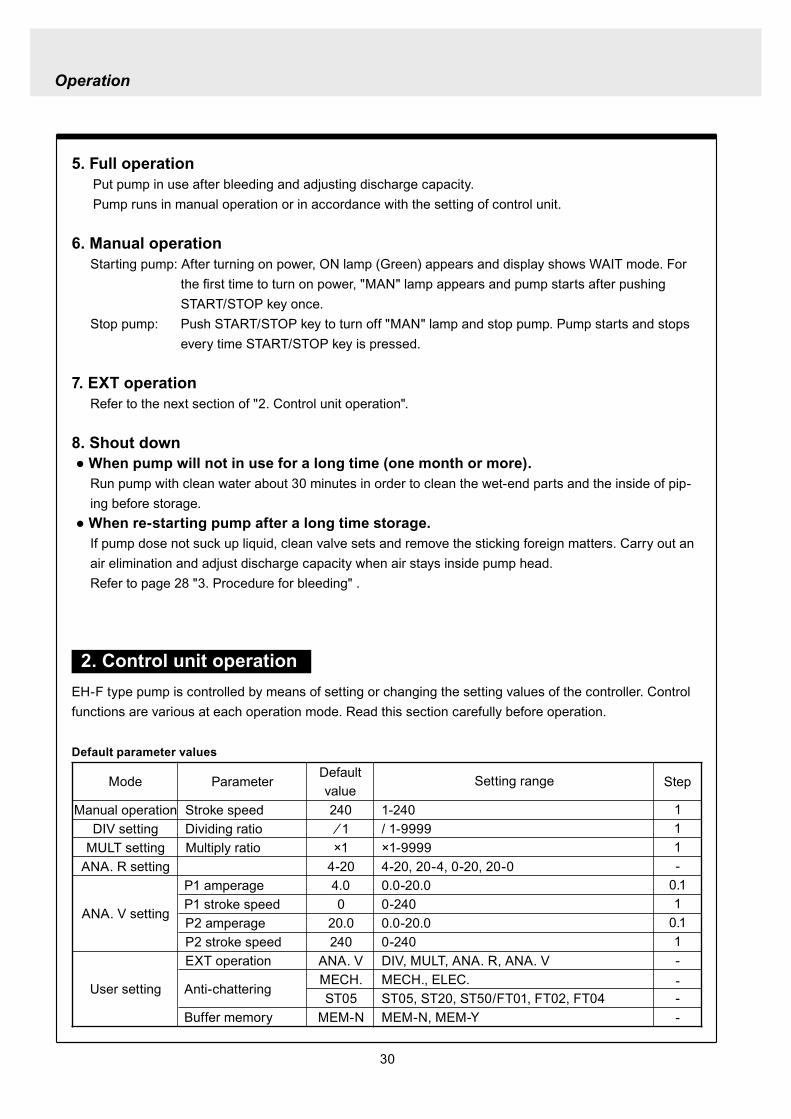
30
Mode ParameterDefault value
Setting range Step
Manual operation Stroke speed 240 1-240DIV setting Dividing ratio frasl 1 1-9999
MULT setting Multiply ratio times1 times1-9999ANA R setting 4-20 4-20 20-4 0-20 20-0
ANA V setting
P1 amperage 40 00-200P1 stroke speed 0 0-240P2 amperage 200 00-200P2 stroke speed 240 0-240
User setting
EXT operation ANA V DIV MULT ANA R ANA V
Anti-chatteringMECH MECH ELECST05 ST05 ST20 ST50FT01 FT02 FT04
Buffer memory MEM-N MEM-N MEM-Y
111-
011
011
2 Control unit operationEH-F type pump is controlled by means of setting or changing the setting values of the controller Control functions are various at each operation mode Read this section carefully before operation
Default parameter values
5 Full operationPut pump in use after bleeding and adjusting discharge capacityPump runs in manual operation or in accordance with the setting of control unit
6 Manual operationStarting pump After turning on power ON lamp (Green) appears and display shows WAIT mode For
the first time to turn on power MAN lamp appears and pump starts after pushing STARTSTOP key once
Stop pump Push STARTSTOP key to turn off MAN lamp and stop pump Pump starts and stops every time STARTSTOP key is pressed
7 EXT operationRefer to the next section of 2 Control unit operation
8 Shout down When pump will not in use for a long time (one month or more)
Run pump with clean water about 30 minutes in order to clean the wet-end parts and the inside of pip-ing before storage
When re-starting pump after a long time storage If pump dose not suck up liquid clean valve sets and remove the sticking foreign matters Carry out an air elimination and adjust discharge capacity when air stays inside pump head Refer to page 28 3 Procedure for bleeding
Operation
---
-
31
AN
A V
(Ana
log
var
iabl
e)
DIV
(Pul
se d
ivid
ing)
MU
LT(P
ulse
mul
tiply
)A
NA
R(A
nalo
g ri
gid)
SE
TS
ET
Use
r mod
e
EX
T m
ode
sele
ctio
n
EX
T
EX
TE
XT
EX
TE
XT
EX
T EX
T
EX
T
EX
T
EX
T
EX
T
EX
T
EX
T
EX
T
EX
T
EX
T
EX
T
EX
T
3 sec
onds
or m
ore
Wai
t mod
e
Set
ting
of fi
xatio
n pa
ttern
EX
T m
ode
Man
ual o
pera
tion
Set
ting
of s
troke
num
ber
AN
A R
(Ana
log
rigi
d)M
ULT
(Pul
se m
ultip
ly)
DIV
(Pul
se
div
idin
g)
AN
A V
(Ana
log
var
iabl
e)
anti-
chat
terin
gse
tting
dis
play
Setti
ng o
f div
idin
g ra
tioS
ettin
g of
cou
nt n
umbe
r
Curre
nt va
lue of
P1
Stro
ke nu
mbe
r of P
1
Curre
nt va
lue
of P
2
Stro
ke nu
mbe
r of P
2
EX
T O
pera
tion
Dis
play
EX
T se
tting
mod
e
Buf
fer m
emor
yse
tting
dis
play
Pow
er O
N
spm
MA
Nsp
m
spm
DIV
DIV
SE
TS
ET
MU
LT
MU
LTsp
mA
NA
V
spm
AN
AR
AN
AR
SE
Tm
AS
ET
mA
spm
AN
A
V
P1
mA
SE
T
spm
AN
A
V
P1
AN
AR
SE
Tm
A
AN
AR
SE
Tm
AS
ET
AN
A
V
P 2
SE
T
spm
AN
A
V
P 2
AN
AR
SE
Tm
A
AN
A
V
SE
TS
ET
SE
T
SE
T
SE
T
SE
T
SE
T
SE
T
SE
T
SE
T
SE
TS
ET
1 Overview Operating Scheme
Operation
1 means automatic transfer WAIT mode is selected when the power is switched on for the first time On and after the initial power activation pump restores the previous status right before the power is switched off
2 Regarding MANUAL mode pump starts operation by pushing STARTSTOP key at WAIT modePushing STARTSTOP key again the pump stops and returns to WAIT mode
3 Regarding EXT operation pushing EXT key at WAIT mode the pump moves to EXT mode and starts operationPushing STARTSTOP key stops the operation and returns the pump to WAIT mode
4 The change of each setting of EXT operation is accessible by pushing EXT key at EXT mode Pushing EXT key after the setting pump starts in EXT operation according to the changed setting
5 Pushing EXT key for 3 seconds at WAIT mode pump moves to USER mode At USER mode the EXT mode selection and the detailed setting such as the setting of buffer memory or so can be obtained
For details refer to each section of 2 Pump operation
2 Pump operation1 Operation of controller
Before turning on power confirm the specified power source on the nameplate
CAUTION
Connecting any other powers than the one shown on nameplate to pump is strictly prohibitedIt could lead to pump trouble or failure
Operation
32
1 Turning on powerDisplay shows WAIT mode when pump is turned on for the first time After the initial power activation the pump restores the previous mode right before the power was turned off last time If power is turned off at any setting modes WAIT mode appears at the next power activation
Stroke speed setting value is shown on display at WAIT mode ON lamp lights (Green)
EXT
EH-F ControllerSTARTSTOP
ON STOP
spm
33
2 Manual operation(1) Stroke speed can be adjusted by and
keys The figure changes quickly when either or key is depressed The picture below
shows the stroke speed is set to 160 spm
EXT
EH-F ControllerSTARTSTOP
ON STOP
spm
EXT
EH-F ControllerSTARTSTOP
ON STOP
MAN spm
EXT
EH-F ControllerSTARTSTOP
ON STOP
spm
(2) Push STARTSTOP key once to start the pump operation MAN indication appears and ON lamp blinks synchronously with each stroke
(3) MAN indication disappears and ON lamp stops blinking as STARTSTOP key is pushed again Pump enters WAIT mode
Operation
Operation
34
EXT
EH-F ControllerSTARTSTOP
ON STOP
ANA V
P1 SET mA
EXT
EH-F ControllerSTARTSTOP
ON STOP
P1 SET
ANA V spm
EXT
EH-F ControllerSTARTSTOP
ON STOP
spm
EXT
EH-F ControllerSTARTSTOP
ON STOP
ANA V spm
(4) Set the current value at P1 Figure increases or decreases as or key is pushed The pic-ture below shows 80 mA is set to point 1
EXT
EH-F ControllerSTARTSTOP
ON STOP
ANA V
P1 SET mA
(5) Pushing EXT key once spm appears on the display while mA disappears The picture below shows the number of strokes at P1
EXT
EH-F ControllerSTARTSTOP
ON STOP
P1 SET
ANA V spm
3 EXT operation (ANA V mode)(1) Push STARTSTOP key to move to WAIT mode
if pump is in another mode Go to next step if pump is in WAIT mode
(2) ANAV indication appears and pump enters an EXT mode as EXT key is pushed once Pump starts operation in accordance with current sig-nals and various settings ON lamp blinks at each pumping during operation Pump is con-trolled via the EXT mode which was select-ed at USER mode The initial setting of EXT mode is ANA V mode Select a preferable EXT mode in USER mode The picture below shows ANA V mode (The spm on the display changes according to input signals)
(3) Push EXT key once when pump is running in ANA V mode Display indicates the setting display of ANA V mode spm indication dis-appears and P1 SET and mA indications appear on the screen
(6) Set the number of strokes at P1 Figure increasesdecreases as key is pushed Picture below shows 10 spm is set for point 1
Operation
35
(7) Push EXT key to move to the setting display of the current value at P2 P1 and spm disap-pear and P2 and mA appears instead
EXT
EH-F ControllerSTARTSTOP
ON STOP
ANA V
P 2 SET mA
EXT
EH-F ControllerSTARTSTOP
ON STOP
ANA V
P 2 SET mA
EXT
EH-F ControllerSTARTSTOP
ON STOP
P 2 SET
ANA V spm
(11) Push EXT key to return to EXT mode Pump starts to run in ANA V mode on the setting of (4) through (10) ON lamp starts to blink at each pumping
EXT
EH-F ControllerSTARTSTOP
STOPON
ANA V spm
EXT
EH-F ControllerSTARTSTOP
ON STOP
P 2 SET
ANA V spm
EXT
EH-F ControllerSTARTSTOP
ON STOP
spm
(8) Set the current value of P2 by pushing and keys Picture below shows 180 mA is set to
point2
(9) Pushing EXT key once spm appears on the display while mA disappears The picture below shows the number of strokes at P2
(10) Set the number of strokes at P2 by pushing and keys Picture below shows 200
spm is set to point 2
(12) Pushing STARTSTOP key pump enters WAIT mode and pump stops ON lamp stops blink-ing and ANAV indication disappears
CAUTIONWhen the setting of the buffer memory is OFF keep the number of strokes in the dividing operation 240 spm or below The input signals to operate the pump over 240 spm can cause an unstable pump operationWhen the setting of the buffer memory is ON the pump operates for all the input pulse signalsPump keeps operating after all the signals are stopped in this case Be careful when setting of buffer memory
Operation
36
EXT
EH-F ControllerSTARTSTOP
ON STOP
DIV
SET
EXT
EH-F ControllerSTARTSTOP
ON STOP
DIV
SET
EXT
EH-F ControllerSTARTSTOP
STOPON
DIV spm
EXT
EH-F ControllerSTARTSTOP
ON STOP
spm
(2) Pushing EXT key DIV appears and pump starts operation in the ratio of input pulse sig-nals a pumping ON lamp blinks synchronous-ly at each pumping The initial setting of EXT selection is ANA V mode Change mode to DIV mode via USER mode Refer to P 40 for detail information
(3) Push EXT key while pump is operating in DIV mode Pump stop running and SET indication appears on the DIV setting display in stead of spm indication
(4) Enter a dividing ratioFigure increasesdecreases when key is pushed The picture below shows 10 is set
4 EXT operation (DIV mode)
(1) Push STARTSTOP key to move to WAIT mode if pump is in another mode Go to next step if pump is in WAIT mode
CAUTIONOn condition the setting of buffer memory is OFF do not input any pulse signals during the pumping motions for a input pulse signal in the multiply operation These input pulse signals are cancelledWhen the setting of buffer memory is ON pump operates for all the input pulse signals
Operation
37
EXT
EH-F ControllerSTARTSTOP
ON STOP
spm
EXT
EH-F ControllerSTARTSTOP
STOPON
DIV spm
EXT
EH-F ControllerSTARTSTOP
ON STOP
spm
EXT
EH-F ControllerSTARTSTOP
ON STOP
MULT
(5) Push EXT key to return to EXT operating mode Pump starts to run on the setting at item (4) ON lamp blinks synchronously at each pumping
(6) Pushing STARTSTOP key pump enters WAIT mode and pump stopsDIV indication disappears and ON lamp stops blinking
5 EXT operation (MULT mode)
(2) MULT indication appears and pump starts running in an EXT operation mode in the ratio of an input pulse signal pumpings as press-ing EXT key ON lamp blinks at each pump-ing Display shows the rest of the number of strokes In MULT mode the number of strokes is equal to the setting value in manual opera-tionThe initial setting of the EXT mode selection is ANA V mode which is the operation in pro-portion to current First select MULT mode via USER mode Refer to P 40 for detail informa-tion
(1) Push STARTSTOP key to move to WAIT mode if pump is in another mode Go to next step if pump is in WAIT mode
Operation
38
EXT
EH-F ControllerSTARTSTOP
ON STOP
spmEXT
EH-F ControllerSTARTSTOP
ON STOP
ANAR spm
EXT
EH-F ControllerSTARTSTOP
ON STOP
MULT
SET
EXT
EH-F ControllerSTARTSTOP
ON STOP
MULT
EXT
EH-F ControllerSTARTSTOP
ON STOP
spm
EXT
EH-F ControllerSTARTSTOP
ON STOP
MULT
SET
(5) Push EXT key to return to MULT mode(3) Pushing EXT key when pump is running in the multiply operation calls the setting display of MULT mode and SET indication appearsPump stops running and ON lamp stop blinking
(4) Enter the number of pumpings per input signalFigure increasesdecreases when key is pushed The picture below shows the pump-ing number is set to 1800 times per an input signal
6 EXT operation (ANA R mode)(1) Push STARTSTOP key to move to WAIT mode
if it is in another mode Go to next step if it is in WAIT mode
(6) Pushing STARTSTOP key recalls WAIT mode and pump stops spm indication appears in stead of MULT indication
(2) Pushing EXT key ANAR appears and pump starts running in the ratio of an input pulse sig-nal pumpings ON lamp blinks at each pump-ing The initial setting of the EXT mode selec-tion is ANA V mode which is the operation in proportion to current is selected First select ANA R mode in USER mode Refer to P 40 for more information
Operation
39
EXT
EH-F ControllerSTARTSTOP
ON STOP
ANAR
SET mA
EXT
EH-F ControllerSTARTSTOP
ON STOP
ANAR spm
EXT
EH-F ControllerSTARTSTOP
ON STOP
ANAR
SET mA
EXT
EH-F ControllerSTARTSTOP
ON STOP
spm
(4) Figure increasesdecreases when key is pushed The picture below is when it is set to 0-240 spm for 20-4 mA
(5) Push EXT key to return to EXT mode Pump starts to run on the setting at item (4) ON lamp blinks synchronously at each pumping
(6) When pushing STARTSTOP key pump enters WAIT mode and stops running ON lamp stops blinking and ANAR disappears
(3) Pushing EXT key when pump is running in the multiply operation calls the setting display of ANAR mode and SET and mA indications appear while spm disappears Pump stops running and ON lamp stops blinking
Operation
40
EXT
EH-F ControllerSTARTSTOP
ON STOP
ANA V
(5) Push EXT key to confirm the desired EXT mode Pump displays the EXT mode selection The picture below shows DIV appears to indi-cate DIV mode is selected
EXT
EH-F ControllerSTARTSTOP
ON STOP
DIV
EXT
EH-F ControllerSTARTSTOP
ON STOP
SET
EXT
EH-F ControllerSTARTSTOP
ON STOP
spm
EXT
EH-F ControllerSTARTSTOP
ON STOP
spm
EXT
EH-F ControllerSTARTSTOP
ON STOP
SET
7 USER settingThe setting of each function is changed in USER mode Have the pump entering WAIT mode in order to move to USER mode OUT (Output) is synchronous with spm and it can not be changed
7-1 EXT mode selection Any one of DIV (pulse dividing) MULT (pulse multiply) ANAR (analog rigid) or ANAV (analog vari-able) can be active in EXT mode The initial mode when shipped from factory is ANAV
(1) Push STARTSTOP key to move to WAIT mode if it is in another mode If it is in WAIT mode go to next step
(2) Press EXT key for more than 3 seconds to move to USER mode The picture below shows pump enters the EXT mode selection
(3) Pushing EXT key SET appears and display shows the mode currently set Picture below shows ANA V mode is selected
(4) Push or key to select a desired EXT mode The picture below shows DIV mode is selected
(6) Push STARTSTOP key to move to WAIT mode spm appears while DIV goes out
Operation
41
EXT
EH-F ControllerSTARTSTOP
ON STOP
spm
EXT
EH-F ControllerSTARTSTOP
ON STOP
ANA V
EXT
EH-F ControllerSTARTSTOP
ON STOP
SET
(3) Push key once
EXT
EH-F ControllerSTARTSTOP
ON STOP
(4) Push key again to move to the anti-chatter-ing setting display
EXT
EH-F ControllerSTARTSTOP
ON STOP
(5) Pushing EXT key display shows the mode cur-rently set and SET appears on it The picture below shows when MECH is selected
EXT
EH-F ControllerSTARTSTOP
ON STOP
SET
7-2 Setting of anti-chattering Anti-chattering function is settable against the incoming pulses during the DIV or MULT operation For the long chattering of mechanical contact such as relay set a large figure via MECH For the high speed (high frequency) chattering of the semi-conductor type contact such as transistor set a small figure via ELEC ST05 of MECH is initial setting
(6) Select MECH by or key for a mechani-cal contact And select ELEC for a semi-conductor contact The picture below shows ELEC is selected
(1) Push STARTSTOP key to move to WAIT mode if it is in another mode If it is in WAIT mode go to next step
(2) Press EXT key for more than 3 seconds to move to USER mode The picture below shows pump enters the EXT mode selection
Operation
42
EXT
EH-F ControllerSTARTSTOP
ON STOP
SET
(7) Push EXT key to display the current set state The picture below shows FT01 is selected
EXT
EH-F ControllerSTARTSTOP
ON STOP
SET EXT
EH-F ControllerSTARTSTOP
ON STOP
EXT
EH-F ControllerSTARTSTOP
ON STOP
spm
7-3 Setting of buffer memoryIn case pump operation can not catch up with the input pulse signals in DIV or MULT operation exces-sive pulse signals can be put in memory up to 65535 pulses However the excessive pulses can not be restored if once power is off or mode is changed
EXT
EH-F ControllerSTARTSTOP
ON STOP
spm
(2) Press EXT key for 3 seconds or more to move to USER mode The picture below shows the EXT mode selection display
EXT
EH-F ControllerSTARTSTOP
ON STOP
ANA V
(8) Set a large figure for the long chattering by or key and set a small figure for high speed (high frequency) chattering The picture below shows FT04 is selected
(9) Push EXT key to return to the anti-chattering setting display SET indication disappears
(10) Push STARTSTOP key to return to wait mode spm indication appears
(1) Push STARTSTOP key to move to WAIT mode if it is in another mode If it is in WAIT mode go to next
Operation
43
(3) Push key once
EXT
EH-F ControllerSTARTSTOP
ON STOP
(7) Push or key in order to set buffer memo-ry to ON or OFF Select MEM-Y to set it ON Select MEM-N for OFF setting The picture below shows when ON is set
EXT
EH-F ControllerSTARTSTOP
ON STOP
SET
(4) Push key once again
EXT
EH-F ControllerSTARTSTOP
ON STOP
(8) Push EXT key to return to the buffer memory setting display SET indication disappears
EXT
EH-F ControllerSTARTSTOP
ON STOP
(9) Push STARTSTOP key to return to WAIT mode spm indication appears
EXT
EH-F ControllerSTARTSTOP
ON STOP
spm
(5) Push key once again and the buffer memory setting display is shown
EXT
EH-F ControllerSTARTSTOP
ON STOP
(6) Push EXT key in order to display the current set state SET indication appears The picture below shows the buffer memory is set to OFF
EXT
EH-F ControllerSTARTSTOP
ON STOP
SET
Operation
44
8 Bleeding amp self-primingAt WAIT mode Manual operating mode and EXT operating mode pump operates at max speed tak-ing priority over any functions when both and keys are pushed at once Pump runs at max speed only when both keys are depressed Pump state returns to the previous mode once either or key is released Pressing and keys for 10 seconds keeps pump running at maximum speed In this state this fixation is released when pushing either or key once and pump returns to the previous mode
(1) When pump is running in ANAV mode
EXT
EH-F ControllerSTARTSTOP
ON STOP
ANA V spm
(2) Pump start to run at full speed when and keys are pressed at once Display shows
PRIME If either or key is released pump returns to the previous mode In this case pump returns to ANAV mode
EXT
EH-F ControllerSTARTSTOP
ON STOP
ANA V
(3) Pressing both and keys simultaneously for 10 seconds or more pump continues to run at full speed even if both keys are released In this case indication appearsPush either or key to release this state indication disappears and pump returns to the previous mode In this case pump returns to ANAV mode
EXT
EH-F ControllerSTARTSTOP
ON STOP
ANA V
Operation
45
10 Error display and release(1) In case Input signals fall to 4 mA or below while
4-20 or 20-4 is set to ANA R mode pump stops with DISCN blinking and Err on dis-play
(2) This error state can be released by push-ing STARTSTOP key and pumps enters wait mode In this case check the wiring and input signals
EXT
EH-F ControllerSTARTSTOP
ON STOP
ANAR
Err
spm
EXT
EH-F ControllerSTARTSTOP
ON STOP
spm
9 Key lockKey lock function is to prevent pump from being operated by some other person than user If STARTSTOP key is pressed for five seconds or more when pump is running or stops all key operations become ineffective with LOCK indication on display This function can be released by pressing STARTSTOP key for 5 seconds while LOCK lights
EXT
EH-F ControllerSTARTSTOP
ON STOP
MAN spm
LOCK
46
Do not conduct a maintenance work with the wet hands It can cause an electric shock
Before dismantling pump be sure to turn off power and check the pump is not electrified Do not
start a dismantlement work after stopping the pump by pushing the STARTSTOP key only Put up
the sign of ldquoMaintenance work is in progressrdquo in order to prevent a pump switch from turning on
unintentionally during the work Release the pressure of discharge piping and drain the liquid from
the wet end parts And then clean the inside of pump head
Wear protective clothing such as a protective mask globes goggles and chemical-proof wear
according to the handled chemical liquid during the work
WARNING
5 Maintenance
1 Trouble shootingTrouble Cause Troubleshooting
Pump dose not start Faulty wiring or disconnection in wiring Voltage is too low Failure in the electronic circuit of control unit
Pump dose not suck liquidDischarge amount is low
Air suction from suction piping Valve gasket is not installed Valve set assembling direction is wrong Pump is air-locked Pump stroke length is too short Suction-sidedischarge-side valve is clogged with
foreign matter Adhesion of valve onto valve seat
Discharge amount fluctuates
Liquid leaks
Key operation is ineffective Key is locked Release key lock
Pump doesnt run
Pump is in waiting mode Signals are not coming for EXT operation Pump is in EXT setting mode Pump is suspended with STOP
Move to operation mode Check wiring and correct the wrong part Move to EXT operating mode Release STOP function
Abnormal noise
Suction-sidedischarge-side valve is clogged with foreign matters
The sound absorption gasket is worn out Bearing is worn out Spring is damaged
Piping vibrates due to pulsation Bearing is worn out Spring is damaged
Install a accumulator or an air chamber The end of pump life span The end of pump life span
Suction-sidedischarge-side valve is clogged with foreign matters
Air is trapped in pump Overfeeding Diaphragm is damaged
Fittings are not tightly closed Pump head is not tightened Diaphragm is damaged O ring and valve gasket are not installed O ring is damaged
Correct wiring Inspect power source and provide measurement Replace the whole unit
Arrange piping again Install valve gasket Reassemble valve set Carry out air elimination Drive pump with 100 stroke length to prime liquid Then
reset stroke length Disassemble inspect and clean Disassemble inspect and clean
Tighten fittings Tighten pump head Replace diaphragm Install O ring and valve gasket Replace O ring
Disassemble inspect and clean
Carry out air elimination Install a check valve or a back pressure valve Replace diaphragm
Disassemble inspect and clean
The end of pump life span The end of pump life span The end of pump life span
Abnormal vibration
Input pulse can not be read Signals are not coming Anti-chattering setting is not proper
Check wiring and correct the wrong part Change the setting properly
Analog signal input can not be read
Wrong wiring Signals are over acceptable loaded resistance
Check wiring and correct wrong part The load resistance is 200Ω Use some devise which can
accept the load resistance
47
CAUTION Check periodically whether the bolts fixing pump head are tightened Tighten them as needed
The bolts fixing pump head may loosen in operation Tightening torque 255Nbullm
Maintenance
3
bull Tighten joint where leakage has occurredbull The excessive air bubbles in the discharged liquid mean air suc-
tion has been caused in system Examine the piping and tighten joint on where leaks
Is there liquid leakage or air suction at any joints on pump or piping
2 Maintenance and inspection
1 Daily inspectionPay attention to the following points during pump operation Stop pump immediately upon detecting abnormality and take measures according to the item Troubleshooting When wear parts come to the life time replace them by new ones
No
1
2
Check Point Description
Does pump lift liquid normally
bull Is liquid normally fedbull Is suction pressuredischarge pressure at normal levelbull Has liquid undergone quality change crystallization or solidifica-
tion
Abnormal noise or vibrationbull Abnormal noise or vibration may happen from the abnormal func-
tioning of pump
EXT setting can not be stored
After EXT setting STARTSTOP key is pushed for EXT by mistake
Push EXT key to operate pump in EXT mode
ldquoPRIME is kept indicated and other operations are inac-cessible
Self-priming function is active Push either or key to release the function
Analog signal input can not be read and DISCN indication appears
Wrong wiring or disconnection Check wiring and correct the wrong part Refer to page 45
for how to release an error indication
Trouble Cause Troubleshooting
48
Maintenance
2 Wear partsWear parts should be replaced in proper period for a long period of pump operation It is recommended that follow-ing parts are always ready for the replacementVC V6 PC P6 types
Parts Qty Life span
Pum
p he
ad
Valve set
EH-F35 EH-F45 EH-F55middot70
2sets
8000hours
Diaphragm 1
Refer to exploded view
Bac
k pr
essu
re v
alve
1
2
Che
ck v
alve
7 6 1
8 11 1
Diaphragm seat 1
O ring
Poppet check valve (With check gasket)
Check valve spring Spacer
Diaphragm
O ring
Note Durability of wear parts depend on the pumped liquid temperature and pressure Time to be replaced mentioned as above is the estimation obtained by continuous pump-ing of clean water at ambient temperature
8000hours
4000hours
49
3 Dismantlement and assembly
Getting wet with or coming in contact with chemicals and toxic liquid is harmful Wear protective clothing such as a protective mask globes goggles and chemical-proof wear during the work
Risk of electrical shock Be sure to turn off power and confirm that pump and devices are not electrified before the work
Release the pressure inside pump and a discharge hose by opening an air bleed valve on piping prior to loosening the piping connections or the dismantlement of pump Dismantlement with the pressure inside pump could lead to liquid spillage
Be careful not to touch residual liquid when dismantling pump Some liquids are harmful for skin or component parts Wipe off liquid when the hand or the component parts come in contact with liquid
WARNING
CAUT ION
Hose
Hose stopperFitting spacer
O ring
Fitting nut
Fitting
Pumphead
Remove the fittingwith a spanner
1 Valve set replacement Dismantlement1 Loosen a fitting nut and remove the hose con-
nected to pump head Pay attention to the liquid dripping
2 Loosen a fitting with a spanner to remove it Then detach the valve set from pump head
Maintenance
50
AssemblyAssembly procedure is in reverse order to disas-sembly Pay attention to the following when assembling valve set DispositionInsertion direction of valve set The wrong dispositioninsertion direction of valve
set component can lead to leakage and less dis-charge amount
O ring is fitted properly1 Discharge side valve set mounting
Put valve set in pump head and screw a fitting into a pump head by hand and then re-tighten it by 14 turns with a spanner
2 Suction side valve set mountingPut valve set in connection port and screw the fitting into pump head by hand and then re-tighten it by 14 turns with spanner
Note Pay attention to the mounting direction of the spacer fitted to EH-F45(VC V6 PC)Make sure the cut portion on the spacer of suction side should be downward the one of discharge side should be upward
Suction side
Discharge side
O ringValve gasket
Valve gasket
Valve gasket
Valve guideValveValve seatSpacer
O ring
Valve gasketValve guideValveValve seat
Spacer
1714
11
1312
11
1312
17
17
14
14
14
11
31
1312
31
17
14
11
1312
12
13
11
14
EH-F35
EH-F45
EH-F5570
Suct
ion
side
Dis
char
ge s
ide
For b
oth
suct
ion
and
disc
harg
e si
deFo
r bot
h su
ctio
nan
d di
scha
rge
side
VC V6 PC P6 Type
Maintenance
51
Pay attention not to lose diaphragm spacer and to apply the correct number of diaphragm spacers 0 to several pieces of diaphragm spacers are put between retainer and plunger to adjust the position of diaphragm The number of spacers mounted depends on the pump model There are the models which do not have spacers
Maintenance
2 Diaphragm replacement Dismantlement1 Set stroke length to 0 by adjusting stroke length
adjustment knob
2 Remove the pump head from the pump body by loos-ening hex socket cap bolts
3 Rotate a diaphragm anti-clockwise to remove it from a plunger pin The diaphragm is screwed into the plunger pin
AssemblyAssembly is done in reverse order to disassembly Follow the steps below1 Make sure the stroke length of pump is set to 0
prior to an assembly Operate pump to set the stroke length to 0 and
stop it Then turn off power
2 Fit a rear diaphragm seat a retainer and a diaphragm spacer into new diaphragm via the threaded pin and screw the diaphragm into the plunger pin
Fit the concave side of retainer into the convex side of diaphragm Pay attention the retainer dose not come off
3 Set the stroke length to 100 Operate pump to set the stroke length to 100
and stop it Then turn off power4 Install a pump head to a pump body by tightening
the hex sock cap bolts equally Tightening torque is 255Nbullm
52
4 Accessories1 Connection port bore bull Check valve bull Back pressure valve
Note1 Check valves and back pressure valves are options2 Regarding the connection of the discharge side of back pressure valve
NPT38 and NPT12 taper pipe thread is used for BV-N-CR
Pump type Connection port bore Check valve Back pressure valve
EH-F35VC empty38timesempty12 hose CA-3VCH-C6 ndash
empty38timesempty12 hose CA-3VEH-C6 ndashempty38timesempty12 hose CA-3VH-C6 ndashempty38timesempty12 hose CA-3VCH-C6 ndashempty38timesempty12 hose CA-3VEH-C6 ndashempty38timesempty12 hose CA-3VH-C6 ndash
V6
empty38timesempty12 hose ndash BV-3NV-C6Rempty38timesempty12 hose ndash BV-3NE-C6Rempty38timesempty12 hose ndash BV-3NPV-C6Rempty58timesempty34 hose ndash BV-3NV-C7Rempty58timesempty34 hose ndash BV-3NE-C7Rempty58timesempty34 hose ndash BV-3NPV-C7R
PC
EH-F45VCV6PC
EH-F55VCV6PC
EH-F70VCV6PC
Maintenance
53
Maintenance
5 Exploded view
1 General view The extent of dismantlement is within the following exploded view
Diaphragm spacer
Retainer
(Back up retainer)55 bull 70 types
Pump body
Valve set
Valve set
Pump head
Diaphragm
Rear diaphragm sheet
54
2 Pump head (Hose connection type)
EH-F45 type EH-F35 type
4
28
2930
3
1114
131211
131217
1897
1
17
111312111312
3
3029
28
4
1920
1920 21
17
111312
31
3
3029
28
4
131217
189
7
11
3114
14
4
282930
3
1
21
1515
EH-F55 type
4
28
2930
3
11
131217
18
9
7
10
1
1920 21
17
111312
3
30
29
28
4
EH-F70 type
4
28
2930
3
14
11131217
18
9
7
10
1
1920 21 17
111312
3
30
29
28
4
15 15
14
1414
14
14 14
Note1 The back up retainer of No10 is only for EH-F55 bull 70 typesNote2 The figure inside ( ) in the above table is for EH-F45 bull 55 bull 70 typesNote3 The number of the diaphragm spacers (No18) is not constant None or a few spacers is inserted at
each diaphragmNote4 The figure inside ( ) in the above table is for EH-F70Note5 EH-F35 bull 55 bull 70 (VC V6 PC ) types require 2 valve gaskets and EH-F45 (VC V6 PC) types
require 4 of themNote6 The spacer on No31 is for EH-F45 type only
No Name Qty1 Pump head 13 Fitting 24 Fitting nut 27 Diaphragm 19 Retainer 110 Back up retainer 1 Note111 Valve guide 4 (2) Note212 Valve seat13 Valve14 Valve gasket
No Name Qty
17 O ring 218 Diaphragm spacer 1 Note319 Hex socket head bolt 6 (8) Note420 Spring washer21 Plain washer28 Hose stopper 229 Fitting spacer 230 O ring 231 Spacer 2 Note6
15 Rear diaphragm seat 1
2 (4) Note54 (2) Note24 (2) Note2
6 (8) Note46 (8) Note4
Maintenance
55
Maintenance
3 Pump head (Flange connection type) EH-F55 type
30
3
11
131217
18
9
7
10
1
1920 21
17
11
1312
3
30
EH-F70 type
15
EH-F45 type EH-F35 type
30
3
11131211
131217
1897
1
17
11131211
1312
3
30
1920
1920 21
17
111312
31
3
131217
189
7
11
31
30
3
1
30
21
1515
30
3
11131217
18
9
7
10
1
1920 21 17
11
1312
3
30
15
32
33
33
32
4
32
433
43332
32
334
43332
32
33
32
334
44
1414
14 14 14
1414
14
14 14
NoNo Name Qty1 Pump head 13 Fitting 24 Fitting nut 27 Diaphragm 19 Retainer 110 Back up retainer 1 Note111 Valve guide 4(2)Note212 Valve seat 4(2)Note213 Valve 4(2)Note214 Valve gasket 2(4)Note5
Name Qty
17 O ring 218 Diaphragm spacer 1 Note319 Hex socket cap bolt 6(8)Note420 Spring washer 6(8)Note421 Plain washer 6(8)Note430 O ring 2
33 Union 2
31 Spacer 2 Note6
15 Rear diaphragm seat 1
32 Flange 2
Note1 The back up retainer of No10 is only for EH-F55 bull 70 typesNote2 The figure inside ( ) in the above table is for EH-F45 bull 55 bull 70 typesNote3 The number of the diaphragm spacers (No18) is not constant None or a few spacers is inserted at
each diaphragmNote4 The figure inside ( ) in the above table is for EH-F70Note5 EH-F35 bull 55 bull 70 (VC V6 ) types require 2 valve gaskets and EH-F45 (VC V6) types require 4 of
themNote6 The spacer on No31 is for EH-F45 type only
56
4 Pump head (Flange connection horizontal suction port type) EH-F55 type
30
3
11
131217
18
9
7
10
1
1920 21
17
111312
3
30
EH-F70 Type
15
EH-F45 Type EH-F35 type
30
3
11131211
131217
1897
1
17
111312111312
3
30
1920
1920 21
17
11131231
3
131217
189
7
11
31
30
3
1
30
21
1515
30
3
11131217
18
9
7
10
1
1920 21 17
111312
3
30
15
32
33
32
433
43334
32
32
334
43334
32
33
44
34
32
334
34
32
334
32
35 353535
1414
14 14 14
1414
14
14 14
No Name Qty1 Pump head 13 Fitting 24 Fitting nut 27 Diaphragm 19 Retainer 110 Back up retainer 1 Note111 Valve guide 4 (2) Note212 Valve seat13 Valve
15 Rear diaphragm sheet 114 Valve gasket
No Name Qty
18 Diaphragm spacer 1 Note319 Hex socket cap bolt20 Spring washer21 Plain washer
31 Spacer 2 Note6
35 Pipe 1
32 Flange 2
34 Elbow 133 Union 2
17 O ring 2
30 O ring 2
4 (2) Note24 (2) Note22 (4) Note5
6 (8) Note4
4 (2) Note24 (2) Note2
Maintenance
Note1 The back up retainer of No10 is only for EH-F55 bull 70 typesNote2 The figure inside ( ) in the above table is for EH-F45 bull 55 bull 70 typesNote3 The number of the diaphragm spacers (No18) is not constant None or a few spacers is inserted at
each diaphragmNote4 The figure inside ( ) in the above table is for EH-F70Note5 EH-F35 bull 55 bull 70 (VC V6) types require 2 valve gaskets and EH-F45 (VC V6) types require 4 of
themNote6 The spacer on No31 is for EH-F45 type only
57
5 Check valve CA-3 type
1 2 3 4 5 6 7 8 11 9 10
16
14
13
15
12
3
15
17
16
1110
98
7
1
54
2
6
14
13
6 Back pressure valve BV-3N-R type
No No Name Qty10 Stopper 111 Diaphragm 112 Lower case 113 Fitting spacer Hose port 114 Hose stopper Ferrule 115 O ring 216 Nut 217 Fitting 1
Name Qty1 Upper case 12 Hexhead bolt (with PW SW) 43 Hex nut 44 Adjusting bolt 15 Hexnut 16 Plain washer 1
8 Spring 19 Retainer plate 1
7 Spring seat 1
NoNo Name Qty1 Fitting nut 12 Hose stopper 13 Fitting spacer 14 O ring 15 Valve case 16 Gasket 1
Name Qty7 Poppet valve 18 Spring 19 O ring 110 Valve fitting 111 Spacer 1
Maintenance
58
Maintenance
1 Outer dimension (Hose connection type) EH-F35 type
TUBING(38rdquotimes12rdquo)
38rdquotimes12rdquo
EH-F45 type
38rdquotimes12rdquo
38rdquotimes12rdquo
59
EH-F55 type
58rdquotimes34rdquo
58rdquotimes34rdquo
EH-F70 type
Maintenance
38rdquotimes12rdquo
38rdquotimes12rdquo
60
Maintenance
2 Outer dimension (Flange connection type) EH-F35 type
EH-F45 type
61
EH-F55 type
EH-F70 type
Maintenance
62
Maintenance
3 Outer dimension (Flange connection horizontal suction port type) EH-F35 type
EH-F45 type
63
EH-F55 type
EH-F70Type
Maintenance
httpwwwiwakipumpsjp
Read this manual before use of product
IWAKIElectromagnetic Metering Pump
EH-F series (North America)
Instruction ManualT596 0706
GermanyItalyDenmarkSwedenFinlandNorwayFranceUKSwitzerlandAustriaHollandSpainBelgiumUSA
TEL (49)2154 9254 0TEL (39)02 990 3931TEL (45)48 24 2345TEL (46)8 511 72900TEL (358)9 2742714TEL (47)66 81 16 60TEL (33)1 69 63 33 70TEL (44)1743 231363TEL (41)26 674 9300TEL (43)2236 33469TEL (31)297 241121TEL (34)943 630030TEL (32)1367 0200TEL (1)508 429 1440
AustraliaSingaporeIndonesiaMalaysiaTaiwanThailandHong KongChinaChinaChinaChinaPhilippinesKoreaVietnam
TEL (61)2 9899 2411TEL (65)6316 2028TEL (62)21 690 6606TEL (60)3 7803 8807TEL (886)2 8227 6900TEL (66)2 322 2471TEL (852)2 607 1168TEL (86)750 380 9018TEL (86)20 8435 0603TEL (86)10 6442 7713TEL (86)21 6272 7502TEL (63)2 888 0245TEL (82)2 3474 0523TEL (84)613 933456
IWAKI EUROPE GmbH IWAKI Italia SRL IWAKI Nordic AS IWAKI Sverige AB IWAKI Suomi Oy IWAKI Norge AS IWAKI France SA IWAKI PUMPS (UK) LTD IWAKI (Schweiz) AG IWAKI (Austria) GmbH IWAKI Holland BV IWAKI Iberica Pumps SA IWAKI Belgium nv IWAKI America Incorporated
FAX 2154 1028FAX 02 990 42888FAX 48 24 2346FAX 8 511 72922FAX 9 2742715FAX 66 81 16 61FAX 1 64 49 92 73FAX 1743 366507FAX 26 674 9302FAX 2236 33469FAX 297 273902FAX 943 628799FAX 1367 2030FAX 508 429 1386
IWAKI Pumps Australia Pty Ltd IWAKI Singapore Pte Ltd IWAKI Singapore (Indonesia Branch) IWAKIm Sdn Bhd IWAKI Pumps Taiwan Co Ltd IWAKI (Thailand) CoLtd IWAKI Pumps Co Ltd IWAKI Pumps (Guandong) Co Ltd GFTZ IWAKI Engineering amp Trading (Guangzhou) IWAKI Pumps Co Ltd (Beijing) IWAKI Pumps (Shanghai) Co Ltd IWAKI Chemical Pumps Philippines Inc IWAKI Korea CoLtd IWAKI Pumps Vietnam Joint Venture CoLtd
FAX 2 9899 2421FAX 6316 3221FAX 21 690 6612FAX 3 7803 4800FAX 2 8227 6818FAX 2 322 2477FAX 2 607 1000FAX 750 380 9078FAX 20 8435 9181FAX 10 6442 7712FAX 21 6272 6929FAX 2 843 3096FAX 2 3474 0221FAX 613 933399
( )Country codes
IWAKI COLTD 6-6 Kanda-Sudacho 2-chome Chiyoda-ku Tokyo 101-8558 JapanTEL(81)3 3254 2935 FAX3 3252 8892(httpwwwiwakipumpsjp)
This is patent pending product
- 107
- 47
- 48
- 49
- 50
- 3
- 4
- 64
- 102
- 101
- 78
- 79
- 91
- 81
- 100
- 99
- 84
- 86
- 85
- 87
- 22
- 23
- 73
- 72
- 26
- 98
- 28
- 27
- 31
- 32
- 29
- 30
- 95
- 34
- 33
- 96
- 35
- 36
- 37
- 38
- 40
- 39
- 41
- 42
- 59
- 58
- 45
- 7
- 6
- 46
- 5
- 8
- 9
- 74
- 75
- 10
- 11
- 61
- 60
- 15
- 14
- 62
- 63
- 16
- 17
- 18
- 19
- 92
- 94
- 93
- 103

31
AN
A V
(Ana
log
var
iabl
e)
DIV
(Pul
se d
ivid
ing)
MU
LT(P
ulse
mul
tiply
)A
NA
R(A
nalo
g ri
gid)
SE
TS
ET
Use
r mod
e
EX
T m
ode
sele
ctio
n
EX
T
EX
TE
XT
EX
TE
XT
EX
T EX
T
EX
T
EX
T
EX
T
EX
T
EX
T
EX
T
EX
T
EX
T
EX
T
EX
T
EX
T
3 sec
onds
or m
ore
Wai
t mod
e
Set
ting
of fi
xatio
n pa
ttern
EX
T m
ode
Man
ual o
pera
tion
Set
ting
of s
troke
num
ber
AN
A R
(Ana
log
rigi
d)M
ULT
(Pul
se m
ultip
ly)
DIV
(Pul
se
div
idin
g)
AN
A V
(Ana
log
var
iabl
e)
anti-
chat
terin
gse
tting
dis
play
Setti
ng o
f div
idin
g ra
tioS
ettin
g of
cou
nt n
umbe
r
Curre
nt va
lue of
P1
Stro
ke nu
mbe
r of P
1
Curre
nt va
lue
of P
2
Stro
ke nu
mbe
r of P
2
EX
T O
pera
tion
Dis
play
EX
T se
tting
mod
e
Buf
fer m
emor
yse
tting
dis
play
Pow
er O
N
spm
MA
Nsp
m
spm
DIV
DIV
SE
TS
ET
MU
LT
MU
LTsp
mA
NA
V
spm
AN
AR
AN
AR
SE
Tm
AS
ET
mA
spm
AN
A
V
P1
mA
SE
T
spm
AN
A
V
P1
AN
AR
SE
Tm
A
AN
AR
SE
Tm
AS
ET
AN
A
V
P 2
SE
T
spm
AN
A
V
P 2
AN
AR
SE
Tm
A
AN
A
V
SE
TS
ET
SE
T
SE
T
SE
T
SE
T
SE
T
SE
T
SE
T
SE
T
SE
TS
ET
1 Overview Operating Scheme
Operation
1 means automatic transfer WAIT mode is selected when the power is switched on for the first time On and after the initial power activation pump restores the previous status right before the power is switched off
2 Regarding MANUAL mode pump starts operation by pushing STARTSTOP key at WAIT modePushing STARTSTOP key again the pump stops and returns to WAIT mode
3 Regarding EXT operation pushing EXT key at WAIT mode the pump moves to EXT mode and starts operationPushing STARTSTOP key stops the operation and returns the pump to WAIT mode
4 The change of each setting of EXT operation is accessible by pushing EXT key at EXT mode Pushing EXT key after the setting pump starts in EXT operation according to the changed setting
5 Pushing EXT key for 3 seconds at WAIT mode pump moves to USER mode At USER mode the EXT mode selection and the detailed setting such as the setting of buffer memory or so can be obtained
For details refer to each section of 2 Pump operation
2 Pump operation1 Operation of controller
Before turning on power confirm the specified power source on the nameplate
CAUTION
Connecting any other powers than the one shown on nameplate to pump is strictly prohibitedIt could lead to pump trouble or failure
Operation
32
1 Turning on powerDisplay shows WAIT mode when pump is turned on for the first time After the initial power activation the pump restores the previous mode right before the power was turned off last time If power is turned off at any setting modes WAIT mode appears at the next power activation
Stroke speed setting value is shown on display at WAIT mode ON lamp lights (Green)
EXT
EH-F ControllerSTARTSTOP
ON STOP
spm
33
2 Manual operation(1) Stroke speed can be adjusted by and
keys The figure changes quickly when either or key is depressed The picture below
shows the stroke speed is set to 160 spm
EXT
EH-F ControllerSTARTSTOP
ON STOP
spm
EXT
EH-F ControllerSTARTSTOP
ON STOP
MAN spm
EXT
EH-F ControllerSTARTSTOP
ON STOP
spm
(2) Push STARTSTOP key once to start the pump operation MAN indication appears and ON lamp blinks synchronously with each stroke
(3) MAN indication disappears and ON lamp stops blinking as STARTSTOP key is pushed again Pump enters WAIT mode
Operation
Operation
34
EXT
EH-F ControllerSTARTSTOP
ON STOP
ANA V
P1 SET mA
EXT
EH-F ControllerSTARTSTOP
ON STOP
P1 SET
ANA V spm
EXT
EH-F ControllerSTARTSTOP
ON STOP
spm
EXT
EH-F ControllerSTARTSTOP
ON STOP
ANA V spm
(4) Set the current value at P1 Figure increases or decreases as or key is pushed The pic-ture below shows 80 mA is set to point 1
EXT
EH-F ControllerSTARTSTOP
ON STOP
ANA V
P1 SET mA
(5) Pushing EXT key once spm appears on the display while mA disappears The picture below shows the number of strokes at P1
EXT
EH-F ControllerSTARTSTOP
ON STOP
P1 SET
ANA V spm
3 EXT operation (ANA V mode)(1) Push STARTSTOP key to move to WAIT mode
if pump is in another mode Go to next step if pump is in WAIT mode
(2) ANAV indication appears and pump enters an EXT mode as EXT key is pushed once Pump starts operation in accordance with current sig-nals and various settings ON lamp blinks at each pumping during operation Pump is con-trolled via the EXT mode which was select-ed at USER mode The initial setting of EXT mode is ANA V mode Select a preferable EXT mode in USER mode The picture below shows ANA V mode (The spm on the display changes according to input signals)
(3) Push EXT key once when pump is running in ANA V mode Display indicates the setting display of ANA V mode spm indication dis-appears and P1 SET and mA indications appear on the screen
(6) Set the number of strokes at P1 Figure increasesdecreases as key is pushed Picture below shows 10 spm is set for point 1
Operation
35
(7) Push EXT key to move to the setting display of the current value at P2 P1 and spm disap-pear and P2 and mA appears instead
EXT
EH-F ControllerSTARTSTOP
ON STOP
ANA V
P 2 SET mA
EXT
EH-F ControllerSTARTSTOP
ON STOP
ANA V
P 2 SET mA
EXT
EH-F ControllerSTARTSTOP
ON STOP
P 2 SET
ANA V spm
(11) Push EXT key to return to EXT mode Pump starts to run in ANA V mode on the setting of (4) through (10) ON lamp starts to blink at each pumping
EXT
EH-F ControllerSTARTSTOP
STOPON
ANA V spm
EXT
EH-F ControllerSTARTSTOP
ON STOP
P 2 SET
ANA V spm
EXT
EH-F ControllerSTARTSTOP
ON STOP
spm
(8) Set the current value of P2 by pushing and keys Picture below shows 180 mA is set to
point2
(9) Pushing EXT key once spm appears on the display while mA disappears The picture below shows the number of strokes at P2
(10) Set the number of strokes at P2 by pushing and keys Picture below shows 200
spm is set to point 2
(12) Pushing STARTSTOP key pump enters WAIT mode and pump stops ON lamp stops blink-ing and ANAV indication disappears
CAUTIONWhen the setting of the buffer memory is OFF keep the number of strokes in the dividing operation 240 spm or below The input signals to operate the pump over 240 spm can cause an unstable pump operationWhen the setting of the buffer memory is ON the pump operates for all the input pulse signalsPump keeps operating after all the signals are stopped in this case Be careful when setting of buffer memory
Operation
36
EXT
EH-F ControllerSTARTSTOP
ON STOP
DIV
SET
EXT
EH-F ControllerSTARTSTOP
ON STOP
DIV
SET
EXT
EH-F ControllerSTARTSTOP
STOPON
DIV spm
EXT
EH-F ControllerSTARTSTOP
ON STOP
spm
(2) Pushing EXT key DIV appears and pump starts operation in the ratio of input pulse sig-nals a pumping ON lamp blinks synchronous-ly at each pumping The initial setting of EXT selection is ANA V mode Change mode to DIV mode via USER mode Refer to P 40 for detail information
(3) Push EXT key while pump is operating in DIV mode Pump stop running and SET indication appears on the DIV setting display in stead of spm indication
(4) Enter a dividing ratioFigure increasesdecreases when key is pushed The picture below shows 10 is set
4 EXT operation (DIV mode)
(1) Push STARTSTOP key to move to WAIT mode if pump is in another mode Go to next step if pump is in WAIT mode
CAUTIONOn condition the setting of buffer memory is OFF do not input any pulse signals during the pumping motions for a input pulse signal in the multiply operation These input pulse signals are cancelledWhen the setting of buffer memory is ON pump operates for all the input pulse signals
Operation
37
EXT
EH-F ControllerSTARTSTOP
ON STOP
spm
EXT
EH-F ControllerSTARTSTOP
STOPON
DIV spm
EXT
EH-F ControllerSTARTSTOP
ON STOP
spm
EXT
EH-F ControllerSTARTSTOP
ON STOP
MULT
(5) Push EXT key to return to EXT operating mode Pump starts to run on the setting at item (4) ON lamp blinks synchronously at each pumping
(6) Pushing STARTSTOP key pump enters WAIT mode and pump stopsDIV indication disappears and ON lamp stops blinking
5 EXT operation (MULT mode)
(2) MULT indication appears and pump starts running in an EXT operation mode in the ratio of an input pulse signal pumpings as press-ing EXT key ON lamp blinks at each pump-ing Display shows the rest of the number of strokes In MULT mode the number of strokes is equal to the setting value in manual opera-tionThe initial setting of the EXT mode selection is ANA V mode which is the operation in pro-portion to current First select MULT mode via USER mode Refer to P 40 for detail informa-tion
(1) Push STARTSTOP key to move to WAIT mode if pump is in another mode Go to next step if pump is in WAIT mode
Operation
38
EXT
EH-F ControllerSTARTSTOP
ON STOP
spmEXT
EH-F ControllerSTARTSTOP
ON STOP
ANAR spm
EXT
EH-F ControllerSTARTSTOP
ON STOP
MULT
SET
EXT
EH-F ControllerSTARTSTOP
ON STOP
MULT
EXT
EH-F ControllerSTARTSTOP
ON STOP
spm
EXT
EH-F ControllerSTARTSTOP
ON STOP
MULT
SET
(5) Push EXT key to return to MULT mode(3) Pushing EXT key when pump is running in the multiply operation calls the setting display of MULT mode and SET indication appearsPump stops running and ON lamp stop blinking
(4) Enter the number of pumpings per input signalFigure increasesdecreases when key is pushed The picture below shows the pump-ing number is set to 1800 times per an input signal
6 EXT operation (ANA R mode)(1) Push STARTSTOP key to move to WAIT mode
if it is in another mode Go to next step if it is in WAIT mode
(6) Pushing STARTSTOP key recalls WAIT mode and pump stops spm indication appears in stead of MULT indication
(2) Pushing EXT key ANAR appears and pump starts running in the ratio of an input pulse sig-nal pumpings ON lamp blinks at each pump-ing The initial setting of the EXT mode selec-tion is ANA V mode which is the operation in proportion to current is selected First select ANA R mode in USER mode Refer to P 40 for more information
Operation
39
EXT
EH-F ControllerSTARTSTOP
ON STOP
ANAR
SET mA
EXT
EH-F ControllerSTARTSTOP
ON STOP
ANAR spm
EXT
EH-F ControllerSTARTSTOP
ON STOP
ANAR
SET mA
EXT
EH-F ControllerSTARTSTOP
ON STOP
spm
(4) Figure increasesdecreases when key is pushed The picture below is when it is set to 0-240 spm for 20-4 mA
(5) Push EXT key to return to EXT mode Pump starts to run on the setting at item (4) ON lamp blinks synchronously at each pumping
(6) When pushing STARTSTOP key pump enters WAIT mode and stops running ON lamp stops blinking and ANAR disappears
(3) Pushing EXT key when pump is running in the multiply operation calls the setting display of ANAR mode and SET and mA indications appear while spm disappears Pump stops running and ON lamp stops blinking
Operation
40
EXT
EH-F ControllerSTARTSTOP
ON STOP
ANA V
(5) Push EXT key to confirm the desired EXT mode Pump displays the EXT mode selection The picture below shows DIV appears to indi-cate DIV mode is selected
EXT
EH-F ControllerSTARTSTOP
ON STOP
DIV
EXT
EH-F ControllerSTARTSTOP
ON STOP
SET
EXT
EH-F ControllerSTARTSTOP
ON STOP
spm
EXT
EH-F ControllerSTARTSTOP
ON STOP
spm
EXT
EH-F ControllerSTARTSTOP
ON STOP
SET
7 USER settingThe setting of each function is changed in USER mode Have the pump entering WAIT mode in order to move to USER mode OUT (Output) is synchronous with spm and it can not be changed
7-1 EXT mode selection Any one of DIV (pulse dividing) MULT (pulse multiply) ANAR (analog rigid) or ANAV (analog vari-able) can be active in EXT mode The initial mode when shipped from factory is ANAV
(1) Push STARTSTOP key to move to WAIT mode if it is in another mode If it is in WAIT mode go to next step
(2) Press EXT key for more than 3 seconds to move to USER mode The picture below shows pump enters the EXT mode selection
(3) Pushing EXT key SET appears and display shows the mode currently set Picture below shows ANA V mode is selected
(4) Push or key to select a desired EXT mode The picture below shows DIV mode is selected
(6) Push STARTSTOP key to move to WAIT mode spm appears while DIV goes out
Operation
41
EXT
EH-F ControllerSTARTSTOP
ON STOP
spm
EXT
EH-F ControllerSTARTSTOP
ON STOP
ANA V
EXT
EH-F ControllerSTARTSTOP
ON STOP
SET
(3) Push key once
EXT
EH-F ControllerSTARTSTOP
ON STOP
(4) Push key again to move to the anti-chatter-ing setting display
EXT
EH-F ControllerSTARTSTOP
ON STOP
(5) Pushing EXT key display shows the mode cur-rently set and SET appears on it The picture below shows when MECH is selected
EXT
EH-F ControllerSTARTSTOP
ON STOP
SET
7-2 Setting of anti-chattering Anti-chattering function is settable against the incoming pulses during the DIV or MULT operation For the long chattering of mechanical contact such as relay set a large figure via MECH For the high speed (high frequency) chattering of the semi-conductor type contact such as transistor set a small figure via ELEC ST05 of MECH is initial setting
(6) Select MECH by or key for a mechani-cal contact And select ELEC for a semi-conductor contact The picture below shows ELEC is selected
(1) Push STARTSTOP key to move to WAIT mode if it is in another mode If it is in WAIT mode go to next step
(2) Press EXT key for more than 3 seconds to move to USER mode The picture below shows pump enters the EXT mode selection
Operation
42
EXT
EH-F ControllerSTARTSTOP
ON STOP
SET
(7) Push EXT key to display the current set state The picture below shows FT01 is selected
EXT
EH-F ControllerSTARTSTOP
ON STOP
SET EXT
EH-F ControllerSTARTSTOP
ON STOP
EXT
EH-F ControllerSTARTSTOP
ON STOP
spm
7-3 Setting of buffer memoryIn case pump operation can not catch up with the input pulse signals in DIV or MULT operation exces-sive pulse signals can be put in memory up to 65535 pulses However the excessive pulses can not be restored if once power is off or mode is changed
EXT
EH-F ControllerSTARTSTOP
ON STOP
spm
(2) Press EXT key for 3 seconds or more to move to USER mode The picture below shows the EXT mode selection display
EXT
EH-F ControllerSTARTSTOP
ON STOP
ANA V
(8) Set a large figure for the long chattering by or key and set a small figure for high speed (high frequency) chattering The picture below shows FT04 is selected
(9) Push EXT key to return to the anti-chattering setting display SET indication disappears
(10) Push STARTSTOP key to return to wait mode spm indication appears
(1) Push STARTSTOP key to move to WAIT mode if it is in another mode If it is in WAIT mode go to next
Operation
43
(3) Push key once
EXT
EH-F ControllerSTARTSTOP
ON STOP
(7) Push or key in order to set buffer memo-ry to ON or OFF Select MEM-Y to set it ON Select MEM-N for OFF setting The picture below shows when ON is set
EXT
EH-F ControllerSTARTSTOP
ON STOP
SET
(4) Push key once again
EXT
EH-F ControllerSTARTSTOP
ON STOP
(8) Push EXT key to return to the buffer memory setting display SET indication disappears
EXT
EH-F ControllerSTARTSTOP
ON STOP
(9) Push STARTSTOP key to return to WAIT mode spm indication appears
EXT
EH-F ControllerSTARTSTOP
ON STOP
spm
(5) Push key once again and the buffer memory setting display is shown
EXT
EH-F ControllerSTARTSTOP
ON STOP
(6) Push EXT key in order to display the current set state SET indication appears The picture below shows the buffer memory is set to OFF
EXT
EH-F ControllerSTARTSTOP
ON STOP
SET
Operation
44
8 Bleeding amp self-primingAt WAIT mode Manual operating mode and EXT operating mode pump operates at max speed tak-ing priority over any functions when both and keys are pushed at once Pump runs at max speed only when both keys are depressed Pump state returns to the previous mode once either or key is released Pressing and keys for 10 seconds keeps pump running at maximum speed In this state this fixation is released when pushing either or key once and pump returns to the previous mode
(1) When pump is running in ANAV mode
EXT
EH-F ControllerSTARTSTOP
ON STOP
ANA V spm
(2) Pump start to run at full speed when and keys are pressed at once Display shows
PRIME If either or key is released pump returns to the previous mode In this case pump returns to ANAV mode
EXT
EH-F ControllerSTARTSTOP
ON STOP
ANA V
(3) Pressing both and keys simultaneously for 10 seconds or more pump continues to run at full speed even if both keys are released In this case indication appearsPush either or key to release this state indication disappears and pump returns to the previous mode In this case pump returns to ANAV mode
EXT
EH-F ControllerSTARTSTOP
ON STOP
ANA V
Operation
45
10 Error display and release(1) In case Input signals fall to 4 mA or below while
4-20 or 20-4 is set to ANA R mode pump stops with DISCN blinking and Err on dis-play
(2) This error state can be released by push-ing STARTSTOP key and pumps enters wait mode In this case check the wiring and input signals
EXT
EH-F ControllerSTARTSTOP
ON STOP
ANAR
Err
spm
EXT
EH-F ControllerSTARTSTOP
ON STOP
spm
9 Key lockKey lock function is to prevent pump from being operated by some other person than user If STARTSTOP key is pressed for five seconds or more when pump is running or stops all key operations become ineffective with LOCK indication on display This function can be released by pressing STARTSTOP key for 5 seconds while LOCK lights
EXT
EH-F ControllerSTARTSTOP
ON STOP
MAN spm
LOCK
46
Do not conduct a maintenance work with the wet hands It can cause an electric shock
Before dismantling pump be sure to turn off power and check the pump is not electrified Do not
start a dismantlement work after stopping the pump by pushing the STARTSTOP key only Put up
the sign of ldquoMaintenance work is in progressrdquo in order to prevent a pump switch from turning on
unintentionally during the work Release the pressure of discharge piping and drain the liquid from
the wet end parts And then clean the inside of pump head
Wear protective clothing such as a protective mask globes goggles and chemical-proof wear
according to the handled chemical liquid during the work
WARNING
5 Maintenance
1 Trouble shootingTrouble Cause Troubleshooting
Pump dose not start Faulty wiring or disconnection in wiring Voltage is too low Failure in the electronic circuit of control unit
Pump dose not suck liquidDischarge amount is low
Air suction from suction piping Valve gasket is not installed Valve set assembling direction is wrong Pump is air-locked Pump stroke length is too short Suction-sidedischarge-side valve is clogged with
foreign matter Adhesion of valve onto valve seat
Discharge amount fluctuates
Liquid leaks
Key operation is ineffective Key is locked Release key lock
Pump doesnt run
Pump is in waiting mode Signals are not coming for EXT operation Pump is in EXT setting mode Pump is suspended with STOP
Move to operation mode Check wiring and correct the wrong part Move to EXT operating mode Release STOP function
Abnormal noise
Suction-sidedischarge-side valve is clogged with foreign matters
The sound absorption gasket is worn out Bearing is worn out Spring is damaged
Piping vibrates due to pulsation Bearing is worn out Spring is damaged
Install a accumulator or an air chamber The end of pump life span The end of pump life span
Suction-sidedischarge-side valve is clogged with foreign matters
Air is trapped in pump Overfeeding Diaphragm is damaged
Fittings are not tightly closed Pump head is not tightened Diaphragm is damaged O ring and valve gasket are not installed O ring is damaged
Correct wiring Inspect power source and provide measurement Replace the whole unit
Arrange piping again Install valve gasket Reassemble valve set Carry out air elimination Drive pump with 100 stroke length to prime liquid Then
reset stroke length Disassemble inspect and clean Disassemble inspect and clean
Tighten fittings Tighten pump head Replace diaphragm Install O ring and valve gasket Replace O ring
Disassemble inspect and clean
Carry out air elimination Install a check valve or a back pressure valve Replace diaphragm
Disassemble inspect and clean
The end of pump life span The end of pump life span The end of pump life span
Abnormal vibration
Input pulse can not be read Signals are not coming Anti-chattering setting is not proper
Check wiring and correct the wrong part Change the setting properly
Analog signal input can not be read
Wrong wiring Signals are over acceptable loaded resistance
Check wiring and correct wrong part The load resistance is 200Ω Use some devise which can
accept the load resistance
47
CAUTION Check periodically whether the bolts fixing pump head are tightened Tighten them as needed
The bolts fixing pump head may loosen in operation Tightening torque 255Nbullm
Maintenance
3
bull Tighten joint where leakage has occurredbull The excessive air bubbles in the discharged liquid mean air suc-
tion has been caused in system Examine the piping and tighten joint on where leaks
Is there liquid leakage or air suction at any joints on pump or piping
2 Maintenance and inspection
1 Daily inspectionPay attention to the following points during pump operation Stop pump immediately upon detecting abnormality and take measures according to the item Troubleshooting When wear parts come to the life time replace them by new ones
No
1
2
Check Point Description
Does pump lift liquid normally
bull Is liquid normally fedbull Is suction pressuredischarge pressure at normal levelbull Has liquid undergone quality change crystallization or solidifica-
tion
Abnormal noise or vibrationbull Abnormal noise or vibration may happen from the abnormal func-
tioning of pump
EXT setting can not be stored
After EXT setting STARTSTOP key is pushed for EXT by mistake
Push EXT key to operate pump in EXT mode
ldquoPRIME is kept indicated and other operations are inac-cessible
Self-priming function is active Push either or key to release the function
Analog signal input can not be read and DISCN indication appears
Wrong wiring or disconnection Check wiring and correct the wrong part Refer to page 45
for how to release an error indication
Trouble Cause Troubleshooting
48
Maintenance
2 Wear partsWear parts should be replaced in proper period for a long period of pump operation It is recommended that follow-ing parts are always ready for the replacementVC V6 PC P6 types
Parts Qty Life span
Pum
p he
ad
Valve set
EH-F35 EH-F45 EH-F55middot70
2sets
8000hours
Diaphragm 1
Refer to exploded view
Bac
k pr
essu
re v
alve
1
2
Che
ck v
alve
7 6 1
8 11 1
Diaphragm seat 1
O ring
Poppet check valve (With check gasket)
Check valve spring Spacer
Diaphragm
O ring
Note Durability of wear parts depend on the pumped liquid temperature and pressure Time to be replaced mentioned as above is the estimation obtained by continuous pump-ing of clean water at ambient temperature
8000hours
4000hours
49
3 Dismantlement and assembly
Getting wet with or coming in contact with chemicals and toxic liquid is harmful Wear protective clothing such as a protective mask globes goggles and chemical-proof wear during the work
Risk of electrical shock Be sure to turn off power and confirm that pump and devices are not electrified before the work
Release the pressure inside pump and a discharge hose by opening an air bleed valve on piping prior to loosening the piping connections or the dismantlement of pump Dismantlement with the pressure inside pump could lead to liquid spillage
Be careful not to touch residual liquid when dismantling pump Some liquids are harmful for skin or component parts Wipe off liquid when the hand or the component parts come in contact with liquid
WARNING
CAUT ION
Hose
Hose stopperFitting spacer
O ring
Fitting nut
Fitting
Pumphead
Remove the fittingwith a spanner
1 Valve set replacement Dismantlement1 Loosen a fitting nut and remove the hose con-
nected to pump head Pay attention to the liquid dripping
2 Loosen a fitting with a spanner to remove it Then detach the valve set from pump head
Maintenance
50
AssemblyAssembly procedure is in reverse order to disas-sembly Pay attention to the following when assembling valve set DispositionInsertion direction of valve set The wrong dispositioninsertion direction of valve
set component can lead to leakage and less dis-charge amount
O ring is fitted properly1 Discharge side valve set mounting
Put valve set in pump head and screw a fitting into a pump head by hand and then re-tighten it by 14 turns with a spanner
2 Suction side valve set mountingPut valve set in connection port and screw the fitting into pump head by hand and then re-tighten it by 14 turns with spanner
Note Pay attention to the mounting direction of the spacer fitted to EH-F45(VC V6 PC)Make sure the cut portion on the spacer of suction side should be downward the one of discharge side should be upward
Suction side
Discharge side
O ringValve gasket
Valve gasket
Valve gasket
Valve guideValveValve seatSpacer
O ring
Valve gasketValve guideValveValve seat
Spacer
1714
11
1312
11
1312
17
17
14
14
14
11
31
1312
31
17
14
11
1312
12
13
11
14
EH-F35
EH-F45
EH-F5570
Suct
ion
side
Dis
char
ge s
ide
For b
oth
suct
ion
and
disc
harg
e si
deFo
r bot
h su
ctio
nan
d di
scha
rge
side
VC V6 PC P6 Type
Maintenance
51
Pay attention not to lose diaphragm spacer and to apply the correct number of diaphragm spacers 0 to several pieces of diaphragm spacers are put between retainer and plunger to adjust the position of diaphragm The number of spacers mounted depends on the pump model There are the models which do not have spacers
Maintenance
2 Diaphragm replacement Dismantlement1 Set stroke length to 0 by adjusting stroke length
adjustment knob
2 Remove the pump head from the pump body by loos-ening hex socket cap bolts
3 Rotate a diaphragm anti-clockwise to remove it from a plunger pin The diaphragm is screwed into the plunger pin
AssemblyAssembly is done in reverse order to disassembly Follow the steps below1 Make sure the stroke length of pump is set to 0
prior to an assembly Operate pump to set the stroke length to 0 and
stop it Then turn off power
2 Fit a rear diaphragm seat a retainer and a diaphragm spacer into new diaphragm via the threaded pin and screw the diaphragm into the plunger pin
Fit the concave side of retainer into the convex side of diaphragm Pay attention the retainer dose not come off
3 Set the stroke length to 100 Operate pump to set the stroke length to 100
and stop it Then turn off power4 Install a pump head to a pump body by tightening
the hex sock cap bolts equally Tightening torque is 255Nbullm
52
4 Accessories1 Connection port bore bull Check valve bull Back pressure valve
Note1 Check valves and back pressure valves are options2 Regarding the connection of the discharge side of back pressure valve
NPT38 and NPT12 taper pipe thread is used for BV-N-CR
Pump type Connection port bore Check valve Back pressure valve
EH-F35VC empty38timesempty12 hose CA-3VCH-C6 ndash
empty38timesempty12 hose CA-3VEH-C6 ndashempty38timesempty12 hose CA-3VH-C6 ndashempty38timesempty12 hose CA-3VCH-C6 ndashempty38timesempty12 hose CA-3VEH-C6 ndashempty38timesempty12 hose CA-3VH-C6 ndash
V6
empty38timesempty12 hose ndash BV-3NV-C6Rempty38timesempty12 hose ndash BV-3NE-C6Rempty38timesempty12 hose ndash BV-3NPV-C6Rempty58timesempty34 hose ndash BV-3NV-C7Rempty58timesempty34 hose ndash BV-3NE-C7Rempty58timesempty34 hose ndash BV-3NPV-C7R
PC
EH-F45VCV6PC
EH-F55VCV6PC
EH-F70VCV6PC
Maintenance
53
Maintenance
5 Exploded view
1 General view The extent of dismantlement is within the following exploded view
Diaphragm spacer
Retainer
(Back up retainer)55 bull 70 types
Pump body
Valve set
Valve set
Pump head
Diaphragm
Rear diaphragm sheet
54
2 Pump head (Hose connection type)
EH-F45 type EH-F35 type
4
28
2930
3
1114
131211
131217
1897
1
17
111312111312
3
3029
28
4
1920
1920 21
17
111312
31
3
3029
28
4
131217
189
7
11
3114
14
4
282930
3
1
21
1515
EH-F55 type
4
28
2930
3
11
131217
18
9
7
10
1
1920 21
17
111312
3
30
29
28
4
EH-F70 type
4
28
2930
3
14
11131217
18
9
7
10
1
1920 21 17
111312
3
30
29
28
4
15 15
14
1414
14
14 14
Note1 The back up retainer of No10 is only for EH-F55 bull 70 typesNote2 The figure inside ( ) in the above table is for EH-F45 bull 55 bull 70 typesNote3 The number of the diaphragm spacers (No18) is not constant None or a few spacers is inserted at
each diaphragmNote4 The figure inside ( ) in the above table is for EH-F70Note5 EH-F35 bull 55 bull 70 (VC V6 PC ) types require 2 valve gaskets and EH-F45 (VC V6 PC) types
require 4 of themNote6 The spacer on No31 is for EH-F45 type only
No Name Qty1 Pump head 13 Fitting 24 Fitting nut 27 Diaphragm 19 Retainer 110 Back up retainer 1 Note111 Valve guide 4 (2) Note212 Valve seat13 Valve14 Valve gasket
No Name Qty
17 O ring 218 Diaphragm spacer 1 Note319 Hex socket head bolt 6 (8) Note420 Spring washer21 Plain washer28 Hose stopper 229 Fitting spacer 230 O ring 231 Spacer 2 Note6
15 Rear diaphragm seat 1
2 (4) Note54 (2) Note24 (2) Note2
6 (8) Note46 (8) Note4
Maintenance
55
Maintenance
3 Pump head (Flange connection type) EH-F55 type
30
3
11
131217
18
9
7
10
1
1920 21
17
11
1312
3
30
EH-F70 type
15
EH-F45 type EH-F35 type
30
3
11131211
131217
1897
1
17
11131211
1312
3
30
1920
1920 21
17
111312
31
3
131217
189
7
11
31
30
3
1
30
21
1515
30
3
11131217
18
9
7
10
1
1920 21 17
11
1312
3
30
15
32
33
33
32
4
32
433
43332
32
334
43332
32
33
32
334
44
1414
14 14 14
1414
14
14 14
NoNo Name Qty1 Pump head 13 Fitting 24 Fitting nut 27 Diaphragm 19 Retainer 110 Back up retainer 1 Note111 Valve guide 4(2)Note212 Valve seat 4(2)Note213 Valve 4(2)Note214 Valve gasket 2(4)Note5
Name Qty
17 O ring 218 Diaphragm spacer 1 Note319 Hex socket cap bolt 6(8)Note420 Spring washer 6(8)Note421 Plain washer 6(8)Note430 O ring 2
33 Union 2
31 Spacer 2 Note6
15 Rear diaphragm seat 1
32 Flange 2
Note1 The back up retainer of No10 is only for EH-F55 bull 70 typesNote2 The figure inside ( ) in the above table is for EH-F45 bull 55 bull 70 typesNote3 The number of the diaphragm spacers (No18) is not constant None or a few spacers is inserted at
each diaphragmNote4 The figure inside ( ) in the above table is for EH-F70Note5 EH-F35 bull 55 bull 70 (VC V6 ) types require 2 valve gaskets and EH-F45 (VC V6) types require 4 of
themNote6 The spacer on No31 is for EH-F45 type only
56
4 Pump head (Flange connection horizontal suction port type) EH-F55 type
30
3
11
131217
18
9
7
10
1
1920 21
17
111312
3
30
EH-F70 Type
15
EH-F45 Type EH-F35 type
30
3
11131211
131217
1897
1
17
111312111312
3
30
1920
1920 21
17
11131231
3
131217
189
7
11
31
30
3
1
30
21
1515
30
3
11131217
18
9
7
10
1
1920 21 17
111312
3
30
15
32
33
32
433
43334
32
32
334
43334
32
33
44
34
32
334
34
32
334
32
35 353535
1414
14 14 14
1414
14
14 14
No Name Qty1 Pump head 13 Fitting 24 Fitting nut 27 Diaphragm 19 Retainer 110 Back up retainer 1 Note111 Valve guide 4 (2) Note212 Valve seat13 Valve
15 Rear diaphragm sheet 114 Valve gasket
No Name Qty
18 Diaphragm spacer 1 Note319 Hex socket cap bolt20 Spring washer21 Plain washer
31 Spacer 2 Note6
35 Pipe 1
32 Flange 2
34 Elbow 133 Union 2
17 O ring 2
30 O ring 2
4 (2) Note24 (2) Note22 (4) Note5
6 (8) Note4
4 (2) Note24 (2) Note2
Maintenance
Note1 The back up retainer of No10 is only for EH-F55 bull 70 typesNote2 The figure inside ( ) in the above table is for EH-F45 bull 55 bull 70 typesNote3 The number of the diaphragm spacers (No18) is not constant None or a few spacers is inserted at
each diaphragmNote4 The figure inside ( ) in the above table is for EH-F70Note5 EH-F35 bull 55 bull 70 (VC V6) types require 2 valve gaskets and EH-F45 (VC V6) types require 4 of
themNote6 The spacer on No31 is for EH-F45 type only
57
5 Check valve CA-3 type
1 2 3 4 5 6 7 8 11 9 10
16
14
13
15
12
3
15
17
16
1110
98
7
1
54
2
6
14
13
6 Back pressure valve BV-3N-R type
No No Name Qty10 Stopper 111 Diaphragm 112 Lower case 113 Fitting spacer Hose port 114 Hose stopper Ferrule 115 O ring 216 Nut 217 Fitting 1
Name Qty1 Upper case 12 Hexhead bolt (with PW SW) 43 Hex nut 44 Adjusting bolt 15 Hexnut 16 Plain washer 1
8 Spring 19 Retainer plate 1
7 Spring seat 1
NoNo Name Qty1 Fitting nut 12 Hose stopper 13 Fitting spacer 14 O ring 15 Valve case 16 Gasket 1
Name Qty7 Poppet valve 18 Spring 19 O ring 110 Valve fitting 111 Spacer 1
Maintenance
58
Maintenance
1 Outer dimension (Hose connection type) EH-F35 type
TUBING(38rdquotimes12rdquo)
38rdquotimes12rdquo
EH-F45 type
38rdquotimes12rdquo
38rdquotimes12rdquo
59
EH-F55 type
58rdquotimes34rdquo
58rdquotimes34rdquo
EH-F70 type
Maintenance
38rdquotimes12rdquo
38rdquotimes12rdquo
60
Maintenance
2 Outer dimension (Flange connection type) EH-F35 type
EH-F45 type
61
EH-F55 type
EH-F70 type
Maintenance
62
Maintenance
3 Outer dimension (Flange connection horizontal suction port type) EH-F35 type
EH-F45 type
63
EH-F55 type
EH-F70Type
Maintenance
httpwwwiwakipumpsjp
Read this manual before use of product
IWAKIElectromagnetic Metering Pump
EH-F series (North America)
Instruction ManualT596 0706
GermanyItalyDenmarkSwedenFinlandNorwayFranceUKSwitzerlandAustriaHollandSpainBelgiumUSA
TEL (49)2154 9254 0TEL (39)02 990 3931TEL (45)48 24 2345TEL (46)8 511 72900TEL (358)9 2742714TEL (47)66 81 16 60TEL (33)1 69 63 33 70TEL (44)1743 231363TEL (41)26 674 9300TEL (43)2236 33469TEL (31)297 241121TEL (34)943 630030TEL (32)1367 0200TEL (1)508 429 1440
AustraliaSingaporeIndonesiaMalaysiaTaiwanThailandHong KongChinaChinaChinaChinaPhilippinesKoreaVietnam
TEL (61)2 9899 2411TEL (65)6316 2028TEL (62)21 690 6606TEL (60)3 7803 8807TEL (886)2 8227 6900TEL (66)2 322 2471TEL (852)2 607 1168TEL (86)750 380 9018TEL (86)20 8435 0603TEL (86)10 6442 7713TEL (86)21 6272 7502TEL (63)2 888 0245TEL (82)2 3474 0523TEL (84)613 933456
IWAKI EUROPE GmbH IWAKI Italia SRL IWAKI Nordic AS IWAKI Sverige AB IWAKI Suomi Oy IWAKI Norge AS IWAKI France SA IWAKI PUMPS (UK) LTD IWAKI (Schweiz) AG IWAKI (Austria) GmbH IWAKI Holland BV IWAKI Iberica Pumps SA IWAKI Belgium nv IWAKI America Incorporated
FAX 2154 1028FAX 02 990 42888FAX 48 24 2346FAX 8 511 72922FAX 9 2742715FAX 66 81 16 61FAX 1 64 49 92 73FAX 1743 366507FAX 26 674 9302FAX 2236 33469FAX 297 273902FAX 943 628799FAX 1367 2030FAX 508 429 1386
IWAKI Pumps Australia Pty Ltd IWAKI Singapore Pte Ltd IWAKI Singapore (Indonesia Branch) IWAKIm Sdn Bhd IWAKI Pumps Taiwan Co Ltd IWAKI (Thailand) CoLtd IWAKI Pumps Co Ltd IWAKI Pumps (Guandong) Co Ltd GFTZ IWAKI Engineering amp Trading (Guangzhou) IWAKI Pumps Co Ltd (Beijing) IWAKI Pumps (Shanghai) Co Ltd IWAKI Chemical Pumps Philippines Inc IWAKI Korea CoLtd IWAKI Pumps Vietnam Joint Venture CoLtd
FAX 2 9899 2421FAX 6316 3221FAX 21 690 6612FAX 3 7803 4800FAX 2 8227 6818FAX 2 322 2477FAX 2 607 1000FAX 750 380 9078FAX 20 8435 9181FAX 10 6442 7712FAX 21 6272 6929FAX 2 843 3096FAX 2 3474 0221FAX 613 933399
( )Country codes
IWAKI COLTD 6-6 Kanda-Sudacho 2-chome Chiyoda-ku Tokyo 101-8558 JapanTEL(81)3 3254 2935 FAX3 3252 8892(httpwwwiwakipumpsjp)
This is patent pending product
- 107
- 47
- 48
- 49
- 50
- 3
- 4
- 64
- 102
- 101
- 78
- 79
- 91
- 81
- 100
- 99
- 84
- 86
- 85
- 87
- 22
- 23
- 73
- 72
- 26
- 98
- 28
- 27
- 31
- 32
- 29
- 30
- 95
- 34
- 33
- 96
- 35
- 36
- 37
- 38
- 40
- 39
- 41
- 42
- 59
- 58
- 45
- 7
- 6
- 46
- 5
- 8
- 9
- 74
- 75
- 10
- 11
- 61
- 60
- 15
- 14
- 62
- 63
- 16
- 17
- 18
- 19
- 92
- 94
- 93
- 103
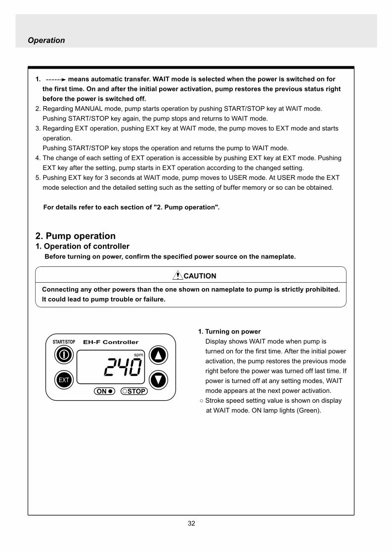
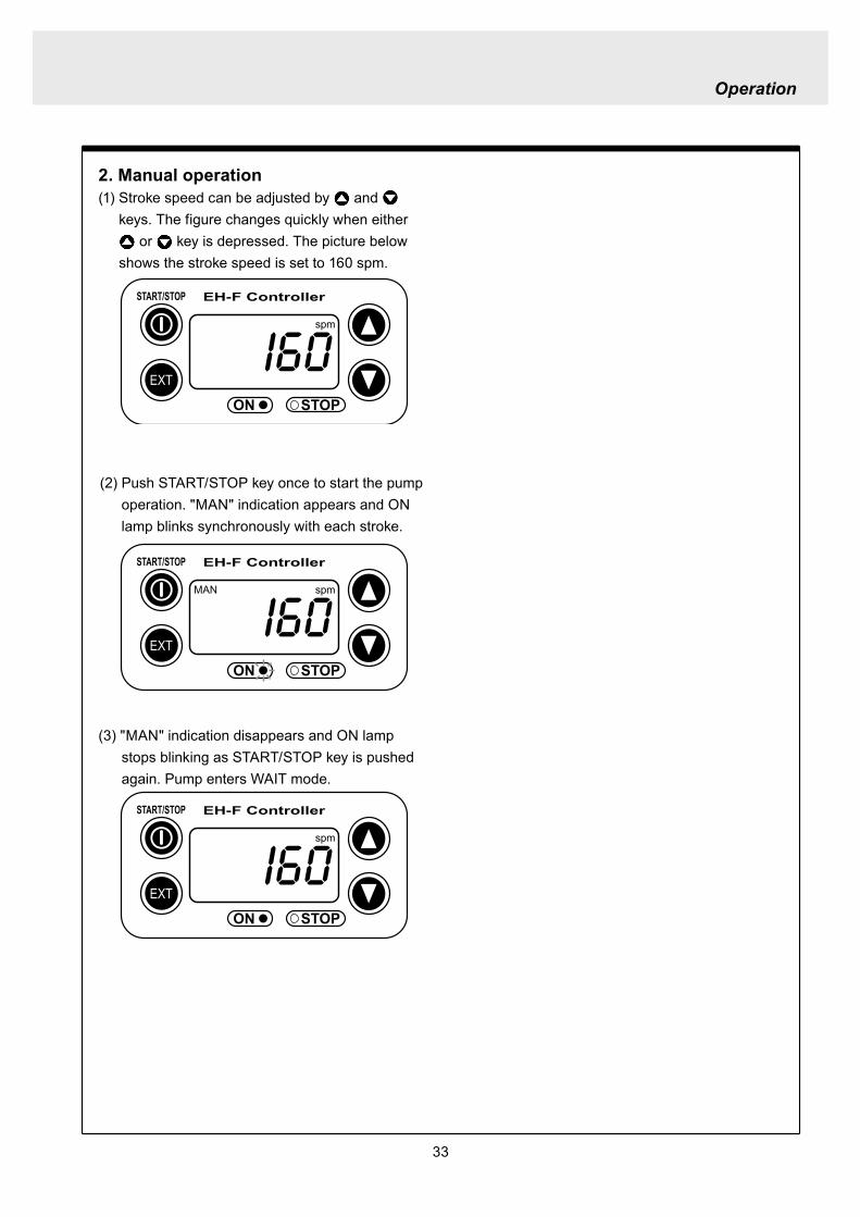
33
2 Manual operation(1) Stroke speed can be adjusted by and
keys The figure changes quickly when either or key is depressed The picture below
shows the stroke speed is set to 160 spm
EXT
EH-F ControllerSTARTSTOP
ON STOP
spm
EXT
EH-F ControllerSTARTSTOP
ON STOP
MAN spm
EXT
EH-F ControllerSTARTSTOP
ON STOP
spm
(2) Push STARTSTOP key once to start the pump operation MAN indication appears and ON lamp blinks synchronously with each stroke
(3) MAN indication disappears and ON lamp stops blinking as STARTSTOP key is pushed again Pump enters WAIT mode
Operation
Operation
34
EXT
EH-F ControllerSTARTSTOP
ON STOP
ANA V
P1 SET mA
EXT
EH-F ControllerSTARTSTOP
ON STOP
P1 SET
ANA V spm
EXT
EH-F ControllerSTARTSTOP
ON STOP
spm
EXT
EH-F ControllerSTARTSTOP
ON STOP
ANA V spm
(4) Set the current value at P1 Figure increases or decreases as or key is pushed The pic-ture below shows 80 mA is set to point 1
EXT
EH-F ControllerSTARTSTOP
ON STOP
ANA V
P1 SET mA
(5) Pushing EXT key once spm appears on the display while mA disappears The picture below shows the number of strokes at P1
EXT
EH-F ControllerSTARTSTOP
ON STOP
P1 SET
ANA V spm
3 EXT operation (ANA V mode)(1) Push STARTSTOP key to move to WAIT mode
if pump is in another mode Go to next step if pump is in WAIT mode
(2) ANAV indication appears and pump enters an EXT mode as EXT key is pushed once Pump starts operation in accordance with current sig-nals and various settings ON lamp blinks at each pumping during operation Pump is con-trolled via the EXT mode which was select-ed at USER mode The initial setting of EXT mode is ANA V mode Select a preferable EXT mode in USER mode The picture below shows ANA V mode (The spm on the display changes according to input signals)
(3) Push EXT key once when pump is running in ANA V mode Display indicates the setting display of ANA V mode spm indication dis-appears and P1 SET and mA indications appear on the screen
(6) Set the number of strokes at P1 Figure increasesdecreases as key is pushed Picture below shows 10 spm is set for point 1
Operation
35
(7) Push EXT key to move to the setting display of the current value at P2 P1 and spm disap-pear and P2 and mA appears instead
EXT
EH-F ControllerSTARTSTOP
ON STOP
ANA V
P 2 SET mA
EXT
EH-F ControllerSTARTSTOP
ON STOP
ANA V
P 2 SET mA
EXT
EH-F ControllerSTARTSTOP
ON STOP
P 2 SET
ANA V spm
(11) Push EXT key to return to EXT mode Pump starts to run in ANA V mode on the setting of (4) through (10) ON lamp starts to blink at each pumping
EXT
EH-F ControllerSTARTSTOP
STOPON
ANA V spm
EXT
EH-F ControllerSTARTSTOP
ON STOP
P 2 SET
ANA V spm
EXT
EH-F ControllerSTARTSTOP
ON STOP
spm
(8) Set the current value of P2 by pushing and keys Picture below shows 180 mA is set to
point2
(9) Pushing EXT key once spm appears on the display while mA disappears The picture below shows the number of strokes at P2
(10) Set the number of strokes at P2 by pushing and keys Picture below shows 200
spm is set to point 2
(12) Pushing STARTSTOP key pump enters WAIT mode and pump stops ON lamp stops blink-ing and ANAV indication disappears
CAUTIONWhen the setting of the buffer memory is OFF keep the number of strokes in the dividing operation 240 spm or below The input signals to operate the pump over 240 spm can cause an unstable pump operationWhen the setting of the buffer memory is ON the pump operates for all the input pulse signalsPump keeps operating after all the signals are stopped in this case Be careful when setting of buffer memory
Operation
36
EXT
EH-F ControllerSTARTSTOP
ON STOP
DIV
SET
EXT
EH-F ControllerSTARTSTOP
ON STOP
DIV
SET
EXT
EH-F ControllerSTARTSTOP
STOPON
DIV spm
EXT
EH-F ControllerSTARTSTOP
ON STOP
spm
(2) Pushing EXT key DIV appears and pump starts operation in the ratio of input pulse sig-nals a pumping ON lamp blinks synchronous-ly at each pumping The initial setting of EXT selection is ANA V mode Change mode to DIV mode via USER mode Refer to P 40 for detail information
(3) Push EXT key while pump is operating in DIV mode Pump stop running and SET indication appears on the DIV setting display in stead of spm indication
(4) Enter a dividing ratioFigure increasesdecreases when key is pushed The picture below shows 10 is set
4 EXT operation (DIV mode)
(1) Push STARTSTOP key to move to WAIT mode if pump is in another mode Go to next step if pump is in WAIT mode
CAUTIONOn condition the setting of buffer memory is OFF do not input any pulse signals during the pumping motions for a input pulse signal in the multiply operation These input pulse signals are cancelledWhen the setting of buffer memory is ON pump operates for all the input pulse signals
Operation
37
EXT
EH-F ControllerSTARTSTOP
ON STOP
spm
EXT
EH-F ControllerSTARTSTOP
STOPON
DIV spm
EXT
EH-F ControllerSTARTSTOP
ON STOP
spm
EXT
EH-F ControllerSTARTSTOP
ON STOP
MULT
(5) Push EXT key to return to EXT operating mode Pump starts to run on the setting at item (4) ON lamp blinks synchronously at each pumping
(6) Pushing STARTSTOP key pump enters WAIT mode and pump stopsDIV indication disappears and ON lamp stops blinking
5 EXT operation (MULT mode)
(2) MULT indication appears and pump starts running in an EXT operation mode in the ratio of an input pulse signal pumpings as press-ing EXT key ON lamp blinks at each pump-ing Display shows the rest of the number of strokes In MULT mode the number of strokes is equal to the setting value in manual opera-tionThe initial setting of the EXT mode selection is ANA V mode which is the operation in pro-portion to current First select MULT mode via USER mode Refer to P 40 for detail informa-tion
(1) Push STARTSTOP key to move to WAIT mode if pump is in another mode Go to next step if pump is in WAIT mode
Operation
38
EXT
EH-F ControllerSTARTSTOP
ON STOP
spmEXT
EH-F ControllerSTARTSTOP
ON STOP
ANAR spm
EXT
EH-F ControllerSTARTSTOP
ON STOP
MULT
SET
EXT
EH-F ControllerSTARTSTOP
ON STOP
MULT
EXT
EH-F ControllerSTARTSTOP
ON STOP
spm
EXT
EH-F ControllerSTARTSTOP
ON STOP
MULT
SET
(5) Push EXT key to return to MULT mode(3) Pushing EXT key when pump is running in the multiply operation calls the setting display of MULT mode and SET indication appearsPump stops running and ON lamp stop blinking
(4) Enter the number of pumpings per input signalFigure increasesdecreases when key is pushed The picture below shows the pump-ing number is set to 1800 times per an input signal
6 EXT operation (ANA R mode)(1) Push STARTSTOP key to move to WAIT mode
if it is in another mode Go to next step if it is in WAIT mode
(6) Pushing STARTSTOP key recalls WAIT mode and pump stops spm indication appears in stead of MULT indication
(2) Pushing EXT key ANAR appears and pump starts running in the ratio of an input pulse sig-nal pumpings ON lamp blinks at each pump-ing The initial setting of the EXT mode selec-tion is ANA V mode which is the operation in proportion to current is selected First select ANA R mode in USER mode Refer to P 40 for more information
Operation
39
EXT
EH-F ControllerSTARTSTOP
ON STOP
ANAR
SET mA
EXT
EH-F ControllerSTARTSTOP
ON STOP
ANAR spm
EXT
EH-F ControllerSTARTSTOP
ON STOP
ANAR
SET mA
EXT
EH-F ControllerSTARTSTOP
ON STOP
spm
(4) Figure increasesdecreases when key is pushed The picture below is when it is set to 0-240 spm for 20-4 mA
(5) Push EXT key to return to EXT mode Pump starts to run on the setting at item (4) ON lamp blinks synchronously at each pumping
(6) When pushing STARTSTOP key pump enters WAIT mode and stops running ON lamp stops blinking and ANAR disappears
(3) Pushing EXT key when pump is running in the multiply operation calls the setting display of ANAR mode and SET and mA indications appear while spm disappears Pump stops running and ON lamp stops blinking
Operation
40
EXT
EH-F ControllerSTARTSTOP
ON STOP
ANA V
(5) Push EXT key to confirm the desired EXT mode Pump displays the EXT mode selection The picture below shows DIV appears to indi-cate DIV mode is selected
EXT
EH-F ControllerSTARTSTOP
ON STOP
DIV
EXT
EH-F ControllerSTARTSTOP
ON STOP
SET
EXT
EH-F ControllerSTARTSTOP
ON STOP
spm
EXT
EH-F ControllerSTARTSTOP
ON STOP
spm
EXT
EH-F ControllerSTARTSTOP
ON STOP
SET
7 USER settingThe setting of each function is changed in USER mode Have the pump entering WAIT mode in order to move to USER mode OUT (Output) is synchronous with spm and it can not be changed
7-1 EXT mode selection Any one of DIV (pulse dividing) MULT (pulse multiply) ANAR (analog rigid) or ANAV (analog vari-able) can be active in EXT mode The initial mode when shipped from factory is ANAV
(1) Push STARTSTOP key to move to WAIT mode if it is in another mode If it is in WAIT mode go to next step
(2) Press EXT key for more than 3 seconds to move to USER mode The picture below shows pump enters the EXT mode selection
(3) Pushing EXT key SET appears and display shows the mode currently set Picture below shows ANA V mode is selected
(4) Push or key to select a desired EXT mode The picture below shows DIV mode is selected
(6) Push STARTSTOP key to move to WAIT mode spm appears while DIV goes out
Operation
41
EXT
EH-F ControllerSTARTSTOP
ON STOP
spm
EXT
EH-F ControllerSTARTSTOP
ON STOP
ANA V
EXT
EH-F ControllerSTARTSTOP
ON STOP
SET
(3) Push key once
EXT
EH-F ControllerSTARTSTOP
ON STOP
(4) Push key again to move to the anti-chatter-ing setting display
EXT
EH-F ControllerSTARTSTOP
ON STOP
(5) Pushing EXT key display shows the mode cur-rently set and SET appears on it The picture below shows when MECH is selected
EXT
EH-F ControllerSTARTSTOP
ON STOP
SET
7-2 Setting of anti-chattering Anti-chattering function is settable against the incoming pulses during the DIV or MULT operation For the long chattering of mechanical contact such as relay set a large figure via MECH For the high speed (high frequency) chattering of the semi-conductor type contact such as transistor set a small figure via ELEC ST05 of MECH is initial setting
(6) Select MECH by or key for a mechani-cal contact And select ELEC for a semi-conductor contact The picture below shows ELEC is selected
(1) Push STARTSTOP key to move to WAIT mode if it is in another mode If it is in WAIT mode go to next step
(2) Press EXT key for more than 3 seconds to move to USER mode The picture below shows pump enters the EXT mode selection
Operation
42
EXT
EH-F ControllerSTARTSTOP
ON STOP
SET
(7) Push EXT key to display the current set state The picture below shows FT01 is selected
EXT
EH-F ControllerSTARTSTOP
ON STOP
SET EXT
EH-F ControllerSTARTSTOP
ON STOP
EXT
EH-F ControllerSTARTSTOP
ON STOP
spm
7-3 Setting of buffer memoryIn case pump operation can not catch up with the input pulse signals in DIV or MULT operation exces-sive pulse signals can be put in memory up to 65535 pulses However the excessive pulses can not be restored if once power is off or mode is changed
EXT
EH-F ControllerSTARTSTOP
ON STOP
spm
(2) Press EXT key for 3 seconds or more to move to USER mode The picture below shows the EXT mode selection display
EXT
EH-F ControllerSTARTSTOP
ON STOP
ANA V
(8) Set a large figure for the long chattering by or key and set a small figure for high speed (high frequency) chattering The picture below shows FT04 is selected
(9) Push EXT key to return to the anti-chattering setting display SET indication disappears
(10) Push STARTSTOP key to return to wait mode spm indication appears
(1) Push STARTSTOP key to move to WAIT mode if it is in another mode If it is in WAIT mode go to next
Operation
43
(3) Push key once
EXT
EH-F ControllerSTARTSTOP
ON STOP
(7) Push or key in order to set buffer memo-ry to ON or OFF Select MEM-Y to set it ON Select MEM-N for OFF setting The picture below shows when ON is set
EXT
EH-F ControllerSTARTSTOP
ON STOP
SET
(4) Push key once again
EXT
EH-F ControllerSTARTSTOP
ON STOP
(8) Push EXT key to return to the buffer memory setting display SET indication disappears
EXT
EH-F ControllerSTARTSTOP
ON STOP
(9) Push STARTSTOP key to return to WAIT mode spm indication appears
EXT
EH-F ControllerSTARTSTOP
ON STOP
spm
(5) Push key once again and the buffer memory setting display is shown
EXT
EH-F ControllerSTARTSTOP
ON STOP
(6) Push EXT key in order to display the current set state SET indication appears The picture below shows the buffer memory is set to OFF
EXT
EH-F ControllerSTARTSTOP
ON STOP
SET
Operation
44
8 Bleeding amp self-primingAt WAIT mode Manual operating mode and EXT operating mode pump operates at max speed tak-ing priority over any functions when both and keys are pushed at once Pump runs at max speed only when both keys are depressed Pump state returns to the previous mode once either or key is released Pressing and keys for 10 seconds keeps pump running at maximum speed In this state this fixation is released when pushing either or key once and pump returns to the previous mode
(1) When pump is running in ANAV mode
EXT
EH-F ControllerSTARTSTOP
ON STOP
ANA V spm
(2) Pump start to run at full speed when and keys are pressed at once Display shows
PRIME If either or key is released pump returns to the previous mode In this case pump returns to ANAV mode
EXT
EH-F ControllerSTARTSTOP
ON STOP
ANA V
(3) Pressing both and keys simultaneously for 10 seconds or more pump continues to run at full speed even if both keys are released In this case indication appearsPush either or key to release this state indication disappears and pump returns to the previous mode In this case pump returns to ANAV mode
EXT
EH-F ControllerSTARTSTOP
ON STOP
ANA V
Operation
45
10 Error display and release(1) In case Input signals fall to 4 mA or below while
4-20 or 20-4 is set to ANA R mode pump stops with DISCN blinking and Err on dis-play
(2) This error state can be released by push-ing STARTSTOP key and pumps enters wait mode In this case check the wiring and input signals
EXT
EH-F ControllerSTARTSTOP
ON STOP
ANAR
Err
spm
EXT
EH-F ControllerSTARTSTOP
ON STOP
spm
9 Key lockKey lock function is to prevent pump from being operated by some other person than user If STARTSTOP key is pressed for five seconds or more when pump is running or stops all key operations become ineffective with LOCK indication on display This function can be released by pressing STARTSTOP key for 5 seconds while LOCK lights
EXT
EH-F ControllerSTARTSTOP
ON STOP
MAN spm
LOCK
46
Do not conduct a maintenance work with the wet hands It can cause an electric shock
Before dismantling pump be sure to turn off power and check the pump is not electrified Do not
start a dismantlement work after stopping the pump by pushing the STARTSTOP key only Put up
the sign of ldquoMaintenance work is in progressrdquo in order to prevent a pump switch from turning on
unintentionally during the work Release the pressure of discharge piping and drain the liquid from
the wet end parts And then clean the inside of pump head
Wear protective clothing such as a protective mask globes goggles and chemical-proof wear
according to the handled chemical liquid during the work
WARNING
5 Maintenance
1 Trouble shootingTrouble Cause Troubleshooting
Pump dose not start Faulty wiring or disconnection in wiring Voltage is too low Failure in the electronic circuit of control unit
Pump dose not suck liquidDischarge amount is low
Air suction from suction piping Valve gasket is not installed Valve set assembling direction is wrong Pump is air-locked Pump stroke length is too short Suction-sidedischarge-side valve is clogged with
foreign matter Adhesion of valve onto valve seat
Discharge amount fluctuates
Liquid leaks
Key operation is ineffective Key is locked Release key lock
Pump doesnt run
Pump is in waiting mode Signals are not coming for EXT operation Pump is in EXT setting mode Pump is suspended with STOP
Move to operation mode Check wiring and correct the wrong part Move to EXT operating mode Release STOP function
Abnormal noise
Suction-sidedischarge-side valve is clogged with foreign matters
The sound absorption gasket is worn out Bearing is worn out Spring is damaged
Piping vibrates due to pulsation Bearing is worn out Spring is damaged
Install a accumulator or an air chamber The end of pump life span The end of pump life span
Suction-sidedischarge-side valve is clogged with foreign matters
Air is trapped in pump Overfeeding Diaphragm is damaged
Fittings are not tightly closed Pump head is not tightened Diaphragm is damaged O ring and valve gasket are not installed O ring is damaged
Correct wiring Inspect power source and provide measurement Replace the whole unit
Arrange piping again Install valve gasket Reassemble valve set Carry out air elimination Drive pump with 100 stroke length to prime liquid Then
reset stroke length Disassemble inspect and clean Disassemble inspect and clean
Tighten fittings Tighten pump head Replace diaphragm Install O ring and valve gasket Replace O ring
Disassemble inspect and clean
Carry out air elimination Install a check valve or a back pressure valve Replace diaphragm
Disassemble inspect and clean
The end of pump life span The end of pump life span The end of pump life span
Abnormal vibration
Input pulse can not be read Signals are not coming Anti-chattering setting is not proper
Check wiring and correct the wrong part Change the setting properly
Analog signal input can not be read
Wrong wiring Signals are over acceptable loaded resistance
Check wiring and correct wrong part The load resistance is 200Ω Use some devise which can
accept the load resistance
47
CAUTION Check periodically whether the bolts fixing pump head are tightened Tighten them as needed
The bolts fixing pump head may loosen in operation Tightening torque 255Nbullm
Maintenance
3
bull Tighten joint where leakage has occurredbull The excessive air bubbles in the discharged liquid mean air suc-
tion has been caused in system Examine the piping and tighten joint on where leaks
Is there liquid leakage or air suction at any joints on pump or piping
2 Maintenance and inspection
1 Daily inspectionPay attention to the following points during pump operation Stop pump immediately upon detecting abnormality and take measures according to the item Troubleshooting When wear parts come to the life time replace them by new ones
No
1
2
Check Point Description
Does pump lift liquid normally
bull Is liquid normally fedbull Is suction pressuredischarge pressure at normal levelbull Has liquid undergone quality change crystallization or solidifica-
tion
Abnormal noise or vibrationbull Abnormal noise or vibration may happen from the abnormal func-
tioning of pump
EXT setting can not be stored
After EXT setting STARTSTOP key is pushed for EXT by mistake
Push EXT key to operate pump in EXT mode
ldquoPRIME is kept indicated and other operations are inac-cessible
Self-priming function is active Push either or key to release the function
Analog signal input can not be read and DISCN indication appears
Wrong wiring or disconnection Check wiring and correct the wrong part Refer to page 45
for how to release an error indication
Trouble Cause Troubleshooting
48
Maintenance
2 Wear partsWear parts should be replaced in proper period for a long period of pump operation It is recommended that follow-ing parts are always ready for the replacementVC V6 PC P6 types
Parts Qty Life span
Pum
p he
ad
Valve set
EH-F35 EH-F45 EH-F55middot70
2sets
8000hours
Diaphragm 1
Refer to exploded view
Bac
k pr
essu
re v
alve
1
2
Che
ck v
alve
7 6 1
8 11 1
Diaphragm seat 1
O ring
Poppet check valve (With check gasket)
Check valve spring Spacer
Diaphragm
O ring
Note Durability of wear parts depend on the pumped liquid temperature and pressure Time to be replaced mentioned as above is the estimation obtained by continuous pump-ing of clean water at ambient temperature
8000hours
4000hours
49
3 Dismantlement and assembly
Getting wet with or coming in contact with chemicals and toxic liquid is harmful Wear protective clothing such as a protective mask globes goggles and chemical-proof wear during the work
Risk of electrical shock Be sure to turn off power and confirm that pump and devices are not electrified before the work
Release the pressure inside pump and a discharge hose by opening an air bleed valve on piping prior to loosening the piping connections or the dismantlement of pump Dismantlement with the pressure inside pump could lead to liquid spillage
Be careful not to touch residual liquid when dismantling pump Some liquids are harmful for skin or component parts Wipe off liquid when the hand or the component parts come in contact with liquid
WARNING
CAUT ION
Hose
Hose stopperFitting spacer
O ring
Fitting nut
Fitting
Pumphead
Remove the fittingwith a spanner
1 Valve set replacement Dismantlement1 Loosen a fitting nut and remove the hose con-
nected to pump head Pay attention to the liquid dripping
2 Loosen a fitting with a spanner to remove it Then detach the valve set from pump head
Maintenance
50
AssemblyAssembly procedure is in reverse order to disas-sembly Pay attention to the following when assembling valve set DispositionInsertion direction of valve set The wrong dispositioninsertion direction of valve
set component can lead to leakage and less dis-charge amount
O ring is fitted properly1 Discharge side valve set mounting
Put valve set in pump head and screw a fitting into a pump head by hand and then re-tighten it by 14 turns with a spanner
2 Suction side valve set mountingPut valve set in connection port and screw the fitting into pump head by hand and then re-tighten it by 14 turns with spanner
Note Pay attention to the mounting direction of the spacer fitted to EH-F45(VC V6 PC)Make sure the cut portion on the spacer of suction side should be downward the one of discharge side should be upward
Suction side
Discharge side
O ringValve gasket
Valve gasket
Valve gasket
Valve guideValveValve seatSpacer
O ring
Valve gasketValve guideValveValve seat
Spacer
1714
11
1312
11
1312
17
17
14
14
14
11
31
1312
31
17
14
11
1312
12
13
11
14
EH-F35
EH-F45
EH-F5570
Suct
ion
side
Dis
char
ge s
ide
For b
oth
suct
ion
and
disc
harg
e si
deFo
r bot
h su
ctio
nan
d di
scha
rge
side
VC V6 PC P6 Type
Maintenance
51
Pay attention not to lose diaphragm spacer and to apply the correct number of diaphragm spacers 0 to several pieces of diaphragm spacers are put between retainer and plunger to adjust the position of diaphragm The number of spacers mounted depends on the pump model There are the models which do not have spacers
Maintenance
2 Diaphragm replacement Dismantlement1 Set stroke length to 0 by adjusting stroke length
adjustment knob
2 Remove the pump head from the pump body by loos-ening hex socket cap bolts
3 Rotate a diaphragm anti-clockwise to remove it from a plunger pin The diaphragm is screwed into the plunger pin
AssemblyAssembly is done in reverse order to disassembly Follow the steps below1 Make sure the stroke length of pump is set to 0
prior to an assembly Operate pump to set the stroke length to 0 and
stop it Then turn off power
2 Fit a rear diaphragm seat a retainer and a diaphragm spacer into new diaphragm via the threaded pin and screw the diaphragm into the plunger pin
Fit the concave side of retainer into the convex side of diaphragm Pay attention the retainer dose not come off
3 Set the stroke length to 100 Operate pump to set the stroke length to 100
and stop it Then turn off power4 Install a pump head to a pump body by tightening
the hex sock cap bolts equally Tightening torque is 255Nbullm
52
4 Accessories1 Connection port bore bull Check valve bull Back pressure valve
Note1 Check valves and back pressure valves are options2 Regarding the connection of the discharge side of back pressure valve
NPT38 and NPT12 taper pipe thread is used for BV-N-CR
Pump type Connection port bore Check valve Back pressure valve
EH-F35VC empty38timesempty12 hose CA-3VCH-C6 ndash
empty38timesempty12 hose CA-3VEH-C6 ndashempty38timesempty12 hose CA-3VH-C6 ndashempty38timesempty12 hose CA-3VCH-C6 ndashempty38timesempty12 hose CA-3VEH-C6 ndashempty38timesempty12 hose CA-3VH-C6 ndash
V6
empty38timesempty12 hose ndash BV-3NV-C6Rempty38timesempty12 hose ndash BV-3NE-C6Rempty38timesempty12 hose ndash BV-3NPV-C6Rempty58timesempty34 hose ndash BV-3NV-C7Rempty58timesempty34 hose ndash BV-3NE-C7Rempty58timesempty34 hose ndash BV-3NPV-C7R
PC
EH-F45VCV6PC
EH-F55VCV6PC
EH-F70VCV6PC
Maintenance
53
Maintenance
5 Exploded view
1 General view The extent of dismantlement is within the following exploded view
Diaphragm spacer
Retainer
(Back up retainer)55 bull 70 types
Pump body
Valve set
Valve set
Pump head
Diaphragm
Rear diaphragm sheet
54
2 Pump head (Hose connection type)
EH-F45 type EH-F35 type
4
28
2930
3
1114
131211
131217
1897
1
17
111312111312
3
3029
28
4
1920
1920 21
17
111312
31
3
3029
28
4
131217
189
7
11
3114
14
4
282930
3
1
21
1515
EH-F55 type
4
28
2930
3
11
131217
18
9
7
10
1
1920 21
17
111312
3
30
29
28
4
EH-F70 type
4
28
2930
3
14
11131217
18
9
7
10
1
1920 21 17
111312
3
30
29
28
4
15 15
14
1414
14
14 14
Note1 The back up retainer of No10 is only for EH-F55 bull 70 typesNote2 The figure inside ( ) in the above table is for EH-F45 bull 55 bull 70 typesNote3 The number of the diaphragm spacers (No18) is not constant None or a few spacers is inserted at
each diaphragmNote4 The figure inside ( ) in the above table is for EH-F70Note5 EH-F35 bull 55 bull 70 (VC V6 PC ) types require 2 valve gaskets and EH-F45 (VC V6 PC) types
require 4 of themNote6 The spacer on No31 is for EH-F45 type only
No Name Qty1 Pump head 13 Fitting 24 Fitting nut 27 Diaphragm 19 Retainer 110 Back up retainer 1 Note111 Valve guide 4 (2) Note212 Valve seat13 Valve14 Valve gasket
No Name Qty
17 O ring 218 Diaphragm spacer 1 Note319 Hex socket head bolt 6 (8) Note420 Spring washer21 Plain washer28 Hose stopper 229 Fitting spacer 230 O ring 231 Spacer 2 Note6
15 Rear diaphragm seat 1
2 (4) Note54 (2) Note24 (2) Note2
6 (8) Note46 (8) Note4
Maintenance
55
Maintenance
3 Pump head (Flange connection type) EH-F55 type
30
3
11
131217
18
9
7
10
1
1920 21
17
11
1312
3
30
EH-F70 type
15
EH-F45 type EH-F35 type
30
3
11131211
131217
1897
1
17
11131211
1312
3
30
1920
1920 21
17
111312
31
3
131217
189
7
11
31
30
3
1
30
21
1515
30
3
11131217
18
9
7
10
1
1920 21 17
11
1312
3
30
15
32
33
33
32
4
32
433
43332
32
334
43332
32
33
32
334
44
1414
14 14 14
1414
14
14 14
NoNo Name Qty1 Pump head 13 Fitting 24 Fitting nut 27 Diaphragm 19 Retainer 110 Back up retainer 1 Note111 Valve guide 4(2)Note212 Valve seat 4(2)Note213 Valve 4(2)Note214 Valve gasket 2(4)Note5
Name Qty
17 O ring 218 Diaphragm spacer 1 Note319 Hex socket cap bolt 6(8)Note420 Spring washer 6(8)Note421 Plain washer 6(8)Note430 O ring 2
33 Union 2
31 Spacer 2 Note6
15 Rear diaphragm seat 1
32 Flange 2
Note1 The back up retainer of No10 is only for EH-F55 bull 70 typesNote2 The figure inside ( ) in the above table is for EH-F45 bull 55 bull 70 typesNote3 The number of the diaphragm spacers (No18) is not constant None or a few spacers is inserted at
each diaphragmNote4 The figure inside ( ) in the above table is for EH-F70Note5 EH-F35 bull 55 bull 70 (VC V6 ) types require 2 valve gaskets and EH-F45 (VC V6) types require 4 of
themNote6 The spacer on No31 is for EH-F45 type only
56
4 Pump head (Flange connection horizontal suction port type) EH-F55 type
30
3
11
131217
18
9
7
10
1
1920 21
17
111312
3
30
EH-F70 Type
15
EH-F45 Type EH-F35 type
30
3
11131211
131217
1897
1
17
111312111312
3
30
1920
1920 21
17
11131231
3
131217
189
7
11
31
30
3
1
30
21
1515
30
3
11131217
18
9
7
10
1
1920 21 17
111312
3
30
15
32
33
32
433
43334
32
32
334
43334
32
33
44
34
32
334
34
32
334
32
35 353535
1414
14 14 14
1414
14
14 14
No Name Qty1 Pump head 13 Fitting 24 Fitting nut 27 Diaphragm 19 Retainer 110 Back up retainer 1 Note111 Valve guide 4 (2) Note212 Valve seat13 Valve
15 Rear diaphragm sheet 114 Valve gasket
No Name Qty
18 Diaphragm spacer 1 Note319 Hex socket cap bolt20 Spring washer21 Plain washer
31 Spacer 2 Note6
35 Pipe 1
32 Flange 2
34 Elbow 133 Union 2
17 O ring 2
30 O ring 2
4 (2) Note24 (2) Note22 (4) Note5
6 (8) Note4
4 (2) Note24 (2) Note2
Maintenance
Note1 The back up retainer of No10 is only for EH-F55 bull 70 typesNote2 The figure inside ( ) in the above table is for EH-F45 bull 55 bull 70 typesNote3 The number of the diaphragm spacers (No18) is not constant None or a few spacers is inserted at
each diaphragmNote4 The figure inside ( ) in the above table is for EH-F70Note5 EH-F35 bull 55 bull 70 (VC V6) types require 2 valve gaskets and EH-F45 (VC V6) types require 4 of
themNote6 The spacer on No31 is for EH-F45 type only
57
5 Check valve CA-3 type
1 2 3 4 5 6 7 8 11 9 10
16
14
13
15
12
3
15
17
16
1110
98
7
1
54
2
6
14
13
6 Back pressure valve BV-3N-R type
No No Name Qty10 Stopper 111 Diaphragm 112 Lower case 113 Fitting spacer Hose port 114 Hose stopper Ferrule 115 O ring 216 Nut 217 Fitting 1
Name Qty1 Upper case 12 Hexhead bolt (with PW SW) 43 Hex nut 44 Adjusting bolt 15 Hexnut 16 Plain washer 1
8 Spring 19 Retainer plate 1
7 Spring seat 1
NoNo Name Qty1 Fitting nut 12 Hose stopper 13 Fitting spacer 14 O ring 15 Valve case 16 Gasket 1
Name Qty7 Poppet valve 18 Spring 19 O ring 110 Valve fitting 111 Spacer 1
Maintenance
58
Maintenance
1 Outer dimension (Hose connection type) EH-F35 type
TUBING(38rdquotimes12rdquo)
38rdquotimes12rdquo
EH-F45 type
38rdquotimes12rdquo
38rdquotimes12rdquo
59
EH-F55 type
58rdquotimes34rdquo
58rdquotimes34rdquo
EH-F70 type
Maintenance
38rdquotimes12rdquo
38rdquotimes12rdquo
60
Maintenance
2 Outer dimension (Flange connection type) EH-F35 type
EH-F45 type
61
EH-F55 type
EH-F70 type
Maintenance
62
Maintenance
3 Outer dimension (Flange connection horizontal suction port type) EH-F35 type
EH-F45 type
63
EH-F55 type
EH-F70Type
Maintenance
httpwwwiwakipumpsjp
Read this manual before use of product
IWAKIElectromagnetic Metering Pump
EH-F series (North America)
Instruction ManualT596 0706
GermanyItalyDenmarkSwedenFinlandNorwayFranceUKSwitzerlandAustriaHollandSpainBelgiumUSA
TEL (49)2154 9254 0TEL (39)02 990 3931TEL (45)48 24 2345TEL (46)8 511 72900TEL (358)9 2742714TEL (47)66 81 16 60TEL (33)1 69 63 33 70TEL (44)1743 231363TEL (41)26 674 9300TEL (43)2236 33469TEL (31)297 241121TEL (34)943 630030TEL (32)1367 0200TEL (1)508 429 1440
AustraliaSingaporeIndonesiaMalaysiaTaiwanThailandHong KongChinaChinaChinaChinaPhilippinesKoreaVietnam
TEL (61)2 9899 2411TEL (65)6316 2028TEL (62)21 690 6606TEL (60)3 7803 8807TEL (886)2 8227 6900TEL (66)2 322 2471TEL (852)2 607 1168TEL (86)750 380 9018TEL (86)20 8435 0603TEL (86)10 6442 7713TEL (86)21 6272 7502TEL (63)2 888 0245TEL (82)2 3474 0523TEL (84)613 933456
IWAKI EUROPE GmbH IWAKI Italia SRL IWAKI Nordic AS IWAKI Sverige AB IWAKI Suomi Oy IWAKI Norge AS IWAKI France SA IWAKI PUMPS (UK) LTD IWAKI (Schweiz) AG IWAKI (Austria) GmbH IWAKI Holland BV IWAKI Iberica Pumps SA IWAKI Belgium nv IWAKI America Incorporated
FAX 2154 1028FAX 02 990 42888FAX 48 24 2346FAX 8 511 72922FAX 9 2742715FAX 66 81 16 61FAX 1 64 49 92 73FAX 1743 366507FAX 26 674 9302FAX 2236 33469FAX 297 273902FAX 943 628799FAX 1367 2030FAX 508 429 1386
IWAKI Pumps Australia Pty Ltd IWAKI Singapore Pte Ltd IWAKI Singapore (Indonesia Branch) IWAKIm Sdn Bhd IWAKI Pumps Taiwan Co Ltd IWAKI (Thailand) CoLtd IWAKI Pumps Co Ltd IWAKI Pumps (Guandong) Co Ltd GFTZ IWAKI Engineering amp Trading (Guangzhou) IWAKI Pumps Co Ltd (Beijing) IWAKI Pumps (Shanghai) Co Ltd IWAKI Chemical Pumps Philippines Inc IWAKI Korea CoLtd IWAKI Pumps Vietnam Joint Venture CoLtd
FAX 2 9899 2421FAX 6316 3221FAX 21 690 6612FAX 3 7803 4800FAX 2 8227 6818FAX 2 322 2477FAX 2 607 1000FAX 750 380 9078FAX 20 8435 9181FAX 10 6442 7712FAX 21 6272 6929FAX 2 843 3096FAX 2 3474 0221FAX 613 933399
( )Country codes
IWAKI COLTD 6-6 Kanda-Sudacho 2-chome Chiyoda-ku Tokyo 101-8558 JapanTEL(81)3 3254 2935 FAX3 3252 8892(httpwwwiwakipumpsjp)
This is patent pending product
- 107
- 47
- 48
- 49
- 50
- 3
- 4
- 64
- 102
- 101
- 78
- 79
- 91
- 81
- 100
- 99
- 84
- 86
- 85
- 87
- 22
- 23
- 73
- 72
- 26
- 98
- 28
- 27
- 31
- 32
- 29
- 30
- 95
- 34
- 33
- 96
- 35
- 36
- 37
- 38
- 40
- 39
- 41
- 42
- 59
- 58
- 45
- 7
- 6
- 46
- 5
- 8
- 9
- 74
- 75
- 10
- 11
- 61
- 60
- 15
- 14
- 62
- 63
- 16
- 17
- 18
- 19
- 92
- 94
- 93
- 103
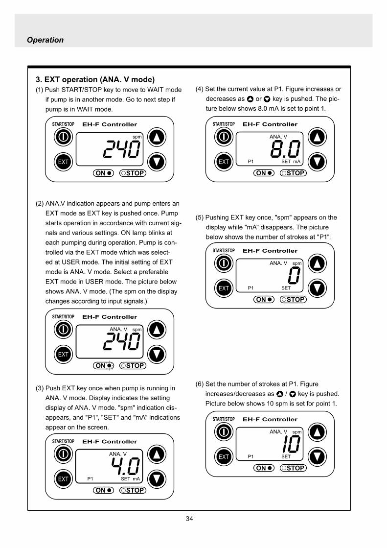
Operation
34
EXT
EH-F ControllerSTARTSTOP
ON STOP
ANA V
P1 SET mA
EXT
EH-F ControllerSTARTSTOP
ON STOP
P1 SET
ANA V spm
EXT
EH-F ControllerSTARTSTOP
ON STOP
spm
EXT
EH-F ControllerSTARTSTOP
ON STOP
ANA V spm
(4) Set the current value at P1 Figure increases or decreases as or key is pushed The pic-ture below shows 80 mA is set to point 1
EXT
EH-F ControllerSTARTSTOP
ON STOP
ANA V
P1 SET mA
(5) Pushing EXT key once spm appears on the display while mA disappears The picture below shows the number of strokes at P1
EXT
EH-F ControllerSTARTSTOP
ON STOP
P1 SET
ANA V spm
3 EXT operation (ANA V mode)(1) Push STARTSTOP key to move to WAIT mode
if pump is in another mode Go to next step if pump is in WAIT mode
(2) ANAV indication appears and pump enters an EXT mode as EXT key is pushed once Pump starts operation in accordance with current sig-nals and various settings ON lamp blinks at each pumping during operation Pump is con-trolled via the EXT mode which was select-ed at USER mode The initial setting of EXT mode is ANA V mode Select a preferable EXT mode in USER mode The picture below shows ANA V mode (The spm on the display changes according to input signals)
(3) Push EXT key once when pump is running in ANA V mode Display indicates the setting display of ANA V mode spm indication dis-appears and P1 SET and mA indications appear on the screen
(6) Set the number of strokes at P1 Figure increasesdecreases as key is pushed Picture below shows 10 spm is set for point 1
Operation
35
(7) Push EXT key to move to the setting display of the current value at P2 P1 and spm disap-pear and P2 and mA appears instead
EXT
EH-F ControllerSTARTSTOP
ON STOP
ANA V
P 2 SET mA
EXT
EH-F ControllerSTARTSTOP
ON STOP
ANA V
P 2 SET mA
EXT
EH-F ControllerSTARTSTOP
ON STOP
P 2 SET
ANA V spm
(11) Push EXT key to return to EXT mode Pump starts to run in ANA V mode on the setting of (4) through (10) ON lamp starts to blink at each pumping
EXT
EH-F ControllerSTARTSTOP
STOPON
ANA V spm
EXT
EH-F ControllerSTARTSTOP
ON STOP
P 2 SET
ANA V spm
EXT
EH-F ControllerSTARTSTOP
ON STOP
spm
(8) Set the current value of P2 by pushing and keys Picture below shows 180 mA is set to
point2
(9) Pushing EXT key once spm appears on the display while mA disappears The picture below shows the number of strokes at P2
(10) Set the number of strokes at P2 by pushing and keys Picture below shows 200
spm is set to point 2
(12) Pushing STARTSTOP key pump enters WAIT mode and pump stops ON lamp stops blink-ing and ANAV indication disappears
CAUTIONWhen the setting of the buffer memory is OFF keep the number of strokes in the dividing operation 240 spm or below The input signals to operate the pump over 240 spm can cause an unstable pump operationWhen the setting of the buffer memory is ON the pump operates for all the input pulse signalsPump keeps operating after all the signals are stopped in this case Be careful when setting of buffer memory
Operation
36
EXT
EH-F ControllerSTARTSTOP
ON STOP
DIV
SET
EXT
EH-F ControllerSTARTSTOP
ON STOP
DIV
SET
EXT
EH-F ControllerSTARTSTOP
STOPON
DIV spm
EXT
EH-F ControllerSTARTSTOP
ON STOP
spm
(2) Pushing EXT key DIV appears and pump starts operation in the ratio of input pulse sig-nals a pumping ON lamp blinks synchronous-ly at each pumping The initial setting of EXT selection is ANA V mode Change mode to DIV mode via USER mode Refer to P 40 for detail information
(3) Push EXT key while pump is operating in DIV mode Pump stop running and SET indication appears on the DIV setting display in stead of spm indication
(4) Enter a dividing ratioFigure increasesdecreases when key is pushed The picture below shows 10 is set
4 EXT operation (DIV mode)
(1) Push STARTSTOP key to move to WAIT mode if pump is in another mode Go to next step if pump is in WAIT mode
CAUTIONOn condition the setting of buffer memory is OFF do not input any pulse signals during the pumping motions for a input pulse signal in the multiply operation These input pulse signals are cancelledWhen the setting of buffer memory is ON pump operates for all the input pulse signals
Operation
37
EXT
EH-F ControllerSTARTSTOP
ON STOP
spm
EXT
EH-F ControllerSTARTSTOP
STOPON
DIV spm
EXT
EH-F ControllerSTARTSTOP
ON STOP
spm
EXT
EH-F ControllerSTARTSTOP
ON STOP
MULT
(5) Push EXT key to return to EXT operating mode Pump starts to run on the setting at item (4) ON lamp blinks synchronously at each pumping
(6) Pushing STARTSTOP key pump enters WAIT mode and pump stopsDIV indication disappears and ON lamp stops blinking
5 EXT operation (MULT mode)
(2) MULT indication appears and pump starts running in an EXT operation mode in the ratio of an input pulse signal pumpings as press-ing EXT key ON lamp blinks at each pump-ing Display shows the rest of the number of strokes In MULT mode the number of strokes is equal to the setting value in manual opera-tionThe initial setting of the EXT mode selection is ANA V mode which is the operation in pro-portion to current First select MULT mode via USER mode Refer to P 40 for detail informa-tion
(1) Push STARTSTOP key to move to WAIT mode if pump is in another mode Go to next step if pump is in WAIT mode
Operation
38
EXT
EH-F ControllerSTARTSTOP
ON STOP
spmEXT
EH-F ControllerSTARTSTOP
ON STOP
ANAR spm
EXT
EH-F ControllerSTARTSTOP
ON STOP
MULT
SET
EXT
EH-F ControllerSTARTSTOP
ON STOP
MULT
EXT
EH-F ControllerSTARTSTOP
ON STOP
spm
EXT
EH-F ControllerSTARTSTOP
ON STOP
MULT
SET
(5) Push EXT key to return to MULT mode(3) Pushing EXT key when pump is running in the multiply operation calls the setting display of MULT mode and SET indication appearsPump stops running and ON lamp stop blinking
(4) Enter the number of pumpings per input signalFigure increasesdecreases when key is pushed The picture below shows the pump-ing number is set to 1800 times per an input signal
6 EXT operation (ANA R mode)(1) Push STARTSTOP key to move to WAIT mode
if it is in another mode Go to next step if it is in WAIT mode
(6) Pushing STARTSTOP key recalls WAIT mode and pump stops spm indication appears in stead of MULT indication
(2) Pushing EXT key ANAR appears and pump starts running in the ratio of an input pulse sig-nal pumpings ON lamp blinks at each pump-ing The initial setting of the EXT mode selec-tion is ANA V mode which is the operation in proportion to current is selected First select ANA R mode in USER mode Refer to P 40 for more information
Operation
39
EXT
EH-F ControllerSTARTSTOP
ON STOP
ANAR
SET mA
EXT
EH-F ControllerSTARTSTOP
ON STOP
ANAR spm
EXT
EH-F ControllerSTARTSTOP
ON STOP
ANAR
SET mA
EXT
EH-F ControllerSTARTSTOP
ON STOP
spm
(4) Figure increasesdecreases when key is pushed The picture below is when it is set to 0-240 spm for 20-4 mA
(5) Push EXT key to return to EXT mode Pump starts to run on the setting at item (4) ON lamp blinks synchronously at each pumping
(6) When pushing STARTSTOP key pump enters WAIT mode and stops running ON lamp stops blinking and ANAR disappears
(3) Pushing EXT key when pump is running in the multiply operation calls the setting display of ANAR mode and SET and mA indications appear while spm disappears Pump stops running and ON lamp stops blinking
Operation
40
EXT
EH-F ControllerSTARTSTOP
ON STOP
ANA V
(5) Push EXT key to confirm the desired EXT mode Pump displays the EXT mode selection The picture below shows DIV appears to indi-cate DIV mode is selected
EXT
EH-F ControllerSTARTSTOP
ON STOP
DIV
EXT
EH-F ControllerSTARTSTOP
ON STOP
SET
EXT
EH-F ControllerSTARTSTOP
ON STOP
spm
EXT
EH-F ControllerSTARTSTOP
ON STOP
spm
EXT
EH-F ControllerSTARTSTOP
ON STOP
SET
7 USER settingThe setting of each function is changed in USER mode Have the pump entering WAIT mode in order to move to USER mode OUT (Output) is synchronous with spm and it can not be changed
7-1 EXT mode selection Any one of DIV (pulse dividing) MULT (pulse multiply) ANAR (analog rigid) or ANAV (analog vari-able) can be active in EXT mode The initial mode when shipped from factory is ANAV
(1) Push STARTSTOP key to move to WAIT mode if it is in another mode If it is in WAIT mode go to next step
(2) Press EXT key for more than 3 seconds to move to USER mode The picture below shows pump enters the EXT mode selection
(3) Pushing EXT key SET appears and display shows the mode currently set Picture below shows ANA V mode is selected
(4) Push or key to select a desired EXT mode The picture below shows DIV mode is selected
(6) Push STARTSTOP key to move to WAIT mode spm appears while DIV goes out
Operation
41
EXT
EH-F ControllerSTARTSTOP
ON STOP
spm
EXT
EH-F ControllerSTARTSTOP
ON STOP
ANA V
EXT
EH-F ControllerSTARTSTOP
ON STOP
SET
(3) Push key once
EXT
EH-F ControllerSTARTSTOP
ON STOP
(4) Push key again to move to the anti-chatter-ing setting display
EXT
EH-F ControllerSTARTSTOP
ON STOP
(5) Pushing EXT key display shows the mode cur-rently set and SET appears on it The picture below shows when MECH is selected
EXT
EH-F ControllerSTARTSTOP
ON STOP
SET
7-2 Setting of anti-chattering Anti-chattering function is settable against the incoming pulses during the DIV or MULT operation For the long chattering of mechanical contact such as relay set a large figure via MECH For the high speed (high frequency) chattering of the semi-conductor type contact such as transistor set a small figure via ELEC ST05 of MECH is initial setting
(6) Select MECH by or key for a mechani-cal contact And select ELEC for a semi-conductor contact The picture below shows ELEC is selected
(1) Push STARTSTOP key to move to WAIT mode if it is in another mode If it is in WAIT mode go to next step
(2) Press EXT key for more than 3 seconds to move to USER mode The picture below shows pump enters the EXT mode selection
Operation
42
EXT
EH-F ControllerSTARTSTOP
ON STOP
SET
(7) Push EXT key to display the current set state The picture below shows FT01 is selected
EXT
EH-F ControllerSTARTSTOP
ON STOP
SET EXT
EH-F ControllerSTARTSTOP
ON STOP
EXT
EH-F ControllerSTARTSTOP
ON STOP
spm
7-3 Setting of buffer memoryIn case pump operation can not catch up with the input pulse signals in DIV or MULT operation exces-sive pulse signals can be put in memory up to 65535 pulses However the excessive pulses can not be restored if once power is off or mode is changed
EXT
EH-F ControllerSTARTSTOP
ON STOP
spm
(2) Press EXT key for 3 seconds or more to move to USER mode The picture below shows the EXT mode selection display
EXT
EH-F ControllerSTARTSTOP
ON STOP
ANA V
(8) Set a large figure for the long chattering by or key and set a small figure for high speed (high frequency) chattering The picture below shows FT04 is selected
(9) Push EXT key to return to the anti-chattering setting display SET indication disappears
(10) Push STARTSTOP key to return to wait mode spm indication appears
(1) Push STARTSTOP key to move to WAIT mode if it is in another mode If it is in WAIT mode go to next
Operation
43
(3) Push key once
EXT
EH-F ControllerSTARTSTOP
ON STOP
(7) Push or key in order to set buffer memo-ry to ON or OFF Select MEM-Y to set it ON Select MEM-N for OFF setting The picture below shows when ON is set
EXT
EH-F ControllerSTARTSTOP
ON STOP
SET
(4) Push key once again
EXT
EH-F ControllerSTARTSTOP
ON STOP
(8) Push EXT key to return to the buffer memory setting display SET indication disappears
EXT
EH-F ControllerSTARTSTOP
ON STOP
(9) Push STARTSTOP key to return to WAIT mode spm indication appears
EXT
EH-F ControllerSTARTSTOP
ON STOP
spm
(5) Push key once again and the buffer memory setting display is shown
EXT
EH-F ControllerSTARTSTOP
ON STOP
(6) Push EXT key in order to display the current set state SET indication appears The picture below shows the buffer memory is set to OFF
EXT
EH-F ControllerSTARTSTOP
ON STOP
SET
Operation
44
8 Bleeding amp self-primingAt WAIT mode Manual operating mode and EXT operating mode pump operates at max speed tak-ing priority over any functions when both and keys are pushed at once Pump runs at max speed only when both keys are depressed Pump state returns to the previous mode once either or key is released Pressing and keys for 10 seconds keeps pump running at maximum speed In this state this fixation is released when pushing either or key once and pump returns to the previous mode
(1) When pump is running in ANAV mode
EXT
EH-F ControllerSTARTSTOP
ON STOP
ANA V spm
(2) Pump start to run at full speed when and keys are pressed at once Display shows
PRIME If either or key is released pump returns to the previous mode In this case pump returns to ANAV mode
EXT
EH-F ControllerSTARTSTOP
ON STOP
ANA V
(3) Pressing both and keys simultaneously for 10 seconds or more pump continues to run at full speed even if both keys are released In this case indication appearsPush either or key to release this state indication disappears and pump returns to the previous mode In this case pump returns to ANAV mode
EXT
EH-F ControllerSTARTSTOP
ON STOP
ANA V
Operation
45
10 Error display and release(1) In case Input signals fall to 4 mA or below while
4-20 or 20-4 is set to ANA R mode pump stops with DISCN blinking and Err on dis-play
(2) This error state can be released by push-ing STARTSTOP key and pumps enters wait mode In this case check the wiring and input signals
EXT
EH-F ControllerSTARTSTOP
ON STOP
ANAR
Err
spm
EXT
EH-F ControllerSTARTSTOP
ON STOP
spm
9 Key lockKey lock function is to prevent pump from being operated by some other person than user If STARTSTOP key is pressed for five seconds or more when pump is running or stops all key operations become ineffective with LOCK indication on display This function can be released by pressing STARTSTOP key for 5 seconds while LOCK lights
EXT
EH-F ControllerSTARTSTOP
ON STOP
MAN spm
LOCK
46
Do not conduct a maintenance work with the wet hands It can cause an electric shock
Before dismantling pump be sure to turn off power and check the pump is not electrified Do not
start a dismantlement work after stopping the pump by pushing the STARTSTOP key only Put up
the sign of ldquoMaintenance work is in progressrdquo in order to prevent a pump switch from turning on
unintentionally during the work Release the pressure of discharge piping and drain the liquid from
the wet end parts And then clean the inside of pump head
Wear protective clothing such as a protective mask globes goggles and chemical-proof wear
according to the handled chemical liquid during the work
WARNING
5 Maintenance
1 Trouble shootingTrouble Cause Troubleshooting
Pump dose not start Faulty wiring or disconnection in wiring Voltage is too low Failure in the electronic circuit of control unit
Pump dose not suck liquidDischarge amount is low
Air suction from suction piping Valve gasket is not installed Valve set assembling direction is wrong Pump is air-locked Pump stroke length is too short Suction-sidedischarge-side valve is clogged with
foreign matter Adhesion of valve onto valve seat
Discharge amount fluctuates
Liquid leaks
Key operation is ineffective Key is locked Release key lock
Pump doesnt run
Pump is in waiting mode Signals are not coming for EXT operation Pump is in EXT setting mode Pump is suspended with STOP
Move to operation mode Check wiring and correct the wrong part Move to EXT operating mode Release STOP function
Abnormal noise
Suction-sidedischarge-side valve is clogged with foreign matters
The sound absorption gasket is worn out Bearing is worn out Spring is damaged
Piping vibrates due to pulsation Bearing is worn out Spring is damaged
Install a accumulator or an air chamber The end of pump life span The end of pump life span
Suction-sidedischarge-side valve is clogged with foreign matters
Air is trapped in pump Overfeeding Diaphragm is damaged
Fittings are not tightly closed Pump head is not tightened Diaphragm is damaged O ring and valve gasket are not installed O ring is damaged
Correct wiring Inspect power source and provide measurement Replace the whole unit
Arrange piping again Install valve gasket Reassemble valve set Carry out air elimination Drive pump with 100 stroke length to prime liquid Then
reset stroke length Disassemble inspect and clean Disassemble inspect and clean
Tighten fittings Tighten pump head Replace diaphragm Install O ring and valve gasket Replace O ring
Disassemble inspect and clean
Carry out air elimination Install a check valve or a back pressure valve Replace diaphragm
Disassemble inspect and clean
The end of pump life span The end of pump life span The end of pump life span
Abnormal vibration
Input pulse can not be read Signals are not coming Anti-chattering setting is not proper
Check wiring and correct the wrong part Change the setting properly
Analog signal input can not be read
Wrong wiring Signals are over acceptable loaded resistance
Check wiring and correct wrong part The load resistance is 200Ω Use some devise which can
accept the load resistance
47
CAUTION Check periodically whether the bolts fixing pump head are tightened Tighten them as needed
The bolts fixing pump head may loosen in operation Tightening torque 255Nbullm
Maintenance
3
bull Tighten joint where leakage has occurredbull The excessive air bubbles in the discharged liquid mean air suc-
tion has been caused in system Examine the piping and tighten joint on where leaks
Is there liquid leakage or air suction at any joints on pump or piping
2 Maintenance and inspection
1 Daily inspectionPay attention to the following points during pump operation Stop pump immediately upon detecting abnormality and take measures according to the item Troubleshooting When wear parts come to the life time replace them by new ones
No
1
2
Check Point Description
Does pump lift liquid normally
bull Is liquid normally fedbull Is suction pressuredischarge pressure at normal levelbull Has liquid undergone quality change crystallization or solidifica-
tion
Abnormal noise or vibrationbull Abnormal noise or vibration may happen from the abnormal func-
tioning of pump
EXT setting can not be stored
After EXT setting STARTSTOP key is pushed for EXT by mistake
Push EXT key to operate pump in EXT mode
ldquoPRIME is kept indicated and other operations are inac-cessible
Self-priming function is active Push either or key to release the function
Analog signal input can not be read and DISCN indication appears
Wrong wiring or disconnection Check wiring and correct the wrong part Refer to page 45
for how to release an error indication
Trouble Cause Troubleshooting
48
Maintenance
2 Wear partsWear parts should be replaced in proper period for a long period of pump operation It is recommended that follow-ing parts are always ready for the replacementVC V6 PC P6 types
Parts Qty Life span
Pum
p he
ad
Valve set
EH-F35 EH-F45 EH-F55middot70
2sets
8000hours
Diaphragm 1
Refer to exploded view
Bac
k pr
essu
re v
alve
1
2
Che
ck v
alve
7 6 1
8 11 1
Diaphragm seat 1
O ring
Poppet check valve (With check gasket)
Check valve spring Spacer
Diaphragm
O ring
Note Durability of wear parts depend on the pumped liquid temperature and pressure Time to be replaced mentioned as above is the estimation obtained by continuous pump-ing of clean water at ambient temperature
8000hours
4000hours
49
3 Dismantlement and assembly
Getting wet with or coming in contact with chemicals and toxic liquid is harmful Wear protective clothing such as a protective mask globes goggles and chemical-proof wear during the work
Risk of electrical shock Be sure to turn off power and confirm that pump and devices are not electrified before the work
Release the pressure inside pump and a discharge hose by opening an air bleed valve on piping prior to loosening the piping connections or the dismantlement of pump Dismantlement with the pressure inside pump could lead to liquid spillage
Be careful not to touch residual liquid when dismantling pump Some liquids are harmful for skin or component parts Wipe off liquid when the hand or the component parts come in contact with liquid
WARNING
CAUT ION
Hose
Hose stopperFitting spacer
O ring
Fitting nut
Fitting
Pumphead
Remove the fittingwith a spanner
1 Valve set replacement Dismantlement1 Loosen a fitting nut and remove the hose con-
nected to pump head Pay attention to the liquid dripping
2 Loosen a fitting with a spanner to remove it Then detach the valve set from pump head
Maintenance
50
AssemblyAssembly procedure is in reverse order to disas-sembly Pay attention to the following when assembling valve set DispositionInsertion direction of valve set The wrong dispositioninsertion direction of valve
set component can lead to leakage and less dis-charge amount
O ring is fitted properly1 Discharge side valve set mounting
Put valve set in pump head and screw a fitting into a pump head by hand and then re-tighten it by 14 turns with a spanner
2 Suction side valve set mountingPut valve set in connection port and screw the fitting into pump head by hand and then re-tighten it by 14 turns with spanner
Note Pay attention to the mounting direction of the spacer fitted to EH-F45(VC V6 PC)Make sure the cut portion on the spacer of suction side should be downward the one of discharge side should be upward
Suction side
Discharge side
O ringValve gasket
Valve gasket
Valve gasket
Valve guideValveValve seatSpacer
O ring
Valve gasketValve guideValveValve seat
Spacer
1714
11
1312
11
1312
17
17
14
14
14
11
31
1312
31
17
14
11
1312
12
13
11
14
EH-F35
EH-F45
EH-F5570
Suct
ion
side
Dis
char
ge s
ide
For b
oth
suct
ion
and
disc
harg
e si
deFo
r bot
h su
ctio
nan
d di
scha
rge
side
VC V6 PC P6 Type
Maintenance
51
Pay attention not to lose diaphragm spacer and to apply the correct number of diaphragm spacers 0 to several pieces of diaphragm spacers are put between retainer and plunger to adjust the position of diaphragm The number of spacers mounted depends on the pump model There are the models which do not have spacers
Maintenance
2 Diaphragm replacement Dismantlement1 Set stroke length to 0 by adjusting stroke length
adjustment knob
2 Remove the pump head from the pump body by loos-ening hex socket cap bolts
3 Rotate a diaphragm anti-clockwise to remove it from a plunger pin The diaphragm is screwed into the plunger pin
AssemblyAssembly is done in reverse order to disassembly Follow the steps below1 Make sure the stroke length of pump is set to 0
prior to an assembly Operate pump to set the stroke length to 0 and
stop it Then turn off power
2 Fit a rear diaphragm seat a retainer and a diaphragm spacer into new diaphragm via the threaded pin and screw the diaphragm into the plunger pin
Fit the concave side of retainer into the convex side of diaphragm Pay attention the retainer dose not come off
3 Set the stroke length to 100 Operate pump to set the stroke length to 100
and stop it Then turn off power4 Install a pump head to a pump body by tightening
the hex sock cap bolts equally Tightening torque is 255Nbullm
52
4 Accessories1 Connection port bore bull Check valve bull Back pressure valve
Note1 Check valves and back pressure valves are options2 Regarding the connection of the discharge side of back pressure valve
NPT38 and NPT12 taper pipe thread is used for BV-N-CR
Pump type Connection port bore Check valve Back pressure valve
EH-F35VC empty38timesempty12 hose CA-3VCH-C6 ndash
empty38timesempty12 hose CA-3VEH-C6 ndashempty38timesempty12 hose CA-3VH-C6 ndashempty38timesempty12 hose CA-3VCH-C6 ndashempty38timesempty12 hose CA-3VEH-C6 ndashempty38timesempty12 hose CA-3VH-C6 ndash
V6
empty38timesempty12 hose ndash BV-3NV-C6Rempty38timesempty12 hose ndash BV-3NE-C6Rempty38timesempty12 hose ndash BV-3NPV-C6Rempty58timesempty34 hose ndash BV-3NV-C7Rempty58timesempty34 hose ndash BV-3NE-C7Rempty58timesempty34 hose ndash BV-3NPV-C7R
PC
EH-F45VCV6PC
EH-F55VCV6PC
EH-F70VCV6PC
Maintenance
53
Maintenance
5 Exploded view
1 General view The extent of dismantlement is within the following exploded view
Diaphragm spacer
Retainer
(Back up retainer)55 bull 70 types
Pump body
Valve set
Valve set
Pump head
Diaphragm
Rear diaphragm sheet
54
2 Pump head (Hose connection type)
EH-F45 type EH-F35 type
4
28
2930
3
1114
131211
131217
1897
1
17
111312111312
3
3029
28
4
1920
1920 21
17
111312
31
3
3029
28
4
131217
189
7
11
3114
14
4
282930
3
1
21
1515
EH-F55 type
4
28
2930
3
11
131217
18
9
7
10
1
1920 21
17
111312
3
30
29
28
4
EH-F70 type
4
28
2930
3
14
11131217
18
9
7
10
1
1920 21 17
111312
3
30
29
28
4
15 15
14
1414
14
14 14
Note1 The back up retainer of No10 is only for EH-F55 bull 70 typesNote2 The figure inside ( ) in the above table is for EH-F45 bull 55 bull 70 typesNote3 The number of the diaphragm spacers (No18) is not constant None or a few spacers is inserted at
each diaphragmNote4 The figure inside ( ) in the above table is for EH-F70Note5 EH-F35 bull 55 bull 70 (VC V6 PC ) types require 2 valve gaskets and EH-F45 (VC V6 PC) types
require 4 of themNote6 The spacer on No31 is for EH-F45 type only
No Name Qty1 Pump head 13 Fitting 24 Fitting nut 27 Diaphragm 19 Retainer 110 Back up retainer 1 Note111 Valve guide 4 (2) Note212 Valve seat13 Valve14 Valve gasket
No Name Qty
17 O ring 218 Diaphragm spacer 1 Note319 Hex socket head bolt 6 (8) Note420 Spring washer21 Plain washer28 Hose stopper 229 Fitting spacer 230 O ring 231 Spacer 2 Note6
15 Rear diaphragm seat 1
2 (4) Note54 (2) Note24 (2) Note2
6 (8) Note46 (8) Note4
Maintenance
55
Maintenance
3 Pump head (Flange connection type) EH-F55 type
30
3
11
131217
18
9
7
10
1
1920 21
17
11
1312
3
30
EH-F70 type
15
EH-F45 type EH-F35 type
30
3
11131211
131217
1897
1
17
11131211
1312
3
30
1920
1920 21
17
111312
31
3
131217
189
7
11
31
30
3
1
30
21
1515
30
3
11131217
18
9
7
10
1
1920 21 17
11
1312
3
30
15
32
33
33
32
4
32
433
43332
32
334
43332
32
33
32
334
44
1414
14 14 14
1414
14
14 14
NoNo Name Qty1 Pump head 13 Fitting 24 Fitting nut 27 Diaphragm 19 Retainer 110 Back up retainer 1 Note111 Valve guide 4(2)Note212 Valve seat 4(2)Note213 Valve 4(2)Note214 Valve gasket 2(4)Note5
Name Qty
17 O ring 218 Diaphragm spacer 1 Note319 Hex socket cap bolt 6(8)Note420 Spring washer 6(8)Note421 Plain washer 6(8)Note430 O ring 2
33 Union 2
31 Spacer 2 Note6
15 Rear diaphragm seat 1
32 Flange 2
Note1 The back up retainer of No10 is only for EH-F55 bull 70 typesNote2 The figure inside ( ) in the above table is for EH-F45 bull 55 bull 70 typesNote3 The number of the diaphragm spacers (No18) is not constant None or a few spacers is inserted at
each diaphragmNote4 The figure inside ( ) in the above table is for EH-F70Note5 EH-F35 bull 55 bull 70 (VC V6 ) types require 2 valve gaskets and EH-F45 (VC V6) types require 4 of
themNote6 The spacer on No31 is for EH-F45 type only
56
4 Pump head (Flange connection horizontal suction port type) EH-F55 type
30
3
11
131217
18
9
7
10
1
1920 21
17
111312
3
30
EH-F70 Type
15
EH-F45 Type EH-F35 type
30
3
11131211
131217
1897
1
17
111312111312
3
30
1920
1920 21
17
11131231
3
131217
189
7
11
31
30
3
1
30
21
1515
30
3
11131217
18
9
7
10
1
1920 21 17
111312
3
30
15
32
33
32
433
43334
32
32
334
43334
32
33
44
34
32
334
34
32
334
32
35 353535
1414
14 14 14
1414
14
14 14
No Name Qty1 Pump head 13 Fitting 24 Fitting nut 27 Diaphragm 19 Retainer 110 Back up retainer 1 Note111 Valve guide 4 (2) Note212 Valve seat13 Valve
15 Rear diaphragm sheet 114 Valve gasket
No Name Qty
18 Diaphragm spacer 1 Note319 Hex socket cap bolt20 Spring washer21 Plain washer
31 Spacer 2 Note6
35 Pipe 1
32 Flange 2
34 Elbow 133 Union 2
17 O ring 2
30 O ring 2
4 (2) Note24 (2) Note22 (4) Note5
6 (8) Note4
4 (2) Note24 (2) Note2
Maintenance
Note1 The back up retainer of No10 is only for EH-F55 bull 70 typesNote2 The figure inside ( ) in the above table is for EH-F45 bull 55 bull 70 typesNote3 The number of the diaphragm spacers (No18) is not constant None or a few spacers is inserted at
each diaphragmNote4 The figure inside ( ) in the above table is for EH-F70Note5 EH-F35 bull 55 bull 70 (VC V6) types require 2 valve gaskets and EH-F45 (VC V6) types require 4 of
themNote6 The spacer on No31 is for EH-F45 type only
57
5 Check valve CA-3 type
1 2 3 4 5 6 7 8 11 9 10
16
14
13
15
12
3
15
17
16
1110
98
7
1
54
2
6
14
13
6 Back pressure valve BV-3N-R type
No No Name Qty10 Stopper 111 Diaphragm 112 Lower case 113 Fitting spacer Hose port 114 Hose stopper Ferrule 115 O ring 216 Nut 217 Fitting 1
Name Qty1 Upper case 12 Hexhead bolt (with PW SW) 43 Hex nut 44 Adjusting bolt 15 Hexnut 16 Plain washer 1
8 Spring 19 Retainer plate 1
7 Spring seat 1
NoNo Name Qty1 Fitting nut 12 Hose stopper 13 Fitting spacer 14 O ring 15 Valve case 16 Gasket 1
Name Qty7 Poppet valve 18 Spring 19 O ring 110 Valve fitting 111 Spacer 1
Maintenance
58
Maintenance
1 Outer dimension (Hose connection type) EH-F35 type
TUBING(38rdquotimes12rdquo)
38rdquotimes12rdquo
EH-F45 type
38rdquotimes12rdquo
38rdquotimes12rdquo
59
EH-F55 type
58rdquotimes34rdquo
58rdquotimes34rdquo
EH-F70 type
Maintenance
38rdquotimes12rdquo
38rdquotimes12rdquo
60
Maintenance
2 Outer dimension (Flange connection type) EH-F35 type
EH-F45 type
61
EH-F55 type
EH-F70 type
Maintenance
62
Maintenance
3 Outer dimension (Flange connection horizontal suction port type) EH-F35 type
EH-F45 type
63
EH-F55 type
EH-F70Type
Maintenance
httpwwwiwakipumpsjp
Read this manual before use of product
IWAKIElectromagnetic Metering Pump
EH-F series (North America)
Instruction ManualT596 0706
GermanyItalyDenmarkSwedenFinlandNorwayFranceUKSwitzerlandAustriaHollandSpainBelgiumUSA
TEL (49)2154 9254 0TEL (39)02 990 3931TEL (45)48 24 2345TEL (46)8 511 72900TEL (358)9 2742714TEL (47)66 81 16 60TEL (33)1 69 63 33 70TEL (44)1743 231363TEL (41)26 674 9300TEL (43)2236 33469TEL (31)297 241121TEL (34)943 630030TEL (32)1367 0200TEL (1)508 429 1440
AustraliaSingaporeIndonesiaMalaysiaTaiwanThailandHong KongChinaChinaChinaChinaPhilippinesKoreaVietnam
TEL (61)2 9899 2411TEL (65)6316 2028TEL (62)21 690 6606TEL (60)3 7803 8807TEL (886)2 8227 6900TEL (66)2 322 2471TEL (852)2 607 1168TEL (86)750 380 9018TEL (86)20 8435 0603TEL (86)10 6442 7713TEL (86)21 6272 7502TEL (63)2 888 0245TEL (82)2 3474 0523TEL (84)613 933456
IWAKI EUROPE GmbH IWAKI Italia SRL IWAKI Nordic AS IWAKI Sverige AB IWAKI Suomi Oy IWAKI Norge AS IWAKI France SA IWAKI PUMPS (UK) LTD IWAKI (Schweiz) AG IWAKI (Austria) GmbH IWAKI Holland BV IWAKI Iberica Pumps SA IWAKI Belgium nv IWAKI America Incorporated
FAX 2154 1028FAX 02 990 42888FAX 48 24 2346FAX 8 511 72922FAX 9 2742715FAX 66 81 16 61FAX 1 64 49 92 73FAX 1743 366507FAX 26 674 9302FAX 2236 33469FAX 297 273902FAX 943 628799FAX 1367 2030FAX 508 429 1386
IWAKI Pumps Australia Pty Ltd IWAKI Singapore Pte Ltd IWAKI Singapore (Indonesia Branch) IWAKIm Sdn Bhd IWAKI Pumps Taiwan Co Ltd IWAKI (Thailand) CoLtd IWAKI Pumps Co Ltd IWAKI Pumps (Guandong) Co Ltd GFTZ IWAKI Engineering amp Trading (Guangzhou) IWAKI Pumps Co Ltd (Beijing) IWAKI Pumps (Shanghai) Co Ltd IWAKI Chemical Pumps Philippines Inc IWAKI Korea CoLtd IWAKI Pumps Vietnam Joint Venture CoLtd
FAX 2 9899 2421FAX 6316 3221FAX 21 690 6612FAX 3 7803 4800FAX 2 8227 6818FAX 2 322 2477FAX 2 607 1000FAX 750 380 9078FAX 20 8435 9181FAX 10 6442 7712FAX 21 6272 6929FAX 2 843 3096FAX 2 3474 0221FAX 613 933399
( )Country codes
IWAKI COLTD 6-6 Kanda-Sudacho 2-chome Chiyoda-ku Tokyo 101-8558 JapanTEL(81)3 3254 2935 FAX3 3252 8892(httpwwwiwakipumpsjp)
This is patent pending product
- 107
- 47
- 48
- 49
- 50
- 3
- 4
- 64
- 102
- 101
- 78
- 79
- 91
- 81
- 100
- 99
- 84
- 86
- 85
- 87
- 22
- 23
- 73
- 72
- 26
- 98
- 28
- 27
- 31
- 32
- 29
- 30
- 95
- 34
- 33
- 96
- 35
- 36
- 37
- 38
- 40
- 39
- 41
- 42
- 59
- 58
- 45
- 7
- 6
- 46
- 5
- 8
- 9
- 74
- 75
- 10
- 11
- 61
- 60
- 15
- 14
- 62
- 63
- 16
- 17
- 18
- 19
- 92
- 94
- 93
- 103

Operation
35
(7) Push EXT key to move to the setting display of the current value at P2 P1 and spm disap-pear and P2 and mA appears instead
EXT
EH-F ControllerSTARTSTOP
ON STOP
ANA V
P 2 SET mA
EXT
EH-F ControllerSTARTSTOP
ON STOP
ANA V
P 2 SET mA
EXT
EH-F ControllerSTARTSTOP
ON STOP
P 2 SET
ANA V spm
(11) Push EXT key to return to EXT mode Pump starts to run in ANA V mode on the setting of (4) through (10) ON lamp starts to blink at each pumping
EXT
EH-F ControllerSTARTSTOP
STOPON
ANA V spm
EXT
EH-F ControllerSTARTSTOP
ON STOP
P 2 SET
ANA V spm
EXT
EH-F ControllerSTARTSTOP
ON STOP
spm
(8) Set the current value of P2 by pushing and keys Picture below shows 180 mA is set to
point2
(9) Pushing EXT key once spm appears on the display while mA disappears The picture below shows the number of strokes at P2
(10) Set the number of strokes at P2 by pushing and keys Picture below shows 200
spm is set to point 2
(12) Pushing STARTSTOP key pump enters WAIT mode and pump stops ON lamp stops blink-ing and ANAV indication disappears
CAUTIONWhen the setting of the buffer memory is OFF keep the number of strokes in the dividing operation 240 spm or below The input signals to operate the pump over 240 spm can cause an unstable pump operationWhen the setting of the buffer memory is ON the pump operates for all the input pulse signalsPump keeps operating after all the signals are stopped in this case Be careful when setting of buffer memory
Operation
36
EXT
EH-F ControllerSTARTSTOP
ON STOP
DIV
SET
EXT
EH-F ControllerSTARTSTOP
ON STOP
DIV
SET
EXT
EH-F ControllerSTARTSTOP
STOPON
DIV spm
EXT
EH-F ControllerSTARTSTOP
ON STOP
spm
(2) Pushing EXT key DIV appears and pump starts operation in the ratio of input pulse sig-nals a pumping ON lamp blinks synchronous-ly at each pumping The initial setting of EXT selection is ANA V mode Change mode to DIV mode via USER mode Refer to P 40 for detail information
(3) Push EXT key while pump is operating in DIV mode Pump stop running and SET indication appears on the DIV setting display in stead of spm indication
(4) Enter a dividing ratioFigure increasesdecreases when key is pushed The picture below shows 10 is set
4 EXT operation (DIV mode)
(1) Push STARTSTOP key to move to WAIT mode if pump is in another mode Go to next step if pump is in WAIT mode
CAUTIONOn condition the setting of buffer memory is OFF do not input any pulse signals during the pumping motions for a input pulse signal in the multiply operation These input pulse signals are cancelledWhen the setting of buffer memory is ON pump operates for all the input pulse signals
Operation
37
EXT
EH-F ControllerSTARTSTOP
ON STOP
spm
EXT
EH-F ControllerSTARTSTOP
STOPON
DIV spm
EXT
EH-F ControllerSTARTSTOP
ON STOP
spm
EXT
EH-F ControllerSTARTSTOP
ON STOP
MULT
(5) Push EXT key to return to EXT operating mode Pump starts to run on the setting at item (4) ON lamp blinks synchronously at each pumping
(6) Pushing STARTSTOP key pump enters WAIT mode and pump stopsDIV indication disappears and ON lamp stops blinking
5 EXT operation (MULT mode)
(2) MULT indication appears and pump starts running in an EXT operation mode in the ratio of an input pulse signal pumpings as press-ing EXT key ON lamp blinks at each pump-ing Display shows the rest of the number of strokes In MULT mode the number of strokes is equal to the setting value in manual opera-tionThe initial setting of the EXT mode selection is ANA V mode which is the operation in pro-portion to current First select MULT mode via USER mode Refer to P 40 for detail informa-tion
(1) Push STARTSTOP key to move to WAIT mode if pump is in another mode Go to next step if pump is in WAIT mode
Operation
38
EXT
EH-F ControllerSTARTSTOP
ON STOP
spmEXT
EH-F ControllerSTARTSTOP
ON STOP
ANAR spm
EXT
EH-F ControllerSTARTSTOP
ON STOP
MULT
SET
EXT
EH-F ControllerSTARTSTOP
ON STOP
MULT
EXT
EH-F ControllerSTARTSTOP
ON STOP
spm
EXT
EH-F ControllerSTARTSTOP
ON STOP
MULT
SET
(5) Push EXT key to return to MULT mode(3) Pushing EXT key when pump is running in the multiply operation calls the setting display of MULT mode and SET indication appearsPump stops running and ON lamp stop blinking
(4) Enter the number of pumpings per input signalFigure increasesdecreases when key is pushed The picture below shows the pump-ing number is set to 1800 times per an input signal
6 EXT operation (ANA R mode)(1) Push STARTSTOP key to move to WAIT mode
if it is in another mode Go to next step if it is in WAIT mode
(6) Pushing STARTSTOP key recalls WAIT mode and pump stops spm indication appears in stead of MULT indication
(2) Pushing EXT key ANAR appears and pump starts running in the ratio of an input pulse sig-nal pumpings ON lamp blinks at each pump-ing The initial setting of the EXT mode selec-tion is ANA V mode which is the operation in proportion to current is selected First select ANA R mode in USER mode Refer to P 40 for more information
Operation
39
EXT
EH-F ControllerSTARTSTOP
ON STOP
ANAR
SET mA
EXT
EH-F ControllerSTARTSTOP
ON STOP
ANAR spm
EXT
EH-F ControllerSTARTSTOP
ON STOP
ANAR
SET mA
EXT
EH-F ControllerSTARTSTOP
ON STOP
spm
(4) Figure increasesdecreases when key is pushed The picture below is when it is set to 0-240 spm for 20-4 mA
(5) Push EXT key to return to EXT mode Pump starts to run on the setting at item (4) ON lamp blinks synchronously at each pumping
(6) When pushing STARTSTOP key pump enters WAIT mode and stops running ON lamp stops blinking and ANAR disappears
(3) Pushing EXT key when pump is running in the multiply operation calls the setting display of ANAR mode and SET and mA indications appear while spm disappears Pump stops running and ON lamp stops blinking
Operation
40
EXT
EH-F ControllerSTARTSTOP
ON STOP
ANA V
(5) Push EXT key to confirm the desired EXT mode Pump displays the EXT mode selection The picture below shows DIV appears to indi-cate DIV mode is selected
EXT
EH-F ControllerSTARTSTOP
ON STOP
DIV
EXT
EH-F ControllerSTARTSTOP
ON STOP
SET
EXT
EH-F ControllerSTARTSTOP
ON STOP
spm
EXT
EH-F ControllerSTARTSTOP
ON STOP
spm
EXT
EH-F ControllerSTARTSTOP
ON STOP
SET
7 USER settingThe setting of each function is changed in USER mode Have the pump entering WAIT mode in order to move to USER mode OUT (Output) is synchronous with spm and it can not be changed
7-1 EXT mode selection Any one of DIV (pulse dividing) MULT (pulse multiply) ANAR (analog rigid) or ANAV (analog vari-able) can be active in EXT mode The initial mode when shipped from factory is ANAV
(1) Push STARTSTOP key to move to WAIT mode if it is in another mode If it is in WAIT mode go to next step
(2) Press EXT key for more than 3 seconds to move to USER mode The picture below shows pump enters the EXT mode selection
(3) Pushing EXT key SET appears and display shows the mode currently set Picture below shows ANA V mode is selected
(4) Push or key to select a desired EXT mode The picture below shows DIV mode is selected
(6) Push STARTSTOP key to move to WAIT mode spm appears while DIV goes out
Operation
41
EXT
EH-F ControllerSTARTSTOP
ON STOP
spm
EXT
EH-F ControllerSTARTSTOP
ON STOP
ANA V
EXT
EH-F ControllerSTARTSTOP
ON STOP
SET
(3) Push key once
EXT
EH-F ControllerSTARTSTOP
ON STOP
(4) Push key again to move to the anti-chatter-ing setting display
EXT
EH-F ControllerSTARTSTOP
ON STOP
(5) Pushing EXT key display shows the mode cur-rently set and SET appears on it The picture below shows when MECH is selected
EXT
EH-F ControllerSTARTSTOP
ON STOP
SET
7-2 Setting of anti-chattering Anti-chattering function is settable against the incoming pulses during the DIV or MULT operation For the long chattering of mechanical contact such as relay set a large figure via MECH For the high speed (high frequency) chattering of the semi-conductor type contact such as transistor set a small figure via ELEC ST05 of MECH is initial setting
(6) Select MECH by or key for a mechani-cal contact And select ELEC for a semi-conductor contact The picture below shows ELEC is selected
(1) Push STARTSTOP key to move to WAIT mode if it is in another mode If it is in WAIT mode go to next step
(2) Press EXT key for more than 3 seconds to move to USER mode The picture below shows pump enters the EXT mode selection
Operation
42
EXT
EH-F ControllerSTARTSTOP
ON STOP
SET
(7) Push EXT key to display the current set state The picture below shows FT01 is selected
EXT
EH-F ControllerSTARTSTOP
ON STOP
SET EXT
EH-F ControllerSTARTSTOP
ON STOP
EXT
EH-F ControllerSTARTSTOP
ON STOP
spm
7-3 Setting of buffer memoryIn case pump operation can not catch up with the input pulse signals in DIV or MULT operation exces-sive pulse signals can be put in memory up to 65535 pulses However the excessive pulses can not be restored if once power is off or mode is changed
EXT
EH-F ControllerSTARTSTOP
ON STOP
spm
(2) Press EXT key for 3 seconds or more to move to USER mode The picture below shows the EXT mode selection display
EXT
EH-F ControllerSTARTSTOP
ON STOP
ANA V
(8) Set a large figure for the long chattering by or key and set a small figure for high speed (high frequency) chattering The picture below shows FT04 is selected
(9) Push EXT key to return to the anti-chattering setting display SET indication disappears
(10) Push STARTSTOP key to return to wait mode spm indication appears
(1) Push STARTSTOP key to move to WAIT mode if it is in another mode If it is in WAIT mode go to next
Operation
43
(3) Push key once
EXT
EH-F ControllerSTARTSTOP
ON STOP
(7) Push or key in order to set buffer memo-ry to ON or OFF Select MEM-Y to set it ON Select MEM-N for OFF setting The picture below shows when ON is set
EXT
EH-F ControllerSTARTSTOP
ON STOP
SET
(4) Push key once again
EXT
EH-F ControllerSTARTSTOP
ON STOP
(8) Push EXT key to return to the buffer memory setting display SET indication disappears
EXT
EH-F ControllerSTARTSTOP
ON STOP
(9) Push STARTSTOP key to return to WAIT mode spm indication appears
EXT
EH-F ControllerSTARTSTOP
ON STOP
spm
(5) Push key once again and the buffer memory setting display is shown
EXT
EH-F ControllerSTARTSTOP
ON STOP
(6) Push EXT key in order to display the current set state SET indication appears The picture below shows the buffer memory is set to OFF
EXT
EH-F ControllerSTARTSTOP
ON STOP
SET
Operation
44
8 Bleeding amp self-primingAt WAIT mode Manual operating mode and EXT operating mode pump operates at max speed tak-ing priority over any functions when both and keys are pushed at once Pump runs at max speed only when both keys are depressed Pump state returns to the previous mode once either or key is released Pressing and keys for 10 seconds keeps pump running at maximum speed In this state this fixation is released when pushing either or key once and pump returns to the previous mode
(1) When pump is running in ANAV mode
EXT
EH-F ControllerSTARTSTOP
ON STOP
ANA V spm
(2) Pump start to run at full speed when and keys are pressed at once Display shows
PRIME If either or key is released pump returns to the previous mode In this case pump returns to ANAV mode
EXT
EH-F ControllerSTARTSTOP
ON STOP
ANA V
(3) Pressing both and keys simultaneously for 10 seconds or more pump continues to run at full speed even if both keys are released In this case indication appearsPush either or key to release this state indication disappears and pump returns to the previous mode In this case pump returns to ANAV mode
EXT
EH-F ControllerSTARTSTOP
ON STOP
ANA V
Operation
45
10 Error display and release(1) In case Input signals fall to 4 mA or below while
4-20 or 20-4 is set to ANA R mode pump stops with DISCN blinking and Err on dis-play
(2) This error state can be released by push-ing STARTSTOP key and pumps enters wait mode In this case check the wiring and input signals
EXT
EH-F ControllerSTARTSTOP
ON STOP
ANAR
Err
spm
EXT
EH-F ControllerSTARTSTOP
ON STOP
spm
9 Key lockKey lock function is to prevent pump from being operated by some other person than user If STARTSTOP key is pressed for five seconds or more when pump is running or stops all key operations become ineffective with LOCK indication on display This function can be released by pressing STARTSTOP key for 5 seconds while LOCK lights
EXT
EH-F ControllerSTARTSTOP
ON STOP
MAN spm
LOCK
46
Do not conduct a maintenance work with the wet hands It can cause an electric shock
Before dismantling pump be sure to turn off power and check the pump is not electrified Do not
start a dismantlement work after stopping the pump by pushing the STARTSTOP key only Put up
the sign of ldquoMaintenance work is in progressrdquo in order to prevent a pump switch from turning on
unintentionally during the work Release the pressure of discharge piping and drain the liquid from
the wet end parts And then clean the inside of pump head
Wear protective clothing such as a protective mask globes goggles and chemical-proof wear
according to the handled chemical liquid during the work
WARNING
5 Maintenance
1 Trouble shootingTrouble Cause Troubleshooting
Pump dose not start Faulty wiring or disconnection in wiring Voltage is too low Failure in the electronic circuit of control unit
Pump dose not suck liquidDischarge amount is low
Air suction from suction piping Valve gasket is not installed Valve set assembling direction is wrong Pump is air-locked Pump stroke length is too short Suction-sidedischarge-side valve is clogged with
foreign matter Adhesion of valve onto valve seat
Discharge amount fluctuates
Liquid leaks
Key operation is ineffective Key is locked Release key lock
Pump doesnt run
Pump is in waiting mode Signals are not coming for EXT operation Pump is in EXT setting mode Pump is suspended with STOP
Move to operation mode Check wiring and correct the wrong part Move to EXT operating mode Release STOP function
Abnormal noise
Suction-sidedischarge-side valve is clogged with foreign matters
The sound absorption gasket is worn out Bearing is worn out Spring is damaged
Piping vibrates due to pulsation Bearing is worn out Spring is damaged
Install a accumulator or an air chamber The end of pump life span The end of pump life span
Suction-sidedischarge-side valve is clogged with foreign matters
Air is trapped in pump Overfeeding Diaphragm is damaged
Fittings are not tightly closed Pump head is not tightened Diaphragm is damaged O ring and valve gasket are not installed O ring is damaged
Correct wiring Inspect power source and provide measurement Replace the whole unit
Arrange piping again Install valve gasket Reassemble valve set Carry out air elimination Drive pump with 100 stroke length to prime liquid Then
reset stroke length Disassemble inspect and clean Disassemble inspect and clean
Tighten fittings Tighten pump head Replace diaphragm Install O ring and valve gasket Replace O ring
Disassemble inspect and clean
Carry out air elimination Install a check valve or a back pressure valve Replace diaphragm
Disassemble inspect and clean
The end of pump life span The end of pump life span The end of pump life span
Abnormal vibration
Input pulse can not be read Signals are not coming Anti-chattering setting is not proper
Check wiring and correct the wrong part Change the setting properly
Analog signal input can not be read
Wrong wiring Signals are over acceptable loaded resistance
Check wiring and correct wrong part The load resistance is 200Ω Use some devise which can
accept the load resistance
47
CAUTION Check periodically whether the bolts fixing pump head are tightened Tighten them as needed
The bolts fixing pump head may loosen in operation Tightening torque 255Nbullm
Maintenance
3
bull Tighten joint where leakage has occurredbull The excessive air bubbles in the discharged liquid mean air suc-
tion has been caused in system Examine the piping and tighten joint on where leaks
Is there liquid leakage or air suction at any joints on pump or piping
2 Maintenance and inspection
1 Daily inspectionPay attention to the following points during pump operation Stop pump immediately upon detecting abnormality and take measures according to the item Troubleshooting When wear parts come to the life time replace them by new ones
No
1
2
Check Point Description
Does pump lift liquid normally
bull Is liquid normally fedbull Is suction pressuredischarge pressure at normal levelbull Has liquid undergone quality change crystallization or solidifica-
tion
Abnormal noise or vibrationbull Abnormal noise or vibration may happen from the abnormal func-
tioning of pump
EXT setting can not be stored
After EXT setting STARTSTOP key is pushed for EXT by mistake
Push EXT key to operate pump in EXT mode
ldquoPRIME is kept indicated and other operations are inac-cessible
Self-priming function is active Push either or key to release the function
Analog signal input can not be read and DISCN indication appears
Wrong wiring or disconnection Check wiring and correct the wrong part Refer to page 45
for how to release an error indication
Trouble Cause Troubleshooting
48
Maintenance
2 Wear partsWear parts should be replaced in proper period for a long period of pump operation It is recommended that follow-ing parts are always ready for the replacementVC V6 PC P6 types
Parts Qty Life span
Pum
p he
ad
Valve set
EH-F35 EH-F45 EH-F55middot70
2sets
8000hours
Diaphragm 1
Refer to exploded view
Bac
k pr
essu
re v
alve
1
2
Che
ck v
alve
7 6 1
8 11 1
Diaphragm seat 1
O ring
Poppet check valve (With check gasket)
Check valve spring Spacer
Diaphragm
O ring
Note Durability of wear parts depend on the pumped liquid temperature and pressure Time to be replaced mentioned as above is the estimation obtained by continuous pump-ing of clean water at ambient temperature
8000hours
4000hours
49
3 Dismantlement and assembly
Getting wet with or coming in contact with chemicals and toxic liquid is harmful Wear protective clothing such as a protective mask globes goggles and chemical-proof wear during the work
Risk of electrical shock Be sure to turn off power and confirm that pump and devices are not electrified before the work
Release the pressure inside pump and a discharge hose by opening an air bleed valve on piping prior to loosening the piping connections or the dismantlement of pump Dismantlement with the pressure inside pump could lead to liquid spillage
Be careful not to touch residual liquid when dismantling pump Some liquids are harmful for skin or component parts Wipe off liquid when the hand or the component parts come in contact with liquid
WARNING
CAUT ION
Hose
Hose stopperFitting spacer
O ring
Fitting nut
Fitting
Pumphead
Remove the fittingwith a spanner
1 Valve set replacement Dismantlement1 Loosen a fitting nut and remove the hose con-
nected to pump head Pay attention to the liquid dripping
2 Loosen a fitting with a spanner to remove it Then detach the valve set from pump head
Maintenance
50
AssemblyAssembly procedure is in reverse order to disas-sembly Pay attention to the following when assembling valve set DispositionInsertion direction of valve set The wrong dispositioninsertion direction of valve
set component can lead to leakage and less dis-charge amount
O ring is fitted properly1 Discharge side valve set mounting
Put valve set in pump head and screw a fitting into a pump head by hand and then re-tighten it by 14 turns with a spanner
2 Suction side valve set mountingPut valve set in connection port and screw the fitting into pump head by hand and then re-tighten it by 14 turns with spanner
Note Pay attention to the mounting direction of the spacer fitted to EH-F45(VC V6 PC)Make sure the cut portion on the spacer of suction side should be downward the one of discharge side should be upward
Suction side
Discharge side
O ringValve gasket
Valve gasket
Valve gasket
Valve guideValveValve seatSpacer
O ring
Valve gasketValve guideValveValve seat
Spacer
1714
11
1312
11
1312
17
17
14
14
14
11
31
1312
31
17
14
11
1312
12
13
11
14
EH-F35
EH-F45
EH-F5570
Suct
ion
side
Dis
char
ge s
ide
For b
oth
suct
ion
and
disc
harg
e si
deFo
r bot
h su
ctio
nan
d di
scha
rge
side
VC V6 PC P6 Type
Maintenance
51
Pay attention not to lose diaphragm spacer and to apply the correct number of diaphragm spacers 0 to several pieces of diaphragm spacers are put between retainer and plunger to adjust the position of diaphragm The number of spacers mounted depends on the pump model There are the models which do not have spacers
Maintenance
2 Diaphragm replacement Dismantlement1 Set stroke length to 0 by adjusting stroke length
adjustment knob
2 Remove the pump head from the pump body by loos-ening hex socket cap bolts
3 Rotate a diaphragm anti-clockwise to remove it from a plunger pin The diaphragm is screwed into the plunger pin
AssemblyAssembly is done in reverse order to disassembly Follow the steps below1 Make sure the stroke length of pump is set to 0
prior to an assembly Operate pump to set the stroke length to 0 and
stop it Then turn off power
2 Fit a rear diaphragm seat a retainer and a diaphragm spacer into new diaphragm via the threaded pin and screw the diaphragm into the plunger pin
Fit the concave side of retainer into the convex side of diaphragm Pay attention the retainer dose not come off
3 Set the stroke length to 100 Operate pump to set the stroke length to 100
and stop it Then turn off power4 Install a pump head to a pump body by tightening
the hex sock cap bolts equally Tightening torque is 255Nbullm
52
4 Accessories1 Connection port bore bull Check valve bull Back pressure valve
Note1 Check valves and back pressure valves are options2 Regarding the connection of the discharge side of back pressure valve
NPT38 and NPT12 taper pipe thread is used for BV-N-CR
Pump type Connection port bore Check valve Back pressure valve
EH-F35VC empty38timesempty12 hose CA-3VCH-C6 ndash
empty38timesempty12 hose CA-3VEH-C6 ndashempty38timesempty12 hose CA-3VH-C6 ndashempty38timesempty12 hose CA-3VCH-C6 ndashempty38timesempty12 hose CA-3VEH-C6 ndashempty38timesempty12 hose CA-3VH-C6 ndash
V6
empty38timesempty12 hose ndash BV-3NV-C6Rempty38timesempty12 hose ndash BV-3NE-C6Rempty38timesempty12 hose ndash BV-3NPV-C6Rempty58timesempty34 hose ndash BV-3NV-C7Rempty58timesempty34 hose ndash BV-3NE-C7Rempty58timesempty34 hose ndash BV-3NPV-C7R
PC
EH-F45VCV6PC
EH-F55VCV6PC
EH-F70VCV6PC
Maintenance
53
Maintenance
5 Exploded view
1 General view The extent of dismantlement is within the following exploded view
Diaphragm spacer
Retainer
(Back up retainer)55 bull 70 types
Pump body
Valve set
Valve set
Pump head
Diaphragm
Rear diaphragm sheet
54
2 Pump head (Hose connection type)
EH-F45 type EH-F35 type
4
28
2930
3
1114
131211
131217
1897
1
17
111312111312
3
3029
28
4
1920
1920 21
17
111312
31
3
3029
28
4
131217
189
7
11
3114
14
4
282930
3
1
21
1515
EH-F55 type
4
28
2930
3
11
131217
18
9
7
10
1
1920 21
17
111312
3
30
29
28
4
EH-F70 type
4
28
2930
3
14
11131217
18
9
7
10
1
1920 21 17
111312
3
30
29
28
4
15 15
14
1414
14
14 14
Note1 The back up retainer of No10 is only for EH-F55 bull 70 typesNote2 The figure inside ( ) in the above table is for EH-F45 bull 55 bull 70 typesNote3 The number of the diaphragm spacers (No18) is not constant None or a few spacers is inserted at
each diaphragmNote4 The figure inside ( ) in the above table is for EH-F70Note5 EH-F35 bull 55 bull 70 (VC V6 PC ) types require 2 valve gaskets and EH-F45 (VC V6 PC) types
require 4 of themNote6 The spacer on No31 is for EH-F45 type only
No Name Qty1 Pump head 13 Fitting 24 Fitting nut 27 Diaphragm 19 Retainer 110 Back up retainer 1 Note111 Valve guide 4 (2) Note212 Valve seat13 Valve14 Valve gasket
No Name Qty
17 O ring 218 Diaphragm spacer 1 Note319 Hex socket head bolt 6 (8) Note420 Spring washer21 Plain washer28 Hose stopper 229 Fitting spacer 230 O ring 231 Spacer 2 Note6
15 Rear diaphragm seat 1
2 (4) Note54 (2) Note24 (2) Note2
6 (8) Note46 (8) Note4
Maintenance
55
Maintenance
3 Pump head (Flange connection type) EH-F55 type
30
3
11
131217
18
9
7
10
1
1920 21
17
11
1312
3
30
EH-F70 type
15
EH-F45 type EH-F35 type
30
3
11131211
131217
1897
1
17
11131211
1312
3
30
1920
1920 21
17
111312
31
3
131217
189
7
11
31
30
3
1
30
21
1515
30
3
11131217
18
9
7
10
1
1920 21 17
11
1312
3
30
15
32
33
33
32
4
32
433
43332
32
334
43332
32
33
32
334
44
1414
14 14 14
1414
14
14 14
NoNo Name Qty1 Pump head 13 Fitting 24 Fitting nut 27 Diaphragm 19 Retainer 110 Back up retainer 1 Note111 Valve guide 4(2)Note212 Valve seat 4(2)Note213 Valve 4(2)Note214 Valve gasket 2(4)Note5
Name Qty
17 O ring 218 Diaphragm spacer 1 Note319 Hex socket cap bolt 6(8)Note420 Spring washer 6(8)Note421 Plain washer 6(8)Note430 O ring 2
33 Union 2
31 Spacer 2 Note6
15 Rear diaphragm seat 1
32 Flange 2
Note1 The back up retainer of No10 is only for EH-F55 bull 70 typesNote2 The figure inside ( ) in the above table is for EH-F45 bull 55 bull 70 typesNote3 The number of the diaphragm spacers (No18) is not constant None or a few spacers is inserted at
each diaphragmNote4 The figure inside ( ) in the above table is for EH-F70Note5 EH-F35 bull 55 bull 70 (VC V6 ) types require 2 valve gaskets and EH-F45 (VC V6) types require 4 of
themNote6 The spacer on No31 is for EH-F45 type only
56
4 Pump head (Flange connection horizontal suction port type) EH-F55 type
30
3
11
131217
18
9
7
10
1
1920 21
17
111312
3
30
EH-F70 Type
15
EH-F45 Type EH-F35 type
30
3
11131211
131217
1897
1
17
111312111312
3
30
1920
1920 21
17
11131231
3
131217
189
7
11
31
30
3
1
30
21
1515
30
3
11131217
18
9
7
10
1
1920 21 17
111312
3
30
15
32
33
32
433
43334
32
32
334
43334
32
33
44
34
32
334
34
32
334
32
35 353535
1414
14 14 14
1414
14
14 14
No Name Qty1 Pump head 13 Fitting 24 Fitting nut 27 Diaphragm 19 Retainer 110 Back up retainer 1 Note111 Valve guide 4 (2) Note212 Valve seat13 Valve
15 Rear diaphragm sheet 114 Valve gasket
No Name Qty
18 Diaphragm spacer 1 Note319 Hex socket cap bolt20 Spring washer21 Plain washer
31 Spacer 2 Note6
35 Pipe 1
32 Flange 2
34 Elbow 133 Union 2
17 O ring 2
30 O ring 2
4 (2) Note24 (2) Note22 (4) Note5
6 (8) Note4
4 (2) Note24 (2) Note2
Maintenance
Note1 The back up retainer of No10 is only for EH-F55 bull 70 typesNote2 The figure inside ( ) in the above table is for EH-F45 bull 55 bull 70 typesNote3 The number of the diaphragm spacers (No18) is not constant None or a few spacers is inserted at
each diaphragmNote4 The figure inside ( ) in the above table is for EH-F70Note5 EH-F35 bull 55 bull 70 (VC V6) types require 2 valve gaskets and EH-F45 (VC V6) types require 4 of
themNote6 The spacer on No31 is for EH-F45 type only
57
5 Check valve CA-3 type
1 2 3 4 5 6 7 8 11 9 10
16
14
13
15
12
3
15
17
16
1110
98
7
1
54
2
6
14
13
6 Back pressure valve BV-3N-R type
No No Name Qty10 Stopper 111 Diaphragm 112 Lower case 113 Fitting spacer Hose port 114 Hose stopper Ferrule 115 O ring 216 Nut 217 Fitting 1
Name Qty1 Upper case 12 Hexhead bolt (with PW SW) 43 Hex nut 44 Adjusting bolt 15 Hexnut 16 Plain washer 1
8 Spring 19 Retainer plate 1
7 Spring seat 1
NoNo Name Qty1 Fitting nut 12 Hose stopper 13 Fitting spacer 14 O ring 15 Valve case 16 Gasket 1
Name Qty7 Poppet valve 18 Spring 19 O ring 110 Valve fitting 111 Spacer 1
Maintenance
58
Maintenance
1 Outer dimension (Hose connection type) EH-F35 type
TUBING(38rdquotimes12rdquo)
38rdquotimes12rdquo
EH-F45 type
38rdquotimes12rdquo
38rdquotimes12rdquo
59
EH-F55 type
58rdquotimes34rdquo
58rdquotimes34rdquo
EH-F70 type
Maintenance
38rdquotimes12rdquo
38rdquotimes12rdquo
60
Maintenance
2 Outer dimension (Flange connection type) EH-F35 type
EH-F45 type
61
EH-F55 type
EH-F70 type
Maintenance
62
Maintenance
3 Outer dimension (Flange connection horizontal suction port type) EH-F35 type
EH-F45 type
63
EH-F55 type
EH-F70Type
Maintenance
httpwwwiwakipumpsjp
Read this manual before use of product
IWAKIElectromagnetic Metering Pump
EH-F series (North America)
Instruction ManualT596 0706
GermanyItalyDenmarkSwedenFinlandNorwayFranceUKSwitzerlandAustriaHollandSpainBelgiumUSA
TEL (49)2154 9254 0TEL (39)02 990 3931TEL (45)48 24 2345TEL (46)8 511 72900TEL (358)9 2742714TEL (47)66 81 16 60TEL (33)1 69 63 33 70TEL (44)1743 231363TEL (41)26 674 9300TEL (43)2236 33469TEL (31)297 241121TEL (34)943 630030TEL (32)1367 0200TEL (1)508 429 1440
AustraliaSingaporeIndonesiaMalaysiaTaiwanThailandHong KongChinaChinaChinaChinaPhilippinesKoreaVietnam
TEL (61)2 9899 2411TEL (65)6316 2028TEL (62)21 690 6606TEL (60)3 7803 8807TEL (886)2 8227 6900TEL (66)2 322 2471TEL (852)2 607 1168TEL (86)750 380 9018TEL (86)20 8435 0603TEL (86)10 6442 7713TEL (86)21 6272 7502TEL (63)2 888 0245TEL (82)2 3474 0523TEL (84)613 933456
IWAKI EUROPE GmbH IWAKI Italia SRL IWAKI Nordic AS IWAKI Sverige AB IWAKI Suomi Oy IWAKI Norge AS IWAKI France SA IWAKI PUMPS (UK) LTD IWAKI (Schweiz) AG IWAKI (Austria) GmbH IWAKI Holland BV IWAKI Iberica Pumps SA IWAKI Belgium nv IWAKI America Incorporated
FAX 2154 1028FAX 02 990 42888FAX 48 24 2346FAX 8 511 72922FAX 9 2742715FAX 66 81 16 61FAX 1 64 49 92 73FAX 1743 366507FAX 26 674 9302FAX 2236 33469FAX 297 273902FAX 943 628799FAX 1367 2030FAX 508 429 1386
IWAKI Pumps Australia Pty Ltd IWAKI Singapore Pte Ltd IWAKI Singapore (Indonesia Branch) IWAKIm Sdn Bhd IWAKI Pumps Taiwan Co Ltd IWAKI (Thailand) CoLtd IWAKI Pumps Co Ltd IWAKI Pumps (Guandong) Co Ltd GFTZ IWAKI Engineering amp Trading (Guangzhou) IWAKI Pumps Co Ltd (Beijing) IWAKI Pumps (Shanghai) Co Ltd IWAKI Chemical Pumps Philippines Inc IWAKI Korea CoLtd IWAKI Pumps Vietnam Joint Venture CoLtd
FAX 2 9899 2421FAX 6316 3221FAX 21 690 6612FAX 3 7803 4800FAX 2 8227 6818FAX 2 322 2477FAX 2 607 1000FAX 750 380 9078FAX 20 8435 9181FAX 10 6442 7712FAX 21 6272 6929FAX 2 843 3096FAX 2 3474 0221FAX 613 933399
( )Country codes
IWAKI COLTD 6-6 Kanda-Sudacho 2-chome Chiyoda-ku Tokyo 101-8558 JapanTEL(81)3 3254 2935 FAX3 3252 8892(httpwwwiwakipumpsjp)
This is patent pending product
- 107
- 47
- 48
- 49
- 50
- 3
- 4
- 64
- 102
- 101
- 78
- 79
- 91
- 81
- 100
- 99
- 84
- 86
- 85
- 87
- 22
- 23
- 73
- 72
- 26
- 98
- 28
- 27
- 31
- 32
- 29
- 30
- 95
- 34
- 33
- 96
- 35
- 36
- 37
- 38
- 40
- 39
- 41
- 42
- 59
- 58
- 45
- 7
- 6
- 46
- 5
- 8
- 9
- 74
- 75
- 10
- 11
- 61
- 60
- 15
- 14
- 62
- 63
- 16
- 17
- 18
- 19
- 92
- 94
- 93
- 103
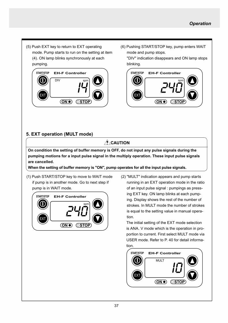

Operation
40
EXT
EH-F ControllerSTARTSTOP
ON STOP
ANA V
(5) Push EXT key to confirm the desired EXT mode Pump displays the EXT mode selection The picture below shows DIV appears to indi-cate DIV mode is selected
EXT
EH-F ControllerSTARTSTOP
ON STOP
DIV
EXT
EH-F ControllerSTARTSTOP
ON STOP
SET
EXT
EH-F ControllerSTARTSTOP
ON STOP
spm
EXT
EH-F ControllerSTARTSTOP
ON STOP
spm
EXT
EH-F ControllerSTARTSTOP
ON STOP
SET
7 USER settingThe setting of each function is changed in USER mode Have the pump entering WAIT mode in order to move to USER mode OUT (Output) is synchronous with spm and it can not be changed
7-1 EXT mode selection Any one of DIV (pulse dividing) MULT (pulse multiply) ANAR (analog rigid) or ANAV (analog vari-able) can be active in EXT mode The initial mode when shipped from factory is ANAV
(1) Push STARTSTOP key to move to WAIT mode if it is in another mode If it is in WAIT mode go to next step
(2) Press EXT key for more than 3 seconds to move to USER mode The picture below shows pump enters the EXT mode selection
(3) Pushing EXT key SET appears and display shows the mode currently set Picture below shows ANA V mode is selected
(4) Push or key to select a desired EXT mode The picture below shows DIV mode is selected
(6) Push STARTSTOP key to move to WAIT mode spm appears while DIV goes out
Operation
41
EXT
EH-F ControllerSTARTSTOP
ON STOP
spm
EXT
EH-F ControllerSTARTSTOP
ON STOP
ANA V
EXT
EH-F ControllerSTARTSTOP
ON STOP
SET
(3) Push key once
EXT
EH-F ControllerSTARTSTOP
ON STOP
(4) Push key again to move to the anti-chatter-ing setting display
EXT
EH-F ControllerSTARTSTOP
ON STOP
(5) Pushing EXT key display shows the mode cur-rently set and SET appears on it The picture below shows when MECH is selected
EXT
EH-F ControllerSTARTSTOP
ON STOP
SET
7-2 Setting of anti-chattering Anti-chattering function is settable against the incoming pulses during the DIV or MULT operation For the long chattering of mechanical contact such as relay set a large figure via MECH For the high speed (high frequency) chattering of the semi-conductor type contact such as transistor set a small figure via ELEC ST05 of MECH is initial setting
(6) Select MECH by or key for a mechani-cal contact And select ELEC for a semi-conductor contact The picture below shows ELEC is selected
(1) Push STARTSTOP key to move to WAIT mode if it is in another mode If it is in WAIT mode go to next step
(2) Press EXT key for more than 3 seconds to move to USER mode The picture below shows pump enters the EXT mode selection
Operation
42
EXT
EH-F ControllerSTARTSTOP
ON STOP
SET
(7) Push EXT key to display the current set state The picture below shows FT01 is selected
EXT
EH-F ControllerSTARTSTOP
ON STOP
SET EXT
EH-F ControllerSTARTSTOP
ON STOP
EXT
EH-F ControllerSTARTSTOP
ON STOP
spm
7-3 Setting of buffer memoryIn case pump operation can not catch up with the input pulse signals in DIV or MULT operation exces-sive pulse signals can be put in memory up to 65535 pulses However the excessive pulses can not be restored if once power is off or mode is changed
EXT
EH-F ControllerSTARTSTOP
ON STOP
spm
(2) Press EXT key for 3 seconds or more to move to USER mode The picture below shows the EXT mode selection display
EXT
EH-F ControllerSTARTSTOP
ON STOP
ANA V
(8) Set a large figure for the long chattering by or key and set a small figure for high speed (high frequency) chattering The picture below shows FT04 is selected
(9) Push EXT key to return to the anti-chattering setting display SET indication disappears
(10) Push STARTSTOP key to return to wait mode spm indication appears
(1) Push STARTSTOP key to move to WAIT mode if it is in another mode If it is in WAIT mode go to next
Operation
43
(3) Push key once
EXT
EH-F ControllerSTARTSTOP
ON STOP
(7) Push or key in order to set buffer memo-ry to ON or OFF Select MEM-Y to set it ON Select MEM-N for OFF setting The picture below shows when ON is set
EXT
EH-F ControllerSTARTSTOP
ON STOP
SET
(4) Push key once again
EXT
EH-F ControllerSTARTSTOP
ON STOP
(8) Push EXT key to return to the buffer memory setting display SET indication disappears
EXT
EH-F ControllerSTARTSTOP
ON STOP
(9) Push STARTSTOP key to return to WAIT mode spm indication appears
EXT
EH-F ControllerSTARTSTOP
ON STOP
spm
(5) Push key once again and the buffer memory setting display is shown
EXT
EH-F ControllerSTARTSTOP
ON STOP
(6) Push EXT key in order to display the current set state SET indication appears The picture below shows the buffer memory is set to OFF
EXT
EH-F ControllerSTARTSTOP
ON STOP
SET
Operation
44
8 Bleeding amp self-primingAt WAIT mode Manual operating mode and EXT operating mode pump operates at max speed tak-ing priority over any functions when both and keys are pushed at once Pump runs at max speed only when both keys are depressed Pump state returns to the previous mode once either or key is released Pressing and keys for 10 seconds keeps pump running at maximum speed In this state this fixation is released when pushing either or key once and pump returns to the previous mode
(1) When pump is running in ANAV mode
EXT
EH-F ControllerSTARTSTOP
ON STOP
ANA V spm
(2) Pump start to run at full speed when and keys are pressed at once Display shows
PRIME If either or key is released pump returns to the previous mode In this case pump returns to ANAV mode
EXT
EH-F ControllerSTARTSTOP
ON STOP
ANA V
(3) Pressing both and keys simultaneously for 10 seconds or more pump continues to run at full speed even if both keys are released In this case indication appearsPush either or key to release this state indication disappears and pump returns to the previous mode In this case pump returns to ANAV mode
EXT
EH-F ControllerSTARTSTOP
ON STOP
ANA V
Operation
45
10 Error display and release(1) In case Input signals fall to 4 mA or below while
4-20 or 20-4 is set to ANA R mode pump stops with DISCN blinking and Err on dis-play
(2) This error state can be released by push-ing STARTSTOP key and pumps enters wait mode In this case check the wiring and input signals
EXT
EH-F ControllerSTARTSTOP
ON STOP
ANAR
Err
spm
EXT
EH-F ControllerSTARTSTOP
ON STOP
spm
9 Key lockKey lock function is to prevent pump from being operated by some other person than user If STARTSTOP key is pressed for five seconds or more when pump is running or stops all key operations become ineffective with LOCK indication on display This function can be released by pressing STARTSTOP key for 5 seconds while LOCK lights
EXT
EH-F ControllerSTARTSTOP
ON STOP
MAN spm
LOCK
46
Do not conduct a maintenance work with the wet hands It can cause an electric shock
Before dismantling pump be sure to turn off power and check the pump is not electrified Do not
start a dismantlement work after stopping the pump by pushing the STARTSTOP key only Put up
the sign of ldquoMaintenance work is in progressrdquo in order to prevent a pump switch from turning on
unintentionally during the work Release the pressure of discharge piping and drain the liquid from
the wet end parts And then clean the inside of pump head
Wear protective clothing such as a protective mask globes goggles and chemical-proof wear
according to the handled chemical liquid during the work
WARNING
5 Maintenance
1 Trouble shootingTrouble Cause Troubleshooting
Pump dose not start Faulty wiring or disconnection in wiring Voltage is too low Failure in the electronic circuit of control unit
Pump dose not suck liquidDischarge amount is low
Air suction from suction piping Valve gasket is not installed Valve set assembling direction is wrong Pump is air-locked Pump stroke length is too short Suction-sidedischarge-side valve is clogged with
foreign matter Adhesion of valve onto valve seat
Discharge amount fluctuates
Liquid leaks
Key operation is ineffective Key is locked Release key lock
Pump doesnt run
Pump is in waiting mode Signals are not coming for EXT operation Pump is in EXT setting mode Pump is suspended with STOP
Move to operation mode Check wiring and correct the wrong part Move to EXT operating mode Release STOP function
Abnormal noise
Suction-sidedischarge-side valve is clogged with foreign matters
The sound absorption gasket is worn out Bearing is worn out Spring is damaged
Piping vibrates due to pulsation Bearing is worn out Spring is damaged
Install a accumulator or an air chamber The end of pump life span The end of pump life span
Suction-sidedischarge-side valve is clogged with foreign matters
Air is trapped in pump Overfeeding Diaphragm is damaged
Fittings are not tightly closed Pump head is not tightened Diaphragm is damaged O ring and valve gasket are not installed O ring is damaged
Correct wiring Inspect power source and provide measurement Replace the whole unit
Arrange piping again Install valve gasket Reassemble valve set Carry out air elimination Drive pump with 100 stroke length to prime liquid Then
reset stroke length Disassemble inspect and clean Disassemble inspect and clean
Tighten fittings Tighten pump head Replace diaphragm Install O ring and valve gasket Replace O ring
Disassemble inspect and clean
Carry out air elimination Install a check valve or a back pressure valve Replace diaphragm
Disassemble inspect and clean
The end of pump life span The end of pump life span The end of pump life span
Abnormal vibration
Input pulse can not be read Signals are not coming Anti-chattering setting is not proper
Check wiring and correct the wrong part Change the setting properly
Analog signal input can not be read
Wrong wiring Signals are over acceptable loaded resistance
Check wiring and correct wrong part The load resistance is 200Ω Use some devise which can
accept the load resistance
47
CAUTION Check periodically whether the bolts fixing pump head are tightened Tighten them as needed
The bolts fixing pump head may loosen in operation Tightening torque 255Nbullm
Maintenance
3
bull Tighten joint where leakage has occurredbull The excessive air bubbles in the discharged liquid mean air suc-
tion has been caused in system Examine the piping and tighten joint on where leaks
Is there liquid leakage or air suction at any joints on pump or piping
2 Maintenance and inspection
1 Daily inspectionPay attention to the following points during pump operation Stop pump immediately upon detecting abnormality and take measures according to the item Troubleshooting When wear parts come to the life time replace them by new ones
No
1
2
Check Point Description
Does pump lift liquid normally
bull Is liquid normally fedbull Is suction pressuredischarge pressure at normal levelbull Has liquid undergone quality change crystallization or solidifica-
tion
Abnormal noise or vibrationbull Abnormal noise or vibration may happen from the abnormal func-
tioning of pump
EXT setting can not be stored
After EXT setting STARTSTOP key is pushed for EXT by mistake
Push EXT key to operate pump in EXT mode
ldquoPRIME is kept indicated and other operations are inac-cessible
Self-priming function is active Push either or key to release the function
Analog signal input can not be read and DISCN indication appears
Wrong wiring or disconnection Check wiring and correct the wrong part Refer to page 45
for how to release an error indication
Trouble Cause Troubleshooting
48
Maintenance
2 Wear partsWear parts should be replaced in proper period for a long period of pump operation It is recommended that follow-ing parts are always ready for the replacementVC V6 PC P6 types
Parts Qty Life span
Pum
p he
ad
Valve set
EH-F35 EH-F45 EH-F55middot70
2sets
8000hours
Diaphragm 1
Refer to exploded view
Bac
k pr
essu
re v
alve
1
2
Che
ck v
alve
7 6 1
8 11 1
Diaphragm seat 1
O ring
Poppet check valve (With check gasket)
Check valve spring Spacer
Diaphragm
O ring
Note Durability of wear parts depend on the pumped liquid temperature and pressure Time to be replaced mentioned as above is the estimation obtained by continuous pump-ing of clean water at ambient temperature
8000hours
4000hours
49
3 Dismantlement and assembly
Getting wet with or coming in contact with chemicals and toxic liquid is harmful Wear protective clothing such as a protective mask globes goggles and chemical-proof wear during the work
Risk of electrical shock Be sure to turn off power and confirm that pump and devices are not electrified before the work
Release the pressure inside pump and a discharge hose by opening an air bleed valve on piping prior to loosening the piping connections or the dismantlement of pump Dismantlement with the pressure inside pump could lead to liquid spillage
Be careful not to touch residual liquid when dismantling pump Some liquids are harmful for skin or component parts Wipe off liquid when the hand or the component parts come in contact with liquid
WARNING
CAUT ION
Hose
Hose stopperFitting spacer
O ring
Fitting nut
Fitting
Pumphead
Remove the fittingwith a spanner
1 Valve set replacement Dismantlement1 Loosen a fitting nut and remove the hose con-
nected to pump head Pay attention to the liquid dripping
2 Loosen a fitting with a spanner to remove it Then detach the valve set from pump head
Maintenance
50
AssemblyAssembly procedure is in reverse order to disas-sembly Pay attention to the following when assembling valve set DispositionInsertion direction of valve set The wrong dispositioninsertion direction of valve
set component can lead to leakage and less dis-charge amount
O ring is fitted properly1 Discharge side valve set mounting
Put valve set in pump head and screw a fitting into a pump head by hand and then re-tighten it by 14 turns with a spanner
2 Suction side valve set mountingPut valve set in connection port and screw the fitting into pump head by hand and then re-tighten it by 14 turns with spanner
Note Pay attention to the mounting direction of the spacer fitted to EH-F45(VC V6 PC)Make sure the cut portion on the spacer of suction side should be downward the one of discharge side should be upward
Suction side
Discharge side
O ringValve gasket
Valve gasket
Valve gasket
Valve guideValveValve seatSpacer
O ring
Valve gasketValve guideValveValve seat
Spacer
1714
11
1312
11
1312
17
17
14
14
14
11
31
1312
31
17
14
11
1312
12
13
11
14
EH-F35
EH-F45
EH-F5570
Suct
ion
side
Dis
char
ge s
ide
For b
oth
suct
ion
and
disc
harg
e si
deFo
r bot
h su
ctio
nan
d di
scha
rge
side
VC V6 PC P6 Type
Maintenance
51
Pay attention not to lose diaphragm spacer and to apply the correct number of diaphragm spacers 0 to several pieces of diaphragm spacers are put between retainer and plunger to adjust the position of diaphragm The number of spacers mounted depends on the pump model There are the models which do not have spacers
Maintenance
2 Diaphragm replacement Dismantlement1 Set stroke length to 0 by adjusting stroke length
adjustment knob
2 Remove the pump head from the pump body by loos-ening hex socket cap bolts
3 Rotate a diaphragm anti-clockwise to remove it from a plunger pin The diaphragm is screwed into the plunger pin
AssemblyAssembly is done in reverse order to disassembly Follow the steps below1 Make sure the stroke length of pump is set to 0
prior to an assembly Operate pump to set the stroke length to 0 and
stop it Then turn off power
2 Fit a rear diaphragm seat a retainer and a diaphragm spacer into new diaphragm via the threaded pin and screw the diaphragm into the plunger pin
Fit the concave side of retainer into the convex side of diaphragm Pay attention the retainer dose not come off
3 Set the stroke length to 100 Operate pump to set the stroke length to 100
and stop it Then turn off power4 Install a pump head to a pump body by tightening
the hex sock cap bolts equally Tightening torque is 255Nbullm
52
4 Accessories1 Connection port bore bull Check valve bull Back pressure valve
Note1 Check valves and back pressure valves are options2 Regarding the connection of the discharge side of back pressure valve
NPT38 and NPT12 taper pipe thread is used for BV-N-CR
Pump type Connection port bore Check valve Back pressure valve
EH-F35VC empty38timesempty12 hose CA-3VCH-C6 ndash
empty38timesempty12 hose CA-3VEH-C6 ndashempty38timesempty12 hose CA-3VH-C6 ndashempty38timesempty12 hose CA-3VCH-C6 ndashempty38timesempty12 hose CA-3VEH-C6 ndashempty38timesempty12 hose CA-3VH-C6 ndash
V6
empty38timesempty12 hose ndash BV-3NV-C6Rempty38timesempty12 hose ndash BV-3NE-C6Rempty38timesempty12 hose ndash BV-3NPV-C6Rempty58timesempty34 hose ndash BV-3NV-C7Rempty58timesempty34 hose ndash BV-3NE-C7Rempty58timesempty34 hose ndash BV-3NPV-C7R
PC
EH-F45VCV6PC
EH-F55VCV6PC
EH-F70VCV6PC
Maintenance
53
Maintenance
5 Exploded view
1 General view The extent of dismantlement is within the following exploded view
Diaphragm spacer
Retainer
(Back up retainer)55 bull 70 types
Pump body
Valve set
Valve set
Pump head
Diaphragm
Rear diaphragm sheet
54
2 Pump head (Hose connection type)
EH-F45 type EH-F35 type
4
28
2930
3
1114
131211
131217
1897
1
17
111312111312
3
3029
28
4
1920
1920 21
17
111312
31
3
3029
28
4
131217
189
7
11
3114
14
4
282930
3
1
21
1515
EH-F55 type
4
28
2930
3
11
131217
18
9
7
10
1
1920 21
17
111312
3
30
29
28
4
EH-F70 type
4
28
2930
3
14
11131217
18
9
7
10
1
1920 21 17
111312
3
30
29
28
4
15 15
14
1414
14
14 14
Note1 The back up retainer of No10 is only for EH-F55 bull 70 typesNote2 The figure inside ( ) in the above table is for EH-F45 bull 55 bull 70 typesNote3 The number of the diaphragm spacers (No18) is not constant None or a few spacers is inserted at
each diaphragmNote4 The figure inside ( ) in the above table is for EH-F70Note5 EH-F35 bull 55 bull 70 (VC V6 PC ) types require 2 valve gaskets and EH-F45 (VC V6 PC) types
require 4 of themNote6 The spacer on No31 is for EH-F45 type only
No Name Qty1 Pump head 13 Fitting 24 Fitting nut 27 Diaphragm 19 Retainer 110 Back up retainer 1 Note111 Valve guide 4 (2) Note212 Valve seat13 Valve14 Valve gasket
No Name Qty
17 O ring 218 Diaphragm spacer 1 Note319 Hex socket head bolt 6 (8) Note420 Spring washer21 Plain washer28 Hose stopper 229 Fitting spacer 230 O ring 231 Spacer 2 Note6
15 Rear diaphragm seat 1
2 (4) Note54 (2) Note24 (2) Note2
6 (8) Note46 (8) Note4
Maintenance
55
Maintenance
3 Pump head (Flange connection type) EH-F55 type
30
3
11
131217
18
9
7
10
1
1920 21
17
11
1312
3
30
EH-F70 type
15
EH-F45 type EH-F35 type
30
3
11131211
131217
1897
1
17
11131211
1312
3
30
1920
1920 21
17
111312
31
3
131217
189
7
11
31
30
3
1
30
21
1515
30
3
11131217
18
9
7
10
1
1920 21 17
11
1312
3
30
15
32
33
33
32
4
32
433
43332
32
334
43332
32
33
32
334
44
1414
14 14 14
1414
14
14 14
NoNo Name Qty1 Pump head 13 Fitting 24 Fitting nut 27 Diaphragm 19 Retainer 110 Back up retainer 1 Note111 Valve guide 4(2)Note212 Valve seat 4(2)Note213 Valve 4(2)Note214 Valve gasket 2(4)Note5
Name Qty
17 O ring 218 Diaphragm spacer 1 Note319 Hex socket cap bolt 6(8)Note420 Spring washer 6(8)Note421 Plain washer 6(8)Note430 O ring 2
33 Union 2
31 Spacer 2 Note6
15 Rear diaphragm seat 1
32 Flange 2
Note1 The back up retainer of No10 is only for EH-F55 bull 70 typesNote2 The figure inside ( ) in the above table is for EH-F45 bull 55 bull 70 typesNote3 The number of the diaphragm spacers (No18) is not constant None or a few spacers is inserted at
each diaphragmNote4 The figure inside ( ) in the above table is for EH-F70Note5 EH-F35 bull 55 bull 70 (VC V6 ) types require 2 valve gaskets and EH-F45 (VC V6) types require 4 of
themNote6 The spacer on No31 is for EH-F45 type only
56
4 Pump head (Flange connection horizontal suction port type) EH-F55 type
30
3
11
131217
18
9
7
10
1
1920 21
17
111312
3
30
EH-F70 Type
15
EH-F45 Type EH-F35 type
30
3
11131211
131217
1897
1
17
111312111312
3
30
1920
1920 21
17
11131231
3
131217
189
7
11
31
30
3
1
30
21
1515
30
3
11131217
18
9
7
10
1
1920 21 17
111312
3
30
15
32
33
32
433
43334
32
32
334
43334
32
33
44
34
32
334
34
32
334
32
35 353535
1414
14 14 14
1414
14
14 14
No Name Qty1 Pump head 13 Fitting 24 Fitting nut 27 Diaphragm 19 Retainer 110 Back up retainer 1 Note111 Valve guide 4 (2) Note212 Valve seat13 Valve
15 Rear diaphragm sheet 114 Valve gasket
No Name Qty
18 Diaphragm spacer 1 Note319 Hex socket cap bolt20 Spring washer21 Plain washer
31 Spacer 2 Note6
35 Pipe 1
32 Flange 2
34 Elbow 133 Union 2
17 O ring 2
30 O ring 2
4 (2) Note24 (2) Note22 (4) Note5
6 (8) Note4
4 (2) Note24 (2) Note2
Maintenance
Note1 The back up retainer of No10 is only for EH-F55 bull 70 typesNote2 The figure inside ( ) in the above table is for EH-F45 bull 55 bull 70 typesNote3 The number of the diaphragm spacers (No18) is not constant None or a few spacers is inserted at
each diaphragmNote4 The figure inside ( ) in the above table is for EH-F70Note5 EH-F35 bull 55 bull 70 (VC V6) types require 2 valve gaskets and EH-F45 (VC V6) types require 4 of
themNote6 The spacer on No31 is for EH-F45 type only
57
5 Check valve CA-3 type
1 2 3 4 5 6 7 8 11 9 10
16
14
13
15
12
3
15
17
16
1110
98
7
1
54
2
6
14
13
6 Back pressure valve BV-3N-R type
No No Name Qty10 Stopper 111 Diaphragm 112 Lower case 113 Fitting spacer Hose port 114 Hose stopper Ferrule 115 O ring 216 Nut 217 Fitting 1
Name Qty1 Upper case 12 Hexhead bolt (with PW SW) 43 Hex nut 44 Adjusting bolt 15 Hexnut 16 Plain washer 1
8 Spring 19 Retainer plate 1
7 Spring seat 1
NoNo Name Qty1 Fitting nut 12 Hose stopper 13 Fitting spacer 14 O ring 15 Valve case 16 Gasket 1
Name Qty7 Poppet valve 18 Spring 19 O ring 110 Valve fitting 111 Spacer 1
Maintenance
58
Maintenance
1 Outer dimension (Hose connection type) EH-F35 type
TUBING(38rdquotimes12rdquo)
38rdquotimes12rdquo
EH-F45 type
38rdquotimes12rdquo
38rdquotimes12rdquo
59
EH-F55 type
58rdquotimes34rdquo
58rdquotimes34rdquo
EH-F70 type
Maintenance
38rdquotimes12rdquo
38rdquotimes12rdquo
60
Maintenance
2 Outer dimension (Flange connection type) EH-F35 type
EH-F45 type
61
EH-F55 type
EH-F70 type
Maintenance
62
Maintenance
3 Outer dimension (Flange connection horizontal suction port type) EH-F35 type
EH-F45 type
63
EH-F55 type
EH-F70Type
Maintenance
httpwwwiwakipumpsjp
Read this manual before use of product
IWAKIElectromagnetic Metering Pump
EH-F series (North America)
Instruction ManualT596 0706
GermanyItalyDenmarkSwedenFinlandNorwayFranceUKSwitzerlandAustriaHollandSpainBelgiumUSA
TEL (49)2154 9254 0TEL (39)02 990 3931TEL (45)48 24 2345TEL (46)8 511 72900TEL (358)9 2742714TEL (47)66 81 16 60TEL (33)1 69 63 33 70TEL (44)1743 231363TEL (41)26 674 9300TEL (43)2236 33469TEL (31)297 241121TEL (34)943 630030TEL (32)1367 0200TEL (1)508 429 1440
AustraliaSingaporeIndonesiaMalaysiaTaiwanThailandHong KongChinaChinaChinaChinaPhilippinesKoreaVietnam
TEL (61)2 9899 2411TEL (65)6316 2028TEL (62)21 690 6606TEL (60)3 7803 8807TEL (886)2 8227 6900TEL (66)2 322 2471TEL (852)2 607 1168TEL (86)750 380 9018TEL (86)20 8435 0603TEL (86)10 6442 7713TEL (86)21 6272 7502TEL (63)2 888 0245TEL (82)2 3474 0523TEL (84)613 933456
IWAKI EUROPE GmbH IWAKI Italia SRL IWAKI Nordic AS IWAKI Sverige AB IWAKI Suomi Oy IWAKI Norge AS IWAKI France SA IWAKI PUMPS (UK) LTD IWAKI (Schweiz) AG IWAKI (Austria) GmbH IWAKI Holland BV IWAKI Iberica Pumps SA IWAKI Belgium nv IWAKI America Incorporated
FAX 2154 1028FAX 02 990 42888FAX 48 24 2346FAX 8 511 72922FAX 9 2742715FAX 66 81 16 61FAX 1 64 49 92 73FAX 1743 366507FAX 26 674 9302FAX 2236 33469FAX 297 273902FAX 943 628799FAX 1367 2030FAX 508 429 1386
IWAKI Pumps Australia Pty Ltd IWAKI Singapore Pte Ltd IWAKI Singapore (Indonesia Branch) IWAKIm Sdn Bhd IWAKI Pumps Taiwan Co Ltd IWAKI (Thailand) CoLtd IWAKI Pumps Co Ltd IWAKI Pumps (Guandong) Co Ltd GFTZ IWAKI Engineering amp Trading (Guangzhou) IWAKI Pumps Co Ltd (Beijing) IWAKI Pumps (Shanghai) Co Ltd IWAKI Chemical Pumps Philippines Inc IWAKI Korea CoLtd IWAKI Pumps Vietnam Joint Venture CoLtd
FAX 2 9899 2421FAX 6316 3221FAX 21 690 6612FAX 3 7803 4800FAX 2 8227 6818FAX 2 322 2477FAX 2 607 1000FAX 750 380 9078FAX 20 8435 9181FAX 10 6442 7712FAX 21 6272 6929FAX 2 843 3096FAX 2 3474 0221FAX 613 933399
( )Country codes
IWAKI COLTD 6-6 Kanda-Sudacho 2-chome Chiyoda-ku Tokyo 101-8558 JapanTEL(81)3 3254 2935 FAX3 3252 8892(httpwwwiwakipumpsjp)
This is patent pending product
- 107
- 47
- 48
- 49
- 50
- 3
- 4
- 64
- 102
- 101
- 78
- 79
- 91
- 81
- 100
- 99
- 84
- 86
- 85
- 87
- 22
- 23
- 73
- 72
- 26
- 98
- 28
- 27
- 31
- 32
- 29
- 30
- 95
- 34
- 33
- 96
- 35
- 36
- 37
- 38
- 40
- 39
- 41
- 42
- 59
- 58
- 45
- 7
- 6
- 46
- 5
- 8
- 9
- 74
- 75
- 10
- 11
- 61
- 60
- 15
- 14
- 62
- 63
- 16
- 17
- 18
- 19
- 92
- 94
- 93
- 103
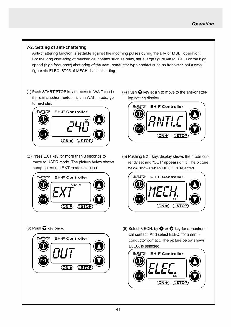
Operation
43
(3) Push key once
EXT
EH-F ControllerSTARTSTOP
ON STOP
(7) Push or key in order to set buffer memo-ry to ON or OFF Select MEM-Y to set it ON Select MEM-N for OFF setting The picture below shows when ON is set
EXT
EH-F ControllerSTARTSTOP
ON STOP
SET
(4) Push key once again
EXT
EH-F ControllerSTARTSTOP
ON STOP
(8) Push EXT key to return to the buffer memory setting display SET indication disappears
EXT
EH-F ControllerSTARTSTOP
ON STOP
(9) Push STARTSTOP key to return to WAIT mode spm indication appears
EXT
EH-F ControllerSTARTSTOP
ON STOP
spm
(5) Push key once again and the buffer memory setting display is shown
EXT
EH-F ControllerSTARTSTOP
ON STOP
(6) Push EXT key in order to display the current set state SET indication appears The picture below shows the buffer memory is set to OFF
EXT
EH-F ControllerSTARTSTOP
ON STOP
SET
Operation
44
8 Bleeding amp self-primingAt WAIT mode Manual operating mode and EXT operating mode pump operates at max speed tak-ing priority over any functions when both and keys are pushed at once Pump runs at max speed only when both keys are depressed Pump state returns to the previous mode once either or key is released Pressing and keys for 10 seconds keeps pump running at maximum speed In this state this fixation is released when pushing either or key once and pump returns to the previous mode
(1) When pump is running in ANAV mode
EXT
EH-F ControllerSTARTSTOP
ON STOP
ANA V spm
(2) Pump start to run at full speed when and keys are pressed at once Display shows
PRIME If either or key is released pump returns to the previous mode In this case pump returns to ANAV mode
EXT
EH-F ControllerSTARTSTOP
ON STOP
ANA V
(3) Pressing both and keys simultaneously for 10 seconds or more pump continues to run at full speed even if both keys are released In this case indication appearsPush either or key to release this state indication disappears and pump returns to the previous mode In this case pump returns to ANAV mode
EXT
EH-F ControllerSTARTSTOP
ON STOP
ANA V
Operation
45
10 Error display and release(1) In case Input signals fall to 4 mA or below while
4-20 or 20-4 is set to ANA R mode pump stops with DISCN blinking and Err on dis-play
(2) This error state can be released by push-ing STARTSTOP key and pumps enters wait mode In this case check the wiring and input signals
EXT
EH-F ControllerSTARTSTOP
ON STOP
ANAR
Err
spm
EXT
EH-F ControllerSTARTSTOP
ON STOP
spm
9 Key lockKey lock function is to prevent pump from being operated by some other person than user If STARTSTOP key is pressed for five seconds or more when pump is running or stops all key operations become ineffective with LOCK indication on display This function can be released by pressing STARTSTOP key for 5 seconds while LOCK lights
EXT
EH-F ControllerSTARTSTOP
ON STOP
MAN spm
LOCK
46
Do not conduct a maintenance work with the wet hands It can cause an electric shock
Before dismantling pump be sure to turn off power and check the pump is not electrified Do not
start a dismantlement work after stopping the pump by pushing the STARTSTOP key only Put up
the sign of ldquoMaintenance work is in progressrdquo in order to prevent a pump switch from turning on
unintentionally during the work Release the pressure of discharge piping and drain the liquid from
the wet end parts And then clean the inside of pump head
Wear protective clothing such as a protective mask globes goggles and chemical-proof wear
according to the handled chemical liquid during the work
WARNING
5 Maintenance
1 Trouble shootingTrouble Cause Troubleshooting
Pump dose not start Faulty wiring or disconnection in wiring Voltage is too low Failure in the electronic circuit of control unit
Pump dose not suck liquidDischarge amount is low
Air suction from suction piping Valve gasket is not installed Valve set assembling direction is wrong Pump is air-locked Pump stroke length is too short Suction-sidedischarge-side valve is clogged with
foreign matter Adhesion of valve onto valve seat
Discharge amount fluctuates
Liquid leaks
Key operation is ineffective Key is locked Release key lock
Pump doesnt run
Pump is in waiting mode Signals are not coming for EXT operation Pump is in EXT setting mode Pump is suspended with STOP
Move to operation mode Check wiring and correct the wrong part Move to EXT operating mode Release STOP function
Abnormal noise
Suction-sidedischarge-side valve is clogged with foreign matters
The sound absorption gasket is worn out Bearing is worn out Spring is damaged
Piping vibrates due to pulsation Bearing is worn out Spring is damaged
Install a accumulator or an air chamber The end of pump life span The end of pump life span
Suction-sidedischarge-side valve is clogged with foreign matters
Air is trapped in pump Overfeeding Diaphragm is damaged
Fittings are not tightly closed Pump head is not tightened Diaphragm is damaged O ring and valve gasket are not installed O ring is damaged
Correct wiring Inspect power source and provide measurement Replace the whole unit
Arrange piping again Install valve gasket Reassemble valve set Carry out air elimination Drive pump with 100 stroke length to prime liquid Then
reset stroke length Disassemble inspect and clean Disassemble inspect and clean
Tighten fittings Tighten pump head Replace diaphragm Install O ring and valve gasket Replace O ring
Disassemble inspect and clean
Carry out air elimination Install a check valve or a back pressure valve Replace diaphragm
Disassemble inspect and clean
The end of pump life span The end of pump life span The end of pump life span
Abnormal vibration
Input pulse can not be read Signals are not coming Anti-chattering setting is not proper
Check wiring and correct the wrong part Change the setting properly
Analog signal input can not be read
Wrong wiring Signals are over acceptable loaded resistance
Check wiring and correct wrong part The load resistance is 200Ω Use some devise which can
accept the load resistance
47
CAUTION Check periodically whether the bolts fixing pump head are tightened Tighten them as needed
The bolts fixing pump head may loosen in operation Tightening torque 255Nbullm
Maintenance
3
bull Tighten joint where leakage has occurredbull The excessive air bubbles in the discharged liquid mean air suc-
tion has been caused in system Examine the piping and tighten joint on where leaks
Is there liquid leakage or air suction at any joints on pump or piping
2 Maintenance and inspection
1 Daily inspectionPay attention to the following points during pump operation Stop pump immediately upon detecting abnormality and take measures according to the item Troubleshooting When wear parts come to the life time replace them by new ones
No
1
2
Check Point Description
Does pump lift liquid normally
bull Is liquid normally fedbull Is suction pressuredischarge pressure at normal levelbull Has liquid undergone quality change crystallization or solidifica-
tion
Abnormal noise or vibrationbull Abnormal noise or vibration may happen from the abnormal func-
tioning of pump
EXT setting can not be stored
After EXT setting STARTSTOP key is pushed for EXT by mistake
Push EXT key to operate pump in EXT mode
ldquoPRIME is kept indicated and other operations are inac-cessible
Self-priming function is active Push either or key to release the function
Analog signal input can not be read and DISCN indication appears
Wrong wiring or disconnection Check wiring and correct the wrong part Refer to page 45
for how to release an error indication
Trouble Cause Troubleshooting
48
Maintenance
2 Wear partsWear parts should be replaced in proper period for a long period of pump operation It is recommended that follow-ing parts are always ready for the replacementVC V6 PC P6 types
Parts Qty Life span
Pum
p he
ad
Valve set
EH-F35 EH-F45 EH-F55middot70
2sets
8000hours
Diaphragm 1
Refer to exploded view
Bac
k pr
essu
re v
alve
1
2
Che
ck v
alve
7 6 1
8 11 1
Diaphragm seat 1
O ring
Poppet check valve (With check gasket)
Check valve spring Spacer
Diaphragm
O ring
Note Durability of wear parts depend on the pumped liquid temperature and pressure Time to be replaced mentioned as above is the estimation obtained by continuous pump-ing of clean water at ambient temperature
8000hours
4000hours
49
3 Dismantlement and assembly
Getting wet with or coming in contact with chemicals and toxic liquid is harmful Wear protective clothing such as a protective mask globes goggles and chemical-proof wear during the work
Risk of electrical shock Be sure to turn off power and confirm that pump and devices are not electrified before the work
Release the pressure inside pump and a discharge hose by opening an air bleed valve on piping prior to loosening the piping connections or the dismantlement of pump Dismantlement with the pressure inside pump could lead to liquid spillage
Be careful not to touch residual liquid when dismantling pump Some liquids are harmful for skin or component parts Wipe off liquid when the hand or the component parts come in contact with liquid
WARNING
CAUT ION
Hose
Hose stopperFitting spacer
O ring
Fitting nut
Fitting
Pumphead
Remove the fittingwith a spanner
1 Valve set replacement Dismantlement1 Loosen a fitting nut and remove the hose con-
nected to pump head Pay attention to the liquid dripping
2 Loosen a fitting with a spanner to remove it Then detach the valve set from pump head
Maintenance
50
AssemblyAssembly procedure is in reverse order to disas-sembly Pay attention to the following when assembling valve set DispositionInsertion direction of valve set The wrong dispositioninsertion direction of valve
set component can lead to leakage and less dis-charge amount
O ring is fitted properly1 Discharge side valve set mounting
Put valve set in pump head and screw a fitting into a pump head by hand and then re-tighten it by 14 turns with a spanner
2 Suction side valve set mountingPut valve set in connection port and screw the fitting into pump head by hand and then re-tighten it by 14 turns with spanner
Note Pay attention to the mounting direction of the spacer fitted to EH-F45(VC V6 PC)Make sure the cut portion on the spacer of suction side should be downward the one of discharge side should be upward
Suction side
Discharge side
O ringValve gasket
Valve gasket
Valve gasket
Valve guideValveValve seatSpacer
O ring
Valve gasketValve guideValveValve seat
Spacer
1714
11
1312
11
1312
17
17
14
14
14
11
31
1312
31
17
14
11
1312
12
13
11
14
EH-F35
EH-F45
EH-F5570
Suct
ion
side
Dis
char
ge s
ide
For b
oth
suct
ion
and
disc
harg
e si
deFo
r bot
h su
ctio
nan
d di
scha
rge
side
VC V6 PC P6 Type
Maintenance
51
Pay attention not to lose diaphragm spacer and to apply the correct number of diaphragm spacers 0 to several pieces of diaphragm spacers are put between retainer and plunger to adjust the position of diaphragm The number of spacers mounted depends on the pump model There are the models which do not have spacers
Maintenance
2 Diaphragm replacement Dismantlement1 Set stroke length to 0 by adjusting stroke length
adjustment knob
2 Remove the pump head from the pump body by loos-ening hex socket cap bolts
3 Rotate a diaphragm anti-clockwise to remove it from a plunger pin The diaphragm is screwed into the plunger pin
AssemblyAssembly is done in reverse order to disassembly Follow the steps below1 Make sure the stroke length of pump is set to 0
prior to an assembly Operate pump to set the stroke length to 0 and
stop it Then turn off power
2 Fit a rear diaphragm seat a retainer and a diaphragm spacer into new diaphragm via the threaded pin and screw the diaphragm into the plunger pin
Fit the concave side of retainer into the convex side of diaphragm Pay attention the retainer dose not come off
3 Set the stroke length to 100 Operate pump to set the stroke length to 100
and stop it Then turn off power4 Install a pump head to a pump body by tightening
the hex sock cap bolts equally Tightening torque is 255Nbullm
52
4 Accessories1 Connection port bore bull Check valve bull Back pressure valve
Note1 Check valves and back pressure valves are options2 Regarding the connection of the discharge side of back pressure valve
NPT38 and NPT12 taper pipe thread is used for BV-N-CR
Pump type Connection port bore Check valve Back pressure valve
EH-F35VC empty38timesempty12 hose CA-3VCH-C6 ndash
empty38timesempty12 hose CA-3VEH-C6 ndashempty38timesempty12 hose CA-3VH-C6 ndashempty38timesempty12 hose CA-3VCH-C6 ndashempty38timesempty12 hose CA-3VEH-C6 ndashempty38timesempty12 hose CA-3VH-C6 ndash
V6
empty38timesempty12 hose ndash BV-3NV-C6Rempty38timesempty12 hose ndash BV-3NE-C6Rempty38timesempty12 hose ndash BV-3NPV-C6Rempty58timesempty34 hose ndash BV-3NV-C7Rempty58timesempty34 hose ndash BV-3NE-C7Rempty58timesempty34 hose ndash BV-3NPV-C7R
PC
EH-F45VCV6PC
EH-F55VCV6PC
EH-F70VCV6PC
Maintenance
53
Maintenance
5 Exploded view
1 General view The extent of dismantlement is within the following exploded view
Diaphragm spacer
Retainer
(Back up retainer)55 bull 70 types
Pump body
Valve set
Valve set
Pump head
Diaphragm
Rear diaphragm sheet
54
2 Pump head (Hose connection type)
EH-F45 type EH-F35 type
4
28
2930
3
1114
131211
131217
1897
1
17
111312111312
3
3029
28
4
1920
1920 21
17
111312
31
3
3029
28
4
131217
189
7
11
3114
14
4
282930
3
1
21
1515
EH-F55 type
4
28
2930
3
11
131217
18
9
7
10
1
1920 21
17
111312
3
30
29
28
4
EH-F70 type
4
28
2930
3
14
11131217
18
9
7
10
1
1920 21 17
111312
3
30
29
28
4
15 15
14
1414
14
14 14
Note1 The back up retainer of No10 is only for EH-F55 bull 70 typesNote2 The figure inside ( ) in the above table is for EH-F45 bull 55 bull 70 typesNote3 The number of the diaphragm spacers (No18) is not constant None or a few spacers is inserted at
each diaphragmNote4 The figure inside ( ) in the above table is for EH-F70Note5 EH-F35 bull 55 bull 70 (VC V6 PC ) types require 2 valve gaskets and EH-F45 (VC V6 PC) types
require 4 of themNote6 The spacer on No31 is for EH-F45 type only
No Name Qty1 Pump head 13 Fitting 24 Fitting nut 27 Diaphragm 19 Retainer 110 Back up retainer 1 Note111 Valve guide 4 (2) Note212 Valve seat13 Valve14 Valve gasket
No Name Qty
17 O ring 218 Diaphragm spacer 1 Note319 Hex socket head bolt 6 (8) Note420 Spring washer21 Plain washer28 Hose stopper 229 Fitting spacer 230 O ring 231 Spacer 2 Note6
15 Rear diaphragm seat 1
2 (4) Note54 (2) Note24 (2) Note2
6 (8) Note46 (8) Note4
Maintenance
55
Maintenance
3 Pump head (Flange connection type) EH-F55 type
30
3
11
131217
18
9
7
10
1
1920 21
17
11
1312
3
30
EH-F70 type
15
EH-F45 type EH-F35 type
30
3
11131211
131217
1897
1
17
11131211
1312
3
30
1920
1920 21
17
111312
31
3
131217
189
7
11
31
30
3
1
30
21
1515
30
3
11131217
18
9
7
10
1
1920 21 17
11
1312
3
30
15
32
33
33
32
4
32
433
43332
32
334
43332
32
33
32
334
44
1414
14 14 14
1414
14
14 14
NoNo Name Qty1 Pump head 13 Fitting 24 Fitting nut 27 Diaphragm 19 Retainer 110 Back up retainer 1 Note111 Valve guide 4(2)Note212 Valve seat 4(2)Note213 Valve 4(2)Note214 Valve gasket 2(4)Note5
Name Qty
17 O ring 218 Diaphragm spacer 1 Note319 Hex socket cap bolt 6(8)Note420 Spring washer 6(8)Note421 Plain washer 6(8)Note430 O ring 2
33 Union 2
31 Spacer 2 Note6
15 Rear diaphragm seat 1
32 Flange 2
Note1 The back up retainer of No10 is only for EH-F55 bull 70 typesNote2 The figure inside ( ) in the above table is for EH-F45 bull 55 bull 70 typesNote3 The number of the diaphragm spacers (No18) is not constant None or a few spacers is inserted at
each diaphragmNote4 The figure inside ( ) in the above table is for EH-F70Note5 EH-F35 bull 55 bull 70 (VC V6 ) types require 2 valve gaskets and EH-F45 (VC V6) types require 4 of
themNote6 The spacer on No31 is for EH-F45 type only
56
4 Pump head (Flange connection horizontal suction port type) EH-F55 type
30
3
11
131217
18
9
7
10
1
1920 21
17
111312
3
30
EH-F70 Type
15
EH-F45 Type EH-F35 type
30
3
11131211
131217
1897
1
17
111312111312
3
30
1920
1920 21
17
11131231
3
131217
189
7
11
31
30
3
1
30
21
1515
30
3
11131217
18
9
7
10
1
1920 21 17
111312
3
30
15
32
33
32
433
43334
32
32
334
43334
32
33
44
34
32
334
34
32
334
32
35 353535
1414
14 14 14
1414
14
14 14
No Name Qty1 Pump head 13 Fitting 24 Fitting nut 27 Diaphragm 19 Retainer 110 Back up retainer 1 Note111 Valve guide 4 (2) Note212 Valve seat13 Valve
15 Rear diaphragm sheet 114 Valve gasket
No Name Qty
18 Diaphragm spacer 1 Note319 Hex socket cap bolt20 Spring washer21 Plain washer
31 Spacer 2 Note6
35 Pipe 1
32 Flange 2
34 Elbow 133 Union 2
17 O ring 2
30 O ring 2
4 (2) Note24 (2) Note22 (4) Note5
6 (8) Note4
4 (2) Note24 (2) Note2
Maintenance
Note1 The back up retainer of No10 is only for EH-F55 bull 70 typesNote2 The figure inside ( ) in the above table is for EH-F45 bull 55 bull 70 typesNote3 The number of the diaphragm spacers (No18) is not constant None or a few spacers is inserted at
each diaphragmNote4 The figure inside ( ) in the above table is for EH-F70Note5 EH-F35 bull 55 bull 70 (VC V6) types require 2 valve gaskets and EH-F45 (VC V6) types require 4 of
themNote6 The spacer on No31 is for EH-F45 type only
57
5 Check valve CA-3 type
1 2 3 4 5 6 7 8 11 9 10
16
14
13
15
12
3
15
17
16
1110
98
7
1
54
2
6
14
13
6 Back pressure valve BV-3N-R type
No No Name Qty10 Stopper 111 Diaphragm 112 Lower case 113 Fitting spacer Hose port 114 Hose stopper Ferrule 115 O ring 216 Nut 217 Fitting 1
Name Qty1 Upper case 12 Hexhead bolt (with PW SW) 43 Hex nut 44 Adjusting bolt 15 Hexnut 16 Plain washer 1
8 Spring 19 Retainer plate 1
7 Spring seat 1
NoNo Name Qty1 Fitting nut 12 Hose stopper 13 Fitting spacer 14 O ring 15 Valve case 16 Gasket 1
Name Qty7 Poppet valve 18 Spring 19 O ring 110 Valve fitting 111 Spacer 1
Maintenance
58
Maintenance
1 Outer dimension (Hose connection type) EH-F35 type
TUBING(38rdquotimes12rdquo)
38rdquotimes12rdquo
EH-F45 type
38rdquotimes12rdquo
38rdquotimes12rdquo
59
EH-F55 type
58rdquotimes34rdquo
58rdquotimes34rdquo
EH-F70 type
Maintenance
38rdquotimes12rdquo
38rdquotimes12rdquo
60
Maintenance
2 Outer dimension (Flange connection type) EH-F35 type
EH-F45 type
61
EH-F55 type
EH-F70 type
Maintenance
62
Maintenance
3 Outer dimension (Flange connection horizontal suction port type) EH-F35 type
EH-F45 type
63
EH-F55 type
EH-F70Type
Maintenance
httpwwwiwakipumpsjp
Read this manual before use of product
IWAKIElectromagnetic Metering Pump
EH-F series (North America)
Instruction ManualT596 0706
GermanyItalyDenmarkSwedenFinlandNorwayFranceUKSwitzerlandAustriaHollandSpainBelgiumUSA
TEL (49)2154 9254 0TEL (39)02 990 3931TEL (45)48 24 2345TEL (46)8 511 72900TEL (358)9 2742714TEL (47)66 81 16 60TEL (33)1 69 63 33 70TEL (44)1743 231363TEL (41)26 674 9300TEL (43)2236 33469TEL (31)297 241121TEL (34)943 630030TEL (32)1367 0200TEL (1)508 429 1440
AustraliaSingaporeIndonesiaMalaysiaTaiwanThailandHong KongChinaChinaChinaChinaPhilippinesKoreaVietnam
TEL (61)2 9899 2411TEL (65)6316 2028TEL (62)21 690 6606TEL (60)3 7803 8807TEL (886)2 8227 6900TEL (66)2 322 2471TEL (852)2 607 1168TEL (86)750 380 9018TEL (86)20 8435 0603TEL (86)10 6442 7713TEL (86)21 6272 7502TEL (63)2 888 0245TEL (82)2 3474 0523TEL (84)613 933456
IWAKI EUROPE GmbH IWAKI Italia SRL IWAKI Nordic AS IWAKI Sverige AB IWAKI Suomi Oy IWAKI Norge AS IWAKI France SA IWAKI PUMPS (UK) LTD IWAKI (Schweiz) AG IWAKI (Austria) GmbH IWAKI Holland BV IWAKI Iberica Pumps SA IWAKI Belgium nv IWAKI America Incorporated
FAX 2154 1028FAX 02 990 42888FAX 48 24 2346FAX 8 511 72922FAX 9 2742715FAX 66 81 16 61FAX 1 64 49 92 73FAX 1743 366507FAX 26 674 9302FAX 2236 33469FAX 297 273902FAX 943 628799FAX 1367 2030FAX 508 429 1386
IWAKI Pumps Australia Pty Ltd IWAKI Singapore Pte Ltd IWAKI Singapore (Indonesia Branch) IWAKIm Sdn Bhd IWAKI Pumps Taiwan Co Ltd IWAKI (Thailand) CoLtd IWAKI Pumps Co Ltd IWAKI Pumps (Guandong) Co Ltd GFTZ IWAKI Engineering amp Trading (Guangzhou) IWAKI Pumps Co Ltd (Beijing) IWAKI Pumps (Shanghai) Co Ltd IWAKI Chemical Pumps Philippines Inc IWAKI Korea CoLtd IWAKI Pumps Vietnam Joint Venture CoLtd
FAX 2 9899 2421FAX 6316 3221FAX 21 690 6612FAX 3 7803 4800FAX 2 8227 6818FAX 2 322 2477FAX 2 607 1000FAX 750 380 9078FAX 20 8435 9181FAX 10 6442 7712FAX 21 6272 6929FAX 2 843 3096FAX 2 3474 0221FAX 613 933399
( )Country codes
IWAKI COLTD 6-6 Kanda-Sudacho 2-chome Chiyoda-ku Tokyo 101-8558 JapanTEL(81)3 3254 2935 FAX3 3252 8892(httpwwwiwakipumpsjp)
This is patent pending product
- 107
- 47
- 48
- 49
- 50
- 3
- 4
- 64
- 102
- 101
- 78
- 79
- 91
- 81
- 100
- 99
- 84
- 86
- 85
- 87
- 22
- 23
- 73
- 72
- 26
- 98
- 28
- 27
- 31
- 32
- 29
- 30
- 95
- 34
- 33
- 96
- 35
- 36
- 37
- 38
- 40
- 39
- 41
- 42
- 59
- 58
- 45
- 7
- 6
- 46
- 5
- 8
- 9
- 74
- 75
- 10
- 11
- 61
- 60
- 15
- 14
- 62
- 63
- 16
- 17
- 18
- 19
- 92
- 94
- 93
- 103
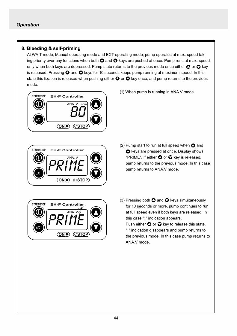
Operation
44
8 Bleeding amp self-primingAt WAIT mode Manual operating mode and EXT operating mode pump operates at max speed tak-ing priority over any functions when both and keys are pushed at once Pump runs at max speed only when both keys are depressed Pump state returns to the previous mode once either or key is released Pressing and keys for 10 seconds keeps pump running at maximum speed In this state this fixation is released when pushing either or key once and pump returns to the previous mode
(1) When pump is running in ANAV mode
EXT
EH-F ControllerSTARTSTOP
ON STOP
ANA V spm
(2) Pump start to run at full speed when and keys are pressed at once Display shows
PRIME If either or key is released pump returns to the previous mode In this case pump returns to ANAV mode
EXT
EH-F ControllerSTARTSTOP
ON STOP
ANA V
(3) Pressing both and keys simultaneously for 10 seconds or more pump continues to run at full speed even if both keys are released In this case indication appearsPush either or key to release this state indication disappears and pump returns to the previous mode In this case pump returns to ANAV mode
EXT
EH-F ControllerSTARTSTOP
ON STOP
ANA V
Operation
45
10 Error display and release(1) In case Input signals fall to 4 mA or below while
4-20 or 20-4 is set to ANA R mode pump stops with DISCN blinking and Err on dis-play
(2) This error state can be released by push-ing STARTSTOP key and pumps enters wait mode In this case check the wiring and input signals
EXT
EH-F ControllerSTARTSTOP
ON STOP
ANAR
Err
spm
EXT
EH-F ControllerSTARTSTOP
ON STOP
spm
9 Key lockKey lock function is to prevent pump from being operated by some other person than user If STARTSTOP key is pressed for five seconds or more when pump is running or stops all key operations become ineffective with LOCK indication on display This function can be released by pressing STARTSTOP key for 5 seconds while LOCK lights
EXT
EH-F ControllerSTARTSTOP
ON STOP
MAN spm
LOCK
46
Do not conduct a maintenance work with the wet hands It can cause an electric shock
Before dismantling pump be sure to turn off power and check the pump is not electrified Do not
start a dismantlement work after stopping the pump by pushing the STARTSTOP key only Put up
the sign of ldquoMaintenance work is in progressrdquo in order to prevent a pump switch from turning on
unintentionally during the work Release the pressure of discharge piping and drain the liquid from
the wet end parts And then clean the inside of pump head
Wear protective clothing such as a protective mask globes goggles and chemical-proof wear
according to the handled chemical liquid during the work
WARNING
5 Maintenance
1 Trouble shootingTrouble Cause Troubleshooting
Pump dose not start Faulty wiring or disconnection in wiring Voltage is too low Failure in the electronic circuit of control unit
Pump dose not suck liquidDischarge amount is low
Air suction from suction piping Valve gasket is not installed Valve set assembling direction is wrong Pump is air-locked Pump stroke length is too short Suction-sidedischarge-side valve is clogged with
foreign matter Adhesion of valve onto valve seat
Discharge amount fluctuates
Liquid leaks
Key operation is ineffective Key is locked Release key lock
Pump doesnt run
Pump is in waiting mode Signals are not coming for EXT operation Pump is in EXT setting mode Pump is suspended with STOP
Move to operation mode Check wiring and correct the wrong part Move to EXT operating mode Release STOP function
Abnormal noise
Suction-sidedischarge-side valve is clogged with foreign matters
The sound absorption gasket is worn out Bearing is worn out Spring is damaged
Piping vibrates due to pulsation Bearing is worn out Spring is damaged
Install a accumulator or an air chamber The end of pump life span The end of pump life span
Suction-sidedischarge-side valve is clogged with foreign matters
Air is trapped in pump Overfeeding Diaphragm is damaged
Fittings are not tightly closed Pump head is not tightened Diaphragm is damaged O ring and valve gasket are not installed O ring is damaged
Correct wiring Inspect power source and provide measurement Replace the whole unit
Arrange piping again Install valve gasket Reassemble valve set Carry out air elimination Drive pump with 100 stroke length to prime liquid Then
reset stroke length Disassemble inspect and clean Disassemble inspect and clean
Tighten fittings Tighten pump head Replace diaphragm Install O ring and valve gasket Replace O ring
Disassemble inspect and clean
Carry out air elimination Install a check valve or a back pressure valve Replace diaphragm
Disassemble inspect and clean
The end of pump life span The end of pump life span The end of pump life span
Abnormal vibration
Input pulse can not be read Signals are not coming Anti-chattering setting is not proper
Check wiring and correct the wrong part Change the setting properly
Analog signal input can not be read
Wrong wiring Signals are over acceptable loaded resistance
Check wiring and correct wrong part The load resistance is 200Ω Use some devise which can
accept the load resistance
47
CAUTION Check periodically whether the bolts fixing pump head are tightened Tighten them as needed
The bolts fixing pump head may loosen in operation Tightening torque 255Nbullm
Maintenance
3
bull Tighten joint where leakage has occurredbull The excessive air bubbles in the discharged liquid mean air suc-
tion has been caused in system Examine the piping and tighten joint on where leaks
Is there liquid leakage or air suction at any joints on pump or piping
2 Maintenance and inspection
1 Daily inspectionPay attention to the following points during pump operation Stop pump immediately upon detecting abnormality and take measures according to the item Troubleshooting When wear parts come to the life time replace them by new ones
No
1
2
Check Point Description
Does pump lift liquid normally
bull Is liquid normally fedbull Is suction pressuredischarge pressure at normal levelbull Has liquid undergone quality change crystallization or solidifica-
tion
Abnormal noise or vibrationbull Abnormal noise or vibration may happen from the abnormal func-
tioning of pump
EXT setting can not be stored
After EXT setting STARTSTOP key is pushed for EXT by mistake
Push EXT key to operate pump in EXT mode
ldquoPRIME is kept indicated and other operations are inac-cessible
Self-priming function is active Push either or key to release the function
Analog signal input can not be read and DISCN indication appears
Wrong wiring or disconnection Check wiring and correct the wrong part Refer to page 45
for how to release an error indication
Trouble Cause Troubleshooting
48
Maintenance
2 Wear partsWear parts should be replaced in proper period for a long period of pump operation It is recommended that follow-ing parts are always ready for the replacementVC V6 PC P6 types
Parts Qty Life span
Pum
p he
ad
Valve set
EH-F35 EH-F45 EH-F55middot70
2sets
8000hours
Diaphragm 1
Refer to exploded view
Bac
k pr
essu
re v
alve
1
2
Che
ck v
alve
7 6 1
8 11 1
Diaphragm seat 1
O ring
Poppet check valve (With check gasket)
Check valve spring Spacer
Diaphragm
O ring
Note Durability of wear parts depend on the pumped liquid temperature and pressure Time to be replaced mentioned as above is the estimation obtained by continuous pump-ing of clean water at ambient temperature
8000hours
4000hours
49
3 Dismantlement and assembly
Getting wet with or coming in contact with chemicals and toxic liquid is harmful Wear protective clothing such as a protective mask globes goggles and chemical-proof wear during the work
Risk of electrical shock Be sure to turn off power and confirm that pump and devices are not electrified before the work
Release the pressure inside pump and a discharge hose by opening an air bleed valve on piping prior to loosening the piping connections or the dismantlement of pump Dismantlement with the pressure inside pump could lead to liquid spillage
Be careful not to touch residual liquid when dismantling pump Some liquids are harmful for skin or component parts Wipe off liquid when the hand or the component parts come in contact with liquid
WARNING
CAUT ION
Hose
Hose stopperFitting spacer
O ring
Fitting nut
Fitting
Pumphead
Remove the fittingwith a spanner
1 Valve set replacement Dismantlement1 Loosen a fitting nut and remove the hose con-
nected to pump head Pay attention to the liquid dripping
2 Loosen a fitting with a spanner to remove it Then detach the valve set from pump head
Maintenance
50
AssemblyAssembly procedure is in reverse order to disas-sembly Pay attention to the following when assembling valve set DispositionInsertion direction of valve set The wrong dispositioninsertion direction of valve
set component can lead to leakage and less dis-charge amount
O ring is fitted properly1 Discharge side valve set mounting
Put valve set in pump head and screw a fitting into a pump head by hand and then re-tighten it by 14 turns with a spanner
2 Suction side valve set mountingPut valve set in connection port and screw the fitting into pump head by hand and then re-tighten it by 14 turns with spanner
Note Pay attention to the mounting direction of the spacer fitted to EH-F45(VC V6 PC)Make sure the cut portion on the spacer of suction side should be downward the one of discharge side should be upward
Suction side
Discharge side
O ringValve gasket
Valve gasket
Valve gasket
Valve guideValveValve seatSpacer
O ring
Valve gasketValve guideValveValve seat
Spacer
1714
11
1312
11
1312
17
17
14
14
14
11
31
1312
31
17
14
11
1312
12
13
11
14
EH-F35
EH-F45
EH-F5570
Suct
ion
side
Dis
char
ge s
ide
For b
oth
suct
ion
and
disc
harg
e si
deFo
r bot
h su
ctio
nan
d di
scha
rge
side
VC V6 PC P6 Type
Maintenance
51
Pay attention not to lose diaphragm spacer and to apply the correct number of diaphragm spacers 0 to several pieces of diaphragm spacers are put between retainer and plunger to adjust the position of diaphragm The number of spacers mounted depends on the pump model There are the models which do not have spacers
Maintenance
2 Diaphragm replacement Dismantlement1 Set stroke length to 0 by adjusting stroke length
adjustment knob
2 Remove the pump head from the pump body by loos-ening hex socket cap bolts
3 Rotate a diaphragm anti-clockwise to remove it from a plunger pin The diaphragm is screwed into the plunger pin
AssemblyAssembly is done in reverse order to disassembly Follow the steps below1 Make sure the stroke length of pump is set to 0
prior to an assembly Operate pump to set the stroke length to 0 and
stop it Then turn off power
2 Fit a rear diaphragm seat a retainer and a diaphragm spacer into new diaphragm via the threaded pin and screw the diaphragm into the plunger pin
Fit the concave side of retainer into the convex side of diaphragm Pay attention the retainer dose not come off
3 Set the stroke length to 100 Operate pump to set the stroke length to 100
and stop it Then turn off power4 Install a pump head to a pump body by tightening
the hex sock cap bolts equally Tightening torque is 255Nbullm
52
4 Accessories1 Connection port bore bull Check valve bull Back pressure valve
Note1 Check valves and back pressure valves are options2 Regarding the connection of the discharge side of back pressure valve
NPT38 and NPT12 taper pipe thread is used for BV-N-CR
Pump type Connection port bore Check valve Back pressure valve
EH-F35VC empty38timesempty12 hose CA-3VCH-C6 ndash
empty38timesempty12 hose CA-3VEH-C6 ndashempty38timesempty12 hose CA-3VH-C6 ndashempty38timesempty12 hose CA-3VCH-C6 ndashempty38timesempty12 hose CA-3VEH-C6 ndashempty38timesempty12 hose CA-3VH-C6 ndash
V6
empty38timesempty12 hose ndash BV-3NV-C6Rempty38timesempty12 hose ndash BV-3NE-C6Rempty38timesempty12 hose ndash BV-3NPV-C6Rempty58timesempty34 hose ndash BV-3NV-C7Rempty58timesempty34 hose ndash BV-3NE-C7Rempty58timesempty34 hose ndash BV-3NPV-C7R
PC
EH-F45VCV6PC
EH-F55VCV6PC
EH-F70VCV6PC
Maintenance
53
Maintenance
5 Exploded view
1 General view The extent of dismantlement is within the following exploded view
Diaphragm spacer
Retainer
(Back up retainer)55 bull 70 types
Pump body
Valve set
Valve set
Pump head
Diaphragm
Rear diaphragm sheet
54
2 Pump head (Hose connection type)
EH-F45 type EH-F35 type
4
28
2930
3
1114
131211
131217
1897
1
17
111312111312
3
3029
28
4
1920
1920 21
17
111312
31
3
3029
28
4
131217
189
7
11
3114
14
4
282930
3
1
21
1515
EH-F55 type
4
28
2930
3
11
131217
18
9
7
10
1
1920 21
17
111312
3
30
29
28
4
EH-F70 type
4
28
2930
3
14
11131217
18
9
7
10
1
1920 21 17
111312
3
30
29
28
4
15 15
14
1414
14
14 14
Note1 The back up retainer of No10 is only for EH-F55 bull 70 typesNote2 The figure inside ( ) in the above table is for EH-F45 bull 55 bull 70 typesNote3 The number of the diaphragm spacers (No18) is not constant None or a few spacers is inserted at
each diaphragmNote4 The figure inside ( ) in the above table is for EH-F70Note5 EH-F35 bull 55 bull 70 (VC V6 PC ) types require 2 valve gaskets and EH-F45 (VC V6 PC) types
require 4 of themNote6 The spacer on No31 is for EH-F45 type only
No Name Qty1 Pump head 13 Fitting 24 Fitting nut 27 Diaphragm 19 Retainer 110 Back up retainer 1 Note111 Valve guide 4 (2) Note212 Valve seat13 Valve14 Valve gasket
No Name Qty
17 O ring 218 Diaphragm spacer 1 Note319 Hex socket head bolt 6 (8) Note420 Spring washer21 Plain washer28 Hose stopper 229 Fitting spacer 230 O ring 231 Spacer 2 Note6
15 Rear diaphragm seat 1
2 (4) Note54 (2) Note24 (2) Note2
6 (8) Note46 (8) Note4
Maintenance
55
Maintenance
3 Pump head (Flange connection type) EH-F55 type
30
3
11
131217
18
9
7
10
1
1920 21
17
11
1312
3
30
EH-F70 type
15
EH-F45 type EH-F35 type
30
3
11131211
131217
1897
1
17
11131211
1312
3
30
1920
1920 21
17
111312
31
3
131217
189
7
11
31
30
3
1
30
21
1515
30
3
11131217
18
9
7
10
1
1920 21 17
11
1312
3
30
15
32
33
33
32
4
32
433
43332
32
334
43332
32
33
32
334
44
1414
14 14 14
1414
14
14 14
NoNo Name Qty1 Pump head 13 Fitting 24 Fitting nut 27 Diaphragm 19 Retainer 110 Back up retainer 1 Note111 Valve guide 4(2)Note212 Valve seat 4(2)Note213 Valve 4(2)Note214 Valve gasket 2(4)Note5
Name Qty
17 O ring 218 Diaphragm spacer 1 Note319 Hex socket cap bolt 6(8)Note420 Spring washer 6(8)Note421 Plain washer 6(8)Note430 O ring 2
33 Union 2
31 Spacer 2 Note6
15 Rear diaphragm seat 1
32 Flange 2
Note1 The back up retainer of No10 is only for EH-F55 bull 70 typesNote2 The figure inside ( ) in the above table is for EH-F45 bull 55 bull 70 typesNote3 The number of the diaphragm spacers (No18) is not constant None or a few spacers is inserted at
each diaphragmNote4 The figure inside ( ) in the above table is for EH-F70Note5 EH-F35 bull 55 bull 70 (VC V6 ) types require 2 valve gaskets and EH-F45 (VC V6) types require 4 of
themNote6 The spacer on No31 is for EH-F45 type only
56
4 Pump head (Flange connection horizontal suction port type) EH-F55 type
30
3
11
131217
18
9
7
10
1
1920 21
17
111312
3
30
EH-F70 Type
15
EH-F45 Type EH-F35 type
30
3
11131211
131217
1897
1
17
111312111312
3
30
1920
1920 21
17
11131231
3
131217
189
7
11
31
30
3
1
30
21
1515
30
3
11131217
18
9
7
10
1
1920 21 17
111312
3
30
15
32
33
32
433
43334
32
32
334
43334
32
33
44
34
32
334
34
32
334
32
35 353535
1414
14 14 14
1414
14
14 14
No Name Qty1 Pump head 13 Fitting 24 Fitting nut 27 Diaphragm 19 Retainer 110 Back up retainer 1 Note111 Valve guide 4 (2) Note212 Valve seat13 Valve
15 Rear diaphragm sheet 114 Valve gasket
No Name Qty
18 Diaphragm spacer 1 Note319 Hex socket cap bolt20 Spring washer21 Plain washer
31 Spacer 2 Note6
35 Pipe 1
32 Flange 2
34 Elbow 133 Union 2
17 O ring 2
30 O ring 2
4 (2) Note24 (2) Note22 (4) Note5
6 (8) Note4
4 (2) Note24 (2) Note2
Maintenance
Note1 The back up retainer of No10 is only for EH-F55 bull 70 typesNote2 The figure inside ( ) in the above table is for EH-F45 bull 55 bull 70 typesNote3 The number of the diaphragm spacers (No18) is not constant None or a few spacers is inserted at
each diaphragmNote4 The figure inside ( ) in the above table is for EH-F70Note5 EH-F35 bull 55 bull 70 (VC V6) types require 2 valve gaskets and EH-F45 (VC V6) types require 4 of
themNote6 The spacer on No31 is for EH-F45 type only
57
5 Check valve CA-3 type
1 2 3 4 5 6 7 8 11 9 10
16
14
13
15
12
3
15
17
16
1110
98
7
1
54
2
6
14
13
6 Back pressure valve BV-3N-R type
No No Name Qty10 Stopper 111 Diaphragm 112 Lower case 113 Fitting spacer Hose port 114 Hose stopper Ferrule 115 O ring 216 Nut 217 Fitting 1
Name Qty1 Upper case 12 Hexhead bolt (with PW SW) 43 Hex nut 44 Adjusting bolt 15 Hexnut 16 Plain washer 1
8 Spring 19 Retainer plate 1
7 Spring seat 1
NoNo Name Qty1 Fitting nut 12 Hose stopper 13 Fitting spacer 14 O ring 15 Valve case 16 Gasket 1
Name Qty7 Poppet valve 18 Spring 19 O ring 110 Valve fitting 111 Spacer 1
Maintenance
58
Maintenance
1 Outer dimension (Hose connection type) EH-F35 type
TUBING(38rdquotimes12rdquo)
38rdquotimes12rdquo
EH-F45 type
38rdquotimes12rdquo
38rdquotimes12rdquo
59
EH-F55 type
58rdquotimes34rdquo
58rdquotimes34rdquo
EH-F70 type
Maintenance
38rdquotimes12rdquo
38rdquotimes12rdquo
60
Maintenance
2 Outer dimension (Flange connection type) EH-F35 type
EH-F45 type
61
EH-F55 type
EH-F70 type
Maintenance
62
Maintenance
3 Outer dimension (Flange connection horizontal suction port type) EH-F35 type
EH-F45 type
63
EH-F55 type
EH-F70Type
Maintenance
httpwwwiwakipumpsjp
Read this manual before use of product
IWAKIElectromagnetic Metering Pump
EH-F series (North America)
Instruction ManualT596 0706
GermanyItalyDenmarkSwedenFinlandNorwayFranceUKSwitzerlandAustriaHollandSpainBelgiumUSA
TEL (49)2154 9254 0TEL (39)02 990 3931TEL (45)48 24 2345TEL (46)8 511 72900TEL (358)9 2742714TEL (47)66 81 16 60TEL (33)1 69 63 33 70TEL (44)1743 231363TEL (41)26 674 9300TEL (43)2236 33469TEL (31)297 241121TEL (34)943 630030TEL (32)1367 0200TEL (1)508 429 1440
AustraliaSingaporeIndonesiaMalaysiaTaiwanThailandHong KongChinaChinaChinaChinaPhilippinesKoreaVietnam
TEL (61)2 9899 2411TEL (65)6316 2028TEL (62)21 690 6606TEL (60)3 7803 8807TEL (886)2 8227 6900TEL (66)2 322 2471TEL (852)2 607 1168TEL (86)750 380 9018TEL (86)20 8435 0603TEL (86)10 6442 7713TEL (86)21 6272 7502TEL (63)2 888 0245TEL (82)2 3474 0523TEL (84)613 933456
IWAKI EUROPE GmbH IWAKI Italia SRL IWAKI Nordic AS IWAKI Sverige AB IWAKI Suomi Oy IWAKI Norge AS IWAKI France SA IWAKI PUMPS (UK) LTD IWAKI (Schweiz) AG IWAKI (Austria) GmbH IWAKI Holland BV IWAKI Iberica Pumps SA IWAKI Belgium nv IWAKI America Incorporated
FAX 2154 1028FAX 02 990 42888FAX 48 24 2346FAX 8 511 72922FAX 9 2742715FAX 66 81 16 61FAX 1 64 49 92 73FAX 1743 366507FAX 26 674 9302FAX 2236 33469FAX 297 273902FAX 943 628799FAX 1367 2030FAX 508 429 1386
IWAKI Pumps Australia Pty Ltd IWAKI Singapore Pte Ltd IWAKI Singapore (Indonesia Branch) IWAKIm Sdn Bhd IWAKI Pumps Taiwan Co Ltd IWAKI (Thailand) CoLtd IWAKI Pumps Co Ltd IWAKI Pumps (Guandong) Co Ltd GFTZ IWAKI Engineering amp Trading (Guangzhou) IWAKI Pumps Co Ltd (Beijing) IWAKI Pumps (Shanghai) Co Ltd IWAKI Chemical Pumps Philippines Inc IWAKI Korea CoLtd IWAKI Pumps Vietnam Joint Venture CoLtd
FAX 2 9899 2421FAX 6316 3221FAX 21 690 6612FAX 3 7803 4800FAX 2 8227 6818FAX 2 322 2477FAX 2 607 1000FAX 750 380 9078FAX 20 8435 9181FAX 10 6442 7712FAX 21 6272 6929FAX 2 843 3096FAX 2 3474 0221FAX 613 933399
( )Country codes
IWAKI COLTD 6-6 Kanda-Sudacho 2-chome Chiyoda-ku Tokyo 101-8558 JapanTEL(81)3 3254 2935 FAX3 3252 8892(httpwwwiwakipumpsjp)
This is patent pending product
- 107
- 47
- 48
- 49
- 50
- 3
- 4
- 64
- 102
- 101
- 78
- 79
- 91
- 81
- 100
- 99
- 84
- 86
- 85
- 87
- 22
- 23
- 73
- 72
- 26
- 98
- 28
- 27
- 31
- 32
- 29
- 30
- 95
- 34
- 33
- 96
- 35
- 36
- 37
- 38
- 40
- 39
- 41
- 42
- 59
- 58
- 45
- 7
- 6
- 46
- 5
- 8
- 9
- 74
- 75
- 10
- 11
- 61
- 60
- 15
- 14
- 62
- 63
- 16
- 17
- 18
- 19
- 92
- 94
- 93
- 103

Operation
45
10 Error display and release(1) In case Input signals fall to 4 mA or below while
4-20 or 20-4 is set to ANA R mode pump stops with DISCN blinking and Err on dis-play
(2) This error state can be released by push-ing STARTSTOP key and pumps enters wait mode In this case check the wiring and input signals
EXT
EH-F ControllerSTARTSTOP
ON STOP
ANAR
Err
spm
EXT
EH-F ControllerSTARTSTOP
ON STOP
spm
9 Key lockKey lock function is to prevent pump from being operated by some other person than user If STARTSTOP key is pressed for five seconds or more when pump is running or stops all key operations become ineffective with LOCK indication on display This function can be released by pressing STARTSTOP key for 5 seconds while LOCK lights
EXT
EH-F ControllerSTARTSTOP
ON STOP
MAN spm
LOCK
46
Do not conduct a maintenance work with the wet hands It can cause an electric shock
Before dismantling pump be sure to turn off power and check the pump is not electrified Do not
start a dismantlement work after stopping the pump by pushing the STARTSTOP key only Put up
the sign of ldquoMaintenance work is in progressrdquo in order to prevent a pump switch from turning on
unintentionally during the work Release the pressure of discharge piping and drain the liquid from
the wet end parts And then clean the inside of pump head
Wear protective clothing such as a protective mask globes goggles and chemical-proof wear
according to the handled chemical liquid during the work
WARNING
5 Maintenance
1 Trouble shootingTrouble Cause Troubleshooting
Pump dose not start Faulty wiring or disconnection in wiring Voltage is too low Failure in the electronic circuit of control unit
Pump dose not suck liquidDischarge amount is low
Air suction from suction piping Valve gasket is not installed Valve set assembling direction is wrong Pump is air-locked Pump stroke length is too short Suction-sidedischarge-side valve is clogged with
foreign matter Adhesion of valve onto valve seat
Discharge amount fluctuates
Liquid leaks
Key operation is ineffective Key is locked Release key lock
Pump doesnt run
Pump is in waiting mode Signals are not coming for EXT operation Pump is in EXT setting mode Pump is suspended with STOP
Move to operation mode Check wiring and correct the wrong part Move to EXT operating mode Release STOP function
Abnormal noise
Suction-sidedischarge-side valve is clogged with foreign matters
The sound absorption gasket is worn out Bearing is worn out Spring is damaged
Piping vibrates due to pulsation Bearing is worn out Spring is damaged
Install a accumulator or an air chamber The end of pump life span The end of pump life span
Suction-sidedischarge-side valve is clogged with foreign matters
Air is trapped in pump Overfeeding Diaphragm is damaged
Fittings are not tightly closed Pump head is not tightened Diaphragm is damaged O ring and valve gasket are not installed O ring is damaged
Correct wiring Inspect power source and provide measurement Replace the whole unit
Arrange piping again Install valve gasket Reassemble valve set Carry out air elimination Drive pump with 100 stroke length to prime liquid Then
reset stroke length Disassemble inspect and clean Disassemble inspect and clean
Tighten fittings Tighten pump head Replace diaphragm Install O ring and valve gasket Replace O ring
Disassemble inspect and clean
Carry out air elimination Install a check valve or a back pressure valve Replace diaphragm
Disassemble inspect and clean
The end of pump life span The end of pump life span The end of pump life span
Abnormal vibration
Input pulse can not be read Signals are not coming Anti-chattering setting is not proper
Check wiring and correct the wrong part Change the setting properly
Analog signal input can not be read
Wrong wiring Signals are over acceptable loaded resistance
Check wiring and correct wrong part The load resistance is 200Ω Use some devise which can
accept the load resistance
47
CAUTION Check periodically whether the bolts fixing pump head are tightened Tighten them as needed
The bolts fixing pump head may loosen in operation Tightening torque 255Nbullm
Maintenance
3
bull Tighten joint where leakage has occurredbull The excessive air bubbles in the discharged liquid mean air suc-
tion has been caused in system Examine the piping and tighten joint on where leaks
Is there liquid leakage or air suction at any joints on pump or piping
2 Maintenance and inspection
1 Daily inspectionPay attention to the following points during pump operation Stop pump immediately upon detecting abnormality and take measures according to the item Troubleshooting When wear parts come to the life time replace them by new ones
No
1
2
Check Point Description
Does pump lift liquid normally
bull Is liquid normally fedbull Is suction pressuredischarge pressure at normal levelbull Has liquid undergone quality change crystallization or solidifica-
tion
Abnormal noise or vibrationbull Abnormal noise or vibration may happen from the abnormal func-
tioning of pump
EXT setting can not be stored
After EXT setting STARTSTOP key is pushed for EXT by mistake
Push EXT key to operate pump in EXT mode
ldquoPRIME is kept indicated and other operations are inac-cessible
Self-priming function is active Push either or key to release the function
Analog signal input can not be read and DISCN indication appears
Wrong wiring or disconnection Check wiring and correct the wrong part Refer to page 45
for how to release an error indication
Trouble Cause Troubleshooting
48
Maintenance
2 Wear partsWear parts should be replaced in proper period for a long period of pump operation It is recommended that follow-ing parts are always ready for the replacementVC V6 PC P6 types
Parts Qty Life span
Pum
p he
ad
Valve set
EH-F35 EH-F45 EH-F55middot70
2sets
8000hours
Diaphragm 1
Refer to exploded view
Bac
k pr
essu
re v
alve
1
2
Che
ck v
alve
7 6 1
8 11 1
Diaphragm seat 1
O ring
Poppet check valve (With check gasket)
Check valve spring Spacer
Diaphragm
O ring
Note Durability of wear parts depend on the pumped liquid temperature and pressure Time to be replaced mentioned as above is the estimation obtained by continuous pump-ing of clean water at ambient temperature
8000hours
4000hours
49
3 Dismantlement and assembly
Getting wet with or coming in contact with chemicals and toxic liquid is harmful Wear protective clothing such as a protective mask globes goggles and chemical-proof wear during the work
Risk of electrical shock Be sure to turn off power and confirm that pump and devices are not electrified before the work
Release the pressure inside pump and a discharge hose by opening an air bleed valve on piping prior to loosening the piping connections or the dismantlement of pump Dismantlement with the pressure inside pump could lead to liquid spillage
Be careful not to touch residual liquid when dismantling pump Some liquids are harmful for skin or component parts Wipe off liquid when the hand or the component parts come in contact with liquid
WARNING
CAUT ION
Hose
Hose stopperFitting spacer
O ring
Fitting nut
Fitting
Pumphead
Remove the fittingwith a spanner
1 Valve set replacement Dismantlement1 Loosen a fitting nut and remove the hose con-
nected to pump head Pay attention to the liquid dripping
2 Loosen a fitting with a spanner to remove it Then detach the valve set from pump head
Maintenance
50
AssemblyAssembly procedure is in reverse order to disas-sembly Pay attention to the following when assembling valve set DispositionInsertion direction of valve set The wrong dispositioninsertion direction of valve
set component can lead to leakage and less dis-charge amount
O ring is fitted properly1 Discharge side valve set mounting
Put valve set in pump head and screw a fitting into a pump head by hand and then re-tighten it by 14 turns with a spanner
2 Suction side valve set mountingPut valve set in connection port and screw the fitting into pump head by hand and then re-tighten it by 14 turns with spanner
Note Pay attention to the mounting direction of the spacer fitted to EH-F45(VC V6 PC)Make sure the cut portion on the spacer of suction side should be downward the one of discharge side should be upward
Suction side
Discharge side
O ringValve gasket
Valve gasket
Valve gasket
Valve guideValveValve seatSpacer
O ring
Valve gasketValve guideValveValve seat
Spacer
1714
11
1312
11
1312
17
17
14
14
14
11
31
1312
31
17
14
11
1312
12
13
11
14
EH-F35
EH-F45
EH-F5570
Suct
ion
side
Dis
char
ge s
ide
For b
oth
suct
ion
and
disc
harg
e si
deFo
r bot
h su
ctio
nan
d di
scha
rge
side
VC V6 PC P6 Type
Maintenance
51
Pay attention not to lose diaphragm spacer and to apply the correct number of diaphragm spacers 0 to several pieces of diaphragm spacers are put between retainer and plunger to adjust the position of diaphragm The number of spacers mounted depends on the pump model There are the models which do not have spacers
Maintenance
2 Diaphragm replacement Dismantlement1 Set stroke length to 0 by adjusting stroke length
adjustment knob
2 Remove the pump head from the pump body by loos-ening hex socket cap bolts
3 Rotate a diaphragm anti-clockwise to remove it from a plunger pin The diaphragm is screwed into the plunger pin
AssemblyAssembly is done in reverse order to disassembly Follow the steps below1 Make sure the stroke length of pump is set to 0
prior to an assembly Operate pump to set the stroke length to 0 and
stop it Then turn off power
2 Fit a rear diaphragm seat a retainer and a diaphragm spacer into new diaphragm via the threaded pin and screw the diaphragm into the plunger pin
Fit the concave side of retainer into the convex side of diaphragm Pay attention the retainer dose not come off
3 Set the stroke length to 100 Operate pump to set the stroke length to 100
and stop it Then turn off power4 Install a pump head to a pump body by tightening
the hex sock cap bolts equally Tightening torque is 255Nbullm
52
4 Accessories1 Connection port bore bull Check valve bull Back pressure valve
Note1 Check valves and back pressure valves are options2 Regarding the connection of the discharge side of back pressure valve
NPT38 and NPT12 taper pipe thread is used for BV-N-CR
Pump type Connection port bore Check valve Back pressure valve
EH-F35VC empty38timesempty12 hose CA-3VCH-C6 ndash
empty38timesempty12 hose CA-3VEH-C6 ndashempty38timesempty12 hose CA-3VH-C6 ndashempty38timesempty12 hose CA-3VCH-C6 ndashempty38timesempty12 hose CA-3VEH-C6 ndashempty38timesempty12 hose CA-3VH-C6 ndash
V6
empty38timesempty12 hose ndash BV-3NV-C6Rempty38timesempty12 hose ndash BV-3NE-C6Rempty38timesempty12 hose ndash BV-3NPV-C6Rempty58timesempty34 hose ndash BV-3NV-C7Rempty58timesempty34 hose ndash BV-3NE-C7Rempty58timesempty34 hose ndash BV-3NPV-C7R
PC
EH-F45VCV6PC
EH-F55VCV6PC
EH-F70VCV6PC
Maintenance
53
Maintenance
5 Exploded view
1 General view The extent of dismantlement is within the following exploded view
Diaphragm spacer
Retainer
(Back up retainer)55 bull 70 types
Pump body
Valve set
Valve set
Pump head
Diaphragm
Rear diaphragm sheet
54
2 Pump head (Hose connection type)
EH-F45 type EH-F35 type
4
28
2930
3
1114
131211
131217
1897
1
17
111312111312
3
3029
28
4
1920
1920 21
17
111312
31
3
3029
28
4
131217
189
7
11
3114
14
4
282930
3
1
21
1515
EH-F55 type
4
28
2930
3
11
131217
18
9
7
10
1
1920 21
17
111312
3
30
29
28
4
EH-F70 type
4
28
2930
3
14
11131217
18
9
7
10
1
1920 21 17
111312
3
30
29
28
4
15 15
14
1414
14
14 14
Note1 The back up retainer of No10 is only for EH-F55 bull 70 typesNote2 The figure inside ( ) in the above table is for EH-F45 bull 55 bull 70 typesNote3 The number of the diaphragm spacers (No18) is not constant None or a few spacers is inserted at
each diaphragmNote4 The figure inside ( ) in the above table is for EH-F70Note5 EH-F35 bull 55 bull 70 (VC V6 PC ) types require 2 valve gaskets and EH-F45 (VC V6 PC) types
require 4 of themNote6 The spacer on No31 is for EH-F45 type only
No Name Qty1 Pump head 13 Fitting 24 Fitting nut 27 Diaphragm 19 Retainer 110 Back up retainer 1 Note111 Valve guide 4 (2) Note212 Valve seat13 Valve14 Valve gasket
No Name Qty
17 O ring 218 Diaphragm spacer 1 Note319 Hex socket head bolt 6 (8) Note420 Spring washer21 Plain washer28 Hose stopper 229 Fitting spacer 230 O ring 231 Spacer 2 Note6
15 Rear diaphragm seat 1
2 (4) Note54 (2) Note24 (2) Note2
6 (8) Note46 (8) Note4
Maintenance
55
Maintenance
3 Pump head (Flange connection type) EH-F55 type
30
3
11
131217
18
9
7
10
1
1920 21
17
11
1312
3
30
EH-F70 type
15
EH-F45 type EH-F35 type
30
3
11131211
131217
1897
1
17
11131211
1312
3
30
1920
1920 21
17
111312
31
3
131217
189
7
11
31
30
3
1
30
21
1515
30
3
11131217
18
9
7
10
1
1920 21 17
11
1312
3
30
15
32
33
33
32
4
32
433
43332
32
334
43332
32
33
32
334
44
1414
14 14 14
1414
14
14 14
NoNo Name Qty1 Pump head 13 Fitting 24 Fitting nut 27 Diaphragm 19 Retainer 110 Back up retainer 1 Note111 Valve guide 4(2)Note212 Valve seat 4(2)Note213 Valve 4(2)Note214 Valve gasket 2(4)Note5
Name Qty
17 O ring 218 Diaphragm spacer 1 Note319 Hex socket cap bolt 6(8)Note420 Spring washer 6(8)Note421 Plain washer 6(8)Note430 O ring 2
33 Union 2
31 Spacer 2 Note6
15 Rear diaphragm seat 1
32 Flange 2
Note1 The back up retainer of No10 is only for EH-F55 bull 70 typesNote2 The figure inside ( ) in the above table is for EH-F45 bull 55 bull 70 typesNote3 The number of the diaphragm spacers (No18) is not constant None or a few spacers is inserted at
each diaphragmNote4 The figure inside ( ) in the above table is for EH-F70Note5 EH-F35 bull 55 bull 70 (VC V6 ) types require 2 valve gaskets and EH-F45 (VC V6) types require 4 of
themNote6 The spacer on No31 is for EH-F45 type only
56
4 Pump head (Flange connection horizontal suction port type) EH-F55 type
30
3
11
131217
18
9
7
10
1
1920 21
17
111312
3
30
EH-F70 Type
15
EH-F45 Type EH-F35 type
30
3
11131211
131217
1897
1
17
111312111312
3
30
1920
1920 21
17
11131231
3
131217
189
7
11
31
30
3
1
30
21
1515
30
3
11131217
18
9
7
10
1
1920 21 17
111312
3
30
15
32
33
32
433
43334
32
32
334
43334
32
33
44
34
32
334
34
32
334
32
35 353535
1414
14 14 14
1414
14
14 14
No Name Qty1 Pump head 13 Fitting 24 Fitting nut 27 Diaphragm 19 Retainer 110 Back up retainer 1 Note111 Valve guide 4 (2) Note212 Valve seat13 Valve
15 Rear diaphragm sheet 114 Valve gasket
No Name Qty
18 Diaphragm spacer 1 Note319 Hex socket cap bolt20 Spring washer21 Plain washer
31 Spacer 2 Note6
35 Pipe 1
32 Flange 2
34 Elbow 133 Union 2
17 O ring 2
30 O ring 2
4 (2) Note24 (2) Note22 (4) Note5
6 (8) Note4
4 (2) Note24 (2) Note2
Maintenance
Note1 The back up retainer of No10 is only for EH-F55 bull 70 typesNote2 The figure inside ( ) in the above table is for EH-F45 bull 55 bull 70 typesNote3 The number of the diaphragm spacers (No18) is not constant None or a few spacers is inserted at
each diaphragmNote4 The figure inside ( ) in the above table is for EH-F70Note5 EH-F35 bull 55 bull 70 (VC V6) types require 2 valve gaskets and EH-F45 (VC V6) types require 4 of
themNote6 The spacer on No31 is for EH-F45 type only
57
5 Check valve CA-3 type
1 2 3 4 5 6 7 8 11 9 10
16
14
13
15
12
3
15
17
16
1110
98
7
1
54
2
6
14
13
6 Back pressure valve BV-3N-R type
No No Name Qty10 Stopper 111 Diaphragm 112 Lower case 113 Fitting spacer Hose port 114 Hose stopper Ferrule 115 O ring 216 Nut 217 Fitting 1
Name Qty1 Upper case 12 Hexhead bolt (with PW SW) 43 Hex nut 44 Adjusting bolt 15 Hexnut 16 Plain washer 1
8 Spring 19 Retainer plate 1
7 Spring seat 1
NoNo Name Qty1 Fitting nut 12 Hose stopper 13 Fitting spacer 14 O ring 15 Valve case 16 Gasket 1
Name Qty7 Poppet valve 18 Spring 19 O ring 110 Valve fitting 111 Spacer 1
Maintenance
58
Maintenance
1 Outer dimension (Hose connection type) EH-F35 type
TUBING(38rdquotimes12rdquo)
38rdquotimes12rdquo
EH-F45 type
38rdquotimes12rdquo
38rdquotimes12rdquo
59
EH-F55 type
58rdquotimes34rdquo
58rdquotimes34rdquo
EH-F70 type
Maintenance
38rdquotimes12rdquo
38rdquotimes12rdquo
60
Maintenance
2 Outer dimension (Flange connection type) EH-F35 type
EH-F45 type
61
EH-F55 type
EH-F70 type
Maintenance
62
Maintenance
3 Outer dimension (Flange connection horizontal suction port type) EH-F35 type
EH-F45 type
63
EH-F55 type
EH-F70Type
Maintenance
httpwwwiwakipumpsjp
Read this manual before use of product
IWAKIElectromagnetic Metering Pump
EH-F series (North America)
Instruction ManualT596 0706
GermanyItalyDenmarkSwedenFinlandNorwayFranceUKSwitzerlandAustriaHollandSpainBelgiumUSA
TEL (49)2154 9254 0TEL (39)02 990 3931TEL (45)48 24 2345TEL (46)8 511 72900TEL (358)9 2742714TEL (47)66 81 16 60TEL (33)1 69 63 33 70TEL (44)1743 231363TEL (41)26 674 9300TEL (43)2236 33469TEL (31)297 241121TEL (34)943 630030TEL (32)1367 0200TEL (1)508 429 1440
AustraliaSingaporeIndonesiaMalaysiaTaiwanThailandHong KongChinaChinaChinaChinaPhilippinesKoreaVietnam
TEL (61)2 9899 2411TEL (65)6316 2028TEL (62)21 690 6606TEL (60)3 7803 8807TEL (886)2 8227 6900TEL (66)2 322 2471TEL (852)2 607 1168TEL (86)750 380 9018TEL (86)20 8435 0603TEL (86)10 6442 7713TEL (86)21 6272 7502TEL (63)2 888 0245TEL (82)2 3474 0523TEL (84)613 933456
IWAKI EUROPE GmbH IWAKI Italia SRL IWAKI Nordic AS IWAKI Sverige AB IWAKI Suomi Oy IWAKI Norge AS IWAKI France SA IWAKI PUMPS (UK) LTD IWAKI (Schweiz) AG IWAKI (Austria) GmbH IWAKI Holland BV IWAKI Iberica Pumps SA IWAKI Belgium nv IWAKI America Incorporated
FAX 2154 1028FAX 02 990 42888FAX 48 24 2346FAX 8 511 72922FAX 9 2742715FAX 66 81 16 61FAX 1 64 49 92 73FAX 1743 366507FAX 26 674 9302FAX 2236 33469FAX 297 273902FAX 943 628799FAX 1367 2030FAX 508 429 1386
IWAKI Pumps Australia Pty Ltd IWAKI Singapore Pte Ltd IWAKI Singapore (Indonesia Branch) IWAKIm Sdn Bhd IWAKI Pumps Taiwan Co Ltd IWAKI (Thailand) CoLtd IWAKI Pumps Co Ltd IWAKI Pumps (Guandong) Co Ltd GFTZ IWAKI Engineering amp Trading (Guangzhou) IWAKI Pumps Co Ltd (Beijing) IWAKI Pumps (Shanghai) Co Ltd IWAKI Chemical Pumps Philippines Inc IWAKI Korea CoLtd IWAKI Pumps Vietnam Joint Venture CoLtd
FAX 2 9899 2421FAX 6316 3221FAX 21 690 6612FAX 3 7803 4800FAX 2 8227 6818FAX 2 322 2477FAX 2 607 1000FAX 750 380 9078FAX 20 8435 9181FAX 10 6442 7712FAX 21 6272 6929FAX 2 843 3096FAX 2 3474 0221FAX 613 933399
( )Country codes
IWAKI COLTD 6-6 Kanda-Sudacho 2-chome Chiyoda-ku Tokyo 101-8558 JapanTEL(81)3 3254 2935 FAX3 3252 8892(httpwwwiwakipumpsjp)
This is patent pending product
- 107
- 47
- 48
- 49
- 50
- 3
- 4
- 64
- 102
- 101
- 78
- 79
- 91
- 81
- 100
- 99
- 84
- 86
- 85
- 87
- 22
- 23
- 73
- 72
- 26
- 98
- 28
- 27
- 31
- 32
- 29
- 30
- 95
- 34
- 33
- 96
- 35
- 36
- 37
- 38
- 40
- 39
- 41
- 42
- 59
- 58
- 45
- 7
- 6
- 46
- 5
- 8
- 9
- 74
- 75
- 10
- 11
- 61
- 60
- 15
- 14
- 62
- 63
- 16
- 17
- 18
- 19
- 92
- 94
- 93
- 103
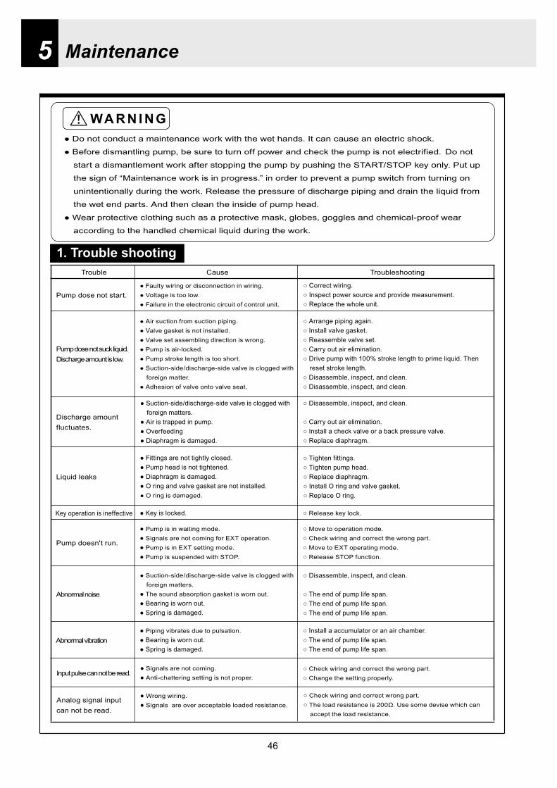
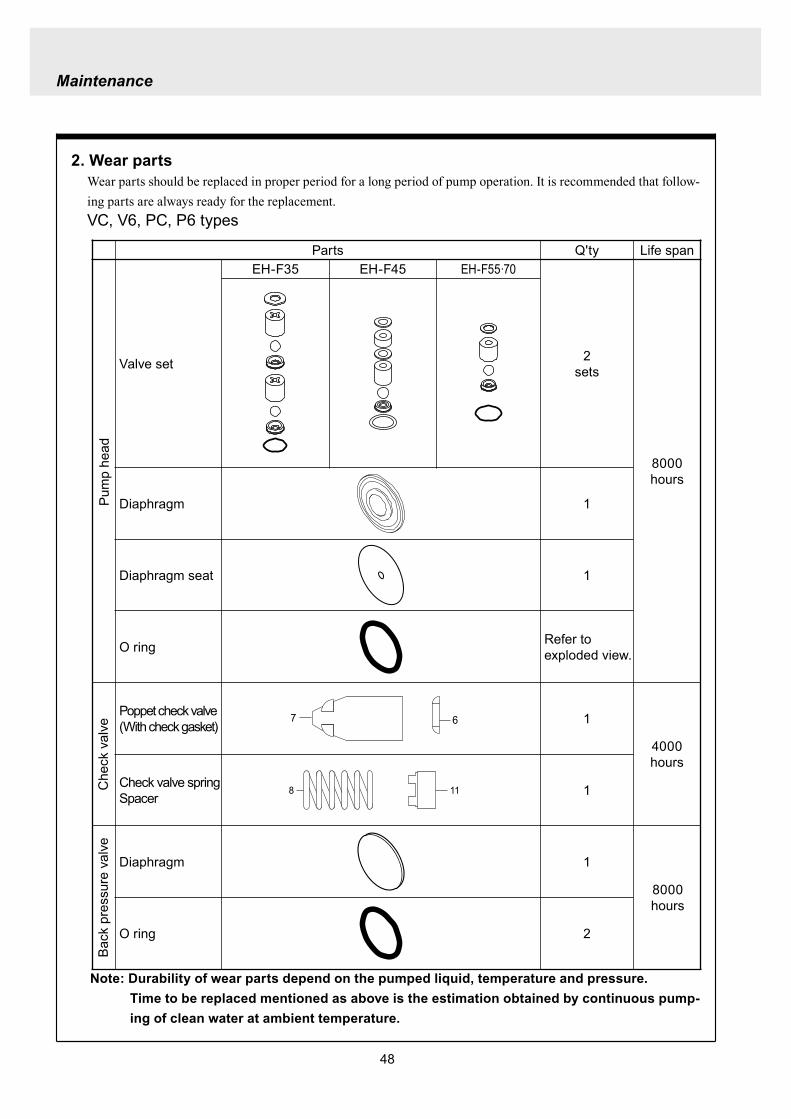
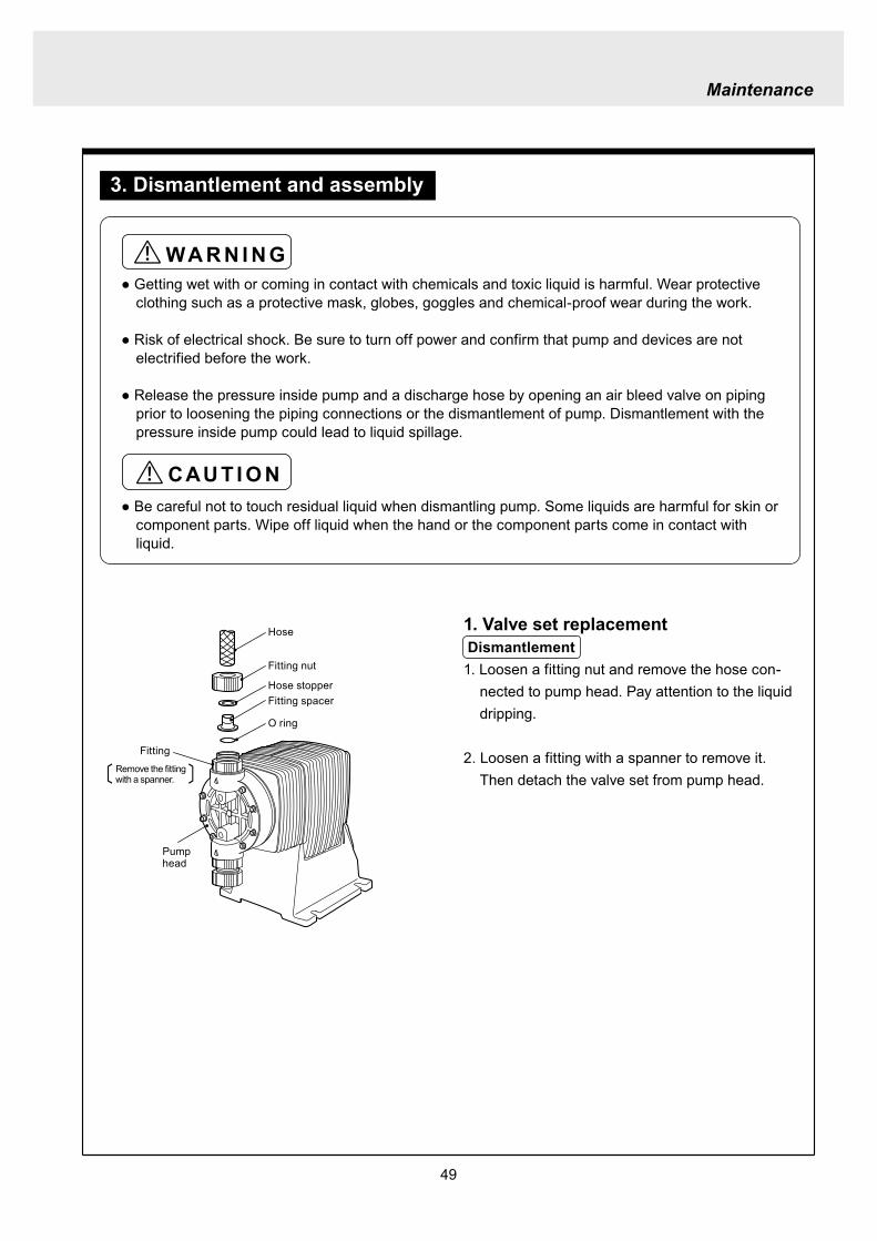
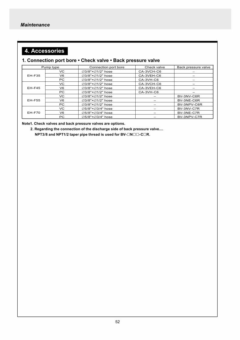

54
2 Pump head (Hose connection type)
EH-F45 type EH-F35 type
4
28
2930
3
1114
131211
131217
1897
1
17
111312111312
3
3029
28
4
1920
1920 21
17
111312
31
3
3029
28
4
131217
189
7
11
3114
14
4
282930
3
1
21
1515
EH-F55 type
4
28
2930
3
11
131217
18
9
7
10
1
1920 21
17
111312
3
30
29
28
4
EH-F70 type
4
28
2930
3
14
11131217
18
9
7
10
1
1920 21 17
111312
3
30
29
28
4
15 15
14
1414
14
14 14
Note1 The back up retainer of No10 is only for EH-F55 bull 70 typesNote2 The figure inside ( ) in the above table is for EH-F45 bull 55 bull 70 typesNote3 The number of the diaphragm spacers (No18) is not constant None or a few spacers is inserted at
each diaphragmNote4 The figure inside ( ) in the above table is for EH-F70Note5 EH-F35 bull 55 bull 70 (VC V6 PC ) types require 2 valve gaskets and EH-F45 (VC V6 PC) types
require 4 of themNote6 The spacer on No31 is for EH-F45 type only
No Name Qty1 Pump head 13 Fitting 24 Fitting nut 27 Diaphragm 19 Retainer 110 Back up retainer 1 Note111 Valve guide 4 (2) Note212 Valve seat13 Valve14 Valve gasket
No Name Qty
17 O ring 218 Diaphragm spacer 1 Note319 Hex socket head bolt 6 (8) Note420 Spring washer21 Plain washer28 Hose stopper 229 Fitting spacer 230 O ring 231 Spacer 2 Note6
15 Rear diaphragm seat 1
2 (4) Note54 (2) Note24 (2) Note2
6 (8) Note46 (8) Note4
Maintenance
55
Maintenance
3 Pump head (Flange connection type) EH-F55 type
30
3
11
131217
18
9
7
10
1
1920 21
17
11
1312
3
30
EH-F70 type
15
EH-F45 type EH-F35 type
30
3
11131211
131217
1897
1
17
11131211
1312
3
30
1920
1920 21
17
111312
31
3
131217
189
7
11
31
30
3
1
30
21
1515
30
3
11131217
18
9
7
10
1
1920 21 17
11
1312
3
30
15
32
33
33
32
4
32
433
43332
32
334
43332
32
33
32
334
44
1414
14 14 14
1414
14
14 14
NoNo Name Qty1 Pump head 13 Fitting 24 Fitting nut 27 Diaphragm 19 Retainer 110 Back up retainer 1 Note111 Valve guide 4(2)Note212 Valve seat 4(2)Note213 Valve 4(2)Note214 Valve gasket 2(4)Note5
Name Qty
17 O ring 218 Diaphragm spacer 1 Note319 Hex socket cap bolt 6(8)Note420 Spring washer 6(8)Note421 Plain washer 6(8)Note430 O ring 2
33 Union 2
31 Spacer 2 Note6
15 Rear diaphragm seat 1
32 Flange 2
Note1 The back up retainer of No10 is only for EH-F55 bull 70 typesNote2 The figure inside ( ) in the above table is for EH-F45 bull 55 bull 70 typesNote3 The number of the diaphragm spacers (No18) is not constant None or a few spacers is inserted at
each diaphragmNote4 The figure inside ( ) in the above table is for EH-F70Note5 EH-F35 bull 55 bull 70 (VC V6 ) types require 2 valve gaskets and EH-F45 (VC V6) types require 4 of
themNote6 The spacer on No31 is for EH-F45 type only
56
4 Pump head (Flange connection horizontal suction port type) EH-F55 type
30
3
11
131217
18
9
7
10
1
1920 21
17
111312
3
30
EH-F70 Type
15
EH-F45 Type EH-F35 type
30
3
11131211
131217
1897
1
17
111312111312
3
30
1920
1920 21
17
11131231
3
131217
189
7
11
31
30
3
1
30
21
1515
30
3
11131217
18
9
7
10
1
1920 21 17
111312
3
30
15
32
33
32
433
43334
32
32
334
43334
32
33
44
34
32
334
34
32
334
32
35 353535
1414
14 14 14
1414
14
14 14
No Name Qty1 Pump head 13 Fitting 24 Fitting nut 27 Diaphragm 19 Retainer 110 Back up retainer 1 Note111 Valve guide 4 (2) Note212 Valve seat13 Valve
15 Rear diaphragm sheet 114 Valve gasket
No Name Qty
18 Diaphragm spacer 1 Note319 Hex socket cap bolt20 Spring washer21 Plain washer
31 Spacer 2 Note6
35 Pipe 1
32 Flange 2
34 Elbow 133 Union 2
17 O ring 2
30 O ring 2
4 (2) Note24 (2) Note22 (4) Note5
6 (8) Note4
4 (2) Note24 (2) Note2
Maintenance
Note1 The back up retainer of No10 is only for EH-F55 bull 70 typesNote2 The figure inside ( ) in the above table is for EH-F45 bull 55 bull 70 typesNote3 The number of the diaphragm spacers (No18) is not constant None or a few spacers is inserted at
each diaphragmNote4 The figure inside ( ) in the above table is for EH-F70Note5 EH-F35 bull 55 bull 70 (VC V6) types require 2 valve gaskets and EH-F45 (VC V6) types require 4 of
themNote6 The spacer on No31 is for EH-F45 type only
57
5 Check valve CA-3 type
1 2 3 4 5 6 7 8 11 9 10
16
14
13
15
12
3
15
17
16
1110
98
7
1
54
2
6
14
13
6 Back pressure valve BV-3N-R type
No No Name Qty10 Stopper 111 Diaphragm 112 Lower case 113 Fitting spacer Hose port 114 Hose stopper Ferrule 115 O ring 216 Nut 217 Fitting 1
Name Qty1 Upper case 12 Hexhead bolt (with PW SW) 43 Hex nut 44 Adjusting bolt 15 Hexnut 16 Plain washer 1
8 Spring 19 Retainer plate 1
7 Spring seat 1
NoNo Name Qty1 Fitting nut 12 Hose stopper 13 Fitting spacer 14 O ring 15 Valve case 16 Gasket 1
Name Qty7 Poppet valve 18 Spring 19 O ring 110 Valve fitting 111 Spacer 1
Maintenance
58
Maintenance
1 Outer dimension (Hose connection type) EH-F35 type
TUBING(38rdquotimes12rdquo)
38rdquotimes12rdquo
EH-F45 type
38rdquotimes12rdquo
38rdquotimes12rdquo
59
EH-F55 type
58rdquotimes34rdquo
58rdquotimes34rdquo
EH-F70 type
Maintenance
38rdquotimes12rdquo
38rdquotimes12rdquo
60
Maintenance
2 Outer dimension (Flange connection type) EH-F35 type
EH-F45 type
61
EH-F55 type
EH-F70 type
Maintenance
62
Maintenance
3 Outer dimension (Flange connection horizontal suction port type) EH-F35 type
EH-F45 type
63
EH-F55 type
EH-F70Type
Maintenance
httpwwwiwakipumpsjp
Read this manual before use of product
IWAKIElectromagnetic Metering Pump
EH-F series (North America)
Instruction ManualT596 0706
GermanyItalyDenmarkSwedenFinlandNorwayFranceUKSwitzerlandAustriaHollandSpainBelgiumUSA
TEL (49)2154 9254 0TEL (39)02 990 3931TEL (45)48 24 2345TEL (46)8 511 72900TEL (358)9 2742714TEL (47)66 81 16 60TEL (33)1 69 63 33 70TEL (44)1743 231363TEL (41)26 674 9300TEL (43)2236 33469TEL (31)297 241121TEL (34)943 630030TEL (32)1367 0200TEL (1)508 429 1440
AustraliaSingaporeIndonesiaMalaysiaTaiwanThailandHong KongChinaChinaChinaChinaPhilippinesKoreaVietnam
TEL (61)2 9899 2411TEL (65)6316 2028TEL (62)21 690 6606TEL (60)3 7803 8807TEL (886)2 8227 6900TEL (66)2 322 2471TEL (852)2 607 1168TEL (86)750 380 9018TEL (86)20 8435 0603TEL (86)10 6442 7713TEL (86)21 6272 7502TEL (63)2 888 0245TEL (82)2 3474 0523TEL (84)613 933456
IWAKI EUROPE GmbH IWAKI Italia SRL IWAKI Nordic AS IWAKI Sverige AB IWAKI Suomi Oy IWAKI Norge AS IWAKI France SA IWAKI PUMPS (UK) LTD IWAKI (Schweiz) AG IWAKI (Austria) GmbH IWAKI Holland BV IWAKI Iberica Pumps SA IWAKI Belgium nv IWAKI America Incorporated
FAX 2154 1028FAX 02 990 42888FAX 48 24 2346FAX 8 511 72922FAX 9 2742715FAX 66 81 16 61FAX 1 64 49 92 73FAX 1743 366507FAX 26 674 9302FAX 2236 33469FAX 297 273902FAX 943 628799FAX 1367 2030FAX 508 429 1386
IWAKI Pumps Australia Pty Ltd IWAKI Singapore Pte Ltd IWAKI Singapore (Indonesia Branch) IWAKIm Sdn Bhd IWAKI Pumps Taiwan Co Ltd IWAKI (Thailand) CoLtd IWAKI Pumps Co Ltd IWAKI Pumps (Guandong) Co Ltd GFTZ IWAKI Engineering amp Trading (Guangzhou) IWAKI Pumps Co Ltd (Beijing) IWAKI Pumps (Shanghai) Co Ltd IWAKI Chemical Pumps Philippines Inc IWAKI Korea CoLtd IWAKI Pumps Vietnam Joint Venture CoLtd
FAX 2 9899 2421FAX 6316 3221FAX 21 690 6612FAX 3 7803 4800FAX 2 8227 6818FAX 2 322 2477FAX 2 607 1000FAX 750 380 9078FAX 20 8435 9181FAX 10 6442 7712FAX 21 6272 6929FAX 2 843 3096FAX 2 3474 0221FAX 613 933399
( )Country codes
IWAKI COLTD 6-6 Kanda-Sudacho 2-chome Chiyoda-ku Tokyo 101-8558 JapanTEL(81)3 3254 2935 FAX3 3252 8892(httpwwwiwakipumpsjp)
This is patent pending product
- 107
- 47
- 48
- 49
- 50
- 3
- 4
- 64
- 102
- 101
- 78
- 79
- 91
- 81
- 100
- 99
- 84
- 86
- 85
- 87
- 22
- 23
- 73
- 72
- 26
- 98
- 28
- 27
- 31
- 32
- 29
- 30
- 95
- 34
- 33
- 96
- 35
- 36
- 37
- 38
- 40
- 39
- 41
- 42
- 59
- 58
- 45
- 7
- 6
- 46
- 5
- 8
- 9
- 74
- 75
- 10
- 11
- 61
- 60
- 15
- 14
- 62
- 63
- 16
- 17
- 18
- 19
- 92
- 94
- 93
- 103
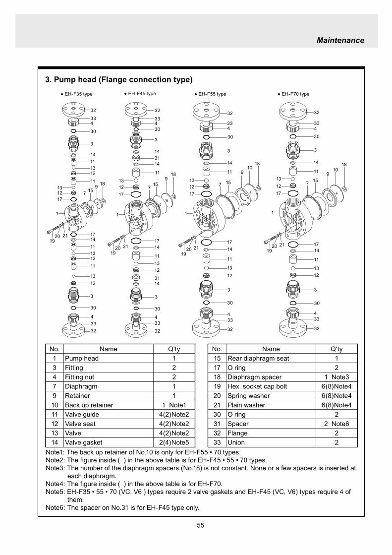
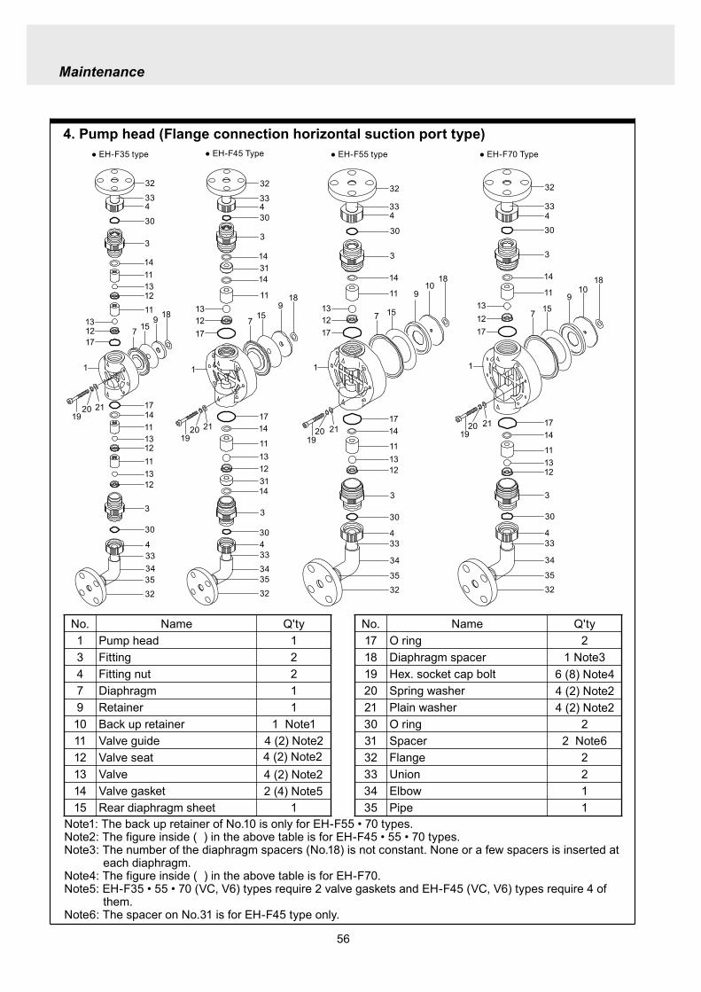
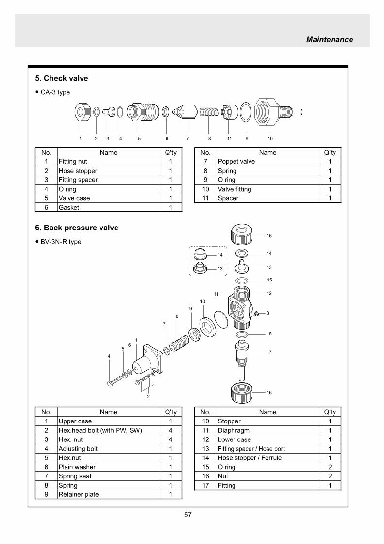
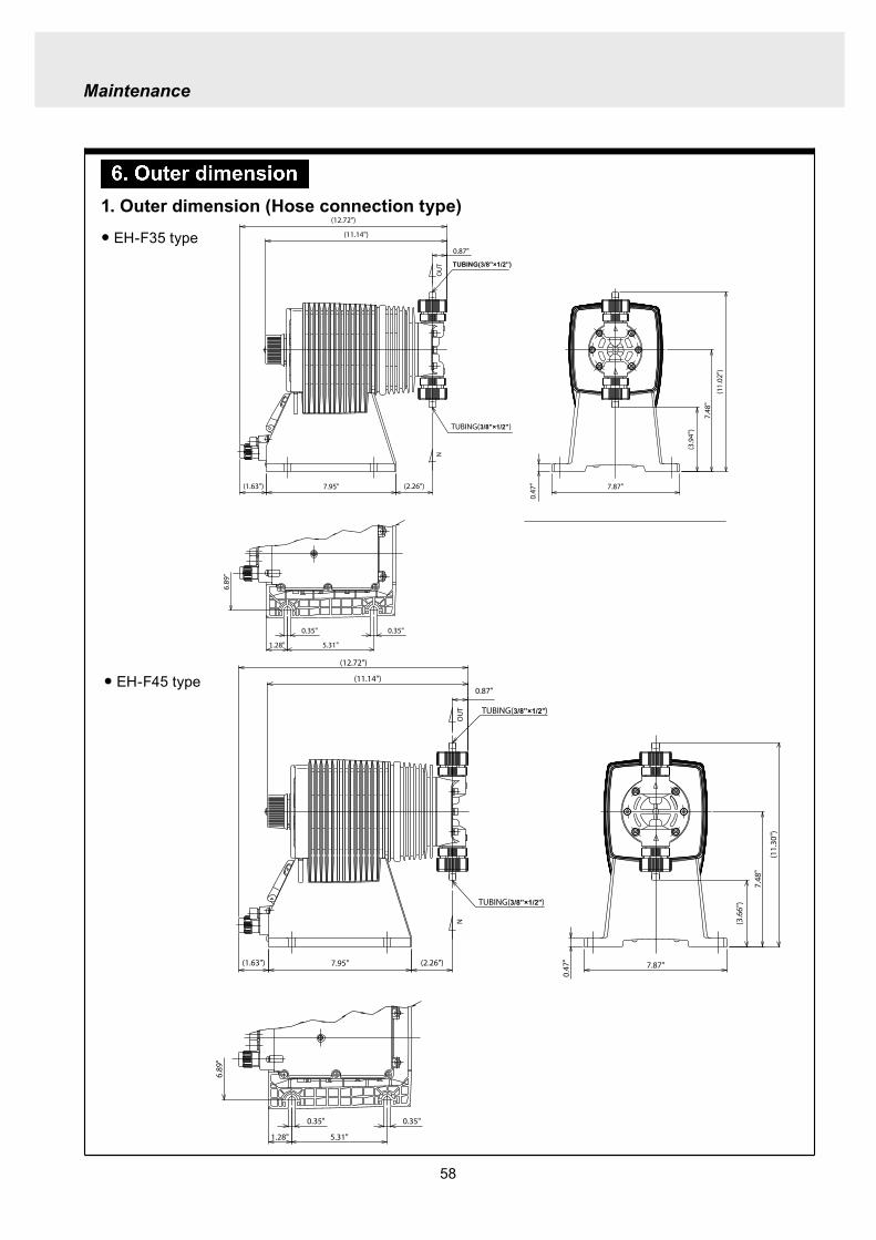
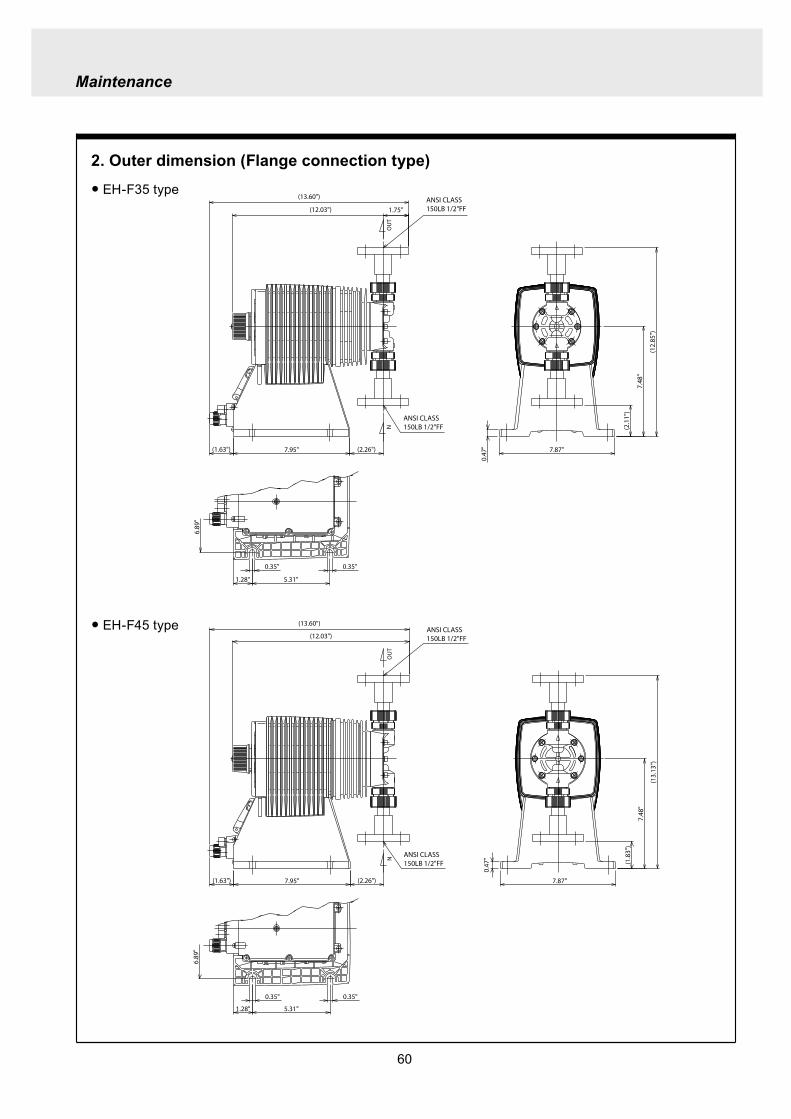
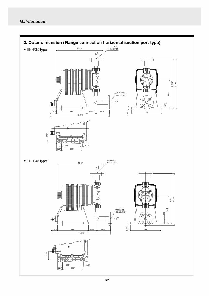