
Metering Pump Technologypumpsupplyinc.com/wp-content/uploads/Bulletin210-B_2005.pdfMetering Pump...
24
Transcript of Metering Pump Technologypumpsupplyinc.com/wp-content/uploads/Bulletin210-B_2005.pdfMetering Pump...


Metering Pump TechnologyBulletin 210
The Metering Pump. . . . . . . . . . . . . . . . . . . . . . . . . . 1Metering Pump Basic Components. . . . . . . . . . . . . . 1Metering Pump Characteristics. . . . . . . . . . . . . . . . . 2Capacity and Pressure Capabilities Chart . . . . . . . . 3Liquid End Designs . . . . . . . . . . . . . . . . . . . . . . . . . . 4
Packed Plunger . . . . . . . . . . . . . . . . . . . . . . . . . . . 4Disc Diaphragm . . . . . . . . . . . . . . . . . . . . . . . . . . 5Mechanically Actuated Diaphragm. . . . . . . . . . . . 6Metallic Diaphragm and Critical Service Head . . . 7
High Performance Diaphragm -Advanced Liquid End Design. . . . . . . . . . . . . . . . . . . 8Metering Pump Drive Mechanisms . . . . . . . . . . . . . 10
Hydraulic Bypass . . . . . . . . . . . . . . . . . . . . . . . . 10Polar Crank . . . . . . . . . . . . . . . . . . . . . . . . . . . . 11
CENTRAC . . . . . . . . . . . . . . . . . . . . . . . . . . . . . . . . 12Capacity Adjustment . . . . . . . . . . . . . . . . . . . . . . . . 14Modifications . . . . . . . . . . . . . . . . . . . . . . . . . . . . . . 15Metering Pump System Components . . . . . . . . . . . 16Other Milton Roy Products . . . . . . . . . . . . . . . . . . 18

1
The metering pump is a positive displacement chemical dosing device with the ability to vary capacity manually or automatically as process conditions require. It features a high level of repetitive accuracy and is capable of pump-ing a wide range of chemicals including acids, bases, corrosives or viscous liquids and slurries.
The pumping action is developed by a reciprocating piston which is either in direct contact with the process fluid, or is shielded from the fluid by a diaphragm. Diaphragms are actuated by hydraulic fluid between the piston and the diaphragm.Metering pumps are generally used in applications where one or more of the following conditions exist.
• Low flow rates in ml/hr or GPHare required
• High system pressure exists
• High accuracy feed rate isdemanded
• Dosing is controlled by computer,microprocessor, DCS, PLC, orflow proportioning
• Corrosive, hazardous, or hightemperature fluids are handled
• Viscous fluids or slurries need tobe pumped
Driver:The pump is usually driven by an
AC constant speed motor. Variable speed, pneumatic, and hydraulic drivers are also utilized.
Liquid End:The liquid end design and materi-
als of construction are determined by the service conditions, and the
nature of the fluid to behandled.Temperature, flow rate, fluid viscosity, cor-rosiveness and
other factors are considered.
Driver Mechanism: The drive mechanism translates
the rotary motion of the driver into reciprocating movement.Industrial duty pumps willsubmerge this portion of the pump in an oil bath to assure reliability during continuous operation.
Flow Adjustment:Pump flow rate is adjustable by
varying stroke length, effective stroke length, or stroking speed.Most metering pumps aresupplied witha micrometer screw adjustment similar to the one shown here. The micrometer can also be replaced by an elec-tronic or pneumatic actuator to adjust pump flow rate in response to process signal.
Liquid End
Driver
Drive Mechanism
FlowAdjustment
Metering Pump Basic Components
The Metering Pump

2
2.Unlike centrifugal pumps, flow rate is not greatly affected by changes in discharge pressure.
3.The metering pump flow vs. stroke character-istic curve is linear. It is not, however, necessar-ily proportional in that 50% stroke setting may not equal 50% flow. This is due to the fact that the calibration line may not pass through 0 on both axes simultaneously. By measuring flow at 2 stroke settings, plotting both points and drawing a straight line through them, other flow rates vs.stroke can be accurately predicted.The steady state accuracy of a correctly installed industrial grade metering pump isgenerally + 1.0% or better.Although a metering pump can generally be adjusted to pump at any flow rate between 0 and its maximum capacity, its accuracy is measured over a range determined by the pump's turndown ratio. Most metering pumps have a turndown ratio of 10:1, which simply means that the pump is within its accuracy rating anywhere between 10% and 100% of capacity. Centrac is an example of a new generation metering pump that features higher accuracy, and a greater turndown ratio of 100:1. Therefore, this design will accurately dose anywhere between 1% and 100% of capacity.
Metering Pump Characteristics
Metering Pump
CentrifugalPump
Flow Q
Pressure P
AverageFlow
Suction
Time
Peak Flow-x Average
Flow
One Complete Cycle
Discharge
FlowRate
Q
0 50 100
Point 2Q2, S2
Point 1Q1, S1
% Setting “S”Stroke Length or Driver Speed
1.The pumping action is developed by a reciprocating piston. This recip-rocating motion develops a flow easily represented by a sine wave. Actual flow rate is determined by the following formula:
Flow rate = Displacement x Cycles per unit of time.

3
The maximum capacity of each pump is determined by gear ratio, piston diameter, and motor RPM.
Maximum pressure rating applies to smaller piston diameters in each model. As the piston diameter and stroking speed increase, pressure capability decreases. See specific product data sheet for actual pres-sure rating at desired flow rate.
Capacities shown are for simplex pumps. For those pumps that can be supplied with more than one head, multiply the capacity by the number of heads to determine total capacity.
Capacity and Pressure CapabilitiesCapacity Per Head–GPH
0 5 10 20 30 40 50 75 100
150
200
350
500
750
1000
1500
2000
3000
24”
mRoy XT & XWMaximum Pressure
1800-3000 psiMaximum No. Heads
2
23”
mRoy XTMaximum–
1.6 GPH (6 LH)Minimum–
0.4 GPH (1.5 LH)
mRoy A & BMaximum Pressure
350-1500 psiMaximum No. Heads
2
mRoy AMaximum–
30 GPH (114 LH)Minimum–
0.065 GPH (.246 LH)
8”
13”-24”
maxRoy BMaximum Pressure
150 psiMaximum No. Heads
1
maxRoy BMaximum–
227 GPH (859 LH) Minimum–
13.5 GPH (51.1 LH )
Milroyal BMaximum Pressure
7500 psiMaximum No. Heads
8
Milroyal BMaximum–
500 GPH (1893 LH)Minimum–
0.11 GPH (42 LH)
Centrac BMaximum Pressure
1575 psiMaximum No. Heads
2
Centrac BMaximum–
550 GPH (2082 LH)Minimum–
0.45 GPH (100:1 Turndown)
121/4”- 271/2”
Centrac SMaximum Pressure
9000 psiMaximum No. Heads
2
Centrac SMaximum–
39.7 GPH (150 LH)Minimum–
4.0 GPH (15 LH)
11”
18”
Milroyal CMaximum Pressure
7500 psiMaximum No. Heads
5
Milroyal CMaximum–
2510 GPH (9500 LH)Minimum–
0.43 GPH (1.628 LH)
PrimeRoyalMaximum Pressure
30,000 psiMaximum No. Heads
3
PrimeRoyalMaximum–
2510 GPH (9500 LH)Minimum–
0.43 GPH (1.628 LH)
72”
mRoy BMaximum–
85 GPH (322 LH)Minimum–
0.475 GPH (1.79 LH)
mRoy XWMaximum–
6.7 GPH (25 LH)Minimum–
2.8 GPH (9.8 LH)
27”
MacRoy G & D Maximum Pressure
175 psiMaximum No. Heads
1
MacRoyMaximum–
300 GPH (1135 LH)Minimum–
0.018 GPH (0.068 LH)
mR
oy X
T
mR
oy X
WMilroyal D
Maximum Pressure3000 psi
Maximum No. Heads6
Milroyal DMaximum–
53 GPH (200 LH)Minimum–
0.0081 GPH (0.0307 LH)
25”

4
The liquid end, which is referred to as the wetted part of the pump, is selected
to meet the specific service condi-tions of the application. Required flow and pressure ratings are con-sidered, as well as the physical and chemical properties of the liquid.The liquid end's ability to protect the environment is also a major consideration when dealing with toxic or hazardous chemicals.
All liquid ends have several fea-
tures in common. First, the liquid is drawn into the wetted end by the rearward motion of a pis-ton, and expelled by the forward motion. To achieve this, the meter-ing pump is supplied with check valves at the suction and discharge connection points. The check valves contain and release the chemical based on system condi-tions and gravity.
During the suction portion of the stroke, the motion of the piston lifts
the suction ball check from its seat allowing liquid into the pump. At the same time, the piston's motion and system back pressure hold the upper check valve (discharge) closed.This is then reversed during the discharge stroke.
Check valves are available in sev-eral different designs and configura-tions. The choice of ball or poppet style is determined by Milton Roy's Engineering department based on capacity of the specific pump.
Most pumps feature either single or double ball configuration as standard. The user can also select single or double ball when the application is better served by one or the other. For example, slurries or liquids with large fibers or particles can cause a single ball to leak if particles are trapped between the ball and seat. Therefore, a double ball check offers more stability and accuracy. On the other hand, since each check valve causes some resistance in the flow path even when open, viscous fluids are better handled with a single ball suction check valve.
SingleBall
CheckValve
DoubleBall
CheckValve
PoppetStyle
CheckValve
Packed PlungerThe packed plunger style liquid end is the only
liquid end in which the piston is in direct contact with the process fluid. This direct contact offers a number of advantages, including: high suction and discharge pressure capabilities; high temper-ature resistance, and lowest NPSH requirements.
The reciprocating piston requires packing to seal the wetted parts from the atmosphere. This simple design is effective, but places limitations on the use of packed plunger pumps in certain applications.
Because a small amount of controlled leakage past the packing must be expected, this styleliquid end should not be used with hazardous or toxic chemicals. Additionally, the friction between the piston and the packing results in wear that increases leakage. Periodic packing adjustment is necessary to maintain volumetric efficiency. To avoid problems associated with leakage, consider a diaphragm style liquid end.
The packed plunger can handle pressures up to 15,000 psi, and temperatures to 600oF (with special modifications).
Available on: Milroyal B, Milroyal C, Milroyal D, Centrac, and Maxroyal.Standard Materials of Construction: 316 SS, Alloy 20, Cast Steel (larger models)
Liquid End Designs
Discharge
SuctionPiston
Discharge BallCheck Valve
ProcessFluid
ProcessFluid
BallCheck
Seat
Suction BallCheck Valve
Discharge BallCheck Valve
Grease Fitting
Packing Lantern Ring
Suction BallCheck Valve
Piston

5
Available on: mRoy A, mRoy B, Milroyal B, Milroyal CStandard Materials of Construction: 316 SS, Alloy 20, Plastic
ProcessFluid
HydraulicFluid
ReservoirHydraulic
Fluid
Discharge BallCheck Valve
Relief Valve
Piston
AutomaticAir-Bleed Valve
TeflonDiaphragm
Suction BallCheck Valve
ContourPlates
The disc diaphragm liquid end has a teflon diaphragm which acts as a barrier between the piston and the process fluid. The piston's pumping motion is applied to hydraulic fluid which causes the diaphragm to flex back and forth as the piston reciprocates.
The hydraulically actuated dia-phragm operates with equal pres-sure between the hydraulic and process fluids. This eliminates dia-phragm stress, since the pressure is essentially equal on both sides at all times. Two contour plates encase the diaphragm to contain its travel.
The hydraulic and process fluids pass through carefully engineered holes in the contour plates in order to come into contact with the diaphragm. Relief and refill valves control the volume of hydraulic fluid. An automatic air bleed valve continuously purges air from the hydraulic fluid.
The diaphragm style pump is sealed. It therefore is an excel-lent choice for hazardous, toxic, or corrosive chemicals. For extra protection, double diaphragm and leak detection modifications are available, although they are consid-
ered redundant since this design is extremely durable.
Because the process fluid must pass through relatively small holes in the contour plate, the disc dia-phragm liquid end is not the best choice for slurries. With the excep-tion of the mRoy P design, disc diaphragms are usually not the best choice when pumping viscous fluids.
The disc diaphragm is capable of handling fluids where the required injection pressure is 3500psi or greater and the fluid temperature exceeds 250oF.
Disc Diaphragm

Mechanically-actuated pumps operate with a plunger directly attached to the diaphragm. This attachment generally takes place from a bolt and clamp being placed through the plunger and through the diaphragm. The direct attachment of the piston to the diaphragm connects the pump's drive and motor to the liquid end. The motion of the pump drive moves the plunger back and forth, thereby causing suction from the supply tank and pumping the fluid of choice through the attached conveyance infrastructure. This series of pumps generally find pressure peaks at 175 PSI, but
are only limited to flow as a matter of wetted end volume.Maximum life of the pump can be achieved by replacing the diaphragm at the recommended service interval. Leak detection can be easily found from the air-filled chamber residing gener-ally at atmospheric pressure on the drive side of the liquid end.This provides the least expen-sive leak detection option in the marketplace.
As with any chemical where gas binding can be a problem, it is rec-ommended that a degassing valve be used to release off-gases from the agitation or pressure changes
experienced by a liquid having off-gas characteristics. Some of these liquids that can generate off-gases as a result of pressure losses are NaOCl, H2O2, and some specialty chemicals. Mechanically-actuated pumps work well in these applica-tions providing 10:1 turndown as a standard across the product line. The addition of VFD technology and remote stroke control will bring the turndown as highas 100:1.
Mechanically-actuated diaphragm pumps are easily maintained and provide years of service for little effort.
6
Liquid End Designs
The Milton Roy Family of mechanically-actuated diaphragm pump is called the MacRoy Series G. They represent the best balance between low pump cost and high quality performance. Because it has zero diaphragm leakage, it makes a great pump for critical and otherwise expensive chemicals or where envi-
ronmental issues are involved. The mechanically-actuated series is an excellent choice where slurries and abrasive chemicals are required up to the pump's maximum flow and pressure ranges. They are also well tolerant of high viscosity liquids providing an economical solution for a variety of difficult applications.
Mechanically Actuated Diaphragm Design
Available on: MacRoy, Standard Materials of Construction: 316 SS, Alloy 20, Plastic
HydraulicFluid
ProcessFluid
Set Screw
Check Valve Assembly
Check Valve Assembly
DiaphragmHead
Diaphragm Cap
Oil Seal
Slotted Pan Head Screw
DiaphragmAssembly
DiaphragmAssembly

7
The Milton Roy Series of Metallic Diaphragms are unparalleled for use in critical, high pressure appli-cations such as oil and gas platforms and specialty industrial applications. They are especially useful where temperatures and pressures of both the environment and the process chemical can be vari-
able or otherwise difficult. The Metallic diaphragm lines are preferred for their longevity and durability in many difficult applications.
Metallic Diaphragm Liquid End and Critical Service Head
Available on: Milroyal C and PrimeRoyal: 316 SS, Alloy 20, Plastic
Metallic diaphragm metering pumps are hydraulically-actuated in the same manner and style as a standard hydraulically-actuated drive liquid end. However, the teflon or other usual diaphragm material is replaced with a special metal alloy particular to the application toproduce higher pressures than more
traditional materials. The metal design of the diaphragm also man-ages difficult chemicals such as abrasives, slurries and other special requirements compounds easier and more efficiently than its morestandard version.
Many oil and gas offshore drill-ing platforms require metallic
diaphragms because of their high reliability and longevity. In any appli-cation where critical service is required, the Milton Roy Metallic Diaphragm is the product of choice for these chemical dosing situations.
DiaphragmHead
Suction BallCheck Valve
DiaphragmHead Bolts /Nuts
DisplacementChamber
Set Screws
PlungerAdapterNut
Plunger Sleeve
Plunger
Detail B
Diaphragm
O-Ring
O-Ring
O-Ring BackupO-Ring
BackupO-Ring
Screws
HydraulicFluid
ProcessFluid

8
The High Performance Diaphragm liquid end, HPD, combines all of the best characteristics of traditional liquid ends into one technologically advanced design. Its operating characteristics and simplicity of opera-tion make it the best pump to consider first for most metering pump applications.
HPD operation is similar to the disc diaphragm in that it is hydraulically actuated and utilizes the same shape and diaphragm. It is similar to a tubular diaphragm in the respect that the process fluid has a “straight through” path through the liquid end. Its low NPSH requirements are similar to that of a packed plunger liquid end. But the primary advantages of the HPD are the unique design features that separate it from tra-ditional designs.
The MARS Advantage A hydraulically actuated diaphragm
liquid end design requires a refill system to compensate for hydraulic fluid that bleeds past the piston or through an air bleed valve during nor-mal operation. Hydraulic fluid is also expelled from the chamber through the internal relief valve when the sys-tem experiences excess pressure, and therefore must also be replenished.
The HPD features a Mechanically Actuated Refill System (MARS) that offers a number of advantages over traditional refill systems. To under-stand the advantages of MARS, tra-ditional refill systems must first be explored.
Traditional DesignsTraditional designs use a system
that refills the chamber when a vacuum is created by the inability of the diaphragm to move beyond the hydraulic contour plate. It also refills when the suction is momentarily or permanently starved by accidental valve closure, insufficient NPSH, or other similar occurrences. When this happens, the hydraulic fluid chamber is overfilled because a vacuum has been created even though the diaphragm has not been able to travel rearward.To avoid diaphragm rupture due to overfilled hydraulic oil, a process side contour plate stops the diaphragm's forward travel, and forces the hydrau-lic relief valve to open, thus expelling the excess fluid.
The contour plate is a concave (actually, concavo-convex) disc that supports the diaphragm and limits its travel. The plate has a series of holes bored through it to permit the fluid
to come into contact with the dia-phragm. The pattern and size of these holes requires careful engineering to maintain the contour plate strength required to withstand the force of the diaphragm experienced at operating pressure.
The hydraulic contour plate does not cause any problems in pump operation since the hydraulic fluid passes easily through the contour plate holes. However, a process con-
tour plate, required by traditional disc diaphragm liquid ends, places limita-tions on the types of process fluids the pump can handle (such as slur-ries) since the process fluid must also pass through contour plate holes. The process contour plate also creates a pressure loss which raises the NPSH requirement of the liquid end.
The MARS SystemThe MARS System eliminates the
need for a process contour plate by assuring that the hydraulic fluid can only be refilled when the diaphragm has traveled all the way back to the hydraulic contour plate. The dia-phragm presses against the MARS valve, which only then permits a pop-pet valve to open from the vacuum created by insufficient hydraulic fluid.(See the illustration lower right)
Hydraulic overfill is therefore impossible. With the process con-tour plate gone, the straight through path of the process liquid makes the HPD a perfect choice for slurries and viscous materials. It also lowers the NPSH requirements of the pump, since pressure loss through a process contour plate is eliminated.
The MARS system also simplifies HPD start-up. Unlike other hydrau-lic liquid ends, the refill valve does not need adjustment. Additionally, since the HPD hydraulic fluid can-not be overfilled, there is no need to perform delicate procedures to synchronize hydraulic fluid balances (a difficult task required for tubular and other double diaphragm liquid ends). With the HPD, you just fill the reservoirs, and turn it on.
Traditional Liquid End with Process and Hydraulic contour Plates (refillsystem not shown)
Typical Contour Plate(Section cutaway)
High Performance Diaphragm...
Discharge
Suction
Process Contour Plate
ProcessFluid
Hydraulic SideContour Plate
Hydraulic Fluid
Piston
Diaphragm

9
The HPD features a pre-shaped PTFE/elastomer composite disc diaphragm.
On the process side, the chemi-cal resistance of PTFE is utilized.On the hydraulic side, the elasto-mer imparts favorable elastic and mechanical factors.
The composite diaphragm elimi-nates the inherent problems of pure PTFE diaphragms. PTFE tends to cold flow when compressed between two metal parts (such as those required to seal the hydrau-lic side from the process side).The HPD composite diaphragm features an integral "O" ring seal around the perimeter of the dia-phragm, which provides a better seal between hydraulic and process fluids than conventional diaphragm materials.
The HPD is capable of handling pressures up to 3025 psi and tem-peratures up to 300oF (with spe-cial modifications).
Available on: Milroyal B, Milroyal C, Milroyal D, Centrac and Maxroyal.Standard Materials of Construction: 316SS, Alloy 20, Plastic.
HPD Preshaped Composite Diaphragm
MARS System Operation
Preshaped Composite
Diaphragm.
Figure 1Diaphragm (A) and piston (C) are full forward. Mars valve (B) in for-ward position holds poppet valve (D) closed, preventing refill line hydraulic oil from entering the chamber.
Figure 2Diaphragm (A) and piston (C) are full rearward. Mars valve (B) is also rear-ward due to diaphragm position, thus freeing poppet (D) to open if required. Poppet (D) is shown closed, indicating hydraulic oil refill is not required.
Figure 3Diaphragm (A) and piston (C) are full rearward, once again forcing Mars valve (B) to its rearward position, which allows poppet (D) to open if required. Low oil volume creates a vacuum and opens pop-pet, permitting hydraulic fluid to enter the chamber from the refill line.
...Advanced Liquid End Technology
Full side view of HPD Liquid End on MilRoyal Drive
Air Bleed/Relief Valve
Piston
Hydraulic Refill Line
RemovableCheck Valve
CompositeDiaphragm
Mechanically Actuated Refill System (MARS)
MARS Valve Poppet
ProcessFluid
HydraulicFluid
Reservoir HydraulicFluid
PTFE Elastomer
A
B
C
D
A C
D
B
D
A C
B
Standard Materials:316SS. Alloy 20, Plastic.
Milroyal BHPD Low Flow

All Milton Roy drive mechanisms feature gears that are submerged in an oil bath to assure long life. Capacity can be adjusted while the pump is running or stopped, + 1.0% accuracy over a 10:1 turn-down ratio.
Hydraulic By-PassThe hydraulic by-pass mechanism features a piston with a constant stroke length that pumps hydraulic fluid,
thus transferring the pumping motion to a diaphragm. Therefore, this type of drive can only mate with a hydrauli-cally actuated diaphragm liquid end.
Capacity is varied by changing the location of a hydraulic by-pass port over the piston's path of travel. If the port is positioned at 50% of the piston's stroke length, hydraulic fluid will be relieved through the port during the first half of the piston's stroke, and pumped against the diaphragm during the remaining half. This type of drive is often called "hydraulic lost motion," because a portion of the piston's travel does not transmit pumping energy when the capacity adjustment is less than 100%. Both the mRoy and the Maxroy are hydraulic by-pass style pumps. Both develop reciprocating piston motion by way of a worm gear set and eccentric.
maxRoy B In the maxRoy, capacity is varied by positioning a stroke adjust sleeve over by-pass ports bored through the hollow
piston. When operating at 100%, the ports are covered, which traps hydraulic fluid in the hydraulic pumping chamber.Once trapped, the piston's pumping action forces the hydraulic fluid to flex the diaphragm.
A cup valve, which is attached to the diaphragm, closes all hydraulic paths to the diaphragm when it has reached the full forward position. This eliminates a process contour plate, as well as excessive hydraulic pressure on the diaphragm, since any excess hydraulic fluid in the hydraulic pumping chamber cannot reach the diaphragm, and is
forced through the internal relief valve to the fluid reservoir.
The maxRoy drive features:
• Maximum flow rates between 135 GPHand 227 GPH
• Maximum discharge pressures of 150 psi
The maxRoy is an excellent choice formid-range metering pump capacity at low pressure. Its design is more economical than high pressure pumps in the same capacity range, without sacrificing ruggedness and accuracy. The "straight through" process fluid path allows maxRoy to be applied to many of the same services as the HPD liquid end.
mRoy A, mRoy BIn the mRoy, the piston pumps
hydraulic fluid, which either forces the diaphragm to flex, or is relieved through the by-pass port. A control valve positions the port based on a desired capacity setting.
The mRoy drive with its standarddisc diaphragm liquid end features:
• Simplex or Duplex liquid ends
• Maximum capacities rangingbetween 0.43 GPH and 85 GPH(170 GPH Duplex)
• Maximum pressures up to 1800 psi
The mRoy drive with it’s standard disc dia-phragm liquid end.
Eccentric
Metering Pump Drive Mechanisms
HydraulicFluid
Reservoir HydraulicFluid
WormGear Set
PistonHydraulic Oilin Pumping ChamberSuction
Discharge
Eccentric
Stroke Adjust Sleeve
Cup Valve
DiaphragmCapacity Adjustment
By-PassPorts
Worm Gear Set
StrokeLength
Suction
DischargeControlValve
MotorBy-Pass Control
PlungerBy-Pass Port
Diaphragm
HydraulicFluid
Reservoir HydraulicFluid
ProcessFluid
10

11
To achieve a high thrust capac-ity and extend component life, the Milroyal B and C polar crank drives feature a pressurized lubrication sys-
tem. This positive oil pressure lubri-cation ensures long bearing life and permits the Milroyal pump to operate at very high suction and discharge
pressures.As the cross-
head moves forward during the discharge stroke, oil from the reservoir is drawn up through a ball check into a cavity in the
crosshead. During the suction (rear-ward) stroke the lubricant is trapped.It is then forced through the cross-head, into the crosshead connecting rod bearing, through the hollow con-necting rod, and finally to the crank connecting rod bearing. By forcing the oil through this path, every moving part is lubricated during every com-plete cycle of the pump.
To reduce the wear of moving parts and extend oil life, a magnetic strainer cleans the oil before it enters the pressurized system.
The unique polar crank drive is the heart of the Milroyal series metering pump. It is
considered the most advanced and reliable variable stroke length drive available in high pressure/high flow industrial duty metering pumps.
In the polar crank drive, a high speed worm gear reduces the RPM supplied by the motor, and provides the lower RPM to a rotating crank. A connecting rod with spherical bear-ings on each end links the crank to the crosshead and piston assembly.
The worm gear and crank assembly pivots in an arc about the worm shaft center to change stroke length. The piston stroke length is determined by the angle of the assembly.
For example, when the pump is at zero stroke, the worm/crank assem-bly is in a vertical position. (Figure 1) The crank then rotates in a vertical plane and one end of the connecting rod revolves with it. The crosshead and the piston remain stationary because no reciprocating action is produced. When the pump is adjust-ed full stroke (or maximum capacity), the rotating crank is moved to its maximum angle from the vertical axis.(Figure 2) At the top of the rotation cycle the connecting rod is pushed forward, moving the crosshead and
piston to the full forward position at the end of the discharge stroke. As the crank continues to rotate, the angle of the crank causes the con-necting rod to pull the crosshead and piston until it reaches the full rearward position at which point the connecting rod has reached the bottom of the rotation cycle.
Regardless of the stroke length setting, the top of the rotation cycle always forces the crosshead and the piston to the full forward position at the end of each discharge stroke.This assures complete scavenging of the liquid end during each stroke cycle.
The angle of the polar crank can be adjusted in infinite increments
between zero and maximum stroke for extremely accurate controlled volume pump settings.
Polar Crank
Lubricating OilRelief Valve
Lubricating Oil
Worm Shaft
Worm Gear
Connecting RodMagnetic Strainer
Crosshead
Piston
MicrometerStroke
Adjustment
This illustration demonstrating the polar crank at full and zero strokes
Worm Shaft
MicrometerCapacityControl
Worm GearRotating Crank
Lubricating Oil
Lubricating Oil Relief Valve
Figure 1Zero Stroke
ConnectingRod
CrossHead Worm
GearRotating Crank
Suction
Discharge
StrokeLength
Figure 2Full Stroke
The Milroyal polar crank drive features:
• Maximum capacity rangesbetween 0.033 GPH (125mL/hr.)and 2510 GPH depending onframe size, stroking speed, andplunger diameter
• Discharge pressures up to7500 psi
• Up to 8 pumps multiplexedand driven by one motor
• HPD, packed plunger, discdiaphragm, or tubulardiaphragm liquid ends
Pressurized Lubrication System

Centrac's impressive operatingcharacteristics are the result of a unique constant stroke length drive mechanism that depends on a spe-cial electronic variable speed drive to vary pump flow rate. This offers a number of advantages.
Traditional designs utilize worm gear sets to convert motor rotation to reciprocating motion through an eccentric or similar mechanism. Worm gears are the best choice when the drive mechanism is required to incorpo-rate a vari-able stroke length adjustment.They oper-ate well at high rotary speeds, due to an oil shield that develops between the gear surfaces. Unfortunately, they lose that shield at lower speeds, which causes wear and raises motor torque requirements. This limits worm gears to a 10:1 turndown ratio.
Centrac, on the other hand, uti-lizes a special helical gear set. Since there is no need for stroke length adjustment, the gear set is very simple. Also, helical gears are known for operating with low noise and low friction. Combined with a basic scotch yoke mechanism to develop
reciprocating motion, this gear set runs quietly and efficiently with few moving parts. All moving parts are submerged in oil to ensure long life.
The graph below indicates the greatest advantage of Centrac's special gear design. The flat torque curve (vs. the worm gear set) allows Centrac to operate at or below 1% of speed without placing extra demand on the motor, thus permit-ting Centrac's 100:1 turndown ratio.
The simple drive mechanism also allows Centrac to be easily duplexed within the same housing by adding a second piston and liquid end opposite the primary liquid end. Centrac's capacity can therefore be doubled economi-cally and efficiently.
Centrac's Advanced Electronic Variable Speed Drive
Conventional AC and DC variablespeed drives are limited to turn-down ratios between 5:1 and 30:1.This is insufficient to take advantage of the turndown capabilities of Centrac's gear design.
New technology in brushless DC motors and controllers has created advanced drives capable of strong operation at low speeds. Centrac's
variable speed drive delivers rated torque at less than 1% (100:1 turndown) of maximum rated RPM while main-taining steady state speed control at bet-ter than +0.1%. It is the perfect match for Centrac's drive mecha-nism.
12
Centrac represents a new concept in metering pump drive design. It is the first
true innovation in metering pump drives to be introduced in decades.
Centrac was developed by combin-ing the highest level of gear reduction design, and the latest technology in electronic variable speed drives. The
result is a metering pump that boasts twice the accuracy over a turndown ratio ten times greater than tradi-tional designs.
Centrac's name clearly announces its capabilities:
CENT-100:1 turndown ratioR-Response & ReliabilityAC - + 0.5% steady state accuracy
Centrac is different from tradi-tional designs in many ways. The most significant way is the close relationship between the driver and drive mechanism and how they enhance overall pump performance.To understand Centrac better, these two design elements and their inter-dependence need to be explored.
Advanced Drive Technology
CENTRAC – The Automatic Process
CENTRAC ScotchYoke Drive
Torque vs. Motor Speed-CENTRAC and Worm Gears
Motor Speed-RPM
200
180
160
140
120
Block transfers Rotating Eccentric Motion to Reciprocating Motion
FullLoad
0 10 20 50 100 175 200
Low Speed Eccentric & Gear
Motor Drive Gear (18 to 1800 RPM)
10:1 Turndown
Typical of Worm Gear Pump Drives
100%
1700 1800
100:1 Turndown
Operator Control Station
Centrac's Unique Gear Reduction System
Piston
+
% o
f Mot
or T
orqu
e R
equi
red
Typical of CENTRAC
+

13
Centrac's variable speed drivefeatures:
• 100:1 turndown ratio
• + 0.1% steady state speedcontrol
• smart commutation - permitsaccurate feedback signal
• no brushes (low maintenance)
• constant torque at low speeds - permits efficient driver sizing
100:1 Turndown RatioThe flexibility of a 100:1 turn-
down ratio permits Centrac to be applied where a wide range of dosage rates are required. It also provides built-in growth potential by pumping efficiently in systems requiring a fraction of the pump's capacity for the short term dur-ing start-up or early phases of an expanding project. Centrac provides all this without compromising accu-racy or drive power.
ResponseCentrac responds instantly to
changes in dosage rate. Its con-stant stroke length does not upset the balance within the liquid end hydraulic system, that is, hydrau-
lic fluid volume remains constant.When the hydraulic balance is dis-turbed, as in variable stroke length designs, the full result of dosage changes can take minutes or hours.
Centrac's instant response provides smoother operation in closed loop or automated systems. It also assures proper dosage at all time in systems requiring very close dosage tolerance.
AccuracyCentrac's + 0.5% steady state
accuracy over its full turndown ratio is a result of the constant stroke length, and the precise speed control of Centrac's drive. This level of accuracy provides maximum chemical economy while assuring stable automatic operation and opti-mum process quality.
Centrac's features include:
• 100:1 turndown ratio
• + 0.5% steady state accuracy
• Instant response to dosagechanges
• Simple but robust design forreliability
• Precise feedback signal
• Efficient drive sizing
• Mates with advanced HPD liquidend for maximum performance
• Capacity range between 0.45GPH minimum and 1100 GPHmaximum
• Discharge pressures up to1575 psi
• Economical duplex configuration availability
• Compact design higher capacityin a small footprint
Metering Pump
LiquidEnd
MountingSurface
Main Gear
Driver ShaftGear Assembly
Optional Duplex Configuration
Motor Mount
EccentricEccentric CageCrosshead
Connection Diagram
Drive Motor
Motor Control Optional Remote Operator Control
AC Input Power Remote Speed (Flow Rate)Control Signal
Speed(Flow Rate)OutputSignal

14
Metering pumps allow the user to vary capacity as the process requires. All Milton Roy metering pumps permit adjustment whether the pump is running or not.With the exception of the Centrac (see Centrac drive), Milton Roy pumps are supplied with a manual
micrometer for performing manual capacity adjustments. Depending on the type of drive mechanism and the application requirements, one of several capacity adjustment options can be supplied.
Capacity Adjustment
Manual MicrometerThe manual micrometer can be
used to adjust the metering pump's capacity anywhere between 0 and 100%. While not directly propor-tional to flow, this calibrated adjust-ment can be used to accurately set pump capacity based on the pump performance curve within + 1.0%over the turndown ratio.
Electronic ActuatorOption Available for: mRoy A & B, MaxRoy, Milroyal B & C
The Milton Roy Electronic Actuator responds to electronic process signals or remote manual adjust- ments. In addition, a local handwheel is provided to permit manual adjustments when unpowered.
Milton Roy's electronic actuator is different from electric actuators in that it utilizes electroniclimits. It is built around stepper motor technology, which allows it to travel precisely to position without overshoot or hunting.
This design also provides superior operating characteristics such as:
• 100% duty cycle• + 0.5% position accuracy or better• low maintenance
Remote control stations are available for local/remote selection and manual capacity adjustment.
Specifications:
• NEMA 4 (Explosion proofavailable)
• 4-20 mA input signalstandard
• Direct or reverse acting
Pneumatic ActuatorsOption Available for: mRoy A & B, Milroyal B & CAutomatic systems that supply a pneumatic process signal benefit from the Milton Roy pneumatic actuator. A separate air control panel is available for remote control and auto/manual switching.
Specifications:
• 3-15 or 3-27 psi pneumatic signal• Direct or reverse acting• Requires 60 psi supply air pressure
ManualMicrometer
• 1-5 VDC stroke position output signal
• Single phase 50/60 cycle 115 VAC
Electronic Actuator on mRoy A
Pneumatic Actuator

15
Milton Roy's diaphragm liquid ends are, by design, leakproof and durable.In some applications, however, added assurance is desired to protect the pump from hostile chemicals, or protect the process from contami-nation by hydraulic fluids. For these situations, Milton Roy has developed a highly reliable diaphragm rupture detection system.
The system consists of two sepa-rate diaphragms, a hollow interme-diate ring, and a pressure gauge or switch. During the normal opera-
tion, the two diaphragms are pushed tightly together and are separated only around their outside edge by the intermediate ring. The rupture detection system senses a pressure only when a diaphragm ruptures. The system is not affected by changes in pump discharge pressures.
This system is available for metal-lic liquid end mRoys, maxRoys, and HPD's. A different design centered around sensing changes in conductiv-ity is also available for a number of liquid ends.
ModificationsDouble Diaphragm With Diaphragm Rupture Detection System
Milton Roy offers a wide variety of standard pumps to satisfy most applications. In addition, our Applications Engineering department is capable of supplying specialty engineered products.
Application Engineering: Custom Modifications
Capabilities include:
• Special liquid end materialsincluding diaphragms, diaphragmheads, check valves, etc.
• Special piston diameters
• High temperature or pressuremodifications
• Unique multiplex arrangements
• Application counseling
• Special sensors, indications, orinstrument interface
• Special drive modifications orgear ratios
16
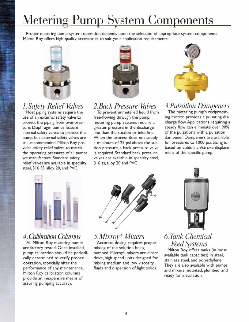
Proper metering pump system operation depends upon the selection of appropriate system components.Milton Roy offers high quality accessories to suit your application requirements.
Metering Pump System Components
4.Calibration ColumnsAll Milton Roy metering pumps
are factory tested. Once installed, pump calibration should be periodi-cally determined to verify proper operation, especially after the performance of any maintenance. Milton Roy calibration columns provide an inexpensive means of assuring pumping accuracy.
5.Mixroy® MixersAccurate dosing requires proper
mixing of the solution being pumped. Mixroy® mixers are direct drive, high speed units designed for mixing medium and low viscosity fluids and dispersion of light solids.
6.Tank ChemicalFeed Systems
Milton Roy offers tanks (in most available tank capacities) in steel, stainless steel, and polyethylene.They are also available with pumps and mixers mounted, plumbed, and ready for installation.
1.Safety Relief ValvesMost piping systems require the
use of an external safety valve to protect the piping from over-pres-sure. Diaphragm pumps feature internal safety valves to protect the pump, but external safety valves are still recommended. Milton Roy pro-vides safety relief valves to match the operating pressures of all pumps we manufacture. Standard safety relief valves are available in specialty steel, 316 SS, alloy 20, and PVC.
2.Back Pressure ValvesTo prevent unmetered liquid from
free-flowing through the pump, metering pump systems require a greater pressure in the discharge line than the suction or inlet line.When the process does not supply a minimum of 25 psi above the suc-tion pressure, a back pressure valve is required. Standard back pressure valves are available in specialty steel, 316 ss, alloy 20 and PVC .
3.Pulsation DampenersThe metering pump's reciprocat-
ing motion provides a pulsating dis-charge flow. Applications requiring a steady flow can eliminate over 90% of the pulsations with a pulsation dampener. Dampeners are available for pressures to 1000 psi. Sizing is based on cubic inch/stroke displace-ment of the specific pump.

17
Typical Installation
Pump
3PulsationDampener
2Back
Pressure Valve
1SafetyValve
To Process
4CalibrationColumns
7Strainer
6Tank
5
BallValve
BallValve
BallValve
BallValve
Tank Cover
PipePlugWire
Screen
Fiberglass
Balls
Wire Screen
LowerHousing
Bushing PipePlug
7.Strainers/SludgeTrapsThe metering pump's check valves
should be protected from particles and debris by installing a strainer in the suction line.
When pumping concentrated sulfu-ric acid, a sludge trap is required to trap sludge particles while providing easy cleaning or flushing.
Foot valves and strainers are avail-able for applications that pump fluid from replaceable drums. "Y" type strainers can also be supplied for in-line protection in standard systems.
8.Chemical Dosing Systems
Milton Roy offers the "RoyPak" family of chemical dosing pre-engineered systems. The standard RoyPak provides manual control and all accessories to allow for proper operation.
The RoyPak Setpoint paces the dosing from your single input.The RoyPak Setpoint Plus uses a line of instruments to provide a full closed-loop solution.
9.InstrumentsMilton Roy offers a full line of
water quality meters for use as a stand-alone or in conjunction with the RoyPak system.
Water quality - including PH, ORP, chlorine residuals, DO (dis-solved oxygen) - and other neces-sary water quality measurements are available.

18
Streaming Current DetectorMilton Roy's Streaming Current Detector
(SCD) is used to monitor and control coagulants in water or wastewater treatment.The SCD is an on-line instrument, therefore consistent effluent quality is assured.
In addition to water and wastewater treat-ment, the SCD is widely used in paper making, petroleum, food, chemical, and other industries where close control of coagulant or charge altering chemicals are beneficial.
Electronic ActuatorsA broad line of electronic actuators, similar to those used on Milton Roy pumps, is available for control valve
actuation and other applications requiring precision and dependability. These advanced electronic actuators out-perform standard electric designs by utilizing stepper motor technology.
Other Milton Roy Products
Milton Roy's electronic actuators offer the following advantages:
• 100% duty cycle
• Electronic limit switches
• Direct to position operation-nohunting or overshoot
• Rotary or linear designs
• AC and DC units
• Responds to 4-20 mA, split range,digital and other process signals
• Maximum torque - 3800 in-lbs(317 ft-lbs)
• Maximum thrust - 1100 lbs
• Optional controllers and failsafe units
The Milton Roy Family of Streaming Current Detectors

Notes

Notes


Bulletin 210Revision B 12/05Bulletin 210Revision B 12/05