Electric Reciprocating Compressor Installation · PDF fileElectric Reciprocating Compressor...
12
Electric Reciprocating Compressor Installation Guide Simplicity. It’s What We Do. Compressed Air Systems, LLC 2626 Skyway Drive Grand Prairie, TX, 75052 1-800-531-9656 Fax 972-352-6364 www.compressed-air-systems.com Notice: Air compressors should only be installed trained installation personnel call 800-531-9656 to find a local trained air compressor service technician. Warning: Read all installation steps, compressor package operation manual, notices and warnings prior to beginning compressor package installation. Failure to do so can result in personal injury or damage to compressor package. Warning: Always wear proper protective eye wear, hearing protection, and other mandated safety clothing and devices when installing compressor packages Notice: Compressor package should not be mounted to a moving piece of equipment that will be moving while the compressor package is in operation. The compressor package should not be mounted to a piece of equipment that adds additional vibration to the compressor package. The compressor package is only designed to handle its own organic vibration during operation. Failure to follow either one of these guidelines may result in pre-mature failure of compressor package, components and/or personal injury. ATTENTION: All incoming electrical power connections are to be made on the main motor contactor(s) DO NOT attach incoming power wires to package pressure switch. This will result in electrical component damage not covered under warranty. Warning: Before beginning steps 6-17 verify power supply is off to compressor disconnect, and compressor package NOTICE: To ensure full compressor tank warranty all tank mounted compressor packages must be mounted on factory supplied vibration isolation pads.
Transcript of Electric Reciprocating Compressor Installation · PDF fileElectric Reciprocating Compressor...

Electric Reciprocating Compressor
Installation Guide
Simplicity. It’s What We Do. Compressed Air Systems, LLC 2626 Skyway Drive Grand Prairie, TX, 75052 1-800-531-9656 Fax 972-352-6364
www.compressed-air-systems.com
Notice: Air compressors should only be installed trained installation personnel call 800-531-9656 to find a local trained air compressor service technician.
Warning: Read all installation steps, compressor package operation manual, notices and warnings prior to beginning compressor package installation. Failure to do so can result in personal injury or damage to compressor package.
Warning: Always wear proper protective eye wear, hearing protection, and other mandated safety clothing and devices when installing compressor packages
Notice: Compressor package should not be mounted to a moving piece of equipment that will be moving while the compressor package is in operation. The compressor package should not be mounted to a piece of equipment that adds additional vibration to the compressor package. The compressor package is only designed to handle its own organic vibration during operation. Failure to follow either one of these guidelines may result in pre-mature failure of compressor package, components and/or personal injury.
ATTENTION: All incoming electrical power connections are to be made on the main motor contactor(s) DO NOT attach incoming power wires to package pressure switch. This will result in electrical component damage not covered under warranty.
Warning: Before beginning steps 6-17 verify power supply is off to compressor disconnect, and compressor package
NOTICE: To ensure full compressor tank warranty all tank mounted compressor packages must be mounted on factory supplied vibration isolation pads.

3 Phase Motor Requirments (Copper wire must be THW, THHN-THWN, XHHW) No solid core wireNOTE: Wire size is based on being within 30ft of main electrical panel installation further would need a qualified electrian to properly size the wire to account for voltage dropHorse Power Voltage Circuit Breaker
Trip RatingMinimum Wire Size
Horse Power Voltage Circuit Breaker Trip Rating
Minimum Wire Size
3 200 20 14 30 200 150 2
3 230 20 14 30 230 125 3
3 460 15 14 30 460 80 8
3 575 15 14 30 575 60 8
5 200 35 12 40 200 200 1/O
5 230 30 14 40 230 175 1
5 460 15 14 40 460 100 6
5 575 15 14 40 575 80 6
7.5 200 50 10 50 200 200 3/O
7.5 230 45 10 50 230 200 2/O
7.5 460 20 14 50 460 125 4
7.5 575 20 14 50 575 100 6
10 200 60 8 60 200 250 4/O
10 230 60 10 60 230 225 3/O
10 460 35 14 60 460 125 3
10 575 25 14 60 575 125 4
15 200 90 6 75 200 300 300
15 230 80 6 75 230 300 250
15 460 45 10 75 460 150 1
15 575 40 12 75 575 125 3
20 200 100 4 100 200 400 500
20 230 90 4 100 230 400 350
20 460 60 10 100 460 200 2/O
20 575 50 10 100 575 175 1
25 200 125 3
25 230 125 4
25 460 70 8
25 575 60 10
NOTE: Some rotary screw compressors have additional drive motors for the coolings fans these need to be taken into account when sizing the electrical system
NEC (National Electric Code) Guide Lines1 Phase Motor Requirments (Copper wire must be THW, THHN-THWN, XHHW) No solid core wireNOTE: Wire size is based on being within 30ft of main electrical panel installation further would need a qualified electrian to properly size the wire to account for voltage dropHorse Power Voltage Instantaneous Trip Circuit Breaker Rating Circuit Breaker Trip Rating Minimum Wire Size
1.5 115 30 40 12
1.5 230 15 20 14
2 115 50 50 10
2 230 30 30 14
3 115 50 70 8
3 230 30 40 12
5 230 50 60 10
7.5 230 70 80 8
10 230 90 100 4
NOTE: Some rotary screw compressors have additional drive motors for the coolings fans these need to be taken into account when sizing the electrical system

Warning: Always wear proper protective eye wear, hearing protection, and other mandated safety clothing and devices when installing compressor packages
ATTENTION: All incoming electrical power connections are to be made on the main motor contactor(s) DO NOT attach incoming power wires to package pressure switch. This will result in electrical component damage not covered under warranty.
NOTICE: To ensure full compressor tank warranty all tank mounted compressor packages must be mounted on factory supplied vibration isolation pads.
Notice: Compressor package should not be mounted to a moving piece of equipment that will be moving while the compressor package is in operation. The compressor package should not be mounted to a piece of equipment that adds additional vibration to the compressor package. The compressor package is only designed to handle its own organic vibration during operation. Failure to follow either one of these guidelines may result in pre-mature failure of compressor package, components and/or personal injury.
Step 1
Verify compressor package install site can handle weight load of compressor package.(Note: this should have been done prior to the sale of the compressor package)Notice: Installing compressors on the roof, mezzanine, 2nd story or higher of a building can result in higher DBA readings for the compressor package as well as additional vibration
Step 2Make sure compressor installation site is clear of debris and has adequate space around were the compressor will sit for service (minimum of 24in.) and ventilation (must be able to get clean fresh air through oil/air cooler during operation, without recirculating cooler hot air discharge) If site is excessively dusty or dirty due to grinding, sanding, or due to the nature of the selected application site a new site should be sought out.
Step 3Make sure site voltage for compressor installation is correct(When reading voltage read across the lines to get and exact voltage. On single phase units read across L1 (Line 1) and L2 (Line 2) to get the operational voltage. On 3 phase units read across L1 to L2, then L2 to L3 (Line 3), then from L1 to L3 this gives the most accurate reading of the voltage. It is also recommended to read the voltage at both the main electrical panel and at the compressor disconnect to check for voltage drops prior to installation) A. 208-230 volt compressors can operate on voltages from 207-253 volts B. 460-480 volt compressor can operate on voltage from 420-505 volts C. On either 208-230 or 460-480 volt compressor packages; the lower the site voltage, the more amps the compressor
motor will draw. (See electric motor MFG. website for amp draw at 208 volt if applicable) D. If voltage is lower than 207 on 208-230 or higher than 505 on 460-480 volt package then, a special low or high
voltage motor is required as well as a different motor contactor and controls (this should be confirmed prior to compressor sale)
E. If compressor package is being powered by a generator verify generator has enough power to start the compressor package. An easy calculation for the amount of power require to start a compressor is below.
Max running amps X operating voltage = running kilowatts (then) Running Kilowatts x 4= Starting Kilowatts required to start the compressors drive motor.
Notice: Air compressors should only be installed trained installation personnel call 800-531-9656 to find a local trained air compressor service technician
Proper Installation Electric Reciprocating Compressor

Warning: Always wear proper protective eye wear, hearing protection, and other mandated safety clothing and devices when installing compressor packages
ATTENTION: All incoming electrical power connections are to be made on the main motor contactor(s) DO NOT attach incoming power wires to package pressure switch. This will result in electrical component damage not covered under warranty.
NOTICE: To ensure full compressor tank warranty all tank mounted compressor packages must be mounted on factory supplied vibration isolation pads.
Notice: Compressor package should not be mounted to a moving piece of equipment that will be moving while the compressor package is in operation. The compressor package should not be mounted to a piece of equipment that adds additional vibration to the compressor package. The compressor package is only designed to handle its own organic vibration during operation. Failure to follow either one of these guidelines may result in pre-mature failure of compressor package, components and/or personal injury.
Step 4 Verify that main power wires leading to compressor disconnect are proper size per National Electric Code (NEC) and local applicable standards. Failure to have properly sized wire can cause damage to the electrical components of the compressor package. Incorrect wire size for the compressor package may also result in the loss of electric component warranty.
Step 5Verify that the breaker for the compressor is properly sized for the compressor total full load amps. NEC and local applicable standards should be followed. Failure to do so will result in damage to electrical components. Incorrect breaker size for the compressor package may also result in the loss of electric component warranty.
Step 6Uncrate compressor package (verify package is intact and not missing parts).
Step 7Remove compressor shipping pallet.(Warning: Only use forklift or approved lifting device to remove compressor from shipping pallet)
Step 8Set compressor into place on vibration isolation pads.
Step 9Drill holes in floor through vibration pads and mounting location on compressor package to set compressor package anchors in place.
Step 10Tighten compressor package anchor nuts to set anchors in floor.
Warning: Before beginning steps 6-17 verify power supply is off to compressor disconnect, and compressor packageSTOP
Notice: Air compressors should only be installed trained installation personnel call 800-531-9656 to find a local trained air compressor service technician
Proper Installation Electric Reciprocating Compressor

Warning: Always wear proper protective eye wear, hearing protection, and other mandated safety clothing and devices when installing compressor packages
ATTENTION: All incoming electrical power connections are to be made on the main motor contactor(s) DO NOT attach incoming power wires to package pressure switch. This will result in electrical component damage not covered under warranty.
NOTICE: To ensure full compressor tank warranty all tank mounted compressor packages must be mounted on factory supplied vibration isolation pads.
Notice: Compressor package should not be mounted to a moving piece of equipment that will be moving while the compressor package is in operation. The compressor package should not be mounted to a piece of equipment that adds additional vibration to the compressor package. The compressor package is only designed to handle its own organic vibration during operation. Failure to follow either one of these guidelines may result in pre-mature failure of compressor package, components and/or personal injury.
Step 11Back anchor nuts off to ½ to ¾ turn past hand tight.
Step 12Connect airline to compressor package air discharge. (Note: It is recommended to use a flexible line between the compressor package and the system piping to avoid damage due to compressor vibration)
Step 13Remove knock out on compressor operation panel or drill/cut hole for main electrical power wires for compressor. (No connections are to be made on the pressure switch during standard installation. Pressure switch's are pre-set from the factory)
Step 14Attach incoming compressor package wire conduit to compressor operation panel.
Step 15Install compressor package incoming power wires to proper terminal on main motor contactor. A. On single phase compressor packages ports L1(line 1) and L2 (line 2) B. On 3 phase compressor packages ports L1 L2 L3 (line 3) Note: Make sure incoming power wires are properly torqued into place. This is also a good time to verify all electrical power wires are torqued properly.
Step 16Install ground wire in compressor panel.
Warning: Before beginning steps 6-17 verify power supply is off to compressor disconnect, and compressor package
Notice: Air compressors should only be installed trained installation personnel call 800-531-9656 to find a local trained air compressor service technician
Proper Installation Electric Reciprocating Compressor

Warning: Always wear proper protective eye wear, hearing protection, and other mandated safety clothing and devices when installing compressor packages
ATTENTION: All incoming electrical power connections are to be made on the main motor contactor(s) DO NOT attach incoming power wires to package pressure switch. This will result in electrical component damage not covered under warranty.
NOTICE: To ensure full compressor tank warranty all tank mounted compressor packages must be mounted on factory supplied vibration isolation pads.
Notice: Compressor package should not be mounted to a moving piece of equipment that will be moving while the compressor package is in operation. The compressor package should not be mounted to a piece of equipment that adds additional vibration to the compressor package. The compressor package is only designed to handle its own organic vibration during operation. Failure to follow either one of these guidelines may result in pre-mature failure of compressor package, components and/or personal injury.
Step 17Verify all wire terminal connections in compressor package are torqued to proper specs,
Step 18Turn power on to the compressor package
Step 19Verify voltage of incoming power on the main drive motor starter
Step 20Turn compressor package on for 1-3 seconds to verify for proper compressor rotation (When facing the front of the compressor pump opposite the motor shaft, the compressor should turn clockwise) (Notice: Do not allow compressor to run for more than 3 seconds on this step doing so may cause damage to compressor)
Step 21If rotation is incorrect, turn power off to compressor package. A. On 3 phase compressors; once power is confirmed to be off, switch incoming power wire from L1 to L3 position and
place L3 incoming power wire in L1 position. B. On single phase compressor packages; if rotation is incorrect, check motor wiring diagram for proper rotation wiring
diagram.
Step 22Close ball valve on compressor storage tank discharge.
Step 23Turn power back on to compressor package.
Warning: Before beginning steps 6-17 verify power supply is off to compressor disconnect, and compressor package
Notice: Air compressors should only be installed trained installation personnel call 800-531-9656 to find a local trained air compressor service technician
Proper Installation Electric Reciprocating Compressor

Warning: Always wear proper protective eye wear, hearing protection, and other mandated safety clothing and devices when installing compressor packages
ATTENTION: All incoming electrical power connections are to be made on the main motor contactor(s) DO NOT attach incoming power wires to package pressure switch. This will result in electrical component damage not covered under warranty.
NOTICE: To ensure full compressor tank warranty all tank mounted compressor packages must be mounted on factory supplied vibration isolation pads.
Notice: Compressor package should not be mounted to a moving piece of equipment that will be moving while the compressor package is in operation. The compressor package should not be mounted to a piece of equipment that adds additional vibration to the compressor package. The compressor package is only designed to handle its own organic vibration during operation. Failure to follow either one of these guidelines may result in pre-mature failure of compressor package, components and/or personal injury.
Step 24(If rotation was incorrect) Turn compressor back on for 1-3 seconds to verify that rotation is now correct if needed.
Step 25(Read 25A, 25B, 25C prior to starting Step 25)Turn compressor package on with correct rotation and allow package to build to maximum operating pressure, and unload. A. Check voltage on main motor contactor prior to starting. B. Continue to check voltage on motor contactor as compressor package starts. C. If voltage drops more than 5% or below 207 on 208-230 volt packages or below 420 on 460-480 volt packages; and
does not immediately return to original voltage, then check power supply.(A drop of 5% or more; or below the minimum operating voltage of the electric motor can cause damage to the electrical components of the compressor package resulting in loss of electrical component warranty. If drop occurs, contact electrician and compressor package owner to notify them of power issues that need to be corrected for proper operation.)
Step 26Allow compressor package to run and reach maximum operating pressure then shut down (Compressor package will shut down automatically at maximum operating pressure. Compressor package pressure switch has been pre-set at factory during testing. Do not adjust compressor package pressure switch without consulting the factory.)
Step 27Open tank ball valve to pressurize air piping system (Note: This is a good time to listen and check for leaks in the piping system)
Warning: Before beginning steps 6-17 verify power supply is off to compressor disconnect, and compressor package
Notice: Air compressors should only be installed trained installation personnel call 800-531-9656 to find a local trained air compressor service technician
Proper Installation Electric Reciprocating Compressor

Warning: Always wear proper protective eye wear, hearing protection, and other mandated safety clothing and devices when installing compressor packages
ATTENTION: All incoming electrical power connections are to be made on the main motor contactor(s) DO NOT attach incoming power wires to package pressure switch. This will result in electrical component damage not covered under warranty.
NOTICE: To ensure full compressor tank warranty all tank mounted compressor packages must be mounted on factory supplied vibration isolation pads.
Notice: Compressor package should not be mounted to a moving piece of equipment that will be moving while the compressor package is in operation. The compressor package should not be mounted to a piece of equipment that adds additional vibration to the compressor package. The compressor package is only designed to handle its own organic vibration during operation. Failure to follow either one of these guidelines may result in pre-mature failure of compressor package, components and/or personal injury.
Step 28Using either compressor tank safety relief valve or tank discharge drain, release air pressure until compressor package re-starts. (Note: In most cases pressurizing the air piping system releases enough air from the system to re-start the compressor) (Warning: When releasing air from compressor safety relief valve or tank drain DO NOT look at valve or drain)
Step 29Perform function test on compressor package operating system. Using STEP 28 allow the compressor package to build up to maximum operating pressure and shut down or unload (dual control units only). Once shut down or unloaded (dual control units only), release air from the system to cause the compressor package to restart or re-load (dual control units only) and compress air. Repeat this process a minimum of 6 times.
Step 30Check all compressor air lines for leaks, tighten fittings as needed.
Step 31Check compressor tank drain for proper function. If drain has a timer feature, set timer to appropriate setting. Timer operated drains have a test button, use this to check for proper function. (Warning: Never look directly at compressor drain when testing or during drain operation)
Step 32Make sure compressor installation sheet is properly filled back out to be sent in for warranty registration
Warning: Before beginning steps 6-17 verify power supply is off to compressor disconnect, and compressor package
Notice: Air compressors should only be installed trained installation personnel call 800-531-9656 to find a local trained air compressor service technician
Proper Installation Electric Reciprocating Compressor

Warning: Always wear proper protective eye wear, hearing protection, and other mandated safety clothing and devices when installing compressor packages
ATTENTION: All incoming electrical power connections are to be made on the main motor contactor(s) DO NOT attach incoming power wires to package pressure switch. This will result in electrical component damage not covered under warranty.
NOTICE: To ensure full compressor tank warranty all tank mounted compressor packages must be mounted on factory supplied vibration isolation pads.
Notice: Compressor package should not be mounted to a moving piece of equipment that will be moving while the compressor package is in operation. The compressor package should not be mounted to a piece of equipment that adds additional vibration to the compressor package. The compressor package is only designed to handle its own organic vibration during operation. Failure to follow either one of these guidelines may result in pre-mature failure of compressor package, components and/or personal injury.
Step 33Go over general operation and maintenance instructions of compressor package with owner and other personal that work around the compressor package. Verify if a maintenance agreement has already been set up or if one needs to be established.
Step 34Turn compressor back on wipe down surfaces and make sure installation sheet is complete. Compressor is now ready for full operation.
Warning: Before beginning steps 6-17 verify power supply is off to compressor disconnect, and compressor package
Notice: Air compressors should only be installed trained installation personnel call 800-531-9656 to find a local trained air compressor service technician
Proper Installation Electric Reciprocating Compressor

COMPRESSSED AIR SYSTEMS, LLC.
C E R T I F I C A T E O F L I M I T E D W A R R A N T Y
Reciprocating Compressors
All component parts on this compressor installed by the manufacturer are warranted to be free of defects, workmanship and material for a period of one year. Transportation charges are the responsibility of the purchaser. This warranty extends to the original purchaser of the compressor only. The purchaser must use Compressed Air Systems synthetic reciprocating compressor oil in the compressor for the duration of the compressor warranty.
There are NO express warranties except other than those contained in this limited warranty statement
Covered in the one year period of the warranty are defective parts due to defects in the original part only.
The compressor warranty is void in the case of abuse, lack of proper service, in correct application, in correct installation, and neglect
Standard compressor warranty covers defective parts and labor for the one year period.
Industrial Electric stationary compressors may be repaired on site as long as the compressor is not located further than 50 miles from the service center. The purchaser is responsible for any additional travel expense past 50 miles from the service center.
Gas/Diesel engine driven, Single stage stationary, and Contractor series compressors must be repaired at the closest service center to the compressor. The purchaser is responsible for any travel expense if they do not wish to bring the compressor to the service center.
ALL “SPECIALTY COMPRESSOR” WARRANTY SERVICE MUST BE PERFORMED AT THE CLOSEST SERVICE CENTER TO THE COMPRESSOR
Specialty compressor-any compressor package with options other than those that apply to the standard model number in the catalog
BEFORE WARRANTY SERVICE IS PERFORMED CONTACT MANUFACTURER TECH SUPPORT FOR FASTEST SOLUTION
Warranty labor for the first year is only covered for work performed Monday-Friday 8am-5pm excluding all major US holidays
Optional 6 year Industrial reciprocating pump only warranty
To be applicable for this option purchaser must purchase the Full Year reciprocating compressor maintenance kit at the same time as the compressor. A subsequent kit must be purchased every 12 months from the date of the original purchase for a total of 6 kits during the warranty of the period of the pump. The purchaser must use only Compressed Air Systems synthetic reciprocating compressor oil in the compressor for the duration of the compressor warranty.
The warranty covers the Industrial reciprocating pump for a period of 6 years parts replacement only for any part with a defect from the manufacturer, excluding the compressor valves which carry the same 1 year standard warranty. The warranty does not cover standard wear and tear on parts, abuse, neglect, improper service, mis-application, and improper installation. The purchaser is responsible for any freight/shipping expense incurred.
BEFORE WARRANTY SERVICE IS PERFORMED CONTACT MANUFACTURER TECH SUPPORT FOR FASTEST SOLUTION
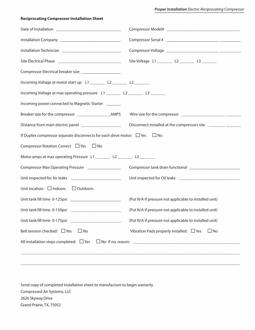
Reciprocating Compressor Installation Sheet
Date of Installation _______________________________ Compressor Model# ___________________________________
Installation Company _____________________________ Compressor Serial # _________________________ __________
Installation Technician ____________________________ Compressor Voltage _________________________ __________
Site Electrical Phase ______________________________ Site Voltage L1 _______ L2 _______ L3 _______
Compressor Electrical breaker size ___________________
Incoming Voltage at motor start up L1 _______ L2 _______ L3 _______
Incoming Voltage at max operating pressure L1 _______ L2 _______ L3 _______
Incoming power connected to Magnetic Starter _______
Breaker size for the compressor ________________AMPS Wire size for the compressor _____________________ _______
Distance from main electric panel ___________________ Disconnect installed at the compressors site ________ _______
If Duplex compressor separate disconnects for each drive motor: N Yes N No
Compressor Rotation Correct N Yes N No
Motor amps at max operating Pressure L1 _______ L2 _______ L3 _______
Compressor Max Operating Pressure ________________ Compressor tank drain functional ________________________
Unit inspected for Air leaks ________________________ Unit inspected for Oil leaks _____________________________
Unit location: N Indoors N Outdoors
Unit tank fill time 0-125psi ________________________ (Put N/A if pressure not applicable to installed unit)
Unit tank fill time 0-150psi ________________________ (Put N/A if pressure not applicable to installed unit)
Unit tank fill time 0-175psi ________________________ (Put N/A if pressure not applicable to installed unit)
Belt tension checked: N Yes N No Vibration Pads properly installed: N Yes N No
All installation steps completed: N Yes N No If no, reason: ___________________________________________________
_________________________________________________________________________________________________________
_________________________________________________________________________________________________________
Send copy of completed installation sheet to manufacture to begin warranty
Compressed Air Systems, LLC
2626 Skyway Drive
Grand Prairie, TX, 75052
Proper Installation Electric Reciprocating Compressor

Compressed Air Systems, LLC
2626 Skyway Drive
Grand Prairie, TX, 75052
1-800-531-9656
Fax 972-352-6364
Simplicity. It’s What We Do.