Electric Power From Ambient Energy Sources · 2007-03-13 · Electric Power from Ambient Energy...
59
PNNL-13336 Electric Power from Ambient Energy Sources John G. De Steese Donald J. Hammerstrom Lawrence A. Schienbein September 2000 Prepared for the U.S. Department of Energy under Contract DE-AC06-76RL01830
Transcript of Electric Power From Ambient Energy Sources · 2007-03-13 · Electric Power from Ambient Energy...
PNNL-13336
Electric Power from Ambient Energy Sources
John G. De Steese Donald J. Hammerstrom Lawrence A. Schienbein September 2000 Prepared for the U.S. Department of Energy under Contract DE-AC06-76RL01830

DISCLAIMER
This report was prepared as an account of work sponsored by an agency of the United States Government. Neither the United States Government nor any agency thereof, nor Battelle Memorial Institute, nor any of their employees, makes any warranty, express or implied, or assumes any legal liability or responsibility for the accuracy, completeness, or usefulness of any information, apparatus, product, or process disclosed, or represents that its use would not infringe privately owned rights. Reference herein to any specific commercial product, process, or service by trade name, trademark, manufacturer, or otherwise does not necessarily constitute or imply its endorsement, recommendation, or favoring by the United States Government or any agency thereof, or Battelle Memorial Institute. The views and opinions of authors expressed herein do not necessarily state or reflect those of the United States Government or any agency thereof.
PACIFIC NORTHWEST NATIONAL LABORATORY operated by BATTELLE
for the UNITED STATES DEPARTMENT OF ENERGY
under Contract DE-AC06-76RL01830
Printed in the United States of America
Available to DOE and DOE contractors from the Office of Scientific and Technical Information,
P.O. Box 62, Oak Ridge, TN 37831-0062; ph: (865) 576-8401 fax: (865) 576-5728
email: [email protected]
Available to the public from the National Technical Information Service, U.S. Department of Commerce, 5285 Port Royal Rd., Springfield, VA 22161
ph: (800) 553-6847 fax: (703) 605-6900
email: [email protected] online ordering: http://www.ntis.gov/ordering.htm
This document was printed on recycled paper.
(8/00)
PNNL-13336
Electric Power from Ambient Energy Sources John G. De Steese Donald J. Hammerstrom(a) Lawrence A. Schienbein(b) September 2000 Prepared for the U.S. Department of Energy under Contract DE-AC06-76RLO 1830 Pacific Northwest National Laboratory Richland, Washington 99352
_______________
(a)Hammerstrom Energy Applications and Technologies, Richland, Washington (b)CWT Technologies, Inc., Richland, Washington

iii
SUMMARY This report summarizes research on opportunities to produce electric power from ambient sources as an alternative to using portable battery packs or hydrocarbon-fueled systems in remote areas. The work was an activity in the Advanced Concepts Project conducted by Pacific Northwest National Laboratory (PNNL)a for the Office of Research and Development in the U.S. Department of Energy Office of Nonproliferation and National Security. PNNL evaluated the general feasibility and performance of several ambient energy conversion concepts and variants within each concept. The feasibility assessment of each concept class included designing baseline configurations governed by the principal boundary conditions of each case, including a 20-kg weight limit to satisfy the portability requirement. Basic performance levels were estimated for each concept including power, specific power and energy, and, where appropriate, daily energy capture. Several novel concepts were investigated in addition to conventional options. The following summarizes the general range of electric output power potential of the ambient energy concepts considered: • antenna capture of broadcast radio energy: microwatts to hundreds of milliwatts • power from transmission lines: tens of microwatts to several kilowatts • solar/photovoltaic (PV) battery charger: hundreds of milliwatts to about 10 W • small wind turbines: tens to hundreds of watts • small hydroelectric turbines: watts to hundreds of watts • thermal storage battery/direct conversion: watts to hundreds of watts • human energy conversion - cranked generator: up to about 300 W - mechanical spring: hundreds of microwatts daily average, tens of watts
short-term pulse power - power derived from walking: hundreds of milliwatts to about 20 W.
a Operated for the U.S. Department of Energy by Battelle Memorial Institute under Contract DE-AC06-76RLO 1830.

iv
Specific concept designs were developed at power levels within the above ranges. Table S1 summarizes the power, daily energy capture, specific power and energy density (based on daily energy conversion) of the best designs evaluated in each class.
Table S1. Performance Summary of Evaluated Concepts
Concept Power (W) Daily Energy Capture (Wh)
Specific Power (W/kg)
Energy Density (Wh/kg)
AM antenna at 1 km 0.2 4 0.8 16
Power line induction 113 740 5 37
Power line contact 3000 70,000 1000 23,333
Solar/PV battery (unconcentrated)
0.5 2.7 3.7 20
Solar/PV battery (concentrated)
7 40 7 40
Solar/thermal storage battery (TSB)/heat engine
225 5400 11 270
Improved wind turbine 100 720 25 180
Water turbine 100 2400 10 240
Hand-crank generator 100 430 53 227
Hand-wound spring 55 (pulse) - 110 (pulse) 0.03
Piezoelectric footwear 5 40 30 240
Footwear with electromechanical device
20 160 33 270
Seven of the concepts generally satisfy one or more levels of the power requirements specified by the U. S. Special Operations Command. Most of the concepts appear feasible with current or near-term technology. For example, the wind turbine class considered in the study is generally similar to several that are commercially available. Future realization of the currently anticipated performance of lithium polymer batteries was assumed in all options that store ambient energy electrically.

v
A novel thermal storage battery (TSB) concept was evaluated in which solar energy is stored thermally and re-radiated from surfaces with emissivity controlled by microelectromechanical systems (MEMS) technology. This thermal accumulator is envisioned as a common plug-in heat source for thermoelectric, thermionic or thermophotovoltaic converter arrays and is also adaptable to miniature Brayton, Rankine and Stirling engines and alkali metal thermal electric devices. Energy derived from human activity appears to be the most underutilized ambient energy resource. Humans are capable of operating machines (e.g., cranks, levers, springs, etc.) to generate power in the range from a few milliwatts up to more than 500 W. The upper end of this range corresponds to short duration athletic performance. However, persons of average size and fitness would be capable of generating several electrical watts with essentially unconscious effort by activating miniature electromechanical machines built into footwear. This study concludes that a number of currently underdeveloped or overlooked ideas and options exist that can provide new sources of portable power for remote-area missions. The possibility of total dependence on ambient energy could remove mission constraints imposed by the limited life and reliability of conventional batteries and the logistics of fuel supply. Ambient energy scavenging can also provide a means of stretching the mission life of conventional power systems used in remote areas. Defense and national security applications are expected to be among the first to justify the expected higher cost of exploiting ambient energy. Such developments can establish feasibility and initiate device improvement and cost reduction practices that lead to products of this type being introduced into the civilian marketplace. The concepts considered in this work could lead to derivative products that have many applications in areas such as transportation, renewable energy use, law-enforcement, outdoor recreation, and a variety of autonomous condition-sensing and monitoring systems.

vi

vii
CONTENTS SUMMARY................................................................................................................................... iii INTRODUCTION......................................................................................................................... 1 STUDY APPROACH AND PRIMARY ASSUMPTIONS ........................................................... 3 POWER RANGE............................................................................................................... 3 ENERGY STORAGE ........................................................................................................ 3 PORTABILITY................................................................................................................... 4 DEVICES POWERED BY BROADCAST ENERGY AND ELECTRIC POWER TRANSMISSION .......................................................................................................................... 5 AMBIENT ENERGY FROM BROADCAST RADIO........................................................ 5 ENERGY CAPTURE FROM ELECTRIC POWER LINES ............................................... 6 Capacitive Coupling................................................................................................. 6 Inductive Coupling ................................................................................................... 7 Direct Contact ......................................................................................................... 8 DEVICES POWERED BY THE SUN, WIND AND HYDROPOWER ......................................... 9 SOLAR-PHOTOVOLTAIC ENERGY CONVERSION.................................................... 9 Hand-Held Battery Charger ..................................................................................... 9 Battery Charger with Solar Flux Concentration....................................................... 10 Conventional Fuel Extender.................................................................................... 10 SOLAR HEATED THERMAL STORAGE BATTERY..................................................... 10 Low Power Thermoelectric Device......................................................................... 12 Low Power Stirling Device..................................................................................... 12

viii
TSB Economy of Scale .......................................................................................... 13 WIND POWER................................................................................................................ 13 Adaption of a Commercial Wind Turbine................................................................ 13 Reduced Scale HAWT.......................................................................................... 14 Vertical Axis Wind Turbine (VAWT) or Cross-Flow Wind Turbine ........................ 15 Thrust Loads and Tower Design............................................................................. 15 Kite Supported Operation...................................................................................... 16 PORTABLE HYDROPOWER ......................................................................................... 17 TURBINE SUMMARY.................................................................................................... 18 DEVICES POWERED BY HUMAN ACTIVITIES...................................................................... 21 LIMB-CRANKED GENERATORS ................................................................................. 21 Bicycle Byproduct Power....................................................................................... 21 Concept Performance Range.................................................................................. 22 Integration with Energy Storage .............................................................................. 23 MECHANICAL STORED ENERGY DEVICES.............................................................. 23 POWER PRODUCTION FROM WALKING................................................................. 24 Piezoelectric Generators......................................................................................... 25 Miniature Magnetohydrodynamic Generators.......................................................... 26 Miniature Electromagnetic Generators..................................................................... 26 Overall Perspective ................................................................................................ 27 CONCLUSIONS ......................................................................................................................... 29 REFERENCES ............................................................................................................................. 31

ix
APPENDIX A WIND TURBINE DATA................................................................................... A.1 APPENDIX B ELECTRIC POWER GENERATED BY WALKING........................................ B.1

x
LIST OF TABLES S1. Performance Summary of Evaluated Concepts........................................................................... iv 1. General Range of SOCOM Power Requirements ....................................................................... 3 2. Power Extracted from Broadcast Radio...................................................................................... 5 3. Comparison of Energy Storage Densities ................................................................................... 11 4. AIR Wind Turbine Performance................................................................................................ 14 5. Performance Summary of Evaluated Turbine Options................................................................. 18

1
INTRODUCTION Conventional electrochemical batteries or small hydrocarbon-fueled generators power many portable devices that require electric power in the field. Battery weight, life and reliability and the logistics of fuel resupply often limit the capabilities and range of such applications. Until recently, portable and remote-area applications were often too power and energy intensive, conservatively designed, and/or inflexible in their requirements to allow exploitation of ambient energy as a power source. However, advances in sensors and other electronic components appear to be continually reducing the power and energy requirements of many applications. If these requirements decline far enough, ambient energy conversion could become a viable source of power for many applications. The potential ability to satisfy all power and energy needs of an application using ambient energy could virtually eliminate mission constraints associated with conventional portable power supplies. Even at lower levels of dependence, ambient energy scavenging could stretch the performance and life of these devices. These possibilities suggest that it is worthwhile to re-examine the usefulness of ambient energy as a source of portable power. Ambient energy sources, including wind, geothermal heat and flowing water and radiation from the sun, have been exploited for power production since ancient times. All are established means of producing electricity in fixed-site facilities. In contrast, relatively little use has been made of these resources in portable power devices. Other forms of energy such as broadcast radio and television, microwave communications and electromagnetic fields of electric power lines add to the list of potentially useful energy sources. In addition, human presence or activities in the vicinity of applications represent another underutilized potential for generating electric power. This report summarizes efforts performed by Pacific Northwest National Laboratory (PNNL) and motivated by the above considerations to explore the general feasibility and achievable performance of devices that extract useful power from ambient energy sources. Oak Ridge National Laboratory (ORNL) completed a very useful and comprehensive survey entitled "Compact Portable Electric Power Sources" that became available before the conclusion of the PNNL study (Fry et al. 1997). The ORNL report complements this study and is referenced extensively in this report both to confirm the general feasibility and performance of the concepts PNNL evaluated and to identify areas where conclusions differ.

2
Intentionally blank

3
STUDY APPROACH AND PRIMARY ASSUMPTIONS A principal goal in the evaluation of ambient energy conversion was to focus on invention opportunities that enhance existing options or enable concepts previously overlooked or discarded. This approach emphasized searching for novelty over performing a thorough assessment of prior art. POWER RANGE Ambient energy concepts were evaluated with the potential of producing a useful output over a broad range of power from microwatts to kilowatts. However, the more viable and interesting options were found to perform in the narrower range of a few watts to several hundred watts. The power levels considered address remote, portable power applications of various government agencies including the non-proliferation treaty verification and multi-agency, civilian and military intelligence communities. In addition, some of the concepts considered potentially satisfy power requirements of the U. S. Special Operations Command (SOCOM), as indicated in Table 1 from Fry et al. (1997).
Table 1. General Range of SOCOM Power Requirements
Power Range (W) Energy Requirements (Wh)
Mission Length (days)
Total Energy (Wh)
0 to 50 100 30 3000
0 to 100 200 7 1400
0 to 300 1667 3 5000
1 to 1000 - - 8000
The successful use of ambient energy in defense and national security applications can lead to similar products being introduced into the civilian marketplace. The concepts considered may, therefore, also find application in areas such as transportation, renewable energy use, law-enforcement, outdoor recreation, and bio-engineering. ENERGY STORAGE Although a basic premise of this study is to relieve remote missions from the limitations of battery power, ambient energy capture and conversion are primarily means of opportunistically recharging rather than eliminating batteries entirely. Most applications will still require electric storage batteries to provide on-demand power together with optimal management of energy captured from sources with variable and/or intermittent intensity, such as the sun and wind. Therefore, with the notable exceptions of the thermal storage battery and hydropower, most of the concepts evaluated incorporate performance characteristics of a generic lithium battery that can be expected to evolve over the next 2 to 5 years from research and development efforts already underway.

4
For applications requiring electric energy storage, this study assumes that evolving technology will produce an affordable and reliable, long-life lithium battery with a specific energy of about 400 Wh/kg and a volumetric energy density of 800 kWh/m3. Fry et al. (1997) indicate an objective of current work on the lithium polymer battery is to achieve an energy density of 200 Wh/kg for automotive applications. Recent PNNL advances in vacuum depositing the layered structure of this battery point to the potential of exceeding this goal by a factor of two or more. Therefore, it is likely that one or more of the lithium batteries currently under development will ultimately reach the performance levels assumed in this study. PORTABILITY A general condition observed in the PNNL study was that portability implies a weight limit of 20 kg. While this is half of the 40-kg limit observed by Fry et al. (1997), it reflects consideration that a portable power supply will be generally only part of the load an individual would be required to carry. Most concepts evaluated in the PNNL study satisfy the lower portability requirement, generally by a large margin. However, none of the concepts was optimized either in performance or for specific applications. The more generous 40-kg limit could, therefore, allow a considerable increase in performance of some concepts. The potential of three general classes of device powered by ambient energy are summarized in the following sections. The first category is energy available in electromagnetic fields associated with broadcast media and electric power transmission. Sources in the second category include solar and wind energy and hydropower. The third category is energy that can be derived from human activities.
5
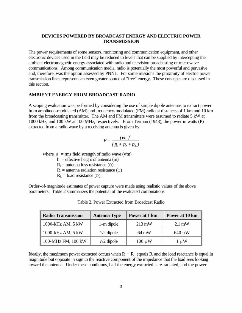
DEVICES POWERED BY BROADCAST ENERGY AND ELECTRIC POWER TRANSMISSION The power requirements of some sensors, monitoring and communication equipment, and other electronic devices used in the field may be reduced to levels that can be supplied by intercepting the ambient electromagnetic energy associated with radio and television broadcasting or microwave communications. Among communication media, radio is potentially the most powerful and pervasive and, therefore, was the option assessed by PNNL. For some missions the proximity of electric power transmission lines represents an even greater source of "free" energy. These concepts are discussed in this section. AMBIENT ENERGY FROM BROADCAST RADIO A scoping evaluation was performed by considering the use of simple dipole antennas to extract power from amplitude-modulated (AM) and frequency-modulated (FM) radio at distances of 1 km and 10 km from the broadcasting transmitter. The AM and FM transmitters were assumed to radiate 5 kW at 1000 kHz, and 100 kW at 100 MHz, respectively. From Terman (1943), the power in watts (P) extracted from a radio wave by a receiving antenna is given by:
where ε = rms field strength of radio wave (v/m) h = effective height of antenna (m) Rl = antenna loss resistance (O) Rr = antenna radiation resistance (O) RL = load resistance (O). Order-of-magnitude estimates of power capture were made using realistic values of the above parameters. Table 2 summarizes the potential of the evaluated combinations.
Table 2. Power Extracted from Broadcast Radio
Radio Transmission Antenna Type Power at 1 km Power at 10 km
1000-kHz AM, 5 kW 1-m dipole 213 mW 2.1 mW
1000-kHz AM, 5 kW ?/2 dipole 64 mW 640 µW
100-MHz FM, 100 kW ?/2 dipole 100 µW 1 µW
Ideally, the maximum power extracted occurs when Rl + RL equals Rr and the load reactance is equal in magnitude but opposite in sign to the reactive component of the impedance that the load sees looking toward the antenna. Under these conditions, half the energy extracted is re-radiated, and the power
)R+R+R(
)h(=P
Lrl
2ε

6
dissipated by Rl and RL is (εh)2/4Rr. In practice, it is difficult to operate at this design point. A 1-m dipole is physically small compared to the AM broadcast wavelength of 300 m. This results in its radiation resistance being only a few µO. Therefore, it is difficult to make Rl and RL low enough to obtain efficient power extraction and at the same time supply significant power to a load. However, the 1-m dipole performs better than the half-wavelength dipole, which is not only more conspicuous but also introduces a much larger Rl term. The 3-m wavelength of the FM transmission allows the ?/2 dipole to be somewhat better than the equally practical 1-m dipole. However, the small physical size of both antennas is associated with a much larger Rr, which reduces the energy capture potential of this option below that of the AM case. Fry et al. (1997) reference work performed by Norton, an ORNL colleague, who has proposed an automated means of extracting power from the strongest amplitude-modulated radio (AM) signal in the vicinity. The ORNL report indicates the range of available power from this source is microwatts to hundreds of milliwatts depending on distance and power of the transmitter. As shown in Table 2, the PNNL evaluation is consistent with this ORNL conclusion. The concept may be capable of better performance with innovations in antenna design that were not evaluated in this study and where applications allow operation much nearer to the transmitter. Energy scavenged from radio transmission would have a relatively high capacity factor because many stations broadcast from 14 to 24 hours a day. ENERGY CAPTURE FROM ELECTRIC POWER LINES Energy capture from power distribution and transmission lines was not treated in the ORNL report. However, three potential classes of opportunity in this category were evaluated by PNNL, as noted below. Capacitive Coupling An antenna insulated from ground and stretched between adjacent poles or towers of a transmission line could act as the plate of a capacitor. When charged by its proximity to the overhead conductors of the transmission system, the antenna would act as a synchronous voltage generator that could be used to energize a low-power application. The geometry investigated was a 50-m long antenna stretched between towers at a height of 6 m above the ground and 6 m below a typical three-phase, 345-kV overhead transmission system consisting of three conductors spaced 7 m apart. Analysis showed that this concept would generate only about 10 µW when supplying a properly-tuned load impedance. About a kilogram of materials and tools would be necessary, giving the concept an insignificant specific power of 10 µW/kg. This does not appear to warrant further consideration.

7
Inductive Coupling Potentially more power can be tapped by electromagnetic induction. The configuration evaluated consists of insulated copper wires that run for some distance parallel to and on both sides of a transmission system right-of-way. The wires are connected at each end by conductors that cross under the transmission lines forming a loop. Electromagnetic induction occurs in the portions of the loop that are asymmetrical with respect to the geometry of the three-conductor overhead system. Very little voltage is induced in the parts of the loop directly under the overhead conductors. The concept could be realized by mounting a wire fence on insulation provided by wooden poles along each side of the transmission route. Such fences are often found already in place to prevent public access to the right-of-way. The ends of each active fence section would be linked by insulated conductors. Multiple wires on each pole could be connected to form a multi-turn array. An alternative and less conspicuous approach would be to bury an insulated wire loop in a shallow trench and back fill. The energy capture potential of this concept was evaluated by considering a loop with an active length of 50 m on the sides running parallel to the transmission line. As before, the reference transmission system is a three-phase, 345-kV overhead transmission system consisting of three conductors spaced 7 m apart and 12 m above the ground. The long parallel sides of the loop are 7 m further outside the outer transmission conductors. Total loop length of this configuration is 156 m. The concept is, in essence, a transformer in which the transmission conductors are each single primary turns and the ground-level loop is the secondary winding linked by magnetic flux across a very large air core. The power capture of this concept is proportional to the number of turns in the secondary loop. Therefore, wire can be usefully deployed up to the portability limit of 20 kg. This weight limit allows nearly 700 m of 2.05-mm (12 AWG size), enamel-coated copper wire to be field deployed. Using this wire size as a working example, a four-turn loop leaves enough extra wire to provide current leads to an application located over 30 m distant from the edge of the transmission right-of-way. Power output of the concept was estimated to range from about 2 W to 113 W corresponding to root mean square (rms) phase currents in the overhead conductors of 100 A and 800 A, respectively. An 800-A rms phase current represents operation of a 345-kV transmission system at about 95% of its typical 500-MW transfer capacity. The balance of equipment needed to deploy this concept, including a wire reel, small trenching tool and power conditioning package should contribute less than about 2 kg of additional weight. Therefore, at the higher output level, the specific power is in excess of 5 W/kg. Output of the secondary coil would fluctuate as changes in transmission line loading occur. If the transmission system operates at a 50% or higher load factor, the wire loop secondary can deliver at least 740 Wh/day. This simple device should be difficult to detect remotely and would be amenable to further optimization when the operational characteristics of the transmission system in a specific field location are known.

8
Direct Contact If the remote power application is already close enough to a distribution or transmission line to make considering the above option worthwhile, then far more power could be tapped by direct contact. Electric utility workers repair energized lines using long, insulated manipulators known as "hot sticks." While many utilities limit their use to system voltages up to 230 kV, others allow work at 500 kV and above with these devices. Using hot sticks is considered an art, and a dangerous one. However, hot sticks can conceivable be made "smart" by equipping them with sensors and protective devices that would allow deployment only when voltage and other ambient conditions are safe. A smart "hot stick" built for this purpose could include dropping and/or voltage-dividing resistors to limit the amount of power "leaked" from the system to match the requirements of the application. Alternatively, an inductive loop could be remotely deployed around one of the transmission or distribution system conductors. Both concepts would use a reel-type device to dispense a flexible, insulated cable that carries the active electrical elements. This cable would be shot upwards from the ground and attached to the overhead conductor by a spring-activated hook or loop. Disengagement of the attachment mechanism might be achieved by electrically activating filaments of shape-memory material to detach the hook or unwind the loop at the end of the mission. Such devices could be used to tap power from transmission lines in quantities limited only by the resolution of system protective and metering equipment. Power loss metering typically is limited to 0.3% resolution. This means, for example, that 3 kW could be extracted from nothing larger than a 1-MW electric distribution feeder without detection by central dispatch or substation metering. The smart "hot stick" could conceivably be packaged in a cylinder 10 cm in diameter and 1 m long, with a mass of between 3 and 4 kg. The example evaluated indicates a specific power in the range of 750 to 1000 W/kg and an energy capture potential of more than 70,000 Wh/day. This level of power scavenging exceeds the highest range of SOCOM power requirements by a large margin. The need for remote operations in the vicinity of electric power distribution and transmission systems is likely to be very infrequent. However, when this coincidence occurs, electric power systems can be tapped to provide more ambient energy than is conveniently available by any other means.

9
DEVICES POWERED BY THE SUN, WIND AND HYDROPOWER The most pervasive, although intermittent, sources of useful ambient energy are solar and wind energy. Where available, flowing water is also a potential resource for energizing portable electric generators. The variability of solar and wind energy is expressed as the capacity factor of the converter. This represents the percentage of time solar- or wind-energized equipment operates at rated power. Systems that convert solar radiation to electric power typically exhibit a capacity factor of 25% compared to an upper bound of about 30% for wind-powered systems. In contrast, a portable generator in a flowing stream or river could have a year-round capacity factor approaching 100%, as limited by the availability of the equipment rather than that of the energy resource. The referenced ORNL report accounts for all three of the above technologies (Fry et al. 1997). PNNL evaluated concepts in these categories to establish the general performance characteristics of complete systems and, in some cases, their development potential, as described in this section. An additional concept discussed is a solar-heated thermal storage battery that incorporates microelectromechanical systems (MEMS) technology for thermal management and electric power control. SOLAR-PHOTOVOLTAIC ENERGY CONVERSION Commercially available, solar-energized photovoltaic cells and modules imbed technology that has been developed over the last 30 years. Fry et al. report that the military used portable, book-sized solar cell kits to recharge batteries in the field during the 1991 Gulf War with Iraq. Acknowledging the extensive technology base, prior art in device design and current availability of PV systems, PNNL designed and evaluated three solar-PV devices to benchmark overall performance characteristics of small portable systems. Hand-Held Battery Charger The hand-held battery charger, relying on unconcentrated solar flux, has dimensions similar to those of a typical solar-powered electronic calculator (15 cm x 7 cm x 1.5 cm). The device accommodates a solar cell area of about 20 cm2 and a lithium polymer battery with between 3 and 10 Wh of capacity, depending on the application. The dimensions of the device would also accommodate miniature sensors and/or electronics for data storage, processing and communication or alternatively more battery capacity (>100 Wh), which would allow a charge/discharge capability for many days. In the 10-Wh configuration, the package would weigh 140 g. Performance of the concept is estimated at a peak solar flux energy intensity of 0.1 W/cm2. Other principal assumptions include a PV cell energy conversion efficiency of 25%, 25% capacity factor accounting for the diurnal variability of solar energy and a 90% round-trip battery charging efficiency. On this basis, peak electric power supplied to the battery is 500 mW and daily energy storage would be about 2.7 Wh. As limited by the daily charge, the energy density of the system is nearly 20 Wh/kg. However, energy densities up to an order of magnitude larger are possible with a larger PV cell area and/or a larger battery charged over many days.

10
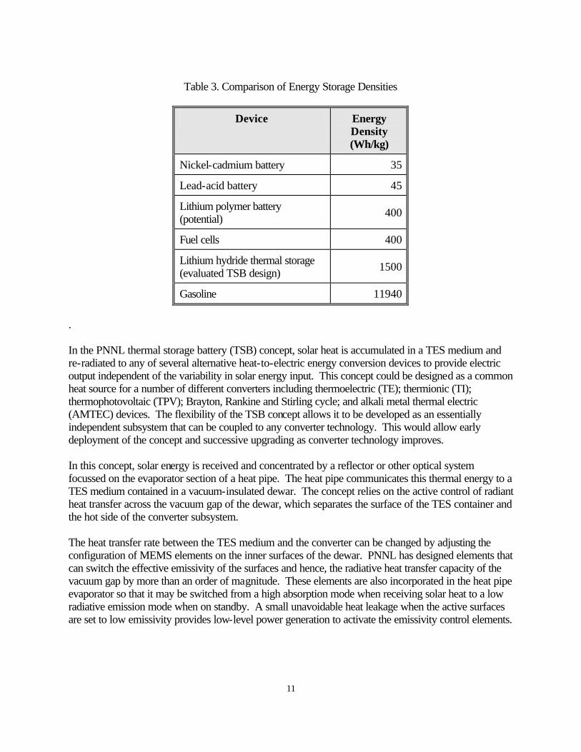
Battery Charger with Solar Flux Concentration With solar flux concentrated to the 1 W/cm2 level, at a concentrator efficiency of 30% and PV cell area of 100 cm2, the above concept increases its peak electrical output to 7 W in a package weighing about a kilogram. Assuming, as before, a 25% capacity factor and a 90% round-trip battery charging efficiency, the concept will store approximately 40 Wh/day and achieve a specific energy of 40 Wh/kg. As with the smaller unit, this system will accept a larger battery for longer term charge/discharge capability. Conventional Fuel Extender In research outside of this project, PNNL evaluated a MEMS-based portable fuel cell system to provide 5 W of base-load electric power generation with the capability of supplying 10-W peak demands in a possible SOCOM-type mission environment. The 1-kg system would use a liquid hydrocarbon fuel augmented by solar energy. Working at the design electrical output level of 145 Wh/day, the hydrocarbon fuel supply would last for about 7 days in the field before requiring resupply. Solar energy would provide a means of extending the mission duration of such a fuel cell system. Assuming a conservative PV power conversion efficiency of 15%, deployable square arrays of PV cells with dimensions between 40 cm by 40 cm and 1.2 m by 1.2 m could provide up to about 75% of the mission's daily energy requirement, as determined by the quality of the solar day, latitude and season. Depending on availability, solar energy could stretch the in-field adequacy of the nominally 1-week hydrogen supply to between 2 and 4 weeks. This example illustrates the value of considering ambient energy scavenging as an adjunct to conventionally fueled systems. SOLAR HEATED THERMAL STORAGE BATTERY Storing solar energy in a thermal energy storage (TES) medium with conversion of heat to electricity on demand is a possible alternative to the PV/electric battery concepts considered above. The incentive for considering TES media is that energy storage densities can be many times larger than those of electric batteries and only an order of magnitude less than hydrocarbon fuels, as illustrated in Table 3. This section summarizes a concept investigated at PNNL that uses developing MEMS technology to provide thermal and electrical control of the device.
11
Table 3. Comparison of Energy Storage Densities
Device Energy Density (Wh/kg)
Nickel-cadmium battery 35
Lead-acid battery 45
Lithium polymer battery (potential) 400
Fuel cells 400
Lithium hydride thermal storage (evaluated TSB design) 1500
Gasoline 11940
. In the PNNL thermal storage battery (TSB) concept, solar heat is accumulated in a TES medium and re-radiated to any of several alternative heat-to-electric energy conversion devices to provide electric output independent of the variability in solar energy input. This concept could be designed as a common heat source for a number of different converters including thermoelectric (TE); thermionic (TI); thermophotovoltaic (TPV); Brayton, Rankine and Stirling cycle; and alkali metal thermal electric (AMTEC) devices. The flexibility of the TSB concept allows it to be developed as an essentially independent subsystem that can be coupled to any converter technology. This would allow early deployment of the concept and successive upgrading as converter technology improves. In this concept, solar energy is received and concentrated by a reflector or other optical system focussed on the evaporator section of a heat pipe. The heat pipe communicates this thermal energy to a TES medium contained in a vacuum-insulated dewar. The concept relies on the active control of radiant heat transfer across the vacuum gap of the dewar, which separates the surface of the TES container and the hot side of the converter subsystem. The heat transfer rate between the TES medium and the converter can be changed by adjusting the configuration of MEMS elements on the inner surfaces of the dewar. PNNL has designed elements that can switch the effective emissivity of the surfaces and hence, the radiative heat transfer capacity of the vacuum gap by more than an order of magnitude. These elements are also incorporated in the heat pipe evaporator so that it may be switched from a high absorption mode when receiving solar heat to a low radiative emission mode when on standby. A small unavoidable heat leakage when the active surfaces are set to low emissivity provides low-level power generation to activate the emissivity control elements.

12
As the TSB concept is coupled to a thermal engine of some kind, system performance is maximized by storing thermal energy at the highest practical temperature. A basic consideration is how high a temperature can be sustained by the solar concentrator system. With a 10:1 solar flux concentration (to 1 W/cm2), the evaporator end of a heat pipe having an emissivity of 0.1 can reach 1160 K before it re-radiates heat at the same surface flux density, i.e., it would lose heat at the same rate heat is received. Other heat leakage elsewhere in the system would reduce the maximum achievable temperature somewhat. For the purpose of exploring the potential of the concept, the scoping evaluation was based on the selection of lithium hydride (LiH) operating over the temperature range 700 to 1100 K around its 962 K melting point. As shown in Table 3, a thermal energy storage density of 1500 W/kg is achieved from the combined heat of fusion and specific heat of LiH over this range. The performance of three TSB combinations was evaluated as discussed below. Low Power Thermoelectric Device The TSB could be demonstrated using today's off-the-shelf TE elements with a net thermal-to-electric efficiency of about 5%. With a density of 1000 kg/m3, a kilogram of LiH occupies 1000 cm3 or approximately a 10-cm cube. The required solar flux would be concentrated over a 12-hour collection period by a foldable parabolic reflector with 30% collection efficiency and a deployed area of 4340 cm2 (75-cm diameter). Allowing an appropriate expansion volume in the LiH container, a stray heat loss of 10% and 95% electric power conditioning efficiency, this TSB/TE combination would deliver an average daily power output of 3 W in a 2-kg package, thereby providing a specific power and energy density of 1.5 W/kg and 36 Wh/kg, respectively. While these are not spectacular performance levels, activation of the MEMS elements could increase the radiative power transfer of the output dewar subsystem and could provide the device with a short-time high power of up to 70 W. A larger solar concentrator would be required to maintain the energy balance in this mode of operation. Low Power Stirling Device Stirling engine technology has been developed over several decades for use in remote power applications. Packaged, miniature Stirling systems with electrical output in the 10-W to 3000-W range, are approaching availability (White et al. 1996). A Stirling engine fitted with an integral linear alternator appears to be intrinsically well suited as the energy converter subsystem in a TSB. Using the same TES package and solar energy collector as above, a TSB-Stirling system with a mass of 4 kg was estimated to produce 10 W with an overall conversion efficiency of approximately 17%. The corresponding power and energy densities associated with the average daily energy balance would be 2.5 W/kg and 60 Wh/kg, respectively. With appropriate increases in capability of the Stirling engine and linear alternator, the MEMS-regulated emissivity device could support a short-time peak output of over 200 W.

13
TSB Economy of Scale A final evaluation of the TSB concept involved consideration of its growth potential and performance at the 20-kg portability limit. The analysis assumed the development of a 25% efficient converter with a 500 W/kg specific power. Fry et al. (1997) projected the AMTEC concept as being capable of this performance in the near term. The TSB design at these levels of performance includes a solar concentrator 3 m in diameter and 15 kg of LiH thermal storage medium. Assuming, as before, 10% thermal energy leakage, and solar collector and power conditioning efficiencies of 30% and 95%, respectively, a 20-kg TSB-AMTEC combination could provide an average daily electrical output of 225 W. The corresponding specific power and energy density are 11 W/kg and 270 Wh/kg. A MEMS-regulated peak output of about 670 W could be supported for about 8 hours following achievement of a full thermal energy charge. It is recognized that this concept inherently would have a strong infrared signature, which would limit its deployment to special opportunities where this disadvantage is less important. However, its potential for remote or automatic thermal and electrical regulation provided by MEMS elements and its use as a common heat source for several different heat engine systems remain attractive features. Within the assumed 20-kg portability limit, the concept could satisfy all but the 1000-W range of the SOCOM power requirements shown in Table 1. WIND POWER Reliance on wind-generated mechanical and electrical power was widespread in U. S. in the days before rural electrification. Fry et al. (1997) note that a present-day market exists for small wind turbines to supply a number of remote power requirements including military bases, vacation homes, irrigation and navigation aids. This experience suggests that modern wind turbine technology combined with innovation may provide viable portable wind power options for field use. This concept demands, in general, that a wind turbine be compact, portable, and capable of easy field-assembly without a large number of tools. The PNNL study surveyed a number of commercially-available small wind turbines to evaluate how closely presently available equipment would satisfy these requirements. Consideration was given to both horizontal and vertical axis machines. Adaptation of a Commercial Wind Turbine It appears quite possible to adapt an existing, off-the-shelf horizontal axis wind turbine (HAWT) in the 0.5-m to 2-m rotor diameter range to meet more stringent weight and portability requirements. Based on a survey of several commercial turbines the Southwest Windpower AIR unit would be an ideal basis for such a machine (see Appendix A, Table A1). The AIR unit has a 1.14-m rotor diameter and a "tower top" weight of 6 kg.

14
The 1.14-m commercial AIR turbine's electrical output is shown in Table 4 as a function of wind speed. This performance appears reasonable based on a check of the equivalent efficiencies. For example, 100 W output at 10 m/s implies an overall efficiency of about 16%, which is quite reasonable for this type of machine.
Table 4. AIR Wind Turbine Performance
Wind Speed (m/s) Electrical Power Output (W)
4 0
10 100
11.6 200
12.5 300
The turbine's parts list is shown in Appendix A, Table A2. Appendix A also lists the additional parts and tools required for assembly in the field. The need for these extra parts and tools could be easily eliminated in a device designed to be portable. The mass of the machine could be reduced by measures indicated in Appendix A including removal of the nose cone, structural design and component consolidation or elimination. Essentially, the machine could be reduced to a tail-less, fixed yaw wind turbine, which would have an appearance similar to a child's plastic "spinner" toy. The turbine would consist of blades and a main body. The main body would be an integrated, preassembled part consisting of the generator (incorporating the bearings), rotor shaft, hub and a simple means of attaching to a pipe or extendible mast. Two-blades, or even one blade could be substituted as alternatives to the present three-blade design. Such a redesign is expected to remove at least 2 kg leaving a machine with a mass of about 4 kg. Reduced Scale HAWT A smaller but lower power HAWT could be designed with a target mass of 3 kg or less (about the mass of a lap-top computer). A turbine having a rotor diameter somewhat less than 1 m would meet this requirement. Assuming that the AIR unit follows the relationship between mass/swept area and rotor diameter of other turbine designs in this size range, a 0.5-m version of the AIR system would weigh about 2 kg. Of course, its energy capture and rating would decline by roughly 80% or more (because the Reynolds Number drops by about 70%). The rating of this device would fall to approximately 10 W at 10-m/s wind speed. The mass of an AIR unit with a 0.5-m rotor diameter was estimated from data available for the LVM series of turbines. This class of wind turbines appears to exhibit the characteristic of about 7 kg/m2 per meter of rotor diameter. Projecting this relationship to a unit with a 0.5-m rotor diameter confirms that this size of turbine would have a mass of about 2 kg.

15
A 1-m diameter turbine if equipped with conventional blades would force the maximum carrying package dimension to be about 500 mm (nearly 20 inches). However, the blades could be made to "break-down" into two pieces that might be "snapped" together, reducing the maximum dimension to about 250 mm. Inflatable blades may be feasible but it is not obvious that they would be able to handle the maximum out-of-plane bending and shear loads or would weigh less than well designed carbon fiber composite blades. Furthermore, simple blade braces could lead to an overall weight reduction for the turbine by permitting reduced blade wall thickness. Vertical Axis Wind Turbine (VAWT) or Cross-Flow Wind Turbine The vertical axis (VAWT) or cross-flow sail-bladed turbine invented by Lewis Feldman (1989) would be ideal as a very lightweight small machine. The performance of such a turbine should be about equal to that of a HAWT of the same swept area. Although originally aimed at very large utility-scale machines, the design approach devised by Feldman could be readily adapted to turbines having a swept area of about 1 m2. For ease of field assembly, the turbine's sails would roller-furl parallel to and flush with the central column, resulting in a furled shape looking much like a long umbrella. Spring-loaded furling drums or spools would be suitable in this application. The turbine would be spun into operation using a simple starting reel, similar to that used by many lawn mowers, to gain sufficient centrifugal force to activate the unfurling mechanism. The shaft could be further collapsed in length to a shape and size approximating that of a collapsible umbrella. Feldman's approach would require substantially more research and development work. However, the intrinsic ease and speed of assembly and disassembly (probably substantially better than any horizontal axis wind turbine approach that can be devised) could make the effort rewarding. Furthermore, the cross-flow approach eliminates the need for a yawing system and should operate more efficiently overall than a HAWT operating with fixed yaw, as described previously. Total turbine mass would probably not be less than for a horizontal axis type of the same swept area and rating. Nevertheless, it is important to note that the VAWT turbine is inherently equipped with the tower section necessary to bring the mounting point to just below the blade roots, while the HAWT would require an extra length of tower extending from the hub to the blade tip. Thrust Loads and Tower Design Thrust load on the rotor parallel to the flow direction is proportional to the square of the wind speed. If the turbine is designed to load shed, a thrust coefficient of unity can be assumed for design purposes. Assuming that the turbine is stopped or yawed out of the wind for wind speeds above 25 m/s, the design thrust load for a 1-m diameter HAWT (and tower) would be 300 N (about 67 lbf).

16
Cantilever support of a portable tower would appear to be impractical unless the tower could be clamped to an existing rigid structure. (A guy-supported pipe is usually used for this size of wind turbine.) Assuming that the small turbine will always be operated well clear of structures, trees and other obstacles, a tower height of only about 1.5 m could be quite satisfactory. In this case, a collapsible tripod tower similar to a camera tripod could be used. Furthermore, the design thrust load for the turbine and tower could be substantially reduced because the operator could quickly intervene to stop the turbine and dismantle the tower and turbine under extreme conditions. Kite Supported Operation As a alterative to using a field-erected tower or mast, a small wind turbine might be carried aloft by a kite. An additional advantage would be operation in regions of higher wind speed. As a first approximation for open treeless areas, wind speed is assumed to increase with height above ground proportional to the 1/7 power of altitude (the so-called "1/7 power law"). Increasing the turbine mounting height from 1.5 m to say 25 m results in wind speed being increased by a factor of about 1.5. For the same power output performance with reference to wind speed at 1.5 m, flying the turbine on a kite would permit the turbine diameter to be significantly decreased (e.g., from 1 m to about 0.5 m). An interesting and advantageous feature of kite support is the fact that the kite/wind turbine would automatically seek a new equilibrium position where higher wind speeds exist. The drag of the wind turbine should be taken into account as an additional equivalent drag coefficient based on the kite wing area. Simply suspending a 0.5-m diameter turbine beneath the kite would appear quite feasible (heavy load lifting kites have been demonstrated for more than a century). Maintaining the turbine axis parallel to the wind could be accomplished by using an additional line and bridle arrangement. Integrating the wind turbine with the kite wing structure is probably the preferred approach because it simplifies the assembly, launching and control of the system. Positioning the turbine rotor (or equivalent) in the plane of the wing or horizontal stabilizer opens up the possibility of using an oscillating wing turbine ("wing-mill") approach. This approach replaces the rotor with a system of translating and oscillating pitch blades. The size of kite required to successfully launch the turbine subsystem at relatively low wind speeds might be prohibitive. For example, launching a 2-kg turbine payload in a wind speed of 5 m/s near ground level could require a kite wing area of about 12 m2, assuming a wing lift coefficient of about 0.3 at launch and a kite mass of 0.3 kg/m2. The entire system mass would be about 5.6 kg, not including the mass of the line and bridle assembly for the turbine. System mass is highly sensitive to the launching speed. Continuing the previous example, increasing the minimum launch speed to 8 m/s (about 18 mph) decreases total kite wing area required to only 2.2 m2 and total system mass to 2.7 kg. A running launch in a 5 m/s wind speed might be able to provide an 8 m/s relative wind. Even assuming zero kite mass, the wing area required is still 1.7 m2, demonstrating that kite mass becomes far less important as launch speed increases. This example demonstrates

17
general feasibility; however, a full parametric study should be carried out to develop an approach that minimizes overall system mass to permit very low launch speeds and to meet portability requirements. PORTABLE HYDROPOWER A run-of-the-river turbine was considered where the turbine is designed to "fly" in the flow using a tethered line, much like a kite, except that slightly negative buoyancy will be required unless hydrodynamic lifting surfaces are used as depressors. The design of tethered water turbines is akin to that of underwater towed sonar bodies. At 15EC, the density of fresh water is about 820 times that of air. Assuming that flow rates of 1 m/s are reasonably accessible, an axial-flow water turbine with the same overall efficiency and rating as the AIR 1.14-m diameter wind turbine would have a rotor diameter of about 1.25 m. Assuming that the optimum tip speed to stream speed ratio is 10 and the rotor solidity is the same for both the wind turbine and the water turbine, the Reynolds number based on average blade chord will be very nearly equal. However, out-of-plane blade loads (and overall thrust load on the rotor) will be approximately 10 times greater for the water turbine suggesting substantially heavier blades and support structures, including the tethering cable. Such a system might weigh about 10 kg. Thrust loading for the 1.25-m water turbine was estimated to be about 600 N (135 lbf) at 1 m/s flow rate. A simple turbine having a rotor diameter of 100 mm and operating in water flowing at 1 m/s would have an electrical output of about 1 W. (It is important to note that the water turbine could operate at essentially a 100% capacity factor, while the wind turbine will probably operate with a capacity factor between 15 and 30% on an annual basis.) Axial thrust would be a very modest 4 N (about 1 lbf). The harness required for the axial type water turbine could be combined with a diffuser augmenter (or shroud) that could increase output by between 50 and 100%. The diffuser shape would probably greatly assist flow alignment and stability. Axial thrust would increase by about the same factor range. With careful design, a diffuser-equipped 100-mm diameter turbine operating in a 1-m/s stream flow could produce approximately 2 W in a device weighing 1 kg. Cross-flow (or "vertical-axis") water turbines have been the subject of considerable research and testing at the Canada National Research Council in the context of fairly large power output using arrays of vertically mounted turbines on cross-stream barges. For the portable application, the turbine could operate with the axis of rotation in any position, although some stabilizers may be required to prevent constant rotation of the turbine about the tether line axis. Cross-flow turbines with straight blades offer several advantages: • The blades are supported at two ends offering the possibility of reduced blade mass. • Attaching the turbine to a tethering line is straightforward when compared to the axial flow
turbine. • The turbine will reliably self-align with the stream-flow.
18
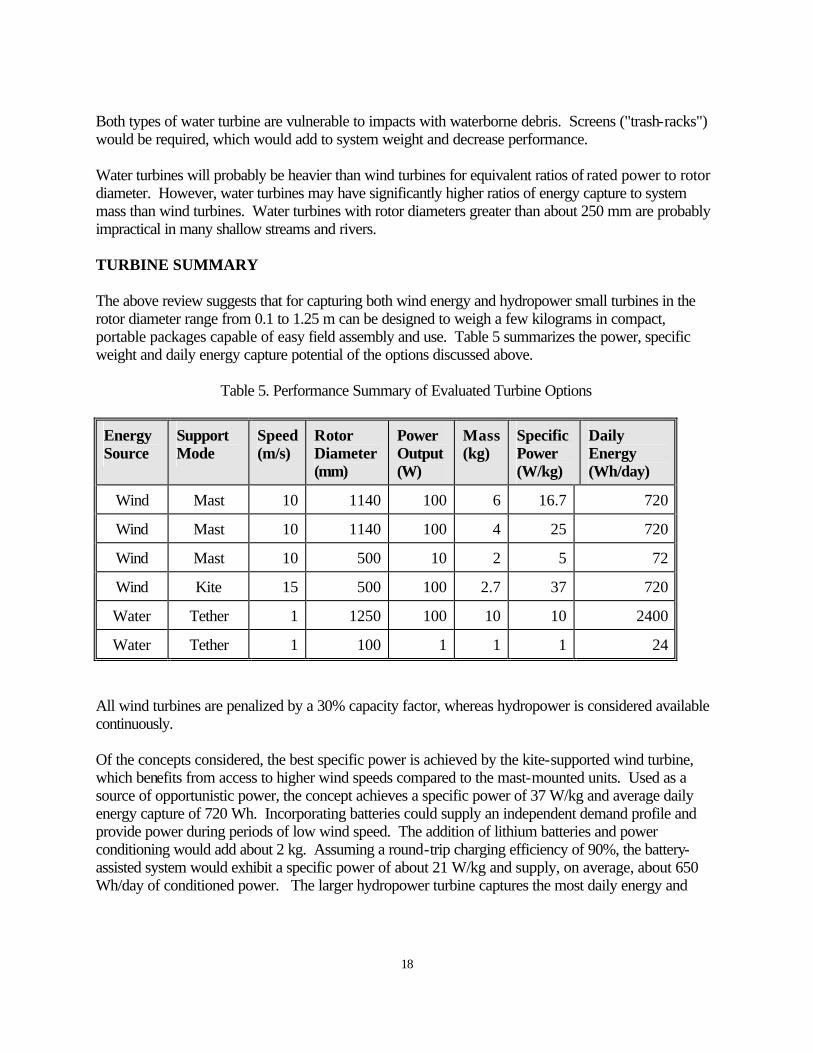
Both types of water turbine are vulnerable to impacts with waterborne debris. Screens ("trash-racks") would be required, which would add to system weight and decrease performance. Water turbines will probably be heavier than wind turbines for equivalent ratios of rated power to rotor diameter. However, water turbines may have significantly higher ratios of energy capture to system mass than wind turbines. Water turbines with rotor diameters greater than about 250 mm are probably impractical in many shallow streams and rivers. TURBINE SUMMARY The above review suggests that for capturing both wind energy and hydropower small turbines in the rotor diameter range from 0.1 to 1.25 m can be designed to weigh a few kilograms in compact, portable packages capable of easy field assembly and use. Table 5 summarizes the power, specific weight and daily energy capture potential of the options discussed above.
Table 5. Performance Summary of Evaluated Turbine Options
Energy Source
Support Mode
Speed (m/s)
Rotor Diameter (mm)
Power Output (W)
Mass (kg)
Specific Power (W/kg)
Daily Energy (Wh/day)
Wind Mast 10 1140 100 6 16.7 720
Wind Mast 10 1140 100 4 25 720
Wind Mast 10 500 10 2 5 72
Wind Kite 15 500 100 2.7 37 720
Water Tether 1 1250 100 10 10 2400
Water Tether 1 100 1 1 1 24
All wind turbines are penalized by a 30% capacity factor, whereas hydropower is considered available continuously. Of the concepts considered, the best specific power is achieved by the kite-supported wind turbine, which benefits from access to higher wind speeds compared to the mast-mounted units. Used as a source of opportunistic power, the concept achieves a specific power of 37 W/kg and average daily energy capture of 720 Wh. Incorporating batteries could supply an independent demand profile and provide power during periods of low wind speed. The addition of lithium batteries and power conditioning would add about 2 kg. Assuming a round-trip charging efficiency of 90%, the battery-assisted system would exhibit a specific power of about 21 W/kg and supply, on average, about 650 Wh/day of conditioned power. The larger hydropower turbine captures the most daily energy and

19
illustrates the economy of scale in turbine design where an order of magnitude increase in mass and principal dimensions allow two orders of magnitude increase in power. Hydropower is one concept that, as a result of its high daily availability, could be used without battery backup. The specific power and energy capture of the device are, therefore, essentially the same in the integrated system. All but the smallest mast-mounted wind turbine and the 100-mm water turbine satisfy SOCOM power requirements up to 100 W, as shown in Table 1.

20
Intentionally blank

21
DEVICES POWERED BY HUMAN ACTIVITIES Energy derived from human activity appears to be the most underutilized ambient energy source. Humans are capable of operating machines (e.g., cranks, levers, springs, etc.) to generate mechanical power ranging from a few milliwatts to more than 500 W. The upper end of this range corresponds to athletic performance and can be sustained for relatively short periods. Nevertheless, persons of average size and fitness are capable of generating useful levels of electrical power, which is the principal focus of this section. Other than scientific toys and novelty devices, few devices are marketed that make or use human-generated electric power. The ORNL report acknowledges the potential utility of hand-cranked generators to provide emergency backup power in the field (Fry et al. 1997). However, the time and energy taken from other duties to activate such a device is cited as a limitation of the concept. Less limiting, in principle, is the concept of incorporating miniature piezoelectric generators in boots that are powered by pressure generated during walking. Fry et al. cite an evaluation of this concept by Comprehensive Technologies International, Inc. and conclude that piezoelectric transducers produce too little power and cost too much to be worth further consideration. In PNNL's assessment, these concepts and variations thereof were considered from a fresh perspective leading to the conclusion that there is more potential opportunity for capturing human energy by these means than is indicated in the ORNL report. The human-energy devices evaluated in this study are discussed below. LIMB-CRANKED GENERATORS Generators cranked by hand or leg motion can supply on-demand power in situations where personnel are present in the vicinity of the application. The ORNL report indicated that, despite its limitations, the hand-cranked generator is a candidate for near-term development. A benchmark performance capability of the power-producing component of this concept is represented by characteristics of an axial-gap generator recently designed at ORNL. This device produces 500 W at an efficiency greater than 95% and weighs about 1 kilogram in a cylindrical package 9 cm in diameter and 5.7 cm long (Fry et al. 1997). Bicycle Byproduct Power Producing electrical power from a few watts to perhaps 20 W is a specific opportunity niche for exploiting human activity without requiring significant conscious effort and, therefore, interruption of other duties. For example, a normal individual riding a bicycle is comfortable at an exertion rate of about 0.1 hp (75 W). Riding a bicycle equipped with a small electric dynamo to power front and rear lights at night requires essentially no extra conscious effort (other than switching the generator on), although the additional load can be as much as 15 mechanical watts. This level of electric power could be readily achieved from a highly efficient generator, of the type described above, installed in a lightweight bicycle. A generator-equipped bicycle could be designed to produce 15 to 20 W of

22
byproduct electrical power while the individual is in transit. This output could be used for real-time purposes such as sensing, communicating and information processing. As an alternative, the electric energy could charge a battery to supply other needs. Concept Performance Range Limited by human metabolic energy exertion rates, limb-cranked generators can supply electric power demand ranging from a few watts up to about 300 W. The lower threshold is the byproduct power capability of this concept limited to about 20 W, as discussed above. Producing 20 W for a total of 5 to 8 hours (up to 160 Wh/day) allows the concept to compete at the first level of SOCOM power requirements (0 to 50 W, 100 Wh/day) shown in Table 1. A 10-kg bicycle fitted with a 15-W version of the ORNL generator reduces its intrinsic 500-W/kg specific power to only 1.5 W/kg in an integrated system. However, in this case, most of the system's weight is attributable to the bicycle's transportation function. Dedicated human effort is required to achieve the upper performance potential of the concept. In all physical activities, human endurance is an inverse function of mechanical output. For example, an athlete lifting a barbell weighing between 120 kg and 250 kg can produce 3000 mechanical watts for up to 1 second. Over a order of magnitude less power is typically possible as a sustained activity. While a world class cyclist may produce peaks of over 500 mechanical watts (Kearney 1996), a more reasonable expectation for trained field personnel might be short-duration work in the 300- to 350-W range. A non-athlete producing 200 W of mechanical output with a metabolic efficiency of 25% is performing extremely heavy work that typically requires frequent rest periods to counter oxygen deficiency. Output at this level might reasonably be achieved for only a total of 2 hours per day. An 80-kg male who is physically fit but not an athlete, can produce 125 W of work as a sustained heavy-duty activity over an 8-hour shift (Kroemer et al. 1990). These levels of human power and endurance place general bounds on the upper performance limits of limb-activated generators. Assuming a typical metabolic efficiency of cycling as 23% (Sanders and McCormack 1987) and generator efficiency 95%, a stationary bicycle or cranked-flywheel operated by personnel of average fitness should be capable of an on-demand electric output between 120 W and about 300 W for useful periods. Considering issues such as mechanical advantage and human fatigue, generators cranked by leg-motion, especially at higher power levels, may be generally more desirable than hand-cranked devices. The crank, gearing, operator seat and stand of a stationary device might reasonable weigh about 2 kg. Designed as a 300-W system, this combination could achieve a specific power of about 115 W/kg. Despite the mechanical advantage of leg activation, hand-cranked generators appear to be inherently smaller and lighter. Anticipating that the crank mechanism can be built to weigh less than 500 g, an entire hand-cranked system with a peak electric output of 300 W could be made with a specific power of 270 W/kg or more.

23
Human power and endurance also govern the limits of the concept's energy conversion potential. At the low end of the power range, an individual might produce 20 W for a total of 8-hours to accumulate 160 Wh/day whereas a specially trained person might achieve 350 W for up to 2 hours to provide 700 Wh/day. The average of this range (430 Wh/day) appears achievable by individuals of average fitness. To further expand this potential, power generation could conceivably be planned as a multi-person effort integrated with other duties to obviate the need for personnel assignments dedicated to power production. The levels of power and daily energy accumulation provided by this concept satisfy the first two levels of SOCOM power requirements (see Table 1). Integration with Energy Storage Limb-cranked generators may be readily integrated with batteries to supply electrical demands that cannot be met by real-time generation. Performance estimates are based, as indicated above, on lithium polymer batteries having the 400-Wh/kg specific energy capability anticipated to be available with further development. Allowing generation, power conditioning and electrochemical efficiencies to be 95%, 95% and 90%, respectively, a 430-Wh, leg-cranked system supplied by a 100-W generator would weigh 3.4 kg and achieve an overall specific energy of 127 Wh/kg. The corresponding values for a hand-cranked system would be about 1.9 kg and 227 Wh/kg. Both systems satisfy the portability requirement by a large margin. These estimates indicate that a portable system having several kilowatt-hours of storage capability could be achieved with this concept using multiple generators and operators. The performance assumed for the lithium polymer battery enables the multiple generator/battery concept to satisfy the third level (0 to 300 W, 1667 Wh/day) of SOCOM power requirements. MECHANICAL STORED ENERGY DEVICES In contrast to the above, electrical power can be provided by the release of mechanically stored energy. One such device, available commercially and shown in the catalog of the C. Crane Company (1997) is a hand-cranked radio made in South Africa. Weighing just over 3 kg, it is powered by a Baylis Clockwork Generator that requires about 1 minute to wind up. One winding powers the radio for about 30 minutes. The enclosure containing both radio and clockwork mechanism is 36-cm long, 25-cm high and 14-cm wide. The components of this product appear amenable to considerable miniaturization and weight reduction. The following estimate was made to explore the general order of power potential provided by a miniature, hand-held, spring device.

24
The basis for this estimate is the amount of elastic strain energy that can be induced in a material (Timoshenko and Goodier 1987). From Hooke's law the stored energy (u) per unit volume is given by
where s = the stress in the material E = its modulus of elasticity. For a quality steel, values for s and E of 689 MPa (105 psi) and 2.1 x 10⁵ MPa (30 x 106 psi), respectively, are assumed to compute the strain energy that might be induced in a spring contained in a package approximately 9-cm diameter and 2-cm thick. Such a package could easily be held in the palm of an average person's hand. Strain energy stored using these values and a 30% spring compression volume is about 100 J (28 mWh). This could be converted to electrical energy with an efficiency of about 55% based on mechanical coupling, electrical generation and power conditioning efficiencies of 60%, 95% and 95%, respectively. The resulting device could store and deliver about 15 mWh of electrical energy that might be suitable to power various sensor/monitoring systems in the field where personnel would be available occasionally to wind up the spring. The rate of energy delivery would also be variable over a large range. The spring device could be designed to unwind over a period of days or in as little as 1 or more seconds. Its power potential ranges from 0.1 mW for 150 hours to 55 W for 1 second. Volumetric energy density of the concept based on conditioned power output is about 100 Wh/m3. An estimated package weight of 500 g consists of the spring (320 g), housing and winding mechanism (50 g), generator (80 g) and power conditioning electronics (50 g). The conditioned specific energy of the concept is, therefore, about 30 mWh/kg. The above scoping assumptions are fairly conservative. The concept has growth potential in the choice of spring material and package size. It should be possible to double both the elastic stress level in the spring and package thickness to 4 cm. These improvements would increase the energy storage potential by a factor of eight. The concept could serve relatively low-power applications that require periodic human attention regardless of the power source selected. POWER PRODUCTION FROM WALKING The prospect of generating useful electric power from human movement with little or no dedicated effort is partially achieved in the bicycle byproduct energy concept discussed above. However, a person must still ride the bicycle somewhere to gain this output. Power production from human movement without regard to the task at hand or tools that require conscious attention would be more attractive. The most predictable human motion amenable to energy production appears to be the act of walking or some variant thereof (e.g., marching or running). The mechanical load imposed by a person's weight that alternates from one foot to the other can
E2
1=u
2σ

25
provide periodic pressure to activate a number of mechanisms built into shoes or boots. However, rather than dedicated "walking for power" exercises, walking will probably produce varying levels of output as an individual goes about and rests between normal duties. Thus, mechanical to electrical energy conversion is likely to occur at vastly different rates throughout the day. Therefore, all concepts in this category appear to require battery storage to accumulate this energy. As noted above, Fry et al. (1997) conclude that one of the options that might be applied in this concept, piezoelectric transducers, have already been judged as being not worth further consideration. Nevertheless, the use of piezoelectrics, among other miniature machines that may enable the "power boot" concept, was revisited in this study by applying fresh perspectives gained in developing advanced MEMS technology at PNNL. Several concepts and variants were assessed (see Appendix B). The results of this work are summarized below. PNNL studied three miniature electromechanical systems incorporated into footwear. Each potentially provides a means of converting mechanical "foot power" from any speed of human perambulation into electrical energy. An overall conclusion is that miniature electromagnetic machines may provide the means for extracting as much power (about 20 W) as a person can exert in walking for extended periods. Power generation of this magnitude would require an individual to expend a small amount of extra walking effort (similar to that required for walking in snow or sand). Piezoelectric Generators Piezoelectric conversion is inherently more rugged than the other methods considered here. The concept has few moving parts, and can be packaged less conspicuously than rotating electromagnetic conversion hardware. Small amounts of power are available by simply inserting available piezoelectric actuators in the soles of footwear. Ideally, the best piezo materials might produce over 1 J per step. In practice, however, an 80-kg person taking two steps per second can produce somewhat less than 200 mW of piezoelectric power. The difference between the ideal and practical energy results from the poor match that is achieved between actuator characteristics and the actuation force. Over 20 times more electrical power (potentially up to 5 W) appear possible by matching the walking forces to those of the piezo actuator through mechanical leverage and obtaining multiple actuations for each step, as discussed in Appendix B. As noted above, electrical power converted from walking energy is likely to be generated at different rates throughout the day. Another important consideration is that piezo devices characteristically produce high-voltage, low-current electrical output. Both suggest the use of power conditioning electronics to charge batteries carried elsewhere on the person as being the optimal configurational for this concept. Assuming the use of a lithium polymer battery to store 40 Wh per day (5 W for a total of 8 hours) with electronic converters capable of 150-W/kg power conditioning, the force-matched piezoelectric concept has a specific power approaching 30 W/kg. Piezo actuator systems would be built into the soles of footwear. The balance of the system (battery and power conditioning) would occupy a volume of 65 cm3, or a package 10 cm x 5 cm x 1.3 cm, similar to that of a conventional hand-held electronic calculator.

26
Miniature Magnetohydrodynamic Generators Linear, liquid metal magnetohydrodynamic (MHD) generators built into footwear were found capable, in principle, of generating up to about 10 electrical watts when powered by an 80-kg individual stepping twice per second. A major disadvantage is the unfavorable scaling of liquid metal mass with output power means that more than 1 kilogram of liquid metal would need to be carried around for this concept to work at reasonable (25% or greater) efficiency. The alternative of working at low efficiency would require more than acceptable human exertion. A second counter-intuitive finding is that no benefit accrues from storing any of the kinetic energy available in displaced liquid metal either in a gravitational head or a restorative spring. It is better to entirely avoid the opposing force of the spring or gravity, even if the actuator must then develop power only during the limited time that the stepping force is applied. The design of electronic power conditioning would also be challenging because the liquid metal MHD effect produces high currents at low voltage. For these reasons, the miniature MHD device does not presently appear to be a viable option as a means of capturing walking power. The above considerations discourage further interest in miniature MHD devices. Therefore, no estimates were made (other than those shown in Appendix B) of performance parameters such as specific power or power conditioning requirements. Miniature Electromagnetic Generators The miniaturization of standard rotating electromagnetic machines for converting mechanical energy into electricity offers a way to capture the greatest amount of energy from walking. The concept enjoys numerous degrees of design freedom that allow energy conversion to limits of human fatigue rather than material considerations. As discussed above, the production of about 20 W continuously appears to be a reasonable design goal that is achievable in this concept. The concept evaluated uses the stepping force to alternately wind and unwind multiple wires that go through multiple holes in the machine rotor that mimics a child's "button and string" game. In the micro-machine, the stepping force acting against the fully wound rotor accelerates the rotor until the wires are completely unwound. The rotor accelerates in the opposite direction as the stepping force is removed until it is fully rewound just when the stepping force is reapplied. The voltages and currents generated by such a device can be readily designed to match conventional power conditioning input requirements. As before, the possibly intermittent rate of mechanical energy conversion suggests that this concept is best used to charge a portable battery. In this case, a lithium polymer battery would store 160 Wh per day (20 W average for a total of 8 hours). With appropriate design choices, the miniature generator could be integrated into footwear adding a total of about 60 g (30 g in each shoe). The aggregate weight of the system including battery (400 Wh/kg) and electronic power conditioning (150 W/kg) is approximately 600 g giving the concept a specific power of about 33 W/kg and specific energy of 270 Wh/kg. With the generator integral with the footwear, the battery and power conditioning occupy an additional volume of about 210 cm3. The battery and power electronics could be packaged in a space 21 cm x 5 cm x 2 cm.

27
Overall Perspective Collectively, the above scoping evaluations suggest that "foot power" is a feasible electric generation concept in which an 80-kg person could produce up to 20 W and accumulate 160 Wh per day while going about normal duties. The miniature electromagnetic generator is particularly interesting because it appears to possess the same order of magnitude specific power as that of hand-cranked generators. All "foot power" concepts satisfy the portability requirement by a large margin. The electromechanical device powered by an individual can meet the first level SOCOM requirement (0 to 50 W, 100 Wh/day). A team of individuals using this type of power footwear could supply loads that demand several kilowatt hours of electricity per day by connecting together several individually-charged battery packs.

28
Intentionally blank

29
CONCLUSIONS This study concludes that a number of currently underdeveloped or overlooked ambient energy conversion concepts can provide useful amounts of man-portable power for remote-area missions in compact packages weighing no more than 20 kg. Seven of the fourteen concepts evaluated generally satisfy one or more SOCOM power requirement levels and most appear feasible with current or near-term technology. Energy derived from human activity appears to be the most underutilized ambient energy resource. Several concepts that require little conscious thought or distraction from other activities appear feasible as means of converting human energy into electric power. The possibility of total dependence on ambient energy could remove mission constraints imposed by the limited life and reliability of conventional batteries and the logistics of fuel supply. Ambient energy scavenging could also be used to stretch the mission life of conventional battery or liquid-fueled systems. Defense and national security applications are expected to be among the first to justify the expected higher cost of exploiting ambient energy. Such developments can establish feasibility and initiate device improvement and cost reduction practices that lead to products of this type being introduced into the civilian marketplace. With initial development, several concepts considered could lead to derivative products that have applications in areas such as transportation, renewable energy use, law-enforcement, outdoor recreation, and a variety of autonomous condition sensing and monitoring systems.

30
Intentionally blank

31
REFERENCES C. Crane Company. 1997. 20th Anniversary Catalog. Fortuna, California. Feldman, L. 1989. "'XERXES' A Sail Bladed Wind Turbine." Proceedings of the 24th Intersociety Energy Conversion Engineering Conference, Washington, DC, August 6-11, 1989. Fry, D. N., D. E. Holcomb, J. K. Munro, L. C. Oakes and M. J. Maston. 1997. Compact Portable Electric Power Sources. ORNL/TM-13360, Oak Ridge National Laboratory, Oak Ridge, Tennessee. Kearney, J. T. 1996. "Training the Olympic Athlete." Scientific American, June 1996, Pages 53-63, Scientific American Inc, New York. Kroemer, K. H. E., H. J. Kroemer and K. E Kroemer-Elbert. 1990. Engineering Physiology - Bases of Human Factors/Ergonomics. Second Edition, Van Nostrand Reinhold, New York. Sanders, M. S. and E. J. McCormack. 1987. Human Factors in Engineering and Design. Sixth Edition, McGraw-Hill Publishing Company, New York. Terman, F. E. 1943. Radio Engineer's Handbook. McGraw-Hill Book Company, New York. Timoshenko, S. P. and J. N. Goodier. 1987. Theory of Elasticity. Third Edition, McGraw-Hill Publishing Company, New York. White, M. A., K. Colenbrander, R. W. Olan and L. B. Penswick. 1996. "Generators that won't wear out." Mechanical Engineering, Vol. 118 No. 2, pages 92-96.

APPENDIX A
WIND TURBINE DATA

A.1
APPENDIX A WIND TURBINE DATA A number of commercial horizontal axis wind turbines in the 0.5-m to 2-m rotor diameter class were reviewed to select one that appears amenable to adaption as a portable power device. Characteristics of available small wind machines are summarized in Table A1. The Southwest Windpower AIR unit (shown in bold type) was selected on the basis of its power output and superior specific weight. The AIR unit has a 1.14-m rotor diameter and a "tower top" mass of slightly less than 6 kg. The turbine uses a brushless neodymium cubic-curve alternator with built-in regulator to deliver DC power at set ranges between 13.8 and 17.8 V or 26 and 36 V. The AIR turbine's parts list is shown in Table A2. The following additional parts and tools are required for field assembly: 1) large adjustable end wrench or 15/16-in. end wrench; 2) soldering iron or propane torch; 3) rosin core solder and 4) electrical tape or ¼-in. heat shrink insulation.
Table A1. Characteristics of Available Small Wind Turbines
Turbine Model
Origin Rating at 10 m/s (W)
Rotor Dia. (mm)
Weight (kg)
Blade Material
Specific Weight (kg/m2)
Rutland 500 UK 18 510 3.85 unknown 18.9
LVM 25 US 12 572 4.5
glass/ polypropy-
lene
17.5
LVM 3 US 50 860 6.7 glass/ nylon 11.5
LVM 3F US 36 860 9.2 glass/ nylon 15.8
AIR US 100 1140 6.0 carbon matrix 5.9
LVM 5 US 144 1240 14.4 laminated wood
11.9
Windseeker US 500 1524 9.1 basswood 5.0
NeoPlus US - 1982 11.8 basswood 3.8
Whisper 600 US - 2134 18.2 basswood 5.1
BWC 850 US - 2439 39.1 fiberglass 8.4

A.2
Table A2. Parts List for the AIR Turbine
Part Description Number
Main body (aluminum casting, includes the generator, main shaft and main bearing)
1
Blades (carbon fiber reinforced composite,injection molded) 3
Nose cone (snap on type) 1
Hub plate 1
5/8-in. nut and lock washer 1 each
¼-in. socket head cap screw 6
¼-in. - 20 nut and star washer 6 each
Hex key - 5/16 in., 3/16 in. and 5/32 in. 1 each
The need for these extra parts and tools could be eliminated in a device designed to be portable. The mass of the machine could be reduced by the following measures: • removing the nose cone • redesigning the body to emphasize functionality rather than aesthetics (the body essentially
becomes the body of the alternator) • eliminating the yaw bearing, brushes and tail based on the assumption that the turbine will
operate for only a few hours or days at a time and that major shifts in wind direction can be accommodated by manual adjustment. (If free yaw is deemed to be necessary, a downwind rotor/free yaw design approach could be explored).
With these modifications, the AIR turbine reduces to a tail-less, fixed yaw machine consisting of blades and a main body. Such a redesign could reduce the mass of the unit to about 4 kg. AIR WIND TURBINE WITH SMALLER ROTOR A turbine having a rotor diameter less than 1 m could be designed to weigh 3 kg or less. The mass of an AIR unit with a 0.5-m rotor diameter was estimated to be about 2 kg using the mass-scaling characteristic of approximately 7 kg/m2 per meter of rotor diameter exhibited by the LVM series of turbines. Table A3 shows characteristics of four LVM turbines used in this analysis.
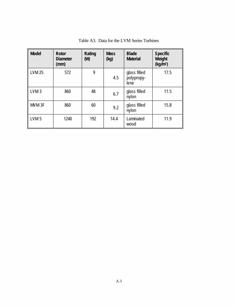
A.3
Table A3. Data for the LVM Series Turbines
Model Rotor Diameter (mm)
Rating (W)
Mass (kg)
Blade Material
Specific Weight (kg/m2)
LVM 25 572 9 4.5
glass filled polypropy-lene
17.5
LVM 3 860 48 6.7 glass filled nylon
11.5
MVM 3F 860 60 9.2 glass filled nylon
15.8
LVM 5 1240 192 14.4 Laminated wood
11.9

APPENDIX B
ELECTRIC POWER GENERATED BY WALKING
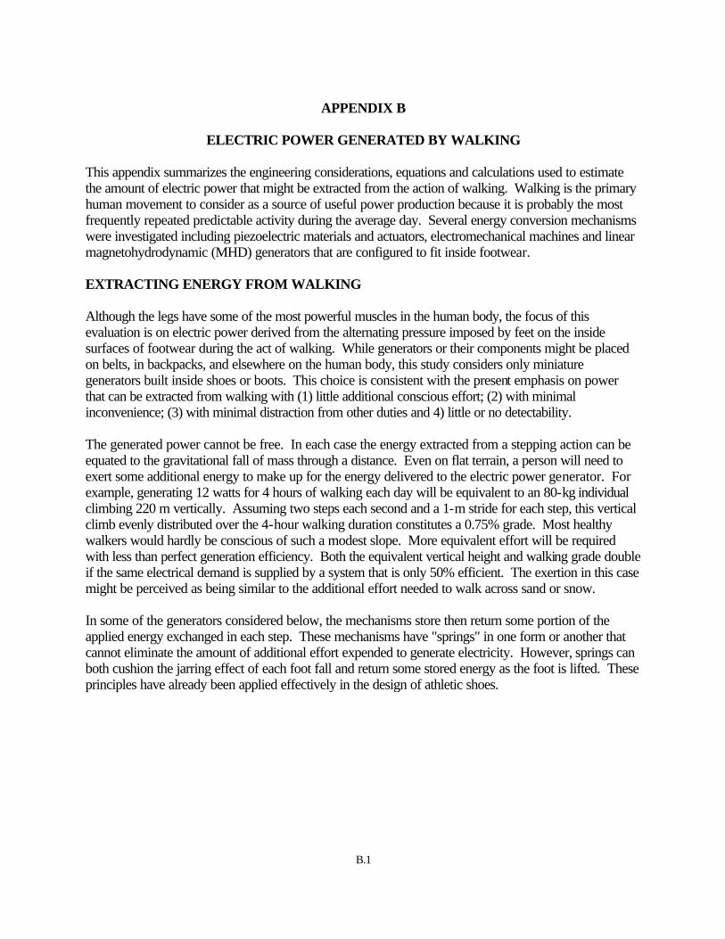
B.1
APPENDIX B
ELECTRIC POWER GENERATED BY WALKING This appendix summarizes the engineering considerations, equations and calculations used to estimate the amount of electric power that might be extracted from the action of walking. Walking is the primary human movement to consider as a source of useful power production because it is probably the most frequently repeated predictable activity during the average day. Several energy conversion mechanisms were investigated including piezoelectric materials and actuators, electromechanical machines and linear magnetohydrodynamic (MHD) generators that are configured to fit inside footwear. EXTRACTING ENERGY FROM WALKING Although the legs have some of the most powerful muscles in the human body, the focus of this evaluation is on electric power derived from the alternating pressure imposed by feet on the inside surfaces of footwear during the act of walking. While generators or their components might be placed on belts, in backpacks, and elsewhere on the human body, this study considers only miniature generators built inside shoes or boots. This choice is consistent with the present emphasis on power that can be extracted from walking with (1) little additional conscious effort; (2) with minimal inconvenience; (3) with minimal distraction from other duties and 4) little or no detectability. The generated power cannot be free. In each case the energy extracted from a stepping action can be equated to the gravitational fall of mass through a distance. Even on flat terrain, a person will need to exert some additional energy to make up for the energy delivered to the electric power generator. For example, generating 12 watts for 4 hours of walking each day will be equivalent to an 80-kg individual climbing 220 m vertically. Assuming two steps each second and a 1-m stride for each step, this vertical climb evenly distributed over the 4-hour walking duration constitutes a 0.75% grade. Most healthy walkers would hardly be conscious of such a modest slope. More equivalent effort will be required with less than perfect generation efficiency. Both the equivalent vertical height and walking grade double if the same electrical demand is supplied by a system that is only 50% efficient. The exertion in this case might be perceived as being similar to the additional effort needed to walk across sand or snow. In some of the generators considered below, the mechanisms store then return some portion of the applied energy exchanged in each step. These mechanisms have "springs" in one form or another that cannot eliminate the amount of additional effort expended to generate electricity. However, springs can both cushion the jarring effect of each foot fall and return some stored energy as the foot is lifted. These principles have already been applied effectively in the design of athletic shoes.

B.2
PIEZOELECTRIC MATERIALS Piezoelectric materials represent one of the most robust solutions to the problem of generating electric power from walking. Very simple generators can be configured with few moving parts. It will be shown that piezoelectric devices allow up to 5 W of electric power to be extracted from walking using innovative means to match mechanical forces and obtain multiple actuations per step. Commercially available piezo actuators convert mechanical energy to electrical energy. The approach taken in this study is to apply commercial piezo actuators in their various present forms and engineer interfaces to match the available actuators with forces generated by walking. Information used in this section includes papers by Giurgiutiu et al. (1994, 1996) on the energy capabilities of available piezo actuators, manufacturers' design handbooks, and a report on the STEPZ generator by White (1972), which has many design principles in common with the piezoelectric "power boot" concept. Theory A force applied to a piezo material will develop an electrical charge across it. A combination of displacement and internal stress will occur in response to this applied force. The piezo film behaves much like an electrical capacitor, so the charge results in a corresponding voltage across the piezo film. If this voltage is relaxed through an external circuit, the internal stresses are also relieved. The voltage goes through zero and is forced negative by the charges that are then created by the release of the external force. Simple Thevenin circuit models of piezoelectrical behavior, while common in piezo material engineering literature, do not fully represent the interplay of the electrical and mechanical energies. A brief mathematical development of that electrical and mechanical interplay is presented below. The instantaneous change of energy can be equated for the mechanical and electrical representations. Given externally applied force Fext, displacement u, voltage V and charge q, the change in energy can be written as
Some mechanical losses occur in the system as unavoidable inefficiencies. Any energies extracted from the piezo system must be represented by comparable hysteresis in the respective force-displacement and voltage-charge state diagrams. An interesting formulation results from using a spring analogy with induced strain displacement uISA (measured without external force) and force per displacement ki (measured without voltage across the device). The induced strain actuation displacement uISA can further be assumed proportional to the device voltage.
dVq.=udF=dE ext

B.3
Several additional substitutions into the energy relationship result in an equation that retains all of the mechanical and electrical character of the piezo material. Electrical power extracted from the system can also be given as a function of voltage. The non-linear result can be simulated by computer to fine tune the system design and better understand this interesting energy exchange. Note that the electrical power P(V,t) leaving the system is itself a simple nonlinear function of the voltage across the device.
Simple Shoe Sole Generator The very simplest configuration of a piezoelectric generator is the application of a single actuator to the sole of a shoe or boot. The report by Giurgiutiu et al. (1996) was used to determine the maximum energies that might be captured by a single actuator being depressed once for each footstep. Using the equation for displacement and force above, the force for maximum energy can be calculated.
And the corresponding energy per footstep can then be found.
Note that this value is twice as large as that used by Giurgiutiu et al. because they assumed that the external force was applied sinusoidally through an external material spring. Their assumption is reasonable where mechanical actuation is being considered; but it is inappropriate here, where the full step force can be applied to the actuator then removed on each step cycle. One of the most energetic actuators is the Polytec PI material P-246.70, which can develop up to 1.3 J per actuation, under ideal conditions. However, assuming the foot pressure generated by an 80-kg person under the force of gravity and the 24% conversion efficiency suggested in the reference, only 94 mJ is produced.
k
F-u=ui
extISA
Vk=u ISAISA
FkF2
-Vk+VFk=t)P(V, exti
extISAextISA &&
uk0.5=F ISAiEmax
uk0.25=E 2ISAimax

B.4
The difference between the ideal and practical energy results from the poor match that is achieved between actuator characteristics and the actuation force. A similar mismatch was found for every available actuator considered in this configuration. As a result, an 80-kg person taking two steps each second can produce somewhat less than 200 mW of electrical power. Methods of Matching Forces While it is possible to improve the force match by a wise choice of actuator, the largest energies will be achieved by first choosing the most energetic or efficient actuators, then using mechanical leverage to match the actuator and applied forces. Several methods for matching the available force and the optimum actuator force were investigated including (1) simple leverage, (2) suspension and tension, and (3) piezo cantilevers and springs. Simple Leverage The torque relationships of a simple lever arm may be used to convert modest forces over several millimeters of displacement to a much larger force over a micrometer displacement. Energy is conserved to give the relation
where the subscript "2" refers to the actuator quantities, and the subscript "1" refers to the lever end, where force is applied. Fluidic conversion of energy is similar enough to this that it should be mentioned. For fluids, the conversion is obtained through differing piston areas. A person's weight might cause a large displacement of a small piston that displaces a large piston that applies much more total force over a shorter stroke. Suspension and Tension Many of the optimum forces for actuating available piezo devices are truly large (e.g., over 22 kN for the Polytec PI material P-246.70). Extreme mechanical advantage must be incorporated to best use these energetic materials. One such concept that obtains great mechanical advantage is the deflection of a suspended mini-cable in tension. A defection of 6.6 mm at the center of a 73-cm chord generates the optimum 22-kN force for two actuators. This chord design is too large to fit in the sole of normal footwear, but if a simple lever or pulley is used to first double the applied force, the chord length drops to 18 cm. This length is compatible with the length of an average size boot. This tension leverage used with the Polytec PI material P-246.70 piezo actuator was estimated to yield 638 mJ per step. This simple scheme could produce in excess of 1.2 W when actuated by an 80-kg person taking two steps per second. Multiple actuations might be possible along the length of the suspended cable. In this configuration, piezoelectric generation from continuous walking could approach the 5-W level.
,uMg=uF 122

B.5
Piezo Cantilevers and Springs Actuation of piezo bimorph cantilevers might be used to transform moderate forces along the cantilever into much higher actuation forces. Small bending motions result in large opposing displacements on the top and bottom of the cantilever. A complete analysis of this concept was not performed, but it is anticipated that a piezo bimorph in either cantilever or spring configuration could achieve some of the mechanical advantage demonstrated by the suspended mini-cable discussed above. Methods of Obtaining Multiple Actuations Conversion of the energy available in each step can be limited by the properties of available actuators. In many instances, however, it may be possible to repeat the piezo energy extraction multiple times during each step. Providing that the displacement of one actuator does not limit that of neighboring elements, the energy generated per step can increase linearly with the number of actuations per step. Two methods were considered for obtaining multiple actuations from each step--(1) multiple displacements along a rounded sole and (2) ratchet-type displacement. Multiple Displacements Along a Rounded Sole Each of the above listed piezo actuations might be repeated several times along a rounded shoe or boot bottom. For example, using the tension cord displacement method described earlier, the same chord might be depressed several times during a single step. The electronic power conversion must be designed to make good use of these multiple actuations, i.e., the circuit time constant must be short enough to use the full stroke of the actuator. Ratchet Displacements Another strategy to obtain multiple actuations in a single step is to design a ratchet-like structure that is squeezed between the piezo actuator and a firm wall. The varying thickness of the ratchet permits the actuator to change between its zero force and optimum force displacements. The following energy balance relates the applied and actuator energies during changes in ratchet thickness.
This actuation principle, unlike the others discussed before, provides the option of applying an optimized piezo actuation multiple times in series for the same displacement stroke. More than two or three interactions in the same stroke might cause the overall actuation stroke to become excessive. A total stroke of about 3 cm is probably all that a person would tolerate on a shoe sole before the device feels too mushy for comfort. The ratchet-powered multiple actuation principle is viable in other piezo generator applications.
uF=Mgu EE1 maxmax

B.6
MINIATURE ELECTROMAGNETIC MACHINES The use of miniature rotating electromagnetic machines for mechanical to electrical conversion offers a way to capture the greatest amount of energy from walking-generated pressure. The extractable energy is limited by human fatigue rather than material considerations. Therefore, the production of about 20 W continuously may be a reasonable design goal for this concept. Miniature mechanisms can be designed that permit nearly unlimited actuation stroke, and the resulting electrical energy is likely in a voltage and current range amenable to conventional electrical power conditioning. In this category, the concept considered is a miniature rotating machine (a small, axial flux generator) driven by a kinetic electromechanical conversion strategy, named appropriately "button and string actuation." Miniature Rotating Machine Design The variety of possible rotating machines to consider for this application is quite great. An axial flux, permanent magnet design is taken as a representative example because (1) the axial flux configuration permits compact, powerful generation as a result of continuing improvements in permanent magnet strengths; (2) the axial geometry is conducive to compact, multiple pole generation; and (3) permanent magnet fields without electrical field excitation improve efficiency for low power applications. In this machine, multiple disk-shaped permanent magnets lie flat on a rotor disk. As the rotor disk rotates, the magnets pass over coils on a second flat stator disk. These coils might be conveniently fabricated as printed circuits in this scale. The change in flux in the coils as the permanent magnets pass over each coil produces a voltage, which might be captured to charge a battery or capacitor. Generated voltage and power output of this machine increase with rotational frequency, number of magnet pole pairs, peak magnetic flux, and number of coil windings. Many means of coupling the kinetic motion of a person's step to rotation of the machine rotor appear possible. One innovative configuration is to use the stepping force to alternately wind and unwind multiple wires that go through multiple holes in the machine rotor. The concept reflects a child's game in which a button is rotated at high speed by applying periodic tension to two strings strung through the button holes and drawn tight between fingers on two hands. In the micro-machine, the stepping force acting against the fully wound rotor accelerates the rotor until the wires are completely unwound. The momentum at this point rewinds the wires in the opposite direction as the stepping force is removed, and the rotor becomes fully wound once again just as the stepping force is reapplied.

B.7
Theory The following equations establish the output potential of the concept. First, the equivalent RMS voltage VRMS obtained from the rotational system depends upon the number of windings N on each coil and the rate of change of magnetic flux B that links each coil of surface area S and diameter D. If the coils are series connected, the voltage is also proportional to the even number of magnetic pole faces p. VRMS is given by
Note that while strong (perhaps rare earth) magnets can be made in nearly any shape or size, the industry has a demonstrated capability to manufacture 1.25-cm diameter disks that weigh about 1.5 grams and have nearly 0.2-Tesla induction (B0). The magnetic flux in each coil varies sinusoidally with the rate at which the pole faces pass a coil. If fm is the mechanical rotation rate of the rotor and Bo is the induction of a single magnet,
The given assumptions about magnet size and induction can be used to give a simple relation for achievable voltage from this rotating machine set. In this relation, fm is the mechanical rotation frequency.
Electrical Power Extraction The number of poles will be limited by the need to fit a number of magnets on a rotor inside the boot's sole. The number of coils will also be constrained somewhat by available space, and the rotational frequency may be limited by the practicality of achieving and controlling some rotational speed. A trade-off will also exist between voltage and N because low voltages necessitate high current and therefore necessitate larger conductors that further limit the number of coils that can be accommodated. It appears, however, that useful parametric solutions exist near N = 10, p = 8, fm = 200 Hz and VRMS = 2 volts. This voltage level is readily converted and stored by conventional diode rectifiers, battery cells and associated electronics.
∫
2D
=dS2
π
dSBdtd
2Np
-=V RMS •∫
The surface area may be approximated by the pole face area of the permanent magnets of diameter D.
.eB=B(t) ptfjo
mπ
Npf)5-(5.8EV2
mRMS ≅

B.8
Rotational Dynamics The rotational dynamics of such a system can be described by a second order rotational system driven by torques resulting from stepping force and electrical extraction.
Note that the torque caused by stepping is itself approximated by a step function. The electrical torque might be represented from power extraction in a diode bridge.
LINEAR MAGNETOHYDRODYNAMIC GENERATION The Lorentz force can be used to convert the kinetic energy of flowing liquid metal into electrical energy within a small liquid metal MHD generator. An electrical field is induced in a liquid metal passing through a strong magnetic field. The electric field can be combined with a carefully designed external load circuit to capture electrical energy. PNNL has researched liquid metal actuator, pump and generator systems since 1993. Design equations and graphs have been collected to design both pumps and generators with liquid metal channels in the sub-millimeter range. From this experience, it appears that a liquid metal piston or collapsible reservoir can be designed to feed a liquid metal generator sized to fit into the sole of a boot. Design Concept In this design, the piston or reservoir can be nearly the area of a boot heel (50 cm2 is assumed). The cross section area of the liquid metal generator itself is in the millimeter range. The liquid metal is expelled into an unpressurized container with no gravitational head by the force of stepping. As the foot is lifted, the liquid metal spills back into the initial reservoir through a return flap. As an alternative, the liquid metal can be forced from the heel region toward the foot by the rocking motion of the foot as the step action advances. The liquid metal that flows through the generator immediately back fills behind the depression caused by the rocking motion of the foot. In both of the suggested methods for converting the gravitational force of the foot into liquid metal motion, the generation is active during only the time that the foot is pressing down with gravitational force. An evaluation was performed to determine whether return springs or gravitational forces can be utilized to design a system that has continuous liquid metal flow through the generator and, therefore, continuous rather than pulsed generation at stepping frequency. The energy produced by the generator is proportional to the square of the liquid metal velocity. Without working against a gravity head or return spring, the generator fluid velocity is a constant. The fluid velocity in a system with either gravity or
θθθττ K+D+J=- electstep&&&
R
V-V|V|=P=charge
2BATTBATTRMSelec
elecωω
τ
if VRMS ≥ VBATT and 0 otherwise.

B.9
spring return mechanism approaches the extremes exponentially and asymptotically. The majority of the system's response time (spring throw) must be used to assure that a fluid equilibrium is reached (i.e., the same fluid must pass through the generator in both forward and return generator modes). Operating at or above the time constant of the system guarantees that less than half the energy of the constant velocity device is produced. Therefore, it is of no value to use return springs or pressure heads in this device to produce power continuously. Design Parameters A table was prepared to demonstrate the trade-offs that must be made in the design of a small liquid metal generator. The parameters in Table B1 are: 1) generator efficiency (η); 2) cross section area of the liquid metal generator channel (Agen); 3) total input power needed to generate 10 W (Pin); 4) magnetic induction in Tesla (B); 5) assumed heel area (Aheel) that can be used to compress the liquid metal fluid under the gravitational force of an 80-kg person; 6) the assumed active generator length; 7) the average liquid metal velocity through the generator channel (u); 8) the total mass of liquid metal that passes through the generator during one step cycle (assuming two steps per second); and 9) the effective climbing rate (in cm per step) that a person would experience for the generator with the given efficiency. A critical trade-off is illustrated in this table. Very small amounts of power are obtained from small quantities of liquid metal at low efficiency. The poor efficiency means that considerable effort and exertion will be apparent. Because of these shortcomings, the electric power generation potential of an MHD device in this configuration is probably limited to less than 5 W. To obtain this power at high efficiency requires an unacceptably large volume of liquid metal.
Table B1. Trade-Offs in the Design of Miniature Liquid Metal Generator
η (%) Agen (m2) Pin (W) B (T) Aheel (sq.cm)
Length (m)
u (m/s) Mass (g)
Climb (cm/s)
5 4E-7 200 0.2 50 0.1 7 20 25
10 1E-6 100 0.2 50 0.1 16 110 13
20 2.6E-6 50 0.2 50 0.1 32 570 6
40 1E-5 25 0.2 50 0.1 56 3900 3

B.10
REFERENCES Giurgiutiu, V., C. A. Rogers and Z. Chaudhry. 1996. "Energy-Based Comparison of Solid-State Induced-Strain Actuators." Journal of Intelligent Material Systems and Structures, Vol. 7, No. 1, pp. 4-14. Giurgiutiu, V., Z. Chaudhry and C. A. Rogers. 1994. "The Analysis of Power Delivery Capability of Induced Strain Actuators for Dynamic Applications." Proceedings of the Second International Conference on Intelligent Materials: ICIM '94, pp. 565-576. White, M.A.. 1972. "Proof-of-Principle Investigation of 300 W(e) Stirling Engine Piezoelectric (STEPZ) Generator." McDonnell Douglas Astronautics Company Interim Report MDC G3133, Huntington Beach, California.

PNNL-13336
Distr-1
Distribution
No. of Copies OFFSITE
CDR, USAIC ATTN: ATZB-TS Fort Benning, GA 31905 Attn: Ken Sutton CWT Technologies Suite 108 350 Hills Street Richland, WA 99352 Attn: L.A. Schienbein Dismounted Battlespace Battle Lab Bldg 4, Room 347 Fort Benning, GA 31905 Attn: Chris Kearns Hammerstrom Energy Applications and Technologies 2000 Longston Blvd. Richland, WA 99352 Attn: D. J. Hammerstrom HQ, US Army Material Command ATTN: AMCRDA-STE 5001 Eisenhower Ave Alexandria, VA 22333-0001 Attn: Renata Price Institute for Defense Analyses 1801 N. Beauregard St. Alexandria, VA 22311-1772 Attn: Robert Zirkle Marine Corps Warfighting Lab 3255 Meyers Ave Quantico, VA 22134-5051 Attn: Joseph M. Thompson
No. of Copies ODUSD (S&T) 1777 N. Kent Street, Suite 9030 Rosslyn, VA 22209 Attn: Tim Steele Office of Naval Research 800 North Quincy Street Suite 804/ONR 353 Arlington, VA 22217-5660 Attn: Gerald Nalepa Project Manager Soldier 10401 Totten Road, Ste 121 Fort Belvoir, VA 22060-5852 Attn: William K. Brower SAAL-TT Suite 9000 2511 Jefferson Dave Highway Arlington, VA 22202 Attn: Larry Stotts TRADOC System Manager – Soldier ATTN: ATZB-TS, Bldg 4 Rm 632 Fort Benning, GA 31905 Attn: Walt Holton US Army CECOM AMSEL-RD-C2-AP Fort Monmouth, NJ 07703-5201 Attn: Robert P. Hamlen U.S. Army CECOM AMSEL-RD-ST-WL-AW Fort Monmouth, NJ 07703-5203 Attn: Perry Hugo

PNNL-13336
Distr-2
No. of Copies U.S. Army Research Laboratory Director ATTN: AMSRL-HR (Dr. Robin L. Keese) APG, MD 21005-5425 US Army Research Laboratory ATTN: AMSRL-HR-SB (L. Fatkin) Bldg 459 Aberdeen Proving Ground, MD 21005-5425 US Army Research Laboratory Sensors & Electronic Devices Dir (SEDD) 2800 Powder Mill Rd Adelphia, MD 20783-11197 Attn: John Pellegrino US Army Soldier Biological & Chemical Command (SBCCOM) Natick Soldier Center (AMSSB-RSC-D) Natick, MA 01760-5056 Attn: Philip Brandler US Army Soldier Biological & Chemical Command (SBCCOM) Natick Soldier Center Natick, MA 01760 Attn: Edward Hirsch US Army Soldier Biological & Chemical Command (SBCCOM) Natick Soldier Center (AMSSB-RIP N) Natick, MA 01760 Attn: Robert Kinney
No. of Copies US Army Soldier Biological & Chemical Command (SBCCOM) Natick Soldier Center (AMSSB-RSC-D) Natick, MA 01760-5056 Attn: Theodore T. Mattus, Jr. US Army Soldier Biological & Chemical Command (SBCCOM) Natick Soldier Center (AMSSB-RIP-B N) Natick, MA 01760 Attn: Janet E. Ward USSOCOM/SOAL-T 7701 Tampa Point Blvd MacDill AFB, FL 33621-5323 Attn: Steve Comer ONSITE C.T. Chase, BWO R.G. Clemmer, K6-48 20 J. Desteese, K5-20
T.E. Divine, K6-48 10 T.J. Doherty, K8-21 10 T.A. Lewallen, K9-55
M.P. Morgan, K5-20 M.H. Ralston, K6-48 R.E. Rhoads, K5-22 P. Sliva, K8-58 H.A. Undem, K6-48
7 Information Release K1-06