Elastic-Plastic Failure Analysis of Pressure Burst Tests ...
14
WAPD-T-3123 Elastic-Plastic Failure Analysis of Pressure Burst Tests of Thin Toroidal Shells D. P. Jones J. E. Holliday L. D. Larson DE-AC11 -93PN38195 NOTICE Thk nport war proprod a0 an .cownt of work rp0n.or.d by tho Unltod Stator Govornmont N.ith.r M UnM Stator, nor tho Unltod Statoa Dopartmat of Energy, nor any of W r mployeer, nor any of th.k W8ctor0, ~lbconiractorr, or thdr omployno, maker any warr.nty, oxprou or implkd, or -mu any logal lkbllfty or roopondblllty for th. accuracy, complotonou or uwhtlnou of any Infomution, mpparatuo, product or procou dldoood, or roprooonto th.1 itr uoe would not Infrlnge privatoly ownod righto. WEST MIFFLIN, PENNSYLVANIA 15122-0079 Operated for the U.S. Department of Energy by WESTINGHOUSE ELECTRIC CORPORATION a Division of CBS 19980529 029
Transcript of Elastic-Plastic Failure Analysis of Pressure Burst Tests ...
WAPD-T-3123
Elastic-Plastic Failure Analysis of Pressure Burst Tests of Thin Toroidal Shells
D. P. Jones J. E. Holliday L. D. Larson
DE-AC1 1 -93PN38195
NOTICE Thk nport war proprod a0 an .cownt of work rp0n.or.d by tho Unltod Stator Govornmont N.ith.r M U n M Stator, nor tho Unltod Statoa Dopartmat of Energy, nor any of W r mployeer, nor any of th.k W8ctor0, ~lbconiractorr, or thdr omployno, maker any warr.nty, oxprou or implkd, or -mu any logal lkbllfty or roopondblllty for th. accuracy, complotonou or uwhtlnou of any Infomution, mpparatuo, product or procou dldoood, or roprooonto th.1 itr uoe would not Infrlnge privatoly ownod righto.
WEST MIFFLIN, PENNSYLVANIA 15122-0079
Operated for the U.S. Department of Energy by WESTINGHOUSE ELECTRIC CORPORATION
a Division of CBS
19980529 029

WAPD-T-3123 (Paper) Page 2
(This Page Intentionally Blank)

DISCLAIMER
This report was prepared as an account of work sponsored by an agency of the United States Government. Neither the United States Government nor any agency thereof, nor any of their employees, makes any warranty, express or implied, or assumes any legal liability or mponsibility for the accuracy, completeness, or use- fulness of any information, apparatus, product, or process disclosed, or represents that its use would not infringe privately owned rights. Reference herein to any spe- cific commercial product, proms, or service by trade name, trademark, manufac- turer, or otherwise does not necessarily constitute or imply its endorsement, m m - mcndktion, or favoring by the United States Government or any agency thereof. The views and opinions of authors expressed herein do not necessarily state or reflect those of the United States Government or any agency thereof.

WAPD-T-3 123 Page 1
Elastic-Plastic Failure Analysis of Pressure Burst Tests of Thin Toroidal Shells
D. P. Jones
J. E. Holliday
L. D. Larson
Westinghouse Electric Company A Division of CBS
West Mifflin, PA 15122-0079
ABSTRACT
This paper provides a comparison between test and analysis results for bursting of thin toroidal shells. Testing was done by pressurizing two toroidal shells until failure by bursting. An analytical criterion for bursting is developed based on good agreement between structural instability predicted by large strain-large displacement elastic-plastic finite element analysis and observed burst pressure obtained from test. The failures were characterized by loss of local stability of the membrane section of the shells consistent with the predictions from the finite element analysis. Good agreement between measured and predicted burst pressure suggests that incipient structural instability as calculated by an elastic-plastic finite element analysis is a reasonable way to calculate the bursting pressure of thin membrane structures.
1 .O Introduction
The ability of large strain-large displacement elastic plastic finite element analysis [LS-LD-EP- FEA] to predict the burst pressure of thin toroidal membranes is demonstrated by comparing analysis results to test data. Testing was performed
on two thin toroidal shells made from Alloy 600 material and welded into a high pressure test fixture. The test specimens were hydrostatically pressurized to bursting at room temperature. Test data accumulated during the test consisted of pressure versus torus cross section diametral dilation, burst pressure, identification of failure location and identification of failure mode by fracture surface.
LS-LD-EP-FEA were performed using stress- strain curves representative of the actual materials tested. Analytical failure is defined as the point for which an incremental increase in applied pressure results in a very large (or indeterminate) increase in the torus diameter of the shell. This pressure is called the incipient failure pressure and for these tests, it was 5 % larger than the actual burst pressures. The LS-LD-EP-FEA based limiting location is in the membrane section on the inner diameter side of the torus and coincides with the location observed in the tests.
The good agreement between test and analysis in terms of burst pressure, pressure-displacement behavior and failure location demonstrates the ability of LS-LD-EP-FEA to predict the failure of

W APD-T-3 123 Page 2
.
thin membrane structures without having to resort to artificial limits such as one-half the elastic slope method advocated by the ASME Boiler and Pressure Vessel Code, (1995).
2.0 Testing
A detailed summary of the test phase of this investigation is discussed below. Testing was done by Pressure Services Industries, Inc. for the Westinghouse Bettis Atomic Power Laboratory.
a. Test Fixtures
The test specimens are installed into the test fixture as shown in Figure 1.
b. Specimen Geometry
The specimens tested in this investigation consisted of two thin toroidal shells. The geometry associated with the test specimens is shown in Figure 2. The specimens consist of an inner and an outer half. Each half is welded into a test fixture and the two halves are welded together at the top. The as welded test assembly does not receive a post weld heat treatment or stress relief.
c. Test Instrumentation
Strain gage and displacement measurements were made at various stages of the test right up to failure. Unfortunately, the strain gage data was internally inconsistent and not usable for purposes of qualifying analytical results.
The instrumentation of interest in this particular investigation are the dial gages shown in Figure 1 which measure the radial displacement of the inner and outer membrane portions of the test specimen. The dial gages were calibrated to be accurate to within 0.001 inch (0.0254 mm) and the strain gages to within idin.
d. Test Procedure
Burst testing of the toroidal shell was performed by hydrostatically pressurizing the shell in the Figure 2 test assembly from 0 psi to burst at room temperature. Displacement dial gage readings were taken at 500 psi (3.45N/mm2) increments from 0 to 12,000 psi (82.7N/mm2). Dial gages were removed at 12,000 psi (82.7 N/mm2)in the interest of safety. For pressures above 12,000 psi (82.7 N/mm2), the test pressure was slowly increased until failure by bursting occurred. The failure pressure and location of failure were recorded.
e. Test Results
The test results of interest are:
Failure pressure: Test specimen 1 - 14,350 psi (98.9 N/mm2) Test specimen 2 - 14,400 psi (99.3 N/mm2) Failure location is in the membrane potion of the shell and is located on the inner diameter side of the specimen. The failure location is identified as location A in Figures 1 and 2. The fracture surface, shown in Figure 3, indi- cates that failure was by ductile rupture.
Pressure-displacement curves from the dial gage readings are presented with the analysis results.
3. Analysis
Details associated with the analytical portion of this study are discussed below.
a. Assumpions
The following assumptions were made in the analysis.
(1) Assumption
The elastic-plastic analysis of the test specimen is conducted assuming an isotropic hardening material law.

WAPD-T-3 123 Page 3
Justification
Since the specimens were tested by application of monotonically increasing pressure to failure, there is no reversal of load thus eliminating cyclic hardening concerns. Kinematic or mixed hardening effects are thus limited to very local unloading regions and considered second order for these tests.
12) Assumption
The residual stress state in the test specimen is not considered in this analysis.
Justification
The residual stress state in the specimen is not considered since residual stress has little effect on ductile rupture and burst at the ultimate state of the material. The reason for this is that loading ductile materials to very large strains will convert residual strains in the specimen to mechanical stresses. At failure in regions of high ductile strain, only the mechanical stresses due to applied loads remain just prior to failure. However, residual stresses will affect distortions. This is born out by the fact that good agreement was found between computed and burst pressure but there could be considerable error in the computed distortion of the shell.
/3) Assumption
The LS-LD-EP-FEA is carried out until the numerical solution becomes unstable, e.g. when a converged solution for an additional increment of load is numerically difficult to obtain. At this point, the slope of the load-displacement curve for the shell becomes vanishingly small. The total pressure that causes this condition is the incipient failure pressure.
Justification
Failure in the test occurs when the shell bursts. Instead of trying to predict local ductile rupture or
tearing from the FEA results, it is proposed here that a useful definition of failure is the pressure for which the structure approaches dimensional instability, i.e. unbounded displacement for a small increment in pressure. This condition is symptomatic of an ill-conditioned boundary value problem caused by the combined changes in geometry and material stiffness leading to a physical instability. This is often preceded by numerical convergence problems. The numerical convergence problem is indicative of impending structural collapse and is characterized by the slope of the load-displacement plot approaching zero. A horizontal load-displacement plot means that the displacement grows unbounded with a small increase in load. The hypothesis of this paper is that the pressure just preceding this numerical instability can be correlated to actual structural collapse and/or material failure by local thinning (or necking down) leading to ductile rupture.
b. Finite Element Model
The geometry analyzed is shown schematically in Figure 1. The as welded geometry is shown in Figure 2.
The finite element model used to conduct the LS- LD-EP-FEA of the test specimens is a two- dimensional (2-D) axisymetric model and is shown in Figure 4. The finite element model consists of:
41,541 Nodes
13,482 Eight node reduced integration quadri- lateral elements (CAX8R)
c. Material Properties
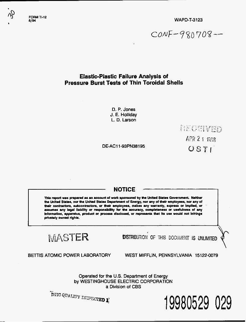
The material properties used in the LS-LD-EP- FEA of the test specimens are shown in Figure 5.
d. Boundary Conditions
Boundary conditions applied to the FE model are

*
shown in Figure 4. The boundary of the fixture is assumed to be fixed against all motion. There was no motion of these surfaces observed during the test.
e. Computer Prosrams
The LS-LD-EP-FEA was conducted using ABAQUS (1994) The FE model shown in Figure 3 was devel- oped using PATRAN (1990).
4. Results
Salient results and comparison to appropriate test data is summarized below:
a. Burst Pressure
The analysis predicts failure at a pressure of 15,043 psi (104 N/mm2) compared to 14,350 (98.9 N/mm2) and 14,400 psi (99.3 N/mm2). The computed value is less than 5% larger than the lowest measured burst pressure.
b. Failure Location and Failure Mode
The specimens failed in the membrane portion of the shell on the inner diameter side of the test specimen as shown schematically in Figures 1 and 2. The fracture surfaces, shown if Figure 3, are consistent with a ductile rupture failure mode.
The analysis predicts failure at the location of maximum average equivalent plastic strain (PEEQ) at the state of incipient failure. A contour plot of this result superposed on an exaggerated displacement plot at failure is shown in Figure 6. From Figure 6 the failure location is observed to occur in the membrane portion of the inner diameter surface of the shell (location A). This location coincides with average through-section PEEQ levels of 21 .O% suggesting this is the likely region of ductile rupture.
c. Load-Displacement Response
W APD-T-3 123 Page 4
A comparison of test based and analytically predicted pressure-displacement response of the test specimens is shown in Figure 7. The slope of the pressure-displacement curve from the LS-LD- EP-FEA is approaching zero at 15,043 psi (104 N/ mm2) which is within 5% of the observed test burst pressure. Significant error is observed in the distortion of the torus for a given pressure. This error is attributed to the residual stress state.
5. Discussion of Results
Based on a comparison of test data and analysis results the following observations are made:
e
e
e
Predicted incipient failure pressure is within 5% of measured burst pressures. This suggests that structural instability as calculated by near zero load-displacement slope from LS-LD- EP-FEA can be used to predict bursting of thin toroidal shells. The predicted failure location, based on the maximum average PEEQ across the thickness of the test specimen agrees with the observed failure location in the test specimen. The analytically based load-displacement response of the test specimen under predicts the measured load-displacement response. Neglecting residual stresses in the computa- tions resulted in good agreement for burst pressure, but poor agreement for displace- ment.
6. Conclusions
The good agreement between calculated and observed burst pressures suggests the following conclusions:
The calculation of incipient structural instabil- ity does not require detailed treatment of the welding residual stress state or consideration of local weld geometry since neither of these were included in the LS-LD-EP-FEA used here. The good agreement between predicted and

WAPD-T-3 123 Page 5
actual burst pressures suggests that the incipi- ent failure pressure as defined by approaching a zero slope of a calculated load-displacement curve is a practical and reasonable way of esti- mating burst pressure of thin members.
7. Acknowledgment
The work was performed under a U.S. Department of Energy contract with the Bettis Atomic Power Laboratory, a unit of the Westinghouse Electric Corporation. The experimental portion of this study was designed and followed by Mr. Michael Connelly of the Bettis Atomic Power Laboratory. Actual testing was conducted under a subcontract at Professional Services Industries, Inc.
8. References
The American Society of Mechanical Engineers Boiler and Pressure Vessel Code, New York, NY, 1995 Edition
ABAQUS - Hibbitt, Karlson and Sorenson, Inc. - Version 5.4, 1994.
PATRAN - PDA Engineering - Release 2.5 - October 1990.

WAPD-T-3 123 Page 6
Figure 1. THIN TOROIDAL SHELL BURST TEST SCHEMATIC AND INSTRUMENTATION DIAGRAM
Figure 2. THIN TOROIDAL SHELL BURST TEST - AS WELDED GEOMETRY

WWD-T-3 I23 Page 7
I
. . . . . . . I .
Figure 3. THB TOROLDAL SHELL BURST TEST - IDEhTTDFXCATION OF BURST SITE Ah;D FRACTURE SURFACE
F /
x 5 3 \ /
FrXtr/ \”I,.:/
x
- . -
- Figure 4. TflIh’TORUIDAL SHELL BURSTTEST ANALYSIS - F3NTE
ELEMENT MODEL AN3 BOUKDARY C0h;DITIUNS
WAPD-"-3123 I
:m
Page 8 ALLOY SO0 AND ALLOY 600 WELD METAL ELASTlC PROPERTiES AND TRUE STRESS-TRUE STFNN C E V 3 CZE3 iS 3 i E ANALYES OFTSETSIR 13R3II)ALSREE
Figure 5. THIK TOROIDAL, SHELL BURST TEST AKALYSIS - MATERIAL PROPERTIES
Figure 6. THIN TOROIDAL SHELL BURST TEST AKALYSIS - EQUIVALEhT PLASTIC STRAIN AT POINT OF INCIPEIXT hV-UYTICALLY PREDICTED FAILURE

m
A P P L * I E D
T P h R ' E '
s o s : "
;: E
P s S 1 )
0
WAPD-T-3 123 Page 9
TOROIDAL SHELL DIAMETRAL DILATION VS APPLIED PRESSURE TESTDATA VS TEST ANALYSIS
0 Om 0.1 TOROIDAL SHELL DIAMETRALDILATION (IN)
+3OdOckT&D& - 7 odock TwtData
+ 11 odockTutData - ELASTIC-PLASTIC ANALYSIS
0.15
Figure 7. THIN TOROIDAL SHELL ANALYSIS - PRESSURE VERSUS DIAMETRAL, DILATION

WAPD-T-3123 Page 10
(This Page Intentionally Blank)
M98004956 I llllllll Ill lllll1111111111 lllIl1111111111111111111 I111
Publ. Date (1 1) 149809-
uc Category (19) Sponsor Code (1 8)
DOE