Calculation of the Hoop Burst Speed for Rotating Discs · 5590.2 ≅1.10 (7) The two preceding...
14
Calculation of the Hoop Burst Speed for Rotating Discs In high speed turbomachinery, the discs which support the blades are highly loaded structural members. The kinetic energy in discs is considerable and whilst designed to avoid burst failure, if this occurs the surrounding structure is often not strong enough to contain the disc fragments, e.g,: http://www.telegraph.co.uk/news/2016/10/30/american-airlines-plane-engine-flung-debris-in-rare-risky-failur/ The primary loading faced by a turbomachinery disc is that induced by rotation. This includes centrifugal self-loading and a radial load at the periphery due to the centrifugal loading of the attached blades and such loading induces stresses in the disc that are proportional to the square of the angular velocity . Although, the detailed design of a disc might include consideration of a range of potential failure mechanisms like, for example, low cycle fatigue induced by thermal and mechanical cycling, the basic disc shape is governed by the basic strength requirement to resist circumferential or hoop burst. Whilst hoop burst of a rotating disc is a phenomenon involving material plasticity and large displacements and strains, a rather simple approach, based on a linear-elastic analysis of an axisymmetric model of the disc, has been shown to provide sufficiently accurate predictions of the burst speed for the purposes of initial design. The method is attributed to Robinson, [1], and is discussed on p50 of Chianese Stefano’s 2011 Master’s thesis, [2]. Hoop burst involves the circumferential or hoop stress which varies over the generator plane of the disc. Robinson’s method requires the area weighted average hoop stress to be calculated for a given angular velocity . The angular velocity to cause the disc to burst is given in terms of the ultimate tensile strength, , of the material. Figure 1: Generator planes for the axisymmetric finite element analysis of two rotating discs The Challenge The reader is asked to use his/her finite element system to determine the angular velocity to cause the two discs of Figure 1 to burst based on a UTS of 1000MPa. For this study, no radial loads due to blades are considered. For the parallel sided disc the theoretical solution based on the Lamé equations can be used for software verification – see for example reference [3]. The second, tapered, disc has no theoretical solution and solution verification will need to be used to ensure that the mean hoop stress calculated by the axisymmetric finite element model has converged sufficiently. Raison d’être for the Challenge A great virtue of finite element (FE) analysis is that once software and solution verification have been carefully undertaken then the engineer may freely use a finite element model to explore in more detail the mechanics of a design and therefore put under scrutiny the design rules adopted for his/her component of interest. This challenge puts the empirical design rule of Robinson for the prediction of burst in rotating discs under such scrutiny. The process uncovers some interesting facts about the finite element where the average hoop stress is given by and A is the area of the disc generator plane. Parallel Tapered Axis of Rotation Inner radius = 0 Outer radius = 0.1m Inner thickness = 0.03m Outer thickness = 0.03m and 0.015m =210GPa =0.29 =1000MPa =7800kg/m 3
Transcript of Calculation of the Hoop Burst Speed for Rotating Discs · 5590.2 ≅1.10 (7) The two preceding...

Calculation of the Hoop Burst Speed for Rotating Discs
In high speed turbomachinery, the discs which support the blades are highly loaded structural members. The kinetic
energy in discs is considerable and whilst designed to avoid burst failure, if this occurs the surrounding structure is often
not strong enough to contain the disc fragments, e.g,:
http://www.telegraph.co.uk/news/2016/10/30/american-airlines-plane-engine-flung-debris-in-rare-risky-failur/
The primary loading faced by a turbomachinery disc is that induced by rotation. This includes centrifugal self-loading and a
radial load at the periphery due to the centrifugal loading of the attached blades and such loading induces stresses in the
disc that are proportional to the square of the angular velocity �. Although, the detailed design of a disc might include
consideration of a range of potential failure mechanisms like, for example, low cycle fatigue induced by thermal and
mechanical cycling, the basic disc shape is governed by the basic strength requirement to resist circumferential or hoop
burst. Whilst hoop burst of a rotating disc is a phenomenon involving material plasticity and large displacements and
strains, a rather simple approach, based on a linear-elastic analysis of an axisymmetric model of the disc, has been shown
to provide sufficiently accurate predictions of the burst speed for the purposes of initial design. The method is attributed
to Robinson, [1], and is discussed on p50 of Chianese Stefano’s 2011 Master’s thesis, [2].
Hoop burst involves the circumferential or hoop stress �� which varies over the generator plane of the disc. Robinson’s
method requires the area weighted average hoop stress ��� to be calculated for a given angular velocity �. The angular
velocity to cause the disc to burst is given in terms of the ultimate tensile strength, ����, of the material.
Figure 1: Generator planes for the axisymmetric finite element analysis of two rotating discs
The Challenge
The reader is asked to use his/her finite element system to determine the angular velocity to cause the two discs of Figure
1 to burst based on a UTS of 1000MPa. For this study, no radial loads due to blades are considered. For the parallel sided
disc the theoretical solution based on the Lamé equations can be used for software verification – see for example
reference [3]. The second, tapered, disc has no theoretical solution and solution verification will need to be used to ensure
that the mean hoop stress calculated by the axisymmetric finite element model has converged sufficiently.
Raison d’être for the Challenge
A great virtue of finite element (FE) analysis is that once software and solution verification have
been carefully undertaken then the engineer may freely use a finite element model to explore in
more detail the mechanics of a design and therefore put under scrutiny the design rules adopted for
his/her component of interest.
This challenge puts the empirical design rule of Robinson for the prediction of burst in rotating discs
under such scrutiny. The process uncovers some interesting facts about the finite element
�� ��� ���� where the
average hoop stress is given
by ��� �������� and A is the
area of the disc generator
plane.
Pa
rall
el
Ta
pe
red
Axis of Rotation
Inner radius = 0
Outer radius = 0.1m
Inner thickness = 0.03m
Outer thickness = 0.03m and 0.015m
�=210GPa
�=0.29
����=1000MPa
�=7800kg/m3
modelling of such components and also brings into sharp focus the inadequacy of the empirical
design rule which is still used to this day!
The Robinson approach relies on an empirical correlation between the average hoop stress at burst
and the ultimate tensile strength of the material. A rational basis for this can be developed by
considering the theoretical solutions for a rotating disc with parallel sides.
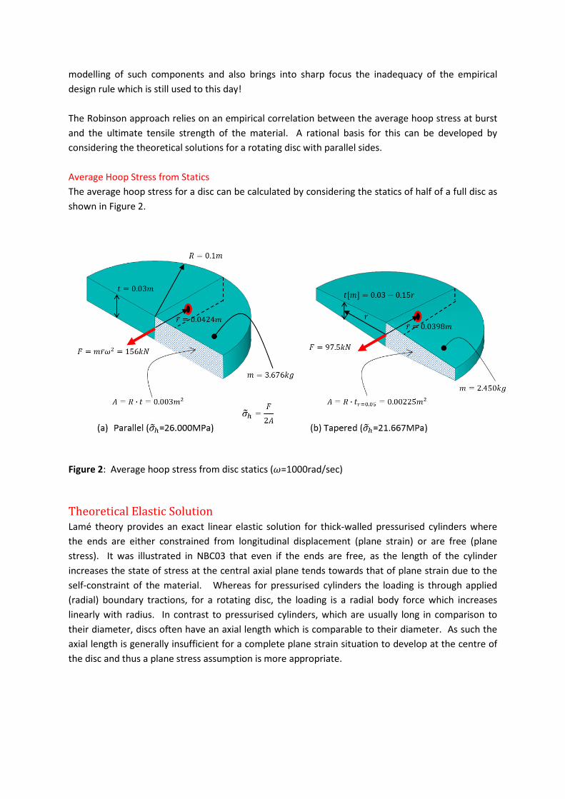
Average Hoop Stress from Statics
The average hoop stress for a disc can be calculated by considering the statics of half of a full disc as
shown in Figure 2.
Figure 2: Average hoop stress from disc statics (�=1000rad/sec)
Theoretical Elastic Solution
Lamé theory provides an exact linear elastic solution for thick-walled pressurised cylinders where
the ends are either constrained from longitudinal displacement (plane strain) or are free (plane
stress). It was illustrated in NBC03 that even if the ends are free, as the length of the cylinder
increases the state of stress at the central axial plane tends towards that of plane strain due to the
self-constraint of the material. Whereas for pressurised cylinders the loading is through applied
(radial) boundary tractions, for a rotating disc, the loading is a radial body force which increases
linearly with radius. In contrast to pressurised cylinders, which are usually long in comparison to
their diameter, discs often have an axial length which is comparable to their diameter. As such the
axial length is generally insufficient for a complete plane strain situation to develop at the centre of
the disc and thus a plane stress assumption is more appropriate.
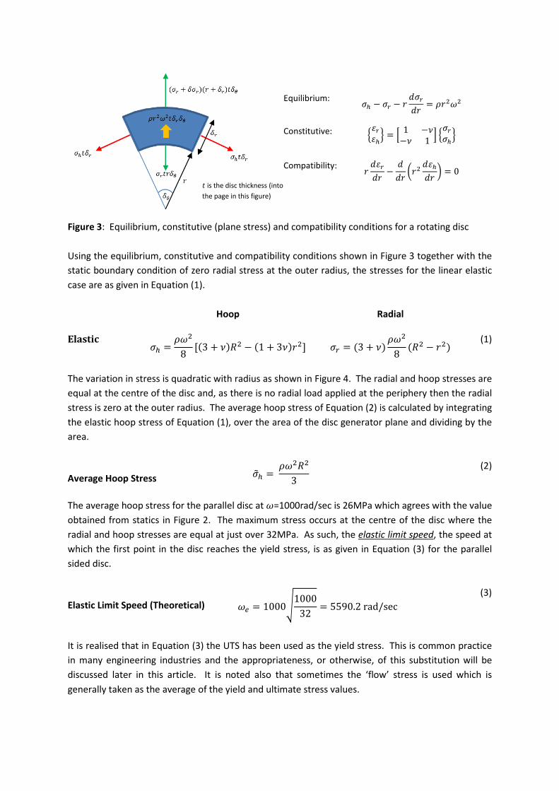
Figure 3: Equilibrium, constitutive (plane stress) and compatibility conditions for a rotating disc
Using the equilibrium, constitutive and compatibility conditions shown in Figure 3 together with the
static boundary condition of zero radial stress at the outer radius, the stresses for the linear elastic
case are as given in Equation (1).
Hoop Radial
Elastic �� ���8 [�3 + ���� − �1 + 3��"�] �$ �3 + �� ���8 ��� − "�� (1)
The variation in stress is quadratic with radius as shown in Figure 4. The radial and hoop stresses are
equal at the centre of the disc and, as there is no radial load applied at the periphery then the radial
stress is zero at the outer radius. The average hoop stress of Equation (2) is calculated by integrating
the elastic hoop stress of Equation (1), over the area of the disc generator plane and dividing by the
area.
Average Hoop Stress ��� �����3 (2)
The average hoop stress for the parallel disc at �=1000rad/sec is 26MPa which agrees with the value
obtained from statics in Figure 2. The maximum stress occurs at the centre of the disc where the
radial and hoop stresses are equal at just over 32MPa. As such, the elastic limit speed, the speed at
which the first point in the disc reaches the yield stress, is as given in Equation (3) for the parallel
sided disc.
Elastic Limit Speed (Theoretical) �& 1000(100032 5590.2rad/sec (3)
It is realised that in Equation (3) the UTS has been used as the yield stress. This is common practice
in many engineering industries and the appropriateness, or otherwise, of this substitution will be
discussed later in this article. It is noted also that sometimes the ‘flow’ stress is used which is
generally taken as the average of the yield and ultimate stress values.
Equilibrium: �� − �$ − " 4�$4" �"���
Constitutive:
56$6�7 8 1 −�−� 1 9 5�$��7
Compatibility: " 46$4" − 44" :"� 46�4" ; 0
< is the disc thickness (into
the page in this figure)

Theoretical Plastic Solution
A plastic solution for the rotating disc may be obtained through the lower bound theorem of
plasticity which requires an equilibrating stress field that nowhere violates the yield criterion. The
linear elastic solution is an equilibrating stress field and can be considered as a particular solution for
the plastic problem. A hyperstatic or self-balancing stress field may be added to the particular
solution so as to maximise the load carrying capacity of the disc and provide a total solution that
does not violate the yield criterion. A hint has already been given regarding the nature of the total
solution at collapse in the empirical studies by Robinson where he showed a good correlation
between the average hoop stress at burst and the ultimate strength of the material. As such the
hoop component of a candidate hyperstatic solution would be the difference between the average
hoop stress and that of the particular (elastic) solution as shown in Equation (4).
Hyperstatic hoop stress ��= ��� − �� (4)
The corresponding radial component of the hyperstatic solution can be obtained by substituting the
hoop stress into the homogeneous form of the equilibrium equation, i.e., the form with no loading
term, and also satisfying the static condition of zero stress at the outer radius as shown in Equation
(5).
Hoop Radial
Hyperstatic ��= ���24 �1 + 3���3"� − ��� �$= ���24 �1 + 3���"� − ��� (5)
The various parts, particular and hyperstatic, of the total solution are shown, as a function of radius
in Figure 4 together with the elastic and plastic stress as they lie within the Tresca yield criterion.
The Total stress is the sum of the Particular and the Hyperstatic stresses and these are shown in the left-hand figure for a speed of
1000rad/sec. The right-hand figure shows the Tresca yield criterion at 1000MPa yield stress. The total stress at the elastic and plastic limit
speeds are plotted on the diagram as yellow lines with the top point corresponding to the centre of the disc (where radial and hoop
stresses are equal) and the bottom point to the periphery where the radial stress is zero.
Figure 4: Development of a theoretical lower bound solution

The plastic theory outlined above follows closely that of reference [4], but has been cast in the form
of an equilibrium analysis. The plastic limit speed is given in Equation [6].
Plastic Limit Speed (Theoretical) �? 1000(100026 6201.7rad/sec
(6)
Thus, for the Tresca yield criterion, all points of the disc are at yield and the proposed lower bound
solution is then also the theoretically exact solution, i.e., the disc cannot take any more load. The
increase in disc speed from the elastic to the plastic limit speed is just over 10%:
Plastic/Elastic Limit Speed Ratio (Theoretical)
�?�& 6201.75590.2 ≅ 1.10
(7)
The two preceding sections have developed the elastic and plastic solutions for parallel sided
rotating discs. This theory shows that for a rigid, perfectly plastic material which obeys the Tresca
yield criterion, the average hoop stress calculated from an elastic solution can be used to predict the
burst speed of a parallel sided rotating disc.
Finite Element Models
The geometry of a disc has many forms of symmetry that may be utilised in a finite element model.
A solid model might be used of the complete disc but as there is no variation in the stresses in the
circumferential direction a cyclic sector model could be used with symmetry boundary conditions
applied to the sector faces. In a similar manner, a sector model using planar elements might be
used. The most appropriate model though would be an axisymmetric one in which a generator
plane is meshed. Such a model would show any variation in the two main stress components (radial
and hoop) with axial position. Additionally, as the disc has a central plane of symmetry normal to
the axis of rotation it is only necessary to model half of the generator plane as illustrated in Figure 5.
There are three possible finite element models that might be used, solid, planar or axisymmetric. The axisymmetric model is chosen as it
will show the axial variation in the stress and involves no approximation of the circular arc – even higher-order elements are unable to
approximate an arc exactly. As the disc is symmetric about a central plane normal to the axis of rotation only half of the generator plane
needs to be modelled and the addition of symmetry boundary conditions on this plane of symmetry eliminates the axial rigid body
displacement. It is worth pointing out that the possibility of modelling the same problem with different finite element models offers the
engineer an additional way of performing verification. In this case, for example, both solid and axisymmetric models should produce
identical answers provided the engineer had correctly modelled the problem and provided the FE software is sound for both model types;
it is unlikely, although still possible, that a software issue extends to two different finite element models of the same problem.
Figure 5: Finite element models for the disc
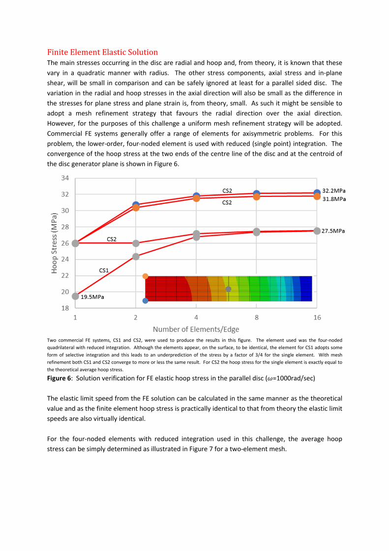
Finite Element Elastic Solution
The main stresses occurring in the disc are radial and hoop and, from theory, it is known that these
vary in a quadratic manner with radius. The other stress components, axial stress and in-plane
shear, will be small in comparison and can be safely ignored at least for a parallel sided disc. The
variation in the radial and hoop stresses in the axial direction will also be small as the difference in
the stresses for plane stress and plane strain is, from theory, small. As such it might be sensible to
adopt a mesh refinement strategy that favours the radial direction over the axial direction.
However, for the purposes of this challenge a uniform mesh refinement strategy will be adopted.
Commercial FE systems generally offer a range of elements for axisymmetric problems. For this
problem, the lower-order, four-noded element is used with reduced (single point) integration. The
convergence of the hoop stress at the two ends of the centre line of the disc and at the centroid of
the disc generator plane is shown in Figure 6.
Two commercial FE systems, CS1 and CS2, were used to produce the results in this figure. The element used was the four-noded
quadrilateral with reduced integration. Although the elements appear, on the surface, to be identical, the element for CS1 adopts some
form of selective integration and this leads to an underprediction of the stress by a factor of 3/4 for the single element. With mesh
refinement both CS1 and CS2 converge to more or less the same result. For CS2 the hoop stress for the single element is exactly equal to
the theoretical average hoop stress.
Figure 6: Solution verification for FE elastic hoop stress in the parallel disc (�=1000rad/sec)
The elastic limit speed from the FE solution can be calculated in the same manner as the theoretical
value and as the finite element hoop stress is practically identical to that from theory the elastic limit
speeds are also virtually identical.
For the four-noded elements with reduced integration used in this challenge, the average hoop
stress can be simply determined as illustrated in Figure 7 for a two-element mesh.
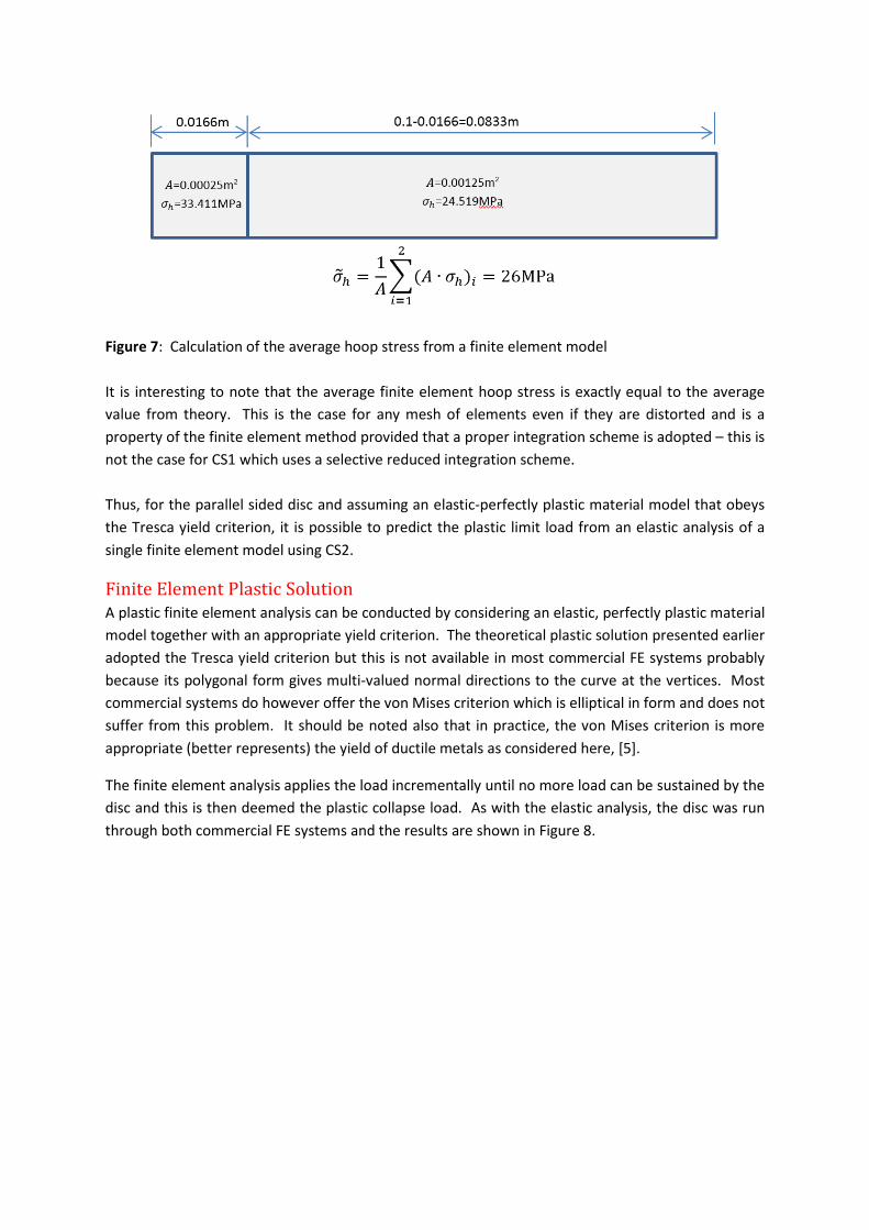
Figure 7: Calculation of the average hoop stress from a finite element model
It is interesting to note that the average finite element hoop stress is exactly equal to the average
value from theory. This is the case for any mesh of elements even if they are distorted and is a
property of the finite element method provided that a proper integration scheme is adopted – this is
not the case for CS1 which uses a selective reduced integration scheme.
Thus, for the parallel sided disc and assuming an elastic-perfectly plastic material model that obeys
the Tresca yield criterion, it is possible to predict the plastic limit load from an elastic analysis of a
single finite element model using CS2.
Finite Element Plastic Solution
A plastic finite element analysis can be conducted by considering an elastic, perfectly plastic material
model together with an appropriate yield criterion. The theoretical plastic solution presented earlier
adopted the Tresca yield criterion but this is not available in most commercial FE systems probably
because its polygonal form gives multi-valued normal directions to the curve at the vertices. Most
commercial systems do however offer the von Mises criterion which is elliptical in form and does not
suffer from this problem. It should be noted also that in practice, the von Mises criterion is more
appropriate (better represents) the yield of ductile metals as considered here, [5].
The finite element analysis applies the load incrementally until no more load can be sustained by the
disc and this is then deemed the plastic collapse load. As with the elastic analysis, the disc was run
through both commercial FE systems and the results are shown in Figure 8.
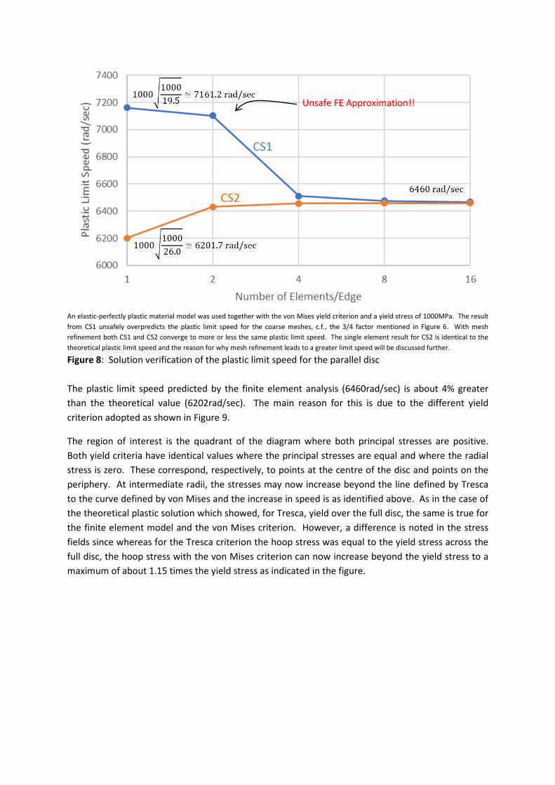
An elastic-perfectly plastic material model was used together with the von Mises yield criterion and a yield stress of 1000MPa. The result
from CS1 unsafely overpredicts the plastic limit speed for the coarse meshes, c.f., the 3/4 factor mentioned in Figure 6. With mesh
refinement both CS1 and CS2 converge to more or less the same plastic limit speed. The single element result for CS2 is identical to the
theoretical plastic limit speed and the reason for why mesh refinement leads to a greater limit speed will be discussed further.
Figure 8: Solution verification of the plastic limit speed for the parallel disc
The plastic limit speed predicted by the finite element analysis (6460rad/sec) is about 4% greater
than the theoretical value (6202rad/sec). The main reason for this is due to the different yield
criterion adopted as shown in Figure 9.
The region of interest is the quadrant of the diagram where both principal stresses are positive.
Both yield criteria have identical values where the principal stresses are equal and where the radial
stress is zero. These correspond, respectively, to points at the centre of the disc and points on the
periphery. At intermediate radii, the stresses may now increase beyond the line defined by Tresca
to the curve defined by von Mises and the increase in speed is as identified above. As in the case of
the theoretical plastic solution which showed, for Tresca, yield over the full disc, the same is true for
the finite element model and the von Mises criterion. However, a difference is noted in the stress
fields since whereas for the Tresca criterion the hoop stress was equal to the yield stress across the
full disc, the hoop stress with the von Mises criterion can now increase beyond the yield stress to a
maximum of about 1.15 times the yield stress as indicated in the figure.
Unsafe FE Approximation!!

The nodal principal stresses from a 16x16 element mesh are normalised with the yield stress (1000MPa) and plotted as points on the
diagram. The polygonal yield criterion of Tresca is shown in blue and the elliptical von Mises criterion in black. The radial stress does not
exceed the yield stress (1000MPa) but the hoop stress is able to exceed this by about 15% and this corresponds to the increase allowed
when adopting the von Mises yield criterion over the Tresca criterion.
Figure 9: Normalised principal stresses for the parallel disc
In writing this response it was discovered that in CS2 the Tresca yield criterion could be simulated
using the Mohr-Coulomb criterion with the friction and dilation angles set to zero and the cohesion
yield stress set to half the material yield stress. This yield criterion is non-associative leading to a
non-symmetric stiffness matrix and the requirement for an appropriate solver. However, the results
produced provide a plastic limit speed identical to the theoretical solution presented earlier in this
response.
Tapered Challenge Disc
The challenge included, in addition to the parallel sided disc, a tapered disc for consideration. It is
likely that as the taper in the disc increases the solution will begin to differ from that for the parallel
sided disc and this is the case as shown in Figure 10 which presents the results of a parametric study
where the taper of the disc is increased by increasing the central axial thickness for a fixed axial
thickness at the disc periphery.
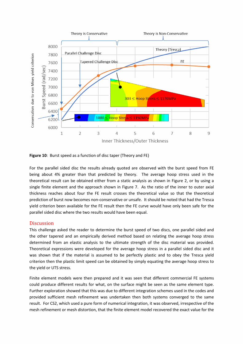
Figure 10: Burst speed as a function of disc taper (Theory and FE)
For the parallel sided disc the results already quoted are observed with the burst speed from FE
being about 4% greater than that predicted by theory. The average hoop stress used in the
theoretical result can be obtained either from a static analysis as shown in Figure 2, or by using a
single finite element and the approach shown in Figure 7. As the ratio of the inner to outer axial
thickness reaches about four the FE result crosses the theoretical value so that the theoretical
prediction of burst now becomes non-conservative or unsafe. It should be noted that had the Tresca
yield criterion been available for the FE result then the FE curve would have only been safe for the
parallel sided disc where the two results would have been equal.
Discussion
This challenge asked the reader to determine the burst speed of two discs, one parallel sided and
the other tapered and an empirically derived method based on relating the average hoop stress
determined from an elastic analysis to the ultimate strength of the disc material was provided.
Theoretical expressions were developed for the average hoop stress in a parallel sided disc and it
was shown that if the material is assumed to be perfectly plastic and to obey the Tresca yield
criterion then the plastic limit speed can be obtained by simply equating the average hoop stress to
the yield or UTS stress.
Finite element models were then prepared and it was seen that different commercial FE systems
could produce different results for what, on the surface might be seen as the same element type.
Further exploration showed that this was due to different integration schemes used in the codes and
provided sufficient mesh refinement was undertaken then both systems converged to the same
result. For CS2, which used a pure form of numerical integration, it was observed, irrespective of the
mesh refinement or mesh distortion, that the finite element model recovered the exact value for the
average hoop stress. Finite element analyses were conducted using an elastic-perfectly plastic
material model together with the von Mises yield criterion. The elliptical yield criterion of von Mises
allows the hoop stress to develop beyond the yield stress by about 15% and this leads to an increase
in the predicted burst speed of about 4% over the Tresca criterion.
The tapered disc was then considered and it was seen that the empirical relationship presented in
the challenge broke down soon after the disc moved away from the parallel sided geometric form.
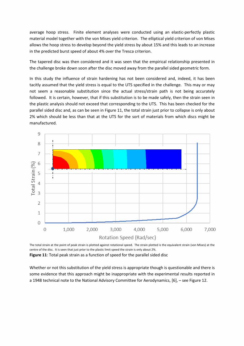
In this study the influence of strain hardening has not been considered and, indeed, it has been
tacitly assumed that the yield stress is equal to the UTS specified in the challenge. This may or may
not seem a reasonable substitution since the actual stress/strain path is not being accurately
followed. It is certain, however, that if this substitution is to be made safely, then the strain seen in
the plastic analysis should not exceed that corresponding to the UTS. This has been checked for the
parallel sided disc and, as can be seen in Figure 11, the total strain just prior to collapse is only about
2% which should be less than that at the UTS for the sort of materials from which discs might be
manufactured.
The total strain at the point of peak strain is plotted against rotational speed. The strain plotted is the equivalent strain (von Mises) at the
centre of the disc. It is seen that just prior to the plastic limit speed the strain is only about 2%.
Figure 11: Total peak strain as a function of speed for the parallel sided disc
Whether or not this substitution of the yield stress is appropriate though is questionable and there is
some evidence that this approach might be inappropriate with the experimental results reported in
a 1948 technical note to the National Advisory Committee for Aerodynamics, [6], – see Figure 12.
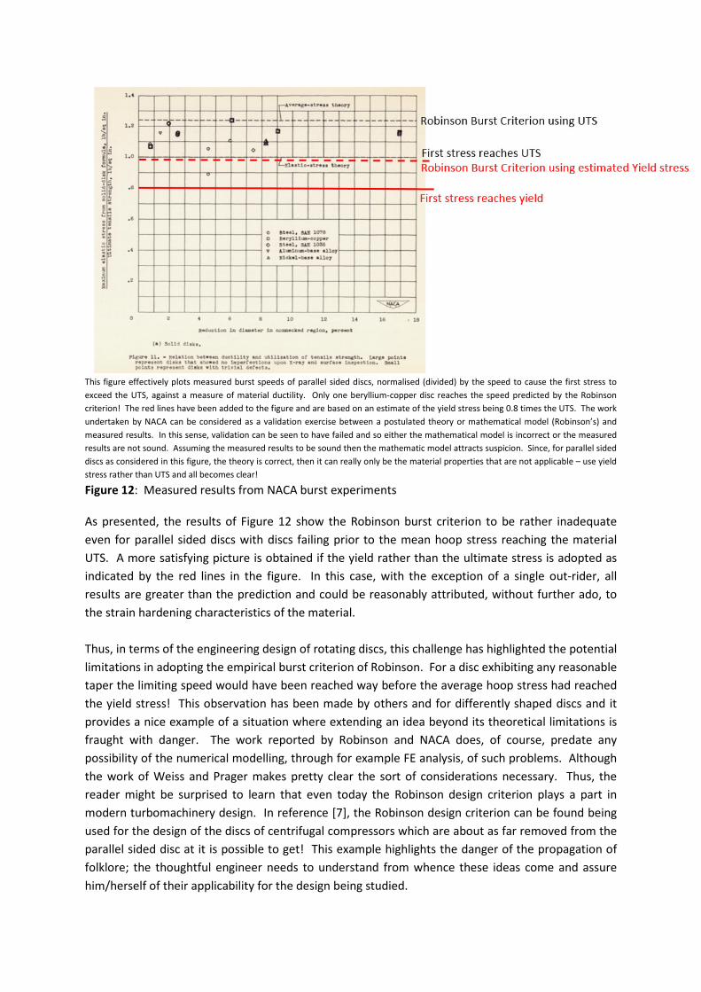
This figure effectively plots measured burst speeds of parallel sided discs, normalised (divided) by the speed to cause the first stress to
exceed the UTS, against a measure of material ductility. Only one beryllium-copper disc reaches the speed predicted by the Robinson
criterion! The red lines have been added to the figure and are based on an estimate of the yield stress being 0.8 times the UTS. The work
undertaken by NACA can be considered as a validation exercise between a postulated theory or mathematical model (Robinson’s) and
measured results. In this sense, validation can be seen to have failed and so either the mathematical model is incorrect or the measured
results are not sound. Assuming the measured results to be sound then the mathematic model attracts suspicion. Since, for parallel sided
discs as considered in this figure, the theory is correct, then it can really only be the material properties that are not applicable – use yield
stress rather than UTS and all becomes clear!
Figure 12: Measured results from NACA burst experiments
As presented, the results of Figure 12 show the Robinson burst criterion to be rather inadequate
even for parallel sided discs with discs failing prior to the mean hoop stress reaching the material
UTS. A more satisfying picture is obtained if the yield rather than the ultimate stress is adopted as
indicated by the red lines in the figure. In this case, with the exception of a single out-rider, all
results are greater than the prediction and could be reasonably attributed, without further ado, to
the strain hardening characteristics of the material.
Thus, in terms of the engineering design of rotating discs, this challenge has highlighted the potential
limitations in adopting the empirical burst criterion of Robinson. For a disc exhibiting any reasonable
taper the limiting speed would have been reached way before the average hoop stress had reached
the yield stress! This observation has been made by others and for differently shaped discs and it
provides a nice example of a situation where extending an idea beyond its theoretical limitations is
fraught with danger. The work reported by Robinson and NACA does, of course, predate any
possibility of the numerical modelling, through for example FE analysis, of such problems. Although
the work of Weiss and Prager makes pretty clear the sort of considerations necessary. Thus, the
reader might be surprised to learn that even today the Robinson design criterion plays a part in
modern turbomachinery design. In reference [7], the Robinson design criterion can be found being
used for the design of the discs of centrifugal compressors which are about as far removed from the
parallel sided disc at it is possible to get! This example highlights the danger of the propagation of
folklore; the thoughtful engineer needs to understand from whence these ideas come and assure
him/herself of their applicability for the design being studied.
Acknowledgements
The author would like to thank Ian Symington, Technical Officer at NAFEMS, and Alan Prior and his
colleagues at Simulia for assisting the him with some of the technical hurdles involved in the plastic
analysis of the rotating discs considered in this challenge.
References
[1] Robinson, E., Bursting Tests of Steam-Turbine Disk Wheels, Trans. ASME 66, page 373, 1944.
[2] Stefano Chianese, Safety Factor Against Burst Speed of Turbomachinery Rotating Disks, MSc
Thesis, University of Illinois, Chicago, 2013.
http://indigo.uic.edu/handle/10027/10185
[3], Hearn, E.J., Mechanics of Materials, Volume II, 3rd Edition, Butterworth-Heinemann, 2000.
[4] Weiss, H.J., & Prager, W., The Bursting Speed of a Rotating Plastic Disc, Office of Naval Research,
Technical Report Number 96, September, 1953.
http://www.dtic.mil/dtic/tr/fulltext/u2/016990.pdf
[5] Taylor, G.I., Quinney, H., The Plastic Distortion of Metals, Philosophical Transactions of the Royal
Society of London, Series A, Vol. 230, pp. 323-362, 1932.
www.jstor.org/stable/91233
[6] Holms, A.G., & Jenkins, J.E., Effect of Strength and Ductility on the Burst Characteristics of
Rotating Discs, Technical Note 1667, National Advisory Committee for Aeronautics, Cleveland, Ohio,
July 1948.
https://ntrs.nasa.gov/archive/nasa/casi.ntrs.nasa.gov/19930082292.pdf
[7] Robinson, C., Casey, M. and Woods I., An Integrated Approach to the Aero-Mechanical
Optimisation of Turbo-Compressors, in Current Trends in Design and Computation of
Turbomachinery, 2011.
http://www.pcaeng.co.uk/library/Publications/WhitePapers/turbostroje-2011_PCA-ENG.pdf
NAFEMS PSE Competencies Identifier
ID Competency Statement FEAkn8 List the requirements for an axisymmetric analysis to be valid.
FEAkn11 Sketch problems showing the various form of symmetry.
FEAkn12 List the advantages of using symmetry.
FEAco17 Explain the process of Gaussian Quadrature and the terms Reduced Integration, Shear Locking and Mechanisms.
FEAco31 Explain why most finite elements do not represent a circular boundary exactly …
FEAco35 Discuss the terms Validation and Verification and highlight their importance.
FEAap3 Illustrate the approximate nature of finite element analysis, through examples chosen from your industry sector.
FEAap14 Carry out sensitivity studies.
MESMco3 Explain the significance of the terms Equilibrium, Compatibility and Constitutive Relations.
MESMco14 Provide examples of Plane Stress and Plane Strain.
MESMco15 Explain the Tresca and von Mises Failure Criteria in 2D, sketching the failure surface.
MESMco16 Discuss the stress states that give rise to maximum differences between the Tresca and von Mises criteria.
MASco11 Discuss the terms elastic-perfectly plastic, kinematic hardening, isotropic hardening, Bauschinger effect, hysteresis loop.
NGECco4 Outline how large displacements, plasticity and instability can interact in a collapse scenario.
NGECap2 Conduct large displacement analyses.
PLASco4 Explain the terms Limit Load and Plastic Collapse Load and explain why the latter is often a misnomer.
PLASco5 Explain the terms First Yield Load, Ultimate Load and Plastic Instability Load.
PLASap2 Use FEA to determine Limit Loads for a range of components.
PLASap3 Use FEA to determine Plastic Collapse Loads for a range of components.
SIMMkn6 V&V - State simulation V&V principles.
SIMMco7 V&V - Explain the term solution verification.
SIMMco8 V&V - Explain the term code verification.
![The Complementary Functions Method (CFM) Solution to the ...thermal stress analysis of curvilinearly orthotropic rotating discs. Çallıoğlu et al. [2 2 , 23 ] analytically investigated](https://static.fdocuments.in/doc/165x107/60ae0c70bc9200544f4a193c/the-complementary-functions-method-cfm-solution-to-the-thermal-stress-analysis.jpg)