Effect of minimum quantity lubrication strategies on ...
7
REGULAR ARTICLE Effect of minimum quantity lubrication strategies on tribological study of simulated machining operation Sana Werda 1,* , Arnaud Duchosal 2 , Guénhaël Le Quilliec 2 , Antoine Morandeau 3 , and René Leroy 2 1 Université Bordeaux, I2M, UMR 5295, 351 cours de la Libération, 33400 Talence, France 2 Université Tours, Université Orléans, INSA Centre Val de Loire, Laboratoire de Mécanique Gabriel Lamé Polytech Tours, 7 avenue Marcel Dassault, 37200 Tours, France 3 Sandvik Coromant-CEROC, rue Henri Garih, 37230 Fondettes, France Received: 3 April 2019 / Accepted: 26 September 2019 Abstract. The main aim of this paper was to reproduce the frictional behaviour that occurred in milling with a pin-on-cylinder system. Three different tribological tests were conducted reproducing friction phenomenon that happened in three machining conditions: (i) dry rubbing, representing the dry machining condition, (ii) MQL applied to front face rubbing which was similar to milling with MQL applied on the insert rake face and (iii) MQL applied to rear end rubbing which was similar to milling with MQL applied on flank face. Tribological tests were carried out with coated tungsten carbide pins rubbing on X100CrMoV5 steel cylinder. Apparent coefficient of friction, adhesion area and heat flux transmitted to the pin were analysed. It has been shown that MQL rear end rubbing provided a lower adhesion area and lower apparent coefficient of friction than with MQL front face rubbing. Furthermore, MQL rear end rubbing resulted in a greater cooling ability. These findings helped to explain why better results were obtained with MQL flank face lubrication in milling compared to MQL rake face lubrication. Keywords: Minimum quantity lubrication / pin on cylinder / friction / adhesion / heat flux 1 Introduction Minimum Quantity Lubrication (MQL) was an environ- ment-friendly and economically beneficial method in machining [1–3]. Small amount of bio-degradable oil mist was sprayed on the cutting zone with pressurized air in order to improve machinability [4–6]. The extreme reduction in lubricant quantities resulted in nearly dry workpieces and chips. Several studies highlighted the benefit of using inner channels in order to specifically spray the cutting area [1,6–10]. This novel technique ensured precise lubrication supply directly to the cutting zone [11]. The difficulty for the oil mist to reach the cutting edges during machining was the main problem of this technique. The chip formation and the extreme contact between tool and workpiece limited the lubrication process [12–14]. In this context, a new spray method able to successfully lubricate the cutting edges needed to be considered. Some authors have turned to insert flank face lubrication and compared it to conventional rake face lubrication. Masoudi et al. investigated the influence of MQL nozzle position on cutting forces and surface roughness during turning of AISI 1045 steel. The rake face sprayed by MQL nozzle gave lower cutting forces and lower roughness than a single nozzle on the flank face [15]. On another side, Ekinovic et al. investigated the influence of MQL rake face and flank face separately. Both lubrication methods gave the same results in terms of cutting forces. As a result, the position of the nozzle does not significantly affect the cutting forces during MQL turning of carbon steel St52-3 [16]. However, another study compared the influence of either simultaneously lubricating both faces, or solely on the flank face or rake face in finish turning of AISI 1045 steel with high pressure coolant. The longest tool lives were obtained when fluid was applied on the flank face with high pressure and low flow rate, or on both faces simultaneously with high pressure and high flow rate [17]. Banerjee et al. investigated an experimental system in end-milling Ti-6Al-4V wherein two separate supply systems provide an oil–air mixture at the rake and flank faces. The flow parameters such as proportion of oil are individually controlled at the rake and flank faces individually. It was found that injecting the oil fully at the flank face is beneficial for providing the best surface finish and decreasing tool wear [3]. Furthermore, Attanasio et al. * e-mail: [email protected] Mechanics & Industry 20, 624 (2019) © S. Werda et al., published by EDP Sciences 2019 https://doi.org/10.1051/meca/2019057 Mechanics & Industry Available online at: www.mechanics-industry.org This is an Open Access article distributed under the terms of the Creative Commons Attribution License (http://creativecommons.org/licenses/by/4.0), which permits unrestricted use, distribution, and reproduction in any medium, provided the original work is properly cited.
Transcript of Effect of minimum quantity lubrication strategies on ...

Mechanics & Industry 20, 624 (2019)© S. Werda et al., published by EDP Sciences 2019https://doi.org/10.1051/meca/2019057
Mechanics&IndustryAvailable online at:
www.mechanics-industry.org
REGULAR ARTICLE
Effect of minimum quantity lubrication strategies on tribologicalstudy of simulated machining operationSana Werda1,*, Arnaud Duchosal2, Guénhaël Le Quilliec2, Antoine Morandeau3, and René Leroy2
1 Université Bordeaux, I2M, UMR 5295, 351 cours de la Libération, 33400 Talence, France2 Université Tours, Université Orléans, INSA Centre Val de Loire, Laboratoire de Mécanique Gabriel Lamé Polytech Tours,7 avenue Marcel Dassault, 37200 Tours, France
3 Sandvik Coromant-CEROC, rue Henri Garih, 37230 Fondettes, France
* e-mail: s
This is an O
Received: 3 April 2019 / Accepted: 26 September 2019
Abstract. The main aim of this paper was to reproduce the frictional behaviour that occurred in milling with apin-on-cylinder system. Three different tribological tests were conducted reproducing friction phenomenon thathappened in three machining conditions: (i) dry rubbing, representing the dry machining condition, (ii) MQLapplied to front face rubbing which was similar tomilling withMQL applied on the insert rake face and (iii)MQLapplied to rear end rubbing which was similar to milling with MQL applied on flank face. Tribological tests werecarried out with coated tungsten carbide pins rubbing on X100CrMoV5 steel cylinder. Apparent coefficient offriction, adhesion area and heat flux transmitted to the pin were analysed. It has been shown that MQL rear endrubbing provided a lower adhesion area and lower apparent coefficient of friction than with MQL front facerubbing. Furthermore, MQL rear end rubbing resulted in a greater cooling ability. These findings helped toexplain why better results were obtained with MQL flank face lubrication in milling compared to MQL rake facelubrication.
Keywords: Minimum quantity lubrication / pin on cylinder / friction / adhesion / heat flux
1 Introduction
Minimum Quantity Lubrication (MQL) was an environ-ment-friendly and economically beneficial method inmachining [1–3]. Small amount of bio-degradable oil mistwas sprayed on the cutting zone with pressurized air inorder to improve machinability [4–6]. The extremereduction in lubricant quantities resulted in nearly dryworkpieces and chips. Several studies highlighted thebenefit of using inner channels in order to specifically spraythe cutting area [1,6–10]. This novel technique ensuredprecise lubrication supply directly to the cutting zone [11].The difficulty for the oil mist to reach the cutting edgesduring machining was the main problem of this technique.The chip formation and the extreme contact between tooland workpiece limited the lubrication process [12–14]. Inthis context, a new spray method able to successfullylubricate the cutting edges needed to be considered.
Some authors have turned to insert flank facelubrication and compared it to conventional rake facelubrication. Masoudi et al. investigated the influence of
pen Access article distributed under the terms of the Creative Comwhich permits unrestricted use, distribution, and reproduction
MQL nozzle position on cutting forces and surfaceroughness during turning of AISI 1045 steel. The rakeface sprayed by MQL nozzle gave lower cutting forces andlower roughness than a single nozzle on the flank face [15].On another side, Ekinovic et al. investigated the influenceof MQL rake face and flank face separately. Bothlubrication methods gave the same results in terms ofcutting forces. As a result, the position of the nozzle doesnot significantly affect the cutting forces during MQLturning of carbon steel St52-3 [16]. However, another studycompared the influence of either simultaneously lubricatingboth faces, or solely on the flank face or rake face in finishturning of AISI 1045 steel with high pressure coolant. Thelongest tool lives were obtained when fluid was applied onthe flank face with high pressure and low flow rate, or onboth faces simultaneously with high pressure and high flowrate [17]. Banerjee et al. investigated an experimentalsystem in end-milling Ti-6Al-4V wherein two separatesupply systems provide an oil–air mixture at the rake andflank faces. The flow parameters such as proportion of oilare individually controlled at the rake and flank facesindividually. It was found that injecting the oil fully at theflank face is beneficial for providing the best surface finishand decreasing tool wear [3]. Furthermore, Attanasio et al.
mons Attribution License (http://creativecommons.org/licenses/by/4.0),in any medium, provided the original work is properly cited.

Fig. 1. (a) Illustration of the pin dimensions, the location of theholes to measure temperature and (b) the pin fixation details.
2 S. Werda et al.: Mechanics & Industry 20, 624 (2019)
compared dry machining with only rake face and flank faceMQL lubrication during turning 100Cr6 steel [18]. Dry andMQL cutting with rake face lubrication presented similartool life. However, whatever the tested feed rate, better toollife up to 20% was obtained with MQL applied on flankface. Moreover, after SEM analysis of the inserts, lubricantcomponents were observed on the flank face (calcium andsulphide), but no chemical components of the lubricantwere detected on the rake face. Furthermore, the study ofHadad et al. led to surface roughness decrease up to 15%when turning AISI 4140 steel with MQL flank facelubrication compared to rake face lubrication [19]. Finally,in a turning study of SCM440H, the surface roughnessof the workpiece was improved by the oil mist suppliedto the flank face over a large cutting speed range of30–300mmin�1 compared to rake face lubrication [20].Recently, in previous experiments [21], the influence ofMQL lubrication position inmilling X100CrMoV5 steel hasbeen investigated. Results showed that the efficiency ofMQL process was ensured when applied to flank face. Thelubricant penetrated the tool/workpiece interface whichled to a lower surface roughness of about 40% and bettertool life of 10% compared to MQL applied on rake face [21].From the above studies, flank face lubrication is generally abetter choice than rake face lubrication in turning and inmilling. Nevertheless, there is an important lack offundamental understanding of the phenomena occurringat the tool–chip and at the tool–workpiece interfaces [22].In order to understand the wear mechanisms and suchdifferent behaviours when MQL was applied on rake faceand flank face, tribological tests need to be considered.Hence, a tribological study was represented in this articleto determine frictional behaviour regarding milling strate-gy to investigate the results in the previous study [21]. Twotypes of tribometers can be used: closed tribometers andopened tribometers. Closed tribometers processes con-sisted on a pin with a flat or spherical tip in friction againsta disc, a cylinder or a plate. The pin rubbed continuously onthe same track in order to determine the wear mechanismsof the pin. But, this pin-on-disc process did not consider anew rubbing friction surface occurred in milling machining[23,24]. In order to represent the real frictional contactduringmilling, opened tribometers were used to offer bettersimilarity with machining since pins were rubbed over aconstantly new surface.
The opened systems of Zemzemi (axial tribometer) andBonnet (radial tribometer) were therefore found to beeffective in simulating the tribological conditions similar tothose occurring at the tool-chip and tool-material inter-faces. Both of these tribometers reached a contact pressureof 3GPa [23,24]. The results obtained with the Bonnet’stribometer showed coherent results in terms of apparentcoefficient of friction. More specifically, results with MQLshowed lower coefficient compared to dry tests [14,25,26].Moreover, this tribometer provided the opportunity for awide range of rubbing speeds [24]. From these previousresults, the choice focused on the tribometer type of Bonnetand the tribological study presented in this paper wasinvestigated with radial pin-on-cylinder tests.
The main aim of this article was to investigate twoMQL conditions (Flank Face and Rake Face lubrication)
met in milling [21] through tribological study in order tounderstand the mechanisms explaining better results withthe MQL flank face. Three different tribological pin-on-cylinder tests were conducted: dry rubbing as a referencecondition, MQL applied to front face rubbing and MQLapplied to rear end rubbing. These tests were carried outwith tungsten carbide pins grade 4240 from SandvikCoromant supplier rubbing on X100CrMoV5 steel cylin-der. The effects of lubrication configurations were analysedin terms of apparent coefficient of friction, adhesion areaand heat flux transmitted to the pin.
2 Experimental details
In order to understand the friction mechanisms during facemilling mould steel material (X100CrMoV5 type) whenusing MQL assistance, some tribological tests wereperformed on pin-on-cylinder technique. Due to theindustrial context, pins were taken as the same as thecarbide inserts and coating used in milling strategy fromprevious study [21].
2.1 Materials and measurement
A 4240 grade tungsten carbide hemispherical head pinswith MTCVD Al2O3 coating were used in this study. Allthe pins had 40mm length and Ø 8mm with a measuredsurface roughness of 0.2mm. The surface roughness hasbeen measured by a 3D profilometer using VEECOsoftware. The hemispherical head had 17mm radius(Fig. 1a).
All pins were achieved with two holes of Ø 1mm inorder to measure temperature. The holes were located at1mm and 4mm from the hemispherical head of the pin, as

Table 1. Chemical composition of the X100CrMoV5.
Chemical components Cr Mo V C Si Mn P S
Containing (in wt.%) 5.3 1.1 0.20 1 0.3 0.70 �0.025 �0.025
S. Werda et al.: Mechanics & Industry 20, 624 (2019) 3
shown in Figure 1a. Temperatures were obtained withØ 0.13mm K-type thermocouples connected to NationalInstruments NI USB-9162 equipment.
X100CrMoV5 mould steel was used in this study as acylindrical bar, with a cross section of Ø 80mm and alength of 500mm. Chemical composition of the cylindri-cal bar is given in Table 1. During the frictional test only396mm length was considered. After each frictional test,the cylindrical bar was longitudinally turned with acutting depth of 0.1mm in order to remove theplastically affected layer induced by the previous frictiontest and a new pin is fixed. Some alcohol was applied toremove any lubricant residue. The experimental test wasset on digitally controlled Victor Vturn-A26 turningmachine.
Fig. 2. Illustration of the MQL application configurations (a) infront face rubbing (by analogy with MQL rake face) and (b) inrear end rubbing (by analogy with MQL flank face).
2.2 Tribological test configurations
Tribological studies were conducted in order to betterunderstand the differences between the tool life results inmilling machining configurations and to reproduce lubri-cation with MQL applied on rake face andMQL applied onflank face [21].
Three rubbing configurations were tested to reproducethree machining conditions under different lubrications:
–
Dry rubbing, representing the dry machining condition. – MQL applied to front face rubbing (MQL FFR) whichwas the configuration representing milling with MQL onthe rake face (Fig. 2a).–
MQL applied to rear end rubbing (MQL RER): thisconfiguration representedmilling withMQL on flank face(Fig. 2b).All the tests were repeated at least three times.In order to be in the same configuration as in
machining when using MQL by inner canalizations onthe tool holder [21], Ø1.6mm nozzle is oriented at 30°from the contact plan. The MQL nozzle was located alsoin the same distance (7mm as shown in Fig. 1b) and atthe same side of the pin. The applied MQL regarding tomilling conditions observed in the previous study (rakeface or flank face) is governed by the rotating direction ofthe bar.
The oil mist was generated by an external mixingdevice (Lubrilean Digital Super device developed bySKF) supplied by 7 bar air pressure. Digital Supersoftware can control the oil mist device to set the oil mistflow rate at 7ml h�1 with about 27 NL min�1 air flowrate. The selected oil was a synthetic ester PX5130 fromthe supplier Total. The apparent coefficient of frictionand the temperature were measured during 396 mm
long bar. The first quarter of test period was notconsidered until the temperature was stabilized. Thecontact forces were measured during the test using aKISTLER type 9129AA dynamometer.
The apparent coefficient of friction mapp was calculatedaccording to Coulomb’s law (Eq. (1)).
mapp ¼ Ft
Fn; ð1Þ
where Ft and Fn were respectively the tangential force andthe normal force on the pin. This apparent coefficient offriction could be decomposed into an adhesion friction madhand a plastic deformation friction mdef [27] as shown inequation (2).
mapp ¼ madh þ mdef : ð2Þ
In order to be in the same milling machiningconfiguration, a contact pressure of 1.7GPa was measuredwith the ratio between the cutting force and the contactsurface [21].
4 S. Werda et al.: Mechanics & Industry 20, 624 (2019)
In these tribological tests, the contact pressure has beenevaluated by the Hertz theory described in equation (3) [28]as follows:
Pn ¼ 3 � Fn
2 � p � a2; ð3Þ
where Pnwas the normal pressure of the contact (MPa), Fnwas the measured normal force applied to the pin (N) and awas the contact radius (mm).
This relationship allowed ascertaining of the normalforce to apply [28]. The contact radius was estimated byHertz’s equation (Eq. (4)), as follows:
a ¼ 3 � p � R1 � R2
4 � ðR1 þR2Þ1� v21p � E1
þ 1� v22p � E2
� �� �1=3
; ð4Þ
where Ri, Ei and ni were, respectively, the radius (mm), theYoung modulus (MPa) and the Poisson coefficient of theconsidered materials. The summary of these mechanicalproperties is shown in Table 2. Mechanical properties of thepin are nearly three times higher than the cylinder, whichled to not consider the properties of the coating in thisstudy.
Table 2. Mechanical and geometrical properties ofcontact materials.
YoungmodulusEi (GPa)
Poisson’sratio vi
RadiusRi (mm)
Pin (1) 580 0.24 17Cylinder (2) 210 0.3 40
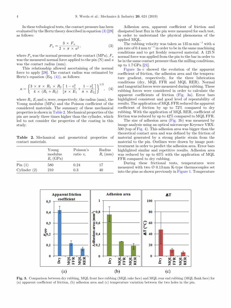
Fig. 3. Comparison between dry rubbing, MQL front face rubbing(a) apparent coefficient of friction, (b) adhesion area and (c) temp
Adhesion area, apparent coefficient of friction anddissipated heat flux in the pin were measured for each test,in order to understand the physical phenomena of theapplied MQL.
The rubbing velocity was taken as 135mmin�1 with apin rate of 0.4mm tr�1 in order to be in the samemachiningconditions and to get freshly removed material. A 125Nnormal force was applied from the pin to the bar in order tobe in the same contact pressure than themilling conditions,up to 1.7GPa [21].
Figure 3a–c showed the evolution of the apparentcoefficient of friction, the adhesion area and the tempera-ture gradient, respectively, for the three lubricationconditions (dry, MQL FFR and MQL RER). Normaland tangential forces were measured during rubbing. Theserubbing forces were considered in order to calculate theapparent coefficients of friction (Fig. 3a). Error barshighlighted consistent and good level of repeatability ofresults. The application ofMQLFFR reduced the apparentcoefficient of friction by up to 72% compared to dryrubbing. With the application of MQL RER, coefficient offriction was reduced by up to 42% compared to MQL FFR.
The size of adhesion area (Fig. 3b) was measured byimage analysis using an optical microscope Keyence VHX-500 (top of Fig. 4). This adhesion area was bigger than thetheoretical contact area and was defined by the friction ofmaterial generated by a strong plastic strain from thematerial to the pin. Outlines were drawn by image post-treatment in order to predict the adhesion area. Error barshighlighted similar and repetitive results. Adhesion areawas reduced by up to 65% with the application of MQLFFR compared to dry rubbing.
During these frictional tests, temperatures weremeasured with two Ø 0.13mm K-type thermocouples setinto the pins as shown previously in Figure 1. Temperature
(MQL rake face) and MQL rear end rubbing (MQL flank face) forerature variation between the two holes in the pin.
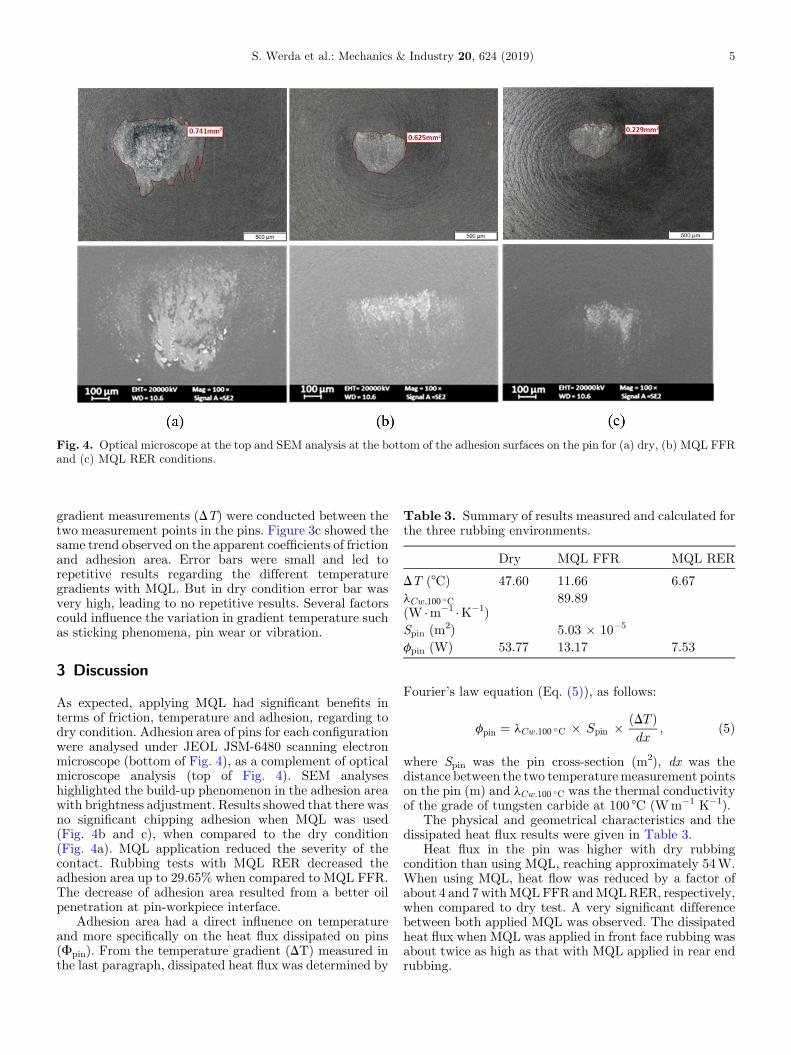
Fig. 4. Optical microscope at the top and SEM analysis at the bottom of the adhesion surfaces on the pin for (a) dry, (b) MQL FFRand (c) MQL RER conditions.
Table 3. Summary of results measured and calculated forthe three rubbing environments.
Dry MQL FFR MQL RER
DT (°C) 47.60 11.66 6.67lCw;100 �C(W ·m�1 ·K�1)
89.89
Spin (m2) 5.03 � 10�5
S. Werda et al.: Mechanics & Industry 20, 624 (2019) 5
gradient measurements (DT) were conducted between thetwo measurement points in the pins. Figure 3c showed thesame trend observed on the apparent coefficients of frictionand adhesion area. Error bars were small and led torepetitive results regarding the different temperaturegradients with MQL. But in dry condition error bar wasvery high, leading to no repetitive results. Several factorscould influence the variation in gradient temperature suchas sticking phenomena, pin wear or vibration.
fpin (W) 53.77 13.17 7.53
3 Discussion
As expected, applying MQL had significant benefits interms of friction, temperature and adhesion, regarding todry condition. Adhesion area of pins for each configurationwere analysed under JEOL JSM-6480 scanning electronmicroscope (bottom of Fig. 4), as a complement of opticalmicroscope analysis (top of Fig. 4). SEM analyseshighlighted the build-up phenomenon in the adhesion areawith brightness adjustment. Results showed that there wasno significant chipping adhesion when MQL was used(Fig. 4b and c), when compared to the dry condition(Fig. 4a). MQL application reduced the severity of thecontact. Rubbing tests with MQL RER decreased theadhesion area up to 29.65% when compared to MQL FFR.The decrease of adhesion area resulted from a better oilpenetration at pin-workpiece interface.
Adhesion area had a direct influence on temperatureand more specifically on the heat flux dissipated on pins(Fpin). From the temperature gradient (DT) measured inthe last paragraph, dissipated heat flux was determined by
Fourier’s law equation (Eq. (5)), as follows:
fpin ¼ lCw:100 �C � Spin � ðDT Þdx
; ð5Þ
where Spin was the pin cross-section (m2), dx was thedistance between the two temperaturemeasurement pointson the pin (m) and lCw:100 �C was the thermal conductivityof the grade of tungsten carbide at 100 °C (Wm�1 K�1).
The physical and geometrical characteristics and thedissipated heat flux results were given in Table 3.
Heat flux in the pin was higher with dry rubbingcondition than using MQL, reaching approximately 54W.When using MQL, heat flow was reduced by a factor ofabout 4 and 7 withMQLFFR andMQLRER, respectively,when compared to dry test. A very significant differencebetween both applied MQL was observed. The dissipatedheat flux when MQL was applied in front face rubbing wasabout twice as high as that with MQL applied in rear endrubbing.

Fig. 5. Identifying lubricated zones during the pin-cylinder testswith MQL.
6 S. Werda et al.: Mechanics & Industry 20, 624 (2019)
Figure 5 showed exactly the physical phenomenaoccurred under different lubrications. During MQLrubbing tests, an MQL environment was created aroundthe cylinder and the pin which are indirectly lubricating.This indicated that some oil mist was sprayed around thepin on the cylinder and some amount of oil was kept on theroughness of the cylinder.WithMQLFFR, the surface thatwill be removed was targeted and directly lubricated by theMQL channel. However, the surface that has just beengenerated was faced on MQL environment, as shown inFigure 5a. Moreover, the created plastic deformationprevents oil from penetrating or lead to a partialpenetration to the frictional surface (presence of oil onroughness of the cylinder). On the other hand, with MQLRER, the surface that will be removed is constantlyindirectly lubricated, because of the MQL environmentdefined in Figure 5. Moreover, the surface that has justbeen generated was targeted with an MQL channel andinstantly lubricated. Hence, MQL RER provided instantlymaximal lubrication, which drastically reduced heat fluxtransmitted to the pin and the coefficient of friction. Withregards to the numerical studies of Bonnet et al. and Rechet al., the maximum stress was located in front face of therubbing contact along the symmetry axis [23,29]. Thecontact pressure in FFR is about 40% higher compared toRER [23,29]. Then, micro-lubricant FFR has somedifficulty to penetrate pin-workpiece interface. On theother hand, by lubricating rear end the rubbing supportinglower pressures will lead to a better penetration of thelubricant, reducing then adhesion area.
By analogy with milling machining [21], MQL appliedon rake face was not as efficient as MQL applied on flankface. Because of the extreme contact in tool-chip interface[30], oil mist did not penetrate as much as required. Betterresults were ensured with MQL applied on flank facebecause of the ability of the oil mist to penetrate the toolworkpiece interface. MQL was an effective alternative todry rubbing, more specifically MQL applied on rear endrubbing (or flank face).
4 Conclusions
Pin-on-cylinder tests have been performed with 4240grade tungsten carbide hemispherical head pin withMTCVD Al2O3 coating on X100CrMoV5 cylinder.
MQL applied on front face rubbing and MQL appliedon rear end rubbing conditions were performed duringthese tests by analogy with previous results studied inmilling machining (MQL applied on flank face and MQLapplied on rake face). Dry tests were conducted asreference. Apparent coefficient of friction, adhesion areaand temperature gradient were analysed. As expected, theinvestigation indicated that the application of MQLoffered better results than with dry condition in terms ofadhesion area and generated heat flux. The applied MQLat pin rear end rubbing reduced coefficient of friction byup to 42% compared to MQL front face rubbing.Moreover, rubbing tests with MQL rear end rubbingdecreased the adhesion area up to 29.65% when comparedto MQL front face rubbing, thanks to a better oilpenetration at pin-workpiece interface. Finally, heat flowwas reduced to almost half with MQL rear end rubbingcompared to front face rubbing. These pin-on-cylindertest observations led to better understand the tribologicalphenomena occurring in machining. MQL applied on frontface rubbing (MQL applied on rake face by analogy withmilling machining) did not penetrate as much as requiredat tool workpiece interface. The generated plasticdeformation area, similar to a chip by analogy withmilling machining, prevented the oil mist penetration. Onthe other side, with MQL applied to rear end rubbing, thelubricated zone supported lower pressures enabling thefluid to penetrate the pin-workpiece interface. Similarly,with machining, higher pressures are located on the insertrake face rather than flank face [30]. Then, oil mistpenetrates more effectively the insert-workpiece interfacerather than insert-chip interface.
This study successfully explained the results obtainedwith MQL flank face (in the previous study [21]) comparedto MQL rake face in terms of tool life and roughness of themachined surface.
In future works, same studies could be conducted withdifferent coating and oil properties on different materials tosee if the results show the same trend. Thus, differentmachining conditions under MQL applied on flank face ondifferent materials could be extended.
The authors would like to thank the cutting tool research centreoperators (CEROC, France), for their support in machining andtribological tests and also gratefully acknowledge SANDVIK-COROMANT for pins supplies.
References
[1] W.A. Khan, N.M. Hoang, B. Tai, W.N.P. Hung, Through-tool minimum quantity lubrication and effect on machin-ability, J. Manuf. Process. 34, 750–757 (2018)
[2] R.R. Srikant, M.M.S. Prasad, M. Amrita, V. Sitaramaraju,Nanofluids as a potential solution for Minimum QuantityLubrication: A review, J. Eng. Manuf. 228, 3–20 (2014)
[3] N. Banerjee, A. Sharma, Improving machining performanceof Ti-6Al-4V through multi-point minimum quantitylubrication method, Proc. Inst. Mech. Eng. Part B J. Eng.Manuf. 233, 321–336 (2018)

S. Werda et al.: Mechanics & Industry 20, 624 (2019) 7
[4] S. Zhang, J.F. Li, Y.W.Wang, Tool life and cutting forces inend milling Inconel 718 under dry and minimum quantitycooling lubrication cutting conditions, J. Clean. Prod. 32,81–87 (2012)
[5] E.A. Rahim, H. Sasahara, Investigation of tool wear andsurface integrity on MQL machining of Ti-6AL-4V usingbiodegradable oil, Proc. Inst. Mech. Eng. Part B J. Eng.Manuf. 225, 1505–1511 (2011)
[6] A.K. Sharma, A.K. Tiwari, A.R. Dixit, Effects of minimumquantity lubrication (MQL) in machining processes usingconventional and nanofluid based cutting fluids: A review, J.Clean. Prod. 127, 1–18 (2016)
[7] A. Duchosal, S. Werda, R. Serra, R. Leroy, H. Hamdi,Numerical modeling and experimental measurement of MQLim- pingement over an insert in a milling tool with innerchannels, Int. J. Mach. Tools Manuf. 94, 37–47 (2015)
[8] R.P. Zeilmann,W.L.Weingaertner, Analysis of temperatureduring drilling of Ti6Al4V with minimal quantity oflubricant, J. Mater. Process. Technol. 179, 124–127 (2006)
[9] T. Aoyama, Development of a mixture supply system formachining with minimal quantity lubrication, CIRP Ann.Manuf. Technol. 51, 289–292 (2002)
[10] A. Duchosal, R. Serra, R. Leroy, Numerical study of the innercanalization geometry optimization in a milling tool used inmicro quantity lubrication, Mech. Ind. 15, 435–442 (2014)
[11] L.N. López de Lacalle, C. Angulo, A. Lamikiz, J.A. Sánchez,Experimental and numerical investigation of the effect ofspray cutting fluids in high speed milling, J. Mater. Process.Technol. 172, 11–15 (2006)
[12] T. Childs, K. Maekawa, T. Obikawa, Y. Yamane, MetalMachining Theory and Applications, John Wiley & Sons,New York, 2000
[13] J.A. Bailey, Friction in metal machining-Mechanicalaspects, Wear 31, 243–275 (1975)
[14] C. Claudin, a. Mondelin, J. Rech, G. Fromentin, Effects of astraight oil on friction at the tool–workmaterial interface inmachining, Int. J. Mach. Tools Manuf. 50, 681–688 (2010)
[15] S. Masoudi, A. Vafadar, M. Hadad, F. Jafarian, Experimen-tal investigation into the effects of nozzle position, workpiecehardness, and tool type in MQL turning of AISI 1045 steel,Mater. Manuf. Process. 33, 1011–1019 (2018)
[16] S. Ekinovic, H. Prcanovic, E. Begovic, Investigation ofinfluence of MQL machining parameters on cutting forcesduring MQL turning of carbon steel St52-3, Procedia Eng.132, 608–614 (2015)
[17] A.E. Diniz, R. Micaroni, Influence of the direction and flowrate of the cutting fluid on tool life in turning process of AISI1045 steel, Int. J. Mach. Tools Manuf. 47, 247–254 (2007)
[18] A. Attanasio, M. Gelfi, C. Giardini, C. Remino, Minimalquantity lubrication in turning: effect on tool wear, Wear260, 333–338 (2006)
[19] M. Hadad, B. Sadeghi, Minimum quantity lubrication-MQLturning of AISI 4140 steel alloy, J. Clean. Prod. 54, 332–343(2013)
[20] M. Ozawa, A. Hosokawa, R. Tanaka, T. Furumoto, T. Ueda,ozawa2009, J. Jpn. Soc. Abras. Technol. 53, 88–93 (2009)
[21] S. Werda, A. Duchosal, G. Le Quilliec, A. Morandeau, R.Leroy, Minimum quantity lubrication advantages whenapplied to insert flank face in milling, Int. J. Adv. Manuf.Technol. 92, 2391–2399 (2017)
[22] F. Zemzemi, J. Rech, W. Ben Salem, A. Dogui, P. Kapsa,Identification of a friction model at tool/chip/workpieceinterfaces in dry machining of AISI4142 treated steels, J.Mater. Process. Technol. 209, 3978–3990 (2009)
[23] C. Bonnet et al., Identification of a friction model �Application to the context of dry cutting of an AISI 316Laustenitic stainless steel with a TiN coated carbide tool, Int.J. Mach. Tools Manuf. 48, 1211–1223 (2008)
[24] F. Zemzemi,W. Bensalem, J. Rech, A. Dogui, P. Kapsa, Newtribometer designed for the characterisation of the frictionproperties at the tool/chip/workpiece interfaces in machin-ing, Tribotest 14, 11–25 (2008)
[25] P. Faverjon, J. Rech, R. Leroy, M. Orset, Influence of MQLon friction coefficient and workmaterial adhesion duringmachining of cast aluminum with various cutting toolsubstrates made of PCD, HSS, and carbides, J. Tribol. 135, 4(2012)
[26] F. Cabanettes, J. Rolland, F. Dumont, J. Rech, Z.Dimkovski, Influence of minimum quantity lubrication onfriction characterizing tool–aluminum alloy contact, J.Tribol. 138, 021107 (2016)
[27] J.M. Challen, P.L.B. Oxley, An explanation of the differentregimes of friction and wear using asperity deformationmodels, Wear 53, 229–243 (1979)
[28] G.M. Hamilton, Explicit equations for the stressesbeneath a sliding spherical contact, Proc. Inst. Mech. Eng.197C, 53–59 (1983)
[29] J. Rech, C. Claudin, E. D’Eramo, Identification of a frictionmodel-application to the context of dry cutting of an AISI1045 annealed steel with a TiN-coated carbide tool, Tribol.Int. 42, 738–744 (2009)
[30] C. Bonnet, F. Valiorgue, J. Rech, H. Hamdi, Improvementof the numerical modeling in orthogonal dry cutting of anAISI 316L stainless steel by the introduction of a newfriction model, CIRP J. Manuf. Sci. Technol. 1, 114–118(2008)
Cite this article as: S. Werda, A. Duchosal, G. Le Quilliec, A. Morandeau, R. Leroy, Effect of minimum quantity lubricationstrategies on tribological study of simulated machining operation, Mechanics & Industry 20, 624 (2019)