Effect of material on hydro-elastic behaviour of marine propeller by ...
9
62 POLISH MARITIME RESEARCH, No 4/2013 INTRODUCTION Marine propeller is a lifting body which generates thrust to overcome ship’s resistance. It consists of a number of blades which rotated by the shaft. The loads acting on the blades are the hydrodynamic and mechanical forces. The performance of propellers is usually determined on the basis of their geometry in rigid state. However, in operating conditions the geometry of the flexible propeller will be deformed due to hydrodynamic loads. The hydro-elastic analysis considers the effect of fluid flow on the structures and the interaction of the fluid and structures. Therefore, it is essential to study the effect of deformations on the performance of propeller to optimize its design. In primary research works the forces acting on the blades and their stress-strain reactions are calculated by using analytical and experimental relations. Sontvedt [1] achieved, using the shell elements, the results for prediction of quasi- static and dynamic stresses in marine propeller blades. Young [2] presented a coupled boundary element method (BEM) and finite element method (FEM) for the numerical analysis of flexible composite propellers in uniform flow and wake inflow. This research is extended to the fluid–structure interaction analysis of flexible, composite marine propellers subjected to hydrodynamic and inertial loads. The hydrodynamic blade loads, stress distributions, and deflection patterns of flexible composite propellers can be predicted by the method [3]. A coupled structural and fluid flow analysis was performed to assess the hydro-elastic behaviour of a composite marine propeller [4]. A MAU 3-60 propeller was analyzed with different stacking sequences of composite lay- up. The hydro- elastic behaviour of the propeller with balanced and unbalanced stacking sequences were investigated and discussed by Lin at al. [5]. Mulcahy et al. [6] carried out a comprehensive work on the hydro-elastic tailoring of the flexible composite propeller. Blade stress-strain relation of the marine propeller was analyzed by Chau [7]. Recently, Koronowicz et al. [8] presented the comprehensive computer program to account for the hull-propeller-rudder system in the propeller design process. The program outcome includes the hydrodynamic performance, cavitation effect, blade strength and efficiency optimization. The SPD (Ship Propeller Design) software has been recently prepared by Ghassemi (the first author of this paper) and applied to various propulsors such as propeller-rudder system (PRS) [9], high-skew propeller [10], contra-rotating propeller [11] and surface piercing propeller (SPP) [12]. This software uses the BEM including boundary layer theory to determine the hydrodynamic analysis of marine propeller. In recent years, polymer materials have entered to the marine market due to some advantages. Polymer propeller is nowadays used for the marine crafts especially for the SPPs. The SPD laboratory team (at AUT) is focused on the research analysis of characteristic hydro-elastic problems of various propulsors. Effect of material on hydro-elastic behaviour of marine propeller by using BEM-FEM hybrid software Hassan Ghassemi, Prof., Morteza Ghassabzadeh, Ph.D., Maryam Gh. Saryazdi, Ph.D., Amirkabir University of Technology, Tehran, Iran ABSTRACT This paper studies the effect of material on the hydro-elastic behaviour. The geometry of flexible propeller changes due to hydrodynamic and inertial forces acting on the propeller. By using prepared software (called HYDRO-BEM and ELASTIC-FEM) the hydro-elastic features of the propeller made of various materials are analyzed. In the software the hybrid boundary element and finite element methods are used. First, the load acting on the propeller is determined by using the BEM and deformed propeller geometry is then obtained by the FEM. In the next step, the load on the deformed propeller is determined by the BEM and a new shape is obtained. The iterative procedure is repeated till the blade deflection and hydrodynamic characteristics (thrust, torque and efficiency) of the propeller become converged. Four different materials are examined. It is concluded that the hydro-elastic behaviour of the composite propeller is strongly affected by its flexibility due to light material. Keywords: hydro-elasticity; propeller characteristics; deformed blade; HYDRO-BEM software; ELASTIC-FEM software POLISH MARITIME RESEARCH 4(80) 2013 Vol 20; pp. 62-70 10.2478/pomr-2013-0042
Transcript of Effect of material on hydro-elastic behaviour of marine propeller by ...
62 POLISH MARITIME RESEARCH, No 4/2013
INTRODUCTION
Marine propeller is a lifting body which generates thrust to overcome ship’s resistance. It consists of a number of blades which rotated by the shaft. The loads acting on the blades are the hydrodynamic and mechanical forces. The performance of propellers is usually determined on the basis of their geometry in rigid state. However, in operating conditions the geometry of the flexible propeller will be deformed due to hydrodynamic loads. The hydro-elastic analysis considers the effect of fluid flow on the structures and the interaction of the fluid and structures. Therefore, it is essential to study the effect of deformations on the performance of propeller to optimize its design.
In primary research works the forces acting on the blades and their stress-strain reactions are calculated by using analytical and experimental relations. Sontvedt [1] achieved, using the shell elements, the results for prediction of quasi-static and dynamic stresses in marine propeller blades. Young [2] presented a coupled boundary element method (BEM) and finite element method (FEM) for the numerical analysis of flexible composite propellers in uniform flow and wake inflow. This research is extended to the fluid–structure interaction analysis of flexible, composite marine propellers subjected to hydrodynamic and inertial loads. The hydrodynamic blade loads, stress distributions, and deflection patterns of flexible composite propellers can be predicted by the method [3]. A coupled structural and fluid flow analysis was performed to
assess the hydro-elastic behaviour of a composite marine propeller [4]. A MAU 3-60 propeller was analyzed with different stacking sequences of composite lay- up. The hydro-elastic behaviour of the propeller with balanced and unbalanced stacking sequences were investigated and discussed by Lin at al. [5]. Mulcahy et al. [6] carried out a comprehensive work on the hydro-elastic tailoring of the flexible composite propeller.
Blade stress-strain relation of the marine propeller was analyzed by Chau [7]. Recently, Koronowicz et al. [8] presented the comprehensive computer program to account for the hull-propeller-rudder system in the propeller design process. The program outcome includes the hydrodynamic performance, cavitation effect, blade strength and efficiency optimization.
The SPD (Ship Propeller Design) software has been recently prepared by Ghassemi (the first author of this paper) and applied to various propulsors such as propeller-rudder system (PRS) [9], high-skew propeller [10], contra-rotating propeller [11] and surface piercing propeller (SPP) [12]. This software uses the BEM including boundary layer theory to determine the hydrodynamic analysis of marine propeller.
In recent years, polymer materials have entered to the marine market due to some advantages. Polymer propeller is nowadays used for the marine crafts especially for the SPPs. The SPD laboratory team (at AUT) is focused on the research analysis of characteristic hydro-elastic problems of various propulsors.
Effect of material on hydro-elastic behaviour of marine propeller by using BEM-FEM
hybrid software
Hassan Ghassemi, Prof.,Morteza Ghassabzadeh, Ph.D.,Maryam Gh. Saryazdi, Ph.D., Amirkabir University of Technology, Tehran, Iran
ABSTRACT
This paper studies the effect of material on the hydro-elastic behaviour. The geometry of flexible propeller changes due to hydrodynamic and inertial forces acting on the propeller. By using prepared software (called HYDRO-BEM and ELASTIC-FEM) the hydro-elastic features of the propeller made of various materials are analyzed. In the software the hybrid boundary element and finite element methods are used. First, the load acting on the propeller is determined by using the BEM and deformed propeller geometry is then obtained by the FEM. In the next step, the load on the deformed propeller is determined by the BEM and a new shape is obtained. The iterative procedure is repeated till the blade deflection and hydrodynamic characteristics (thrust, torque and efficiency) of the propeller become converged. Four different materials are examined. It is concluded that the hydro-elastic behaviour of the composite propeller is strongly affected
by its flexibility due to light material.
Keywords: hydro-elasticity; propeller characteristics; deformed blade; HYDRO-BEM software; ELASTIC-FEM software
POLISH MARITIME RESEARCH 4(80) 2013 Vol 20; pp. 62-7010.2478/pomr-2013-0042
63POLISH MARITIME RESEARCH, No 4/2013
In this paper the effect of elastic deformation on the propeller performance such as its efficiency, thrust and torque coefficients is examined for various materials by using the hydro-elastic analysis. To determine the shape of the propeller, in a boundary element code an iteration method is used in which the hydrodynamic forces acting on the blades are determined by modelling the fluid-structure interaction. The deformation of the blades is then calculated by using a finite element model. The geometry of the deformed propeller is determined for four different materials and the effect of deformations on the propeller performance is examined for several values of advance coefficient. The software for the BEM-FEM analysis is described in Section 2, numerical results are discussed in Section 3, and conclusions are given in Section 4.
HYDRO-BEM AND ELASTIC-FEM SOFTWARE
Boundary element for hydrodynamic analysis
The thrust and torque generated by the propeller depend on two parameters of pressure and friction. The thrust is almost entirely due to the pressure distribution. For this reason, the potential theory may be used to calculate the hydrodynamic characteristics of the propeller. The BEM is applied to boundary surface of the propeller and its trailing vortex surface which should be discretized into quadrilateral elements (Fig. 1 and 2). Then boundary value problems should be solved to determine the velocity potential. Since the propeller is a lifting body the Kutta condition should be satisfied - as an essential boundary condition - for the propeller. By using the boundary element techniques and boundary layer theory the hydrodynamic pressure and tangential stress are determined as follows:
(1)
τ = 0.5ρCf2 (2)
where:∇φ – derivative of the velocity potential, ρ – density of water,Cf – frictional coefficient determined from ITTC empirical
formulae, – inflow velocity equal, in case of propeller, to:
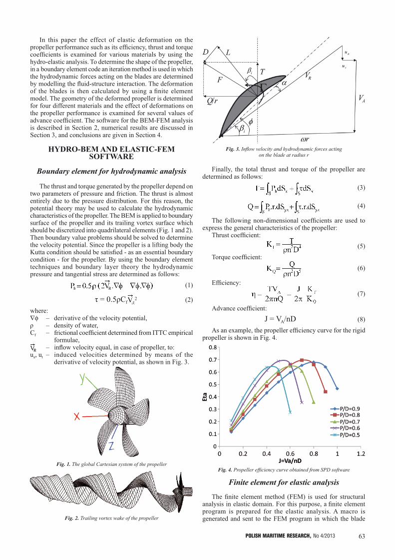
ua, ut – induced velocities determined by means of the derivative of velocity potential, as shown in Fig. 3.
Fig. 1. The global Cartesian system of the propeller
Fig. 2. Trailing vortex wake of the propeller
Fig. 3. Inflow velocity and hydrodynamic forces acting on the blade at radius r
Finally, the total thrust and torque of the propeller are determined as follows:
(3)
(4)
The following non-dimensional coefficients are used to express the general characteristics of the propeller:
Thrust coefficient:
(5)
Torque coefficient:
(6)
Efficiency:
(7)
Advance coefficient:
J = VA/nD (8)
As an example, the propeller efficiency curve for the rigid propeller is shown in Fig. 4.
Fig. 4. Propeller efficiency curve obtained from SPD software
Finite element for elastic analysis
The finite element method (FEM) is used for structural analysis in elastic domain. For this purpose, a finite element program is prepared for the elastic analysis. A macro is generated and sent to the FEM program in which the blade

64 POLISH MARITIME RESEARCH, No 4/2013
geometry is generated automatically by using the general characteristics of the propeller. And, the boundary conditions and loads are applied. The FEM model of propeller is then analyzed and the resulting data are sent to the output file.
In the generated macro the geometry model is formed according to the coordinates x, y, z of the points used in the BEM model. Therefore the results from the FEM can be simply transferred to the BEM software. The geometry model is meshed regularly with the 3D solid element of 20 nodes. It is clear that the loading conditions of blades depend on their position. In every revolution the maximum load is applied to each blade once. In the vertical and downward position the critical load is applied to each blade. In this situation the gravity and centrifugal forces act in the same direction. In addition the summation of the atmospheric pressure (P0), hydrostatic pressure (due to head of water above the hub axis) and hydrodynamic pressure (Ph) are applied onto the surface blade. Hydrodynamic pressure values are calculated by using the BEM program and sent to the FEM. The total pressure is determined for each element as follows:
P = Ph + P0 +ρ.g.(YCE + H) (9)
where:H – depth of the hub axis below the free surface, YCE – position of element centre in y - direction.
It should be noted that for the horizontal shaft the Coriolis effect is eliminated because the linear velocity and rotary velocity vectors are parallel to each other.
The procedure of the proposed methodThe algorithm of the proposed method is shown in Fig. 5.
First, the undeformed blade is analyzed in the HYDRO-BEM software in which the fluid-structure interaction is considered to determine the hydrodynamic forces, efficiency, KT1 and KQ1 coefficients. The deformations of the blade are then determined by using the ELASTIC-FEM software. In the second step, the hydrodynamic forces, efficiency, KT2 and KQ2 coefficients are determined based on the deformed shape of blade obtained from the BEM software. The deformations of the blade are calculated in the FEM software again based on new calculated hydrodynamic forces. By comparing the results from the two steps the convergence of values of the selected parameters (i.e. the maximum deflection, efficiency, KT and KQ), is checked. The procedure continues until convergence of values of the selected parameters is obtained. In the final step the deformed shape of blade and other parameters are calculated.
NUMERICAL RESULTS In this study a five-blade propeller is selected to examine the
effect of deformations on the propeller performance. The main dimensions of the propeller and the blade profile data are given in Tab. 1 and 2, respectively. The analysis is performed for four different materials: 13 % Chromium stainless steel, copper-nickel-aluminium alloys, high tensile- copper- brass and a polymer. The propeller material properties are listed in Tab. 3.
Tab. 1. Main dimensions of the propeller
Number of blades 5Diameter [m] 0.35
Hub ratio (rh/R) 0.2Expanded Area Ratio (EAR) 0.65
Skew angle [deg.] 15Rake angle [deg.] 10
Tab. 2. Maximum thickness, chord and pitch ratios of the propeller
r/R Thickness ratio (t/D)
Chord ratio (c/D)
Pitch ratio (P/D)
0.2 0.041 0.3183 0.53120.25 0.0385 0.3478 0.55280.30 0.036 0.375 0.57560.35 0.0334 0.3998 0.59810.40 0.0309 0.4218 0.61940.45 0.0284 0.4409 0.6380.50 0.0258 0.457 0.65190.55 0.0233 0.4695 0.66080.60 0.0208 0.4774 0.66680.65 0.0182 0.4786 0.67110.70 0.0157 0.4702 0.67370.75 0.0132 0.451 0.67310.80 0.0106 0.4197 0.66770.85 0.0081 0.3622 0.65730.90 0.0056 0.2513 0.64060.95 0.0044 0.2412 0.63011.00 0.003 0.0238 0.6059
Tab. 3. Material properties of the propellers
Material E(Gpa)
Poison coeff. (ν)
Specific gravity (ton/m3)
Tensile strength (Mpa)
13% Chromium Stainless
steel
196.133 0.3 7.7 690
Copper-nickel-
aluminium alloys
122.58 0.33 8.25 640
Copper high-
tensile brass102.97 0.35 7.6 540
Polymer material 3.19 0.39 1.15 95
In the analysis, for the sake of simplicity and time saving, only one blade of the propeller is modelled. The forces acting onto the propeller include the hydrodynamic loads (thrust and torque), centrifugal and gravity forces. The maximum force acts on the blade in the vertical and downward position because the centrifugal and gravity forces are in the same direction. The blade is deformed mostly due to the thrust and torque and the centrifugal force may be of special importance for high-rotating-speed. It is noted that skew and rake of propeller lead to an additional bending moment exerted to the blade.
Based on the flow chart presented in Fig. 5, the three-dimensional propeller and loads acting on the un-deformed blade are calculated by means of the HYDRO-BEM software and then sent to the ELASTIC-FEM software. The geometry model of the blade is shown in Fig. 6 (a) and (b). Because of the complicity of the blade shape the blade geometry is

65POLISH MARITIME RESEARCH, No 4/2013
Fig. 5. Flow chart of the proposed computational method
Fig. 6. The mesh generated on the blade surface (a, b), and the finite element mesh of the blade (c, d)
divided into several volumes. This helps to create an accurate model of the blade geometry. Fig. 6 (c) and (b) show the finite element model of the blade. To achieve a grid independent on the model, several FEM models with different element size are formed. The size of elements is then reduced step by step until the results converge appropriately.
The root of blade is assumed fixed. The hydrodynamic pressure is calculated by using the boundary element software. The elastic analysis of the blade is then performed by the finite element software to calculate deformation of the blade. This procedure is repeated until values of the maximum deformation, efficiency, thrust coefficient and torque coefficient converge.

66 POLISH MARITIME RESEARCH, No 4/2013
Fig. 7 shows the convergence of the values of these parameters for the polymer blade at J = 0.3. The variations of the parameters vanish after 10 steps of hydro-elastic analysis. The hydro-elastic analysis of each blade is performed for the five values of advance coefficient: J = 0.3, 0.4, 0.5, 0.6 and 0.7. Fig. 8 shows the pressure distribution on the face and back side of the undeformed and deformed polymer propeller. Fig. 9 shows the total pressure vector on the surface of steel blade at J = 0.3
Fig. 8. The hydrodynamic pressure distribution on polymer blade: a) undeformed back side, b) undeformed face side,
c) deformed back side, d) deformed face side
Fig. 9. Pressure applied to the blade surface at J = 0.3
The undeformed and deformed shape of polymer blade for J = 0.3 is shown in Fig. 10. The maximum principal stress of the copper–brass blade at J = 0.3 is shown in Fig. 11. The principal stress is negative on the back side of the blade except near the trailing and leading edges. The maximum tensile stress occurs in the middle of blade root at the face side. The similar stress field can be achieved from the hydro-elastic analysis of the blade for other values of J, however the maximum stress decreases with the increasing of advance coefficient values. The deformation field of the copper-brass blade is shown in Fig. 12. The deformation increases toward the blade tip due to increase of centrifugal force, hydrodynamic pressure and cantilever-mode behaviour of the blade.
The maximum deflection of the blade versus the advance coefficient (J) is shown in Fig. 13 for three different metal materials. Because the maximum deflection of the polymer blade is much greater, it is separately shown in Fig. 14. The thrust coefficient versus the advance coefficient J for deformed and undeformed propeller, is shown in Fig. 15. It is found
Fig. 7. Calculation convergence steps of the KT, KQ, efficiency and maximum deflection for polymer (nylon) blade at J = 0.3

67POLISH MARITIME RESEARCH, No 4/2013
that the thrust coefficient decreases with the increasing of advance coefficient, J. Except the polymer propeller, the thrust coefficient of the deformed blade is greater than that of the undeformed blade for all advance coefficient values. However, the thrust coefficient of the polymer blade is greater than that of the undeformed blade for J < 0.52 and smaller than that for J > 0.52. Moreover, the changes of this parameter for the polymer blade are greater than for other blades. Fig. 16 shows the torque coefficient versus the advance coefficient, J for deformed and undeformed propellers. The torque coefficient variations are similar to those of the thrust coefficient. The propeller efficiency versus the advance coefficient J is shown in Fig. 17. The maximum efficiency of undeformed blade occurs at J = 0.52. For J < 0.4, the efficiency of the deformed metal propellers is equal to that of the undeformed one, but for J > 0.4 the efficiency of the deformed propeller is higher than that for the undeformed one. The efficiency of the deformed polymer (blade) propeller is higher than that of the undeformed one for J < 0.52. However, for J > 0.52 the efficiency of the deformed polymer propeller is less than that of the undeformed one.
Fig. 12. Deformation of the copper brass blade at J = 0.3, a) at the face side, b) at the back side
Fig. 10. Deformed and undeformed shape of the polymer blade at J = 0.3
Fig. 11. Maximum principal stress of the cooper brass blade at J = 0.3, a) at the face side, b) at the back side

68 POLISH MARITIME RESEARCH, No 4/2013
Fig. 13. Maximum deflection versus advance coefficient for the used metal materials
Fig. 14. Maximum deflection versus advance coefficient for the used polymer material
The relative variations of propeller characteristics, related to un-deformed blade, are calculated as follows:
(10)
where index of “0” stands for undeformed blade.
Fig. 18, 19 and 20 show the curves of ΔKTr, ΔKQr and Δηr versus J, respectively. It is found that the effect of deformation on ΔKQr is lower than that on ΔKTr and ∆ηr. The parameters increase along with J increasing for the metal propellers, but the trend is opposite for the polymer propeller.
In order to show the effect of material, the ratio of elastic modulus and specific density (E/ρ) is calculated for four materials. The variation of ΔKTr and Δηr at various advance coefficient values are listed in Tab. 4 and 5, respectively. It is found that ΔKTr and Δηr decrease along with E/ρ increasing for J < 0.5, and increase for J > 0.5.
Fig. 15. The thrust coefficient KT versus advance coefficient (J) for the used materials
Fig. 16. The torque coefficient KQ versus advance coefficient (J) for the used materials

69POLISH MARITIME RESEARCH, No 4/2013
Fig. 20. Variations of efficiency, ∆ηr, versus advance coefficient J for the used materials
Tab. 4. Thrust coefficient (ΔKTr) for the propellers of four considered materials at various advance coefficient values
E/ρ J = 0.3 J = 0.4 J = 0.5 J = 0.6 J = 0.7
25.47182 1.303891 1.834449665 2.4950364 3.607889781 6.54376013
14.85818 1.396738 1.839448166 2.455327598 3.479036574 6.320907618
13.54868 1.44518 1.864440668 2.468563865 3.459213004 6.26012966
2.773913 5.288229 3.628911327 0.893448048 -4.529685796 -21.06969206
Tab. 5. Efficiency (∆ηr) for the propellers of four considered materials at various advance coefficient values
E/ρ J = 0.3 J = 0.4 J = 0.5 J = 0.6 J = 0.7
25.47182 0.357814579 0.476402328 0.743512891 1.370250741 3.571272838
14.85818 0.362401945 0.513476439 0.751792545 1.315307516 3.388130641
13.54868 0.392219827 0.5301598 0.7666959 1.2936632 3.327083242
2.773913 4.564429561 2.819486153 0.283164152 -4.26059738 -19.0446082
Fig. 17. Efficiency versus advance coefficient (J) for the used materials
Fig. 18. ΔKT (KT variations) versus advance coefficient J for the used materials
Fig. 19. ΔKQ (KQ variations) versus advance coefficient J for the used materials
CONCLUSIONS
A fluid-structure interaction in case of flexible marine propellers made of various materials have been analyzed by using the combined (BEM-FEM) software. The hydrodynamic load was determined by using the BEM and the structural

70 POLISH MARITIME RESEARCH, No 4/2013
response was analyzed by using the FEM. The deformation of propeller affects its hydrodynamic characteristics. In this paper, by considering the hydrodynamic and mechanical forces, the flexible propeller performance is examined. For performing the hydro-elastic analysis of the propeller a combined BEM - FEM method is proposed in which an iteration approach is used to predict the deformed shape of propeller. The hydrodynamic force is calculated by modelling solid-fluid interaction in the BEM software. The deformation of the propeller is then determined by using the finite element software (FEM). Three metal propellers and one propeller made of polymer material are analyzed by using the proposed method. From the performed analyses the following conclusions can be derived:
- The deformation of propeller has a lower effect on its torque coefficient (KQ) and a greater effect on its efficiency.
- It seems that the value of the advance coefficient J at which the maximum efficiency occurs has an important impact on the variation of characteristics of the deformed propeller. In the case study, the maximum efficiency occurs at J = 0.5, and ΔKTr and ∆ηr decreases with the increasing of E/ρ ratio for J < 0.5 and increases for J > 0.5.
BIBLIOGRAPHY
1. Sontvedt, T.: Propeller blade stress application of finite element methods. Computers & Structures, Vol. 4, pp. 193-204, 1974.
2. Young, Y.L.: Hydro-elastic behaviour of the flexible composite propeller in wake inflow. 16th conf. on composite materials, Kyoto, Japan, 2007.
3. Young, Y.L.: Fluid-structure interaction analysis of flexible composite marine propellers. Journal of Fluids and Structures, Vol. 24, 799–818, 2008.
4. Blasques, J. P., Berggreen C., Poul Andersen, P.: Hydro-elastic analysis and optimization of a composite marine propeller. Marine structure, Vol. 23, 2010.
5. Lin H. J., Lai W. M., Kuo, Y. M.: Effect of stacking sequence on nonlinear hydro-elastic behaviour of composite propeller. Journal of Mechanics, Vol. 26, No. 3, September 2010.
6. Mulcahy, N. L. and Prusty B. G. and Gardiner C. P.: Hydro-elastic tailoring of flexible composite propellers. Ships and Offshore Structures, Vol. 5, No. 4, 359–370, 2010.
7. Chau, T. B.: 2-D versus 3-D stress analysis of a marine propeller blade. Zeszyty Naukowe Akademii Morskiej w Gdyni, No. 64, July 2010.
8. Koronowicz, T., Krzemianowski, Z., Tuszkowska, T., Szantyr, J.A.: A complete design of ship propellers using the new computer system. Polish Maritime Research, Vol. 16, No. 1 (59); pp.29-34, 2009.
9. Ghassemi, H., Ghadimi, P.,: Computational hydrodynamic analysis of the propeller-rudder and the AZIPOD systems. Ocean Engineering, Vol. 34, pp.117-130, 2007.
10. Ghassemi, H.: The Effect of Wake Flow and Skew Angle on the Ship Propeller Performance. Scientia Iranica, Vol. 16, No. 2, pp.149-158, 2009.
11. Ghassemi, H.: Hydrodynamic performance of coaxial contra-rotating propeller (CCRP) for large ships. Polish Maritime Research, Vol. 16, No. 1 (59), pp.22-28, 2009.
12. Ghassemi, H.: Hydrodynamic characteristics of the surface-piercing propellers for the planing craft. J. Marine Sci. Appl., Vol. 7, pp.147-156, 2008.
CONTACT WITH THE AUTHORS
Hassan Ghassemi, Prof.,Department of Ocean Engineering,
Amirkabir University of Technology, Tehran, IRAN e-mail: [email protected],
http://hmaa.itgo.com/ghassemi.html tel.: +98-21-64543112, fax: +98-21-66412495
Morteza Ghassabzadeh, Ph.D.,Marine Industry Research Centre,
Amirkabir University of Technology, Tehran, IRAN e-mail: [email protected]
Maryam Gh. Saryazdi, Ph.D.,Vehicle Technology Research Institute,
Amirkabir University of Technology, Tehran, IRANe-mail: [email protected]