EET 2261 Unit 13 Controlling Stepper Motors and Servos Read Almy, Chapter 21. Lab #13 due next...
21
EET 2261 Unit 13 Controlling Stepper Motors and Servos Read Almy, Chapter 21. Lab #13 due next week. Final Exam next week.
-
Upload
morris-hensley -
Category
Documents
-
view
218 -
download
0
Transcript of EET 2261 Unit 13 Controlling Stepper Motors and Servos Read Almy, Chapter 21. Lab #13 due next...

EET 2261 Unit 13 Controlling Stepper Motors and Servos
Read Almy, Chapter 21.
Lab #13 due next week.
Final Exam next week.

• There are many kinds of electric motors. (See Wikipedia article.)
• In many motors, the rotor spins continuously, with no way of precisely controlling the motor’s rotational position.
• Stepper motors and servos are two widely used kinds of motors whose position can be precisely controlled.
Stepper Motors and Servos

• Our textbook does not discuss stepper motors or servos (except in Question 7 on page 200).
• But Chapter 21 discusses pulse width modulation (PWM), which is the technique used to control servos.
Coverage of Motors in the Textbook

• A stepper motor is a digitally controlled motor that allows precise control over the position of the motor’s rotor.
• Changes in the digital input rotate the motor’s rotor by a precise amount, which is called a step or step angle.
• Depending on the motor, this step angle may be as small as 1 (or less) or as large as 45.• On our motors, the step angle is 3.6.
Stepper Motors

• Our motor is made by Howard Ind., part number 1-19-4202.
• As shown on its specifications sheet, it’s a unipolar motor with a 3.6 step angle.
Our Stepper Motor

• Several widely used motor driver ICs exist for interfacing motors to microcontrollers. • On our Dragon12 board, the TB6612FNG driver
serves this purpose (U12 near the board’s lower left corner).
Interfacing the Microcontroller to the Stepper Motor

• This chip contains a popular driver design called an H-bridge. It is often used to control DC motors and stepper motors.
• TB6612FNG datasheet.
Toshiba TB6612FNG

• On the Dragon12 board, the TB6612FNG is connected to Ports B and P of the HCS12.
• Figure from Dragon12 Schematic Diagram 5.
Connections to TB6612FNG

• Once you’ve made the proper connections and configured the HCS12’s ports, stepper motors are easy to program. The following code will turn our motor counterclockwise (CCW):
Code for Turning a Stepper Motor
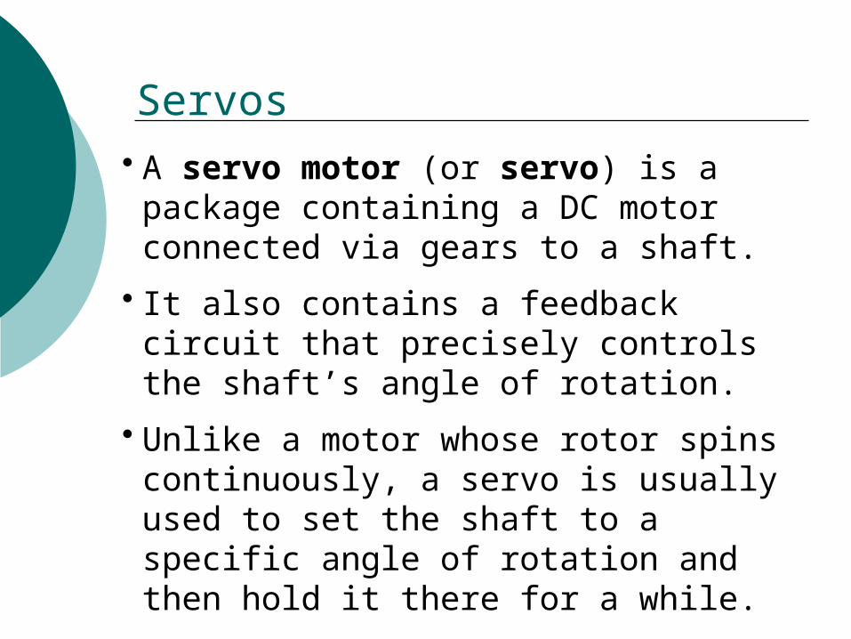
• A servo motor (or servo) is a package containing a DC motor connected via gears to a shaft.
• It also contains a feedback circuit that precisely controls the shaft’s angle of rotation.
• Unlike a motor whose rotor spins continuously, a servo is usually used to set the shaft to a specific angle of rotation and then hold it there for a while.
Servos

• Servos are commonly used in small robotics and in radio-controlled (RC) airplanes, cars, and boats.
• In an RC airplane, for example, servos may control the plane’s throttle, rudder, elevators, ailerons, landing gear, etc.
• Next slide shows inner workings of an RC airplane.
Servos in RC Vehicles

Servos and Stepper Motors

• Servos have three wires:• Power (red)• Ground (black)• Control signal (yellow or white)
Wiring a Servo

• The Dragon12 board has four connectors (near the center of the top edge) for servos, labeled PP4, PP5, PP6, PP7.
• Jumper J35 lets you choose whether to power the servo from the board or from an external supply. We’ll power it from the board, but to do so we must have the power adapter plugged in.
Connecting Servos to the Dragon12

• On the Dragon12 board, the servo outputs are connected to Port P of the HCS12.
• Figure from Dragon12 Schematic Diagram 5.
Dragon12 Connections

• Our servo is made by Hitec, part number HS-311.
• See ServoCity’s webpage for detailed specifications.
Our Servo

• The servo’s control signal is a 50 Hz pulse train. Therefore, what is this signal’s period?
• As shown on the next slide, the width of the pulse is crucial in controlling the servo.
Controlling a Servo
Period = ?

• The control signal’s pulse width determines the shaft’s angle of rotation.
• Typically this pulse width ranges from about 0.5 ms to about 2.5 ms, interpreted as follows:
• 1.5 ms pulse width: 0 rotation.
• Pulse width less than 1.5 ms: rotate counterclockwise (up to 90, for our servo).
• Pulse width greater than 1.5 ms: rotate clockwise (up to 90).
Controlling a Servo

• The term pulse width modulation (PWM) refers to the technique of varying a signal’s pulse width to control a device such as a servo. (PWM is used to control other kinds of devices, too, including DC motors.)
Pulse Width Modulation

• One way to perform PWM using the HCS12 would be to write a loop that sets an output pin HIGH and LOW at the right times to generate pulses of the desired width and frequency.
• This approach would tie up a lot of the CPU’s time.
• A more efficient way is to use the HCS12’s built-in PWM block. Using this approach, once we have configured the PWM block correctly, it will generate pulses of the desired width and frequency without tying up the CPU.
PWM Using the HCS12
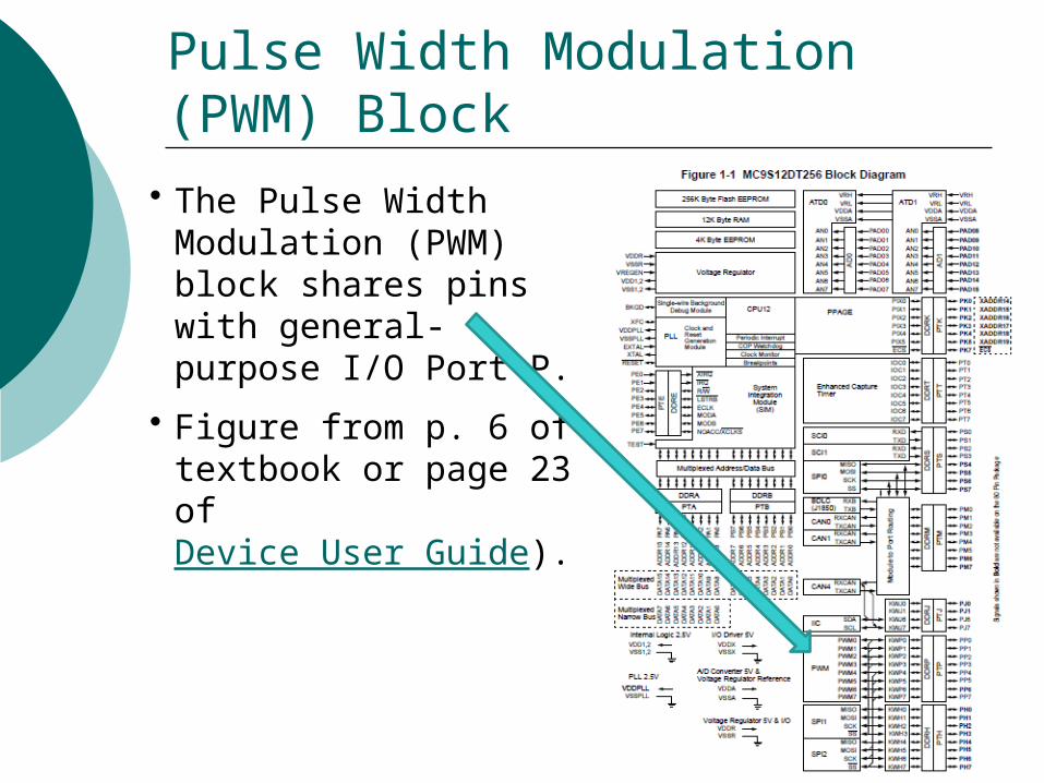
• The Pulse Width Modulation (PWM) block shares pins with general-purpose I/O Port P.
• Figure from p. 6 of textbook or page 23 of Device User Guide).
Pulse Width Modulation (PWM) Block