EEE2243 Digital System Design Chapter 5: Simple Design Case Studies by Muhazam Mustapha, February...
20
EEE2243 Digital System Design Chapter 5: Simple Design Case Studies by Muhazam Mustapha, February 2011
-
Upload
brent-roberts -
Category
Documents
-
view
217 -
download
0
Transcript of EEE2243 Digital System Design Chapter 5: Simple Design Case Studies by Muhazam Mustapha, February...

EEE2243Digital System Design
Chapter 5: Simple Design Case Studies
by Muhazam Mustapha, February 2011

Learning Outcome
• By the end of this chapter, students are expected to understand a few design case studies– Decoder– Multiplexer– Sequence Generator– Secure Car Key– Flight Attendant Call-Button

Chapter Content
• Decoder
• Multiplexer
• Sequence Generator
• Secure Car Key
• Flight Attendant Call-Button

Decoder

Decoder• A decoder is a combinational circuit that
activates its output according to the binary value of its input
• General block diagram of active high 3-bit decoder:
3-to-8 Decoder
I0
I1
I2
O0
O1
O2
O3
O4
O5
O6
O7
If I2I1I0 = 010, O2 will be set to HIGH, the rest will be LOW

Decoder• Most of the decoders available in the market are
inverted output (active low):
I0
I1
I2
O0
O1
O2
O3
O4
O5
O6
O7
If I2I1I0 = 010, O2 will be set to LOW, the rest will be HIGH
3-to-8 Decoder

Decoder• General truth table and circuit of 2-to-4 active
high decoder:
I1 I0 O0 O1 O2 O3
0 0 1 0 0 0
0 1 0 1 0 0
1 0 0 0 1 0
1 1 0 0 0 1

Decoder Verilog• From the
definition of decoder it might be obvious now that it easier to write its Verilog code in Boolean algebra rather than behavioral approach
module Decoder2to4(codein, codeout); input [1:0] codein; output [3:0] codeout; reg [3:0] codeout; parameter CO0 = 1; // code out 0 parameter CO1 = 2; parameter CO2 = 4; parameter CO3 = 8;
always@(codein) begin case (codein) 0: codeout = CO0; 1: codeout = CO1; 2: codeout = CO2; 3: codeout = CO3; endcase endendmodule

Multiplexer

Multiplexer• A multiplexer (mux) is a combinational circuit
that transfers its MULTI line inputs to a SINGLE line output according to the binary value of some selector lines
• General block diagram:
S0
I0
I1
I2
I3Output
I5
I6
I7
If S2S1S0 = 010, value at I2 will be sent to Output
8-to-1 Mux
I4
S1S2

Multiplexer• General truth table of 8-to-1 multiplexer:
S1 S0 Output
0 0 I0
0 1 I1
1 0 I2
1 1 I3
301201101001 ISSISSISSISSOutput

Multiplexer• Based on the previous truth table, multiplexer
can be built using decoder:S1 S0
I3
I2
I1
I0
Decoder
MultiplexerOutput

Multiplexer• The simplified circuit:
S1 S0
I3
I2
I1
I0
Output

Multiplexer Verilog• Multiplexer is
better be defined in behavioral approach
module Mux4to1(sel, lin, lout); input [3:0] lin; input [1:0] sel; output lout; reg [3:0] lout;
always@(sel) // latched, lin no effect begin case (sel) 0: lout = lin[0]; 1: lout = lin[1]; 2: lout = lin[2]; 3: lout = lin[3]; endcase endendmodule

Secure Car Key
Vahid Example 3.4 pg 127
Secure Car Key
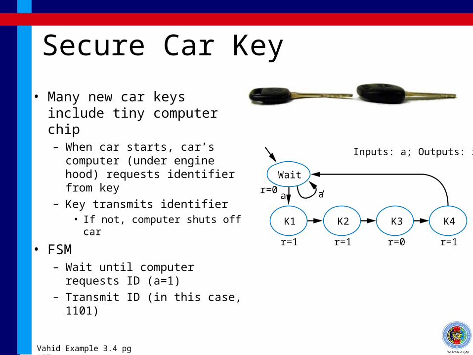
• Many new car keys include tiny computer chip– When car starts, car’s
computer (under engine hood) requests identifier from key
– Key transmits identifier• If not, computer shuts off car
• FSM– Wait until computer requests
ID (a=1)– Transmit ID (in this case,
1101)
K1 K2 K3 K4
r=1 r=1 r=0 r=1
Wait
r=0
Inputs: a; Outputs: r
a’a
Vahid Example 3.4 pg 127

Secure Car Key
• Nice feature of FSM– Can evaluate output
behavior for different input sequence
– Timing diagrams show states and output values for different input waveforms
K1 K2 K3 K4
r=1 r=1 r=0 r=1
Waitr=0
Inputs: a;Outputs: r
a’a
Wait Wait K1 K2 K3 K4 Wait Wait
clk
Inputs
Outputs
State
a
r
clk
Inputsa
K1Wait Wait K1 K2 K3 K4 Wait
Output
State
r
Q: Determine states and r value for given input waveform:
a
Vahid Example 3.4 pg 127

Flight Attendant Call-Button
Vahid Example 3.1 pg 118

Flight-Attendant Call Button• D flip-flop will store bit• Inputs are Call, Cancel, and present
value of D flip-flop, Q• Truth table shown below
Preserve value: if Q=0, make D=0; if Q=1, make D=1
Cancel -- make D=0
Call -- make D=1
Let’s give priority to Call -- make D=1
Circuit derived from truth table, using Chapter 2 combinational
logic design process
Call
button
Cancel
button
Flightattendantcall-button
system
Bluelight
D Q’
QClk
Callbutton
Cancelbutton
Bluelight
Call
Cancel
Q
Vahid Example 3.1 pg 118

Verilog Code• Write the Verilog code yourself for the cases of
Secure Car Key and Flight Attendant Call-Button