EEE2243 Digital System Design Chapter 6: RTL Design by Muhazam Mustapha, April 2012
Upload
christiana-penelope-frenchCategory
view
222download
1
EEC4113Data Communication &
Multimedia SystemChapter 1: Introduction
by Muhazam Mustapha, September 2012
Learning Outcome
• By the end of this chapter, students are expected to have some surface overview of models, networking, protocol architecture & standards related to data communication

Chapter Content
• Communications model
• Data communication networking
• Protocol architecture– OSI– TCP/IP
• Standards

Communications Model
CO1

Data Communication Tasks
• Communications model• Data communication
networking• Protocol architecture
– OSI– TCP/IP
• Standards
• Address• Routing• Recovery• Message formatting• Security• Network management
Fundamental purpose of communications system: Exchange of data between two parties
CO1
Data Communications Networking
CO1

Data Communication Networking
• Point to point communication not usually practical
• Devices are far apart
• Large set of devices would need impractical number of connections
• Solution is a communications network:– Wide Area Network (WAN)– Local Area Network (LAN)
CO1
Wide Area Network (WAN)
• Large geographical area
• Crossing public rights of way
• Rely in part on common carrier circuits
• Used technologies– Circuit switching– Packet switching– Frame relay– Asynchronous Transfer Mode (ATM)
CO1
WAN Technologies• Circuit Switching
– Dedicated communications path established for the duration of the conversation
• e.g. telephone network
• Packet switching– Data sent out of sequence– Small chunks (packets) of data at a time– Packets passed from node to node between
source and destination– Used for terminal-to-computer and computer-
to-computer communicationsCO1

WAN Technologies• Frame Relay
– Packet switching systems have large overheads to compensate errors
– Modern systems are more reliable– Errors can be caught in end system– Most overhead for error control is stripped out
• Asynchronous Transfer Mode (ATM)– Evolution of frame relay– Little overhead for error control– Fixed packet (called cell) length– Anything from 10Mbps to Gbps– Constant data rate using packet switching techniqueCO1

Local Area Network (LAN)
• Smaller scope– Single or a cluster of building
• Usually owned by same organization
• Data rates much higher than WAN
CO1

LAN Configurations
• Switched– Switched Ethernet
• May be single or multiple switches
– ATM LAN– Fiber Channel
• Wireless– Mobility– Ease of installation
CO1

Metropolitan Area Networks (MAN)
• Middle ground between LAN and WAN
• High speed
• Cover larger area than LAN– City– Town
• Private or public network
CO1

Networking Configuration
Client
Service Provider
Phone line, DSL Internet
Client
Client
ATM Network
LAN
Ethernet switches
Local Servers
CO1
Standardized Protocol Architecture for
Data Communications
CO1

Standardized Protocol Architecture• Required for devices to communicate• Vendors have more marketable products• Customers can insist on standards based equipment• Two standards
– OSI Reference model– TCP/IP protocol suite
• Also:– Internetwork Packet eXchange/Sequenced Packet eXchange
(IPX/SPX)– NetBIOS Enhanced User Interface (NetBEUI)– AppleTalk– IBM Systems Network Architecture (SNA)
CO1

OSI
CO1
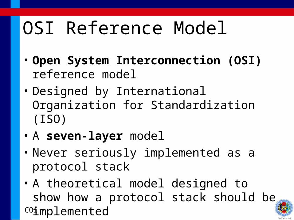
OSI Reference Model
• Open System Interconnection (OSI) reference model
• Designed by International Organization for Standardization (ISO)
• A seven-layer model
• Never seriously implemented as a protocol stack
• A theoretical model designed to show how a protocol stack should be implemented
CO1

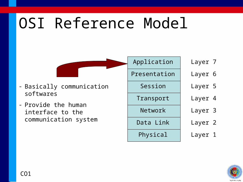
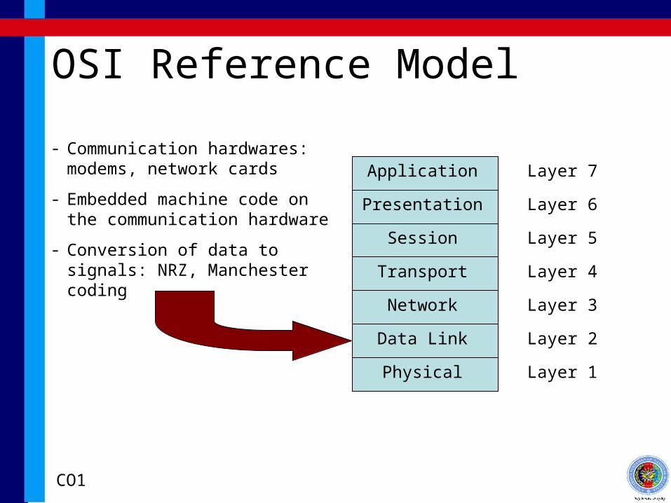
OSI Reference Model
Application Layer 7
Presentation Layer 6
Session Layer 5
Transport Layer 4
Network Layer 3
Data Link Layer 2
Physical Layer 1
CO1
OSI Reference Model
Application Layer 7
Presentation Layer 6
Session Layer 5
Transport Layer 4
Network Layer 3
Data Link Layer 2
Physical Layer 1
- Basically communication softwares
- Provide the human interface to the communication system
CO1

OSI Reference Model
Application Layer 7
Presentation Layer 6
Session Layer 5
Transport Layer 4
Network Layer 3
Data Link Layer 2
Physical Layer 1
- Standardizes data representation
- Decouples application from data
CO1
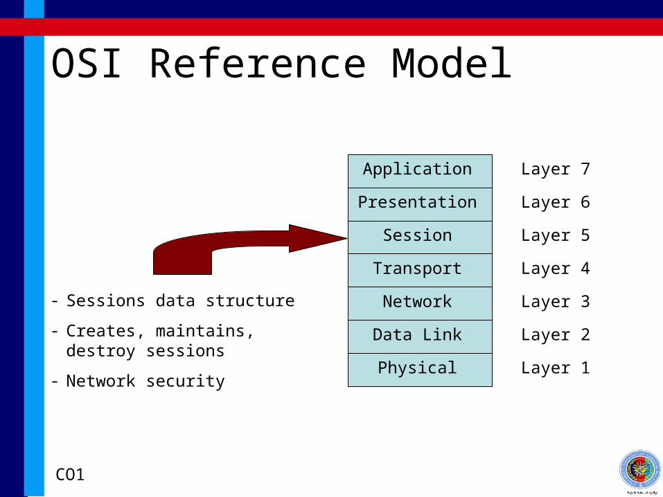
OSI Reference Model
Application Layer 7
Presentation Layer 6
Session Layer 5
Transport Layer 4
Network Layer 3
Data Link Layer 2
Physical Layer 1
- Sessions data structure
- Creates, maintains, destroy sessions
- Network security
CO1

OSI Reference Model
Application Layer 7
Presentation Layer 6
Session Layer 5
Transport Layer 4
Network Layer 3
Data Link Layer 2
Physical Layer 1
- Low Level Communication APIs
- Creates, maintains, destroy connection to network devices
- Routing technology
CO1

OSI Reference Model
Application Layer 7
Presentation Layer 6
Session Layer 5
Transport Layer 4
Network Layer 3
Data Link Layer 2
Physical Layer 1
- Bit level manipulation
- Communication hardware device driver
- Error detection, recovery, transparent flow
CO1
OSI Reference Model
Application Layer 7
Presentation Layer 6
Session Layer 5
Transport Layer 4
Network Layer 3
Data Link Layer 2
Physical Layer 1
- Communication hardwares: modems, network cards
- Embedded machine code on the communication hardware
- Conversion of data to signals: NRZ, Manchester coding
CO1

OSI Reference Model
Application Layer 7
Presentation Layer 6
Session Layer 5
Transport Layer 4
Network Layer 3
Data Link Layer 2
Physical Layer 1
- Actual connectors
- Cables, optical fibers, telephone line
CO1

OSI Environment
Application
Presentation
Session
Transport
Network
Data Link
Physical
Application
Presentation
Session
Transport
Network
Data Link
Physical
Headers being attached at each layer
Headers being stripped off at each layer
Data
Connectors, switchers
Data
CO1
TCP/IP
CO1
TCP/IP Model
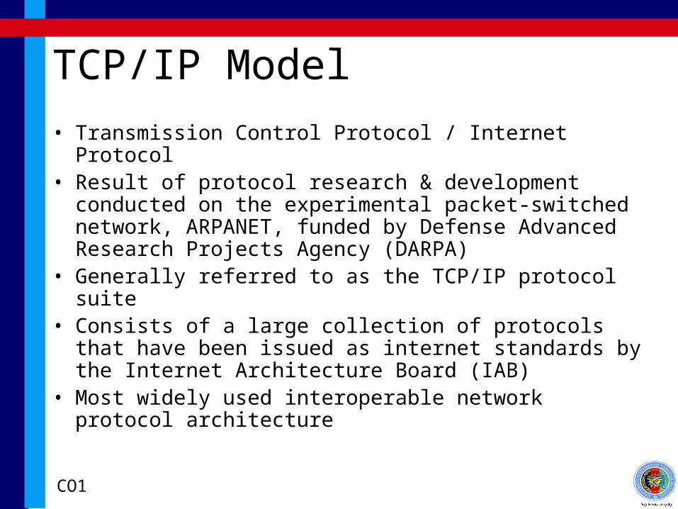
• Transmission Control Protocol / Internet Protocol• Result of protocol research & development conducted on
the experimental packet-switched network, ARPANET, funded by Defense Advanced Research Projects Agency (DARPA)
• Generally referred to as the TCP/IP protocol suite• Consists of a large collection of protocols that have been
issued as internet standards by the Internet Architecture Board (IAB)
• Most widely used interoperable network protocol architecture
CO1
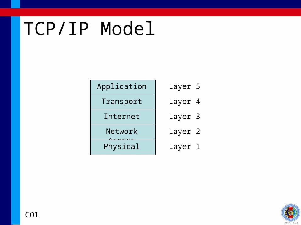
TCP/IP Model
Application Layer 5
Transport Layer 4
Internet Layer 3
Network Access Layer 2
Physical Layer 1
CO1

OSI vs TCP/IP
Application
Presentation
Session
Transport
Network
Data Link
Physical
Application
Transport
Network Access
Internet
Physical
Communication Softwares &
Device Drivers
Communication Hardwares &
Embedded Code
Connectors
CO1

TCP/IP Layers
Application
Transport
Internet
Network Access
Physical
- Communicating softwares
- Make use of many protocols available: FTP, HTTP, SMTP, POP, etc
- Control data (standardized), data structure, and sessions
CO1

TCP/IP Layers
Application
Transport
Internet
Network Access
Physical
- Low Level Communication APIs
- Creates, maintains, destroy connection to network devices
- Application transparent communication
- Device driver
CO1

TCP/IP Layers
Application
Transport
Internet
Network Access
Physical
- Routing functions at communication hardware
- Internet Protocol and IP address
CO1

TCP/IP Layers
Application
Transport
Internet
Network Access
Physical
- Embedded Code on Communication hardwares: modems, network cards
- Conversion of data to signals: NRZ, Manchester coding
- Bit level manipulation
- Error detection, recovery, transparent flow
CO1

TCP/IP Layers
Application
Transport
Internet
Network Access
Physical
- Actual connectors
- Cables, optical fibers, telephone line
CO1

Operations of TCP/IP
• For successful communication, two levels of addressing are needed
• Each host on a subnetwork must have a unique global internet address: IP address
• Each process with a host must have an address that is unique within the host to allow TCP to deliver data to proper process: ports
CO1
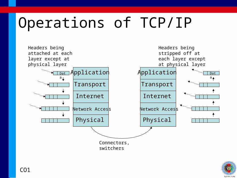
Operations of TCP/IP
Application
Transport
Network Access
Internet
Physical
Application
Transport
Internet
Physical
Headers being attached at each layer except at physical layer
Headers being stripped off at each layer except at physical layer
Connectors, switchers
Network Access
Data Data
CO1