EE Electromechanical Level Measuring System B0-0905
10
Electromechanical Level Measuring System
Transcript of EE Electromechanical Level Measuring System B0-0905

Electromechanical Level Measuring System

1
1
1
1
1
1
1
1
1
1 Four
1
1
1
1
1
1
Measurement immunes from the interference of
environment such as sound waves, dust,
capacitance, or temperature change.
User-friendly in touch buttons with
microprocessor-based calculation design.
High level and low level alarm.
LCD Dot matrix: 8 x 2.
Analog output: 4-20mA dc.
Pulse output:
Transistor output NPN/PNP
Relay output 3A/250Vac
Cable Break Alarm: System will detect cable
broken during measuring.
Plumb Buried Alarm: System will detect plumb
buried by the medium.
Start Modes: auto start, manual start,
intelligent start, and external triggered start.
Intelligent Start: Measuring interval is inverse
proportional to medium level.
Auto Return Setup: Prevent sensing weight from
buried or sliding into the tank pivot and avoid
damage facility equipment while tank is empty.
Material Fill-Up Protection: Reduce the possibility
of plumb being buried.
Measuring range of 30m (Standard), max. up to
40 m.
RS485 MODBUS communication protocol.
Various selections of .
(10mm/pulse)
(100mm/pulse)
FiFineTek's Electro-Mechanical Level Measuring
System (EE300 series) consists of plumb
measure the material level. It
senses the weight status and count the cable wire
length from the device to the level of material.
The EE series equips with robust position sensor
to calculate the rotation of pulley which can be
operated in harsh environment. Moreover, it can
connects with FineTek's material measurement
system (MMS) to build an interactive control
system, save the operator patrolling time and
maintenance.
, cable
wire, measuring pulley, position sensor, and
control board to
APPLICATION
1
1
Widely utilized in mining, cement, chemical,
and feed industries.
Suitable for applications of dusty silo, pellet silo,
solids silo, liquid silo, unsealed, or vacuum
sealed silo.
FEATURESWORKING PRINCIPLE
PRODUCT INTRODUCTION
Rear View: Wiring Mechanism
Measuring Pulley
AL Housing
Receiving Pulley
AL Base
Protection Rating: IP66(IEC60947-2)
IEC Standards for Voltage: IEC60947-2
IEC Standards for Isolation: IEC60092-504
IEC Standards for changes in power supply:
IEC60092-504
IEC Standards for power supply failure:
IEC60092-504
1
1
1
1
1
Product Testing Standards

2
SPECIFICATION
Category
Power Supply
Transistor Measuring Resolution
Relay Output Measuring Resolution
Measuring Speed
Analog Output
Pulse Output
Display
Status LED
Operating Temperature
Measuring Range
Protection Level
Relay Output
Ambient Temperature
Anti-Dew Heater
Cable Break Detection
Manual/Auto Measuring Mode
Motor Protection
Malfunction Diagnosis Display
Material Fill-Up Protection
Communication Protocol( )RS485
Intelligent Start
Reset Output
Cable Wire
No .
1
2
3
4
5
6
7
8
9
10
11
12
13
14
15
16
17
18
19
20
21
22
23
24
( )LCD Dot matrix , 8 X 2
Specification
100~240VacK10%, 50/60 Hz
K3pulse(version with10mm/pulse)
K1pulse(version with100mm/pulse)
0.23m/s
0/4-20mA K1%
1. NPN / PNP (
2. Relay 3A/250Vac (
10mm/pulse)System sends pulse output every 1cm. Each pulse has interval of 10ms.
100mm/pulse)System sends pulse output every 10cm. Each pulse has interval of 15ms.
1.Lock (Fill-Up Protection)
2.RUN
3.Buried
4.Break
5.Auto
6.High Alarm
7.Low Alarm
-35BC- 80BC
30m Max
IP66
-35BC- 60BC
SPDT 3A/250Vac X 3
1. HI Alarm
2. LO Alarm
3. Buried: Blink for 1 second when alarm triggers
Break : Blink for 2 seconds when alarm triggers
Lock : LED on when alarm triggers
Yes
Yes
( )Yes 0.1-99h
Yes
Yes
Yes
Yes
Frame
Baudrate
( )Reset 3A/250Vacf1.2mm
C8N1.C8N2.C801.C8E1.C7N2.C701.
C7E1.C702. C7E2.
1200.2400.4800.9600. 11520.
14400.19200.28800.57600
Measuring interval is inverse proportional to medium level.
(Red) On
(Yellow) On
(Red) Blink for 1 second
(Red) Blink for 2 seconds
(Blue) On
(Red) On
(Red) On
Start heating <16BC ( prevent frostbite, prevent dew ) in 100 W
optional
Sensing Weight Buried Detection

3
Front View: Electric Board & Motor
Front View Side View Top View
Rear View: Wiring Mechanism
Switching Power Supply
Measuring Pulley
AL Housing
Receiving Pulley
AL Base
Control Board
Conduit
Heater
M25HP1.5
Motor
SKETCH & DRAWING/ DIMENSION
Sketch & Drawing
Dimension
Dust Brush
Dust Wiper
1/4" PT Air Intake HoleM4 Outer Case Ground
M4 Ground
190
325
100
265
325
180
100
(400)
4-f19
P.C.D.f160
180
90B90B
45B45B
18.8B
180
4
13
14
15
16
12
11
10
8
7
6
5
4
3
9
2
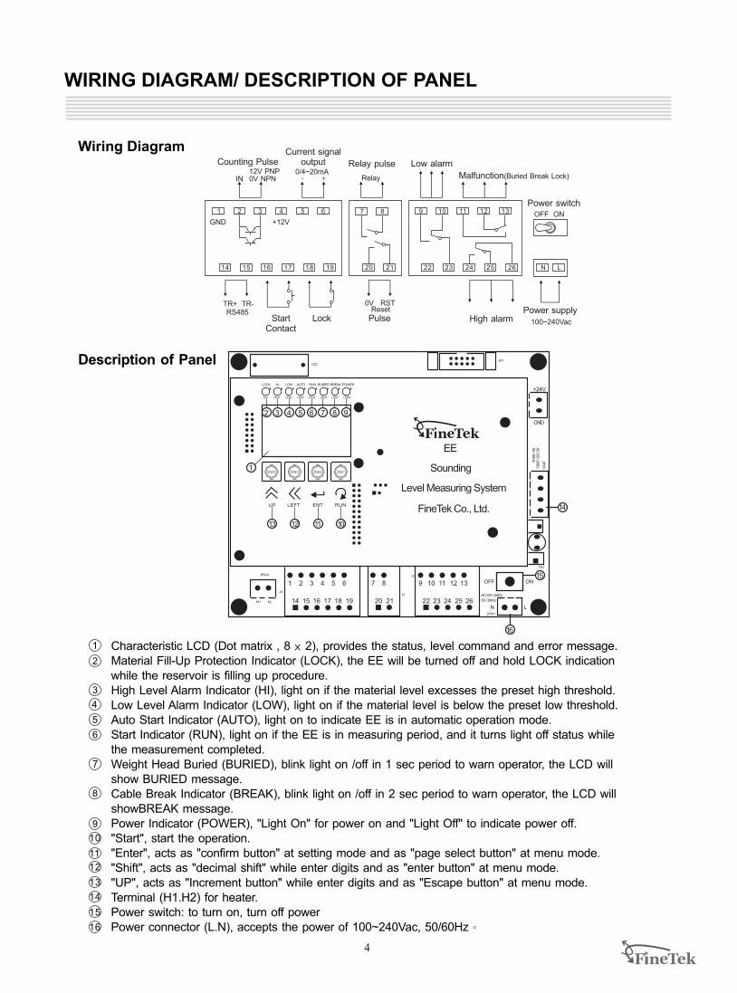
1 Characteristic LCD (Dot matrix , 8 × 2), provides the status, level command and error message.Material Fill-Up Protection Indicator (LOCK), the EE will be turned off and hold LOCK indication while the reservoir is filling up procedure.High Level Alarm Indicator (HI), light on if the material level excesses the preset high threshold.Low Level Alarm Indicator (LOW), light on if the material level is below the preset low threshold.Auto Start Indicator (AUTO), light on to indicate EE is in automatic operation mode.Start Indicator (RUN), light on if the EE is in measuring period, and it turns light off status while the measurement completed.Weight Head Buried (BURIED), blink light on /off in 1 sec period to warn operator, the LCD will show BURIED message.Cable Break Indicator (BREAK), blink light on /off in 2 sec period to warn operator, the LCD will showBREAK message.Power Indicator (POWER), "Light On" for power on and "Light Off" to indicate power off."Start", start the operation."Enter", acts as "confirm button" at setting mode and as "page select button" at menu mode."Shift", acts as "decimal shift" while enter digits and as "enter button" at menu mode."UP", acts as "Increment button" while enter digits and as "Escape button" at menu mode.Terminal (H1.H2) for heater.Power switch: to turn on, turn off powerPower connector (L.N), accepts the power of 100~240Vac, 50/60Hz。
WIRING DIAGRAM/ DESCRIPTION OF PANEL
LOCK HI LOW AUTO RUN BURIED BREAK POWER
RC1 LED1 LED2 LED3 LED4 LED5 LED6LED7
C23JP1
+24V
GND
JPW
3
AC
100~240V
50
/ 60H
z
TN1
JPW1
LN
AC100~240V
50 / 60Hz
J2
J3
9 10 11 12 13
22 23 24 25 26
7 8
20 21
1 2 3 4 5 6
14 15 16 17 18 19
J4
JPW4
M+ M-
UP LEFT ENT RUN
SW4 SW3 SW2 SW1
EE
Sounding
Level Measuring System
FineTek Co., Ltd.
1
2 3 4 5 6 7 8 9
13 12 11 10
16
15
14
OFF ON
IN12V PNP0V NPN
0/4~20mARelay
OFF ON
TR+ TR-RS485
0V RSTReset
100~240Vac
1 2 3 4 5 6
14 15 16 17 18 19 20 21
7 8 9 10 11 12 13
22 23 24 25 26 N L
Counting PulseCurrent signal
output Relay pulse Low alarm
Malfunction(Buried Break Lock)
Power switch
Power supplyHigh alarmPulseLockStart
Contact
+12VGND
Wiring Diagram
Description of Panel

PROGRAM MING GUIDE
5
0/4-20mA4-20mA
ADD/DECADD
A/H/SAUTO
Timer01.0
Smart01.0
H30.00
HI Alarm05.00
LO Alarm20.00
FormatRTU
ID001
Baudrate9600
FrameC8N1
0/4-20mA4-20mA
0-20mA
ADD/DECADD
DEC
A/H/S
AUTO
Manual
Smart
(A)Timer, (H)Manual, (S)SmartSwitch Mode.
UP
Timer 00.1-99.9h
Timer Setup to change set value.
UP LEFT
Smart 00.1-99.9h
Smart Timer to change set value.
UP LEFT
H(silo height) 30.00m
Tank Height to change set value.2.00~30.00m.
UP LEFT
HI Alarm 5.00m
High Alarm Setup change set value.
to UP LEFT
LO Alarm 20.00m
Low Alarm Set Value change set value.
to UP LEFT
FormatRTU
ASC
ID 001
ID setup to change set value.
UP LEFT
BaudRate
1200240048009600
1152014400192002880057600
BaudRate Setup select 9 modes.
to
Frame
C8N1C8N2C8O1C8E1C7N2C7O1C7E1C7O2C7E2
Frame Setup modes.
to select 10 UP
F/G Switch Mode.UP
Analog Output Switch Mode.UP
Communication Switch Mode.UP
Level 0.00m Start
RUN
LEFT
ENT
LEFT
ENT
LEFT
ENT
LEFT
ENT
LEFT
ENT
LEFT
ENT
LEFT
ENT
LEFT
ENT
LEFT
ENT
LEFT
ENT
LEFT
ENT
LEFT
ENT
UP
ENT
UP
UP
UP
UP
UP
UP
UP
UP
UP
UP
UP
ENT
ENT
ENT
ENT
ENT
ENT
ENT
ENT
ENT
ENT
ENT
Air Zone00.00 Air Zone 00.00
Zero distance to change set value.Setting for blind area of tank .
UP LEFT
LEFT
ENT
UP
ENT
Select RTU or ASCII.
Select the 0-20mA~4-20mA.
Select the Addition or decrease.
Select Auto Start or Manual or Smart.
0.1h(6m)~99.9h(99h54m).
0.1h(6m)~99.9h(99h54m).
UP LEFT
1: Measuring Length
2: Analog Output
3: Calculation in Addition / Subtraction For Level Position
4: Operation mode selection
5: Time period for measuring at auto mode
6: Start Time for measuring at SMART mode
7: The high threshold for reservoir
8: The zero reference for reservoir
9: High alarm
10: Low Alarm
11: Communication format
12: Communication ID
13: Communication baud rate
14: Communication frame

6
Caution
EE300. Be sure the and reservoir is in normal and avoid from the sensing weight head has the possiblity of being stuck by conveyer or stirred by any mechanism near inlet or outlet. Before setting, user should note that the measuring level should not excess the bottom of reservoir or storage, and not install EE300 accompany with any obstacle around.
While the reservoir or storage is in empty, or the field level is not in normal status. please don't start this
DefinitionK Tank Height: distance between connecting flange to tank outletS Blind Distance: distance from connecting flange to the tip of the
weightZ Safety Distance: To avoid obstacle and prevent weight sliding into
the outlet.H Measuring Height: Full measuring range from drop and return with full
pulse signal record.A Air Zone(deadband): Variation of tank capacity and real medium level.
Default setting is 0.H Effective measuring distance: distance will change according to A value and
corresponds to 0/4~20mA output signal.Hi Alarm: High level alarm setup.Lo Alarm: Low level alarm setup.
Example (Smart Mode)Smart mode operates the measurement according to the capacity and level of reservoir. In smart mode, the
next measuring time period is depend on the current level distance measured. It is roughly a step by step (0.1
hr for each step), in quasi-linear relation, as indicated below. (Note: Timer value should be larger than Smart
value).
Example:Timer=1.1h?Smart=0.1h?H=10mMeasuring time at next, t=(Smart+(A/H)x(Timer-Smart))Where the Timer is the maximum standby time to detect, Smart is the minimum standby time to detect, A is
the measuring level distance, H is the High Alarm value. T is the next measuring time since this
measurement. Ex: A is10m, the next start detect time is 0.1+1x1=1.1hA is 1m, the next start detect time is 0.1+0.1x1=0.2h
S
A
h H K
Z
SETTING PROCEDURE
Filling materials
high alarm
low high
outlet materials

block. The power line should be separated with the signal lines. It should leave a flexible length of
electric wire to avoid pull and drag the electric board. Peer off the skin of electric wire in appropriate length, not leave to much naked wire to avoid from the
electric close. All naked wire should be well welding and secure well by terminal block. Wiring label should be clearly identified and in correct connect. The wiring diagram is Below.
2FineTek suggests 0.75mm non-twist multiple-cores isolated electric wire to connect with the terminal
Installation position should be away from the inlet or
outlet of reservoir at lease 1.2 m, and avoid from interfering with the conveying system to
damage facility. Reservoir or tank equipped with observation window
is suggested; it will be beneficial for maintenance in
future. The installation location should be away from
the ladder, frame or any protrusion. The minimum
distance between the EE300 center and tank wall
should be 1m or more. The optimal position is at the average depth of
measured material, it will generally locate at mountainside between the peak and bottom (the
cone angle from by the pouring process), indicates
below.
During installation, the flange should be mounted at
horizontal. Besides, the housing and cable wire
should be keep vertical direction related to measured
material level. It should be carefully checked if the
flange can let the wire cable move free and no rub
against the body.On demand, user may connect an extended tube to
connect the flange. If you do that, keep in mind that
minimum diameter should not be less that 4". For leakage, FineTek suggests the customer to use
O-ring seal or washer between the flange
connections and secure it indeed.
7
Installation Position
Caution
Wiring Instruction
>1m >1.2m
INSTALLATION
Installation Instruction
The position and method of inlet condition installation:
1.Direct Injection: Please install at either side of inlet.
2.Vortex Injection: Please install at left side of inlet in case of clockwise direction or at right side of inlet in
case of counter-clockwise direction.
3.Sprinkle Injection: Please install furthest at the opposite to inlet to avoid impact by injection.
During installation, user should carefully check the cable wire is winded up well in pulley set and no fold,
broken, or any abnormal compress on the cable wire.
The cable wire should put on the hole of weight head connect and be secured indeed by screwdriver.
Firmly secure the screws to fix the front cover and body, otherwise the dust or powder will pour into the
electric board.
The opening portion for the weight head and cable wire must be larger than 104 mm.
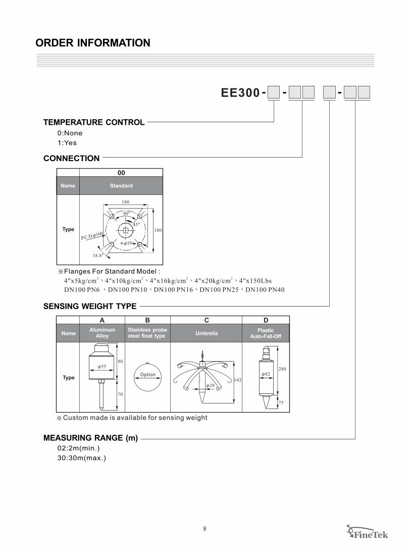
ORDER INFORMATION
8
0:None
1:Yes
TEMPERATURE CONTROL
SENSING WEIGHT TYPE
MEASURING RANGE (m)02:2m(min.)
30:30m(max.)
CONNECTION
EE300 - - -
Custom made is available for sensing weight
C D
142f20
f82280
75
A B
f55
70
Option
80
Aluminum Alloy
Plastic Auto-Fall-Off
Stainless probe steel float type UmbrellaName
Type
※2 2 2
4"x5kg/cm 4"x10kg/cm 4"x20kg/cm 150Lbs
DN100 PN6 DN100 PN10 DN100 PN16 DN100 PN25 DN100 PN40
Flanges For Standard Model :
、 、 、
、 、 、 、
、 24"x16kg/cm 4"x
Type
00
4-f19P.C.D.f160
180
90B
45B
18.8B
180
Name Standard

08-EE-B1-EP, 09/05/2011
FineTek Co., Ltd.
TEL: +886-2-2269-6789 FAX: +886-2-2268-6682Email: [email protected] http://www.fine-tek.com
Fine automation (ShangHai) Co., Ltd.No.451 DuHui Rd, MinHang District, Shanghai, China 201109TEL: +86-21-6490-7260 FAX: +86-21-6490-7276Email: [email protected]
FineTek Pte Ltd.No. 11 Kaki Bukit Road 1,#04-01 EunosTechnolink 415939, Singapore TEL: +65-6452-6340 FAX: +65-6734-1878Email: [email protected]
FineTeK GmbHFrankfurter Str. 62, OG D-65428 Ruesselsehim, GermanyTEL: +49-(0)6142-17608-0 FAX: +49-(0)6142-17608-20E-Mail: [email protected]
No.16, Tzuchiang St., Tucheng Industrial Park, New Taipei City 236, Taiwan
Distributor:
[SF] Paddle Flow Switch
[FC/FD] Mini Float/Magnetic Float Level Switch
[SD] Optical Level Switch
[FA/FB] Cable Float Level Switch
[FF] Side Mounting Float Switch
[SB] RF-Capacitance / Admittance Level Switch
[SE] Rotary Paddle Level Switch
[SC] Vibrating Probe Level Switch
[SC] Tuning Fork Level Switch
[LR] Loop Power Indicator
[SA] Capacitance Level Switch
[SP] Thermal Dispersion Flow Switch
[EC] Pressure Level Transmitter
[ED] Speed Monitor
[PB/PM] Microprocessor Based Bargraphic Display Scaling Meter
[BRD/AE] Valve and Controller for Dust Collector System
[EB] RF-Capacitance Level Transmitter
[FG] Magnetic Float Level Transmitter
[EG] Magnetostrictive Level Transmitter
[EA] Ultrasonic Level Transmitter
[EF] By-Pass Level Transmitter
[MEF] Mini By-Pass Level Transmitter
[BAS/BAH/BVP] Air Hammer
[BVK/BVR/BVT] Pneumatic Vibrator
[JFR] FMCW Radar Level Transmitter
[EE] Electromechanical Level Measuring System
[SRT/SRS] Conveyer Belt Misalignment Switch &
Safety Cable Pull Switch
[FA/FB]
[PB]
[EG]
[SF]
[EF]
[JFR] [FC/FD]
[EC]
[FF]
[SA]
[EB]
[EA]
[FG]
[SP]
[SC]
[SB]
[FC/FD] [SD]
[LR]
[EB]
[SE]
[PB/PM]
[EB]
[EE] [EA]
[BAS/BAH/BVP]
[BVK/BVR/BVT]
[EB]
[SA]
[SB]
[SC]
[SC]
[SC] [JFR] [SE]
[SB]


![20110224_Collaborate 0905[1]](https://static.fdocuments.in/doc/165x107/544a7691af7959a4438b4804/20110224collaborate-09051.jpg)