EDjunior Dynamometer and Crane Scale - dillon-force.com...The EDjr will store the peak force applied...
24
EDjunior Dynamometer and Crane Scale User Instructions AWT35-501286 Issue AA
Transcript of EDjunior Dynamometer and Crane Scale - dillon-force.com...The EDjr will store the peak force applied...

EDjunior Dynamometer and Crane Scale
User Instructions
AWT35-501286Issue AA

edjr_u_en_501286.book
Dillon is a trademark of the Illinois Tool Works group of companies whose ultimate parent company is Illinois Tool Works Inc (“Illinois Tool Works”). Copyright © 2014 Illinois Tool Works. All rights reserved.
No part of this publication may be reproduced by making a facsimile copy, by the making of a copy in three dimensions of a two-dimensional work and the making of a copy in two dimensions of a three-dimensional work, stored in any medium by electronic means, or transmitted in any form or by any means, including electronic, mechanical, broadcasting, recording or otherwise without the prior written consent of the copyright owner, under license, or as permitted by law.
This publication was correct at the time of going to print, however Avery Weigh-Tronix reserves the right to alter without notice the specification, design, price or conditions of supply of any product or service at any time.

EDjunior Dynamometer User Instructions 1
Table of ContentsChapter 1 General information and warnings ......................................................................................... 3
About this manual .............................................................................................................. 3Text conventions ......................................................................................................... 3Special messages ....................................................................................................... 3
Installation .......................................................................................................................... 4Safe handling of equipment with batteries .................................................................. 4
Safe Operation ................................................................................................................... 4Routine maintenance ......................................................................................................... 6Cleaning the machine ........................................................................................................ 6Training .............................................................................................................................. 6Sharp objects ..................................................................................................................... 6Declaration of Conformity .................................................................................................. 7
Chapter 2 Introduction ..............................................................................................................................8
Chapter 3 EDjr Description ....................................................................................................................... 9EDjr Front Panel ................................................................................................................ 9
EDjr Keys .................................................................................................................. 10
Chapter 4 Power On and Annunciators ................................................................................................. 11
Chapter 5 EDjr Setup ............................................................................................................................... 12Clock ................................................................................................................................ 12Setup>Misc ...................................................................................................................... 12Setup>About .................................................................................................................... 13Setup>Test ...................................................................................................................... 14
Chapter 6 EDjr Operation ........................................................................................................................ 15Display Modes ................................................................................................................. 15Force Measurement ......................................................................................................... 15Force Measurement Rezero ............................................................................................ 15Displaying Peak Force ..................................................................................................... 16Calculating Tension in a System ...................................................................................... 17
Chapter 7 Troubleshooting ..................................................................................................................... 18
Chapter 8 Weighing and Force Measurement Practice ........................................................................ 19Load Centering ................................................................................................................ 19Alignment ......................................................................................................................... 19Proper Pin Fit ................................................................................................................... 19Torque and Bending ........................................................................................................ 19Certified Gear ................................................................................................................... 19

2 EDjunior Dynamometer User Instructions

EDjunior Dynamometer User Instructions 3
1 General information and warnings
1.1 About this manual
This manual is divided into chapters by the chapter number and the large text at the top of a page. Subsections are labeled as shown by the 1 and 1.1 headings shown above. The names of the chapter and the next subsection level appear at the top of alternating pages of the manual to remind you of where you are in the manual. The manual name and page numbers appear at the bottom of the pages.
1.1.1 Text conventions
Key names are shown in bold and reflect the case of the key being described. This applies to hard keys and onscreen or soft keys.
Displayed messages appear in bold italic type and reflect the case of the displayed message.
1.1.2 Special messages
Examples of special messages you will see in this manual are defined below. The signal words have specific meanings to alert you to additional information or the relative level of hazard.
DANGER!THIS IS A DANGER SYMBOL.DANGER MEANS THAT FAILURE TO FOLLOW SPECIFIC PRACTICES OR PROCEDURES WILL CAUSE INJURY OR DEATH.
ELECTRICAL WARNING!THIS IS AN ELECTRICAL WARNING SYMBOL.ELECTRICAL WARNINGS MEAN THAT FAILURE TO FOLLOW SPECIFIC PRACTICES OR PROCEDURES MAY RESULT IN ELECTROCUTION, ARC BURNS, EXPLOSIONS OR OTHER HAZARDS THAT MAY CAUSE INJURY OR DEATH.
WARNING! This is a Warning symbol. Warnings mean that failure to follow specific practices and procedures may have major consequences such as injury or death.
CAUTION!This is a Caution symbol.Cautions give information about procedures that, if not observed, could result in damage to equipment or corruption to and loss of data.
4 EDjunior Dynamometer User Instructions
1.2 Installation
1.2.1 Safe handling of equipment with batteries
1.3 Safe Operation
Keep all the following in mind as you use the EDjr dynamometer.
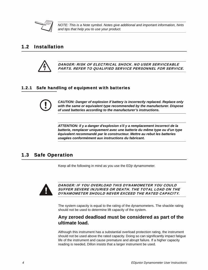
The system capacity is equal to the rating of the dynamometers. The shackle rating should not be used to determine lift capacity of the system.
Any zeroed deadload must be considered as part of the ultimate load.
Although this instrument has a substantial overload protection rating, the instrument should not be used above the rated capacity. Doing so can significantly impact fatigue life of the instrument and cause premature and abrupt failure. If a higher capacity reading is needed, Dillon insists that a larger instrument be used.
NOTE: This is a Note symbol. Notes give additional and important information, hints and tips that help you to use your product.
DANGER: RISK OF ELECTRICAL SHOCK. NO USER SERVICEABLE PARTS. REFER TO QUALIFIED SERVICE PERSONNEL FOR SERVICE.
CAUTION: Danger of explosion if battery is incorrectly replaced. Replace only with the same or equivalent type recommended by the manufacturer. Dispose of used batteries according to the manufacturer’s instructions.
ATTENTION: Il y a danger d'explosion s'il y a remplacement incorrect de la batterie, remplacer uniquement avec une batterie du même type ou d'un type équivalent recommandé par le constructeur. Mettre au rebut les batteries usagées conformément aux instructions du fabricant.
DANGER: IF YOU OVERLOAD THIS DYNAMOMETER YOU COULD SUFFER SEVERE INJURIES OR DEATH. THE TOTAL LOAD ON THE DYNAMOMETER SHOULD NEVER EXCEED THE RATED CAPACITY.

EDjunior Dynamometer User Instructions 5
Safety is always a concern in overhead lifting and tensioning applications. To limit your liability always insist upon factory supplied shackles and pins and factory tested and certified safe optional equipment. All DILLON products are designed to meet the published Safe Working Load (SWL) and Ultimate Safety Factor (USF) standards of the United States Military.
Do not grind, stamp or deform the metal on the dynamometer body in any way.
Any significant damage or deformation to the loading element is cause for evaluation by Dillon, particularly in the element side members to the right and left of the display.
Relieve all torsional and off axis loads.
Apply load in the center of the shackle bow with this instrument.
Off center loading results in substandard performance.
Instrument requires time to stabilize when changing temperatures.
Use only the hardware supplied with this instrument. If no hardware was supplied, insure that the mating pin and shackle bow is equivalent to the hardware used at calibration. Otherwise substandard performance can result.
This instrument is not designed for the following:
l Applications that see rapid, dramatic temperature swings or thermal shock. Wide variation in readings can occur.
l Environments with high electromagnetic fields such as cranes employing electromagnets to lift metal. These induce trace voltages that are picked up within the load cell lead wiring and appear as inaccurate loads.
l Intrinsically safe environments. This unit has not been Factory Mutual tested.
Dillon recommends only using qualified rigging hardware and cannot be responsible for unapproved hardware.

6 EDjunior Dynamometer User Instructions
1.4 Routine maintenance
1.5 Cleaning the machine
1.6 Training
Do not attempt to operate or complete any procedure on a machine unless you have received the appropriate training or read the instruction books.
To avoid the risk of RSI (Repetitive Strain Injury), place the machine on a surface which is ergonomically satisfactory to the user. Take frequent breaks during prolonged usage.
1.7 Sharp objects
Do not use sharp objects such as screwdrivers or long fingernails to operate the keys.
IMPORTANT: This equipment must be routinely checked for proper operation and calibration.Application and usage will determine the frequency of calibration required for safe operation.
Table 1.1 Cleaning DOs and DON’Ts
DO DO NOT
Wipe down the outside of standard products with a clean cloth, moistened with water and a small amount of mild detergent
Attempt to clean the inside of the machineUse harsh abrasives, solvents, scouring cleaners or alkaline cleaning solutions
Spray the cloth when using a proprietary cleaning fluid
Spray any liquid directly on to the display windows

EDjunior Dynamometer User Instructions 7
1.8 Declaration of Conformity

8 EDjunior Dynamometer User Instructions
2 IntroductionThe EDjuniorTM (EDjr) electronic dynamometer from Dillon is a force measurement load sensor and digital readout in one instrument. The EDjr can be used to measure tension or weight.
This manual covers the setup and operation of the EDjr. General information is covered in the right column of each page with major sections separated by the black bar shown above. Subheads appear in the left column along with any special notes, cautions or warnings.
This manual covers the following:
l EDjr Description
l EDjr Setup
l EDjr Operation
l Troubleshooting
Be sure to read the safety precautions found in the Safe Operation section.
DANGER: IF YOU OVERLOAD THIS DYNAMOMETER YOU COULD SUFFER SEVERE INJURIES OR DEATH. THE TOTAL LOAD ON THE DYNAMOMETER SHOULD NEVER EXCEED THE RATED CAPACITY.

EDjunior Dynamometer User Instructions 9
3 EDjr Description
3.1 EDjr Front Panel
The EDjr comes in several weight capacities. All have the same front panel, shown in Figure 3.1.
Figure 3.1 EDjunior front panel
ESC

10 EDjunior Dynamometer User Instructions
3.1.1 EDjr Keys
There are four “hard” keys and four “soft” keys. The hard keys are permanently labeled and the soft keys are just below the display. The soft key functions change and the key label appears above each key on the display. Sometimes the individual soft keys are referred to as the F1, F2, F3 and F4 keys as numbered from left to right.
On/Off key Use this key to turn the unit on and off.
ZERO key Use this key to zero the force indicated on the display.
ESC key Use this key to escape from portions of the menu structure and return to previous choices or displays.
Arrow key Use this key to access any available soft keys not currently viewed.
ESC
EDjunior Dynamometer User Instructions 11
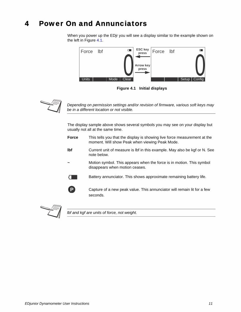
4 Power On and AnnunciatorsWhen you power up the EDjr you will see a display similar to the example shown on the left in Figure 4.1.
Figure 4.1 Initial displays
The display sample above shows several symbols you may see on your display but usually not all at the same time.
Force This tells you that the display is showing live force measurement at the moment. Will show Peak when viewing Peak Mode.
lbf Current unit of measure is lbf in this example. May also be kgf or N. See note below.
~ Motion symbol. This appears when the force is in motion. This symbol disappears when motion ceases.
Battery annunciator. This shows approximate remaining battery life.
Capture of a new peak value. This annunciator will remain lit for a few
seconds.
Force Forcelbf lbf
0 0ClearMode ConfigSetupUnits
Arrow keypress
ESC keypress
Depending on permission settings and/or revision of firmware, various soft keys may be in a different location or not visible.
P
lbf and kgf are units of force, not weight.

12 EDjunior Dynamometer User Instructions
5 EDjr SetupOne of the first things you should do to begin using the EDjr is to set it up to suit your specific needs and equipment. You can access the Setup menu, shown in Figure 5.1, using the soft keys. Press the appropriate soft key to accomplish the functions listed on the following pages.
Figure 5.1 Operator setup menu
5.1 Clock
Press the Clock key to change the date and time.
5.2 Setup>Misc
Press the Misc key to access the following soft key set (refer to Figure 3):
Flash Press this soft key to enable or disable the “display flash” feedback. If enabled, the press of a key causes the display to momentarily flash to give you a visual feedback that the key was activated.
Zero Press this soft key to enable or disable the Zero key’s ability to also clear the Peak force value. If you enable this function, press the Zero key to clear the Peak force and zero the load. If you disable the function, the Zero key will only zero the load. Peak force remains in effect and will only be cleared with the Clear function during operation.
Setup
Misc
O.Load ZeroCalib
About
Device
Software rev.link info
Lists #of overloads
List currentzero
compared againstcal zero
Points
Displaycalibration
points
Test
A-D
Test A-D
Disp.
Test display
Keys
Test keys
Batt
Test battery
Clock
Sets thetime and
date
Flash Zero Contr
Enable keypad display flash
Clearpeaks
on Zeropress
AdjustLCD
contrast
Blite
Adjustthe
backlight
Re-Cal
CalAlertDate
EDjunior Dynamometer User Instructions 13
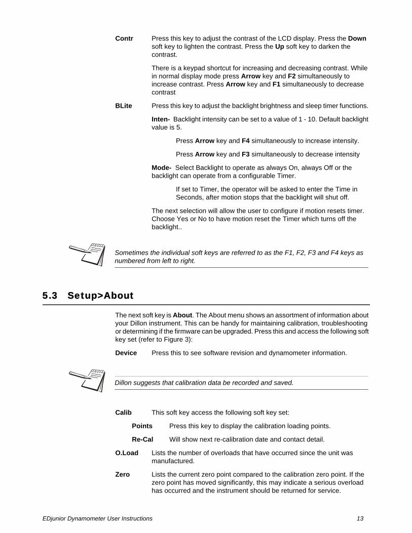
Contr Press this key to adjust the contrast of the LCD display. Press the Down soft key to lighten the contrast. Press the Up soft key to darken the contrast.
There is a keypad shortcut for increasing and decreasing contrast. While in normal display mode press Arrow key and F2 simultaneously to increase contrast. Press Arrow key and F1 simultaneously to decrease contrast
BLite Press this key to adjust the backlight brightness and sleep timer functions.
Inten- Backlight intensity can be set to a value of 1 - 10. Default backlight value is 5.
Press Arrow key and F4 simultaneously to increase intensity.
Press Arrow key and F3 simultaneously to decrease intensity
Mode- Select Backlight to operate as always On, always Off or the backlight can operate from a configurable Timer.
If set to Timer, the operator will be asked to enter the Time in Seconds, after motion stops that the backlight will shut off.
The next selection will allow the user to configure if motion resets timer. Choose Yes or No to have motion reset the Timer which turns off the backlight..
5.3 Setup>About
The next soft key is About. The About menu shows an assortment of information about your Dillon instrument. This can be handy for maintaining calibration, troubleshooting or determining if the firmware can be upgraded. Press this and access the following soft key set (refer to Figure 3):
Device Press this to see software revision and dynamometer information.
Calib This soft key access the following soft key set:
Points Press this key to display the calibration loading points.
Re-Cal Will show next re-calibration date and contact detail.
O.Load Lists the number of overloads that have occurred since the unit was manufactured.
Zero Lists the current zero point compared to the calibration zero point. If the zero point has moved significantly, this may indicate a serious overload has occurred and the instrument should be returned for service.
Sometimes the individual soft keys are referred to as the F1, F2, F3 and F4 keys as numbered from left to right.
Dillon suggests that calibration data be recorded and saved.

14 EDjunior Dynamometer User Instructions
5.4 Setup>Test
The Test functions can help service technicians remotely diagnose your Dillon instrument by showing information on key internal functions. Typically these menus will have significance only to trained technicians . You may look at these menus without technical guidance, but the information may have little meaning, or an error may be reported that may not exist.
Press this key to access several items described below (refer to Figure 5.1):
Batt Press this key to perform a battery test. This shows the battery level in A-D counts and approximate voltage. Voltage is not calibrated.
A-D Press this key to test the A-D section of the EDjr. You need to apply force to change the counts and test the unit. The A-D is the electronics portion that converts analog load cell signal to digital numbers.
Disp. Press this key to perform a display test. Stop the test by pressing the ESC key.
Keys Press this key to perform key tests. Any key pressed will be reflected in the display. Press to end the test.

EDjunior Dynamometer User Instructions 15
6 EDjr Operation
6.1 Display Modes
The EDjr has two display modes accessible by pressing the Mode soft key. See Figure 6.1.
The first display mode when you power up is the live force measurement mode.
Press the Mode soft key and the display changes to peak measurement mode. This mode shows the peak force applied to the EDjr since the last peak clearing action. Delete the peak reading by pressing the Clear soft key.
Press the Mode soft key again and the display returns to the force measurement mode.
6.2 Force Measurement
Follow these steps to perform a gross force measurement.
1. Turn on the unit with the On/Off key.
2. Remove any weight from the EDjr.
3. Zero the EDjr by pressing the ZERO key.
4. Apply the force to the EDjr and read the gross force on the display.
You can change the units of measure of the display by pressing the Units soft key. Zero reference is maintained after instrument power off and will be recalled with the next power-on. Zero reference may be lost if battery power is removed.
6.3 Force Measurement Rezero
Rezeroing allows the weight or load of fixturing to be invisible to the measurement. The zeroed load must always be considered as part of the maximum capacity.
1. Turn on the unit with the On/Off key.
2. Remove any weight from the EDjr.
3. Zero the EDjr by pressing the ZERO key.
4. Apply the tare force to the EDjr and press the ZERO key.
5. Apply the force to the EDjr and read the net force on the display.
Steps 2 and 3 are not required if the weight of the fixturing is not needed. This should be maintained, however, to know cumulative loads.

16 EDjunior Dynamometer User Instructions
6.4 Displaying Peak Force
The EDjr will store the peak force applied until that reading is cleared. To display the peak force applied to an EDjr, from the force measurement mode, press the Mode soft key. The display changes to display mode #2 shown in Figure 6.1 which is the peak display mode. The peak force is displayed. You can clear this by pressing the Clear soft key.
Peak reading is maintained after instrument power off and will be recalled with the next power-on. Peak reading may be lost if battery power is removed.
Figure 6.1 Display mode menu
Press the Mode soft key until the desired display mode is reached.
Peak force can only be reset to zero if live force is zero. Peak force will reset to match live force.
Force
Peak Peak
Forcelbf
lbf lbf
lbf
0
0
0
0Display #2Mode
Display Mode #1
Live forcereading
Peak forcereading
Arrow keypress
Mode keypress
Arrow keypress
ClearMode ConfigSetupUnits
ClearMode ConfigSetupUnits
ESC keypress
ESC keypress

EDjunior Dynamometer User Instructions 17
6.5 Calculating Tension in a System
The setup shown above will give you an approximate tension reading. This can vary from actual tension due to variables in equipment and environment.
Cable
T
T=2 cos
F
F
2
Truck Winch

18 EDjunior Dynamometer User Instructions
7 TroubleshootingProblem Possible Cause Solution
EDjr powers on momentarily and turns off
Low batteryBad keypad
Replace with high quality alkaline batteriesHave EDjr serviced
EDjr does not power on Low batteryBad keypad
Replace with high quality alkaline batteriesHave EDjr serviced
Batteries installed backwards or no spring contact
Insure that positive terminals of both batteries (nub) face inward – towards the black cap. Check that spring is attached to the battery cap.
Software reset Remove battery cap & reinstall after one minute. Attempt to turn power on again.
Display contrast too light Hold the Arrow key down while pressing the F2 key several times to increase the display contrast. If nothing occurs, release both keys. Press the power button and try again.
Display is completely dark Display contrast too dark Hold the Arrow key down while pressing the F1 key several times to decrease the display contrast.
Display flashes Low battery Replace with high quality alkaline batteries
EDjunior Dynamometer User Instructions 19
8 Weighing and Force Measurement PracticeThe basis for all electronic force measurement or weighing is measurement of stress in a loadcell body. To obtain optimal results it is necessary to establish a few basic rules, otherwise the effect may be a nonlinear or non-repeatable response. Read and follow these tips and see the illustrations on the next page.
8.1 Load Centering
For accurate performance the force acting on the unit must be in line with the unit.
8.2 Alignment
Insure shackles are oriented parallel with the instrument. Apply load in the center of the shackle bow.
8.3 Proper Pin Fit
A proper fitting pin is important in order to generate an even stress distribution and avoid yield stresses. To achieve published accuracy you must use the shackle pins provided by Dillon.
8.4 Torque and Bending
Torque and bending should be avoided. Use swivels on the lifting wire for anti-torque and avoid side forces.
8.5 Certified Gear
Certified shackles and lifting gear should always be used in accordance to local laws and federal legislation. Insure all hardware, fittings and line used to sustain the load are properly sized and rated for the installation. Have the system evaluated by a qualified engineer if any question or uncertainty exists.

20 EDjunior Dynamometer User Instructions
Figure 8.1 Good force measurement practice
Center the loadon the shackle pin.
Use spacers toinsure centering
where applicable.
Use only witha pin of the
same diameterand hardnessas the original
factory equipment.
Do not torque, bend or
sideload.
Use hardware that allowssingle point attachment
and freedom of alignment.Do not use hardware that is undersize or restricts
self-alignment. This results inpoor measurement
performance and possible dangerous safety conditions.
Be sure fixturing does not bind between the body of the EDjr and
the shackle!


Overload Protection and Overhead Weighing Equipment
Fairmont, Minnesota U.S.A.
Toll-Free: (800) 368-2031Phone: (507) 238-4461Fax: (507) 238-8258www.dillon-force.com
AUTHORIZED DISTRIBUTORS
Ask the experts. Dillon distributors offer complete service capabilities from application assistance to sales and product support. Their experienced representatives are the most knowledgeable experts that you will find in the force measurement industry. We recommend that you consult these capable specialists for all of your measuring needs.


![Northumbria Research Linknrl.northumbria.ac.uk/38866/1/Paper_1.pdf · Peak Shaving and Load Shedding Peak shaving as a tool for DSM was applied in [19, 20], while load shifting and](https://static.fdocuments.in/doc/165x107/5e86d91a422c647a4354706c/northumbria-research-peak-shaving-and-load-shedding-peak-shaving-as-a-tool-for-dsm.jpg)