EDjunior Dynamometer User’s Manual · 6 EDjunior Dynamometer User’s Manual On/Off key Use this...
16
EDjunior Dynamometer User’s Manual
Transcript of EDjunior Dynamometer User’s Manual · 6 EDjunior Dynamometer User’s Manual On/Off key Use this...

EDjunior DynamometerUser’s Manual

2 EDjunior Dynamometer User’s ManualWeigh Bar® is a registered trademark of Weigh-Tronix Inc.
05/16/06 EDJR_U.P65 PN 29810-0017D e1 Printed in USA

3EDjunior Dynamometer User’s Manual
Table of Contents
Table of Contents ........................................................................................................................ 3Introduction ................................................................................................................................. 5EDjr Description .......................................................................................................................... 5
EDjr Front Panel ................................................................................................................... 5Power On and Annunciators ........................................................................................................ 7EDjr Setup ................................................................................................................................. 7EDjr Operation ........................................................................................................................... 11
Display Modes .................................................................................................................... 11Force Measurement ............................................................................................................ 11Force Measurement Rezero ............................................................................................... 11Displaying Peak Force ........................................................................................................ 11
Troubleshooting ......................................................................................................................... 13Safe Operation .......................................................................................................................... 14Weigh and Force Measurement Practice .................................................................................. 15
Load Centering ................................................................................................................... 15Alignment ............................................................................................................................ 15Proper Pin Fit ...................................................................................................................... 15Torque and Bending ........................................................................................................... 15Certified Gear...................................................................................................................... 15Good Force Measurement Practice .................................................................................... 16

4 EDjunior Dynamometer User’s Manual

5EDjunior Dynamometer User’s Manual
IntroductionThe EDjuniorTM (EDjr) electronic dynamometer from Dillon is a force mea-surement load sensor and digital readout in one instrument. The EDjr can beused to measure tension or weight.
This manual covers the setup and operation of the EDjr. General informationis covered in the right column of each page with major sections separatedby the black bar shown above. Subheads appear in the left column alongwith any special notes, cautions or warnings.
This manual covers the following:
• EDjr Description• EDjr Setup• EDjr Operation• Troubleshooting
Be sure to read the safety precautions found in the Safe Operation section.
The EDjr comes in several weight capacities. All have the same front panel,shown in Figure 1.
Figure 1EDjunior front panel
There are four “hard” keys and four “soft” keys. The hard keys are perma-nently labeled and the soft keys are just below the display. The soft keyfunctions change and the key label appears above each key on the display.Sometimes the individual soft keys are referred to as the F1, F2, F3 andF4 keys as numbered from left to right.
EDjr DescriptionEDjr Front Panel
EDjr Keys
If you overload this dynamom-eter you could suffer severeinjuries or death. The total loadon the dynamometer shouldNEVER exceed the ratedcapacity.

6 EDjunior Dynamometer User’s Manual
On/Off key Use this key to turn the unit on and off.
ZERO key Use this key to zero the force indicatedon the display.
ESC key Use this key to escape from portions ofthe menu structure and return to previ-ous choices or displays.
Arrow key Use this key to access any available softkeys not currently viewed.
If lift hardware (shackles,chains, beams, hoppers, etc.)is used to support the load andzeroed prior to lifting thecurrent load being displayed,you can press the ZERO keyfor five seconds, the displaywill show the total load beinglifted based on the zero pointused in calibrating the EDjr.

7EDjunior Dynamometer User’s Manual
Power On and AnnunciatorsWhen you power up the EDjr you will see a display similar to the exampleshown on the left in Figure 2.
Figure 2Initial displays
The display sample above shows several symbols you may see on yourdisplay but usually not all at the same time.
Force This tells you that the display is showing live force measurementat the moment. Will show Peak when viewing Peak Mode.
lbf Current unit of measure is lbf in this example. May also be kgfor N.
~ Motion symbol. This appears when the force is in motion. Thissymbol disappears when motion ceases.
Battery annunciator. This shows approximate remaining batterylife.
Capture of a new peak value. This annunciator will remain lit fora few seconds.
Depending on permissionsettings and/or revision offirmware, various soft keysmay be in a different location ornot visible.
lbf and kgf are units of force,not weight. They will be closeto their mass counterparts, lband kg, for most applicationsand at most locations.
P

8 EDjunior Dynamometer User’s Manual
Figure 3Operator setup menu for the EDjunior
EDjr SetupOne of the first things you should do to begin using the EDjr is to set it up tosuit your specific needs and equipment. You can access the Setup menu,shown in Figure 3, using the soft keys. Press the appropriate soft key toaccomplish the functions listed on the following pages.

9EDjunior Dynamometer User’s Manual
SetupMisc
Press the Misc key to access the following soft key set (refer to Figure 3):
Flash Press this soft key to enable or disable the “display flash”feedback. If enabled, the press of a key causes the display tomomentarily flash to give you a visual feedback that the key wasactivated.
Zero Press this soft key to enable or disable the Zero key’s ability toalso clear the Peak force value. If you enable this function,press the Zero key to clear the Peak force and zero the load. Ifyou disable the function, the Zero key will only zero the load.Peak force remains in effect and will only be cleared with theClear function during operation.
Contr Press this key to adjust the contrast of the LCD display. Pressthe Down soft key to lighten the contrast. Press the Up soft keyto darken the contrast.
There is a keypad shortcut for increasing and decreasingcontrast. While in normal display mode press Arrow key and F2simultaneously to increase contrast. Press Arrow key and F1simultaneously to decrease contrast.
The next soft key is the About. The About menu shows an assortment ofinformation about your Dillon instrument. This can be handy for maintainingcalibration, troubleshooting or determining if the firmware can be upgraded.Press this and access the following soft key set (refer to Figure 3):
Device Press this to see software revision and dynamometer informa-tion.
Calib This soft key access the following soft key set:
Points Press this key to display the calibration loading points.
SetupAbout
Dillon suggests that calibrationdata be recorded and saved.
Sometimes the individualsoft keys are referred to asthe F1, F2, F3 and F4 keys asnumbered from left to right.

10 EDjunior Dynamometer User’s Manual
SetupTest
O.Load Lists the number of overloads that have occurred since the unitwas manufactured.
Zero Lists the current zero point compared to the calibration zeropoint. If the zero point has moved significantly, this may indicatea serious overload has occurred and the instrument should bereturned for service.
The Test functions can help service technicians remotely diagnose yourDillon instrument by showing information on key internal functions. Typicallythese menus will have significance only to trained technicians . You maylook at these menus without technical guidance, but the information mayhave little meaning, or an error may be reported that may not exist.
Press this key to access several items described below (refer to Figure 3):
Batt Press this key to perform a battery test. This shows the batterylevel in A-D counts and approximate voltage. Voltage is notcalibrated.
A-D Press this key to test the A-D section of the EDjr. You need toapply force to change the counts and test the unit. The A-D isthe electronics portion that converts analog load cell signal todigital numbers.
Disp. Press this key to perform a display test. Stop the test by press-ing the ESC key.
Keys Press this key to perform key tests. Any key pressed will bereflected in the display. Press ESC to end the test.

11EDjunior Dynamometer User’s Manual
EDjr Operation
Display Modes The EDjr has two display modes accessible by pressing the Mode soft key.See Figure 4.
The first display mode when you power up is the live force measurementmode.
Press the Mode soft key and the display changes to peak measurementmode. This mode shows the peak force applied to the EDjr since the lastpeak clearing action. Delete the peak reading by pressing the Clear soft key.
Press the Mode soft key again and the display returns to the force measure-ment mode.
Follow these steps to perform a gross force measurement.
1. Turn on the unit with the On/Off key.
2. Remove any weight from the EDjr.
3. Zero the EDjr by pressing the ZERO key.
4. Apply the force to the EDjr and read the gross force on the display.
You can change the units of measure of the display by pressing the Unitssoft key. Zero reference is maintained after instrument power off and will berecalled with the next power-on. Zero reference may be lost if battery poweris removed.
Rezeroing allows the weight or load of fixturing to be invisible to the mea-surement. The zeroed load must always be considered as part of themaximum capacity.
1. Turn on the unit with the On/Off key.
2. Remove any weight from the EDjr.
3. Zero the EDjr by pressing the ZERO key.
4. Apply the tare force to the EDjr and press the ZERO key.
5. Apply the force to the EDjr and read the net force on the display.
Steps 2 and 3 are not required if the weight of the fixturing is not needed.This should be maintained, however, to know cumulative loads.
The EDjr will store the peak force applied until that reading is cleared. Todisplay the peak force applied to an EDjr, from the force measurementmode, press the Mode soft key. The display changes to display mode #2shown in Figure 4 which is the peak display mode. The peak force is dis-played. You can clear this by pressing the Clear soft key.
Peak reading is maintained after instrument power off and will be recalledwith the next power-on. Peak reading may be lost if battery power is re-moved.
Force Measurement
Force MeasurementRezero
Displaying Peak Force
Peak force can only be reset tozero if live force is zero. Peakforce will reset to match liveforce.

12 EDjunior Dynamometer User’s Manual
Figure 4Display mode menu
Press the Mode soft key until the desired display mode is reached.

13EDjunior Dynamometer User’s Manual
Troubleshooting
SolutionReplace with high quality alkaline batteries
Replace with high quality alkaline batteries
Insure that positive terminals of both batteries (nub)face inward – towards the black cap. Check thatspring is attached to the battery cap.
Remove battery cap & reinstall after one minute.Attempt to turn power on again.
Hold the Arrow key down while pressing the F2 keyseveral times to increase the display contrast. Ifnothing occurs, release both keys. Press the powerbutton and try again.
Hold the Right Arrow key down while pressing theF1 key several times to decrease the display con-trast.
ProblemEDjr powers on momen-tarily and turns off
EDjr does not power on
Display is completelydark
Possible CauseLow battery
Low battery
Batteries installed back-wards or no spring contact
Software reset
Display contrast too light
Display contrast too dark

14 EDjunior Dynamometer User’s Manual
Keep all the following in mind as you use the EDjr dynamometer.
The system capacity is equal to the rating of the dynamometers. Theshackle rating should not be used to determine lift capacity of the system.
Any zeroed deadload must be considered as partof the ultimate load.
Although this instrument has a substantial overload protection rating, theinstrument should not be used above the rated capacity. Doing so cansignificantly impact fatigue life of the instrument and cause premature andabrupt failure. If a higher capacity reading is needed, Dillon insists that alarger instrument be used.
Safety is always a concern in overhead lifting and tensioning applications.To limit your liability always insist upon factory supplied shackles and pinsand factory tested and certified safe optional equipment. All DILLON prod-ucts are designed to meet the published Safe Working Load (SWL) andUltimate Safety Factor (USF) standards of the United States Military.
Do not grind, stamp or deform the metal on the dynamometer body in anyway.
Any significant damage or deformation to the loading element is cause forevaluation by Dillon, particularly in the element side members to the rightand left of the display.
Relieve all torsional and off axis loads.
Apply load in the center of the shackle bow with this instrument.
Off center loading results in substandard performance.
Instrument requires time to stabilize when changing temperatures.
Use only the hardware supplied with this instrument. If no hardware wassupplied, insure that the mating pin and shackle bow is equivalent to thehardware used at calibration. Otherwise substandard performance canresult.
Dillon recommends only using qualified rigging hardware and cannotbe responsible for unapproved hardware.
This instrument is not designed for the following:
• Applications that see rapid, dramatic temperature swings or thermalshock. Wide variation in readings can occur.
• Environments with high electromagnetic fields such as cranes employ-ing electromagnets to lift metal. These induce trace voltages that arepicked up within the load cell lead wiring and appear as inaccurateloads.
• Intrinsically safe environments. This unit has not been Factory Mutualtested.
Safe Operation
If you overload this dynamom-eter you could suffer severeinjuries or death. The total loadon the dynamometer shouldNEVER exceed the ratedcapacity.
15EDjunior Dynamometer User’s Manual
Torque and Bending
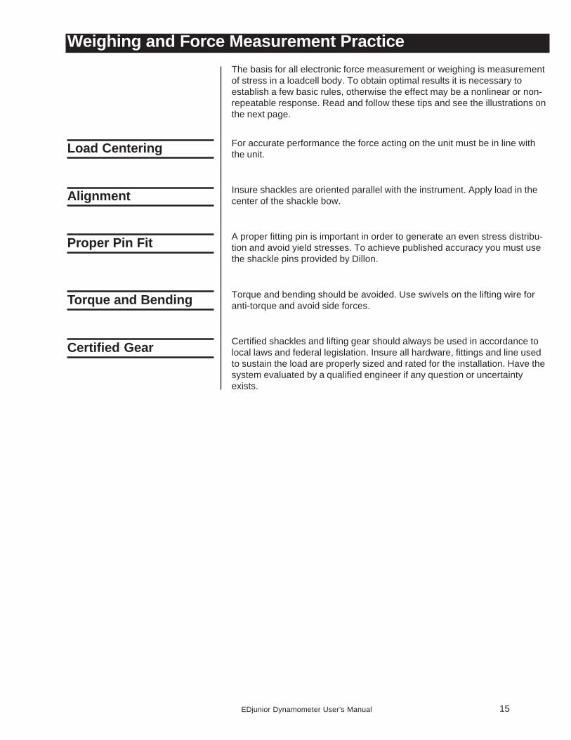
Weighing and Force Measurement PracticeThe basis for all electronic force measurement or weighing is measurementof stress in a loadcell body. To obtain optimal results it is necessary toestablish a few basic rules, otherwise the effect may be a nonlinear or non-repeatable response. Read and follow these tips and see the illustrations onthe next page.
For accurate performance the force acting on the unit must be in line withthe unit.
Insure shackles are oriented parallel with the instrument. Apply load in thecenter of the shackle bow.
A proper fitting pin is important in order to generate an even stress distribu-tion and avoid yield stresses. To achieve published accuracy you must usethe shackle pins provided by Dillon.
Torque and bending should be avoided. Use swivels on the lifting wire foranti-torque and avoid side forces.
Certified shackles and lifting gear should always be used in accordance tolocal laws and federal legislation. Insure all hardware, fittings and line usedto sustain the load are properly sized and rated for the installation. Have thesystem evaluated by a qualified engineer if any question or uncertaintyexists.
Load Centering
Proper Pin Fit
Certified Gear
Alignment
16 EDjunior Dynamometer User’s Manual
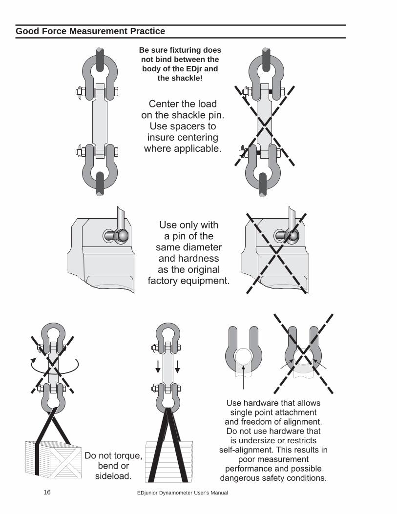
Good Force Measurement Practice
Be sure fixturing doesnot bind between thebody of the EDjr and
the shackle!