Quantum using EcoStruxure™ Control Expert - Discrete and ...

EcoStruxure Machine Expert - Basic
EIO0000003281 12/2018
EIO
0000
0032
81.0
0
www.schneider-electric.com
EcoStruxure Machine Expert - BasicOperating Guide12/2018

The information provided in this documentation contains general descriptions and/or technical characteristics of the performance of the products contained herein. This documentation is not intended as a substitute for and is not to be used for determining suitability or reliability of these products for specific user applications. It is the duty of any such user or integrator to perform the appropriate and complete risk analysis, evaluation and testing of the products with respect to the relevant specific application or use thereof. Neither Schneider Electric nor any of its affiliates or subsidiaries shall be responsible or liable for misuse of the information contained herein. If you have any suggestions for improvements or amendments or have found errors in this publication, please notify us. You agree not to reproduce, other than for your own personal, noncommercial use, all or part of this document on any medium whatsoever without permission of Schneider Electric, given in writing. You also agree not to establish any hypertext links to this document or its content. Schneider Electric does not grant any right or license for the personal and noncommercial use of the document or its content, except for a non-exclusive license to consult it on an "as is" basis, at your own risk. All other rights are reserved.All pertinent state, regional, and local safety regulations must be observed when installing and using this product. For reasons of safety and to help ensure compliance with documented system data, only the manufacturer should perform repairs to components.When devices are used for applications with technical safety requirements, the relevant instructions must be followed. Failure to use Schneider Electric software or approved software with our hardware products may result in injury, harm, or improper operating results.Failure to observe this information can result in injury or equipment damage.© 2018 Schneider Electric. All rights reserved.
2 EIO0000003281 12/2018

Table of Contents
Safety Information. . . . . . . . . . . . . . . . . . . . . . . . . . . . . . 9About the Book . . . . . . . . . . . . . . . . . . . . . . . . . . . . . . . . 11
Part I Getting Started with EcoStruxure Machine Expert - Basic . . . . . . . . . . . . . . . . . . . . . . . . . . . . . . . . . . . . . 19
Chapter 1 Introduction to EcoStruxure Machine Expert - Basic . . . 211.1 System Requirements and Supported Devices. . . . . . . . . . . . . . . . . . 22
System Requirements . . . . . . . . . . . . . . . . . . . . . . . . . . . . . . . . . . . . . 23Supported Devices . . . . . . . . . . . . . . . . . . . . . . . . . . . . . . . . . . . . . . . 24Supported Programming Languages. . . . . . . . . . . . . . . . . . . . . . . . . . 26
1.2 EcoStruxure Machine Expert - Basic User Interface Basics . . . . . . . . 27Creating Projects With EcoStruxure Machine Expert - Basic . . . . . . . 28Developing Programs With EcoStruxure Machine Expert - Basic . . . . 29Navigating Within EcoStruxure Machine Expert - Basic . . . . . . . . . . . 30Operating Modes . . . . . . . . . . . . . . . . . . . . . . . . . . . . . . . . . . . . . . . . . 31
1.3 The Start Menu . . . . . . . . . . . . . . . . . . . . . . . . . . . . . . . . . . . . . . . . . . 32Introduction to the Start Menu . . . . . . . . . . . . . . . . . . . . . . . . . . . . . . . 33Registering the EcoStruxure Machine Expert - Basic Software . . . . . 34Open Project Window . . . . . . . . . . . . . . . . . . . . . . . . . . . . . . . . . . . . . 35Project Templates Window . . . . . . . . . . . . . . . . . . . . . . . . . . . . . . . . . 38Help Window . . . . . . . . . . . . . . . . . . . . . . . . . . . . . . . . . . . . . . . . . . . . 39
Part II Developing EcoStruxure Machine Expert - Basic Applications . . . . . . . . . . . . . . . . . . . . . . . . . . . . . . . 41
Chapter 2 The EcoStruxure Machine Expert - Basic Window . . . . . 432.1 Overview of the EcoStruxure Machine Expert - Basic Window . . . . . . 44
Toolbar Buttons . . . . . . . . . . . . . . . . . . . . . . . . . . . . . . . . . . . . . . . . . . 45Status Area . . . . . . . . . . . . . . . . . . . . . . . . . . . . . . . . . . . . . . . . . . . . . 47System Settings. . . . . . . . . . . . . . . . . . . . . . . . . . . . . . . . . . . . . . . . . . 49Print Reports . . . . . . . . . . . . . . . . . . . . . . . . . . . . . . . . . . . . . . . . . . . . 51
Chapter 3 Properties . . . . . . . . . . . . . . . . . . . . . . . . . . . . . . . . . . . 533.1 Overview of the Properties Window . . . . . . . . . . . . . . . . . . . . . . . . . . 54
The Properties Window . . . . . . . . . . . . . . . . . . . . . . . . . . . . . . . . . . . . 55Project Properties . . . . . . . . . . . . . . . . . . . . . . . . . . . . . . . . . . . . . . . . 56
EIO0000003281 12/2018 3

Chapter 4 Configuration . . . . . . . . . . . . . . . . . . . . . . . . . . . . . . . . . . 594.1 Overview of the Configuration Window . . . . . . . . . . . . . . . . . . . . . . . . 60
Overview of the Configuration Window . . . . . . . . . . . . . . . . . . . . . . . . 61Building a Configuration . . . . . . . . . . . . . . . . . . . . . . . . . . . . . . . . . . . . 62
Chapter 5 Programming . . . . . . . . . . . . . . . . . . . . . . . . . . . . . . . . . . 635.1 Overview of the Programming Workspace. . . . . . . . . . . . . . . . . . . . . . 64
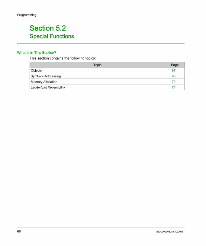
Overview of the Programming Workspace. . . . . . . . . . . . . . . . . . . . . . 645.2 Special Functions. . . . . . . . . . . . . . . . . . . . . . . . . . . . . . . . . . . . . . . . . 66
Objects . . . . . . . . . . . . . . . . . . . . . . . . . . . . . . . . . . . . . . . . . . . . . . . . . 67Symbolic Addressing . . . . . . . . . . . . . . . . . . . . . . . . . . . . . . . . . . . . . . 68Memory Allocation . . . . . . . . . . . . . . . . . . . . . . . . . . . . . . . . . . . . . . . . 70Ladder/List Reversibility . . . . . . . . . . . . . . . . . . . . . . . . . . . . . . . . . . . . 71
5.3 Configuring Program Behavior and Tasks . . . . . . . . . . . . . . . . . . . . . . 76Application Behavior . . . . . . . . . . . . . . . . . . . . . . . . . . . . . . . . . . . . . . 77Tasks and Scan Modes . . . . . . . . . . . . . . . . . . . . . . . . . . . . . . . . . . . . 82
5.4 Managing POUs. . . . . . . . . . . . . . . . . . . . . . . . . . . . . . . . . . . . . . . . . . 85POUs . . . . . . . . . . . . . . . . . . . . . . . . . . . . . . . . . . . . . . . . . . . . . . . . . . 86Managing POUs with Tasks. . . . . . . . . . . . . . . . . . . . . . . . . . . . . . . . . 87Managing Rungs . . . . . . . . . . . . . . . . . . . . . . . . . . . . . . . . . . . . . . . . . 90Managing Grafcet (SFC) POUs . . . . . . . . . . . . . . . . . . . . . . . . . . . . . . 93Free POUs . . . . . . . . . . . . . . . . . . . . . . . . . . . . . . . . . . . . . . . . . . . . . . 95
5.5 User-Defined Functions . . . . . . . . . . . . . . . . . . . . . . . . . . . . . . . . . . . . 99Creating a User-Defined Function . . . . . . . . . . . . . . . . . . . . . . . . . . . . 100Defining a User-Defined Function . . . . . . . . . . . . . . . . . . . . . . . . . . . . 101Managing User-Defined Functions. . . . . . . . . . . . . . . . . . . . . . . . . . . . 105
5.6 User-Defined Function Blocks . . . . . . . . . . . . . . . . . . . . . . . . . . . . . . . 107Creating a User-Defined Function Block . . . . . . . . . . . . . . . . . . . . . . . 108Defining a User-Defined Function Block . . . . . . . . . . . . . . . . . . . . . . . 109Managing User-Defined Function Blocks. . . . . . . . . . . . . . . . . . . . . . . 113
5.7 Master Task . . . . . . . . . . . . . . . . . . . . . . . . . . . . . . . . . . . . . . . . . . . . . 115Master Task Description . . . . . . . . . . . . . . . . . . . . . . . . . . . . . . . . . . . 116Configuring Master Task . . . . . . . . . . . . . . . . . . . . . . . . . . . . . . . . . . . 117
5.8 Strings . . . . . . . . . . . . . . . . . . . . . . . . . . . . . . . . . . . . . . . . . . . . . . . . . 119Configuring Strings in Constant words. . . . . . . . . . . . . . . . . . . . . . . . . 120Assigning Strings in Memory Words . . . . . . . . . . . . . . . . . . . . . . . . . . 121Managing Strings . . . . . . . . . . . . . . . . . . . . . . . . . . . . . . . . . . . . . . . . . 122
4 EIO0000003281 12/2018
5.9 Periodic Task. . . . . . . . . . . . . . . . . . . . . . . . . . . . . . . . . . . . . . . . . . . . 125Creating Periodic Task . . . . . . . . . . . . . . . . . . . . . . . . . . . . . . . . . . . . 126Configuring Periodic Task Scan Duration . . . . . . . . . . . . . . . . . . . . . . 128
5.10 Event Task. . . . . . . . . . . . . . . . . . . . . . . . . . . . . . . . . . . . . . . . . . . . . . 129Overview of Event Tasks. . . . . . . . . . . . . . . . . . . . . . . . . . . . . . . . . . . 130Event Sources . . . . . . . . . . . . . . . . . . . . . . . . . . . . . . . . . . . . . . . . . . . 131Event Priorities . . . . . . . . . . . . . . . . . . . . . . . . . . . . . . . . . . . . . . . . . . 132Viewing Event Tasks . . . . . . . . . . . . . . . . . . . . . . . . . . . . . . . . . . . . . . 133
5.11 Using Tools . . . . . . . . . . . . . . . . . . . . . . . . . . . . . . . . . . . . . . . . . . . . . 136Messages . . . . . . . . . . . . . . . . . . . . . . . . . . . . . . . . . . . . . . . . . . . . . . 137Animation Tables. . . . . . . . . . . . . . . . . . . . . . . . . . . . . . . . . . . . . . . . . 139Memory Objects . . . . . . . . . . . . . . . . . . . . . . . . . . . . . . . . . . . . . . . . . 145System Objects . . . . . . . . . . . . . . . . . . . . . . . . . . . . . . . . . . . . . . . . . . 150I/O Objects. . . . . . . . . . . . . . . . . . . . . . . . . . . . . . . . . . . . . . . . . . . . . . 151Network Objects . . . . . . . . . . . . . . . . . . . . . . . . . . . . . . . . . . . . . . . . . 152Software Objects . . . . . . . . . . . . . . . . . . . . . . . . . . . . . . . . . . . . . . . . . 153PTO Objects . . . . . . . . . . . . . . . . . . . . . . . . . . . . . . . . . . . . . . . . . . . . 154Drive Objects . . . . . . . . . . . . . . . . . . . . . . . . . . . . . . . . . . . . . . . . . . . . 155Communication Objects . . . . . . . . . . . . . . . . . . . . . . . . . . . . . . . . . . . 156Search and Replace . . . . . . . . . . . . . . . . . . . . . . . . . . . . . . . . . . . . . . 157Cross Reference . . . . . . . . . . . . . . . . . . . . . . . . . . . . . . . . . . . . . . . . . 159Symbol List . . . . . . . . . . . . . . . . . . . . . . . . . . . . . . . . . . . . . . . . . . . . . 160Memory Consumption View. . . . . . . . . . . . . . . . . . . . . . . . . . . . . . . . . 165
5.12 Ladder Language Programming . . . . . . . . . . . . . . . . . . . . . . . . . . . . . 167Introduction to Ladder Diagrams . . . . . . . . . . . . . . . . . . . . . . . . . . . . . 168Programming Principles for Ladder Diagrams. . . . . . . . . . . . . . . . . . . 170Color Coding of Rungs . . . . . . . . . . . . . . . . . . . . . . . . . . . . . . . . . . . . 172Ladder Diagram Graphic Elements . . . . . . . . . . . . . . . . . . . . . . . . . . . 174Comparison Blocks . . . . . . . . . . . . . . . . . . . . . . . . . . . . . . . . . . . . . . . 181Operation Blocks . . . . . . . . . . . . . . . . . . . . . . . . . . . . . . . . . . . . . . . . . 182Adding Comments . . . . . . . . . . . . . . . . . . . . . . . . . . . . . . . . . . . . . . . . 186Programming Best Practices . . . . . . . . . . . . . . . . . . . . . . . . . . . . . . . . 187
5.13 Instruction List Programming. . . . . . . . . . . . . . . . . . . . . . . . . . . . . . . . 190Overview of Instruction List Programs. . . . . . . . . . . . . . . . . . . . . . . . . 191Operation of List Instructions. . . . . . . . . . . . . . . . . . . . . . . . . . . . . . . . 194List Language Instructions. . . . . . . . . . . . . . . . . . . . . . . . . . . . . . . . . . 195Using Parentheses . . . . . . . . . . . . . . . . . . . . . . . . . . . . . . . . . . . . . . . 199
EIO0000003281 12/2018 5
5.14 Grafcet (List) Programming . . . . . . . . . . . . . . . . . . . . . . . . . . . . . . . . . 202Description of Grafcet (List) Programming. . . . . . . . . . . . . . . . . . . . . . 203Grafcet (List) Program Structure . . . . . . . . . . . . . . . . . . . . . . . . . . . . . 204How to Use Grafcet (List) Instructions in an EcoStruxure Machine Expert - Basic Program . . . . . . . . . . . . . . . . . . . . . . . . . . . . . . . . . . . . 208
5.15 Grafcet (SFC) Programming . . . . . . . . . . . . . . . . . . . . . . . . . . . . . . . . 210Introduction to Grafcet (SFC) Programming . . . . . . . . . . . . . . . . . . . . 211Using the Grafcet (SFC) Graphical Editor . . . . . . . . . . . . . . . . . . . . . . 214Branching . . . . . . . . . . . . . . . . . . . . . . . . . . . . . . . . . . . . . . . . . . . . . . . 219Programming Best Practices . . . . . . . . . . . . . . . . . . . . . . . . . . . . . . . . 223
5.16 Debugging in Online Mode. . . . . . . . . . . . . . . . . . . . . . . . . . . . . . . . . . 225Trace Window . . . . . . . . . . . . . . . . . . . . . . . . . . . . . . . . . . . . . . . . . . . 226Modifying Values . . . . . . . . . . . . . . . . . . . . . . . . . . . . . . . . . . . . . . . . . 229Forcing Values . . . . . . . . . . . . . . . . . . . . . . . . . . . . . . . . . . . . . . . . . . . 230Online Mode Modifications. . . . . . . . . . . . . . . . . . . . . . . . . . . . . . . . . . 231
Chapter 6 Commissioning. . . . . . . . . . . . . . . . . . . . . . . . . . . . . . . . . 2396.1 Overview of the Commissioning Window. . . . . . . . . . . . . . . . . . . . . . . 240
Overview of the Commissioning Window. . . . . . . . . . . . . . . . . . . . . . . 2406.2 Connect to a Logic Controller . . . . . . . . . . . . . . . . . . . . . . . . . . . . . . . 241
Connecting to a Logic Controller . . . . . . . . . . . . . . . . . . . . . . . . . . . . . 242Downloading and Uploading Applications . . . . . . . . . . . . . . . . . . . . . . 249
6.3 Controller Update . . . . . . . . . . . . . . . . . . . . . . . . . . . . . . . . . . . . . . . . . 253Controller Firmware Updates . . . . . . . . . . . . . . . . . . . . . . . . . . . . . . . . 253
6.4 Memory Management . . . . . . . . . . . . . . . . . . . . . . . . . . . . . . . . . . . . . 254Managing Logic Controller Memory . . . . . . . . . . . . . . . . . . . . . . . . . . . 254
6.5 Controller Info. . . . . . . . . . . . . . . . . . . . . . . . . . . . . . . . . . . . . . . . . . . . 260Controller Information. . . . . . . . . . . . . . . . . . . . . . . . . . . . . . . . . . . . . . 260
6.6 RTC Management . . . . . . . . . . . . . . . . . . . . . . . . . . . . . . . . . . . . . . . . 262Managing the RTC. . . . . . . . . . . . . . . . . . . . . . . . . . . . . . . . . . . . . . . . 262
Chapter 7 Simulator . . . . . . . . . . . . . . . . . . . . . . . . . . . . . . . . . . . . . 263Overview of the EcoStruxure Machine Expert - Basic Simulator . . . . . 264EcoStruxure Machine Expert - Basic Simulator I/O Manager Window 266EcoStruxure Machine Expert - Basic Simulator Time Management Window . . . . . . . . . . . . . . . . . . . . . . . . . . . . . . . . . . . . . . . . . . . . . . . . 268Modifying Values Using EcoStruxure Machine Expert - Basic Simulator 271How to Use the EcoStruxure Machine Expert - Basic Simulator . . . . . 275Launching Simulation in Vijeo-Designer . . . . . . . . . . . . . . . . . . . . . . . 276
6 EIO0000003281 12/2018

Chapter 8 Saving Projects and Closing EcoStruxure Machine Expert - Basic. . . . . . . . . . . . . . . . . . . . . . . . . . . . . . . . . . . . . . . 277Saving a Project . . . . . . . . . . . . . . . . . . . . . . . . . . . . . . . . . . . . . . . . . 278Saving a Project As a Template . . . . . . . . . . . . . . . . . . . . . . . . . . . . . 279Closing EcoStruxure Machine Expert - Basic . . . . . . . . . . . . . . . . . . . 280
Appendices . . . . . . . . . . . . . . . . . . . . . . . . . . . . . . . . . . . . . . . . . 281Appendix A Converting Twido Projects to EcoStruxure Machine
Expert - Basic . . . . . . . . . . . . . . . . . . . . . . . . . . . . . . . . . 283Converting Twido Projects to EcoStruxure Machine Expert - Basic . . 283
Appendix B EcoStruxure Machine Expert - Basic Keyboard Shortcuts 293EcoStruxure Machine Expert - Basic Keyboard Shortcuts . . . . . . . . . 293
Glossary . . . . . . . . . . . . . . . . . . . . . . . . . . . . . . . . . . . . . . . . . 299Index . . . . . . . . . . . . . . . . . . . . . . . . . . . . . . . . . . . . . . . . . 303
EIO0000003281 12/2018 7

8 EIO0000003281 12/2018
Safety Information
Important Information
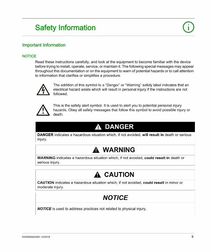
NOTICERead these instructions carefully, and look at the equipment to become familiar with the device before trying to install, operate, service, or maintain it. The following special messages may appear throughout this documentation or on the equipment to warn of potential hazards or to call attention to information that clarifies or simplifies a procedure.
EIO0000003281 12/2018 9

PLEASE NOTEElectrical equipment should be installed, operated, serviced, and maintained only by qualified personnel. No responsibility is assumed by Schneider Electric for any consequences arising out of the use of this material.A qualified person is one who has skills and knowledge related to the construction and operation of electrical equipment and its installation, and has received safety training to recognize and avoid the hazards involved.
10 EIO0000003281 12/2018

About the Book
At a Glance
Document ScopeThis guide describes how to use the EcoStruxure Machine Expert - Basic software to configure, program, and commission applications for supported logic controllers.
Validity NoteThe information in this manual is applicable only for EcoStruxure Machine Expert - Basic products.
This document has been updated for the release of EcoStruxureTM Machine Expert - Basic V1.0.The technical characteristics of the devices described in the present document also appear online. To access the information online:
The characteristics that are presented in the present document should be the same as those characteristics that appear online. In line with our policy of constant improvement, we may revise content over time to improve clarity and accuracy. If you see a difference between the document and online information, use the online information as your reference.
Step Action1 Go to the Schneider Electric home page www.schneider-electric.com.2 In the Search box type the reference of a product or the name of a product range.
Do not include blank spaces in the reference or product range. To get information on grouping similar modules, use asterisks (*).
3 If you entered a reference, go to the Product Datasheets search results and click on the reference that interests you.If you entered the name of a product range, go to the Product Ranges search results and click on the product range that interests you.
4 If more than one reference appears in the Products search results, click on the reference that interests you.
5 Depending on the size of your screen, you may need to scroll down to see the data sheet.6 To save or print a data sheet as a .pdf file, click Download XXX product datasheet.
EIO0000003281 12/2018 11

Related Documents
Title of Documentation Reference NumberEcoStruxure Machine Expert - Basic Generic Functions - Library Guide
EIO0000003289 (ENG)EIO0000003290 (FRE)EIO0000003291 (GER)EIO0000003292 (SPA)EIO0000003293 (ITA)EIO0000003294 (CHS)EIO0000003295 (POR)EIO0000003296 (TUR)
Modicon M221 Logic Controller Advanced Functions - Library Guide EIO0000003305 (ENG)EIO0000003306 (FRE)EIO0000003307 (GER)EIO0000003308 (SPA)EIO0000003309 (ITA)EIO0000003310 (CHS)EIO0000003311 (POR)EIO0000003312 (TUR)
Modicon M221 Logic Controller - Programming Guide EIO0000003297 (ENG)EIO0000003298 (FRE)EIO0000003299 (GER)EIO0000003300 (SPA)EIO0000003301 (ITA)EIO0000003302 (CHS)EIO0000003303 (POR)EIO0000003304 (TUR)
Modicon M221 Logic Controller - Hardware Guide EIO0000003313 (ENG)EIO0000003314 (FRE)EIO0000003315 (GER)EIO0000003316 (SPA)EIO0000003317 (ITA)EIO0000003318 (CHS)EIO0000003319 (POR)EIO0000003320 (TUR)
Modicon TMC2 Cartridge - Programming Guide EIO0000003329 (ENG)EIO0000003330 (FRE)EIO0000003331 (GER)EIO0000003332 (SPA)EIO0000003333 (ITA)EIO0000003334 (CHS)EIO0000003335 (POR)EIO0000003336 (TUR)
12 EIO0000003281 12/2018

Modicon TMC2 Cartridge - Hardware Guide EIO0000003337 (ENG)EIO0000003338 (FRE)EIO0000003339 (GER)EIO0000003340 (SPA)EIO0000003341 (ITA)EIO0000003342 (CHS)EIO0000003343 (POR)EIO0000003344 (TUR)
Modicon TM3 Expansion Modules Configuration - Programming Guide
EIO0000003345 (ENG)EIO0000003346 (FRE)EIO0000003347 (GER)EIO0000003348 (SPA)EIO0000003349 (ITA)EIO0000003350 (CHS)EIO0000003351 (POR)EIO0000003352 (TUR)
Modicon TM3 Digital I/O Modules - Hardware Guide EIO0000003125 (ENG)EIO0000003126 (FRE)EIO0000003127 (GER)EIO0000003128 (SPA)EIO0000003129 (ITA)EIO0000003130 (CHS)EIO0000003424 (POR)EIO0000003425 (TUR)
Modicon TM3 Analog I/O Modules - Hardware Guide EIO0000003131 (ENG)EIO0000003132 (FRE)EIO0000003133 (GER)EIO0000003134 (SPA)EIO0000003135 (ITA)EIO0000003136 (CHS)EIO0000003426 (POR)EIO0000003427 (TUR)
Modicon TM3 Expert Modules - Hardware Guide EIO0000003137 (ENG)EIO0000003138 (FRE)EIO0000003139 (GER)EIO0000003140 (SPA)EIO0000003141 (ITA)EIO0000003142 (CHS)EIO0000003428 (POR)EIO0000003429 (TUR)
Title of Documentation Reference Number
EIO0000003281 12/2018 13

You can download these technical publications and other technical information from our website at https://www.schneider-electric.com/en/download
Modicon TM3 Safety Modules - Hardware Guide EIO0000003353 (ENG)EIO0000003354 (FRE)EIO0000003355 (GER)EIO0000003356 (SPA)EIO0000003357 (ITA)EIO0000003358 (CHS)EIO0000003359 (POR)EIO0000003360 (TUR)
Modicon TM3 Transmitter and Receiver Modules - Hardware Guide EIO0000003143 (ENG)EIO0000003144 (FRE)EIO0000003145 (GER)EIO0000003146 (SPA)EIO0000003147 (ITA)EIO0000003148 (CHS)EIO0000003430 (POR)EIO0000003431 (TUR)
Modicon TM2 Expansion Modules Configuration - Programming Guide
EIO0000003432 (ENG)EIO0000003433 (FRE)EIO0000003434 (GER)EIO0000003435 (SPA)EIO0000003436 (ITA)EIO0000003437 (CHS)
Modicon TM2 Digital I/O Modules - Hardware Guide EIO0000000028 (ENG)EIO0000000029 (FRE)EIO0000000030 (GER)EIO0000000031 (SPA)EIO0000000032 (ITA)EIO0000000033 (CHS)
Modicon TM2 Analog I/O Modules - Hardware Guide EIO0000000034 (ENG)EIO0000000035 (FRE)EIO0000000036 (GER)EIO0000000037 (SPA)EIO0000000038 (ITA)EIO0000000039 (CHS)
SR2MOD02 and SR2MOD03 Wireless Modem - User Guide EIO0000001575 (ENG)
Title of Documentation Reference Number
14 EIO0000003281 12/2018

Product Related Information
1 For additional information, refer to NEMA ICS 1.1 (latest edition), "Safety Guidelines for the Application, Installation, and Maintenance of Solid State Control" and to NEMA ICS 7.1 (latest edition), "Safety Standards for Construction and Guide for Selection, Installation and Operation of Adjustable-Speed Drive Systems" or their equivalent governing your particular location.
WARNINGLOSS OF CONTROL The designer of any control scheme must consider the potential failure modes of control paths
and, for certain critical control functions, provide a means to achieve a safe state during and after a path failure. Examples of critical control functions are emergency stop and overtravel stop, power outage and restart.
Separate or redundant control paths must be provided for critical control functions. System control paths may include communication links. Consideration must be given to the
implications of unanticipated transmission delays or failures of the link. Observe all accident prevention regulations and local safety guidelines.1 Each implementation of this equipment must be individually and thoroughly tested for proper
operation before being placed into service.Failure to follow these instructions can result in death, serious injury, or equipment damage.
WARNINGUNINTENDED EQUIPMENT OPERATION Only use software approved by Schneider Electric for use with this equipment. Update your application program every time you change the physical hardware configuration.Failure to follow these instructions can result in death, serious injury, or equipment damage.
EIO0000003281 12/2018 15

Terminology Derived from Standards The technical terms, terminology, symbols and the corresponding descriptions in this manual, or that appear in or on the products themselves, are generally derived from the terms or definitions of international standards.In the area of functional safety systems, drives and general automation, this may include, but is not limited to, terms such as safety, safety function, safe state, fault, fault reset, malfunction, failure, error, error message, dangerous, etc.Among others, these standards include:
Standard DescriptionIEC 61131-2:2007 Programmable controllers, part 2: Equipment requirements and tests.ISO 13849-1:2015 Safety of machinery: Safety related parts of control systems.
General principles for design.EN 61496-1:2013 Safety of machinery: Electro-sensitive protective equipment.
Part 1: General requirements and tests.ISO 12100:2010 Safety of machinery - General principles for design - Risk assessment and risk
reductionEN 60204-1:2006 Safety of machinery - Electrical equipment of machines - Part 1: General
requirementsISO 14119:2013 Safety of machinery - Interlocking devices associated with guards - Principles
for design and selectionISO 13850:2015 Safety of machinery - Emergency stop - Principles for designIEC 62061:2005 Safety of machinery - Functional safety of safety-related electrical, electronic,
and electronic programmable control systemsIEC 61508-1:2010 Functional safety of electrical/electronic/programmable electronic safety-related
systems: General requirements.IEC 61508-2:2010 Functional safety of electrical/electronic/programmable electronic safety-related
systems: Requirements for electrical/electronic/programmable electronic safety-related systems.
IEC 61508-3:2010 Functional safety of electrical/electronic/programmable electronic safety-related systems: Software requirements.
IEC 61784-3:2016 Industrial communication networks - Profiles - Part 3: Functional safety fieldbuses - General rules and profile definitions.
2006/42/EC Machinery Directive2014/30/EU Electromagnetic Compatibility Directive2014/35/EU Low Voltage Directive
16 EIO0000003281 12/2018
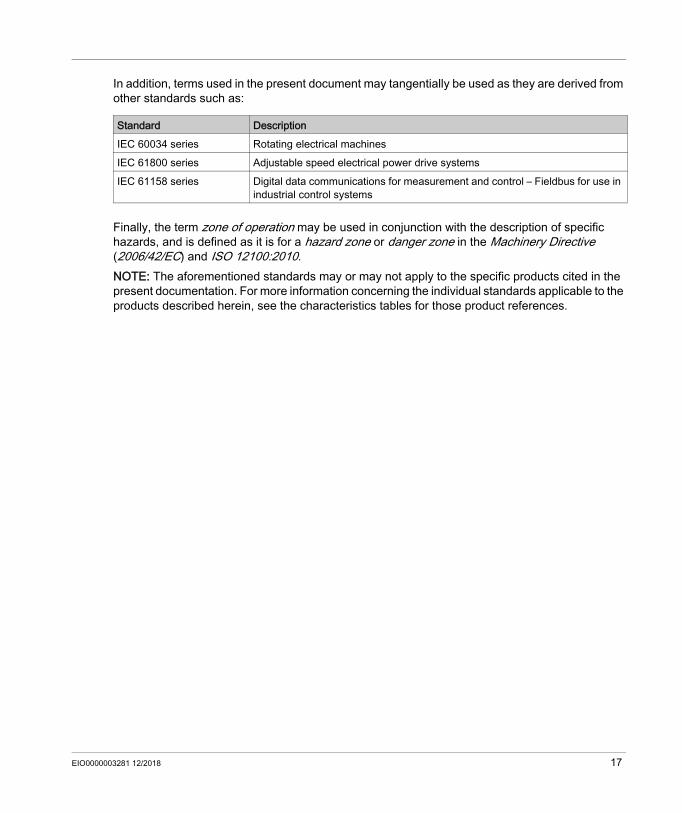
In addition, terms used in the present document may tangentially be used as they are derived from other standards such as:
Finally, the term zone of operation may be used in conjunction with the description of specific hazards, and is defined as it is for a hazard zone or danger zone in the Machinery Directive (2006/42/EC) and ISO 12100:2010.NOTE: The aforementioned standards may or may not apply to the specific products cited in the present documentation. For more information concerning the individual standards applicable to the products described herein, see the characteristics tables for those product references.
Standard DescriptionIEC 60034 series Rotating electrical machinesIEC 61800 series Adjustable speed electrical power drive systemsIEC 61158 series Digital data communications for measurement and control – Fieldbus for use in
industrial control systems
EIO0000003281 12/2018 17

18 EIO0000003281 12/2018

EcoStruxure Machine Expert - BasicGetting Started with EcoStruxure Machine Expert - BasicEIO0000003281 12/2018
Getting Started with EcoStruxure Machine Expert - Basic
Part IGetting Started with EcoStruxure Machine Expert - Basic
EIO0000003281 12/2018 19

Getting Started with EcoStruxure Machine Expert - Basic
20 EIO0000003281 12/2018

EcoStruxure Machine Expert - BasicIntroduction to EcoStruxure Machine Expert - BasicEIO0000003281 12/2018
Introduction to EcoStruxure Machine Expert - Basic
Chapter 1Introduction to EcoStruxure Machine Expert - Basic
What Is in This Chapter?This chapter contains the following sections:
Section Topic Page1.1 System Requirements and Supported Devices 221.2 EcoStruxure Machine Expert - Basic User Interface Basics 271.3 The Start Menu 32
EIO0000003281 12/2018 21

Introduction to EcoStruxure Machine Expert - Basic
System Requirements and Supported Devices
Section 1.1System Requirements and Supported Devices
What Is in This Section?This section contains the following topics:
Topic PageSystem Requirements 23Supported Devices 24Supported Programming Languages 26
22 EIO0000003281 12/2018

Introduction to EcoStruxure Machine Expert - Basic
System Requirements
OverviewThe minimum system requirements for the PC on which EcoStruxure Machine Expert - Basic software is installed are: Intel Core 2 Duo processor or greater 1 GB RAM Display resolution 1280 x 768 pixels or greater The 32- or 64-bit version of one of the following operating systems: Microsoft Windows 7 Microsoft Windows 8 Microsoft Windows 8.1 Microsoft Windows 10
EIO0000003281 12/2018 23

Introduction to EcoStruxure Machine Expert - Basic
Supported Devices
M221 Logic ControllersFor more information about the M221 logic controller configuration, refer to the following programming and hardware guides:
TM3 Expansion ModulesFor more information about module configuration, refer to the following programming and hardware guides of each expansion module type:
TM2 Expansion ModulesFor more information about module configuration, refer to the programming and hardware guides of each expansion module type:
TMC2 CartridgesFor more information about cartridge configuration, refer to the following programming and hardware guides:
Logic Controller Type Hardware Guide Programming GuideM221 Logic Controllers Modicon M221 Logic Controller
Hardware GuideModicon M221 Logic Controller Programming Guide
Expansion Module Type Hardware Guide Programming GuideTM3 Digital I/O Expansion Modules TM3 Digital I/O Expansion Modules
Hardware GuideTM3 Expansion Modules Programming Guide
TM3 Analog I/O Expansion Modules TM3 Analog Modules Hardware GuideTM3 Expert I/O Expansion Modules TM3 Expert I/O Modules Hardware
GuideTM3 Safety Modules TM3 Safety Modules Hardware GuideTM3 Transmitter and Receiver Modules TM3 Transmitter and Receiver
Modules Hardware Guide
Expansion Module Type Hardware Guide Programming GuideTM2 Digital I/O Modules TM2 Digital I/O Modules Hardware
GuideTM2 Expansion Modules Programming Guide
TM2 Analog I/O Modules TM2 Analog I/O Modules Hardware Guide
Cartridge Type Hardware Guide Programming GuideTMC2 Cartridges TMC2 Cartridges Hardware Guide TMC2 Cartridges Programming
Guide
24 EIO0000003281 12/2018

Introduction to EcoStruxure Machine Expert - Basic
TMH2GDB Remote Graphic DisplayFor information about the Remote Graphic Display installation, compatibility, configuration, and operation, refer to the following guide:
Display Type User Guide Remote Graphic Display TMH2GDB Remote Graphic Display User Guide
EIO0000003281 12/2018 25
Introduction to EcoStruxure Machine Expert - Basic
Supported Programming Languages
OverviewA programmable logic controller reads inputs, writes outputs, and solves logic based on a control program. Creating a control program for a logic controller consists of writing a series of instructions in one of the supported programming languages.EcoStruxure Machine Expert - Basic supports the following IEC-61131-3 programming languages: Ladder Diagram language Instruction List language Grafcet (List) Grafcet (SFC)
26 EIO0000003281 12/2018

Introduction to EcoStruxure Machine Expert - Basic
EcoStruxure Machine Expert - Basic User Interface Basics
Section 1.2EcoStruxure Machine Expert - Basic User Interface Basics
What Is in This Section?This section contains the following topics:
Topic PageCreating Projects With EcoStruxure Machine Expert - Basic 28Developing Programs With EcoStruxure Machine Expert - Basic 29Navigating Within EcoStruxure Machine Expert - Basic 30Operating Modes 31
EIO0000003281 12/2018 27

Introduction to EcoStruxure Machine Expert - Basic
Creating Projects With EcoStruxure Machine Expert - Basic
OverviewEcoStruxure Machine Expert - Basic is a graphical programming tool designed to make it easy to configure, develop, and commission programs for logic controllers.
Some Essential TerminologyEcoStruxure Machine Expert - Basic uses the following terms: Project: An EcoStruxure Machine Expert - Basic project contains details about the developer
and purpose of the project, the configuration of the logic controller and associated expansion modules targeted by the project, the source code of a program, symbols, comments, documentation, and all other related information.
Application: Contains all parts of the project that are downloaded to the logic controller, including the compiled program, hardware configuration information, and non-program data (project properties, symbols, and comments).
Program: The compiled source code that runs on the logic controller. POU (program organization unit): The reusable object that contains a variable declaration and
a set of instructions used in a program.
28 EIO0000003281 12/2018
Introduction to EcoStruxure Machine Expert - Basic
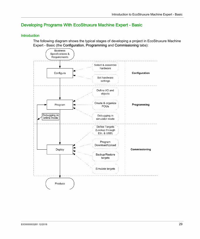
Developing Programs With EcoStruxure Machine Expert - Basic
IntroductionThe following diagram shows the typical stages of developing a project in EcoStruxure Machine Expert - Basic (the Configuration, Programming and Commissioning tabs):
EIO0000003281 12/2018 29

Introduction to EcoStruxure Machine Expert - Basic
Navigating Within EcoStruxure Machine Expert - Basic
Module AreasOnce you have selected a project to work with, EcoStruxure Machine Expert - Basic displays the main window.At the top of the main window, a toolbar (see page 45) contains icons that allow you to perform common tasks, including opening the Start Menu.Next to the toolbar, the status bar (see page 47) displays informational messages about the current state of the connection to the logic controller.Below this, the main window is divided into a number of modules. Each module controls a different stage of the development cycle, and is accessible by clicking a tab at the top of the module area. To develop an application, work your way through the modules from left to right: Properties (see page 53)
Set up the project properties Configuration (see page 59)
Define the hardware configuration of the logic controller and associated expansion modules Programming (see page 63)
Develop your program in one of the supported programming languages Display (see Modicon M221, Logic Controller, Programming Guide)
Build an operator interface for the TMH2GDB Remote Graphic Display module Commissioning (see page 239)
Manage the connection between EcoStruxure Machine Expert - Basic and the logic controller, upload/download applications, test, and commission the application.
30 EIO0000003281 12/2018
Introduction to EcoStruxure Machine Expert - Basic
Operating Modes
IntroductionThe operating modes provide control to develop, debug, monitor, and modify the application when the controller is connected or not connected to EcoStruxure Machine Expert - Basic.EcoStruxure Machine Expert - Basic can operate in the following modes: Offline mode Online mode Simulator mode
Offline ModeEcoStruxure Machine Expert - Basic operates in offline mode when no physical connection to a logic controller has been established.In offline mode, you configure EcoStruxure Machine Expert - Basic to match the hardware components you are targeting, then develop your application.
Online ModeEcoStruxure Machine Expert - Basic operates in online mode when a logic controller is physically connected to the PC.In online mode, you can proceed to download your application to the logic controller (downloading and uploading application is not possible in the simulator mode because the application is directly saved in the simulated logic controller). EcoStruxure Machine Expert - Basic then synchronizes the application in the PC memory with the version stored in the logic controller, allowing you to debug, monitor, and modify the application.You can modify certain elements of a program in online mode. For example, you can add or delete rungs, or modify the values of certain function block parameters.NOTE: Online program modifications are subjected to the predefined configuration. See Memory Management. Refer to Debugging in Online Mode (see page 225) for more information.
Simulator ModeEcoStruxure Machine Expert - Basic operates in simulator mode when a connection has been established with a simulated logic controller. In simulator mode, no physical connection to a logic controller is established; instead EcoStruxure Machine Expert - Basic simulates a connection to a logic controller and the expansion modules to run and test the program.For more information, refer to EcoStruxure Machine Expert - Basic Simulator (see page 264).
EIO0000003281 12/2018 31

Introduction to EcoStruxure Machine Expert - Basic
The Start Menu
Section 1.3The Start Menu
What Is in This Section?This section contains the following topics:
Topic PageIntroduction to the Start Menu 33Registering the EcoStruxure Machine Expert - Basic Software 34Open Project Window 35Project Templates Window 38Help Window 39
32 EIO0000003281 12/2018

Introduction to EcoStruxure Machine Expert - Basic
Introduction to the Start Menu
OverviewThe Start Menu has the following items: New Project
To create a new project. Open Project (see page 35)
To open an existing project. Templates (see page 38)
To create a new project using an example project as a template. Help (see page 39)
To display the online help, related documents, training materials, and tutorials. About
To display information about EcoStruxure Machine Expert - Basic. Exit
To exit from EcoStruxure Machine Expert - Basic.
EIO0000003281 12/2018 33

Introduction to EcoStruxure Machine Expert - Basic
Registering the EcoStruxure Machine Expert - Basic Software
OverviewYou can use the EcoStruxure Machine Expert - Basic software for 30 days before you are required to register the software. When you register, you receive an authorization code to use the software.Registering your EcoStruxure Machine Expert - Basic software entitles you to receive technical support and software updates.
RegisteringTo register your EcoStruxure Machine Expert - Basic software:
Step Action1 In the Start Menu, click About → Register now.2 Follow the instructions on the Registration Wizard. Click the Help button for more details.
34 EIO0000003281 12/2018

Introduction to EcoStruxure Machine Expert - Basic
Open Project Window
OverviewUse the Projects window to create a new EcoStruxure Machine Expert - Basic project or to open an existing EcoStruxure Machine Expert - Basic, TwidoSoft, or TwidoSuite project to work with.The right-hand area of the Projects window contains links to additional useful information.
EIO0000003281 12/2018 35

Introduction to EcoStruxure Machine Expert - Basic
Opening an EcoStruxure Machine Expert - Basic Project FileFollow these steps to open a project file:
Step Action1 Click Open Project on the Start Menu.2 Do one of the following:
Click a recent project in the Recent projects list. Click Open an existing project and select an existing EcoStruxure Machine Expert - Basic project
file (*.smbp) or a sample project file (*.smbe).3 Case 1
If a window asking you to enter the password appears, it means that the project is password-protected:1. Type the encryption password.2. Click Apply3. To modify the project:
a. Click on the Properties tab.Result: A window asking you to enter the password appears.
b. Type the modification password.c. Click Apply.
Result: The project file opens and the Configuration tab is displayed.Case 2If an error icon is displayed on the Properties tab, it means that the project that you want to open was password-protected in a previous version of EcoStruxure Machine Expert - Basic with View and Download selected:1. Click Properties tab → Project Protection.
2. Click on the Properties tab.3. Type a password to encrypt the project.
You must encrypt the project to be allowed to save it.4. Click Apply.Case 3If the Error window appears, it means that the project that you want to open was password-protected in a previous version of EcoStruxure Machine Expert - Basic with Download only selected:1. Click OK
Result: The Properties tab is displayed.2. Click Project Protection.
3. Click , then enter the project password.4. If you want to remove the project protection, select Inactive and click Apply.
If you want to keep the project protection, type the encryption password, select View and Download. Result: As the View and Download is the default mode, the check box disappears.
5. Click Apply.
36 EIO0000003281 12/2018
Introduction to EcoStruxure Machine Expert - Basic
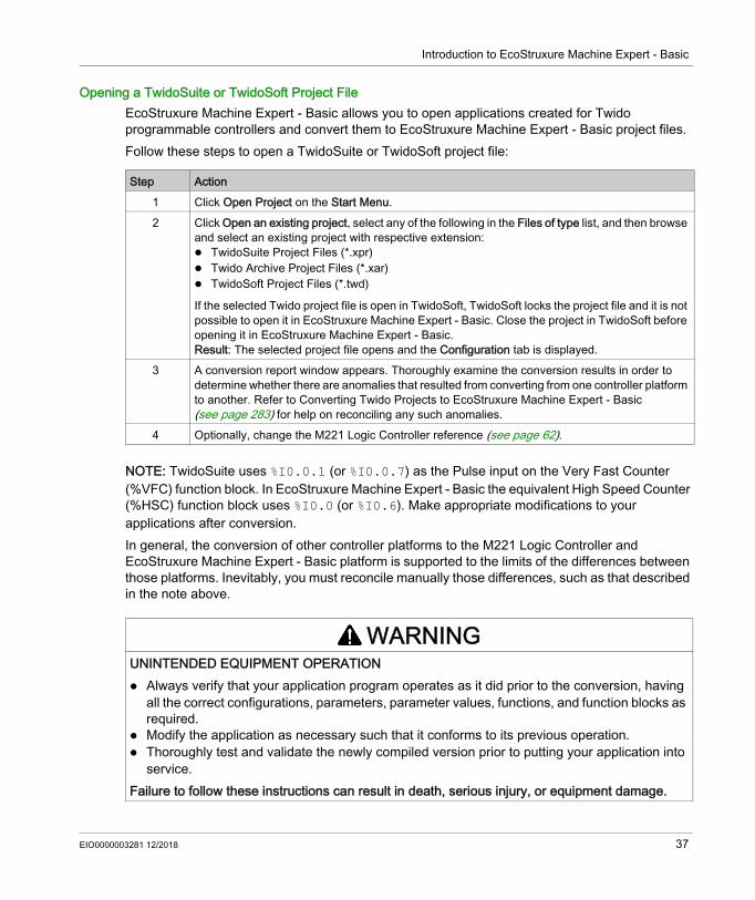
Opening a TwidoSuite or TwidoSoft Project FileEcoStruxure Machine Expert - Basic allows you to open applications created for Twido programmable controllers and convert them to EcoStruxure Machine Expert - Basic project files.Follow these steps to open a TwidoSuite or TwidoSoft project file:
NOTE: TwidoSuite uses %I0.0.1 (or %I0.0.7) as the Pulse input on the Very Fast Counter (%VFC) function block. In EcoStruxure Machine Expert - Basic the equivalent High Speed Counter (%HSC) function block uses %I0.0 (or %I0.6). Make appropriate modifications to your applications after conversion.In general, the conversion of other controller platforms to the M221 Logic Controller and EcoStruxure Machine Expert - Basic platform is supported to the limits of the differences between those platforms. Inevitably, you must reconcile manually those differences, such as that described in the note above.
Step Action1 Click Open Project on the Start Menu.2 Click Open an existing project, select any of the following in the Files of type list, and then browse
and select an existing project with respective extension: TwidoSuite Project Files (*.xpr) Twido Archive Project Files (*.xar) TwidoSoft Project Files (*.twd)
If the selected Twido project file is open in TwidoSoft, TwidoSoft locks the project file and it is not possible to open it in EcoStruxure Machine Expert - Basic. Close the project in TwidoSoft before opening it in EcoStruxure Machine Expert - Basic. Result: The selected project file opens and the Configuration tab is displayed.
3 A conversion report window appears. Thoroughly examine the conversion results in order to determine whether there are anomalies that resulted from converting from one controller platform to another. Refer to Converting Twido Projects to EcoStruxure Machine Expert - Basic (see page 283) for help on reconciling any such anomalies.
4 Optionally, change the M221 Logic Controller reference (see page 62).
WARNINGUNINTENDED EQUIPMENT OPERATION Always verify that your application program operates as it did prior to the conversion, having
all the correct configurations, parameters, parameter values, functions, and function blocks as required.
Modify the application as necessary such that it conforms to its previous operation. Thoroughly test and validate the newly compiled version prior to putting your application into
service.Failure to follow these instructions can result in death, serious injury, or equipment damage.
EIO0000003281 12/2018 37

Introduction to EcoStruxure Machine Expert - Basic
Project Templates Window
OverviewYou can use example projects to form the basis of new EcoStruxure Machine Expert - Basic projects.
Opening a Project TemplateFollow these steps to create a new project based on a project template:
Step Action1 Select Templates on the Start Menu.2 Use the Search in templates text field located in the upper right-hand corner of the window to
search for projects. As you type, EcoStruxure Machine Expert - Basic searches in the project name, the description of the project available in the lower of the window, and the project properties. A list of matching projects appears as you type. Select a project template file (*.smbe) in the Projects list and click Open Template.Result: A new project is created as a copy of the selected template.For projects that have a help file linked to the project template, click the Open Associated Help button for an Open associated help to be opened. If available, the option is highlighted below the Projects list.
NOTE: EcoStruxure Machine Expert - Basic also provides a Vijeo-Designer application file and a System User Guide for some example projects. Read the description of the selected project in the Description area to know whether these files are provided with your project or not. If these files are provided, click Open associated folder to browse through the project template files (*.smbe) and Vijeo-Designer application files (*.vdz) in Windows Explorer.
38 EIO0000003281 12/2018

Introduction to EcoStruxure Machine Expert - Basic
Help Window
OverviewThis window contains links to additional EcoStruxure Machine Expert - Basic resources: The EcoStruxure Machine Expert - Basic online help system Related PDF documents, such as System User Guides (SUGs), training materials, Instruction
Sheets, and descriptions of example applications E-Learning training materials Tutorials Information for converting Twido applications for use with EcoStruxure Machine Expert - Basic.
EIO0000003281 12/2018 39

Introduction to EcoStruxure Machine Expert - Basic
40 EIO0000003281 12/2018

EcoStruxure Machine Expert - BasicDeveloping EcoStruxure Machine Expert - Basic ApplicationsEIO0000003281 12/2018
Developing EcoStruxure Machine Expert - Basic Applications
Part IIDeveloping EcoStruxure Machine Expert - Basic Applications
What Is in This Part?This part contains the following chapters:
Chapter Chapter Name Page2 The EcoStruxure Machine Expert - Basic Window 433 Properties 534 Configuration 595 Programming 636 Commissioning 2397 Simulator 2638 Saving Projects and Closing EcoStruxure Machine Expert - Basic 277
EIO0000003281 12/2018 41

Developing EcoStruxure Machine Expert - Basic Applications
42 EIO0000003281 12/2018

EcoStruxure Machine Expert - BasicEcoStruxure Machine Expert - BasicEIO0000003281 12/2018
The EcoStruxure Machine Expert - Basic Window
Chapter 2The EcoStruxure Machine Expert - Basic Window
EIO0000003281 12/2018 43
EcoStruxure Machine Expert - Basic
Overview of the EcoStruxure Machine Expert - Basic Window
Section 2.1Overview of the EcoStruxure Machine Expert - Basic Window
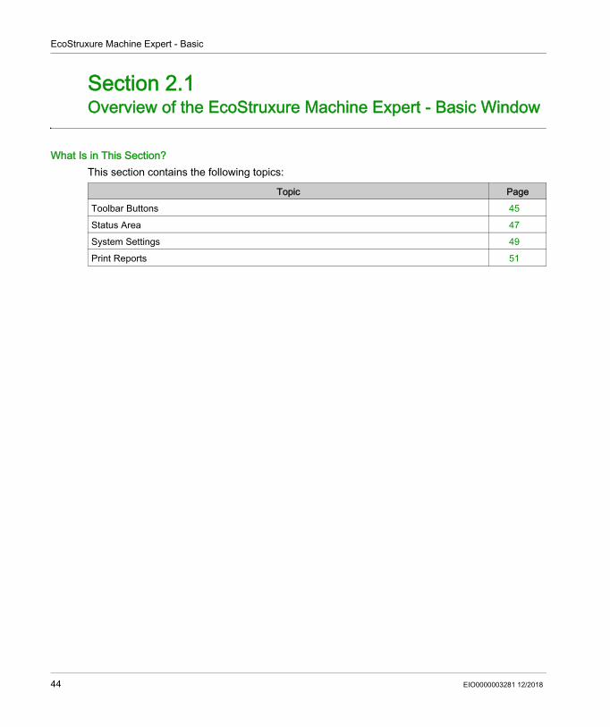
What Is in This Section?This section contains the following topics:
Topic PageToolbar Buttons 45Status Area 47System Settings 49Print Reports 51
44 EIO0000003281 12/2018

EcoStruxure Machine Expert - Basic
Toolbar Buttons
IntroductionThe toolbar appears at the top of the EcoStruxure Machine Expert - Basic window to provide an access to frequently-used functions.
ToolbarThe toolbar has the following buttons:
Icon DescriptionOpen the Start Menu.
Create a new project (CTRL+N)
Open an existing project (CTRL+O)
Save the current project (CTRL+S). Click the down arrow to display a menu with additional save options.
Print a report (CTRL+P). Click the down arrow to select the report to print (see page 51) or to configure the report content and format (see page 52).
Cut (CTRL+X)
Copy (CTRL+C)
Paste (CTRL+V)
Undo (CTRL+Z). Click once to undo the most recent action in the program editor.Click the down arrow and select an action from the list to undo all actions up to and including the selected action. You can undo up to 10 actions.Redo (CTRL+Y). Click once to cancel the most recent Undo action.Click the down arrow and select an action from the list to redo all actions up to and including the selected action.You can redo up to 10 actions.Display the System Settings (see page 49) window.
EIO0000003281 12/2018 45
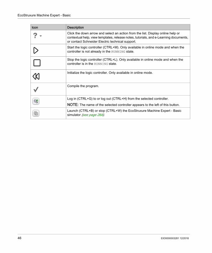
EcoStruxure Machine Expert - Basic
Click the down arrow and select an action from the list. Display online help or contextual help, view templates, release notes, tutorials, and e-Learning documents, or contact Schneider Electric technical support.Start the logic controller (CTRL+M). Only available in online mode and when the controller is not already in the RUNNING state.
Stop the logic controller (CTRL+L). Only available in online mode and when the controller is in the RUNNING state.
Initialize the logic controller. Only available in online mode.
Compile the program.
Log in (CTRL+G) to or log out (CTRL+H) from the selected controller.
NOTE: The name of the selected controller appears to the left of this button.
Launch (CTRL+B) or stop (CTRL+W) the EcoStruxure Machine Expert - Basic simulator (see page 264).
Icon Description
46 EIO0000003281 12/2018

EcoStruxure Machine Expert - Basic
Status Area
OverviewThe status area at the top of the main window displays information on the present system status:
1 Program status:Indicates whether the program has errors detected or not.
2 Connection status:Indicates the connection status between EcoStruxure Machine Expert - Basic and either the logic controller or the simulated logic controller.
3 Controller status:Indicates the present state of the logic controller (RUNNING, STOPPED, HALTED, and so on).
4 Scan time:Indicates the last scan time.
5 Controller last error detected:Indicates the most recent error detected. Information is extracted from the system bits and system words if the logic controller is in STOPPED or HALTED state.
Status Area MessagesThe following messages can appear in the status area:
Message Type Possible Message DescriptionProgram status [No errors] No errors detected in the program.
[Program advisory(ies) detected]
Program is incomplete.
[Program error(s) detected] No program or the program contains error(s).Connection status [Not connected] EcoStruxure Machine Expert - Basic is running in offline mode.
[Online] EcoStruxure Machine Expert - Basic is running in online mode.
EIO0000003281 12/2018 47
EcoStruxure Machine Expert - Basic
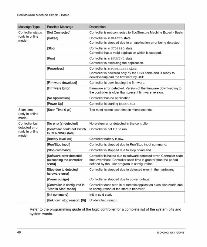
Refer to the programming guide of the logic controller for a complete list of the system bits and system words.
Controller status(only in online mode)
[Not Connected] Controller is not connected to EcoStruxure Machine Expert - Basic.[Halted] Controller is in HALTED state.
Controller is stopped due to an application error being detected.[Stop] Controller is in STOPPED state.
Controller has a valid application which is stopped.[Run] Controller is in RUNNING state.
Controller is executing the application.[Powerless] Controller is in POWERLESS state.
Controller is powered only by the USB cable and is ready to download/upload the firmware by USB.
[Firmware download] Controller is downloading the firmware.[Firmware Error] Firmware error detected. Version of the firmware downloading to
the controller is older than present firmware version.[No Application] Controller has no application.[Power Up] Controller is starting (BOOTING).
Scan time(only in online mode)
[Scan Time 0 µs] The most recent scan time in microseconds.
Controller last detected error(only in online mode)
[No error(s) detected] No system error detected in the controller.[Controller could not switch to RUNNING state]
Controller is not OK to run.
[Battery level low] Controller battery is low.[Run/Stop input] Controller is stopped due to Run/Stop input command.[Stop command] Controller is stopped due to stop command.[Software error detected (exceeding the controller scan)]
Controller is halted due to software detected error. Controller scan time overshoot. Controller scan time is greater than the period defined by the user program in configuration.
[Stop due to detected hardware error]
Controller is stopped due to detected error in the hardware.
[Power outage] Controller is stopped due to power outage.[Controller is configured in 'Start in Stop' mode]
Controller does start in automatic application execution mode due to configuration of the startup behavior.
[Init command] Init in cold start.[Unknown stop reason: {0}] Unidentified reason.
Message Type Possible Message Description
48 EIO0000003281 12/2018

EcoStruxure Machine Expert - Basic
System Settings
OverviewThis window allows you to set the language of the EcoStruxure Machine Expert - Basic software, customize the Ladder editor, and choose the default logic controller that appears on the Configuration tab when you create a new project.
Changing the User Interface LanguageFollow these steps to change the user interface language:
Changing Shortcuts for HelpFollow these steps to change the keyboard shortcut to access contextual or general help:
Customizing the Ladder EditorFollow these steps to customize the Ladder editor:
Step Action1 Choose System Settings → General on the System Settings window.2 Select the language to use in the Language list.
The default language is English.3 Click Apply and close the System Settings window.4 Close and restart EcoStruxure Machine Expert - Basic to view the user interface in the new
language.
Step Action1 Choose System Settings → General on the System Settings window.2 Select F1 or Shift + F1 for contextual help.
The shortcut for General help is automatically updated.
Step Action1 Choose System Settings → Ladder Editor on the System Settings window.2 Choose the Grid lines style for the Ladder editor.
Dots (default) Dashed Lines Lines
3 Set the Number of columns (11...30) for the cells in the Ladder editor.The default value of number of cells is 11.For more information, refer to Programming Principles for Ladder Diagrams (see page 170).
EIO0000003281 12/2018 49

EcoStruxure Machine Expert - Basic
Choosing a Default Logic ControllerFollow these steps to choose a default logic controller:
4 Under Tool Selection Conservation, select: Keep selected tool (default): After selecting and placing a graphic element in a rung, the most
recently selected graphic element remains selected. This allows you to place the same element in a rung again without reselecting it. Press the ESC key or right-click an empty cell
in the rung to select the pointer tool .
Reset to pointer: After selecting and placing a contact or a coil in a rung, the pointer tool is automatically selected.To insert the same contact or coil element again, select it in the toolbar.
5 Choose the Shortcuts and toolbar style setting for the Ladder Editor: Ecostruxure Machine Expert - Basic set (default) Asian set 1 Asian set 2 European set American set
For the selected style, the table displays a list of keyboard shortcuts for each of the toolbar buttons displayed.
6 Click Apply and close the System Settings window to view the changes in the Ladder editor.
Step Action
Step Action1 Choose System Settings → Configuration on the System Settings window.2 Click Preferred controller and choose a default logic controller from the list.3 Click Apply and close the System Settings window.4 Close and restart EcoStruxure Machine Expert - Basic to view the new default logic controller in
the Configuration tab when a new project is created.
50 EIO0000003281 12/2018
EcoStruxure Machine Expert - Basic
Print Reports
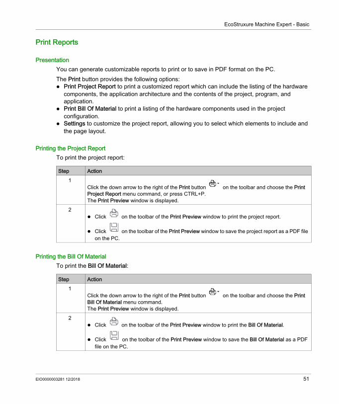
PresentationYou can generate customizable reports to print or to save in PDF format on the PC.The Print button provides the following options: Print Project Report to print a customized report which can include the listing of the hardware
components, the application architecture and the contents of the project, program, and application.
Print Bill Of Material to print a listing of the hardware components used in the project configuration.
Settings to customize the project report, allowing you to select which elements to include and the page layout.
Printing the Project ReportTo print the project report:
Printing the Bill Of MaterialTo print the Bill Of Material:
Step Action1
Click the down arrow to the right of the Print button on the toolbar and choose the Print Project Report menu command, or press CTRL+P.The Print Preview window is displayed.
2 Click on the toolbar of the Print Preview window to print the project report.
Click on the toolbar of the Print Preview window to save the project report as a PDF file on the PC.
Step Action1
Click the down arrow to the right of the Print button on the toolbar and choose the Print Bill Of Material menu command.The Print Preview window is displayed.
2 Click on the toolbar of the Print Preview window to print the Bill Of Material.
Click on the toolbar of the Print Preview window to save the Bill Of Material as a PDF file on the PC.
EIO0000003281 12/2018 51

EcoStruxure Machine Expert - Basic
Customizing the Project ReportTo select which items to include in the project report and configure its layout:
Step Action1
Click the down arrow to the right of the Print button on the toolbar and choose the Settings menu command.The Settings window is displayed.
2 Click the Report node to configure the format settings of the report (paper size, margins, and orientation).
3 Select the items to include in the project report: Description is the project description as in the Project Information window. Bill Of Material is the listing of the hardware components used in the project configuration. Hardware Configuration is a listing of the hardware devices used in the configuration: IO Bus is a list of the I/O expansion modules used. Cartridges is a list of the cartridges used.
Software Configuration is to include/exclude the following items: Constant words is a list of constant word (%KW) objects used in the project. Network objects is a list of objects used to communicate with Ethernet/IP or Modbus TCP
devices. Software Objects lists the software objects used in the program, such as timers and counters. PTO objects lists PTO function blocks used in the program. Communication Objects lists the communication objects used in the program.
Program is to include/exclude the following items: Behavior is the settings configured in the Behavior window. Memory consumption is the amount of controller memory used by the application, program,
and associated user data. Application architecture is the settings configured in the Master Task and Periodic Task
windows. POU is a listing of the POUs used in the program.
Display is a report section containing information about the Remote Graphic Display: General properties is the general parameters that appear on the Display tab. There is an
option to print the password in your report. Alarm View displays a list of triggered alarms. Pages is a list of operator interface pages created on the Display tab.
Symbols is a list of all symbols or of the symbols used in the project. Cross-reference is a table containing the used addresses, objects, rungs, and the line of code
in which they are used. Animation table is a table containing the objects added to animation tables in the project.
4 Close the window.
52 EIO0000003281 12/2018

EcoStruxure Machine Expert - BasicProperties EIO0000003281 12/2018
Properties
Chapter 3Properties
EIO0000003281 12/2018 53
Properties
Overview of the Properties Window
Section 3.1Overview of the Properties Window
What Is in This Section?This section contains the following topics:
Topic PageThe Properties Window 55Project Properties 56
54 EIO0000003281 12/2018
Properties
The Properties Window
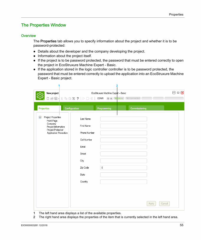
OverviewThe Properties tab allows you to specify information about the project and whether it is to be password-protected: Details about the developer and the company developing the project. Information about the project itself. If the project is to be password protected, the password that must be entered correctly to open
the project in EcoStruxure Machine Expert - Basic. If the application stored in the logic controller controller is to be password protected, the
password that must be entered correctly to upload the application into an EcoStruxure Machine Expert - Basic project.
1 The left hand area displays a list of the available properties.2 The right hand area displays the properties of the item that is currently selected in the left hand area.
EIO0000003281 12/2018 55

Properties
Project Properties
OverviewUse the Properties window to provide details about the user of EcoStruxure Machine Expert - Basic, the company developing the application, and the project. In this window, you can also password protect the project file and the application when stored in the logic controller.
Specifying Application Developer PropertiesTo specify the application developer properties:
NOTE: This information appears in the Windows Explorer properties window when you right-click on an EcoStruxure Machine Expert - Basic project file.
Specifying Company PropertiesTo specify the company properties:
Specifying Project InformationTo specify project information:
Step Action1 Display the Properties tab and click Project Properties → Front Page.2 Complete the information.3 Click Apply.
Step Action1 Display the Properties tab and click Project Properties → Company.2 Complete the information.
To upload the company logo image, click Change then browse to select the file to upload. Click Removed to delete the current image.
3 Click Apply.
Step Action1 Display the Properties tab and click Project Properties → Project Information.2 Complete the information.
To upload an image, such as a photograph or CAD image of the instrumented machine, click Change then browse to select the file to upload. Click Removed to delete the current image.
3 Click Apply.
56 EIO0000003281 12/2018

Properties
Password-Protecting a ProjectIt is possible to encrypt and password-protect a project file.If a project is encrypted, you are prompted for the encryption password whenever you try to open the project.If the project is protected against modifications, by default you can only view the project. To modify the project, type the modification password.Follow these steps to encrypt and password-protect a project file:
If you want to prevent a program from being modified, create a controller image and then restore it to controller (see page 255).
Removing Password Protection from a ProjectFollow these steps to remove password protection from a project:
Step Action1 Display the Properties tab and click Project Properties → Project Protection.2 Select the Active option. Required items of information are marked with an asterisk (*).3 Type the password and type it again as confirmation to encrypt the project.4 Optionally, type a password and the confirmation to protect the project from modifications.5 Click Apply.
Step Action1 Display the Properties tab and click Project Properties → Project Protection.2 Select the Inactive option.3 Click Apply.
NOTE: If prompted to provide the modification password, type the modification password and click Apply.
EIO0000003281 12/2018 57

Properties
Password Protecting an ApplicationEcoStruxure Machine Expert - Basic allows an application stored in the logic controller to be protected with a password. This password controls uploading of the application from the logic controller into an EcoStruxure Machine Expert - Basic project.Follow these steps to password-protect an application:
Removing Password Protection from an ApplicationFollow these steps to remove password protection from an application:
Step Action1 Display the Properties tab and click Project Properties → Application Protection.2 Choose the level of application protection:
Select Active and leave Password blank to disable application upload from the logic controller to the PC.
Select Active and type the same password in the Password and Confirmation fields to password protect the application. You must then enter this password when prompted before uploading the application from the logic controller to the PC.
3 Click Apply.
Step Action1 Display the Properties tab and click Project Properties → Application Protection.2 Select the Inactive option.3 Click Apply.
NOTE: If prompted to provide the current password before the Inactive option applies successfully, type the password and click Apply.
58 EIO0000003281 12/2018

EcoStruxure Machine Expert - BasicConfigurationEIO0000003281 12/2018
Configuration
Chapter 4Configuration
EIO0000003281 12/2018 59
Configuration
Overview of the Configuration Window
Section 4.1Overview of the Configuration Window
What Is in This Section?This section contains the following topics:
Topic PageOverview of the Configuration Window 61Building a Configuration 62
60 EIO0000003281 12/2018

Configuration
Overview of the Configuration Window
IntroductionUse the Configuration window to recreate the hardware configuration of the logic controller and expansion modules to be targeted by the program.
1 The Hardware Tree - a structured view of the hardware configuration.2 The configuration - a logic controller and expansion modules.3 Catalog references of the supported logic controller and expansion module hardware components. To add
a component to the hardware configuration, drag and drop it onto the configuration.4 The properties of the component selected in the configuration, or the properties of the selected item in the
Hardware Tree.
EIO0000003281 12/2018 61
Configuration
Building a Configuration
Replacing the Default Logic ControllerWhen you create a new EcoStruxure Machine Expert - Basic project, a logic controller reference appears in the central area of the Configuration window.
NOTE: The default controller reference is specified in the System Settings window (see page 49).
Configuring the Logic ControllerUse the Configuration window to configure the logic controller.Refer to the Programming Guide of the logic controller used in the configuration for details.
Configuring Expansion ModulesUse the Configuration window to add and configure expansion modules. Refer to the Programming Guide of the expansion module used in the configuration for details.
Step Action1 Click the Configuration tab.2 Expand the logic controller category in the catalog area on the right, if it is not already displayed.3 Select a logic controller reference. A short description of the physical properties of the logic
controller appear in the Device description area.4 Drag the logic controller reference over the image of the existing logic controller in the central
area of the window and drop it. 5 Click Yes when prompted to confirm replacing the logic controller reference.
62 EIO0000003281 12/2018

EcoStruxure Machine Expert - BasicProgrammingEIO0000003281 12/2018
Programming
Chapter 5Programming
What Is in This Chapter?This chapter contains the following sections:
Section Topic Page5.1 Overview of the Programming Workspace 645.2 Special Functions 665.3 Configuring Program Behavior and Tasks 765.4 Managing POUs 855.5 User-Defined Functions 995.6 User-Defined Function Blocks 1075.7 Master Task 1155.8 Strings 1195.9 Periodic Task 125
5.10 Event Task 1295.11 Using Tools 1365.12 Ladder Language Programming 1675.13 Instruction List Programming 1905.14 Grafcet (List) Programming 2025.15 Grafcet (SFC) Programming 2105.16 Debugging in Online Mode 225
EIO0000003281 12/2018 63

Programming
Overview of the Programming Workspace
Section 5.1Overview of the Programming Workspace
Overview of the Programming Workspace
OverviewThe Programming tab is split into 3 main areas:
64 EIO0000003281 12/2018

Programming
1 The Programming Tree allows you to select the properties of the program and its objects, and functions, as well as a number of tools which you can use to monitor and debug the program.
2 The upper central area is the programming workspace where you enter the source code of your program.3 The lower central area allows you to view and configure the properties of the item selected in the
programming workspace or the Programming Tree.
EIO0000003281 12/2018 65
Programming
Special Functions
Section 5.2Special Functions
What Is in This Section?This section contains the following topics:
Topic PageObjects 67Symbolic Addressing 68Memory Allocation 70Ladder/List Reversibility 71
66 EIO0000003281 12/2018

Programming
Objects
OverviewIn EcoStruxure Machine Expert - Basic, the term object is used to represent an area of logic controller memory reserved for use by an application. Objects can be: Simple software variables, such as memory bits and words Addresses of digital or analog inputs and outputs Controller-internal variables, such as system words and system bits Predefined system functions or function blocks, such as timers and counters.Controller memory is either pre-allocated for certain object types, or automatically allocated when an application is downloaded to the logic controller.Objects can only be addressed by a program once memory has been allocated. Objects are addressed using the prefix %. For example, %MW12 is the address of a memory word, %Q0.3 is the address of an embedded digital output, and %TM0 is the address of a Timer function block.
EIO0000003281 12/2018 67

Programming
Symbolic Addressing
IntroductionEcoStruxure Machine Expert - Basic supports the symbolic addressing of language objects; that is, the indirect addressing of objects by name. Using symbols allows for quick examination and analysis of program logic, and greatly simplifies the development and testing of an application.
ExampleFor example, WASH_END is a symbol that could be used to identify an instance of a Timer function block representing the end of a wash cycle. Recalling the purpose of this name is easier than trying to remember the role of a program address such as %TM3.
Defining a Symbol in the Properties WindowTo define a symbol in the properties window:
Step Action1 Select the Tools tab in the left-hand area of the Programming window.2 Select the type of object with which to define a symbol, for example I/O objects → Digital inputs,
to display the properties of digital inputs.The properties window of the object type appears in the lower central area of the Programming window.
3 Double-click in the Symbol column of the properties table and type the symbol to define for a particular item, for example Input_1 for the input %I0.2
4 Click Apply.
68 EIO0000003281 12/2018
Programming
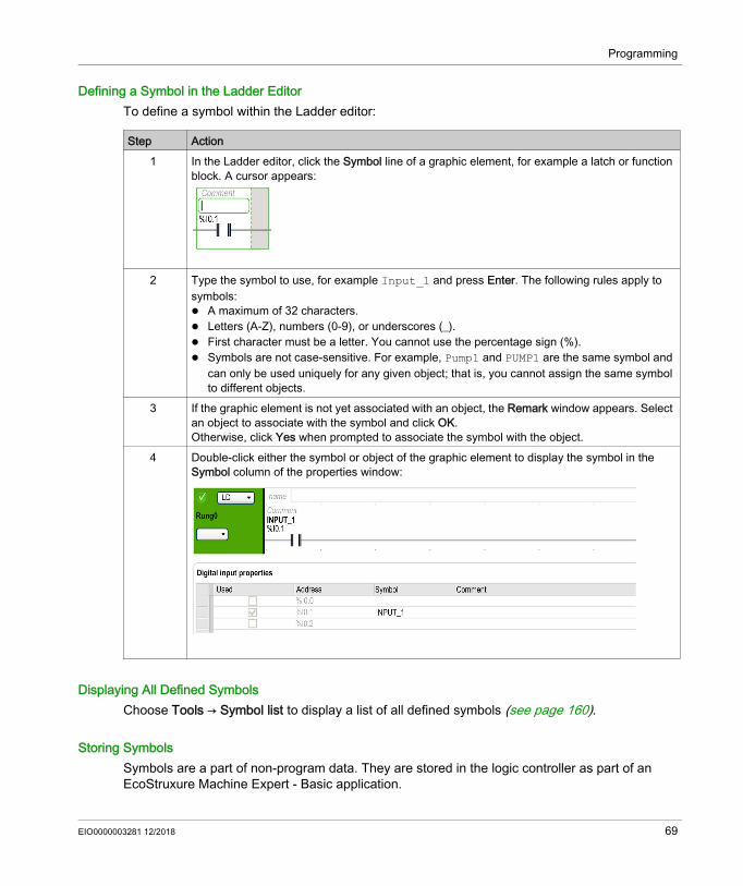
Defining a Symbol in the Ladder EditorTo define a symbol within the Ladder editor:
Displaying All Defined SymbolsChoose Tools → Symbol list to display a list of all defined symbols (see page 160).
Storing SymbolsSymbols are a part of non-program data. They are stored in the logic controller as part of an EcoStruxure Machine Expert - Basic application.
Step Action1 In the Ladder editor, click the Symbol line of a graphic element, for example a latch or function
block. A cursor appears:
2 Type the symbol to use, for example Input_1 and press Enter. The following rules apply to symbols: A maximum of 32 characters. Letters (A-Z), numbers (0-9), or underscores (_). First character must be a letter. You cannot use the percentage sign (%). Symbols are not case-sensitive. For example, Pump1 and PUMP1 are the same symbol and
can only be used uniquely for any given object; that is, you cannot assign the same symbol to different objects.
3 If the graphic element is not yet associated with an object, the Remark window appears. Select an object to associate with the symbol and click OK.Otherwise, click Yes when prompted to associate the symbol with the object.
4 Double-click either the symbol or object of the graphic element to display the symbol in the Symbol column of the properties window:
EIO0000003281 12/2018 69
Programming
Memory Allocation
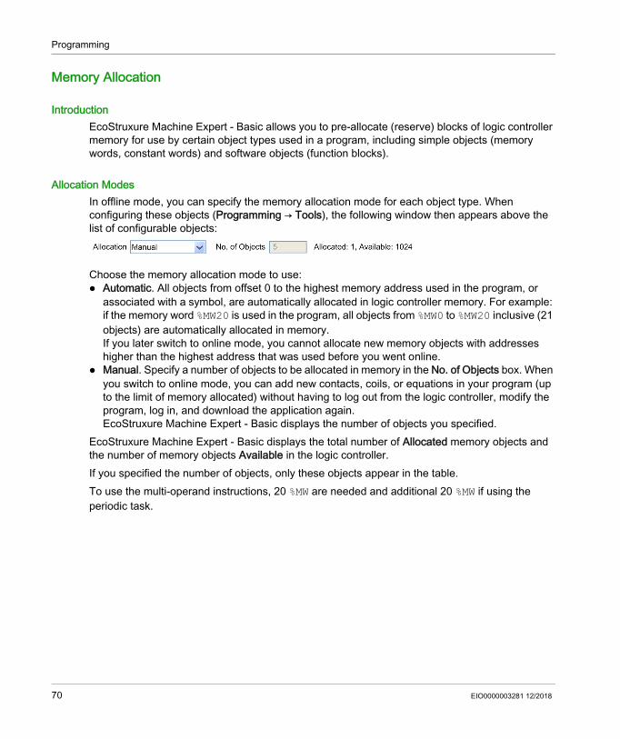
IntroductionEcoStruxure Machine Expert - Basic allows you to pre-allocate (reserve) blocks of logic controller memory for use by certain object types used in a program, including simple objects (memory words, constant words) and software objects (function blocks).
Allocation ModesIn offline mode, you can specify the memory allocation mode for each object type. When configuring these objects (Programming → Tools), the following window then appears above the list of configurable objects:
Choose the memory allocation mode to use: Automatic. All objects from offset 0 to the highest memory address used in the program, or
associated with a symbol, are automatically allocated in logic controller memory. For example: if the memory word %MW20 is used in the program, all objects from %MW0 to %MW20 inclusive (21 objects) are automatically allocated in memory.If you later switch to online mode, you cannot allocate new memory objects with addresses higher than the highest address that was used before you went online.
Manual. Specify a number of objects to be allocated in memory in the No. of Objects box. When you switch to online mode, you can add new contacts, coils, or equations in your program (up to the limit of memory allocated) without having to log out from the logic controller, modify the program, log in, and download the application again.EcoStruxure Machine Expert - Basic displays the number of objects you specified.
EcoStruxure Machine Expert - Basic displays the total number of Allocated memory objects and the number of memory objects Available in the logic controller.If you specified the number of objects, only these objects appear in the table.To use the multi-operand instructions, 20 %MW are needed and additional 20 %MW if using the periodic task.
70 EIO0000003281 12/2018

Programming
Ladder/List Reversibility
IntroductionEcoStruxure Machine Expert - Basic supports conversion of rungs from Ladder Diagram to Instruction List and from Instruction List back to Ladder Diagram. This is called program reversibility.In EcoStruxure Machine Expert - Basic, you can toggle rungs between programming languages at any time as required. You can therefore display a program with some rungs in Ladder Diagram and other rungs in Instruction List.NOTE: You cannot convert Ladder and Instruction List programs to Grafcet (SFC), or Grafcet (SFC) programs to Ladder or Instruction List, or Grafcet (IL) to Grafcet (SFC).
Understanding ReversibilityA key to understanding program reversibility is examining the relationship between a Ladder Diagram rung and the associated Instruction List rung: Ladder Diagram rung: A collection of Ladder Diagram instructions that constitute a logical
expression. List sequence: A collection of Instruction List programming instructions that correspond to the
Ladder Diagram instructions and represents the same logical expression. The following illustration displays a common Ladder Diagram rung and its equivalent program logic expressed as a sequence of Instruction List instructions.
Equivalent Instruction List instruction:
EIO0000003281 12/2018 71
Programming
A program is always stored internally as Instruction List instructions, regardless of whether it is originally written in the Ladder Diagram or Instruction List language. EcoStruxure Machine Expert - Basic takes advantage of the program structure similarities between the 2 languages and uses this internal Instruction List image of the program to display it either as an Instruction List program, or graphically as a Ladder Diagram.
Instructions Required for Reversibility The structure of a reversible function block in Instruction List language requires the use of the following instructions: BLK marks the block start, and defines the beginning of the rung and the start of the input portion
to the block. OUT_BLK marks the beginning of the output portion of the block. END_BLK marks the end of the block and the rung.
The use of these reversible function block instructions is not mandatory for a properly functioning Instruction List program.
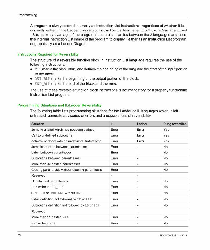
Programming Situations and IL/Ladder ReversibilityThe following table lists programming situations for the Ladder or IL languages which, if left untreated, generate advisories or errors and a possible loss of reversibility.
Situation IL Ladder Rung reversibleJump to a label which has not been defined Error Error YesCall to undefined subroutine Error Error YesActivate or deactivate an undefined Grafcet step Error Error YesJump instruction between parentheses Error - NoLabel between parentheses Error - NoSubroutine between parentheses Error - NoMore than 32 nested parentheses Error - NoClosing parenthesis without opening parenthesis Error - NoReserved - - -Unbalanced parentheses Error - NoBLK without END_BLK Error - No
OUT_BLK or END_BLK without BLK Error - No
Label definition not followed by LD or BLK Error - No
Subroutine definition not followed by LD or BLK Error - No
Reserved - - -More than 11 nested MPS Error - No
MRD without MPS Error - No
72 EIO0000003281 12/2018

Programming
MPP without MPS Error - No
Use Grafcet instruction in POST Error Error Yes
Grafcet definition not followed by BLK or LD Error - No
Unbalanced stack operations Error - NoReserved - - -Duplicate label Error Error Only LD->ILDuplicate Subroutine Error Error Only LD->ILDuplicate Grafcet step Error Error Only LD->ILReserved - - -Duplicate POST Error Error Only LD->IL
Nested FB Error - NoOUT_BLK between BLK and END_BLK Error - No
BLK not followed by LD Error - No
LD of FB output not in OUT_BLK Error - No
FB outputs used outside their respective FB structure Error - NoFB outputs repeated or out of order Error - NoFB inputs not in BLK before OUT_BLK Error - No
FB inputs used outside their respective FB structure Error - NoFB inputs repeated or out of order Error - NoLabel declared in BLK Error - No
Subroutines declared in BLK Error - No
Grafcet steps declared in BLK Error - No
Attempted LD of a non FB output in OUT_BLK Error - No
FB output used between BLK and END_BLK Error - No
Nested subroutines Error Error NoSubroutine call between MPS and MPP Error Error No
Subroutine call between parentheses Error - NoReserved - -First instruction of program not a rung delimiter Error - NoJump instruction between MPS and MPP Error Error No
Rung contains syntax error Error - NoReserved - - -Reserved - - -
Situation IL Ladder Rung reversible
EIO0000003281 12/2018 73
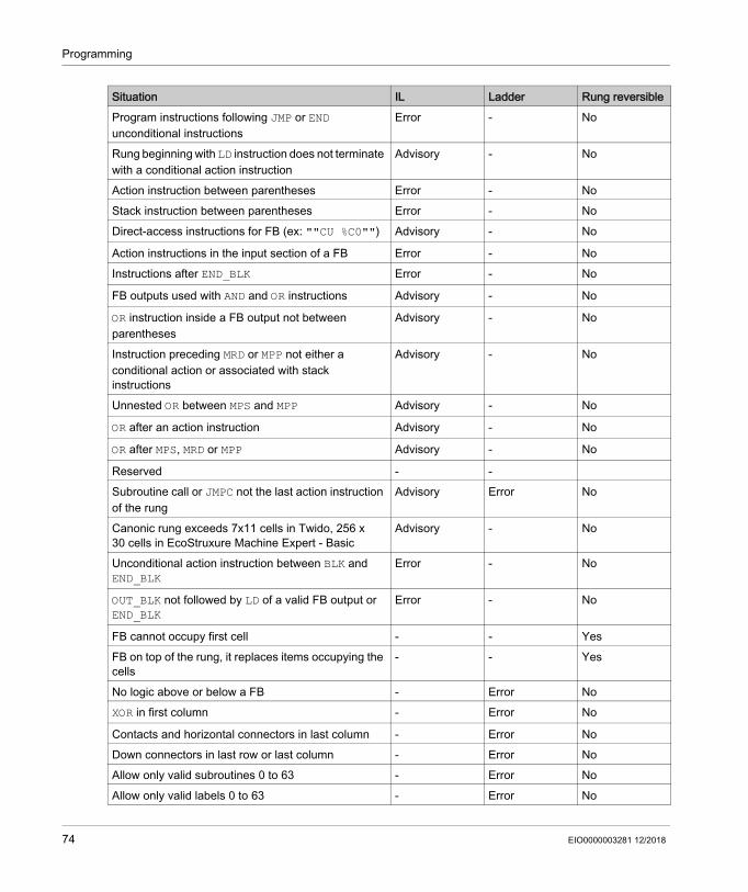
Programming
Program instructions following JMP or END unconditional instructions
Error - No
Rung beginning with LD instruction does not terminate with a conditional action instruction
Advisory - No
Action instruction between parentheses Error - NoStack instruction between parentheses Error - NoDirect-access instructions for FB (ex: ""CU %C0"") Advisory - No
Action instructions in the input section of a FB Error - NoInstructions after END_BLK Error - No
FB outputs used with AND and OR instructions Advisory - No
OR instruction inside a FB output not between parentheses
Advisory - No
Instruction preceding MRD or MPP not either a conditional action or associated with stack instructions
Advisory - No
Unnested OR between MPS and MPP Advisory - No
OR after an action instruction Advisory - No
OR after MPS, MRD or MPP Advisory - No
Reserved - -Subroutine call or JMPC not the last action instruction of the rung
Advisory Error No
Canonic rung exceeds 7x11 cells in Twido, 256 x 30 cells in EcoStruxure Machine Expert - Basic
Advisory - No
Unconditional action instruction between BLK and END_BLK
Error - No
OUT_BLK not followed by LD of a valid FB output or END_BLK
Error - No
FB cannot occupy first cell - - YesFB on top of the rung, it replaces items occupying the cells
- - Yes
No logic above or below a FB - Error NoXOR in first column - Error No
Contacts and horizontal connectors in last column - Error NoDown connectors in last row or last column - Error NoAllow only valid subroutines 0 to 63 - Error NoAllow only valid labels 0 to 63 - Error No
Situation IL Ladder Rung reversible
74 EIO0000003281 12/2018
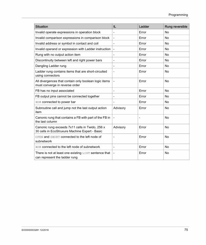
Programming
Invalid operate expressions in operation block - Error NoInvalid comparison expressions in comparison block - Error NoInvalid address or symbol in contact and coil - Error NoInvalid operand or expression with Ladder instruction - Error NoRung with no output action item - Error NoDiscontinuity between left and right power bars - Error NoDangling Ladder rung - Error NoLadder rung contains items that are short-circuited using connectors
- Error No
All divergences that contain only boolean logic items must converge in reverse order
- Error No
FB has no input associated - Error NoFB output pins cannot be connected together - Error NoXOR connected to power bar - Error No
Subroutine call and jump not the last output action item
Advisory Error No
Canonic rung that contains a FB with part of the FB in the last column
- - No
Canonic rung exceeds 7x11 cells in Twido, 256 x 30 cells in EcoStruxure Machine Expert - Basic
Advisory Error No
OPEN and SHORT connected to the left node of subnetwork
- Error No
XOR connected to the left node of subnetwork - Error No
There is not at least one existing LIST sentence that can represent the ladder rung
- Error No
Situation IL Ladder Rung reversible
EIO0000003281 12/2018 75

Programming
Configuring Program Behavior and Tasks
Section 5.3Configuring Program Behavior and Tasks
What Is in This Section?This section contains the following topics:
Topic PageApplication Behavior 77Tasks and Scan Modes 82
76 EIO0000003281 12/2018

Programming
Application Behavior
OverviewYou can configure the following aspects of how the application interacts with the logic controller: Startup (see page 77) Watchdog (see page 79) Fallback behavior (see page 79) Functional levels (see page 80)
Configuring Application BehaviorFollow these steps to configure the application behavior:
StartupSpecify how the program behaves following a restart of the logic controller: Start In Previous State: The logic controller starts in the state that it was in before it was stopped. Start In Stop: The logic controller does not automatically start application execution. Start In Run (default): The logic controller automatically starts application execution given run
criteria, such as the presence and charge of a battery, are met. Unconditional Start In Run: The logic controller automatically starts application execution even
if the controller battery is absent or discharged.
Step Action1 Select the Tasks tab in the left-hand area of the Programming window.2 Select the Behavior item.
Result: The Behavior properties appear in the lower central area of the Programming window.3 Modify the properties as required.4 Click Apply to save the changes.
EIO0000003281 12/2018 77

Programming
When using the Start In Run feature, the controller will start executing program logic when power is applied to the equipment. It is essential to know in advance how automatic reactivation of the outputs will affect the process or machine being controlled. Configure the Run/Stop input to help control the Start In Run feature. In addition, the Run/Stop input is designed to give local control over remote RUN commands. If the possibility of a remote RUN command after the controller had been stopped locally by EcoStruxure Machine Expert - Basic would have unintended consequences, you must configure and wire the Run/Stop input to help control this situation.
WARNINGUNINTENDED MACHINE START-UP Confirm that the automatic reactivation of the outputs does not produce unintended
consequences before using the Start In Run feature. Use the Run/Stop input to help control the Start In Run feature and to help prevent the
unintentional start-up from a remote location. Verify the state of security of your machine or process environment before applying power to
the Run/Stop input or before issuing a Run command from a remote location.Failure to follow these instructions can result in death, serious injury, or equipment damage.
WARNINGUNINTENDED MACHINE OR PROCESS START-UP Verify the state of security of your machine or process environment before applying power to
the Run/Stop input. Use the Run/Stop input to help prevent the unintentional start-up from a remote location.Failure to follow these instructions can result in death, serious injury, or equipment damage.
78 EIO0000003281 12/2018

Programming
When using the Unconditional Start In Run feature, the controller will attempt to start executing program logic when power is applied to the equipment, independent of the reason the controller had previously stopped. This occurs even if there is no charge in the battery, or if the battery is not present. Therefore, the controller will start with all memory values re-initialized to zero or other predetermined default values. It is conceivable that if the controller attempts to restart, for example, after a short power outage, the values in memory at the time of the outage would be lost, and restarting the machine may have unintended consequences as there was no battery to maintain memory values. It is essential to know in advance how an unconditional start will affect the process or machine being controlled. Configure the Run/Stop input to help control the Unconditional Start In Run feature.
WatchdogA watchdog is a special timer used so that programs do not overrun their allocated scan time.The watchdog timer has a default value of 250 ms. Specify the duration of the watchdog scan task. The possible range is 10...500 ms.
Fallback BehaviorSpecify the fallback behavior to use when the logic controller enters the STOPPED or an exception state for any reason.Two fallback behaviors exist: Select Fallback values to set outputs to the fallback values defined in the configuration
properties of embedded logic controller and expansion module outputs. This is the default. Refer to the Programming Guide of the logic controller or expansion module for information on configuring fallback values for outputs.Individual fallback values cannot be defined for configured Status Alarm, PTO, and FREQGEN outputs. The fallback value for these objects is 0 and cannot be modified.
Select Maintain values to keep each output in the state it was when the logic controller entered the STOPPED or an exception state. In this mode, the fallback values configured for logic controller and expansion module outputs are ignored and, instead, are set to the last value assumed by the output.Maintain values behavior is not applied to fast outputs (HSC reflex outputs, PLS, PWM, PTO, and FREQGEN); the fallback value for these objects is 0.
WARNINGUNINTENDED MACHINE OPERATION Conduct a thorough risk analysis to determine the effects, under all conditions, of configuring
the controller with the Unconditional Start In Run feature. Use the Run/Stop input to help avoid an unwanted unconditional restart.Failure to follow these instructions can result in death, serious injury, or equipment damage.
EIO0000003281 12/2018 79
Programming
Functional LevelsYour system could include logic controllers with different firmware versions, and therefore with different capability levels. EcoStruxure Machine Expert - Basic supports functional level management to allow you to control the functional level of your application.When EcoStruxure Machine Expert - Basic connects to the logic controller, it reads the functional level of the: Logic controller firmware to authorize download of the EcoStruxure Machine Expert - Basic
application to the logic controller. The functional level selected for the application must be less than or equal to the maximum functional level supported by the logic controller. If this is not the case, a message tells you to either update the firmware, or to manually downgrade the functional level of the application (by selecting a level from the Functional Levels list, see below).
Application in the logic controller, to determine whether to authorize upload of the logic controller application to the PC running EcoStruxure Machine Expert - Basic. To authorize application upload, the functional level of the logic controller application must be less than or equal to the maximum functional level supported by the installed version of EcoStruxure Machine Expert - Basic. If this is not the case, you must upgrade EcoStruxure Machine Expert - Basic to the latest version before uploading.
The Commissioning window displays the functional levels of the EcoStruxure Machine Expert - Basic application and the application embedded in the connected logic controller.Select a level from the Functional levels list: Level 10.0: Authorizes indexed memory bits, 200 Grafcet step objects, symbols for variables
and parameters in user-defined function block. Level 6.2: Authorizes improvement of the password strategy. Level 6.1: Authorizes strings support in SMS function block. Level 6.0: Authorizes Modbus TCP IOScanner, user-defined functions, user-defined function
blocks, data logging on SD card, string management, structure ladder block elements, rising and falling edge functions.
Level 5.1: Authorizes security strategy modification. Level 5.0: Authorizes Modbus Serial IOScanner, Drive and RTC function blocks, multi-operand
instructions. Level 4.1: Authorizes online mode enhancements, support for a modem on SL2. Level 4.0: Authorizes support for sink transistor output controllers, Grafcet (SFC), Frequency
Generator, Retentive Timer, Memory Management, Remote Graphic display evolution. Level 3.3: Authorizes enhancements (PTO Motion Task, HSC evolution). Level 3.2: Authorizes enhancements to support Optional module feature, EtherNet/IP adapter,
and %SEND_RECV_SMS function block. Level 3.1: Authorizes enhancements (Unconditional Start In Run feature). Level 3.0: Authorizes enhancements (communications, modem, Remote Graphic Display) to
the previous level of software and hardware.
80 EIO0000003281 12/2018

Programming
Level 2.0: Authorizes any enhancements and corrections over the previous level software and firmware. For example, for Pulse Train Output (PTO) support, it would be necessary to select this functional level or greater.
Level 1.0: First release of the combination of the EcoStruxure Machine Expert - Basic software and the compatible firmware version(s).
NOTE: Each successive level includes all functionality of the preceding levels.
EIO0000003281 12/2018 81
Programming
Tasks and Scan Modes
OverviewEcoStruxure Machine Expert - Basic has the following scan modes for Master task: Normal mode
Continuous cyclic scanning mode (Freewheeling mode); a new scan starts immediately after the previous scan has completed.
Periodic modePeriodic cyclic scanning mode; a new scan starts only after the configured scan time of the previous scan has elapsed. Every scan is therefore the same duration.
EcoStruxure Machine Expert - Basic offers the following task types: Master task: Main task of the application.
Master task is controlled by continuous cyclic scanning (in normal scan mode) or by specifying the scan period of 1...150 ms (default 100 ms) in periodic scan mode.
Periodic task: A short duration subroutine processed periodically.Periodic tasks are configured by specifying the scan period of 1...255 ms (default 255 ms).
Event task: A very short duration subroutine to reduce the response time of the application.Event tasks are triggered by the physical inputs or the HSC function blocks. These events are associated with embedded digital inputs (%I0.2...%I0.5) (rising, falling or both edges) or with the high speed counters (%HSC0 and %HSC1) (when the count reaches the high speed counter threshold). You can configure 2 events for each HSC function block.
Tasks PrioritiesThis table summarizes the task types and their priorities:
Events PrioritiesRefer to Event Priorities and Queues (see page 132).
Task Type Scan Mode Triggering Condition Configurable Range
Maximum Number of Tasks
Priority
Master Normal Normal Not applicable 1 LowestPeriodic Software timer 1...150 ms1
Periodic Periodic Software timer 1...255 ms1 1 Higher than master task and lower than event tasks
Event Periodic Physical inputs %I0.2...%I0.5 4 Highest%HSC function blocks 2 events per
%HSC object1 The application must be configured with a functional level (see page 80) of at least Level 5.0 to be able to configure a minimum value of 1 ms. Otherwise, the minimum value is 2 ms.
82 EIO0000003281 12/2018

Programming
Master Task in Normal Scan ModeThis graphic shows the relationship between master task and periodic task execution when the master task is configured in normal scan mode:
NOTE: The master task sleep time is at least 30% of the total cycle time with a minimum of 1 millisecond.
Master Task in Periodic Scan ModeThis graphic shows the relationship between master task and periodic task when the master task is configured in periodic scan mode:
EIO0000003281 12/2018 83
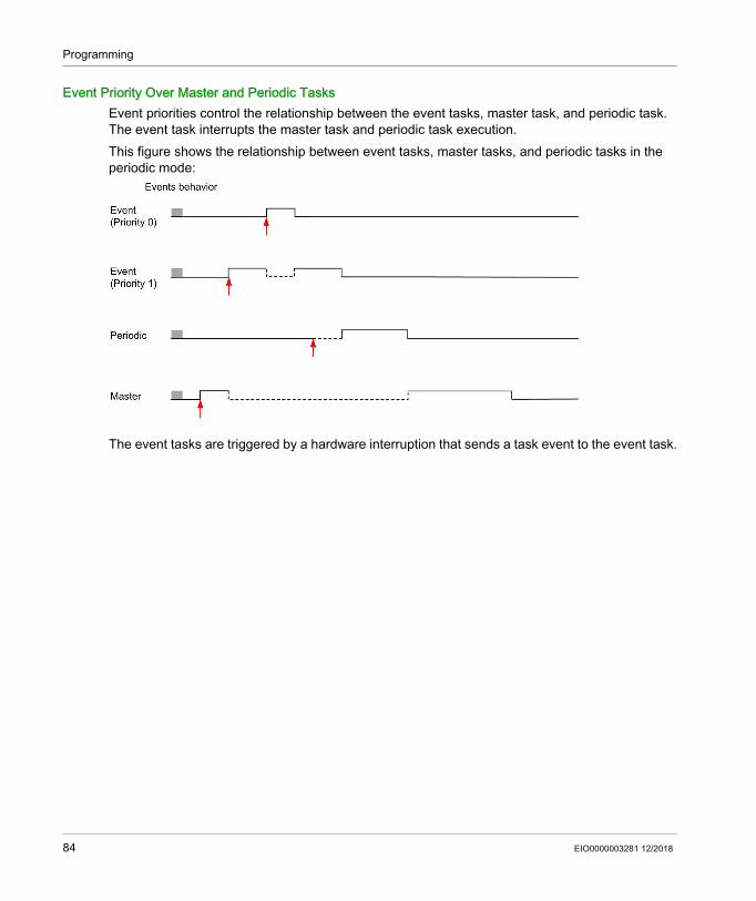
Programming
Event Priority Over Master and Periodic TasksEvent priorities control the relationship between the event tasks, master task, and periodic task. The event task interrupts the master task and periodic task execution.This figure shows the relationship between event tasks, master tasks, and periodic tasks in the periodic mode:
The event tasks are triggered by a hardware interruption that sends a task event to the event task.
84 EIO0000003281 12/2018
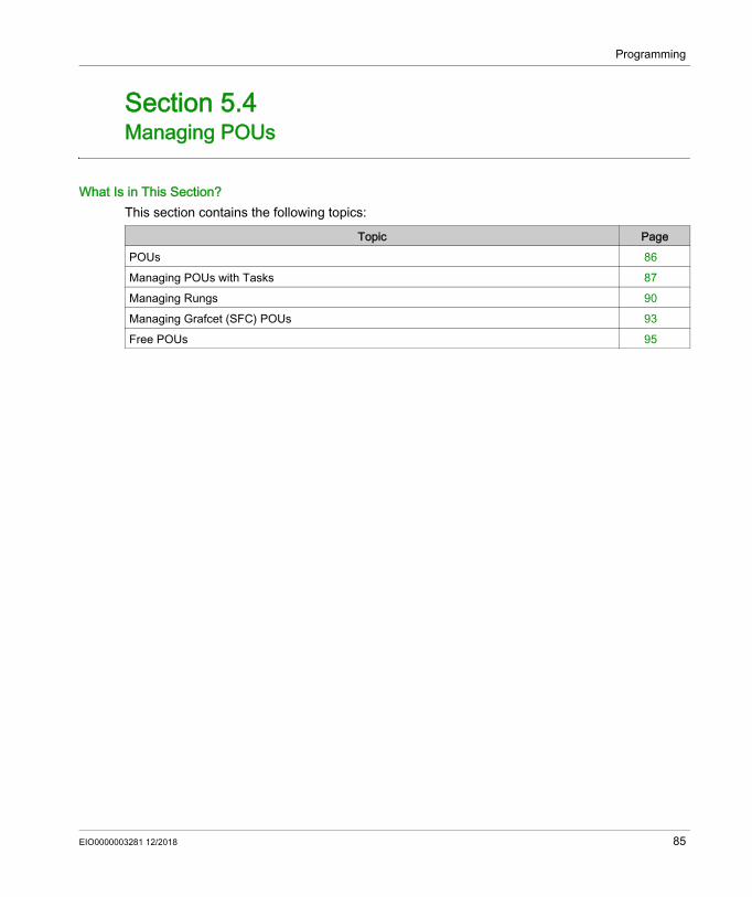
Programming
Managing POUs
Section 5.4Managing POUs
What Is in This Section?This section contains the following topics:
Topic PagePOUs 86Managing POUs with Tasks 87Managing Rungs 90Managing Grafcet (SFC) POUs 93Free POUs 95
EIO0000003281 12/2018 85
Programming
POUs
OverviewA Program Organization Unit (POU) is a reusable object used in a program. Each POU consists of a variable declaration and a set of instructions in the source code of a supported programming language.One POU always exists and is linked to the master task of the program. This POU is then called automatically whenever the program starts.You can create additional POUs containing other objects, for example, functions or function blocks. When first created, a POU can be either: associated with a task (see page 87), or a Free POU (see page 95). A Free POU is not associated with a specific task or event. A Free
POU can, for example, contain library functions that are maintained independently of the main program. Free POUs are called from within programs as either subroutines or jumps. A periodic task (see page 126) is a subroutine that is implemented as a Free POU.
86 EIO0000003281 12/2018

Programming
Managing POUs with Tasks
Adding a New POU Associated with a Task
Inserting a New POU
Copying and Pasting Existing POUs Associated with a Task
Step Action1 Select the Tasks tab in the left-hand area of the Programming window.2 Add a new POU by one of the following methods:
Right-click the Master Task and choose Add POU from the contextual menu that appears.
Select the Master Task and click (Add POU) on the toolbar at the top of the Tasks tab.
Result: A new POU is added to the program structure immediately below the default/last POU in the Master Task. The default name is n - New POU, where n is an integer incremented each time a POU is created.
3 To reposition a POU in the Master Task, select a POU and click the UP or DOWN button on the toolbar at the top of the Tasks tab to move the selected POU up or down in the program structure.
Step Action1 Select the Tasks tab in the left-hand area of the Programming window.2 Select an existing POU above which to insert the POU.3 Right-click the selected POU and choose Insert POU from the contextual menu that appears.4 To reposition a POU in the Master Task, select a POU and click the UP or DOWN button on the
toolbar at the top of the Tasks tab to move the selected POU up or down in the program structure.
Step Action1 Select the Tasks tab in the left-hand area of the Programming window.2 Select one or multiple POUs:
Select an existing POU in the Master Task. Press and hold the CTRL key and select each POU in the Master Task.
3 Right-click one of the selected POU in the Master Task and choose Copy POU from the contextual menu that appears.
4 Right-click the Master Task and choose Paste POU from the contextual menu that appears.Result: One or multiple POUs are added to the program structure immediately below the selected POU in the Master Task with the same name as the copied POU.
EIO0000003281 12/2018 87
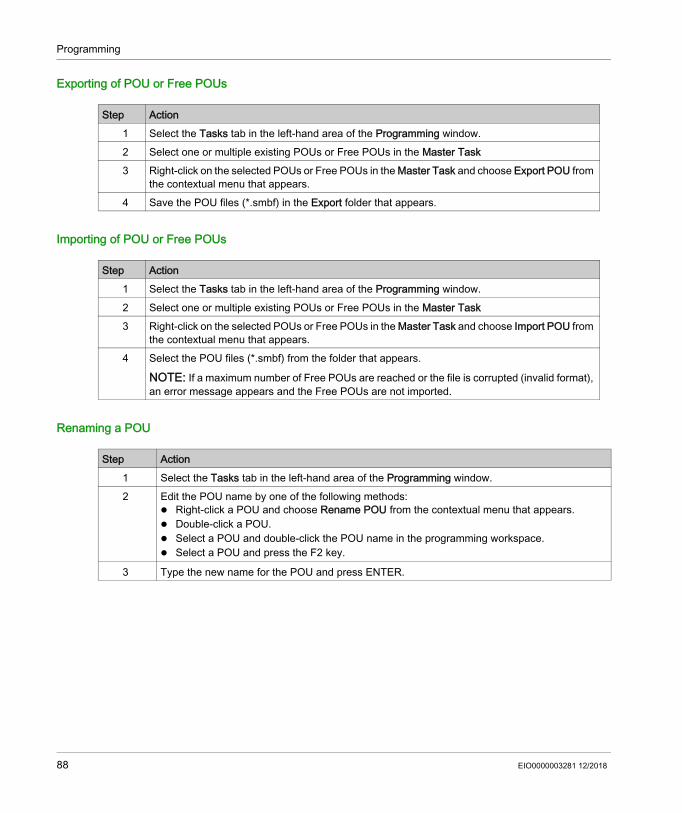
Programming
Exporting of POU or Free POUs
Importing of POU or Free POUs
Renaming a POU
Step Action1 Select the Tasks tab in the left-hand area of the Programming window.2 Select one or multiple existing POUs or Free POUs in the Master Task3 Right-click on the selected POUs or Free POUs in the Master Task and choose Export POU from
the contextual menu that appears.4 Save the POU files (*.smbf) in the Export folder that appears.
Step Action1 Select the Tasks tab in the left-hand area of the Programming window.2 Select one or multiple existing POUs or Free POUs in the Master Task3 Right-click on the selected POUs or Free POUs in the Master Task and choose Import POU from
the contextual menu that appears.4 Select the POU files (*.smbf) from the folder that appears.
NOTE: If a maximum number of Free POUs are reached or the file is corrupted (invalid format), an error message appears and the Free POUs are not imported.
Step Action1 Select the Tasks tab in the left-hand area of the Programming window.2 Edit the POU name by one of the following methods:
Right-click a POU and choose Rename POU from the contextual menu that appears. Double-click a POU. Select a POU and double-click the POU name in the programming workspace. Select a POU and press the F2 key.
3 Type the new name for the POU and press ENTER.
88 EIO0000003281 12/2018
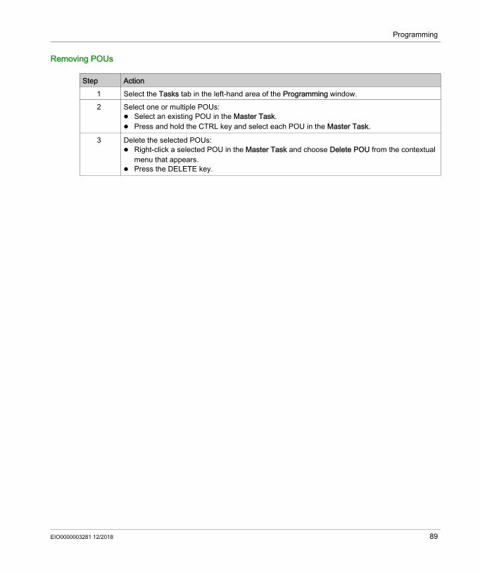
Programming
Removing POUs
Step Action1 Select the Tasks tab in the left-hand area of the Programming window.2 Select one or multiple POUs:
Select an existing POU in the Master Task. Press and hold the CTRL key and select each POU in the Master Task.
3 Delete the selected POUs: Right-click a selected POU in the Master Task and choose Delete POU from the contextual
menu that appears. Press the DELETE key.
EIO0000003281 12/2018 89

Programming
Managing Rungs
Creating a Rung
Inserting a Rung Above an Existing Rung
Step Action1 Select the Tasks tab in the left-hand area of the Programming window.2 Add a rung in a POU by any of the following methods:
Right-click a POU and choose Add Rung from the contextual menu that appears.
Select a POU and click (Add Rung button) on the toolbar at the top of the Tasks tab.
Select a POU and click (Create a new Rung button) on the toolbar at the top of the programming workspace.
Result: A new rung is added to the program structure immediately below the last rung.3 To reposition a rung in a POU, select a rung and click the UP or DOWN button on the toolbar
at the top of the Tasks tab to move the selected rung up or down in the program structure.4 The rung is given sequence identifier, such as Rung0. You may additionally add a rung
comment to identify the rung by clicking the rung header.5 The default programming language is LD (ladder). To select a different programming
language for this rung, click LD and choose a different programming language.6 If this rung is to be called with a JUMP instruction, assign a label to the rung by clicking the
drop-down button below the rung sequence identifier Rungx, where x is the rung number in a POU, and choose %L from the list.Result: The rung is labeled as %Ly, where y is the label number. %L appears on the button and the label number y appears in suffix with the button.
NOTE: The label number is incremented by 1 as you define the next label.
To modify the label number, double-click the label number in a rung and enter the new number and then press ENTER.
Step Action1 Select the Tasks tab in the left-hand area of the Programming window.2 Select an existing rung in the Programming workspace.3
Click (Insert a new Rung button) on the toolbar at the top of the programming workspace.Result: A new rung appears above the selected rung.
90 EIO0000003281 12/2018

Programming
Copying Rungs
NOTE: You can also copy and paste rungs in the Programming window:
4 The rung is given sequence identifier, such as Rung0. You may additionally add a rung comment to identify the rung by clicking the rung header.
5 The default programming language is LD (ladder). To select a different programming language for this rung, click LD and choose a different language.
6 If this rung is to be called with a JUMP instruction, assign a label to the rung by clicking the drop-down button below the rung sequence identifier Rungx, where x is the rung number in a POU, and choose %L from the list.Result: The rung is labeled as %Ly, where y is the label number. %L appears on the button and the label number y appears in suffix with the button.
NOTE: The label number is incremented by 1 as you define the next label.
To modify the label number, double-click the label number in a rung and enter the new number and then press ENTER.
Step Action
Step Action1 Select the Tasks tab in the left-hand area of the Programming window.2 Select one or multiple rungs:
Select an existing rung. Press and hold the CTRL key and select each rung.
3 Right-click one of the selected rungs to copy and do one of the following methods: Choose Copy selected rung from the contextual menu that appears. Press CTRL + C.
4 Right-click a rung and do one the following methods: Choose Paste Rung from the contextual menu that appears. Press CTRL + V.
Result: A copy of the rung is inserted with the same label as the original rung. Edit the label as required.
Step Action1 Right-click the rung to copy and choose Copy selected rung.2 Right-click in the programming workspace and choose Paste Rung.
EIO0000003281 12/2018 91

Programming
Renaming a Rung
Removing Rungs
Step Action1 Select the Tasks tab in the left-hand area of the Programming window.2 Edit the rung name by one of the following methods:
Right-click a rung and choose Rename Rung from the contextual menu that appears. Double-click a rung. Select a rung and double-click the rung name or the text name in the programming
workspace. Select a rung and press the F2 key.
3 Type the new name for the rung and press ENTER.
Step Action1 Select the Tasks tab in the left-hand area of the Programming window.2 Delete a rung by one of the following methods:
Right-click a rung and choose Delete Rung from the contextual menu that appears.
Select a rung and click (Delete Rung button) on the toolbar at the top of the Tasks tab.
Select a rung and click (Delete the Rung button) on the toolbar at the top of the programming workspace.
Right-click a rung in the programming workspace and choose Delete the selected rung from the contextual menu that appears.
Select a rung and press the DELETE key.
3 If the rung is not empty, you are prompted to confirm deleting the rung.
92 EIO0000003281 12/2018
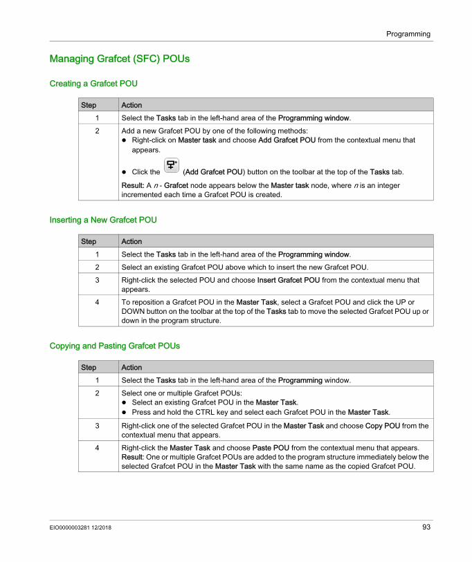
Programming
Managing Grafcet (SFC) POUs
Creating a Grafcet POU
Inserting a New Grafcet POU
Copying and Pasting Grafcet POUs
Step Action1 Select the Tasks tab in the left-hand area of the Programming window.2 Add a new Grafcet POU by one of the following methods:
Right-click on Master task and choose Add Grafcet POU from the contextual menu that appears.
Click the (Add Grafcet POU) button on the toolbar at the top of the Tasks tab.
Result: A n - Grafcet node appears below the Master task node, where n is an integer incremented each time a Grafcet POU is created.
Step Action1 Select the Tasks tab in the left-hand area of the Programming window.2 Select an existing Grafcet POU above which to insert the new Grafcet POU.3 Right-click the selected POU and choose Insert Grafcet POU from the contextual menu that
appears.4 To reposition a Grafcet POU in the Master Task, select a Grafcet POU and click the UP or
DOWN button on the toolbar at the top of the Tasks tab to move the selected Grafcet POU up or down in the program structure.
Step Action1 Select the Tasks tab in the left-hand area of the Programming window.2 Select one or multiple Grafcet POUs:
Select an existing Grafcet POU in the Master Task. Press and hold the CTRL key and select each Grafcet POU in the Master Task.
3 Right-click one of the selected Grafcet POU in the Master Task and choose Copy POU from the contextual menu that appears.
4 Right-click the Master Task and choose Paste POU from the contextual menu that appears.Result: One or multiple Grafcet POUs are added to the program structure immediately below the selected Grafcet POU in the Master Task with the same name as the copied Grafcet POU.
EIO0000003281 12/2018 93

Programming
Renaming a Grafcet POU
Removing Grafcet POUs
Step Action1 Select the Tasks tab in the left-hand area of the Programming window.2 Edit the Grafcet POU name by one of the following methods:
Right-click on a Grafcet POU and choose Rename POU from the contextual menu that appears.
Double-click a Grafcet POU. Select a Grafcet POU and press the F2 key.
3 Type the new name for the Grafcet POU node and press ENTER.
Step Action1 Select the Tasks tab in the left-hand area of the Programming window.2 Select one or multiple Grafcet POUs:
Select an existing Grafcet POU in the Master Task. Press and hold the CTRL key and select each Grafcet POU in the Master Task.
3 Delete the selected Grafcet POUs: Right-click a selected Grafcet POU in the Master Task and choose Delete POU from the
contextual menu that appears. Press the DELETE key.
94 EIO0000003281 12/2018

Programming
Free POUs
IntroductionIn EcoStruxure Machine Expert - Basic, a Free POU is a special type of POU that is not explicitly associated with a task:
Each Free POU is implemented as a subroutine and is made up of 1 or more rungs written in the Ladder or IL programming languages.NOTE: Grafcet POUs cannot be Free POUs.Free POUs are consumed when: Called using a subroutine call (SRi) from within a program rung Configured as the periodic task Configured as an event task, for example, the subroutine for threshold 0 of a High Speed
Counter (HSC) function block (%HSCi.TH0)When consumed as periodic or event tasks, the Free POU subroutine is automatically moved from the Free POUs area of the Tasks window to the Periodic Task or Events area of the window, respectively.When no longer consumed as a periodic task of event task, the subroutine moves back to the Free POUs area and available to be consumed by other tasks or events.
Creating a New Free POUProceed as follows to create a new Free POU:
Step Action1 Select the Tasks tab in the left-hand area of the Programming window.2 Right-click on Free POUs and choose Add Free POU from the contextual menu that appears.
Result: A new POU with the default name “Free POU_0” and default subroutine number “SR0” appears below the Free POUs branch and a new rung appears in the Programming workspace.
3 Optionally, right-click on the new POU and choose Rename POU, then type a new name for the POU and press Enter. The name of the Free POU is also updated in the rung that appears in the Programming workspace.
EIO0000003281 12/2018 95

Programming
Copying and Pasting Existing Free POUsProceed as follows to copy and paste existing POUs associated with a task to create a Free POU:
Copying and Pasting Existing POUs Associated with a Task
4 Optionally, type a comment (see page 186) to associate with the Free POU. 5 Select Subroutine number to the right of the comment box and choose a subroutine number from
the list. Result: The POU description in the Free POUs list is updated with the subroutine number chosen, for example “SR11”.
6 Create the rungs/steps and source code for the Free POU/Free Grafcet POU, in the Ladder or IL programming language.
Step Action
Step Action1 Select the Tasks tab in the left-hand area of the Programming window.2 Select one or multiple Free POUs:
Select an existing Free POU. Press and hold the CTRL key and select each Free POU.
3 Right-click one of the selected Free POU and choose Copy POU from the contextual menu that appears.
4 Right-click and choose Paste POU from the contextual menu that appears.Result: One or multiple new Free POUs with the name Free POU_x, where x is the next available Free POU number, and default subroutine number SRx , where x is the next available subroutine number, appear below Free POUs. All rungs of the POU are automatically associated with the new Free POU subroutine number.
Step Action1 Select the Tasks tab in the left-hand area of the Programming window.2 Select one or multiple POUs:
Select an existing POU in the Master Task. Press and hold the CTRL key and select each POU in the Master Task.
3 Right-click one of the selected POU in the Master Task and choose Copy POU from the contextual menu that appears.
4 Right-click the Master Task and choose Paste POU from the contextual menu that appears.Result: One or multiple POUs are added to the program structure immediately below the selected POU in the Master Task with the same name as the copied POU.
96 EIO0000003281 12/2018

Programming
Exporting of Free POUs
Importing of Free POUs
Removing Free POUsProceed as follows to remove Free POUs:
NOTE: Unassign (see page 127) a Free POU from a task before removing it.
Step Action1 Select the Tasks tab in the upper left-hand area of the Programming window.2 Select one or multiple existing Free POUs in the Master Task.3 Right-click on the selected Free POUs in the Master Task and choose Export POU from the
contextual menu that appears.4 Save the Export Free POU files (*.smbf) in the Export folder that appears.
Step Action1 Select the Tasks tab in the upper left-hand area of the Programming window.2 Select one or multiple existing Free POUs in the Master Task.3 Right-click on the selected Free POUs in the Master Task and choose Import POU from the
contextual menu that appears.4 Select the Free POU files (*.smbf) from the folder that appears, and click Open.
NOTE: If a maximum number of Free POUs is reached or the file is corrupted (invalid format), an error message appears and the Free POUs are not imported.
Step Action1 Select the Tasks tab in the left-hand area of the Programming window.2 Select one or multiple Free POUs:
Select an existing Free POU. Press and hold the CTRL key and select each Free POU.
3 Delete the selected Free POUs: Right-click a selected Free POU and choose Delete POU from the contextual menu that
appears. Press the DELETE key.
EIO0000003281 12/2018 97

Programming
Assigning Free POUs to Events or Periodic TasksBy default, Free POUs and subroutines are not associated with any events or tasks.Refer to Creating Periodic Task (see page 126) for information on how to associate a Free POU with a periodic task.Refer to Creating Event Task (see page 133) for information on how to associate a Free POU with an event.
98 EIO0000003281 12/2018

Programming
User-Defined Functions
Section 5.5User-Defined Functions
OverviewA user-defined function allows you to create new functions with input parameters, local variables and a return value. User-defined functions are stored as part of the EcoStruxure Machine Expert - Basic project.You can call user-defined functions in: The Master task Periodic tasks Events Free POUsNOTE: The application must be configured with a functional level (see page 80) of at least Level 6.0 to support user-defined functions.
What Is in This Section?This section contains the following topics:
Topic PageCreating a User-Defined Function 100Defining a User-Defined Function 101Managing User-Defined Functions 105
EIO0000003281 12/2018 99

Programming
Creating a User-Defined Function
Adding a New User-Defined FunctionYou can have up to 64 user-defined functions in a project.
You create and manage rungs in a user-defined function in the same way as rungs in a POU. Refer to Managing Rungs (see page 90).
Step Action1 Select the Tasks tab in the left-hand area of the Programming window.2 Create a user-defined function using one of the following methods:
Right-click User-defined functions and choose Add user-defined function from the contextual menu that appears.
Select User-defined functions and click (Add user-defined-function) on the toolbar at the top of the Tasks tab.
Select an existing user-defined function, right click and choose Insert user-defined function.
Result: A new user-defined function is added to the program structure at the bottom of the list. If you inserted a user-defined function, the new user-defined function is above the selected one. The default name is FUNCTIONn, where n is an integer incremented each time a user-defined function is created.
3 Optionally, rename the user-defined function. Refer to Renaming a User-Defined Function (see page 106).
4 Define the user-defined function. Refer to Defining a User-Defined Function (see page 101).
100 EIO0000003281 12/2018

Programming
Defining a User-Defined Function
PresentationThe following illustration shows the actions that are available in the Properties view of the user-defined function:
1 Delete the Return value, an input Parameter, or a Local variable2 Add a Return value, an input Parameter, or a Local variable3 Optionally, write a description of the purpose of the user-defined function. This description appears in a
tooltip when you use the user-defined function in an Operation Block or Comparison Block.4 Detach the properties view
EIO0000003281 12/2018 101

Programming
Programming a User-Defined FunctionTo program a user-defined function:
You can also directly program the user-defined function in the IL editor:
You can call other user-defined functions in the rungs that implement a user-defined function.NOTE: User-defined functions cannot be recursive: a user-defined function cannot call itself directly or indirectly.Example:
- - - Not allowed
A user-defined function cannot call a subroutine, but a subroutine can call a user-defined function.
Step Action1 Add a new user-defined function. Refer to Adding a User-Defined Function (see page 100).2 Define the interface of the user-defined function by defining the Return value, the input
Parameters and the Local variables. Refer to Defining the Interface of a User-Defined Function (see page 103).
3 Click Apply.4 Define the functionality of the user-defined function in one or more Ladder/IL rungs
(see page 90):1. Insert a Ladder structure element.2. Program the user-defined function.For example:
102 EIO0000003281 12/2018
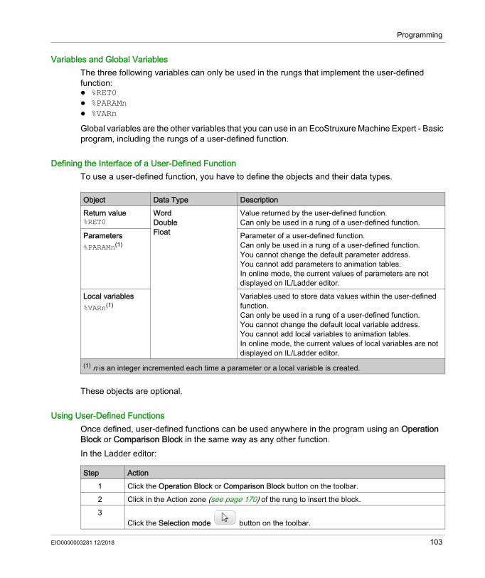
Programming
Variables and Global VariablesThe three following variables can only be used in the rungs that implement the user-defined function: %RET0 %PARAMn %VARn
Global variables are the other variables that you can use in an EcoStruxure Machine Expert - Basic program, including the rungs of a user-defined function.
Defining the Interface of a User-Defined FunctionTo use a user-defined function, you have to define the objects and their data types.
These objects are optional.
Using User-Defined FunctionsOnce defined, user-defined functions can be used anywhere in the program using an Operation Block or Comparison Block in the same way as any other function.In the Ladder editor:
Object Data Type DescriptionReturn value%RET0
WordDoubleFloat
Value returned by the user-defined function.Can only be used in a rung of a user-defined function.
Parameters%PARAMn(1)
Parameter of a user-defined function.Can only be used in a rung of a user-defined function.You cannot change the default parameter address.You cannot add parameters to animation tables.In online mode, the current values of parameters are not displayed on IL/Ladder editor.
Local variables%VARn(1)
Variables used to store data values within the user-defined function.Can only be used in a rung of a user-defined function.You cannot change the default local variable address.You cannot add local variables to animation tables.In online mode, the current values of local variables are not displayed on IL/Ladder editor.
(1) n is an integer incremented each time a parameter or a local variable is created.
Step Action1 Click the Operation Block or Comparison Block button on the toolbar.2 Click in the Action zone (see page 170) of the rung to insert the block.3
Click the Selection mode button on the toolbar.
EIO0000003281 12/2018 103

Programming
4 Double-click the operation expression line.You can either: Type the name of the user-defined function. For example, for the name “FUNCTION1”, type
“FU” and the names of all user-defined functions that begin with “FU” appear:
Use Smart Coding (see page 183):
a. Click the Smart Coding button.b. Select Filter by category then User-defined function.c. Select the user-defined function.
5 Click Insert Function.6 Complete the definition of the user-defined function by typing the return value and the
parameters as defined in Defining the Interface of a User-Defined Function (see page 103).
Step Action
104 EIO0000003281 12/2018

Programming
Managing User-Defined Functions
User-Defined Functions in Offline and Online ModesYou can manage user-defined functions in offline mode.In online mode, you can: add a rung to an existing user-defined function modify a rung calling a user-defined function
Copying/Cutting and Pasting Existing User-Defined Functions
Exporting User-Defined FunctionsUser-defined functions are stored as part of the project. If you want to use a user-defined function in another project, you have to export it, then import it to the other project.You can copy/paste between EcoStruxure Machine Expert - Basic instances.
Step Action1 Select the Tasks tab in the left-hand area of the Programming window.2 Select one or more user-defined functions:
Click to select a user-defined function. Select multiple user-defined functions by pressing and holding the CTRL key.
3 Right-click and choose Copy user-defined functions or Cut user-defined functions from the contextual menu that appears.
4 Right-click User-defined functions and choose Paste user-defined function from the contextual menu that appears.Result: One or more user-defined functions are added at the end of the program structure in User-defined functions. EcoStruxure Machine Expert - Basic automatically assigns new name to the copied user-defined function.
Step Action1 Select the Tasks tab in the left-hand area of the Programming window.2 Select one or more user-defined functions:
Click to select a user-defined function. Select multiple user-defined functions by pressing and holding the CTRL key.
3 Right-click the selected user-defined functions in User-defined functions and choose Export user-defined function from the contextual menu that appears.
4 Save the user-defined function file (*.smbf) in the Export folder that appears.
EIO0000003281 12/2018 105
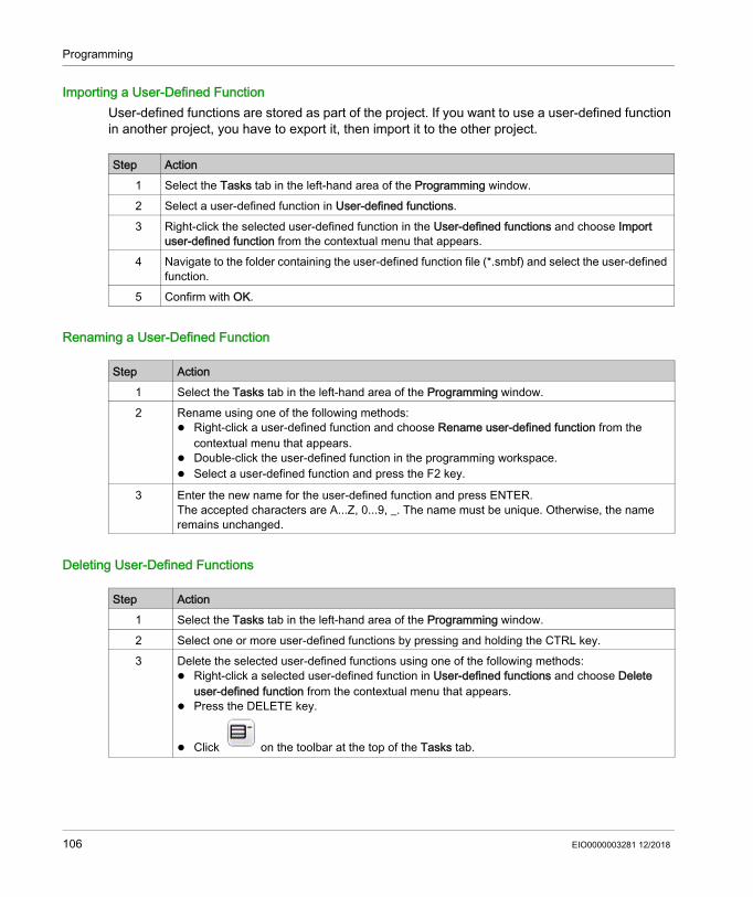
Programming
Importing a User-Defined FunctionUser-defined functions are stored as part of the project. If you want to use a user-defined function in another project, you have to export it, then import it to the other project.
Renaming a User-Defined Function
Deleting User-Defined Functions
Step Action1 Select the Tasks tab in the left-hand area of the Programming window.2 Select a user-defined function in User-defined functions.3 Right-click the selected user-defined function in the User-defined functions and choose Import
user-defined function from the contextual menu that appears.4 Navigate to the folder containing the user-defined function file (*.smbf) and select the user-defined
function.5 Confirm with OK.
Step Action1 Select the Tasks tab in the left-hand area of the Programming window.2 Rename using one of the following methods:
Right-click a user-defined function and choose Rename user-defined function from the contextual menu that appears.
Double-click the user-defined function in the programming workspace. Select a user-defined function and press the F2 key.
3 Enter the new name for the user-defined function and press ENTER.The accepted characters are A...Z, 0...9, _. The name must be unique. Otherwise, the name remains unchanged.
Step Action1 Select the Tasks tab in the left-hand area of the Programming window.2 Select one or more user-defined functions by pressing and holding the CTRL key.3 Delete the selected user-defined functions using one of the following methods:
Right-click a selected user-defined function in User-defined functions and choose Delete user-defined function from the contextual menu that appears.
Press the DELETE key.
Click on the toolbar at the top of the Tasks tab.
106 EIO0000003281 12/2018

Programming
User-Defined Function Blocks
Section 5.6User-Defined Function Blocks
OverviewA user-defined function block allows you to create new function blocks with one or more input and output parameters, and local variables. User-defined function blocks are stored as part of the EcoStruxure Machine Expert - Basic project.You can call user-defined function blocks in: The Master task Periodic tasks Events Free POUsNOTE: The application must be configured with a functional level (see page 80) of at least Level 6.0 to support user-defined function blocks.
What Is in This Section?This section contains the following topics:
Topic PageCreating a User-Defined Function Block 108Defining a User-Defined Function Block 109Managing User-Defined Function Blocks 113
EIO0000003281 12/2018 107
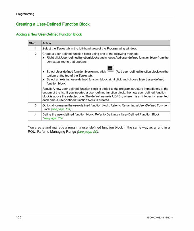
Programming
Creating a User-Defined Function Block
Adding a New User-Defined Function Block
You create and manage a rung in a user-defined function block in the same way as a rung in a POU. Refer to Managing Rungs (see page 90).
Step Action1 Select the Tasks tab in the left-hand area of the Programming window.2 Create a user-defined function block using one of the following methods:
Right-click User-defined function blocks and choose Add user-defined function block from the contextual menu that appears.
Select User-defined function blocks and click (Add user-defined function block) on the toolbar at the top of the Tasks tab.
Select an existing user-defined function block, right click and choose Insert user-defined function block.
Result: A new user-defined function block is added to the program structure immediately at the bottom of the list. If you inserted a user-defined function block, the new user-defined function block is above the selected one. The default name is UDFBn, where n is an integer incremented each time a user-defined function block is created.
3 Optionally, rename the user-defined function block. Refer to Renaming a User-Defined Function Block (see page 114).
4 Define the user-defined function block. Refer to Defining a User-Defined Function Block (see page 109).
108 EIO0000003281 12/2018

Programming
Defining a User-Defined Function Block
PresentationThe following illustration shows the actions that are available in the Properties view of the user-defined function:
1 Add an input or output2 Delete an input or output3 Delete the Parameter or the Local variable4 Add a Parameter or a Local variable5 Optionally, write a description of the purpose of the user-defined function block. This description appears
in a tooltip when you use the user-defined function block in an Operation block.6 Detach the properties view7 Number of instances in the user logic for this function block definition
EIO0000003281 12/2018 109

Programming
Programming a User-Defined Function BlockTo program a user-defined function block:
You cannot program a user-defined function block in the IL editor.
Local and Global VariablesThe local variables are variables that can only be used in the rungs that implement the user-defined function block: %PARAMn %VARn
Global variables are all other variables you can use in an EcoStruxure Machine Expert - Basic program, including the rungs of a user-defined function block.
Step Action1 Add a new user-defined function block. Refer to Adding a User-Defined Function Block
(see page 108).2 Define the interface of the user-defined function block by defining the input Parameters and the
Local variables. Refer to Defining the Interface of a User-Defined Function Block (see page 111).
3 Click Apply.4 Specify the functionality of the user-defined function block in one or more Ladder/IL rungs
(see page 90):
1. Click the Function blocks button on the toolbar.
2. Select → the user-defined function block you want to insert.3. Click in the Action zone (see page 170) of the rung.4. Program the user-defined function block.
110 EIO0000003281 12/2018

Programming
Defining the Interface of a User-Defined Function BlockTo use a user-defined function block you have to define the inputs, outputs, object types and their data types.
Using a User-Defined Function BlockTo insert a user-defined function block into a rung:
Object type Data Type DescriptionInputs/outputs Boolean Input and output pins for the function block.Parameters%PARAMn(1)
WordDoubleFloat
Can only be used in a rung of a user-defined function and user-defined function block.You cannot change the default parameter address.You can add parameters to animation tables.
Local variables%VARn(1)
Can only be used in a rung of a user-defined function and user-defined function block.You cannot change the default local variable address.You can add local variables to animation tables.
(1) n is an integer incremented each time a parameter or a local variable is created.
Step Action1
Click the Function blocks button on the toolbar.2
Select → the user-defined function block you want to insert.3 Click in the Action zone (see page 170) of the rung.4 Optionally use operation blocks to read or write function block parameters.
The syntax is %<UDFB name><instance number>.PARAMn, where n is an integer corresponding to the parameter number.Example: You defined a user-defined function block named MY_FB with a parameter %PARAM0. An instance of this user-defined function block is placed in the Master task and the instance
number 0 is assigned to it.Result: The object %MY_FB0.PARAM0 is available in any tasks.
EIO0000003281 12/2018 111
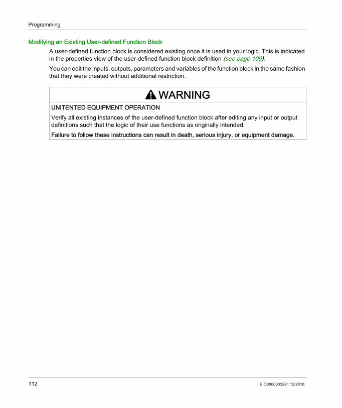
Programming
Modifying an Existing User-defined Function BlockA user-defined function block is considered existing once it is used in your logic. This is indicated in the properties view of the user-defined function block definition (see page 109).You can edit the inputs, outputs, parameters and variables of the function block in the same fashion that they were created without additional restriction.
WARNINGUNITENTED EQUIPMENT OPERATIONVerify all existing instances of the user-defined function block after editing any input or output definitions such that the logic of their use functions as originally intended.Failure to follow these instructions can result in death, serious injury, or equipment damage.
112 EIO0000003281 12/2018

Programming
Managing User-Defined Function Blocks
User-Defined Function Blocks in Offline and Online ModesYou can manage the user-defined function blocks in offline mode.In online mode, you can: add a rung to an existing user-defined function block copy/paste a user-defined function block import/export a user-defined function block modify a rung calling a user-defined function block
Copying/Cutting and Pasting Existing User-Defined Function Blocks
Exporting User-Defined Function BlocksUser-defined function blocks are stored as part of the project. If you want to use a user-defined function block in another project, you have to export it, then import it to the other project.
Step Action1 Select the Tasks tab in the left-hand area of the Programming window.2 Select one or more user-defined function blocks:
Click to select a user-defined function block. Select multiple user-defined function blocks by pressing and holding the CTRL key.
3 Right-click and choose Copy user-defined function blocks or Cut user-defined function blocks from the contextual menu that appears.
4 Right-click User-defined function blocks and choose Paste user-defined function block from the contextual menu that appears.Result: One or more user-defined function blocks are added at the end of the program structure in User-defined function blocks. EcoStruxure Machine Expert - Basic automatically assigns new name to the copied user-defined function block.
Step Action1 Select the Tasks tab in the left-hand area of the Programming window.2 Select one or more user-defined function blocks:
Click to select a user-defined function block. Select multiple user-defined function blocks by pressing and holding the CTRL key.
3 Right-click the selected user-defined function blocks in User-defined function blocks and choose Export user-defined function block from the contextual menu that appears.
4 Save the user-defined function block file (*.smbf) in the Export folder that appears.
EIO0000003281 12/2018 113
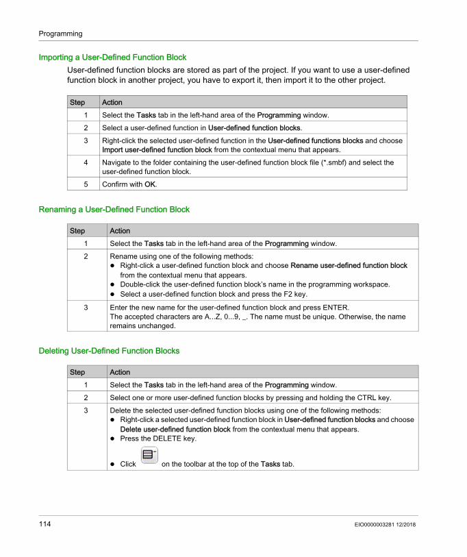
Programming
Importing a User-Defined Function BlockUser-defined function blocks are stored as part of the project. If you want to use a user-defined function block in another project, you have to export it, then import it to the other project.
Renaming a User-Defined Function Block
Deleting User-Defined Function Blocks
Step Action1 Select the Tasks tab in the left-hand area of the Programming window.2 Select a user-defined function in User-defined function blocks.3 Right-click the selected user-defined function in the User-defined functions blocks and choose
Import user-defined function block from the contextual menu that appears.4 Navigate to the folder containing the user-defined function block file (*.smbf) and select the
user-defined function block.5 Confirm with OK.
Step Action1 Select the Tasks tab in the left-hand area of the Programming window.2 Rename using one of the following methods:
Right-click a user-defined function block and choose Rename user-defined function block from the contextual menu that appears.
Double-click the user-defined function block’s name in the programming workspace. Select a user-defined function block and press the F2 key.
3 Enter the new name for the user-defined function block and press ENTER.The accepted characters are A...Z, 0...9, _. The name must be unique. Otherwise, the name remains unchanged.
Step Action1 Select the Tasks tab in the left-hand area of the Programming window.2 Select one or more user-defined function blocks by pressing and holding the CTRL key.3 Delete the selected user-defined function blocks using one of the following methods:
Right-click a selected user-defined function block in User-defined function blocks and choose Delete user-defined function block from the contextual menu that appears.
Press the DELETE key.
Click on the toolbar at the top of the Tasks tab.
114 EIO0000003281 12/2018
Programming
Master Task
Section 5.7Master Task
What Is in This Section?This section contains the following topics:
Topic PageMaster Task Description 116Configuring Master Task 117
EIO0000003281 12/2018 115

Programming
Master Task Description
OverviewThe master task represents the main task of the application program. It is obligatory and is created by default. The master task is made up of sections and subroutines represented within Program Organizational Units (POUs). Each POU of the master task can be programmed in any of the supported programming languages.
Procedure
For Refer ToCreating a new POU in the master task Creating a New POU Associated with a Task (see page 87)Renaming a POU in the master task Renaming a POU (see page 88)Removing a POU from the master task Removing a POU (see page 89)
116 EIO0000003281 12/2018

Programming
Configuring Master Task
ProcedureFollow these steps to configure the master task:
Master Task PropertiesScan ModeChoose the scan mode to use for the program: Normal: When a logic controller is in normal (freewheeling) scan mode, a new scan starts
immediately after the previous scan has completed. Periodic: In periodic scan mode, the logic controller waits until the configured scan time has
elapsed before starting a new scan. Every scan is therefore the same duration.Specify the scan Period for the periodic scan mode of 1...150 ms.
System Bits and Words Controlling the Master TaskThe master task can be controlled by system bits (%S) and system words (%SW):This table lists the system bits:
Step Action1 Select the Tasks tab in the left-hand area of the Programming window.2 Select the Master Task item.
Result: The Master Task properties appear in the lower central area of the EcoStruxure Machine Expert - Basic window.
3 Modify the properties as required.4 Click Apply to save the changes.
System BIts Description%S11 Watchdog overflow%S19 Scan period overrun (periodic scan mode)
EIO0000003281 12/2018 117
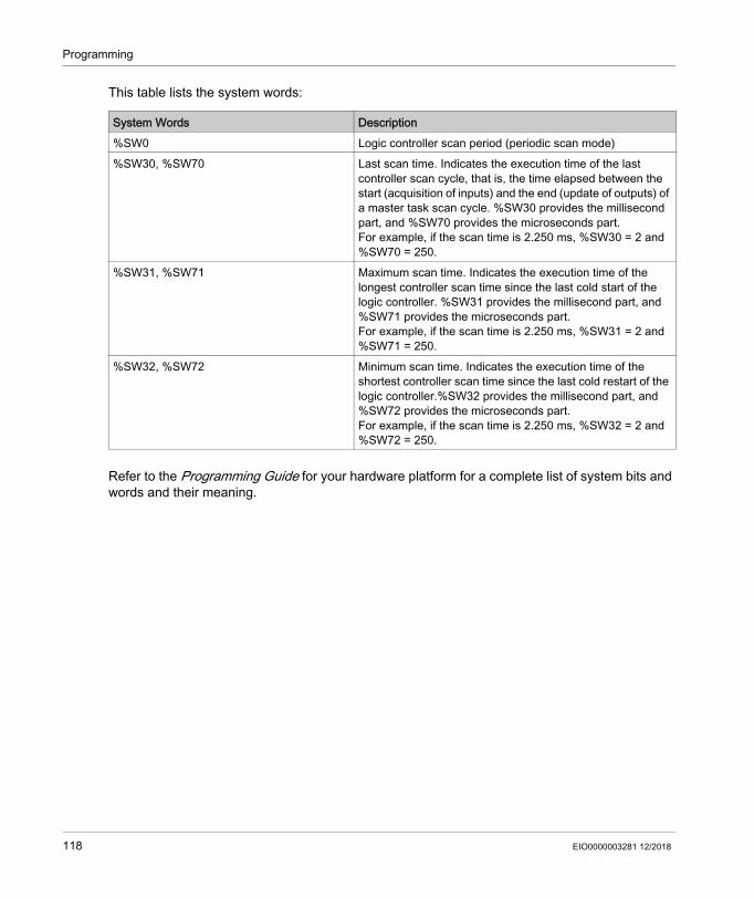
Programming
This table lists the system words:
Refer to the Programming Guide for your hardware platform for a complete list of system bits and words and their meaning.
System Words Description%SW0 Logic controller scan period (periodic scan mode)%SW30, %SW70 Last scan time. Indicates the execution time of the last
controller scan cycle, that is, the time elapsed between the start (acquisition of inputs) and the end (update of outputs) of a master task scan cycle. %SW30 provides the millisecond part, and %SW70 provides the microseconds part.For example, if the scan time is 2.250 ms, %SW30 = 2 and %SW70 = 250.
%SW31, %SW71 Maximum scan time. Indicates the execution time of the longest controller scan time since the last cold start of the logic controller. %SW31 provides the millisecond part, and %SW71 provides the microseconds part.For example, if the scan time is 2.250 ms, %SW31 = 2 and %SW71 = 250.
%SW32, %SW72 Minimum scan time. Indicates the execution time of the shortest controller scan time since the last cold restart of the logic controller.%SW32 provides the millisecond part, and %SW72 provides the microseconds part.For example, if the scan time is 2.250 ms, %SW32 = 2 and %SW72 = 250.
118 EIO0000003281 12/2018

Programming
Strings
Section 5.8Strings
OverviewStrings are a sequence of bytes containing ASCII characters that you can store in the following memory objects: Memory words %MW Constant words %KW
There are two bytes in one word.Syntax to program a string:
The supported controllers have a little-endian architecture; the bytes are stored from the lowest order byte to the highest.The following table shows you an example of the storage of the bytes for the string Basic:
You can write up to 509 characters.NOTE: The memory objects are used as a variable or for a string. If you have configured a memory object for a string, do not configure any of the memory words it contains as a variable.
What Is in This Section?This section contains the following topics:
%MWx:L
x Index of the memory objectL Number of words used by the string and must be between 1...255.
Memory objects Hexadecimal ASCII%MW0 or %KW0 6142 aB
%MW1 or %KW1 6973 is
%MW2 or %KW2 0D63 \rc (1)
(1) \r is the marker representing the end character of the string. This marker is mandatory and taken into account when processing the strings.
Topic PageConfiguring Strings in Constant words 120Assigning Strings in Memory Words 121Managing Strings 122
EIO0000003281 12/2018 119

Programming
Configuring Strings in Constant words
Entering a String
Result: The entered characters are applied to the corresponding and required constant variables. The characters are inverted. Refer to the overview of this section (see page 119).
Step Action1 In the Programming window, click Tools → Memory objects → Constant words.2 In Constant word properties, click %KW.3
Click the button in the Configuration column for the constant word that you want to configure.If the constant word is already configured the Confirmation window appears. Click Ok to overwrite the value. Otherwise, click Cancel.Result: The Constant string Assistant window appears.
4 Enter the string.Result: Range of constants required, including the termination marker, is displayed below the input text box for the string.
5 Click Apply.
120 EIO0000003281 12/2018

Programming
Assigning Strings in Memory Words
SyntaxThe following describes Instruction List syntax. You can insert Instruction List operations and assignment instructions (see page 182) in Ladder Diagram rungs using an Operation Block graphical element.For assigning a string in a memory word, use this syntax: Op1 := "Your string".
For example:%MW10:20 := "This is a Basic string."
If you want the software to calculate the memory space needed, type %MWx:? := "Your string".
Rules of UseWhen you assign a string: Make sure there is no overlapping. You can overwrite a string by another string. The use of the quotation character is not supported for immediate string assignments.
EIO0000003281 12/2018 121

Programming
Managing Strings
IntroductionThe following functions allow you to: Copy a string. Get the length of a string. Concatenate two strings. Compare two strings.
SyntaxThe following describes Instruction List syntax. You can insert Instruction List operations and assignment instructions (see page 182) in Ladder Diagram rungs using an Operation Block graphical element.
Copying a StringFor copying a string, use this syntax: Op1 := Op2.
The following table presents the authorized memory objects for Op1 and Op2:
Getting the Length of a StringFor getting the length of a string, use this syntax: Op1 := LENGTH(Op2).
The following table presents the authorized memory objects for Op1 and Op2:
Immediate strings are not accepted.
Parameters DescriptionOp1 %MWx:L
Op2 %MWy:L or %KWy:L
x, y Indexes of the memory objectL must be the same for both Op1 and Op2
Parameters DescriptionOp1 %MWx
Op2 %MWy:L or %KWy:L
x, y Indexes of the memory object
122 EIO0000003281 12/2018

Programming
Concatenating Two StringsFor concatenating two strings, use this syntax: Op1 := CONCAT(Op2, Op3).
The following table presents the authorized memory objects for Op1, Op2 and Op3:
Immediate strings are not accepted.The following table presents the process of concatenation:
Comparing Two StringsFor comparing two strings, use this syntax: Op1 := EQUAL_STR(Op2, Op3).
The following table presents the authorized memory objects for Op1, Op2 and Op3:
Parameters DescriptionOp1 %MWx:L
Op2 %MWy:A or %KWy:A
Op3 %MWz:B or %KWz:B
x, y, z Indexes of the memory object
EcoStruxure Machine Expert - Basic does not validate that L is sufficiently sized for the concatenation. Be sure that Op1 is of an adequate, minimum length for the operation.
Stage Description1 The application copies Op2 into Op1.2 The copy stops if:
The end character of Op2 is reached. The memory space assigned to Op2 is copied. %S28 is set to TRUE. Refer to System Bits
Description. The entire memory space of Op1 is filled. %S28 is set to TRUE.
3 If the memory space of Op1 is not filled, the application continues by copying Op3 into Op1.4 The copy stops if:
The end character of Op3 is reached. The memory space assigned to Op3 is copied. %S28 is set to TRUE. The entire memory space of Op1 is filled. %S28 is set to TRUE.
5 The application ensures that Op1 ends with the end character. The last character of Op1 may be replaced by the end character if the memory space is filled.
Parameters DescriptionOp1 %MWx
Op2 %MWy:A or %KWy:A
Op3 %MWz:B or %KWz:B
x, y, z Indexes of the memory object
EIO0000003281 12/2018 123

Programming
When the application detects a different character, Op1 equals the index position of the first different character encountered left to right.The following table presents examples of the result of string comparison:
The following table presents the process of a string comparison:
Op2 Op3 Different character Op1azerty qwerty First one 0123456 124356 Third one 2EcoStruxure Machine Expert - Basic
EcoStruxure Machine Expert - Basic
– -1
If And if ThenThe application reaches the end character of Op2
Op2 = Op3 Op1 := -1
Op2 ≠Op3 Op1 equals the different character position.
The application finds a different character before reaching the end of Op2 or Op3.
– Op1 equals the different character position.
The end of the memory space assigned to Op2 or Op3 is reached
A ≠ B Op1 equals the different character position and %S28 is set to TRUE. Refer to System Bits Description.
A = B Op1 := -1 and %S28 is raised.
124 EIO0000003281 12/2018

Programming
Periodic Task
Section 5.9Periodic Task
What Is in This Section?This section contains the following topics:
Topic PageCreating Periodic Task 126Configuring Periodic Task Scan Duration 128
EIO0000003281 12/2018 125

Programming
Creating Periodic Task
OverviewA periodic task is a subroutine, usually of short duration, that is processed periodically. In EcoStruxure Machine Expert - Basic, this subroutine is implemented as a Free POU (see page 95). The subroutine can be written in any of the programming languages supported by EcoStruxure Machine Expert - Basic.
Assigning a Subroutine to a Periodic Task
Step Action1 Create a new Free POU (see page 95) containing the periodic task subroutine.2 Select the Tasks tab in the left-hand area of the Programming window.3 Assign a subroutine to the periodic task by one of the following methods:
Select the Periodic Task and click (Assign Free POU button) on the toolbar at the top of the Tasks tab.
Right-click the Periodic Task and choose Assign Free POU from the contextual menu that appears.
Result: The Select a Free POU window is displayed:
NOTE: You can directly add a Free POU to the periodic task. Right-click the Periodic Task and choose Add Free POU from the contextual menu that appears. In this case, a Free POU is created and assigned to the periodic task.
126 EIO0000003281 12/2018

Programming
Removing a Subroutine from a Periodic Task
4 Select a Free POU to assign to the periodic task and click OK.Result: The selected subroutine is assigned to the Periodic Task and no longer avaialble in the Free POU branch of the Tasks tab.For example, if the Free POU “Free POU_0” containing the subroutine SR4 is assigned to the periodic task, the Free POU_0 (%SR4) subroutine moves from the Free POU branch to the Periodic Task branch of the Tasks tab.
Step Action
Step Action1 Click the Tasks tab in the left-hand area of the Programming window.2 Remove the subroutine from the Periodic Task by one of the following methods:
Select the Periodic Task and click (Unassign Free POU button) on the toolbar at the top of the Tasks tab.
Right-click the Periodic Task and choose Unassign Free POU from the contextual menu that appears.
Result: The selected subroutine is removed from the Periodic Task and available as a Free POU in the Free POUs branch of the Tasks tab.
EIO0000003281 12/2018 127

Programming
Configuring Periodic Task Scan Duration
ProcedureFollow these steps to configure scan duration for periodic task:
Periodic Task PropertiesSpecify the scan Period for the periodic task from 1...255 ms. The default value is 255 ms.
Step Action1 Select the Tasks tab in the left-hand area of the Programming window.2 Select the Periodic Task item.
Result: The Periodic Task properties appear in the lower central area of the EcoStruxure Machine Expert - Basic window.
3 Modify the properties as required.4 Click Apply to save the changes.
128 EIO0000003281 12/2018

Programming
Event Task
Section 5.10Event Task
What Is in This Section?This section contains the following topics:
Topic PageOverview of Event Tasks 130Event Sources 131Event Priorities 132Viewing Event Tasks 133
EIO0000003281 12/2018 129

Programming
Overview of Event Tasks
IntroductionAn event task: Is a part of a program executed when a given condition is met (event source) Has a higher priority than the main program Produces a rapid response time, enabling the overall response time of the system to be
reduced.
Description of an EventAn event is composed of: An event source: a software or hardware condition that interrupts the program when the event
is triggered. A POU: an independent program entity (subroutine) associated with an event. A priority level: a priority assigned to events to determine the order in which they are executed.
130 EIO0000003281 12/2018
Programming
Event Sources
Overview8 event sources are available: 4 linked to selected physical inputs of the logic controller 4 linked to the HSC function block thresholds
An event source is always attached to a single event. When an event is triggered, it interrupts the controller, which then executes the subroutine associated with the event.
Physical Input Events of a Logic ControllerThe embedded digital inputs %I0.2, %I0.3, %I0.4 and %I0.5 of a logic controller can be configured as event sources (filtering must be disabled).For each of these event sources, you can choose to: Trigger events on detection of a rising edge, falling edge, or both rising and falling edges Assign a priority to the event Identify the subroutine associated with the event.For further details on configuring input events, refer to the Programming Guide of the logic controller.
Threshold Output Event of an %HSC Function BlockThe threshold outputs TH0 and TH1 of the %HSC function block can be used as event sources. Outputs TH0 and TH1 are set as follows: TH0 = 0 and TH1 = 0 when the value is less than threshold S0 and threshold S1 TH0 = 1 and TH1 = 0 when the value is greater than threshold S0 and less than threshold S1 TH0 = 1 and TH1 = 1 when the value is greater than threshold S0 and threshold S1For each of these event sources, you can choose to: Trigger events on detection of a rising edge, falling edge, or both rising and falling edges. Assign a priority to the event. Identify the subroutine associated with the event.A rising or falling edge of these outputs can activate an event process.For further details on configuring output event, refer to the Programming Guide of the logic controller.
EIO0000003281 12/2018 131

Programming
Event Priorities
Event PrioritiesEvents have one of 8 possible priorities, from 7 (the lowest) to 0 (the highest). Assign a priority to each event source. Two events cannot have the same priority. Thus, the order of execution depends on their relative priorities and the order in which they are detected.Event tasks interrupt both master and periodic task execution. For more information, refer to Event Priority Over Master and Periodic Tasks (see page 84).NOTE: Care must be exercised when writing to global areas of memory or affecting I/O values when event tasks are called during the execution of other tasks. Modifying values that are otherwise used in the other tasks could affect logical outcomes of those tasks adversely.
For configuring the event task priorities, refer to Programming Guide of your controller.
Event ManagementEach time an interrupt linked to an event source appears, the following sequence is launched:
WARNINGUNINTENDED EQUIPMENT OPERATIONThoroughly test and validate all tasks (Master, Periodic and any Event tasks) and the interactive affect they have on one another before putting your application into service.Failure to follow these instructions can result in death, serious injury, or equipment damage.
Step Description1 Interrupt event occurs.2 Save the context.3 Execution of the programming section (subroutine labeled SRi:) linked to the event.4 Update the embedded outputs.5 Restore the context.
132 EIO0000003281 12/2018

Programming
Viewing Event Tasks
OverviewEvent tasks are displayed in the Configuration tab. Refer to Configuring Digital Inputs.You can display configured event sources, subroutines attached to events, and verify the status of events using system bits and words.To display the event sources and subroutines (Free POUs) assigned to events:
NOTE: Only embedded controller inputs/outputs can be used in an event subroutine.
Step Action1 Select the Tasks tab in the left-hand area of the Programming window.2 Select Events:
NOTE: Configured event sources that have not yet been assigned a subroutine appear in red.
EIO0000003281 12/2018 133
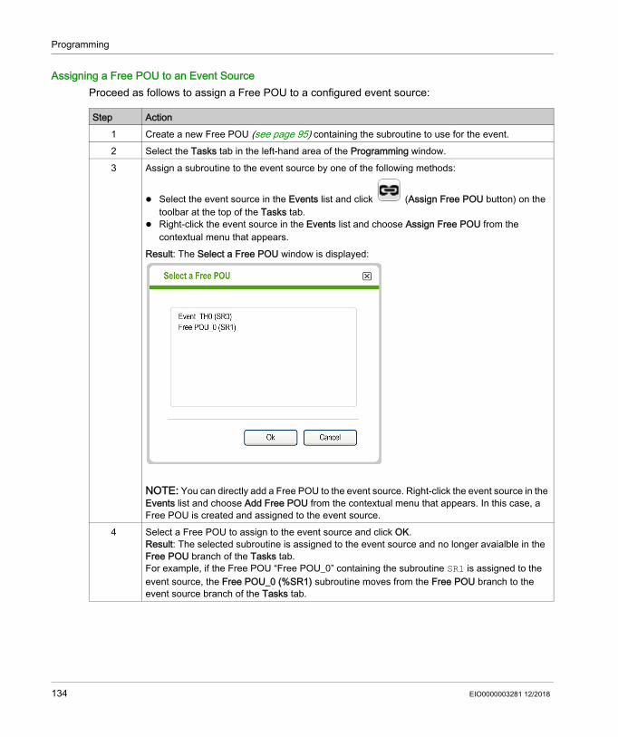
Programming
Assigning a Free POU to an Event SourceProceed as follows to assign a Free POU to a configured event source:
Step Action1 Create a new Free POU (see page 95) containing the subroutine to use for the event.2 Select the Tasks tab in the left-hand area of the Programming window.3 Assign a subroutine to the event source by one of the following methods:
Select the event source in the Events list and click (Assign Free POU button) on the toolbar at the top of the Tasks tab.
Right-click the event source in the Events list and choose Assign Free POU from the contextual menu that appears.
Result: The Select a Free POU window is displayed:
NOTE: You can directly add a Free POU to the event source. Right-click the event source in the Events list and choose Add Free POU from the contextual menu that appears. In this case, a Free POU is created and assigned to the event source.
4 Select a Free POU to assign to the event source and click OK.Result: The selected subroutine is assigned to the event source and no longer avaialble in the Free POU branch of the Tasks tab.For example, if the Free POU “Free POU_0” containing the subroutine SR1 is assigned to the event source, the Free POU_0 (%SR1) subroutine moves from the Free POU branch to the event source branch of the Tasks tab.
134 EIO0000003281 12/2018
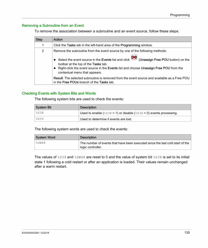
Programming
Removing a Subroutine from an EventTo remove the association between a subroutine and an event source, follow these steps:
Checking Events with System Bits and WordsThe following system bits are used to check the events:
The following system words are used to check the events:
The values of %S39 and %SW48 are reset to 0 and the value of system bit %S38 is set to its initial state 1 following a cold restart or after an application is loaded. Their values remain unchanged after a warm restart.
Step Action1 Click the Tasks tab in the left-hand area of the Programming window.2 Remove the subroutine from the event source by one of the following methods:
Select the event source in the Events list and click (Unassign Free POU button) on the toolbar at the top of the Tasks tab.
Right-click the event source in the Events list and choose Unassign Free POU from the contextual menu that appears.
Result: The selected subroutine is removed from the event source and available as a Free POU in the Free POUs branch of the Tasks tab.
System Bit Description%S38 Used to enable (%S38 = 1) or disable (%S38 = 0) events processing.%S39 Used to determine if events are lost.
System Word Description%SW48 The number of events that have been executed since the last cold start of the
logic controller.
EIO0000003281 12/2018 135

Programming
Using Tools
Section 5.11Using Tools
What Is in This Section?This section contains the following topics:
Topic PageMessages 137Animation Tables 139Memory Objects 145System Objects 150I/O Objects 151Network Objects 152Software Objects 153PTO Objects 154Drive Objects 155Communication Objects 156Search and Replace 157Cross Reference 159Symbol List 160Memory Consumption View 165
136 EIO0000003281 12/2018
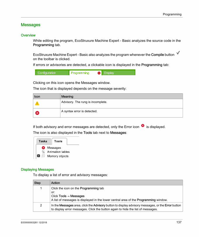
Programming
Messages
OverviewWhile editing the program, EcoStruxure Machine Expert - Basic analyzes the source code in the Programming tab.
EcoStruxure Machine Expert - Basic also analyzes the program whenever the Compile button on the toolbar is clicked.If errors or advisories are detected, a clickable icon is displayed in the Programming tab:
Clicking on this icon opens the Messages window.The icon that is displayed depends on the message severity:
If both advisory and error messages are detected, only the Error icon is displayed.The icon is also displayed in the Tools tab next to Messages:
Displaying MessagesTo display a list of error and advisory messages:
Icon MeaningAdvisory. The rung is incomplete.
A syntax error is detected.
Step Action1 Click the icon on the Programming tab
or:Click Tools → MessagesA list of messages is displayed in the lower central area of the Programming window.
2 In the Messages area, click the Advisory button to display advisory messages, or the Error button to display error messages. Click the button again to hide the list of messages.
EIO0000003281 12/2018 137
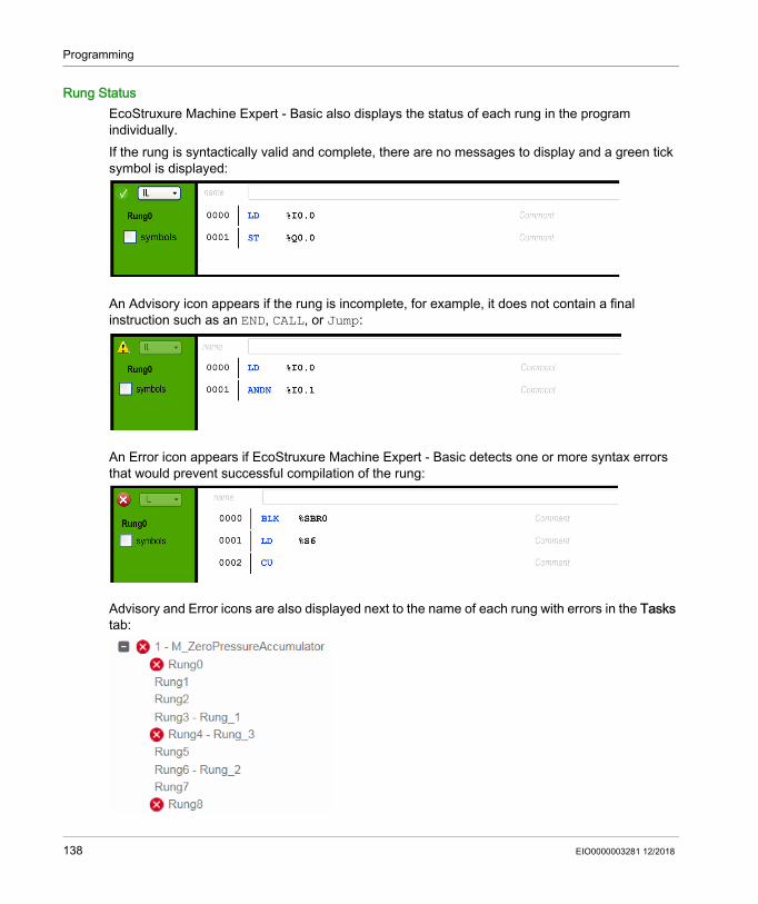
Programming
Rung StatusEcoStruxure Machine Expert - Basic also displays the status of each rung in the program individually. If the rung is syntactically valid and complete, there are no messages to display and a green tick symbol is displayed:
An Advisory icon appears if the rung is incomplete, for example, it does not contain a final instruction such as an END, CALL, or Jump:
An Error icon appears if EcoStruxure Machine Expert - Basic detects one or more syntax errors that would prevent successful compilation of the rung:
Advisory and Error icons are also displayed next to the name of each rung with errors in the Tasks tab:
138 EIO0000003281 12/2018

Programming
Animation Tables
OverviewYou can add objects to animation tables to: View symbols and comments associated with objects. View and modify the real-time values of certain object types when EcoStruxure Machine Expert
- Basic is connected to the logic controller (online mode). Select objects to be displayed in the Trace window (see page 226).Animation tables are a component of an EcoStruxure Machine Expert - Basic application, and so are downloaded to the logic controller as part of the non-program data together with the program. This allows the objects stored in animation tables to be retrieved when an application is later uploaded from the logic controller.
If you add an object that does not exist to an animation table, the Value field is displayed with a red outline. For example, if you add %Q1.0 but there is no corresponding digital output module in the configuration.
Creating an Animation Table
Step Action1 Select the Tools tab in the left-hand area of the Programming window.2 Right-click Animation tables and choose Add new animation table from the contextual menu that
appears.Result: A new animation table item appears below the Animation Tables area of the Tools window, and a properties window appears in the lower central area of the window.
EIO0000003281 12/2018 139
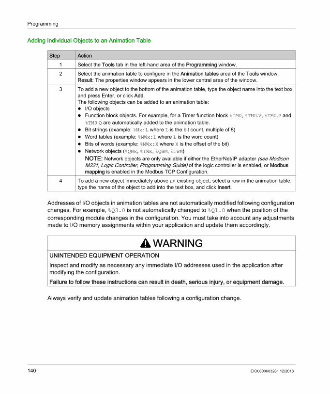
Programming
Adding Individual Objects to an Animation Table
Addresses of I/O objects in animation tables are not automatically modified following configuration changes. For example, %Q3.0 is not automatically changed to %Q1.0 when the position of the corresponding module changes in the configuration. You must take into account any adjustments made to I/O memory assignments within your application and update them accordingly.
Always verify and update animation tables following a configuration change.
Step Action1 Select the Tools tab in the left-hand area of the Programming window.2 Select the animation table to configure in the Animation tables area of the Tools window.
Result: The properties window appears in the lower central area of the window.3 To add a new object to the bottom of the animation table, type the object name into the text box
and press Enter, or click Add. The following objects can be added to an animation table: I/O objects Function block objects. For example, for a Timer function block %TM0, %TM0.V, %TM0.P and
%TM0.Q are automatically added to the animation table. Bit strings (example: %Mx:L where L is the bit count, multiple of 8) Word tables (example: %MWx:L where L is the word count) Bits of words (example: %MWx:X where X is the offset of the bit) Network objects (%QWE, %IWE, %QWM, %IWM)
NOTE: Network objects are only available if either the EtherNet/IP adapter (see Modicon M221, Logic Controller, Programming Guide) of the logic controller is enabled, or Modbus mapping is enabled in the Modbus TCP Configuration.
4 To add a new object immediately above an existing object, select a row in the animation table, type the name of the object to add into the text box, and click Insert.
WARNINGUNINTENDED EQUIPMENT OPERATIONInspect and modify as necessary any immediate I/O addresses used in the application after modifying the configuration.Failure to follow these instructions can result in death, serious injury, or equipment damage.
140 EIO0000003281 12/2018

Programming
Adding All Objects Used in a Rung to the Animation Table
NOTE:
The rung must contain no errors detected (error icon does not appear). Only the first 64 objects used in the rung are added (the maximum size of an animation table). If the same object appears more than once in a rung, only the first occurrence is added to the
animation table.
Animation Table PropertiesThis table describes the properties of the animation tables:
Step Action1 If more than 1 animation table exists, select an animation table in the Animation tables area of
the Tools window.Result: The animation table properties window appears in the lower central area of the window.
2 Select the Tasks window.3 Right-click a rung and choose Add rung objects to the current animation table from the contextual
menu that appears. Result: Objects used in the rung are added to the animation table.
Parameter Editable Value DescriptionUsed No True/False Indicates whether the object is currently being used in a program.Trace Yes(1) True/False Select the object to trace in the Trace window (see page 226).
Address No Object address Displays the address of the object.Symbol No A valid symbol The name of the symbol associated with this object, if defined.Value Yes(2) Current value The value of the object.
If the object type has read/write access and you are in online mode (see page 31), double-click and type a new object value if required. The value of the object is updated in real time in the program running in the logic controller. See Modifying Real-Time Values (see page 229) for details.
(1) You can select up to 8 objects.(2) Depending on the object type, and whether you are in online mode.
EIO0000003281 12/2018 141

Programming
Configuring Items in an Animation TableTo search for and optionally replace an object in an animation table, right-click the object and choose Search and Replace. Refer to Search and Replace (see page 157) for further details.To remove an object from an animation table, right-click the object and choose Remove from animation table.
Copying/Cutting and Pasting Existing Animation Tables
When you paste an animation table to a project with a lower functional level (see page 80), only the object configurations supported by this functional level are copied.If the symbols contained in the pasted animation table are already used in the project, EcoStruxure Machine Expert - Basic replaces the pasted symbol.
Force Yes(2) Force to 0Force to 1Not Forced
Only appears for digital inputs and digital outputs. Only editable when in online mode (see page 31). Allows you to force the value of the input or output to 0 or 1 as required.Choose Not Forced to remove any forcing currently applied to the address.
NOTE: Forcing is performed at the end of the scan cycle. The image table of the outputs, however, may be modified due to the logic of your program, and may appear in animation tables and other data displays contrary to the forced state you selected. At the end of the scan, this will be corrected by acting upon the requested forced state and the physical output will indeed reflect that forced state.
Comment No A valid comment The comment associated with this object, if defined.
Parameter Editable Value Description
(1) You can select up to 8 objects.(2) Depending on the object type, and whether you are in online mode.
Step Action1 Select the Tools tab in the left-hand area of the Programming window.2 Select one or more animation tables in Animation tables by pressing and holding the CTRL key.3 Right-click one of the selected animation tables in Animation tables and choose Copy animation
table or Cut animation table.4 To paste the animation table, either:
Right-click Animation tables and choose Paste animation table. Right-click an existing animation table and choose Paste animation table.
Result: The Confirmation window appears. To keep the symbols and comments, clear the check box, then click Ok.Result: One or more animation tables are added at the end of Animation tables or after the selected animation table.When copying/pasting an animation table, EcoStruxure Machine Expert - Basic automatically assigns a new name. For example: Animation_table_2 becomes Animation_table_2_0.
142 EIO0000003281 12/2018
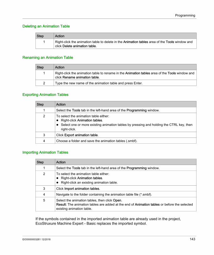
Programming
Deleting an Animation Table
Renaming an Animation Table
Exporting Animation Tables
Importing Animation Tables
If the symbols contained in the imported animation table are already used in the project, EcoStruxure Machine Expert - Basic replaces the imported symbol.
Step Action1 Right-click the animation table to delete in the Animation tables area of the Tools window and
click Delete animation table.
Step Action1 Right-click the animation table to rename in the Animation tables area of the Tools window and
click Rename animation table.2 Type the new name of the animation table and press Enter.
Step Action1 Select the Tools tab in the left-hand area of the Programming window.2 To select the animation table either:
Right-click Animation tables. Select one or more existing animation tables by pressing and holding the CTRL key, then
right-click.3 Click Export animation table.4 Choose a folder and save the animation tables (.smbf).
Step Action1 Select the Tools tab in the left-hand area of the Programming window.2 To select the animation table either:
Right-click Animation tables. Right-click an existing animation table.
3 Click Import animation tables.4 Navigate to the folder containing the animation table file (*.smbf).5 Select the animation tables, then click Open.
Result: The animation tables are added at the end of Animation tables or before the selected existing animation table.
EIO0000003281 12/2018 143

Programming
Opening the Trace Window
Step Action1 Select up to 8 objects in the Trace column of an animation table.2 Connect (see page 246) to the logic controller or launch the simulator (see page 264).3 Select a value in the Time Base list. This determines the refresh frequency of the Trace window
(see page 226), in seconds.4 Click Trace.
The Trace window is displayed.
144 EIO0000003281 12/2018

Programming
Memory Objects
OverviewMemory objects include: Memory bits Memory words Constant words
Selecting the Memory Allocation ModeBefore viewing or updating the properties of memory objects, choose the memory allocation mode (see page 70) to use.
Displaying the Used Memory ObjectsTo display the used memory objects, select the Table view check box.
Memory Bit PropertiesThis table describes each parameter of the Memory bits screen:
Memory Word Properties
First choose the memory word type to display properties for: %MW. Memory words %MD. Double words %MF. Floating-point words
Parameter Editable Value Default Value DescriptionUsed No True/False False Indicates whether the memory bit is currently
being used in a program.Address No Refer to Bit
ObjectsN/A Displays the address of the memory bit,
where x is the number of memory bits supported by the logic controller.
Symbol Yes A valid symbol None Allows you to associate a symbol with this memory bit.
Value Yes Refer to Bit Objects.
0 The value of this memory bit.
Comment Yes A valid comment None Allows you to associate a comment with this memory bit
EIO0000003281 12/2018 145
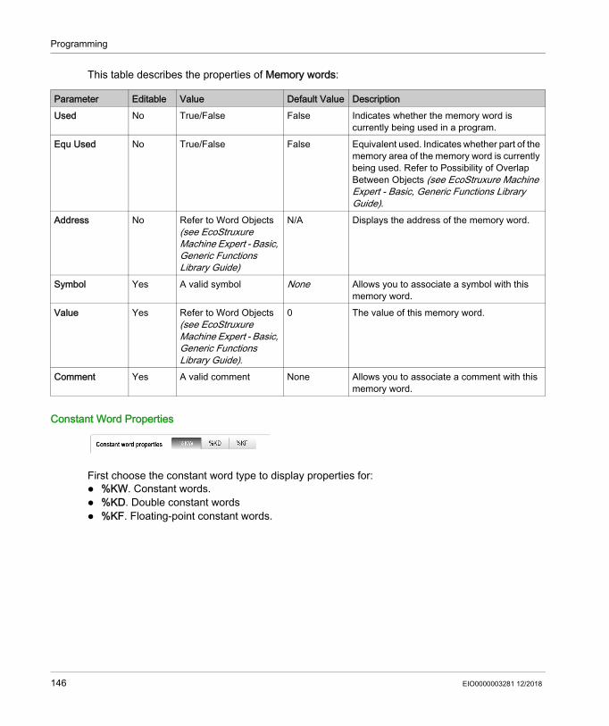
Programming
This table describes the properties of Memory words:
Constant Word Properties
First choose the constant word type to display properties for: %KW. Constant words. %KD. Double constant words %KF. Floating-point constant words.
Parameter Editable Value Default Value DescriptionUsed No True/False False Indicates whether the memory word is
currently being used in a program.Equ Used No True/False False Equivalent used. Indicates whether part of the
memory area of the memory word is currently being used. Refer to Possibility of Overlap Between Objects (see EcoStruxure Machine Expert - Basic, Generic Functions Library Guide).
Address No Refer to Word Objects (see EcoStruxure Machine Expert - Basic, Generic Functions Library Guide)
N/A Displays the address of the memory word.
Symbol Yes A valid symbol None Allows you to associate a symbol with this memory word.
Value Yes Refer to Word Objects (see EcoStruxure Machine Expert - Basic, Generic Functions Library Guide).
0 The value of this memory word.
Comment Yes A valid comment None Allows you to associate a comment with this memory word.
146 EIO0000003281 12/2018

Programming
This table describes each parameter of the Constant words screen:
Parameter Editable Value Default Value DescriptionUsed No True/False False Indicates whether the constant word is
currently being used in a program.Equ Used No True/False False Equivalent used. Indicates whether part of
the memory area of the constant word is currently being used. Refer to Possibility of Overlap Between Objects (see EcoStruxure Machine Expert - Basic, Generic Functions Library Guide).
Address No Refer to Word Objects (see EcoStruxure Machine Expert - Basic, Generic Functions Library Guide)
N/A Displays the address of the constant word.
Symbol Yes A valid symbol None Allows you to associate a symbol with this constant word.
Decimal Yes Decimal representation of the value. Refer to Word Objects (see EcoStruxure Machine Expert - Basic, Generic Functions Library Guide)
0 The decimal value of this constant word.
Binary Yes Binary representation of the value. Refer to Word Objects (see EcoStruxure Machine Expert - Basic, Generic Functions Library Guide)
2#0000000000000000 The binary value of this constant word.
Hexadecimal Yes Hexadecimal representation of the value. Refer to Word Objects (see EcoStruxure Machine Expert - Basic, Generic Functions Library Guide)
16#0000 The hexadecimal value of this constant word.
EIO0000003281 12/2018 147

Programming
Exporting/Importing the Constant Word PropertiesYou can export into a CSV file and import the Address, Symbol, Value, and Comment properties in offline or online mode.Exporting the constant word properties:
ASCII Yes ASCII representation of the value. Refer to Word Objects (see EcoStruxure Machine Expert - Basic, Generic Functions Library Guide)
no meaning The ASCII value of this constant word.
Comment Yes A valid comment None Allows you to associate a comment with this constant word.
Parameter Editable Value Default Value Description
Step Action1 Select the Tools tab in the left-hand area of the Programming window.2 Click Memory objects → Constant words.3 In Constant word properties, click Export.
Result: The Export constants window appears.4 In the Export constants window:
1. Select the Export type.
2. Choose the File path by clicking .3. Enter: The File name, The First index (numeric), The Last index (numeric).
The First index must be less than or equal to the Last Index.5
To modify the export parameters, click Export options:1. Select Headers if you want to display the name of the headers.2. Choose Semicolon or Comma as separator.
6 Click Export.
148 EIO0000003281 12/2018

Programming
Importing the constant word properties:
In case of duplicate values, the last duplicate value is imported.
Step Action1 Select the Tools tab in the left-hand area of the Programming window.2 Click Memory objects → Constant words.3 In Constant word properties, click Import.
Result: The window Import constants appears.4
Click and navigate to the folder containing the file (*.csv) and double-click the file.5
To modify the import parameters, click Import options and choose the separator used in the .csv file: Semicolon or Comma.
6 Click Import.
EIO0000003281 12/2018 149

Programming
System Objects
OverviewSystem objects are specific to the logic controller. For details, refer to the Programming Guide of your logic controller.
150 EIO0000003281 12/2018

Programming
I/O Objects
OverviewThe following object types are hardware-specific and depend on the logic controller being used: Digital inputs and outputs Analog inputs and outputs Advanced function blocks such as fast counters, high-speed counters, and pulse generators. For more details, refer to the Programming Guide and Advanced Functions Library Guide of your logic controller.
EIO0000003281 12/2018 151

Programming
Network Objects
PresentationNetwork objects are used to communicate via EtherNet/IP, Modbus TCP, or Modbus Serial IOScanner.There are two types of network object for EtherNet/IP communication: %QWE: Input Assembly %IWE: Output Assembly
There are two types of network object for Modbus TCP communication: %QWM: Input registers %IWM: Output registers
The following types of network object are used for the Modbus Serial IOScanner: %IN: Digital inputs (IOScanner) %QN: Digital outputs (IOScanner) %IWN: Input registers (IOScanner) %QWN: Output registers (IOScanner) %IWNS: IOScanner Network Diagnostic Codes
NOTE: References to input and output are from the point of view of the EtherNet/IP master or Modbus TCP client.For more information on how to configure network objects, refer to the programming guide for your logic controller.
152 EIO0000003281 12/2018
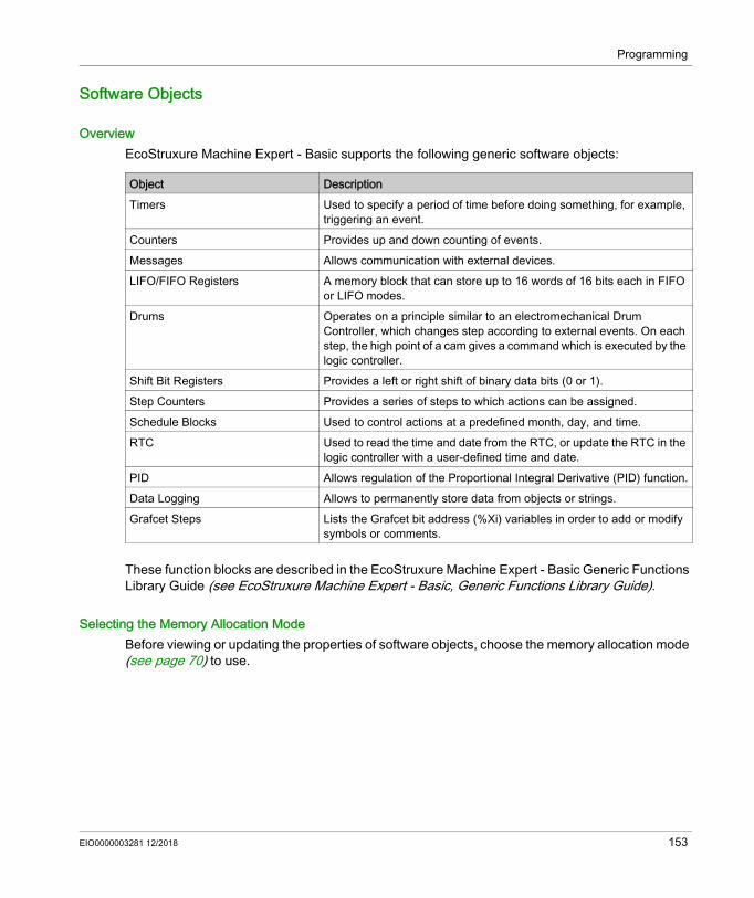
Programming
Software Objects
OverviewEcoStruxure Machine Expert - Basic supports the following generic software objects:
These function blocks are described in the EcoStruxure Machine Expert - Basic Generic Functions Library Guide (see EcoStruxure Machine Expert - Basic, Generic Functions Library Guide).
Selecting the Memory Allocation ModeBefore viewing or updating the properties of software objects, choose the memory allocation mode (see page 70) to use.
Object DescriptionTimers Used to specify a period of time before doing something, for example,
triggering an event.Counters Provides up and down counting of events. Messages Allows communication with external devices. LIFO/FIFO Registers A memory block that can store up to 16 words of 16 bits each in FIFO
or LIFO modes.Drums Operates on a principle similar to an electromechanical Drum
Controller, which changes step according to external events. On each step, the high point of a cam gives a command which is executed by the logic controller.
Shift Bit Registers Provides a left or right shift of binary data bits (0 or 1).Step Counters Provides a series of steps to which actions can be assigned.Schedule Blocks Used to control actions at a predefined month, day, and time.RTC Used to read the time and date from the RTC, or update the RTC in the
logic controller with a user-defined time and date.PID Allows regulation of the Proportional Integral Derivative (PID) function.Data Logging Allows to permanently store data from objects or strings.Grafcet Steps Lists the Grafcet bit address (%Xi) variables in order to add or modify
symbols or comments.
EIO0000003281 12/2018 153

Programming
PTO Objects
OverviewThe PTO objects provide the function blocks used for programming the PTO functions. The PTO function blocks are categorized as: Motion task tables
Allows you to configure individual PTO movements in an ordered sequence, and visualize an estimated global movement profile.
MotionThese function blocks control motions of the axis. For example, power to axis, movement of the axis, and so on.
AdministrativeThese function blocks control the status and diagnostics of the axis movement. For example, status and value of actual velocity, actual position, axis control detected errors, and so on.
For more details on the PTO function blocks, refer to the Advanced Function Library Guide of your controller.
154 EIO0000003281 12/2018
Programming
Drive Objects
OverviewDrive objects control ATV drives and other devices configured on the Modbus Serial IOScanner or Modbus TCP IOScanner. Refer to the Advanced Functions Library Guide of your logic controller.
EIO0000003281 12/2018 155
Programming
Communication Objects
OverviewCommunication objects are used to communicate with Modbus devices, send/receive messages in character mode (ASCII), and to send/receive SMS messages.For details, refer to the chapter Communication Objects.
156 EIO0000003281 12/2018

Programming
Search and Replace
OverviewSearch and Replace allows you to find all occurrences of an object used anywhere in a program and optionally replace it with a different object.
Searching and Replacing Items
Step Action1 Select the Tools tab in the left-hand area of the Programming window.
It is also possible to invoke the search and replace function from various other locations in EcoStruxure Machine Expert - Basic, for example, by right-clicking on an entry in an animation table (see page 139) and selecting Search & Replace.
2 You can use any of the following methods to display the Search and Replace window: Click Search and Replace in the Tools tab of the Programming window. Right-click on a rung or a selected item in the rung and click Search and Replace in the
context menu that appears. Right-click on a line in the properties window of any object and click Search and Replace in
the context menu that appears.This graphic shows the Search and Replace window:
3 In the Find box type the object or symbol name to find. The Find field is pre-filled if the search was started by right-clicking on a selected item in a rung or an item in a properties window of an object.)You can use the following wildcard characters: Asterisk (*). Replaces 0 or more characters in the search term. For example, %MW1* would
find both %MW1 and %MW101. Question mark (?). Replaces exactly 1 character in the search term. For example, typing
COIL?2 would find COIL12 but not COIL012
4 Optionally, in the Replace box type a replacement object or symbol name.5 Select Program to search for the item within the source code of the current program.
Select Comments to search for the item within program comments.
EIO0000003281 12/2018 157

Programming
6 Click Search or Replace. You can also press ENTER to start the search.Replace button is enabled only when the replacement object or symbol name is given in the Replace box.All items found are listed in the Results list:
7 Optionally, select Show symbols to display instead any symbols defined for objects:
8 Click on any of the listed results to jump directly to the line of code in the program.
Step Action
158 EIO0000003281 12/2018

Programming
Cross Reference
OverviewThe cross reference view allows to display the program contained in a POU. If an object depends on another object of the same POU, the corresponding rungs are displayed.The cross reference view is available in both offline and online modes.
Displaying the Cross Reference ViewTo display the cross reference view, click Programming → Tools → Cross Reference, then select one or several objects in the action zone.
Cross Reference View
The following table presents the element of the cross reference view:
Element DescriptionPOU Name of the POU containing the object.Rung Name of the rung containing the object.Code view Programming code of the object.Symbol view Symbol of the object.
EIO0000003281 12/2018 159

Programming
Symbol List
OverviewYou can display a list of all the symbols that have been associated with objects in your program. All objects with symbols are displayed, with the exception of symbols automatically associated with system bits (%S) and system words (%SW). You can overwrite symbols and comments on system bits (%S) and system words (%SW) using the System Objects properties, or by importing your own symbols list (see below). Overwritten symbols then appear in the symbol list.Defining and Using Symbols (see page 68) describes how to create symbols and use them in your programs.
Displaying the Symbol List
Creating Default SymbolsTo create default symbols for memory objects:1. Click Assign symbol.
Result: Default symbols are assigned to all memory objects (%M, %MW, %MD, %MF, %S, %SW, %KW, %KD, %KF, %I, %IW, %Q, %QW) used in the program that do not already have symbols defined.Symbols are named as follows: symbolname = objectname_i, where objectname is the object type without the % and i is the index of the object.
Example: The following objects are used in the program but have no symbols defined:
Step Action1 Select the Tools tab in the left-hand area of the Programming window.2 Click Symbol list.
Result: The Symbol list window is displayed. For each item the following information is displayed: Used: Whether the symbol is currently being used in the program. Address: The address of the object with which the symbol is associated. Symbol: The symbol name. Comment: The comment associated with this object, if defined. Assign symbol: EcoStruxure Machine Expert - Basic automatically assigns a symbol to each
object used without symbol of the following types: %M, %MW, %MD, %MF, %S, %SW, %KW, %I, %IW, %Q, and %QW.
Delete default symbols: Deleting default symbols assigned. Import: Importing symbols. Export: Exporting symbols.
Object Symbol Assigned%MW0 MW_0
%MW2 MW_2
%M0 M_0
160 EIO0000003281 12/2018
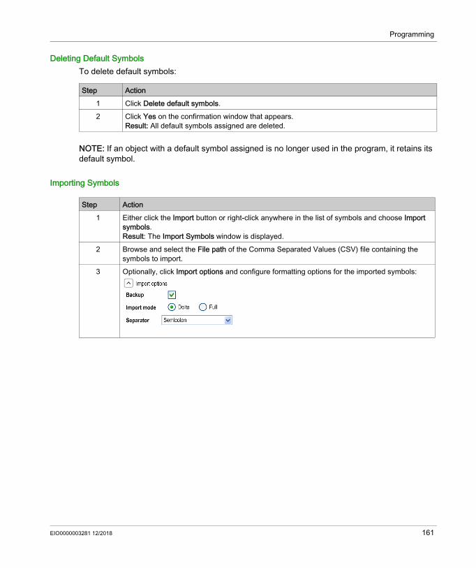
Programming
Deleting Default SymbolsTo delete default symbols:
NOTE: If an object with a default symbol assigned is no longer used in the program, it retains its default symbol.
Importing Symbols
Step Action1 Click Delete default symbols.2 Click Yes on the confirmation window that appears.
Result: All default symbols assigned are deleted.
Step Action1 Either click the Import button or right-click anywhere in the list of symbols and choose Import
symbols.Result: The Import Symbols window is displayed.
2 Browse and select the File path of the Comma Separated Values (CSV) file containing the symbols to import.
3 Optionally, click Import options and configure formatting options for the imported symbols:
EIO0000003281 12/2018 161

Programming
Exporting the Symbol List
4 Click Import. Result: All symbols in the selected CSV file are created and displayed in the Symbol list window with the specified formatting options.If errors are detected during import, a report is displayed listing them:
5 Click Save to write the contents of the report to a plain text (.txt) file.
Step Action
Step Action1 Either click the Export button or right-click anywhere in the list of symbols and choose Export
symbols You are prompted to save changes.The Export Symbols window is displayed.
2 Browse and select the File path and File name of the Comma Separated Values (CSV) file to be created.
3 Optionally, click Export options and configure formatting options for the exported values:
4 Click Export. Result: A CSV file is created with the specified formatting options.
162 EIO0000003281 12/2018

Programming
Sharing Symbols Between an EcoStruxure Machine Expert - Basic Project and an Vijeo-Designer ProjectBefore sharing the symbols with a Vijeo-Designer project, verify that all symbols that you want to share are defined in the EcoStruxure Machine Expert - Basic project. If not, create/open a project in EcoStruxure Machine Expert - Basic, define the symbol names, and save the project. You can create default Vijeo-Designer symbols for all memory objects in the project, refer to Creating Default Symbols (see page 160).Follow these steps to share EcoStruxure Machine Expert - Basic symbols with a Vijeo-Designer project:
NOTE: If you have already shared the symbols with a Vijeo-Designer project before and if you change the existing symbols and/or add new symbols to your project in EcoStruxure Machine Expert - Basic, you must update the symbols in the Vijeo-Designer project.
Step Action1 Start Vijeo-Designer.2 Create/open a project in Vijeo-Designer.3 Click the Project tab in the Navigator window, right-click IO Manager and select New Driver...
Insert.Result: The New Driver window opens.
4 Select a driver from the Driver list, select an equipment from the Equipment list, and click OK.For example: Driver: Modbus TCP/IP Equipment: Modbus Equipment
Result: The Equipment Configuration window opens.5 Enter the details for each parameter and click OK. For example, IP Address, Unit ID, IP Protocol,
and so on.Result: A new driver is created to open the communication with the controller. The selected driver and the selected equipment appear under the IO Manager node in the Project tab of the Navigator window.
6 In the Vijeo-Designer menu bar, click Variable → Link Variables.Result: The Link Variable window opens.
7 Select the Files of type filter to Ecostruxure Machine Expert - Basic project files (*.SMBP) and select the Equipment filter to the driver that you have created for communication.
8 Select the EcoStruxure Machine Expert - Basic project in which you have defined the symbols and click Open.Result: All the symbols are automatically extracted from the project and linked to the driver that you have created.
9 Select the variables that you want to use and add them to your HMI application.Result: All the variables with same names as symbols are added in the list of available variables. The variable list appears under the Variables node in the Project tab of the Navigator window.
EIO0000003281 12/2018 163

Programming
To update the symbols in a Vijeo-Designer project, first define new symbols and/or modify the existing symbols, save the EcoStruxure Machine Expert - Basic project, and open the Vijeo-Designer project and follow these steps:
Step Action1 In the Project tab of the Navigator window, right-click Variables and select Update Link.
Result: The equipment driver and the existing symbols are updated.2 Right-click Variables again, select New Variables from Equipment and select the new variables
that you have created in the EcoStruxure Machine Expert - Basic project.Result: The new variables from the EcoStruxure Machine Expert - Basic project are added in the list of variables. These variables appear under the Variables node in the Project tab of the Navigator window.
164 EIO0000003281 12/2018

Programming
Memory Consumption View
OverviewYou can display information about the controller memory used by the application, program, and associated user data.
Displaying the Memory Consumption ViewThe program must first compile with no errors detected to use this feature. Refer to the Messages window (see page 137) for the current program status.To open the Memory consumption view, follow this procedure:
Description of the Memory Consumption ViewNOTE: This view is available only if there is a valid compilation.The following tables describe the fields of the Memory consumption view:
Step Action1 Select the Tools tab in the left-hand area of the Programming window.2 Click Memory Consumption.
The Memory Consumption window is displayed.
Field DescriptionLast Compilation The date and time on which the program was last compiled.
NOTE: This value is updated whenever:
the Compile button on the toolbar is clicked a login to a controller is initiated a program upload is started a program modification is sent to the controller in online mode the simulator is launched
Program linesField DescriptionUsed The number of lines of code being used by the program.Remaining The maximum number of lines available for the program minus the number of lines
being used.
NOTE: There is no direct link between the number of program lines used and the total number of lines of IL code in rungs in the Programming tab. For example, 2 lines of IL code could generate 6 program lines.
EIO0000003281 12/2018 165
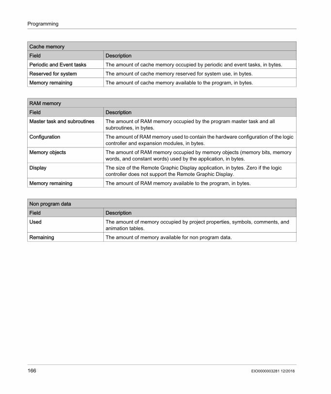
Programming
Cache memoryField DescriptionPeriodic and Event tasks The amount of cache memory occupied by periodic and event tasks, in bytes.Reserved for system The amount of cache memory reserved for system use, in bytes.Memory remaining The amount of cache memory available to the program, in bytes.
RAM memoryField DescriptionMaster task and subroutines The amount of RAM memory occupied by the program master task and all
subroutines, in bytes.Configuration The amount of RAM memory used to contain the hardware configuration of the logic
controller and expansion modules, in bytes.Memory objects The amount of RAM memory occupied by memory objects (memory bits, memory
words, and constant words) used by the application, in bytes.Display The size of the Remote Graphic Display application, in bytes. Zero if the logic
controller does not support the Remote Graphic Display.Memory remaining The amount of RAM memory available to the program, in bytes.
Non program dataField DescriptionUsed The amount of memory occupied by project properties, symbols, comments, and
animation tables.Remaining The amount of memory available for non program data.
166 EIO0000003281 12/2018

Programming
Ladder Language Programming
Section 5.12Ladder Language Programming
What Is in This Section?This section contains the following topics:
Topic PageIntroduction to Ladder Diagrams 168Programming Principles for Ladder Diagrams 170Color Coding of Rungs 172Ladder Diagram Graphic Elements 174Comparison Blocks 181Operation Blocks 182Adding Comments 186Programming Best Practices 187
EIO0000003281 12/2018 167

Programming
Introduction to Ladder Diagrams
IntroductionLadder Diagrams are similar to relay logic diagrams that represent relay control circuits. The main differences between the 2 are the following features of Ladder Diagram programming that are not found in relay logic diagrams:
All inputs and binary logic bits are represented by contact symbols ( ).
All outputs and binary logic bits are represented by coil symbols ( ). Numerical operations are included in the graphical Ladder instruction set.
Ladder Diagram Equivalents to Relay CircuitsThe following illustration shows a simplified wiring diagram of a relay logic circuit:
The equivalent Ladder diagram:
In the above illustration, all inputs associated with a switching device in the relay logic diagram are shown as contacts in the Ladder Diagram. The M1 output coil in the relay logic diagram is represented with an output coil symbol in the Ladder Diagram. The address numbers appearing above each contact/coil symbol in the Ladder Diagram are references to the locations of the external input/output connections to the logic controller.
168 EIO0000003281 12/2018

Programming
Ladder Diagram RungsA program written in Ladder Diagram language is composed of rungs which are sets of graphical instructions drawn between 2 vertical potential bars. The rungs are executed sequentially by the logic controller.The set of graphical instructions represents the following functions: Inputs/outputs of the controller (push buttons, sensors, relays, pilot lights, and so on) Functions of the controller (timers, counters, and so on) Math and logic operations (addition, division, AND, XOR, and so on) Comparison operators and other numerical operations (A<B, A=B, shift, rotate, and so on) Internal variables in the controller (bits, words, and so on)These graphical instructions are arranged with vertical and horizontal connections leading eventually to one or several outputs and/or actions. A rung cannot support more than one group of linked instructions.
Example of Ladder Diagram RungsThe following diagram is an example of a Ladder Diagram program composed of 2 rungs.
EIO0000003281 12/2018 169
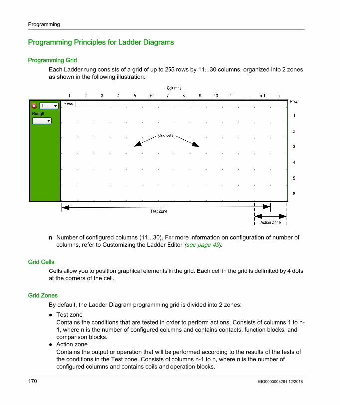
Programming
Programming Principles for Ladder Diagrams
Programming GridEach Ladder rung consists of a grid of up to 255 rows by 11...30 columns, organized into 2 zones as shown in the following illustration:
n Number of configured columns (11...30). For more information on configuration of number of columns, refer to Customizing the Ladder Editor (see page 49).
Grid CellsCells allow you to position graphical elements in the grid. Each cell in the grid is delimited by 4 dots at the corners of the cell.
Grid ZonesBy default, the Ladder Diagram programming grid is divided into 2 zones: Test zone
Contains the conditions that are tested in order to perform actions. Consists of columns 1 to n-1, where n is the number of configured columns and contains contacts, function blocks, and comparison blocks.
Action zoneContains the output or operation that will be performed according to the results of the tests of the conditions in the Test zone. Consists of columns n-1 to n, where n is the number of configured columns and contains coils and operation blocks.
170 EIO0000003281 12/2018

Programming
Customizing the Ladder Editor
Use the following objects at the top of the Ladder editor to customize the content of the editor:
Object DescriptionIL>LD Switch from displaying all rungs in IL to Ladder.LD>IL Switch from displaying all rungs in Ladder to IL.- Delete one column from the Ladder grid. The button is deactivated when the minimum
number of columns (11) is reached.+ Add one column to the Ladder grid. The button is deactivated when the maximum
number of columns (30) is reached.Display/hide comments
Click to display or hide comments in the rungs.If T is released, the comments display on two lines.
T Click to display or hide the symbols in the rungs. If Display/hide comments is released, the symbols are displayed on two lines.
DEC/HEX Only displayed in online mode. Click to display alternately numerical values in the rungs in decimal or hexadecimal format.
1 - New POU Double-click to edit the default POU name that appears in the Tools → Master Task area of the screen.
Comment Double-click to type text to associate a comment with this POU.Zoom slider Zoom or unzoom the Ladder Editor.
You can zoom or unzoom by using the shortcut Ctrl + mouse wheel.The position of the zoom remains even if you navigate through the project.
EIO0000003281 12/2018 171

Programming
Color Coding of Rungs
Offine ModeThe selected rungs are displayed in a darker green background:
172 EIO0000003281 12/2018

Programming
Online ModeWhen in online mode: Unchanged rungs appear with a green background. Rungs added or modified while in online mode appear with an orange background:
Rungs with no modifiable elements are locked and appear with a gray foreground:
EIO0000003281 12/2018 173

Programming
Ladder Diagram Graphic Elements
IntroductionInstructions in Ladder Diagrams are inserted by dragging and dropping graphic elements from the toolbar that appears above the programming workspace into a grid cell.
Inserting a Graphic ElementTo insert a graphic element in a rung:
RungsUse the following graphic elements to manage the rungs in a program:
Step Action1 Click the graphic element on the toolbar to insert. If the graphic element is a menu, the graphic
items in the menu appear; click the menu item to insert.2 Move the mouse to the position in the rung to insert the graphic element and click.
Note: Some elements have to be inserted in the test or action zones of the rung; refer to the description of individual graphic elements for details.
3
If necessary, click the [Selection mode] graphic element on the toolbar to reset the selection.
Graphic Element
Name Function
Create a rung (see page 90)
Inserts a new empty rung below the last rung in the program workspace.
Insert a rung (see page 90)
Inserts a new empty rung immediately above the currently selected rung.
Delete the rung (see page 92)
Removes the currently selected rung from the program. If the rung is not empty, you are asked to confirm that you want to delete the contents of the rung.
174 EIO0000003281 12/2018

Programming
Branching ModesUse the following graphic elements to manage the branch in Ladder diagram:
Selections and LinesUse the following graphic elements to select graphic elements and draw lines:
ContactsUse the following graphic elements to insert contacts (one row high by one column wide).
Graphic Element
Name Function
Normal mode Lets you place the programming elements (for example, contacts, coils, and so on, except the function blocks) inline with the wire line.
Branching mode Lets you place the programming elements (for example, contacts, coils, and so on, except the function blocks) in branch with the wire line.
Graphic Element
Name Function
Selection mode Selection mode.
Draw line Draws a wire line between 2 graphic elements.
Erase line Erases a wire line.
Graphic Element
Name Instruction List
Function
Normally open contact LD Passing contact when the controlling bit object is at state 1.
Normally closed contact
LDN Passing contact when the controlling bit object is at state 0.
Contact for detecting a rising edge
LDR Rising edge: detecting the change from 0 to 1 of the controlling bit object.
Contact for detecting a falling edge
LDF Falling edge: detecting the change from 1 to 0 of the controlling bit object.
EIO0000003281 12/2018 175
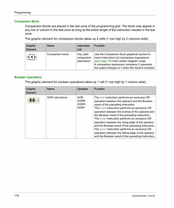
Programming
Comparison BlockComparison blocks are placed in the test zone of the programming grid. The block may appear in any row or column in the test zone as long as the entire length of the instruction resides in the test zone.The graphic element for comparison blocks takes up 2 cells (1 row high by 2 columns wide).
Boolean OperationsThe graphic element for boolean operations takes up 1 cell (1 row high by 1 column wide).
Graphic Element
Name Instruction List
Function
Comparison block Any valid comparison expression
Use the Comparison block graphical symbol to insert Instruction List comparison expressions (see page 181) into Ladder Diagram rungs. A comparison expression compares 2 operands; the output changes to 1 when the result is checked.
Graphic Element
Name Operator Function
XOR instructions XOR, XORN, XORR, XORF
The XOR instruction performs an exclusive OR operation between the operand and the Boolean result of the preceding instruction.The XORN instruction performs an exclusive OR operation between the inverse of the operand and the Boolean result of the preceding instruction.The XORR instruction performs an exclusive OR operation between the rising edge of the operand and the Boolean result of the preceding instruction.The XORF instruction performs an exclusive OR operation between the falling edge of the operand and the Boolean result of the preceding instruction.
176 EIO0000003281 12/2018

Programming
FunctionsFunction blocks always appear in the first row of the Ladder Diagram programming grid; no Ladder instructions or lines of continuity may appear above or below the function block. Ladder test instructions lead to the left side of the function block, and test instructions and action instructions lead from the right side of the function.The graphic elements of function blocks can only be placed in the test zone and require 2, 3, or 4 rows by 2 columns of cells.
CoilsThe coil graphic elements can only be placed in the action zone and take up 1 cell (1 row high and 1 column wide).
Graphic Element
Name Function
Timers, counters, registers, and so on.
Each of the function blocks uses inputs and outputs that enable links to the other graphic elements.
NOTE: Outputs of function blocks cannot be connected to each other (vertical shorts).
Graphic Element
Name Operator Function
Direct coil ST The associated bit object takes the value of the test zone result.
Inverse coil STN The associated bit object takes the negated value of the test zone result.
Set coil S The associated bit object is set to 1 when the result of the test zone is 1.
Reset coil R The associated bit object is set to 0 when the result of the test zone is 1.
EIO0000003281 12/2018 177

Programming
Grafcet (List) InstructionsUse the following graphic elements to manage the branch in Ladder diagram:
Operation BlocksThe operation block element placed in the action zone and occupy 2 columns by 1 row:
Other Ladder Items
The Other Ladder Items menu groups together miscellaneous instructions.The OPEN and SHORT instructions provide a convenient method for debugging and troubleshooting Ladder programs. These special instructions alter the logic of a rung by either shorting or opening the continuity of a rung as explained in the following table. The END/JUMP graphic elements are placed in the action zone and take up 1 cell (1 row high and 1 column wide).
Graphic Element
Name Operator Function
Grafcet step activation/Current step deactivation
# Deactivates the current step and optionally activates another step in the Grafcet program.
Grafcet step deactivation #D Deactivates a step in the Grafcet program in addition to deactivating the current step.
Graphic Element
Name Operator Function
Operation block Any valid operator or assignment instruction
Use the Operation block graphical symbol to insert Instruction List operations and assignment instructions (see page 182) into Ladder Diagram rungs.
Graphic Element
Name Operator Function
Rising edge RISING n (1) Evaluates the rising edge of the expression.
Falling edge FALLING n (1) Evaluates the falling edge of the expression.
Logical NOT N Passes the inverse value of its operand.
(1) n is an integer incremented each time a rising or falling edge is inserted.
178 EIO0000003281 12/2018

Programming
OPEN LD 0AND 0
At the beginning of the rung.Within a rung: Creates a break in the continuity of a Ladder rung regardless of the results of the last logical operation.
SHORT LD 1OR 1
At the beginning of the rung.Within a rung: Allows the continuity to pass through the rung regardless of the results of the last logical operation.
Stop program END Defines the end of the program.
Conditional stop program
ENDCN Defines a conditional end of the program.
Jump or subroutine call
JMP Connect to an upstream or downstream labeled rung.
NOTE: When programming in IL, connection is to an upstream or downstream labeled instruction.
Conditional jump or subroutine call
JMPCN Conditional connect to an upstream or downstream labeled rung.
NOTE: When programming in IL, connection is to an upstream or downstream labeled instruction.
Conditional elements
IFELSEENDIF
Conditionally executes a group of statements, depending on the value of an expression.
Loop elements FORENDFOR
Repeats a group of statements.
Graphic Element
Name Operator Function
(1) n is an integer incremented each time a rising or falling edge is inserted.
EIO0000003281 12/2018 179

Programming
Contacts and CoilsOnce inserted in a cell, additional information is displayed about the object associated with contacts and coils:
Legend Item Description1 User comment Click to add a comment (see page 186).2 Symbol Click to type the name of a symbol (see page 68) to associate with
the object contained in the cell.3 Address Click to type the address of the object contained in the cell. 4 Graphic element The graphic element.5 Real-time value When in online mode (connected to a logic controller and program
running), displays the real-time value of the object in the cell.
180 EIO0000003281 12/2018

Programming
Comparison Blocks
Inserting IL Comparison Expressions in Ladder DiagramsYou can use the Comparison Block graphical symbol to insert Instruction List comparison expressions into Ladder Diagram rungs:
The operands must be of the same object types: words with words, float with float, etc.Proceed as follows:
NOTE: If the application is configured with a functional level (see page 80) of at least Level 6.0: You can use up to five operands and three level of parentheses in a comparison block. A minimum of 20 memory words (%MW) must be available to use multiple operands in the master
task. If using multiple operands in a periodic task as well, an additional 20 memory words must be available.
NOTE: Multiple operand expressions cannot be used in event tasks.
Getting Help with SyntaxIf the syntax of the Instruction List comparison operation is incorrect, the border of the Comparison expression box turns red. For assistance, either: Move the mouse over the Comparison expression line, or Select Tools → Program Messages.
Step Action1
Click the Comparison Block button on the toolbar.2 Click anywhere in the rung to insert the Comparison Block.3 Double-click the Comparison expression line.4 Type a valid Instruction List comparison operation and press ENTER.
You can modify the expression in online mode. Refer to Online Modifications (see page 235).
EIO0000003281 12/2018 181

Programming
Operation Blocks
Inserting IL Operations and Assignment Instructions in Ladder DiagramsYou can use the Operation Block graphical symbol to insert Instruction List operations and assignment instructions into Ladder Diagram rungs:
The Operation Block graphical symbol can be inserted in any position in a Ladder Diagram rung except the first column, as it cannot be used as the first contact in a rung.If more than one Operation Block graphical symbol is used in a Ladder Diagram rung, they must be placed in series. Operation Block instructions cannot be used in parallel.NOTE: If the application is configured with a functional level (see page 80) of at least Level 5.0: You can use up to five operands and three levels of parentheses in a operation block. The
operands must be of the same object types: words with words, float with float, etc. A minimum of 20 memory words (%MW) must be available to use multiple operands in the master
task. If using multiple operands in a periodic task as well, an additional 20 memory words must be available.
To insert an operation block graphical symbol in a Ladder Diagram rung:
NOTE: Multiple operand expressions cannot be used in event tasks.
Operation block at the end of a rung. Operation block anywhere in a rung.
Step Action1
Click the Operation Block button on the toolbar.2 Click anywhere the rung to insert the Operation Block.3
Click the Selection mode button on the toolbar.4 Double-click the operation expression line.
The Smart Coding (see page 183) button appears at the end of the line. Click this button for help selecting a function and with the syntax of the instruction.
5 Type a valid Instruction List operation or assignment instruction and press ENTER.For example: %MF10 := ((SIN( %MF12 + 60.0 ) + COS( %MF13 )) + %MF10 ) + 1.2You can modify the expression in online mode. Refer to Online Modifications (see page 235).
182 EIO0000003281 12/2018
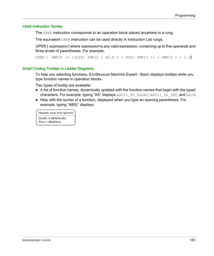
Programming
OPER Instruction SyntaxThe OPER instruction corresponds to an operation block placed anywhere in a rung.
The equivalent OPER instruction can be used directly in Instruction List rungs.
OPER [ expression ] where expression is any valid expression, containing up to five operands and three levels of parentheses. For example:OPER [ %MF10 := ((SIN( %MF12 + 60.0 ) + COS( %MF13 )) + %MF10 ) + 1.2]
Smart Coding Tooltips in Ladder DiagramsTo help you selecting functions, EcoStruxure Machine Expert - Basic displays tooltips while you type function names in operation blocks. Two types of tooltip are available: A list of function names, dynamically updated with the function names that begin with the typed
characters. For example, typing “AS” displays ASCII_TO_FLOAT, ASCII_TO_INT, and ASIN. Help with the syntax of a function, displayed when you type an opening parenthesis. For
example, typing “ABS(“ displays:
EIO0000003281 12/2018 183
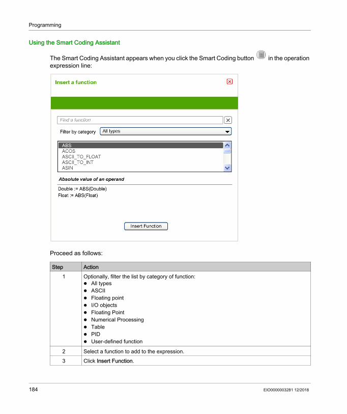
Programming
Using the Smart Coding Assistant
The Smart Coding Assistant appears when you click the Smart Coding button in the operation expression line:
Proceed as follows:
Step Action1 Optionally, filter the list by category of function:
All types ASCII Floating point I/O objects Floating Point Numerical Processing Table PID User-defined function
2 Select a function to add to the expression.3 Click Insert Function.
184 EIO0000003281 12/2018

Programming
Getting Help with SyntaxIf the syntax of the Instruction List operation or assignment instruction is incorrect, the border of the operation expression box turns red. For assistance, either: Move the mouse over the operation expression line, or Select Tools → Program Messages.
EIO0000003281 12/2018 185

Programming
Adding Comments
To Add Comments to Ladder DiagramsTo add comments to a Ladder Diagram program, follow these steps:
Example of Ladder Diagram CommentsThis illustration shows an example of comments in a rung of a Ladder Diagram:
Step Action1 Insert a graphic element into the rung.2 If necessary, click the selection pointer or press Esc. 3 Double-click the Comment line at the top of the graphic element.4 Type the comment for the graphic element and press ENTER.
186 EIO0000003281 12/2018

Programming
Programming Best Practices
Handling Program JumpsUse program jumps with care to avoid long loops that can increase scan time. Avoid jumps to instructions that are located upstream.NOTE: An upstream instruction line appears before a jump in a program. A downstream instruction line appears after a jump in a program.
Programming of OutputsPhysical outputs, as well as logical bits, should only be modified once in the program. In the case of physical outputs, only the last value scanned is taken into account when they are updated.
Using Directly-Wired Emergency Stop SensorsSensors used directly for emergency stops must not be processed by the logic controller. They must be connected directly to the corresponding outputs and applied in conformity with local, national and/or international regulations.
Handling Power ReturnsAfter a power outage, make power returns conditional on a manual operation. An automatic restart of the installation could cause unintended operation of equipment (use system bits %S0, %S1, and %S49). Other system bits and system words may also help manage restarts after power outages. Refer to System Bits (%S) and System Words (%SW) (see Modicon M221, Logic Controller, Programming Guide).
Time and Schedule Block ManagementThe state of system bit %S51, which indicates any detected RTC errors, should be verified.
Syntax ValidationAs you are programming, EcoStruxure Machine Expert - Basic validates the syntax of the instructions, the operands, and their associations.
WARNINGUNINTENDED EQUIPMENT OPERATION Do not use the equipment configured and programmed by this software in safety-critical machine functions, unless the equipment and software are otherwise designated as functional safety equipment and conforming to applicable regulations and standards.Failure to follow these instructions can result in death, serious injury, or equipment damage.
EIO0000003281 12/2018 187

Programming
Additional Notes on Using ParenthesesDo not place assignment instructions within parentheses:
The equivalent Ladder Diagram produces a short circuit error:
In order to perform the same function, program the instructions in the following manner:
188 EIO0000003281 12/2018

Programming
The equivalent Ladder Diagram:
If several contacts are in parallel, nest them within each other:
Alternatively, completely separate the contacts as follows:
EIO0000003281 12/2018 189

Programming
Instruction List Programming
Section 5.13Instruction List Programming
What Is in This Section?This section contains the following topics:
Topic PageOverview of Instruction List Programs 191Operation of List Instructions 194List Language Instructions 195Using Parentheses 199
190 EIO0000003281 12/2018

Programming
Overview of Instruction List Programs
IntroductionA program written in Instruction List language consists of a series of instructions that are executed sequentially by the logic controller. Each instruction is represented by a single program line and consists of the following components: Line number Current value (in online mode only) Instruction operator Operand(s) Optional comment
Example of an Instruction List ProgramThe following is an example of an Instruction List program.
Line NumbersFour-digit line numbers are generated when you create a new program line and managed automatically by EcoStruxure Machine Expert - Basic.
Current ValuesWhenEcoStruxure Machine Expert - Basic is in online mode (see page 31) (connected to a logic controller and the program is running), EcoStruxure Machine Expert - Basic displays the current value of object types in the IL editor window.The displayed values of these objects are updated.
EIO0000003281 12/2018 191

Programming
Instruction OperatorsThe instruction operator is a mnemonic symbol, called an operator, that identifies the operation to be performed using the operands. Typical operators specify Boolean and numerical operations.For example, in the sample program above, LD is the mnemonic for the LOAD operator. The LOAD instruction places (loads) the value of the operand %M1 into an internal register called the boolean accumulator.There are basically 2 types of operators: Test operators
These set up or test for the conditions necessary to perform an action. For example, LOAD (LD) and AND.
Action operatorsThese perform actions as a result of preceding logic. For example, assignment operators such as STORE (ST) and RESET (R).
Operators, together with operands, form instructions.
OperandsAn operand is an object, address, or symbol representing a value that a program can manipulate in an instruction. For example, in the sample program above, the operand %M1 is an address assigned the value of an embedded input of the logic controller. An instruction can have from 0 to 3 operands depending on the type of instruction operator.Operands can represent the following: Controller inputs and outputs such as sensors, push buttons, and relays. Predefined system functions such as timers and counters. Arithmetic, logical, comparison, and numerical operations. Controller internal variables such as system bits and words.
CommentsTo add comments to an Instruction List program
Step Action1 Optionally, click the comment box that appears at the top of the rung above the first line 0000
and type a comment for the rung.2 Insert an instruction line.3 Click in the Comment area to the right of the instruction.4 Type the comment and press Enter.
192 EIO0000003281 12/2018

Programming
Customizing the Ladder/IL Editor
Use the following objects at the top of the IL editor to customize the content of the editor:
Object DescriptionIL>LD Switch from displaying all rungs in IL to Ladder.LD>IL Switch from displaying all rungs in Ladder to IL.- Delete one column from IL grid. The button is deactivated when the minimum number of
columns (11) is reached.+ Add one column to IL grid. The button is deactivated when the maximum number of
columns (30) is reached.Display/hide comments
Click to display or hide comments in the rungs.
T Click to alternately display objects in address mode or symbol mode.DEC/HEX Only active in online mode. Click to alternately display numerical values in the rungs in
decimal or hexadecimal format.1 - New POU Double-click to edit the default POU name that appears in the Tools → Master Task area
of the screen.Comment Double-click to type text to associate a comment with this POU.Zoom slider Zoom or unzoom the Ladder Editor.
You can zoom or unzoom by using the shortcut Ctrl + mouse wheel.The position of the zoom remains even if you navigate through the project.
EIO0000003281 12/2018 193
Programming
Operation of List Instructions
IntroductionInstruction List binary instructions normally have only one explicit operand; the other operand is implied. The implied operand is the value in the Boolean accumulator. For example, in the instruction LD %I0.1, %I0.1 is the explicit operand. An implicit operand is loaded in the accumulator and the previous value of the accumulator is overwritten by the value of %I0.1. This value now becomes the implicit value for the subsequent instruction.
OperationAn Instruction List instruction performs a specified operation on the contents of the accumulator and the explicit operand, and replaces the contents of the accumulator with the result. For example, the operation AND %I1.2 performs a logical AND between the contents of the accumulator and the input 1.2 and will replace the contents of the accumulator with this result.
All Boolean instructions, except for Load, Store, and Not, operate on 2 operands. The value of the 2 operands can be either True or False, and program execution of the instructions produces a single value: either True or False. Load instructions place the value of the operand in the accumulator while Store instructions transfer the value in the accumulator to the operand. The Not instruction has no explicit operands and simply inverts the state of the accumulator.
Supported List InstructionsThis table shows a selection of instructions in Instruction List language:
Type of Instruction Example FunctionBoolean instruction LD %M10 Loads the value of internal
bit %M10 into the accumulator
Block instruction IN %TM0 Starts the timer %TM0
Word instruction [%MW10 := %MW50+100] Addition operation
Program instruction SR5 Calls subroutine #5
194 EIO0000003281 12/2018
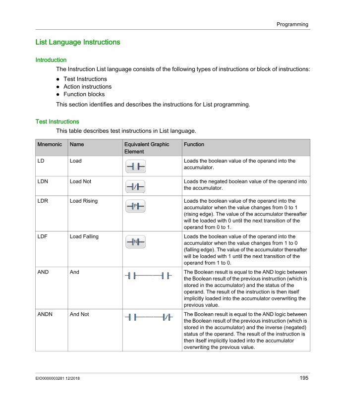
Programming
List Language Instructions
IntroductionThe Instruction List language consists of the following types of instructions or block of instructions: Test Instructions Action instructions Function blocksThis section identifies and describes the instructions for List programming.
Test InstructionsThis table describes test instructions in List language.
Mnemonic Name Equivalent Graphic Element
Function
LD Load Loads the boolean value of the operand into the accumulator.
LDN Load Not Loads the negated boolean value of the operand into the accumulator.
LDR Load Rising Loads the boolean value of the operand into the accumulator when the value changes from 0 to 1 (rising edge). The value of the accumulator thereafter will be loaded with 0 until the next transition of the operand from 0 to 1.
LDF Load Falling Loads the boolean value of the operand into the accumulator when the value changes from 1 to 0 (falling edge). The value of the accumulator thereafter will be loaded with 1 until the next transition of the operand from 1 to 0.
AND And The Boolean result is equal to the AND logic between the Boolean result of the previous instruction (which is stored in the accumulator) and the status of the operand. The result of the instruction is then itself implicitly loaded into the accumulator overwriting the previous value.
ANDN And Not The Boolean result is equal to the AND logic between the Boolean result of the previous instruction (which is stored in the accumulator) and the inverse (negated) status of the operand. The result of the instruction is then itself implicitly loaded into the accumulator overwriting the previous value.
EIO0000003281 12/2018 195
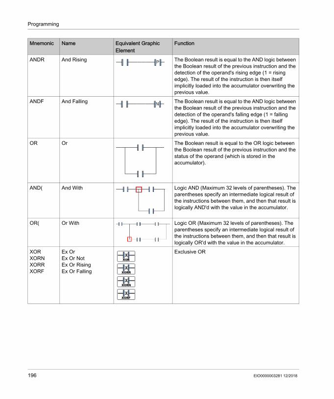
Programming
ANDR And Rising The Boolean result is equal to the AND logic between the Boolean result of the previous instruction and the detection of the operand's rising edge (1 = rising edge). The result of the instruction is then itself implicitly loaded into the accumulator overwriting the previous value.
ANDF And Falling The Boolean result is equal to the AND logic between the Boolean result of the previous instruction and the detection of the operand's falling edge (1 = falling edge). The result of the instruction is then itself implicitly loaded into the accumulator overwriting the previous value.
OR Or The Boolean result is equal to the OR logic between the Boolean result of the previous instruction and the status of the operand (which is stored in the accumulator).
AND( And With Logic AND (Maximum 32 levels of parentheses). The parentheses specify an intermediate logical result of the instructions between them, and then that result is logically AND'd with the value in the accumulator.
OR( Or With Logic OR (Maximum 32 levels of parentheses). The parentheses specify an intermediate logical result of the instructions between them, and then that result is logically OR'd with the value in the accumulator.
XORXORNXORRXORF
Ex OrEx Or NotEx Or RisingEx Or Falling
Exclusive OR
Mnemonic Name Equivalent Graphic Element
Function
196 EIO0000003281 12/2018
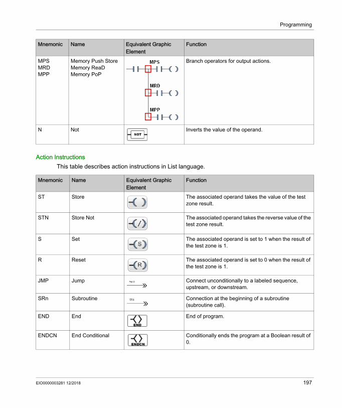
Programming
Action InstructionsThis table describes action instructions in List language.
MPSMRDMPP
Memory Push StoreMemory ReaDMemory PoP
Branch operators for output actions.
N Not Inverts the value of the operand.
Mnemonic Name Equivalent Graphic Element
Function
Mnemonic Name Equivalent Graphic Element
Function
ST Store The associated operand takes the value of the test zone result.
STN Store Not The associated operand takes the reverse value of the test zone result.
S Set The associated operand is set to 1 when the result of the test zone is 1.
R Reset The associated operand is set to 0 when the result of the test zone is 1.
JMP Jump Connect unconditionally to a labeled sequence, upstream, or downstream.
SRn Subroutine Connection at the beginning of a subroutine (subroutine call).
END End End of program.
ENDCN End Conditional Conditionally ends the program at a Boolean result of 0.
EIO0000003281 12/2018 197

Programming
Function BlocksThis table describes function blocks in List language.
Name Equivalent Graphic Element
Function
Timers, counters, registers, and so on.
For each of the function blocks, there are instructions for controlling the block. A structured form is used to connect the block inputs and outputs.Note: Outputs of function blocks cannot be connected to each other (vertical shorts).For more information, refer to Sotfware Objects (see EcoStruxure Machine Expert - Basic, Generic Functions Library Guide).
198 EIO0000003281 12/2018

Programming
Using Parentheses
IntroductionWith AND and OR logical operators, parentheses are used to nest logical instructions. In so doing, they specify divergences (branches) in the Ladder editor. Parentheses are associated with instructions as follows: Opening the parentheses is associated with the AND or OR operator. Closing the parentheses is an instruction (an operator with no operand) which is required for
each open parenthesis.
Example Using an AND InstructionThe following examples show how to use parentheses with an AND instruction:
NOTE: Refer to the reversibility procedure (see EcoStruxure Machine Expert - Basic, Generic Functions Library Guide) to obtain the equivalent Ladder Diagram.
Example Using an OR InstructionThe following example shows how to use parentheses with an OR instruction:
NOTE: Refer to the reversibility procedure (see EcoStruxure Machine Expert - Basic, Generic Functions Library Guide) to obtain the equivalent Ladder Diagram.
Rung Instruction0 LD %I0.0
AND %I0.1OR %I0.2ST %Q0.0
1 LD %I0.0AND( %I0.1OR %I0.2)ST %Q0.1
Rung Instruction0 LD %I0.0
AND %I0.1OR( %I0.2AND %I0.3)ST %Q0.0
EIO0000003281 12/2018 199

Programming
ModifiersThis table lists modifiers that can be assigned to parentheses.
NOTE: The '[' modifier can also be used in conjunction with other instructions serving as an operator. For more uses of the '[' in other instructions, refer to the Introduction to Numerical Operations.
Nesting ParenthesisIt is possible to nest up to 32 levels of parentheses. Observe the following rules when nesting parentheses: Each open parenthesis must have a corresponding closed parenthesis. Labels (%Li:), subroutines (SRi:), JMP instructions (JMP), and function block instructions must
not be placed in expressions between parentheses. Store instructions (ST, STN, S, and R) must not be programmed between parentheses. Stack instructions (MPS, MRD, and MPP) cannot be used between parentheses.
Modifier Function ExampleN Negation AND(N or OR(NF Falling edge AND(F or OR(FR Rising edge AND(R or OR(R[ Comparison See Comparison Instructions.
200 EIO0000003281 12/2018

Programming
Examples of Nesting ParenthesesThe following examples show how to nest parentheses:
NOTE: Refer to the reversibility procedure (see EcoStruxure Machine Expert - Basic, Generic Functions Library Guide) to obtain the equivalent Ladder Diagram.
Rung Instruction0 LD %I0.0
AND( %I0.1OR(N %I0.2AND %M3))ST %Q0.0
1 LD %I0.1AND( %I0.2OR( %I0.5AND %I0.6)AND %I0.4OR( %I0.7AND %I0.8))ST %Q0.0
EIO0000003281 12/2018 201

Programming
Grafcet (List) Programming
Section 5.14Grafcet (List) Programming
What Is in This Section?This section contains the following topics:
Topic PageDescription of Grafcet (List) Programming 203Grafcet (List) Program Structure 204How to Use Grafcet (List) Instructions in an EcoStruxure Machine Expert - Basic Program 208
202 EIO0000003281 12/2018

Programming
Description of Grafcet (List) Programming
IntroductionGrafcet (List) programming in EcoStruxure Machine Expert - Basic offer a simple method of translating a control sequence in to steps. You can translate control sequences in to Grafcet steps and then use these steps in a program using Grafcet instructions.The maximum number of Grafcet steps depend on the controller. The number of steps active at any one time is limited only by the total number of steps.
Grafcet InstructionsAn EcoStruxure Machine Expert - Basic Grafcet program has the following instructions:
Operator Operand IL Instruction Instruction Name Graphic Equivalent
Description
=*= x =*= x INITIAL STEP This instruction defines the intial step in the program.
=*= POST Not applicable
=*= POST POST PROCESSING(implicit operand)
This instruction defnes the post-processing and end sequential processing.
-*- x -*- x STEP This instruction defines a step in the program for transition validation.
# Not applicable
# DEACTIVATE CURRENT STEP (implicit operand)
This instruction deactivates the current step in the program.
# x # x DEACTIVATE CURRENT STEP and ACTIVATE STEP x
This instruction deactivates the current step and activates step x in the program.
#D x #D x DEACTIVATE CURRENT STEP and STEP x
This instruction deactivates the current step and step x in the program.
S x S x ACTIVATE STEP x This instruction activates step x in the program. The action has no affect on any other active steps.
R x R x DEACTIVATE STEP x This instruction deactivates step x in the program. The action has no affect on any other active steps.
x Grafcet step number (an integer starting from 1).
EIO0000003281 12/2018 203
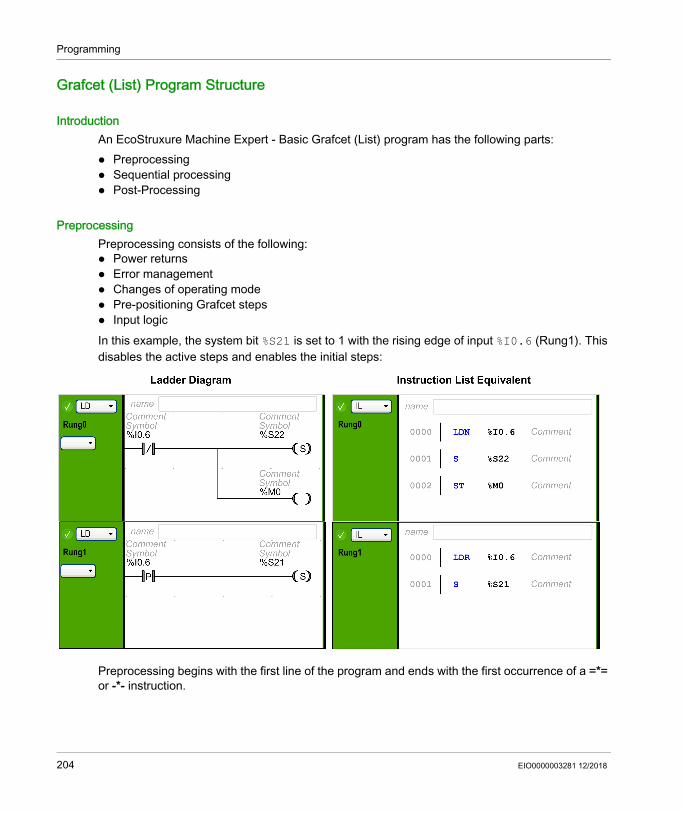
Programming
Grafcet (List) Program Structure
IntroductionAn EcoStruxure Machine Expert - Basic Grafcet (List) program has the following parts: Preprocessing Sequential processing Post-Processing
PreprocessingPreprocessing consists of the following: Power returns Error management Changes of operating mode Pre-positioning Grafcet steps Input logicIn this example, the system bit %S21 is set to 1 with the rising edge of input %I0.6 (Rung1). This disables the active steps and enables the initial steps:
Preprocessing begins with the first line of the program and ends with the first occurrence of a =*= or -*- instruction.
204 EIO0000003281 12/2018

Programming
System bits %S21, %S22, and %S23 are dedicated to Grafcet control. Each of these system bits is set to 1 (if needed) by the application, normally in preprocessing. The associated function is performed by the system at the end of preprocessing and the system bit is then reset to 0 by the system.
System Bit Name Description%S21 Grafcet initialization All active steps are deactivated and the initial steps are activated.%S22 Grafcet re-initialization All steps are deactivated.%S23 Grafcet pre-positioning This bit must be set to 1 if %Xi objects are explicitly written by the
application in preprocessing. If this bit is maintained to 1 by the preprocessing without any explicit change of the %Xi objects, Grafcet is frozen (no updates are taken into account).
EIO0000003281 12/2018 205

Programming
Sequential ProcessingSequential processing takes place in the chart (instructions representing the chart): Steps Actions associated with steps Transitions Transition conditionsExample:
Sequential processing ends with the execution of the POST instruction or with the end of the program.
206 EIO0000003281 12/2018
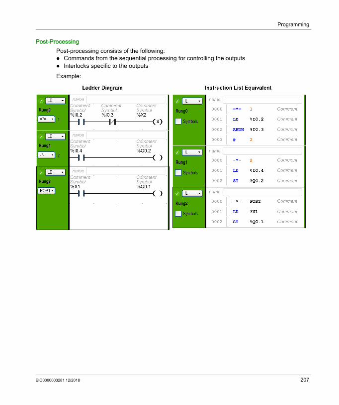
Programming
Post-ProcessingPost-processing consists of the following: Commands from the sequential processing for controlling the outputs Interlocks specific to the outputsExample:
EIO0000003281 12/2018 207
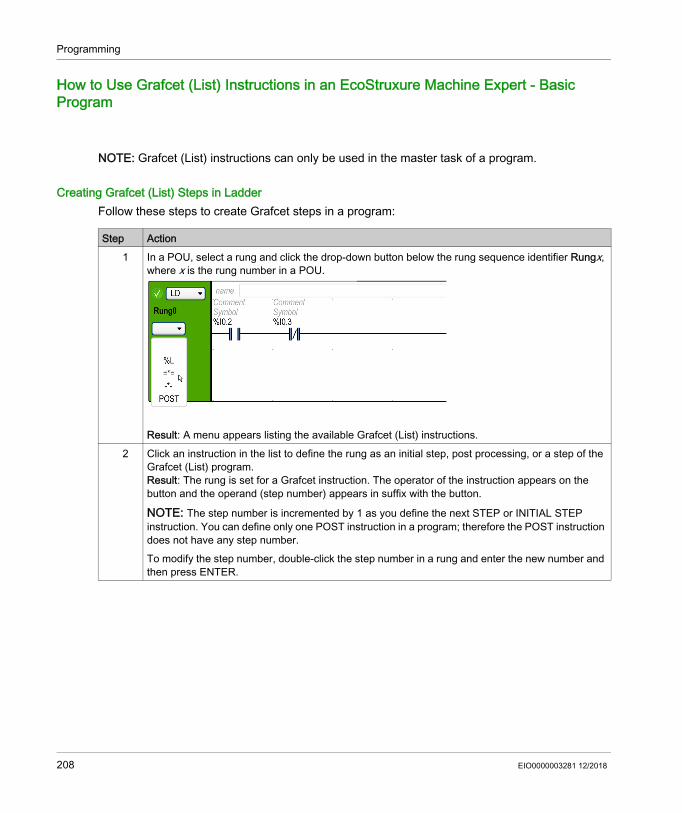
Programming
How to Use Grafcet (List) Instructions in an EcoStruxure Machine Expert - Basic Program
NOTE: Grafcet (List) instructions can only be used in the master task of a program.
Creating Grafcet (List) Steps in LadderFollow these steps to create Grafcet steps in a program:
Step Action1 In a POU, select a rung and click the drop-down button below the rung sequence identifier Rungx,
where x is the rung number in a POU.
Result: A menu appears listing the available Grafcet (List) instructions.2 Click an instruction in the list to define the rung as an initial step, post processing, or a step of the
Grafcet (List) program.Result: The rung is set for a Grafcet instruction. The operator of the instruction appears on the button and the operand (step number) appears in suffix with the button.
NOTE: The step number is incremented by 1 as you define the next STEP or INITIAL STEP instruction. You can define only one POST instruction in a program; therefore the POST instruction does not have any step number.To modify the step number, double-click the step number in a rung and enter the new number and then press ENTER.
208 EIO0000003281 12/2018

Programming
Activating or Deactivating Grafcet (List) Steps in LadderFollow these steps to activate or deactivate Grafcet (List) steps in a program:
Step Action1 In a POU, select a rung in your program.2
Click (to deactivate the current step and optionally activate a specified step) or (to deactivate the current step and to deactivate the specified step) and insert this element in the action zone of the rung (refer to Inserting a Graphic Element (see page 174)).
3 Alternatively, Press ALT+A to use ACTIVATE instruction or press ALT+D to use DEACTIVATE instruction in the rung.Result: The activate or deactivate ladder symbol appears in the action zone of the rung.Press ENTER to insert this element.
4 In the program rung, double-click Address field on the Grafcet activate or deactivate symbol and enter the Grafcet bit address (%Xi, where i is the step number).For example, %X4 refers to the step 4 of the Grafcet program. If %X4 is the address for the deactivate symbol, step 4 will be deactivated when the output of the rung, in which this symbol is used, is true.
NOTE: Current step is deactivated in every case.
EIO0000003281 12/2018 209
Programming
Grafcet (SFC) Programming
Section 5.15Grafcet (SFC) Programming
What Is in This Section?This section contains the following topics:
Topic PageIntroduction to Grafcet (SFC) Programming 211Using the Grafcet (SFC) Graphical Editor 214Branching 219Programming Best Practices 223
210 EIO0000003281 12/2018

Programming
Introduction to Grafcet (SFC) Programming
Introduction Grafcet (SFC) is a graphical programming language that describes a chronological order of execution of discrete tasks, known as steps. The order in which steps are executed is determined by transitions connecting the steps.
Elements of a Grafcet (SFC) POUA Grafcet (SFC) POU has the following components: Step: A step executes a set of actions defined in one of more rungs written in the Ladder/IL
programming languages. Steps can be: Initial step: Executed at the beginning of the program or following a controller restart. It is
represented by a cell with a double border. Regular step: Steps conditionally executed after the initial step completes execution.
Transition: A boolean expression evaluated between steps. It is the link between two or more steps. The boolean expression is defined in a single transition rung written in the Ladder/IL programming languages.
The following diagram is an example of a Grafcet (SFC) POU with an initial step, one regular step, and two transitions:
1 Initial step2 Transition from step 1 to step 23 Regular step4 Transition from step 2 back to step 1. An arrow is displayed on the link to indicate that the order of step
execution is not the default left to right, top to bottom.
Grafcet (SFC) POU RulesGrafcet POU can only be created in the master task of a program.Multiple Grafcet POUs can be created.
EIO0000003281 12/2018 211

Programming
Grafcet (SFC) ProcessingThe following rules are applied by the logic controller when executing the Grafcet (SFC): The master task cycle starts. The POUs that precede the first Grafcet (SFC) step are executed in a sequential way. The first Grafcet (SFC) step launches the Grafcet monitor. When the Grafcet monitor ends, the first POU that follows the last Grafcet (SFC) step is called.Grafcet monitor behavior: 1. The logic controller processes the associated Grafcet (SFC) system bits %S21, %S22, and
%S23.2. The logic controller updates the activation states of each Grafcet (SFC) step. Steps marked to be deactivated are deactivated. Steps marked to be activated are activated. Steps marked to be activated and deactivated at the same time will be or will remain
activated. Activation and deactivation lists are reset.
3. The logic controller scans the steps (loop from lowest defined step number to highest defined step number). When a scanned step is activated, the associated step code is called.
4. When a transition code activates or deactivates a step, this action is placed respectively in the activation or deactivation list for the next task cycle.
5. When the last active step code is executed, the Grafcet monitor ends.
Multi-Token BehaviorEcoStruxure Machine Expert - Basic Grafcet POU is multi-token which does not conform to IEC 61131-3.The initial situation is controlled by the steps defined as initial steps.Multiple steps can be active at the same time in a Grafcet POU.The active signal status processes take place along the directional links, triggered by switching one or more transitions. The direction of the process follows the directional links and runs from the underside of the predecessor step to the top side of the successive step.A transition is evaluated if the steps immediately preceding it are active. Transitions are not evaluated if the steps immediately preceding them are not active.A transition is triggered when the associated transition conditions are satisfied.Triggering a transition marks as deactivated the immediately preceding steps that are linked to the transition, and marks as activated the immediately following steps.The real activation or deactivation of the steps is performed at the beginning of each master task cycle (see Grafcet monitor (see page 212)).If more than one transition condition in a row of sequential steps has been satisfied, then one step is processed per cycle.If a step is activated and deactivated at the same time, then the step will be or will remain activated.More than one branch can be active with alternative branches.
212 EIO0000003281 12/2018
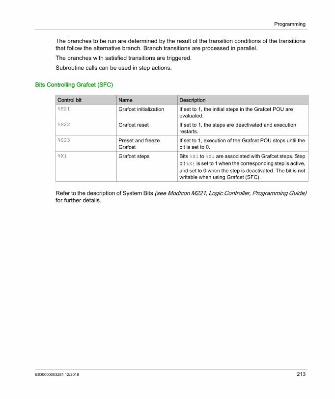
Programming
The branches to be run are determined by the result of the transition conditions of the transitions that follow the alternative branch. Branch transitions are processed in parallel.The branches with satisfied transitions are triggered.Subroutine calls can be used in step actions.
Bits Controlling Grafcet (SFC)
Refer to the description of System Bits (see Modicon M221, Logic Controller, Programming Guide) for further details.
Control bit Name Description%S21 Grafcet initialization If set to 1, the initial steps in the Grafcet POU are
evaluated.%S22 Grafcet reset If set to 1, the steps are deactivated and execution
restarts.%S23 Preset and freeze
GrafcetIf set to 1, execution of the Grafcet POU stops until the bit is set to 0.
%Xi Grafcet steps Bits %X1 to %Xi are associated with Grafcet steps. Step bit %Xi is set to 1 when the corresponding step is active, and set to 0 when the step is deactivated. The bit is not writable when using Grafcet (SFC).
EIO0000003281 12/2018 213
Programming
Using the Grafcet (SFC) Graphical Editor
OverviewThe Grafcet Graphical Editor is used for programming in Grafcet (SFC). To display the Grafcet Graphical Editor, select any n - Grafcet node in the tree view.The Grafcet Graphical Editor contains a grid of cells. Each cell contains one step, one transition, or both.The minimum size of a Grafcet POU is one step.The maximum number of Grafcet Step objects that the application can contain is: 96, if the Functional Level < 10.0 200, if the Functional Level >= 10.0
Detaching the Grafcet Graphical EditorYou can detach the Grafcet Graphical Editor window from the main EcoStruxure Machine Expert - Basic window so that it can be moved and resized independently. This allows you, for example, to move it to a separate monitor and display Grafcet POUs at the same time as IL/Ladder POUs.
To detach the window, click the button in the top right corner of the Grafcet Graphical Editor window.Drag the title bar of the window to move it. Close the window to revert to the normal view.
Inserting StepsDouble-click in any grid cell to add a step, or right-click in any grid cell and choose Add a step from the contextual menu that appears.You can see the Number of Grafcet steps used in the top right corner of the Grafcet Graphical Editor window.You can move a step by dragging and dropping in another grid cell.
Changing a Step Type (Initial or Regular)The first step created in the Grafcet Graphical Editor is by default an initial step.A Grafcet POU must contain at least one initial step. More than one step can be defined as initial steps.To change the step type (initial/regular), right-click the step and choose Set/Unset as initial step.
214 EIO0000003281 12/2018

Programming
Copying and Pasting a Step
Creating TransitionsLink steps together to define the order of execution of steps.To create a transition between two steps:
Editing LabelsTo edit the default labels of any step or transition.
Step Action1 Right-click on the step to copy and choose Copy from the contextual menu that appears.2 Right-click in an empty grid cell and choose Paste.
Result: A copy of the step appears. Copies of Ladder/IL rungs associated with the step are added below the corresponding Step subnode in the tree view.
Step Action1 Move the mouse over the bottom of a step.
Result: A green block appears2 Drag the mouse to the step you want to link to.3 Release the mouse button.
Result: A link and transition appear.
Step Action1 Double-click the label of any Grafcet (SFC) step or transition.2 Type the new name for the step or transition element and press ENTER.
For example, change the default Step_1 label to INIT.
EIO0000003281 12/2018 215

Programming
Programming Step FunctionalityThe functionality of a step is defined in one or more IL/Ladder language rungs.To define the functionality of a step:
Step Action1 Either:
Double-click a step in the Grafcet Graphical Editor. Select a Step node in the tree view, where n is the step number.
Result: The Grafcet Graphical Editor is closed. 2 Right-click on the selected Step node and choose Add rung from the contextual menu that
appears.Result: Rungs appear as subnodes of the Step node in the tree view window.
3 Program the rung in the Ladder or IL programming language and create additional rungs if needed, as described in Ladder Language Programming (see page 167) or Instruction List Programming (see page 190).
4 To display the Grafcet Graphical Editor again, either:
Click the icon. Select the n - Grafcet POU node, where n is the number of the Grafcet POU.
216 EIO0000003281 12/2018
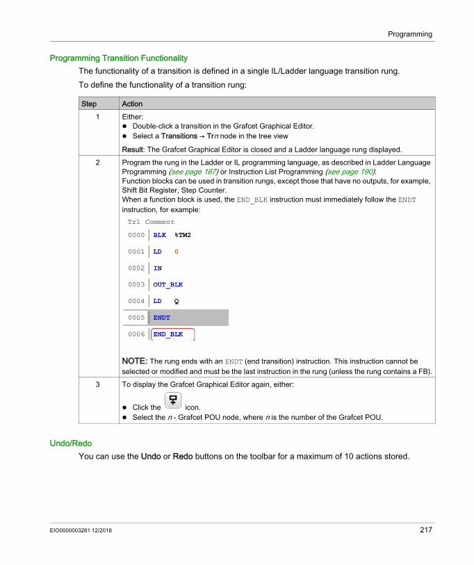
Programming
Programming Transition FunctionalityThe functionality of a transition is defined in a single IL/Ladder language transition rung.To define the functionality of a transition rung:
Undo/RedoYou can use the Undo or Redo buttons on the toolbar for a maximum of 10 actions stored.
Step Action1 Either:
Double-click a transition in the Grafcet Graphical Editor. Select a Transitions → Trn node in the tree view
Result: The Grafcet Graphical Editor is closed and a Ladder language rung displayed.2 Program the rung in the Ladder or IL programming language, as described in Ladder Language
Programming (see page 167) or Instruction List Programming (see page 190). Function blocks can be used in transition rungs, except those that have no outputs, for example, Shift Bit Register, Step Counter.When a function block is used, the END_BLK instruction must immediately follow the ENDT instruction, for example:
NOTE: The rung ends with an ENDT (end transition) instruction. This instruction cannot be selected or modified and must be the last instruction in the rung (unless the rung contains a FB).
3 To display the Grafcet Graphical Editor again, either:
Click the icon. Select the n - Grafcet POU node, where n is the number of the Grafcet POU.
EIO0000003281 12/2018 217

Programming
Deleting a Step or Transition
Step Action1 In the Grafcet Graphical Editor:
Select a step or transition and press the DELETE key. Right-click on the step or transition and choose Delete the selected items in the contextual
menu.Result: The selected step or transition is deleted.
NOTE: You cannot delete a step or transition from the tree view.
218 EIO0000003281 12/2018
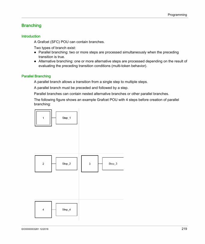
Programming
Branching
IntroductionA Grafcet (SFC) POU can contain branches. Two types of branch exist: Parallel branching: two or more steps are processed simultaneously when the preceding
transition is true. Alternative branching: one or more alternative steps are processed depending on the result of
evaluating the preceding transition conditions (multi-token behavior).
Parallel BranchingA parallel branch allows a transition from a single step to multiple steps.A parallel branch must be preceded and followed by a step.Parallel branches can contain nested alternative branches or other parallel branches.The following figure shows an example Grafcet POU with 4 steps before creation of parallel branching:
EIO0000003281 12/2018 219

Programming
To create a parallel branch for Steps 2 and 3:
The following figure shows a Grafcet POU after the creation of parallel branching:
Notice that the horizontal lines before and after the branched areas are double lines.
Alternative BranchingAn alternative branch must begin and end with a transition. Alternative branches can contain nested parallel branches or other alternative branches. With multi-token behavior, more than one parallel switch can be made from the transitions. The branches to be run are determined by the result of the transition conditions of the transitions that follow the alternative branch. The transitions of the branches are processed. The branches with satisfied transitions are triggered.
Step Action1 Create a transition between Step 1 and Step 2: move the mouse to the bottom of Step 1, then
drag to Step 2 and release the mouse button. A new link and transition appears.2 Draw a link between Step 3 and the transition: move the mouse to the top of Step 3, then drag
to the transition and release the mouse button. Result: A horizontal double line appears below the existing transition (see the figure that follows).
NOTE: To create a link between a transition and a step that is higher up in the POU, draw the link starting from the step and dragging to the transition.
3 To rejoin the branch with the main processing branch, create a transition between Step 2 and Step 4.
4 Draw a link between Step 3 and the new transition: move the mouse to the bottom of Step 3, then drag to the transition and release the mouse button.Result: A horizontal double line appears above the transition (see the figure that follows).
220 EIO0000003281 12/2018
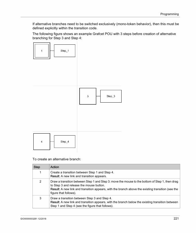
Programming
If alternative branches need to be switched exclusively (mono-token behavior), then this must be defined explicitly within the transition code.The following figure shows an example Grafcet POU with 3 steps before creation of alternative branching for Step 3 and Step 4:
To create an alternative branch:
Step Action1 Create a transition between Step 1 and Step 4.
Result: A new link and transition appears.2 Draw a transition between Step 1 and Step 3: move the mouse to the bottom of Step 1, then drag
to Step 3 and release the mouse button. Result: A new link and transition appears, with the branch above the existing transition (see the figure that follows).
3 Draw a transition between Step 3 and Step 4. Result: A new link and transition appears, with the branch below the existing transition between Step 1 and Step 4 (see the figure that follows).
EIO0000003281 12/2018 221

Programming
The following figure shows the Grafcet POU after creation of alternative branching:
Notice that the horizontal lines before and after the branched area are single lines.
222 EIO0000003281 12/2018

Programming
Programming Best Practices
Grafcet (SFC) Rules Steps must be connected by a transition:
You can add only one Grafcet POU in the same Grafcet Graphical Editor:
EIO0000003281 12/2018 223

Programming
Crossed LinksYou can have crossed links for the following reasons: Alternative (logical OR) branching (fork or junction) To save space on the cell grid. When lines cross there is no interaction between the lines and
it is used only for symbolic representation.
224 EIO0000003281 12/2018
Programming
Debugging in Online Mode
Section 5.16Debugging in Online Mode
What Is in This Section?This section contains the following topics:
Topic PageTrace Window 226Modifying Values 229Forcing Values 230Online Mode Modifications 231
EIO0000003281 12/2018 225

Programming
Trace Window
OverviewThe Trace window allows you to display in graphical form the values of specific analog and/or digital variables (limited to 12 hours of continuous recording). Each animation table can contain 1 trace at any one time. Up to 8 objects can be added to a trace. You can export the data to a file for further analysis.NOTE: The minimum configurable refresh period for the trace is 1 second (see page 139). Therefore, changes in values of boolean variables between master task cycles, for example, cannot be traced.
226 EIO0000003281 12/2018

Programming
Trace Window Presentation
Select Elapsed time to set tracing start time to 00:00:00, or Controller time to use the time and date of the logic controller as the start time of the trace.
EIO0000003281 12/2018 227

Programming
The Trace window displays separate graphs for each data type selected for tracing in the animation table: Integer and real values appear in the Numerical trace area.
All numerical values share the same scale on the graph.Select Auto scale for values to automatically adjust the vertical axis to display all values. Otherwise, type Maximum and Minimum values to display a fixed range of values. NOTE: You can type either integer or real values for Maximum and Minimum
Binary values appear in the Logical trace area.Each binary value is traced on an individual scale of 0 and 1.
Starting, Pausing, and Resetting the TraceClick Start to begin tracing the variables.Click Stop to pause real-time tracing.Click Reset to clear all previously traced data from graphs and reset the Recording duration value to 0.
Exporting the TraceClick Export to export all traced data to a file on the PC. The data is saved in comma-separated value (CSV) format.
228 EIO0000003281 12/2018

Programming
Modifying Values
IntroductionWhen in online mode, EcoStruxure Machine Expert - Basic allows you to modify the values of certain object types.Online updating is only possible if the object has read/write access. For example: The value of an analog input cannot be modified. The value of the Preset parameter (%TM0.P object) of a Timer function block can be updated.
Refer to the description of objects in the EcoStruxure Machine Expert - Basic Generic Functions Library Guide or the Programming Guide of your hardware platform for information on which object types have read/write access.To modify the value of an object, add it to an animation table (see page 141) and set its properties as required.
EIO0000003281 12/2018 229

Programming
Forcing Values
OverviewWhen in online mode, you can force the values of certain boolean object types to False (0) or True (1). This allows you to set addresses to specific values and prevent the program logic or an external system from changing the value. This function is used for the debugging and fine-tuning of programs.To force the values of boolean objects when in online mode, either: Use an animation table (see page 139) Modify boolean object values (see page 232) directly in the Ladder (LD) editorDigital inputs and outputs cannot be forced when: An input is used as a Run/Stop input Configured as fast counter (FC) inputs Configured as high speed counter (HSC) inputs Configured as reflex outputsNOTE: Forcing is performed at the end of the scan cycle. The image table of the outputs, however, may be modified due to the logic of your program, and may appear in animation tables and other data displays contrary to the forced state you selected. At the end of the scan, this will be corrected by acting upon the requested forced state and the physical output will indeed reflect that forced state.
230 EIO0000003281 12/2018

Programming
Online Mode Modifications
OverviewIt is possible to modify program while in online mode by: Adding rungs (see page 231) Modifying rungs (see page 231) Modifying Boolean Values in Ladder (see page 232) Modifying Function Block Parameters (see page 234) Modifying Constant Words (see page 235) Modifying Object Values in Operation and Comparison Blocks (see page 235) Deleting rungs (see page 236) Sending Modifications (see page 236)Any changes made must then be sent to the logic controller (see page 236).
Adding RungsYou can add new rungs (see page 90) to your program while in online mode.NOTE: The application must be configured with a functional level (see page 80) of at least Level 4.1 to be able to add new rungs in online mode. The following limitations apply until the new rung has been successfully sent to the logic controller: Rungs containing errors ( ) cannot be sent to the logic controller. Rungs must be written in Ladder language and cannot be converted to IL until they have been
successfully compiled. Rungs cannot contain Grafcet (List) steps. Labels cannot be added to the rung.
Modifying RungsYou can modify program rungs, in both the Instruction List (IL) and Ladder (LD) editors, while in online mode. However, the Grafcet (SFC) is not available online. Modified rungs appear with an orange background (see page 172).There are limits to the type of editing that you may perform and the instructions that you may edit, depending on whether the logic controller is in RUNNING or STOPPED state. These limits help protect the state of the controller and the integrity of the program.You can switch the display of a rung between Instruction List (IL) and Ladder (LD), even when in online mode.
EIO0000003281 12/2018 231

Programming
The following table indicates in which cases modifications are allowed:
NOTE: This table does not take into account the program structure modifications, which are not allowed in online mode.
Modifying Boolean Values in LadderFor rungs displayed in Ladder language, the values of certain boolean object types can be written to 1/0, forced to 1/0, or unforced.The following boolean object types can be modified:
Operations In STOPPED in IL In RUNNING in IL In STOPPED in Ladder
In RUNNING in Ladder
Event task content editable editable(1) editable editable(2)
Master / Periodic task content editable editable editable editableFree POU content editable editable(1) non-editable editable(2)
Rung with label editable editable(3) editable editable(4)
Rung with jump, or calling a subroutine or label
editable editable editable editable
Rung with any Grafcet instruction non-editable non-editable non-editable non-editableAdd/modify label non-editable non-editable non-editable non-editableMultiple operands (operation and comparison blocks)
editable editable editable editable
User-defined function rejected rejected editable editable(2)
User-defined function block rejected rejected editable editable(2)
(1) Except the first line of the first rung
(2) Except the first element of the first rung
(3) Except the first line of the rung
(4) Except the first element of the rung
Object type Write 1/0 Force to 1/0 or Unforce
Digital input (%Ix.y) N/A YesDigital output (%Qx.y) Yes Yes
System bit (%Si )1 Yes N/A
Memory bit (%Mi) Yes N/AMemory word bit (%MWi :Xj ) Yes N/A(1) If the system bit or system word can be written by the user program.
232 EIO0000003281 12/2018
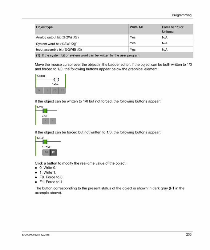
Programming
Move the mouse cursor over the object in the Ladder editor. If the object can be both written to 1/0 and forced to 1/0, the following buttons appear below the graphical element:
If the object can be written to 1/0 but not forced, the following buttons appear:
If the object can be forced but not written to 1/0, the following buttons appear:
Click a button to modify the real-time value of the object: 0. Write 0. 1. Write 1. F0. Force to 0. F1. Force to 1.The button corresponding to the present status of the object is shown in dark gray (F1 in the example above).
Analog output bit (%QWi :Xj ) Yes N/A
System word bit (%SWi :Xj)1 Yes N/A
Input assembly bit (%QWEi :Xj) Yes N/A
Object type Write 1/0 Force to 1/0 or Unforce
(1) If the system bit or system word can be written by the user program.
EIO0000003281 12/2018 233

Programming
To remove forcing, either: Click again on the F0/F1 button. Use an animation table (see page 139).NOTE: Forcing is performed at the end of the scan cycle. The image table of the outputs, however, may be modified due to the logic of your program, and may appear in animation tables and other data displays contrary to the forced state you selected. At the end of the scan, this will be corrected by acting upon the requested forced state and the physical output will indeed reflect that forced state.
Modifying Function Block Parameter ValuesTo modify a function block parameter in online mode:
Step Action1 In the Programming window, move the mouse cursor over the function block in the Ladder
editor.Result: The Configuration tooltip appears.The following illustration shows an example of the Configuration tooltip:
2 Click the value to modify.3 Type the value.4 To validate the modifications, you can use one of the following methods:
Click Apply. Click outside of the Configuration tooltip. Result: The Question window appears. Click OK.
234 EIO0000003281 12/2018

Programming
Modifying Constant WordsConfiguration values and runtime data values of constant word (%KW), constant double word (%KD), and constant floating point (%KF) objects can be modified while in online mode. In the properties grid, the columns Decimal, Binary, Hexadecimal and ASCII are editable:
To modify a constant word or floating point value in online mode:
Modifying Object Values in Operation and Comparison Blocks
Step Action1 In the Tools tab of the Programming window, choose Memory objects → Constant words.2 Click %KW, %KD, or %KF to select the type of constant to modify.3 Modify the value as required.
You can import the constant values. Refer to Importing the constant word properties (see page 148).
4 Click Apply. Result: The modified value is sent to the logic controller.
Step Action1 In the Programming window, move the mouse cursor over an operation or comparison block in
the Ladder editor.Result: The online modification tooltip appears:
2 Click the object or the symbol to modify.3 Enter the value.4 To validate, you can use one of the following methods:
Click . Press Enter.
If a value is incorrect, the value remains unchanged.
EIO0000003281 12/2018 235

Programming
Deleting RungsYou can delete rungs from your program while in online mode.NOTE: The application must be configured with a functional level (see page 80) of at least Level 4.1 to delete rungs in online mode. The following limitations apply: The rung must be displayed in Ladder language. The rung cannot be the only rung in a POU or Free POU. This limitation does not apply to
Grafcet POUs. The rung must not contain Grafcet (List) steps, be a subroutine rung, or contain any of the
following instructions: JMP END ENDC ENDCN G7
Only one rung at a time can be deleted.
Sending ModificationsIn IL, the modifications, when allowed, are automatically sent to the logic controller after validation of the edited IL line. If the modification is not allowed, a message appears.In Ladder, the modifications are not sent automatically. When in online mode, a button bar appears:
Click Send to send the modifications to the logic controller. This button is only active when the program has been modified in online mode and contains no errors.Click Rollback to discard the changes made in online mode and restore the original rung (that is, the version stored in the logic controller). The background color of the rung changes from orange to green. This button is only active when the program has been modified in online mode. Click Download non program data to download updates to non program data (project properties, symbols, comments, animation tables, and so on) to the logic controller. This button is only active when the non program data is not synchronized between the PC and the logic controller, for example, if an animation table has been modified prior to entering online mode. Click Backup to synchronize the contents of the flash memory and the RAM memory on the logic controller. This status is shown in the Controller Info window (see page 260). During the backup, the Ethernet communications in progress (for example, using Modbus TCP or the EXCH3 instruction) are temporarily suspended. NOTE: Be sure that online modifications have been saved to flash memory prior to creating a clone.
236 EIO0000003281 12/2018

Programming
Rungs that are modified are evaluated for their validity in the context of whether the controller is in RUNNING or STOPPED state. Modifications that would cause runtime errors, or change the structure of the program memory, are rejected in online mode.
EIO0000003281 12/2018 237

Programming
238 EIO0000003281 12/2018

EcoStruxure Machine Expert - BasicCommissioningEIO0000003281 12/2018
Commissioning
Chapter 6Commissioning
What Is in This Chapter?This chapter contains the following sections:
Section Topic Page6.1 Overview of the Commissioning Window 2406.2 Connect to a Logic Controller 2416.3 Controller Update 2536.4 Memory Management 2546.5 Controller Info 2606.6 RTC Management 262
EIO0000003281 12/2018 239
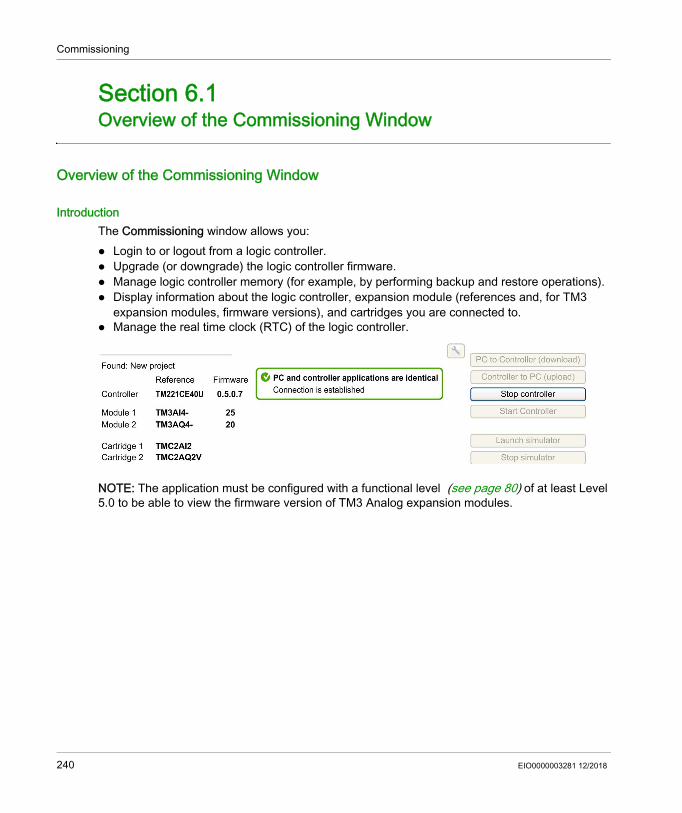
Commissioning
Overview of the Commissioning Window
Section 6.1Overview of the Commissioning Window
Overview of the Commissioning Window
IntroductionThe Commissioning window allows you: Login to or logout from a logic controller. Upgrade (or downgrade) the logic controller firmware. Manage logic controller memory (for example, by performing backup and restore operations). Display information about the logic controller, expansion module (references and, for TM3
expansion modules, firmware versions), and cartridges you are connected to. Manage the real time clock (RTC) of the logic controller.
NOTE: The application must be configured with a functional level (see page 80) of at least Level 5.0 to be able to view the firmware version of TM3 Analog expansion modules.
240 EIO0000003281 12/2018
Commissioning
Connect to a Logic Controller
Section 6.2Connect to a Logic Controller
What Is in This Section?This section contains the following topics:
Topic PageConnecting to a Logic Controller 242Downloading and Uploading Applications 249
EIO0000003281 12/2018 241

Commissioning
Connecting to a Logic Controller
OverviewClick Connect on the Commissioning window to manage the connection with the logic controller.
Connected ControllersTwo lists of logic controllers are displayed:1. Local Devices
Displays all logic controllers connected to the PC: With the physical COM ports of the PC (COM1, for example) With USB cables Through the virtualized COM ports (by USB-to-serial converters or Bluetooth dongles) With a modem connection that you choose to add manually. Use a modem connection
between EcoStruxure Machine Expert - Basic and a logic controller for monitoring purposes only.
NOTE: If a COM port is selected and the Keep Modbus driver parameters check box is ticked, the communication is established with the parameters defined in the Modbus driver.
2. Ethernet DevicesDisplays all logic controllers that are accessible by Ethernet (on the same subnet and not under a router or any device that blocks UDP broadcasts). This list includes logic controllers that are automatically detected by EcoStruxure Machine Expert - Basic as well as any controllers that you choose to add manually.
Manually Adding Ethernet ControllersTo manually add a logic controller to the Ethernet Devices list:
Step Action1 In the Remote lookup field, type the IP address of the logic controller to add, for example
12.123.134.212 Click Add to add the device to the Ethernet Devices list.
242 EIO0000003281 12/2018
Commissioning
Manually Adding Modem ConnectionsPrerequisites for availability of modem: If no modem is installed on the PC, the button is disabled. Verify in the Phone and Modem option of the Windows Control Panel that the modem is installed
and perform a test (in the Modem tab, click the modem to test and click Properties → Diagnostics → Query Modem). The response of the modem must be valid.
If the modem is an external modem connected on a COM port, verify that the communication settings are the same in: the modem advanced parameters, the communication port parameters, the Modbus driver parameters.
For more details on the installation and setting of SR2MOD03 modem, refer to the SR2MOD02 and SR2MOD03 Wireless Modem User Guide.
EIO0000003281 12/2018 243

Commissioning
To manually add a modem connection to the Local Devices list:
Step Action2
Click (Add modem configuration button) to open the Modem configuration window.Result: The Modem configuration window appears.
3 Select the COM port of the modem from the drop-down list:
4 Configure the communication parameters.For detailed information on the modem configuration parameters, refer to the table below.
5 Click Apply.
NOTE: This button is enabled only if all settings are correctly configured.
Result: The modem connection is added to the Local Devices list (for example COM2@0612345678,GenericModem).
244 EIO0000003281 12/2018

Commissioning
This table describes each parameter of the modem configuration:
Parameter Value Default value DescriptionPort COMx - Allows you to select the COM port of the
modem from the dropdown list. Device - - Displays the modem name.Phone Number - - Type the phone number of the remote modem
connected to the logic controller.This text field accepts all the characters and is limited to 32 characters in total. This field must contain at least one character to be able to apply the configuration.
AT init cmd - AT&D0 Allows you to edit the AT initialization command of the modem.The AT initialization command is not mandatory (if the field is empty the AT string is sent).
Escape chars - + Allows you to edit the escape character for the hang-up procedure.
Baud rate 1200240048009600192003840057600115200
19200 Allows you to select the data transmission rate (bits per second) of the modem.
Parity NoneEvenOdd
Even Allows you to select the parity of the transmitted data for error detection.
Data bits 78
8 Allows you to select the number of data bits.
Stop bits 12
1 Allows you to select the number of stop bits.
Timeout (ms) 0...60000 15000 Allows you to specify the transmission timeout (in ms).
Break timeout (ms) 0...10000 10 Allows you to specify the interframe timeout (in ms).If the check box Automatic is ticked, the value is automatically calculated.
EIO0000003281 12/2018 245

Commissioning
Connecting to a Logic ControllerTo log in to a logic controller:
Step Action1
Click (Refresh Devices button) to refresh the list of connected Ethernet devices.2 Select one of the logic controllers in the Local Devices or Ethernet Devices lists.
If a controller is connected by Ethernet on the same network cable than your PC, the IP address
of the controller appears in the list. Selecting the IP address in the list enables (IP Address Configuration button). Click this button to change the IP address of the controller.
NOTE: If you tick the check box Write to post configuration file, the Ethernet parameters are modified in the post configuration file and kept after a power cycle.
3
If required, click (Start Flashing LEDs button) to flash the LEDs of the selected controller to identify the controller physically by its flashing LEDs. Click this button again to stop flashing the LEDs.
NOTE: You can only use the Start Flashing LEDs button for logic controllers that are automatically added (with Auto discovery protocol enabled option selected).
4 Click Login to log in to the selected controller.Result: A status bar appears showing the connection progress.
5 When connected, the protection status of the application currently stored in the logic controller appears in the Selected Controller area of the window.When the connection is successfully established, details about the logic controller appear in the Selected Controller area of the window: The firmware revision The logic controller reference number The reference numbers of all expansion modules connected to the logic controller The current state of the connection between EcoStruxure Machine Expert - Basic and the
logic controller.6 EcoStruxure Machine Expert - Basic verifies whether the hardware configuration of the logic
controller is compatible with the configuration of the current project.If so, the application can be downloaded to the controller. The PC to Controller (download) button is enabled and you can proceed to download the application (see page 249).EcoStruxure Machine Expert - Basic verifies whether the non-program data (symbols, comments, animation tables, and so on) stored in the logic controller is the same as that of the current application. If not, an advisory message is displayed. EcoStruxure Machine Expert - Basic also verifies whether a more recent firmware version is available and, if so, displays a link you can click to begin the firmware upgrade.
246 EIO0000003281 12/2018
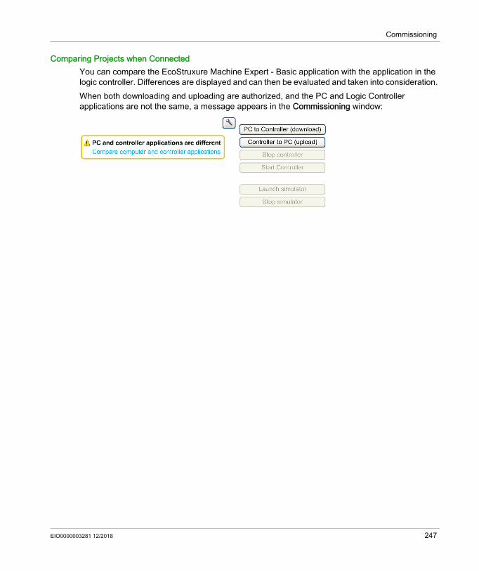
Commissioning
Comparing Projects when ConnectedYou can compare the EcoStruxure Machine Expert - Basic application with the application in the logic controller. Differences are displayed and can then be evaluated and taken into consideration. When both downloading and uploading are authorized, and the PC and Logic Controller applications are not the same, a message appears in the Commissioning window:
EIO0000003281 12/2018 247
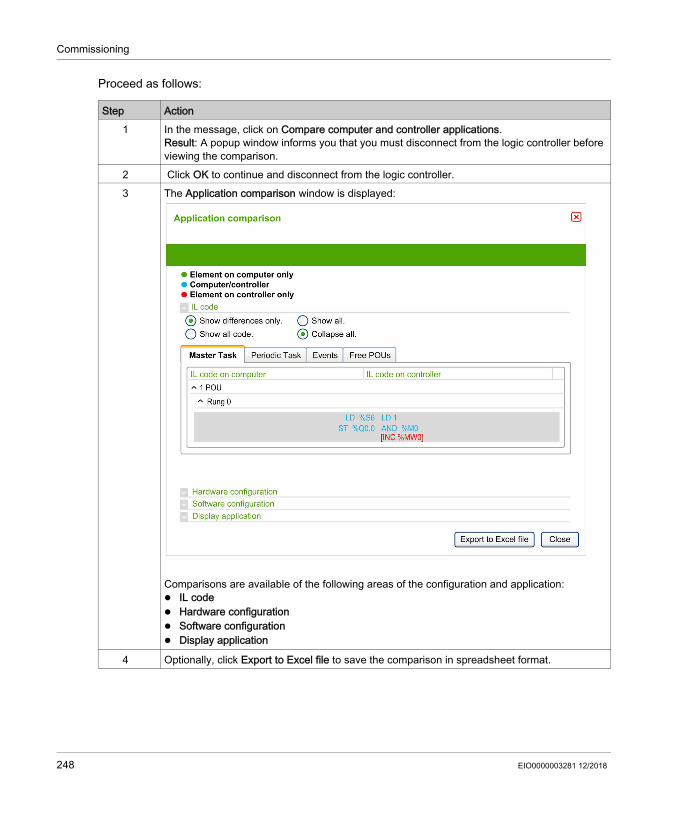
Commissioning
Proceed as follows:
Step Action1 In the message, click on Compare computer and controller applications.
Result: A popup window informs you that you must disconnect from the logic controller before viewing the comparison.
2 Click OK to continue and disconnect from the logic controller.3 The Application comparison window is displayed:
Comparisons are available of the following areas of the configuration and application: IL code Hardware configuration Software configuration Display application
4 Optionally, click Export to Excel file to save the comparison in spreadsheet format.
248 EIO0000003281 12/2018

Commissioning
Downloading and Uploading Applications
Downloading the ApplicationFollow these steps to download the application currently open in EcoStruxure Machine Expert - Basic to the logic controller:
Step Action1 Click Connect in the commissioning tree of the Commissioning window.2 Select one of the logic controllers in the Local Devices or Ethernet Devices lists.3 Click Login to log in to the selected controller.4
Optionally, click Download Settings.If you do not want memory words (%MW) and memory bits (%M) to be reset after the download, clear the Reset memories option.
NOTE: The option in Memories is only available for logic controllers with firmware version greater than or equal to 1.3.3.y.The options in Program Properties and Project Properties are only available for logic controllers with firmware version greater than or equal to 1.4.1.y.
5 If the PC to Controller (download) button is not available, verify that: The application stored in the logic controller is identical to the EcoStruxure Machine
Expert - Basic application. The hardware configuration of the logic controller system is compatible with the
configuration in the EcoStruxure Machine Expert - Basic application. The logic controller is not password-protected. If it is, enter the password.
Click PC to Controller (download).6 If the non-program data of the current application is not identical to that stored in the
controller, the non-program data only is downloaded to the controller. 7 If the application has been configured to Start in Run, a hazard message is displayed and
prompts you to confirm that the application has been so configured.Click OK to confirm the download of the application or click Cancel and modify the configuration.
8 Click OK to continue the transfer and overwrite the logic controller application.Result: A status bar appears indicating the connection status.
9 To run the application you have downloaded, click Run controller and click OK to confirm the action.If a message appears informing you that the operating mode cannot be changed, click Close and verify the RUN/STOP switch on the logic controller, and/or, the RUN/STOP input as they may prevent the controller from passing into RUNNING. Otherwise, refer to the Hardware Guide of your logic controller for details.
EIO0000003281 12/2018 249
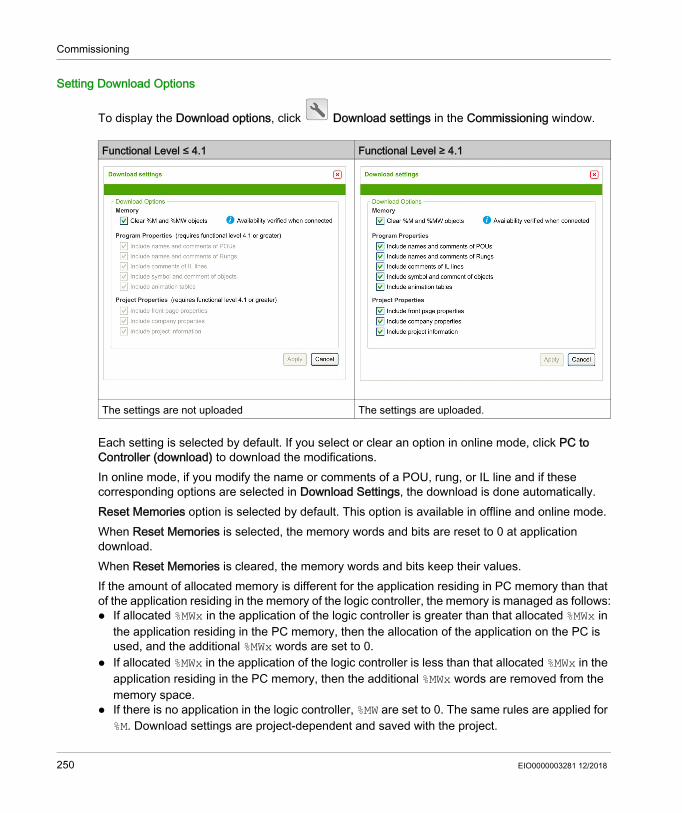
Commissioning
Setting Download Options
To display the Download options, click Download settings in the Commissioning window.
Each setting is selected by default. If you select or clear an option in online mode, click PC to Controller (download) to download the modifications.In online mode, if you modify the name or comments of a POU, rung, or IL line and if these corresponding options are selected in Download Settings, the download is done automatically.Reset Memories option is selected by default. This option is available in offline and online mode.When Reset Memories is selected, the memory words and bits are reset to 0 at application download.When Reset Memories is cleared, the memory words and bits keep their values. If the amount of allocated memory is different for the application residing in PC memory than that of the application residing in the memory of the logic controller, the memory is managed as follows: If allocated %MWx in the application of the logic controller is greater than that allocated %MWx in
the application residing in the PC memory, then the allocation of the application on the PC is used, and the additional %MWx words are set to 0.
If allocated %MWx in the application of the logic controller is less than that allocated %MWx in the application residing in the PC memory, then the additional %MWx words are removed from the memory space.
If there is no application in the logic controller, %MW are set to 0. The same rules are applied for %M. Download settings are project-dependent and saved with the project.
Functional Level ≤ 4.1 Functional Level ≥ 4.1
The settings are not uploaded The settings are uploaded.
250 EIO0000003281 12/2018

Commissioning
Uploading an ApplicationFollow these steps to upload the application stored in the logic controller to EcoStruxure Machine Expert - Basic:
NOTE: The value of the Reset Memories option is not saved when you upload an application.
Downloading or Uploading a Password-Protected ApplicationIf you download or upload an application that was password-protected in a lesser version of EcoStruxure Machine Expert - Basic, the actions you can or must do depend on the versions:
Step Action1 Click Connect in the commissioning tree of the Commissioning window.2 Select one of the logic controllers in the Local Devices or Ethernet Devices lists.3 Click Login to log in to the selected controller.
If the logic controller is password protected, type the password and click OK to connect.4 Click Controller to PC (upload).
If the Controller to PC (upload) button is not available, confirm whether the application stored in the logic controller is identical to the EcoStruxure Machine Expert - Basic application.
5 Click OK to confirm upload from the logic controller.Result: A status bar appears indicating the connection status. When the transfer completes, the application is uploaded from the logic controller into EcoStruxure Machine Expert - Basic.
Operation EcoStruxure Machine Expert - Basic version
Functional level of the Application
Firmware version
Actions
Downloading≤1.5 ≤5.0 ≤1.5 Downloading process does not use the
latest security strategy.≥ 1.5.1 Downloading process possible and
password visible.≥ 5.1 – You cannot download.
≥ 1.5 SP1 ≤5.0 ≤ 1.5 If the application is password-protected, you cannot download.
≥ 1.5.1 You must do one of the following actions: Upgrade the functional level to 5.1. Let the password blank. Disable the application protection.
≥ 5.1 ≤ 1.5 You cannot download.≥ 1.5.1 Downloading process uses the latest
security strategy.
EIO0000003281 12/2018 251

Commissioning
Uploading≤1.5 ≤5.0 ≤1.5 Uploading process does not use the latest
security strategy.≥ 1.5.1 You must do one of the following actions:
Downgrade the firmware version. Upgrade the EcoStruxure Machine
Expert - Basic version.≥ 5.1 – You cannot upload.
≥ 1.5 SP1 ≤5.0 ≤1.5 Uploading process does not use the latest security strategy.
≥ 1.5.1 Uploading process uses the latest security strategy.
≥ 5.1 ≤1.5 You cannot upload.≥ 1.5.1 Uploading process uses the latest security
strategy.
Operation EcoStruxure Machine Expert - Basic version
Functional level of the Application
Firmware version
Actions
252 EIO0000003281 12/2018

Commissioning
Controller Update
Section 6.3Controller Update
Controller Firmware Updates
OverviewYou can download firmware updates to the logic controller either directly from EcoStruxure Machine Expert - Basic or using an SD card.
Downloading a Firmware Update to the Logic ControllerPerforming a firmware update preserves the application program present in the controller, including the Boot Application in the non-volatile memory.Follow these steps to download firmware updates to the logic controller:
If you remove power to the device, or there is a power outage or communication interruption during the transfer of the application, your device may become inoperative. If a communication interruption or a power outage occurs, reattempt the transfer. If there is a power outage or communication interruption during a firmware update, or if an invalid firmware is used, your device will become inoperative. In this case, use a valid firmware and reattempt the firmware update.
Step Action1 Verify that you are not connected to the logic controller when using Firmware Update.2 Click Commissioning → Controller Update.3 Click Update.
The first page of the executive loader (OS loader) wizard appears.
NOTICEINOPERABLE EQUIPMENT Do not interrupt the transfer of the application program or a firmware change once the transfer
has begun. Re-initiate the transfer if the transfer is interrupted for any reason. Do not attempt to place the device (logic controller, motion controller, HMI controller or drive)
into service until the file transfer has completed successfully.Failure to follow these instructions can result in equipment damage.
EIO0000003281 12/2018 253

Commissioning
Memory Management
Section 6.4Memory Management
Managing Logic Controller Memory
OverviewIn EcoStruxure Machine Expert - Basic, you can back up, restore, or erase the different elements from or to the logic controller to which you are connected.Backup, restore, and erase options are available only in online mode.
Backing Up to a PC or Controller SD CardFollow these steps to back up the logic controller memory to a PC or to the controller SD card:
WARNINGUNINTENDED EQUIPMENT OPERATION Verify that the controller you are connected to is the intended target before performing the
erase or the restore operation. Verify the state of security of your machine or process environment before performing the
erase or the restore operation from a remote location.Failure to follow these instructions can result in death, serious injury, or equipment damage.
Step Action1 Log in to the logic controller.2 Select Memory Management in the left-hand area of the Commissioning window.3 In the Action list, choose Backup from Controller.4 To back up to a PC: Under Destination, choose PC. Click the browse button, navigate to the
folder in which to write the backup file.orTo back up to an SD card: Under Destination, choose Controller SD Card folder. Insert an SD card into the SD card slot of the logic controller.
NOTE: The SD card must not be empty or contain a script.cmd file to avoid creating a clone or the script execution (see Modicon M221, Logic Controller, Programming Guide).
254 EIO0000003281 12/2018

Commissioning
NOTE: If you choose to back up memory values, you can initiate a backup while the logic controller is in RUNNING state. As a consequence, the backup would not necessarily be coherent because the memory variables value can be modified from one scan to another. If you wish to have a consistent set of values for the variables, you may need to first put the logic controller into STOPPED state.
RestoringFollow these steps to restore logic controller elements from a PC:
5 Select the elements to back up by selecting the options: Backup firmware Backup program Backup memory values Backup log file Backup post configuration file
When Backup memory values is selected in a PC backup, specify the First Memory Bit, Last Memory Bit, First Memory Word, and Last Memory Word to be included in the backup.
6 Click Backup from Controller to begin the backup operation.The elements are saved to the specified PC folder or SD card as an SD card image (.smbk).A report window appears displaying a list of information or detected error messages about the backup operation.
Step Action
Step Action1 Log in to the logic controller.2 Select Memory Management in the left-hand area of the Commissioning window.3 In the Action list, choose Restore to Controller.4 Choose the source folder that contains the backup files on the PC.5 Select the elements you want to restore to the logic controller.6 Click Restore to Controller to begin the restore operation.
A report window appears displaying a list of information or detected error messages about the restore operation.
EIO0000003281 12/2018 255
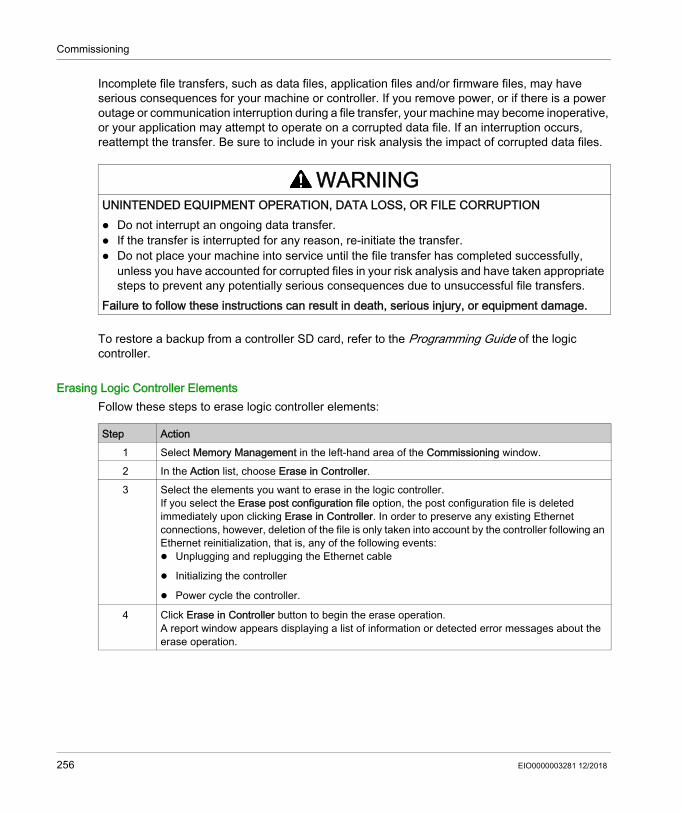
Commissioning
Incomplete file transfers, such as data files, application files and/or firmware files, may have serious consequences for your machine or controller. If you remove power, or if there is a power outage or communication interruption during a file transfer, your machine may become inoperative, or your application may attempt to operate on a corrupted data file. If an interruption occurs, reattempt the transfer. Be sure to include in your risk analysis the impact of corrupted data files.
To restore a backup from a controller SD card, refer to the Programming Guide of the logic controller.
Erasing Logic Controller ElementsFollow these steps to erase logic controller elements:
WARNINGUNINTENDED EQUIPMENT OPERATION, DATA LOSS, OR FILE CORRUPTION Do not interrupt an ongoing data transfer. If the transfer is interrupted for any reason, re-initiate the transfer. Do not place your machine into service until the file transfer has completed successfully,
unless you have accounted for corrupted files in your risk analysis and have taken appropriate steps to prevent any potentially serious consequences due to unsuccessful file transfers.
Failure to follow these instructions can result in death, serious injury, or equipment damage.
Step Action1 Select Memory Management in the left-hand area of the Commissioning window.2 In the Action list, choose Erase in Controller.3 Select the elements you want to erase in the logic controller.
If you select the Erase post configuration file option, the post configuration file is deleted immediately upon clicking Erase in Controller. In order to preserve any existing Ethernet connections, however, deletion of the file is only taken into account by the controller following an Ethernet reinitialization, that is, any of the following events: Unplugging and replugging the Ethernet cable
Initializing the controller
Power cycle the controller.
4 Click Erase in Controller button to begin the erase operation. A report window appears displaying a list of information or detected error messages about the erase operation.
256 EIO0000003281 12/2018
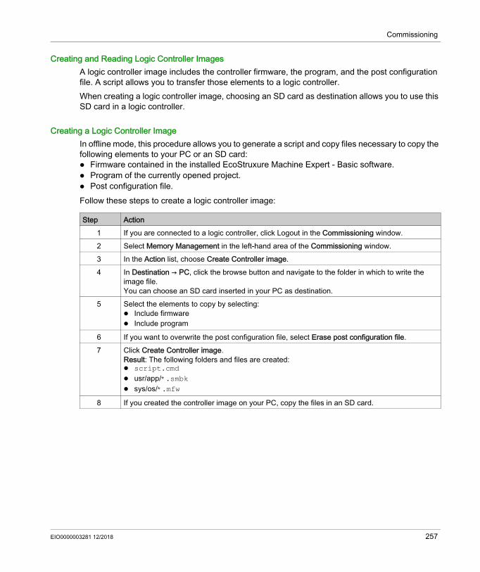
Commissioning
Creating and Reading Logic Controller ImagesA logic controller image includes the controller firmware, the program, and the post configuration file. A script allows you to transfer those elements to a logic controller.When creating a logic controller image, choosing an SD card as destination allows you to use this SD card in a logic controller.
Creating a Logic Controller ImageIn offline mode, this procedure allows you to generate a script and copy files necessary to copy the following elements to your PC or an SD card: Firmware contained in the installed EcoStruxure Machine Expert - Basic software. Program of the currently opened project. Post configuration file.Follow these steps to create a logic controller image:
Step Action1 If you are connected to a logic controller, click Logout in the Commissioning window.2 Select Memory Management in the left-hand area of the Commissioning window.3 In the Action list, choose Create Controller image.4 In Destination → PC, click the browse button and navigate to the folder in which to write the
image file.You can choose an SD card inserted in your PC as destination.
5 Select the elements to copy by selecting: Include firmware Include program
6 If you want to overwrite the post configuration file, select Erase post configuration file.7 Click Create Controller image.
Result: The following folders and files are created: script.cmd usr/app/*.smbk sys/os/*.mfw
8 If you created the controller image on your PC, copy the files in an SD card.
EIO0000003281 12/2018 257

Commissioning
The following illustration presents an example of the settings:
Reading a Logic Controller ImageIn offline mode, this procedure allows you to open a .smbk image file in EcoStruxure Machine Expert - Basic as a project.NOTE: The image opened must have been previously created either through Create Controller image operation or by a backup from the controller (see page 257).Follow these steps to read a logic controller image:
Step Action1 If you are connected to a logic controller, click Logout in the Commissioning window.2 Select Memory Management in the left-hand area of the Commissioning window.3 In the Action list, choose Read image.4 In Source → PC, click the browse button and navigate to the folder containing the image file
(.smbk).Read program is selected by default. To read a image file, you have to select it.
5 Click Read image to read the program and open a project.
258 EIO0000003281 12/2018

Commissioning
The following illustration presents an example of the settings:
EIO0000003281 12/2018 259
Commissioning
Controller Info
Section 6.5Controller Info
Controller Information
OverviewClick Controller info in the left-hand area of the Commissioning window to display the following information on the present state of the logic controller: Executable RAM: This option verifies if a valid application is stored in the RAM memory of the
logic controller. This information can also be obtained from within a program by testing bit 14 of the system word %SW7 (see Modicon M221, Logic Controller, Programming Guide).
Protected RAM: This option is checked if the application in the RAM memory of the logic controller is password-protected. This information can also be obtained from within a program by testing bit 8 of the system word %SW7 (see Modicon M221, Logic Controller, Programming Guide).
Forced I/O: This option is checked if 1 or more digital inputs or outputs on the logic controller are being forced to a specific value (see page 141). In this case, system bit %S14 (see Modicon M221, Logic Controller, Programming Guide) (IO force activated) is set to 1.
RAM synchronized with Flash: This option is checked, if the application stored in non-volatile memory is not identical to the application in RAM memory.The option is unchecked if either: online modifications to the application have not yet been sent to the logic controller (by
clicking the Backup button on the Programming tab). the logic controller has not been initialized since the modifications were made (by clicking the
Initialize controller button on the toolbar). Status: The present state of the logic controller.
This information can also be obtained from within a program by testing the system word %SW6. For more information on controller states, see the programming guide of your logic controller.
Last stopped on: The date and time that the logic controller was last stopped (STOPPED, HALTED, and so on).This information can also be obtained from within a program by testing the system word %SW54 through %SW57.
Last stopped reason: Displays the reason for the most recent stop of the logic controller.This information can also be obtained from within a program by testing the system word %SW58.
260 EIO0000003281 12/2018

Commissioning
Scan time (µs): The following scan times: Minimum (in microseconds): Shortest scan time since the last power-on of the logic
controller.This information can also be obtained from within a program by testing the system word %SW32 (in milliseconds).
Current (in microseconds): The scan time. This information can also be obtained from within a program by testing the system word %SW30 (in milliseconds).
Maximum (in microseconds): The longest scan time since the last power-on of the logic controller.This information can also be obtained from within a program by testing the system word %SW31 (in milliseconds).
Controller time: The following information is displayed only if the logic controller has a real time clock (RTC): Date (DD/MM/YYYY): The present date stored in the logic controller.
This information can also be obtained from within a program by testing the system words %SW56 and %SW57.
Time (HH:MM:SS): The present time stored in the logic controller. This information can also be obtained from within a program by testing the system words %SW54 and %SW55.
The date and time are presented in same format as specified for the PC. Ethernet information: The following information is displayed only if the logic controller has an
embedded Ethernet connection: IP address: The IP address of the logic controller.
This information can also be obtained from within a program by testing the system words (see Modicon M221, Logic Controller, Programming Guide) %SW33 and %SW34.
Subnet mask: The subnet mask of the logic controller. This information can also be obtained from within a program by testing the system words %SW35 and %SW36.
Gateway address: The gateway address of the logic controller. This information can also be obtained from within a program by testing the system words %SW37 and %SW38.
SL1 Post Configuration status: The parameters with the activated check box are defined by the post configuration file. This information can also be obtained from within a program by testing the system word %SW98 (see Modicon M221, Logic Controller, Programming Guide).
SL2 Post Configuration status: The parameters with the activated check box are defined by the post configuration file. This information can also be obtained from within a program by testing the system word %SW99 (see Modicon M221, Logic Controller, Programming Guide).
ETH Post Configuration status: The parameters with the activated check box are defined by the post configuration file. This information can also be obtained from within a program by testing the system word %SW100 (see Modicon M221, Logic Controller, Programming Guide).
EIO0000003281 12/2018 261
Commissioning
RTC Management
Section 6.6RTC Management
Managing the RTC
OverviewThe RTC Management window enables you to set the real time clock (RTC) of the logic controller. This is only possible if EcoStruxure Machine Expert - Basic is connected to a logic controller that supports an RTC.
Updating the RTC
Step Action1 Select the RTC Management option in the left-hand area of the Commissioning window.2 If in online mode, the Current controller time is displayed.
Choose the mode for setting the logic controller time: Manual : This mode displays the date and time and lets you manually choose what date and
time to set in the logic controller. Automatic : This mode sets the time in the logic controller to the current time of the PC on
which EcoStruxure Machine Expert - Basic is installed.3 Click Apply.
262 EIO0000003281 12/2018

EcoStruxure Machine Expert - BasicSimulatorEIO0000003281 12/2018
Simulator
Chapter 7Simulator
What Is in This Chapter?This chapter contains the following topics:
Topic PageOverview of the EcoStruxure Machine Expert - Basic Simulator 264EcoStruxure Machine Expert - Basic Simulator I/O Manager Window 266EcoStruxure Machine Expert - Basic Simulator Time Management Window 268Modifying Values Using EcoStruxure Machine Expert - Basic Simulator 271How to Use the EcoStruxure Machine Expert - Basic Simulator 275Launching Simulation in Vijeo-Designer 276
EIO0000003281 12/2018 263

Simulator
Overview of the EcoStruxure Machine Expert - Basic Simulator
IntroductionEcoStruxure Machine Expert - Basic simulator allows you to: Simulate a connection between the PC, the logic controller, and any expansion modules. Run and test a program without a logic controller and expansion modules, connected to the PC
physically.The simulator replicates the behavior of the logic controller and is a virtual logic controller that you connect to with EcoStruxure Machine Expert - Basic.NOTE: Security parameters (see Modicon M221, Logic Controller, Programming Guide) are not applied when using the simulator. Once you launch the simulator, you can connect, run, stop and other associated actions that you would accomplish while connected to a physical logic controller.NOTE: The simulator supports up to 2 connections; one for EcoStruxure Machine Expert - Basic and other one for data purpose (for example, HMI communication).
Accessing the EcoStruxure Machine Expert - Basic Simulator
EcoStruxure Machine Expert - Basic Simulator WindowsEcoStruxure Machine Expert - Basic simulator has the following 2 windows: Simulator time management window
Lets you control the RTC of the controller in order to simulate the passage of time and its effect on the logical constructs affected by the RTC.
Simulator I/O manager windowLets you manage the state of inputs/outputs of the controller and the expansion modules.
Step Action1 Ensure that the program is valid. Otherwise, the simulator launch is interrupted with a compilation
error detected message that appears on the screen.2 Launch the simulator by any of the following methods:
Click Launch simulator in the commissioning task area. Press CTRL+B in the Commissioning window.
Click (launch simulator button) in the EcoStruxure Machine Expert - Basic tool bar.
264 EIO0000003281 12/2018

Simulator
After the connection between the PC and the virtual logic controller has been successfully established (refer to How to Use the EcoStruxure Machine Expert - Basic Simulator (see page 275)), EcoStruxure Machine Expert - Basic Simulator I/O manager window appears on the screen:
1 Simulator I/O manager window (see page 266)
EIO0000003281 12/2018 265

Simulator
EcoStruxure Machine Expert - Basic Simulator I/O Manager Window
OverviewSimulator I/O manager window has the following components: LED status:
To monitor the LED status of a simulated controller. Input/output status:
To control the inputs and outputs when the program is running.
Simulator I/O Manager WindowThis graphic shows the simulator I/O manager window:
Click the pin symbol on the left-top of this window to pin or unpin the window to the foreground.Click the minimize symbol on the right-top of this window to minimize the window in taskbar.
LED StatusThe PWR, RUN, ERR, and STAT LEDs are simulated in the EcoStruxure Machine Expert - Basic simulator I/O manager window as they would appear on a connected base controller.The following are the LED states displayed in the simulator I/O manager window of a simulated logic controller:
LED Status InformationPWR Indicates whether the simulated logic controller is powered up or not.RUN Indicates the RUN state of the simulated logic controller.ERR Indicates the ERR state of the simulated logic controller.STAT The operation of the STAT LED is defined by the user logic.
266 EIO0000003281 12/2018

Simulator
Input/Output StatusSimulator I/O manager window lets you monitor and control the I/Os of a controller and expansion module when a program is running.The inputs and outputs are displayed in a list of numbers. This list depends on the I/Os of the selected controller and expansion module. For example, if your controller has n digital inputs, the number list will display number starting from 0...(n-1), where each number corresponds to the digital input at the corresponding input channel.For a controller, the I/Os displayed are: IN: Digital inputs. OUT: Digital outputs. ANA: Analog inputs.For an expansion module, the I/Os displayed are: IN: Digital/analog inputs. OUT: Digital/analog outputs.NOTE: The analog I/Os are displayed with their current values on right-hand side of the analog input number.Digital I/O status is identified by the text color of the I/O numbers: Green: I/O is set to 1. Black: I/O is set to 0.Analog I/O status is identified by the value: - (hyphen): I/O is not configured. Number: Current value of the I/O.
EIO0000003281 12/2018 267

Simulator
EcoStruxure Machine Expert - Basic Simulator Time Management Window
OverviewSimulator Time Management window has the following components: Date / Time simulation range for the execution of the program in the simulator: Beginning Date and Time End Date and Time Stop at the End check box (stop the execution of the program when the End Date and Time
are reached) Time control scroll bar: To move the simulation of the passage of time manually forward or back
Date and Time display: Date and Time of the simulated RTC of the simulator
Control buttons: To reset, jump back, jump forward, or end the time management associated with the RTC
Increment bar: To fix the rate of the simulated passage of time relative to real time
Simulator Time Management WindowTo display the Time Management window:
This graphic presents the simulator Time Management window:
Step Action1 Right-click on the top bar of the Simulator I/O Management window.2 Choose Time Management.
268 EIO0000003281 12/2018
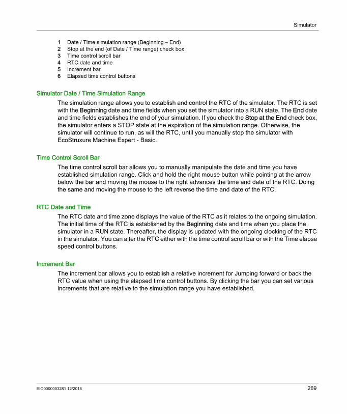
Simulator
1 Date / Time simulation range (Beginning – End)2 Stop at the end (of Date / Time range) check box3 Time control scroll bar4 RTC date and time5 Increment bar6 Elapsed time control buttons
Simulator Date / Time Simulation RangeThe simulation range allows you to establish and control the RTC of the simulator. The RTC is set with the Beginning date and time fields when you set the simulator into a RUN state. The End date and time fields establishes the end of your simulation. If you check the Stop at the End check box, the simulator enters a STOP state at the expiration of the simulation range. Otherwise, the simulator will continue to run, as will the RTC, until you manually stop the simulator with EcoStruxure Machine Expert - Basic.
Time Control Scroll BarThe time control scroll bar allows you to manually manipulate the date and time you have established simulation range. Click and hold the right mouse button while pointing at the arrow below the bar and moving the mouse to the right advances the time and date of the RTC. Doing the same and moving the mouse to the left reverse the time and date of the RTC.
RTC Date and TimeThe RTC date and time zone displays the value of the RTC as it relates to the ongoing simulation. The initial time of the RTC is established by the Beginning date and time when you place the simulator in a RUN state. Thereafter, the display is updated with the ongoing clocking of the RTC in the simulator. You can alter the RTC either with the time control scroll bar or with the Time elapse speed control buttons.
Increment BarThe increment bar allows you to establish a relative increment for Jumping forward or back the RTC value when using the elapsed time control buttons. By clicking the bar you can set various increments that are relative to the simulation range you have established.
EIO0000003281 12/2018 269

Simulator
Elapsed Time Control ButtonsYou can use the control buttons to effect the RTC value, and therefore manipulate its affect on your program running in the simulator as follows:
Graphic Element
Command Description
Initialize Allows you to reset the date and time back to that which is set in the Beginning time/date field.
Jump Forward Allows you to move forward the time and date from its current value in increments established by the Increment bar.
Jump Back Allows you to reverse the time and date from its current value in increments established by the Increment bar.
End Allows you to jump the date and time to that which is set in the End time/date field.
270 EIO0000003281 12/2018

Simulator
Modifying Values Using EcoStruxure Machine Expert - Basic Simulator
OverviewWhen in online mode, EcoStruxure Machine Expert - Basic simulator I/O manager window allows you to: Modify values of the inputs. Trace the outputs.
Modifying Values of Digital InputsFollow these steps to modify the digital input value, using single-click operation:
Follow these steps for bulk operation of modifying digital input values together:
Step Action1 Click the digital input number in the simulator I/O manager window to change the discrete input value.
Result: Text color of the input number changes. Digital input values are identified by the text color: Green: I/O is set to 1. Black: I/O is set to 0.
2 Click again on the same input number to toggle the value.
Step Action1 Double-click the digital input number in the simulator I/O manager window,
Result: Set Discrete Inputs window listing all digital inputs, appears on the screen:
EIO0000003281 12/2018 271
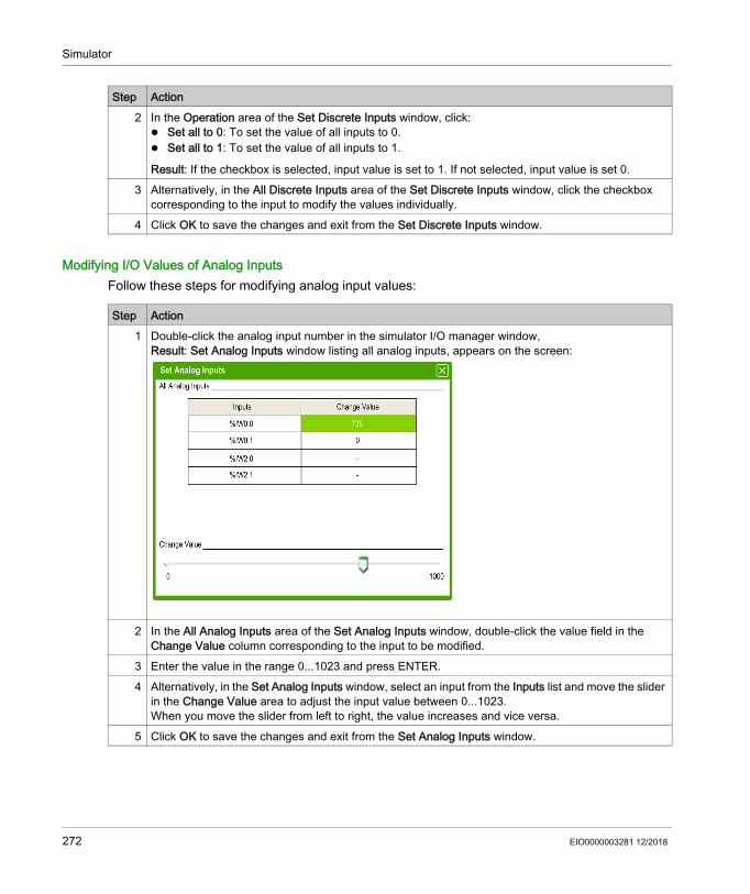
Simulator
Modifying I/O Values of Analog InputsFollow these steps for modifying analog input values:
2 In the Operation area of the Set Discrete Inputs window, click: Set all to 0: To set the value of all inputs to 0. Set all to 1: To set the value of all inputs to 1.
Result: If the checkbox is selected, input value is set to 1. If not selected, input value is set 0.3 Alternatively, in the All Discrete Inputs area of the Set Discrete Inputs window, click the checkbox
corresponding to the input to modify the values individually.4 Click OK to save the changes and exit from the Set Discrete Inputs window.
Step Action
Step Action1 Double-click the analog input number in the simulator I/O manager window,
Result: Set Analog Inputs window listing all analog inputs, appears on the screen:
2 In the All Analog Inputs area of the Set Analog Inputs window, double-click the value field in the Change Value column corresponding to the input to be modified.
3 Enter the value in the range 0...1023 and press ENTER.4 Alternatively, in the Set Analog Inputs window, select an input from the Inputs list and move the slider
in the Change Value area to adjust the input value between 0...1023.When you move the slider from left to right, the value increases and vice versa.
5 Click OK to save the changes and exit from the Set Analog Inputs window.
272 EIO0000003281 12/2018
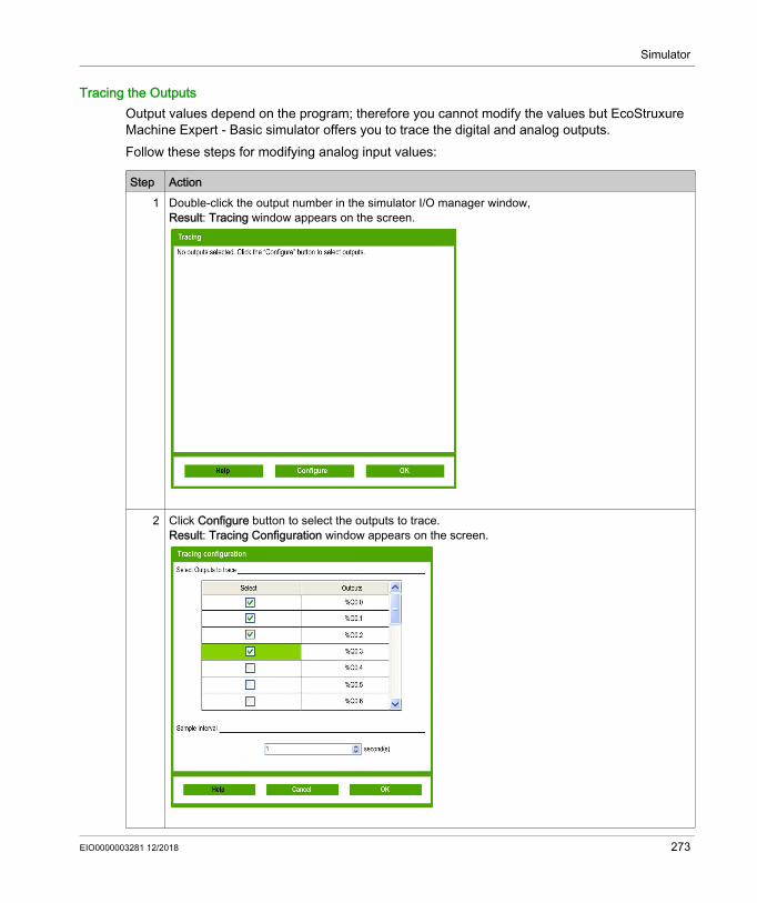
Simulator
Tracing the OutputsOutput values depend on the program; therefore you cannot modify the values but EcoStruxure Machine Expert - Basic simulator offers you to trace the digital and analog outputs.Follow these steps for modifying analog input values:
Step Action1 Double-click the output number in the simulator I/O manager window,
Result: Tracing window appears on the screen.
2 Click Configure button to select the outputs to trace.Result: Tracing Configuration window appears on the screen.
EIO0000003281 12/2018 273

Simulator
3 In the Select checkbox column, click the checkboxes corresponding to the outputs to trace.4 Select the Sample Interval from the drop-down menu to set the sample time interval for output tracing: 1 second 5 seconds 10 seconds 20 seconds
5 Click Ok to save and exit from the Tracing Configuration window.Result: Selected outputs are added to the Tracing window that displays tracing of the outputs with simulated values:
6 Click OK to exit from the Tracing window.
Step Action
274 EIO0000003281 12/2018

Simulator
How to Use the EcoStruxure Machine Expert - Basic Simulator
ProcedureFollow these steps to run the EcoStruxure Machine Expert - Basic Simulator to test your program:
Step Action1 Ensure that you have a valid program by checking the status message in the status area (for more
information, refer to Status Area (see page 47)). The program status should be No errors.You can also run EcoStruxure Machine Expert - Basic simulator when the program status is Advice.
2 Launch the simulator (refer to Accessing the Simulator (see page 264)).3 Run the controller.
In the Commissioning window, select Connect in the commissioning tree and then click Run controller button in the commissioning task area.
4 Command your program using the simulator main window (refer to Control Buttons (see page 269)).5 Check the LED status in the simulator main window (refer to LED Display (see page 267)).6 Check the status of the inputs/outputs in the simulator I/O manager window (refer to Input/Output
Status (see page 267)).7 Check the LED status in the simulator I/O manager window (refer to LED Status (see page 266)).8 Modify the I/O values as required (refer to Modifying Values Using the Simulator (see page 271)).9 Trace the outputs as required (refer to Tracing the Outputs (see page 273)).
10 Stop the controller.In the Commissioning window, select Connect in the commissioning tree and then click Stop controller button in the commissioning task area.
11 Stop the simulator.In the Commissioning window, select Connect in the commissioning tree and then click Stop controller button in the commissioning task area or press CTRL+W to exit from the simulator.
EIO0000003281 12/2018 275

Simulator
Launching Simulation in Vijeo-Designer
ProcedurePrior to launching the HMI simulation in Vijeo-Designer, first start the logic controller simulator in EcoStruxure Machine Expert - Basic (see page 264).Follow these steps to launch the simulation in Vijeo-Designer:
Step Action1 Start Vijeo-Designer.2 Open the Vijeo-Designer project that contains the symbols from an EcoStruxure Machine
Expert - Basic project.
NOTE: If the Vijeo-Designer project does not exist, create a project in Vijeo-Designer and share the symbols with the EcoStruxure Machine Expert - Basic project. For more information, refer to Sharing Symbols Between an EcoStruxure Machine Expert - Basic Project and an Vijeo-Designer Project (see page 163).
3 Click the Project tab in the Navigator window, right-click the equipment node under the IO Manager node, and select Configuration.Result: The Equipment Configuration window opens.
4 Enter the IP Address and click OK.
NOTE: The IP address must be a local host address or local address of your PC. For example, 127.0.0.1
5 Start Device Simulation Tool.6 Click the Variables tab and select the check boxes of the variables to include in the simulation.
NOTE: If the View All icon is selected, all variables selected in the Variables tab are displayed in the Simulation tab.
7 Click the Simulation tab.8 Select a variable, select an operation for the variable, and then select the Active check box.
NOTE: Only one simulation operation can be applied to any given variable at a time.
9 Define the parameters of the variable simulation operation.10 Click the Simulation icon to start the simulation.11 Change the variable values as required during the simulation:
For a slider operation, you can change the value by moving the slider, moving the wheel on your mouse, or typing the arrow keys on the keyboard.
For a toggle operation, click Set or Reset to write the corresponding string to the variable.
12 Click the Simulation icon again to stop the simulation.13 Press CTRL+Z to exit the Device Simulation Tool.
276 EIO0000003281 12/2018
EcoStruxure Machine Expert - BasicSaving Projects and Closing EcoStruxure Machine Expert - BasicEIO0000003281 12/2018
Saving Projects and Closing EcoStruxure Machine Expert - Basic
Chapter 8Saving Projects and Closing EcoStruxure Machine Expert - Basic
What Is in This Chapter?This chapter contains the following topics:
Topic PageSaving a Project 278Saving a Project As a Template 279Closing EcoStruxure Machine Expert - Basic 280
EIO0000003281 12/2018 277
Saving Projects and Closing EcoStruxure Machine Expert - Basic
Saving a Project
OverviewEcoStruxure Machine Expert - Basic projects can be saved as files to the local PC. This file has the extension *.smbp and contains:
The source code of the program contained on the Programming tab The current hardware configuration contained on the Configuration tab Settings and preferences set in the EcoStruxure Machine Expert - Basic project.
Saving the Project
Saving the Project with a Different Name
Step Action1
Click Save on the toolbar, or press Ctrl-S
2 If this is the first time you have saved the project, browse and select the folder in which to store the project file.
3 Type the name of the project file and click Save.
Step Action1
Click the menu arrow next to the Save button on the toolbar and choose Save as.2 Browse and select the folder in which to store the project file.3 Type the new name of the project file and click Save.
278 EIO0000003281 12/2018

Saving Projects and Closing EcoStruxure Machine Expert - Basic
Saving a Project As a Template
OverviewEcoStruxure Machine Expert - Basic projects can be saved as templates. The project is then listed on the Templates tab of the Start Menu. You can then use the project as the starting point for new projects.
Saving a Project as a Template
Step Action1
Click the menu arrow next to the Save button on the toolbar and choose Save as template. By default, templates are saved to the folder: C:\Users\Public\EcoStruxure Machine Expert - Basic\Examples.
2 Type the name of the project.3 Choose Sample Project Files (*.smbe) as the file Type and click Save.
EIO0000003281 12/2018 279

Saving Projects and Closing EcoStruxure Machine Expert - Basic
Closing EcoStruxure Machine Expert - Basic
OverviewTo exit EcoStruxure Machine Expert - Basic, click the Close button in the top right-hand corner of the EcoStruxure Machine Expert - Basic window.You can also click Exit on the Start Menu.
280 EIO0000003281 12/2018

EcoStruxure Machine Expert - Basic
EIO0000003281 12/2018
Appendices
What Is in This Appendix?The appendix contains the following chapters:
Chapter Chapter Name PageA Converting Twido Projects to EcoStruxure Machine Expert - Basic 283B EcoStruxure Machine Expert - Basic Keyboard Shortcuts 293
EIO0000003281 12/2018 281

282 EIO0000003281 12/2018

EcoStruxure Machine Expert - BasicConverting Twido ProjectsEIO0000003281 12/2018
Converting Twido Projects to EcoStruxure Machine Expert - Basic
Appendix AConverting Twido Projects to EcoStruxure Machine Expert - Basic
Converting Twido Projects to EcoStruxure Machine Expert - Basic
OverviewWhen you open a TwidoSoft or TwidoSuite (see page 37) project, it is automatically converted to an EcoStruxure Machine Expert - Basic project associated with a M221 logic controller reference. After the association is made, you can change the M221 Logic Controller reference (see page 62). A conversion report is generated listing any aspects of the TwidoSoft or TwidoSuite project that could not be automatically converted to the equivalent EcoStruxure Machine Expert - Basic functionality.The following provides additional conversion information.
WARNINGUNINTENDED EQUIPMENT OPERATION Always verify that your application program operates as it did prior to the conversion, having
all the correct configurations, parameters, parameter values, functions, and function blocks as required.
Modify the application as necessary such that it conforms to its previous operation. Thoroughly test and validate the newly compiled version prior to putting your application into
service.Failure to follow these instructions can result in death, serious injury, or equipment damage.
EIO0000003281 12/2018 283

Converting Twido Projects
Twido Program Types Requiring Manual AdaptionThis table lists Twido project types that use functionality with no direct equivalent on the M221 Logic Controller and provides some advice on converting these projects for EcoStruxure Machine Expert - Basic:
Twido Program Type Solution DescriptionProgram using CANopen Consider converting the program
to use the Ethernet network. Refer to the M221_with_LXM32_Modbus_TCP and M221_with_ILx2T_Modbus_TCP templates (perform a search in the Templates window (see page 38)).
Program using Twido Macro Comm
The Twido code is automatically converted to use EXCH instructions.Consider modifying the program to use Communication function blocks (see EcoStruxure Machine Expert - Basic, Generic Functions Library Guide).
Refer to the xSample_twido_macro_COMM_Conversion project template and associated documentation (perform a search in the Templates window (see page 38)) to help you modify the converted program to use Communication function blocks.
Program using Twido drive macros Parts of the Twido code cannot be automatically converted to Ladder language code.
Refer to the xSample_ATV Modbus SL_M221 or xSample_Twido_Macro_Drive_Conversion project templates to help you adapt drive management functionality.
Twido Extreme TWDLEDCK1 project
This type of project cannot be automatically converted.
To retrieve a part of the program: Change the controller in the TwidoSuite
program from TWDLEDCK1 to a different Twido controller
Convert the updated project
Program using the Remote Link Protocol
Consider modifying the program to use the following M221 Logic Controller features: Modbus TCP mapping on the
Ethernet network Modbus serial protocol using
Communication function blocks (see EcoStruxure Machine Expert - Basic, Generic Functions Library Guide)
The Remote Link protocol allows the use of a Twido controller as a remote I/O module on a serial line.
284 EIO0000003281 12/2018

Converting Twido Projects
Messages Listed in the Conversion ReportThe following table provides additional information for specific message IDs referenced in the conversion report:
Message ID Message Description/SolutionError MessagesTC-001 Impossible to load the Twido project The Twido project file could not be opened in
EcoStruxure Machine Expert - Basic.TC-002 The folder containing Twido information
(with the same name and location as the .xpr file) was not found
The specified folder could not be found.
TC-003 Twido File <filename> is not in the correct format
The Twido project is not in the correct format, nothing is converted.
TC-004 Twido File <filename> has an unexpected format
The Twido project is incomplete, nothing is converted.
TC-005 Device <device> is not supported The Twido reference <device> is not supported. Nothing is converted.
TC-006 CANopen macro has not been translated into IL
As the M221 Logic Controller does not support CANopen, Twido CANopen macros are not supported.
Advisory MessagesTC-101 The Serial Line 2 Physical medium has
been changed to RS485On TM221M•••• references, Serial Line 2 cannot be configured in RS232.Consider configuring your external device in RS485 instead. Alternatively, you can add an external RS232/RS485 adapter, replace the logic controller with a TM221C•••• reference, or add a TMC2 cartridge that supports RS232 to the controller.
TC-102 The Remote Link configuration on the Serial Line has been replaced by the Modbus protocol.
The Remote Link protocol is not supported on the M221 Logic Controller.Other solutions are possible, for example, using Communication function blocks on Modbus, or a Modbus mapping table if using an M221 Logic Controller that has Ethernet. Also refer to the information provided in Twido Program Types Requiring Manual Adaption (see page 284)
TC-103 TWDXCPODC expansion is not supported in EcoStruxure Machine Expert - Basic. It has not been imported.
TWDXCPODC is an expansion module for a display that is not supported in EcoStruxure Machine Expert - Basic.For the M221 Logic Controller, you can use the TMH2GDB Remote Graphic Display which provides an operator interface application.
EIO0000003281 12/2018 285

Converting Twido Projects
TC-104 TWDXCPODM expansion is not supported in EcoStruxure Machine Expert - Basic. It has not been imported.
TWDXCPODM is an expansion module for a display that is not supported in EcoStruxure Machine Expert - Basic.For the M221 Logic Controller, you can use the TMH2GDB Remote Graphic Display which provides an operator interface application.
TC-105 New logic controller <reference> does not support Pulse (PLS) or Pulse Width Modulation (PWM)
The Twido Compact Base 40 I/O, 240 Vac Controller had 2 transistor fast outputs. In the M221 Logic Controller range, only 24 Vdc-powered controllers have transistor outputs. The M221 Vac-powered controllers have only relay outputs. If replacing controllers, choose a M221 Logic Controller with a 24 Vdc power supply.
TC-106 CANopen communication expansion is not supported in EcoStruxure Machine Expert - Basic. It has not been imported.
The M221 Logic Controller does not support CANopen.If you need CANopen, use a Modicon M241 Logic Controller. Alternatively, replace the communication bus with Modbus on serial line or Modbus TCP on Ethernet.
TC-107 AS-Interface master expansion is not supported in EcoStruxure Machine Expert - Basic. It has not been imported.
The M221 Logic Controller does not provide an AS-Interface Master module.Consider using an Ethernet-AS Interface gateway, or use remote I/O using the Modbus serial, Modbus TCP, or EtherNet/IP protocols.
TC-108 TM200 HSC expansion is not supported in EcoStruxure Machine Expert - Basic. It has not been imported.
The M221 Logic Controller has 4 fast inputs that can be associated with High Speed Counters.
TC-109 TWD PTO expansion is not supported in EcoStruxure Machine Expert - Basic. It has not been imported.
The M221 Logic Controller references without relay outputs have 2 or 4 fast outputs that can be associated with Pulse Train Outputs.
TC-110 TM2 VCM expansion is not supported in EcoStruxure Machine Expert - Basic. It has not been imported.
TM2 VCM expansion modules are not supported in EcoStruxure Machine Expert - Basic.
TC-111 Timer 3 “Adjustable” parameter is not supported in EcoStruxure Machine Expert - Basic. It has been forced to True
In EcoStruxure Machine Expert - Basic function blocks, this parameter is not supported.
TC-112 %QA ASi outputs are not supported in EcoStruxure Machine Expert - Basic.
These addresses were reserved for the management of AS-Interface remote I/Os. As with the AS-Interface Master module, these addresses are not supported on the M221 Logic Controller.
Message ID Message Description/Solution
286 EIO0000003281 12/2018

Converting Twido Projects
TC-113 The Auto-tune on PID has changed; the new parameter AT Trigger of the PID Autotune (AT) tab has been added and configured and the parameter ‘Output setpoint’ has been ignored.
In EcoStruxure Machine Expert - Basic, configure PID auto-turning.
TC-114 The input used by HSCn (in Twido: VFCn) changed from <input1> to <input2>.
Verify whether your program uses the input assigned.
TC-115 The inputs used by HSCn <input1> and <input2> are inverted relative to Twido VFCn.
HSC inputs <input1> and <input2> on Twido VFC controllers are inverted in EcoStruxure Machine Expert - Basic; revert the inputs in the application.
TC-116 The Free POU <x> is already assigned to <y>. The <z> event cannot use this Free POU.
Assign the Free POU to a different event.
TC-117 <x> Twido object has been moved to <y> on new controllers. You must update your program to maintain consistency.
The object has been converted to an EcoStruxure Machine Expert - Basic object with similar functionality. <y> can be a system bit, system word, or a different object type such as %IWS.
TC-118 <x> Twido object has been modified on new controllers. You must verify if your controller is still consistent.
The object has been converted, but its functionality in EcoStruxure Machine Expert - Basic may be different. Refer to the online help for assistance in updating your program.
TC-119 <x> Twido object is no longer supported on new controllers. You must update your program using new functionalities.
The object has no equivalent in EcoStruxure Machine Expert - Basic. Refer to the online help for assistance in updating your program.
TC-120 The source controller is powered by 24 Vdc but the target controller <reference> is powered by 100...240 Vac.
The converted M221 Logic Controller does not have the same power supply, but there is no impact on the application.
TC-121 The source controller <reference1> with transistor and relay outputs has been converted to <reference2> with transistor outputs only.
The converted M221 Logic Controller does not have the same output types. The conversion allows the application to remain unchanged.
TC-122 Invalid syntax for symbol <x> associated with <y>.
Correct the syntax of the specified symbol.
TC-123 Symbol ‘<x>’ associated with <y> is a reserved word and has been converted to <z>.
EcoStruxure Machine Expert - Basic has new instructions compared to TwidoSuite/TwidoSoft. Reserved words are converted to <z>.
Message ID Message Description/Solution
EIO0000003281 12/2018 287

Converting Twido Projects
TC-124 <w> time base configured in <x> has been converted to <y>. You may have to adjust accordingly the preset in the configuration and <w>.<z> in the application.
This message occurs when converting an application using PLS or PWM. On Twido, the hardware time bases are 0.142 ms and 0.57 ms. On the M221 Logic Controller, the hardware time bases are 0.1 ms and 1 ms, respectively. For the PLS and PWM function blocks, the period of the generated signal is the time base multiplied by the preset value (PLS.P, PLS.PD, or PWM.P). Preset values (.P or .PD) may have to be adjusted in both the configuration and the program.
TC-125 <x> configured in <y> has been converted in <z>.
The M221 Logic Controller does not support HSC in "down counting" mode. These configurations are converted to "simple counting" mode (that is, up counting) in EcoStruxure Machine Expert - Basic.
TC-126 Threshold values for <x> have been modified as they must not be equal to each other.
In EcoStruxure Machine Expert - Basic, it is not possible to have identical threshold values.If the Twido application does not use the thresholds (no associated event or reflex configured), the values are modified to avoid configuration errors.
TC-127 Threshold values for <x> are equal and will result in a configuration error.
In EcoStruxure Machine Expert - Basic, it is not possible to have identical threshold values.If the Twido application uses the thresholds, nothing is changed, resulting in a configuration error. Modify the application to correct the error.
TC-128 <x> is configured as both Run/Stop and event trigger in Twido project, creating a conflict in EcoStruxure Machine Expert - Basic; the Run/Stop feature has been deconfigured.
In EcoStruxure Machine Expert - Basic, it is not possible to have the same input configured in 2 different functions at the same time.
TC-129 An Ethernet module has been detected on a Twido reference with embedded Ethernet port. The Ethernet module configuration will be ignored.
In EcoStruxure Machine Expert - Basic, it is not possible to have two Ethernet links.
TC-130 A Twido macro cannot be called from a subroutine. The macro called from SRn rung <x> has not been converted.
In EcoStruxure Machine Expert - Basic, it is not possible to call a macro from a subroutine.
TC-131 Unable to convert all event priorities. Manual adjustment is required.
The conversion process was not able to set all event priorities.
TC-132 Unable to convert macro <macro>: maximum number of subroutines are used.
The Twido project already uses the maximum number of subroutines, which have been converted to Free POUs.The macro conversion process may require additional Free POUs.
Message ID Message Description/Solution
288 EIO0000003281 12/2018
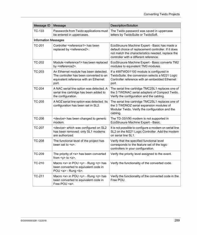
Converting Twido Projects
TC-133 Passwords from Twido applications must be entered in uppercases.
The Twido password was saved in uppercase letters by TwidoSuite or TwidoSoft.
Information MessagesTC-201 Controller <reference1> has been
replaced by <reference2>.EcoStruxure Machine Expert - Basic has made a default choice of replacement controller. If it does not match the characteristics needed, replace the controller with a different reference.
TC-202 Module <reference1> has been replaced by <reference2>.
EcoStruxure Machine Expert - Basic converts TM2 modules to equivalent TM3 modules.
TC-203 An Ethernet module has been detected. The controller has been converted to an equivalent reference with an Ethernet port.
If a 499TWD01100 module is configured in TwidoSuite, the conversion selects a M221 Logic Controller reference with an embedded Ethernet port.
TC-204 A NAC serial line option was detected. A serial line cartridge has been added to the configuration.
The serial line cartridge TMC2SL1 replaces one of the 3 TWDNAC serial adapters of Compact Twido. Verify the configuration and the cabling.
TC-205 A NOZ serial line option was detected. Its configuration has been set in SL2.
The serial line cartridge TMC2SL1 replaces one of the 3 TWDNOZ serial expansion modules of Modular Twido. Verify the configuration and the cabling.
TC-206 <device> has been changed to generic modem.
The TD-33/V90 modem is not supported in EcoStruxure Machine Expert - Basic.
TC-207 <device> which was configured on SL2 has been removed; only SL1 modems are authorized.
It is not possible to configure a modem on serial line SL2 on the M221 Logic Controller. Add the modem on serial line SL1.
TC-208 The functional level of the project has been set to <x>.
Verify that the specified functional level corresponds to the feature set of the logic controllers in your configuration.
TC-209 The priority of <x> has been converted from <y> to <z>.
Verify the priority level assigned to the event.
TC-210 Macro <x> in POU <y> - Rung <z> has been converted to equivalent code in POU <a> - Rung <b>.
Verify the functionality of the converted code.
TC-211 Macro <x> in POU <y> - Rung <z> has been converted to equivalent code in Free POU <a>.
Verify the functionality of the converted code in the Free POU.
Message ID Message Description/Solution
EIO0000003281 12/2018 289
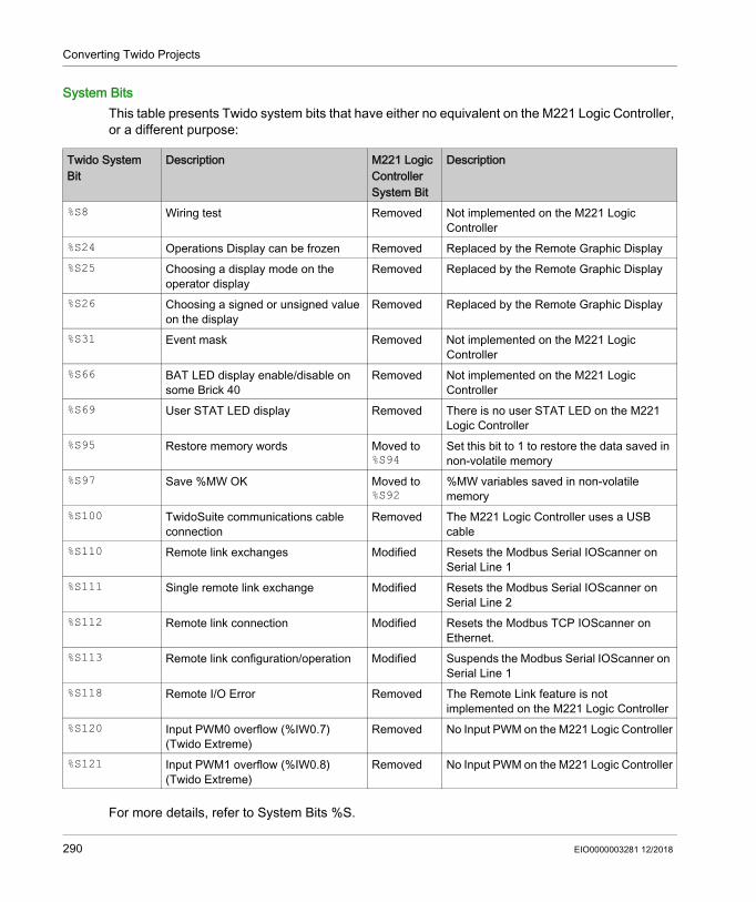
Converting Twido Projects
System BitsThis table presents Twido system bits that have either no equivalent on the M221 Logic Controller, or a different purpose:
For more details, refer to System Bits %S.
Twido System Bit
Description M221 Logic Controller System Bit
Description
%S8 Wiring test Removed Not implemented on the M221 Logic Controller
%S24 Operations Display can be frozen Removed Replaced by the Remote Graphic Display%S25 Choosing a display mode on the
operator displayRemoved Replaced by the Remote Graphic Display
%S26 Choosing a signed or unsigned value on the display
Removed Replaced by the Remote Graphic Display
%S31 Event mask Removed Not implemented on the M221 Logic Controller
%S66 BAT LED display enable/disable on some Brick 40
Removed Not implemented on the M221 Logic Controller
%S69 User STAT LED display Removed There is no user STAT LED on the M221 Logic Controller
%S95 Restore memory words Moved to %S94
Set this bit to 1 to restore the data saved in non-volatile memory
%S97 Save %MW OK Moved to %S92
%MW variables saved in non-volatile memory
%S100 TwidoSuite communications cable connection
Removed The M221 Logic Controller uses a USB cable
%S110 Remote link exchanges Modified Resets the Modbus Serial IOScanner on Serial Line 1
%S111 Single remote link exchange Modified Resets the Modbus Serial IOScanner on Serial Line 2
%S112 Remote link connection Modified Resets the Modbus TCP IOScanner on Ethernet.
%S113 Remote link configuration/operation Modified Suspends the Modbus Serial IOScanner on Serial Line 1
%S118 Remote I/O Error Removed The Remote Link feature is not implemented on the M221 Logic Controller
%S120 Input PWM0 overflow (%IW0.7) (Twido Extreme)
Removed No Input PWM on the M221 Logic Controller
%S121 Input PWM1 overflow (%IW0.8) (Twido Extreme)
Removed No Input PWM on the M221 Logic Controller
290 EIO0000003281 12/2018
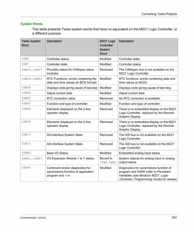
Converting Twido Projects
System WordsThis table presents Twido system words that have no equivalent on the M221 Logic Controller, or a different purpose:
Twido System Word
Description M221 Logic Controller System Word
Description
%SW6 Controller status Modified Controller state%SW7 Controller state Modified Controller status%SW20...%SW27 Provides status for CANopen slave
modulesRemoved The CANopen bus is not available on the
M221 Logic Controller%SW49...%SW53 RTC Functions: words containing the
date and time values (in BCD format)Modified RTC functions: words containing date and
time values (in BCD).%SW58 Displays code giving cause of last stop Modified Displays code giving cause of last stop.%SW59 Adjust current date Modified Adjust current date.%SW60 RTC correction value Removed No RTC correction is available.%SW67 Function and type of controller Modified Function and type of controller.%SW68 Elements displayed on the 2-line
operator displayRemoved There is no embedded display on the M221
Logic Controller, replaced by the Remote Graphic Display.
%SW69 Elements displayed on the 2-line operator display
Removed There is no embedded display on the M221 Logic Controller, replaced by the Remote Graphic Display.
%SW73 AS-Interface System State Removed The ASI bus is not available on the M221 Logic Controller.
%SW74 AS-Interface System State Removed The ASI bus is not available on the M221 Logic Controller.
%SW80 Base I/O Status Modified Embedded analog input status%SW81...%SW87 I/O Expansion Module 1 to 7 status Moved to
%IWS, %QWSSystem objects for analog input or analog output status
%SW96 Command and/or diagnostics for save/restore function of application program and %MW
Modified Diagnostics for save/restore function of program and %MW (refer to Persistent Variables (see Modicon M221, Logic Controller, Programming Guide) for details)
EIO0000003281 12/2018 291
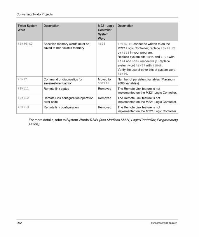
Converting Twido Projects
For more details, refer to System Words %SW (see Modicon M221, Logic Controller, Programming Guide).
%SW96:X0 Specifies memory words must be saved to non-volatile memory
%S93 %SW96:X0 cannot be written to on the M221 Logic Controller; replace %SW96:X0 by %S93 in your program.Replace system bits %S95 and %S97 with %S94 and %S92 respectively. Replace system word %SW97 with %SW48.Verify the use of other bits of system word %SW96.
%SW97 Command or diagnostics for save/restore function
Moved to %SW148
Number of persistent variables (Maximum 2000 variables)
%SW111 Remote link status Removed The Remote Link feature is not implemented on the M221 Logic Controller.
%SW112 Remote Link configuration/operation error code
Removed The Remote Link feature is not implemented on the M221 Logic Controller.
%SW113 Remote link configuration Removed The Remote Link feature is not implemented on the M221 Logic Controller.
Twido System Word
Description M221 Logic Controller System Word
Description
292 EIO0000003281 12/2018

EcoStruxure Machine Expert - BasicEcoStruxure Machine Expert - Basic Keyboard ShortcutsEIO0000003281 12/2018
EcoStruxure Machine Expert - Basic Keyboard Shortcuts
Appendix BEcoStruxure Machine Expert - Basic Keyboard Shortcuts
EcoStruxure Machine Expert - Basic Keyboard Shortcuts
Keyboard Shortcuts List
Modifier Key Command View ConditionCTRL C Copy Textbox –CTRL V Paste Textbox –CTRL X Cut Textbox –ALT Left Go to previous tab All –ALT Right Go to following tab All –
F1 Show help or contextual help All Selection in System Settings → GeneralSHIFT F1
ALT F4 Exit EcoStruxure Machine Expert - Basic
All –
CTRL B Launch simulator All –CTRL G Login All –CTRL H Logout All –CTRL L Stop controller All –CTRL M Run controller All –CTRL N New project All –CTRL O Open project All –CTRL P Print project report All –CTRL Q Exit EcoStruxure Machine
Expert - BasicAll –
CTRL S Save project All –CTRL W Stop simulator All –CTRL J Download Commissioning –CTRL K Upload Commissioning –
ALT Show Ladder shortcuts Programming –Del Delete Programming items are selected
CTRL D Convert all rungs in program to Ladder
Programming –
EIO0000003281 12/2018 293

EcoStruxure Machine Expert - Basic Keyboard Shortcuts
CTRL+ALT D Convert all rungs in program to IL
Programming –
CTRL F Search Programming –CTRL I Insert a new rung before the
selected rungProgramming –
CTRL Y Redo Programming –CTRL Z Undo Programming –CTRL Arrow key Draw line Ladder rung Drawing tool selectedCTRL Arrow key Erase line Ladder rung Erasing tool selectedCTRL Arrow key Select/unselect next ladder
cell (cell by cell)Ladder rung Selection tool selected
SHIFT Arrow key Select/unselect next ladder cells (select by area)
Ladder rung Selection tool selected
ESC Reset pointer to selection tool Ladder rung Selected tool is not draw wire or erase wire, no items are being dragged, no popup is opened
ESC Cancel the pending line Ladder rung Drawing in progressESC Cancel the erasing line Ladder rung Erasing in progressESC Cancel move selected item(s)
(restore initial position)Ladder rung Ladder items are being
draggedESC Close suggestion’s list Ladder rung A suggestions list is opened
(like the available descriptors for a contact)
ESC Close menu item of ladder toolbar
Ladder rung A menu of the ladder toolbar is opened (like function blocks)
ENTER Start/stop moving ladder elements
Ladder rung At least one selected cell
Arrow key Move floating cell Ladder rung Moving cell startedArrow key Change current cell Ladder rung By defaultF5 Open contact Ladder rung Asian set 1 ladder toolbarF6 Open branch Ladder rung Asian set 1 ladder toolbar
SHIFT F5 Close contact Ladder rung Asian set 1 ladder toolbarSHIFT F6 Close branch Ladder rung Asian set 1 ladder toolbar
F7 Coil Ladder rung Asian set 1 ladder toolbarCTRL F7 Negated coil Ladder rung Asian set 1 ladder toolbarCTRL F5 Set coil Ladder rung Asian set 1 ladder toolbar
Modifier Key Command View Condition
294 EIO0000003281 12/2018
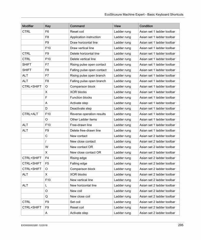
EcoStruxure Machine Expert - Basic Keyboard Shortcuts
CTRL F6 Reset coil Ladder rung Asian set 1 ladder toolbarF8 Application instruction Ladder rung Asian set 1 ladder toolbarF9 Draw horizontal line Ladder rung Asian set 1 ladder toolbarF10 Draw vertical line Ladder rung Asian set 1 ladder toolbar
CTRL F9 Delete horizontal line Ladder rung Asian set 1 ladder toolbarCTRL F10 Delete vertical line Ladder rung Asian set 1 ladder toolbarSHIFT F7 Rising pulse open contact Ladder rung Asian set 1 ladder toolbarSHIFT F8 Falling pulse open contact Ladder rung Asian set 1 ladder toolbarALT F7 Rising pulse open branch Ladder rung Asian set 1 ladder toolbarALT F8 Falling pulse open branch Ladder rung Asian set 1 ladder toolbarCTRL+SHIFT O Comparison block Ladder rung Asian set 1 ladder toolbar
X XOR blocks Ladder rung Asian set 1 ladder toolbarF Function blocks Ladder rung Asian set 1 ladder toolbarA Activate step Ladder rung Asian set 1 ladder toolbarD Deactivate step Ladder rung Asian set 1 ladder toolbar
CTRL+ALT F10 Reverse operation results Ladder rung Asian set 1 ladder toolbarO Other Ladder items Ladder rung Asian set 1 ladder toolbar
ALT F10 Free-drawn line Ladder rung Asian set 1 ladder toolbarALT F9 Delete free-drawn line Ladder rung Asian set 1 ladder toolbar
C New contact Ladder rung Asian set 2 ladder toolbar/ New close contact Ladder rung Asian set 2 ladder toolbarW New contact OR Ladder rung Asian set 2 ladder toolbarX New close contact OR Ladder rung Asian set 2 ladder toolbar
CTRL+SHIFT F4 Rising edge Ladder rung Asian set 2 ladder toolbarCTRL+SHIFT F5 Falling edge Ladder rung Asian set 2 ladder toolbarCTRL+SHIFT O Comparison block Ladder rung Asian set 2 ladder toolbarALT X XOR blocks Ladder rung Asian set 2 ladder toolbar
F10 New vertical line Ladder rung Asian set 2 ladder toolbarALT L New horizontal line Ladder rung Asian set 2 ladder toolbar
O New coil Ladder rung Asian set 2 ladder toolbarQ New close coil Ladder rung Asian set 2 ladder toolbar
CTRL F9 Set coil Ladder rung Asian set 2 ladder toolbarCTRL+SHIFT F9 Reset coil Ladder rung Asian set 2 ladder toolbar
A Activate step Ladder rung Asian set 2 ladder toolbar
Modifier Key Command View Condition
EIO0000003281 12/2018 295

EcoStruxure Machine Expert - Basic Keyboard Shortcuts
D Deactivate step Ladder rung Asian set 2 ladder toolbarI New instruction Ladder rung Asian set 2 ladder toolbarF New function block Ladder rung Asian set 2 ladder toolbar
ALT O Other Ladder items Ladder rung Asian set 2 ladder toolbarF2 Deactivate branching mode Ladder rung European or American
ladder toolbarSHIFT F2 Activate branching mode Ladder rung European or American
ladder toolbarSHIFT F3 Normally open contact Ladder rung European ladder toolbarSHIFT F4 Normally close contact Ladder rung European ladder toolbarCTRL+SHIFT F4 Rising edge Ladder rung European ladder toolbarCTRL+SHIFT F5 Falling edge Ladder rung European ladder toolbarCTRL+SHIFT 6 Operation block Ladder rung European ladder toolbarCTRL+SHIFT O Comparison block Ladder rung European ladder toolbar
X XOR blocks Ladder rung European ladder toolbarSHIFT F7 Assignment Ladder rung European ladder toolbarCTRL+SHIFT F9 Negated coil Ladder rung European ladder toolbar
F9 Set coil Ladder rung European ladder toolbarSHIFT F9 Reset coil Ladder rung European ladder toolbar
A Activate step Ladder rung European ladder toolbarD Deactivate step Ladder rung European ladder toolbar
SHIFT F5 Function block Ladder rung European ladder toolbarCTRL+SHIFT F6 Operation block Ladder rung European ladder toolbar
F3 Line Ladder rung European ladder toolbarF3 Draw wire line Ladder rung European ladder toolbarF4 Erase wire line Ladder rung European ladder toolbarO Other Ladder items Ladder rung European ladder toolbar
SHIFT F2 Activate branching mode Ladder rung EcoStruxure Machine Expert - Basic toolbar
F2 Deactivate branching mode Ladder rung EcoStruxure Machine Expert - Basic toolbar
F3 Draw wire line Ladder rung EcoStruxure Machine Expert - Basic toolbar
SHIFT F3 Erase wire line Ladder rung EcoStruxure Machine Expert - Basic toolbar
Modifier Key Command View Condition
296 EIO0000003281 12/2018

EcoStruxure Machine Expert - Basic Keyboard Shortcuts
F4 Normal contact Ladder rung EcoStruxure Machine Expert - Basic toolbar
SHIFT F4 Negated contact Ladder rung EcoStruxure Machine Expert - Basic toolbar
CTRL F9 Coil Ladder rung EcoStruxure Machine Expert - Basic toolbar
CTRL+SHIFT F9 Negative coil Ladder rung EcoStruxure Machine Expert - Basic toolbar
F9 Set Coil Ladder rung EcoStruxure Machine Expert - Basic toolbar
SHIFT F9 Reset Coil Ladder rung EcoStruxure Machine Expert - Basic toolbar
CTRL+SHIFT F4 Rising edge Ladder rung EcoStruxure Machine Expert - Basic toolbar
CTRL+SHIFT F5 Falling edge Ladder rung EcoStruxure Machine Expert - Basic toolbar
CTRL+SHIFT {6, 7} Operation Block Ladder rung EcoStruxure Machine Expert - Basic toolbar
CTRL+SHIFT {O, P} Comparison Block Ladder rung EcoStruxure Machine Expert - Basic toolbar
X or ALT+X XOR blocks Ladder rung EcoStruxure Machine Expert - Basic toolbar
O or ALT+O Other Ladder items Ladder rung EcoStruxure Machine Expert - Basic toolbar
A or ALT+A Activate step Ladder rung EcoStruxure Machine Expert - Basic toolbar
D or ALT+D Deactivate step Ladder rung EcoStruxure Machine Expert - Basic toolbar
Modifier Key Command View Condition
EIO0000003281 12/2018 297

EcoStruxure Machine Expert - Basic Keyboard Shortcuts
298 EIO0000003281 12/2018

EcoStruxure Machine Expert - BasicGlossaryEIO0000003281 12/2018
Glossary
!%S
According to the IEC standard, %S represents a system bit.
%SWAccording to the IEC standard, %SW represents a system word.
Aanimation table
A software table that displays the real-time values of objects such as input bits and memory words. When EcoStruxure Machine Expert - Basic is connected to a logic controller, the values of certain object types in animation tables can be forced to specific values. Animation tables are saved as part of EcoStruxure Machine Expert - Basic applications.
applicationA program including configuration data, symbols, and documentation.
Cconfiguration
The arrangement and interconnection of hardware components within a system and the hardware and software parameters that determine the operating characteristics of the system.
Fflash memory
A non-volatile memory that can be overwritten. It is stored on a special EEPROM that can be erased and reprogrammed.
Free POUA programmable object unit (POU), typically containing library functions, that can be programmed and updated independently of the master task of a program. Free POUs are available to be called from within programs as subroutines or jumps. For example, the periodic task is a subroutine that is implemented as a Free POU.
EIO0000003281 12/2018 299

Glossary
GGRAFCET
The functioning of a sequential operation in a structured and graphic form.This is an analytical method that divides any sequential control system into a series of steps, with which actions, transitions, and conditions are associated.
Iinstruction list language
A program written in the instruction list language that is composed of a series of text-based instructions executed sequentially by the controller. Each instruction includes a line number, an instruction code, and an operand (see IEC 61131-3).
Lladder diagram language
A graphical representation of the instructions of a controller program with symbols for contacts, coils, and blocks in a series of rungs executed sequentially by a controller (see IEC 61131-3).
Mmaster task
A processor task that is run through its programming software. The master task has 2 sections: IN: Inputs are copied to the IN section before execution of the master task. OUT: Outputs are copied to the OUT section after execution of the master task.
Nnon-program data
Data in a EcoStruxure Machine Expert - Basic application that is not directly used by the program, such as project properties, symbols, and comments.
Ppost configuration
(post configuration) An option that allows to modify some parameters of the application without changing the application. Post configuration parameters are defined in a file that is stored in the controller. They are overloading the configuration parameters of the application.
300 EIO0000003281 12/2018
Glossary
POU(program organization unit) A variable declaration in source code and a corresponding instruction set. POUs facilitate the modular re-use of software programs, functions, and function blocks. Once declared, POUs are available to one another.
RRTC
(real-time clock) A battery-backed time-of-day and calender clock that operates continuously, even when the controller is not powered for the life of the battery.
Ssymbol
A string of a maximum of 32 alphanumeric characters, of which the first character is alphabetic. It allows you to personalize a controller object to facilitate the maintainability of the application.
symbolic addressingThe indirect method of addressing memory objects, including physical inputs and outputs, used in programming instructions as operands and parameters by first defining symbols for them using these symbols in association with the programming instructions.In contrast to immediate addressing, this is the preferred method because if the program configuration changes, symbols are automatically updated with their new immediate address associations. By contrast, any immediate addresses used as operands or parameters are not updated (refer to immediate addressing).
TTCP
(transmission control protocol) A connection-based transport layer protocol that provides a simultaneous bi-directional transmission of data. TCP is part of the TCP/IP protocol suite.
Uuser defined function
It allows you to create your own functions with one or more input parameters, local variables, and a return value. The user-defined function can then be called in operation blocks. A user-defined function is stored as part of the project and downloaded to the logic controller as part of the application.
user defined function blockIt allows you to create your own function blocks with one or more input and outputs, parameters, and local variables. User-defined function blocks are stored as part of the project.
EIO0000003281 12/2018 301

Glossary
Wwatchdog
A watchdog is a special timer used to ensure that programs do not overrun their allocated scan time. The watchdog timer is usually set to a higher value than the scan time and reset to 0 at the end of each scan cycle. If the watchdog timer reaches the preset value, for example, because the program is caught in an endless loop, an error is declared and the program stopped.
302 EIO0000003281 12/2018

EcoStruxure Machine Expert - BasicIndexEIO0000003281 12/2018
Index
Aaccumulator, 194action zone, 170addressing
symbolic, 68allocating memory in controller, 70allocation mode, 70animation tables, 139application
behavior, configuring, 77definition of, 28downloading to controller, 249protecting with a password, 55protecting with password, 58uploading from logic controller, 251whether password-protected, 260
assignment instructionsinserting in Ladder Diagram rungs, 182
Bbackup memory contents, 236bill of material (BOM), printing, 51Boolean
accumulator, 194Boolean operators
graphic elements for, 176branching modes
graphic element, 175buttons, toolbar, 45
Ccache memory, consumption of, 165catalog, 61
replacing logic controller with reference from, 62
coilsgraphic elements for, 177graphical representation of outputs, 168
EIO0000003281 12/2018
commentsadding to Instruction List, 192adding to Ladder Diagrams, 186
commissioning, 30Commissioning window, 240connecting to a logic controller, 242
communication objects, 156comparison block
graphic elements for, 176comparison blocks
inserting IL expressions in, 181comparison expression
inserting in Ladder Diagram rungs, 181compile, date and time of last, 165configuration
current, 61replacing logic controller in, 62
configuringapplication behavior, 77hardware components with Configuration window, 61master task, 116periodic task duration, 128project properties, 55tasks and scan , 82
connecting to a logic controller, 242contacts
graphic elements for, 175graphical representation of inputs, 168
controller time, displaying in trace, 226converting Twido projects to EcoStruxure Machine Expert - Basic, 283copying and pasting
Grafcet POUs, 93POU, 96
creatingFree POU, 95Grafcet POUs, 93
creating projects, 28customizing, Ladder Editor, 49
303

Index
Ddebugging in online mode, 225developing programs, stages of, 29development stages, 30digital inputs
configuring as event sources, 131downloading
firmware updates, 253user application to controller, 249
downloading non-program data, 236Drive objects, 155
Eend/jump
graphic elements, 178Ethernet
configuration using post configuration file, 260
event sourceassigning subroutine as, 134types of, 131
event tasks managing, 133configuring, 82overview, 130
eventssince last cold restart, 135triggering subroutines with, 131
EXCEPTION statefallback behavior, 79
expansion modulessupported devices, 24
exportingsymbol list, 162trace, 228
Ffallback
behavior, specifying, 79values, 79
firmware updates, 253firmware, downloading updates to controller, 253
304
forcing valuesin animation tables, 139of I/Os, 260
Free POUassigning to an event source, 134assigning to events, 98assigning to periodic task, 98
Free POUcreating, 95
Free POUfor periodic task, 126introduction to, 86
Free POUsremoving, 97
function blocksgraphic element, 177
functional levels, 80
Ggeneral settings, 49Grafcet, 203
graphical elements, 178how to use the instructions, 208instructions, 203post-processing, 207preprocessing, 204program structure, 204sequential processing, 206
Grafcet (SFC)Grafcet Graphical Editor, 214
Grafcet POUcopying and pasting, 93creating, 93removing, 94renaming, 94
graphic elementsLadder diagrams, 174
grid lines, style of in Ladder Editor, 49
Hhardware components, configuring, 61hardware tree, 61
EIO0000003281 12/2018

Index
helpchanging shortcuts, 49
Iimporting
symbol list, 161input/output objects, 151inputs
configuring as event sources, 131modifying, 187
insertingnew Grafcet POUs, 93
Instruction Listcomments, 192
instructionsupstream/downstream, 187
Kkeyboard shortcuts, 49, 293
LLadder diagrams
comments, 186graphic elements, 174introduction, 168programming principles, 170reversing to Instruction List, 71rungs, 169using parentheses in, 188
Ladder Editorcustomizing, 49defining symbols in, 69resetting pointer after insertion, 49
Ladder/List reversibility, 71language,
user interface, 49life cycle state
of logic controller, 47line
graphic element, 175List instructions, 195
EIO0000003281 12/2018
List languageoverview, 191
logic controllerdate and time last stopped, 260displaying information about, 260displaying state, 260replacing current in configuration, 62state on startup, configuring, 77supported types, 24updating firmware, 253updating RTC of, 262
Mmaintaining fallback values, 79master task
assigning POU as, 86configuring, 82, 116system bits and words controlling, 117
memory allocation, 70memory consumption, viewing, 165memory management with SD card, 254memory objects, 145minimum system requirements, 23modem
displaying status of, 260modes, operating, 31module areas, 30
Nnetwork objects, 152, 152new Grafcet POU
inserting, 93non-program data, 28, 139
downloading, 236normal scan mode, 117
Oobjects
definition of, 67network, 152to trace in animation table, 139updating values of in real time, 139
305

Index
offline modedisplayed in status area, 47overview, 31
online mode, 70animation tables in, 139debugging, 225displayed in status area, 47editing values in animation table, 141overview, 31updating RTC in, 262
operands, 194operating modes, 31operation blocks
graphic element, 178inserting assignment instructions in, 182
operationsinserting in Ladder Diagram rungs, 182
outputsmodifying, 187
Pparentheses
modifiers, 200nesting, 200using in Ladder diagrams, 188using in programs, 199
passwordprotecting an application , 58removing from application, 58removing from project, 57requiring to open project file, 57whether application is protected with, 260
password-protecting an application, 55period, scan, 117periodic
scan mode, 117scan period, 128tasks, 126
periodic taskassigning Free POU to, 98configuring, 82configuring duration of, 128
306
post configurationusing Ethernet parameters from, 260using serial line parameters from, 260
POUcopying, 96Free, 126managing with tasks, 87overview, 86pasting, 96
printing reports, 51priority level, of events, 130program
compiling, 45definition of, 28displaying number of lines in, 165jumps, 187
program development, stages of, 29program organization unit (POU), 86program, configuring fallback behaviors, 79programming
best practices, 187grid, 170languages, supported, 26workspace, 64
projectconfiguring properties, 55definition of, 28displaying report for, 51protecting with password, 57saving, 278saving as a template, 279templates, 38
projectscreating, 28
properties, 55PTO objects, 154pulse width (TON) , 117
RRAM memory
executable contains application, 260RAM memory, consumption of, 165registering EcoStruxure Machine Expert - Ba-sic software, 34
EIO0000003281 12/2018
Index
relay circuits, representing as Ladder dia-grams, 168removing
Free POUs, 97Grafcet POUs, 94
removing password protection, 57, 58renaming
a Grafcet POU, 94replacing
logic controller in configuration, 62reports
exporting, 51printing, 51
reversibilityintroduction to, 71
rollback changes, 236RTC
displaying date and time, 260managing with system bits, 187updating in controller, 262
rungscopying, 91creating, 90deleting, 92graphic element, 174inserting, 90managing, 90renaming, 92
Sscan modes, 82, 117scan task, configuring watchdog, 79scan time
displaying minimum, maximum, current, 260minimum, displayed in status area, 47
SD cardmemory management with, 254
search and replace, 157sections
in events, 130of master task, 116
selectiongraphic element, 175
EIO0000003281 12/2018
sending program modifications, 236serial line
configuration using post configuration file, 260
settingsgeneral, 49
sharingsymbol list, 163
sharing symbolswith Vijeo Designer project, 163
simulator, 264accessing the simulator, 264how to use, 275I/O manager window, 266mode, overview, 31modifying values, 271modifying values of analog inputs, 272modifying values of digital inputs, 271output tracing, 273simulator windows, 264Time Management window, 268
software objects, 153sources of events, 131stages of developing a program, 30startup state of logic controller, 77state
initial logic controller, configuring, 77of controller, displaying, 260
status area, 47stop sensors, wiring, 187STOPPED state
fallback behavior, 79subroutine
assigning to periodic task, 126assigning to tasks, 133implementing as Free POU, 86of master task, 116triggering execution with an event, 131
supported devices, 24symbol list
displaying, 160exporting, 162importing, 161sharing with Vijeo Designer project, 163
symbolic addressing, 68
307
Index
symbolsaddressing with, 68defining in graphic elements of ladder ed-itor, 69defining in Properties window, 68list of used, 160storing in logic controller, 69
system bits%S0, 187%S11, 117%S14, 260%S19, 117%S31, 135%S38, 135%S39, 135%S49, 187%S51, 187
system bits/wordscontrolling events with, 135in symbol list, 160
system objects, 150system requirements, 23system words
%SW0, 117%SW27, 117%SW30, 117%SW30...%SW32, 260%SW31, 117%SW32, 117%SW35...%SW38, 260%SW48, 135%SW54...%SW57, 260%SW58, 260%SW6, 260
Ttask
event, 130periodic, 126
tasksconfiguring, 82
templateproject, 38saving project file as, 279
308
test zone, 170TH0, TH1
configuring as event sources, 131threshold outputs (of %HSC)
configuring as event sources, 131time base (for trace), 144timer, watchdog, 79toolbar buttons, 45tools
animation tables, 139communication objects, 156Drive objects, 155input/output objects, 151memory consumption, 165memory objects, 145network objects, 152PTO objects, 154search and replace, 157software objects, 153symbols lists, 160system objects, 150using, 136
tracedisplaying, 226exporting to PDF, 228selecting objects to, 139selecting time base for, 144
Twido projects, converting to EcoStruxure Machine Expert - Basic, 283
Uuploading
application from logic controller, 251preventing with a password, 58
user interfacesetting language, 49
user-defined functionmanaging, 105programming, 101
user-defined function blockdefining, 109managing, 113programming, 110
EIO0000003281 12/2018
Index
Wwatchdog timer, configuring, 79wiring stop sensors, 187
XXOR
graphic elements for, 176
EIO0000003281 12/2018
309
Index
310 EIO0000003281 12/2018