
ECE-7th sem. CAO-Unit 6
142
ECE-7 th sem. CAO-Unit 6 Pipeline and Vector Processing Dr.E V Prasad 12.10.17
Transcript of ECE-7th sem. CAO-Unit 6

ECE-7th sem. CAO-Unit 6
Pipeline and Vector ProcessingDr.E V Prasad
12.10.17

Contents Parallel Processing Pipelining Arithmetic Pipeline Instruction Pipeline RISC Pipeline Vector Processing Array Processors
Parallel Processing Pipelining Arithmetic Pipeline Instruction Pipeline RISC Pipeline Vector Processing Array Processors

Parallel Processing

Introduction Parallel processing is a term used to denote a large class
of techniques that are used to provide simultaneousdata-processing tasks for the purpose of increasingthe computational speed of a computer system.
The purpose of parallel processing is to speed up thecomputer processing capability and increase itsthroughput, that is, the amount of processing that canbe accomplished during a given interval of time.
The amount of hardware increases with parallelprocessing, and with it, the cost of the system increases.
Parallel processing is a term used to denote a large classof techniques that are used to provide simultaneousdata-processing tasks for the purpose of increasingthe computational speed of a computer system.
The purpose of parallel processing is to speed up thecomputer processing capability and increase itsthroughput, that is, the amount of processing that canbe accomplished during a given interval of time.
The amount of hardware increases with parallelprocessing, and with it, the cost of the system increases.

Introduction(cont.) Parallel processing can be viewed from various levels of
complexity. At the lowest level, we distinguish between parallel and serial operations
by the type of registers used.e.g. shift registers and registers with parallel load
At a higher level, it can be achieved by having a multiplicity of functionalunits that perform identical or different operations simultaneously.
Shows one possible way of separating the execution unit intoeight functional units (FUs or PEs or PU) operating in parallel. A multifunctional organization is usually associated with a complex
control unit to coordinate all the activities among the variouscomponents.
Parallel processing can be viewed from various levels ofcomplexity. At the lowest level, we distinguish between parallel and serial operations
by the type of registers used.e.g. shift registers and registers with parallel load
At a higher level, it can be achieved by having a multiplicity of functionalunits that perform identical or different operations simultaneously.
Shows one possible way of separating the execution unit intoeight functional units (FUs or PEs or PU) operating in parallel. A multifunctional organization is usually associated with a complex
control unit to coordinate all the activities among the variouscomponents.

Processor with multiple functional units
Adder-subtractor
Integer multiply
Logic unit
separate executionunit into more PEsto operate inparallel.
CU coordinates allthe activities amongPEs.
more PEs- moreparallelism - morecomplex CU
To memory
Processorregister
Shift unit
Incrementer
Floating-pointadd-subtractFloating-point
multiply
Floating-pointdivide Fig. 1
separate executionunit into more PEsto operate inparallel.
CU coordinates allthe activities amongPEs.
more PEs- moreparallelism - morecomplex CU

Introduction(cont.) There are a variety of ways that parallel processing can be
classified. Internal organization of the processors Interconnection structure between processors The flow of information through the system
M. J. Flynn considers the organization of a computer systemby the number of instructions (instruction stream) and dataitems (data stream) that are manipulated simultaneously.
There are a variety of ways that parallel processing can beclassified. Internal organization of the processors Interconnection structure between processors The flow of information through the system
M. J. Flynn considers the organization of a computer systemby the number of instructions (instruction stream) and dataitems (data stream) that are manipulated simultaneously.

Flynn's classification- Based on the multiplicity of Instruction Streams and Data StreamsInstruction Stream
Sequence of Instructions read from memoryData StreamOperations performed on the data in the processor
Architectural Classification
Flynn's classification- Based on the multiplicity of Instruction Streams and Data StreamsInstruction Stream
Sequence of Instructions read from memoryData StreamOperations performed on the data in the processor

PARALLEL COMPUTERS
Number ofInstructionStreams
Single
Multiple
Single
SISD
MISD
Multiple
SIMD
MIMD
Number of Data Streams

SISD Represents the organization of a single computer containing
a control unit, a processor unit, and a memory unit. Instructions are executed sequentially and the system may
or may not have internal parallel processing capabilities. parallel processing may be achieved by means of multiple
functional units or by pipeline processing.
Represents the organization of a single computer containinga control unit, a processor unit, and a memory unit.
Instructions are executed sequentially and the system mayor may not have internal parallel processing capabilities.
parallel processing may be achieved by means of multiplefunctional units or by pipeline processing.

SIMD
Represents an organization that includes manyprocessing units under the supervision of a commoncontrol unit.
All processors receive the same instruction from thecontrol unit but operate on different items of data.
The shared memory unit must contain multiplemodules so that it can communicate with all theprocessors simultaneously.

MISD & MIMD MISD structure is only of theoretical interest since no
practical system has been constructed using thisorganization.
MIMD organization refers to a computer system capable ofprocessing several programs at the same time. e.g.multiprocessor and multicomputer system
Flynn’s classification depends on the distinction betweenthe performance of the control unit and the data-processing unit. It emphasizes the behavioral characteristics of the
computer system rather than its operational andstructural interconnections.
MISD structure is only of theoretical interest since nopractical system has been constructed using thisorganization.
MIMD organization refers to a computer system capable ofprocessing several programs at the same time. e.g.multiprocessor and multicomputer system
Flynn’s classification depends on the distinction betweenthe performance of the control unit and the data-processing unit. It emphasizes the behavioral characteristics of the
computer system rather than its operational andstructural interconnections.

Flynn’s taxonomy
... MUPUCU MUSI
SDMD
CU
CU
PU
PU
PU
I DSISD
SIMD
I ID
DI
...
MU...MI
... MU...
CU
CU
CU
CU
CU
PU
PU
PUPU
PU
MISD MIMD
D
DDI
I
I
CU– control unit ; PU – processing unit (ALU) ; MU – memory Unit

Introduction(cont.) One type of parallel processing that does not fit Flynn’s
classification is pipelining. We consider parallel processing under the following main
topics: Pipeline processing
Is an implementation technique where arithmetic sub-operations or thephases of a computer instruction cycle overlap in execution.
Vector processing Deals with computations involving large vectors and matrices.
Array processing Perform computations on large arrays of data.
One type of parallel processing that does not fit Flynn’sclassification is pipelining.
We consider parallel processing under the following maintopics: Pipeline processing
Is an implementation technique where arithmetic sub-operations or thephases of a computer instruction cycle overlap in execution.
Vector processing Deals with computations involving large vectors and matrices.
Array processing Perform computations on large arrays of data.

Pipelining

Pipelining• Pipelining is a technique of decomposing a sequential
process into sub-operations (segments)
• Divide the processor into segment processors each one isdedicated to a particular segment.
• Each segment is executed in a dedicated segment-processor operates concurrently with all other segments.
• Information flows through these multiple hardwaresegments.
• The overlapping of computation is made possible byassociating a register with each segment in the pipeline.
• The registers provide isolation between each segment sothat each can operate on distinct data simultaneously
• Pipelining is a technique of decomposing a sequentialprocess into sub-operations (segments)
• Divide the processor into segment processors each one isdedicated to a particular segment.
• Each segment is executed in a dedicated segment-processor operates concurrently with all other segments.
• Information flows through these multiple hardwaresegments.
• The overlapping of computation is made possible byassociating a register with each segment in the pipeline.
• The registers provide isolation between each segment sothat each can operate on distinct data simultaneously

Pipelining(cont.)
Perhaps the simplest way of viewing the pipeline structure is toimagine that each segment consists of an input registerfollowed by a combinational circuit. The register holds the data. The combinational circuit performs the sub-operation in the
particular segment. A clock is applied to all registers after enough time has elapsed
to perform all segment activity.

Pipelining Instruction execution is divided into k segments or stages
Instruction exits pipe stage k-1 and proceeds into pipestage k
All pipe stages take the same amount of time; calledone processor cycle
Length of the processor cycle is determined by theslowest pipe stage
Instruction execution is divided into k segments or stages Instruction exits pipe stage k-1 and proceeds into pipe
stage k All pipe stages take the same amount of time; called
one processor cycle Length of the processor cycle is determined by the
slowest pipe stage
k segments
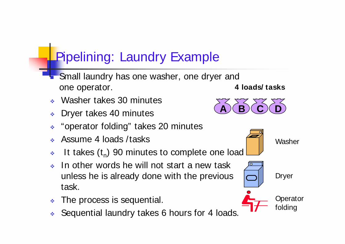
Pipelining: Laundry Example Small laundry has one washer, one dryer and
one operator. Washer takes 30 minutes Dryer takes 40 minutes “operator folding” takes 20 minutes Assume 4 loads /tasks It takes (tn) 90 minutes to complete one load In other words he will not start a new task
unless he is already done with the previoustask.
The process is sequential. Sequential laundry takes 6 hours for 4 loads.
A B C D
4 loads/tasks Small laundry has one washer, one dryer and
one operator. Washer takes 30 minutes Dryer takes 40 minutes “operator folding” takes 20 minutes Assume 4 loads /tasks It takes (tn) 90 minutes to complete one load In other words he will not start a new task
unless he is already done with the previoustask.
The process is sequential. Sequential laundry takes 6 hours for 4 loads.
Washer
Dryer
Operatorfolding

Sequential Laundry
A
B
30 40 20 30 40 20 30 40 20 30 40 20
6 PM 7 8 9 10 11 Midnight
Task
Order
Time
(tn)=90
A better idea would be start the next load washing while the first is drying. Then, while the first load was being folded, the second load would dry and a new
load could be put in the washer’
B
C
D
Task
Order
90 min
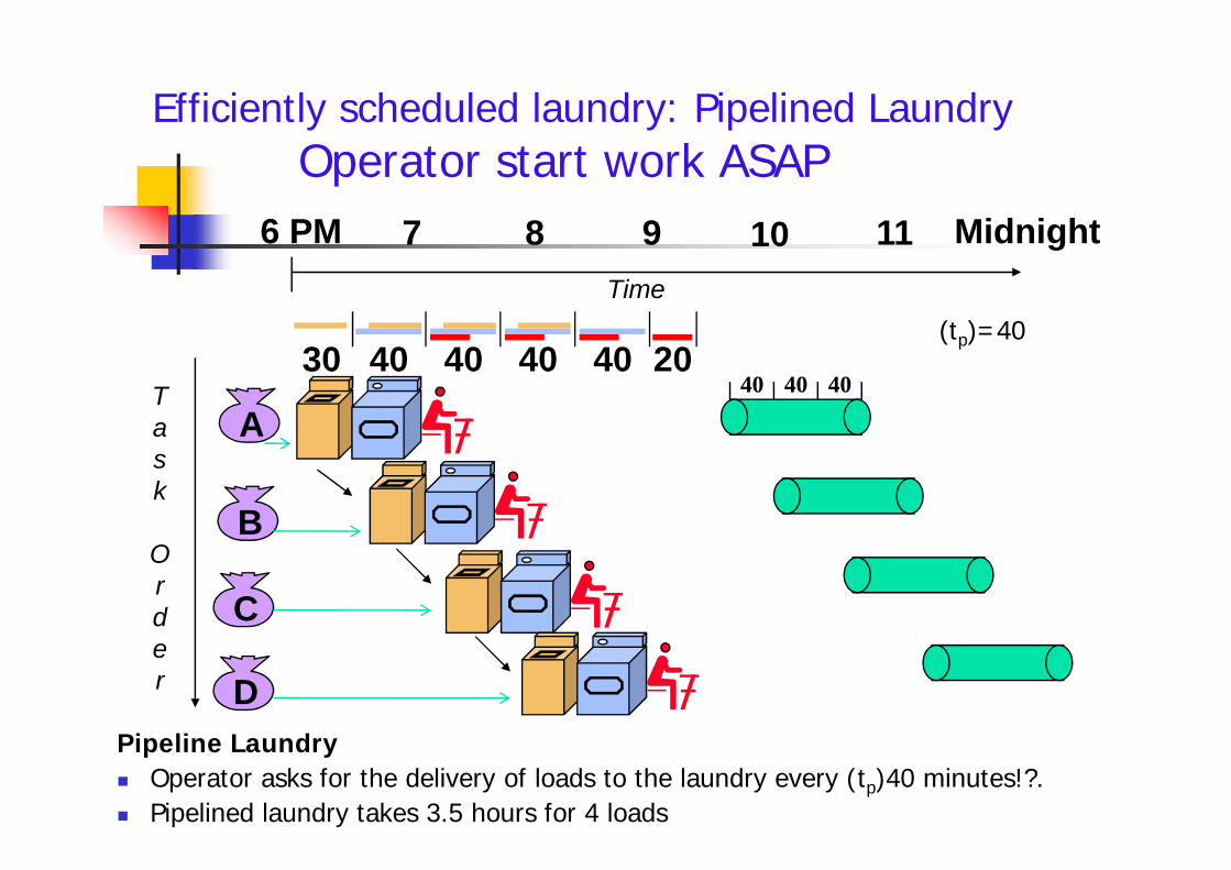
Efficiently scheduled laundry: Pipelined LaundryOperator start work ASAP
A
6 PM 7 8 9 10 11 Midnight
Task
Order
Time
30 40 40 40 40 2040 40 40
(tp)=40
Pipeline Laundry Operator asks for the delivery of loads to the laundry every (tp)40 minutes!?. Pipelined laundry takes 3.5 hours for 4 loads
A
B
C
D
Task
Order

Pipelining Lessons Multiple tasks operatingsimultaneously.
Pipelining doesn’t help latencyof single task, it helpsthroughput of entire workload.
Pipeline rate limited by slowestpipeline stage.
Potential speedup = Number ofpipe stages.
Unbalanced lengths of pipestages reduces speedup.
Time to “fill” pipeline and timeto “drain” it reduces speedup.
Pipelining improves performanceby increasing instructionthroughput, as opposed todecreasing the execution time ofany individual instruction.
A
6 PM 7 8 9
Task
Order
Time
30 40 40 40 40 20
Multiple tasks operatingsimultaneously.
Pipelining doesn’t help latencyof single task, it helpsthroughput of entire workload.
Pipeline rate limited by slowestpipeline stage.
Potential speedup = Number ofpipe stages.
Unbalanced lengths of pipestages reduces speedup.
Time to “fill” pipeline and timeto “drain” it reduces speedup.
Pipelining improves performanceby increasing instructionthroughput, as opposed todecreasing the execution time ofany individual instruction.
A
B
C
D
Task
Order
The washerwaits for thedryer for 10
minutes

The pipeline organization will be demonstratedby means of a simple example. To perform the combined multiply and add
operations with a stream of numbersAi * Bi + Ci for i = 1, 2, 3, …, 7
The pipeline organization will be demonstratedby means of a simple example. To perform the combined multiply and add
operations with a stream of numbersAi * Bi + Ci for i = 1, 2, 3, …, 7

Each suboperation is to be implemented in a segmentwithin a pipeline.
R1 Ai, R2 Bi Input Ai and Bi
R3 R1 * R2, R4 Ci Multiply and input Ci
R5 R3 + R4 Add Ci to product
Each segment has one or two registers and acombinational circuit as shown in Fig.2.
The five registers are loaded with new data every clockpulse. The effect of each clock is shown in Table 1.
Pipeline organization
Each suboperation is to be implemented in a segmentwithin a pipeline.
R1 Ai, R2 Bi Input Ai and Bi
R3 R1 * R2, R4 Ci Multiply and input Ci
R5 R3 + R4 Add Ci to product
Each segment has one or two registers and acombinational circuit as shown in Fig.2.
The five registers are loaded with new data every clockpulse. The effect of each clock is shown in Table 1.

Example of pipeline processing
Multiplier
R1 R2
Ai Bi Ci
R1 Ai ,R2 Bi Segment 1
Adder
Multiplier
R3 R4
R5
R3 R1 * R2, R4 Ci
R5 R3 + R4
Segment 2
Segment 3

Content of registers in pipeline example
ClockPulseNumber
Segment 1
R1 R2
Segment 2
R3 R4
Segment 3
R5
123456789
A1A2A3A4A5A6A7----
B1B2B3B4B5B6B7----
--A1*B1A2*B2A3*B3A4*B4A5*B5A6*B6A7*B7--
--C1C2C3C4C5C6C7--
----A1*B1+C1A2*B2+C2A3*B3+C3A4*B4+C4A5*B5+C5A6*B6+C6A7*B7+C7
123456789
A1A2A3A4A5A6A7----
B1B2B3B4B5B6B7----
--A1*B1A2*B2A3*B3A4*B4A5*B5A6*B6A7*B7--
--C1C2C3C4C5C6C7--
----A1*B1+C1A2*B2+C2A3*B3+C3A4*B4+C4A5*B5+C5A6*B6+C6A7*B7+C7

General considerations
Any operation that can be decomposed into a sequence ofsub-operations of about the same complexity can beimplemented by a pipeline processor.
The general structure of a four-segment pipeline isillustrated in Fig.3.
We define a task as the total operation performed goingthrough all the segments in the pipeline.
The behavior of a pipeline can be illustrated with a space-time diagram. It shows the segment utilization as a function of time.

Design of a basic pipeline
Pipeline has two ends, the input end and the output end.Between these ends, there are multiple stages/segmentssuch that output of one stage is connected to input of nextstage and each stage performs a specific operation.
Interface registers are used to hold the intermediateoutput between two stages. These interface registers arealso called latch or buffer.
All the stages in the pipeline along with the interfaceregisters are controlled by a common clock.

Clock
4-segment pipeline
Si Ristage/segment latch or buffer
ti Stage latency
R1 R2 R3 R4S1 S2 S3 S4Input
Fig.3
t1 td t2 td t3 td t4 td
what is the clock cycle time (tp)?
Latch delay : td ; tp= max {ti } + td ; Pipeline frequency : f = 1 / tp
output

The space-time diagrams for execution of 2instructions with :i) a four-segment pipelineii) a four-segment non-pipeline
are demonstrated in Fig.4 (a).
.
The space-time diagrams for execution of 2instructions with :i) a four-segment pipelineii) a four-segment non-pipeline
are demonstrated in Fig.4 (a).
.

Non-pipeline
pipeline
space-time diagramsFig.4

Problem
Cosider a k (4) -segment pipeline , with a clock cycle timetp , used to execute n (6) tasks.
-Draw the space-time diagram and observe:i) The utilization of the segments.ii) Time of execution of single task,two tasks and soiii) Efficiency of the pipeline
Cosider a k (4) -segment pipeline , with a clock cycle timetp , used to execute n (6) tasks.
-Draw the space-time diagram and observe:i) The utilization of the segments.ii) Time of execution of single task,two tasks and soiii) Efficiency of the pipeline

Space-time diagram for pipeline
1 2 3 4 5 6 7 8 9
1Segment:Clock cycles
task Ti
1
2
3
4
Segment:Clock cycles
T1 T2 T3 T4 T5 T6
T1 T2 T3 T4 T5 T6
T1 T2 T3 T4 T5 T6
T1 T2 T3 T4 T5 T6
Fig. space-time diagram Speedup ?Efficiency ?

Consider a k-segment pipeline ,with a clock cycle time tp , toexecute n tasks. The first task T1 requires a time equal to ktp to complete its operation. The remaining (n-1) tasks will be completed after a time equal to (n-
1)tp Therefore, to complete n tasks using a k-segment pipeline requires
k+(n-1) clock cycles.
Consider a non-pipeline unit that performs the sameoperation and takes a time equal to tn to complete each task. The total time required for n tasks is ntn.
Pipeline Speedup
Consider a k-segment pipeline ,with a clock cycle time tp , toexecute n tasks. The first task T1 requires a time equal to ktp to complete its operation. The remaining (n-1) tasks will be completed after a time equal to (n-
1)tp Therefore, to complete n tasks using a k-segment pipeline requires
k+(n-1) clock cycles.
Consider a non-pipeline unit that performs the sameoperation and takes a time equal to tn to complete each task. The total time required for n tasks is ntn.

Introduction(cont.) The speedup of a pipeline processing over an equivalent non-
pipeline processing is defined by the ratioSk = ntn /(k+n -1)tp
If n becomes much larger than (k-1), the speedup becomesSk ≈ tn / tp.
If we assume that the time it takes to process a task is thesame in the pipeline and non-pipeline circuits, i.e., tn = ktp,the speedup reduces to Sk=k tp /tp≈k.
This shows that the theoretical maximum speedup that apipeline can provide is k, where k is the number of segmentsin the pipeline.
The speedup of a pipeline processing over an equivalent non-pipeline processing is defined by the ratio
Sk = ntn /(k+n -1)tp If n becomes much larger than (k-1), the speedup becomes
Sk ≈ tn / tp. If we assume that the time it takes to process a task is the
same in the pipeline and non-pipeline circuits, i.e., tn = ktp,the speedup reduces to Sk=k tp /tp≈k.
This shows that the theoretical maximum speedup that apipeline can provide is k, where k is the number of segmentsin the pipeline.

Problem
The following numerical example may clarify the sub-operations performed in each segment (Fig.6)
The comparator, shift, adder-subtractor, incrementer, anddecrementer in the floating-point pipeline are implementedwith combinational circuits.
Suppose that the time delays of the four segments aret1=60ns, t2=70ns, t3=100ns, t4=80ns, and the interfaceregisters have a delay of tr=10ns Pipeline floating-point arithmetic delay: tp=t3+tr=110ns Non-pipeline floating-point arithmetic delay:
tn=t1+t2+t3+t4+tr=320ns Speedup: 320/110=2.9

To duplicate the theoretical speed advantage of a pipelineprocess by means of multiple functional units, it is necessaryto construct k identical units that will be operating in parallel.
This is illustrated in Fig.5, where four identical circuits areconnected in parallel.
Instead of operating with the input data in sequence as in apipeline, the parallel circuits accept four input data itemssimultaneously and perform four tasks at the same time.

Speed-upFor e.g., if a pipeline has 4 stages and 5 inputs
Speedup over an equivalent non-pipeline processing ?What is the maximum value of speedup ?
Sk = nk /(k+n -1)
The speedup value increases with increased number of tasks .
When the number of tasks ‘n’ are significantly larger than k,that is, n >> k
Lt [Speedup] = K , reaches max value of Skn ∞
For e.g., if a pipeline has 4 stages and 5 inputsSpeedup over an equivalent non-pipeline processing ?
What is the maximum value of speedup ?Sk = nk /(k+n -1)
The speedup value increases with increased number of tasks .
When the number of tasks ‘n’ are significantly larger than k,that is, n >> k
Lt [Speedup] = K , reaches max value of Skn ∞

Efficiency and ThroughputEfficiency and ThroughputEfficiency of the k-stages pipeline :
Efficiency= EkSk
k= n
k + (n-1)
Indicator of how efficiently the resources of the pipeline are used.
Efficiency = Given speed up / Max speed up = Sk / Sk(max)
Pipeline throughput (also called bandwidth)It is the measure of how often an instruction exits the pipeline.It is the average number of results computed in one cycle.Or the number of input tasks that can performed in one cycle time.
Hkn
[ k + (n-1)] = n fk + (n-1)
What is the maximum value of efficiency ? When …?What is the lowest value of efficiency? When …?
=
i.e Number of instructions / Total time to complete the instructionsWhat is the maximum value of Hk?
Efficiency = Given speed up / Max speed up = Sk / Sk(max)

Note
Ek, the speedup per stage, approaches its maximumvalue of 1 when n ∞ .
When n=1, Ek will have the value 1/k, which is thelowest obtainable value
When n ∞, the throughput Hk approaches themaximum value of one task per clock cycle.
Pipeline throughput = Efficiency * frequency
Ek, the speedup per stage, approaches its maximumvalue of 1 when n ∞ .
When n=1, Ek will have the value 1/k, which is thelowest obtainable value
When n ∞, the throughput Hk approaches themaximum value of one task per clock cycle.
Pipeline throughput = Efficiency * frequency

Latency, Efficiency and ThroughputPipeline latency Each instruction takes a certain time to complete. This is the latency for that operation. It's the amount of time between when the instruction is issued and when
it completes.Pipeline Throughput the rate at which operations get executed- generally expressed as operations/second or operations/cycle Need not be the same as dividing the time span by the latencyIn machines with no pipelining:
The machine cycle must be long enough to complete a single instructionThroughput = 1/latency , The latency is the same as cycle timeSince each operation executes by itself
If an instruction is divided into smaller chunks (multiple clock cyclesper instruction) then Throughput is not the same
Pipeline latency Each instruction takes a certain time to complete. This is the latency for that operation. It's the amount of time between when the instruction is issued and when
it completes.Pipeline Throughput the rate at which operations get executed- generally expressed as operations/second or operations/cycle Need not be the same as dividing the time span by the latency

Problem 1 Consider the execution of a program of 10/100/15000
instructions by a linear pipeline processor with a clock rate of25MHz. Assume that the instruction pipeline has 5 stages andthat one instruction is issued per clock cycle. The penalties dueto branch instructions and out-of-sequence executions areignored
a) Calculate the speedup factor as compared with non-pipelinedprocessor
b) What are the efficiency and throughput of this pipelinedprocessor?
Consider the execution of a program of 10/100/15000instructions by a linear pipeline processor with a clock rate of25MHz. Assume that the instruction pipeline has 5 stages andthat one instruction is issued per clock cycle. The penalties dueto branch instructions and out-of-sequence executions areignored
a) Calculate the speedup factor as compared with non-pipelinedprocessor
b) What are the efficiency and throughput of this pipelinedprocessor?

From the problem:n =10,100 and 15000f= 25MHzK=5 stages
III) Speedup Sk= (nk)/ (n+k-1)= (1500*5)/(1500+5-1)=75,000/1504= 4.999
Efficiency=Ek = Sk/k= 4.999/5= 0.999Throughput=Hk = 0.999*25 MHz= 24.99 MIPS
II)Sk=500/104=4.8076 ;Ek =4.8076/5 =0.9615 ; Hk=24.038 MIPS
I) Sk=50/14 =3.5714 ; Ek =3.5714 /5 =0.7143 ; Hk= 17.857MIPS

Fetch Decode Cal. operandaddress
Execute Saveresults
Pipeline 1 300 400 350 550 100
pipeline 2 200 150 100 190 140
Problem2.Consider 5 stages of the processors that have the following latencies (in p sec.)Assume that when pipelining, each pipeline stage costs 20ps extra for theregisters between pipeline stages.
1) For both Non-pipelined and pipelined processing , Compute :what is the cycle time? What is the latency of an instruction?What is the throughput?
2) If you could split one of the pipeline stages into 2 equal halves, whichone would you choose? What is the new cycle time? What is the newlatency? What is the new throughput?

1 (a) Non-pipelined processing;
Because there is no pipelining, the cycle time must allow aninstruction to go through all stages in one cycle.The latency is the same as cycle time since it takes theinstruction one cycle to go from the beginning of fetch to theend of writeback (save).The throughput is defined as 1/CT inst/s.
P 1 : CT = 300 + 400 + 350 + 550 + 100 = 1700psLatency = 1700psThroughput = 1/1700 inst/ps
P 2 : CT = 200 + 150 + 100 + 190 + 140 = 780psLatency = 780psThroughput = 1/780 inst/ps

1 (b) Pipelined processing:Pipelining reduces the cycle time to the length of the longeststage plus the register delay.Latency becomes CT*N where N is the number of stages asone instruction will need to go through each of the stagesand each stage takes one cycle.The throughput formula remains the same.P 1. CT = 550 + 20 = 570 ps
Latency = 5 * 570 = 2850psThroughput = 1/570 inst/ps
P 2. CT = 200 + 20 = 220 psLatency = 5 * 220 = 1100psThroughput = 1/220 inst/ps

2. If you could split one of the pipeline stages into 2 equal halves.
We would want to choose the longest stage to split into half.The new cycle time becomes the originally 2nd longest stagelength. Calculate latency and throughput correspondingly, butremember there are now 6 stages instead of 5.a. CT = 400 + 20 = 420 ps
Latency = 6 * 420 = 2520 psThroughput = 1/420 inst/ps
b. CT = 190 + 20 = 210 psLatency = 6 * 210 = 1260 psThroughput = 1/210 inst/ps

How the performance of apipeline be improved ?
How the performance of apipeline be improved ?

How to improve the performance of a pipeline?1. Make the clock rate faster.2. Duplicate functional units to allow parallel execution
of instructions.3. Increase the number of stages in the pipeline4. Allow all pipeline stages possibly take the same processtime.
Ideally, all stages should be exactly the same length.5. By avoiding data dependency/unconditional jumps

Multiple functional units in parallel
IiIi+1 Ii+2 Ii+3
P1 P2 P3 P4
Fig.5

There are various reasons why the pipeline cannot operateat its maximum theoretical rate. Different segments may take different times to complete their
suboperation. It is not always correct to assume that a nonpipe circuit has
the same time delay as that of an equivalent pipeline circuit. There are two areas of computer design where the pipeline
organization is applicable. Arithmetic pipeline Instruction pipeline

Arithmetic Pipeline

Arithmetic pipeline -Introduction Applications of arithmetic Pipeline units are usually found in
very high speed computers Floating–point operations, multiplication of fixed-point numbers, and
similar computations in scientific problem
Floating–point operations are easily decomposed into sub-operations as demonstrated in Sec.5.
Application of a pipeline unit for floating-point addition andsubtraction is showed in the following: The inputs to the floating-point adder pipeline are two normalized
floating-point binary number
Applications of arithmetic Pipeline units are usually found invery high speed computers Floating–point operations, multiplication of fixed-point numbers, and
similar computations in scientific problem
Floating–point operations are easily decomposed into sub-operations as demonstrated in Sec.5.
Application of a pipeline unit for floating-point addition andsubtraction is showed in the following: The inputs to the floating-point adder pipeline are two normalized
floating-point binary number
b
a
BY
AX
2
2
A and B are two fractions that represent the mantissasa and b are two integers that represent the the exponents

The floating-point addition and subtraction can be performed infour segments, as shown in Fig.6.
The suboperations that are performed in the four segments are: Compare the exponents
The larger exponent is chosen as the exponent of the result. Align the mantissas
The exponent difference determines how many times the mantissaassociated with the smaller exponent must be shifted to the right.
Perform the operation (Add or subtract the mantissas) Normalize the result
When an overflow occurs, the mantissa of the sum or difference isshifted right and the exponent incremented by one.
If an underflow occurs, the number of leading zeros in the mantissadetermines the number of left shifts in the mantissa and the number thatmust be subtracted from the exponent.
Floating-point addition The floating-point addition and subtraction can be performed in
four segments, as shown in Fig.6. The suboperations that are performed in the four segments are:
Compare the exponents The larger exponent is chosen as the exponent of the result.
Align the mantissas The exponent difference determines how many times the mantissa
associated with the smaller exponent must be shifted to the right. Perform the operation (Add or subtract the mantissas) Normalize the result
When an overflow occurs, the mantissa of the sum or difference isshifted right and the exponent incremented by one.
If an underflow occurs, the number of leading zeros in the mantissadetermines the number of left shifts in the mantissa and the number thatmust be subtracted from the exponent.

Floating Point Adder Unit
Our purpose is to compute the sumF = A + B = c x 10r = d x 10s
where A= a x 10p ; B= b x 10q
r = max (p,q) and 0.1 ≤ d < 1 For example:
A=0.9504 x 10³
B=0.8200 x 10²
a = 0.9504 b= 0.8200p=3 & q =2 ; r = 3
Our purpose is to compute the sumF = A + B = c x 10r = d x 10s
where A= a x 10p ; B= b x 10q
r = max (p,q) and 0.1 ≤ d < 1 For example:
A=0.9504 x 10³
B=0.8200 x 10²
a = 0.9504 b= 0.8200p=3 & q =2 ; r = 3

Floating Point Adder Unit
Operations performed in the four pipeline stages are :1. Compare the exponents
Compare p and q and choose the largest exponent,r = max (p,q) andcompute difference of exponents: t = |p – q|Example:r = max (p , q) = 3t = |p-q| = |3-2|= 1
Operations performed in the four pipeline stages are :1. Compare the exponents
Compare p and q and choose the largest exponent,r = max (p,q) andcompute difference of exponents: t = |p – q|Example:r = max (p , q) = 3t = |p-q| = |3-2|= 1

Floating Point Adder Unit
2. Align the mantissasRewrite the smaller number such that its exponentmatches with the exponent of the larger number.
Shift right the fraction associated with the smallerexponent by t units to equalize the two exponentsbefore fraction addition.
Example:Smaller exponent, b= 0.8200Shift right b by 1 (=t) unit is 0.082

Floating Point Adder Unit
3. Perform the operationPerform fixed-point addition of two fractions toproduce the intermediate sum fraction c
Example :a = 0.9504 ; b= 0.082c = a + b = 0.9504 + 0.082 = 1.0324
3. Perform the operationPerform fixed-point addition of two fractions toproduce the intermediate sum fraction c
Example :a = 0.9504 ; b= 0.082c = a + b = 0.9504 + 0.082 = 1.0324

Floating Point Adder Unit4. Normalize the result-(align radix point)
(shift mantissa and adjust exponent)Count the number of leading zeros (u) in fraction c andshift left c by u units to produce the normalized fractionsum d = c x 10u, with a leading bit 1.Update the large exponent s by subtracting s = (r – u) toproduce the output exponent.
Example:c = 1.0324 = 0.10324 x 10(3+1)
u = -1 right shiftd = 0.10324 , s= r – u = 3-(-1) = 4F = 0.10324 x 10⁴
4. Normalize the result-(align radix point)(shift mantissa and adjust exponent)
Count the number of leading zeros (u) in fraction c andshift left c by u units to produce the normalized fractionsum d = c x 10u, with a leading bit 1.Update the large exponent s by subtracting s = (r – u) toproduce the output exponent.
Example:c = 1.0324 = 0.10324 x 10(3+1)
u = -1 right shiftd = 0.10324 , s= r – u = 3-(-1) = 4F = 0.10324 x 10⁴

Floating Point Adder Unit
FP adder/subtractor is implemented by usingcombinational logic circuits in the following 4 stages:1. Comparator / Subtractor2. Shifter3. Fixed Point Adder-cum-subtractor4. Normalizer (leading zero counter and shifter)
FP adder/subtractor is implemented by usingcombinational logic circuits in the following 4 stages:1. Comparator / Subtractor2. Shifter3. Fixed Point Adder-cum-subtractor4. Normalizer (leading zero counter and shifter)

Pipeline for floating-point addition/subtraction
Segment 1:
R R
Compareexponents
by subtraction
t=1
Exponents Mantissasqp a b
For example:A=0.9504*103
B=0.8200*102
Segment 2:
Segment 3:
Segment 4:
R
R
R
R
R
R
Adjustexponent
Normalizeresult
Add or subtractmantissas
Align mantissas
Choose exponent
Compareexponents
by subtraction
For example:A=0.9504*103
B=0.8200*102
0.082
r=3
c=0.9504+0.082=1.0324
d=0.10324s=4

Instruction Pipeline

Instruction Pipeline
Pipeline processing can occur not only in the data streambut in the instruction as well.
Consider a computer with an instruction fetch unit and aninstruction execution unit designed to provide a two-segment pipeline.
Computers with complex instructions require other phasesin addition to above phases to process an instructioncompletely.

(FI) (EX)

6 segment Instruction pipeline1.Fetch the instruction from memory(FI)
Read next instruction into CPU2. Decode the instruction (DI)
Determine opcode and operand specifiers.3. Calculate the effective address (CA)
Calculate the effective addresses of all operands(on branch, calculate target address of branch)
4. Fetch the operands (FO)Fetch operands from memory or register file
5. Execute the instruction(EX)Perform the indicated operation
6. Store the result (SR)Write operand to memory or register file
Some instructions skip some phases* Effective address calculation can be done in the part of the decoding phase* Storage of the operation result into a register is done automatically in the execution phase

4 segment pipeline FI: segment 1 that fetches the instruction. DA: segment 2 that decodes the instruction and
calculates the effective address. FO: segment 3 that fetches the operands. EX: segment 4 that executes the instruction.
FI: segment 1 that fetches the instruction. DA: segment 2 that decodes the instruction and
calculates the effective address. FO: segment 3 that fetches the operands. EX: segment 4 that executes the instruction.

Draw the timing diagrams for:2 - stage instruction pipeline
3 - stage instruction pipeline6 - stage instruction pipeline
Draw the timing diagrams for:2 - stage instruction pipeline
3 - stage instruction pipeline6 - stage instruction pipeline

Limitations at glance
There are certain difficulties that will prevent theinstruction pipeline from operating at its maximum rate.
Different segments may take different times to operateon the incoming information.
Some segments are skipped for certain operations. Two or more segments may require memory access at
the same time, causing one segment to wait until anotheris finished with the memory

Example: four-segment instruction pipeline Assume that:
The decoding of the instruction can be combined with thecalculation of the effective address into one segment.
The instruction execution and storing of the result can becombined into one segment.
Fig.7 shows how the instruction cycle in the CPU can beprocessed with a four-segment pipeline. Thus up to four sub-operations in the instruction cycle can
overlap and up to four different instructions can be inprogress of being processed at the same time.
Assume that: The decoding of the instruction can be combined with the
calculation of the effective address into one segment. The instruction execution and storing of the result can be
combined into one segment. Fig.7 shows how the instruction cycle in the CPU can be
processed with a four-segment pipeline. Thus up to four sub-operations in the instruction cycle can
overlap and up to four different instructions can be inprogress of being processed at the same time.

Four-segment pipeline
Fetch instructionfrom memory
Decode instructionand calculate
effective address
Segment 1:
Segment 2:Decode instruction
and calculateeffective address
Branch
Fetch operandfrom memory
Execute instruction
Interrupt
Interrupthandling
Update PC
Empty pipe
Segment 2:
Segment 3:
Segment 4:
yes
yes
no
noFig .7

An instruction in the sequence may cause a branchout of normal sequence. In that case the pending operations in the last two segments
are completed and all information stored in theinstruction buffer is deleted.
Similarly, an interrupt request will cause the pipeline to emptyand start again from a new address value.
Fig.8 shows the operation (Timing of instruction pipeline )of the instruction pipeline.

Timing of instruction pipeline
1 2 3 4 5 6 7 8 9 10 11 12 13
1
2
FI DA FO EX
FI DA FO EXInstruction:
Step:
3
4
5
6
7
FI DA FO EX
FI DA FO EX
FI DA FO EX
FI DA FO EX
FI DA FO EX
FI ——
—— —
(Branch)
FI: the segment that fetches an instructionDA: the segment that decodes the instruction
and calculate the effective addressFO: the segment that fetches the operandEX: the segment that executes the instruction
Fig.8

Hazard: A condition that causes the pipeline to stall because of someconflict in the pipe.Hazards prevent the next instruction in pipe from executing in its turn.Stalls: The period in which any stages of a pipeline are idle.
They are also referred to as bubbles in the pipelineTypes of hazards
Structural Hazards : contention for same hardware resourceData Hazards : dependency on earlier instruction for the
correct sequencing of register reads and writesControl Hazards : branch/jump instructions stall the pipe
until get correct target address into PC
Pipelining Hazards
Hazard: A condition that causes the pipeline to stall because of someconflict in the pipe.Hazards prevent the next instruction in pipe from executing in its turn.Stalls: The period in which any stages of a pipeline are idle.
They are also referred to as bubbles in the pipelineTypes of hazards
Structural Hazards : contention for same hardware resourceData Hazards : dependency on earlier instruction for the
correct sequencing of register reads and writesControl Hazards : branch/jump instructions stall the pipe
until get correct target address into PC

Pipeline conflictsThree types of hazards are possible in pipeline systemsStructural hazards (Resource conflicts ) In a situation when two instructionsrequire the use of the same hardware resource at the same time.The most common case in which this hazard may arise is in access to memory.
Data Hazards (Data dependency conflicts )A condition in which either the source or the destination operands of aninstruction are not available at the time expected in the pipeline.As a result some operation has to be delayed, and the pipeline stalls.Control /Instruction Hazards (Branch/ Instruction interrupts/Cache miss)A pipeline be stalled because of a delay in the availability of an instructionArise from branch /jump and other instructions that change the value of PCThese instructions stall the pipe until they get correct target address into PC .
Three types of hazards are possible in pipeline systemsStructural hazards (Resource conflicts ) In a situation when two instructionsrequire the use of the same hardware resource at the same time.The most common case in which this hazard may arise is in access to memory.
Data Hazards (Data dependency conflicts )A condition in which either the source or the destination operands of aninstruction are not available at the time expected in the pipeline.As a result some operation has to be delayed, and the pipeline stalls.Control /Instruction Hazards (Branch/ Instruction interrupts/Cache miss)A pipeline be stalled because of a delay in the availability of an instructionArise from branch /jump and other instructions that change the value of PCThese instructions stall the pipe until they get correct target address into PC .

• Pipeline stall (insert bubble)• Have 2 memory ports for shared instruction-data
cache-memory (expensive)• Have separate instruction cache-memory and data
cache-memory
Structural Hazards-Solutions
• Pipeline stall (insert bubble)• Have 2 memory ports for shared instruction-data
cache-memory (expensive)• Have separate instruction cache-memory and data
cache-memory

A difficulty that may caused a degradation ofperformance in an instruction pipeline is due topossible collision of data or address. A data dependency occurs when an instruction needs data
that are not yet available. An address dependency may occur when an operand
address cannot be calculated because the informationneeded by the addressing mode is not available.
Pipelined computers deal with such conflictsbetween data dependencies in a variety of ways.
Three Generic Data Hazards: RAW,WAR and WOW
Structural Hazards-Solutions A difficulty that may caused a degradation of
performance in an instruction pipeline is due topossible collision of data or address. A data dependency occurs when an instruction needs data
that are not yet available. An address dependency may occur when an operand
address cannot be calculated because the informationneeded by the addressing mode is not available.
Pipelined computers deal with such conflictsbetween data dependencies in a variety of ways.
Three Generic Data Hazards: RAW,WAR and WOW

Data dependency solutions Hardware interlocks :Detect conflicts and delay the progression of an instruction throughthe pipeline until all necessary data is available.Ex. Delayed load is performed by the compiler, which inserts NOP (nooperation) instructions to ensure that data dependencies are satisfied withoutthe need for additional hardware
This approach maintains the program sequence by using hardware toinsert the required delays.
Operand forwarding : In simple words, if the operands of next instruction isdepending on the previous instruction result, after execution (EX) of previousinstruction, the result will be directly written (copied) to Register locationexpected in Next instruction. This method requires additional hardware paths through multiplexers as
well as the circuit that detects the conflict. Data Hazards Remedy (SW)-Delayed load : (Fig.9)
to delay the loading of the conflicting data by inserting NOP instructions.
Hardware interlocks :Detect conflicts and delay the progression of an instruction throughthe pipeline until all necessary data is available.Ex. Delayed load is performed by the compiler, which inserts NOP (nooperation) instructions to ensure that data dependencies are satisfied withoutthe need for additional hardware
This approach maintains the program sequence by using hardware toinsert the required delays.
Operand forwarding : In simple words, if the operands of next instruction isdepending on the previous instruction result, after execution (EX) of previousinstruction, the result will be directly written (copied) to Register locationexpected in Next instruction. This method requires additional hardware paths through multiplexers as
well as the circuit that detects the conflict. Data Hazards Remedy (SW)-Delayed load : (Fig.9)
to delay the loading of the conflicting data by inserting NOP instructions.

35
Data Hazards Remedy - SW
Software delay (compiler or machine code programming to insert NOPs)MOVA R1, R5
NOP
NOP
ADD R2, R1, R6
NOP
NOP
ADD R3, R1, R2
MOVA R1 , R5ADD R2, R1, R6ADD R2, R1, R6
18
36
Data Hazards Remedy - HW Hardware stalls
Hardware Data Forwarding• Add an extra path connecting ALU outputs to ALU inputs on the next clock
IF DR E DF W
IF DR E DF W
IF DR E DF W
IF DR
IF
MOVA R1, R52, 1,ADD R2 R1 R6
IF DR E DF W2, 1,ADD R2 R1 R6
Hazard detection
Fig.9

Re gisterfile
SRC1 SRC2
RSL T
Destination
Source 1
Source 2
(a) Datapath
ALU
E: Ex ecute(ALU)
W : Write(Re gister file)
SRC1,SRC2 RSL T
(b) P osition of the source and result registers in the processor pipeline
Figure 8.7. Operand forw arding in a pipelined processor .
F orw arding path
Re gisterfile
SRC1 SRC2
RSL T
Destination
Source 1
Source 2
(a) Datapath
ALU
E: Ex ecute(ALU)
W : Write(Re gister file)
SRC1,SRC2 RSL T
(b) P osition of the source and result registers in the processor pipeline
Figure 8.7. Operand forw arding in a pipelined processor .
F orw arding path
Fig.9 (a)

Handling of branch instructions
One of the major problems in operating an instructionpipeline is the occurrence of branch instructions. An unconditional branch always alters the sequential program
flow by loading the program counter with the target address. In a conditional branch, the control selects the target
instruction if the condition is satisfied or the next sequentialinstruction if the condition is not satisfied.
Pipelined computers employ following hardwaretechniques to minimize the performance degradationcaused by instruction branching.
1) Prefetch target instruction 2) Branch target buffer (BTB)3) Loop buffer 4) Branch prediction5) Delayed branch

Handling of branch instructions (cont.)
1) Prefetch target instruction: To prefetch the target instruction in addition to the instruction
following the branch. Both are saved until the branch is executed. Cache prefetching is a technique used by computer processors to
boost execution performance by fetching instructions or data fromtheir original storage in slower memory to a faster local memorybefore it is actually needed (hence the term 'prefetch'). (Fig.10)

Instruction Queue and Prefetching
F : Fetchinstruction
Instruction queueInstruction fetch unit
E:Executeinstruction
W : Writeresults
D :Decode
Fig.10 Use of an instruction queue in the hardware organization
unit

2) Branch target buffer (BTB): The BTB is an associative memory included in the fetch segment of
the pipeline. Each entry in the BTB consists of the address of a previously
executed branch instruction and the target instruction for thatbranch.
It also stores the next few instructions after the branch targetinstruction.
Handling of branch instructions2) Branch target buffer (BTB): The BTB is an associative memory included in the fetch segment of
the pipeline. Each entry in the BTB consists of the address of a previously
executed branch instruction and the target instruction for thatbranch.
It also stores the next few instructions after the branch targetinstruction.
Have two pipelinesWhen a conditional branch is recognized, the target of the branchis prefetced, in addition to the instruction following the branch• Prefetch each branch into a separate pipeline• Use appropriate pipeline

3) Loop buffer: Maintained by fetch stage of pipeline This is a small very high speed register file . Contains the most recently fetched instructions, in sequence. If a branch is to be taken, the hardware first cheeks whether the
branch target is within the buffer. If so, the next instruction is fetchedfrom the buffer
Very good for small loops or iterations If the loop buffer is large enough to contain all the instructions in a
loop, then those instructions need to be fetched from memory onlyonce, for the first iteration. For subsequent iterations, all the neededinstructions are already in the buffer.
Handling of branch instructions3) Loop buffer: Maintained by fetch stage of pipeline This is a small very high speed register file . Contains the most recently fetched instructions, in sequence. If a branch is to be taken, the hardware first cheeks whether the
branch target is within the buffer. If so, the next instruction is fetchedfrom the buffer
Very good for small loops or iterations If the loop buffer is large enough to contain all the instructions in a
loop, then those instructions need to be fetched from memory onlyonce, for the first iteration. For subsequent iterations, all the neededinstructions are already in the buffer.

4) Branch prediction A pipeline with branch prediction uses some additional logic to guess
the outcome of a conditional branch instruction before it is executed. Reducing the branch penalty requires the branch address to be
computed earlier in the pipeline Typically the Fetch unit has dedicated h/w which will identify the
branch target address as quick as possible after an instruction isfetched
Various techniques can be used to predict whether a branch will betaken or not (Fig.11). The most common techniques are:• Static Techniques• Dynamic Techniques
Handling of branch instructions4) Branch prediction A pipeline with branch prediction uses some additional logic to guess
the outcome of a conditional branch instruction before it is executed. Reducing the branch penalty requires the branch address to be
computed earlier in the pipeline Typically the Fetch unit has dedicated h/w which will identify the
branch target address as quick as possible after an instruction isfetched
Various techniques can be used to predict whether a branch will betaken or not (Fig.11). The most common techniques are:• Static Techniques• Dynamic Techniques

Static Techniques:a) Predict never taken - continue to fetch sequentially. If the branch isnot taken, then there is no wasted fetches.b) Predict always taken - fetch from branch target as soon as possiblec) Predict by opcode - compiler helps by having different opcodes basedon likely outcome of the branchDynamic Techniquestry to improve prediction by recording history of conditional branchd) Taken / Not Taken switch - one or more history bits to reflectwhether the most recent executions of an instruction were taken or not.e) Branch-History Table - small, fully-associative cache to storeinformation about most recently executed branch instructions.
Static Techniques:a) Predict never taken - continue to fetch sequentially. If the branch isnot taken, then there is no wasted fetches.b) Predict always taken - fetch from branch target as soon as possiblec) Predict by opcode - compiler helps by having different opcodes basedon likely outcome of the branchDynamic Techniquestry to improve prediction by recording history of conditional branchd) Taken / Not Taken switch - one or more history bits to reflectwhether the most recent executions of an instruction were taken or not.e) Branch-History Table - small, fully-associative cache to storeinformation about most recently executed branch instructions.

Branch early prediction
X
Figure 8.9. Branch timing.
F 1 D 1 E 1 W 1
I 2 (Branch)
I 1
1 2 3 4 5 6 7Clock c ycle
F 2 D 2
F 3 X
F k D k E k
F k+ 1 D k+ 1
I 3
I k
I k+ 1
W k
E k+ 1
(b) Branch address computed in Decode stage
F 1 D 1 E 1 W 1
I 2 (Branch)
I 1
1 2 3 4 5 6 7Clock c ycle
F 2 D 2
F 3
F k D k E k
F k+ 1 D k+ 1
I 3
I k
I k+ 1
W k
E k+ 1
(a) Branch address computed in Ex ecute stage
E 2
D 3
F 4 XI 4
8T ime
T ime
- Branch penalty
- Reducing the penaltyX
Figure 8.9. Branch timing.
F 1 D 1 E 1 W 1
I 2 (Branch)
I 1
1 2 3 4 5 6 7Clock c ycle
F 2 D 2
F 3 X
F k D k E k
F k+ 1 D k+ 1
I 3
I k
I k+ 1
W k
E k+ 1
(b) Branch address computed in Decode stage
F 1 D 1 E 1 W 1
I 2 (Branch)
I 1
1 2 3 4 5 6 7Clock c ycle
F 2 D 2
F 3
F k D k E k
F k+ 1 D k+ 1
I 3
I k
I k+ 1
W k
E k+ 1
(a) Branch address computed in Ex ecute stage
E 2
D 3
F 4 XI 4
8T ime
T ime
Fig.11
Fig.11
Fig.11

Handling of branch instructions
5) Delayed branch:The compiler detects the branch instructions and rearranges themachine language code sequence by inserting useful instructions thatkeep the pipeline operating without interruptions. A procedure employed in most RISC processors. e.g. no-operation instruction
5) Delayed branch:The compiler detects the branch instructions and rearranges themachine language code sequence by inserting useful instructions thatkeep the pipeline operating without interruptions. A procedure employed in most RISC processors. e.g. no-operation instruction
RISC and CISC
CISC : Complex Instruction Set ComputerRISC : Reduced Instruction Set Computer

CISCCISC instructions sets some common characteristics:
A 2-operand format, where instructions have a source and adestination. Register to register, register to memory, andmemory to register commands. Multiple addressing modes formemory, including specialized modes for indexing througharrays
Variable length instructions where the length often variesaccording to the addressing mode
Instructions which require multiple clock cycles to execute. Easy to program. Makes efficient use of memory
CISC instructions sets some common characteristics: A 2-operand format, where instructions have a source and a
destination. Register to register, register to memory, andmemory to register commands. Multiple addressing modes formemory, including specialized modes for indexing througharrays
Variable length instructions where the length often variesaccording to the addressing mode
Instructions which require multiple clock cycles to execute. Easy to program. Makes efficient use of memory

Characteristics of CISC
A large of instructions typically from 100 to 250 instructions. A large variety of addressing modes typically from 5 to 200
different modes. Complex and efficient machine instructions. Variable-length instruction formats. Instructions that manipulate operands in memory. Extensive addressing capabilities for memory operations. Relatively few registers.

CISC Disadvantages
Instruction set & chip hardware become more complex with eachgeneration of computers.
Many instructions as possible could be stored in memory withthe least possible wasted space, individual instructions could beof almost any length - this means that different instructions willtake different amounts of clock time to execute, slowing downthe overall performance of the machine.

What is RISC ?RISC architecture utilizes a small, highly-optimized set ofinstructions instead of specialized set of instructions oftenfound CISC.
Characteristic of most RISC processors: one cycle execution time: RISC processors have a CPI (clock
per instruction) of one cycle. This is due to the optimizationof each instruction on the CPU and a technique calledPIPELINING
pipelining: a techique that allows for simultaneous executionof parts, or stages, of instructions to more efficiently processinstructions;
large number of registers: the RISC design philosophygenerally incorporates a larger number of registers toprevent in large amounts of interactions with memory
Fixed-length, easily decoded instructions Intelligent compiler
RISC architecture utilizes a small, highly-optimized set ofinstructions instead of specialized set of instructions oftenfound CISC.
Characteristic of most RISC processors: one cycle execution time: RISC processors have a CPI (clock
per instruction) of one cycle. This is due to the optimizationof each instruction on the CPU and a technique calledPIPELINING
pipelining: a techique that allows for simultaneous executionof parts, or stages, of instructions to more efficiently processinstructions;
large number of registers: the RISC design philosophygenerally incorporates a larger number of registers toprevent in large amounts of interactions with memory
Fixed-length, easily decoded instructions Intelligent compiler

RISC Characteristics Reduced instruction set. Relatively few instructions. Relatively few addressing modes. Less complex, simple instructions. All operations done within the registers of the CPU. Small number of suboperations, with each being executed in
one clock cycle Efficient Instruction pipeline Uses simple decoder Hardwired control unit and machine instructions. Few addressing schemes for memory operands with only two
basic instructions, LOAD and STORE Memory access limited to LOAD and STORE instructions
Reduced instruction set. Relatively few instructions. Relatively few addressing modes. Less complex, simple instructions. All operations done within the registers of the CPU. Small number of suboperations, with each being executed in
one clock cycle Efficient Instruction pipeline Uses simple decoder Hardwired control unit and machine instructions. Few addressing schemes for memory operands with only two
basic instructions, LOAD and STORE Memory access limited to LOAD and STORE instructions

RISC Pipeline

Characteristics of RISC To use an efficient instruction pipeline
Suboperations to be executed in one clock cycle. Use of fixed-length instruction format to make decoding time
same as the register selection. RISC instruction pipeline can be implemented with 2 and 3
segments. One segment fetches the instruction from program
memory The other segment executes the instruction in the ALU Third segment may be used to store the result of the ALU
operation in a destination register
To use an efficient instruction pipeline Suboperations to be executed in one clock cycle. Use of fixed-length instruction format to make decoding time
same as the register selection. RISC instruction pipeline can be implemented with 2 and 3
segments. One segment fetches the instruction from program
memory The other segment executes the instruction in the ALU Third segment may be used to store the result of the ALU
operation in a destination register

Characteristics of RISC (cont.) The data transfer instructions in RISC are limited to load and store
instructions. These instructions use register indirect addressing. They usually
need three or four stages in the pipeline. To prevent conflicts between a memory access to fetch an
instruction and to load or store an operand, most RISCmachines use two separate buses with two memories.
Cache memory: operate at the same speed as the CPU clock Ability to execute instructions at the rate of one per clock cycle.
In effect, it is to start each instruction with each clock cycle andto pipeline the processor to achieve the goal of single-cycleinstruction execution.
RISC can achieve pipeline segments, requiring just one clockcycle.
The data transfer instructions in RISC are limited to load and storeinstructions. These instructions use register indirect addressing. They usually
need three or four stages in the pipeline. To prevent conflicts between a memory access to fetch an
instruction and to load or store an operand, most RISCmachines use two separate buses with two memories.
Cache memory: operate at the same speed as the CPU clock Ability to execute instructions at the rate of one per clock cycle.
In effect, it is to start each instruction with each clock cycle andto pipeline the processor to achieve the goal of single-cycleinstruction execution.
RISC can achieve pipeline segments, requiring just one clockcycle.

Characteristics of RISC (cont.)RISC processors rely on the efficiency of the compiler to
detect and minimize the delays encountered with theseproblems / difficulties associated with data conflicts andbranch penalties.
RISC processors rely on the efficiency of the compiler todetect and minimize the delays encountered with theseproblems / difficulties associated with data conflicts andbranch penalties.

3 Segment Instruction RISC Pipeline
Thee are three types of instructions: The data manipulation instructions: operate on data
in processor registers The data transfer instructions: The program control instructions:
Thee are three types of instructions: The data manipulation instructions: operate on data
in processor registers The data transfer instructions: The program control instructions:

Hardware operation The control section fetches the instruction from program
memory into an instruction register. The instruction is decoded at the same time that the
registers needed for the execution of the instruction areselected.
The processor unit consists of a number of registers and anarithmetic logic unit (ALU).
A data memory is used to load or store the data from aselected register in the register file.
The instruction cycle can be divided into three suboperations and implemented in three segments
The control section fetches the instruction from programmemory into an instruction register. The instruction is decoded at the same time that the
registers needed for the execution of the instruction areselected.
The processor unit consists of a number of registers and anarithmetic logic unit (ALU).
A data memory is used to load or store the data from aselected register in the register file.
The instruction cycle can be divided into three suboperations and implemented in three segments

RISC pipeline organization I: Instruction fetch
Fetches the instruction from program memory
A: ALU operation The instruction is decoded and an ALU operation is performed. It performs an operation for a data manipulation instruction. It evaluates the effective address for a load or store instruction. It calculates the branch address for a program control instruction.
E: Execute instruction Directs the output of the ALU to one of three destinations, depending on
the decoded instruction. It transfers the result of the ALU operation into a destination register in
the register file. It transfers the effective address to a data memory for loading or storing. It transfers the branch address to the program counter.
I: Instruction fetch Fetches the instruction from program memory
A: ALU operation The instruction is decoded and an ALU operation is performed. It performs an operation for a data manipulation instruction. It evaluates the effective address for a load or store instruction. It calculates the branch address for a program control instruction.
E: Execute instruction Directs the output of the ALU to one of three destinations, depending on
the decoded instruction. It transfers the result of the ALU operation into a destination register in
the register file. It transfers the effective address to a data memory for loading or storing. It transfers the branch address to the program counter.

RISC Pipelining Basics1. ALU operation with register input and output
two phases of execution for register based instructions I: Instruction fetch E: Execute
2. Register to memory or memory to register operationFor load and store there will be three phases I: Instruction fetch E: Execute
Calculate memory address D: Memory
1. ALU operation with register input and outputtwo phases of execution for register based instructions
I: Instruction fetch E: Execute
2. Register to memory or memory to register operationFor load and store there will be three phases I: Instruction fetch E: Execute
Calculate memory address D: Memory

1. Data Manipulation InstructionsI: Instruction FetchA: Decode, Read Registers, ALU OperationsE: Write a Register
2. Load and Store InstructionsI: Instruction FetchA: Decode, Evaluate Effective AddressE: Register-to-Memory or Memory-to-Register
3. Program Control InstructionsI: Instruction FetchA: Decode, Evaluate Branch AddressE: Write Register(PC)
RISC -Three-Stage Instruction Pipeline1. Data Manipulation Instructions
I: Instruction FetchA: Decode, Read Registers, ALU OperationsE: Write a Register
2. Load and Store InstructionsI: Instruction FetchA: Decode, Evaluate Effective AddressE: Register-to-Memory or Memory-to-Register
3. Program Control InstructionsI: Instruction FetchA: Decode, Evaluate Branch AddressE: Write Register(PC)

Optimization of RISC Pipelining
Delayed branch Leverages branch that does not take effect until
after execution of following instruction

Delayed Load Consider the operation of the following four instructions:
There will be a data conflict in instruction 3 because theoperand in R2 is not yet available in the A segment.
This can be seen from the timing of the pipeline shown in Fig.12(a). The E segment in clock cycle 4 is in a process of placing the
memory data into R2. The A segment in clock cycle 4 is using the data from R2.
compiler has to make sure that the instruction following theload instruction uses the data fetched from memory.
1. LOAD: R1 M[address 1]2. LOAD: R2 M[address 2]3. ADD: R3 R1 +R24. STORE: M[address 3] R3
Consider the operation of the following four instructions:
There will be a data conflict in instruction 3 because theoperand in R2 is not yet available in the A segment.
This can be seen from the timing of the pipeline shown in Fig.12(a). The E segment in clock cycle 4 is in a process of placing the
memory data into R2. The A segment in clock cycle 4 is using the data from R2.
compiler has to make sure that the instruction following theload instruction uses the data fetched from memory.

Delayed Load(cont.)
This concept of delaying the use of the data loaded frommemory is referred to as delayed load.
Fig. 12(b) shows the same program with a no-op instructioninserted after the load to R2 instruction.
Thus the no-op instruction is used to advance one clockcycle in order to compensate for the data conflict in thepipeline.
The advantage of the delayed load approach is that thedata dependency is taken care of by the compiler ratherthan the hardware.

3-segment pipeline time-space diagram1 2 3 4 5 6Clock cycles:
1. Load R1
2. Load R2
3. Add R1+R2
4. Store R3
I A E
I A E
I A E
I A ELOAD: R1 M[address 1]LOAD: R2 M[address 2]ADD: R3 R1 +R2STORE: M[address 3] R3 1 2 3 4 5 6 7
4. Store R3
1. Load R1
2. Load R2
3. No-operation
4. Add R1+R2
5. Store R3
I A E
I A E
I A E
I A E
I A E
I A E
12(a) Pipeline timing with data conflict
12 (b) Pipeline timing with delayed load
LOAD: R1 M[address 1]LOAD: R2 M[address 2]ADD: R3 R1 +R2STORE: M[address 3] R3

Delayed Branch
The method used in most RISC processors is to rely on thecompiler to redefine the branches so that they take effect atthe proper time in the pipeline. This method is referred to asdelayed branch.
The compiler is designed to analyze the instructions before andafter the branch and rearrange the program sequence byinserting useful instructions in the delay steps.
It is up to the compiler to find useful instructions to put afterthe branch instruction. Failing that, the compiler can insert no-op instructions.

An Example of Delayed Branch Ex.The program of delayed branch:
In Fig.13(a) the compiler inserts two no-op instructionsafter the branch. The branch address X is transferred to PC in clock cycle
7. The program in Fig.13(b) is rearranged by placing the add
and subtract instructions after the branch instruction. PC is updated to the value of X in clock cycle 5.
Load from memory to R1Increment R2Add R3 to R4Subtract R5 from R6Branch to address X
Ex.The program of delayed branch:
In Fig.13(a) the compiler inserts two no-op instructionsafter the branch. The branch address X is transferred to PC in clock cycle
7. The program in Fig.13(b) is rearranged by placing the add
and subtract instructions after the branch instruction. PC is updated to the value of X in clock cycle 5.
Load from memory to R1Increment R2Add R3 to R4Subtract R5 from R6Branch to address X

Example:delayed branch
1 2 3 4 5 6 7
1. Load
2. Increment
I A E
I A E
8 9 10Clock cycles:
Load from memory to R1Increment R2Add R3 to R4Subtract R5 from R6Branch to address X
2. Increment
3. Add
4. Subtract
5. Branch to X
I A E
I A E
I A E
I A E
6. No-operation
8. Instruction in X
7. No-operation
I A E
I A E
I A E
13 (a) Using no-operation instructions

Example:delayed branch(cont.)
1 2 3 4 5 6 7
1. Load
2. Increment
I A E
I A E
8Clock cycles:
Load from memory to R1Increment R2Add R3 to R4Subtract R5 from R6Branch to address X
2. Increment
3. Branch to X
4. Add
5. Subtract
I A E
I A E
I A E
I A E
6. Instruction in X I A E
13 (b) Rearranging the instructions
Compiler analyzes the instructions before and after the branch andrearranges the program sequence by inserting useful instructions in thedelay steps

Vector Processing
Introduction
In many science and engineering applications, the problems canbe formulated in terms of vectors and matrices that lendthemselves to vector processing.
Computers with vector processing capabilities are in demand inspecialized applications. e.g. Long-range weather forecasting Petroleum explorations Seismic data analysis Medical diagnosis Artificial intelligence and expert systems Image processing Mapping the human genome

Introduction(cont.)
To achieve the required level of high performance it isnecessary to utilize the fastest and most reliable hardware apply innovative procedures
(vector and parallel processing techniques)
To achieve the required level of high performance it isnecessary to utilize the fastest and most reliable hardware apply innovative procedures
(vector and parallel processing techniques)

Vector Operations Many scientific problems require arithmetic operations on large
arrays of numbers. A vector is an ordered set of a 1-D array of data items. A vector V of length n is represented as a row vector by
V=[v1,v2,…,vn]. To examine the difference between a conventional scalar
processor and a vector processor, consider the followingFortran DO loop:
DO 20 I = 1, 10020 C(I) = B(I) + A(I)
Many scientific problems require arithmetic operations on largearrays of numbers.
A vector is an ordered set of a 1-D array of data items. A vector V of length n is represented as a row vector by
V=[v1,v2,…,vn]. To examine the difference between a conventional scalar
processor and a vector processor, consider the followingFortran DO loop:
DO 20 I = 1, 10020 C(I) = B(I) + A(I)

Vector Operations(cont.)
This is implemented in machine language by thefollowing sequence of operations.
A computer capable of vector processing eliminatesthe overhead associated with the time it takes to fetchand execute the instructions in the program loop.
C(1:100) = A(1:100) + B(1:100)
Initialize I=020 Read A(I)
Read B(I)Store C(I) = A(I)+B(I)Increment I = I + 1If I 100 go to 20Continue

Vector Operations (cont.)
A possible instruction format for a vector instruction isshown in Fig.14. This assumes that the vector operands reside in memory.
It is also possible to design the processor with a largenumber of registers and store all operands in registersprior to the addition operation. The base address and length in the vector instruction specify
a group of CPU registers.

Vector Processor
Operationcode
Base addresssource 1
Base addresssource 2
Base addressdestination
Vectorlength
Instruction format
Operationcode
Base addresssource 1
Base addresssource 2
Base addressdestination
Vectorlength
Fig.14.

Matrix Multiplication The multiplication of two n x n matrices consists of n2
inner products or n3 multiply-add operations. Consider, for example, the multiplication of two 3 x 3 matrices A and B.
C =A * B and C= C11 + C22 + C33
c11= a11b11+ a12b21+ a13b31 : C22= a21b12+ a22b22+ a23b32
C22= a21b12+ a22b22+ a23b32
This requires 3 multiplication and (after initializing c11 to 0) 3 additions.
In general, the inner product consists of the sum of kproduct terms of the form C =A1B1+A2B2+A3B3+…+AkBk. In a typical application k may be equal to 100 or even 1000.
The inner product calculation on a pipeline vectorprocessor is shown in Fig.12.
The multiplication of two n x n matrices consists of n2
inner products or n3 multiply-add operations. Consider, for example, the multiplication of two 3 x 3 matrices A and B.
C =A * B and C= C11 + C22 + C33
c11= a11b11+ a12b21+ a13b31 : C22= a21b12+ a22b22+ a23b32
C22= a21b12+ a22b22+ a23b32
This requires 3 multiplication and (after initializing c11 to 0) 3 additions.
In general, the inner product consists of the sum of kproduct terms of the form C =A1B1+A2B2+A3B3+…+AkBk. In a typical application k may be equal to 100 or even 1000.
The inner product calculation on a pipeline vectorprocessor is shown in Fig.12.
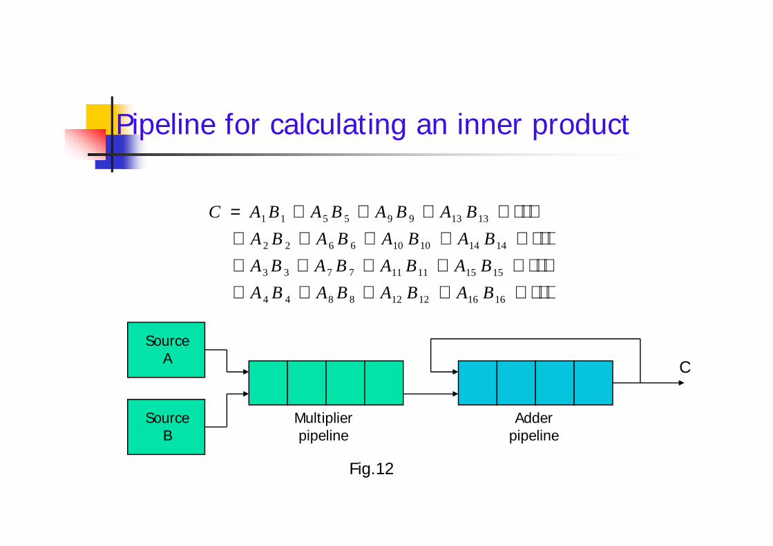
Pipeline for calculating an inner product
161612128844
151511117733
141410106622
1313995511
BABABABA
BABABABA
BABABABA
BABABABAC
SourceA
SourceB
Multiplierpipeline
Adderpipeline
161612128844
151511117733
141410106622
1313995511
BABABABA
BABABABA
BABABABA
BABABABAC
Fig.12
C

Pipeline for calculating an inner product
161612128844
151511117733
141410106622
1313995511
BABABABA
BABABABA
BABABABA
BABABABAC
Product pi=AiBi
SourceA
SourceB
Multiplierpipeline
Adderpipeline
161612128844
151511117733
141410106622
1313995511
BABABABA
BABABABA
BABABABA
BABABABAC
Fig.12 (a)-After 4 units of time
Cp4p3p2p1

Pipeline for calculating an inner product
161612128844
151511117733
141410106622
1313995511
BABABABA
BABABABA
BABABABA
BABABABAC
Product pi=AiBi
SourceA
SourceB
Multiplierpipeline
Adderpipeline
161612128844
151511117733
141410106622
1313995511
BABABABA
BABABABA
BABABABA
BABABABAC
Fig.12 (a)-After 8 units of time
Cp4p3p2p1

Pipeline for calculating an inner product
161612128844
151511117733
141410106622
1313995511
BABABABA
BABABABA
BABABABA
BABABABAC
Product pi=AiBi
SourceA
SourceB
Multiplierpipeline
Adderpipeline
161612128844
151511117733
141410106622
1313995511
BABABABA
BABABABA
BABABABA
BABABABAC
Fig.12 (a)-After 4 units of time
Cp4p3p2p1

Pipeline for calculating an inner product
161612128844
151511117733
141410106622
1313995511
BABABABA
BABABABA
BABABABA
BABABABAC
Product pi=AiBi
p4 p3 p2 p1
SourceA
SourceB
Multiplierpipeline
Adderpipeline
161612128844
151511117733
141410106622
1313995511
BABABABA
BABABABA
BABABABA
BABABABAC
Fig.12 (a)-After 8 units of time
Cp5p6p7p8

Pipeline for calculating an inner product
161612128844
151511117733
141410106622
1313995511
BABABABA
BABABABA
BABABABA
BABABABAC
Product pi=AiBi
C= p1+p5 +p9+p13+ p2+p6 +p10+p14+ p3+p7 +p11+p15+ p4+p8 +p12+p16
p4 p3 p2 p1
SourceA
SourceB
Multiplierpipeline
Adderpipeline
161612128844
151511117733
141410106622
1313995511
BABABABA
BABABABA
BABABABA
BABABABAC
Fig.12 (a)-After 9 units of time C=p1
p5p6p7p8
and so on
+p5
C= p1+p5 +p9+p13+ p2+p6 +p10+p14+ p3+p7 +p11+p15+ p4+p8 +p12+p16

Memory Interleaving Pipeline and vector processors often require simultaneous
access to memory from two or more sources. An instruction pipeline may require the fetching of an instruction and an
operand at the same time from two different segments. An arithmetic pipeline usually requires two or more operands to enter the
pipeline at the same time. Instead of using two memory buses for simultaneous access, the
memory can be partitioned into a number of modules connected toa common memory address and data buses.
The advantage of a modular memory is that it allows the use of atechnique called interleaving. A memory module is a memory array together with its own address and
data registers. Fig.13 shows a memory unit with four modules.
Pipeline and vector processors often require simultaneousaccess to memory from two or more sources. An instruction pipeline may require the fetching of an instruction and an
operand at the same time from two different segments. An arithmetic pipeline usually requires two or more operands to enter the
pipeline at the same time. Instead of using two memory buses for simultaneous access, the
memory can be partitioned into a number of modules connected toa common memory address and data buses.
The advantage of a modular memory is that it allows the use of atechnique called interleaving. A memory module is a memory array together with its own address and
data registers. Fig.13 shows a memory unit with four modules.

Memory Organization-Multiple modules
AR AR AR AR
Address bus
AR
DR
Memoryarray
AR
DR
Memoryarray
AR
DR
Memoryarray
AR
DR
Memoryarray
Data busFig.13

Memory Interleaving(cont.) Memory interleaving is the technique used to increase the
throughput. The core idea is to split the memory system into independent banks,
which can answer read or write requests independently in parallel. In an interleaved memory, different sets of addresses are assigned to
different memory modules. By staggering the memory access, the effective memory cycle time
can be reduced by a factor close to the number of modules. The ultimate purpose is to match the memory bandwidth with the bus
bandwidth and with the processor bandwidth. There are two-address format for memory interleaving the
address space.Low order interleaving and High order interleaving
.
Memory interleaving is the technique used to increase thethroughput.
The core idea is to split the memory system into independent banks,which can answer read or write requests independently in parallel.
In an interleaved memory, different sets of addresses are assigned todifferent memory modules.
By staggering the memory access, the effective memory cycle timecan be reduced by a factor close to the number of modules.
The ultimate purpose is to match the memory bandwidth with the busbandwidth and with the processor bandwidth.
There are two-address format for memory interleaving theaddress space.
Low order interleaving and High order interleaving
.

Lower order interleaving (LOI) LOI spreads contiguous memory location across the modules horizontally. This implies that the low order bits of the memory address are used to
identify the memory module. High order bits are the word addresses (displacement) within each module .High order interleaving HOI uses the high order bits as the module address or to identify the
memory module. Low order bits are the word addresses within each module.Where is it implemented ? Implemented on main memory , Which is slow as compared to Cache.
And Main memory having less bandwidth.Memory bandwidth
Is the rate at which data can be read and write into a memory by aprocessor. Memory bandwidth is usually expressed in units ofbytes/sec.

The main memory is built with multiple modules (chips). These memory modules are connected to a bus and other resources
(Processor, I/O) are also connected memory module having memoryaddresses.
Each memory module return one word per cycle. It is possible to present different addresses to different memory modules. So the Parallel access of multiple word can be done concurrently (one
cycle). This called parallel access in term of pipelined fashion. Main memory is often block-accessed at consecutive addresses. Block access is needed for fetching a sequence of instructions or for
accessing a linearly ordered data structure. Each block access may correspond to the size of a cache block. Therefore it is desirable to design the memory to facilitate the block access
of contiguous words.
Modules and addresses in Main Memory The main memory is built with multiple modules (chips). These memory modules are connected to a bus and other resources
(Processor, I/O) are also connected memory module having memoryaddresses.
Each memory module return one word per cycle. It is possible to present different addresses to different memory modules. So the Parallel access of multiple word can be done concurrently (one
cycle). This called parallel access in term of pipelined fashion. Main memory is often block-accessed at consecutive addresses. Block access is needed for fetching a sequence of instructions or for
accessing a linearly ordered data structure. Each block access may correspond to the size of a cache block. Therefore it is desirable to design the memory to facilitate the block access
of contiguous words.

Supercomputers
A commercial computer with vector instructions and pipelinedfloating-point arithmetic operations is referred to as asupercomputer. To speed up the operation, the components are packed tightly together
to minimize the distance that the electronic signals have to travel. This is augmented by instructions that process vectors and
combinations of scalars and vectors. A supercomputer is a computer system best known for its high
computational speed, fast and large memory systems, and theextensive use of parallel processing. It is equipped with multiple functional units and each unit has its own
pipeline configuration. It is specifically optimized for the type of numerical calculations
involving vectors and matrices of floating-point numbers.

A Main memory formed with m= 2a memory modules. With each module contains w=2b words of memory cells.Low order interleaving lower order ‘a’ bits are used to identify the memory module. higher order ‘b’ bits are the word addresses (displacement)
within each module.High order interleaving higher order ‘a’ bits are used as the module address low order ‘b’ bits are the word address in each module.

Low order interleaving


Array Processors

Introduction
An array processor is a processor that performscomputations on large arrays of data.
The term is used to refer to two different types ofprocessors. Attached array processor:
Is an auxiliary processor. It is intended to improve the performance of the host computer
in specific numerical computation tasks. SIMD array processor:
Has a single-instruction multiple-data organization. It manipulates vector instructions by means of multiple functional
units responding to a common instruction.

Attached Array Processor Its purpose is to enhance the performance of the
computer by providing vector processing for complexscientific applications. Parallel processing with multiple functional units
Fig.14 shows the interconnection of an attached arrayprocessor to a host computer.
The objective of the attached array processor is toprovide vector manipulation capabilities to aconventional computer at a fraction of the cost ofsupercomputer.
Its purpose is to enhance the performance of thecomputer by providing vector processing for complexscientific applications. Parallel processing with multiple functional units
Fig.14 shows the interconnection of an attached arrayprocessor to a host computer.
The objective of the attached array processor is toprovide vector manipulation capabilities to aconventional computer at a fraction of the cost ofsupercomputer.

Attached Array Processor with host computer
General-purposecomputer
Input-outputinterface
Attached arrayprocessor
Main memory Local memoryHigh-speed memory-to-
memory bus
Fig.14.

SIMD Array Processor
An SIMD array processor is a computer with multipleprocessing units operating in parallel.
A general block diagram of an array processor is shownin Fig.15. It contains a set of identical processing elements (PEs), each having a
local memory M. Each PE includes an ALU, a floating-point arithmetic unit, and working
registers. Vector instructions are broadcast to all PEs simultaneously.
Masking schemes are used to control the status of eachPE during the execution of vector instructions. Each PE has a flag that is set when the PE is active and reset when the
PE is inactive.

SIMD Array Processor organization
Master controlunit
PE1
PE2
M1
M2
Master controlunit
Main memory
PE2
PE3
PEn
M2
M3
Mn
Fig.15

SIMD Array Processor(cont.)
Foe example, the ILLIAC IV computer developed atthe University of Illinois and manufactured by theBurroughs Corp. Are highly specialized computers. They are suited primarily for numerical problems that can
be expressed in vector or matrix form.
Foe example, the ILLIAC IV computer developed atthe University of Illinois and manufactured by theBurroughs Corp. Are highly specialized computers. They are suited primarily for numerical problems that can
be expressed in vector or matrix form.


![gechstudentszone.wordpress.com7th sem ECE …...gechstudentszone.wordpress.com7th sem ECE Santosh R Downloaded from JHFKVWXGHQWV]RQH ZRUGSUHVV FRP WKVHP(&(Downloaded from ...](https://static.fdocuments.in/doc/165x107/5e3a611355a0425b534899df/sem-ece-sem-ece-santosh-r-downloaded-from-jhfkvwxghqwvrqh-zrugsuhvv-frp-wkvhpdownloaded.jpg)